

Page 1
Saturn Bp Portable
Technical Manual
Saturn Bp Portable
Technical Manual
Page 2

Page 3

Nera SatCom AS reserves the right to change the design
and specifications of the equipment without notice.
IntroductionIntroduction
Introduction
Saturn Bp Portable ........................................................................................ 3
Connecting Up............................................................................................... 4
Connection of Optional Equipment................................................................ 4
Technical Data ............................................................................................... 5
The INMARSAT-B System............................................................................. 6
System DescriptionSystem Description
System Description
Saturn Bp Portable Communication .............................................................. 8
Signalling & Communication Channels ........................................................11
Communication Sequences......................................................................... 12
Idle State ..................................................................................................... 14
Contents
SCPC Signalling .......................................................................................... 16
Voice............................................................................................................ 18
Clearing ....................................................................................................... 20
DiagramsDiagrams
Diagrams
Block Diagram ............................................................................................. 22
Antenna Unit Interconnection Diagram........................................................ 23
MCU Interconnection Diagram .................................................................... 24
ServiceService
Service
Exploded View – Saturn Bp Trunk ............................................................... 26
Exploded View – Saturn Bp Transceiver ..................................................... 27
Replacing Trunk Parts ................................................................................. 28
List of Spare Parts ....................................................................................... 33
Saturn Bp Portable – Technical Manual
Doc. No. QLZB911025 Rev. A Infotema 5114 11/96
Service Level Functions .............................................................................. 34
List of Alarm Messages ............................................................................... 35
List of Start-up Messages............................................................................ 36
List of Terminal Status Messages................................................................ 36
List of Clear Causes .................................................................................... 37
List of Terms ................................................................................................ 40
1
Page 4

2
Saturn Bp Portable – Technical Manual
Page 5
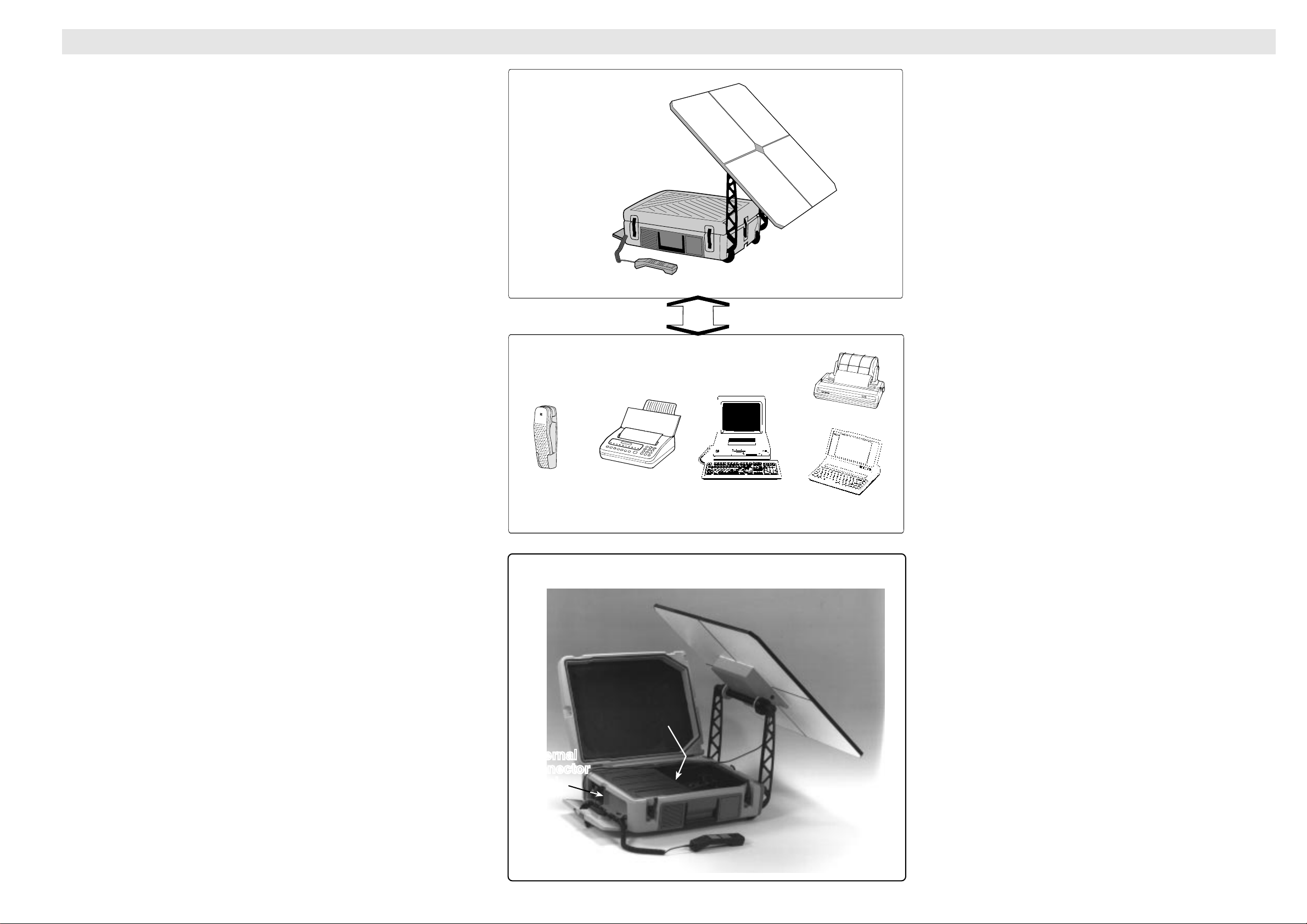
IntroductionIntroduction Saturn Bp Portable
External
connector
panel
External
connector
panel
Antenna sections
Transceiver
Supporting
legs
Display Handset
Internal
connector
panel
Introduction
Saturn Bp is a portable terminal for the Inmarsat-B system. It
provides a quickly established and very reliable link to terrestrial
networks.
The complete system including the four-section antenna, Main
Control Unit and RF equipment is packed in a compact and
robust case. Main connectors and telephone handset are easily
accessed from a compartment at one end. It is equipped with
wheels for easy transportation and total weight is only 18 kg.
Saturn Bp can be connected to a wide range of AC or DC supply
voltages and has an exceptional low power consumption. It
operates over a wide temperature range, withstands rain and
snow and is ideal for tough environments.
Features
• All equipment integrated in a lockable case.
• Low weight, small size.
• Antenna and RF electronics integrated may be remoted up
to 90 m dependent on type of coax cable.
Basic Equipment
Display Handset
Optional Equipment
• Wide range AC and DC operation.
• Additional outlets for telephone, fax and data.
• Last number redial and short number dialing via alphanumeric editing and recall facilities.
• Handset with built-in display and keypad for dialling, system
control and diagnostics, short number editing and signal
strength read-out.
• Design based on proprietary custom ASICs and Digital
Signal Processors giving stable trouble-free operation.
Optional equipment
• Standard DTMF telephones (max 5)
• Telefax (for connection to telephone inlet)
• PC for telex operation
• PC for High Speed Data transfer, 56/64 kbps or 9.6 kbps
modem communication
5 standard
telephones
Main Parts
Telefax
(replacing a
telephone) PC (Data)
Printer
PC (Telex)
• Printer
Saturn Bp Portable – Technical Manual
3
Page 6
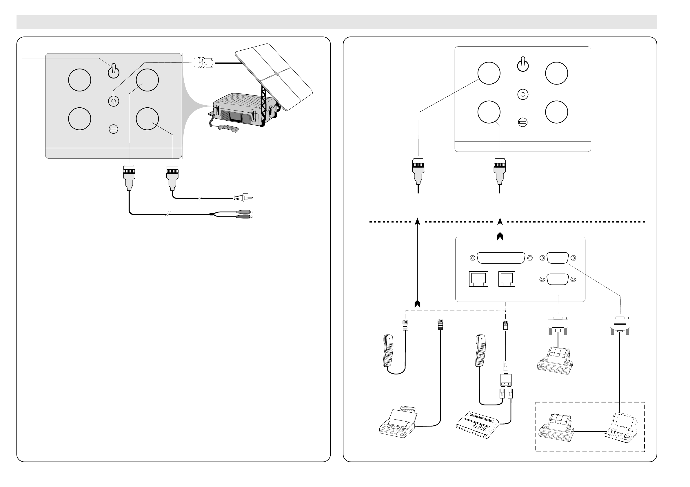
Connecting Up
External
connector
panel
Alternative external
connection to DTE
port.
Connection of additional
telephones/telefaxes
through special cable.
Internal
connector
panel
DTE
AUX
TEL.1
2W
PC
PRINTER
Telex
Centronics
Telephone
Telefax
with keypad
Telefax
without keypad
DATA
TLF.
UN ADAPTER 401
Telefax
adapter
TEL.
2-5
2W
DC
12V/24V
DTE
AC
100-250V
50-60 Hz
ON
OFF
ANTENNA
AC FUSE
6.3A SLOW
CONNECT AC TO EARTHED OUTLET ONLY!
Printer
w/RS232
Interface Card
RS232
External connector panel
Power
ON/OFF
ON
Connection of Optional Equipment
IntroductionIntroduction
Introduction
TEL.
2-5
2W
OFF
DC
12V/24V
AC
100-250V
50-60 Hz
ANTENNA
DTE
AC FUSE
6.3A SLOW
CONNECT AC TO EARTHED OUTLET ONLY!
Power consumption:
- receive: 28 W
- transmit: 110 W (total)
Caution! The DC supply must be connected with correct polarity.
Display
Handset
+ RED
- BLACK
90 - 276 VAC
(47 - 400 Hz)
w/ground
11 - 34 VDC
4
Saturn Bp Portable – Technical Manual
Page 7

IntroductionIntroduction
Introduction
Technical Data
General
Saturn Bp Portable complies with the INMARSAT-B System Definition Manual for a Land
Mobile Earth Station.
Operational Characteristics
• Assembly time < 60 seconds
• Antenna separation up to 90 meters
• 99 short numbers with alphanumeric names
• Last number redial
• Voice coding at 16 kbps
• Group III telefax at 9.6 kbps
• High Speed Data transfer at 64 kbps or 56 kbps
• Data modem transfer up to 9.6 kbps
Power Supply
AC power:
DC power:
Power consumption:
90 VAC - 276 VAC / 47-400 Hz
(operative when connected to both AC an DC supply)
11 - 34 VDC
Typically 28 W receive, 110 W transmit (total)
Interfaces
MCU – AU:
Display Handset:
External connector panel:
Internal connector panel:
Coaxial cable with TNC-connectors
7-pin circular (AMP) connector (female)
• coaxial antenna connector
• 3-pin circular (AMP) coded connector (male) for external DC supply
• 3-pin circular (AMP) coded connector (male) for AC power
• 10-pin circular (AMP) connector (female) for standard telephones or
telefax (TEL. 2-5)
• 14-pin circular (AMP) RS232 Data Terminal Equipment connector (female)
• 4-pin RJ11 connector for standard telephone (TEL.1)
• 25-pin RS232 Data Terminal Equipment connector (female)
• 9-pin PC connector (female)
• 9-pin printer connector (male)
Display Handset
LCD display: 2 x 12 characters
Weight: 0.35 kg
Dimensions in milimetres: W: 56, H: 214, D:47
Carrying Case
Material
Contents:
Weight :
Dimensions in millimetres:
Moulded polyethylene case
• Main Control Unit (MCU)
• Antenna and RF units (integrated)
• Display Handset
• Compass, and
• Cables
18 kg
W: 630, H: 210, D: 480
System Specifications
Transmit frequencies:
EIRP:
RF channel spacing:
Antenna:
Antenna size:
Polarization:
G/T:
Controls:
1626.5 MHz - 1646.5 MHz
33/25 dBW
20 kHz
Four-section plane
0.6 m
Right-hand circular (RHC)
- 4 dB/K
On/off switch
Environmental Conditions
Operating temperature:
Storage temperature:
Rain:
Shock:
-25°C to +55°C
-50°C to +80°C
100 mm/hour
90 cm drop
Electromagnetic Compatibility
Radiated:
Conducted:
2
EN55022
EC 801
Saturn Bp Portable – Technical Manual
5
Page 8
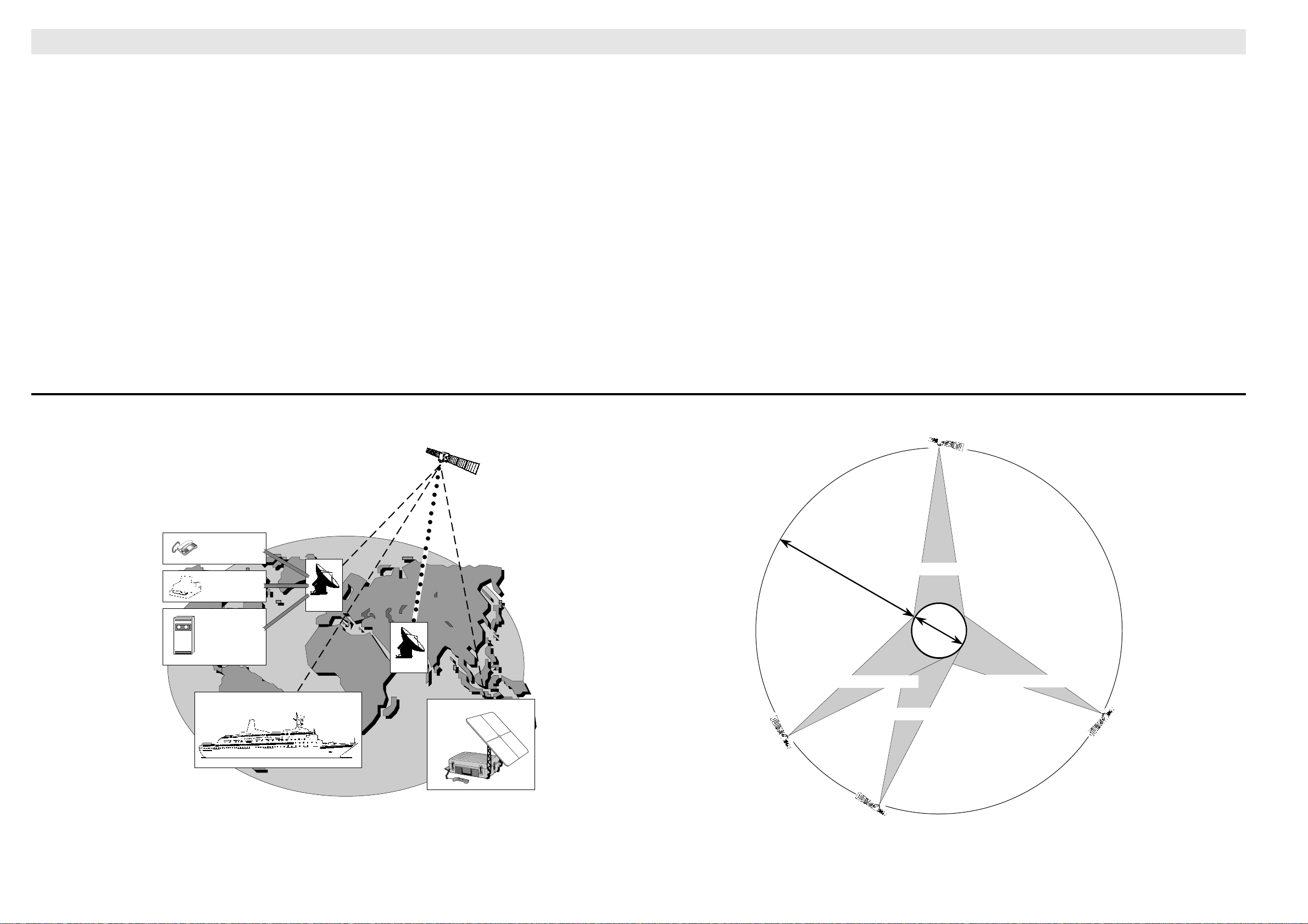
The INMARSAT-B System
System DescriptionSystem Description
System Description
Inmarsat
The INMARSAT-B system offers high quality 16 kbps
voice communication, and 9.6 kbps telefax and data
transmission.
The benefit of the INMARSAT system is its high
capacity, and the rapid and reliable connection
between the land based (fixed) users and the Mobile
Earth Stations (MESs).
The large number of Land Earth Stations (LESs) in
operation allows the operator to select the one giving
the lowest cost to a particular land based subscriber.
Each satellite region is under the control of a Net-
work Coordinating Station (NCS), which controls
and monitors the traffic between the MESs and the
LESs.
See figure 1.
Services
• Duplex telephone calls – basic telephony services
• Simplex telephone calls – LES-to-mobile only
• Duplex telefax – CCITT Group 3 facsimile services, 9.6 kbps
• Simplex telefax calls – LES-to-mobile only
• Simplex group ID addressing – to a selected
group of mobiles
• Simplex area addressing – to all mobiles within a
specific geographic area
• Duplex data communication – Hayes compatible
9.6 kbps data service
System Satellites
The satellites are positioned in a geostationary orbit
above the equator at approximately 35700 km altitude.
In geostationary orbit, each satellite moves at the
same rate as the earth, and so remains in the same
relative position to the earth, above equator, allowing
the antenna to have line-of-sight communication with
the satellite.
The Saturn Bp Portable can communicate via the
four satellites covering one Ocean Region each.
The positions of the system satellites are shown in
figure 2.
Transmission frequencies
The INMARSAT-B MESs operate in the following
frequency bands:
Calls from Saturn B terminals 1626.5 MHz — 1646.5 MHz
Calls to Saturn B terminals 1530.0 MHz — 1559.0 MHz
A large number of channels are available (20 kHz
channel separation), offering either 16 kbps voice
communication, or 9.6 kbps duplex data communication.
Duplex communication uses two channel frequencies, one in each direction.
The LESs provide interface to the international
networks for telephony and data: PSTN (Public
Switched Telephone Networks) and PSDN (Packet
Switched Data Networks).
NCS: Network Coordinating Station
LES: Land Earth Station
MES: Mobile Earth Station
(Saturn B terminal)
TELEPHONE
Re
P
7
–
4
8
1
5
9
✳
2
6
0
3
#
R
NETWORKS
TELEX
NETWORKS
LES
DATA
NETWORKS
MES
NCS
MES
35700 km
Pacific Ocean Region
Atlantic Ocean Region (West)
Atlantic Ocean Region (East)
55.5°W
179°E
Q
U
E
A
T
O
12000 km
EARTH
R
Indian Ocean Region
63°E
Figure 1.
Overview of the Inmarsat-B system.
6
18.5°W
Figure 2.
Four satellites in a geostationary orbit above the
equator at approx. 35700 km altitude.
Saturn Bp Portable – Technical Manual
Page 9
System DescriptionSystem Description
System Description
The INMARSAT-B System Cont’d
Channel numbers
All radio frequency channels used by the MES are
assigned a particular hexadecimal number which is
translated into frequencies on L-band between MES
and satellite, and to C-band between LES and satellite.
Channel no. 32C8 for an MES always designates:
1660.5000 MHz transmitting frequency
1542.5000 receiving frequency
Channel Types
The Inmarsat-B System differs between physical and
functional channels. A physical channel refers to one
frequency, one carrier. Every frequency can have
several functional channels muliplexed on it. Each
functional channel is named after the originating unit.
The NCS TDM will in the initial system multiplex the
NCSC for Bulletin Boards and Call Announcement,
the NCSA for Channel Assignments and NCSI for
Interstation information to the LES on the same
physical channel. When the system expands, spot
beams and Ocean Region Registration will be introduced using the functional channels NCSS and
NCRA multiplexed on the NCS TDM. The traffic on
one TDM may then be to heavy and some of the
functional channels may be moved to another NCS
TDM frequency.
The physical SCPC channels are always divided into
three functional channels. During call set up and
release the whole bandwith is used for signalling and
the functional channel is called MES-SIG/LES-SIG.
During speech or data phase, the signalling part of
the channel is called VSUB or DSUB and the service
carrying part is called MESV/LESV or MESD/LESD.
Requests and assignments
The Network Coordinating Station in each Ocean
Region continually transmits to the MESs within its
region on the NCS Common Signalling Channel
(NCSC).
When selecting a particular Ocean Region, the MES
automatically tunes its receiver to the NCSC frequency, and awaits System Information from the
NCS.
The System Information (Bulletin Board) includes
available NCS/LES channel frequencies, location of
satellites, operational status, etc.
When the NCS sends a Call Announcement, detailing the channel to which the MES should tune to
receive the call.
When the MES user dials a subscriber’s international
telephone number, the MES transmits an Access
Request to the NCS via the LES, and awaits a Channel Assignment from the NCS.
Telephone communication
For telephone communication a Frequency Division
Multiple Access (FDMA) is used, in a Single Channel
Per Carrier (SCPC) system. The voice communication occupies two (unpaired) channel frequencies.
The telephone channels are controlled by NCS which
assigns a free channel upon request. When a channel has been assigned it is controlled by LES until
end of call.
Facsimile communication
The Saturn Bp telephone ports may be configured for
telefax communication. The transmission is telefax
only, and is performed at a rate of 9.6 kbps.
Telefaxes without keypad may be connected via an
adapter.
Data communication
The data service allows the Saturn Bp user to communicate at up to 56/64 kbps, via the public switched
network, to fixed modems and data terminals.
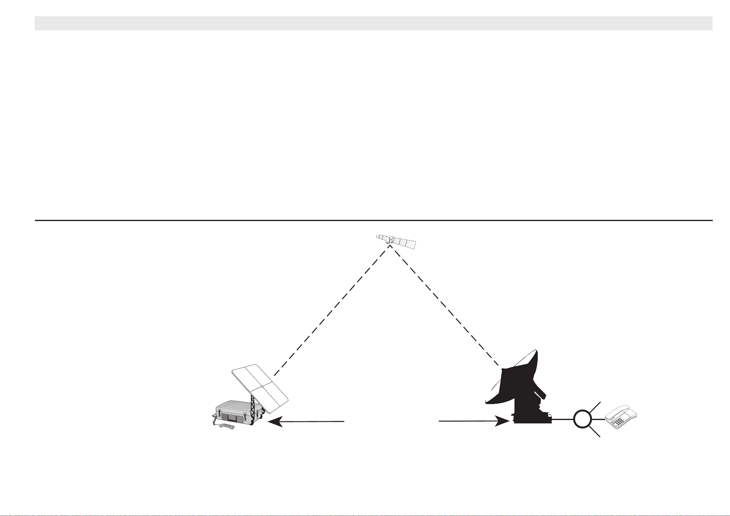
Figure 3.
Communication path.
Saturn Bp Portable – Technical Manual
Saturn Bp
Portable
Display handset
Standard telephones
Telefax
Data/modem communication (option)
Path established by
Saturn Bp terminal
via satellite.
Land Earth
Station
LES
Telefax
PC
w/modem
Public
Telephone
Network
Re
P
7
–
4
8
1
5
9
✳✳
2
6
0
3
#
R
7
Page 10
Calls from Mobiles
PSTN
6
1
2
3
4
5
#
7
8
9
*
0
DEL
FUNC
ALPHA
ENTER
MORE/
HELP
SHIFT
LES
ON/OFF
DIAL 00+INTL
TEL . NO . + f
00 47 66 84 47 00 f
Calls from Mobiles
Forward/return ID
123456/ABCDEF
OI1Type
Voice
Commissioned
Yes
66 84 47 00
LES
Return ID
Type
2
ABCDEF
Voice
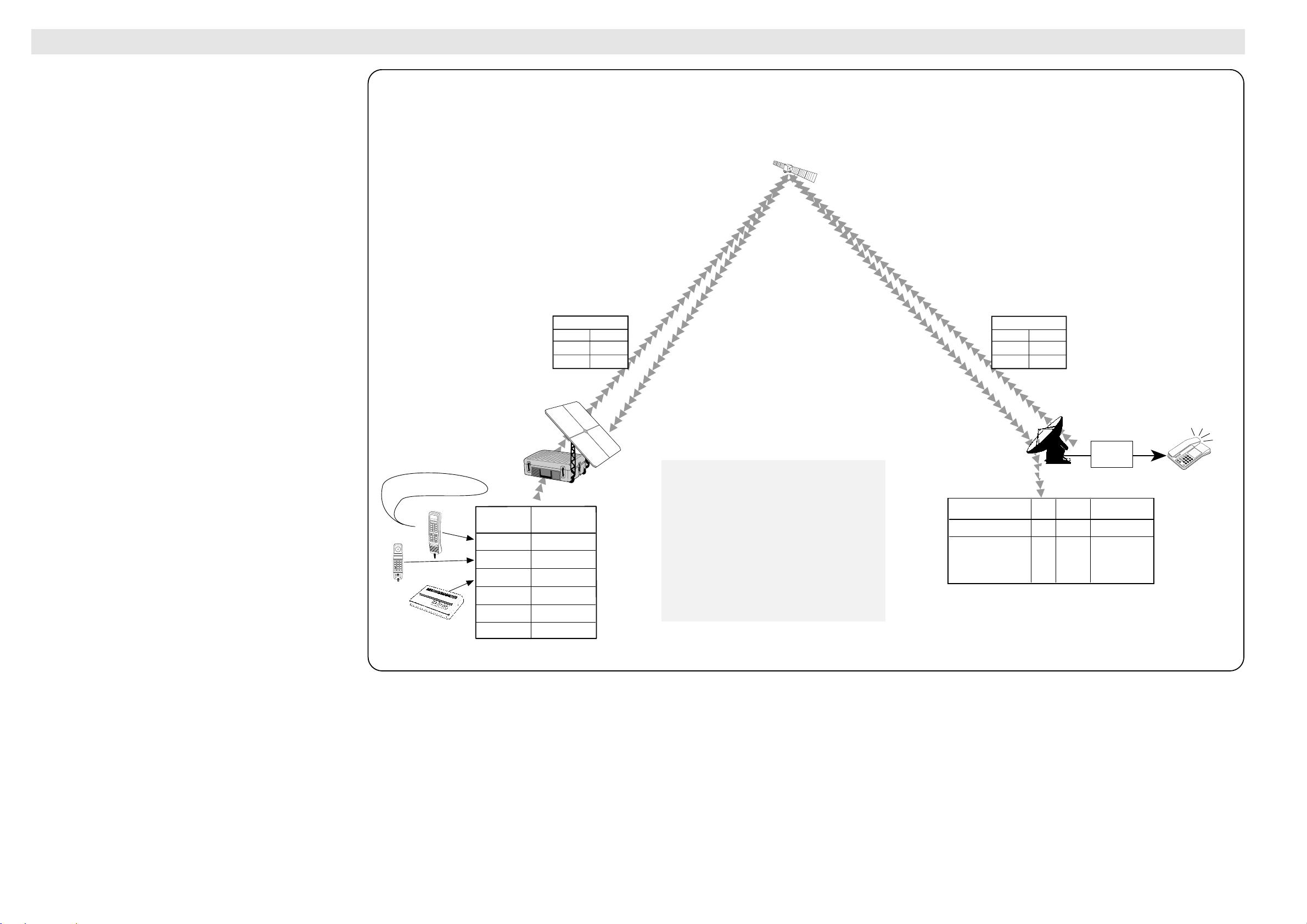
Access Request
When the MES originates a call it starts
by sending a request to the LES. This
initial request for service contains the
MES Return ID and type of service.
Saturn Bp incorporates a configuration
table for originating information,
accessible through the “Configure Ports”
function (70). This table contains one
entry for every physical connector with
the Originating Id and type of service for
that specific connector.
LES Translation Table
MES Translation Table
1 2 3
4 5 6
7 8 9
0 #
P S Re
Fwd ID
Rx ch.
Tx ch.
123456
8192
12000
Channel Assignment
Connector
Service/
Originating Id
Phone/OI=1
Phone/OI=2
Fax/OI=17
Default=no OI
Default=no OI
Default=no OI
HANDSET
TEL.1 (int.)
TEL.2 (ext.)
TEL.3 (ext.)
TEL.4 (ext.)
TEL.5 (ext.)
LES=2
☞
Re
P
–
7
8
9
4
5
6
1
2
3
✳
0
#
R
To initiate a call, the user dials the international call prefix 00
prior to the telephone number for the required destination.
The LES code is also included, either automatically when
using the default LES, or manually selected from the Display
Handset.
The mobile automatically includes information to identify the
MES and the particular end terminal that originates the call.
Saturn Bp Portable has six voice connections: the Display
Handset and five connectors (one internal and four external)
that are normally configured for standard telephone and a
telefax.
The LES uses the end terminal identifying information (OI)
for billing purposes.
The mobile transmits the dialling information on a channel
specially assigned by the NCS, to the LES, which also has
been instructed to tune to the same channel.
On receiving the call, LES routes it over the public telecommunications networks to the intended destination. When the
destination responds, for example by the dialled subscriber
lifting the handset, the call proceeds.
System DescriptionSystem DescriptionSaturn Bp Portable Communication
System Description
The illustration of the call initiation is simplified.
8
Saturn Bp Portable – Technical Manual
Page 11
System DescriptionSystem Description
Re
P
–
7
8
9
4
5
6
1
2
3
✳
0
#
R
6
1
2
3
4
5
#
7
8
9
*
0
DEL
FUNC
ALPHA
ENTER
MORE/
HELP
SHIFT
LES
ON/OFF
DIAL 00+INTL
TEL . NO . + f
Calls to Mobiles
00 871 681234567
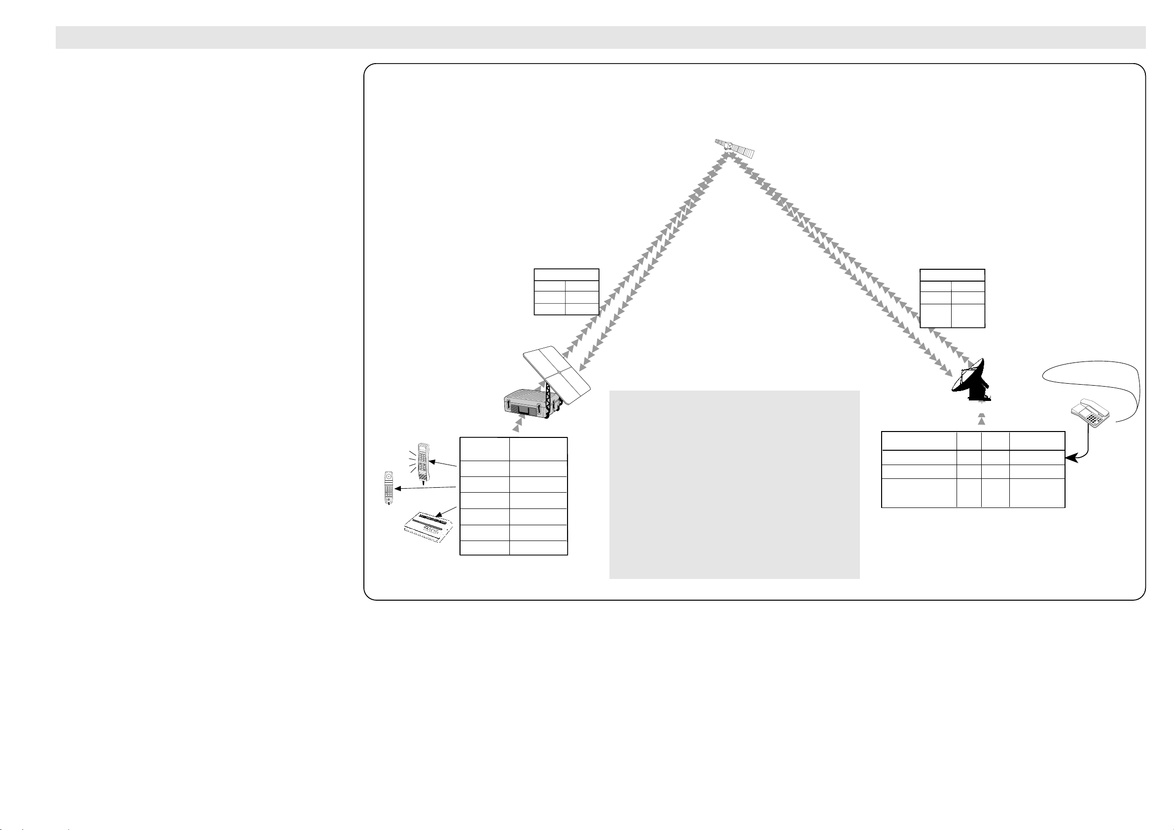
When requested to call a specific IMN, LES translates
the IMN to a Forward ID and a Destination Id (DI). The
request is then sent to the MES which translates the
Forward ID and the DI to a physical line to call.
To "connect" a Destination Id to a physical line,
SaturnBp incorporates a translation table accessible
through the “Incoming call route” function (71).
This table can contain up to 100 DI translations, and
each DI in use is programmed with type of call and
destination.
A call is not allowed to be routed to a connector that is
configured to another type than the DI specifies.
A telephone DI can only be routed to a phone type
connector type. A facsimile DI can only be routed to a
fax type connector.
Forward/return ID
123456/ABCDEF
123456/ABCDEF
123456/ABCDEF
DI
01
02
17
Type
Voice
Voice
Fax
IMN
681234567
681234789
681234890
LES Translation Table
MES Translation Table
☞
1 2 3
4 5 6
7 8 9
0 #
P S Re
Connector
Service/
Originating Id
Phone/OI=1
Phone/OI=2
Fax/OI=17
Default=no OI
Default=no OI
Default=no OI
HANDSET
TEL.1 (int.)
TEL.2 (ext.)
TEL.3 (ext.)
TEL.4 (ext.)
TEL.5 (ext.)
LES
Return ID
Type
2
ABCDEF
Voice
Response
LES
Fwd ID
Type
DI
2
123456
Voice
1
Call announcement
LES=2
System Description
Calls to Mobiles
Calls are made as ordinary international (Satellite) calls
where each Ocean Region has an international country
code. If an area is covered by more than one satellite, it is
necessary that the caller knows which satellite (Ocean
Region) the mobile is tuned to.
The international codes to the four Ocean Regions are as
follows:
Atlantic Ocean East Region: 871
Pacific Ocean Region: 872
Indian Ocean Region: 873
Atlantic Ocean West Region: 874
The illustration of the call initiation is simplified.
Saturn Bp Portable Communication Cont’d
Saturn Bp Portable – Technical Manual
9
Page 12

System DescriptionSystem Description
System Description
10
Saturn Bp Portable – Technical Manual
Page 13
NCS Common Ch (NCSC)
NCS Assignment Ch (NCSA)
NCS Registration (NCRA)
NCS Spot beam (NCSS)
MES
Saturn Bp
Portable
terminal.
MES Request Ch (MESRQ)
MES Region Registration Ch (MESRR)
MES Call Acknowledge Ch (MESCA)
SCPC In-band Signalling (MESSIG)
SCPC In-band Signalling (LESSIG)
SCPC Voice (MESV/VSUB)
SCPC Voice (LESV/VSUB)
SCPC Data (MESD/DSUB)
SCPC Data (LESD/DSUB)
LES
The Land Earth Station
routes messages to/from
the MESs within the
coverage area of one of
the four Inmarsat
satellites.
NCS/NCS
Signalling Links
NCS
The Network Coordinating
Station controls the satellite
resources to LESs and
MESs within a single
satellite coverage area.
MES Region Registration Ch (MESRR)
MES Response Ch (MESRP)
MES Request Ch (MESRQ)
NCS Interstation Ch (NCSI)
LES Interstation Ch (LESI)
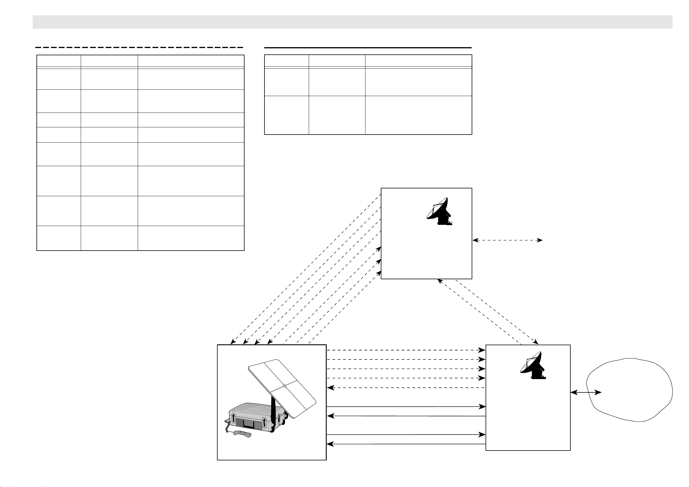
Signalling Channels
Communication Channels
(SCPC = Single Channel Per Carrier)
Public Switched
Telephone
Networks
ISDN
Packet Switched
Data Networks
System DescriptionSystem Description
System Description
Signalling & Communication Channels
Signalling Channels
Designation Transmission Type of information
NCSI
LESI
NCSC
MESRP
NCSA
MESRQ
MESCA
NCSS
MESRR
NCRA
MESSIG
LESSIG
Continuous TDM
TDM Bulletin Board announcements.
TDMA MES responses
Continuous TDM Assigns SPCS channels
Slotted Aloha Request from MES to LES
Slotted Aloha Acknowledges shore-originated
Continuous TDM One frequency per spot beam;
Slotted Aloha Registration signal to LES/NCS.
Continuous TDM Acknowledgement from NCS to
SCPC In-band signalling
Bi-directional signalling information
between LES and NCS
simplex calls.
enables an MES to identify beam
serving location.
MES
Communication Channels
Designation Transmission Type of information
LESV
MESV
LESD
MESD
SCPC with Duplex 16 kbps voice
VSUB sub-band communication
signalling
SCPC with Duplex 9.6 kbps data
VSUB sub-band communication
signalling
Saturn Bp Portable – Technical Manual
11
Page 14
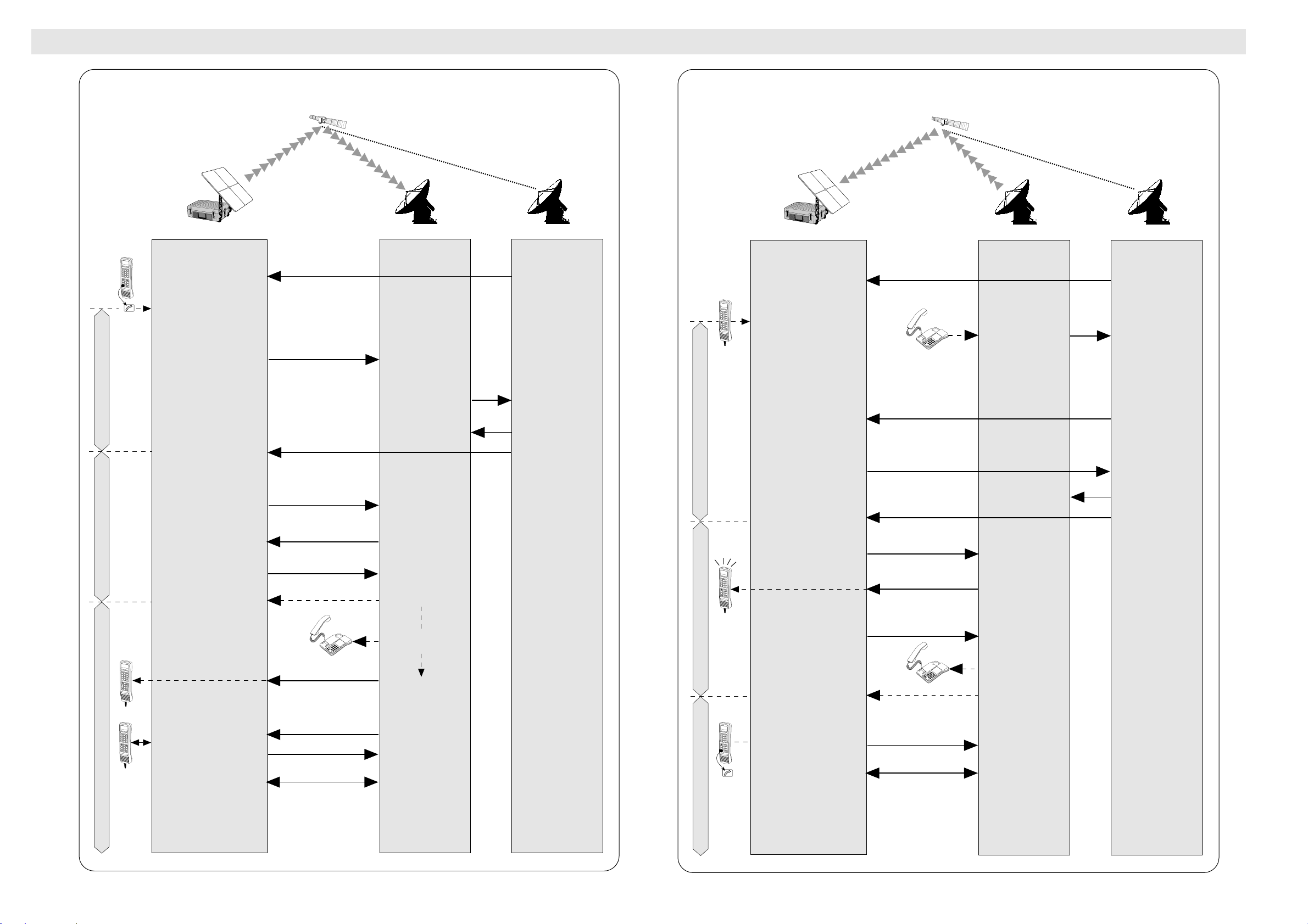
Set-up
SCPC In-band Signalling
SCPC Voice Mode
Listens to NCS common
channel.
NCS Common Channel
MES number from
telephone network.
Validates MES
authorization.
Adds MES to LES
busy list. "Request
for Call
Announcement" SU.
NCSI
NCSA
LESI
NCSC
Transmits "Channel
Assignment" SU.
NSCA: Once for
maritime MES. Three
times for Land
mobile MES.
MESRP
Transmits "MES
Response" SU on the
TDMA channel.
Adds MES to NCS
busy list.
"Call Announcement"
SU. Repeated once if
no response from
Land Mobile MES.
MES
Mobile Earth Station
LES
Land Earth Station
NCS
Network
Coordination
Station
For call release, see
separate diagram
Sets SCPC channel in "Inband Signalling" mode.
Transmits "Scrambling
Vector Advice" SU
repeatedly.
MES-SIG
Returns
"Scrambling Vector
Acknowledge" SUs
repeatedly.
LES-SIG
RINGING
Ringing tone
(generated by LES)
MES-SIG
Transmits "Return Carrier
Identifier" SUs.
Switches to MESV/SUB
mode
OFF-HOOK
Transmits "Connect" SUs
"Fill-in" SUs when
quiet.
Maintains burst SU
every 5 secs to
prevent clearing by
LES.
Transmits speech
and "MES Connect"
SUs continuously.
SUB
SUB
INMARSAT-B
Fixed-originated Duplex Telephone Call
6
1
2
3
4
5
#
7
8
9
*
0
DEL
FUNC
ALPHA
ENTER
MORE/
HELP
SHIFT
LES
ON/OFF
DIAL 00+INTL
TEL . NO . + f
6
1
2
3
4
5
#
7
8
9
*
0
DEL
FUNC
ALPHA
ENTER
MORE/
HELP
SHIFT
LES
ON/OFF
DIAL 00+INTL
TEL . NO . + f
6
1
2
3
4
5
#
7
8
9
*
0
DEL
FUNC
ALPHA
ENTER
MORE/
HELP
SHIFT
LES
ON/OFF
DIAL 00+INTL
TEL . NO . + f
ESC
☞
Re
P
–
7
8
9
4
5
6
1
2
3
✳
0
#
R
Re
P
–
7
8
9
4
5
6
1
2
3
✳
0
#
R
INMARSAT-B
MES-originated Duplex Telephone Call
System DescriptionSystem DescriptionCommunication Sequences
System Description
DIAL 00+INTL
TEL . NO . + f
1
2
3
4
5
Listens to NCS common
6
7
8
9
0
*
#
DEL
FUNC
ALPHA
ENTER
MORE/
channel.
HELP
SHIFT
LES
ON/OFF
ESC
☞
OFF-HOOK
MES operator dials
subscriber’s international
telephone number.
Transmits "Access Request"
SU.
Set-up
Sets SCPC channel in "Inband Signalling" mode.
Transmits "Service Address"
SUs and "Scrambling Vector
Advice" SU alternately.
SCPC In-band Signalling Mode
SCPC Voice Mode
"Return Carrier Identifier"
SUs
Changes to MESV/SUB
mode
DIAL 00+INTL
TEL . NO . + f
1
2
3
4
5
6
7
8
9
"Ringing tones"
0
*
#
DEL
FUNC
ALPHA
ENTER
MORE/
HELP
SHIFT
LES
ON/OFF
DIAL 00+INTL
TEL . NO . + f
1
2
3
4
5
6
7
8
9
0
*
#
ENTER
LES
Transmits "MES
Connect" SUs.
DEL
FUNC
ALPHA
MORE/
HELP
SHIFT
ON/OFF
Transmits speech
and "MES Connect"
SUs continuously.
12
MES
Mobile Earth Station
NCS Common Channel
LES Voice Channel
For call release, see
separate diagram
MESRQ
MES-SIG
LES-SIG
MES-SIG
Re
P
7
–
4
8
1
5
9
✳
2
6
0
3
#
R
LESV & SUB
and sub-band
signalling
SUB
SUB
SUB
LES
Land Earth Station
Adds MES to LES
busy list.
"Request for Channel
Assignment" SU
Returns "Scrambling
Vector Acknowledge"
SU.
Changes to
LESV/SUB mode.
Terrestrial call set-up
procedure.
Transmits "Ringing
Tone" & "Fill-in" SUs.
Sends answer signal
& "LES Connect" SUss
"Fill-in" SUs when
quiet.
Maintains burst SU
every 5 secs to
prevent clearing by
MES.
LESI
NCSI
NCSA
NCS
Network
Coordination
Station
Adds MES to NCS
busy list.
Transmits "Channel
Assignment" SU.
NCSA:
Once for maritime
MES. Three times for
Land mobile MES.
Saturn Bp Portable – Technical Manual
Page 15
System DescriptionSystem Description Communication Sequences Cont’d
System Description
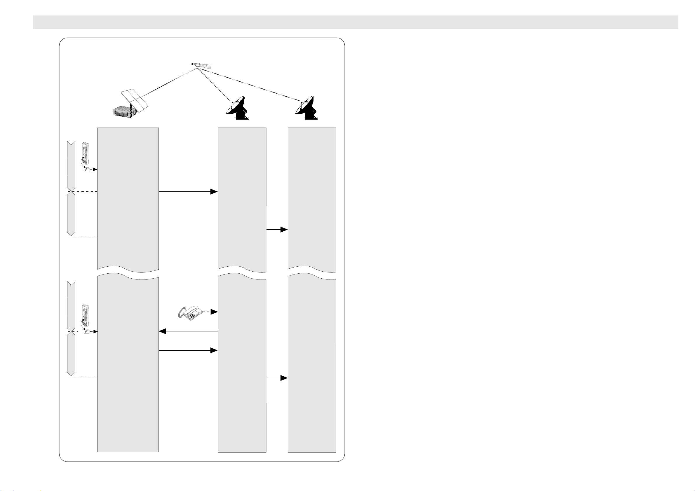
INMARSAT-B
MES or Fixed Call Release
Mobile Earth Station
DIAL 00+INTL
TEL . NO . + f
1
2
3
4
5
6
7
8
9
0
*
#
DEL
FUNC
ALPHA
ENTER
MORE/
HELP
SHIFT
LES
ON/OFF
ESC
☞
ON-HOOK.
MES switches to "In-band
Voice Mode
signalling" mode and sends
6 frames of "Channel
Release" SUs,
then turns off carrier.
Signalling Mode
MES
MES-SIG
LES
Land Earth Station
Clear forward.
Observes MES
carrier off, then turns
off LES carrier and
sends "Notification of
Channel Release"
SU to NCS.
Removes MES from
LES busy list.
LESI
NCS
Network
Coordination
Station
Removes MES from
NCS busy list, and
updates channel
status table.
DIAL 00+INTL
TEL . NO . + f
1
2
3
4
5
6
7
8
9
0
*
#
DEL
FUNC
ALPHA
ENTER
MORE/
HELP
SHIFT
LES
ON/OFF
Voice Mode
ESC
☞
ON-HOOK.
MES switches to "In-band
signalling" mode and
sends 6 frames of
channel release SUs,
then turns carrier off.
Signalling Mode
Terrestrial side
ON-HOOK
Re
P
7
–
4
8
1
5
9
✳
2
6
0
3
#
R
LES-SIG
MES-SIG
Switches to "In-band
signalling" mode and
sends channel
release SUs.
(Delay up to 2 min if
called party)
Observes MES
carrier off, then turns
off LES carrier and
sends "Notification of
Channel Release"
SU to NCS.
Removes MES from
LES busy list.
LESI
Removes MES from
NCS busy list, and
updates channel
status table.
Saturn Bp Portable – Technical Manual
13
Page 16
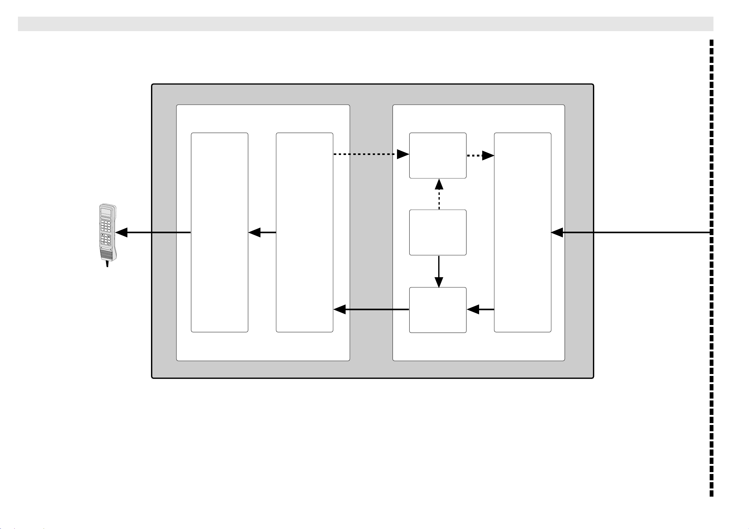
Idle State
MAIN CONTROL BOARD
System DescriptionSystem Description
System Description
BDE
DIAL 00+INTL
TEL . NO . + f
1
4
7
*
FUNC
MORE/
HELP
Digital Signal Processor Sub-system
TXIF
Transmitter
2.5 MHz
2
3
5
6
8
9
0
#
DEL
ALPHA
ENTER
SHIFT
LES
ON/OFF
Telephony
Interface
Computer
Codec
Local
Oscillator
Synthesizer
RF Sub-system
TX Channel
1626.5 -
1660.5 MHz
Combiner/
splitter
RXIF
12 MHz
Receiver
RX Channel
1525 1559 MHz
14
Saturn Bp Portable – Technical Manual
Page 17
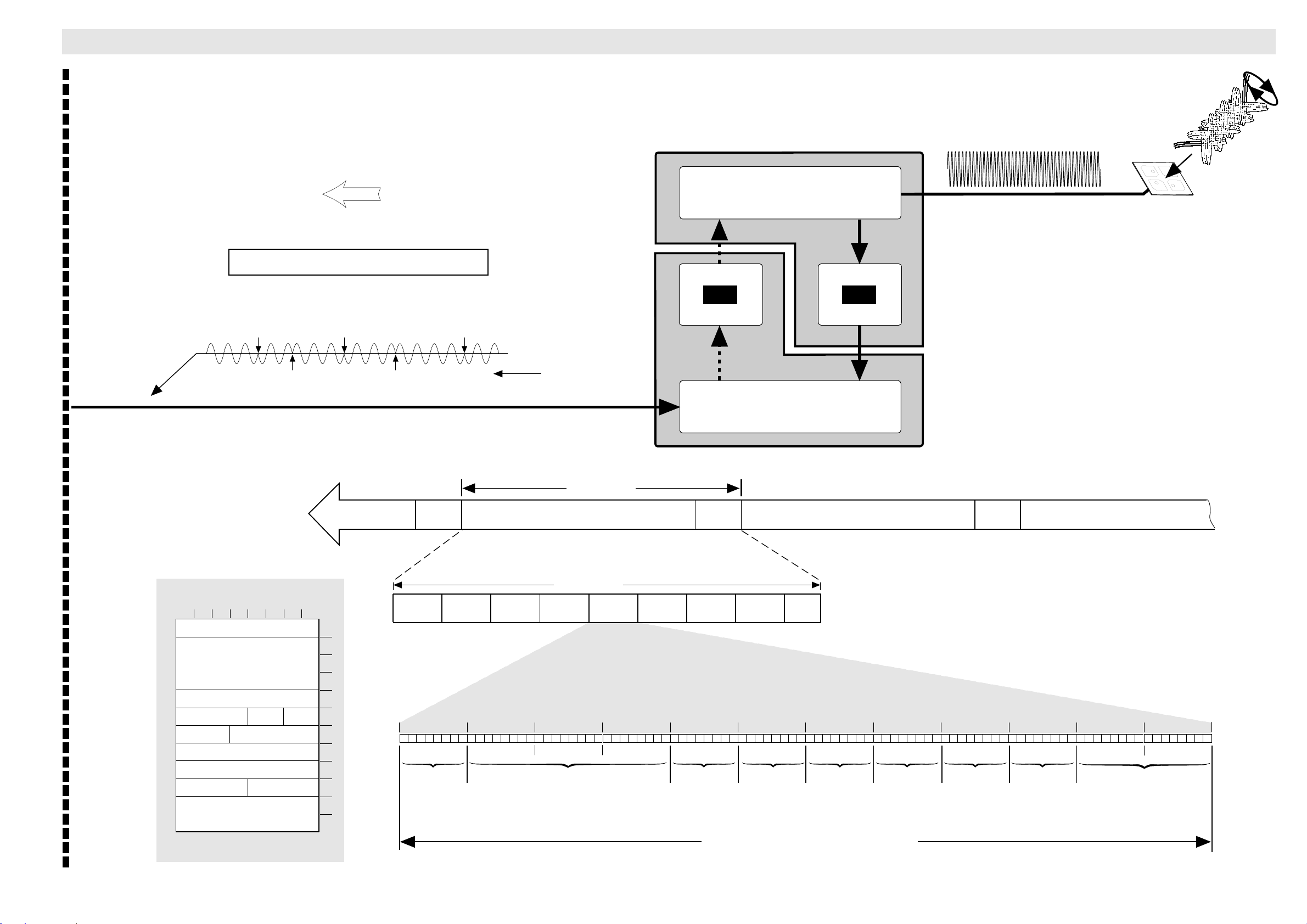
System DescriptionSystem Description Idle State
System Description
ADE
Right Hand Circular
polarized RF signal
Forward Direction
RF Units
f = 1525 - 1559 MHz
MES NCS
NCS Common Channel (NCSC)
BPSK Encoded Signal
(BPSK = Binary Phase Shift Keying)
shift
shift shift
shiftshift
FRAMING
BITS
32
t
Approx. 264 ms
RATE - 1/2 FEC CODED BITSTREAM
1552 bits
HPA
FRAMING
BITS
32
Duplexer
Combiner/splitter
RATE - 1/2 FEC CODED BITSTREAM
LNA
1552 bits
FRAMING
BITS
32
RATE - 1/2 FEC CODED BITSTREAM
1552 bits
SIGNALLING UNIT – SU
BIT No.
8 7 6 5 4 3 2 1
Message type
MES ID
LES ID
priorityspare spare
service nature service type
channel parameters
destination terminal ID
spare message number
CCITT CRC
M1
CALL ANNOUNCEMENT
Saturn Bp Portable – Technical Manual
Approx. 264 ms
7
00
MULTI
FRAME
8 bits96 bits
H
SPARE
PRIORITY
01
NATURE
SERVICE
H
TYPE
SRVICE
01
H
CHANNEL
PARAMETERS
01
H
DESTINATION
TERMINAL ID
00
SPARE
H
NUMBER
MESSAGE
54
H
(CYCLIC REDUNDENCY CHECK)
CCITT CRC
26
H
3
DD
TIMESLOT
96 bits
H
TIMESLOT
TIMESLOT
0
81
1
2
3
4
5
6
7
8
9
10
11
12
OCTET No.
96 bits
Octet No. 1 Octet No. 2 Octet No. 3 Octet No. 4 Octet No. 5 Octet No. 6 Octet No. 7 Octet No. 8 Octet No. 9 Octet No. 10 Octet No. 11 Octet No. 12
100000011110110011011101000110000000100100000000000000010000000100000001000000000101010000100110
MESSAGE
81
TYPE
96 bits
H
TIMESLOT
1
96 bits
EC
TIMESLOT
2
96 bits
H
MES ID
4
TIMESLOT
96 bits
18
H
TIMESLOT
5
96 bits
09
LES ID
TIMESLOT
6
H
SPARE
SIGNALLING UNIT = 12 "OCTETS" = 96 BITS
EXAMPLE: CALL ANNOUNCEMENT (TYPE 81
)
H
15
Page 18
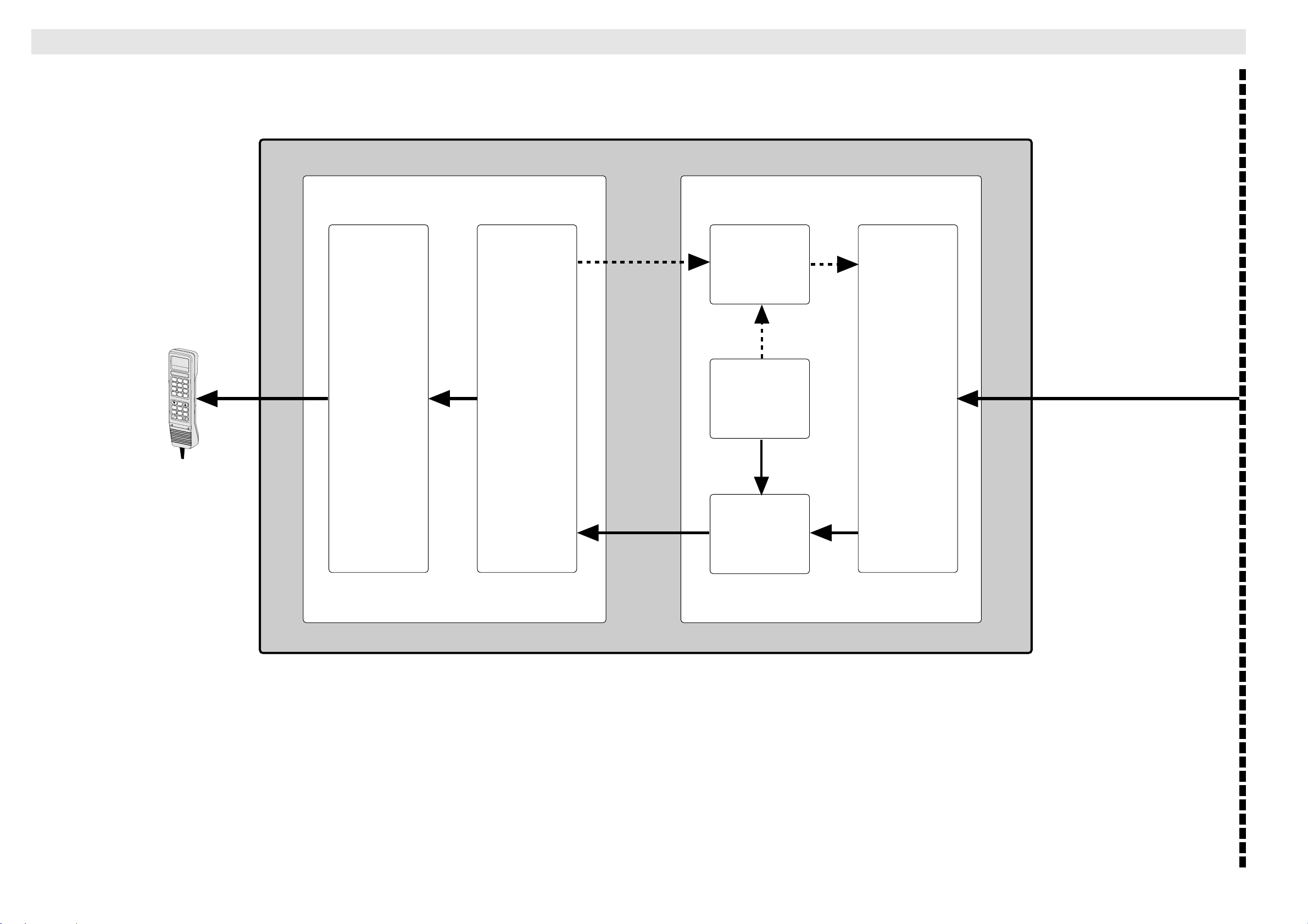
SCPC Signalling
MAIN CONTROL BOARD
System DescriptionSystem Description
System Description
BDE
DIAL 00+INTL
TEL . NO . + f
1
4
7
*
FUNC
MORE/
HELP
Digital Signal Processor Sub-system
TXIF
Transmitter
2.5 MHz
2
3
5
6
8
9
0
#
DEL
ALPHA
ENTER
SHIFT
LES
ON/OFF
Telephony
Interface
Computer
Codec
Local
Oscillator
Synthesizer
RF Sub-system
TX Channel
1626.5 -
1660.5 MHz
Combiner/
splitter
RXIF
12 MHz
Receiver
RX Channel
1525 1559 MHz
16
Saturn Bp Portable – Technical Manual
Page 19
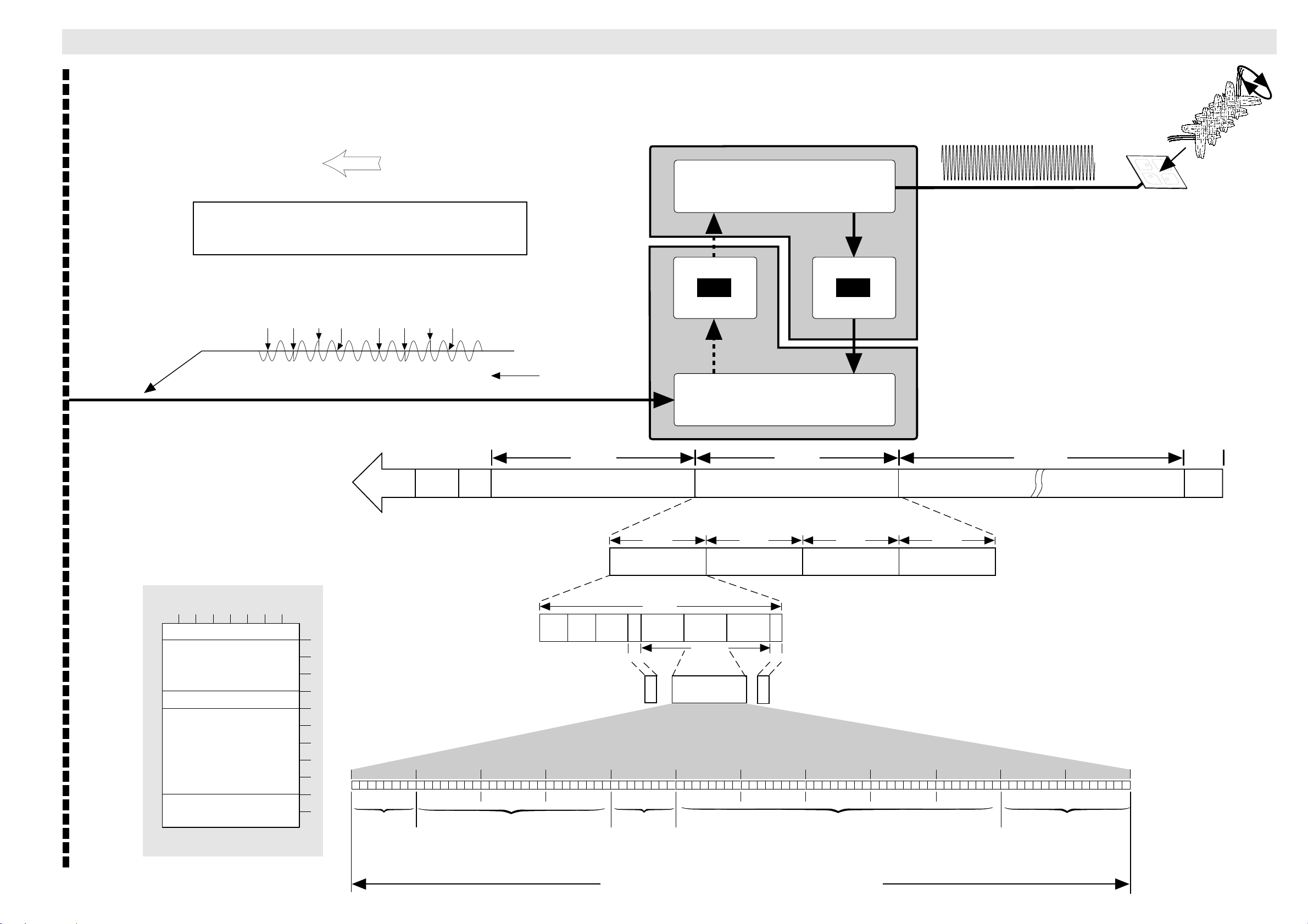
System DescriptionSystem Description SCPC Signalling
System Description
ADE
Right Hand Circular
Forward Direction
MES LES
SCPC Channel (Single Carrier Per Channel)
In-band Signalling Mode
RF Units
f = 1525 - 1559 MHz
Duplexer
polarized RF signal
O-QPSK Encoded Signal
(O-QPSK = Offset Quadrature Phase Shift Keying)
SIGNALLING UNIT – SU
8 7 6 5 4 3 2 1
SCRAMBLING VECTOR ACKNOWLEDGE
BIT No.
Message type
MES ID
LES ID
spare
CCITT CRC
M21
95
HPA
0°+90°+270°+180° 0°+90°+270°+180°
t
LNA
Combiner/splitter
240 ms240 ms 24 ms
CONTIN.
WAVE
96 bits
1
2
3
4
5
6
7
OCTET No.
8
9
10
11
12
Octet No. 1 Octet No. 2 Octet No. 3 Octet No. 4 Octet No. 5 Octet No. 6 Octet No. 7 Octet No. 8 Octet No. 9 Octet No. 10 Octet No. 11 Octet No. 12
100101011110110011011101000110000000100111110001101111000000011001111001110101010100101000001001
95
H
TYPE
BIT
TIMING
64 bits
* Unique Word:
0111 1000 1001
for 1st subframe, and
1000 0111 0110
for 2nd, 3rd and 4th
subframe (compliment)
EC
H
DD
H
MES IDMESSAGE
IN-BAND SIGNALLING FRAME
CW
24 bits
1920 bits
* UW
24 bits
Before FEC
coding
18
H
SUB
32 bits
60 ms 60 ms 60 ms 60 ms
SU
SUBFRAME - 1
60 ms
FLUSH
8
bits
DUMMY
6 bits
09
H
LES ID
IN-BAND SIGNALLING FRAME
SU
SUBFRAME - 2
SU1SU1
384 bits
96 BIT
SIGNALLING UNIT
F1
SU1
H
6 bits
BC
1920 bits
FLUSH
8
bits
DUMMY
H
(Random binary bits)
SU
SUBFRAME - 3
06
H
SPARE
SUBFRAME - 4
79
H
SU
D5
H
n x 240 ms
4A
H
(CYCLIC REDUNDENCY CHECK)
CCITT CRC
09
H
LES_SIG
SIGNALLING
CHANNEL
END OF
DATA
192 bits
Saturn Bp Portable – Technical Manual
SIGNAL UNITS = 12 "OCTETS" = 96 BIT SIGNALLING UNIT.
EXAMPLE: SCRAMBLING VECTOR ACKNOWLEDGE
17
Page 20
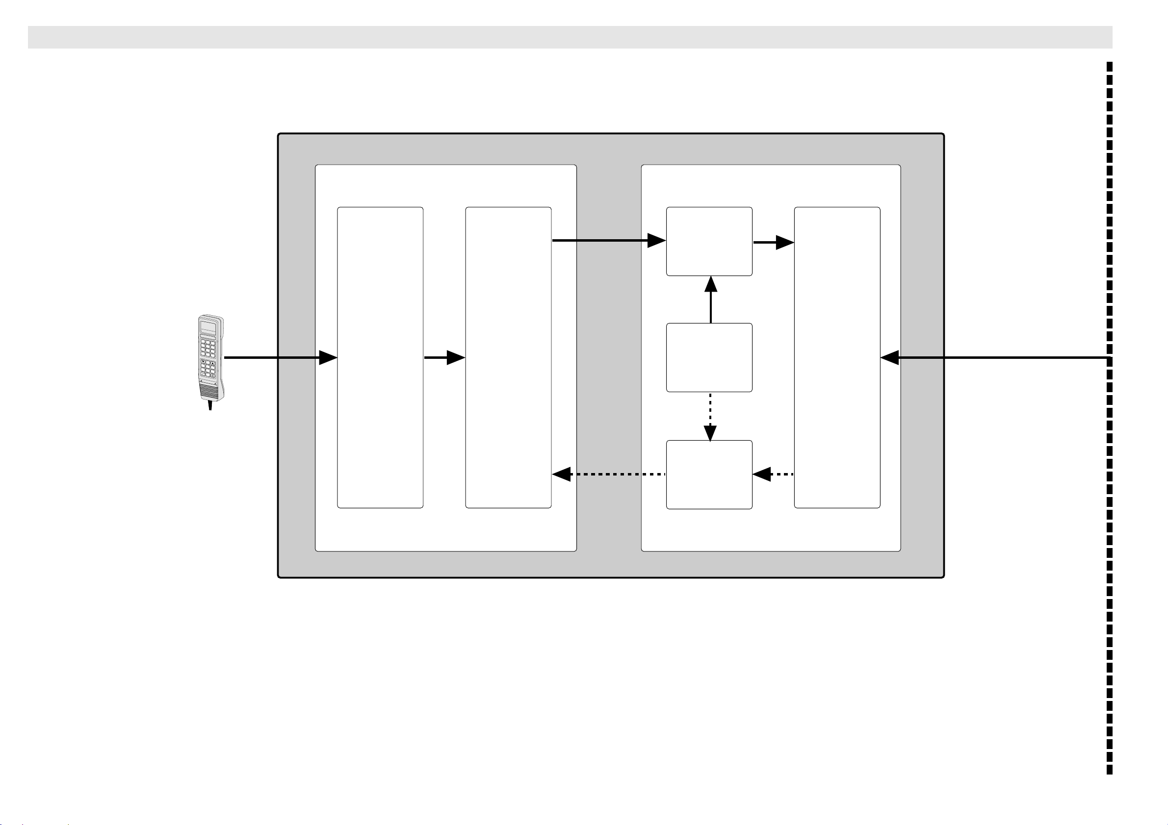
Voice
MAIN CONTROL BOARD
System DescriptionSystem Description
System Description
BDE
DIAL 00+INTL
TEL . NO . + f
FUNC
MORE/
HELP
Digital Signal Processor Sub-system
TXIF
Transmitter
2.5 MHz
1
2
3
4
5
6
7
8
9
0
*
#
DEL
ALPHA
ENTER
SHIFT
LES
ON/OFF
Telephony
Interface
Computer
Codec
Local
Oscillator
Synthesizer
RF Sub-system
TX Channel
1626.5 -
1660.5 MHz
Combiner/
splitter
RXIF
12 MHz
Receiver
RX Channel
1525 1559 MHz
18
Saturn Bp Portable – Technical Manual
Page 21
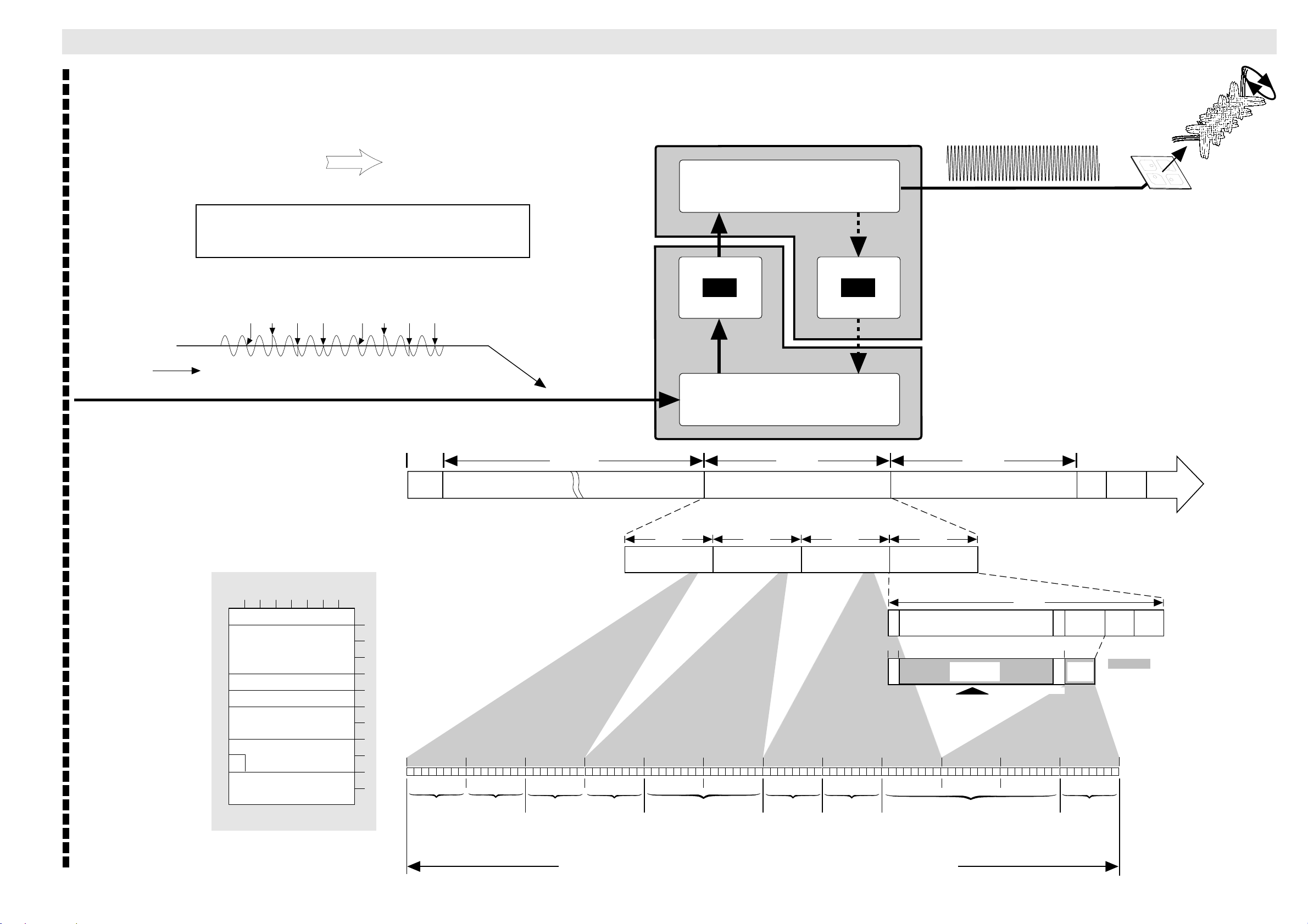
System DescriptionSystem Description Voice
System Description
ADE
Right Hand Circular
Return Direction
MES LES
SCPC channel (Single Carrier Per Channel)
Sub-band
RF Units
f = 1626.5 - 1660.5 MHz
Duplexer
polarized RF signal
OQPSK Encoded Signal
(OQPSK = Offset Quadrature Phase Shift Keying)
0° +90° +270° +180°
0° +90° +270° +180°
HPA
t
LNA
Combiner/splitter
n x 240 ms 240 ms 240 ms24 ms
SIGNALLING UNIT – SU
8 7 6 5 4 3 2 1
MSB
spare
BIT No.
Message type
MES ID
LES ID
spare
MES receive
channel number
scrambling vector
CCITT CRC
M25
MES CONNECT
LSB
8A
END OF
DATA
192 bits
60 ms 60 ms 60 ms 60 ms
VOICE
SUBFRAME - 4
1
2
3
4
5
6
7
OCTET No.
8
9
10
11
12
Octet No. 12 Octet No. 11 Octet No. 10 Octet No. 9 Octet No. 8 Octet No. 7 Octet No. 6 Octet No. 5 Octet No. 4 Octet No. 3 Octet No. 2 Octet No. 1
101001111000010101001110011101110001110001001100000000000000100110001010110110001001111110011001
A7
H
(CYCLIC REDUNDENCY CHECK)
CCITT CRC
85
H
4E
H
SCRAMBLING VECTOR
SPARE
77
H
21
H
CHANNEL NUMBER
SUBFRAME - 3
4C
VOICE FRAME
VOICE
H
1920 bits
00
H
SPAREMES RECEIVE
VOICE
SUBFRAME - 2
8 bits
8 bits
09
H
LES ID MES ID MESSAGE
VOICE
SUBFRAME - 1
DUMMY
DUMMY
8A
H
VOICE FRAME
1920 bits
VOICE FIELD
384 bits
VOICE FIELD
384 bits
Digital input from
voice encoder
D8
H
60 ms
9F
8 bits
6 bits
H
TIMING
SUB
32 bits
FLUSH
SUB
24 bits
DUMMY
BIT
CONTIN.
64 bits
TYPE
WAVE
96 bits
* Unique Word:
0111 1000 1001
for 1st voice frame, and
1000 0111 0110
for 2nd, 3rd and 4th
subframe (compliment)
* UW
24 bits
24 bits
Scrambled
MES_SIG
SIGNALLING
99
CHANNEL
H
CW
Saturn Bp Portable – Technical Manual
SIGNALLING UNITS = 12 "OCTETS" = 96 BITS = 24 BITS FROM EACH OF THE 4 VOICE FRAMES
EXAMPLE: MES CONNECT
19
Page 22
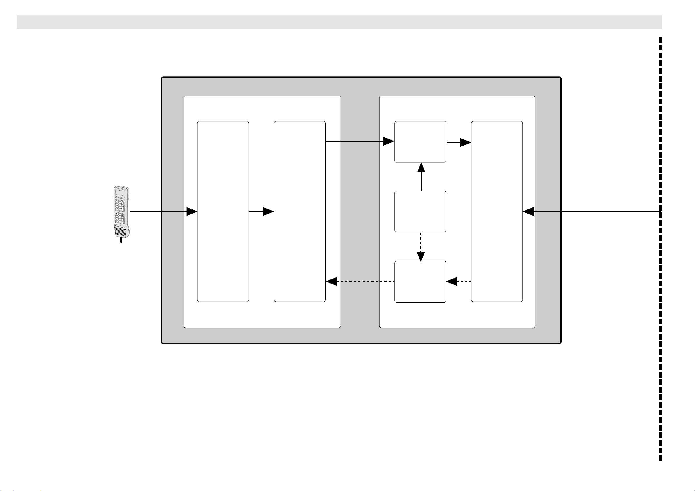
Clearing
MAIN CONTROL BOARD
System DescriptionSystem Description
System Description
BDE
DIAL 00+INTL
TEL . NO . + f
1
4
7
*
FUNC
MORE/
HELP
Digital Signal Processor Sub-system
TXIF
Transmitter
2.5 MHz
2
3
5
6
8
9
0
#
DEL
ALPHA
ENTER
SHIFT
LES
ON/OFF
Telephony
Interface
Computer
Codec
Local
Oscillator
Synthesizer
RF Sub-system
TX Channel
1626.5 -
1660.5 MHz
Combiner/
splitter
RXIF
12 MHz
Receiver
RX Channel
1525 1559 MHz
20
Saturn Bp Portable – Technical Manual
Page 23
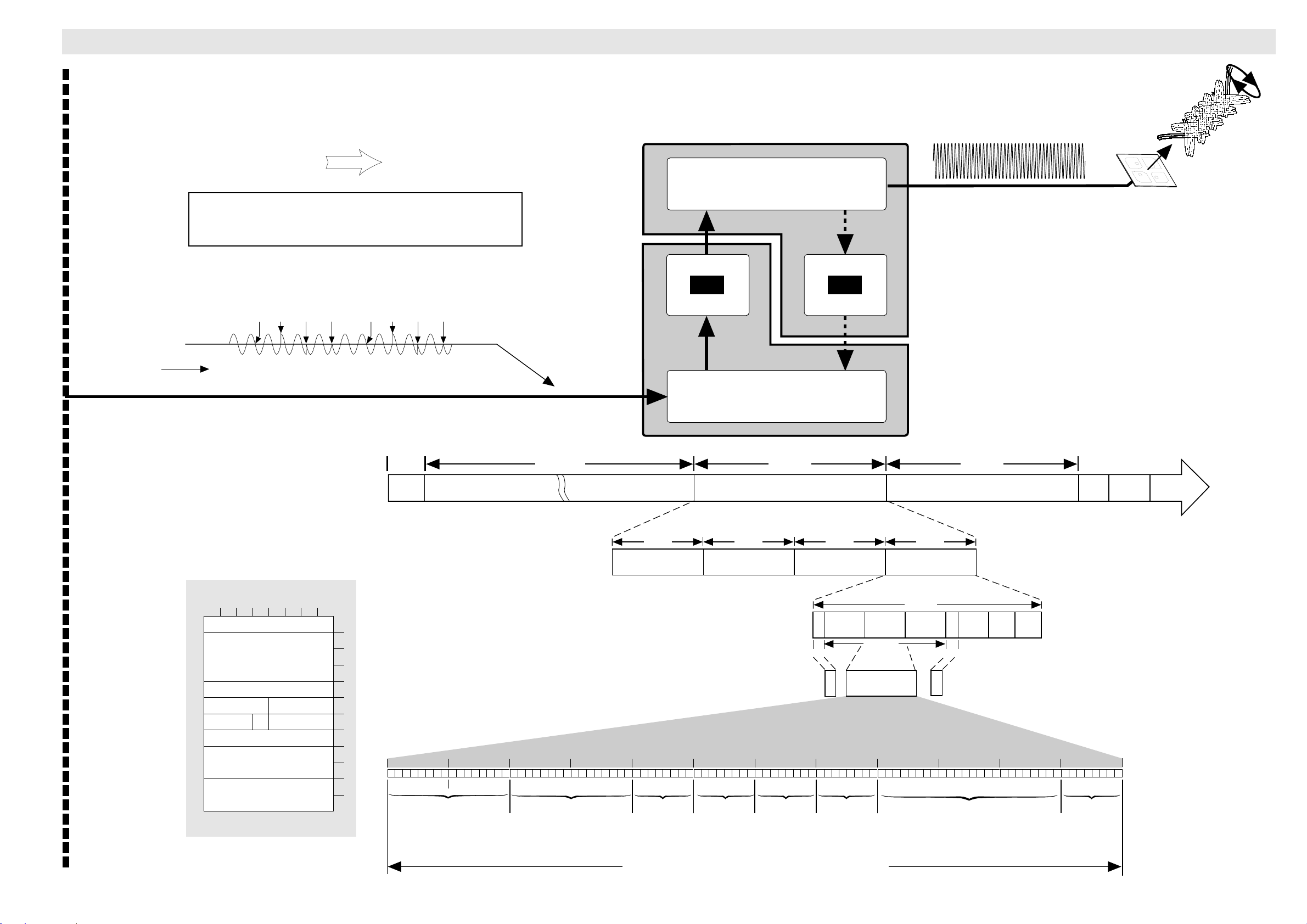
System DescriptionSystem Description Clearing
System Description
ADE
Right Hand Circular
Return Direction
MES LES
SCPC channel (Single Carrier Per Channel)
In-band Signalling Mode (CLEARING)
RF Units
f = 1626.5 - 1660.5 MHz
Duplexer
polarized RF signal
OQPSK Encoded Signal
(OQPSK = Offset Quadrature Phase Shift Keying)
0° +90° +270° +180°
0° +90° +270° +180°
HPA
LNA
t
Combiner/splitter
n x 240 ms 240 ms 240 ms24 ms
SIGNALLING UNIT – SU
8 7 6 5 4 3 2 1
cause class cause location
spare cause value
MSB
BIT No.
Message type
MES ID
LES ID
coding
std.
spare
MES transmit
channel number
CCITT CRC
M10
CHANNEL RELEASE
8A
LSB
END OF
DATA
192 bits
60 ms 60 ms 60 ms 60 ms
SU
SUBFRAME - 4
1
2
3
4
5
6
7
OCTET No.
8
9
10
11
12
Octet No. 12 Octet No. 11 Octet No. 10 Octet No. 9 Octet No. 8 Octet No. 7 Octet No. 6 Octet No. 5 Octet No. 4 Octet No. 3 Octet No. 2 Octet No. 1
1 0 1 0 1 0 1 0 1 0 1 0 1 0 1 0 1 0 1 0 1 0 1 0 1 0 1 0 1 0 1 0 1 0 1 0 1 0 1 0 1 0 1 0 1 0 1 0 1 0 1 0 1 0 1 0 1 0 1 0 1 0 1 0 1 0 1 0 1 0 1 0 1 0 1 0 1 0 1 0 1 0 1 0 1 0 1 0 1 0 1 0 1 0 1 0
CF
H
(CYCLIC REDUNDENCY CHECK)
CCITT CRC
3B
H
21
H
MES TRANSMIT
CHANNEL NUMBER
4C
H
00
H
SPARE
IN-BAND SIGNALLING FRAME
SUBFRAME - 3
11
H
SPARE
CODING
STANDARD
SU
VALUE
CAUSE
1920 bits
00
H
CLASS
CAUSE
CAUSE
SU
SUBFRAME - 2
FLUSH
8
bits
DUMMY
6 bits
09
LES ID MES ID MESSAGE
LOCATION
SU1SU1
384 bits
96 BIT
SIGNALLING UNIT
H
IN-BAND SIGNALLING FRAME
SU
SUBFRAME - 1
60 ms
SU1
8
bits
SUB
32 bits
FLUSH
1920 bits
* UW
24 bits
Before FEC
coding
DUMMY
6 bits
9F
H
CW
24 bits
* Unique Word:
0111 1000 1001
for 1st subframe, and
1000 0111 0110
for 2nd, 3rd and 4th
subframe (compliment)
BIT
TIMING
64 bits
8A
H
TYPE
CONTIN.
WAVE
96 bits
SUB-BAND
SIGNALLING
CHANNEL
Saturn Bp Portable – Technical Manual
SIGNAL UNITS = 12 "OCTETS" = 96 BIT SIGNALLING UNIT.
EXAMPLE: SCPC "IN-BAND SIGNALLING" MODE (CHANNEL RELEASE)
21
Page 24
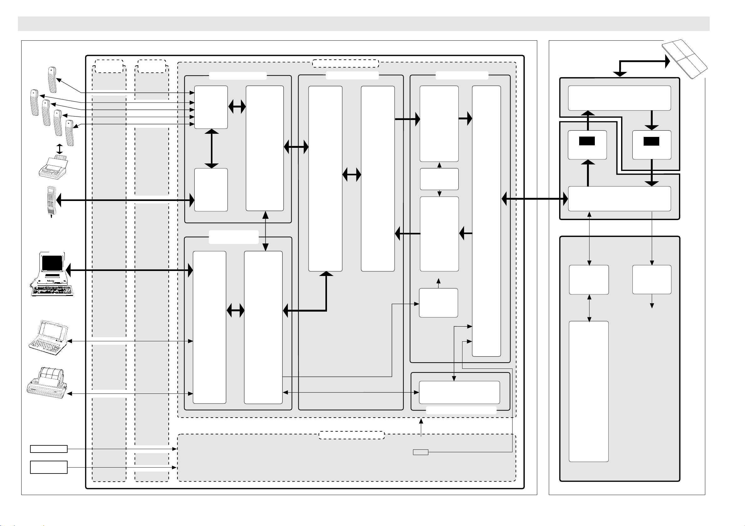
DiagramsDiagramsBlock Diagram
Diagrams
Antenna UnitMain Control Unit
External
Connectors
Telephone
or Telefax
(TEL. 2-5)
DIAL 00+INTL
TEL . NO . + f
1
2
3
4
5
6
7
8
9
0
*
#
DEL
FUNC
ALPHA
ENTER
MORE/
HELP
SHIFT
LES
ON/OFF
Display
Handset
DTE
(Modem)
Internal
Connectors
Telephone
or Telefax
(TEL. 1)
DTE
(Modem)
Telephony Interface
Subscriber
Selection
&
Interface
AUX
&
Handset
Interface
Access & Control
Sub-system
PCM
Codec
64 kbps
Data
Processor
&
Memory
Main Control Board
DSP Sub-system
DSPs
(Digital Signal
Processors)
Communication
with Data
Processor.
Voice PCM and
FAX coding.
Frame
assembly/
disassembly.
Scrambling/
descrambling.
FEC coding.
TX IF
2.5 MHz
ASIC
(Application
Specific
Integrated
Circuit)
Generates
modulated
TXIF
signal.
Demodulates
RXIF signal.
FEC decoding.
RX IF
12 MHz
RF Sub-system
Up-
converter
&
Transmitter
Upconverts
TXIF signal to
L-band TX
signal.
Amplifies TX
signal.
Local
Oscillator
1455–1489 MHz
Down-
converter
&
Receiver
Downconverts
L-band RX
signal.
Amplifies RX
signal.
Combiner/
splitter
TX
1626.5–
1646.5 MHz
RX
1530–
1559 MHz
RF Units
Receiver
Transmitter
HPA
High Power
Amplifier
Serial
Data
Interface
Duplexer
Separates RX and TX bands
LNA
Low Noise
Amplifier
Combiner/splitter
Combines/separates RF
signals and control signals
Control &
Monitoring Data
Voltage
Regulator
+28
VDC
RF Sub-
system
Power
Data
5/10 MHz
ADE supply
+28 VDC
+ 5 VDC
+15 VDC
PC
Buffers
&
UARTS
Access & Control.
Traffic handling.
User equipment
handling.
Alarm & Supervision.
T est & Diagnosis.
22
AC Mains
DC
Supply
90-276 VAC
47-400 Hz
11-34 VDC
Printer
Tx off
Data
DC/DC Power Board
Outputs:
Transmitter/receiver
&
Filters
Antenna Control Modem
+72 V
+38 V
+28 V
±
12V
+7 V
+5 V
GND
Data
Processor
HPA output
control.
Power monitor
supervision.
Burst duration
supervision.
Antenna Control Board – ACB
Saturn Bp Portable – Technical Manual
Page 25
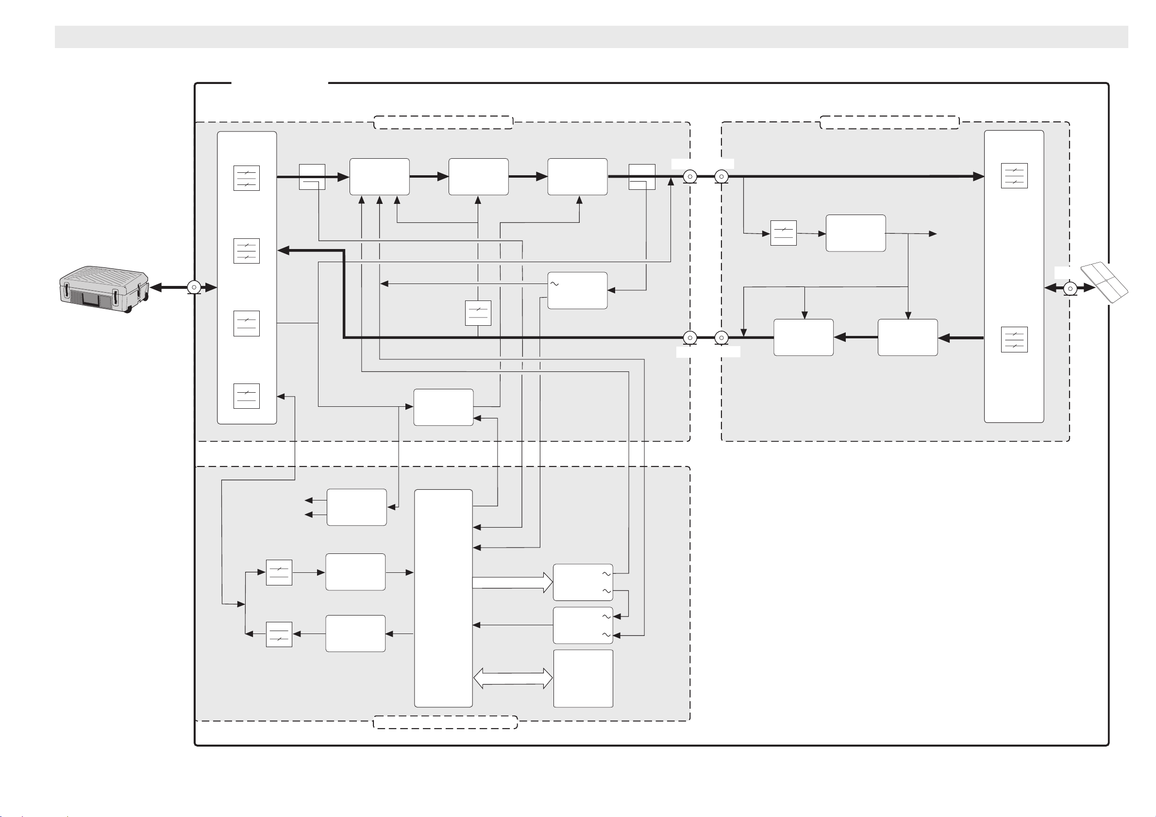
DiagramsDiagrams Antenna Unit Interconnection Diagram
Diagrams
Antenna Unit
RF Transmitter RF Receiver
Case w/
Main Control Unit
TRX
Combiner/
Splitter
TX
RX
+28V
DATA
Level
Regulator
(ALC)
+12 V
POWMON
POWREF
Tx Supply
Driver HPA
Power
Detector
+28 V
TXOUT
RXIN
TXIN
RXOUT
Amplifiers
&
Filters
+28V / +12V
Converter
Duplexer
1625.5 -
1660.5 MHz
+12 VDC
ANT
LNA
1525 -
1559 MHz
+15 V
+5 V
Voltage
Regulator
Data
Modulator
Data
Demodulator
+28 V
(*STATUS
function
message)
TXD
CPU
RXD
Antenna Control Board – ACB
*TXENABLE
*TXINP
*TXOUT
DACs
Comparator
QUART
Saturn Bp Portable – Technical Manual
23
Page 26
Telephone 1 (or Telefax)
Telephone 2 (or Telefax)
Telephone 3 (or Telefax)
Telephone 4 (or Telefax)
TEL
C
D
E
F
G
H
J
External
Connectors
TEL-2A
TEL-2B
TEL-3A
TEL-3B
TEL-4A
TEL-4B
TEL-5A
TEL
J1
2
3
4
Internal
Connectors
TEL-1A
TEL-1B
J10
11
23
10
22
9
21
8
J15/P2
A33
A32
A31
A30
A29
A28
A27
A26
A25
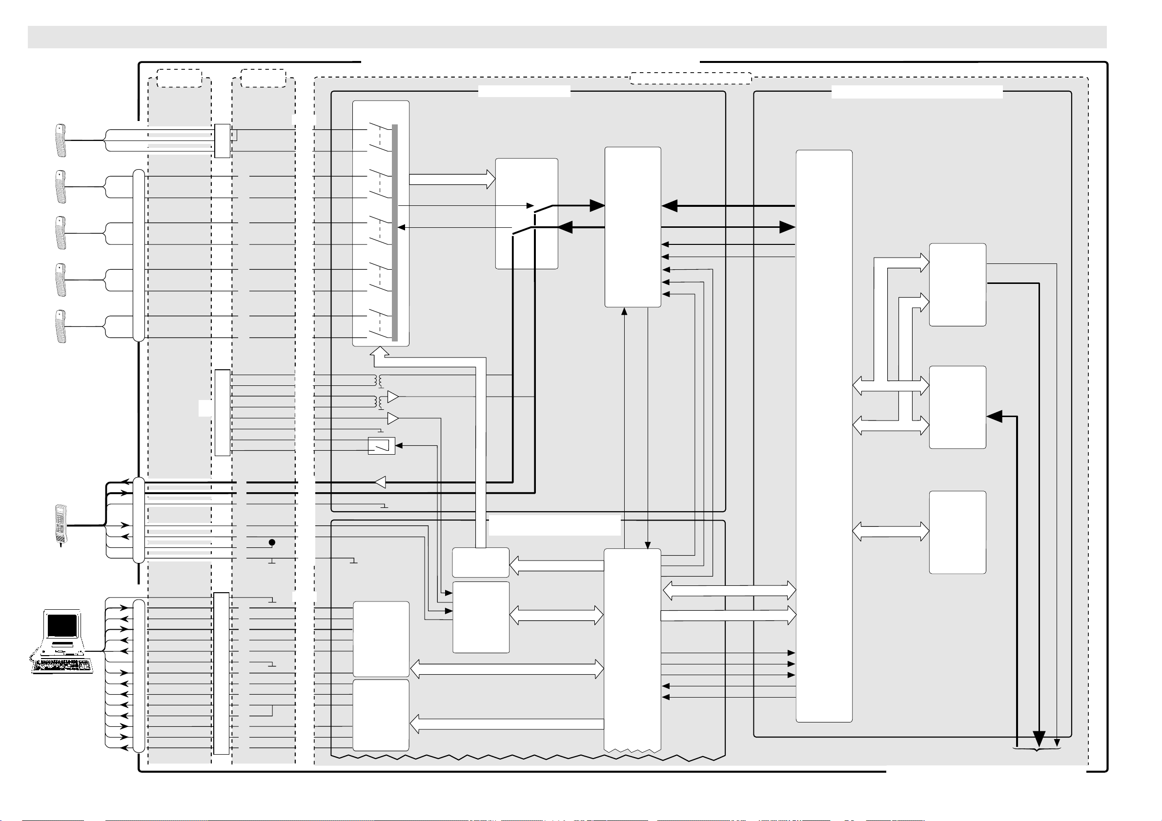
MAIN CONTROL UNIT – INTERCONNECTION DIAGRAM PAGE 1
Main Control Unit Board
Telephony Interface
T elephone Interface
& Relay Circuits
IL (0:5)
TXS
RXS
Codec
Selection
Circuits
VFRO
VFRI
PCM
Codec
DRI
DTI
SCLK_OUT
F_SYNCI
-CDC_SEL
CDC_CLK
RESET
Digital Signal Processing Sub-system
TX-SAMBA
&
D/A
~ 2.5 MHz
Converter
DiagramsDiagramsMCU Interconnection Diagram
Diagrams
TXMUTE
TXIF
Telephone 5 (or Telefax)
HANDSET
DIAL 00+INTL
TEL . NO . + f
1
2
3
4
5
6
7
8
9
0
*
#
DEL
FUNC
ALPHA
ENTER
MORE/
HELP
SHIFT
LES
ON/OFF
Display Handset
PC
(Data)
K
E
G
F
B
C
D
A
DTE
N
F
B
J
K
C
L
A
H
E
M
D
P
R
TEL-5B
SCREEN (101)
TXD (103)
RXD (104)
RTS (105)
CTS (106)
DSR (107)
GND (102)
DTR (108)
DCD (109)
RI (125)
TXCLK (DCE)
RXCLK (DCE)
TXCLK (DTE)
DRS (111)
DRS (112)
Not
used
AUX
J6
3
6
5
4
1
2
7
8
DTE
J7
1
2
3
4
5
6
7
20
8
22
15
17
24
23
25
20
J13
6
8
7
3
4
5
1
J10
19
7
3
15
16
4
17
2
14
6
18
5
24
12
EXOA
EXOB
EXIA
EXIB
EWA
EWB
MWA
MWB
HSA-RX
HSA-TX
HS-GNDA
TXD (103)
RXD (104)
12V
DIG GND
A24
A22
A21
A20
A19
A18
A17
A16
A15
A12
A10
A11
A06
A07
A05
J14/P1
B27
B26
B25
A20
B24
A27
A24
B23
A23
A26
A21
A19
B19
RS-232
Serial
Interface
RS-232
SWITCH (1:7)
RXE TXE
Access & Control Sub-system
(see also diagram page 2)
Telephony
Control
Latch
UART
CH. A
CPU
SCC1
CDC_TXCDC_RX
-RES_DSP
R-W
-HIP_2111
-TX_REQ
-RX_RDY
Data (0:15)
Address (1:2)
Master
Digital
Signal
Processor
RX-SAMBA
&
A/D
Converter
Digital
Signal
Processor
RXIF
~ 12 MHz
24
2/96
To/from RF Sub-system (see diagram page 2)
Saturn Bp Portable – Technical Manual
Page 27
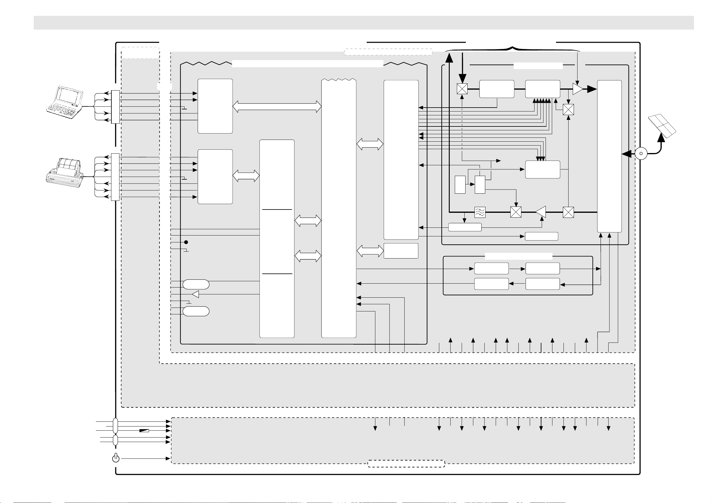
DiagramsDiagrams MCU Interconnection Diagram Cont’d
Diagrams
PC
Printer
PC
PRINTER
Internal
Connectors Cont’d
J8
RXD (104)
2
TXD (103)
3
GND (102)
5
RTS (105)
7
CTS (106)
8
P9
RXD (104)
2
TXD (103)
3
DTR (108)
4
GND (102)
5
DSR (107)
6
RTS (105)
7
CTS (106)
8
MAIN CONTROL UNIT – INTERCONNECTION DIAGRAM PAGE 2
Access & Control Sub-system (see also diagram page 1)
J14/P1
B21
B22
A22
B20
A25
B17
B18
A15
A18
B15
B16
A16
RS-232
Serial
Interface
RS-232
Serial
Interface
SCC2
UART
CH. D
CPU
Main Control Unit Board Cont’d
Latch
&
Buffer
* TX1 LOCK
BWCTRL1
BWCTRL2
BWCTRL3
SYNTDAT
SYNTCLK
TXSLCT
* TX2 LOCK
* LO LOCK
LOSLCT
Clock
Data
* OSC_LOCK
(* STATUS
function
message)
RXIF
~12 MHz
To/from DSP (see diagram page 1)
TXIF
15.84 MHz
X-tal
osc.
~2.5 MHz
~18.3
Tracking filter
MHz
x1
x4
BW=3 MHz
(PLL)
15.84 MHz
63.36 MHz
~12 MHz
RF Sub-system
~18.3
MHz
System
clock
LOREF
Up-converter
(PLL)
Local
oscillator
(PLL)
AGC
Amp.
~75 MHz
TXMUTE
1450 1484 MHz
1626.5 -
1660.5 MHz
Combiner/
splitter
1525 1559 MHz
A04
A03
A01
A02
A30
B30
A29
B29
A28
B28
+12V
Optocoupler
Optocoupler
UART
CH. C
UART
CH. B
SCC3
J17
A12 B12 A13 B13 A14 B13
-POWER-OFF
* RX SIGNAL
-TXOFF
Memory
ANT_TX
ANT_RX
KEY-ON
DC-LEVEL
Power detector
5 MHz
10 MHz
+72 V RET
+72V
-38V RET
Tx supply
Antenna Control Modem
Transmitter
Receiver
A39 A38 A11 A12 A09 A08 A07 A06 B05 A05 A03-04 A01-02
-38V
TEMP_RET
TEMP
-12V
Lowpass
Filter
Highpass
Filter
B09 B08 B07 B06 B03-04 B01-02
-12V RET
+5V
+5V RET
+12V
+12V RET
+7V
+7V RET
+28V
DATA
+28V
+28V RET
+28V RET
90 – 276 VAC
47 – 400 Hz
11 – 34 VDC
GND
–
+
A
B
C
A
B
ON
OFF
6.3 A slow
2/96
Saturn Bp Portable – Technical Manual
P1
15-16 13-14 11-12 1 2 3 4 5 6 19-20 21-22 23-24 25-26 27-28 29-30 31 32 33-36 37-40
AC & DC/DC Power Board
25
Page 28
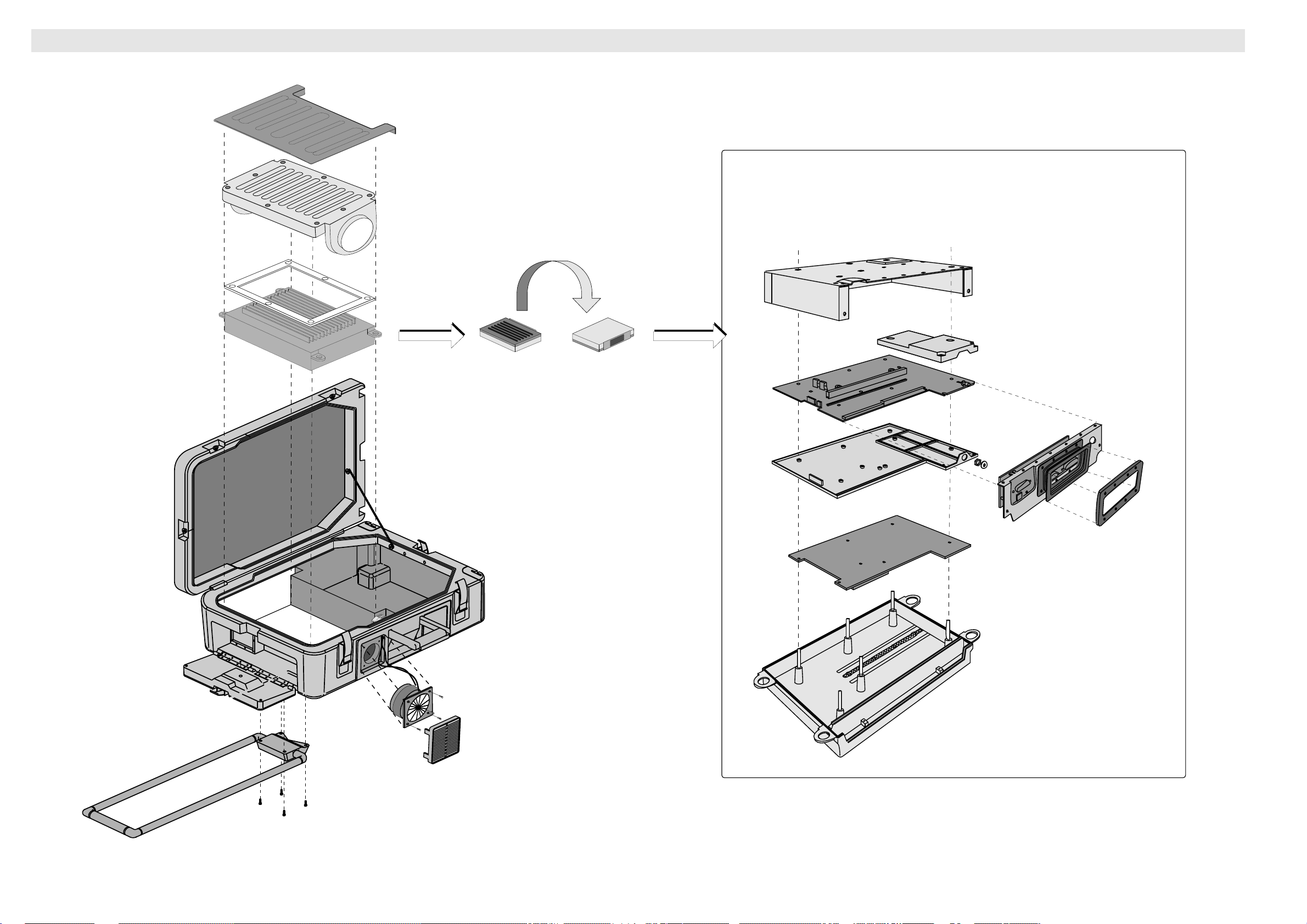
Exploded view – Saturn Bp Trunk
Cover
Airduct
MCU Main Parts
ServiceService
Service
Gasket
MCU
Box
RF Unit Cover
Main Control Board
Connector
Panel
Mounting plate
Frame
Power Board
26
Trunk
Pull handle
MCU Heatsink
Fan
Grid
Saturn Bp Portable – Technical Manual
Page 29
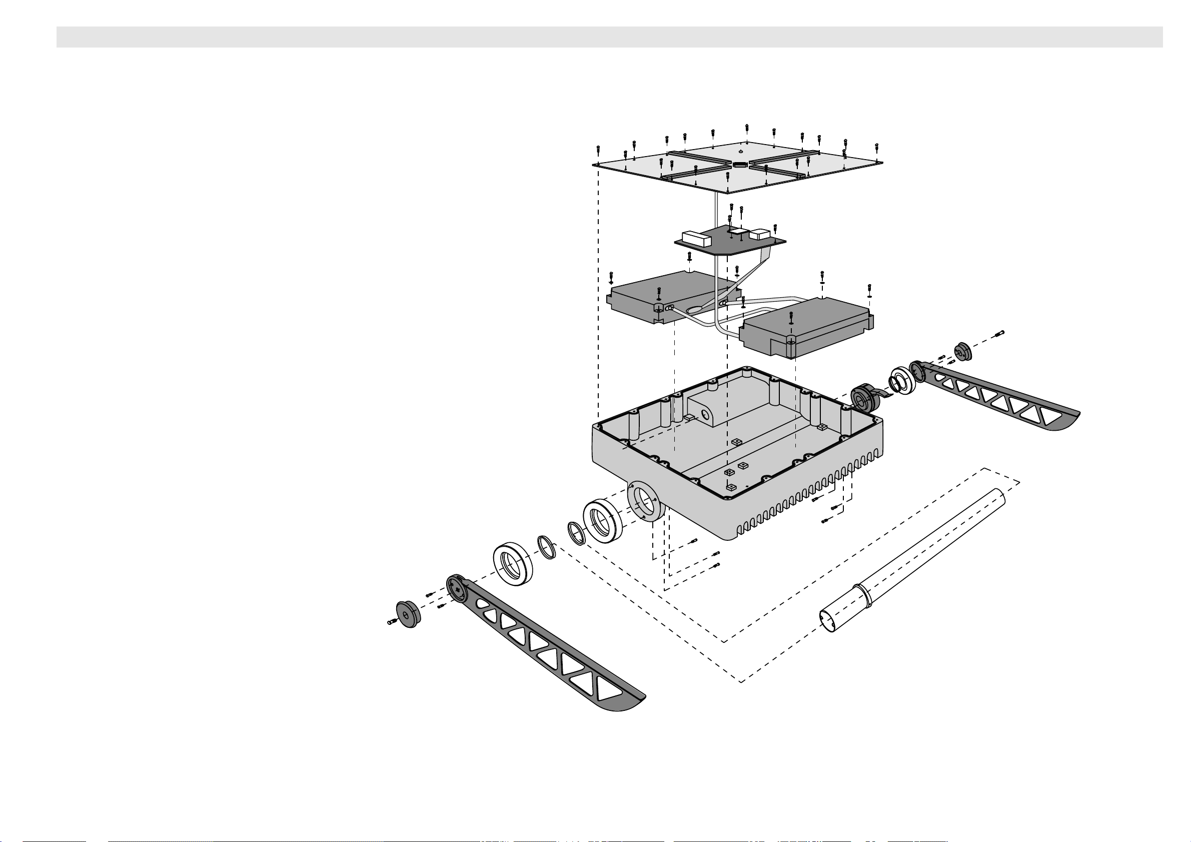
ServiceService Exploded view – Saturn Bp Transceiver
RX Unit
TX Unit
Antenna Control Board
Antenna Base Plate
Antenna Housing
Antenna Supporting Leg
Antenna Supporting Leg
Antenna Lock
Service
Saturn Bp Portable – Technical Manual
27
Page 30
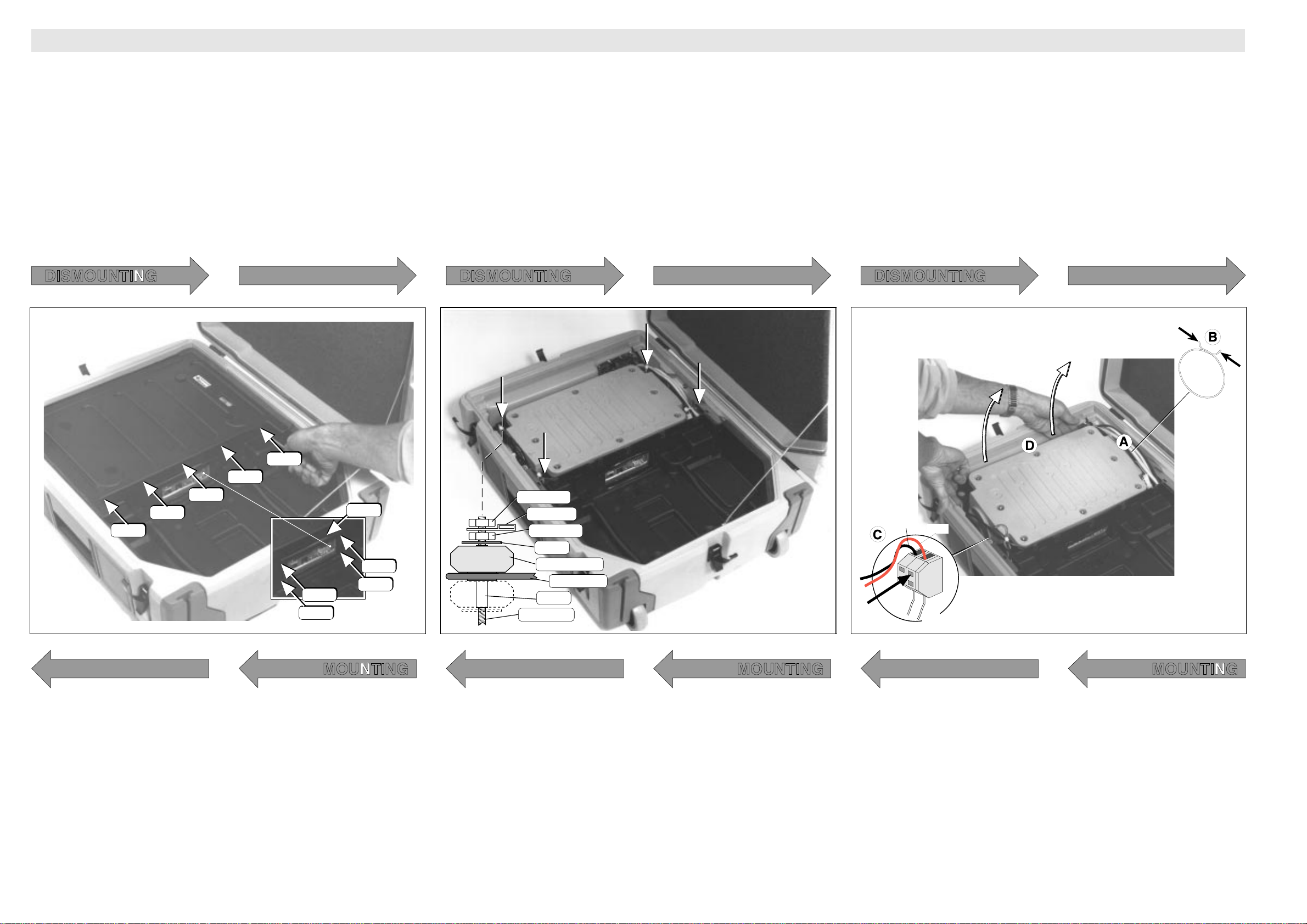
Replacing Trunk Parts
Red
Blue
Red
Blue
ServiceService
Service
1
• Open trunk and remove the contents. (Antenna sections,
MCU, cables etc.)
• Remove screws fastening the cover.
Note! 5 screws - M4x20 / 2.5 mm Unbraco. See figure!
• Lift off cover.
Note! May be a little tight because of edge sealing.
• Remove screws around Connector Panel. Remove frame.
Note! 4 screws - M3x6 pozidriv
2
• Loosen the first 4 nuts
Note! 8 mm socket
• Remove tie mount
• Loosen another 4 nuts
Note! 8 mm socket
• Remove washers
• Pull off rubber absorbers
Note! Replace bushings if they are pulled off along with absorbers
3
• (A) Move cables and wires carefully aside.
• (B) Squeeze hose clamp as illustrated and slide it towards
the trunk wall to disengage the MCU/fan channel from bellow.
• (C) Disconnect the fan by pushing a small screwdriver into
the terminal block as shown.
• (D) Lift out the MCU and place it alongside the trunk.
Start lifting the side edge as illustrated.
Note! Wires are still connected, be careful!
DISMOUNTING DISMOUNTING DISMOUNTING
2.5 mm
2.5 mm
2.5 mm
2.5 mm
2.5 mm
6 mm
6 mm
frame
MOUNTING MOUNTING MOUNTING
1414
14
• Replace the cover
Note! May be a little tight because of edge sealing.
• Mount the cover
Note! 5 screws – M3x6 pozidrive
• Mount the frame surrounding the Connector Panel
6 mm
6 mm
8 mm nut
tie mount
8 mm nut
washer
rubber absorber
"ear" on MCU
bushing
threaded bolt
1313
13
• Check that bushings slide down onto the bolts as illustrated.
• Mount the unit.
Note! Make sure that the “mounting ears” on the MCU are
mounted with rubber absorber, washer, nut, tie mount
and nut as shown on the drawing.
1212
12
At this point the MCU is to be placed in the trunk as follows:
• Place/push wires and cables against the trunk wall.
• Before lowering the unit fully down, slide the bellow (A)
onto the fan channel.
• Insert the locking ring (B)
• Connect the fan by pushing a small screwdriver into the
terminal block (C) andinsert wires as shown.
28
Saturn Bp Portable – Technical Manual
Page 31
ServiceService Replacing Trunk PartsReplacing Trunk Parts
M3x6M3x6M3x8
M3x8
M3x6 M3x6 M3x6
M3x6 M3x6
M4x6
M4x6
M4x6 M4x6
M4x6
M4x6
M4x6
locking spring
Service
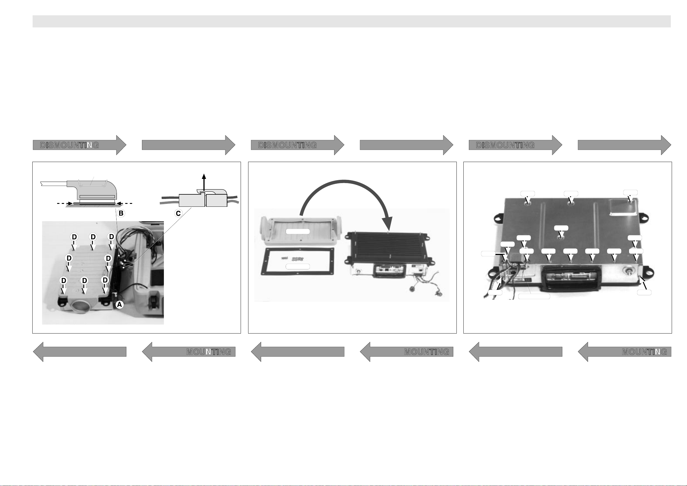
4
• (A) Release coax cable
• (B) Disconnect multiplug.
Remove locking spring and disengage locking plate as illustrated.
• (C) Disconnect remaining three plugs
Push up locking spring as indicated.
• (D) Unscrew 8 nuts an remove washers.
Note! 7 mm socket
5
• Lift off airduct
• Remove packing carefully.
6
• Turn the MCU upside down.
• Remove the large screws fastening the enclosing box
Note! 7 screws – M4x6
• Remove the screws fastening the locking spring
Note! 2 screws – M3x8 with large washers
• Remove remaining bottom plate fastening screws
Note! 7 screws – M3x6 with small washers
• Lift off the box
Note! Be aware of the Connector plate packings
DISMOUNTING DISMOUNTING DISMOUNTING
Release
Press
to lock
locking spring
Press to
release
MOUNTING MOUNTING MOUNTING
1111
11
• (D) Place the washers in the recesses and mount the nuts
Note! 7 mm socket
• (C) Interconnect the three plugs
• (B) Mount multiplug and lock with locking plate and spring
• (A) Mount coax cable
Note! Make sure locking hooks catch.
airduct
gasket
1010
10
• Turn the unit around
• Place the packing in correct position
• Place the airduct in correct position
99
9
• Replace the enclosing box
Note! Make sure all packings and bushings are correctly
positioned. See previous step.
• Mount the large screws fastening the box
Note! 7 screws – M4x6
• Mount the locking spring
Note! 2 screws – M3x8 with large washers
Saturn Bp Portable – Technical Manual
• Mount the remaining box fastening screws
Note! 7 screws – M3x6, with small washers
29
Page 32
Replacing Trunk Parts
Sil pad
MCU heatsink
ServiceService
Service
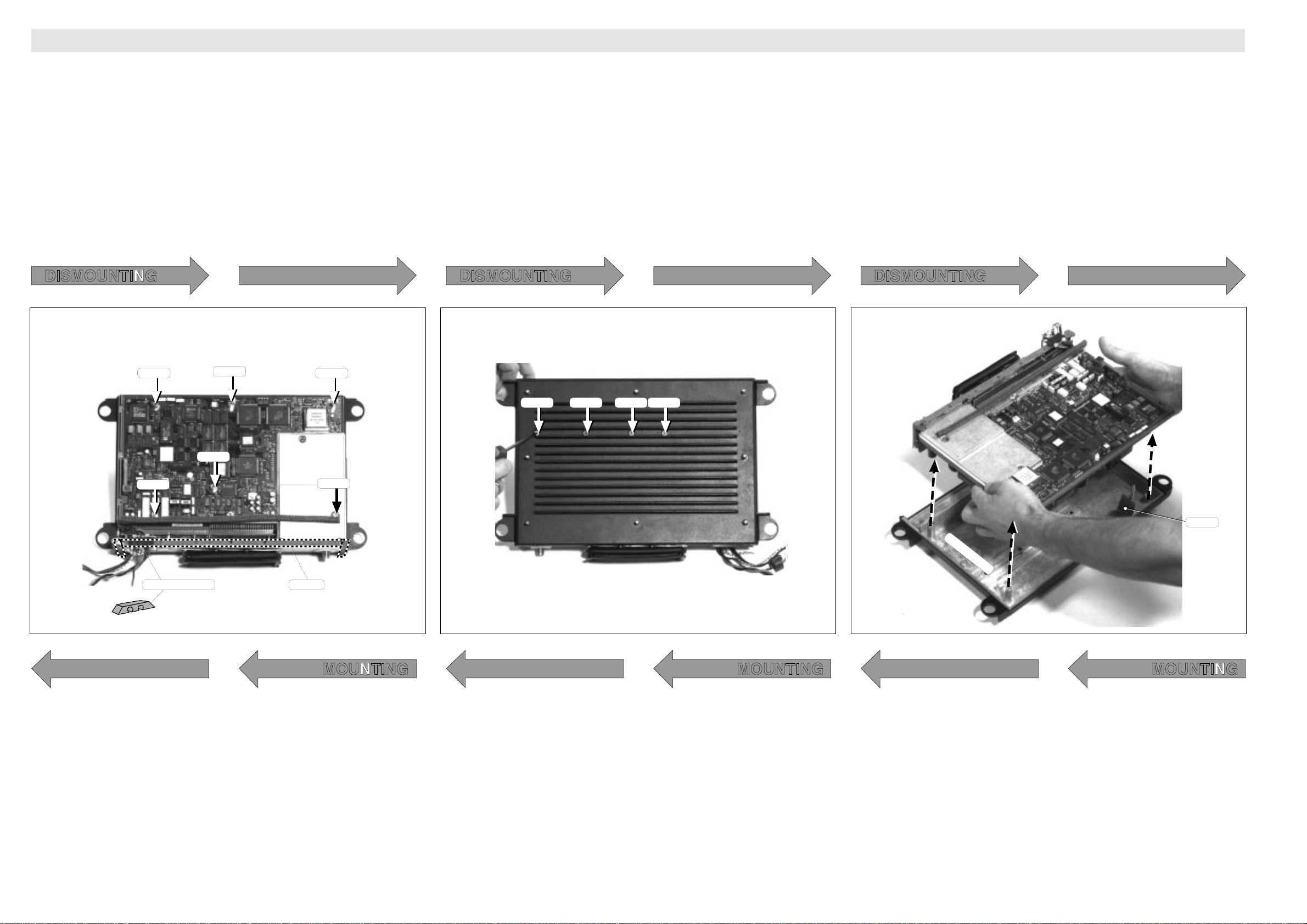
7
• Unscrew 6 standoffs (spacers)
Note! 3 sizes – 12 mm/16 mm/22 mm
7 mm spanner. See figure!
8
• Turn around the MCU
• Remove 4 unbraco screws
Note! M4x12 – 3 mm unbraco key
9
• Holding the unit together, turn it upside once more
• Lift up/out electronic unit including main circuit board (top
side) and power supply (bottom side)
Note! Save the small SIL pad protecting the spool on the
power supply from being damaged by the fastening
screw.
DISMOUNTING DISMOUNTING DISMOUNTING
16 mm
16 mm
22 mm
16 mm
M4x12 M4x12 M4x12 M4x12
16 mm
12 mm
gasketsbushing insulator
MOUNTING MOUNTING MOUNTING
88
8
• Turn the unit again
• Mount 6 standoffs (spacers)
Note! 3 sizes – 12 mm/16 mm/22 mm
7 mm spanner! See figure!
30
77
7
• Holding the unit together, turn it carefully around
• Mount 4 unbraco screws
Note! M4x12 – 3 mm unbraco key
66
6
• Place MCU heatsink with cooling fins down as shown
• With the Main Control Board up, lower the electronic unit
carefully down onto the bolts.
Note! Make sure that the bolts do not damage the electronics.
Note! Make sure that the Sil pad is positioned between the
bolt and the spool on the Power Board.
Saturn Bp Portable – Technical Manual
Page 33
ServiceService Replacing Trunk PartsReplacing Trunk Parts
Service
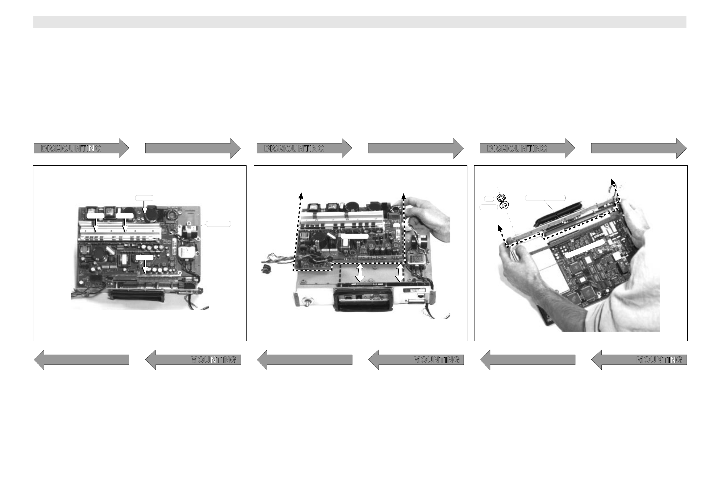
10 Power Board
• Turn the unit upside down.
• Cut wire ties
Note! Observe their positions
• Unscrew the board
Note! 4 screws – 2 sizes (M4x6 / M4x25 unbraco, 3 mm key).
See figure!
11
• Pull out the Power board
12 Main Control Board
• Turn the unit upside down.
• Cut or loosen wire ties
(If Power board has not already been dismounted)
• Unscrew the coax receptacle
Note! Nut and lock washer
• Slide the Connector Panel carefully off the Main Control
Board.
Replacing the DSP PROM, refer to step 14.
DISMOUNTING DISMOUNTING DISMOUNTING
Connector Panel
M4x25 M4x25
M4x6
Nut
Washer
fan plug
55
5
• Mount the Power board
Note! 4 screws - 2 sizes (M4x6 / M4x25 unbraco, 3 mm
nøkkel) See figure!
• Connect the fan plug
M4x6
Power Board
Main Control Board
MOUNTING MOUNTING MOUNTING
44
4
• Turn the unit upside down.
• Push the Power Board into position.
Note! Mind the edge connector.
33
3
• Push the Connector Panel carefully into position.
Note! Mind the edge connector.
• Mount the coaxial receptacle.
Note! Nut and lock washer
• Fasten wires with ties as prior to dismounting
Saturn Bp Portable – Technical Manual
31
Page 34
Replacing Trunk Parts
ServiceService
Service
13
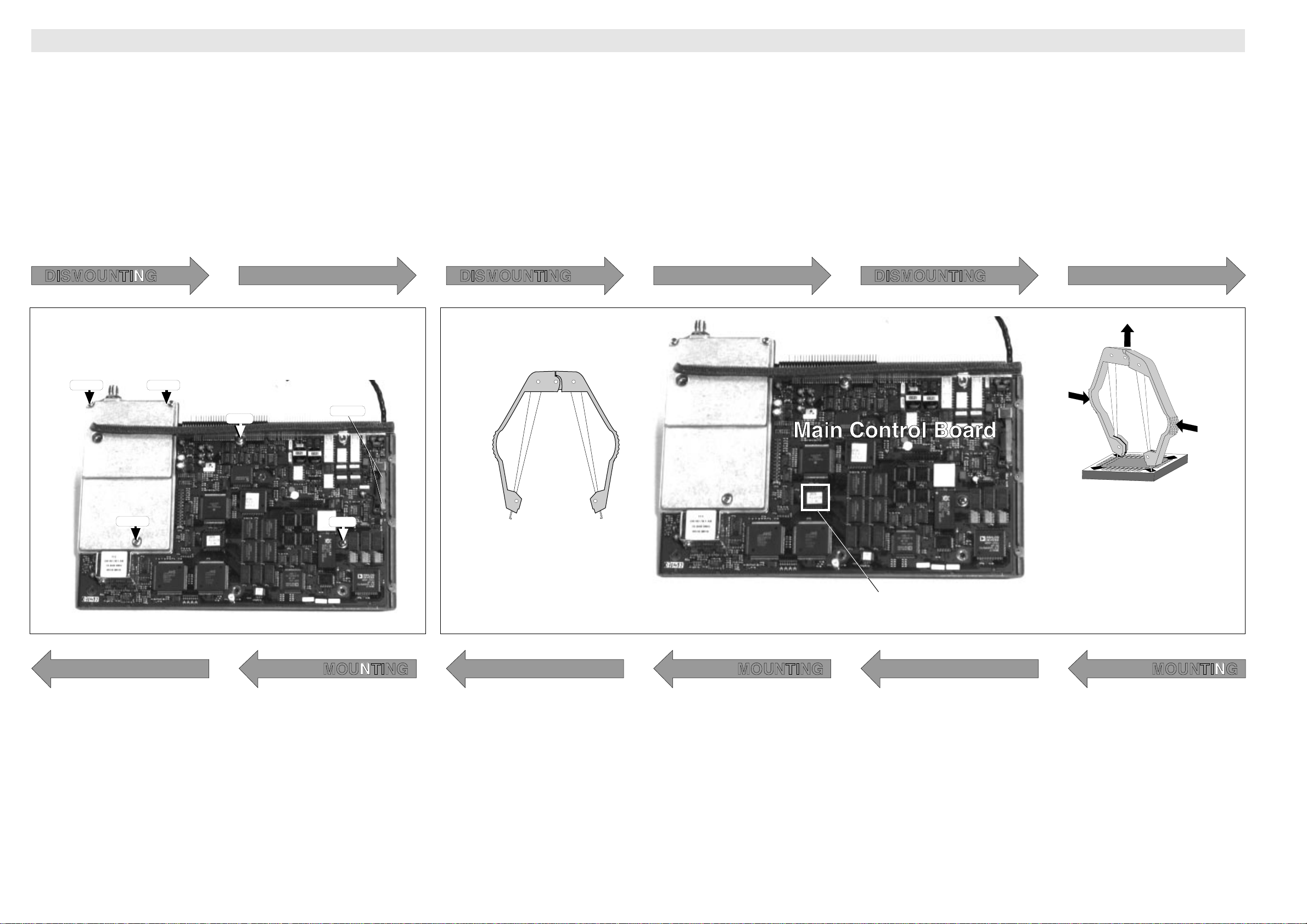
• Remove the clamps pressing the IC against the cooling plate
(Note! Save the Sil pads
• Remove the screws fastening the RF Unit cover.
Note! 3 screws - 2 sizes (M3x16 / M4x10). See figure!
• Remove the screws fastening the Main Control Board.
Note! 2 screws – M4x6. See figure!
The Main Control Board may now be replaced.
14 Replacing the DSP PROM
Tools required:
• PLCC extractor
• Wrist strap
• Follow the instructions in steps 1 – 8 of the dismounting
procedure.
• Locate the DSP PROM
• Place the PLCC extractor diagonally over the PROM as
shown in the figure.
• Carefully pull up the PROM from the socket.
DISMOUNTING DISMOUNTING DISMOUNTING
M3x16 M3x16
M4x6
M4x10
22
2
• Fasten the Main Control Board.
Note! 2 screws – M4x6. See figure!
clamps
PROM
Extraction of DSP PROM
M4x6
PLCC Extractor
DSP PROM
MOUNTING MOUNTING MOUNTING
11
1
IMPORTANT!
Use wrist strap when handling the new PROM!
• Mount the RF Unit cover.
Carefully tighten the screws evenly.
Note! 3 screws - 2 sizes (M3x16 / M4x10). See figure!
• Replace the clamps
Note! Insert a sufficient amount of Sil pads so as to
avoid tension on the IC.
32
• Align the PROM correctly and push it carefully down into
the socket.
Saturn Bp Portable – Technical Manual
Page 35

ServiceService List of Spare Parts
Service
Spare Parts – Saturn Bp
Description Nera Part Number
Basic parts:
AC cable 10 m QRPM911035
Antenna cable QRPM911030-1100
Antenna elements QSXK911910
Compass R906631
DC cable, 3m QRPM911036-3000
Fuses T6.3A Slow R906640/6.3S
Handset QDGS911901-2
Case:
Bellows QSCR101001
Bolt for wheel QSXA911135
Cable to MCU w/AC connector QRPM911040-0300
Cable to MCU w/connector and switch QRPM911042-0350
Cable to MCU w/DC connector QRPM911041-0450
Cable to MCU w/multiconnector QRPM911043-0500
Cable, MCU - handset QRPM911044
Coax cable QRPM911039
Fan for case QBKV101004-24
Fuse for MCU NGH24104/63
Fuse holder QNFN911001
Hinge for case QSXK911914
Lock w/key QSKY101001-2
Lock wo/key QSKY101001-1
Wheel QSLJ101001
Main Control Unit – MCU:
Fan for MCU QBKV101005-24
Printed board assembly, ICB QROF2199105
Printed board assembly, MCB QROF2199001-2
Printed board assembly, power QROF2199022-2
RF Transceiver:
ACB QROF2199023-2
Antenna, base plate QSXK911911
Antenna, stand, pole QSXA911126-2
Antenna, stand, pole QSXA911126-3
Cable, RX - base plate QRPM911049-0230
Cable, RX out - RX in QRPM911015-0090
Cable, TX - ACB QRPM911046-0160
Cable, TX out - TX in QRPM911015-0140
Rotation lock for antenna QSXK911920
RX QUFC911905
TX QUFC911904
Saturn Bp Portable – Technical Manual
33
Page 36
Number lists
and user lev.
1–
Region and
antenna ctrl
2–
Alarms and
messages
3–
System
information
4– ★
Terminal
config
5– ★
Bulletin
board data
6– ★
Installation
commands
7– ★
Enhanced
functions
8– ★
User level
Operator level ★
BB Status
(6)1 ★★
Randomize
advice
(6)2 ★★
Fwd channel
advice
(6)5 ★★
Return chnl
advice
(6)6 ★★
Sat.param.
advice
(6)7 ★★
Registration
status
(6)8 ★★
Active NCS
and spot id
(6)9 ★★
MES Id
(4)0 ★
MCU program
version
(4)1 ★
ACU type
ACU/PCU ver
(4)2 ★
DSP PROM
version
(4)3 ★
Boot PROM /
handset ver.
(4)4 ★
Enhanced
setup
(8)9 ★
Active
alarms
(3)0
Info
log
(3)1
Clear
cause log
(3)2 ★
Terminal
status
(3)3 ★
Menus:
Explanation of keys:
Reverts to
previous
position
Deletes
entry
Scrolls
down/
up
through
choices
Displays
additional
information
Arrow in the display
indicates that more
information is available:
Moves to the next
choice, or enters
the selected one
Selects FUNCTIONs,
and displays HELP
page if any
Current
ocean region
(2)0
Geographic
position
(2)1 ★
Nav area
(2)2 ★
IMO SAR
area
(2)3 ★
WMO area
(2)4 ★
ICAO SAR
area
(2)5 ★
Default LES
(5)0 ★
Contrast
adjust
(5)1 ★
Ring volume
adjust
(5)2 ★
Date and
time
(5)3 ★
Stand-alone
LES
(5)4 ★
LES
capabilities
(6)0 ★
Configure
ports
(7)0 ★
Incoming
call route
(7)1 ★
Commission
status
(7)2 ★
Various
config
(7)7 ★
Short number
list
(1)0
Last number
list
(1)1
Set user
level
(1)2
Set
password
(1)3 ★
Group id
numbers
(1)4 ★
☞
☞
ENTER
ENTER
☞
LIST
☞
☞
LIST
LIST
MORE/
HELP
☞
DEL
☞
☞
ESC
FUNC
☞
FUNC
☞
ESC
☞
Functions no.80 – 88 depend
on Saturn Mp configuration
Erase all
NV data
(7)9 ★★
SCAR
list
(1)9 ★★
Statistic
info
(3)4 ★★
Error
(3)5 ★★
Restart
cause
(3)6 ★★
Service level ★★
ServiceServiceService Level Functions
Service
General
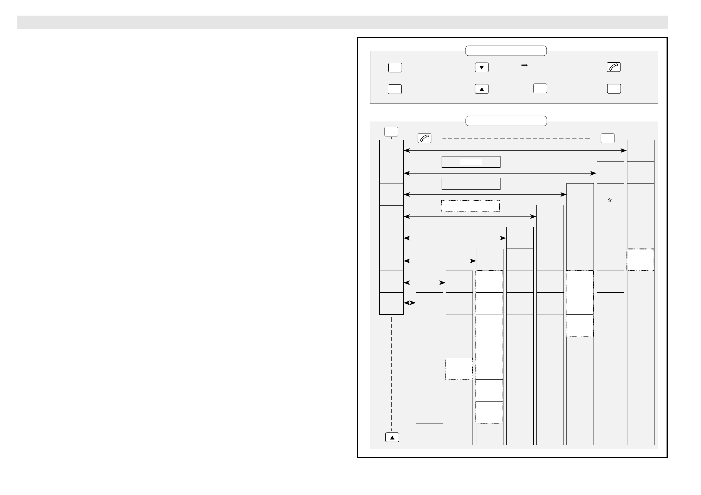
The diagram provides an overview of all Saturn
Bp functions, including five special "Service
Level" functions:
• Terminal Status, function no. 33 *
• Statistic info, function no. 34 *
• Error, function no. 35
• Restart cause, function no. 36
• Erase all NV data, function no. 79
The "Service Level" is selected with the "SET
(See "Setting User Level" in the Operator’s
USER LEVEL" function no. 12.
Manual)
The service level is set by keying 5 when selecting level, and entering the password 753951
when prompted.
(1=user level, 2=operator level, 5=service level).
Terminal Status (3)3 *
The Terminal Status function shows the status
of several test points monitored in the MCU.
The signals are marked with an asterisk (*) on
the MCU and Antenna Unit block diagrams.
They are also listed in the Terminal Status
Table.
Statistic Info (3)4 *
The Statistic Info function has no relevance for
service. It should only be used on request from
NERA.
configuration mistakes are made and the user
has difficulties in recovering the system. It
resets all configuration values to default.
Service printouts on PC
Information from the following functions can be
routed to a PC:
• Active alarms, function no. 30
• Info log, function no. 31
• Clear cause log, function no. 32
• Terminal Status, function no. 33 *
• Statistic info, function no. 34 *
Connection
A modem cable is connected between the DTE
port on the MCU and the Serial port of the PC.
A terminal emulator program, e.g. Procomm,
must be set up with the following port configuration:
Default 19.2 Kbps, 8-bit, no parity, 1 stopbit,
or as set with function no.86, see Saturn B Data
Service Operator’s Manual.
Error (3)5
The (SW) error function has no relevance for
service. It should only be used on request from
NERA.
Restart Cause (3)6
The Restart Cause function displays the reason
for the latest restart causes. It always contains
at least the Power up restart cause.
The function is a development tool, and has no
relevance for service. It should only be used on
request from NERA.
Erase all NV data (7)9
The Erase all NV data function can be used if
34
Saturn Bp Portable – Technical Manual
Page 37

Ref Display
Comments
No. Message
19 CALIBRATING Fluxgate compass failure
FAILURE
20 TX POWER OFF Main Control Unit failed to turn off transmitter in antenna.
FAILURE
21 MCU CARRIER Main Control Unit carrier not received by transmitter
MISSING in antenna.
22 HPA CARRIER Carrier not sent by antenna transmitter.
NOT SENT
23 MCU BURST Main Control Unit carrier not received by transmitter
MISSING in antenna.
24 HPA BURST Carrier not sent by antenna transmitter.
NOT SENT
25 PRINTER Printer programmed in Main Control Unit (MCU), but fails
NO RESPONSE to respond.
27 PC TELEX PC output programmed in Main Control Unit (MCU), but telex
NOT READY fails to respond.
28 GEO POSITION Geographic Position is not entered in due time.
NOT SET
29 NEED VERSION Wrong software version loaded in Main Control Unit (MCU), or
XX.XX wrong BOOT PROM version.
30 FUNCTIONALTY Enhanced function inconsistency
IS LOST
31 TRAFFIC LOG Traffic log erased.
DATA LOST
32 ANTENNA INIT No communication with antenna.
FAILURE
ServiceService
Service
List of Alarm Messages
Ref Display
Comments
No. Message
0 RX LOCK Receiver synthesizer out of lock
FAILURE
1 ANTENNA LINK No communication with antenna.
2 TERMINAL ID ID PROM in Main Control Unit (MCU) defective.
3 TX DETECTOR Illegal initial transmitter output level detected in Antenna
4 TX MONITOR Illegal initial transmitter input level detected in Antenna
5 ACU 28 VOLT Antenna Control Unit (ACU) input power too low.
6 ACU EPROM Antenna Control Unit (ACU) EPROM defective.
FAILURE
CRC FAILURE
FAILURE Control Unit (ACU).
FAILURE Control Unit (ACU).
FAILURE
FAILURE
7 ACU RAM Antenna Control Unit (ACU) RAM defective.
8 DSP COMM. Digital Signal Processor - CPU communication failure.
9 ALONE LES Default Standalone LES preselected.
10 DISTRESS LES Default Distress LES preselected.
11 STAND ALONE Standalone LES operative.
12 CALL REPEAT Due to heavy traffic. Minimum time between call requests
13 EEPROM CRC EEPROM in Main Control Unit (MCU) erased or defective,
14 NVRAM CRC NVRAM in Main Control Unit (MCU) erased or defective.
15 GROUP ID Error occurred when trying to register new group id.
FAILURE
FAILURE
PRESELECTED
PRESELECTED
LES USED
TIME LONG can be up to 17 minutes.
FAILURE or new software loaded.
FAILURE
FAILURE
16 DISTRESS UNIT Distress Alarm defective or not connected, or wrong
FAILURE address programming.
17 ANT.RESET No response to antenna reset.
FAILURE
18 ACU/MCU TYPE
MISMATCH
Saturn Bp Portable – Technical Manual
Wrong antenna type connected to Main Control Unit (MCU).
35
Page 38

List of Start-up Messages
List of Terminal Status Messages
ServiceService
Service
Ref Display
Comments
No. Message
0 PLEASE WAIT
1 CPU FLASH ID
2 CPU BURN ERR
3 CPU RAM ERR Cannot start system: hardware error.
4 DSP FLASH ID
5 DSP BURN ERR
6 VERSION ERR Illegal version of system program loaded, cannot start.
7 FLASH ERROR Incomplete system program, cannot start.
*
*
*
*
Only occurs at power up or when trying to load new software.
Cannot load new system program: problem with hardware.
Failure when loading new system program: hardware error.
Cannot load new DSP program: problem with hardware.
Failure when loading new DSP program: hardware error.
Ref No.
0 RX SIGNAL
1 TX1 LOCK
2 TX2 LOCK
3 LO LOCK
4 OSC LOCK
5 TX ENABLE
6 TX INPUT
7 TX OUTPUT
Display
Message
Comments
AGC active
TX1 synchronized
TX2 synchronized
Local oscillator locked
Oscillator locked
Transmitter on
Transmitter output low
Transmitter output high
8 BOOT PROM Illegal version of system program loaded, cannot start.
TOO OLD
*
Only occurs when trying to load new software.
8 NOT INUSE
36
Saturn Bp Portable – Technical Manual
Page 39

ServiceService List of Clear Causes
Ref No.
Display
Action Comments
Message
Service
Ref No.
Display
Action Comments
Message
0000/000 UNSPECIFlED
1021/000 OFF_HOOK TRY AGAIN Off Hook was not received from addressed MES
1081/000 TERMINAL ID The specified MES terminal number has not been
1141/000 PRIORITY PREEMPTION Pre-emption by MES user instruction to establish a
1142/000 DISTRESS PREEMPTION Offered shore-call cleared, pre-empted at MES by
1144/000 DISTRESS Attempted ship-call cleared, pre-empted at MES by
1145/000 PRIORITY Attempted ship-call cleared, pre-empted at MES.
REASON
TIMEOUT terminal within time limit.
MISMATCH installed
PREEMPTION Distress.
PREEMPTION
higher priority call
Distress.
12B1/005 UNSUCCESSFUL TRY AGAIN MES is clearing due to timeout. Waiting for assignment
CALL ATTEMPT from NCS during distress call.
12B1/008 LES TRY NEW LES Signal NUMBER from user carries an illegal CES ac-
UNDEFINED cess code parameter.
12B1/009 UNSPECIFIED TRY AGAIN Call rejected because a call set-up is already in
REASON progress.
12B1/010 UNSUCCESSFUL TRY AGAIN MES is clearing due to timeout. Waiting for assignment
CALL ATTEMPT from NCS during ship call.
12B1/011 UNSUCCESSFUL TRY AGAIN Respond-channel is not tuned in time.
CALL ATTEMPT
12B1/012 BUSY WITH TRY LATER Control did not grant access to terminal due to
CALL conflicting ship call.
12B1/013 BUSY WITH TRY LATER Control did not grant access to terminal due to
CALL conflicting shore call.
11D1/000 UNDEFINED TRY AGAIN Invalid information from MES; Service-Nature,
REASON -Type or Channel Param.
11D2/000 INCORRECT TRY AGAIN The “service address” information received from
NUMBER MES is invalid
11D3/000 INCORRECT TRY AGAIN The “service address” received from MES is currently
NUMBER undefined
11D4/000 CREDIT CARD TRY AGAIN Credit card information received from the MES is
DATA INVALID invalid
1201/000 SIMPLEX CALL MES is acknowledging the receipt of a simplex call
SUCCESSFUL
1261/000 SIMPLEX CALL Acknowledge of a simplex call which is possibly
UNSUCCESSFUL unsuccessfully received.
1262/000 DISTRESS Telephony ‘Distress Test’ call cleared after 120s
TEST TIMEOUT
12B1/001 DIAL TIMEOUT TRY AGAIN MES is clearing due to timeout of timer TS011
12B1/014 TOO FREQUENT TRY LATER Control did not grant access to terminal due to too
CALL ATTEMPT frequents request.
12B1/015 MES BUSY TRY LATER Control did not grant access to terminal.
12B1/020 TEMPERATURE System has failed. Ex. temperature alarm.
TOO HIGH
12B1/021 ANTENNA LINK The communication link to ACU has failed.
FAILURE
12B1/022 TX BURST TIME The tx burst duration has exceeded the maximum limit.
WAS TOO LONG
12B1/023 TX POWER OUT The tx power output level has exceeded the maximum
WAS TOO HIGH limit.
12B1/024 TX SYNTH. TX synth out of lock, call cleared or abandoned.
FAILURE
12B1/025 INITIALIZING System is not ready yet after start-up
TRY LATER
12B1/002 UNSUCCESSFUL TRY AGAIN MES is clearing (no SCPC signal received)
CALL ATTEMPT
12B1/003 UNSUCCESSFUL TRY AGAIN Channel is not tuned within allowed time limit.
CALL ATTEMPT
12B1/004 UNSUCCESSFUL TRY AGAIN MES is clearing due to timeout. Waiting for assign-
CALL ATTEMPT ment from NCS during shore call.
Saturn Bp Portable – Technical Manual
12B1/026 SPOT BEAM Spot beam selection is being performed
SELECTION
12B1/027 NETWORK DATA TRY LATER Bulletin board data (satellite channel information etc.)
VALIDATION is not yet verified
12B1/028 GROUP ID Group IDs are being updated
DOWNLOAD
37
Page 40

Ref No.
Display
Action Comments
Message
List of Clear Causes Cont’d
ServiceService
Service
Ref No.
Display
Action Comments
Message
12B1/029 ELEVATION Calculation of elevation zone is in progress
ESTIMATION
12B1/030 OCEAN REGION Ocean region registration is in progress
REGISTRATION
12B1/031 ANTENNA TRY LATER Antenna is not yet ready for use
INITIALIZING
12B1/033 NO SATELLITE REPOINT ANT. No satellite sync can be achieved
IS FOUND
12B1/034 CONFIGURING TRY LATER Antenna configuration is taking place
ANTENNA
12B1/035 FAST TRACK TRY LATER Antenna is tracking satellite
SATELLITE
12B1/036 SEARCHING TRY LATER Antenna is searching for satellite(s)
SATELLITE(S)
12B1/054 RESTRICTION CALL AGENT Access restricted due to Enhanced Function
DIAL 33# inconsistency.
12B1/055 ANTENNA CMD A command to the ACU was not accepted (4 times),
NOT ACCEPTED link restarted.
12B1/56 PEDESTAL CMD A command to the PCU was not accepted (4 times),
link restarted.
12B1/57 ANTENNA INIT Antenna initializing failed.
FAILED
12C1/000 UNSUCCESSFUL TRY AGAIN Scrambling Vector Ack was not received within allowed
CALL ATTEMPT time limit.
12C2/000 UNSUCCESSFUL TRY AGAIN Credit Card Accepted was not received within allowed
CALL ATTEMPT time limit.
12C3/000 UNSUCCESSFUL TRY AGAIN LES Connect message is not received by the MES
CALL ATTEMPT terminal within allowed time limit.
12B1/041 PRINTER NOT Power may be turned off, cable not connected, paper
RESPONDING empty or printer not selected/on-line.
12B1/043 UNSUCCESSFUL TRY AGAIN No acknowledge
CALL ATTEMPT
12B1/044 UNSUCCESSFUL TRY AGAIN No sync
CALL ATTEMPT
12B1/045 UNSUCCESSFUL TRY AGAIN No rx lock
CALL ATTEMPT
12B1/046 UNSUCCESSFUL TRY AGAIN No tx1 lock
CALL ATTEMPT
12B1/047 UNSUCCESSFUL TRY AGAIN No tx2 lock
12B1/048 UNSUCCESSFUL TRY AGAIN Missing or illegal channel
CALL ATTEMPT
12B1/049 UNSUCCESSFUL TRY AGAIN No authorization
CALL ATTEMPT
12B1/050 UNSUCCESSFUL TRY AGAIN Burst not sent
CALL ATTEMPT
12B1/051 NO TIME LEFT CALL AGENT Precharge terminal has run out of time. Must refill before
DIAL 230# call is possible.
12B1/052 UNACCEPTABLE Wrong PIN code entered.
PIN CODE
12D1/000 UNSUCCESSFUL TRY AGAIN Invalid “spot-beam ID” information from MES
CALL ATTEMPT
12D2/000 UNSUCCESSFUL TRY AGAIN The Scrambling Vector information received from MES
CALL ATTEMPT is invalid
1361/000 REWIND TRY AGAIN Above-decks equipment is about to “cable unwrap”
INTERRUPTION
1362/000 SIGNAL TRY AGAIN Long term interruption in reception.
INTERRUPTION
1363/000 REPOINTING TRY LATER PFC has commanded the Above-decks equipment to
ANTENNA repoint to a different Ocean Region.
1451 /000 TERRESTRIAL TRY AGAIN An appropriate terrestrial circuit is not currently
CONGESTION available at this LES.
1452/000 LES TRY AGAIN An appropriate channel unit and associated terrestrial
CONGESTION circuit, with ‘one-to-one’ connection, are not currently
available at this LES.
1541/000 PRIORITY Pre-emption of LES by a higher priority call.
PREEMPTION
1551 /000 LES TRY AGAIN An appropriate satellite channel is not currently
CONGESTION available at this LES.
1552/000 LES TRY AGAIN An appropriate tdm and/or tdma time-slot is not cur-
CONGESTION rently available.
38
Saturn Bp Portable – Technical Manual
Page 41

ServiceService List of Clear Causes Cont’d
Ref No.
Display
Action Comments
Message
Service
Ref No.
Display
Action Comments
Message
1581/000 SERVICE NOT TRY NEW LES LES is not equipped to provide the specified service.
PROVIDED
1591/1000 SERVICE NOT TRY AGAIN LES is equipped to, but not currently able to provide
AVAILABLE the service.
1592/000 CREDIT CARD TRY NEW LES Specified credit card type is not currently supported by
TYPE INVALID this LES.
15A1/000 MES NOT TRY NEW LES MES is not authorized for any service, except Distress,
AUTHORIZED via this LES.
15A2/000 SERVICE NOT TRY NEW LES MES is not authorized for specific requested service via
AUTHORIZED this LES.
15A3/000 CREDIT CARD Credit card data from MES rejected by the authorization
NOT ACCEPTED checking process.
15B1/000 UNDEFINED The call is cleared or rejected for a reason not currently
CAUSE defined.
15C1/000 UNSUCCESSFUL TRY AGAIN Channel Assignment message is not received within
CALL ATTEMPT allowed time limit.
15C2/000 UNSUCCESSFUL TRY AGAIN The service-address information is not received within
CALL ATTEMPT allowed time limit.
15C3/000 UNSUCCESSFUL TRY AGAIN Scrambling Vector message is not received within
CALL ATTEMPT allowed time limit.
15E1/000 FORCED LES is attempting to clear an MES which has sent an
RELEASE SCPC channel release message, but is found still to be
transmitting 5.12 s later.
1651/000 LES TRY AGAIN LES is rejecting the call because an appropriate channel
CONGESTION unit is not currently available.
1661/000 SIGNAL TRY AGAIN Interruption in reception of the MES carrier exceeding
INTERRUPTION allowed time limit.
16C1/000 UNSUCCESSFUL TRY AGAIN Telegraphy call cleared; MES carrier is not received
CALL ATTEMPT within time limit.
16C2/000 UNSUCCESSFUL TRY AGAIN An appropriate SCPC MES carrier is not received by LES
CALL ATTEMPT (at the commencement of the call) within the time limit.
1851/000 SATELLITE TRY AGAIN Appropriate SCPC channel is not currently available.
CONGESTION
18A1/000 MES-ID TRY NEW LES MES ID is not in the ‘Forward and Return MES ID’ cross
UNKNOWN reference table.
18B1/000 CALL The call is cleared or rejected for a reason not currently
REJECTED defined.
18E1/000 MES-ID USED The specified MES ID is in the “MES busy list” at the
BY OTHER MES NCS, listed as being busy with a call through the same
LES as that now requesting a “call announcement”
addressed to that MES.
15C4/000 UNSUCCESSFUL TRY AGAIN Neither Scrambling Vect. nor Serv. Address is received
CALL ATTEMPT within time limit.
15C5/000 UNSUCCESSFUL TRY AGAIN LES is clearing the call because the complete “credit
CALL ATTEMPT card data” info has not been received.
15C6/000 UNSUCCESSFUL TRY AGAIN Return Carrier Identifier message not received within
CALL ATTEMPT allowed time limit.
15C7/000 UNSUCCESSFUL TRY AGAIN MES Connect message is not received within the
CALL ATTEMPT allowed time limit.
15C8/000 UNSUCCESSFUL TRY AGAIN Telegraphy call cleared; MES Answerback is not
CALL ATTEMPT received within time limit.
15D1/000 UNSUCCESSFUL TRY AGAIN Channel Assignment message from NCS contains
CALL ATTEMPT inappropriate information.
15D2/000 MES-ID USED MES ID and channel number is cleared in the busy lists
BY OTHER MES at LES and NCS because a new call to/from this
MES is being set up, and thus any previous call to/from
this MES must have cleared.
1C61/000 UNSUCCESSFUL TRY AGAIN Telegraphy call cleared; MES Answer back is not received
CALL ATTEMPT within time limit.
1F01/000 SUBSCRIBER Normal clearing due to instruction from relevant terrestrial
ON HOOK circuit.
1F11/000 SUBSCRIBER Terrestrial called party is busy.
BUSY
1F21/000 NO ANSWER Appropriate off-hook signalling from the terrestrial called
party is not received within the allowed time limit
1F61/000 SUBSCRIBER TRY AGAIN Failure in the relevant terrestrial circuit.
LINE FAILURE
1F62/000 SUBSCRIBER Terrestrial network cleared the call before “MES connect”
ON HOOK was received by the LES.
Saturn Bp Portable – Technical Manual
39
Page 42

List of Terms
ServiceService
Service
AC Alternating Current
ACB Antenna Control Board
ADE Above Deck Equipment
ALC Automatic Level control
ANT Antenna
AOR-E Atlantic Ocean Region East.
AOR-W Atlantic Ocean Region West.
ASIC Application Specific Integrated Circuit
AU Antenna Unit, major part of MiniPhone
AUX Auxiliary
BDE Below Deck Equipment
BPSK Binary Phase Shift Keying
Bulletin Board system status information for MES
C Band band of radio frequencies from about 4.0 GHz to
6.0 GHz, used by Inmarsat links for the satellite/LES link.
CCITT International Telegraph and Telephone Consulta-
tive Committee
CES Coast Earth Station
Codec speech encoder/decoder
CPU Central Processing Unit
CRC Cyclic Redundancy Check
CTS Clear To Send
DAC Digital-Analogue Converter
dBW deciBels relative to 1 Watt
DC Direct current
DCD Data Carrier Detect
DI Destination Identification digits
Downlink radio link from the satellite down to stations on
Earth.
DSP Digital Signal Processor
DSR Data Set Ready
DSUB Data Sub-band, SCPC sub-band signalling.
DSUB Data Subminiature
DTE Data Terminal Equipment
DTR Data Terminal Ready
EEPROM Electrically Erasable Programmable Read Only
Memory
EIRP Equivalent Isotropically Radiated Power
EPROM Erasable Programmable Read Only Memory
FDMA Frequency Division Multiple Access
FIO Fax Interface Unit
GPS Global Positioning System, a satellite navigation
system.
HPA High Power Amplifier
Hz Hertz
ID Identification Digit(s)
IMN Inmarsat Mobile Number, a unique 9-digit number.
Inmarsat International Maritime Satellite Organisation
IOR Indian Ocean Region.
ISDN Integrated Services Digital Network, digital national
and international telecommunications network.
ITU International Telecommunications Union, international
organisation that oversees and compiles standards for
telecommunications.
KBPS KiloBits Per Second
L Band band of radio frequencies from about 1.5 GHz to
1.6 GHz, used by Inmarsat for the MES/satellite link.
Latitude distance north or south of the equator, measured
in degrees.
LED Light-Emitting Diode, semiconductor element that
emits light.
LES Land Earth Station, a station that interconnects fixed
telecommunications networks with the Inmarsat system;
may also be called a CES (Coast Earth Station) or a GES
(Ground Earth Station).
LES-SIG LES Signalling, SCPC mode for in-band signalling.
LESA Land Earth Station Assignment Channel
LESD LES Data, SCPC mode for data communications
LESI LES Interstation Signalling Channel, TDM channel
carrying signalling information to NCS.
LESV LES Voice, SCPC mode for voice communications
LHCP Left Hand Circular Polarization
LNA Low Noise Amplifier
LONG longitude
Longitude distance east or west of Greenwich meridian,
measured in degrees.
MCB Main Control Board
MCC Mobile Country Code
MCU Main Control Unit, major part of terminal; performs
all signal processing and message handling functions.
MES Mobile Earth Station, a user terminal for an Inmarsat
system; the Saturn M terminal is an MES for the InmarsatM system; MES may also be called SES (Ship Earth
Station) or, if on aircraft, AES (Aeronautical Earth Station).
MES-SIG MES Signalling, SCPC mode for in-band signalling.
MESCA MES Call Acknowledgement, random access
(Slotted Aloha) burst mode channel carrying acknowledgement messages for fixed-originated simplex calls.
MESD MES Data, SCPC mode for data communications
MESRP MES Response, TDMA channel carrying the
response information required for a fixed-originated call.
MESRQ MES Request, random access (Slotted Aloha)
burst mode channel carrying access request messages to
LESs for initiation of mobile-originated calls.
MESRR MES Registration channel, random access
(Slotted Aloha) burst mode channel carrying the Ocean
Registration messages required to route fixed-originated
calls.
MESV MES Voice, SCPC mode for voice communications
MHz MegaHertz
MID Maritime Identification Digits
NCRA Network Coordination Registration Acknowledge-
ment, TDM channel carrying responses to registration
messages transmitted by MESs.
NCS Network Coordination Station, station that supervises all messages and signals sent in the Inmarsat
system; one in each Ocean Region.
NCSA NCS Assignment, TDM channel carrying channel
assignment messages.
NCSC NCS Common, TDM channel carrying signalling
messages including call announcements, Bulletin Board
and forced channel clearing.
NCSI NCS Inter-station channel used by NCS to carry
signalling information to the LES.
NCSS NCS Spotbeam, TDM channel carrying spotbeam
identification numbers.
NMEA National Marine Electronics Association, US
industrial organisation whose activities include stipulating
standards for marine navigation systems.
O-QPSK Offset Quadrature Phase Shift Keying.
OCC Operation Control Centre, Inmarsat centre that
monitors entire Inmarsat system.
Ocean Region area of coverage of a single Inmarsat
satellite, from 70°N to 70°S; there are four: Atlantic East,
Atlantic West, Pacific, Indian.
OI Originating Identification digits
OSC Oscillator
PC Personal Computer
PCM Pulse Code Modulation, analogue-to-digital signal
conversion method.
PCU Pedestal Control Unit
PLL Phase Locked Loop
POR Pacific Ocean Region
Prefix service in Inmarsat-M, two-digit prefix to number
called, keyed in to stipulate special service, such as creditcard call.
PROM Programmable Read Only Memory
Protocol the internal rules in the system that enable
communications.
PSDN Packet Switched Data Network, terrestrial network
for packet data communications.
PSTN Public Switched Telephone Network, terrestrial
network for telephone, telefax and data modem services.
QUART Quad Universal Asynchronous Receiver/Transmitter, provides four interfaces between parallel data
circuits and serial data circuits.
RF Radio Frequency
RHCP Right Hand Circular Polarization
ROM Read-Only Memory, microchip memory that stores
programs and/or data.
RS 232 Serial Data Interface
RS 422 Serial Data Interface
RTS Request To Send
RX IF Receiver Intermediate Frequency
Rx Receive
RXD Receive Data
SAMBA TX/RX Up/down conversion between intermedi-
ate frequency and base band.
SCC Satellite Control Centre
SCPC Single Channel per Carrier
SDM (Inmarsat-M) System Definition Manual
SES Ship Earth Station
Spot Beam (Inmarsat-M) service that divides each Ocean
Region into sub-regions, each “spotlighted” by a beam
from the region satellite; permits increasing capacity of
system.
SU Signalling Unit, 96-bit data packets transmitted on
SCPC sub-band signalling channels, to conduct system
signalling.
SU Signalling Unit, data packets
TDM Time Division Multiplexing, method of allowing
several users to share the same channel.
TDMA Time Division Multiple Access
Terrestrial Network a fixed telecommunications network,
such as a telephone network or a data network, which
connects to the Inmarsat-M system at an LES.
TUP Telephone User Part of CCITT Signalling System No 7.
TX IF Transmitter Intermediate Frequency
Tx Transmit
TXD Transmit Data
UART Universal Asynchronous Receiver/Transmitter,
provides interface between parallel data circuits and serial
data circuits.
Uplink radio link from a station on Earth up to the satellite.
UTC Coordinated Universal Time, referenced to Green-
wich Mean Time (GMT)
UW Unique Word
VSUB Voice Sub-band, SCPC sub-band signalling.
WMO World Meteorological Organization
40
Saturn Bp Portable – Technical Manual
Page 43

Page 44

Nera ASA
Nera SatCom AS
Bergerveien 12, PO Box 91
N-1375 Billingstad, Norway
Tel: +47 67 24 47 00
Fax: +47 67 24 46 21
www.nera.no
 Loading...