

Nera Saturn BM Marine, Saturn BM Marine Class 2 Owner's Manual

Saturn Bm Marine
Class 2
Operator
`s
Manual
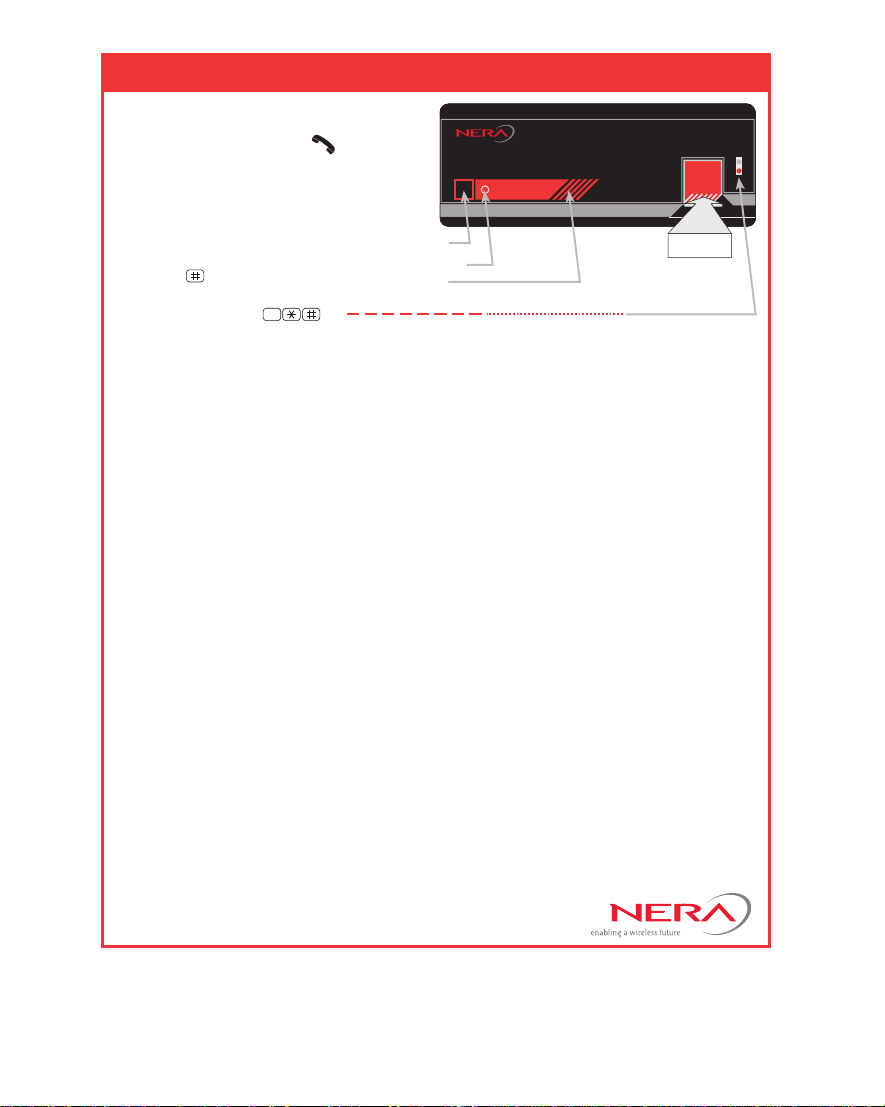
SATURN B - TELEPHONE DISTRESS CALL
TRANSMISSION
Saturn B
1 Lift telephone handset .
2 Lift flap over DISTRESS BUTTON.
Press and hold down
DISTRESS BUTTON for
at least 6 seconds.
3 Wait for dialing tone.
4 Press
your call. You can also
select LES: e.g.
-key to initiate
4
5 When the Rescue Co-
ordination Centre (RCC) Operator answers, speak clearly, and give the following message:
• MAYDAY MAYDAY MAYDAY
• THIS IS (ship’s name and identity) CALLING ON INMARSAT FROM
• POSITION (latitude and longitude, or relative to a point of land).
• MY INMARSAT MOBILE NUMBER IS (IMN for the Saturn Bm telephone you
are calling from) USING THE (Ocean Region) SATELLITE.
• MY COURSE AND SPEED ARE (course and speed).
• NATURE OF YOUR DISTRESS, for example:
• ASSISTANCE YOU REQUIRE.
• OTHER INFORMATION to help rescue units.
End your message by saying "OVER", which is the invitation for the RCC to reply.
> Fire/explosion > Listing > Abandoning ship
> Flooding > Sinking > Piracy attack
> Collision > Disabled > Medical service
> Grounding and adrift required
Reception:
ACKNOWLEDGE
PUSH BUTTON
ALARM INDICATOR
ALARM BUZZER
Transmission:
Indicator flashes slowly, then quickly after 6 seconds
DISTRESS
ALARM
ACKNOWLEDGE
DISTRESS
BUTTON
6 Follow the instructions from the RCC Operator, and when requested, replace the
handset to await further calls.
7 Keep the telephone line clear so that the RCC can call you back when necessary.
RECEPTION
• The ALARM BUZZER and ALARM INDICATOR are activated on all installed
Distress Alarms when a distress call is received.
• When answering the call, ALARM BUZZERS stop and ALARM INDICATORS
light steadily on all Distress Alarms.
• Pressing the ACKNOWLEDGE PUSH BUTTON where the telephone rings, stops buzzers
on all Distress Alarms. Pressing the button at other sites only stops the buzzer locally.
Doc. No. QLZB911014 Rev. A1 04/2001
Note! For further information on:
• Detailed operation, see "Distress Alarm".
• Distress Alarm setup, see "Configuring Ports".
•
Preferred Distress Land Earth Station, see "Selecting Default Distress LES".
• To check the operation of the Distress Alarm, see "Distress Test".

Chapter 1. Getting Started
Introduction........................................................ 1.1
Handset w/Display & Keypads........................... 1.7
Starting Up ........................................................ 1.8
Call from Display Handset ............................... 1.11
Call from Telephone ........................................ 1.12
Service Address Calls ..................................... 1.13
Terrestrial Network and Priority Calls .............. 1.14
Using Telefax .................................................. 1.15
Connector Panel.............................................. 1.16
1. Getting Started
Chapter 2. Operation
Using the Display Handset ................................ 2.1
Functions........................................................... 2.5
Selecting Ocean Region .................................... 2.8
Short Numbers .................................................. 2.9
Last Number Redialing .................................... 2.12
Active Alarms .................................................. 2.13
Info Log ........................................................... 2.14
Clear Cause Log * ........................................... 2.15
Terminal Status *............................................. 2.16
Setting User Level ........................................... 2.17
Selecting Default LES...................................... 2.18
System Information * ....................................... 2.19
Group Calls * ................................................... 2.20
Geographic Position * ...................................... 2.21
Satellite Search * ............................................. 2.22
Heading Input *................................................ 2.26
Antenna Azimuth Limit..................................... 2.27
Manual Antenna Pointing * .............................. 2.28
Message Indicator ........................................... 2.30
Distress Alarm ................................................. 2.31
Chapter 3. Configuration
Setting Display Contrast *.................................. 3.1
Setting Ringing Volume *................................... 3.2
Setting Date and Time * .................................... 3.3
Area Group Calls *............................................. 3.4
LES Capabilities *.............................................. 3.5
Selecting Stand-alone LES *.............................. 3.6
Selecting Default Distress LES * ....................... 3.7
Distress Test *................................................... 3.8
Compass Type *................................................ 3.9
Antenna Configuration *................................... 3.10
Configuring Ports * .......................................... 3.12
Incoming Call Route *...................................... 3.16
Various Configurations * .................................. 3.22
Printout of Lists and Settings *......................... 3.23
* Functions marked with a star are only accessible when Saturn B is set in OPERATOR LEVEL. See "Setting User Level" in chapter 2. Operation.
Cont`d on next page
2. Operation
3. Configuration
4. Maintenance
5. System
6. Appendices
Saturn Bm Marine – Operator’s Manual
Doc. No. QLZB911020 Rev. E 11/02
Chapter 4. Maintenance
0434/00
General.............................................................. 4.1
Chapter 5. System
Description ........................................................ 5.1
Communication ................................................. 5.3
Antenna Pointing ............................................... 5.8
Satellite Searching........................................... 5.10
Chapter 6. Appendices / Index
Appendix A
Satellite Coverage Map ................................A-1
List of Land Earth Stations............................A-2
Azimuth Map.................................................A-4
Elevation Map...............................................A-5
NAV AREA Codes .........................................A-6
Appendix B
T elephone Country Codes............................B-1
Service Address Codes ................................ B-5
Appendix C
Cabling Diagram.......................................... C-1
Appendix D
List of Alarm Messages ............................... D-1
List of Start-up Messages............................ D-5
List of T erminal S tatus Messages ................ D-6
List of Clear Causes .................................... D-7
Appendix E
Handset Functions .......................................E-1
Appendix F
Configuration T ables..................................... F-1
Appendix G
List of Terms................................................ G-1
Appendix H
MCU Maintenance....................................... H-1
Appendix J
Rotary Joint .................................................. J-1
A MEMBER OF CIRM
This manual complies with MCU software version no. 5.XX
© Nera SatCom AS, 2002
Saturn Bm – Operator’s Manual

Contents
Introduction..................................................................................1.1
Handset w/Display & Keypads ....................................................1.7
Starting Up ..................................................................................1.8
Call from Display Handset.........................................................1.11
Call from Telephone ..................................................................1.12
Service Address Calls ...............................................................1.13
Terrestrial Network and Priority Calls........................................1.14
Using Telefax ............................................................................1.15
Connector Panel........................................................................1.16
Chapter 1. Getting Started
GETTING STARTED
Nera SatCom AS reserves the right to change the design
and specifications of the equipment without notice.
Saturn Bm Marine – Operator’s Manual

General
Introduction
Saturn Bm Marine is an Inmarsat-B terminal providing access to the
international terrestrial telephone network providing telephone, data
and telefax service.
See chapter 4. System for an overview of satellite communications
and the Inmarsat-B system.
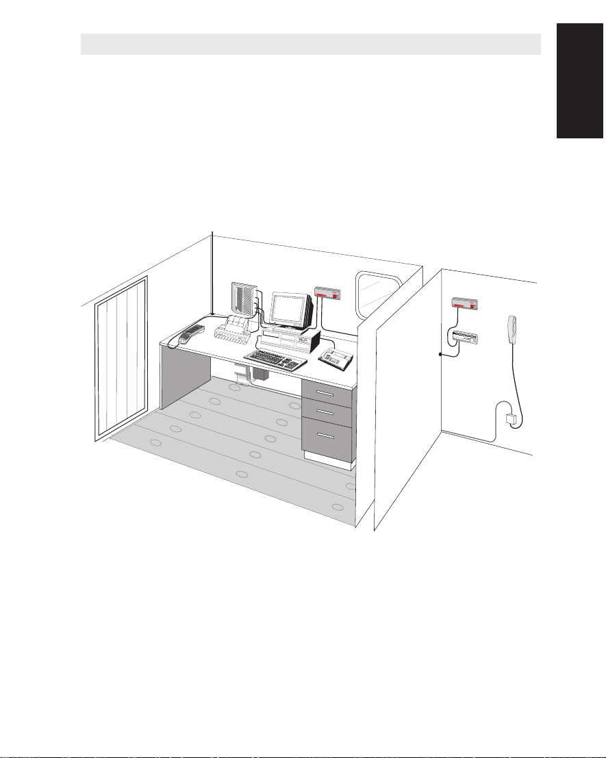
The figure below shows the basic parts of a Below Deck Equipment
installation.
Introduction
Main Control
Unit
RF-Cable (to Antenna)
Display
Handset
Printer
Termination
Box
Figure 1.1 Example of
BDE installation.
PC
(Telex)
Power
Supply
Distress
Alarm
N
e
r
a
S
a
tu
r
n
B
DISTRESS
A
L
A
R
M
A
C
K
N
O
W
LE
D
G
E
Telefax
Distress
Alarm
Nera Saturn B
DISTRESS
A
L
A
R
M
A
C
K
N
O
W
L
E
D
G
E
Telephone
Message
Indicator
Message Indicator
Saturn B
F
A
X
M
E
S
S
A
G
E
T
D
E
A
L
T
E
A
X
M
M
E
E
S
S
S
S
A
A
G
G
E
E
R
E
S
E
T
Remote installations
Saturn B – Chapter 1. Getting Started 1.1
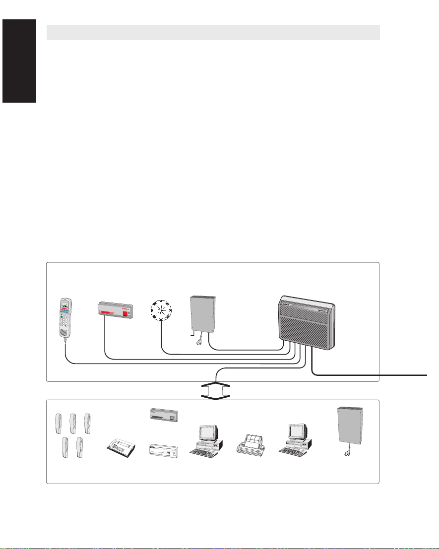
Introduction Cont’d
Below Deck Equipment - BDE
Main Control Unit
The Saturn Bm Main Control Unit (MCU) - which constitutes the
Introduction Cont’d
Standard Connection
major electronic part - is designed for wall or desktop installation. The
MCU power requirement is 150 W at 11 - 34 VDC.
Display Handset
The Display Handset keypad and built-in display allows dialing and
alphanumeric editing for communication and system control.
Distress Alarm
The Distress Alarm provides activation and indication of an alert
transmission.
Power Supply
220 VAC to 28 VDC with battery backup of MCU (including ACU and
RF units).
Display
handset Main Control Unit MCU
DIAL 00+INTL
TEL.NO.+
SHIFT
ON
DEL
1
2
3
4
5
6
7
8
9
0
Distress Alarm Unit
N
e
ra
S
a
tu
rn
B
DISTRESS
A
LA
R
M
A
C
K
N
O
W
L
ED
G
E
Gyro
interface
Power Supply
24 VDC
Additional Connection to MCU
DISTRESS
Saturn B
A
L
A
R
M
A
C
K
N
O
W
L
E
D
G
E
Extra
Distress Alarm(s)
(max6)
Message Indicator
SATURN B
FAX
M
ESS
AGE
DATA M
ESSA
G
T
E
E
LE
X MESS
AG
E
RE
SET
Telephones
(wall or desk)
Telefax
(replacing a
telephone)
Message
Indicator(s)
(max 4)
PC (Telex) Printer (serial)
PC (Data)
Saturn B – Chapter 1. Getting Started1.2
Power Supply
with stabilized DC for
Printer and PC
Introduction Cont’d
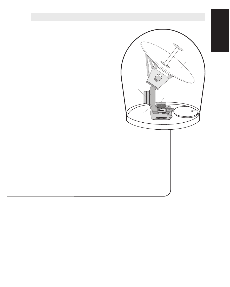
Above Deck Equipment - ADE
The Saturn Bm Above Deck
Equipment consists of:
• Stabilized Antenna with
RF Units and
Antenna Control Unit,
ACU
• Radome
The stabilized antenna is
mounted on the Azimuth
Post.
The ADE should be separated
as far as possible from the HF
antenna, and preferably by at
least 5 m from the antennas of
other communication or
navigation equipment.
RF-Unit
Servo
Stabilized
Pedestal
Radome
Antenna
Control
Unit
Antenna
Dish
Access
Hatch
Introduction Cont’d
Optional Equipment
•
DTMF telephones (max 5)
• Telefax (for connection to a telephone port)
• Message Indicator, activated on reception of telex, telefax or data
traffic.
• PC (Telex)
• PC (Data)
• Serial printer
Saturn B – Chapter 1. Getting Started 1.3

Introduction Cont’d
Enhanced Functions
The following Enhanced Functions are available as standard for
Saturn B:
Introduction Cont’d
• Charge tone, which sends a tone on selected telephone ports
when charging starts.
• Traffic log, which logs traffic data from selected telephone ports
and provides detailed printout.
• Access code, which assigns a personal 1-8 digit code to up to
100 authorized users. The code opens the system for one call.
The Enhanced Functions below are available as options for
Saturn B:
• Precharge, which allows preprogramming the Saturn B terminal
with a maximum total call duration. The maximum call duration can
be extended by the owner.
• Restricted LES, which allows the owner to lock the terminal to
one specific LES per Ocean Region.
• Restricted Dialing, which allows calls to preprogrammed short
numbers only.
• STU III and STU IIB, functions which prepare selected port(s) for
use with analogue encrypted telephone(s).
• Credit Card Phone, which prepares selected port(s) for use with
credit card telephone.
Activation of the optional functions requires individual opening keys
provided when purchasing the functions.
Refer to the "Saturn B/M Enhanced Functions, Operator’s Manual".
Telex Option
Two versions of Saturn B Telex Terminal software are available for
telex messaging:
• Normal version
• GMDSS version
The normal version can be run on a conventional PC w/printer.
The GMDSS version can only be run on a dedicated PC delivered by
NERA.
Refer to the "Saturn B Telex, Operator’s Manual".
Saturn B – Chapter 1. Getting Started1.4

Introduction Cont’d
Saturn B Data Service
The Asynchronous Data Service (ASD) offers data transmission at
9.6 kbps via the built-in modem feature of the Saturn B terminal.
Only modem communication software needs to be installed in the
associated PC to allow data transfer.
The Asynchronous Data Service is provided as standard feature.
The optional High Speed Data Service (HSD) service offers a
synchronous 56/64 kbps full duplex link with a terrestrial ISDN network:
• High speed data transfer, connection to data networks
• Video transfer, compressed store-and-forward transmission
• Video phone with hotline facility
• Multichannel audio transmission
• Multiplexed data, facsimile and voice.
With the optional Datacom Switch Unit (DSU) it is possible to have
HSD and ASD equipment connected at the same time.
Saturn Bm Dual Antenna
On some Saturn B installations the antenna cannot be mounted in a
non-obstructed area.
The Dual Antenna system remedies this by using two complete
Saturn-B installations with antennas located in positions obtaining a
combined unobstructed view. The Saturn Bm Dual Antennas are
normally fitted with Rotary Joint to provide no-rewind azimuth rotation.
The Dual Antenna function requires software version 7.12 or above.
Lease Mode operation is a mandatory requirement.
Introduction Cont’d
Saturn B Lease Mode
Inmarsat offers a Lease Mode of operation for parties that want to
establish closed networks.
A Saturn B terminal may be equipped with Main Control Unit software
designed for operation with leased satellite channel capacity.
Lease Mode operation must be agreed upon with the responsible Net
Service Provider.
The terminal must be commissioned to a Lease Gateway LES given
Saturn B – Chapter 1. Getting Started 1.5

Introduction Cont’d
by the Net Service Provider.
The software also allows the user to operate the Saturn B terminal in
normal mode with all available functions and services, except dis-
Introduction Cont’d
tress.
Saturn B External Modem Option
The Saturn B External Modem Option makes it possible to set up a
dedicated carrier over Inmarsat Lease satellites. This is obtained
through an Inmarsat Lease Gateway from a Saturn B mobile terminal
equipped with an external Interface Converter Unit (ICU), a Comtech
Modem and software release 7.xx series.
When installed, the ICU allows the Saturn B to operate as an ordinary
Inmarsat terminal as well as on a leased channel . The user's DTE
equipment is connected to the Comtech Modem. Data traffic bypasses the Saturn B Main Control Unit completely. The Saturn B
terminal, however, controls the Antenna pointing and the High Power
Amplifier (HPA). Saturn B External Modem operation is based on the
following services:
• Saturn B Lease Mode, a service offered by Inmarsat for parties
that require closed network operation.
• Nera EBM, Enhanced Bandwidth Module
• Nera VBS, Variable Bandwidth Service
The above service options are enhanced functions that must be
bought, installed and activated in the Saturn B MCU (function no. 89,
Enhanced Setup) to enable external modem operations in various
configurations.
Saturn Bm Mk2 Antenna with Rotary Joint
A Rotary Joint modification kit can be delivered to Saturn Bm Mk2
to provide unlimited azimuth rotation.
The standard Saturn Bm Mk2 Antenna has a limited azimuth rotation
(± 270 degrees from the bow) and will cause loss of satellite synchronization due to antenna rewind.
The Rotary Joint sustains uninterrupted satellite synchronization.
Furthermore, when interrupted by an obstruction the Antenna will
maintain the direction towards the satellite.
Saturn B – Chapter 1. Getting Started1.6
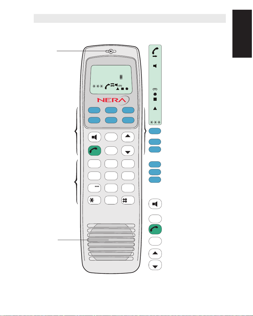
Handset w/Display & Keypads
The figure below shows all keys and indicators required for full operation and
control of Saturn B.
Handsfree
microphone
2 x 12 character
alphanumerical
LCD display.
Auxiliary keys:
Allows entering of
short numbers,
changing Ocean
Region, selecting
Land Earth Station
etc.
Number keys:
Only the number keys
are required to call
the end subscriber.
Pressing ALPHA
selects letter entries.
Pressing SHIFT
selects secondary
functions.
DIAL 00+INTL
TEL.NO.+
SHIFT BAT
ALPHA
ON
FUNC ALPHA ENTER
MORE/
SHIFT
13
456
789
HELP
ON/OFF
DEL
ESC
2
ABC
JKL MNO PQR
STU VWX
DATA
0
PLAY
DEF
TAX LIGHT
ÄÖÜ
LES
PTT
LIST
LIST
GHI
YZÆ
SPCØÅ.
Displayed when applicable:
at hook OFF
when additional info/help is
available.
when loudspeaker is ON.
SHIFT
when pressing SHIFT to use
secondary functions.
when pressing ALPHA to select
keypad letters.
during data calls.
when in contact with LES or NCS.
when receiving a call. Lights
steadily during communication.
flashes when receiving important
information/alarms.
when power is turned ON.
ON
1 - 3 signal quality indicators.
FUNC
Selects functions and displays HELP
page if any.
ALPHA
Selects alphabetic key function
ENTER
Moves to next choice, or enters
selected one. Access to Active Alarms
list (SHIFT function).
SHIFT
Selects secondary functions.
MORE/
Displays additional information/help.
HELP
LES
Direct access to Default LES
PTT
selection, and Ocean Region
selection (SHIFT function).
Push-To-Talk (PTT) when loudspeaker is operative.
Turns internal loudspeaker ON/OFF.
Switches between handsfree w/PTT
and normal use.
ON/OFF
Not in use
& Keypad
Handset w/Display
Toggles hook switch, or reverts to
ESC
Handsfree
loudspeaker
Figure 1.2 Keys and indicators
on Display Handset.
previous position
DEL
Deletes last character entry, or
complete entry.
Steps down/up through function
LIST
menu/choices.
LIST scrolls through choices
LIST
(SHIFT function).
Note!
The terms Mobile Earth Station (MES) and
Land Earth Station (LES) are sometimes
referred to as Ship Earth Station (SES) and
Coast Earth Station (CES) respectively.
Saturn B – Chapter 1. Getting Started 1.7
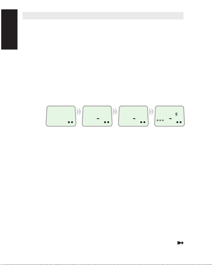
Starting Up
Switching ON
Starting Up
The POWER Switch on the back panel of the Main Control Unit
switches all basic units of the Saturn Bm terminal on/off:
• the Display Handset
• the Main Control Unit (MCU), and the Antenna Unit
See figure 1.3 for location of the POWER switch and POWER indicator.
For optional equipment, see their Operating Manuals.
The Saturn Bm should normally be switched ON at all times.
Switching ON initiates a self-test and an automatic satellite search
(which may take a few minutes), causing the following messages to
be displayed:
When
switching on:
During initialization
and self-test: When ready:
PLEASE WAITONSYSTEM
INITIALIZING
ON
During antenna
auto search:
SEARCHING
SATELLITE
ON
DIAL 00+INTL
TEL.NO.+
ON
The self-test should be ready within approximately one minute. If not,
see list of "Startup messages" in Appendix D.
The Saturn Bm retains the gyro, azimuth and elevation data when the
terminal is switched OFF. When switching ON, the antenna is automatically pointed in the same direction it had before switching OFF.
When switching ON Saturn Bm for the first time, the following must
be entered/selected:
• Ship’s heading, see next page.
• Ocean Region, see next page.
• Default Distress LES,
see "Selecting Default Distress LES" in chapter 3. Configuration.
• Distress Alarm address,
see "Configuring Ports" in chapter 3. Configuration.
• Search for satellite must be initiated, see next page
Saturn B – Chapter 1. Getting Started1.8
Starting Up Cont’d
Note! Entering gyro data and initiating a satellite search require that
the Saturn Bm User Level is extended to "Operator Level", see "Set-
ting User Level" in chapter 2. Operation.
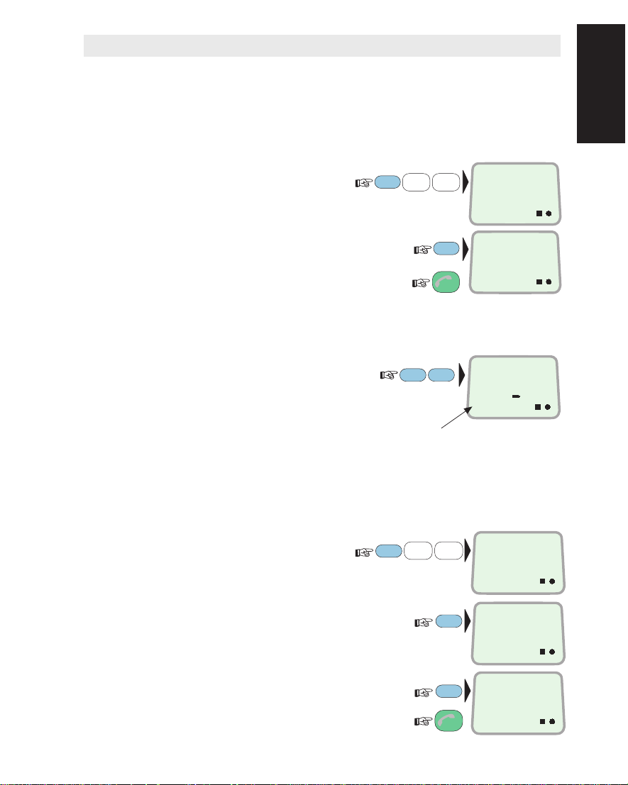
Checking Heading Data
Check the current heading input:
Select READ/SET
•
function (29):
Check setting:
•
and revert to IDLE:
•
To update gyro input, see "Heading
Input" in chapter 2. Operation.
Ocean Region
Check current selection:
and revert to IDLE:
To select another region, see
"Selecting Ocean Region"
in chapter 2. Operation.
Initiate Satellite Searching
Start a hemispheric scan for the selected satellite/Ocean Region:
Select SEARCH FOR
•
SATELLITE function (26):
PLAY
2
SHIFT
2
LIGHT
9
DEF
YZÆ
ENTER
ESC
LES
PTT
PLAY
6
DEF
PQR
FUNC
3x
Ocean Region ref. no.
FUNC
READ/SET
COMPASS
29
ON
HEADING:
275 DEG
ON
OCEAN REGION
IOR
3
ON
SEARCH FOR
SATELLITE
26
ON
Starting Up Cont’d
Press ENTER as prompted to
•
activate the search function:
Press ENTER again to actually
•
start the satellite search:
and revert to IDLE:
•
2x
PRESS ENTER
ENTER
TO SEARCH
COMMAND
ENTER
ACCEPTED
ESC
ON
ON
Note! The search may take a few minutes.
Saturn B – Chapter 1. Getting Started 1.9
Starting Up Cont’d
Signal Quality Indication
The signal quality indicators are
displayed during communication
Starting Up Cont’d
Observing Signal Strength
and signal strength readout:
1 - 3 asterisks – increasing
quality of communication.
No asterisks – call may be
possible, but uncertain.
Pressing SHIFT + 7 displays
the signal strength:
Signal quality
indication
SHIFT
7
DIAL 00+INTL
TEL.NO.+
STU
S/N: 254
ON
ON
Pressing MORE/HELP displays
the "BER" value:
The lower the value the
better the signal quality.
Revert to IDLE:
Not used in
Saturn Mm/Bm
MORE/
HELP
ESC
BER : 48
SOUND OFF
ON
Note!
The signal strength reading (S/N=Signal/Noise ratio) will vary during a
call.
The Bit Error Rate (BER) reading decreases as the quality of the
received signal improves.
Saturn B – Chapter 1. Getting Started1.10
Call through Default LES
Ready for operation:
•
To check the default LES
in this Ocean Region:
(
To modify, see "Selecting Default LES"
in chapter 2. Operation.)
Call from Display Handset
DIAL 00+INTL
TEL.NO.+
ON
IOR
LES
PTT
LES 4
3
ESC
ON
Handset
Call from Display
1 Key in the international
call prefix 00:
2 Key in the country code,
e.g. 47 (Norway):
(
See appendix B for list of
telephone country codes)
3 Key in subscriber
number:
(within 45 seconds)
4 Initiate the call:
Slow beeps are heard during call setup.
The square indicator appears when LES
has accepted the call.
Ringing tone is heard until answer.
5 Clear the call when finished:
For short number and last number
dialing and other functions,
see chapter 2. Operation.
Call through Selected LES
6 Enter the LES code:
Continue from step 1.
(See appendix A for Satellite Coverage Map
and list of Land Earth Stations.)
0
0
ÄÖÜ
7
4
JKL
PLAY
2
7
6
PQR
STU
4
JKL
4
DEF
JKL
7
STU
0
0
ÄÖÜ
3
GHI
LES 004
ÄÖÜ
00
LES 004
STU
0047
LES 004
ÄÖÜ
004767244700
SPC
DIAL 00+INTL
ESC
TEL.NO.+
DATA
LES 003
ØÅ.
ON
ON
ON
ON
ON
Saturn B – Chapter 1. Getting Started 1.11

Call from Telephone
General
A telephone is used for basic telephone calls. Control of functions
and other facilities must be done from the Display Handset.
Call from Telephone
Call through Default LES
0
0
7
4
4
2
7
6
7
4
0
0
routes the call via
the default Land Earth Station for the Ocean Region you are operating in.
Call through Selected LES
0
0
4
7
6
7
2
4
4
7
0
4
0
call via the Land Earth Station Eik (4) in Norway.
Last Number Redialing
0
retransmits the last number*.
Last Number Redialing through Selected LES
4
(Eik=4)
0
*
.
retransmits the last number via the selected LES
Short Number Dialing (Prefix 23)
2 3 1 5
under short number 15
fetches and sends the telephone number stored
*.
Short Number Dialing (Prefix 23) through Selected LES
2
3
4
1
stored under short number 15 via the selected LES (Eik=4)
fetches and sends the telephone number
5
routes the
*.
*Also applies when dialing from Display Handset.
Saturn B – Chapter 1. Getting Started1.12

General
Service Address Calls
The LESs support special information services accessible with 2-digit
Service Address Codes. See appendix B.
Example of obtaining assistance from the International Operator
where the default LES is situated:
Service Address Calls
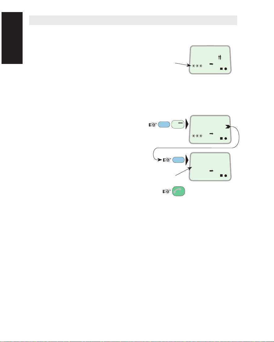
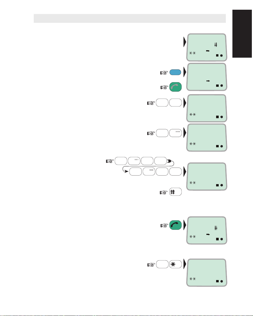
Lift handset and dial:
Example of obtaining meterological information from a selected LES,
e.g. Eik:
Lift handset and dial:
Note! Not all LESs provide every service listed. For more information
contact technical assistance on 33 #.
1
1
4
4
1
Saturn B – Chapter 1. Getting Started 1.13
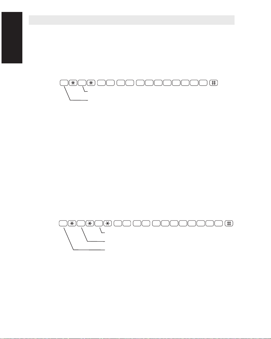
Terrestrial Network and Priority Calls
Terrestrial Network
Dialing through terrestrial network is only possible using selected
LES.
and Priority Calls
Terrestrial Network
Priority Calls
The number may be in the range of 0 to 127.
Example of call through selected LES, e.g. Eik, and network 1:
0 0 4 7 6 7 2 4 4 7 0 014
PSDN NETWORK PROVIDER
NET SERVICE PROVIDER
The following call priority levels are recognized by the Inmarsat
system:
0 – Routine
1 – Safety
2 – Urgent
Saturn B normally transmits calls with priority 0: Routine.
Whether you are using the Display Handset or a telephone, dialing
or
2 ahead of the ordinary call digits gives the call priority 1 or 2
*
respectively.
Assignment of priority level is only possible using selected LES and
selected network.
Example of priority 1 call through e.g. Eik:
0 0 4 7 6 7 2 4 4 7 0 0114
PRIORITY
PSDN NETWORK PROVIDER
NET SERVICE PROVIDER (LES CODE)
Saturn B – Chapter 1. Getting Started1.14
2
*

General
Limitations
Using Telefax
Fax calls placed through the Saturn B are telefax only. Any telephone
handset connected to the telefax machine is for dialing purposes
only.
To send a fax, use the same dialing sequence as when using a
telephone, either through the default LES, or a selected one:
see "Call from Telephone".
Telefax transmissions normally take 1.5 minute per standard text
page using standard resolution. Using superfine or halftone resolution
will double the transmission time. Avoid using a separate cover page.
The transmission rate is 9.6 kbps.
If a call failure should occur while sending a multi-page document, resend only the failed pages.
Saturn B is fully compatible with the world’s leading telefax machines
and telefax software standards. However, transmission may not be
possible through some of the telefax machines available on the
market. Please check with your agent before purchasing a telefax for
use with the Saturn B.
Using Telefax
Saturn B – Chapter 1. Getting Started 1.15
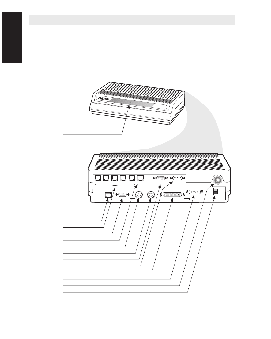
Connector Panel
The figure below shows the location of the power ON/OFF switch
and power indicator, as well as all connectors accessible on the rear
panel of the Main Control Unit (MCU).
For connections, refer to the Saturn Bm Installation Manual.
Connector Panel
Power indicator
TEL.1 TEL.2 TEL.3 TEL.4 TEL.5
AUX
HANDSET
EXT I/O GYRO
5 4 3 2 1
9 8 7 6
NMEA-0183
Saturn B
5 4 3 2 1
9 8 7 6
PC PRINTER
1 2 3 4 5
6 7 8 9
DTE
13 12 11 10 9 8 7 6 5 4 3 2 1
25 24 23 22 21 20 19 18 17 16 15 14
+ [11 - 34 VDC] -
OFF
ON
Auxiliary
Telephone/telefax
Extensions
Telephone display handset
Gyro
Navigator NMEA-183
PC (control/telex)
Printer
PC (data)
Power
Antenna connector
Power ON/OFF
Figure 1.3 MCU connector panel.
Saturn B – Chapter 1. Getting Started1.16

Contents
Using the Display Handset ..........................................................2.1
Functions .....................................................................................2.5
Selecting Ocean Region..............................................................2.8
Short Numbers ............................................................................2.9
Last Number Redialing..............................................................2.12
Active Alarms.............................................................................2.13
Info Log .....................................................................................2.14
Clear Cause Log * .....................................................................2.15
Terminal Status *.......................................................................2.16
Setting User Level .....................................................................2.17
Selecting Default LES ...............................................................2.18
System Information * .................................................................2.19
Group Calls * ............................................................................. 2.20
Geographic Position *................................................................2.21
Satellite Search * .......................................................................2.22
Heading Input *..........................................................................2.26
Antenna Azimuth Limit...............................................................2.27
Manual Antenna Pointing * ........................................................2.28
Message Indicator .....................................................................2.30
Distress Alarm ........................................................................... 2.31
Chapter 2. Operation
OPERATION
* Functions marked with a star are only accessible when
Saturn Bm is set in OPERATOR LEVEL.
See "Setting User Level".
Nera SatCom AS reserves the right to change the design
and specifications of the equipment without notice.
Saturn Bm – Operator’s Manual

Chapter 2. Operation
Idle Mode
The following message
appears in the display
when in IDLE mode:
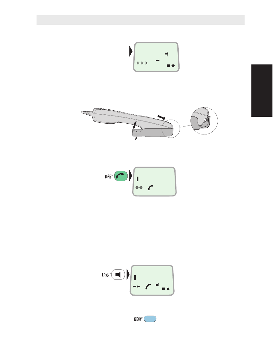
Hook ON/OFF
The Display Handset is secured in a desk- or wall-mounted bracket:
A magnet toggles the internal hook switch. The switch can also be
toggled with the combined HOOK ON/OFF and ESCAPE key:
Using the Display Handset
DIAL 00+INTL
TEL.NO.+
click!
Hook ON/OFF magnet
DIAL NO.
ESC
ON
Using the Display Handset
Beeps in the Handset
Before contact is established with the selected LES beeps indicate
attempts.
Loudspeaker
When off-hook the loudspeaker key toggles the Display Handset
loudspeaker ON and OFF:
DIAL NO.
ON
When the loudspeaker is ON, the handset microphone is OFF and
the Push-To-Talk key must be kept pressed while talking and released while listening:
Saturn Bm – Chapter 2. Operation 2.1
LES
PTT
Using the Display Handset Cont’d
Volume Control
The received volume in the Display Handset may be adjusted during a call:
• Reducing the volume:
LIST
• Increasing the volume:
The volume is reset when clearing the call.
Light in Display and Keys
Using the
Illumination of the display and keys is turned on and off as follows:
Display Handset
Indicators on the Display Handset
flashes when receiving important information or an alarm.
The indicator stops flashing once an alarm has been read:
press SHIFT+ENTER, or see "Active Alarms".
flashes when receiving a call to Saturn B Display Handset.
The indicator stops flashing when the call is established and
remains displayed until the call is cleared.
displayed steadily as long as Saturn B remains synchronized
with the Land Earth Station (LES), or Network Coordinating
Station (NCS). The indicator flashes slowly when no one is
talking from the remote end during a call.
SHIFT or ALPHA
The functions marked red on the keypad may only be activated when
the SHIFT indicator is displayed.
The keypad letters may only be activated when the ALPHA indicator
is displayed.
LIST
LIGHT
SHIFT
9
YZÆ
DIAL 00+INTL
TEL.NO.+
SHIFT
ALPHA
ON
SHIFT
ALPHA
SHIFT and/or ALPHA are automatically deactivated when reverting to
IDLE mode.
Saturn Bm – Chapter 2. Operation2.2
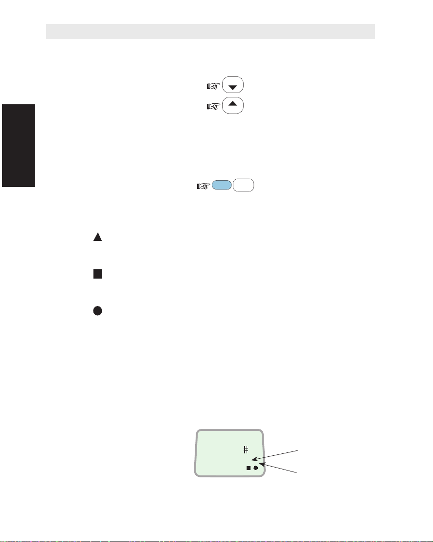
Moving about in the Display
To scroll up/down through
functions or choices:
To move to next choice
or enter the selected one:
To move back to previous
position or display:
Note! Entered changes
are lost when pressing ESCAPE.
Keying Letters
The letters on the keys are accessible when having pressed the
ALPHA key. Each key carries several letters that are entered successively as follows:
• Set keypad in
alphanumeric state:
• Press and hold the
required key until the
wanted letter appears
in the display:
Using the Display Handset Cont’d
LIST
ENTER
ALPHA
1
1
LIST
ESC
ABC
ABC
Using the
Display Handset
1
ABC
Deleting an Entry
To delete entry (to the
left of the cursor):
DEL
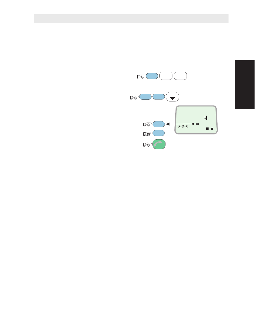
Service Dialing (During Call Only)
The Display Handset can be used for keying in the numbers for e.g.
bank services, voice letters etc., using tone signalling (DTMF).
Before keying in the numbers required by the service, press:
Note! Service dialing is
not supported by all LESs.
Saturn Bm – Chapter 2. Operation 2.3
SHIFT
0
ÄÖÜ

Using the Display Handset Cont’d
Call Duration
The duration of a call as it proceeds can be read in the display, as
well as the accumulated time of all calls.
Ongoing call duration:
(remains until next call)
Using the
Display Handset
Call Clearing Messages
Alarm Messages
Accumulated time:
(Reset with DEL key)
A clearing condition causes a brief message to be displayed along
with a reference number.
An alarm causes the triangle
indicator in the display to flash.
To read the alarm message:
Scroll through additional alarms, if any:
SHIFT
8
Hours:minutes:seconds
SHIFT
TAX
THIS CALL
VWX
0 : 12 : 33
TOTAL CALLS
MORE/
HELP
10 : 55 : 44
ENTER
LIST
LIST
ON
ON
ACU RAM
FAILURE
7
ON
Revert to IDLE:
3x
ESC
Table with comments is provided in appendix D.
Saturn Bm – Chapter 2. Operation2.4
Alarm indicator
General
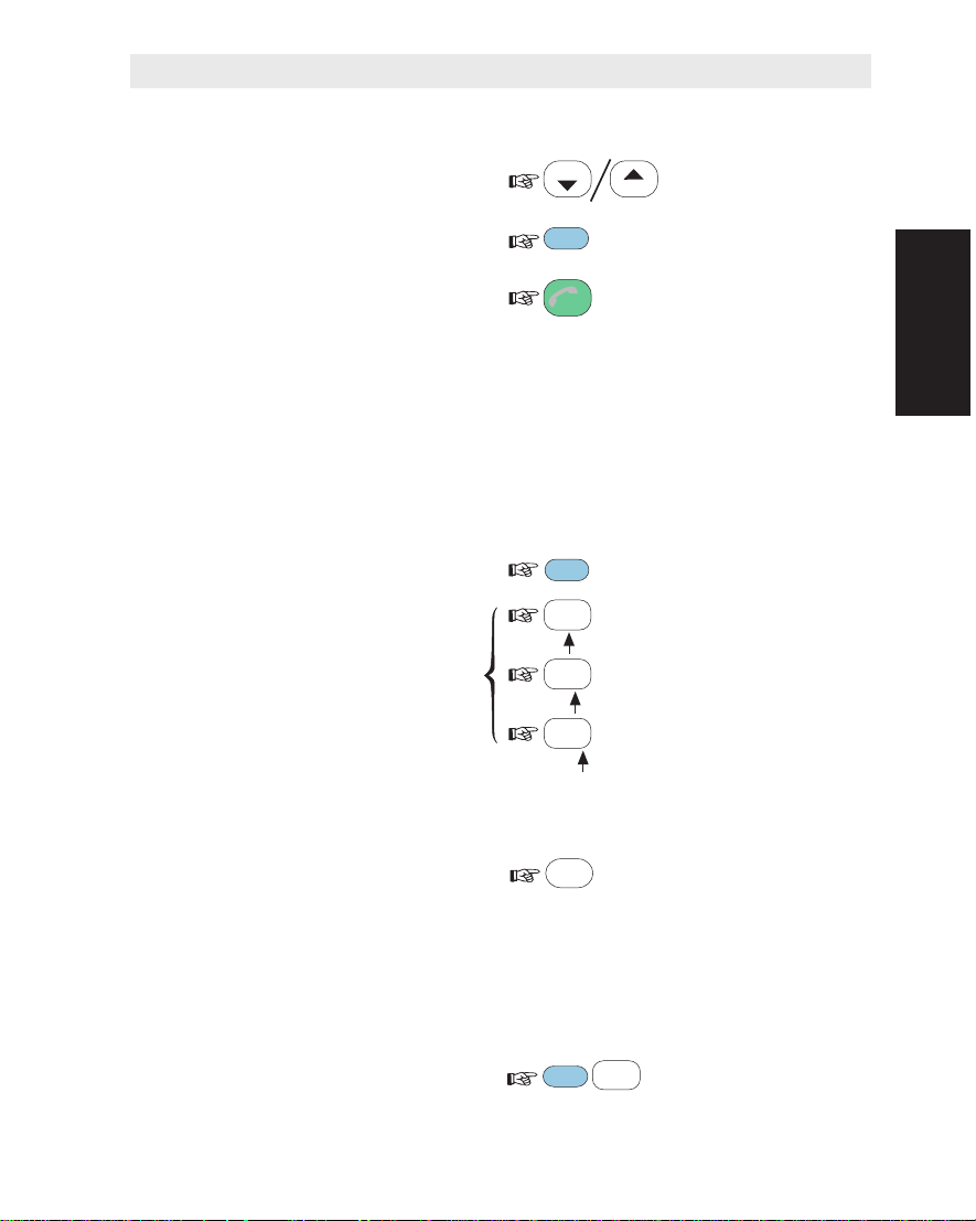
Functions
The many functions available are explained throughout this chapter.
See list of functions in table 2.1, and appendix E.
Each menu and function is assigned a specific number.
• A function may be selected directly
by its number, for example
LAST NUMBER LIST (11):
FUNC
1
1
ABC
ABC
• or by searching with
• For extended lines or help:
• For field description:
• To revert:
User Levels
The functions are accessible from the following levels, designated:
• USER level, which includes basic functions such as short number
• OPERATOR level (marked with stars in table 2.1), which adds
• RENTER and OWNER levels (password protected):
Saturn B is automatically set to USER level when turning on power.
For selection of OPERATOR level, see "Setting User Level" in this
chapter.
the ARROW keys:
FUNC
LIST
ENTER
DIAL 00+INTL
MORE/
HELP
FUNC
ESC
dialing, selecting Ocean Region etc.
more advanced functions such as date & time setting, configuring
ports etc.
see Operator’s Manual for "Enhanced Functions".
TEL.NO.+
ON
Functions
Saturn Bm – Chapter 2. Operation 2.5

Functions Cont’d
Functions Cont'd
1 – NUMBER LISTS AND USER LEVEL
10 SHORT NUMBER LIST
11 LAST NUMBER LIST
12 SET USER LEVEL
13 SET PASSWORD
*
14 GROUP ID NUMBERS
*
2 – REGION AND ANTENNA CTRL
20 CURRENT OCEAN REGION
21 GEOGRAPHIC POSITION
*
22 NAV AREA
*
23 IMO SAR AREA
*
24 WMO AREA
*
25 ICAO SAR AREA
*
26 SEARCH FOR SATELLITE
*
27 ANT. ABS. POINTING
*
28 ANT. REL. POINTING
*
29 READ/SET COMPASS
*
3 – ALARMS AND MESSAGES
30 ACTIVE ALARMS
31 INFO LOG
32 CLEAR CAUSE LOG
*
33 TERMINAL STATUS
*
4 – SYSTEM INFORMATION
40 MES ID
*
41 MCU PROGRAM VERSION
*
42 ACU TYPE / ACU/PCU VER.
*
43 DSP PROM VERSION
*
44 BOOT PROM / HANDSET VER.
*
5 – TERMINAL CONFIGURATION
50 DEFAULT LES
*
51 CONTRAST ADJUST
*
52 RING VOLUME ADJUST
*
53 DATE AND TIME
*
54 STAND-ALONE LES
*
55 DISTRESS LES
*
56 DISTRESS TEST
*
6 – BULLETIN BOARD DATA
60 LES CAPABILITIES
*
7 – INSTALLATION COMMANDS
70 CONFIGURE PORTS
*
71 INCOMING CALL ROUTE
*
72 COMMISSION STATUS
*
73 ANTENNA CONFIG.
*
74 COMPASS TYPE
*
77 VARIOUS CONFIG
*
8 – ENHANCED FUNCTIONS
89 ENHANCED SETUP
*
The "Enhanced Functions" available depend
on the configuration of your Saturn Bm terminal.
See description of "Enhanced Functions".
OPERATOR LEVEL
*
Table 2.1 List of menus and functions. See also appendix E.
Saturn Bm – Chapter 2. Operation2.6
 Loading...