

Nera Inmarsat-c Service Manual
Nera C
Service Manual
INMARSA T -C MOBILE EARTH STA TION


s
Content
Check List
......................................................................................................................1
Chapter 1. General
1.1 General...........................................................................................................................1-1
1.2 Configuration ...............................................................................................................1-2
1.3 Connection ...................................................................................................................1-3
1.3.1 Antenna and terminal unit ..............................................................................1-3
1.3.2 [Junction] port ................................................................................................1-3
1.3.3 [LAN] port......................................................................................................1-5
1.3.4 [DTE] port ......................................................................................................1-5
1.3.5 [D-GPS] port ..................................................................................................1-5
Chapter 2. Block Description
2.1 Configuration.................................................................................................................2-1
2.1.1 Nera C.............................................................................................................2-1
2.1.2 Boards in each unit .........................................................................................2-2
2.2 Antenna unit, IC-115 .....................................................................................................2-4
2.2.1 ANT RF board (16P0207)..............................................................................2-4
2.2.2 Antenna element.............................................................................................2-5
2.3 Terminal unit, IC-215 ....................................................................................................2-6
2.3.1 RF CON/CPU board (16P0208A)..................................................................2-7
2.3.2 TERM CPU board (16P0209) ........................................................................2-19
2.3.3 Memory contents............................................................................................2-26
2.3.4 PWR board (16P0211)....................................................................................2-29
Chapter 3. Location of Parts
3.1 Terminal unit, IC-215 ....................................................................................................3-1
3.2 Antenna unit, IC-115 .....................................................................................................3-8
3.3 Distress alert received unit, IC-305 and ALARM unit, IC-306.....................................3-10
3.4 Junction Box, IC-315 (Option)......................................................................................3-12
Rev Date: September 2004
i
Publication No.: 105420 (Rev. 1.0)

Contents
Chapter 4. Set up
4.1 System menu (F8)..........................................................................................................4-1
4.1.1 Setting by DTE port........................................................................................4-1
4.1.2 System menu (F8)...........................................................................................4-2
1. Distress Alert Setup: [F8]-1.........................................................................4-2
2. System Setup: [F8]-2...................................................................................4-2
3. Editor Setup (Close the TEXT editor display.) : [F8]-3 ..............................4-4
4. Terminal Setup: [F8]-4 ................................................................................4-5
5. EGC Setup: [F8]-5.......................................................................................4-5
6. Auto Mode Setup: [F8]-6 ............................................................................4-5
7. Email Setup: [F8]-7.....................................................................................4-6
8. Directories: [F8]-8.......................................................................................4-6
9. Configuration: [F8]-9 ..................................................................................4-7
4.2 Setting from Command Window...................................................................................4-8
4.2.1 Remote Box Setup ..........................................................................................4-8
4.2.2 Setting of Internal GPS transmitting cycle......................................................4-9
4.3 Jumper setting of IC-305 and 306 .................................................................................4-11
4.4 PR-240 power alteration................................................................................................4-12
Chapter 5. Maintenance
5.1 PV (Performance Verification) test................................................................................5-1
5.1.1 PV test sequence.............................................................................................5-1
5.1.2 Procedure ........................................................................................................5-2
5.2 Self test..........................................................................................................................5-5
5.2.1 Self test when the system is turned on............................................................5-5
5.2.2 Self test from function menu...........................................................................5-5
5.2.3 TROUBLE message........................................................................................5-6
5.3 Status monitor................................................................................................................5-8
5.3.1 Items on the status monitor.............................................................................5-8
5.3.2 NG analysis.....................................................................................................5-11
5.4 Checking BPSK waveform............................................................................................5-13
5.5 LED ...............................................................................................................................5-14
5.5.1 IC-215.............................................................................................................5-14
5.5.2 IC-305, 306.....................................................................................................5-16
5.6 DIP switch and Reset switch on IC-215........................................................................5-17
ii

5.7 Checking LES Information............................................................................................5-18
5.8 Changing Back-up battery on TERM CPU board.........................................................5-20
5.9 Clearing Memory...........................................................................................................5-21
5.10 Distress alert test..........................................................................................................5-22
5.11 Saving and loading of system setting...........................................................................5-24
Contents
Chapter 6. Updating program
6.1 Updating program..........................................................................................................6-1
6.1.1 Checking program version..............................................................................6-1
6.1.2 Procedure ........................................................................................................6-2
6.2 Program files..................................................................................................................6-3
6.3 Installing Terminal software to PC................................................................................6-3
Chapter 7. Messages
7.1 Status display.................................................................................................................7-1
7.1.1 Display of bottom left.....................................................................................7-1
7.1.2 Display of bottom center.................................................................................7-4
7.1.3 Display of bottom right...................................................................................7-5
7.1.4 Display of upper part.......................................................................................7-6
7.1.5 Display of status display part ..........................................................................7-7
7.2 Messages for Operation.................................................................................................7-8
7.2.1 Messages for [F1], File menu .........................................................................7-8
7.2.2 Messages for [F3], Transmit menu.................................................................7-8
7.2.3 Messages for [F5]-1, Data Report menu.........................................................7-9
7.2.4 Messages for [F7]-6-1, PV test.......................................................................7-9
7.2.5 Messages for Printer (Output from TERM CPU)...........................................7-9
7.3 Cautions and information message................................................................................7-10
iii

Contents
Appendix 1) Inmarsat system.................................................................AP1-1
AP1.1 System Overview..........................................................................................AP1-1
AP1.1.1 System Configuration ........................................................................AP1-1
AP1.1.2 Inmarsat C Services ...........................................................................AP1-3
AP1.1.3 Destination Type................................................................................AP1-4
AP1.1.4 Charging.............................................................................................AP1-6
AP1.1.5 Network .............................................................................................AP1-7
AP1.1.6 Frequency assignment........................................................................AP1-9
AP1.2 Message & Signal Transfer...........................................................................AP1-10
AP1.2.1 Ship- originated Call..........................................................................AP1-10
AP1.2.2 Shore- originated Call........................................................................AP1-12
AP1.2.3 Log in/Log out ...................................................................................AP1-15
AP1.2.4 Distress Alert .....................................................................................AP1-16
AP1.3 Channel types and Signal processing............................................................AP1-17
AP1.3.1 Channel types.....................................................................................AP1-17
1. NCS CC/LES TDM Channel...................................................................AP1-18
2. Signaling Channel....................................................................................AP1-19
3. MES Message Channel............................................................................AP1-21
AP1.3.2 Signal Processing...............................................................................AP1-22
1. Signal processing Flow for Each Channel...............................................AP1-22
Appendix 2) Menu Tree.............................................................................AP2-1
AP2.1 Menu Tree.....................................................................................................AP2-1
Appendix 3) Coast station service list.................................................AP3-1
AP3.1 Inmarsat C coast station service list .............................................................AP3-1
Appendix 4) E-mail.....................................................................................AP4-1
AP4.1 Features.........................................................................................................AP4-1
AP4.2 Limitations....................................................................................................AP4-2
AP4.3 Precautions....................................................................................................AP4-2
AP4.4 Network Setup menu ....................................................................................AP4-3
AP4.5 Setting LES...................................................................................................AP4-5
AP4.6 Setting Active Port........................................................................................AP4-7
AP4.7 Message Log.................................................................................................AP4-8
iv

AP4.8 Connection and setting..................................................................................AP4-9
AP4.8.1 Connection to single PC ....................................................................AP4-9
AP4.8.2 Connection of multiple PCs...............................................................AP4-11
AP4.8.3 Connection to multiple networks.......................................................AP4-12
AP4.9 Function settings...........................................................................................AP4-14
AP4.9.1 DHCP.................................................................................................AP4-14
AP4.9.2 SMTP Enable IP Address ..................................................................AP4-15
AP4.9.3 Mail Gateway.....................................................................................AP4-16
AP4.9.4 Selective forwarding..........................................................................AP4-18
AP4.9.5 Message size ......................................................................................AP4-20
AP4.9.6 Attachment conversion ......................................................................AP4-21
AP4.10 E-mail Client Setup (Outlook Express Ver.6).............................................AP4-22
AP4.11 Windows XP LAN setting ..........................................................................AP4-29
AP4.12 Connection check........................................................................................AP4-32
AP4.12.1 Checking by Ping command............................................................AP4-32
AP4.12.2 SMTP error message list..................................................................AP4-33
AP4.13 US ASCII code list......................................................................................AP4-34
Contents
Appendix 5) Specifications......................................................................AP5-1
Exploded View............................................................................................. D-1
Electrical Parts List....................................................................................E-1
Schematic Diagrams ................................................................................. S-1
v

Check List
Check List
- Check for waterproofing of the antenna.
- The receiving signal from selected satellite is not obstructed by other objects, such as a
crane. See AP1-2 for the satellite antenna direction.
1. Installation
The table 1 lists check items of the installation.
Table 1. Items to be checked of installat ion
No. Item to be checked Result Reference to
The current of the power supply cable, such
1 Power supply cable
2 Antenna cable
3 Other cable
Grounding
4
5 PR-240 specification
6 Connector The antenna connector is connected securely.
Indication
7
: IMN, AAB, CS, etc
as for the back up battery, is 5 to 7 A when
transmitting.
- The designated cable is used.
30m: TP5FBAW-5DFBB
50m: 8D-FB-CV
100m: 12D-SFA-CV
- The antenna cable is waterproofed.
Check for connection of the IC-305.
Check for connection of the IC-306.
IC-115: Antenna unit
IC-215: Terminal unit
PR-240: Power supply unit
- 220 VAC
- The power is supplied from both the main
source and the emergency source.
The indication is sealed around the terminal
unit.
4-12
2. Program version
See chapter 6.
The program version is checked by “Diagnostic Test” (keystroke: [F7]-7-3).
For the detail version, type “Nera” while pressing [Ctrl].
Table2. Program version
Program Detail version
TERM CPU 1650162-01.xx Ver
RF CON/CPU 1650159-01.xx V er
1

Check List
3. Settings
Table 3 lists check items for the setting.
Table 3. Items to be set
No. Items to be set Result Reference to
1 DMC-5
2 IC-305
3 IC-306
4 Distress Alert setup [F8]-1: Distress Alert setup 4-2
System setup
5
([F8]-2)
[F8]-2: Command Window
“Remote Box Setup”
[F8]-2: Command Window
“Remote Box Setup”
[F8]-2: Command Window
“Remote Box Setup”
IC-306 jumper setting 4-11
System Date & Time
Date: ZDA
Time: TDM frame data
IMN
Re-enter:
Type “IMN” while holding [Ctrl].
MES Operation Mode
INMARSAT C
EGC
NAV Port
OFF
INT: Internal GPS (Option)
EXT: External GPS
Active Port
INT
ALL
Message Output Port
INT
EXT
INT+EXT
AUTO
EGC Output Port
INT
INT+EXT
Network
- IP Address
- Subnet mask
- DHCP(ON/OFF)
- Gateway
Mail Gateway
- Attach
- Delivery To(PC Mailer/Server)
- Server IP
- Address Mode(FIXED/AUTO)
- Mail Address
- Auto Delivery keyword
(UUENCODE/BINARY)
4-8
4-8
4-8
4-2 to 4-4
2

Check List
4. Checking
Table 4 is the check list for items to be set.
Table 4. Check list for items to be set
No. Items to be checked Result
1 IC-306
2 IC-305 [F7]-7-4: Distress Alert Button Test 5-22
3 DMC-5
4 Error/Trouble message The message does not appear.
5 Diagnostics Test All Diagnostic Test ([F7]-7-3) is OK. 5-5
6 Status
7 FDD [F1]: Read/Write
Printer
8
(PP-510)
When [ALARM RESET] is pressed, the
buzzer and LED is an active.
[F7]-7-4: Distress Alert Button Test
** DMC setting should be set to “SES(EGC)
only. If it is set to VHF and MF/HF,
the distress alert is released from VHF and
MF/HF device. **
Position
Course/Speed (Displaying VTG data)
Current NCS
The receivable ocean region is set.
Antenna Power Supply 5-11
BBER: OK
C/N (The value is stable.)
31 to 34 dB and above: OK
Rx AGC Level: OK 5-11
REF Offset Freq.: OK 5-12
Synthe Local: OK 5-12
Send Level
Normally, “0” for receiving,
“255” for transmitting
Prints correctly.
- When turning on the unit while holding [LF]:
All character is printed.
- When turning on the unit while holding
[NLQ]:The printer setting value is printed.
5-22
5-11
Refere
nce to
5-6
Chapter7
5-8
4-3
2-15
5-8
5-11
5-13
5-11
3
Check List
5. Communication test
Before the test, check followings.
1) C/N of the status display is OK.
2) Its value is stable.
3) “Current Status” is “Idle”.
5.1 Log in
When Log in ([F7]-1) is succeeded, “Successful Login” appears.
If the trouble message appears, see the list below.
Table 5. TROUBLE message
TROUBLE message Description Remedy
ANT Power voltage
abnormality
1. Too many retries.
2. MES Signalling Failure,
Login Request not sent to
NCS.
3. Login failed.
4. Carrier power level
The supplied voltage error
for the antenna unit
1-3. Login failed
4. The transmit level is not
within the rating.
( actuality, no appears)
- Change IC-115 or PWR board.
- Check the antenna cable.
- Change IC-115 or RF CON/CPU.
- Check the antenna cable.
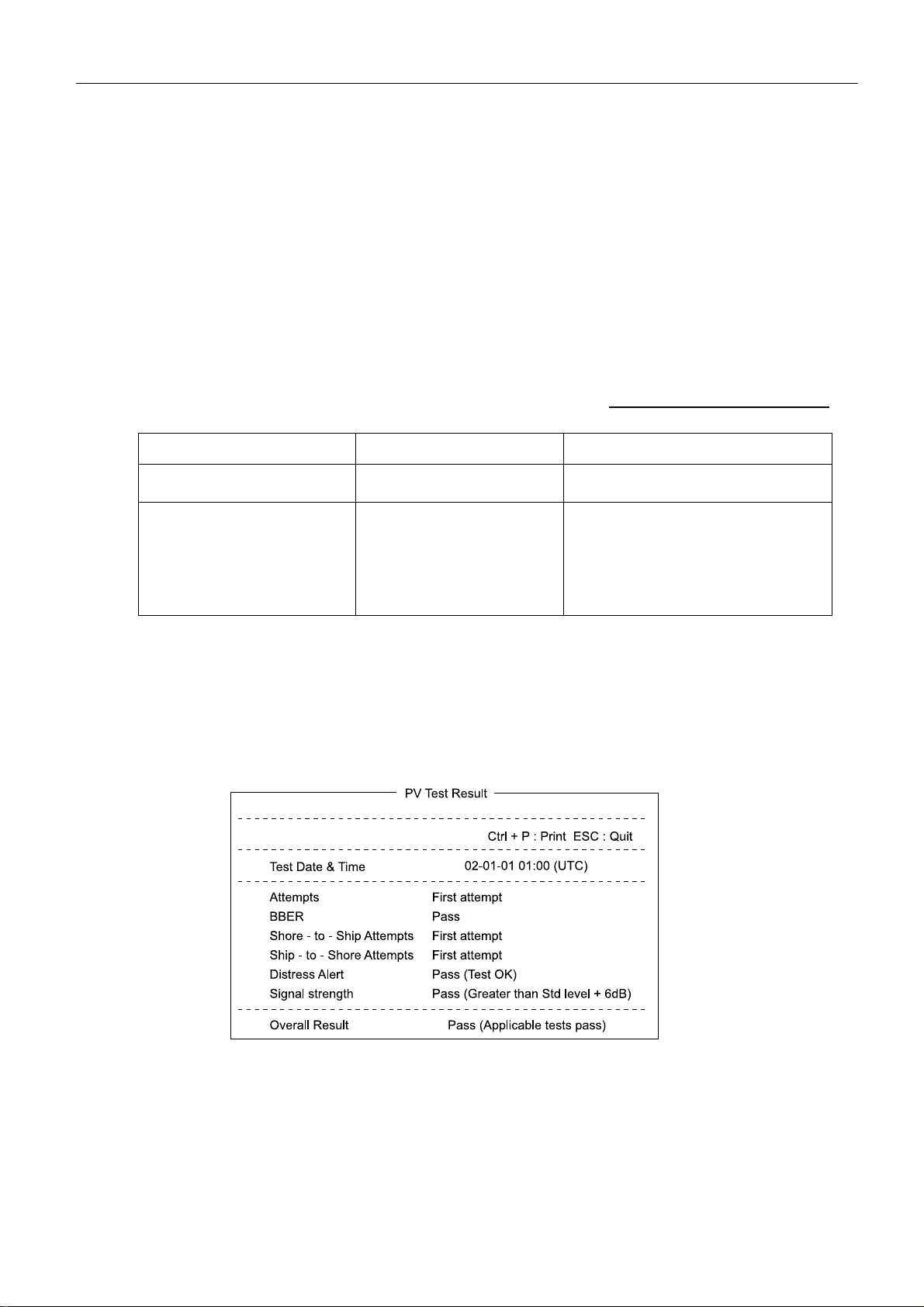
5.2 PV test
PV test is started by [F7]-7-1. OK When “Overall Result” is “Pass”. See page 5-1.
The PV test result ([F7]-7-2) should be printed out.
4

Check List
5.3 Loop back test
Start Loop back test which the message is send back to the own ship. The transmitting and
receiving message should be printed out.
1) Make a test message by “New” ([F1]-1).
2) Set following items by “Transmit Message” ([F3]-1).
- Priority : Normal
- Destination Type : TELEX
- Country/Ocean Code : The Ocean region to be selected
POR: 582, IOR: 583, AOR-W: 584, AOR-E: 581
- Station ID : To enter the own IMN
- LES ID : LES
- Option
Confirmation : ON
Send Delay : 00:00
Delivery Dela : Immediate
Code : IA5
3) Move the cursor onto “Transmit” and press [Enter].
4)
Select “YES” and press [Enter] to start the transmission.
5) When the same message is received after 5 to10 minutes, the test result is OK. If the
message cannot received correctly, confirm “Delivery” in “Send Message Log”
([F6]-1). See page 7.
5.4 EGC receiving
The alarm is checked by following the message priority.
The alarm is sounded from IC-305 and the Terminal unit by DIS/URG Message.
See page 2-17. The EGC receiving message should be printed out. See page 4-6.
5

Check List
6. Delivering
Before delivering, the following instruction is needed.
1) How to release the distress alert, use distress communication, cancel the false distress alert*
and stop the alarm.
2) How to register the “station list”.
3) How to “log in/log out”.
4) How to communicate by using “E-Mail and FAX”.
5) How to confirm the “delivery status”.
6) How to save and load the system setting value, such as the station list. See page 5-24.
7) Necessary items to be reported for inquiry when the trouble occurs.
- Error in detail, frequency, symptom
- Condition after changing the Ocean region and LES
- Following condition in status monitor;
current NCS, own ship position, C/N, BBER, Rx AGC Level, REF Offset Freq,
Synthe Local, Antenna Power Supply,
- Error message, Information message
*: Canceling the distress alert
To cancel the distress alert, report by the priority message (Priority: Distress ) to proper RCC
via LES which is used to transmit the distress alert.
Example;
NAME, CALLSIGN, ID NUMBER, POSITION
Cancel my INMARSAT-C distress
Alert of DATE, TIME UTC.
=Master+
7. Clearing memory
When the trouble occurs, clear the memory before changing the board or the units.
To clear the memory, turn on the unit while pressing [DEL]. The clearing is finished when
buzzer is sounded three times. See page 5-21.
6

Check List
Non-delivery Notification Failure Codes
ABS Absent subscriber. The mobile terminal is not logged-in to the ocean region.
ACB Access barred.
ADR Addressee refuses to accept message.
ANU Deleted. The message has not been delivered within an hour and is therefore deleted.
ATD Attempting to deliver the message.
BK Message aborted. Is used when a fax or PSTN-connection is cleared abnormally.
BUS Busy.
CCD Call cut or disconnected.
CI Conversation impossible.
CIE The CES ran out of processing/communications capacity to process your message.
CNS Call not started.
DTE Data terminal equipment. Used when an X.25 subscriber has cleared the connection
during the call attempt.
ERR Error.
FAU Faulty.
FMT Format error.
FSA Fast select acceptance not subscribed.
IAB Invalid answerback from destination.
IAM Was unable to process the address information in the following message:
IDS Invalid data from ship.
IDT Input data timeout
IFR Invalid facility request.
IMS Message size is invalid, 7932 characters maximum.
IND Incompatible destination.
INH Was unable to establish the type of message from following header:
INV Invalid.
ISR Invalid ship request.
LDE Maximum acceptable message length or duration has been exceeded.
LEF Local equipment failure.
LPE Local procedure error.
MBB Message broken by higher priority.
MCC Message channel congestion.
MCF Message channel failure.
MKO Message killed by operator.
MSO Machine switched off.
NA Correspondence with this subscriber is not admitted.
NAL No address line is present.
NC No circuits.
NCH Subscriber’s number has been changed.
NDA There was no delivery attempt.
NFA No final answerback.
NIA No initial answerback.
NOB Not obtainable.
NOC No connection.
NP No party. The called party is not, or is no longer, a subscriber.
7

Check List
NTC Network congestion.
OAB Operator aborted.
OCC Subscriber is occupied.
OOO Out of order.
PAD Packet assembler/disassembler.
PRC Premature clearing.
PRF Protocol failure.
RCA Reverse changing acceptance not subscribed.
REF There was a failure in the remote equipment.
RLE Resource limit exceeded.
RPE Remote procedure error.
RPO RPOA out of order.
SCC Call completed successfully.
SHE MES hardware error.
SNF The satellite network has failed.
SPE MES protocol error.
SUC Test results being delivered.
TBY Trunks busy.
TGR TDM group reset.
TIM Timeout.
TMD Too many destinations.
UNK Unknown. Is used when no other failure code are suitable.
WFA Wrong final answerback.
WIA Wrong initial answerback.
8

1.2 Configuration
Chapter 1. General
1.1 General
Nera C is a successor of "Nera C12". Nera C is a communication system of
Class 2 Inmarsat C which is smaller and lighter than "Nera C12". The operation is the
same as "Nera C12".
Nera C has 10BASE-T port to communicate by E-mail from PC connected to
LAN. The power supply is DC +12 V to 24 V.
Class 1: Inmarsat C communication only. Cannot receive EGC message.
Class 2:
Class 3: Installed two individual receivers. During Inmarsat C communication, EGC
Power supply
Antenna unit
Communication unit 72Hx230Wx271D 4 kg
Terminal unit
Printer PP-510 PP-510
Distress alert button Connecting 2 sets
Incoming Indicator Up to 2 set connectable
EXT DTE port 2nd DTE, PC (Not used) PC
During Inmarsat C communication, cannot receive EGC message.
message can be received.
Table 1.1.1 Nera C12 and Nera C
DC 24 V 174 W or less
(Including printer)
195φx266H 3 kg 126φx155H 1.4 kg
Monochrome LCD:
250Hx300Wx165D 6 kg
Nera C12
Nera C
DC 12 V to 24 V 160 W or less
(Including printer)
Built-in type of TLX terminal and
communication unit
Color LCD:
270Hx320Wx112D 4.5 kg
Built-in type of Distress alert
button.
Connecting Distress alert
Received unit and 2 sets of
ALAM unit. (Max. 3 sets)
D-GPS port No Yes
Built-in GPS Yes (GN-78, option) Yes (GN-79, option)
LAN No Yes (10BASE-T)
1-1
1.2 Configuration
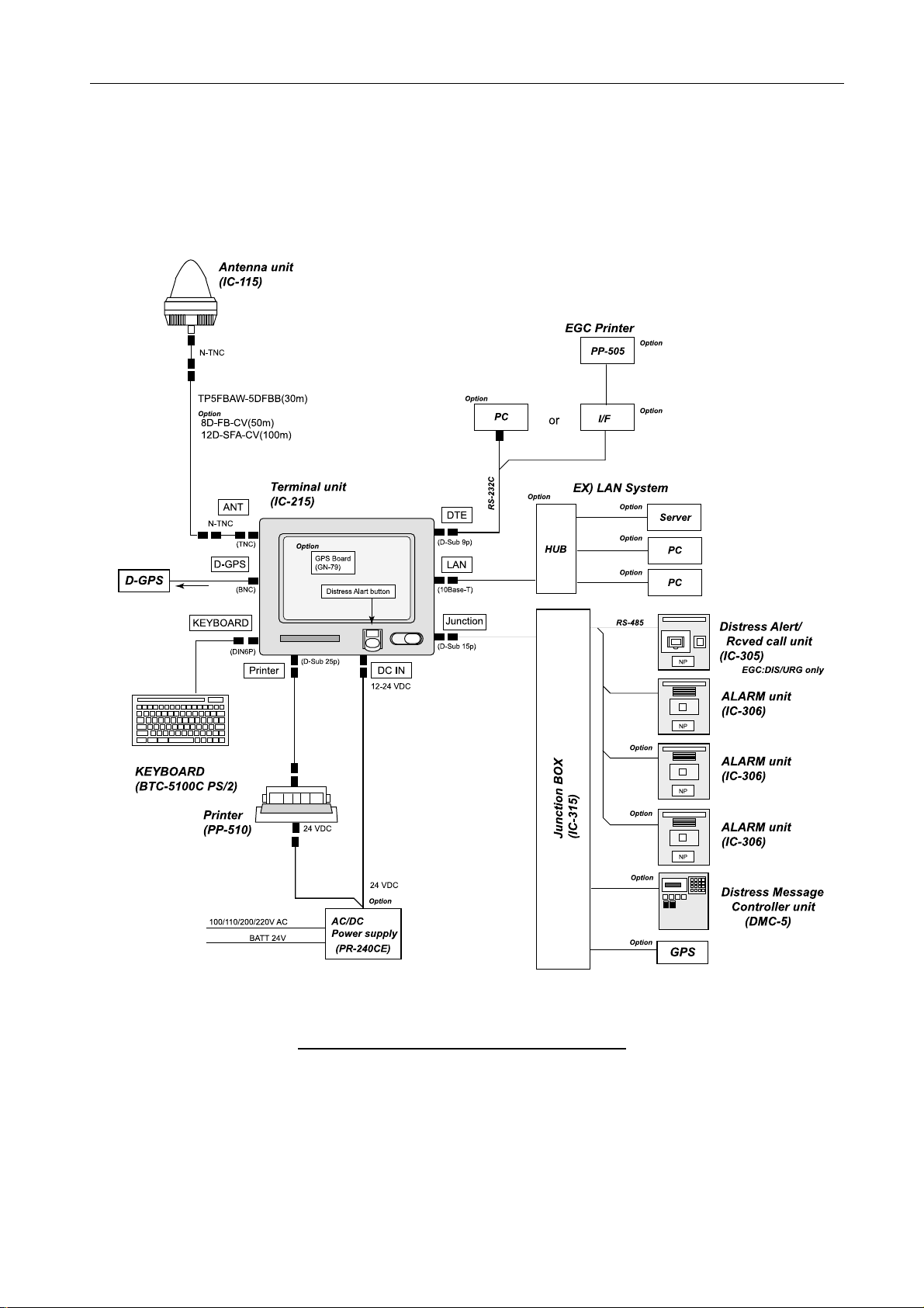
1.2 Configuration
To use the cable other than TP5FBAW-5DFBB, optional N-TNC converting cable is
needed to both the antenna unit and the terminal unit.
Fig.1.2.1 Nera C system configuration
1-2
1.3 Connection
1.3 Connection
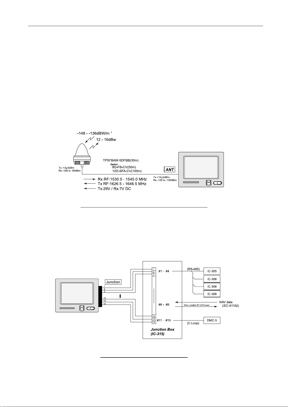
1.3.1 Antenna and terminal unit
The antenna unit, IC-115 and terminal unit, IC-215 are connected by the coaxial cable.
This coaxial cable includes 1530.0 MHz to 1545.0 MHz receiving RF signal, 1626.5
MHz to 1646.5 MHz transmitting RF signal, 1575.42 MHz receiving GPS RF signal
and the power supplied to the antenna unit. The transmitting voltage is +29 V DC and
the receiving voltage +7 V DC.
The loss of the coaxial cable is about 10 dB at 1.6 GHz.
To use the cable other than TP5FBAW-5DFBB, optional N-TNC converting cable is
needed to both the antenna unit and the terminal unit.
Fig.1.3.1 Connection of antenna unit and term inal unit
1.3.2 [Junction] port
[Junction] port is connected to the junction box (IC-315).
Fig.1.3.2 Connecting to Junction Box
1-3

1.3 Connection
1) Connecting the distress alert received unit and ALAM unit
The distress alert received unit: IC-305 and up to 3 ALARM units: IC-306 are
connected to port #1 to #4 in parallel. The electrical rating of port #3 and #4
(TD/RD-A/B) connecting line is RS-485. Each unit needs to be set for identification
such as DIS, RCV-1, 2 and 3. And IC-305 and IC-306 are controlled by the setting of
“Command Window” in [F8]-2: system menu. Terminal unit communicated to these
units recognizes each unit by this setting.
2) Connecting NAV data (IEC-61162)
Ports #6 and #7 (TD-A/B) are used for transmitting NAV data. To transmit NAV data,
optional GPS receiving board (GN-79) is needed.
Ports #8 and #9 (RD-A/B) are used for receiving NAV data. The external GPS data
needs to be connected.
3) Connecting DMC-5
Ports #11 to #15 are DMC-5 connecting terminals. The electrical rating is C. Loop.
DMC-5 is controlled by the setting of “Command Window” in [F8]-2: system menu.
Note) RS-485
This is like RS-422 (balanced). It is half-duplex, and not just point-to-point but like
Ethernet since all devices (nodes) on it share the same “bus”. The driver output signal
level (loaded minimum) is +/-1.5 V.
1-4
1.3 Connection
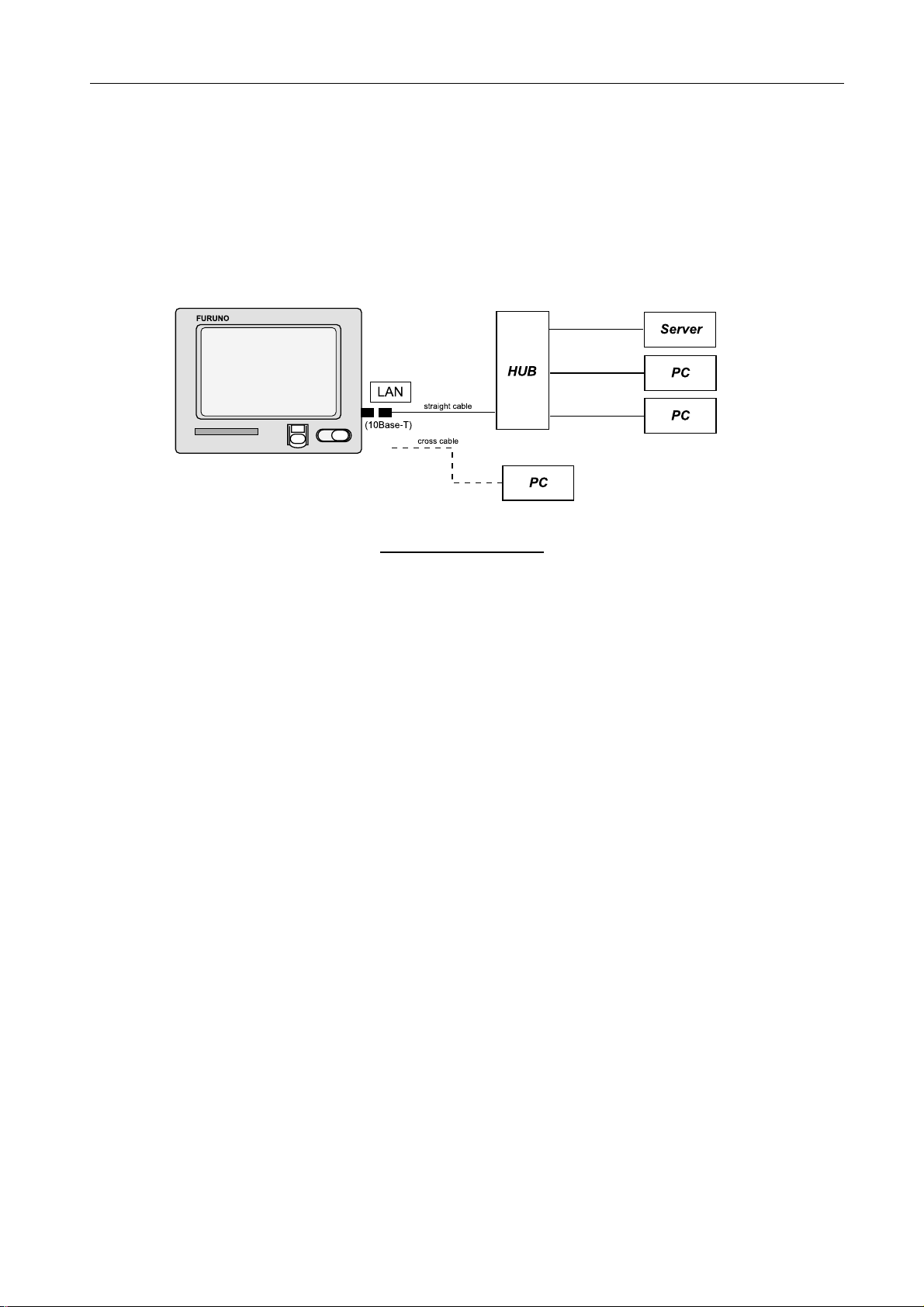
1.3.3 [LAN] port
10Base-T, RJ-45 connector is used for Ethernet LAN. Terminal unit includes the mail
gateway function such as SMTP and POP3 so that the E-mail communication is
available from the PC connected to LAN by using Inmarsat C.
Up to 32 k bite data is sent from the Inmarsat C.
Fig.1.3.3 LAN system
1.3.4 [DTE] port
The specification of the input/output signal is RS-232C. Data communication is
available by connecting PC. When installing another terminal unit(PC), it should be
connected to [DTE] port by using the straight cable.
Commercial printer for Windows and PP-510 can be connected to “Printer” port on PC.
Printer setting is made through “Printer setting” menu ([F1]-8).
With the commercial printer, error messages, such as “WARNING, TROUBLE: XXX”
are not printed out.
1.3.5 [D-GPS] port
The receiving signal, 1530 MHz to 1545 MHz is output at the level of 50Ω, -103 dBm
to -86 dBm.
1-5
2.1 Configuration
Chapter 2. Block Description
2.1 Configuration
2.1.1 Nera C
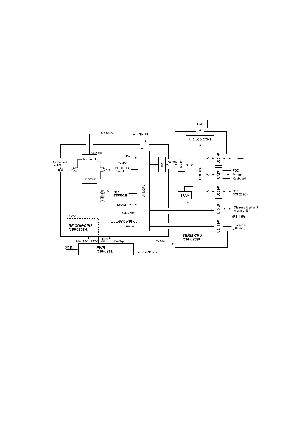
Fig.2.1.1 shows the block diagram of the terminal unit, Nera C.
Fig.2.1.1 Block diagram of terminal unit , Nera C
2-1

2.1 Configuration
2.1.2 Boards in each unit
Table 2.1.1 lists the function of boards in each unit.
Table 2.1.1 Boards in each unit
Unit Board Function Remarks
1) Consisting of RF amplifier circuit and
the dielectric filter which dividing
Antenna
(IC-115)
Terminal
unit
(IC-215)
ANT RF
(16P0207)
Daisy loop
type antenna
RF
CON/CPU
(16P0208A)
TX/RX signal.
2) Changing TX and RX circuit by
antenna supplied voltage, TX 29 V/RX
7 V.
3) Automatically the transmission is
stopped when the temperature of the
board is over +95 °C.
- Receiving gain: 36 dB+
max. (Output: -108 to -90 dBm)
- Transmitting gain: Outputs +42dBm by
inputting +3 +
- Continuous-time of transmitting: 8
minutes
Directional characteristics
Horizontal: Non-directivity
Vertical: EL= 90°: 0 dBi and more
EL= 5°: +1.3 dBi and more
Polarization
Right circular polarization wave
RX: Changing RF signal, -120 dB to –100
dBm from antenna unit to I signal and
Q signal of the base band.
After decoding, the signal is sent
Term CPU board.
TX: After encoding the data from Term
CPU board, the data is modulated at
DDS and changed to TX RF signal,
+14 dBm.
Oscillation circuit: The following
frequencies are oscillated at DDS and
PLL synthesizer circuit.
TX=1626.5 MHz to 1646.5 MHz
RX=1530 MHz to 1545 MHz
EEPROM(U15): Memorizing FW/RT ID,
DNID and ENID. See page 2-27.
3 dBm
3 dB NF=2.0 dB
The difference from
Nera C12.
1) The diplexer is changed
to the dielectric filter.
2) The circulator is not
installed.
3) TX/RX voltage is changed
from +29/18 V to +29/7 V.
4) The continuous-time of
transmitting is limited.
When replacing RF
CON/CPU board,
remove the EEPROM(U15)
from old board and put it on
the new board.
2-2

2.1 Configuration
I/F rating
- Printer: Centronics
- PC: RS-232C
TERM/CPU
(16P0209)
Communicating with followings;
LCD, Printer, PC, Distress Alert Received
unit, ALERT unit, NAV data, Ethernet,
FDD, keyboard and RF-CON/CPU board.
- Distress Alert Receiv ed/
ALERT unit : RS-485
- NAV data inputting:
GGA, GLL, WPL, VTG,
RMA, RMB, RMC, MTW,
DBT, VDR, BWC, BWR
and ZDA
Switching power supply
Input voltage: 10.8 V to 31.2 V
Maximum input current: 13 A (When
inputting 10.8 V)
Output voltage: 29, 7, 6.5, 3.3, 5 V and
LCD power supply
Detecting status monitor signal:
- CHECK V: Antenna Power supply
- ANT C: Send Level
Terminal
unit
(IC-215)
PWR
(16P0211)
Changing ANT TX/RX power supply by
HPA ON signal
SW
(16P0212)
PWR C
(16P0214)
GPS
Receiver
(GN-79)
MCN
(16P0226)
Consisting of the distress alert button, the
buzzer and the power switch.
Consisting of the bypass capacitor for
EMC and the power reverse
connection protector diode.
12 CH parallel GPS receiver. Outputs
GLL, GGA, VTG, RMC, GS V and ZDA by
IEC-61162 data.
Relay board for wiring between Term CPU
board and LCD.
Option
FDD FDD for 2HD and 2DD FD
640x480 dots and 262,144 color display.
LCD
(In specification, IC-215 display uses 16
colors.)
Junction
box
(IC-315)
Distress
Alert
Received
unit and
ALERT
unit
(IC-305/
306)
DIST
(16P0213A)
RCV
(16P0213B)
Junction box for [JUNCTION] port of
terminal unit. Terminal board only.
Consisting of I/F and the driver which
communicates with Term CPU board by
RS-485 signal conductor.
Communication contents: The control of
the buzzer and the button and the
recognition of the unit number.
Option
IC-305 and IC-306 have the
same board.
Maximum of 3 IC-306 unit
and IC-305 unit are
connected in parallel.
The setting of the unit
recognition number is
necessary.
2-3
2.2 Antenna unit, IC-115
2.2 Antenna unit, IC-115
The antenna unit consists of ANT RF board (16P0207), ANT B(16P0206) and the daisy
loop type antenna element.
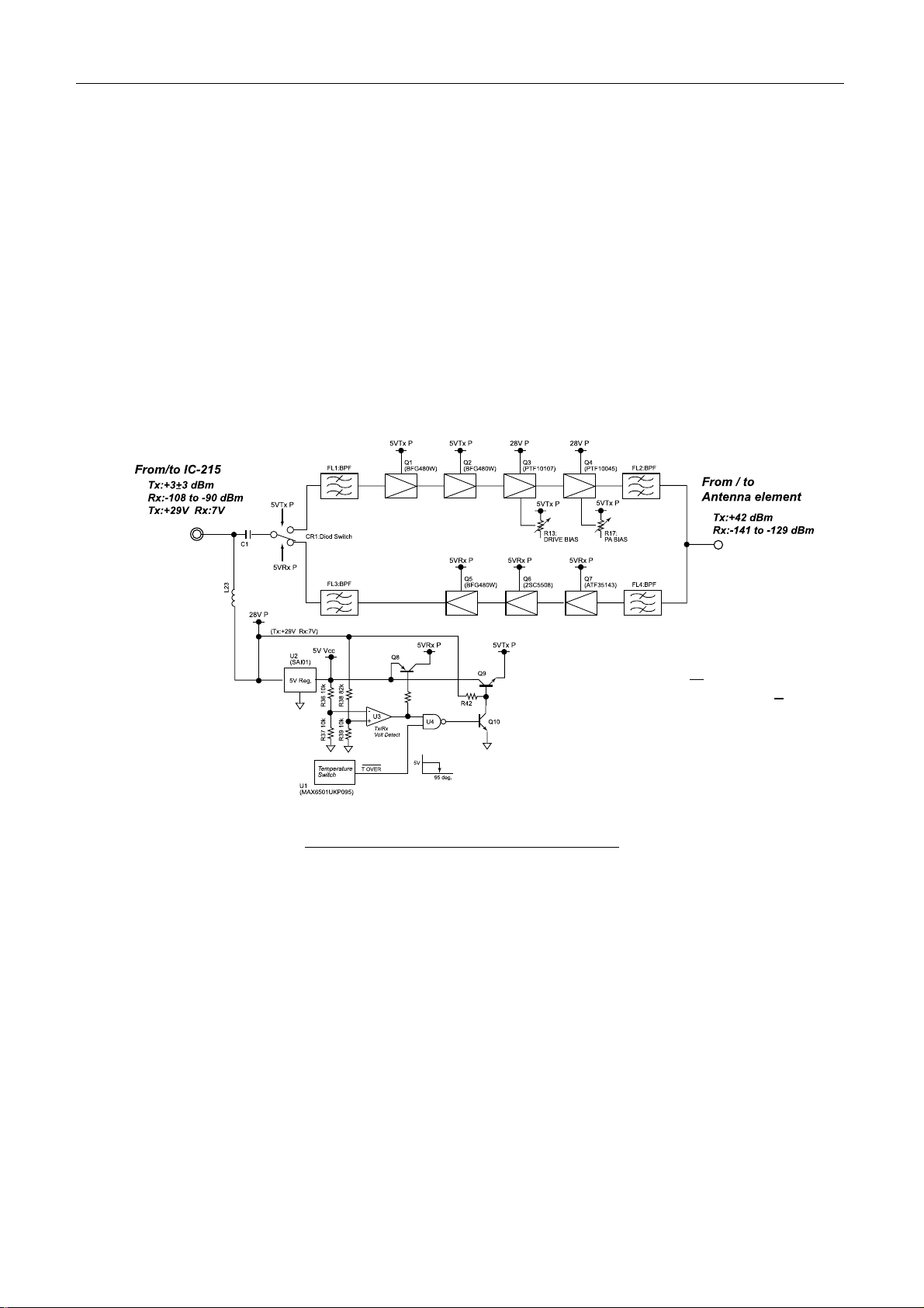
2.2.1 ANT RF board (16P0207)
ANT RF board consists of the transmitting RF amplifier circuit, the receiving RF
amplifier circuit, the voltage changing circuit of TX/RX circuit and the heat protecting
circuit. The band pass filter is installed at the input/output unit of RF circuit to divide
RF signal. Fig.2.2.1 shows the block diagram of the ANT RF board.
• Receiving gain: 36d B+ 3dB NF=2.0 dB max.
• Transmitting gain: Changing +3 +
42 dBm
• Continuous-time of transmitting: 8 minutes
3 dBm, to +
Fig.2.2.1 Block diagram of ANT RF board
To control the voltage changing of TX/RX circuit, the voltage, 29 V (TX)/7 V (RX)
supplied from the terminal unit is detected by the comparator, U3. The output controls
Q8 and Q9 to generate the voltage of 5 V RX P and 5 V TX P.
The heat protector is installed to stop the transmission automatically when the
temperature of the board is more than +95 °C. To detect the heat of the board, the heat
detecting switch, U1 is installed on the center of the ANT RF board. When detecting
+95 °C, 5VTx P is set to OFF via NAND, U4 to stop the transmission.
2-4
2.2 Antenna unit, IC-115
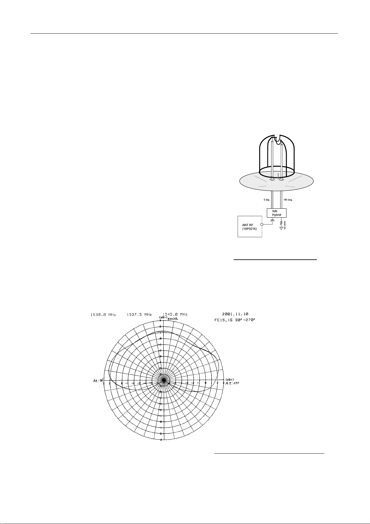
2.2.2 Antenna element
Antenna unit consists of the element, the 3 dB hybrid and the reflector.
The antenna unit is called “DAISY LOOP ANT antenna”. ANT RF output,
42 dBm of 1.6 GHz is radiat ed from the antenna by 14 dBW of EIRP. The receiving
signal of the power flux density, -148 dBW/m
ANT RF receiving circuit with the level of –141 dBm to –129 dBm.
- TX/RX antenna gain: more than 1.3 dBi
(When the antenna elevation angle is +5°.)
- Directional characteristics
Horizontal: Non-directivity
Vertical:
1.3 sin to 1.5 sin (El - 5) dBi
(+5° < El <+90°)
-2.7 cos + 4 cos [4.5 (cos - 5) ] dBi
(-15° < El <+5°)
- Polarization:
Right circular polarization wave
2
to –136 dBW/m2 of 1.5 GHz is input to
Fig.2.2.2 Antenna element
Fig.2.2.3 shows the vertical directivity diagram at 1.5GHz band.
(Horizontal Directivity: Non-directivity)
Fig. 2.2.3 Vertical directivity diagr am
2-5
2.3 Terminal unit, IC-215
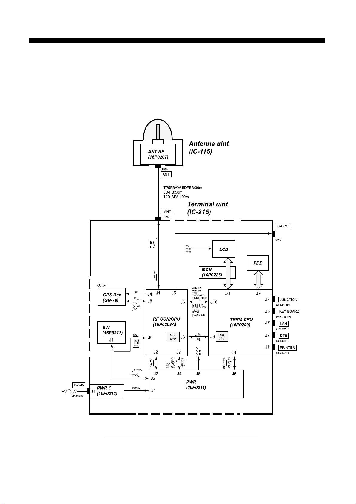
2.3 Terminal unit, IC-215
The terminal unit consists of PWR board (16P0211), RF CON/CPU board (16P0208A) and
TERM CPU board (16P0209).
RF CON/CPU board and TERM CPU board are communicated by RS-232C.
The transmitting control unit such as Nera C 10/11/12 has the function of RF CON/CPU
board, and the terminal unit such as IC-511/IB-581 has the function of TERM CPU board.
Fig.2.3.1 shows the configuration of the terminal unit.
Fig.2.3.1 Configuration of Terminal unit
Note) When changing RF CON/CPU board, use EEPROM, U15 which memorizes
the ID (Forward/Retune ID) for communication, the ENID (Fleet Net ID) for
receiving EGC Fleet Net broadcasting, DNID (Data Network ID) for the data
reporting service.
2-6
2.3 Terminal unit, IC-215
2.3.1 RF CON/CPU board (16P0208A)
The following describes the function of RF CON/CPU board.
Analog part
- Dividing the received RF signal to [D-GPS] terminal for D-GPS decoder.
- Dividing the received RF signal to GPS receiving board (GN-79, option).
- Changing the received RF signal to the IF signal: 1.2 kHz.
- Generating the 400 kHz TX/RX frequencies at PLL synthesizer circuit. (TX: 1626.5 MHz
to 1646.5 MHz Rx: 1530.0 MHz to1545 MHz)
- BPSK modulating at DDS.
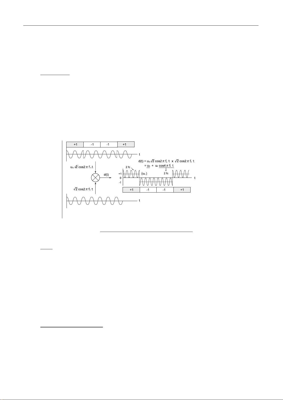
Fig.2.3.2 shows the synchronizing detection circuit.
Fig.2.3.2 Synchronizing detection circuit
CPU
- Controlling communication protocol of Inmarsat C.
- TX/RX signal processing
- TX/RX changing
- Controlling AGC, PLL and DDS circuit
- Communicating with TERM CPU
- Controlling the Distress Alert Received unit(IC-305) and the Alarm unit(IC-306)
- Handling IEC-61162 (NMEA) data
- Monitoring SYN, CHECK V (the supplied voltage for the antenna) and ANT C (Antenna
current)
Memory (see page 2-27)
- RAM: Backed up for 72 hours
- EEPROM: Memorizing FW/RT ID, ENID, DNID
2-7
2.3 Terminal unit, IC-215
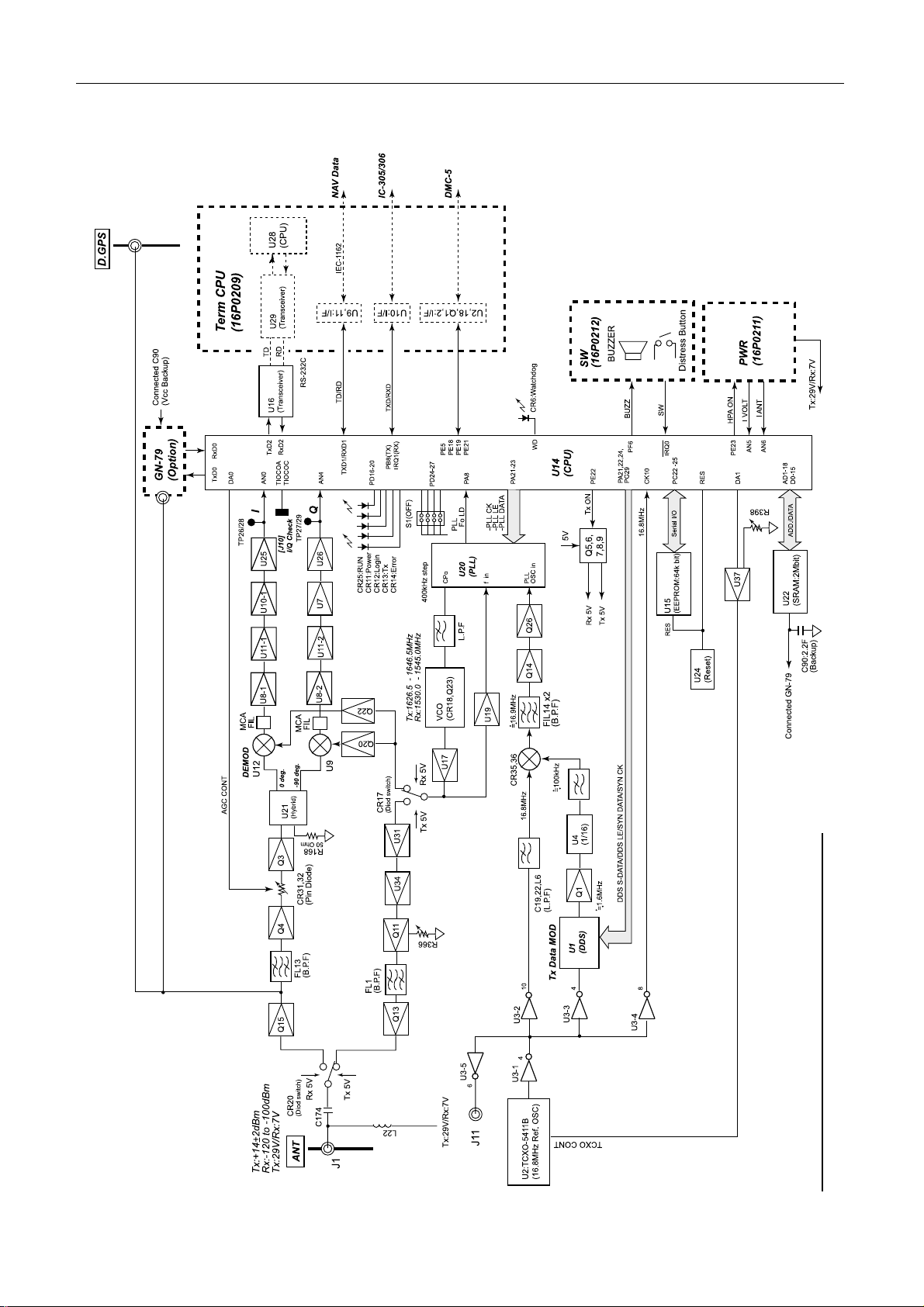
Fig.2.3.3 Block diagram of RF CON/CPU boar d
2-8
2.3 Terminal unit, IC-215
1) Receiving part
Receiving circuit
The RF signal from the antenna unit is input to the receiving circuit by the diode switch,
CR20. FL13 of the receiving circuit is B.P.F of 1.5 GHz.
The BPSK modulating RF signal is changed to 1.2 kHz intermediate frequency at Hybrid
(U21) and DBM (U12 and U9) and then input to CPU (U14) as I and Q signals. The local
oscillator frequency input to DBM is 1.2 kHz lower than the receiving frequency.
The interference from MCA: Multi-Channel Access (1513 MHz to 1525 MHz) is reduced
by L.P.F consisted of inductor and capacitor (about 5 MHz) after changing the frequency at
U12/U9 (IF: 1.2 kHz).
At Hybrid, U21 and DBM, U12 and U9, the I signal and Q signal of 1.2 kHz IF signal are
taken from the BPSK modulated receiving RF signal to input to CPU, U14.
The Lissajous waveform is monitored by [J10]. AGC is controlled by the pin diodes, CR31
and CR32. The AGC signal is generated from the I signal and Q signal input to CPU. The
BPSK modulating signal is processed at U14 to send message to TERM CPU board.
The process of NCS/LES TDM channel signal processing at U14 (CPU) is as follows.
BPSK de-modulation (I signal and Q signal)
-- Detecting the unique word (Tuning the flame) -- De-permuting – De-Interleaving
-- Viterbi decoding -- De-scramble -- Taking the packet --
Sending to TERM CPU board
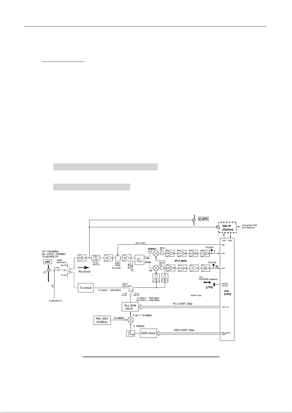
Fig.2.3.4 shows the block diagram of the RF CON/CPU receiving circuit.
Fig.2.3.4 Block diagram of RF CON/CPU r eceiving circuit
2-9
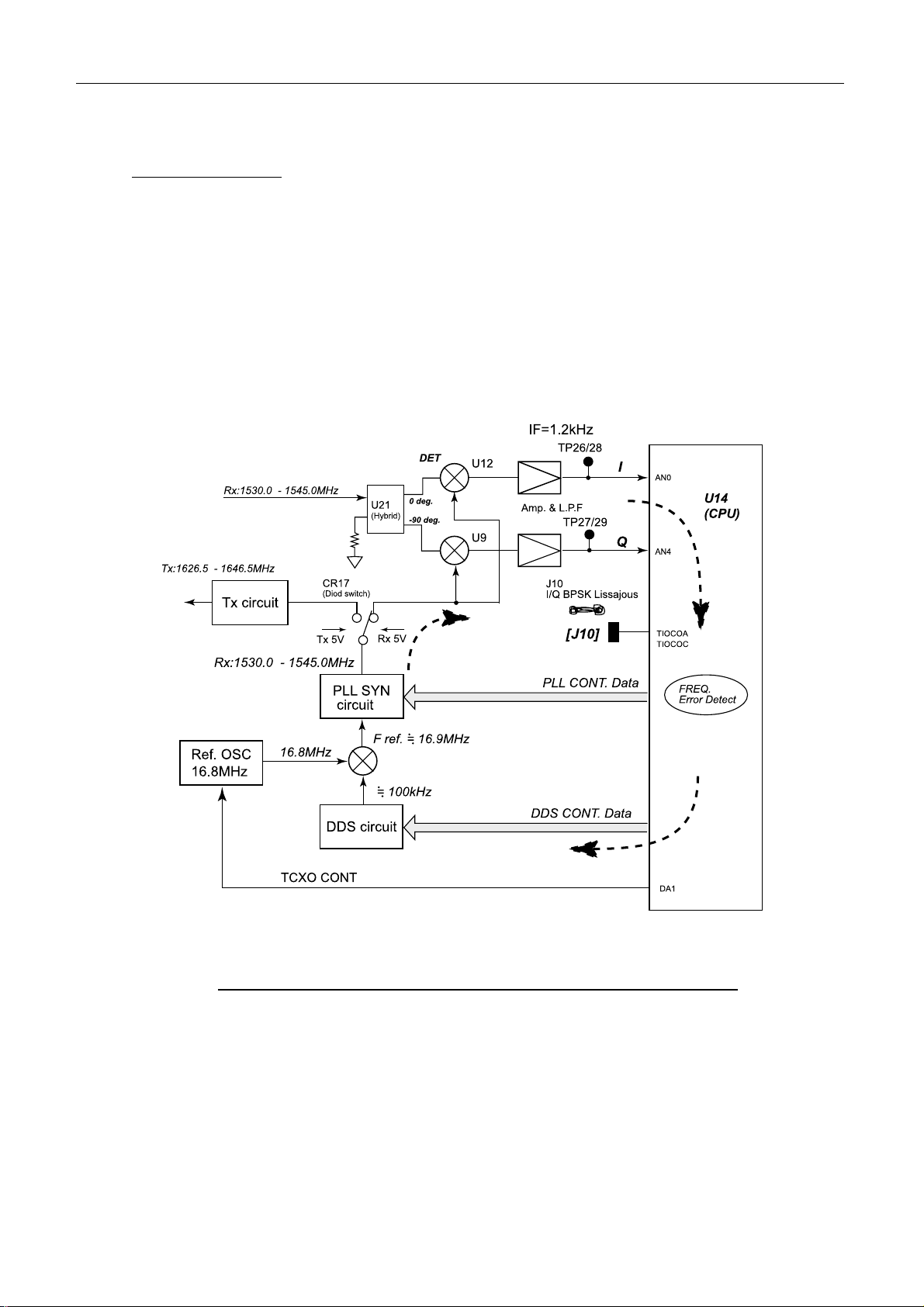
2.3 Terminal unit, IC-215
Frequency control
For example, when the receiving frequency from the satellite differs from the carrier
frequency input to the de-modulating circuit, the error rate is increased.
CPU detects the frequency difference and the phase difference of I signal and Q signal. The
detection data controls the frequency of the TX/RX PLL synthesizer oscillator (TCXO:
16.8 MHz) so that the output frequency is equal to the receiving frequency by controlling
the PLL synthesizer output frequency.
The standard oscillator, 16.8 MHz is controlled by the 1 kHz step at the first FFT.
Fig.2.3.5 shows the block diagram of the RF CON/CPU receiving frequency control.
The frequency complemented value is checked at “REF Offset Freq” in Status display.
“OK” appears when the Offset Freq. is less than 150 Hz.
Fig.2.3.5 Block diagram of RF CON/CPU r eceiving f requency control
2-10
 Loading...