

Page 1
neo2000®Gamma Detection System
6
Service Manual
Models 2000 & 2100
Manufacturer:
Neoprobe Corporation
425 Metro Place North, Suite 300
Dublin, Ohio 43017-1367 USA
Tel: +1 (614) 793 7500
Fax: + 1 (614) 793 7531
008
Medical Electrical Equipment
With respect to electrical shock,
fire, and mechanical hazards.
only.
00-0059 Rev B © 2001 Neoprobe Corporation
Authorized representative:
AR-MED, Ltd.
Runnymede Malthouse
Egham TW20 9BD, UK
Tel: +44 (0) 1748 497851
Fax: +44 (0) 1748 497801
“neo2000” is a registered trademark of Neoprobe Corporation.
“BlueTip” is a trademark of Neoprobe Corporation.
Page 2
Table of Contents
1. Introduction 1-1
1.1 System Warnings, Cautions and Notes 1.1-1
2. Specifications 2-1
3. Technical Overview 3-1
4. Diagnostic Troubleshooting 4-1
5. Disassembly, Service Part Installation and Re-assembly 5-1
6. Performance Verification 6-1
7. Disclaimers 7-1
8. Service Policy 8-1
i
Page 3
Table of Contents (continued)
9. Warranty 9-1
10. Notices 10-1
Appendix A
A.1 neo2000
A.2 neo2000 Grounding & Isolation Diagram A.2-1
A.2 Front Housing Assembly A.3-1
A.3 Rear Housing Assembly A.4-1
Appendix B Neoprobe Authorized Service Parts B-1
Appendix C Service Checklist C-1
®
Functional Schematic A.1-1
ii
Page 4
Introduction
1
Purpose
This manual provides the necessary
information for an experienced biomedical
instrumentation technician to perform
routine service operations on the Neoprobe
neo2000® Gamma Detection System
(neo2000) in Model 2000 and 2100
configurations.
Scope
This manual gives instructions for the
servicing of the neo2000, including
diagnostic sequences to troubleshoot and
isolate failures, assembly sequences
required to remove and replace suspect
service parts, and performance verification
sequences to ensure that the performance
of the repaired unit meets Neoprobe
specifications. This manual does not
include any servicing capability for the
Neoprobe gamma detection probes, cables
or accessories. These items are not
serviceable in the field. This manual does
not provide detailed repair procedures and
technical documentation to isolate failures
to the lowest possible level. It
also does not discuss how to
perform surgery and procedures
for nuclear medicine.
The intent of this manual is not
to support the remanufacture
and resale of the neo2000 by
third parties.
Servicing Personnel
This manual is intended for use
by biomedical instrumentation
technicians and other
individuals who are familiar
with the routine servicing and maintenance
of medical electronic instrumentation. (For
additional information see Chapter 7.)
Those individuals should also be
thoroughly familiar with the neo2000
Operation Manual.
Customers are not authorized to perform
service during the initial one (1) year
period.
Training
This manual in conjunction with the
neo2000 Operation Manual provides all
the information that should be necessary
for a competent biomedical
instrumentation technician to perform the
authorized servicing operations. Neoprobe
does not provide any supplemental training
in the servicing of the neo2000.
1-1
Page 5
Introduction (continued)1
Customer Feedback
Neoprobe understands the importance of
feedback to continual quality
improvement, and encourages users and
servicing personnel to provide any
suggestions for improving the products
and this manual. Please forward any
suggestions to:
Neoprobe Corporation
425 Metro Place North, Suite 300
Dublin, OH 43017-1367
Attn: Technical Support
or telephone:
(800) 793 0079 (USA only) or
+1 (614) 793 7500
or email:
Note: In the unlikely event of a malfunction or failure,
Neoprobe recommends that owners of neo2000
instruments contact Neoprobe for service.
®
1-2
Page 6
1.1
Warnings, Cautions and Notes
Overview
Read this section before servicing
the neo2000®. Included below are
warnings, cautions and notes for
safe service of the neo2000.
Definitions
Service Part: Component used in
the neo2000 that is available as a
replacement part for order from
Neoprobe by registered owners of
Neoprobe neo2000 products.
Warning: Specific information
provided to the service technician to
advise of improper servicing of the
device that could present potential
harm to the service technician, user
or patient and/or could result in
irreparable damage to the device or
property.
Caution: Specific information
provided to the service technician to
prevent the incorrect servicing of the
device which may affect performance
or safety of the device.
Note: General information provided
to the service technician to further
explain or clarify the proper servicing
of the device.
Warnings
• Only biomedical instrumentation
technicians or other individuals who
are familiar with the routine servicing and maintenance of medical
grade electronic instrumentation
should service the neo2000.
• Neoprobe shall have no liability for
any incident resulting from improper
servicing of the neo2000, or from the
use of any service parts that are not
obtained by authorized Neoprobe
sources of supply. (see chapter 9)
• Before servicing, complete the
necessary cleaning and inspection
process. (see chapter 4.2 of the
neo2000 Operation Manual)
• Disconnect the power cord from the
power outlet before opening.
• Do not open in the presence of
fluids, flammable anesthetics or
other explosive gases.
• The internal electronics of the
neo2000 are sensitive to damage
from electrostatic discharge (ESD).
Use appropriate precaution when
opening and servicing the unit.
• Neoprobe Corporation does not
support the remanufacture and
resale of the neo2000 by third
parties.
• Returned products must be properly
decontaminated in accordance with
all applicable regulations for
biohazardous material.
• Proper configuration of grounding
required for safety.
Cautions
• Replace wire ties and reroute wires
as they were initially found.
• Do not leave loose hardware inside
the console.
• Conduct normal in-house product
safety testing for the neo2000 after
servicing and before returning the
unit for use on patients.
1.1-1
Page 7
Warnings, Cautions and Notes (continued)1.1
Notes
• The volume knob may be damaged
by mechanical shock.
• In the unlikely event of a malfunc-
tion or failure, Neoprobe recommends that owners of neo2000
instruments contact Neoprobe for
service.
• Calibration & Preventive Mainte-
nance: The neo2000 is shipped
set to factory specifications.
Preventive maintenance is limited
to external cleaning of the
neo2000, fuse replacements and
functional diagnostics.
®
• Replacement of certain items will
require reprogramming of the unit.
Contact Neoprobe to arrange for
reprogramming of the unit.
• Regarding Year 2000 compliance,
the neo2000 Gamma Detection
System does not use a Real Time
Clock, and subsequently is not
adversely affected by Year 2000.
• “Error 1” or “Error No Probe” is a
normal operating message when
no probe is present. Check probe
and cable connections.
1.1-2
Page 8

Specifications2
Product Specifications
The neo2000® complies with
the following specifications.
Service replacement parts
ordered through Neoprobe also
comply with the appropriate
specifications listed. Personnel
performing service on the
neo2000 must understand
these specifications and must
ensure that all servicing
activities performed on the
neo2000 do not compromise
any of these specifications.
Product Classification Standard or Regulation
System: Class I, Exempt USA, 21 CFR § 892.1320
Class IIa Europe, Medical Device Directive
Class II Canada, Therapeutic Device Regulation
Class II Australia, Therapeutic Device Regulation
Model 2000 Type B EN 60601-1/2
Model 2100 Type BF EN 60601-1/2
(1)(2)
(2)
Console: Explosion Equipment not suitable for use in the
presence of Flammable ANASTHETIC
MIXTURE WITH AIR or OXYGEN or
NITROUS OXIDE
Fluid Ingress Ordinary Equipment
Mode of Operation Continuous Operation
Degree of Mobility Stationary, non-mobile
Protection against Fused and removable power cable
electrical shock
BlueTip
TM
Fluid Ingress IPX4
Probes
(1)
The degree of protection from electrical shock is based on the system configured with
reusable metal encased probes (Model 1017). When used with the BlueTipTM Probes (Model
2001, 2002, & 2003), the system is Type BF due to the mechanical isolation barrier the
plastic material provides.
2)
Product safety testing of the initial design is certified through laboratory testing conducted
by a certified third party testing laboratory. Ongoing production testing assures that each
device continues to comply with these criteria.
2-1
Page 9
2 Specifications (continued)
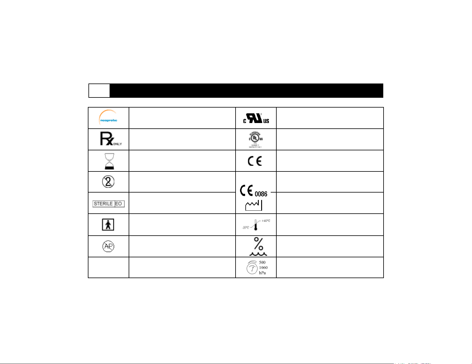
IPX4
Neoprobe Corporation logo
In the U.S.A., Caution: Federal Law
restricts this device to sale by or on the
order of a physician
Use by
Do not reuse
Sterile using Ethylene Oxide
Type BF
Not for use in the presence of flammable
anesthetics
Splash-proof equipment
Underwriters Laboratory (UL) recognized
symbol component
UL Classified device
CE Mark, Class I
CE Mark, Class II, Class I Sterile
Date of manufacture
Storage and Transit Temperature
Storage and Transit Pressure
Storage and Transit Humidity
2-2
Page 10
2 Specifications (continued)
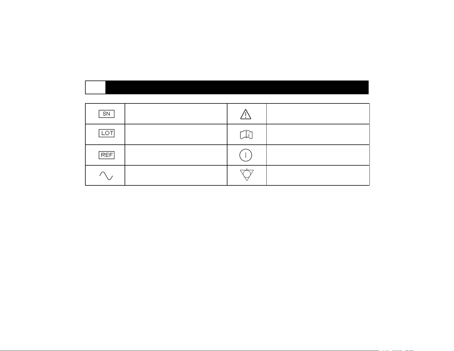
Serial number
Batch code
Catalog number
Alternating current
Caution: consult accompanying
documents
Consult instructions for use
Standby (push-push) (power on:
connections to mains; power off:
disconnection from mains)
Equipotentiality
2-3
Page 11
Technical Overview
3
Overview
This section describes the basic technical
features of the neo2000® console. Refer
to Appendix A.
Processing Architecture
The neo2000® contains two processors
with distinct functions: the central
processing unit (CPU) and the digital signal
processor (DSP). The CPU controls the
operator interface and some higher level
processing functions. The DSP performs a
majority of the processing of the probe
input signals including many of the
formatting and statistical processes
associated with counting input pulses. The
processors are located on separate circuit
boards and use a standard bus structure
with the CPU as the master of the bus.
Operator Inputs
Operator control over the console is
accomplished through the use of momentary pushbuttons. Most buttons have only
one function within a single operating mode.
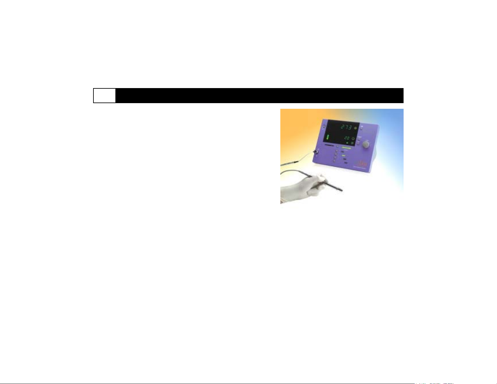
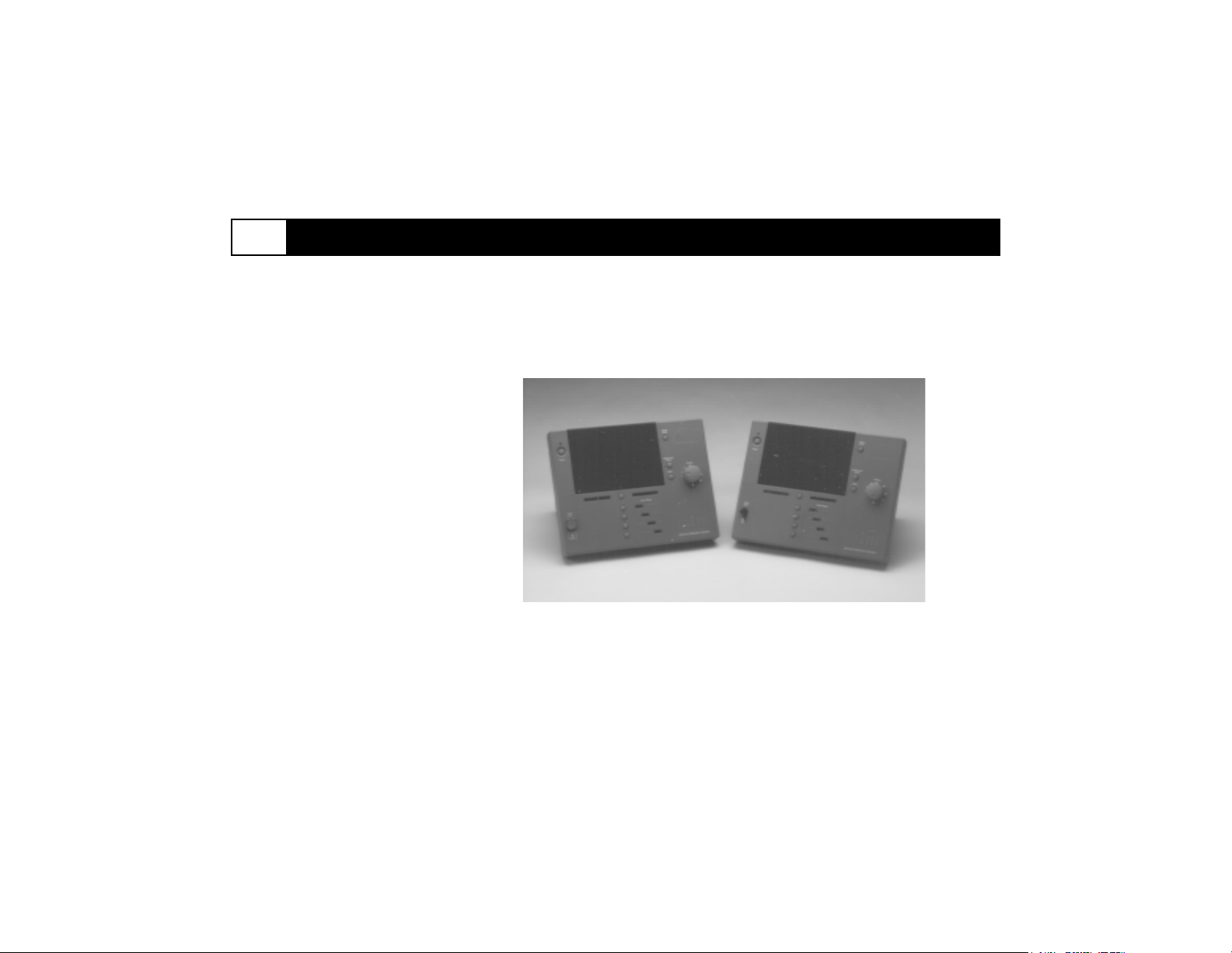
Figure 3-1. neo2000 Console (Left: Model 2100; Right: Model 2000)
3-1
Page 12
Technical Overview (continued)
3
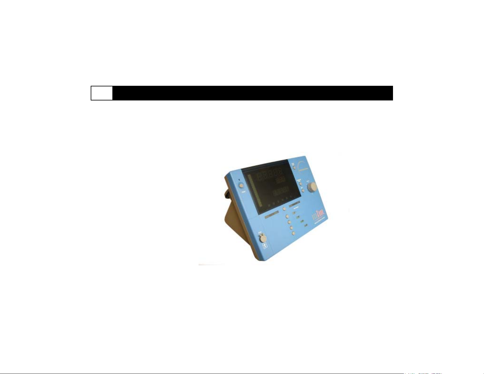
Volume control is accomplished
through use of a rotary input. To
maximize flexibility, this rotary input
is readable by the software and does
not directly control the audible
output level. Audible feedback of
button presses is provided electronically rather than mechanically.
Operator Outputs
Data from the console is presented to the
operator using both visual and audible
means. Operational state indicators are
provided to clearly indicate the operating
mode of the system to the user. Numeric
displays present quantitative data for
evaluation by the operator. A graphics
display and an audio speaker present
information in a qualitative manner.
Audible data is presented in order to allow
the surgeon to keep visually focused on
the patient. The audible output produces
data and status information simultaneously.
Electronic Input/Output (I/O) Ports
There are two serial I/O ports on the rear
of the console. These are used at the
factory to program the unit and for future
expansion.
Enclosure
The
enclosure
design
complies
with the
following
regulatory
requirements: 1)
EN 60601-11 drop test; 2)
EN 60601-1-2
electromagnetic
susceptibility and
emissions tests. To meet these
design requirements, a two piece
clamshell enclosure is used.
The enclosure has interlocking ribs
combined with a tongue and groove joint
to provide strength to pass the drop test.
Rigidity of the housing is obtained by
screwing the front and rear housings
together.
The walls of the housings are
angled to allow fluids to flow off
of the console. The tongue and
groove allows the placement of
a gasket to prevent liquid
ingress at the location of the
seam. The buttons are
designed to prevent liquid
entry without sacrificing
tactile feedback. External
components are resistant to
most common disinfectants used
to clean devices outside of the sterile
field.
Connectors and Cabling
The console contains both externally
accessible connectors as well as internal
cabling. Connectors and cables meet
applicable regulatory requirements and
environmental conditions.
3-2
Page 13
Technical Overview (continued)
3
A
E
B
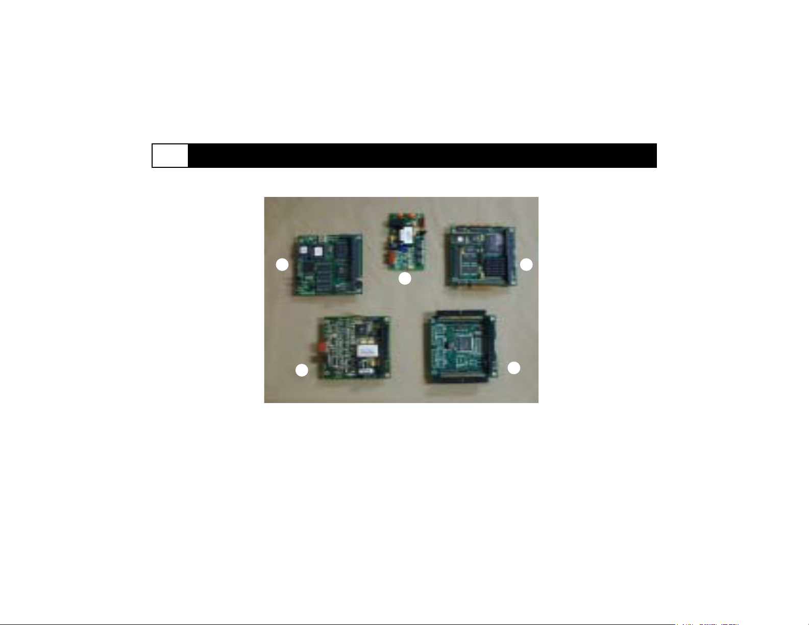
Figure 3-2. A. DSP Board B. PDM Board C. I/O Board D. CPU Board
E. PIM Board(Model 2100 only)
D
C
3-3
Page 14
Technical Overview (continued)
3
Technical Overview (continued)
neo2000® Components
CPU Board (P101)
The main CPU board is a 100/133 MHz
486DX based PC/104 board with onboard
programming of Flash memory, floppy/IDE
interface, serial ports, parallel port, and
serial boot loader capability.
I/O Board (P105)
The I/O board provides digital expansion
channels to meet the total I/O requirements for the neo2000.
DSP Board (P102)
The DSP is a Starburst DSP board
containing a DSP running at 32 MHz. This
processor is capable of both 32-bit
floating point and 32-bit fixed point
operations and has two timers. This board
also provides the necessary analog and
discrete I/O channels to control and
interface with the probe input circuitry.
PDM Board (P103* or P104**)
The pulse descriminator module (PDM)
board contains the interface circuitry for
the external probe. The major components
of the PDM board are the signal conditioning circuitry, the power circuitry and the
Pulse Discriminator.
PIM Board (P107**)
The probe isolation module (PIM) board
provides isolation circuits for the interface
to the external probe.
Main Board (P100)
The Main board serves as a mounting point
for most of the displays and switches in
the console and also serves as the
motherboard for the console.
Auxiliary Board (P106)
The auxiliary board serves as a junction
box for the rear enclosure half and acts as
a mounting point for the I/O connectors
and the radionuclide switch.
Power Supplies (P140, P141)
The +5V and +12V power supplies are
medical grade universal input supplies
which accept single phase power between
85 and 264 VAC and 47 to 63 Hz.
Cabling
There are a total of eleven cables and four
ground wires in the console. Refer to A.3.
The cables consist of:
Serial port cables (P120, P121)
I/O cables (2) (P122)
Auxiliary board cable (P132)
Line Filter cable (P124)
Power converter cable (P126)
Probe input cable (P128* or P129**)
PIM to PDM cable (P123**)
Speaker cable (P131)
Fan cable assembly (P150)
Line filter ground cable (P125)
Power converter ground cable (2 xP127)
Probe input ground cable (P130*)
* Specific to Model 2000
** Specific to Model 2100
3-4
Page 15
Technical Overview (continued)
3
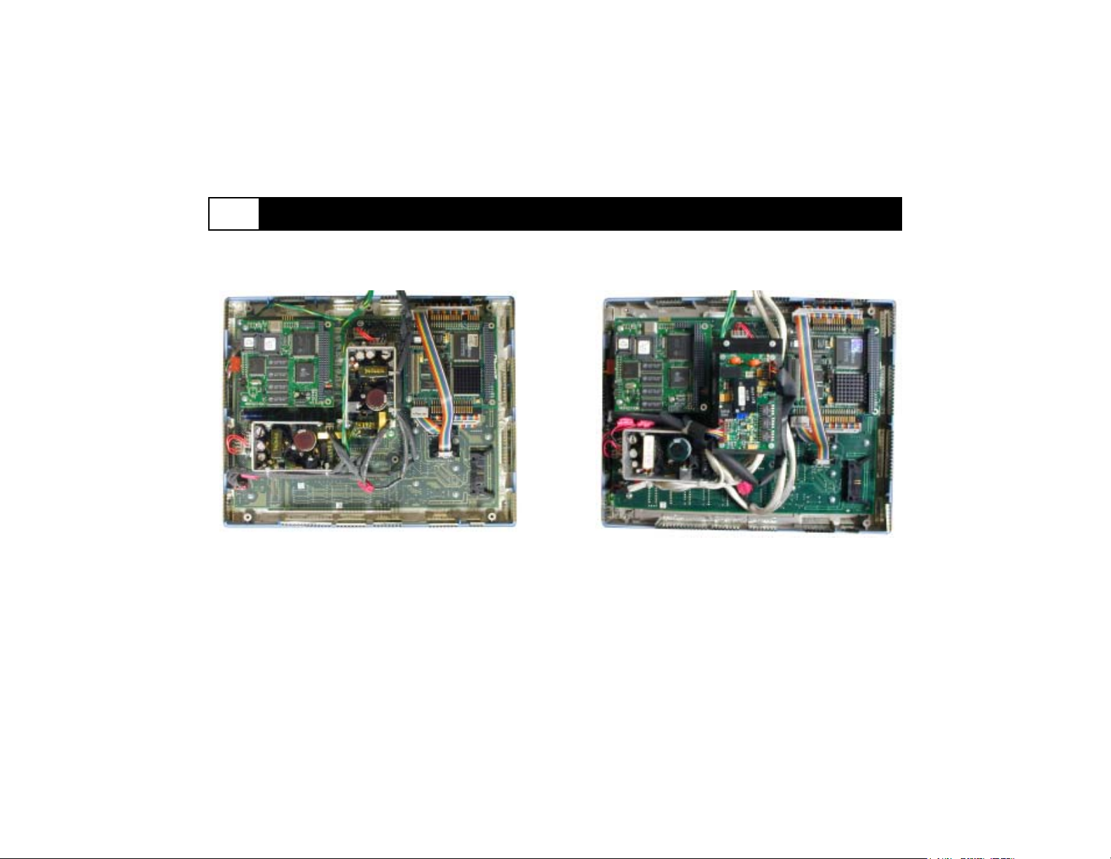
Figure 3-3. Top View of the neo2000® Front Assembly (Model 2000)
Figure 3-4. Top View of the neo2000 Front Assembly (Model 2100)
3-5
Page 16
Technical Overview (continued)
3
Safety Design
The neo2000
meets the applicable requirements of the
electrical safety and electromagnetic
compatibility regulations listed in the
Specifications chapter (2.0) of this service
manual.
The neo2000 Gamma Detection System is
classified as Class I, Type B (Model 2000)
or Type BF (Model 2100) equipment.
The Type B classification is broadly
applied to the Model 2000 system,
especially when the Model 2000 console is
operated with the 14 mm stainless steel
(Model 1017) probe. When configured
with one of the BlueTipTM Probes (Models
2001, 2002, 2003), the Model 2000
system is classified as Type BF meaning
that no earth connection exists between
the patient and the equipment. The Model
2100 is classified as Type BF when used
with any Neoprobe probes.
®
Gamma Detection System
Electromagnetic Compatibility
The inside surface of the neo2000
enclosure is covered with a conductive
coating to serve as a shield to electromagnetic radiation. The probe cable and the
probe are also shielded to meet emissions
and susceptibility requirements at the
system level.
Spring finger EMI gaskets are used to
bridge the enclosure seam between the
front and rear housings without exceeding
electrical safety creepage and clearance
requirements.
3-6
Page 17
Technical Overview (continued)
3
Personnel performing service on the neo2000® must be familiar
with the requirements contained in the applicable regulations for
electrical safety. The following features of the design must be
maintined after any servicing operation to ensure compliance with
these regulations:
Electrical Safety Checklist
Green/yellow wires securely fastened
Over insulation on all wiring
All connectors fully mated
Fluid ingress gasket properly installed in housing joint
No conductive items protruding from the device
(e.g. housing joint, speaker or fan vent)
Neoprobe Corporation recommends that those servicing the
neo2000 use this list as an Electrical Safety Checklist prior to
reassembling the unit.
Personnel performing service on the neo2000 must be familiar
with the requirements contained in the applicable regulations for
EMC compliance. The following features of the design must be
maintained after any servicing to ensure compliance with EMC
regulations:
EMC Compliance Checklist
EMI fingers securely fastened and not broken
No wires or EMI fingers protruding from housing
Neoprobe Corporation recommends that those servicing the
neo2000 use this list as an EMC Compliance Checklist while
reassembling the unit.
3-7
Page 18
Diagnostic Troubleshooting
4
Proper System Configuration
The table below gives solutions to correct some problems if the neo2000® Gamma Detection System is not operating properly. (Also,
see chapters 4.1 & 5 of the neo2000 Operation Manual)
Failure Sympton
Blank screen on
power-up
Potential Cause
Power cord failed or not connected
Fuse blown (Note: system requires
both fuses for operation)
Action
Confirm power cord is connected; replace if necessary
Confirm continuity of fuses; replace if necessary
Failed power switch
Failed line filter
Failed +12v power supply
Failed +5V power supply
Failed Power Converter Cable
Failed Line Filter Cable
Failed CPU board
Confirm power-on LED not illuminated and cooling fan not
operating; replace power switch if necessary
Confirm continuity through line filter; replace if necessary
Confirm power-on LED illuminated (operates directly from
+12V supply)
Confirm operation of cooling fan (operates directly from +5V
supply)
Confirm continuity of power converter cable; replace if
necessary
Confirm continuity of line filter cable; replace if necessary
Replace CPU board
4-1
Page 19
Diagnostic Troubleshooting (continued)4
Failure Sympton
“Error 1“
condition on
power-up or
during operation
with probe
connected
Potential Cause
Failed Probe
Failed probe cable
Failed Probe Supply voltage from
neo2000
Failed PDM Board
Failed I/O Board
®
Action
Confirm performance with another probe; replace if necessary
Confirm performance with another probe cable
Confirm continuity, check for shorts
Replace if necessary
Confirm +12V output at probe input connector
If no +12V output observed:
Check for physical damage to probe input connector; replace
if necessary
Confirm continuity, check for shorts of internal probe input
cable, replace if necessary
Check +12V output from PIM board (2100)
Confirm +12V ouput from PDM board (2000); replace if
necessary
Confirm +12V input to PIM board; replace PIM to PDM cable
if necessary
Replace PDM board
Replace I/O board
4-2
Page 20
4 Diagnostic Troubleshooting (continued)
Failure Symptom
neo2000® fails to
display “Error 1”
condition when
probe not
connected
*“Error 2” or
*“Error 3”
conditions on
power-up or
during operation
*“Error 4”
conditions on
power-up or
during operation
*“Error 5”
condition on
power-up or
during operation
*“Error 5.2”
condition during
operation
* If error persists, contact Neoprobe Corporation for additional technical support.
Potential Cause
Failed PIM board (2100)
Failed PDM board
Failed I/O board
Failed CPU or Main board
Failed DSP board
Failed Main board
Failed DSP board
Failed Main board
CPU stack over-flow
Action
Replace PIM board (2100)
Replace PDM board
Replace I/O board
Cycle power to unit. Return for service if condition persists.
Replace DSP board
Replace Main board
Replace DSP board
Replace Main board
Cycle power to reset CPU; if condition persists, replace CPU
board
4-3
Page 21
4 Diagnostic Troubleshooting (continued)
Failure Symptom
*“Error 6”
condition on
power-up or
during operation
Display shows
“Idle BLE” on
power-up
Display freezes or
locks-up during
operation
No response from
neo2000® input
control buttons
Potential Cause
Failed DSP board
Failed Main board
Application not properly programmed
Failed CPU board
Failed Main Board
Failed Main Board (front panel
buttons)
Failed Auxiliary Board (Radionuclide button)
Auxiliary Board Cable failure
(Radionuclide button)
Failed I/O Cable
Failed I/O Board
Action
Replace DSP board
Replace Main board
Return unit to Neoprobe for programming
Replace CPU board
Replace Main board
Replace Main board
Replace Auxiliary board
Confirm connections, continuity and no shorts in auxiliary
board cable; replace if necessary
Confirm connections, continuity and no shorts in I/O
cable(s); replace if necessary
Replace I/O board
* If error persists, contact Neoprobe Corporation for additional technical support.
4-4
Page 22
4 Diagnostic Troubleshooting (continued)
Failure Symptom
No response or
intermittent
response to
known radiation
source
Potential Cause
Incorrect energy threshold selected
Failed probe
Failed probe cable (external cable)
Failed Probe Input Cable (internal
cable)
Failed Probe Bias Voltage
Action
Confirm that proper radionuclide is selected on neo2000
Confirm performance with another probe; replace probe if
necessary
Ensure cable connectors are dry
Confirm performance with another probe cable
Confirm continuity, check for shorts
Replace probe cable if necessary
Confirm continuity, check for shorts
Confirm >50V output at probe input connector
If bias voltage <50V observed:
Check for physical damage to probe input connector; replace
if necessary
Confirm continuity, check for shorts of internal probe input
cable; replace if necessary
Check for >50V output from PIM board; replace PIM board if
necessary (2100)
Check for >50V output from PDM board; replace PDM board
if necessary (2000)
®
4-5
Page 23
4 Diagnostic Troubleshooting (continued)
Failure Symptom
No response or
intermittent
response to
known radiation
source (continued)
Probe gives
unexpected high
counts without a
known radioactive source
present
Potential Cause
Failed PIM board
Failed PDM board
Failed DSP board
Unknown radiation source present
Failed probe (high electronic noise)
Failed PIM Board
Failed PDM Board
Failed DSP Board
Action
Replace PIM board (2100)
Replace PDM board
Replace DSP board
Check for radioactive material on probe
Check for radioactivity on user glove
Decontaminate per Operation Manual if necessary
Check for persons undergoing radiation therapy
Check for similar readings using
Confirm performance with another probe
Replace probe if necessary
Replace PIM board
Replace PDM board
Replace DSP board
125
I radionuclide setting
4-6
Page 24
4 Diagnostic Troubleshooting (continued)
Failure Symptom
Probe gives
unexpected high
counts with a
known radioactive
source present
LED not illuminated when
expected
Volume Encoder
not functional
No audible
response when
system detects
radiation
Potential Cause
Wrong radionuclide selected on
neo2000
Failed LED
Volume Encoder Damaged
System is muted
Background count set above level
of detected radiation
Speaker Cable failure
Failed Speaker
®
Action
Select correct radionuclide
Confirm LED operation during power-up
Confirm LED operation using Diagnostic Menu
Replace Main board if necessary
Replace Main board or replace volume encoder
Press and release mute (mute icon is flashing) button to turn
sound on
Confirm background count setting
Confirm connections, continuity and no shorts in speaker
cable; replace if necessary
Replace speaker if necessary
4-7
Page 25
Diagnostic Troubleshooting (continued)4
Failure Symptom
No audible
response when
system detects
radiation (continued)
Cooling fan not
operating
Potential Cause
Auxiliary Board Cable failure
Main Board Failure
Failed Cooling Fan
Auxiliary Board Cable failure
Internal cabling/wiring
Action
Confirm connections, continuity and no shorts in auxiliary
board cable; replace if necessary
Replace Main board
Confirm +5V at cooling fan terminals
Confirm fan blades are properly engaged and turn freely
Replace cooling fan if necessary
Confirm connections, continuity and no shorts in auxiliary
board cable; replace if necessary
Confirm internal cabling/wiring is properly positioned and
does not impede fan movement.
4-8
Page 26
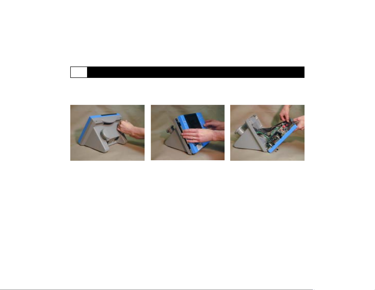
Disassembly, Service Part Installation and Re-assembly
5
Overview
This section gives a pictorial step by step instruction of disassembling, repairing, and re-assembling your neo2000®. Neoprobe
recommends that the servicing technician complete the Service Checklist prior to returning a neo2000 to operation (see Appendix C).
Step 1.
Remove 5 screws from the rear of the unit
with a No. 1 or No. 2 Phillips head
screwdriver. Gently pull off volume knob.
Step 2.
Gently separate the front and rear
housings. Be careful not to damage the
EMI fingers.
Step 3.
Disconnect the auxiliary cable to allow
separation of the front and rear assemblies.
5-1
Page 27
Disassembly, Service Part Installation and Re-assembly (continued)
5
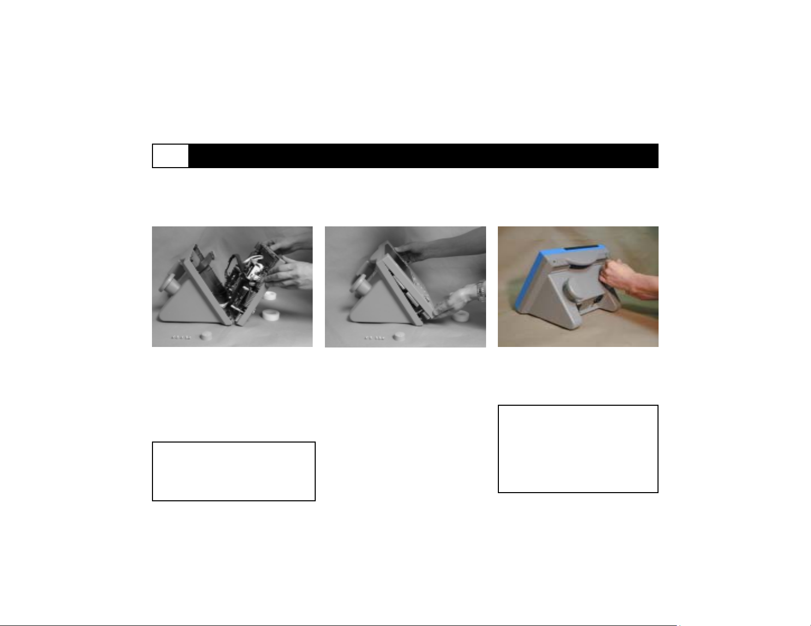
Step 4.
After disconnecting the auxiliary cable,
support the corners of the front housing to
avoid damage to the volume encoder.
Hint: Use two rolls of tape to support
front housing.
Caution: The volume encoder
may be damaged by mechanical
shock.
Step 5.
Using the service manual as a guide,
identify the problematic part which needs
replacement. Order a replacement part
using the Authorized neo2000® Parts list
(see appendix B).
Now that the part has been replaced,
gently reconnect the front housing to the
rear housing making sure that nothing
protrudes.
Step 6.
Holding the housings together, turn the
console to its rear. Reinstall the 5 Phillips
head screws which were initially removed.
Warning: The internal electronics
of the neo2000 are sensitive to
damage from electrostatic
discharge (ESD). Use appropriate
precaution when opening and
servicing the unit.
5-2
Page 28
Performance Verification
6
Overview
Neoprobe Corporation recommends servicing technicians complete the pre-closure checklists prior to completing the following performance verification checklist for the neo2000®. The performance verification checklist is necessary to determine proper operation of
the unit. If any problems observed in performance after servicing indicate that the unit is not working, it should be returned to
Neoprobe Corporation for evaluation. (See Appendix C for a complete service checklist.)
Operation
Power-Up unit
Verification Observation
Verify LEDs All LEDs lit
Plug in probe and cable No probe error disappears
(see Chapter 1.1 of the neo2000
Operation Manual)
Diagnostic test
(see Chapter 4.1 of the
neo2000 Operation Manual)
Electrical Safety Tests
Operational - Dynamic Pitch
Mode
VITM - top half display All indicators lit
VITM - bottom half display All indicators lit
ICTM - button press All buttons respond
per Institute procedure Complies with institute’s procedure
Select Dynamic Pitch/Tc-99m/1000cps Target Count display active
Position probe over Tc-99 or Co-57 source Verify display counts and audible response
to get 250cps - 1000cps
Activate Target Count over source (Tc-99 or Co-57) Verify response to source
6-1
Page 29
Performance Verification (continued)
6
Operational - Dynamic Mode
(Continued)
Repeat Target Count Verify consistent operation and resulting cps
Without moving source select Verify LED, display count, and audio over range
Dynamic Pitch/Tc-99m/100cps
Without moving source select Verify no response to source
Dynamic Pitch/I-131/100cps
6-2
Page 30
Disclaimers
7
Authorized Service
Representatives
Service of the Neoprobe neo2000
Gamma Detection System to the
extent described in this service
manual may be performed by authorized service representatives of
Neoprobe Corporation. Any unauthorized servicing operations
performed on the neo2000 shall
automatically void the warranty.
®
Service by Owners of the
neo2000
Neoprobe authorizes owners of the
neo2000 , and other independent entities
authorized by owners of the neo2000, to
service the neo2000 Gamma Detection
System to the extent described in this
manual. Service of the neo2000 by
owners or other entities may, at
Neoprobe’s sole discretion, void any
remaining warranty on the unit. Neoprobe
Corporation shall not be liable for any
claim for damages resulting from
servicing operations performed on
the neo2000 by owners or other
entities authorized by owners.
Parts
Replacement parts used in the repair of
the neo2000 must be obtained through
Neoprobe. Neoprobe can not ensure the
proper performance of the unit if any
replacement parts are obtained from any
other source. Use of any unauthorized
parts in the repair of a neo2000 shall
automatically void the warranty.
Neoprobe Corporation shall not be liable
for any claim for damages resulting from
the use of unauthorized parts in the
neo2000.
Safety
The neo2000 incorporates safety features
in the internal construction and wiring that
are necessary to maintain the required
electrical safety rating. Personnel
servicing the neo2000 must be
familiar with these safety features,
and must not compromise any of
these safety features. Use of any
unauthorized wiring or other compromise of the neo2000 safety features
shall automatically void the warranty.
Neoprobe Corporation shall not be liable
for any claim for damages resulting from
unauthorized wiring or other compromise
to the safety features of the neo2000.
Unauthorized Service
Neoprobe Corporation shall not be liable
for any claim for damages resulting from
unauthorized service of the neo2000.
This shall include attempts by any person
to perform modifications to the product’s
design such as, but not limited to,
rewiring, use of unauthorized parts, and
tampering, alteration or abuse of parts or
accessories such as cables, wire harnesses, probes, line filters, etc.
7-1
Page 31
Service Policy
8
Overview
This section describes how to obtain
warranty and out-of warranty service on
the neo2000® Gamma Detection System.
All service on the neo2000 must be
performed by an authorized service
representative of Neoprobe Corporation
(“the Company”).
Warning: Returned products must be
properly decontaminated in accordance
with all applicable regulations for
biohazardous material.
Warranty Service
To obtain service under your warranty, do
the following:
Obtain advance authorization prior to
returning any products to the Company.
Before returning any equipment, either
write or call Neoprobe Corporation at 800793-0079 or 614-793-7500.
Providethepart number and serial
number for the defective product (if
applicable), a technical description
of the defect or malfunction, a nocharge purchase order, and your
appropriate shipping and billing
addresses. At the same time, obtain
a returned merchandise authorization
(RMA) number from Neoprobe.
Return the entire neo2000 or other
product in its original packing. The
shipment must be clearly labeled with the
RMA number and prepared in accordance
with good commercial practices. Shipment
to the Company shall be at Buyer’s
expense. Repaired or replacement
equipment will be shipped by the Company
to the Buyer with shipping and insurance
costs paid for by the Company (C.I.P.).
Nonverified problems or defects are
subject to an evaluation charge.
Out-of-Warranty Service
To obtain out-of-warranty service,
do the following:
Obtain advance authorization and
estimate of the service cost prior to
returning the product to the Company. Before returning any equipment, either write or call Neoprobe
Corporation at
800-793-0079 or 614-793-7500. Provide
the part number and serial number for the
defective equipment (if applicable), a
technical description of the malfunction, a
purchase order number covering the
Company’s estimate of the repair cost,
and shipping and billing addresses for the
Buyer. At the same time, obtain a
returned merchandise authorization (RMA)
number.
Return the entire neo2000 or other
product in its original packing. The
shipment must be clearly labeled with the
RMA number and prepared in accordance
with good commercial practices. Shipment
to Company shall be at Buyer’s expense.
Repaired or replacement equipment will be
shipped by the Company to the Buyer with
shipping and insurance costs paid for by
the Company (C.I.P.). Nonverified
problems or defects are subject to an
evaluation charge.
8-1
Page 32
Warranty
9
Service Warranty. Service and service parts provided by Neoprobe Corporation (“the Company”) are warranted against defects in
workmanship and materials for a period of 90 days from the date of shipment by Company to Buyer, subject to the limitations
hereinafter set forth. Should any defects be found and reported during that period, Company, at its option, will repair or replace
such defective equipment provided that Buyer ship the product containing the defect to Company, transportation charges prepaid,
with notice of the defect and representation that the equipment has been properly installed, maintained, and operated within the
limits of rated and normal usage. The repaired or replacement equipment will be shipped C.I.P. (carriage and insurance paid) from
the Company’s plant.
This warranty shall not apply to any service parts where the installation or servicing of such service parts is improper, or where
service parts are operated above rated load capacity, or subjected to accident, tampering, alteration, or abuse. THE
COMPANY’S LIABILITY UNDER THIS WARRANTY OR ANY OTHER WARRANTY WHETHER EXPRESS OR IMPLIED IN LAW
OR FACT SHALL BE LIMITED TO THE REPAIR OR REPLACEMENT OF DEFECTIVE MATERIAL AND WORKMANSHIP, AND
IN NO EVENT SHALL THE COMPANY BE LIABLE FOR CONSEQUENTIAL OR INDIRECT DAMAGES.
THIS WARRANTY ALONG WITH ANY APPLICABLE PRODUCT WARRANTY(SEE OPERATION MANUAL) CONTAINS THE ENTIRE
OBLIGATION OF NEOPROBE CORPORATION AND NO OTHER WARRANTIES INCLUDING, WITHOUT LIMITATION, WARRANTIES
OF MERCHANTABILITY AND FITNESS FOR A PARTICULAR PURPOSE OR OTHER WARRANTIES EXPRESSED, IMPLIED, OR
STATUTORY ARE GIVEN.
9-1
Page 33
Notices10
This page intentionally left blank.
10-1
Page 34
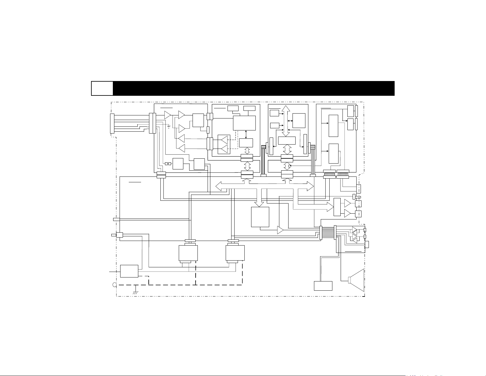
neo2000® Functional SchematicA.1
Probe Inpu t
Connect or
(See Figure A.1-3 )
Sw it ch
Pow e r
Pow e r
PDM B oard
J2
Main Board
Upper Wind ow
Comparat or
Low er Window
Comparat or
Upper
Windo w Th reshol d
Low er
Window Thr eshold
Bias
z
z
Supply
J1
J10
LED
J17
J2
+12v
Pow er
Supply
J1
Lin e
Fil t er
PE
Puls e
Det ect
Logi c
Supply
+ 12v
Probe
DSP Boa rd
Flas h
D S P
Dual Port
Memory
SRAM
PC104
PC104
J5
J3
J3
Analog I/O
J4
J4
J6, J7
J6, J7
J4, J6
J3
J20
CPU Boar d
Flash
DRAM
Seri al Port
Buff er
486
CPU
CPU BU S
PC104
J1, J2
PC104
J1, J2
J3, J5
PC 104 BUS
Sound
Gener at or
J21
J2
+5v
Pow e r
Supply
Audio
Amp
I/O Board
Digi t ial I /O
24 Channel s
J9
Seri al Por t
Digital I/O
24 Channels
J5
J19
J1
J18
J1
Cooling Fan
(+ 5 v DC)
(2)
Ser ia l Por t
(2)
Seri al Por t
J6
J2
Display
Driver s
Auxillary Board
Audio
Speaker
J3
J4
Input Switches
Volume Encoder
Numeric Display
LED Indicat ors
(x8 )
(x3)
(x17 )
Serial Port 2
RJ4 5
Serial Port 1
Input Switch
DB9
(x1)
Figure A.1-1. Model 2000 Configuration.
A.1-1
Page 35
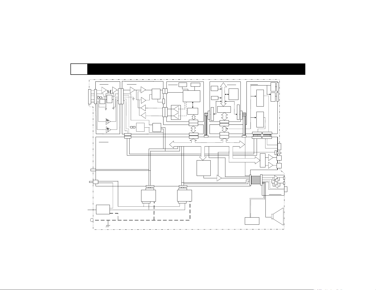
A.1 neo2000® Functional Schematic (continued)
Probe Input
Connect or
(See Figure A.1-4 )
Pow er
LED
Pow er
Sw it ch
PIM Boar d
J2
z
z
+ 12 V
PS
Bias
Main Board
Line
Fil t er
PE
PDM B oard
J1
J2
Upper Wind ow
Comparat or
Low er Window
z
z
Supply
J1
J10
Comparat or
Bias
Detect
Upper
Window Threshold
Low er
Window Thresh old
Pulse
Logic
+ 12v
Probe
Supply
DSP Boar d
Flas h
D S P
Dual Por t
Memory
SRAM
PC104
PC104
J6, J7
J6, J7
J4, J6
Fla sh
DRAM
J3
J20
J5
J3
J3
Analog I /O
J4
J4
CPU Bo ard
486
CPU
CPU BUS
Buffer
PC104
Ser ial Por t
J1, J2
PC104
J1, J2
J3, J5
PC 10 4 BUS
Sound
Generat or
J17
J2
+12v
Pow er
Supply
J1
J21
J2
+5v
Pow er
Supply
Audio
Amp
I/O Board
Digi t ial I /O
24 Channel s
J9
Ser ial Por t
Dig it al I/ O
24 Channel s
J5
J19
J18
J1
Cooling Fan
(+ 5v DC)
(2)
Serial Port
(2)
Serial Port
J6
J2J1
Disp lay
Drivers
Auxi llary B oard
Audio
Speaker
J3
J4
Input Switches
(x8)
Volume Encoder
Numeric Display
(x3)
LED Indicat ors
(x17)
Serial Por t 2
Serial Por t 1
RJ4 5
DB9
Input Switch
(x1)
Figure A.1-2. Model 2100 Configuration.
A.1-2
Page 36
A.1 neo2000® Functional Schematic (continued)
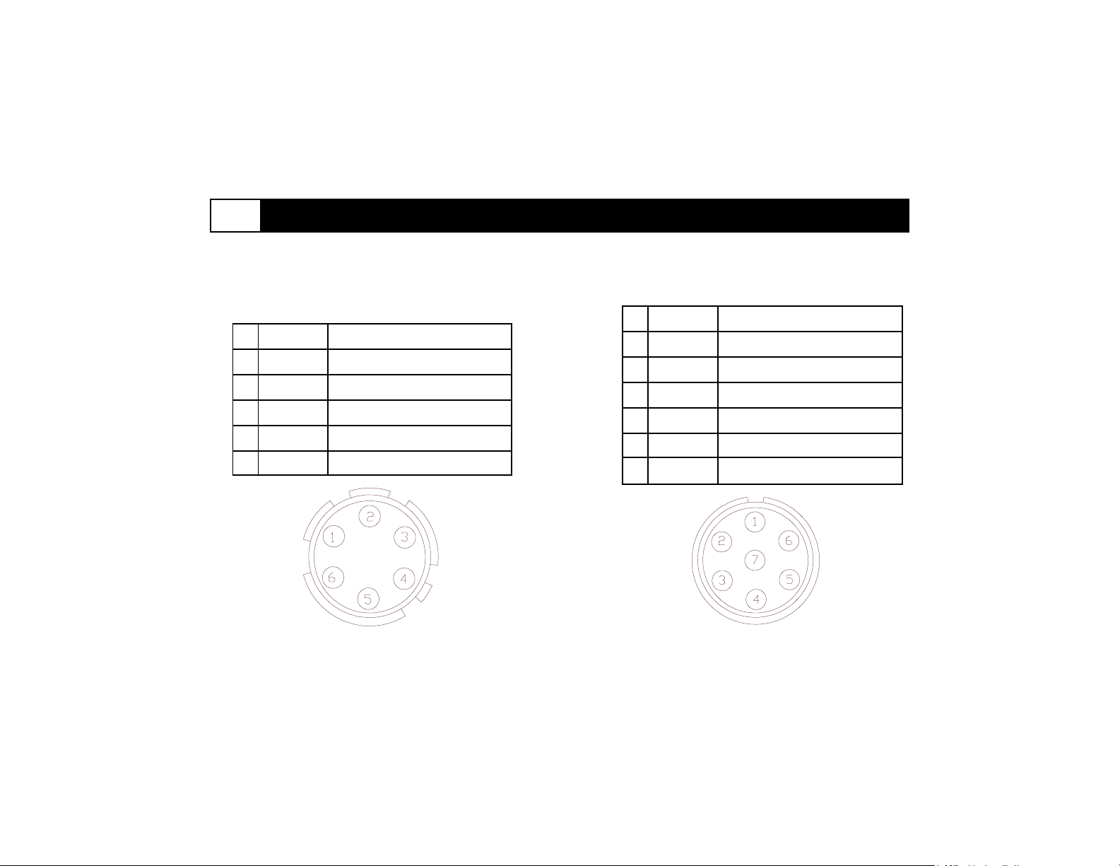
Probe Input Connector Pin Assignments
1 ISOCOM
1 COM
2 SIG Input Impedance 10kV-30kV
3 +12V 11.4v-12.6v
4 BIAS
5 CTL 1 5v
CTL 2
6
Figure A.1-3. Model 2000 (frontal view of unit) Figure A.1-4. Model 2100 (frontal view of unit)
Common
>50v
5v
2 CTL 2 12v
3 CTL 1 12v
4 BIAS
5 +12V 11.4v-12.6v
SIG
6
7 ISOGND Common
Input Impedance 10kV-30kV
Common
>50v
A.1-3
Page 37
A.2
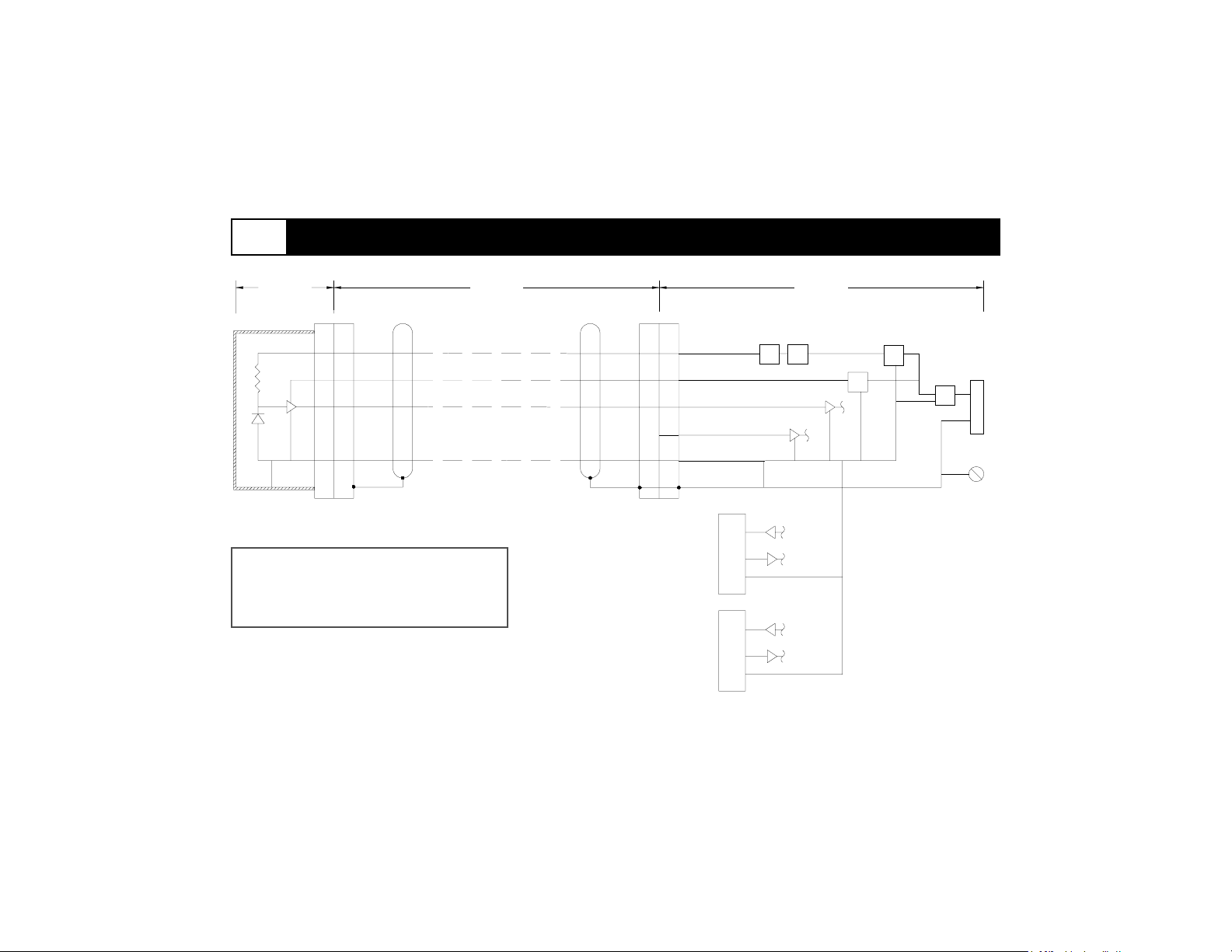
neo2000® Grounding & Isolation Diagram
Probe
(Model 1017)
Warning: Proper configuration of
grounding required for safety.
Figure A.2-1. Model 2000 Configuration.
Cable
(Model 202 1)
Bi as
+ 12V
Signal
Con t r ol 1/ 2
Co mmo n
PE
RS232
DB9
RS232
RJ 4 5
Z
Con t r ol Uni t
(Model 200 0)
Z
P/ S
P/ S
3 Pin IEC
Li ne Fil ter
P/ S
Ground
PE
A.2-1
Page 38
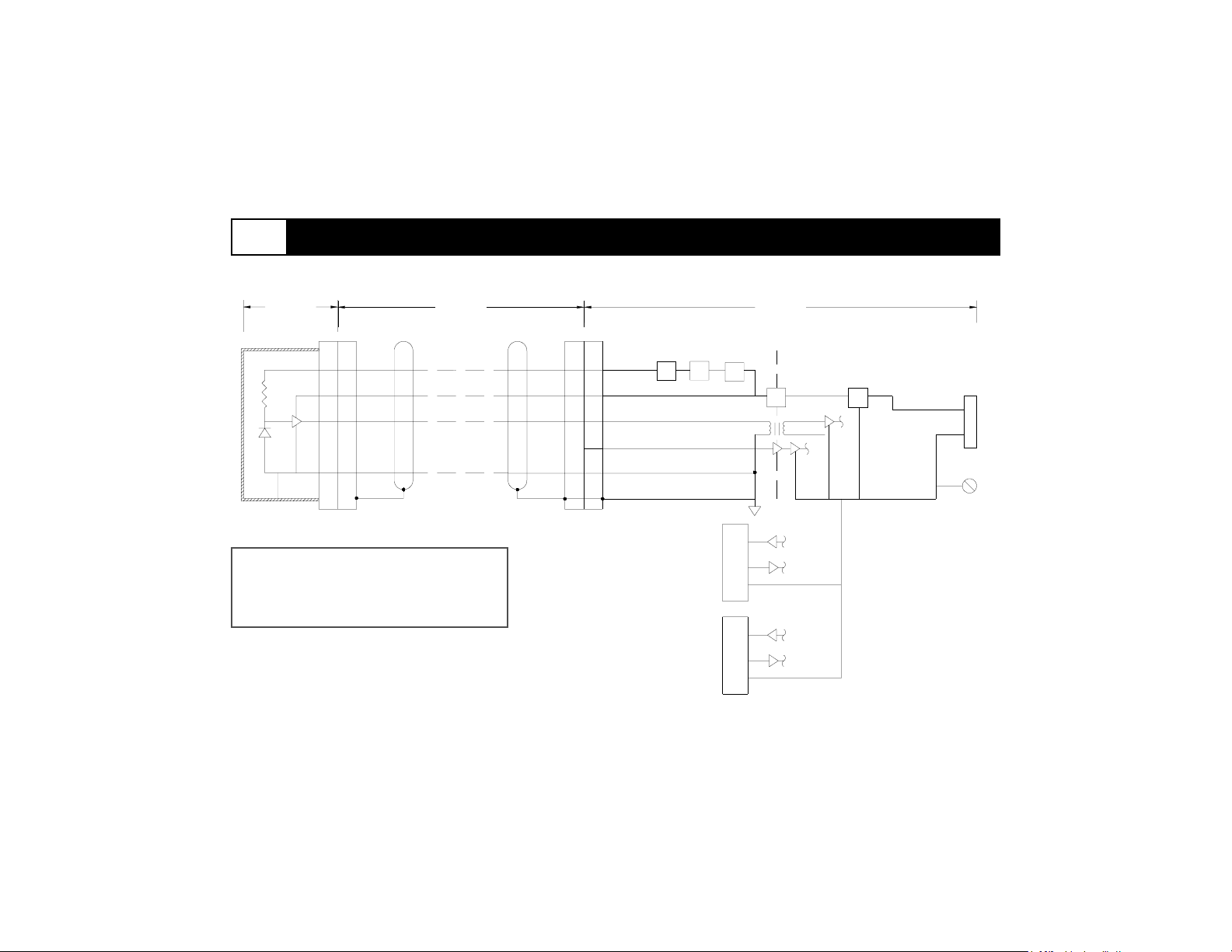
A.2 neo2000® Grounding & Isolation Diagram (continued)
Pr o b e
(Model 1017)
Cab l e
(Model 2024)
Warning: Proper configuration of
grounding required for safety.
Figure A.2-2. Model 2100 Configuration.
Bi as
+ 12V
Signal
Contr ol 1/2
Comm o n
ISO
ZZ
RS232
DB9
RS232
RJ 4 5
P/ S
Control Unit
(Model 2100)
Isolation
Bar ri er
P/ S
ISO
P/ S
3 Pin IEC
Line Filter
Ground
PE
A.2-2
Page 39
A.3
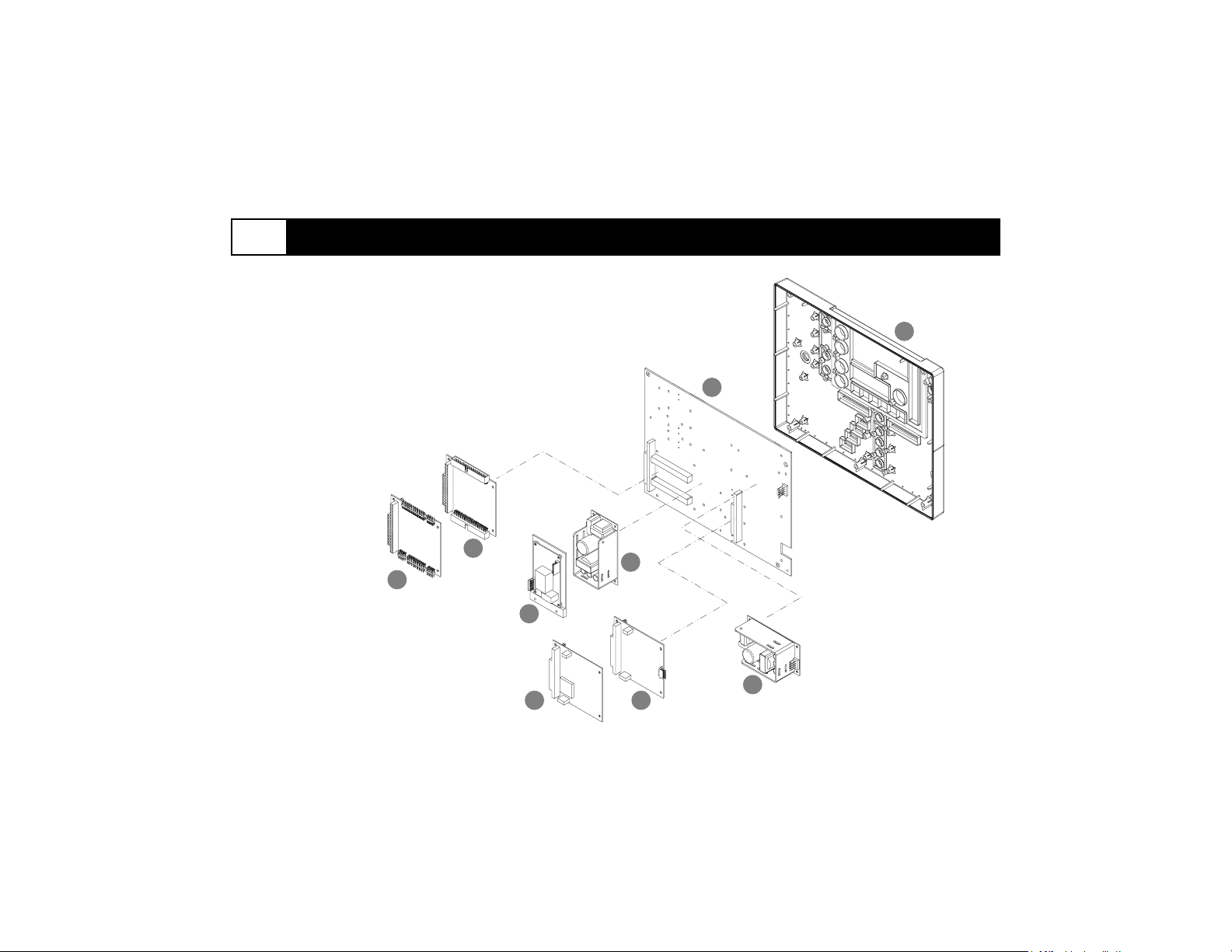
1. Front Housing
2. Main Board
3. I/O Board
4. CPU Board
5. 5V Converter
6. PIM Board (Model 2100 only)
7. PDM Board
8. DSP Board
9. 12V Converter
Front Housing Assembly
1
2
Figure A.3-1. Exploded view.
3
5
4
6
9
8 7
A.3-1
Page 40
A.3 Front Housing Assembly (continued)
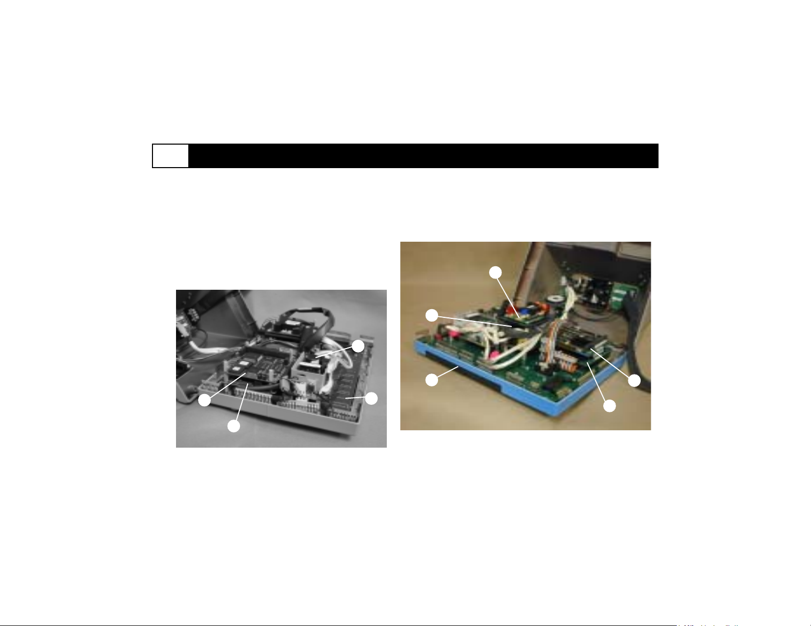
1. Front Housing
2. Main Board
3. I/O Board
4. CPU Board
5. 5V Converter (positioned under PIM Board)
6. PIM Board (Model 2100 only)
7. PDM Board
8. DSP Board
9. 12V Converter
9
6
5
8
7
Left Side View (Model 2100)
Figure A.3-2. Assembled view.
1
2
Right Side View (Model 2100)
4
3
A.3-2
Page 41
A.4
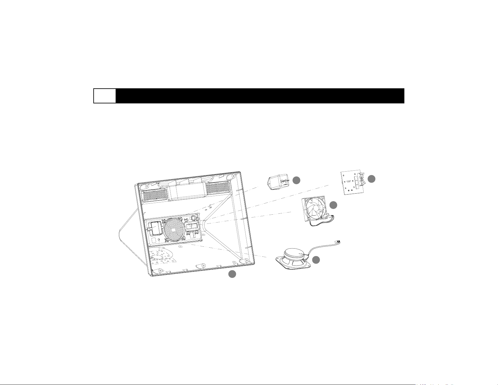
1. Rear Housing
2. Line Filter
3. Auxiliary Board
4. Fan
5. Speaker
Rear Housing Assembly
Figure A.4-1. Exploded view.
2
4
5
1
3
A.4-1
Page 42
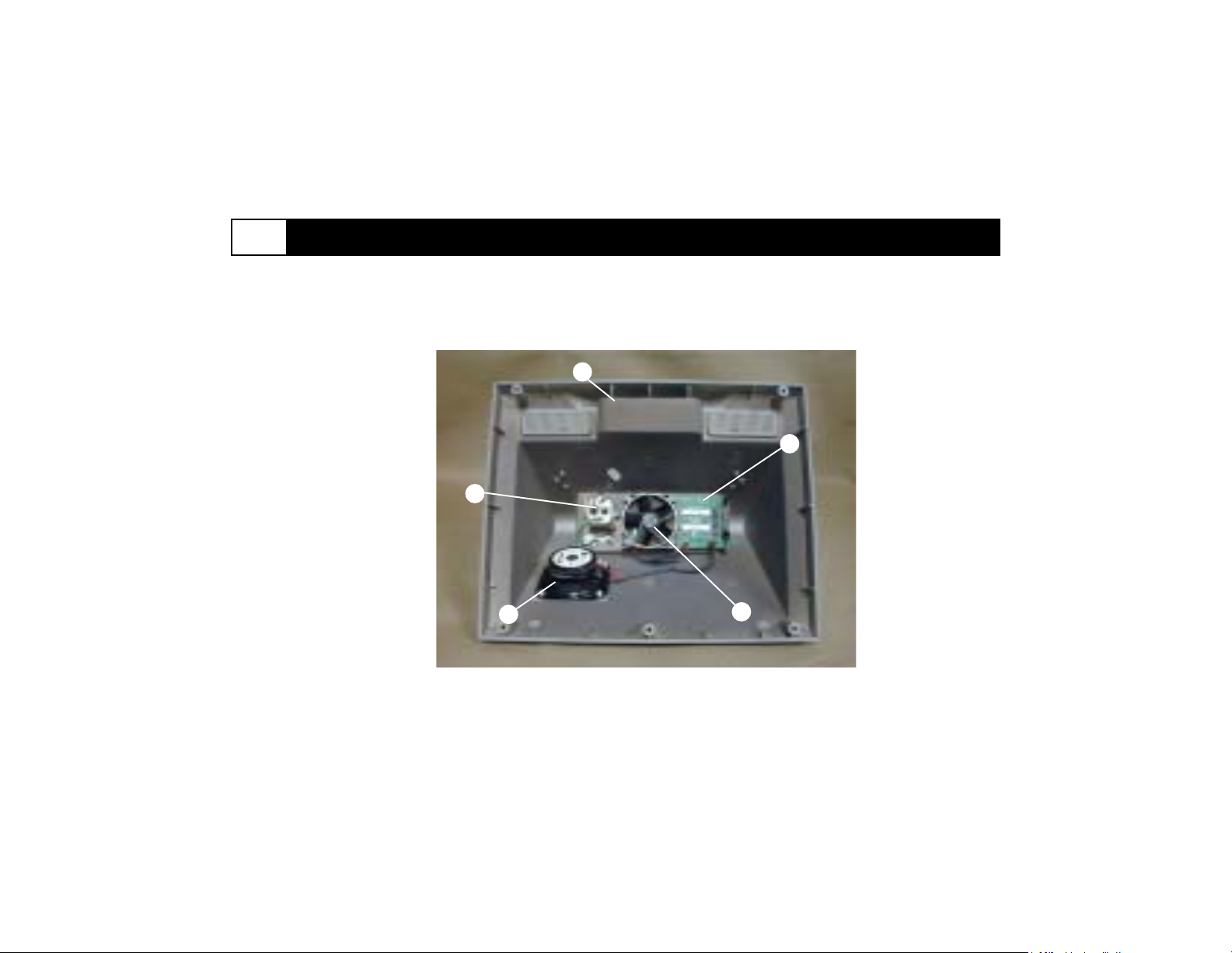
A.4 Rear Housing Assembly (continued)
1. Rear Housing
2. Line Filter
3. Auxiliary Board
4. Fan
5. Speaker
1
2
3
Figure A.4-2. Assembled view.
5
4
A.4-2
Page 43
B Neoprobe Authorized Service Parts
To order Neoprobe Authorized Service Parts contact Neoprobe Technical Support at 800-793-0079 or 614-793-
7500. Please make sure to identify your neo2000® Model Number and Serial Number and the service parts that
you require. Below is a categorized checklist for your convenience when placing an order.
neo2000 Model Number: Model 2000
Model 2100
BOARDS
P100Main Board
P101* CPU Board (V1.03)
P108 CPU Board (V2.01)
P102* DSP Board (V1.03)
P109 DSP Board (V2.01)
P103 PDM Board (2000)
P104 PDM Board (2100)
P105 I/O Board
P106 Auxiliary Board
P107 PIM Board (2100)
KITS
P145 Labeling Kit (2000)
P146 Labeling Kit (2100)
P120 CPU1 Cable
P121 CPU2 Cable
P122 I/O Cable
P123 PIM to PDM Cable (2100)
P124 Line Filter Cable
P125 Line Filter Ground Cable
P126 Power Converter Cable
P127 Power Converter Ground Cable
P128 Probe Input Cable (2000)
P129 Probe Input Cable (2100)
P130 Probe Input Ground Cable
P131 Speaker Cable
P132 Auxiliary Board Cable Assembly
neo2000 Serial Number
Software Version
CABLES
* Indicate software version required or contact Neoprobe.
POWER SUPPLY
P140 12V Power Supply
P141 5V Power Supply
OTHER
P150 Cooling Fan Assembly
P151 Fuses (2)
P152 Speaker
P153 Fluid Ingress Gasket
P154 Front Housing Shell (2000)
P155 Front Housing Shell (2100)
P156 Rear Housing Shell
P157 Power Switch
P158 Line Filter
P159 Volume Encoder
B-1
Page 44
C neo2000® Service Checklist
Neoprobe recommends that servicing technicians complete the following checklist prior to returning a neo2000 to
operation. The completed form should be retained in your files for tracking service history.
Pre-closure Checklist
Electrical Safety (See chapter 3) EMC Compliance (See chapter 3)
Green Yellow wires securely fastened EMI fingers securely fastened and not broken
Over insulation on all wiring No wires or EMI fingers protruding
All connectors fully mated
Fluid ingress gasket properly installed in housing joint
No conductive items protruding from openings in the
device (e.g. housing joint, speaker or fan vent)
Post-closure Checklist
Performance Verification (See chapter 6)
Power up unit Operational - Dynamic Mode
All LEDs lit Target count display active
Plug in probe and cable Verify display counts and audible response
No probe error disappears Verify response to source
Diagnostic test Verify consistent operation and resulting cps (4 times)
All indicators lit Verify LED, display count, and audio over range
All buttons respond
Electrical Safety Tests (per institute procedure)
All indicators lit
Verify no response to source
Parts replaced:
C-1
 Loading...