

Page 1

BLAST FREEZER
BLAST CHILLER
ISTRUZIONI D’USO E MANUTENZIONE
ISTRUCTIONS FOR THE USE AND MAINTENCE
ISTRUCTIONS POUR L’UTILISATION ET LA MAINTENANCE
Page 2

34
INDEX
INTRODUCTION 35
REGULAR MAINTENANCE 36
EXTRAORDINARY MAINTENANCE 37
INSTALLATION INSTRUCTIONS 38
INSTALLATION 39
RECOMMENDATIONS FOR CORRECT USE 40
INFORMATION FOR A CORRECT WASTE 44
ELECTRONIC CONTROLLER WORKING 45
Page 3

35
INTRODUCTION
The manifacturer would like to thank you for having chosen its products and we are
sure that you will be more than satisfied with their performance.
To help maintain efficiency and performance in time, we have prepared this manual
that describes the correct use and maintenance of the Blast Chiller Freezer.
TYPE OF USE AND LIMITATIONS
This Blast Chiller Freezer has been designed for chilling and preserving food (it
rapidly lowers the temperature of cooked food in this way preserving quality and
guaranteeing freshness for several days). Any other use is considered improper and
incorrect.
This Chiller cannot be installed outside and or in environments subject to weather
conditions.
The manufacturer declines all responsibility for uses other than those given in this
manual.
TESTING
The Chiller is dispatched only after it has been tested (visual inspection – electric test
– functional test). Final testing is certified, for the relevant documentation please
refer to the enclosed appendixes.
GENERAL SAFETY STANDARDS
The Chiller in question is manufactured conforming with the European Directives
relevant to low tension 73/23-93/68/EEC, and electromagnetic compatibility
89/336/EEC; EN60335- 1, EN60335-2-24, EN55014, EN61000-3-2, EN61000-3-3,
EN55104.
WHAT THE CUSTOMER MUST PROVIDE ON SITE LOCATION
It is necessary that there is an earthed power socket suitable for the electrical input
indicated on the metal plate, a thermomagnetic switch with at least a 3 mm break
contact.
CAUTION:
The Blast Chiller must be powered by a single phase power supply
(230 V – 50 Hz). Make sure it is level and always use qualified personnel to install,
repair and service your Chiller.
Page 4

36
TECHNICAL ASSISTANCE
Thanks to the network of concessionaires and authorised service centres, the
manufacturer guarantees its customers an after-sales service.
REGULAR MAINTENANCE
WARNINGS
Regular maintenance work can be carried out by non-specialised personnel who,
however, must always adhere to the instructions given in this manual. Before
cleaning or servicing the chiller lock-off the power supply. When carrying out
regular maintenance work do not remove any of the safety guards.
CLEANING THE CHILLER AND ACCESSORIES
Before using this Chiller clean on the inside and all the accessories. Use warm water
and neutral soap. Rinse and dry well. Do not use solvent or powder based detergents
and use a silicon wax to protect the steel.
PERIODICALLY CLEANING THE CONDENSER
The condenser should be cleaned periodically. Cleaning intervals will depend on
how frequently it is used.
CAUTION
: To access the condenser (please refer to page 16 in the spare parts
catalogue) it is necessary to remove the safety guards. Always use qualified and
specialised personnel.
To guarantee efficiency and performance in time, it is necessary to clean the
condenser periodically. It is highly recommended if located in dusty environments to
clean the louvers on the refrigerating unit once a month and once every three months
if located in closed and clean environments. To remove dust and dirt from the
louvers use a brush or vacuum cleaner. Do not use sharp objects or tools that could
damage the condenser. Do not clean using water jets.
MEASURES TO TAKE WHEN OUT OF SERVICE FOR A PERIOD OF TIME
Page 5

37
When the Chiller is out of service for a long period of time take the following
measures:
- Remove the plug from the power socket;
- Remove all food and clean the inside of the Chiller and all accessories;
- Buff all the stainless steel surfaces with a cloth moistened with vaseline oil
to give a protective coating;
- Leave the door ajar for air circulation to prevent bad odours;
- Periodically air the room or kitchen where the Chiller is installed.
EXTRAORDINARY MAINTENANCE
CAUTION: Extraordinary maintenance and servicing work must be carried out be
qualified personnel!
UNDERSTANDING SIMPLE MALFUNCTIONS
At times malfunctions are due to simple and trivial causes and nearly always there is
no need to call in a specialised technician, therefore before informing the company
check for the following:
The Chiller is not powered:
c. Check that it is plugged in;
d. Check that there is power.
The Chiller does not reach the correct internal temperature:
c. Check the temperature settings;
d. Check the probe.
The Chiller is excessively noisy:
c. Check that the Chiller is level. If unbalanced this could cause vibrations
creating excessive noise.
d. Check that the Chiller is not positioned up against other machines or objects
causing vibrations.
After having proceeded with the foregoing checks and if the problem persists,
contact the company giving:
- A description of the type of malfunction;
- Chiller code and serial number which are indicated on the metal plate.
Page 6

38
WASTE DISPOSAL AND SCRAPPING
Storing waste:
It is possible to temporarily store special waste products that are to be scrapped.
However, the user must observe and adhere to the local governing laws regarding
waste management.
Macro – dismantling the Chiller:
Each country has its own waste management laws, therefore the user must observe
and adhere to the local governing laws where the Chiller is to be scrapped.
As a general guideline the Chiller should be handed over to a special waste treatment
plant. Dismantle it and divide the various components into groups according to their
chemical properties. Remember that there is oil and refrigerating solutions in the
condenser that can be recuperated and reused and the various components are
considered special waste products and as such are treated as urban waste.
CAUTION
: All dismantling operations must be carried out by specialised
personnel!
INSTALLATION INSTRUCTIONS
INTRODUCTION
This manual aims at providing the user with all the necessary information to
correctly use and maintain the Chiller.
Before use carefully read all the instructions given in this manual.
The manufacturer shall decline all responsibility for operations and use which
disregard the instructions herein.
MATERIALS AND CHILLING SOLUTIONS
All the surfaces that come in contact with food are in stainless steel.
This Chiller has an HFC chilling solution which is consented by current law. The
type and quality of the gas is indicated on the metal plate.
ELEMENTARY SAFETY STANDARDS – RISKS
Page 7

39
The Chiller has no dangerous corners, sharp and cutting surfaces or protruding parts.
All safety guards on moving parts or electrics are screwed to the cabinet. These
guards avoid any form of accidental contact with parts that present a risk to the user.
Always respect safety standards:
- Do not touch the Chiller with wet hands or feet;
- Not use the Chiller barefooted;
- Do not poke screwdrivers, cutlery or other objects between the safety
guards mounted on moving parts;
- Before cleaning or servicing the Chiller lock-off the power supply.
INSTALLATION
Carefully follow and adhere to the instructions given in this chapter to guarantee
working efficiency and safety when the Chiller is in use.
CAUTION
: When transporting or moving the Chiller to the installation site do not
push or drag it, lift it and position it on a trolley to avoid overturning.
LOCATION
Locate the Chiller in a ventilated area distant from heat sources such as radiators, air
conditioning units, deep-fryers and ovens.
Make sure the Chiller is located at a distance not less than 10 cm from the back wall
to permit a good cooling effect for the various components.
To maintain the correct internal temperature, the ambient temperature must not
exceed +32°C
Adjust height and levelling using the support feet and also check the door closes. If
the Chiller is not perfectly level working efficiency and condensation flow may be
affected.
Remove the PVC protective film on both sides of the Chiller.
CONNECTING TO THE POWER SUPPLY
The Blast Chiller works off single-phase tension 230V- 50Hz.
To connect to the power supply, simply plug the power cable in the power socket or
connect the Chiller to the electrical panel, however before connecting check that:
Page 8

40
- The socket is earthed and frequency and tension correspond to the
information given on the metal plate. If in doubt about earthing, call in a
qualified electrician to check wiring.
- A suitable thermomagnetic switch must be provided between the power
cable and electricity line with at least a 3 mm break contact.
- when the Chiller is connected to the mains check that the supply tension,
with the Chiller working, does not exceed or go under the rated tension by
+/- 10%.
CAUTION
: the manufacturer shall not be held responsible for damage or accidents
caused by negligence due to the non-observance of the recommendations and
regulations given or of the local governing standards and laws regarding electrical
safety.
RECOMMENDATIONS FOR CORRECT USE
Before using the Chiller remove all traces of glue using a detergent as there might be
traces of condensate due to final testing in the factory.
Chiller efficiency when chilling and freezing depends on the following factors:
Type of containers to use:
We recommend you use pans (or containers with sides no greater than 65 mm in
height) to permit an effective air circulation (the food product should be exposed to
the air circulation as much as possible to reduce chilling times ). To avoid the food
being contaminated, we recommend you carefully clean all containers and trays. We
also recommend you keep the food in the same cooking pan when chilling.
Using covers:
Do not cover the food when chilling or freezing. Only once the chilling and freezing
cycles have been completed or before storage can you cover or pack the food.
Page 9

41
CYCLES
BLAST CHILLING
The blast chilling cycle rapidly lowers the temperature of the food to a minimum of
+3 °C.
Blast chilling is for food that will be consumed within a few days.
BLAST FREEZING
Blast freezing is for storing food for longer periods of time. When blast freezing the
water content in the food is micro crystallized so when defrosting the food is not
altered in any way maintaining both its appearance and nutritional value. When
freezing the food core temperature reaches –18°C.
STORAGE
The Chiller has a storage cycle, in other words it maintains a set temperature, which
is automatically activated when the chilling or freezing cycles have been completed.
This storage is continuous and to stop the program simply press the (ON-OFF)
button.
Due to Chiller consumption, we recommend that you do not use this Chiller for
storing food for a long period of time. We suggest you store the food in fridges or
freezers.
Page 10
42
INFORMATION FOR A CORRECT WASTE
Directive on the electrical appliances waste (WEEE) (RoHS)
In the optical of the respect of the ambient of the health and based
on the sanctioned dispositions from the Directive 2002/95/CE of
the European Union in matter of limitation to the use of dangerous
substances (RoHS), regarding:
- LEAD ( Pb )
- MERCURY ( Hg )
- HEXAVALENT CHROMIUM ( Cr VI )
- CADMIUM (Cd )
- POLYBROMINATED BIPHENYL (PBB)
- POLYBROMINATED DIPHENYL ETHER (PBDE)
and according to of art. the 13, D.Lgs. 25 July 2005, n. 151 “Performance of the
Directives 2002/95/CE, 2002/96/CE and 2003/108/CE, relative to the reduction of
the use of dangerous substances in the equipment electronic electrical workers and,
to the waste disposition, the manufacturer declares that its products respect such
norms.
The following symbol on the side of the equipment indicates that
the product must not be disposed of as urban waste. Disposing of a
household appliance separately avoids possible negative consequences
for the environment and health deriving from inappropriate disposal
and enables the constituent materials to be recovered to obtain
significant savings in energy and resources. As a reminder of the need
to dispose of household appliances separately, the products is marked
with a crossed-out wheeled dustbin.
For information on the points of collection of the wasted equipment, contact the
residence borough, the local waste service or just the retailer in the case of purchase
a new equipment.
The illicit waste of the product from part of the customer involves the application of
the administrative endorsements of which article 50 and following of the D.Lgs n.
22/1997.
Page 11
43
ELECTRONIC CONTROLLER WORKING
1.1 Important
Carefully read these instructions before installation and use. Carefully adhere to all
warnings provided concerning installation, wiring and connection to the mains
electrical supply.
1.2 Installation
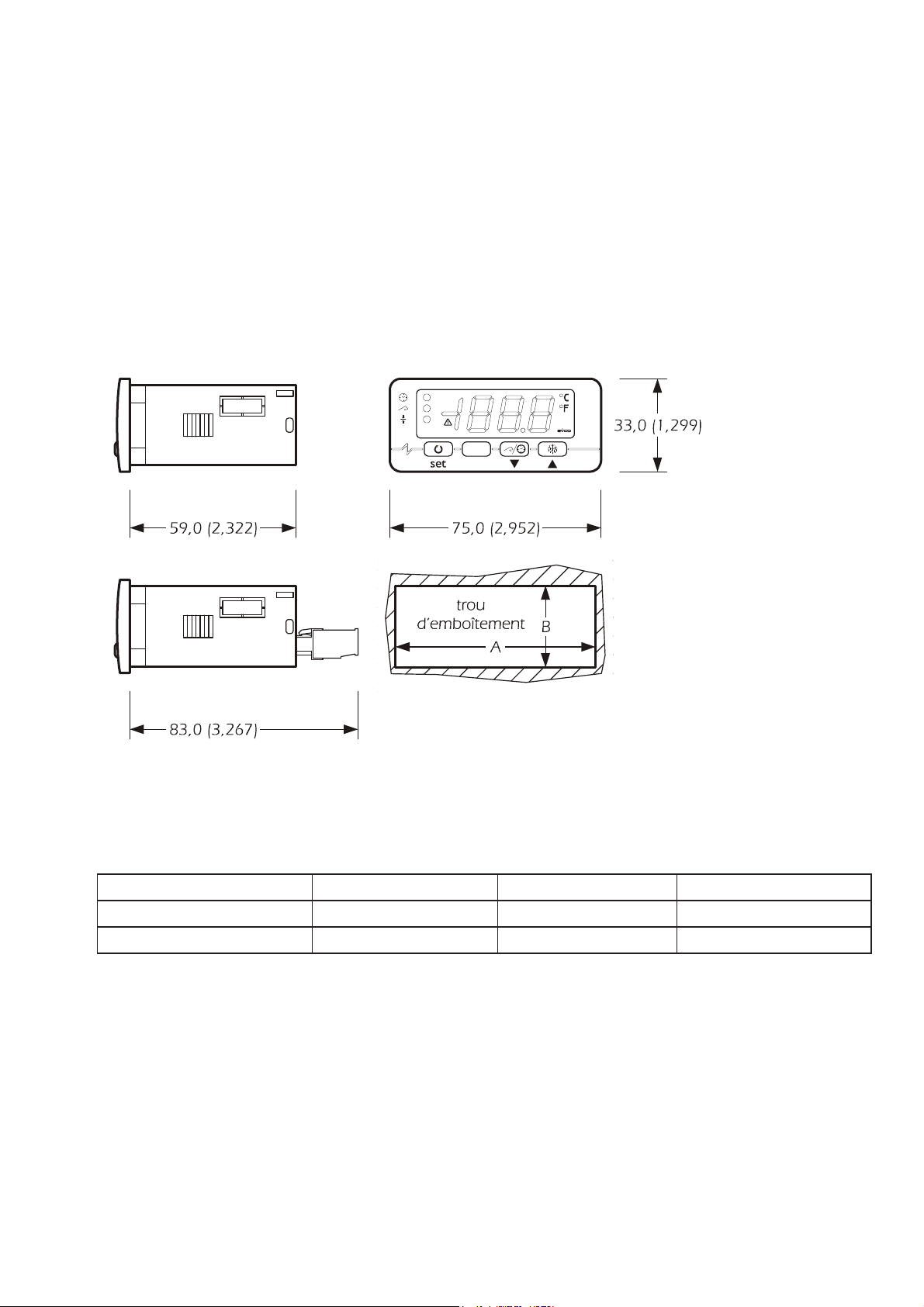
Panel with snap-on brackets provided; measurements in mm; measurements in mm.
The maximum depth is 89.5 mm whatever the type of connection and refers to
models with Faston connections (straight female Faston correctly inserted).
MEASUREMENT MINIMUM STANDARD MAXIMUM
A 71.0 71.0 71.0
B 29.0 29.0 29.8
Warnings when installing:
• 59.0 is the maximum depth with screw terminals
• 83.0 is the maximum depth with pull-out terminals
• panel thickness must not exceed 8.0 mm
• check that all work conditions (working temperature, humidity etc) are
within the limits provided in the technical specifications.
• do not install this system in proximity of heat sources (heating elements,
hot air outlets etc), equipment with powerful magnets (industrial and large sized
Page 12
44
diffusers etc), direct sunlight, rain, humidity, excessive dust, mechanical vibrations
and jolts.
• in conformity with the safety standards in force the protection provided to
prevent contact with the electrical parts is guaranteed by installing the system
correctly. All protective parts must be mounted and secured in place so that they
cannot be removed without the aid of a tool.
1.3 WIRING AND ELECTRICAL CONNECTION
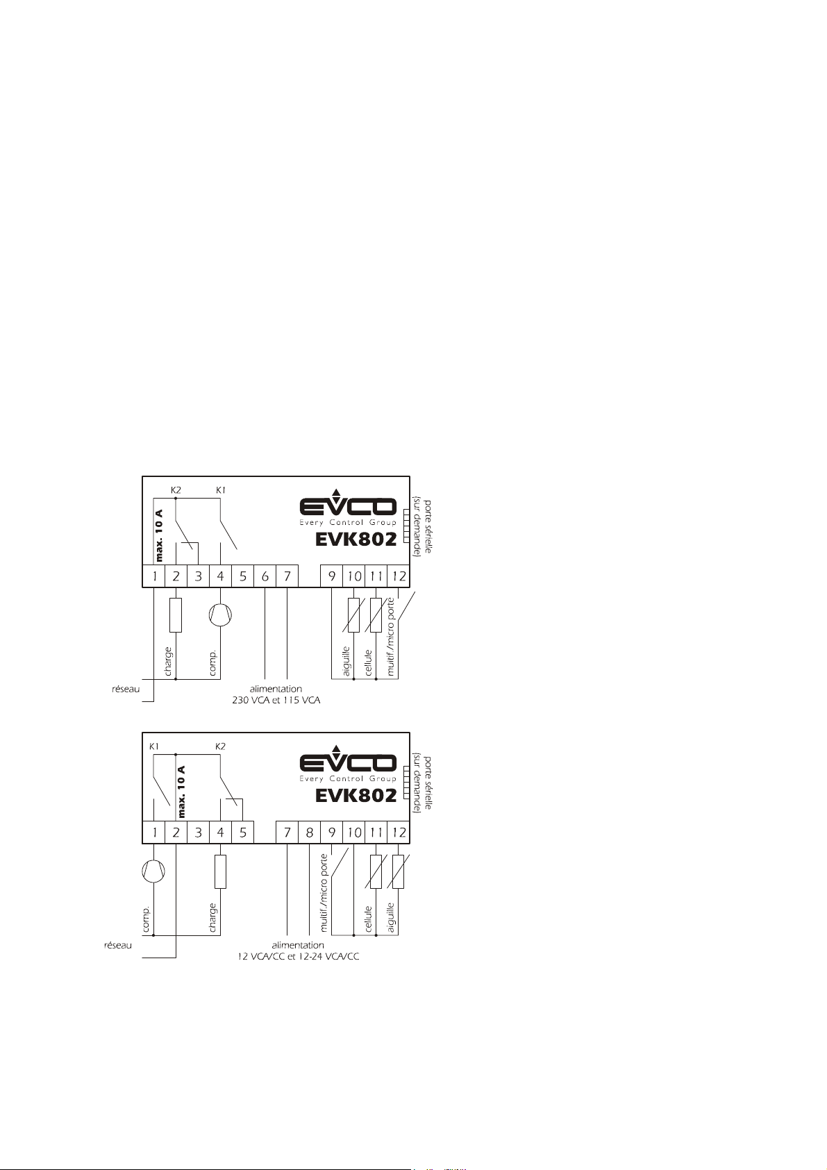
Referring to the wiring diagram:
• the function managed by relay K2 is subject to parameter u0
• the serial port (upon request) is the communication port with the monitoring
system (serial interface, via TTL - transistor – transistor logic - with a MODBUS
communication protocol) or with the programming key; the port must not be used
simultaneously for both purposes.
Warnings when wiring and connecting to mains supply:
• do not use electrical or compressed air driven screw drivers for the
terminals
Page 13

45
• if this system is moved from a cold location to a warmer location,
condensation may form on the inside; wait for approximately an hour before
powering.
• check system supply voltage, frequency and wattage correspond to the
mains electrical supply
• always disconnect the system from the power supply before proceeding
with any type of maintenance and or repair work
• do not use this system as a safety device
• for repairs and information concerning this system refer to your local sales
outlet
2 USER INTERFACE
2.1 Preliminary instructions
There are two working modes:
• “on” (the system is powered and a cycle is running )
• “stand-by” (the system is powered but a cycle is not running )
• “off” (the system is not powered)
If the power supply is unexpectedly interrupted during a timer controlled chilling
cycle, the moment power is restored the chilling cycle continues from the moment it
stopped (maximum error margin 10 minutes).
If the power supply is unexpectedly interrupted during a temperature controlled
chilling cycle, when power is restored the cycle restarts from the beginning of cycle.
If the power supply is unexpectedly interrupted during storage, when power is
restored storage mode continues.
If the power supply is interrupted with the blast chiller in stand-by mode
, when power is restored the chiller returns to stand-by.
2.2 Display
When “on” and during normal functioning, the following information is displayed:
• remaining cycle time for timer controlled blast chilling if blast chilling
• the temperature detected by the needle probe if running a blast chilling
cycle
• chiller temperature when running a storage cycle.
With the chiller in “stand-by” during regular functioning, the internal chiller
temperature is displayed for ½ a second every 3 seconds.
2.3 Defrosting and evaporator fan
The function managed by relay K2 is subject to parameter u0
• if u0=0 the function managed by relay K2 is defrosting (electrical
defrosting; the evaporator fan is not managed)
• if u0=1 the function managed by relay K2 is the evaporator fan (defrosting
with compressor off)
Page 14
46
- when blast chilling the evaporator fan is managed by parameter F0
- for storage the evaporator fan is managed by parameter F2
- when defrosting the evaporator fan is turned on.
With the chiller in stand-by only manual defrosting is possible; if the function
managed by relay K2 is the evaporator fan (parameter u0=1) the evaporator fan is
turned on and when dewatering this fan is turned off.
For manual defrosting:
• check that no other cycle is running
• press
for 4 seconds
When blast chilling deforesting is never activated.
When running a storage cycle defrosting is activated at set intervals; is possible to
activated defrosting in manual mode.
2.4 Compressor and evaporator fan conditions
To display information concerning the compressor:
check that no other cycle is running
• press
: the first available tag is displayed:
if “C-1” is displayed, the compressor is on
if “C-0” is displayed, the compressor is off
- if “C-P” is displayed, compressor protection is running (parameters C0, C1, C2 and
i7).
To display information concerning evaporator fan:
check that no other cycle is running
• press
twice: the first available tag is displayed:
if “F-1” is displayed, the evaporator fan is on
if “F-0” is displayed, the evaporator fan is off
if “F-P” is displayed, fan start up is delayed (parameter F8).
To escape this procedure:
• press
until the current chiller mode is displayed (refer to paragraph 2.2), or do
not use for 15 seconds.
If the function managed by relay K2 is defrosting (parameter
u0 = 0), tags “F-1”, “F-0” and “F-P” are not displayed.
3 CYCLES
3.1 Preliminary instructions
Chiller cycles are:
positive temperature timer controlled chilling and storage
negative temperature timer controlled chilling and storage
positive temperature with temperature controlled chilling and storage
negative temperature with temperature controlled chilling and storage
Page 15
47
Before running a temperature controlled chilling cycle a test is run to check that the
needle probe has been inserted correctly (refer to paragraph 3.6).
To restart utilising the same settings as the last cycle run:
make sure the system is in “stand-by” mode and that no procedure is running and
that another cycle has not be selected
• press
for 2 seconds: the last tag for the last cycle run is displayed
• press
within 60 seconds: cycle time is displayed if running timer controlled
chilling cycle (unit of measurement is in minutes) or chilling temperature to reach if
running a temperature controlled chilling cycle
• press
or within 15 seconds to modify value setting (setting remains active
until another cycle is selected or when the value defined by parameters
r1, r2, r3 or r4 is restored)
• press
within 15 seconds: cycle will start running.
3.2 Positive temperature timer controlled chilling and storage
To start the cycle:
check that the system is in “stand-by” mode and no other procedure is running
• press
to select “PoS” check that the LED is flashing
• press
within 60 seconds: blast chilling time will be displayed (the unit of
measurement is in minutes)
• press
or within 15 seconds to modify value setting (setting remains active
until another cycle is selected or when the value defined by parameters
r1)
• press
within 15 seconds: cycle will start running.
During blast chilling:
remaining chilling time is displayed
• LED
is on
parameter r1 defines chilling time
parameter r7 defines working setpoint
• press
several times:
- “PoS” is dipalyed
- displays chiller internal temperature
- escape this procedure or do not use for 15 seconds
After chilling time has been reached:
• the chiller goes into storage mode
• “End” is displayed
• a buzzer is activated and buzzer time is defined by parameter AA
• press a key to turn off the buzzer; press the key again to delete the prompt
“End”.
During storage:
Page 16

48
chiller internal temperature is displayed
• LED
and are on
parameter r9 defines working setpoint
• press
several times:
“PoS” is displayed
- escape this procedure or do not use for 15 seconds
To suspend the cycle:
• press
for 2 seconds:
3.3 Negative temperature timer controlled chilling and storage
To start the cycle:
check that the system is in “stand-by” mode and no other procedure is running
• press
to select “nEg” check that the LED is flashing
• press
within 60 seconds: blast chilling time will be displayed (the unit of
measurement is in minutes)
• press
or within 15 seconds to modify value setting (setting remains active
until another cycle is selected or when the value defined by parameter
r2 is restored)
• press within 15 seconds: cycle will start running.
If negative temperature blast chilling and storage cycles are not enabled (parameter
rb = 0) tag “nEg” is not displayed.
During blast chilling:
remaining chilling time is displayed
• LED is on
parameter r2 defines chilling time
parameter r8 defines working setpoint
• press
several times:
- “nEg” is displayed
- displays chiller internal temperature
- escape this procedure or do not use for 15 seconds
After chilling time has been reached:
• the chiller goes into storage mode
• “End” is displayed
• a buzzer is activated and buzzer time is defined by parameter AA
press a key to turn off the buzzer; press the key again to delete the prompt “End”.
During storage:
chiller internal temperature is displayed
• LED
and are on
parameter rA defines working setpoint
• press
several times:
Page 17
49
“nEg” is displayed
- escape this procedure or do not use for 15 seconds
To suspend the cycle:
• press for 2 seconds:
3.4 Positive temperature with temperature controlled chilling and storage
To start the cycle:
check that the system is in “stand-by” mode and no other procedure is running
• press
to select “PoS” check that the LED is flashing
• press
within 60 seconds: end of chilling temperature is displayed
• press
or within 15 seconds to modify value setting (setting remains active
until another cycle is selected or when the value defined by parameters
r3)
• press
within 15 seconds: cycle will start running.
Before running a cycle:
a test is run to check that the needle probe is inserted correctly (refer to paragraph
3.6)
- if the test is Ok the cycle is started
- if the test is negative the cycle is delayed
During blast chilling:
needle probe temperature reading is displayed
• LED
is on
parameter r3 defines end of chilling temperature
parameter r5 defines maximum chilling time
parameter r7 defines working setpoint
• press
several times:
- remaining chilling time is displayed
- “PoS” is displayed
- displays chiller internal temperature which flashes
- escape this procedure or do not use for 15 seconds
If the temperature detected by the needle probe reaches end of chilling temperature
before maximum chilling time has been reached:
the chiller goes into storage mode
“End” is displayed
a buzzer is activated and buzzer time is defined by parameter AA
press a key to turn off the buzzer; press the key again to delete the prompt “End”.
If the temperature detected by the needle probe has not reached end of chilling
temperature before maximum chilling time has been reached:
blast chilling will continue
• LED
flashes and LED remains on
the buzzer is activated
Page 18
50
• press
several times:
- to turn off the buzzer
- the extra chilling time elapsed over the maximum blast chilling time is displayed
- displays chiller internal temperature
- “PoS” is displayed
- escape this procedure or do not use for 15 seconds
when the temperature reading detected by the needle probe reaches end of chilling
temperature:
- the chiller goes into storage mode
- LED
continues to flash and LED continues to remain on
- “End” is displayed
- a buzzer is activated and buzzer time is defined by parameter AA
- - press a key to turn off the buzzer; press the key again to delete the prompt
“End”.
During storage:
- chiller internal temperature is displayed
• if chilling results correct, LEDs
and remain on; if chilling results to be
incorrect, LEDs
and are on and LED flashes
parameter r9 defines working setpoint
• press
several times:
- “PoS” is displayed
- escape this procedure or do not use for 15 seconds
To suspend the cycle:
• press for 2 seconds:
3.5 Negative temperature with temperature controlled chilling and storage
To start the cycle:
check that the system is in “stand-by” mode and no other procedure is running
• press to select “nEg” check that LED is flashing
• press
within 60 seconds: end of chilling temperature is displayed
• press
or within 15 seconds to modify value setting (setting remains active
until another cycle is selected or when the value defined by parameter
r4 is restored)
• press
within 15 seconds: cycle will start running.
If negative temperature blast chilling and storage cycles are not enabled (parameter
rb = 0) tag “nEg” is not displayed.
Before running a cycle:
a test is run to check that the needle probe is inserted correctly (refer to paragraph
3.6)
- if the test is Ok the cycle is started
- if the test is negative the cycle is delayed
Page 19
51
During blast chilling:
needle probe temperature reading is displayed
• LED is on
parameter r4 defines end of chilling temperature
parameter r6 defines maximum chilling time
parameter r8 defines working setpoint
• press
several times:
- remaining chilling time is displayed
“nEg” is displayed
- displays chiller internal temperature which flashes
- escape this procedure or do not use for 15 seconds
If the temperature detected by the needle probe reaches end of chilling temperature
before maximum chilling time has been reached:
the chiller goes into storage mode
“End” is displayed
a buzzer is activated and buzzer time is defined by parameter AA
press a key to turn off the buzzer; press the key again to delete the prompt “End”.
If the temperature detected by the needle probe has not reached end of chilling
temperature before maximum chilling time has been reached:
blast chilling will continue
• LED
flashes and LED remains on
the buzzer is activated
• press
several times:
- to turn off the buzzer
- the extra chilling time elapsed over the maximum blast chilling time is displayed
- displays chiller internal temperature
“nEg” is displayed
- escape this procedure or do not use for 15 seconds
when the temperature reading detected by the needle probe reaches end of chilling
temperature:
- the chiller goes into storage mode
- LED
continues to flash and LED continues to remain on
- “End” is displayed
- a buzzer is activated and buzzer time is defined by parameter AA
- press a key to turn off the buzzer; press the key again to delete the prompt “End”.
During storage:
- chiller internal temperature is displayed
• if chilling results correct, LEDs
and remain on; if chilling results to be
incorrect, LEDs
and are on and LED flashes
parameter rA defines working setpoint
• press
several times:
Page 20
52
“nEg” is displayed
- escape this procedure or do not use for 15 seconds
To suspend the cycle:
• press
for 2 seconds:
3.6 Test for checking that the needle probe is inserted correctly
Before running a temperature controlled chilling cycle a test is run to check that the
needle probe has been inserted correctly.
The test is divided into two steps:
if the first step is OK, the second step is ignored
if the first step results negative, the second step is performed.
The first step results positive when at least for 3 out of 5 times the difference in
“the temperature detected by the needle probe - chiller temperature” results greater
than the parameter rc (this comparison is run every 10 seconds); if the parameter rc
is set at 0, neither the first nor second step of the test are run.
The second step results positive if the difference in “the temperature detected by the
needle probe – chiller temperature” is, at least 6 times out of 8, 1 °C / 1 °F greater
(in respect to the previous comparison)
(this comparison is run every “rd/8 seconds”).
If the test results positive- OK:
the cycle will start running.
If the test results negative:
the cycle will be delayed.
• LED
flashes.
If the power supply is unexpectedly interrupted during testing, when power is
restored the test restarts from the beginning.
4 SETTINGS
4.1 Temporary setting of working setpoint during storage
check that storage is running and there are no other procedures running
• press
: • LED flashes.
• press
or within 15 seconds:
• press
or do not use for 15 seconds.
Settings remain active until another cycle is selected or when the value defined by
parameter r9 or ra is restored.
4.2 Setting configuration parameters
Parameters are divided into two levels.
To access the first level:
check that the system is in “stand-by” mode and no other procedure is running
Page 21
53
• press
or for 4 seconds: “PA” is displayed
To access the second level:
access the first level:
• press
or to select “PA”
• press
:
• press or within 15 seconds to set “-19”
• press
or do not use for 15 seconds.
• press
or for 4 seconds: “r0” is displayed
To select a parameter:
• press
or
To modify a parameter:
• press
:
• press
or within 15 seconds:
• press
or do not use for 15 seconds.
To escape this procedure:
• press
and for 4 seconds or do not use for 60 seconds.
Cut off power to the system after modifying parameters.
4.3 Restoring default values for configuration parameters
check that the system is in “stand-by” mode and no other procedure is running
• press
or for 4 seconds: “PA” is displayed
• press
:
• press
or within 15 seconds to set “743”
• press
or do not use for 15 seconds.
• press
or for 4 seconds: “dEF” is displayed
• press
:
• press
or within 15 seconds to set “149”
• press
or do not use for 15 seconds. “dEF” flashes on the display for 4 seconds
after which the system escapes this procedure
• cut off power to the system .
Check that the default values for the parameters are correct and if the probes
are type NTC.
5 PROMPTS
5.1 Prompts
LED MEANING
LED timer controlled blast chilling
• if this LED is on and LED is off, a timer controlled blast chilling
cycle is running
• if this LED is on and LED
is on, storage is running after a timer
Page 22
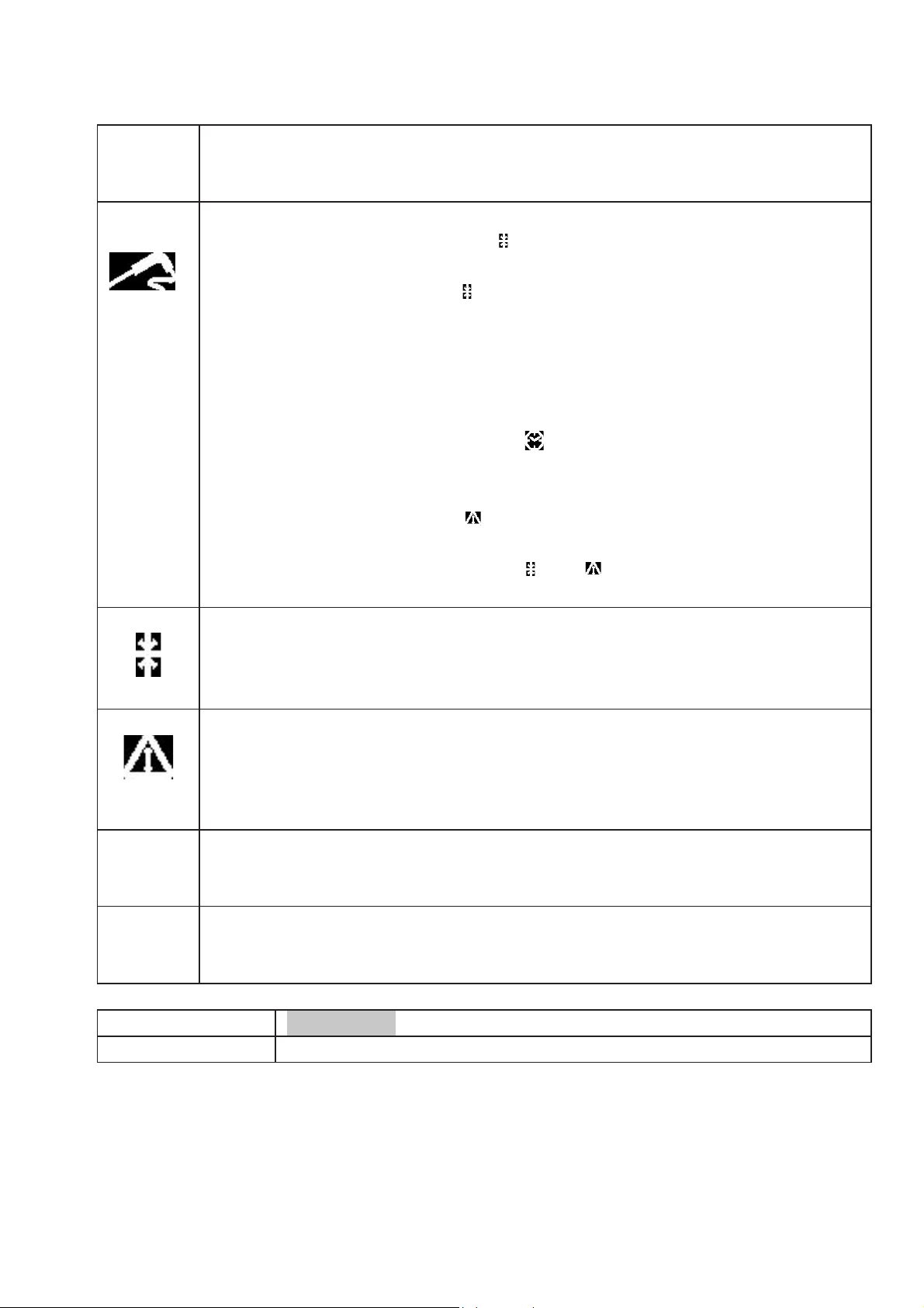
54
controlled blast chilling cycle has been completed
if this LED is flashing, a timer controlled blast chilling and storage cycle
has been selected.
LED temperature controlled blast chilling
• if this LED is on and LED
is off, a temperature controlled blast
chilling cycle is running
• if this LED is on and LED
is on, storage is running after a temperature
controlled blast chilling cycle has been completed
if this LED is flashing, a temperature controlled blast chilling and storage
cycle has been selected.
if this LED comes on for ½ a second every 3 seconds, a needle probe
test is being run
• if this LED is flashing and LED
is on, needle probe testing results
negative (parameters rc and rd) the cycle switches to timer controlled
blast chilling; refer to paragraph 3.6
• if this LED is flashing and is on, chilling has not been completed and
blast chilling will continue.
• if this LED is flashing and LEDs
and are on, blast chilling has not
been completed but the system is now in storage mode
LED storage
if on, the chiller is in storage mode
if this LED is flashing, the working setpoint is being modified during
storage (refer to paragraph 4.1)
°C
LED alarms
if on, an alarm has been activated
LED degree Celsius
if on, the unit of measurement is in degrees Celsius (parameter P2)
°F
LED degrees Fahrenheit
if on, the unit of measurement is in degrees Fahrenheit (parameter P2)
Decimal
point
point LED minute
if flashing, the unit of measure displayed is in
minutes
CODE MEANING
- d -
- d - defrosting or dewatering is running
6 Alarms
6.1 Alarm prompts
Page 23
55
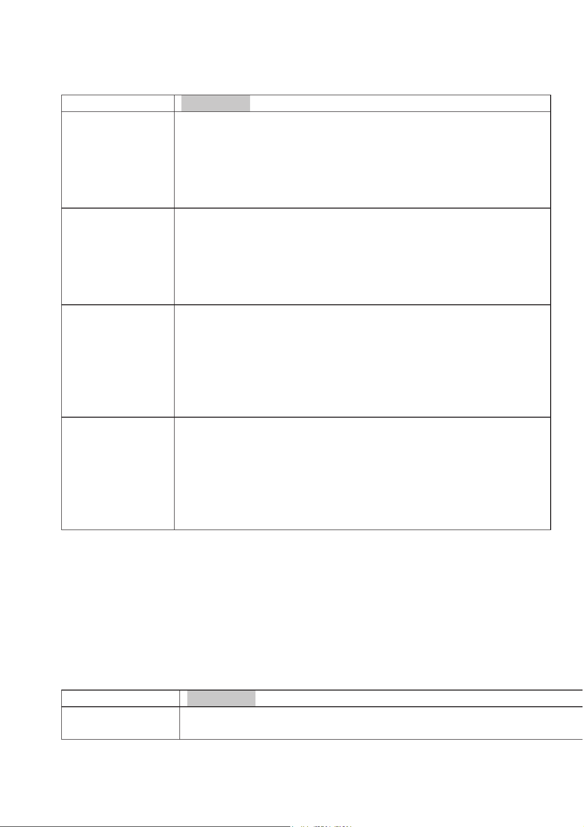
CODE
MEANING
AL
Minimum temperature alarm
Remedies:
• check chiller internal temperature
• refer to parameters A1 and A2
Results :
• the system continues to work regularly
AH
Maximum temperature alarm
Remedies:
• check chiller internal temperature
• refer to parameters A3 and A4
Results :
• the system continues to work regularly
id
Alarm micro-port input (only when in “stand-by” and if
parameter i0 is set at 0 or 1)
Remedies:
• identify the causes which enabled this input
• refer to parameters i0 and i1
Results :
• the resulting condition with parameter i0
iA
Alarm compressor protection input (only if parameter i0 is set at
2)
Remedies:
• identify the causes which enabled this input
• refer to parameters i0 and i1
Results :
• the compressor stops
Once the causes which have tripped an alarm are identified and eliminated, the
system returns to normal and regular functioning.
7 DIAGNOSTIC SYSTEM
7.1 Diagnostic system
CODE
MEANING
Error in chiller compartment probe
Remedies:
Page 24

56
Pr1
• access parameter P0
• check that the probe is intact
• check the connection system – probe
• check chiller internal temperature
Results when the error occurs with the system in “stand-by”:
• if parameter C11 is set at 0, no cycle can be activated
• if parameter C11 is set at 1, the needle probe works as the chiller
compartment probe and only timer controlled cycles can be activated
Results when the error occurs during a timer controlle
d chilling cycle:
• if parameter C11 is set at 0, the cycle running is suspended
• if parameter C11 is set at 1, the needle probe works as the chiller
compartment probe and blast chilling continues
Results when the error occurs during a temperature co
ntrolled chilling
cycle:
• if parameter C11 is set at 0, the cycle running is suspended
• if parameter C11 is set at 1, the probe works both as needle probe and
chiller compartment probe and blast chilling continues
Results when the error occurs during storage:
• if parameter C11 is set at 0, the compressor is managed by parameters
C4, C5 and C6
• if parameter C11 is set at 1, the needle probe works as the chiller
compartment probe and storage continues
Pr2
Error in needle probe
Remedies:
• proceed as above but referring to needle probe
Results when the error occurs with the system in “stand-by”:
• only timer controlled chilling cycles can be activated
Results when the error occurs during a timer controlled chilling cycle:
blast chilling will continue
Results when the error occurs during a temperature controlled chilling
cycle:
blast chilling will continue as a timer controlled cycle
Results when the error occurs during storage:
• storage continues
8 TECHNICAL SPECIFICATIONS
8.1 Technical specifications
Casing: grey coloured and fireproof
Page 25
57
Degree of protection of faceplate: IP 65.
Connections: screw terminals, (power supply, inputs and outputs), 6-pole connector
(serial port upon request); pull-out terminals (power supply, inputs and outputs) upon
request.
Workplace temperature: from 0 to 55°C (10….. 90% humidity without
condensation).
Power supply: 230 VCA, 50/60 Hz, 3 VA (approximately); 115 VCA upon request.
Alarm buzzer: incorporated.
Temperature reading inputs: 2 (chiller compartment probe and needle probe) per
probe
PTC/NTC.
Digital inputs: 1 (microport / multipurpose) per NO/NC contact (dry contact, 5 V1
mA).
Temperature reading range: from –50°C to 150 °C for PTC probe, -40°C to 105°C
for NTC probe.
Resolution: 0.1 °C71 °C/1 °F
Digital outputs: 2 relays
• compressor relay: 16 A res. @ 250 VCA (contact NO) for versions 12
VCA/CC and 12-24 VCA/CC; 8 A res. @ 250 VCA otherwise
• relay defrosting / evaporator fan: 8 A res. @ 250 VCA (change-over
contact).
Maximum allowable current across loads is 10 A.
Serial port: port for communicating with the monitoring system (through a serial
interface, via TTL – transistor to transistor logic – with MODBUS communication
protocol) or with programming key; available upon request.
9 WORKING SETPOINT AND CONFIGURATION PARAMETERS
9.1 First level configuration parameters
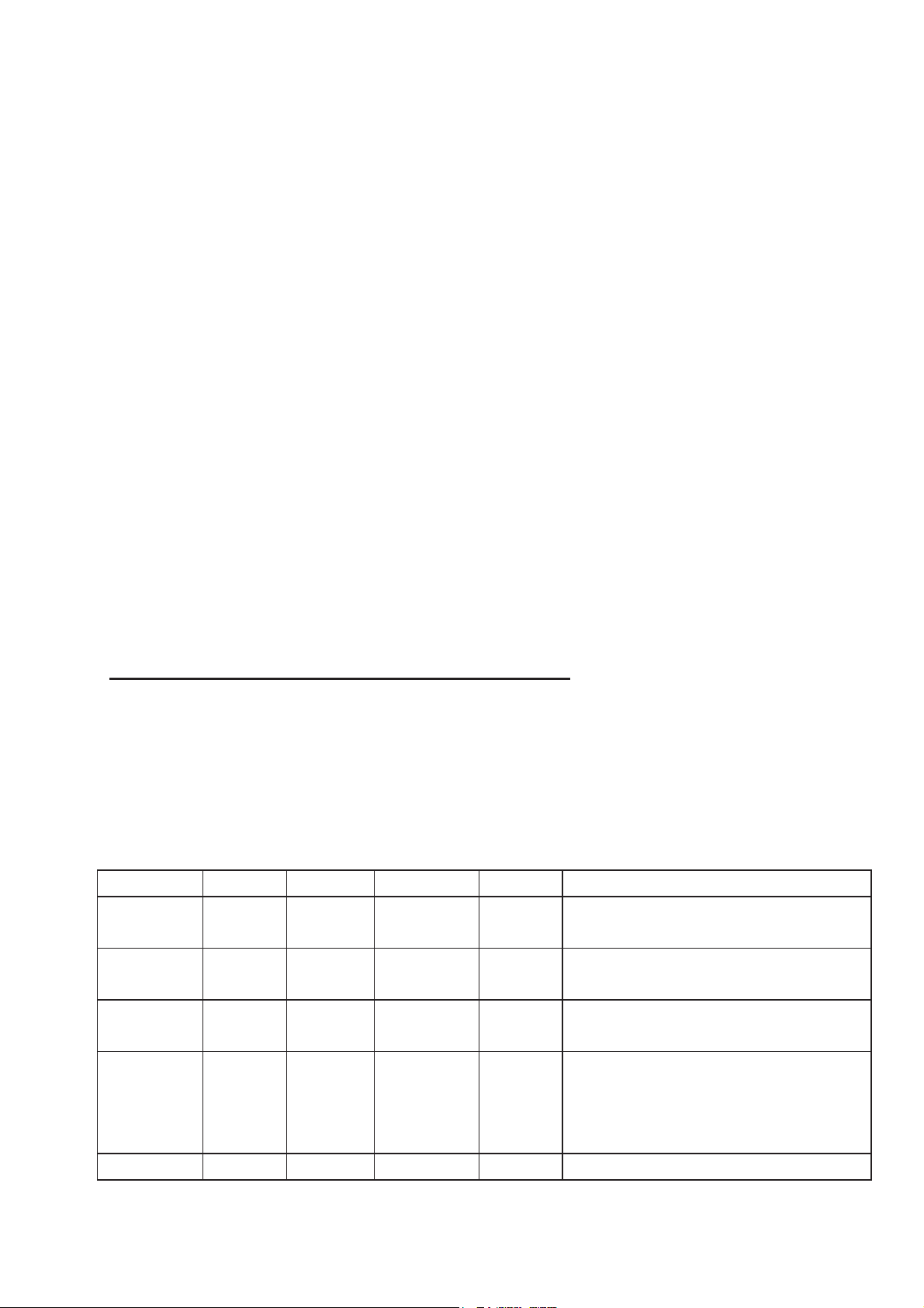
PARAM MIN. MAX. U.M. DEF. MAIN REGULATOR
r0
0.1 15.0 °C/°F(1) 2.0 Differential for parameters r7,
r8, r9 and rA
r1
1 600 Min. 90 time for positive temperature
timer controlled blast chilling
r2
1 600 Min. 240 time for negative temperature
timer controlled blast chilling
r3
-99.0 -99.0 °C/°F(1) 3.0 end of chilling temperature for
positive temperature chilling
(temperature detected by the
needle probe)
r4
-99.0 -99.0 °C/°F(1) -18 end of chilling temperature for
Page 26
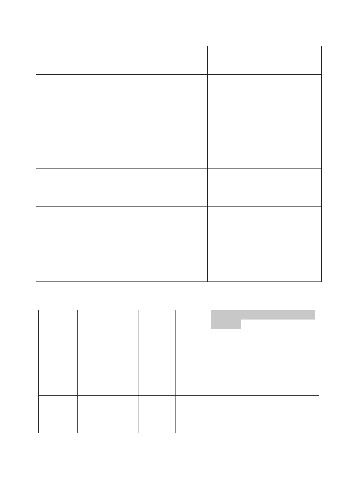
58
negative temperature chilling
(temperature detected by the
needle probe)
r5
1 600 Min. 90 maximum time for positive
temperature controlled blast
chilling
r6
1 600 Min. 240 maximum time for negative
temperature controlled blast
chilling
r7
-99.0 -99.0 °C/°F(1) 0.0 working setpoint during
positive temperature blast
chilling (chiller compartment
temperature)
r8
-99.0 -99.0 °C/°F(1) -40 working setpoint during
negative temperature blast
chilling (chiller compartment
temperature)
r9
-99.0 -99.0 °C/°F(1) 2.0 working setpoint during storage
after positive temperature blast
chilling (chiller compartment
temperature)
rA
-99.0 -99.0 °C/°F(1) -20.0 working setpoint during storage
after negative temperature blast
chilling (chiller compartment
temperature)
9.2 Second level configuration parameters
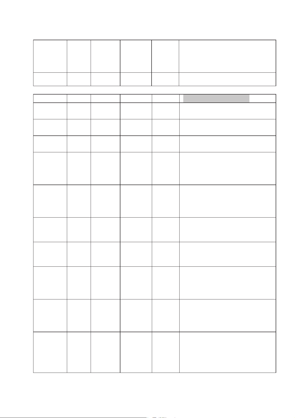
PARAM MIN. MAX. U.M. DEF. TEMPERATURE READING
INPUTS
CA1 -25.0 25.0 °C/°F(1) 0.0 offset chiller compartment
probe
CA2 -25.0 25.0 °C/°F(1) 0.0 offset needle probe
P0
0 1 --- 0 type of probe
0 = PTC
1 = NTC
P1
0 1 --- 1 decimal point degree Celsius
(for the reading displayed
during normal functioning)
1 = yes
Page 27
59
P2
0 1 --- 0 unit of measurement
temperature (2)
0 = °C
1 = °F
P3
0 1 --- 1
needle probe enabled
1 = yes
PARAM MIN. MAX. U.M. DEF. MAIN REGULATOR
r0
0.1 15.0 °C/°F(1) 2.0 differential for parameters r7,
r8, r9 and rA
r1
1 600 min 90 time for positive temperature
timer controlled blast chilling
r2
1 600 min 240 time for negative temperature
timer controlled blast chilling
r3
-99.0 99 °C/°F(1) 3.0 end of chilling temperature for
positive temperature chilling
(temperature detected by the
needle probe)
r4
-99.0 99 °C/°F(1) -18.0 end of chilling temperature for
negative temperature chilling
(temperature detected by the
needle probe)
r5
1 600 min 90 maximum time for positive
temperature controlled blast
chilling
r6
1 600 min 240 maximum time for negative
temperature controlled blast
chilling
r7
-99.0 99 °C/°F(1) 0.0 working setpoint during
positive temperature blast
chilling (chiller compartment
temperature)
r8
-99.0 99 °C/°F(1) -40.0 working setpoint during
negative temperature blast
chilling (chiller compartment
temperature)
r9
-99,0 99 °C/°F(1) 2.0 working setpoint during
storage after positive
temperature blast chilling
(chiller compartment
temperature)
Page 28
60
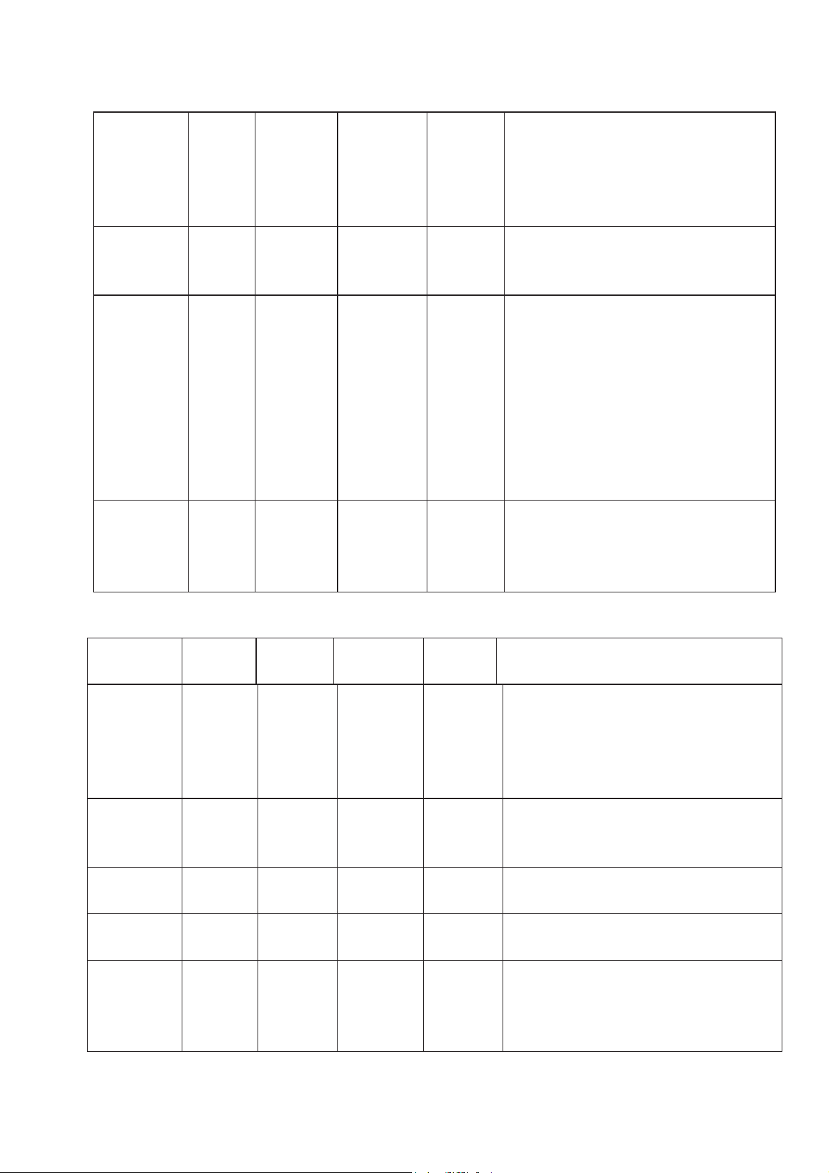
rA
-99.0 99 °C/°F(1) -20.0 working setpoint during
storage after negative
temperature blast chilling
(chiller compartment
temperature)
rb
0 1 --- 1 enable negative blast chilling
cycle and storage
1 = yes
rc
0.0 99 °C/°F(1) 5.0 difference (temperature
detected by the needle probe –
chiller compartment probe” for
the first step when testing the
needle probe is inserted
correctly (refer to paragraph
3.6)
0= test not run (neither the first
nor second step)
rd
1 99 S 60 during the second step of the
test to check that the needle
probe is inserted correctly
(refer to paragraph 3.6)
PARAM MIN. MAX. U.M. DEF. COMPRESSOR
PROTECTIONS
C0 0 240 min 0 delay in compressor activation
after a cycle has been started;
delay in compressor activation
after the power supply has been
restored.
C1 0 240 Min 5 minimum time between two
consecutive compressor startups.
C2 0 240 Min 3 minimum duration of
compressor shut-down
C3 0 240 S 0 minimum duration of
compressor start-up
C4 0 240 Min 10 compressor shut-down time
during an error alarm chiller
compartment probe when in
storage mode; refer to C5 and
Page 29
61
C6 (only if C11 =0)
C5 0 240 -{}-Min 10 compressor start-up time during
an error alarm chiller
compartment probe when in
storage mode; refer to C4 (only
if C11 =0)
C6 0.0 240 min 20 compressor start-up time during
an error alarm chiller
compartment probe when in
negative temperature storage
mode; refer to C4 (only if C11
=0)
C11 0.0 200.0 °C/°F
(1)
90.00 needle probe function during
error chiller compartment probe
0 = needle probe
IF THE ERROR OCCURS
WHEN IN “STAND-BY” – it is
not possible to run a cycle
IF THE ERROR OCCURS
DURING EITHER TIMER OR
TEMPERATURE
CONTROLLED BLAST
CHILLING – the cycle is
suspended
IF THE ERROR OCCURS
DURING STORAGE
1 = both as needle probe and
chiller compartment probe
IF THE ERROR OCCURS
WHEN IN “STAND-BY” – the
needle probe functions as chiller
compartment probe and only
timer controlled cycles can be
run
IF THE ERROR OCCURS
DURING A TIMER
CONTROLLED BLAST
CHILLING CYCLE – the
needle probe functions as the
chiller compartment probe and
chilling continues
Page 30
62
IF THE ERROR OCCURS
DURING A TEMPERATURE
CONTROLLED BLAST
CHILLING CYCLE – the
needle probe functions as both
needle probe and chiller
compartment probe and the
blast chilling cycle continues;
we recommend that parameter
i0 is set to 2 (COMPRESSOR
PROTECTION)
IF THE ERROR OCCURS
DURING STORAGE – the
needle probe functions as the
chiller compartment probe and
storage continues
PARAM MIN. MAX. U.M. DEF. DEFROSTING
d0 0 99 h 8 defrosting interval (3)
0 = interval defrosting is never
activated
d3 0 99 min 30 defrosting time
0 = defrosting is never activated
d7 0 15 min 2 dewatering time
PARAM MIN. MAX. U.M. DEF. TEMPERATURE ALARMS
A1 0 99.0 °C/°F
(1)
10.0 temperature below alarm limit
the minimum temperature alarm
is activated; refer to A2 (5)
A2 0.0 1 --- 1 type of minimum temperature
alarm
0 = no alarm
1 = refers to parameters r9 and
rA (namely “r9 – A1” and “rA –
A1”)
A4 0.0 99.0 °C/°F(1) 10.0 temperature above alarm limit
the maximum temperature alarm
is activated; refer to A5 (5)
Page 31
63
A5 0 1 --- 1 type of maximum temperature
alarm
0 = no alarm
1 = refers to parameters r9 and
rA (namely “r9 + A4” and “rA +
A4”)
A6 0 240 min 15 delay in temperature alarm from
when chiller goes into storage
mode
A7 0 240 min 15 temperature alarm delay
A8 0 240 min 15 delay in maximum temperature
alarm after dewatering has
terminated (6)
A9 0 240 min 15 delay in maximum temperature
alarm from when the microport
input is disabled (only if i0=0
or 1) (7)
AA 0 240 s 5 buzzer duration time when
chilling has been completed
PARA
M
MIN. MAX. U.M. DEF. EVAPORATOR FAN only if U0
= 1
F0 0 2 --- 2 evaporator fan during blast chilling
0 = off
1 = on
2 = in parallel with compressor
F2 0 2 --- 1 evaporator fan during storage
0 = off
1 = on
F8 0 99 min 0 delay in evaporator fan during
defrosting from when one of the
following digital input functions
PARAM MIN. MAX. U.M. DEF. DIGITAL INPUTS
i0 0 2 --- 1 is enabled
0 = INPUT MICROPORT – in
this case parameters i1, i2 and i3
are active; when the input is
Page 32
64
enabled the evaporator fan is
turned off (maximum for the time
i3 or when the input is disabled)
(8)
1 = INPUT MICROPORT – in
this case parameters i1, i2 and i3
are active; when the input is
enabled the compressor is shutdown and the evaporator fan is
turned off (maximum for the time
i3 or when the input is disabled)
(8) (9)
2 = COMPRESSOR
PROTECTION – in this case
parameters i1 and i7 are active; the
compressor is shut-down, code
“iA” flashes on the display and the
buzzer is activated (until the input
is disabled)
i1 0 2 --- 2 type of contact for the digital input
0 = NO (input enabled with
contact closed)
1 = NO (input enabled with
contact opened)
2 = no input
i2 -1 120 min 30 delay in prompt for alarm input
microport (only if i0 = 0 or 1)
-1 = no alarm prompt
i3 -1 120 min 15 maximum duration caused when
the input microport is enabled
(only if i0 = 0 or 1)
-1 = the resulting condition
remains until input is disabled
i7 0 120 min 0 delay in compressor from when
the input compressor protection is
disabled (only if i0 = 2)
Page 33
65
PARAM MIN. MAX. U.M. DEF.
u0 0 1 --- 1 function managed by relay K2
(refer to paragraph 2.3)
0 = defrosting
1 = evaporator fan
PAR
AM
MIN. MA
X.
U.M. DEF. SERIAL NETWORK (MODBUS)
LA 1 247 --- 247
Lb 0 3 --- 2 baud rate
0=2400 baud
1=4800 baud
2=9600 baud
3=19200 baud
LP 0 2 --- 2 equality
0= none
1=odd
2=even
PARAM MIN. MAX. U.M. DEF. RESERVED
E9 0 1 --- 1
reserved
(1) the unit of measurement is managed by parameter P2
(2) set appropriate regulator parameters after modifying parameter P2
(3) the system memorises defrosting intervals every 30 minutes; a modification to
parameter d0 comes into effect after the defrosting interval has been completed or
from when manual defrosting is activated
(4) temperature alarms are only enabled when the chiller is in storage mode
(5) the parameter differential is 2.0 °C / 4 °F
(6) during defrosting and dewatering temperature alarms are inactive if activated
after defrosting has commenced
(7) when the input microport is enabled the maximum temperature alarm is inactive
if activated after the input has been enabled
(8) the evaporator fan is turned off as long as defrosting is not running
(9) the compressor and the evaporator fan are shut-down 10 seconds after the input is
enabled
 Loading...