


Easy Onion Slicer™
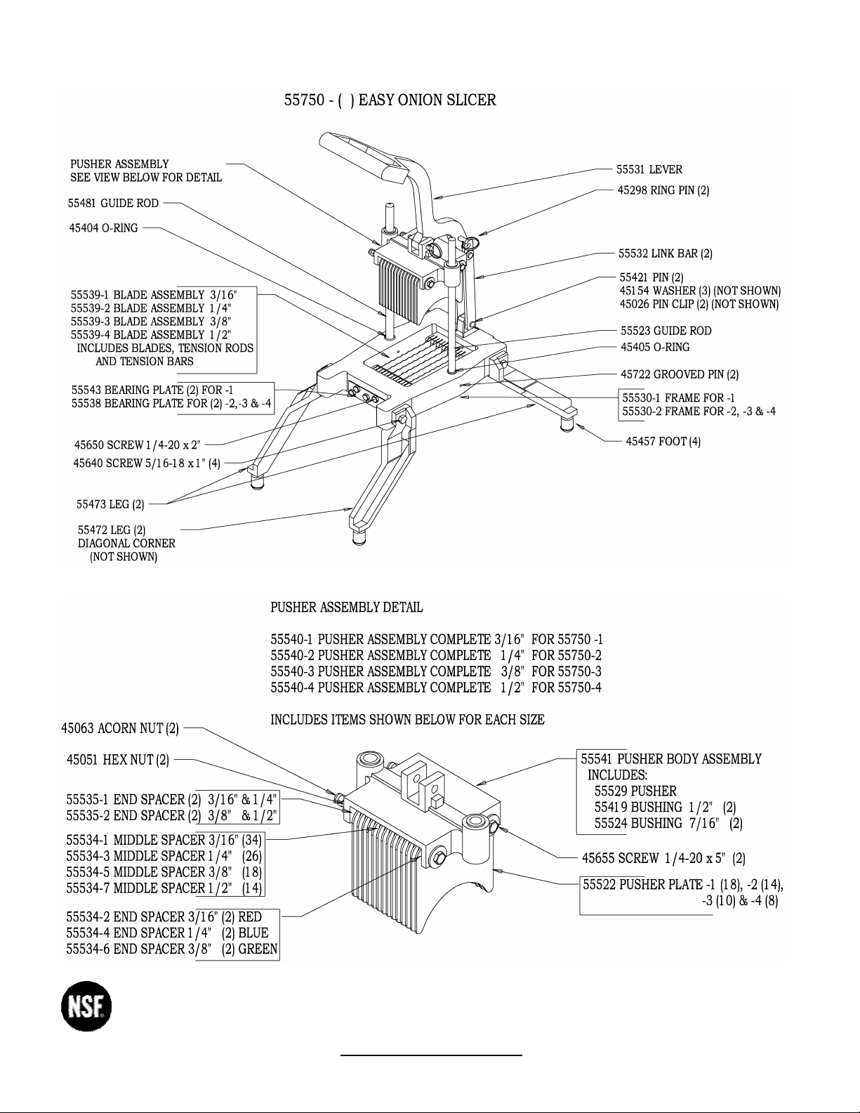
N55750-1 3/16” Slicer
N55750-2 1/4” Slicer
N55750-3 3/8” Slicer
N55750-4 1/2” Slicer
OPERATING INSTRUCTIONS
Important
1. To get the best operation and life from your machine, please read and comply with these instructions.
2. Clean machine thoroughly before and after each use using cleaning instructions below.
3. Minimize the use of alkaline cleaners as they may cause pitting and dulling of the finish.
Safety Instructions
Remember the blades are VERY SHARP! Be careful when handling and operating the machine to keep hands away from the blades
Preparation Instructions
1. The LEVER can be locked in the up position to safely and conveniently clean BLADE ASSEMBLY and PUSHER ASSEMBLY. Raise the
LEVER so hole aligns with the holes in LINK BARS and insert the PIN through all three parts.
2. Insert PIN through hole while the machine is in use.
3. If unit fails to work properly when first operated call NEMCO customer service at 1-800-782-6761
To Operate
1. Hold LEVER in its upper position and place the produce so it is near the center of the blade pattern. NOTE; the blades are very sharp!
2. Remove hand/fingers from the cutting area and with one quick motion bring LEVER down to cause the PUSHER ASSEMBLY to force the
produce through the BLADES then lift and repeat.
To Clean
1. The slicer is easily disassembled for cleaning:
2. To remove the PUSHER ASSEMBLY, remove PIN, move LEVER out of the way and lift PUSHER ASSEMBLY off of the GUIDE RODS.
Reassemble by reversing the procedure.
3. To remove the BLADE ASSEMBLY, remove the screws from both ends of FRAME (see special instructions for reinstallation).
Special Re-assembly and Installation Instructions
To Install Blade Assembly in Frame:
1. Lock LEVER in the up position per Preparation Instructions.
2. Hold BLADE ASSEMBLY in position in the FRAME (the sharp side should be up!).
3. Insert a screw through the BEARING PLATE and the FRAME and loosely thread into the appropriate hole in the TENSION BAR.
4. Repeat on the opposite end of the machine.
5. Proceed to install the remaining screws through the BEARING PLATES and into the TENSION BARS, keeping them loose.
6. Firmly tighten all screws at the end where the LEVER is attached.
7. Tighten the screws at the LEVER HANDLE end as follows:
a) Tighten all screws to a snug condition.
b) N55750-1 has three tiers of BLADES and two TENSION BARS at each end of BLADE ASSEMBLY. Tension the top row of BLADES
first by tightening the four screws across the top row, the inside two screws first, then the outside screws. Repeat the sequence
making the four screws somewhat tighter each time until all four are very tight, and the BLADES “hum”: when they are plucked like
a guitar string. (Tightening torque to be 80 in./lbs.) NOTE: BLADES ARE SHARP, STRUM SIDE OPPOSITE SHARP EDGE
c) Using the other five screws tensions the bottom two tiers of BLADES. Tighten the two top screws first, then the two bottom screws
next, then the middle last. Repeat this sequence making all five screws somewhat tighter each time until all five are very tight and
the BLADES “hum” when they are plucked. (Tightening torque to be 95 in./lbs.)
d) For Models N55750-2, -3, or –4, these machines have only two tiers of BLADES and a single TENSION BAR at each end of BLADE
ASSEMBLY; therefore, omit Step B.
To Lubricate
Lubricate GUIDE RODS with mineral oil or a “food grade” lubricant as needed. DO NOT LUBRICATE WITH COOKING OIL – IT GETS STICKY!
To Replace Blades
Disassemble per To Clean. Install the replacement BLADE ASSEMBLY per Special Re-assembly and Installation Instructions.
2
NEMCO FOOD EQUIPMENT 301 Meuse Argonne, Hicksville, OH 43526
Phone: (419) 542-7751 Fax: (419) 542-6690 Toll free: 1-800-782-6761 45582
www.nemcofoodequip.com 10/30/03
 Loading...