

Page 1
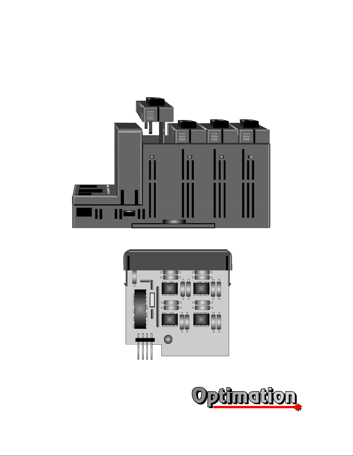
OptiLogic Series
Opti
Logic
Optimal Automation for Industry
Input/Output Modules
Optimation, Inc.
(256)883-3050 1
www.optimate.com
Page 2

OptiLogic Series
WARNING
Thank you for purchasing industrial control products from Optimation, Inc. We want your new
system to operate safely. Anyone who installs or uses this equipment should read this manual
(and any other relevant publication) before installing or operating the system.
To minimize the risk of potential safety problems, you should follow all applicable local and
national codes that regulate the installation and operation of your system. These include the
National Fire Code, National Electric Code, and other codes of the National Electrical
Manufacturer’s Association (NEMA). There may be local regulatory or governmental offices
that can help determine which codes and standards apply to your situation. It is your
responsibility to determine which codes and should be followed, and to verify that the
equipment, installation, and operation is in compliance with the latest revision of these codes. If
you have any questions concerning the installation and operation of Optimation products, please
call us at (256)883-3050.
All Optimation products are warranted against defects in materials and workmanship for a period
of one year from the date of shipment. Warranty applies to unmodified product under normal
and proper use and service. Optimation’s sole obligation under this warranty shall be limited to
either, at Optimation’s option, repairing or replacing defective product. The cost of freight to
and from Optimation will be borne by the customer. No other warranty is given or implied.
This publication is based on information that was available at the time it was printed. We
constantly strive to improve our products and services, so we reserve the right to make changes
to the products and/or publications at any time without notice and without any obligation. This
publication may also discuss features that may not be available in certain revisions of the
product.
Trademarks
This publication may contain references to products produced and/or offered by other
companies. These products and company names may be trademarked and are the sole property
of the respective owners. Optimation disclaims any proprietary interest in the marks and names
of others.
Copyright 1999, Optimation, Inc.
All rights reserved
No part of this document shall be copied, reproduced or transmitted in any way without the prior,
written consent of Optimation, Inc. Optimation retains the exclusive rights to all information
included in this document.
Optimation, Inc.
(256)883-3050
www.optimate.com
2
Page 3

OptiLogic Series
Table of Contents
Introduction . . . . . . . . 6
Digital Inputs . . . . . . . . 7
Input Isolation . . . . . . . 7
DC Inputs . . . . . . . . 7
AC Inputs . . . . . . . . 8
Digital Input Voltage . . . . . . 8
I/O “Common” Terminals . . . . . 8
Digital Outputs . . . . . . . 9
Relay Outputs . . . . . . . 9
Transistor Outputs . . . . . . . 10
NPN Transistor Sinking Outputs . . . . 10
Solid State Relay Outputs . . . . . . 10
Analog Inputs . . . . . . . . 11
Isolation . . . . . . . . 11
Resolution . . . . . . . . 12
Accuracy . . . . . . . . 12
Range . . . . . . . . . 12
Multiplexing . . . . . . . . 12
Single Ended Inputs . . . . . . 13
Differential Inputs . . . . . . . 13
OL2104 Isolated Relay Output Module . . . 14
OL2108 Relay Output Module . . . . . 15
OL2109 DC Sinking Output Module . . . 16
OL2111 AC Solid State Relay Module . . . 17
OL2201 Digital Input Simulator Module . . . 18
OL2205 Isolated AC/DC Input Module . . . 19
OL2208 DC Digital Input Module . . . . 20
OL2211 AC Digital Input Module . . . . 21
OL2252 Dual High Speed Pulse Counter . . . 22
OL2258 High Speed Pulse Counter . . . . 25
OL2304 4 Channel Analog Voltage Output . . 28
OL2408 Analog Voltage Input Module . . . 29
OL2418 Analog Current Input Module . . . 30
Optimation, Inc.
(256)883-3050 3
www.optimate.com
Page 4

OptiLogic Series
OL2602 Dual RS232 Module . . . . . 31
Optimation, Inc.
(256)883-3050
www.optimate.com
4
Page 5

www.optimate.com
R
evision History
Issue
Date
Pages
Description
Original 8/99
1.1
1.2
1.3
1.4
1.5
Optimation, Inc. (256)883-3050 5
1-24
1/00
9/00
04/01
09/02
13, 18, 25
25-28
various
15
10/2012 14, 15
Original release
Added OL2104, OL2205, OL2418
Added OL2258, OL2304
Added specs requested by UL
Changed wording of OL2108 voltage rating spec
Changed voltage ratings of OL2104 and OL2108
to match UL ratings
Page 6
OptiLogic Series
OptiLogic Input/Output Modules
Introduction
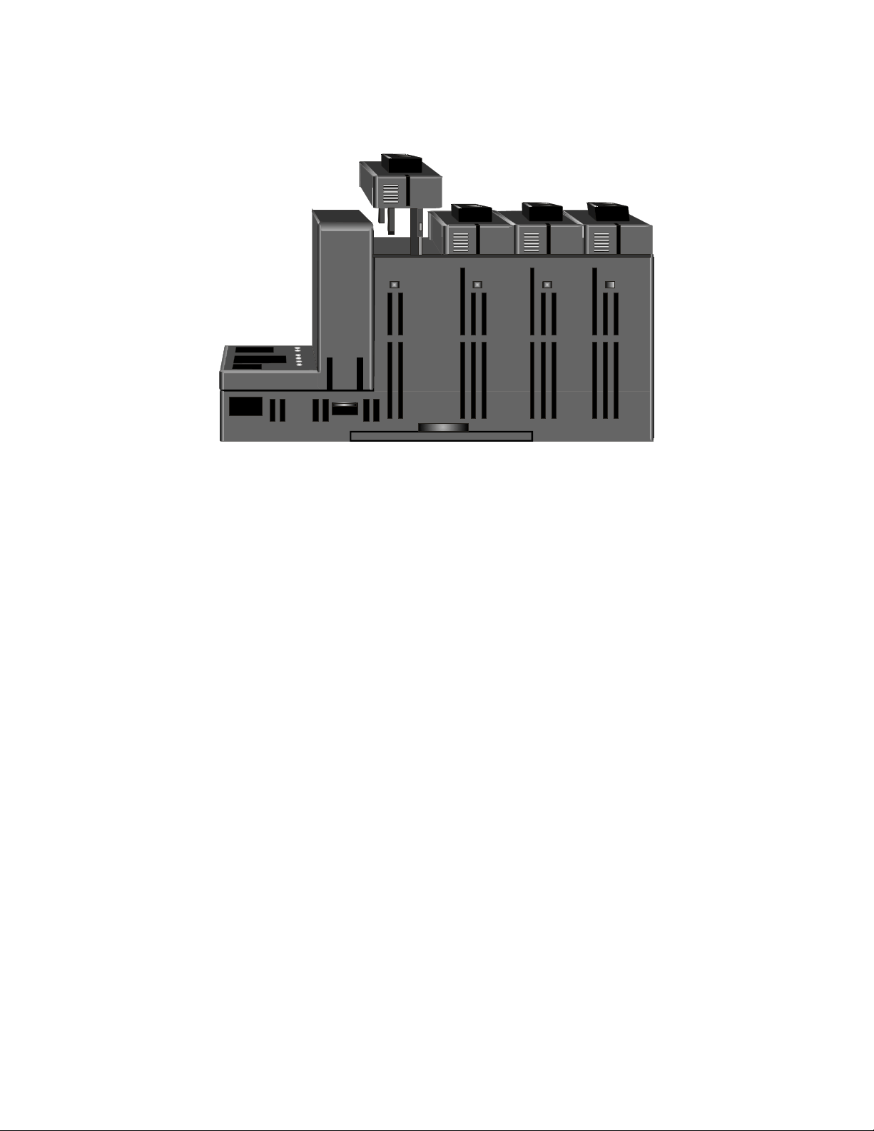
Optimation’s OptiLogic series is a
flexible, modular system, designed to allow you
the ability to configure an optimal solution for
your exact needs. To accomplish this goal,
Optimation has developed a series of I/O
modules, communications modules, specialty
modules and operator panels that can be plugged
together in nearly any combination. This
manual covers the currently available modules
that plug into the card cage.
Additional I/O modules are under
development. Please check our web site at
optimate.com for a complete list of available
modules.
Most OptiLogic modules can be installed
in any card cage slot and used in any
combination and quantity that will fit in the card
cage. This applies to all general purpose digital
and analog I/O. If you need all digital inputs plug in digital input modules only. If you need a
mixture of analog and digital inputs and output select the mixture that fits your needs. Snap
together modularity gives you the ability to
optimize your system for your needs.
OptiLogic I/O modules are designed to
meet your needs in real world application. They
are all small circuit boards with a few available
points to minimize your system cost. Most
module connectors are pluggable terminal strips
for easy connection, and easy maintainability.
The snap-together design means low labor costs
- or costs on your time. Visual status indicators
on digital I/O and communications modules
provide a convenient means for monitoring
operation. All together, the result is a cost
effective, easy to use and maintain set of
industrial control hardware.
This manual covers general I/O
characteristics and applications first. Specific
I/O boards are covered in the latter pages. The
general pages should serve as a guide to
selecting and installing I/O boards in your
application.
Communications and specialty modules
are covered in the latter pages of this manual.
It is Optimation’s desire for this manual
to serve as a guide in your selection of the
modules appropriate for your application, as
well as to provide complete information for their
use.
Optimation, Inc.
(256)883-3050
www.optimate.com
6
Page 7
OptiLogic Series
processor
Sourcing DC input
Digital Inputs
Digital I/O modules are used to either
monitor (input) or control (output) the “state” of
something. “State” being on or off, active or
inactive, open or closed - etc. In the “real world”
digital I/O requirements come in a variety of
shapes and sizes. Therefore, there are a variety
of available modules designed to meet the
variety of needs.
Typical digital inputs are connected to
switches, buttons, digital outputs from other
equipment, discrete level sensors, thermostats
and other on/off sensing devices.
Digital status is sensed by a controller,
such as an OptiLogic system, by passing current
through an input sensor. When the current is on,
the input state is active. When it is not there, the
input state is inactive.
Input Isolation
In most cases, it is important to “isolate”
the real world inputs from the internal
electronics of the controller. You want to
prevent some external situation from “zapping”
the controller’s electronics.
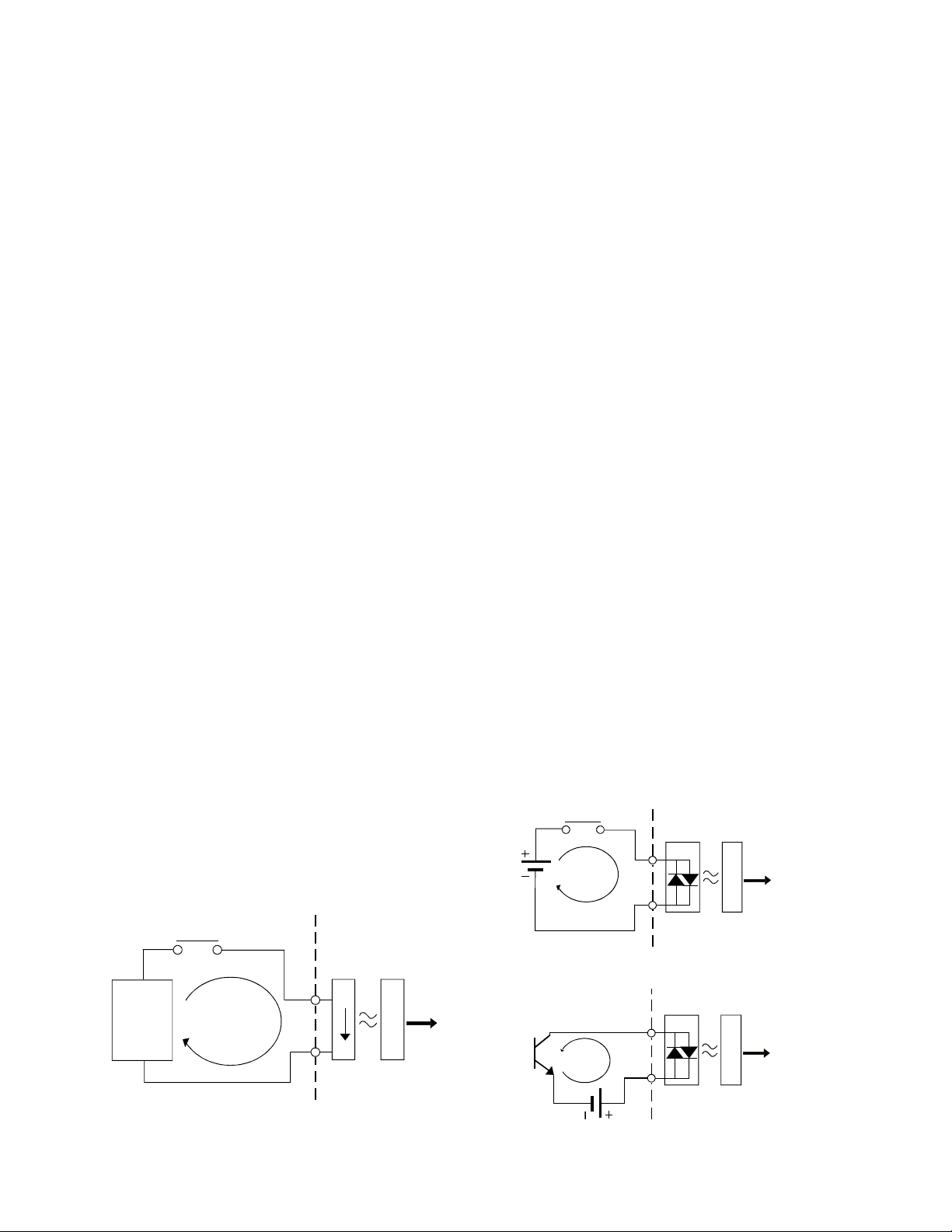
figure shown, when the digital input contact
closes, the circuit path is complete and current
will flow. On the input module this circuit path
passes through a device which emits light when
current flows through it. The light emitter is in
very close physical proximity to (actually in the
same chip) a photo sensor, which will turn on
when it senses light. In this way, a digital input
module can sense whether the input device is
closed (current flow) or open (no current flow)
without a direct electrical connection between
the external sensor and the internal electronics.
DC Inputs
DC digital inputs are typically supplied
by a DC power supply. The most common DC
supplies used in industry are 12VDC and
24VDC.
Typical DC digital input circuits are
shown below. As shown, the physical optical
emitter on the input module is an LED (light
emitting diode). OptiLogic DC inputs use
bidirectional LEDs - i.e. Your inputs may either
source or sink current. The top figure shows a
sourcing input. The figure below it shows a
sinking input. When inputs are connected to a
“common” (most instances), inputs must be
either all sourcing or all sinking.
electrical isolation is optical isolation. The
figure below illustrates the basic concepts of
optical isolation of a digital input circuit. In the
Power
source
Optimation, Inc.
An effective means of providing such
sensor
optical
isolation
To
OptiLogic
Input module
(256)883-3050 7
www.optimate.com
sensor
common
Sinking DC input
common
optical
isolation
OptiLogic
processor
Input module
optical
isolation
OptiLogic
processor
Input module
To
To
Page 8
OptiLogic Series
Sourcing
10-30VDC
processor
AC Inputs
AC digital inputs are typically supplied
either directly from line voltage or transformed
down from line voltage. The most common AC
inputs are 120VAC and 24VAC, although any
voltage range is possible.
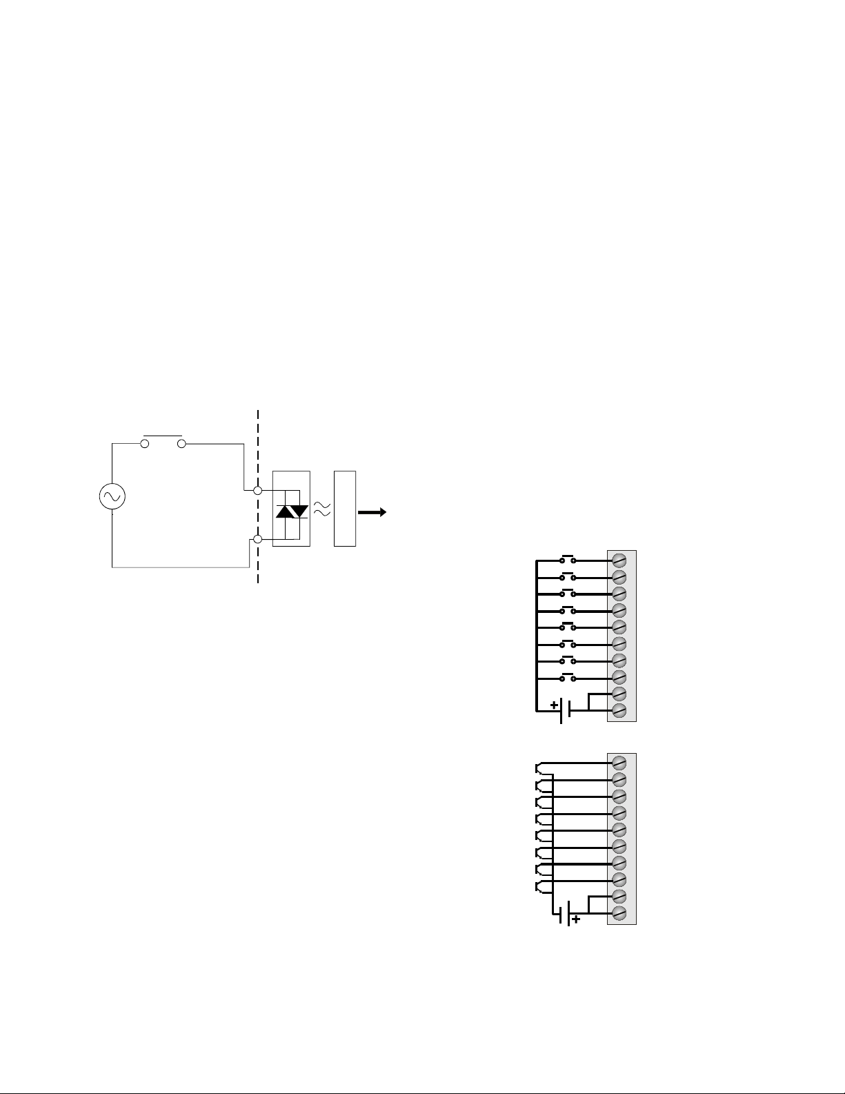
A typical AC input circuit is shown
below. As shown, the physical optical emitter
on the input module consists of two LEDs of
opposite polarity. An AC (alternating current)
connection flows current one way, then the
other. Light is emitted in both cases.
sensor
optical
isolation
To
OptiLogic
maximum voltage corresponds to the maximum
current the optocoupler can handle without
being damaged.
I/O “Common” Terminals
For a digital input circuit, one input
terminal and one output terminal is necessary for
operation. For practical application, one of these
two terminals may be “common” to several
circuits.
In most systems, the power source for all
digital inputs is from the same supply. In such
cases, connecting all of the circuit return lines
together results in reduced equipment costs as
well as simpler system wiring.
The example below illustrates a digital
input board that has eight inputs and two
commons. This can be accomplished with a 10
terminal connector block.
Input module
There is a short period when voltage, and
therefore current flow, switches from one
direction to the other when no current flows.
This is called zero crossover. During zero
crossover, the digital input circuit must
“debounce” the signal to ensure that the system
does not provide a false indication that the input
contact is not closed when it is, in fact, closed.
OptiLogic AC digital inputs handle such zero
crossover conditions.
Digital Input Voltage
Any digital input module, AC or DC, is
designed to operate within an input voltage
range. The input voltage directly controls the
amount of current flowing through the circuit.
The minimum voltage corresponds to a voltage
that creates enough current to produce LED light
sufficient to be sensed by the optical sensor. The
IN7
IN6
IN5
IN4
IN3
IN2
IN1
IN0
10-30VDC
Sinking
IN7
IN6
IN5
IN4
IN3
IN2
IN1
IN0
10
9
8
7
6
5
4
3
2
1
10
9
8
7
6
5
4
3
2
1
Optimation, Inc.
(256)883-3050
www.optimate.com
8
Page 9
OptiLogic Series
Digital Outputs
Digital outputs are used to turn “loads”
on and off. “Loads” may be lights, motors,
solenoids, or any type of on/off device found in
the “real world”.
Digital outputs in the OptiLogic series
come in three types - relay, transistor and solid
state relay. Each type has applications it is best
suited for. The following is a general list of
application characteristics for each output type.
Relay
•
Low contact loss
•
AC or DC
•
Moderate to high current rating
•
Low cost
Should not be used for
•
Ultra low current switching (less than 10mA)
•
Switching loads at high frequency
Transistor
•
DC application only
•
Low current rating
High frequency switching
•
•
Low cost
Relay Loads
Relays are affected by the type of load
that is switched. Inductive loads (solenoids,
motors, etc.) tend to wear the relay much more
than resistive loads (lights, heaters, etc.).
Inductive load wear is due to the fact that
inductive loads will continue to conduct current
for a period, even after the circuit is broken. This
current flow builds up opposing polarity charges
between the contact segments that just
separated. This makes the two segments attract
each other - making opening the contact more
difficult. It also can result in arcing while the
contact is being opened. Arcing, in turn, builds
up carbon deposits, i.e. wear.
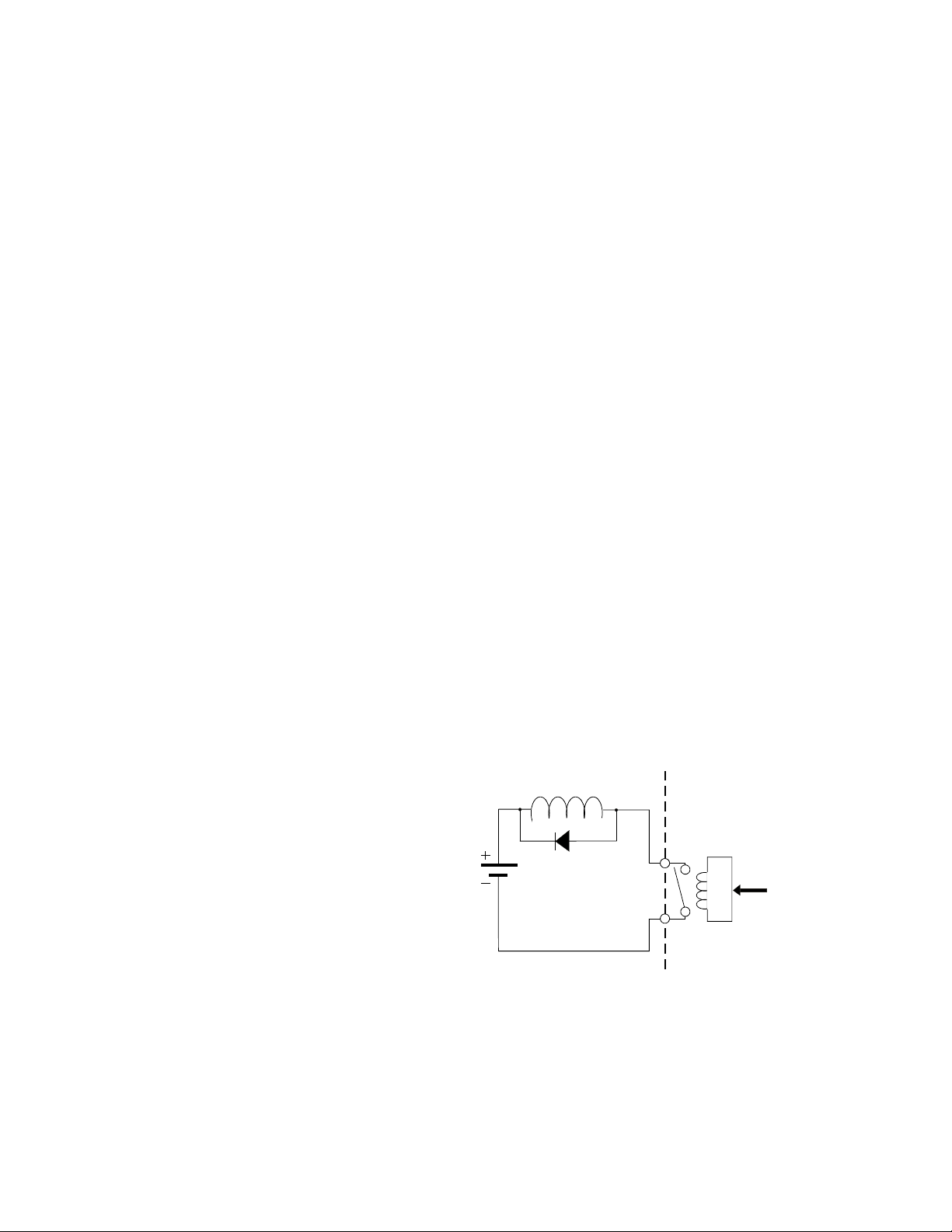
This situation can be improved for DC
inductive circuit loads by the addition of
external diode protection of the circuit. The
figure below illustrates diode protection. When
the contact is closed, the diode is reverse biased
and no current flows through it. When the
contact opens, current will continue to flow
through the inductive load. The diode provides a
path for current flow. The result that is the
energy is dissipated in the inductive coil and not
the relay contact.
Inductive load
Solid State Relay
•
AC application
•
Any switching frequency
•
Moderate current
•
Moderate cost
Relay Outputs
Relays are basically electrically
controlled mechanical switches. All current
OptiLogic Relay output boards utilize form A
relays - i.e. the contact is either open or closed.
Optimation, Inc.
(256)883-3050 9
www.optimate.com
Diode protection
isolation
From
OptiLogic
processor
Output module
Note : Do not use this circuit for AC loads.
Page 10
OptiLogic Series
processor
processor
Transistor Outputs
NPN Transistor Sinking Outputs
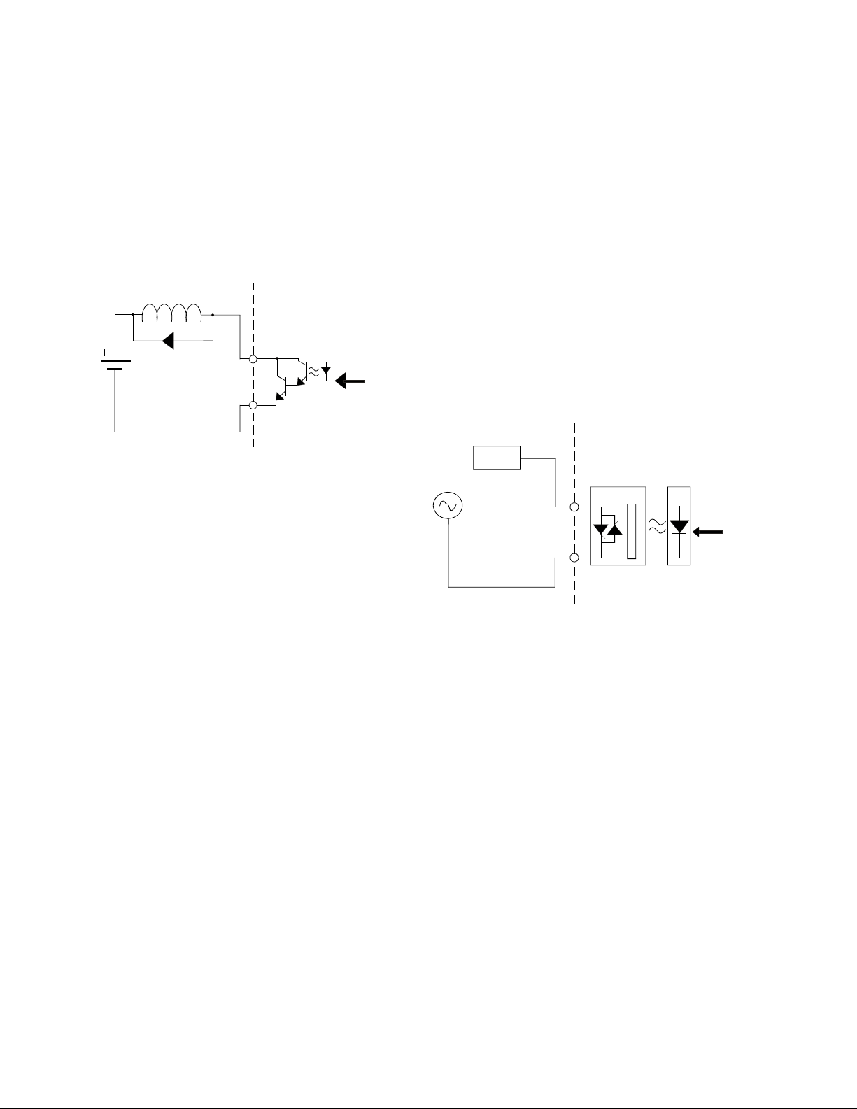
An NPN transistor sinking output
provides a path to ground. A typical circuit is
shown below.
Inductive load
optical
Diode protection
There is a small voltage drop across the
transistor in such a circuit. The voltage drop will
generate heat in the transistor. Therefore NPN
transistor outputs are generally limited to lower
current applications.
isolation
From
OptiLogic
Output module
Solid State Relay Outputs
Solid state relays are semiconductor
switches that operate very much like mechanical
relays. They have an advantage over mechanical
relays by virtue of the fact that they are
semiconductors. Solid state relays can be
switched at relatively high frequencies and they
do not wear out. However they are more
expensive and there is a small voltage drop
across the contact.
The figure below illustrates a typical
solid state relay output. OptiLogic Solid state
relays are designed for AC load operation.
load
optical
isolation
From
OptiLogic
Transistor outputs can be operated at
high frequency. There is no effective wear on a
transistor output from switching, as there is in a
mechanical relay.
Diode protection applied to inductive
loads is recommended in cases where the load
current approaches the rated current limit of the
output. In most cases OptiLogic outputs are
designed to withstand voltages of at least twice
the rated output voltage. However, diode
protection like that shown above will ensure that
turn off voltage spikes will never get to that
level.
Output module
Optimation, Inc.
(256)883-3050
www.optimate.com
10
Page 11

OptiLogic Series
Analog Inputs
Analog inputs are used to monitor the
value of some continuously variable
measurement. Typical analog inputs are
measurements of temperature, pressure, weight,
liquid level, pH, flow rate and many other “real
world” parameters.
The purpose of an analog input module is
to convert the measurement into a format that is
usable by the data acquisition or control system.
To be usable by an computer-based system, the
analog measurement must be converted to
digital format. Doing so accurately and, in some
cases, quickly, is the goal of the analog to digital
converter module.
also use the main power supply and isolated
power via a switching power converter and a
transformer. There are OptiLogic analog input
modules in both categories. Neither is
functionally superior to the other. The on-board
power generation may save the cost of an
additional external power supply.
Analog
inputs
A/D
Converter
Bus
Interface
A good understanding of analog input
modules includes an understanding of isolation,
accuracy, single and differential inputs,
multiplexing, resolution and range. The
following paragraphs provide an overview of
these subjects.
Isolation
In many applications there is a good deal
of benefit to be derived from isolating the analog
measurement source from the RTU’s power
supply. In some cases, signal inputs may contain
voltages or noise signals which could adversely
affect the main processor’s operation. Likewise,
noise on the main power bus can degrade the
accuracy of the analog value measurement.
Both potential problems can be solved by
isolating the analog inputs from the main power
supply.
Converter Module
The other aspect of isolation is the fact
that the measured value must be transmitted
from the analog to digital converter, operating
on one power supply, to the main system, which
is operating on another power supply. This is
commonly accomplished through optical
isolators.
Isolation involves totally isolating the
analog to digital (A/D) converter from the main
power bus. This can be accomplished in two
ways. The A/D input module can use a separate
power source input, which is isolated from the
power input to the base. The A/D module can
Optimation, Inc.
(256)883-3050 11
www.optimate.com
Page 12
OptiLogic Series
Resolution
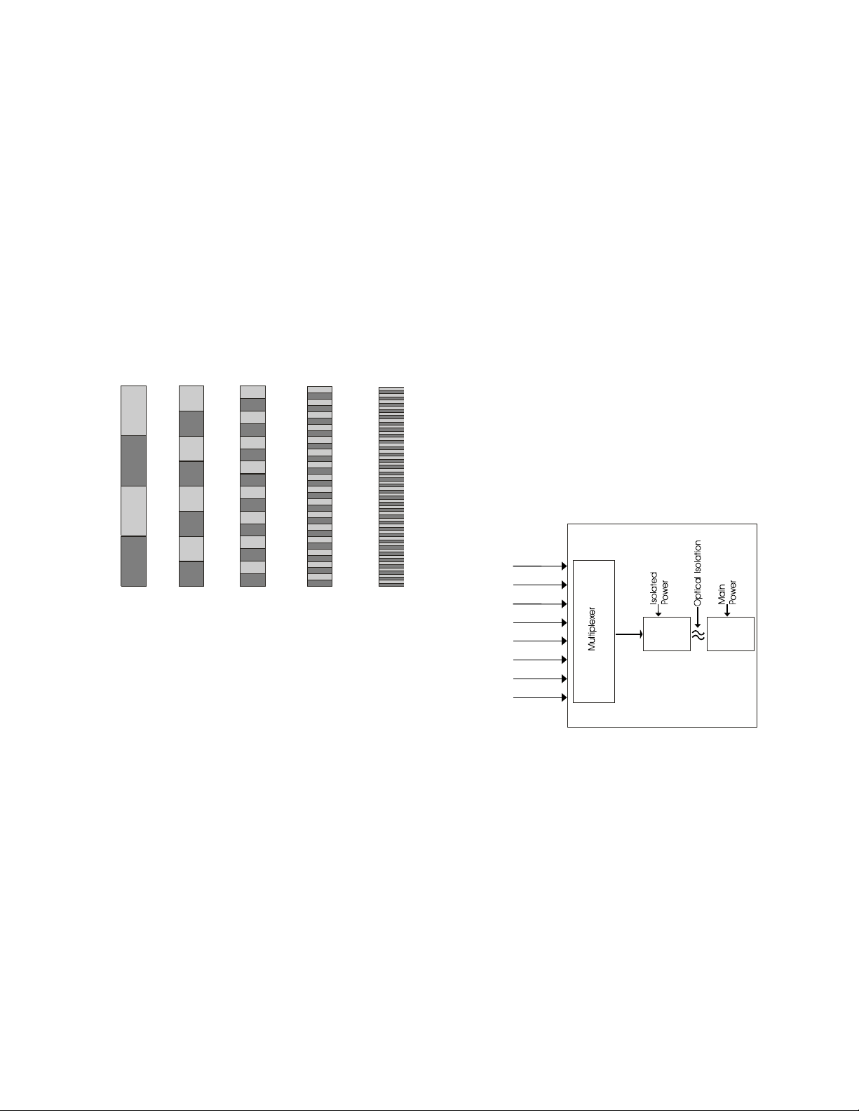
Resolution is the number of significant
bits of information the A/D converter uses to
express the value of the measured input. A
12-bit A/D converter uses 12 bits of information,
meaning the entire range is covered by a number
between 0 and (2
A/D expresses the same range as a number
between 0 and 16,383. In other words, the more
bits used, the finer the increment. In general
terms, the higher the resolution, the better.
(12)
-1) or 0 to 4095. A 14-bit
Range
The analog input range is the minimum
and maximum voltage, or current level,
measured by the A/C converter. Typical ranges
are 0 to 5 volts, 0 to 10 volts, +/- 5 volts, +/- 10
volts, and 4 to 20 mA.
You should try to match the input range
to the range of the signal that you are measuring.
Multiplexing
Analog to digital converter devices are
typically quite expensive. In order to keep the
cost per channel of analog inputs down, a
multiplexer is commonly used.
2 3 4 5 6
Bits of Resolution
Accuracy
Accuracy is expressed as the worst case
deviation from the “ideal value” across the entire
input range. For example, for a 0 to 5V input
range and a 12-bit A/D module, a 2.0 volt input
should yield a value equal to 1638 (0.4 x 4096).
If it returns a value of 1636, and this is the worst
case error across the entire range of 0 to 5V, the
accuracy is 12 bits +/- 2 counts.
Analog
inputs
A/D
Converter
Bus
Interface
Converter Module
A multiplexer switches one analog input
at a time into the A/D converter. Each input is
converted in sequence. The trade off is reduced
sampling rate for a particular channel versus
reduced cost per channel measured. In most
industrial applications, the conversion rate is so
fast in relation to the rate of change in the
measured value, that sampling rate is not a
factor.
Optimation, Inc.
(256)883-3050
www.optimate.com
12
Page 13
OptiLogic Series
Single Ended Inputs
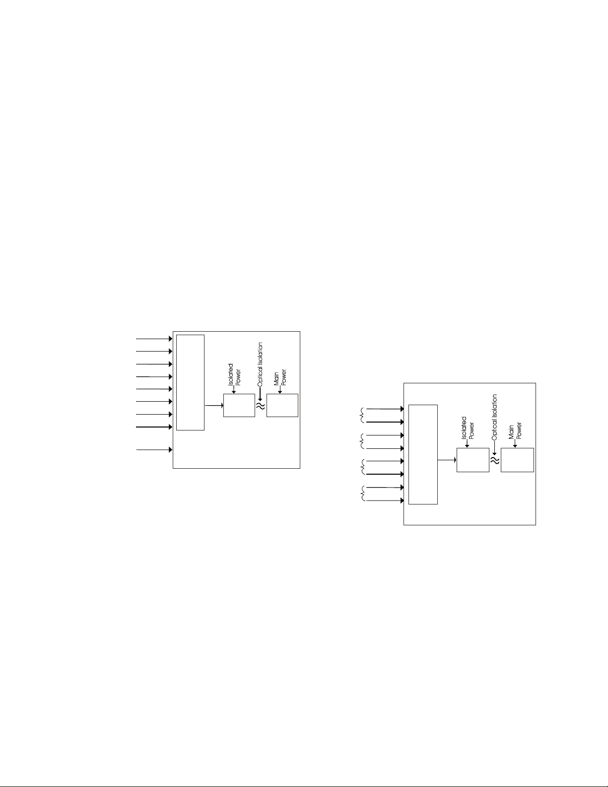
Single ended inputs are all referenced to
the same ground point. In many applications,
single ended inputs produce significant
advantages. Single ended inputs require only
one ground connection and one signal input per
measured value. The result is reduced wiring
costs along with the reduced cost per channel on
the analog input module.
In order to use single ended inputs, the
ground connection must be very good. The
measurement devices must also be capable of
being referenced to a common ground.
Differential Inputs
There are cases when the individual
analog inputs cannot be connected to a common
ground. In those cases, a differential input A/D
converter should be used.
With a differential analog input, both a
positive and negative signal line must be
connected for each signal. The analog input
module then measures the difference between
the positive and negative. The effect of one
channel’s signal on another channel’s signal
should be as little as possible. That relationship
of the effect on the measured value of one
channel to the value input on a second channel is
called “common mode”. The higher the
“common mode rejection ratio (CMRR)” the
better.
Analog
inputs
Common
ground
A/D
Converter
Bus
Interface
Converter Module
Analog
inputs
+
-
+
-
+
-
+
-
A/D
Converter
Bus
Interface
Converter Module
Optimation, Inc.
(256)883-3050 13
www.optimate.com
Page 14

www.optimate.com
7
1A (resistive)/point
8
Outputs
Output Type
Contact voltage rating
Contact rating
Contact type
Minimum load
Contact arrangement
Mechanical life
OL2104 Relay Output Module
4
Mechanical relay
0 - 24 VDC
0 - 120 VAC
@24 VDC, 1A/point
@120 VAC, 1A/point
Form A (SPST)
10 mA
4 isolated normally
open contact relays
10,000,000 operations
per relay (at no load)
Card Cage Power
Required
Contact resistance
Status Indicators
Terminal Strip
Terminal Screws
Maximum terminal
wire gauge
Terminal block torque
Required Temperature
rating of field installed
conductors
215 mA
0.1 ohm (initial)
Logic Side LED
Plug In (removable)
Slotted
max)
18 AWG (use copper
conductors)
2.2 lb-in
60°C/75°C
(0.1î blade
Electrical life
Type
Optimation, Inc. (256)883-3050 14
2 3
O
L
8
7
6
5
4
3
2
1
0 1
2104
100,000 operations per
relay (at full load)
Weight
Subtype
Inductive load
isolation
O
U
T
Diode protectio
n
Output module
From
O
ic
ptiLog
processo
r
L3
L2
1.6 oz (58 g)
1
8
6
5
4
3
2
1
Terminal
1
Out0 NO 5
2
Out0 C 6
Terminal
Out2 NO
Out2 C
L1
L0
5-30VDC
5-132VAC
Page 15
www.optimate.com
9
Outputs
Output type
Contact voltage rating
Contact rating
Contact type
Minimum load
Contact arrangement
Mechanical life
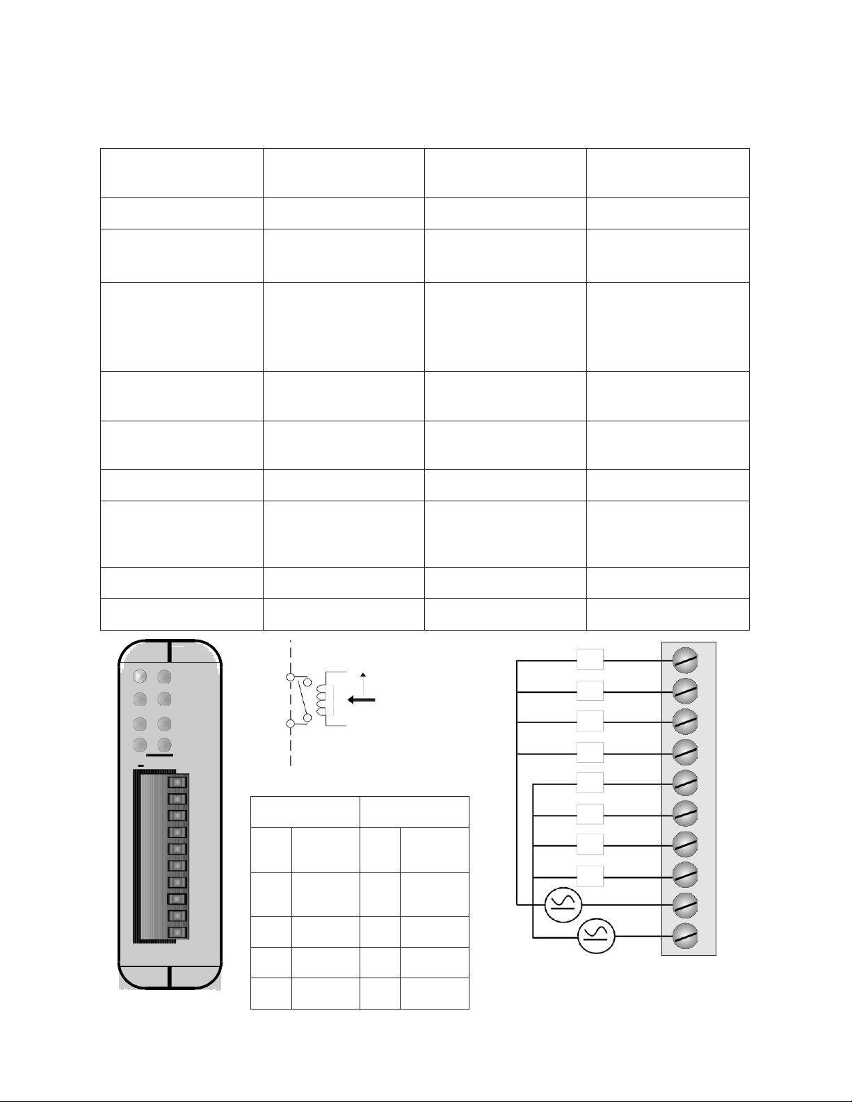
OL2108 Relay Output Module
8
Mechanical relay
0 - 24 VDC
0 - 120 VAC
1A (resistive)/point
@24 VDC, 1A/point
@120 VAC, 1A/point
Form A (SPST)
10 mA
4 relays per common
10,000,000 operations
per relay (at no load)
Card Cage Power
required
Contact resistance
Status Indicators
Terminal Strip
Terminal Screws
Maximum Terminal
Wire Gauge
Terminal block torque
Required Temperature
rating of field installed
conductors
375 mA
0.1 ohm (initial)
Logic Side LED
Plug In (removable)
Slotted
max.)
18 AWG (use copper
conductors)
2.2 lb-in
60°C/75°C
(0.1î blade
Electrical life
Type
Optimation, Inc. (256)883-3050 15
0 1
2 3
4 5
6 7
O
L
2108
10
9
8
7
6
5
4
3
2
1
100,000 operations per
Weight
Subtype
To LED
Fro
m
O
processor
ic
ptiLog
Terminal
6
Out 3
7
Out 4
isolation
O
U
T
module internal
circuit
Terminal
1
Common
Out 0-3
2
Common
Out 4-7
2.1 oz (58g)
1
L7
L6
L5
L4
L3
L2
L1
L0
10
9
8
7
6
5
4
3
2
1
3
Out 0
8
Out 5
4
Out 1
5
Out 2 10 Out 7
9
Out 6
5-30VDC
5-132VAC
Connection diagram
Page 16
OptiLogic Series
circuit
optical
5-40VDC
OL2109 DC Sinking Output Module
Outputs 8
Output Type
NPN open collector
transistor
Card Cage Power
required
140 mA
Status indicators Logic side LED
Voltage Rating 0 - 40VDC Peak Voltage 80VDC
.75V @ 100mA
On voltage drop
Terminal strip Plug In (removable)
.95V @ 300mA
Commons 2 (connected internally) Terminal screw
Maximum continuous
load current
Maximum surge
current
300 mA
1.0A for 5 seconds
Maximum terminal
wire gauge
Required Temperature
rating of field installed
conductors
Slotted (0.1” blade
max)
18 AWG (use copper
conductors)
60C/75C
Weight 1.1 oz (30 g) Terminal block torque 2.2 lb-in
Type 9 Subtype 2
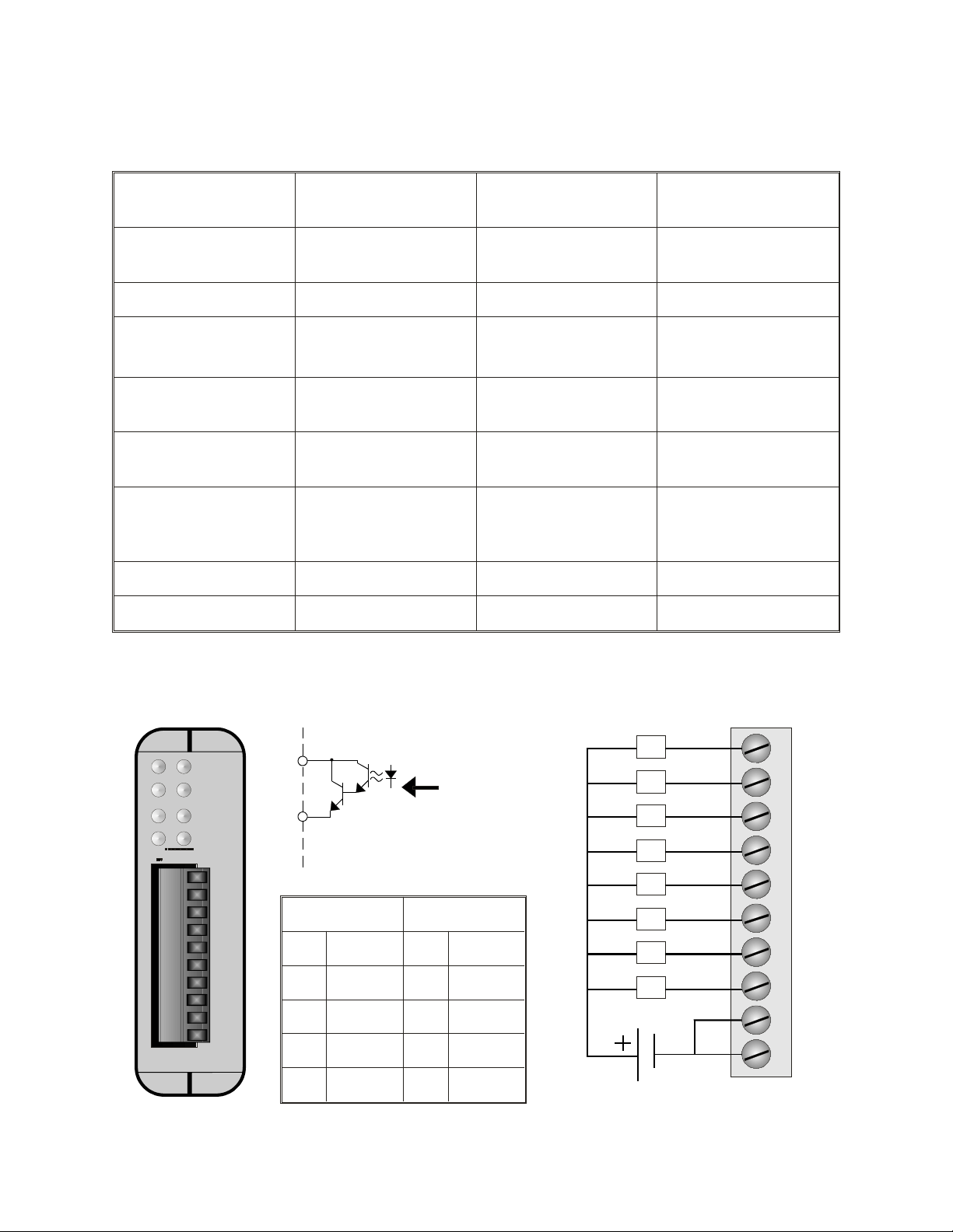
The OL2109 Transistor Output module provides eight optically isolated transistor outputs which can be used for
switching small DC loads. Individual LED indicators provide visual feedback of output state.
OO
L
10
9
8
7
6
5
4
3
2
1
0
2
4
6
2109
isolation
1
O
3
U
5
T
7
module internal
From
OptiLogic
processor
Terminal Terminal
1 Common 6 Out 3
2 Common 7 Out 4
3 Out 0 8 Out 5
4 Out 1 9 Out 6
L7
L6
L5
L4
L3
L2
L1
L0
10
9
8
7
6
5
4
3
2
1
5 Out 2 10 Out 7
Connection diagram
Optimation, Inc.
(256)883-3050
www.optimate.com
16
Page 17
OptiLogic Series
15-132VAC
circuit
optical
OL2111 AC Solid State Relay Module
Outputs 8
Card Cage Power
required
120 mA
Output Type SSR (Trice) Commons 2 (connected internally)
Voltage Rating 12 - 132 VAC Status indicators Logic side LED
Max. load current .5A/point @ 120VAC
Min. load current 10mA Terminal Strip Plug In (removable)
On state voltage drop 1V (typical) Terminal screws
Peak one cycle surge
current
15A
Maximum terminal
wire gauge
Slotted (0.1” blade
max.)
18 AWG (use copper
conductors)
Required Temperature
AC frequency 47 - 63 Hz
rating of field installed
60C/75C
conductors
Weight 1.3oz (38g) Terminal block torque 2.2 lb-in
Type 9 Subtype 3
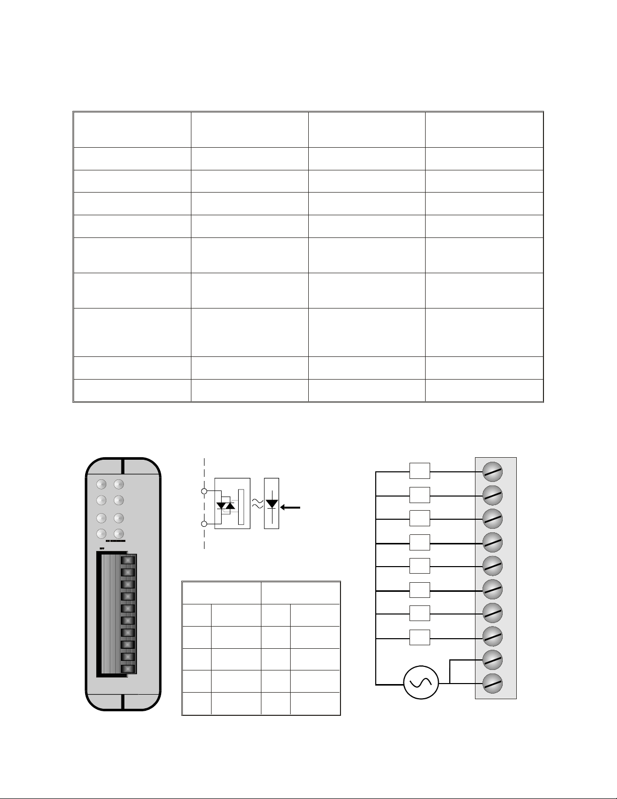
The OL2111 Solid State Relay module provides eight (8) solid state relay outputs. This module is ideally suited for
switching small AC loads. As a solid state device, switch wear will not be a factor. Each output is optocoupled for
system isolation. Individual LED indicators provide visual feedback indicating the state that each relay is being driven.
0
2 3
isolation
1
O
From
OptiLogic
processor
L7
L6
10
9
U
4
OO
6
L
2111
10
9
8
7
6
5
4
3
2
1
5
T
7
module internal
L5
L4
L3
Terminal Terminal
1 Common 6 Out 3
2 Common 7 Out 4
3 Out 0 8 Out 5
4 Out 1 9 Out 6
L2
L1
L0
8
7
6
5
4
3
2
1
5 Out 2 10 Out 7
Connection diagram
Optimation, Inc.
(256)883-3050 17
www.optimate.com
Page 18
OptiLogic Series
OL2201 Digital Input Simulator Module
Inputs 8
Card Cage Power
Required
60mA
Input Type Toggle Switch Status Indicators Logic side LED
Weight 1.1 oz (30 g)
Type 1 Subtype 3
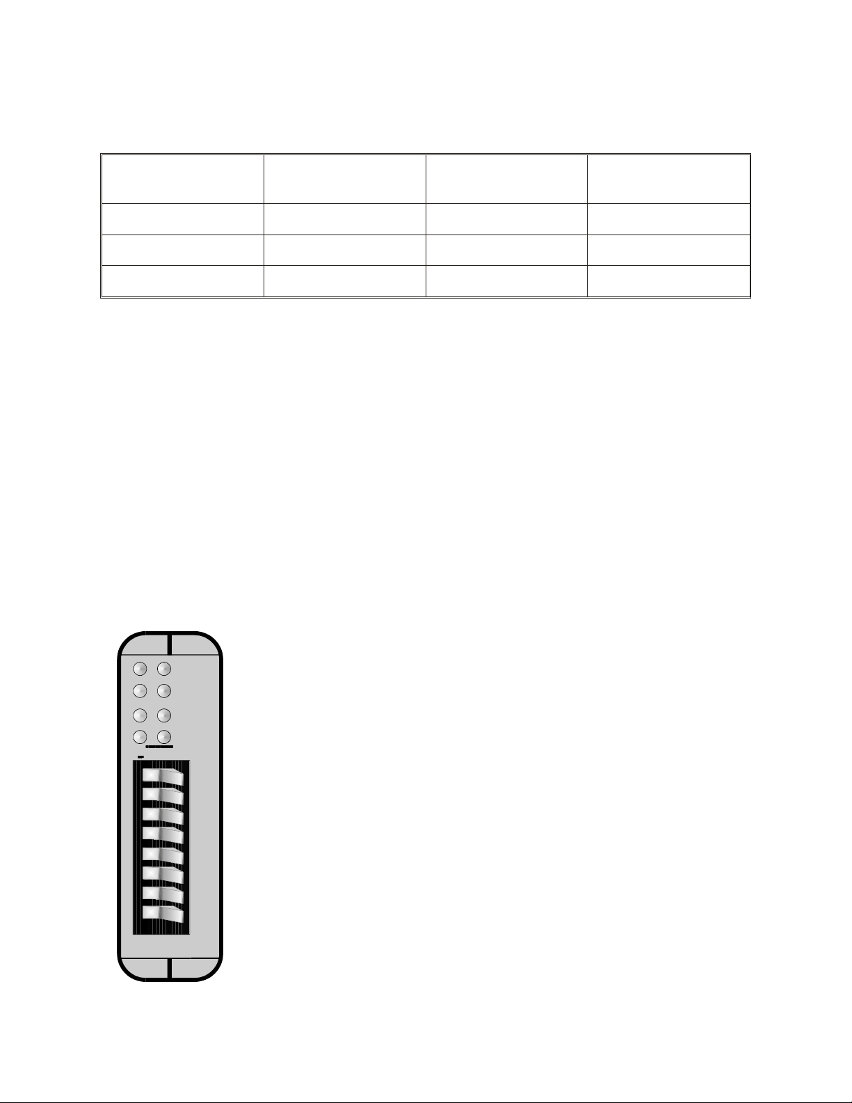
The OL2201 Digital Input Simulator Module is designed to be an aid to program development.
Use the OL2201 to simulate real world inputs during your design and debug process. The
OL2201 enables the program developer to cause a change in input status at will to simulate a
system action. In doing so, you are able to see the program’s response. Use of the OL2201 is an
aid in the process of thoroughly testing and debugging a system prior to “going live” with real
hardware.
When it becomes time to move to real hardware, replace the OL2201 with the appropriate digital
input module. The logic of your program will remain the same.
1
0
3
2
I
4
5
N
7
6
OO
L
2201
Optimation, Inc.
(256)883-3050
www.optimate.com
18
Page 19
OptiLogic Series
circuit
optical
10-30V AC or DC
IN3
OL2205 AC/DC Input Module
Inputs 4
Card Cage Power
Required
60mA
Input Type AC Optocoupled Status Indicators Logic Side LED
Voltage Range 10-30 V AC or DC Input Impedence 2.7K
Min. On Current (per
point)
Max. On Current (per
point)
Max. Terminal wire
gauge
3.3 mA Inputs
11 mA Terminal Strip Plug In (removable)
Terminal Screws
18 AWG (use copper
conductors)
Required Temperature
rating of field installed
conductors
DC sinking or sourcing
/ or AC
Slotted (0.1” blade
max.)
60C/75C
Weight 1.2 oz (34g) Terminal block torque 2.2 lb-in
Type 5 Subtype 1
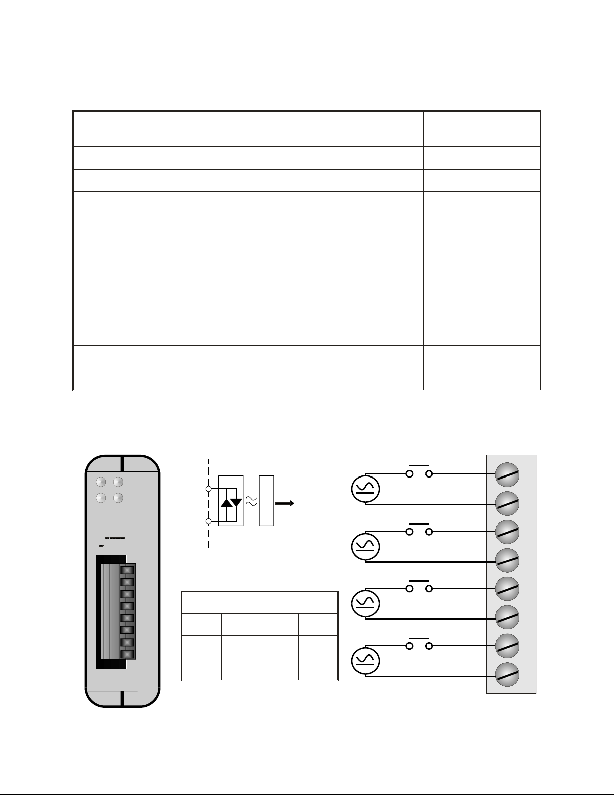
The OL2205 Digital Input module senses up to four (4) AC or DC input signals. All inputs are individually
optocoupled for isolation. Inputs are also individually isolated from each other by separate terminal connections.
Filtering is provided for zero crossover. Individual LED indicators provide visual feedback of current status.
0
1
3
2
I
N
OO
L
2205
8
7
6
5
4
3
2
1
Optimation, Inc.
isolation
module internal
To
OptiLogic
processor
Terminal Terminal
1 In 0 5 In 2
2 In 0 6 In 2
3 In 1 7 In 3
(256)883-3050 19
www.optimate.com
IN2
IN1
IN0
8
7
6
5
4
3
2
1
Page 20
OptiLogic Series
Sourcing
10-30VDC
circuit
optical
OL2208 DC Digital Input Module
Inputs 8
Card Cage Power
required
60mA
Input Type DC Optocoupled Status Indicators Logic side LED
Voltage Range 10 - 30 VDC Input Impedance 2.7K
Min. On Current (per
point)
3.3 mA
Max. On Current (per
point)
11 mA
Commons 2 Terminal Strip Plug In (removable)
Max. Terminal wire
gauge
18 AWG (use copper
conductors)
Terminal screw
Slotted (0.1” blade
max.)
Required Temperature
rating of field installed
60C/75C
conductors
Weight 1.2 oz (34g) Terminal block torque 2.2 lb-oz
Type 1 Subtype 1
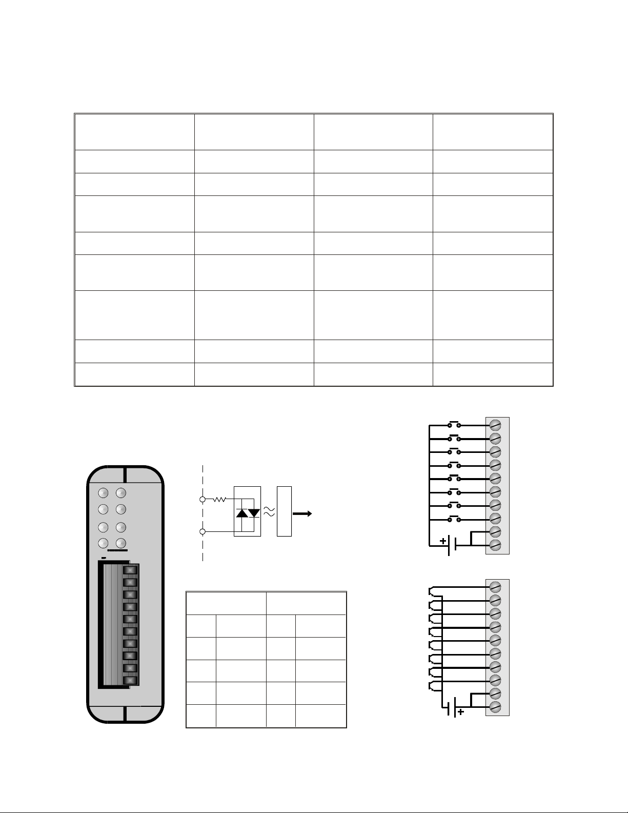
The OL2208 DC Digital Input module can be used in either sourcing or
sinking application (all 8 inputs must be used in the same manner). Each
input is optocoupled to provide system isolation. Individual LED
indicators provide a visual feedback of current status.
isolation
1
0
3
2
To
OptiLogic
processor
I
4
5
N
7
OO
6
L
2208
10
9
8
7
6
5
4
3
2
1
module internal
Terminal Terminal
1 Common 6 In 3
2 Common 7 In 4
3 In 0 8 In 5
4 In 1 9 In 6
IN7
IN6
IN5
IN4
IN3
IN2
IN1
IN0
10-30VDC
Sinking
IN7
IN6
IN5
IN4
IN3
IN2
IN1
IN0
10
9
8
7
6
5
4
3
2
1
10
9
8
7
6
5
4
3
2
1
5 In 2 10 In 7
Connection diagram
Optimation, Inc.
(256)883-3050
www.optimate.com
20
Page 21

OptiLogic Series
80-132VAC
IN7
circuit
optical
OL2211 AC Digital Input Module
Inputs 8
Card Cage Power
Required
60 mA
Input Type AC Optocoupled Status Indicators Logic side LED
Voltage Range 80 - 132 VAC Input Impedance 47K
Min. On Current (per
point)
Max. On Current (per
point)
Max terminal wire
gauge
1.7 mA Commons 2 (connected internally)
2.8 mA Terminal Strip Plug In (removable)
Slotted (0.1” blade
max.)
60C/75C
18 AWG (use copper
conductors
Terminal Screws
Required Temperature
rating of field installed
conductors
Weight 1.3 oz (38g) Terminal block torque 2.2 lb-in
Type 1 Subtype 2
The OL2211 AC Digital input module senses up to eight (8) AC input signals. All inputs are individually
optocoupled for isolation. Filtering is provided for zero crossover. Individual LED indicators provide visual
feedback of current status.
0
2
4 5
OO
L
10
9
8
7
6
5
4
3
2
1
6
2211
isolation
1
3
I
To
OptiLogic
processor
IN6
IN5
N
7
module internal
IN4
IN3
Terminal Terminal
1 Common 6 In 3
2 Common 7 In 4
3 In 0 8 In 5
4 In 1 9 In 6
IN2
IN1
IN0
10
9
8
7
6
5
4
3
2
1
5 In 2 10 In 7
Optimation, Inc.
(256)883-3050 21
www.optimate.com
Page 22
OptiLogic Series
circuit
optical
10-30VDC
IN7
OL2252 Dual High Speed Pulse Counter
Inputs (all) 8
Card Cage Power
Required
100 mA
Pulse Inputs 2 Status Indicators Logic side LED
Input Voltage 10 - 30 VDC Input Impedance 2.7K ohms
Input frequency (on
pulse inputs)
Min. On Current (per
point)
Max. On Current (per
point)
Max terminal wire
gauge
15 KHz maximum Commons 2
3.3 mA Terminal Strip Plug In (removable)
11 mA Terminal Screws
Slotted (0.1” blade
max.)
Required Temperature
18 AWG
rating
of field installed
60C/75C
conductors
Weight 1.2 oz (34g) Terminal block torque 2.2 lb-in
Type 80 Subtype 1
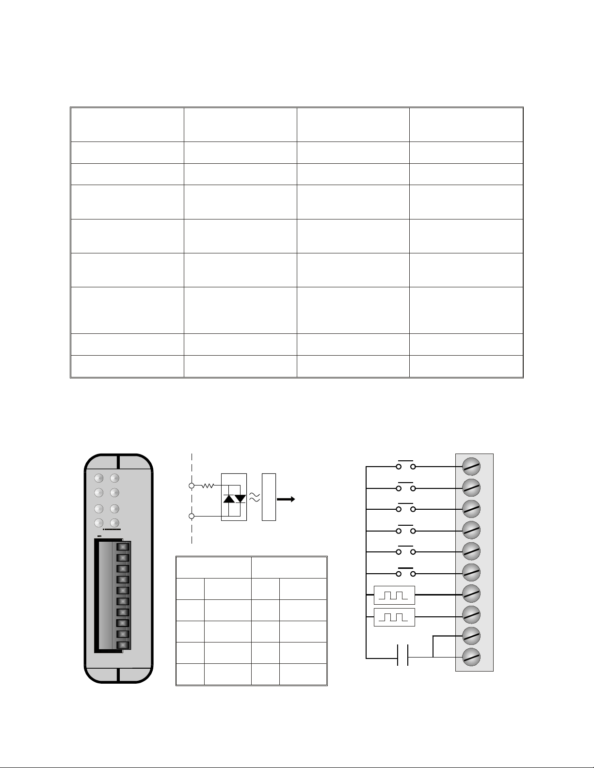
The OL2252 module provides two independent high speed pulse counter inputs. Each input counter will accurately
count pulse inputs up to 15KHz. Inputs may be sourcing or sinking type There are a number of operating options
available with the OL2252. The six remaining inputs can be used as predefined control signals or as general
purpose inputs. These options are detailed in the following pages.
1
0
4 5
OO
L
10
9
8
7
6
5
4
3
2
1
2
6
2252
P
U
L
3
S
E
I
7
N
Optimation, Inc.
isolation
To
OptiLogic
processor
module internal
Terminal Terminal
1 Common 6 Reset 2
2 Common 7 Enable 1
3 Pulse 1 8 Enable 2
4 Pulse 2 9 In 6
5 Reset 1 10 In 7
(256)883-3050
www.optimate.com
IN6
EN 2
EN 1
RESET 2
RESET 1
Pulse 2
Pulse 1
10
9
8
7
6
5
4
3
2
1
22
Page 23

OptiLogic Series
OL2252 Dual Pulse Counter cont’d
The OL2252 Dual Pulse input module is
designed to provide two independent pulse
counting inputs. Each input is independent of
the other. There are also a number of
configuration options available.
The following is a list of the input
connections.
Terminal Label Description
1 Common
2 Common
3 Pulse 1
4 Pulse 2
5 Reset 1
6 Reset 2
7 Enable 1
8 Enable 2
Sourcing or sinking return line
Sourcing or sinking return line
Square wave input up to 15KHz
Square wave input up to 15KHz
If configured as “reset” input ,
will clear the pulse 1 count
when activated. If not
configured as
be used as a general purpose
input.
If configured as “reset” input ,
will clear the pulse 2 count
when activated. If not
configured as
be used as a general purpose
input.
If configured as an “enable”
input, enables the pulse 1
counter when active. If not
configured as an
can be used as a general
purpose input.
If configured as an “enable”
input, enables the pulse 2
counter when active. If not
configured as an
can be used as a general
purpose input.
“reset” input, can
“reset” input, can
“enable” input,
“enable” input,
Theory of Operation
The OL2252 Pulse Counter has two
independent pulse counter inputs. These pulse
counter inputs will accurately count pulses
between 0 and 15KHz.
All counts begin at zero and count up to
the maximum number the counter can hold
(4,294,967,295). If the count should ever get
that high, it will roll over to zero.
In order to count, the count input must be
enabled. A message with an enable must come
from the host PC. The module can also be set up
to use the local hardware input enable (in
addition to the enable message). If you are using
Think & Do, all of this set up and signaling is
part of your Think & Do program. If you are
using Visual Basic or C, please refer to the
interface software manual.
The count can be reset to 0 at any time.
Again there is both a reset message that can be
sent from the PC and an optional hardware reset
signal.
Whether the hardware “reset” and
“enable” are used is set up from the host PC via a
configuration message. Think & Do will take
care of the details. Visual Basic and C users can
also easily send this message as part ot their
application program.
9 Input 6
10 Input 7
Optimation, Inc.
General purpose input
General purpose input
(256)883-3050 23
www.optimate.com
Page 24
OptiLogic Series
OL2252 Pulse Input cont’d
Input Signal
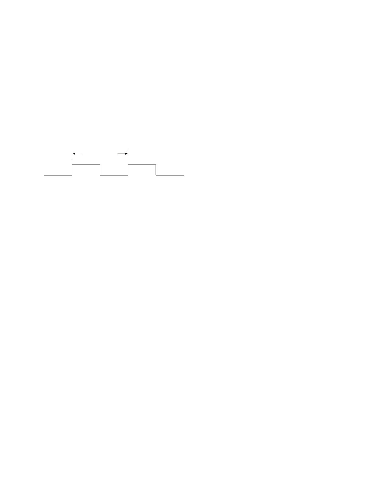
The input pulse train is a repetitive
square wave input that looks something like the
following.
1 count
If you know the maximum frequency of
the pulse train, you can configure the pulse
counter to count pulse up to that pulse rate. In
doing so, the counter will consider anything
above the maximum rate that you have defined
to be noise and will ignore it.
Optimation, Inc.
(256)883-3050
www.optimate.com
24
Page 25

OptiLogic Series
OL2258 High Speed Pulse Counter
Inputs (all) 4
Pulse Inputs 2 Status Indicators Logic side LED
Input signal type
Input frequency (on
pulse inputs)
Min. Input On Voltage
(or differential)
Max. Input Off Voltage
(or differential)
Max. Input voltage 28V
Outputs 2
Sinking, sourcing or
differential
80/160 KHz
maximum
4.00V Frequency data
3.00V Counting Modes
Card Cage Power
Required
Input Impedance 2.0K ohms nominal
Count value 32 bit signed integer
Max terminal wire
gauge
100 mA
16 bit signed integer
(Configurable for 1
second or 200 mS count)
Pulse & Direction
Up/Down Count
Quadrature
18 AWG (use copper
conductors)
Output Type Open collector Terminal Strip Plug In (removable)
Max Output current 300 mA Terminal Screws Slotted (0.1” blade max.)
Required Temperature
Output Voltage range 0 - 40VDC
Weight 1.24 oz (35g) Terminal block torque 2.2 lb-in
Type 82 Subtype 1
rating of field installed
conductors
60C/75C
The OptiLogic OL2258 High Speed Pulse Counter module provides for direct pulse
counting for a variety of high speed pulse interface applications. Typical applications include
motion control, metering and velocity measurement. The OL2258 contains on board intelligence
necessary for processing and counting pulse information as well as automatically triggering control
outputs.
The OL2258 can be configured configured to operate in one of three pulse counting modes.
These modes are 1) Pulse & Direction, 2)Up/Down Count and 3) Quadrature . Pulse & Direction
and Up/Down count will operate at up to 80KHz input pulse rates. Quadrature inputs count each
quadrature state transitions at up to 160 KHz. Additionally, the OL2258 will return frequency
information.
Optimation, Inc.
(256)883-3050 25
www.optimate.com
Page 26
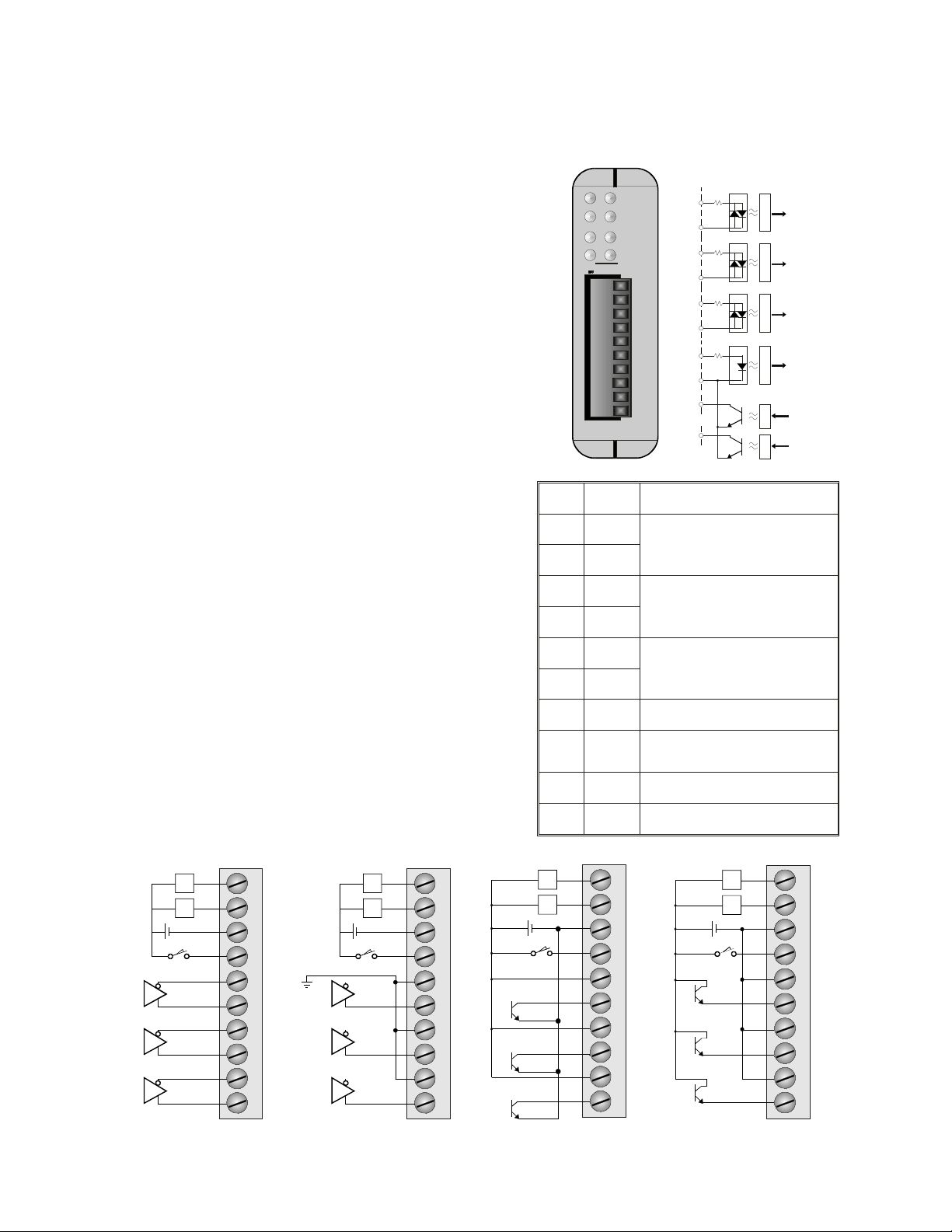
OptiLogic Series
Differential Drive Interface
OL2258 Interface
Sinking Encoder Interface
Sourcing Encoder Interface
Differential Drive Interface
OL2258 High Speed Pulse Counter cont’d
Interfacing the OL2258
The OL2258 High Speed Pulse counter is designed
to interface to a variety of standard pulse encoder devices.
The electrical interface is shown on the right.
Differential, sourcing, or sinking type inputs can be
interfaced to the OL2258. The figures across the bottom of
this page illustrate connections for each type of encoder.
General Overview
The OL2258 is configurable. It can be used with
pulse & direction, up/down count or quadrature type
pulse encoders. These signals may come from shaft
encoders, flow meters or any other signal source that
produces a pulse train output. When operating, the
OL2258 maintains a current cummulative count as a 32
bit integer value. It also makes available frequency
snapshot data as the most recent count over either 1
second or 200 milliseconds. The Z and LS inputs can be
used to automatically reset the count to a user defined
value. Each transistor output can be configured to turn
on when the count value is within its related count range.
1
2
3
4
5
6
7
8
9
10
Outs
OO
L
10
9
8
7
6
5
4
3
2
1
A
Z LS
1
2258
B
P
U
L
S
E
2
I
N
Term Label Description
1 A1
2 A2
3 B1
4 B2
5 Z1
Pulse input A(quadrature)/
Pulse input (pulse & direction)/
Up pulse (up/down count)
Pulse input B(quadrature)/
Direction (pulse & direction)/
Down pulse (up/down count)
Z input (optional)
6 Z2
A
B
Z
LS
Out1
Out2
(Positive differential)
L2
L1
LS
Z
B
A
Optimation, Inc.
10
9
8
7
6
5
4
3
2
1
encoder ground
Z
B
A
(Bipolar differential)
L2
L1
LS
10
9
8
7
6
5
4
3
2
1
Z
B
A
(256)883-3050
www.optimate.com
7 LS
8 Com
9 Out1
10 Out2
L2
L1
LS
Limit switch input (optional)
Common for limit switch and
two outputs
Open collector output 1
Open collector output 2
10
9
8
7
6
5
4
3
2
1
L2
L1
LS
Z
B
A
10
9
8
7
6
5
4
3
2
1
26
Page 27

OptiLogic Series
Quadrature Count
Count
17-126-235-34453627180
OL2258 High Speed Pulse Counter cont’d
Pulse and Direction
In this configuration, pulses are input to
“A”. The counter direction is controlled by input
“B”. The operation is illustrated below.
Pulse & Direction Count
Pulse (A)
Direction (B)
Count
1 2 3 4 5 4 3
2 1 0
1 2
Quadrature Encoder Input
The counting process for quadrature type
encoding is determined by the phase angle
between input A and input B. If A leads B, the
counter increments. If B leads A, the counter
decrements. The count is incremented or
decremented on each pulse transition as shown
below.
Z and LS Presetting
The count can be preset to a value that
you define based on either or both inputs LS and
Z. It can also be forced to a preset value on
command via a message.
Through the configuration message, the
counter can be set up to force a preset value
when Z is active, LS is active, both Z and LS are
active or on software command.
Output Control
The two open collector outputs can each
be progammed to trigger within a programmable
(via an ethernet message) count range. This
range can be changed at any time via a “Send
Output Range” message, effectively providing
and unlimited number of ranges, under user
program control.
Outputs will trigger within immediately,
when the count enters the related range.
Pulse (A)
Pulse (B)
Up/Down Count
For this type of configuration, the count
increments on pulses input to “A” and
decrements on pulses input to “B”. This is
illustrated in the figure below.
Up/Down Count
Up Pulse (A)
Down Pulse (B)
Count
Optimation, Inc.
1 2 3 4 5 4 3
2 1 0
01 1
(256)883-3050 27
www.optimate.com
Frequency Measurement
Frequency data can be read back as a 16
bit signed integer value. The value will
correspond to the most recent 1 second or 200
millisecond (configurable) pulse count.
Page 28
OptiLogic Series
OL2304 Four Channel Voltage Output
Outputs 4
0-5V, 0-10V, +/-5V, +/-10V
Output Ranges
Resolution 12 bit (1 in 4096) Output current +/-5mA
Output type
Offset calibration
error
Nonlinearity +/- 1 count Terminal strip Plug In (removable)
Load impedence 2Kohm mimimum Terminal screws
Terminal block torque 2.2 lb-in
Type 25 Subtype 1
(individual channel
configurable)
Single ended, 1
common
+/-8 counts @ +/-10V
+/-16 counts @ +/-5V
+/-16 counts @ 0-10V
+/- 32 counts @ 0-5V
Card Cage Power
required
External Power
required
Short circuit current +/-15mA
Max terminal wire
gauge
Required Temperature
rating of field installed
conductors
700mA
none
18 AWG (use copper
conductors)
Slotted (0.1” blade
max)
60C/75C
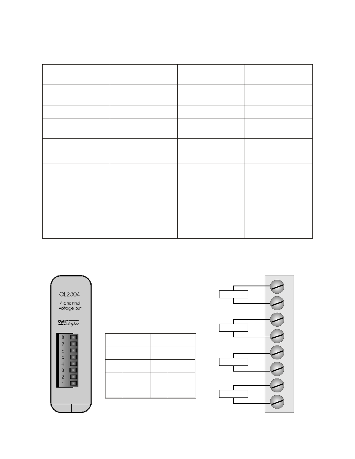
The OL2304 analog output module is range configurable, on a channel by channel basis, to any of four common
output ranges. Each channel can be configured, via software for either 0-5V, 0-10V, +/-5V or +/-10V ranges. The
module generates its own isolated output power supply, eliminating any need for an outside source.
Terminal Terminal
1 Common 5 Common
2 Out 1 6 Out 3
3 Common 7 Common
4 Out 2 8 Out 4
+
Channel 4
-
+
Channel 3
-
+
Channel 2
-
+
Channel 1
-
8
7
6
5
4
3
2
1
Optimation, Inc.
(256)883-3050
www.optimate.com
28
Page 29
OptiLogic Series
OL2408 Analog Voltage Input Module
Inputs 8 Power required 700mA
Input Type
Resolution 14 bit (1 in 16384)
Input Impedance 10 MOhm
Maximum Voltage
Input
0-5 VDC or
0-10VDC
+/- 15VDC
Conversion Type Successive approximation
Full Scale Calibration
Error
Offset Calibration error
Max. Terminal wire
gauge
+/- 15 counts max.
+/- 5 counts typical
+/- 2 counts max.
18 AWG (use copper
conductors)
Linearity error +/- 1.25 count max Terminal Strip Plug In (removable)
Input stability +/- 2 counts Terminal Screws Slotted (0.1” blade max.)
Terminal block
torque
2.2 lb-in
Required Temperature
rating of field installed
conductors
60C/75C
Type 17 Subtype 1
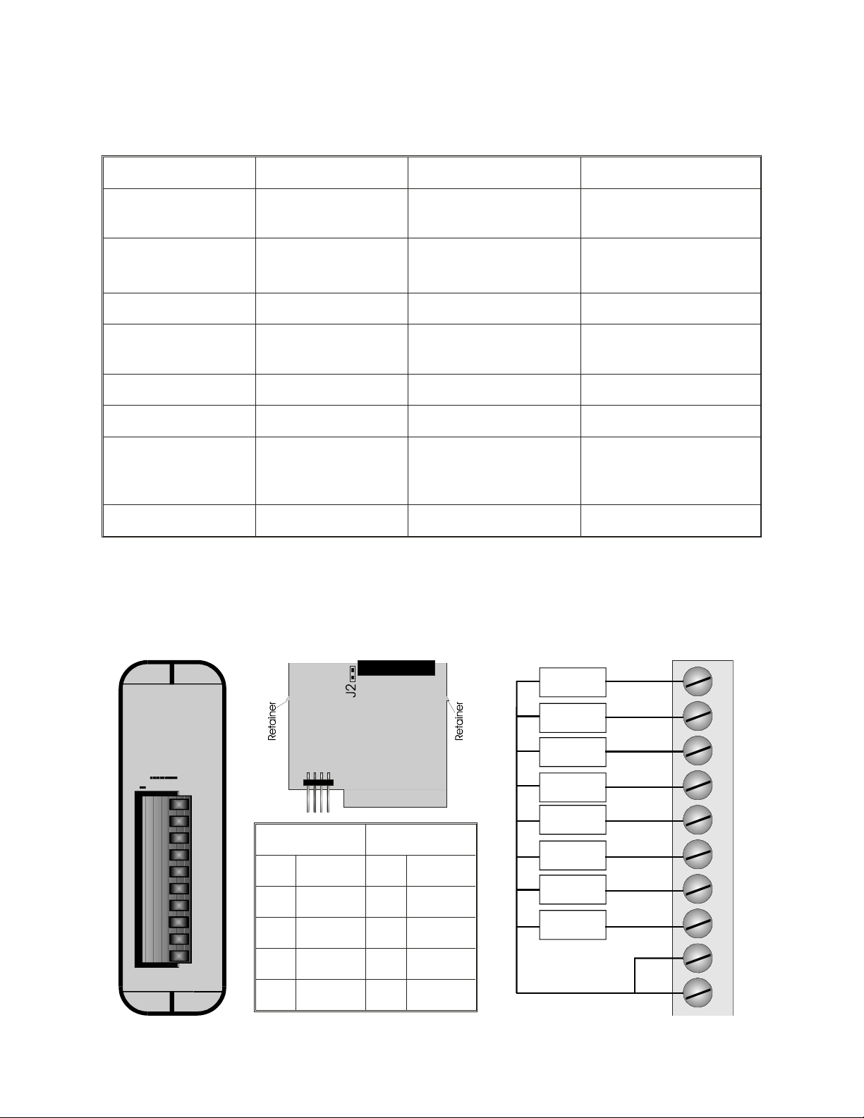
The OL2408 comes set up for 0-5VDC input range. If you need 0-10VDC input range, you must remove the plastic
module cover by lifting the board latches over the retainer hooks on the PC board. Then, place the jumper on both
pins of J2 and replace the plastic module cover. To change back to 0-5VDC range, repeat the process and remove
the jumper. Having the cover over the range selector jumper ensures that it will not be inadvertantly changed.
Analog
Voltage
Input
O
L
2408
10
9
8
7
6
5
4
3
2
1
Optimation, Inc.
Terminal Terminal
1 Common 6 Channel 4
2 Common 7 Channel 5
3 Channel 1 8 Channel 6
4 Channel 2 9 Channel 7
5 Channel 3 10 Channel 8
(256)883-3050 29
www.optimate.com
0-5 VDC
or 0-10 VDC
0-5 VDC
or 0-10 VDC
0-5 VDC
or 0-10 VDC
0-5 VDC
or 0-10 VDC
0-5 VDC
or 0-10 VDC
0-5 VDC
or 0-10 VDC
0-5 VDC
or 0-10 VDC
0-5 VDC
or 0-10 VDC
10
9
8
7
6
5
4
3
2
1
Page 30
OptiLogic Series
OL2418 Analog Current Input Module
Inputs 8
Input Type 4 - 20 mA Conversion Type
Resolution 14 bit (1 in 16384)
Input Impedence 250 ohm +/- 0.05%
Card Cage Power
Required
Full Scale Calibration
Error
Offset Calibration Error
700mA
Successive
approximation
+/- 15 counts max.
+/- 5 counts typical
+/- 2 counts max.
Power Isolation Transformer Signal Isolation Optical
Max. Terminal Wire
Gauge
18 AWG (use copper
conductors)
Linearity error +/- 1.25 counts Terminal Strip Plug In (removable)
Input Stability +/- 2 counts Terminal Screws Slotted (0.1” blade max.)
Terminal block
torque
2.2 lb-in
Required Temperature
rating of field installed
conductors
60C/75C
Type 18 Subtype 2
O
L
2418
8 channel
analog
current in
10
9
8
7
6
5
4
3
2
1
Optimation, Inc.
optical
isolation
To
4-20 mA
analog current
input module
OptiLogic
processor
Terminal Terminal
1 Common 6 Channel 4
2 Common 7 Channel 5
3 Channel 1 8 Channel 6
4 Channel 2 9 Channel 7
(256)883-3050
www.optimate.com
4-20 mA
4-20 mA
4-20 mA
4-20 mA
4-20 mA
4-20 mA
4-20 mA
4-20 mA
10
9
8
7
6
5
4
3
2
1
30
Page 31

OptiLogic Series
OL2602 Dual RS232 Module
Communication Ports 2
Card Cage Power
Required
110 mA
Type RS232C Status Indicators LEDs for TX and RX
1200, 2400, 4800,
Baud Rates
9600, 19,200
System limitations *See below
(selectable)
Parity Even, odd or none
Max. Terminal Wire
gauge
18 AWG (use copper
conductors)
Data bits 7 or 8 Terminal Strip Plug In (removable)
Transmit buffer 48 bytes Terminal Screws
Required Temperature
Receive buffer 48 bytes
rating of field installed
conductors
Slotted (0.1” blade
maximum)
60C/75C
Weight 1 oz (29g) Terminal block torque 2.2 lb-in
Type 112 Subtype 1
* For OL4058 ethernet base a maximum of one OL2602 modules may be used. It must be placed in slot 0. For the
OL4054 ethernet base, a maximum of two OL2602 may be used. They must be placed in slots 0 and 1.
3
2
1
3
2
1
OL2602
Opti
OptiOptiOptiOptiOpti
Logic
3
2
1
TX
RX
TX
RX
3
2
1
Terminal (each port)
1 Signal
ground
2 Transmit
3 Receive
RX
TX
Signal Gnd
RX
TX
Signal Gnd
Optimation, Inc.
(256)883-3050 31
www.optimate.com
Page 32

OptiLogic Series
Optimation, Inc.
(256)883-3050
www.optimate.com
32
 Loading...