

Page 1
NELSON™ HEAT TRACING SYSTEMS INSTALLATION
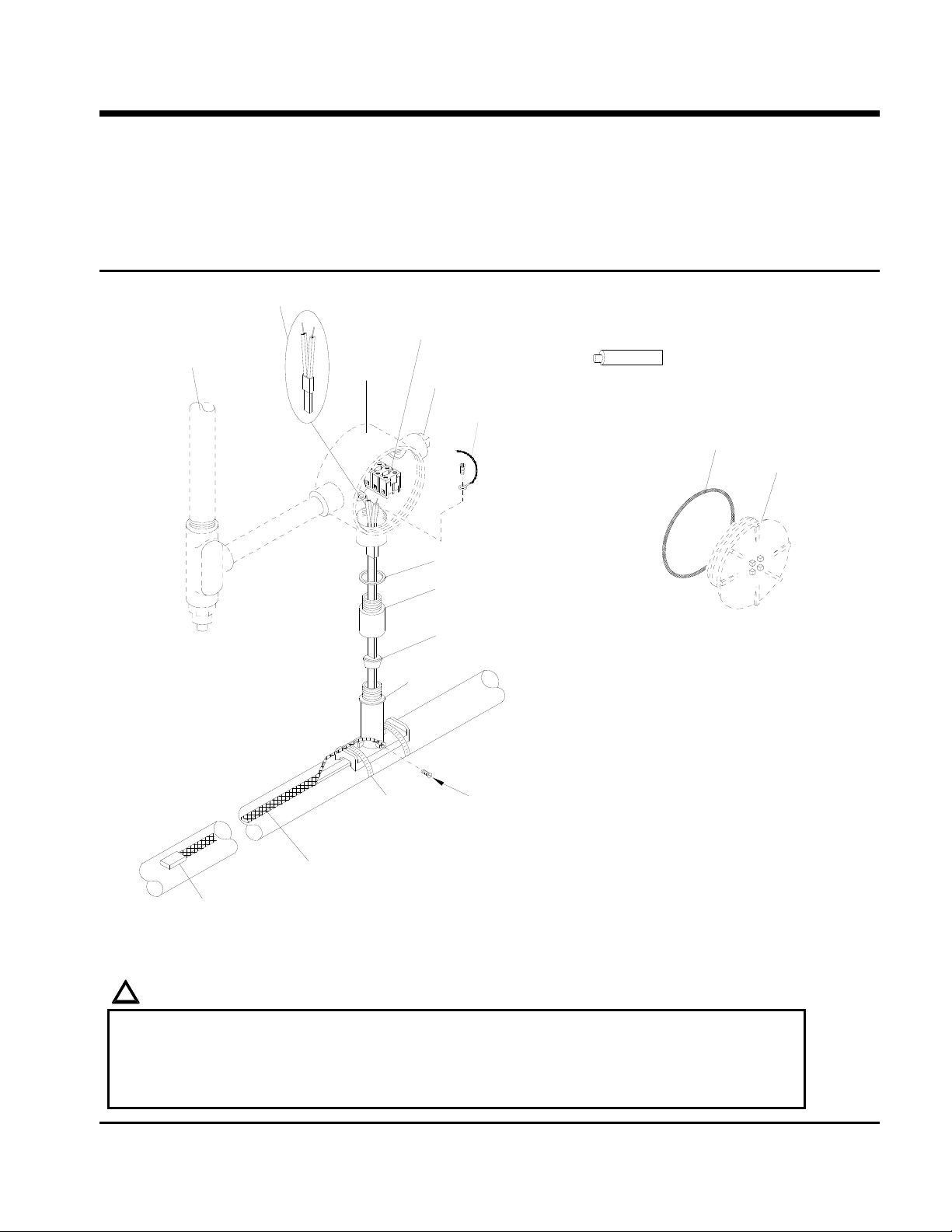
ALT-BC STANDARD POWER CONNECTION KIT
DESCRIPTION
The ALT-BC Standard Power Connection Kit is
constructed of cast aluminum for use with all versions
of Nelson Heat Tracing Systems’ LT, CLT, HLT and
NC heater cables. Compatible for use with any vendor’s
heater cables smaller than 11mm (0.44”) diameter.
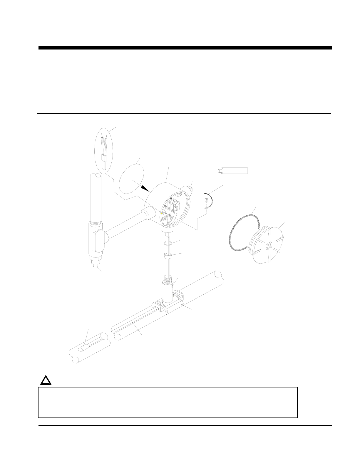
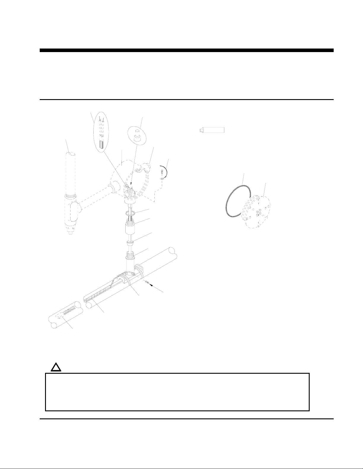
Power Termination
Junction Box
Conduit Plug
*Ground Wire
(for grounding of braid)
KIT CONTENTS
1 Junction Box 1 Power Termination
1 Label 1 Washer
1 Terminal Block 1 Ground Screw
1 Conduit Plug 1 End Seal
1 Sealing Grommet 1 Tube of Silicone
1 Stand-off 2 Pipe Clamps
Silicone
Box Cover Gasket
INSTRUCTIONS
Box Cover
Washer; metal
**Sealing Grommet
*Conduit & Drain
*Heater Cable; braided cable optional
(see warnings)
End Seal
Stand-off
Pipe Clamp
**Sealing Grommet
J-Grommet - Overjacket Products
B-Grommet - Base Products
U-Grommet - Double Entry or non-standard construction
(For dual connections 1 additional power termination
and end will be included in kit.)
*ITEMS NOT INCLUDED IN KIT
Note: This detail shows Braided “CB” Product only. For Overjacket “J” or “JT” Products, see
diagram on sheet 8.
!
WARNINGS:
• Article 427 of the National Electric Code requires that all heaters shall have metal coverings and
be provided with branch circuit ground-fault protection.
• If nuisance tripping of ground fault breakers occurs due to condensation in the junction box,
electrical connections should be moisture proofed by use of a coating or sealant.
P.O. BOX 726 TULSA, OK 74101 TEL 918-627-5530 FAX 918-641-7336 www.nelsonheaters.com
September 2005
GA-1865 Rev. 6
Sheet 1 of 8
Page 2
NELSON™ HEAT TRACING SYSTEMS INSTALLATION
ALT-BC STANDARD POWER CONNECTION KIT
INSTRUCTIONS
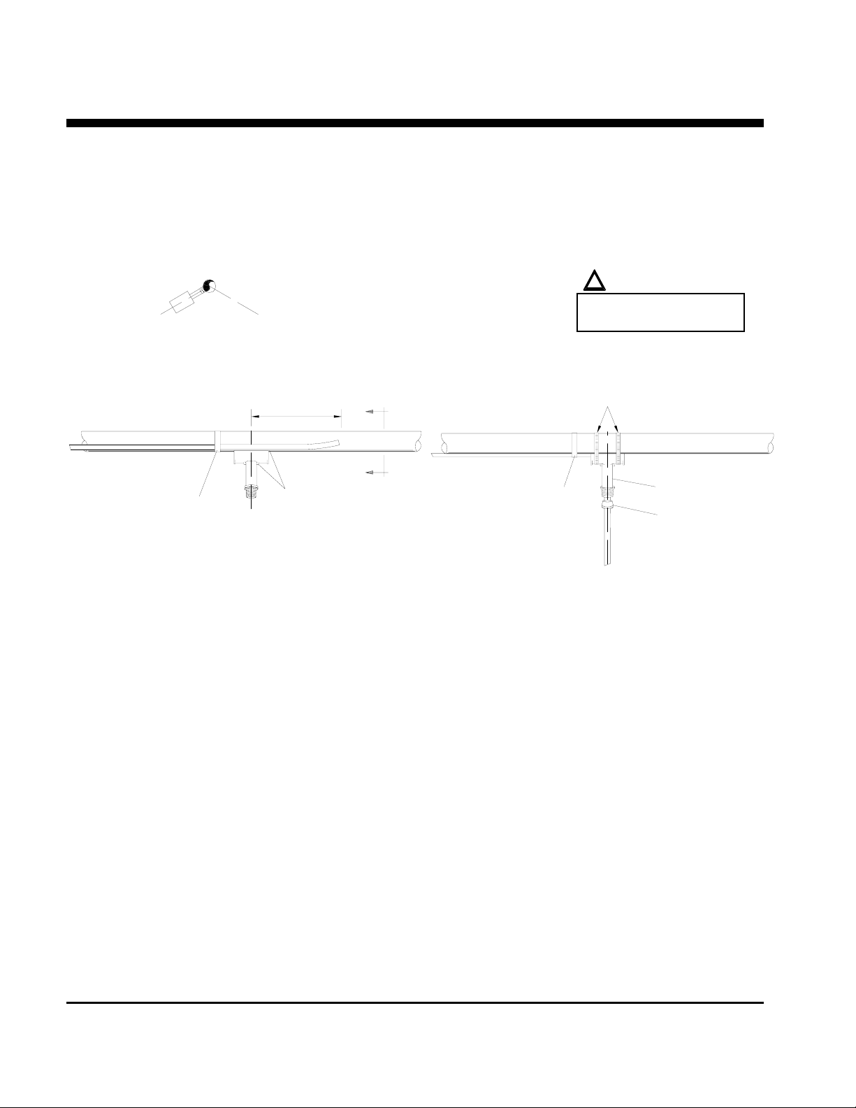
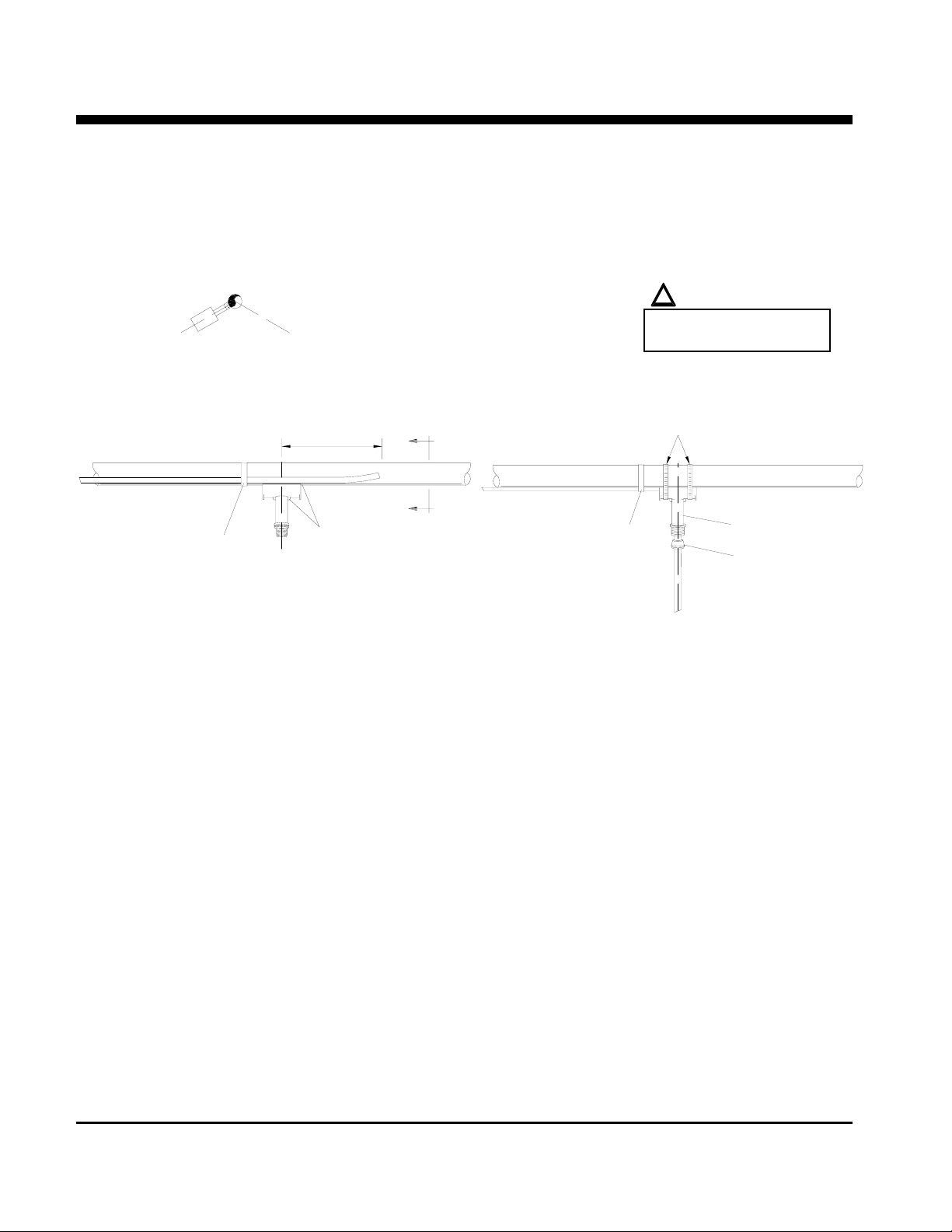
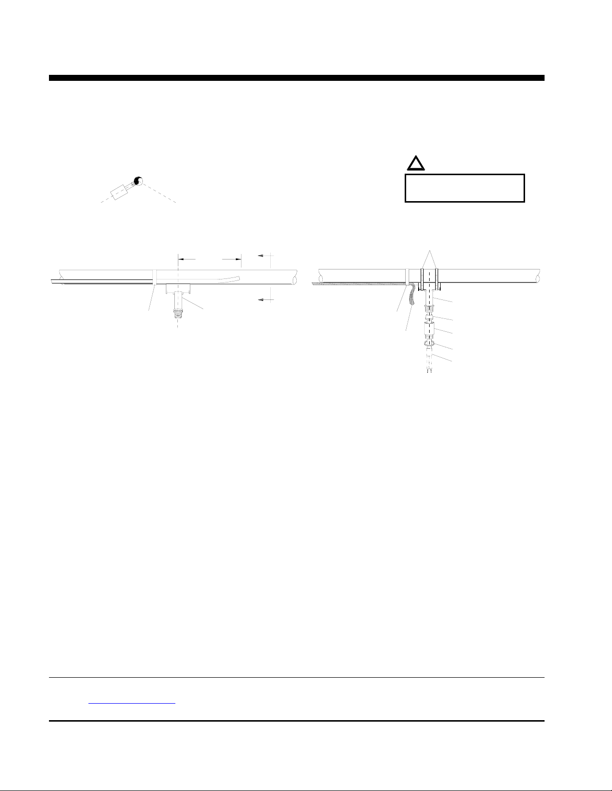
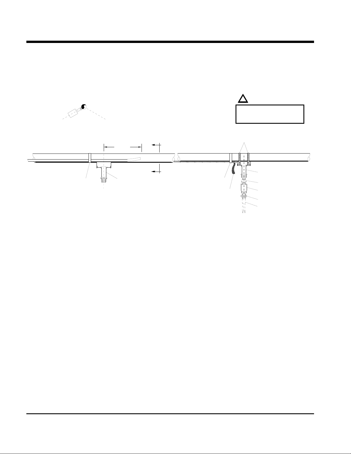
STAND-OFF POSITIONING
Section View A A
(recommend installing at the
4 or 8 o'clock positions.)
!
WARNING:
Do not place pipe clamps
8 o'clock
4 o'clock
254mm (10")
A
over the heater cable.
Pipe Clamps
A
Fiberglass Tape
not included in kit
Stand-off
Fiberglass Tape
not included in kit
Stand-off
Sealing Grommet
Mark pipe where stand-off will be mounted. See drawing above.
Push heater cable through bottom opening of stand-off.
Place stand-off on pipe and fasten with pipe clamps included.
Slide the sealing grommet over the heater cable and position inside stand-off opening:
For Braided “CB” Products only:
See “Sealing Grommet Installation for Braided “CB” Products” on sheet 3.
Apply silicone around the heater cable on top of the sealing grommet and fill any voids in sealing grommet.
Prepare heater cable for power termination:
for Braided “CB” Products, see sheet 3.
for Overjacket “J” or “JT” Products, see sheet 4.
Terminate heater cable, see sheet 7.
P.O. BOX 726 TULSA, OK 74101 TEL 918-627-5530 FAX 918-641-7336 www.nelsonheaters.com
GA-1865 Rev. 6
Sheet 2 of 8
September 2005
Page 3
NELSON™ HEAT TRACING SYSTEMS INSTALLATION
ALT-BC STANDARD POWER CONNECTION KIT
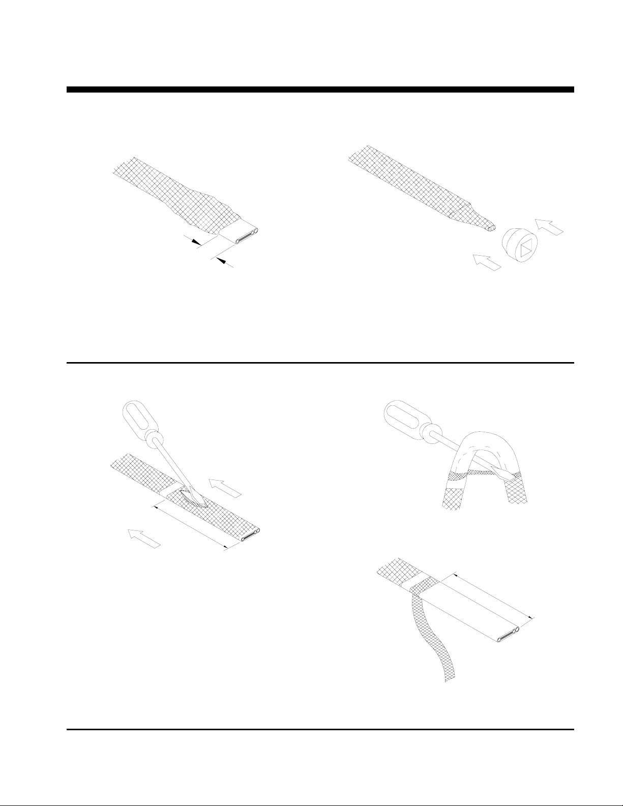
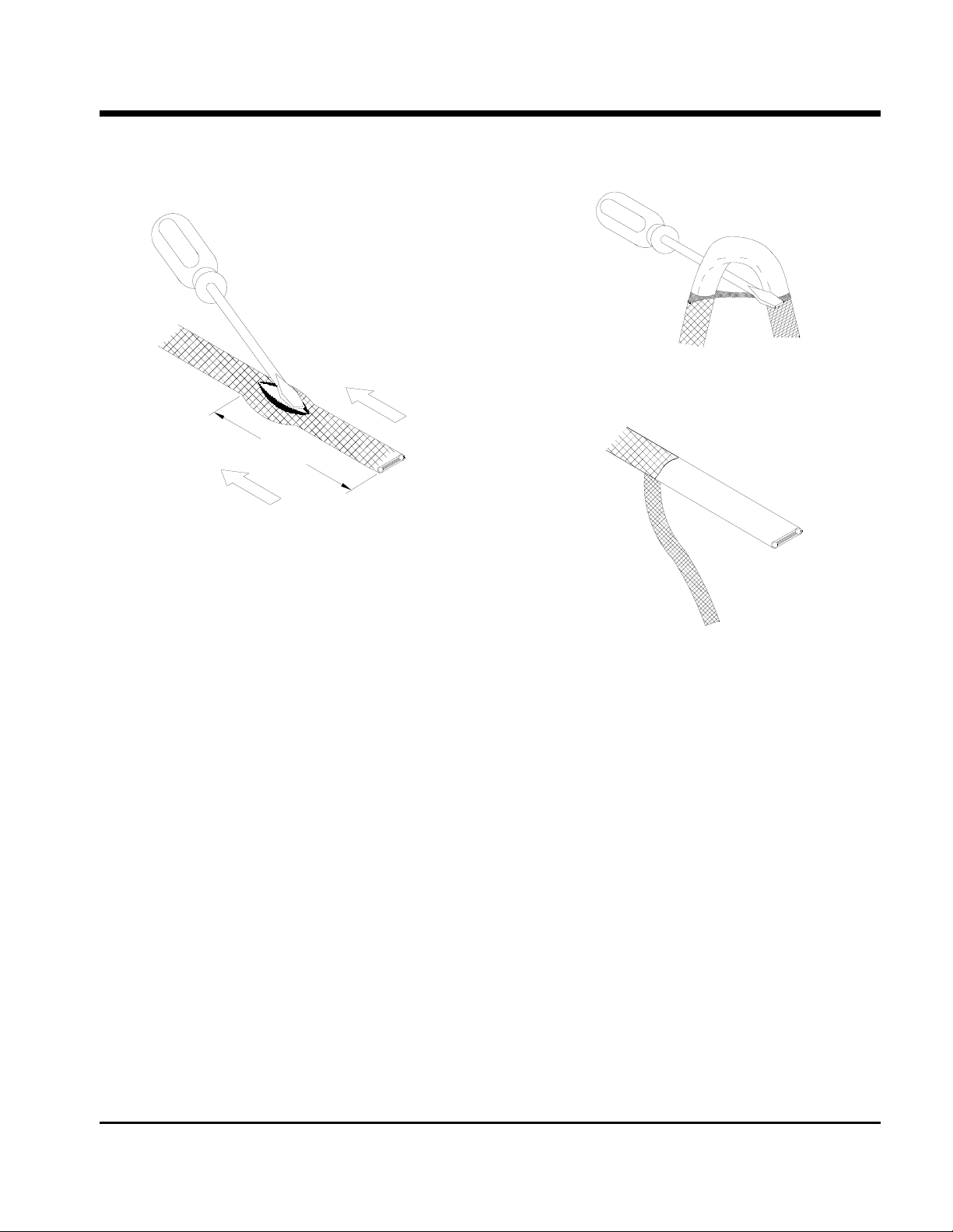
SEALING GROMMET INSTALLATION FOR BRAIDED “CB” PRODUCTS
13mm (.5")
Slide braid back, allowing at least 13mm (.5”) of
heater cable exposed.
Cut and remove the exposed heater cable.
BRAIDED “CB” PRODUCTS
Slide braid back over heater cable and twist excess
braid into a pigtail.
Slide the sealing grommet over the heater cable and
position inside stand-off opening.
Continue with step 5 on sheet 2.
INSTRUCTIONS
127mm (.5")
Bend heater cable and work it through the braid
opening.
Secure heater cable braid with fiberglass tape,
allowing 127mm (5”) of cable for stripping.
114mm (4.5")
Slide braid back towards the fiberglass tape creating
a bulge.
At the bulge, separate the braid to make an opening.
Pull the braid tigh t.
Proceed to “LT, CLT & HLT Products” on sheet 5.
P.O. BOX 726 TULSA, OK 74101 TEL 918-627-5530 FAX 918-641-7336 www.nelsonheaters.com
September 2005
GA-1865 Rev. 6
Sheet 3 of 8
Page 4
NELSON™ HEAT TRACING SYSTEMS INSTALLATION
ALT-BC STANDARD POWER CONNECTION KIT
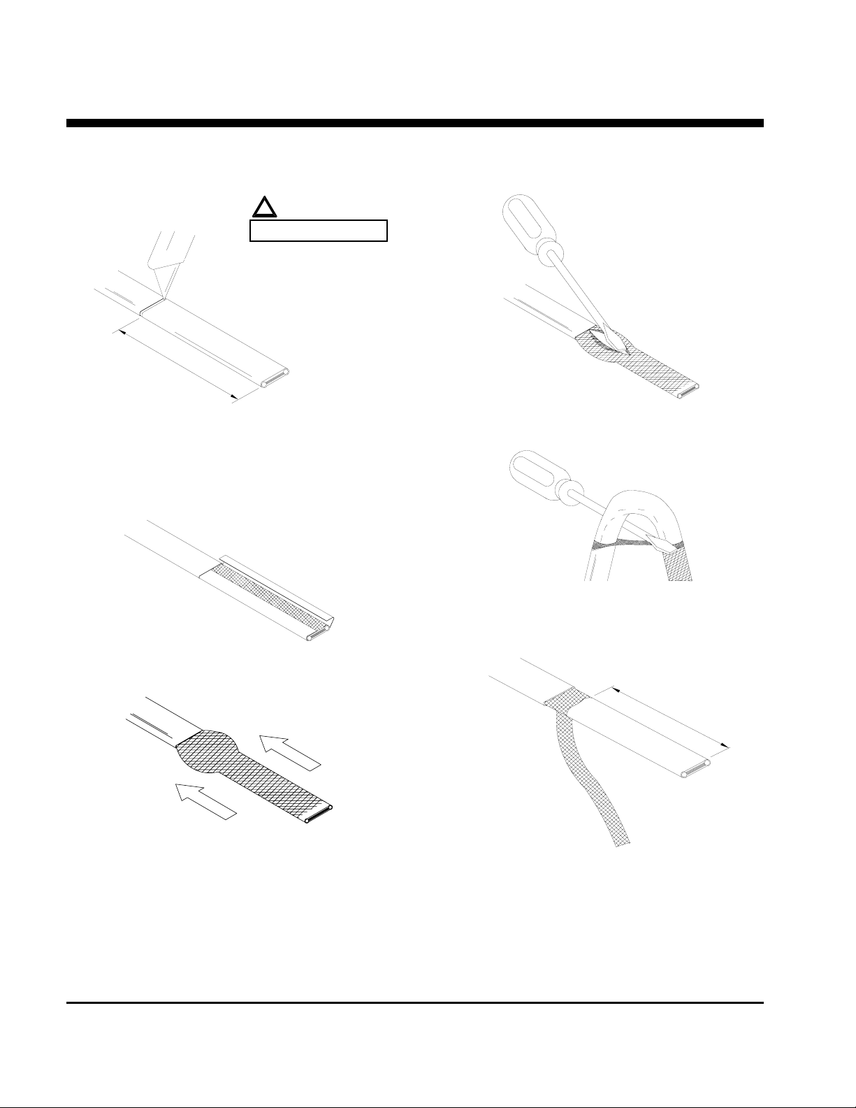
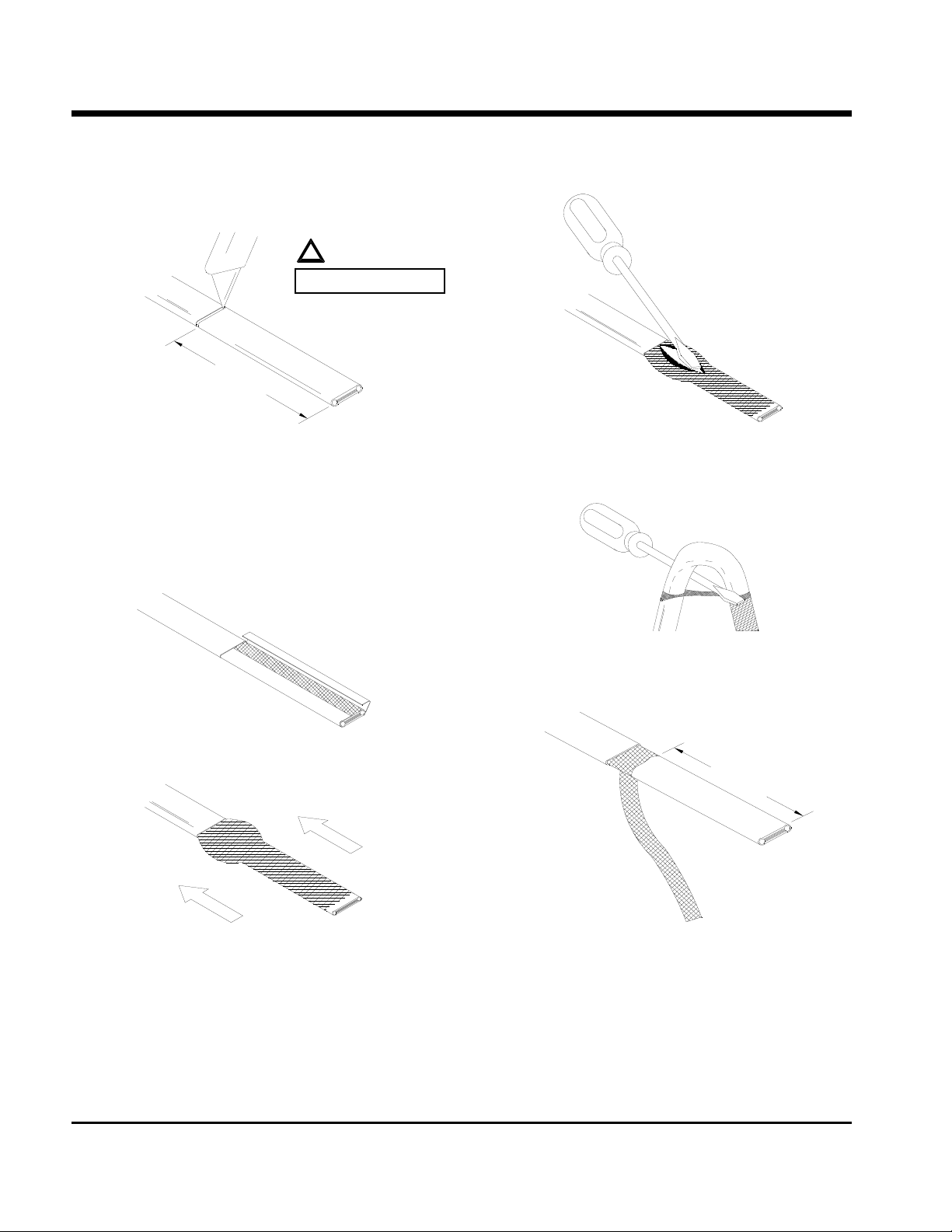
OVERJACKET PRODUCTS
127mm (5")
!
WARNING:
DO NOT CUT BRAID
Lightly cut around heater overjacket 127mm (5")
from the end. Bend cable to break overjacket.
Lightly cut overjacket up the center between first
cut mark and the cable end. Bend cable to break
overjacket.
At the bulge, separate the braid to make an opening.
INSTRUCTIONS
Remove overjacket from heater cable.
Move braid back toward the overjacket, creating
a bulge.
While bending the heater cable, work it through the
braid opening.
114mm (4.5")
Pull the braid tight.
Proceed to “LT, CLT & HLT Products” on sheet 5.
P.O. BOX 726 TULSA, OK 74101 TEL 918-627-5530 FAX 918-641-7336 www.nelsonheaters.com
GA-1865 Rev. 6
Sheet 4 of 8
September 2005
Page 5
NELSON™ HEAT TRACING SYSTEMS INSTALLATION
ALT-BC STANDARD POWER CONNECTION KIT
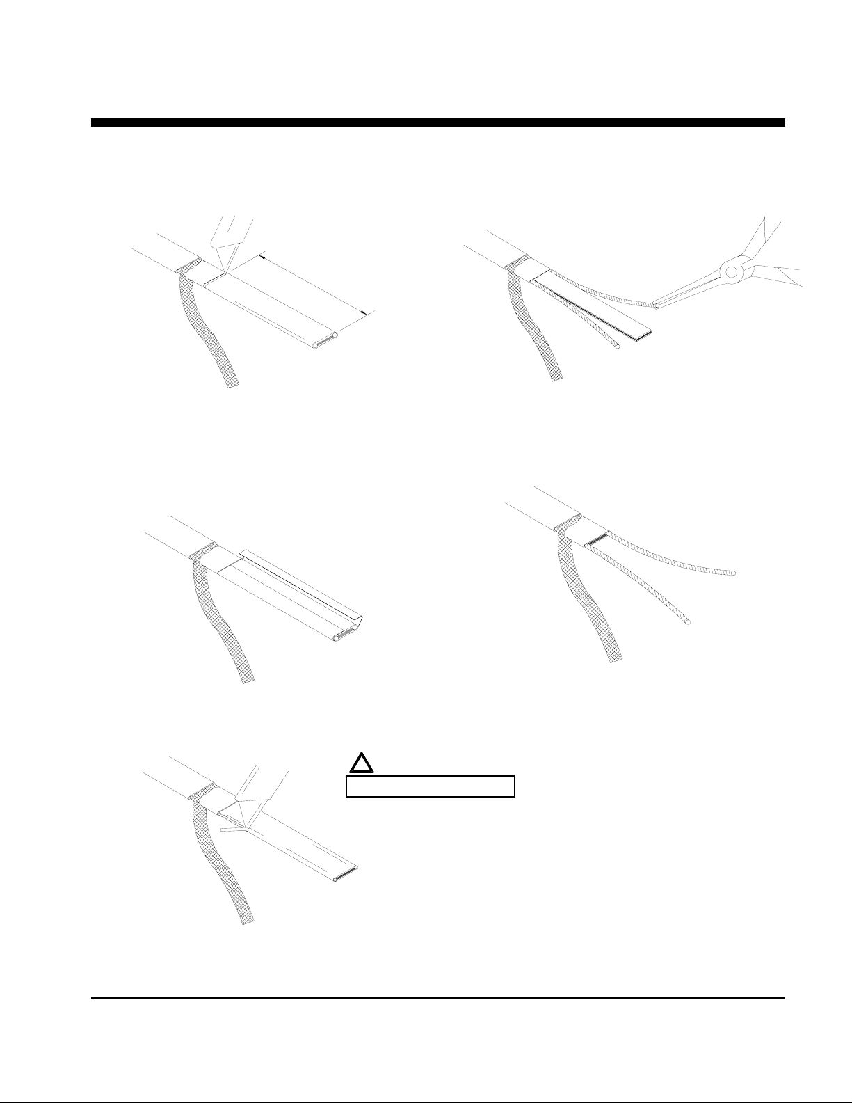
FOR ALL NELSON LT, CLT & HLT PRODUCTS
(See sheet 6 for an alternate stripping method for HLT products.)
102mm (4")
Lightly cut around cable outer jacket 102mm (4")
from the end. Bend cable to break outer jacket.
Lightly cut the outer jacket up the center between
the first cut mark & the cable end. Bend cable to
break outer jacket.
Starting at the end, pull each bus wire away from
the core material.
Remove exposed core material.
INSTRUCTIONS
Remove the jacket from the heater cable.
!
DO NOT CUT BUS WIRES
Cut 6mm (0.25") off the end of each bus wire.
Proceed to “Power Termination” on sheet 7.
Shave the core material from the outside of
each bus wire.
P.O. BOX 726 TULSA, OK 74101 TEL 918-627-5530 FAX 918-641-7336 www.nelsonheaters.com
GA-1865 Rev. 6
Sheet 5 of 8
September 2005
Page 6
NELSON™ HEAT TRACING SYSTEMS INSTALLATION
ALT-BC STANDARD POWER CONNECTION KIT
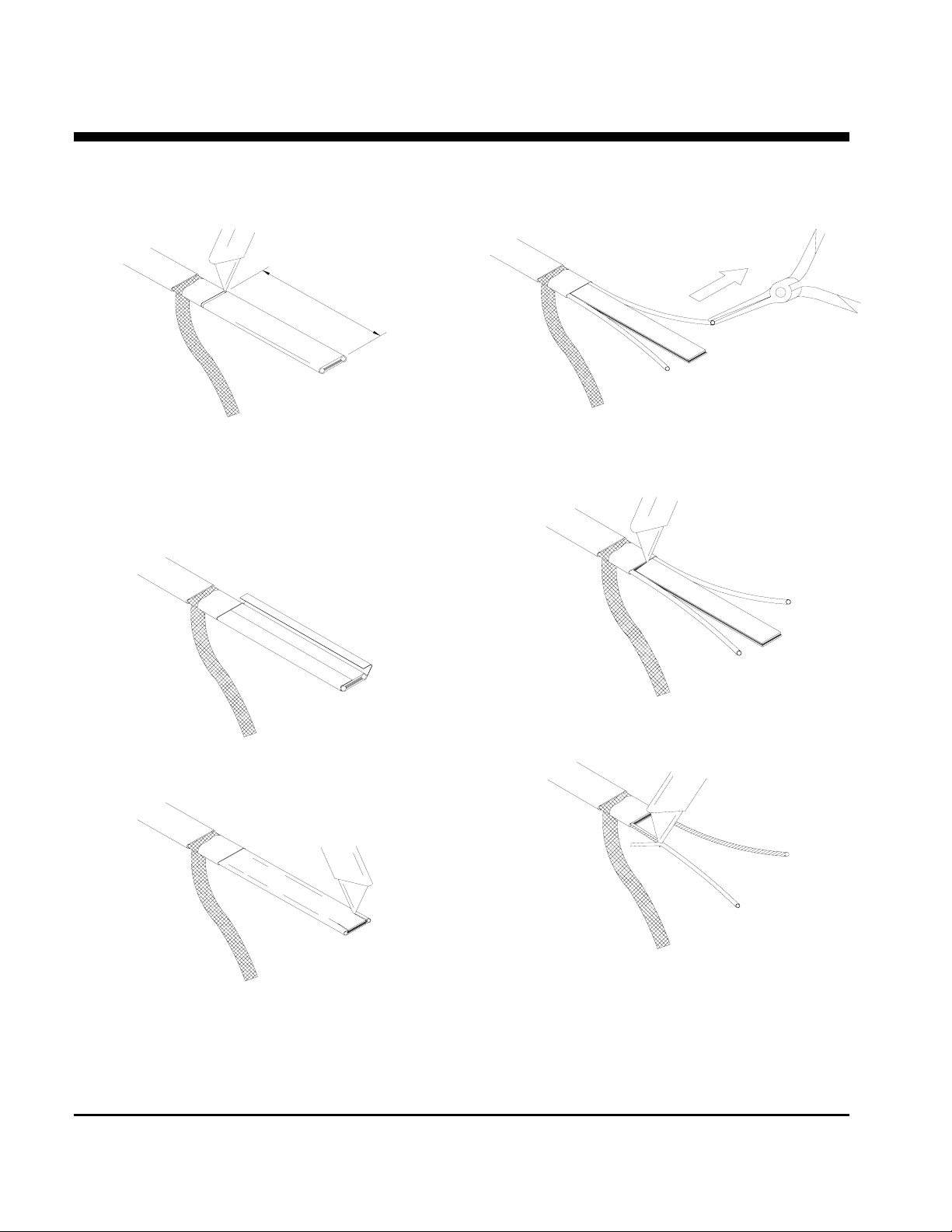
HLT PRODUCTS ALTERNATE STRIPPING METHOD
102mm (4")
Lightly cut around cable outer jacket 102mm (4")
from the end. Bend cable to break outer jacket.
Lightly cut the outer jacket up the center between
the first cut mark & the cable end. Bend cable to
break outer jacket.
Starting at the end, in the same plane as the cable,
pull each bus wire away from the core material.
INSTRUCTIONS
Remove the exposed core material.
Remove the jacket from the heater cable.
Remove the remaining core material off the outside
Make a cut inside each bus wire.
of each bus wire.
Cut 6mm (0.25") off the end of each bus wire.
Proceed to “Power Termination” on sheet 7.
P.O. BOX 726 TULSA, OK 74101 TEL 918-627-5530 FAX 918-641-7336 www.nelsonheaters.com
GA-1865 Rev. 6
Sheet 6 of 8
September 2005
Page 7
NELSON™ HEAT TRACING SYSTEMS INSTALLATION
ALT-BC STANDARD POWER CONNECTION KIT
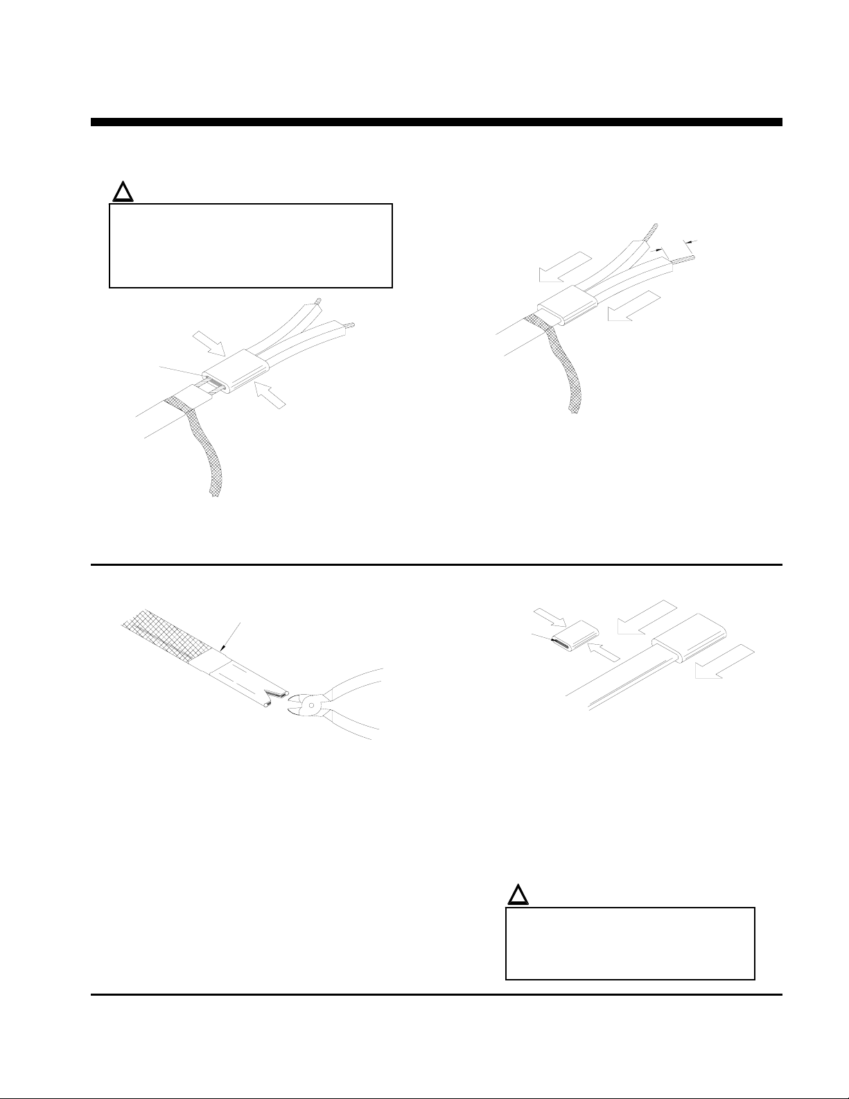
POWER TERMINATION
!
WARNING:
• Bus wires must not touch or cross while
inserting into power termination.
• Only power terminations / end seals
specifically approved for the vendors style
and type of heater cable must be used.
apply silicone here
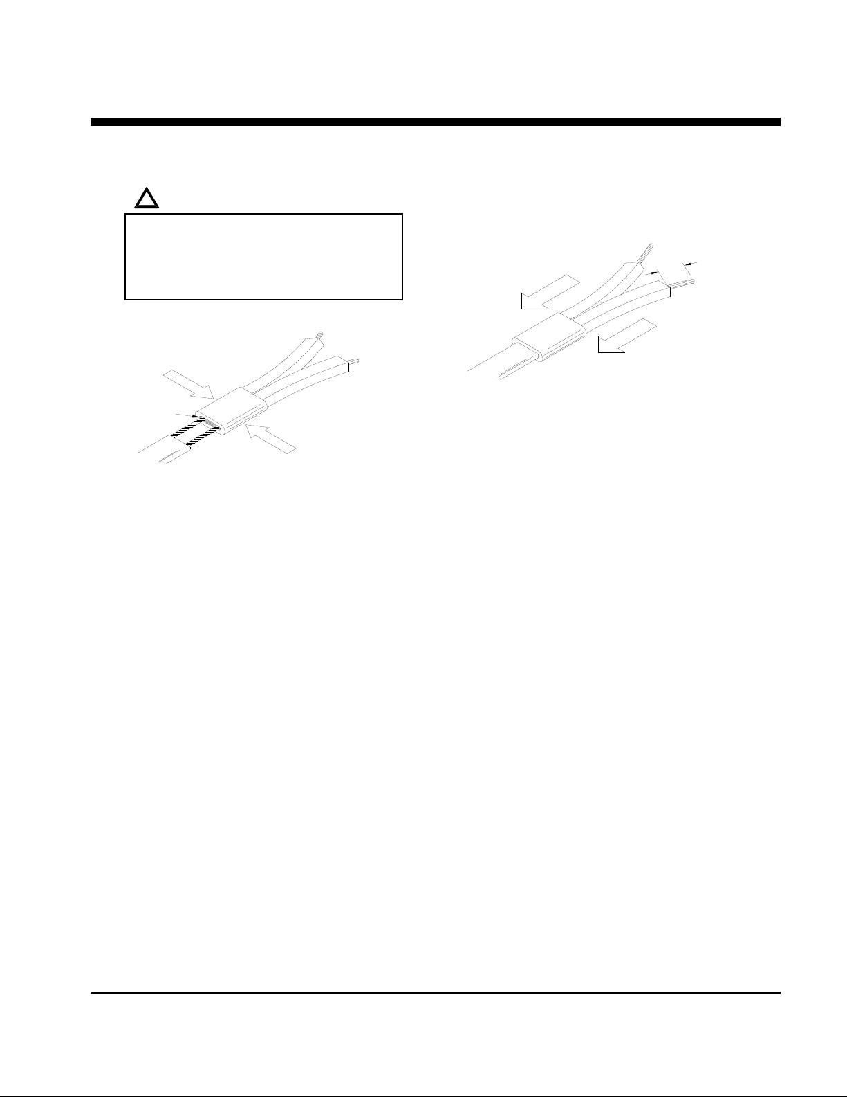
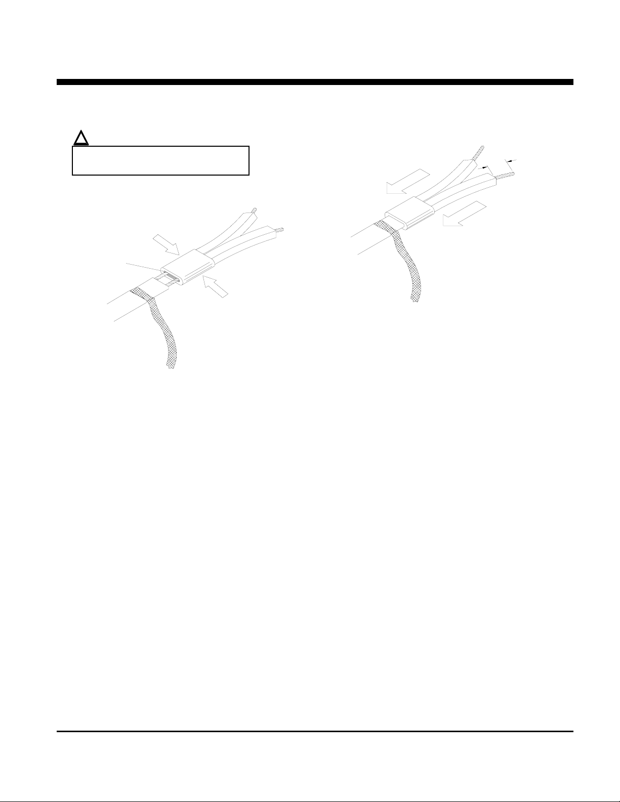
Insert bus wires into power termination.
Squeeze power termination opening and fill with
silicone.
END SEAL
Fiberglass Tape
not included in kit
Push power termination to overlap jacket.
The silicone will set up in about 30 minutes with a
complete cure after 24 hours.
Proceed to “Power Termination” on sheet 8.
apply silicone here
INSTRUCTIONS
13mm (.5")
Braided “CB” Products only:
Cut braid back 25mm (1") & tape in place with
fiberglass tape.
Overjacket “J” or “JT” Products only:
Remove 13mm (0.5") of overjacket exposing the
braid, then remove the 13mm (0.5”) of exposed
braid.
Make a 10mm (0.4") cut at the end of the heater
cable.
P.O. BOX 726 TULSA, OK 74101 TEL 918-627-5530 FAX 918-641-7336 www.nelsonheaters.com
Squeeze end seal and fill with silicone.
Push end seal over the heater cable.
Overjacket “J” or “JT” Products only:
The end seal should overlap the overjacket.
The silicone will set up in about 30 minutes with a
complete cure after 24 hours.
Proceed to “Power Connection” on sheet 8
!
WARNING:
• Do not megger or hi-pot until
silicone is completely secured.
• Braid must be kept away from
bus wires or shorting will occur.
GA-1865 Rev. 6
September 2005
Sheet 7 of 8
Page 8
NELSON™ HEAT TRACING SYSTEMS INSTALLATION
ALT-BC STANDARD POWER CONNECTION KIT
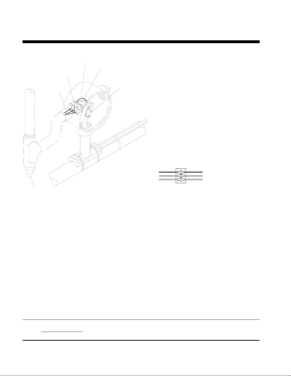
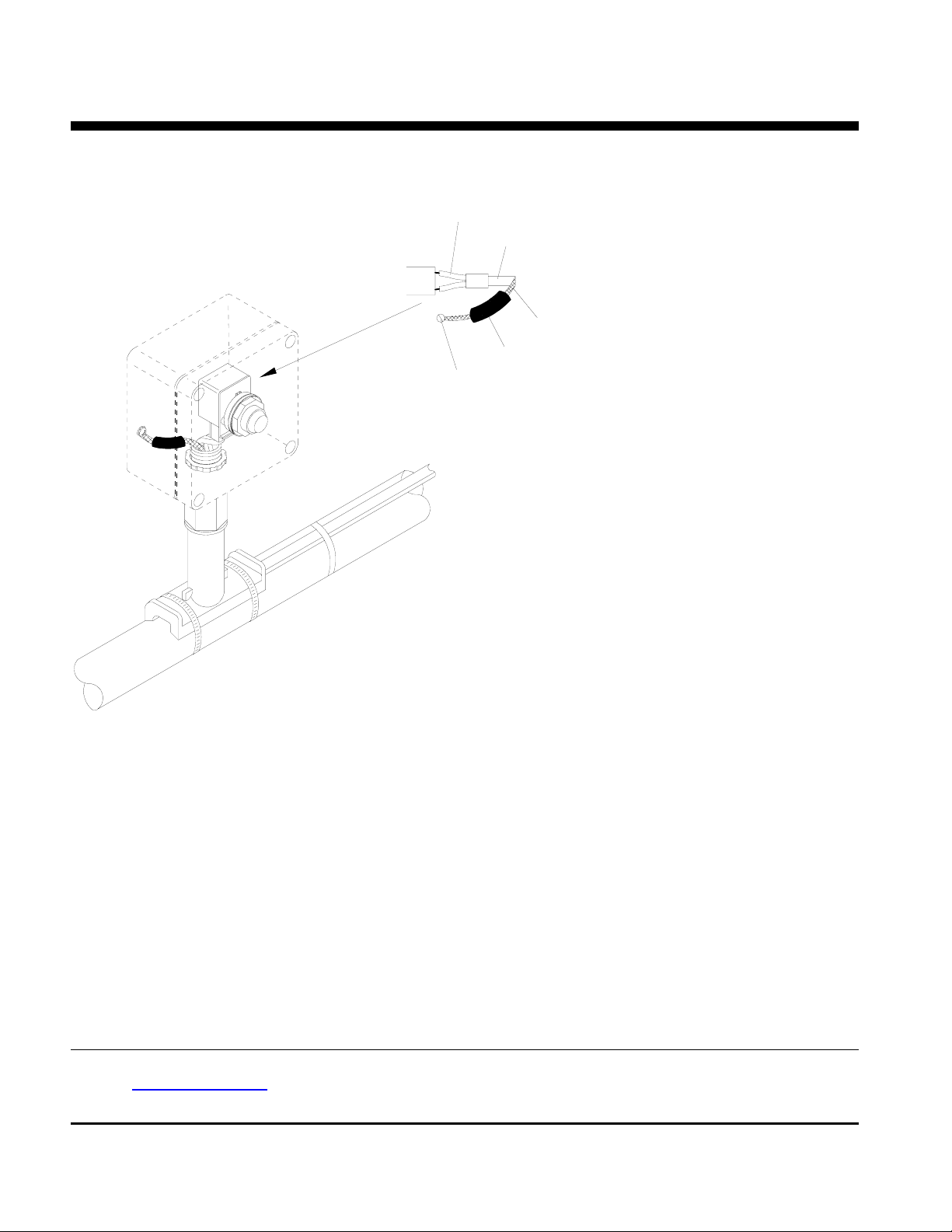
POWER CONNECTION
Terminal Block
Ground Wire
*Ground Wire
Braid
Power Termination
TERMINAL BLOCK CONNECTION
Ground Wire
Power Leads
INSTRUCTIONS
Braid
Heater Cable
*Conduit & Drain; not included in kit
(must be positioned lower than the junction box)
Note: This detail shows Overjacket “J” or “JT” Products. For Braided “CB” Products, see diagram on
sheet 1.
Slide washer over heater cable and position at the sealing grommet.
Secure junction box onto stand-off until tightly fitted. DO NOT OVER TIGHTEN.
Connect the power wiring and heater cable to terminal block.
Connect ground wire to terminal block inside junction box using the ground screw. See diagram on sheet 1.
Connect ground wire and braid to terminal block. See diagram above.
For Overjacket J or JT Products only:
Apply silicone at point braid leaves the overjacket.
Push all wires, cable and terminal block inside junction box.
Install box cover gasket and box cover onto junction box.
Apply label to the smooth side of junction; fill-in the Voltage, Catalog No. & Wattage blocks on the label with the
actual field installed data.
Nelson Heat Tracing Systems products are supplied with a limited warranty. Complete Terms and Conditions may be found on Nelson's
website at
P.O. BOX 726 TULSA, OK 74101 TEL 918-627-5530 FAX 918-641-7336 www.nelsonheaters.com
GA-1865 Rev. 6
Sheet 8 of 8
September 2005
www.nelsonheaters.com.
Page 9
NELSON™ HEAT TRACING SYSTEMS INSTALLATION
ALT-BCL STANDARD POWER CONNECTION KIT
DESCRIPTION
The ALT-BCL Standard Power Connection Kit is
constructed of cast aluminum for use with Nelson Heat Tracing
Systems’LLT heater cables.
Power T erm ina tion
Label
Junction Box
Conduit Plug
KIT CONTENTS
1 Junction Box 1 Power Termination
1 Label 1 Washer
1 Terminal Block 1 Ground Screw
1 Conduit Plug 1 End Seal
1 Sealing Grommet 2 Tubes of Silicone
1 Stand-off 2 Pipe Clamps
Silicone
*Ground Wire
(for grounding of braid)
INSTRUCTIONS
Box Cover Gasket
Washer, metal
Sealing Grommet
*Conduit & Dr ain
End Seal
*Heater Cab le
Standoff
Pipe Clamps
*TH E SE IT E M S N O T IN C L U D E D IN K IT .
!
WARNINGS:
• Article 427 of the National Electric Code requires that all heaters shall have metal coverings and
be provided with branch circuit ground-fault protection.
• If nuisance tripping of ground fault breakers occurs due to condensation in the junction box,
electrical connections should be moisture proofed by use of a coating or sealant.
Box Cover
P.O. BOX 726 TULSA, OK 74101 TEL 918-627-5530 FAX 918-641-7336 www.nelsonheaters.com
GA-2179 Rev. 1
Sheet 1 of 6
September 2005
Page 10
NELSON™ HEAT TRACING SYSTEMS
INSTALLATION
ALT-BCL STANDARD POWER CONNECTION KIT INSTRUCTIONS
STAND-OFF POSITIONING
Section View A A
(recommend installing at the
4 or 8 o'clock positions.)
!
WARNING:
Do not place pipe clamps
8 o'clock
4 o'clock
254mm (10")
A
over the heater cable.
Pipe Clamps
A
Fiberglass Tape
not included in kit
Stand-off
Fiberglass Tape
not included in kit
Stand-off
Sealing Grommet
Mark pipe where stand-off will be mounted. See drawing above.
Push heater cable through bottom opening of stand-off.
Place stand-off on pipe and fasten with pipe clamps included.
Slide the sealing grommet over the heater cable and position inside stand-off opening:
Apply silicone around the heater cable on top of the sealing grommet and fill any voids in sealing grommet.
Prepare heater cable for power termination:
See sheet 3.
Terminate heater cable, see sheet 5.
.
P.O. BOX 726 TULSA, OK 74101 TEL 918-627-5530 FAX 918-641-7336 www.nelsonheaters.com
GA-2179 Rev. 1
Sheet 2 of 6
September 2005
Page 11
NELSON™ HEAT TRACING SYSTEMS
INSTALLATION
ALT-BCL STANDARD POWER CONNECTION KIT INSTRUCTIONS
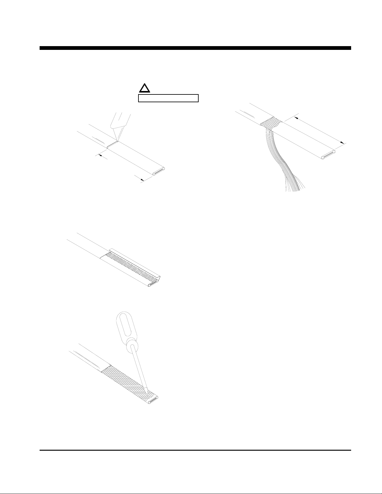
OVERJACKET STRIPPING PROCEDURES
1
0
8
m
m
(
4
.
!
WARNING:
DO NOT CUT BRAID
2
5
"
)
Lightly cut around heater overjacket 127mm (5")
from the end. Bend cable to break the overjacket.
Lightly cut overjacket up the center between first
cut mark and the cable end. Bend cable to break
outer jacket will be removed in a subsuquent
operation do not puncture it with the awl.
102mm(4" )
After the braid has been unraveled so that it looks
similar to the illustration above pull it tight and twist
the loose wires together.
Proceed to “Outer Jacket Stripping Procedures”,
sheet 4.
Remove overjacket from heater cable.
Using an awl or other sharp pointed device, unravel
the braid from the cable. Even though most of the
P.O. BOX 726 TULSA, OK 74101 TEL 918-627-5530 FAX 918-641-7336 www.nelsonheaters.com
GA-2179 Rev. 1
Sheet 3 of 6
September 2005
Page 12
NELSON™ HEAT TRACING SYSTEMS
INSTALLATION
ALT-BCL STANDARD POWER CONNECTION KIT INSTRUCTIONS
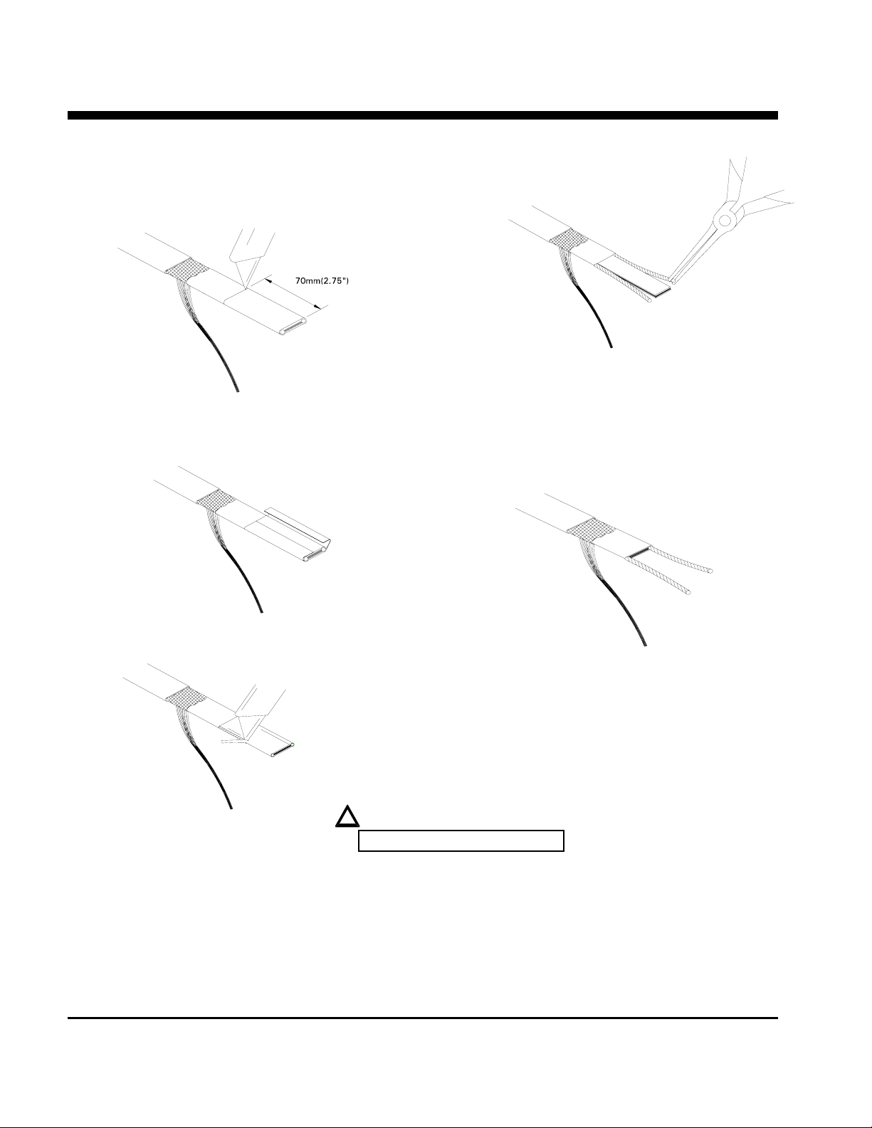
OUTER JACKET STRIPPING PROCEDURES
Lightly cut around heater outer jacket 102mm (4")
from the end. Bend cable to break outer jacket.
Lightly cut the outer jacket up the center between
the first cut mark & the cable end. Bend cable to
break outer jacket.
Starting at the end, pull each bus wire away
from the core material. Do not disturb the “lay” of
the wire stranding. Failure to comply will prevent
installation of the power termination boot.
Remove exposed core material.
Remove jacket from the heater cable.
Proceed to “Power Termination Procedures”,
sheet 5.
!
DO NOT CUT BUS WIRES
Shave core material from the outside of
each bus wire.
P.O. BOX 726 TULSA, OK 74101 TEL 918-627-5530 FAX 918-641-7336 www.nelsonheaters.com
GA-2179 Rev. 1
Sheet 4 of 6
September 2005
Page 13
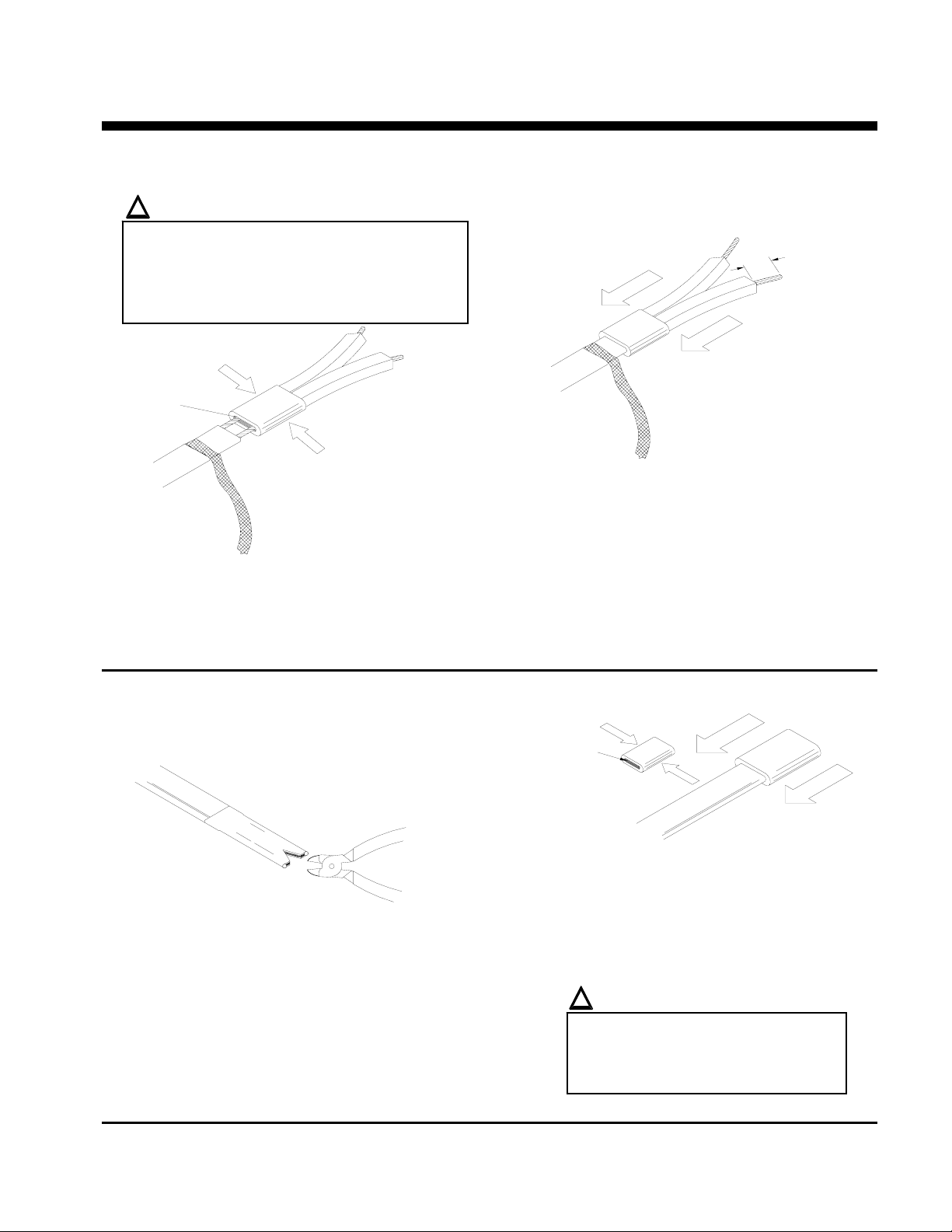
NELSON™ HEAT TRACING SYSTEMS INSTALLATION
ALT-BCL STANDARD POWER CONNECTION KIT
POWER TERMINATION
!
WARNING:
• Bus wires must not touch or cross while
inserting into power termination.
• Only power terminations / end seals
specifically approved for the vendor’s style and
type of heater cable must be used.
apply silicone here
Before installing the boot, slightly cock the end of
each wire away from the other and apply a small
amount of silicone to the open end of the boot.
Insert bus wires into power termination (boot).
END SEAL
Squeeze power termination opening and fill with
silicone.
Push power termination to overlap jacket.
The silicone will set up in about 30 minutes with a
complete cure after 24 hours.
Proceed to “Power Connection” on sheet 8.
INSTRUCTIONS
13mm (.5")
apply silicone here
Squeeze end seal and fill with silicone.
Push end seal over the heater cable.
Remove 13mm (0.5") of overjacket exposing the
braid, then remove the 13mm (0.5”) of exposed
braid.
Make a 5mm (0.2") cut at the end of the heater
cable, as shown above.
P.O. BOX 726 TULSA, OK 74101 TEL 918-627-5530 FAX 918-641-7336 www.nelsonheaters.com
The end seal should overlap the overjacket.
The silicone will set up in about 30 minutes with a
complete cure after 24 hours.
Proceed to “Power Connection” on sheet 8
!
WARNING:
• Do not megger or hi-pot until
silicone is completely secured.
• Braid must be kept away from
bus wires or shorting will occur.
GA-2179 Rev. 1
September 2005
Sheet 5 of 6
Page 14
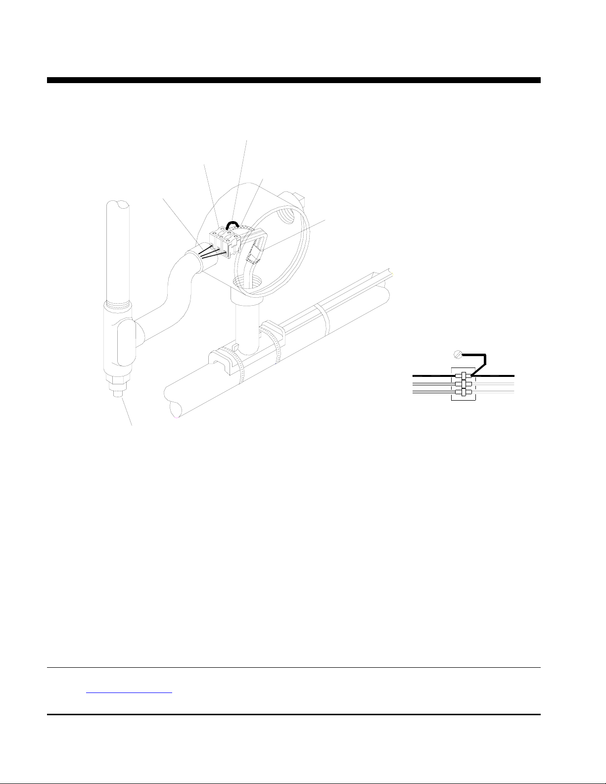
NELSON™ HEAT TRACING SYSTEMS INSTALLATION
ALT-BCL STANDARD POWER CONNECTION KIT
POWER CONNECTION
* Ground W ire
Terminal Block
Braid
Ground W ire
Pow e r T erm ina t ion
TERM INA L BLOCK CONNECTION
Ground Screw in enclosure
Ground W ire
Pow er Lea ds
INSTRUCTIONS
* Ground W ire
Braid
Heater Cable
* Conduit and Dra in; not included
(should be positioned lower than t he junct ion box)
Slide washer over heater cable and position at the sealing grommet.
Secure junction box onto stand-off until tightly fitted. DO NOT OVER TIGHTEN.
Connect the power wiring and heater cable to terminal block.
Connect ground wire to terminal block inside junction box using the ground screw. See diagram on sheet 1.
Connect ground wire and braid to terminal block. See diagram above.
Apply silicone at point braid leaves the overjacket.
Push all wires, cable and terminal block inside junction box.
Install box cover gasket and box cover onto junction box.
Apply label to the smooth side of junction; fill-in the Voltage, Catalog No. & Wattage blocks on the label with the
actual field installed data.
Nelson Heat Tracing Systems products are supplied with a limited warranty. Complete Terms and Conditions may be found on Nelson's
website at
www.nelsonheaters.com.
P.O. BOX 726 TULSA, OK 74101 TEL 918-627-5530 FAX 918-641-7336 www.nelsonheaters.com
GA-2179 Rev. 1
Sheet 6 of 6
September 2005
Page 15
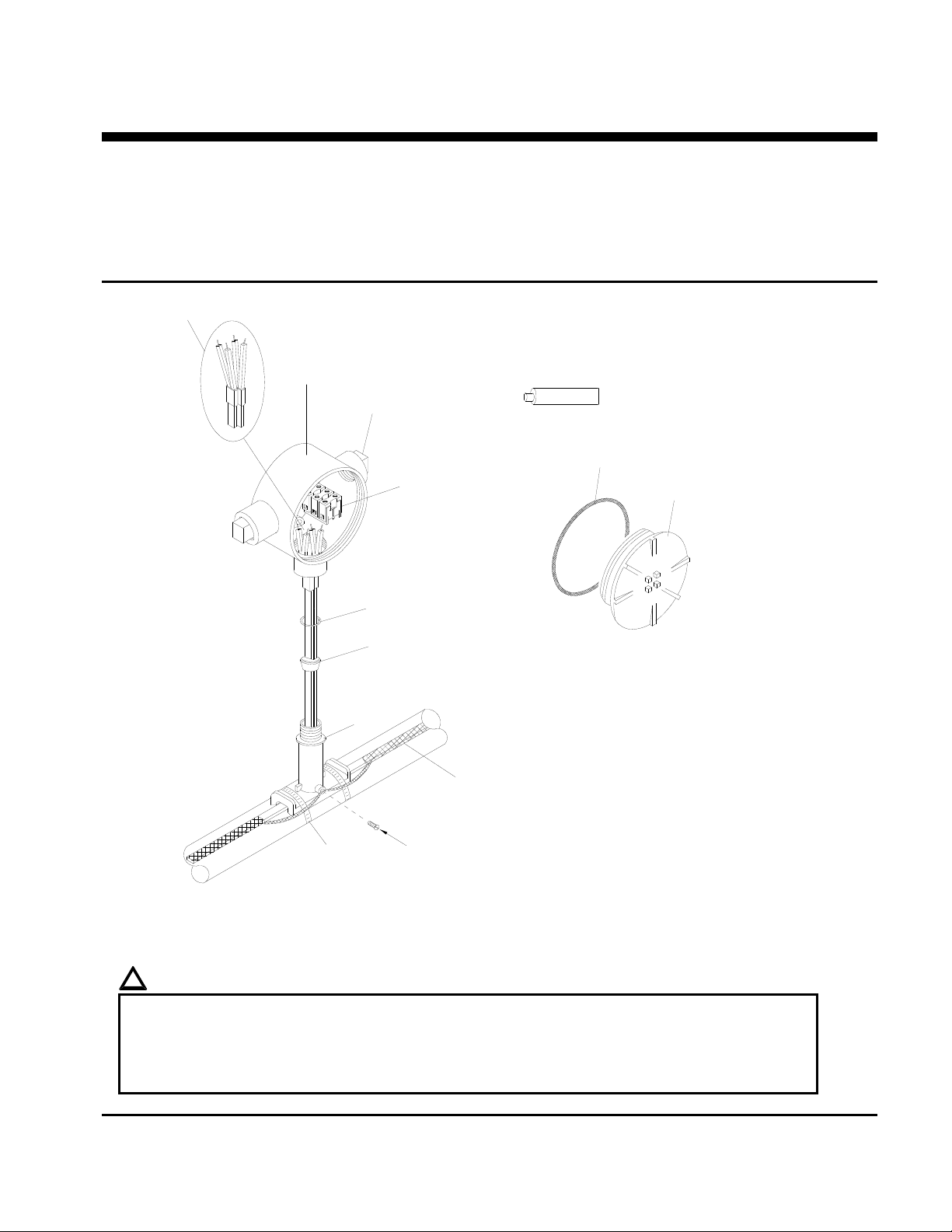
NELSON™ HEAT TRACING SYSTEMS
ALT-BS SPLICE CONNECTION KIT
INSTALLATION
INSTRUCTIONS
DESCRIPTION
The ALT-BS Splice Connection Kit is constructed of cast
aluminum for use all versions of Nelson Heat Tracing
Systems’ LT, CLT, HLT and NC heater cables. Compatible
for use with any vendor’s heater cables smaller than 11mm
(0.44”) diameter. Minimum installation temperature –40°C
(-40°F).
Power Terminations
Junction Box
Conduit Plug
Terminal Block
KIT CONTENTS
1 Junction Box 2 Power Terminations
Terminal Block 1 Washer
1
Conduit Plugs 1 Ground Screw
2
Sealing Grommet 1 Tube of Silicone
1
Stand-off 2 Pipe Clamps
1
Silicone
Box Cover Gasket
Box Cover
Washer; metal
Sealing Grommet
U-Grommet - Double Entry or non-standard construciton
Stand-off
Braid
*ITEMS NOT INCLUDED IN KIT
Pipe Clamps
Ground Screw
(for use with braided cables only)
Note: This detail shows external grounding of braid. For internal grounding of braid
(overjacket products), see sheet 8.
!
WARNINGS:
Canadian Div. 2 Hazardous installations must use internal ground connection of braid. See sheet 8.
Article 427 of the National Electric Code requires that all heaters shall have metal coverings and be
provided with branch circuit ground-fault protection.
If nuisance tripping of ground fault breakers occurs due to condensation in junction box, electrical
connections should be moisture proofed by use of a coating or sealant.
P.O. BOX 726 TULSA, OK 74101 TEL 918-627-5530 FAX 918-641-7336 www.nelsonheaters.com
GA-1866 Rev. 7
Sheet 1 of 8
January 2010
Page 16
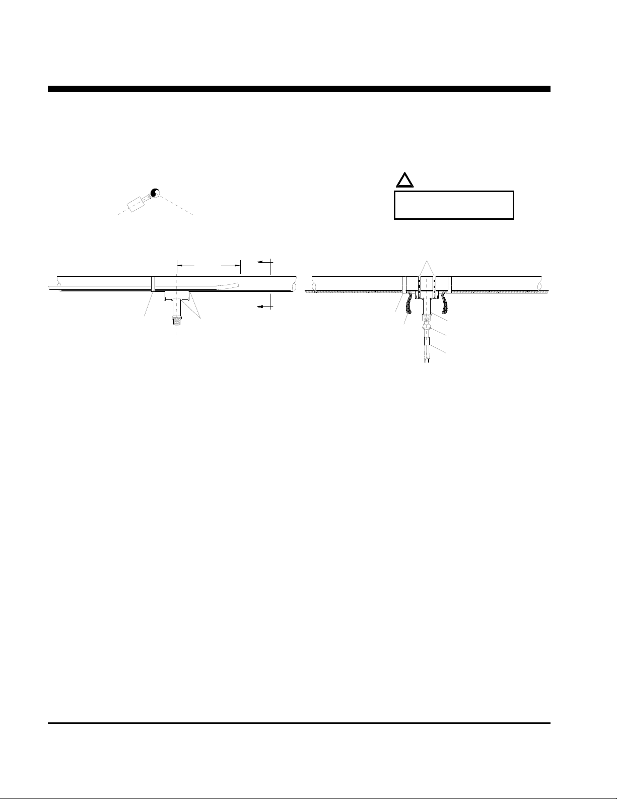
NELSON™ HEAT TRACING SYSTEMS
ALT-BS SPLICE CONNECTION KIT
STAND-OFF POSITIONING
Section View A A
(recommend installing at the
4 or 8 o'clock positions.)
8 o'clock
4 o'clock
254mm (10")
A
!
WARNING:
Do not place pipe clamps
over the heater cable.
Pipe Clamps
INSTALLATION
INSTRUCTIONS
*Fiberglass Tape
*ITEMS NOT INCLUDED IN KIT
A
Stand-off
*Fiberglass Tape
Braid
Stand-off
Sealing Grommet
Power Termination
Mark pipe where stand-off will be mounted.
For External Braid Connection - CB Products only:
Remove braid from heater cables, back to the point the cables leave the pipe. See Sheet 3.
Proceed to step 3 below.
For Internal Braid Connection - CB, J or JT Products:
Proceed to step 3 below.
Push heater cable through the bottom opening of stand-off.
Place stand-off on pipe and fasten with pipe clamps.
Slide the sealing grommet over heater cable and position inside stand-off opening.
Apply silicone around the heater cable on top of the sealing grommet and fill any voids in sealing grommet.
Prepare heater cable for power termination:
for braided products, see sheet 3.
for overjacket products, see sheet 4.
for base products, see sheet 5.
Terminate heater cable, see sheet 7.
P.O. BOX 726 TULSA, OK 74101 TEL 918-627-5530 FAX 918-641-7336 www.nelsonheaters.com
GA-1866 Rev. 7
Sheet 2 of 8
January 2010
Page 17
NELSON™ HEAT TRACING SYSTEMS
ALT-BS SPLICE CONNECTION KIT
INSTALLATION
INSTRUCTIONS
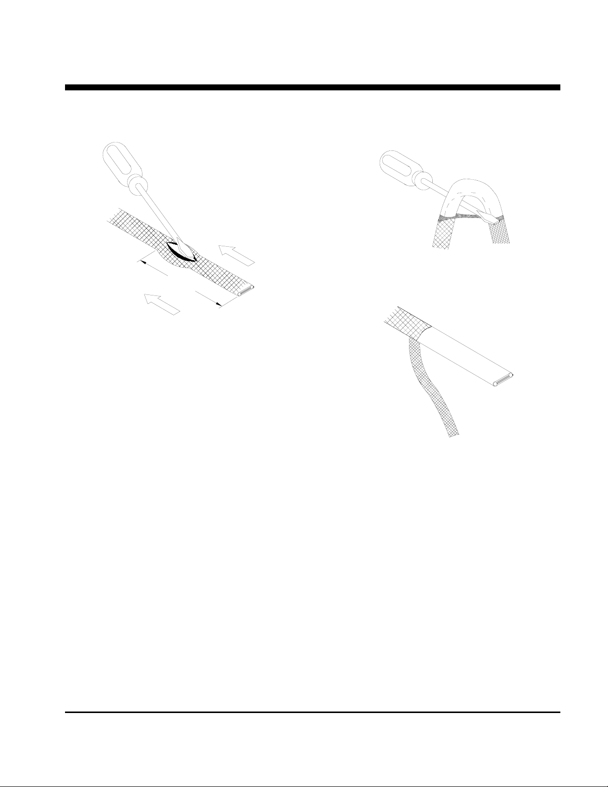
BRAIDED PRODUCTS
see step 1 for the
correct dimensions.
For External Braid Connection:
Move braid back 305mm (12”) to create a bulge.
For Internal Braid Connection:
Move braid back 127mm (5”) to create a bulge.
At the bulge, separate the braid to make an
opening.
While bending the heater cable, work it through
the braid opening.
Pull the braid tight.
Proceed to “LT, CLT & HLT Products”, sheet 5.
P.O. BOX 726 TULSA, OK 74101 TEL 918-627-5530 FAX 918-641-7336 www.nelsonheaters.com
GA-1866 Rev. 7
Sheet 3 of 8
January 2010
Page 18
NELSON™ HEAT TRACING SYSTEMS
ALT-BS SPLICE CONNECTION KIT
INSTALLATION
INSTRUCTIONS
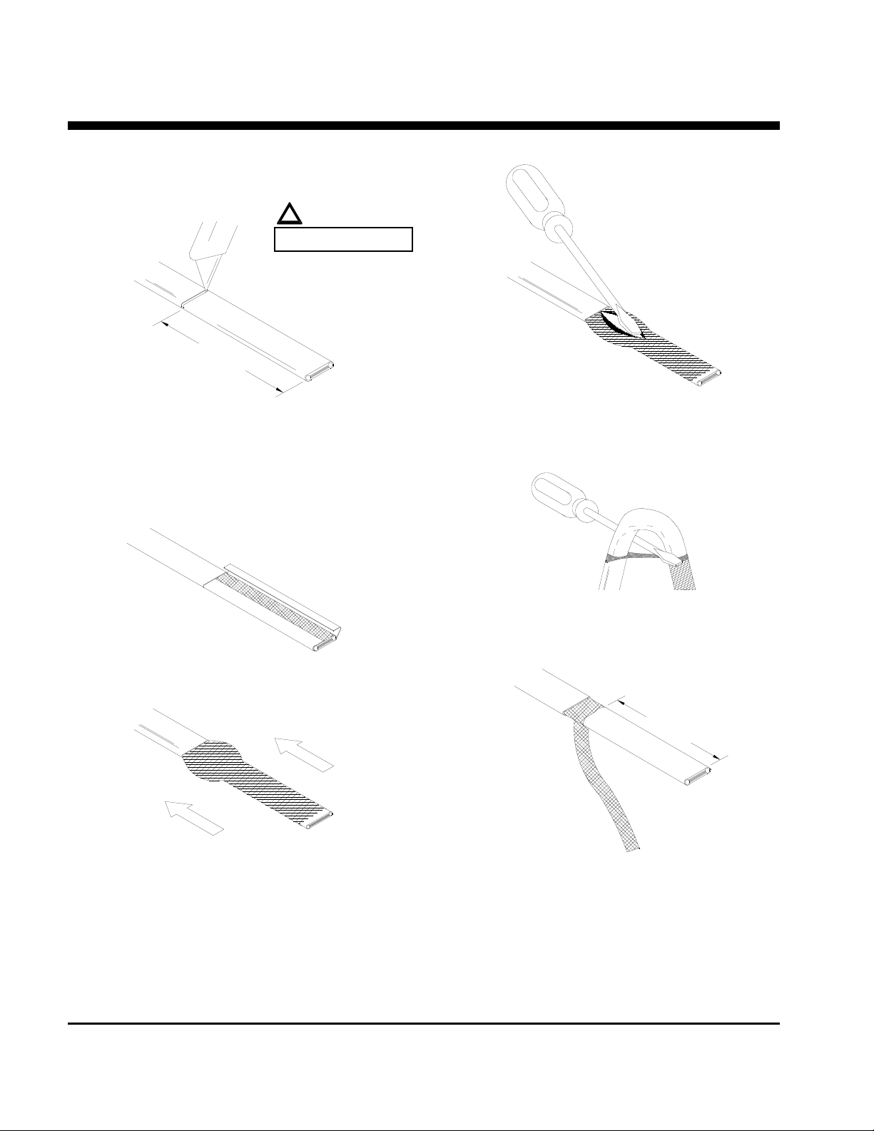
OVERJACKET PRODUCTS
127mm (5")
!
WARNING:
DO NOT CUT BRAID
Lightly cut around heater overjacket 127mm (5")
from the end. Bend cable to break overjacket.
Lightly cut overjacket up the center between first
cut mark and the cable end. Bend cable to break
overjacket.
At the bulge, separate the braid to make an
opening.
Remove overjacket from heater cable.
Move braid back toward the overjacket,
creating a bulge.
While bending the heater cable, work it through
the braid opening.
114mm (4.5")
Pull the braid tight.
Proceed to “LT, CLT & HLT Products”,
sheet 5.
P.O. BOX 726 TULSA, OK 74101 TEL 918-627-5530 FAX 918-641-7336 www.nelsonheaters.com
GA-1866 Rev. 7
Sheet 4 of 8
January 2010
Page 19
NELSON™ HEAT TRACING SYSTEMS
ALT-BS SPLICE CONNECTION KIT
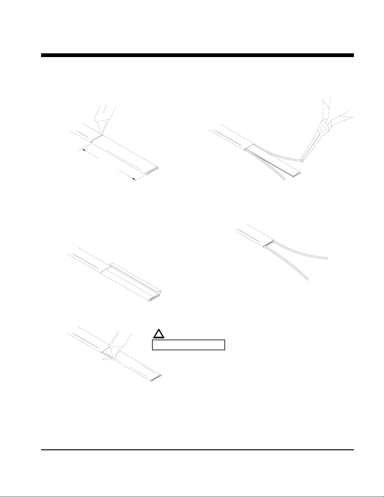
FOR ALL NELSON LT, CLT & HLT PRODUCTS
(See sheet 6 for an alternate method of HLT products)
102mm (4")
INSTALLATION
INSTRUCTIONS
Lightly cut around heater outer jacket 102mm
(4") from the end. Bend cable to break outer
jacket.
Lightly cut the outer jacket up the center between
the first cut mark & the cable end. Bend cable to
break outer jacket.
Remove the jacket from the heater cable.
!
WARNING:
DO NOT CUT BUS WIRES
Starting at the end, pull each bus wire away from
the core.
Remove exposed core material.
Cut 6mm (0.25") off the end of each bus wire.
Proceed to “Power Termination”, sheet 7.
Shave the core material from the outside of each
bus wire.
P.O. BOX 726 TULSA, OK 74101 TEL 918-627-5530 FAX 918-641-7336 www.nelsonheaters.com
GA-1866 Rev. 7
Sheet 5 of 8
January 2010
Page 20
NELSON™ HEAT TRACING SYSTEMS
ALT-BS SPLICE CONNECTION KIT
INSTALLATION
INSTRUCTIONS
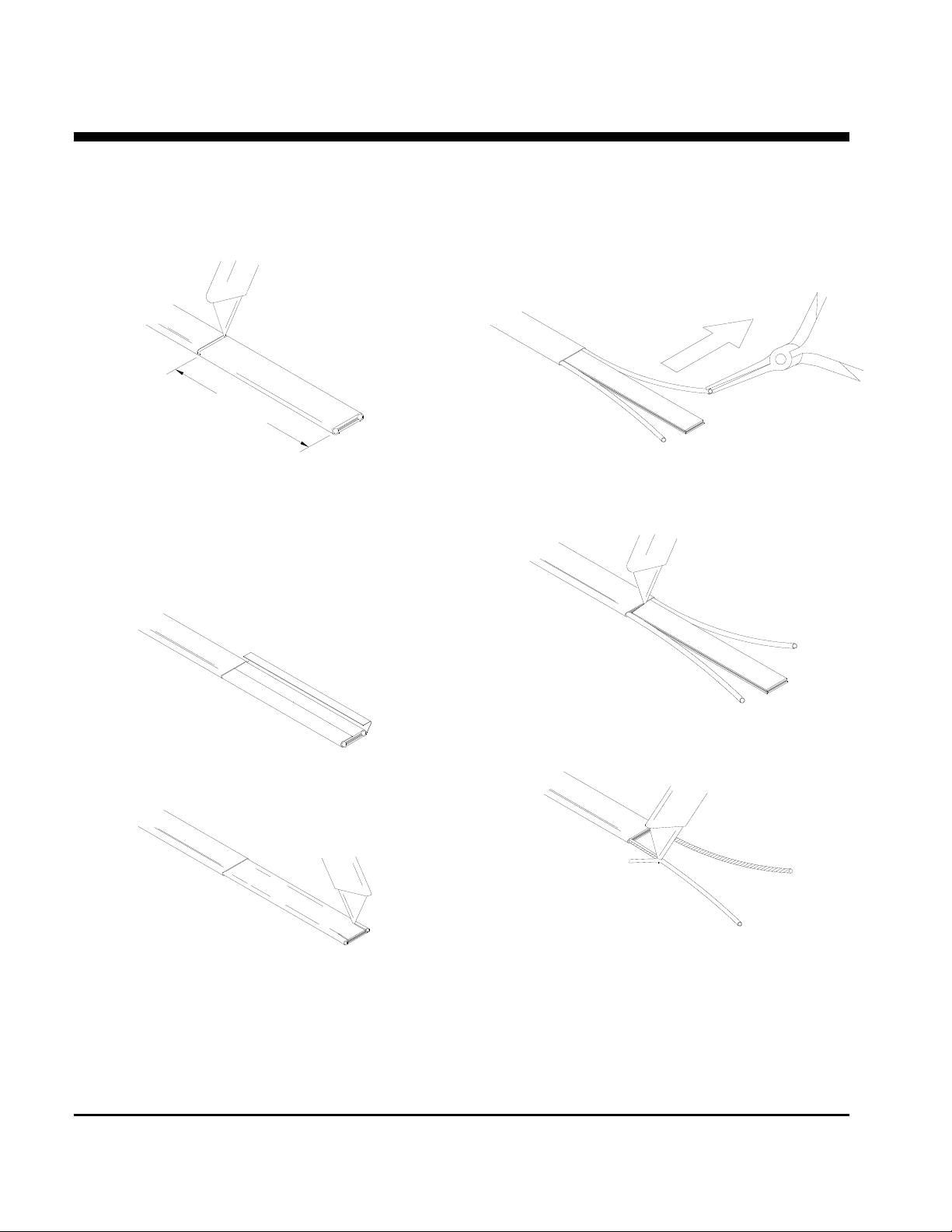
HLT PRODUCTS
ALTERNATE METHOD
102mm (4")
Lightly cut around heater outer jacket 102mm
(4") from the end. Bend cable to break outer
jacket.
Lightly cut the outer jacket up the center between
the first cut mark & the cable end. Bend cable to
break outer jacket.
Starting at the end, in the same plane as the
cable, pull each bus wire away from the core.
Remove the exposed core material.
Remove the jacket from the heater cable.
Make a cut inside each bus wire.
Remove the remaining core material from the
outside of each bus wire.
Cut 6mm (0.25") off the end of each bus wire.
Proceed to “Power Termination”, sheet 7.
P.O. BOX 726 TULSA, OK 74101 TEL 918-627-5530 FAX 918-641-7336 www.nelsonheaters.com
GA-1866 Rev. 7
Sheet 6 of 8
January 2010
Page 21
NELSON™ HEAT TRACING SYSTEMS
ALT-BS SPLICE CONNECTION KIT
INSTALLATION
INSTRUCTIONS
POWER TERMINATION
apply silicone here
!
WARNINGS:
Bus wires must not touch or cross while
inserting into power termination.
Only power terminations specifically
approved for the vendor’s style and type of
heater cable must be used.
Insert bus wires into power termination.
Squeeze power termination opening and fill with
silicone.
13mm (0.5")
Push power termination to overlap jacket.
Proceed to
“Power Termination”
, sheet 8.
P.O. BOX 726 TULSA, OK 74101 TEL 918-627-5530 FAX 918-641-7336 www.nelsonheaters.com
GA-1866 Rev. 7
Sheet 7 of 8
January 2010
Page 22
NELSON™ HEAT TRACING SYSTEMS
ALT-BS SPLICE CONNECTION KIT
POWER CONNECTION
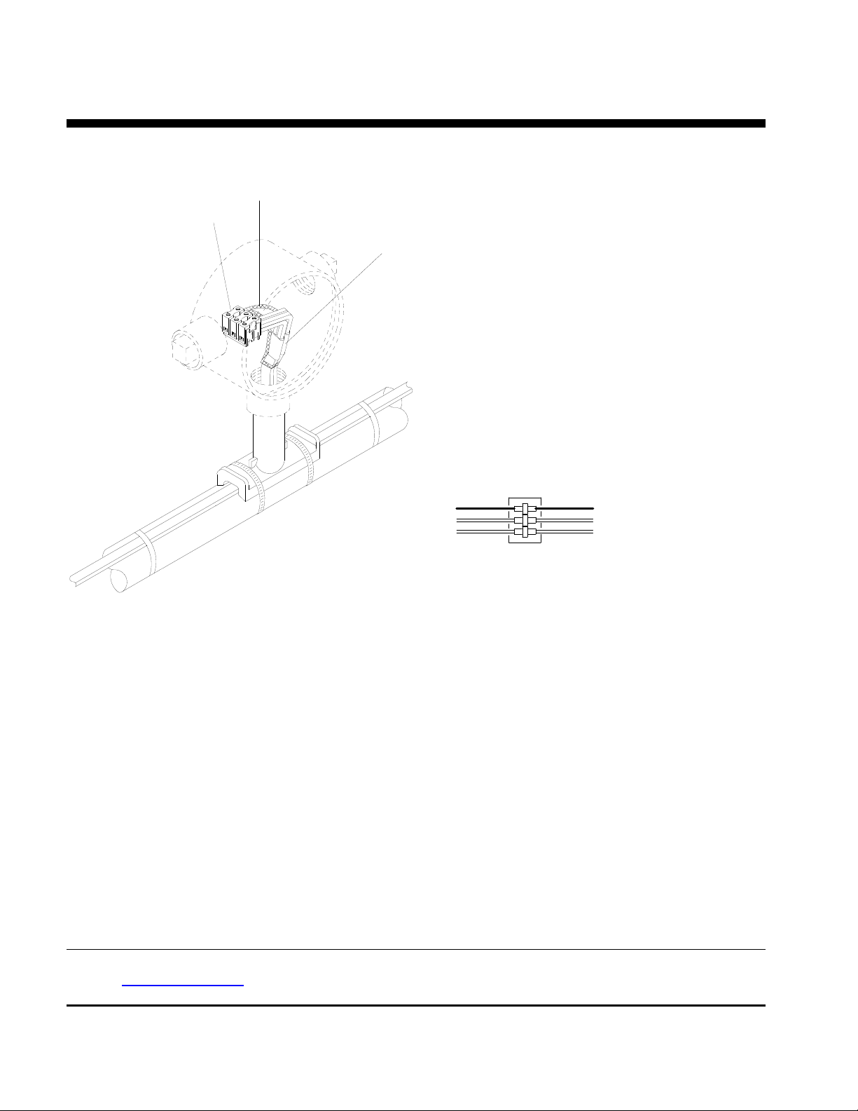
Braid
Terminal Block
Power Terminations
Terminal Block Connection
INSTALLATION
INSTRUCTIONS
Braid
Heater Cable
Braid
Heater Cable
Note: This detail shows internal grounding of braid.
Slide washer over heater cable and position at the sealing grommet.
Secure junction box onto stand-off until tightly fitted. DO NOT OVER TIGHTEN.
Connect bus and power wiring to the terminal block.
See diagram above.
Ground connection:
For External Ground Connected Heaters:
Connect braid from both heater cables to the stand-off using the ground screw. See diagram on sheet 1.
For Internal Ground Connected Heaters:
Connect braid from both heater cables to the terminal block. See diagram above.
For Overjacket J or JT Products only:
Apply silicone at point braid leaves the overjacket.
Push all wires, both heater cables and terminal block inside junction box.
Install box cover gasket and box cover onto junction box.
Nelson Heat Tracing Systems products are supplied with a limited warranty. Complete Terms and Conditions may be found on Nelson's
website at www.nelsonheaters.com
P.O. BOX 726 TULSA, OK 74101 TEL 918-627-5530 FAX 918-641-7336 www.nelsonheaters.com
GA-1866 Rev. 7
Sheet 8 of 8
January 2010
.
Page 23
NELSON™ HEAT TRACING SYSTEMS
ALT-BY TEE SPLICE CONNECTION KIT
INSTALLATION
INSTRUCTIONS
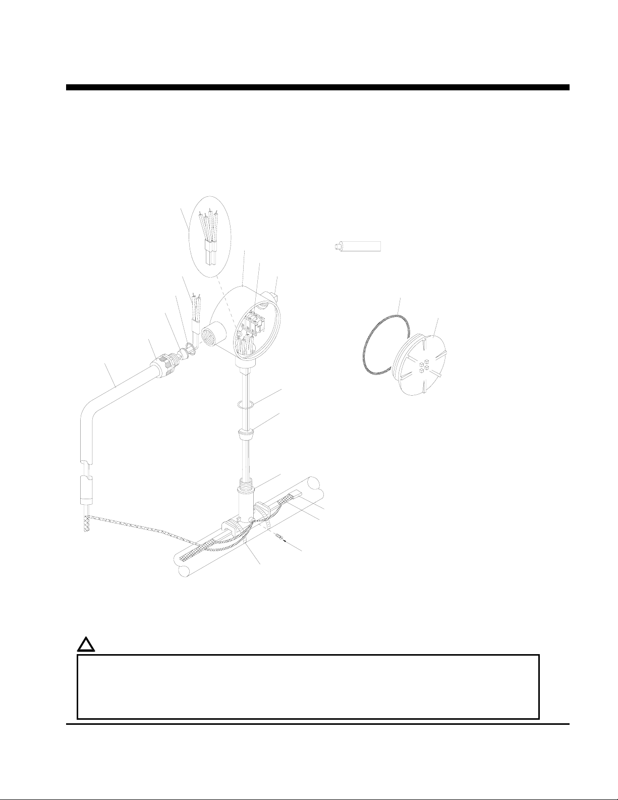
DESCRIPTION
The ALT-BY Tee Splice Connection Kit is constructed of
cast aluminum for use with all versions of Nelson Heat
Tracing Systems’ LT, CLT, HLT and NC heater cables.
Compatible for use with any vendor’s heater cables
smaller than 11mm (0.44”) diameter.
Power Terminations (2)
Junction Box
Terminal Block
Power Termination (1)
Sealing Grommet
J-Grommet - Overjacket Products
B-Grommet - Base Products
Connection Fitting
Flex Tubing
Washer (metal)
Conduit Plug
Washer (metal)
KIT CONTENTS
1 Junction Box 3 Power Terminations
1 Terminal Block 2 Washers
1 Conduit Plug 1 Ground Screw
2 Sealing Grommets 2 End Seals
1 Stand-off 1 Tube of Silicone
1 Flex Tubing 2 Pipe Clamps
1 Connection Fitting
Silicone
Box Cover Gasket
Box Cover
Sealing Grommet
U-Grommet - Double Entry, NC, or any other heater
Stand-off
*ITEMS NOT INCLUDED IN KIT
End Seal
*Heater Cable; braid optional
(see warnings below)
Ground Screw
(for braided heater cables only)
Pipe Clamps
Note: This detail shows external grounding of braid. For internal ground of braid (overjacket
products), see sheet 8.
!
WARNINGS:
• Canadian Div. 2 Hazardous installations must use internal ground connection of braid. See sheet 8.
• Article 427 of the National Electric Code requires that all heaters shall have metal coverings and be
provided with branch circuit ground-fault protection.
• If nuisance tripping of ground fault breakers occurs due to condensation in connection box, electrical
connection should be moisture proofed by use of a coating or sealant.
P.O. BOX 726 TULSA, OK 74101 TEL 918-627-5530 FAX 918-641-7336 www.nelsonheaters.com
GA-1867 Rev. 5
Sheet 1 of 8
September 2005
Page 24
NELSON™ HEAT TRACING SYSTEMS
ALT-BY TEE SPLICE CONNECTION KIT
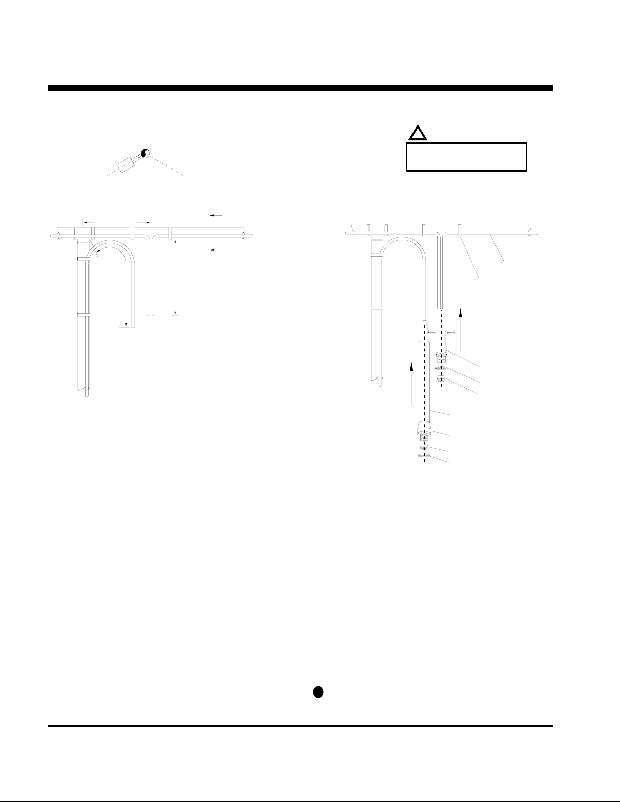
Section View A A
(recommend installing at the
4 or 8 o'clock positions.)
!
Do not place pipe clamps
over the heater cable.
INSTALLATION
INSTRUCTIONS
WARNING:
8 o'clock
4 o'clock
STAND-OFF POSITIONING
203mm (8")
305mm (12")
457mm (18")
*ITEMS NOT INCLUDED IN KIT
A
A
n Cut heater cables to lengths shown.
o External Braid Connection - CB Products
only:
• Remove braid from heater cables, back to the
point the cables leave the pipe. See Sheet 3.
• Proceed to step 3 below.
Internal Braid Connection - CB, J or JT
Products:
Proceed to step 3 below.
p Push the two 305mm (12”) heater cables through
the bottom opening of stand-off.
q Place stand-off on pipe and fasten with pipe
clamps.
r Slide the large opening sealing grommet over the
two heater cables and position inside stand-off
opening.
Pipe Tee
*Heater Cable
*Fiberglass Tape
Stand-off
Gasket
Sealing Grommet
Flex Tubing
Connection Fitting
Sealing Grommet
Washer; metal
s Apply silicone around heater cables on top of the
sealing grommet and fill any voids in sealing
grommet.
t Install flex tubing assembly over the 457mm (18”)
heater cable and tape at pipe tee with fiberglass
tape (not included in kit).
u Slide the gasket and small opening sealing
grommet over the single heater cable and
position inside connection fitting.
v Apply silicone around heater cable at top of the
sealing grommet and fill any voids in sealing
grommet.
w Prepare heater cables for power termination:
for braided products, see sheet 3.
for overjacket products, see sheet 4.
for base products, see sheet 5.
11
Terminate heater cables, see sheet 7.
P.O. BOX 726 TULSA, OK 74101 TEL 918-627-5530 FAX 918-641-7336 www.nelsonheaters.com
GA-1867 Rev. 5
Sheet 2 of 8
September 2005
Page 25
NELSON™ HEAT TRACING SYSTEMS
ALT-BY TEE SPLICE CONNECTION KIT
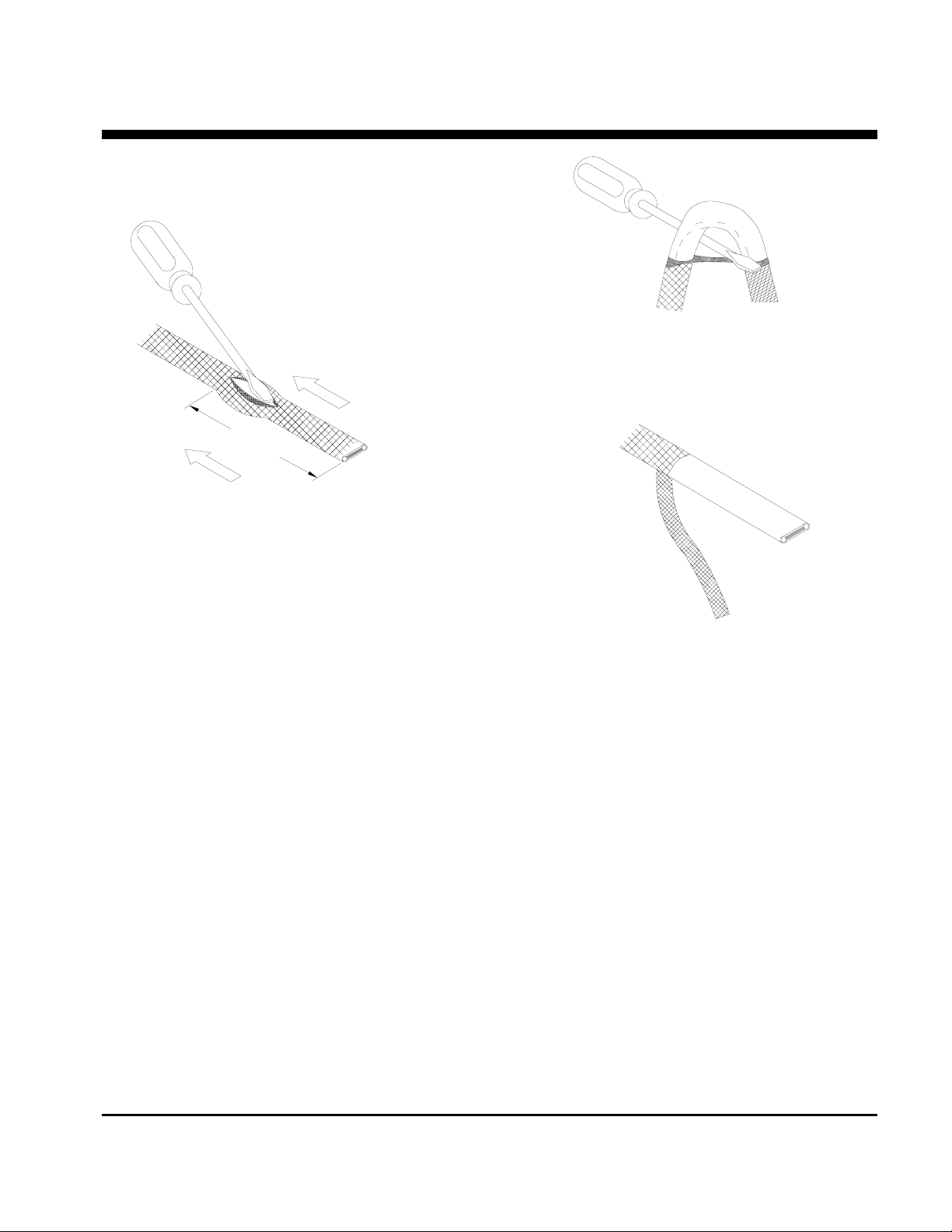
BRAIDED PRODUCTS
p While bending the heater cable, work it through
the braid opening.
see step 1 for the
correct dimensions.
INSTALLATION
INSTRUCTIONS
n For External Braid Connection:
For heater cable going through the flex tubing move braid back 457mm (18”) to create a bulge.
For heater cables going through the stand-off -
move braid back 305mm (12”) to create a bulge.
For Internal Braid Connection:
Move braid back 127mm (5”) to create a bulge.
o At the bulge, separate the braid to make an
opening.
q Pull the braid tight.
r Proceed to “LT, CLT & HLT Products”, sheet 5.
P.O. BOX 726 TULSA, OK 74101 TEL 918-627-5530 FAX 918-641-7336 www.nelsonheaters.com
GA-1867 Rev. 5
Sheet 3 of 8
September 2005
Page 26
NELSON™ HEAT TRACING SYSTEMS
ALT-BY TEE SPLICE CONNECTION KIT
INSTALLATION
INSTRUCTIONS
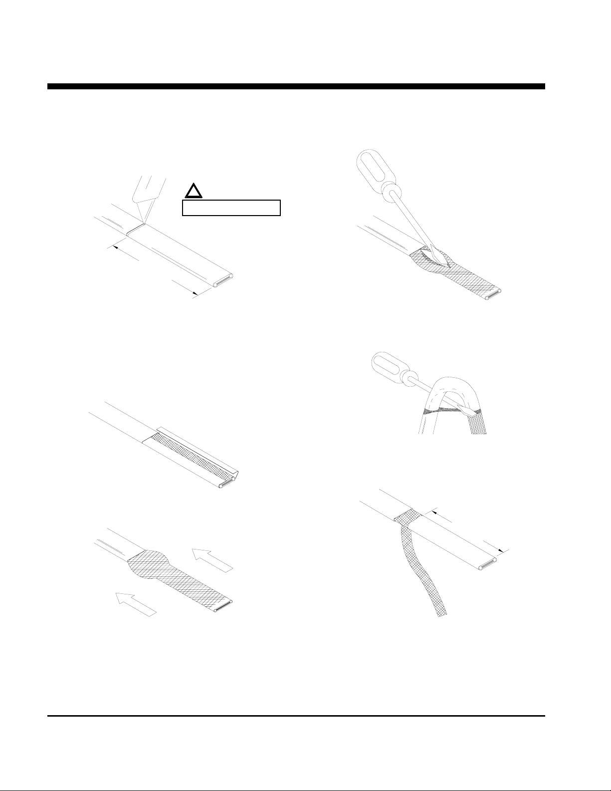
OVERJACKET PRODUCTS
!
WARNING:
DO NOT CUT BRAID
127mm (5")
n Lightly cut around heater overjacket 127mm
(5") from the end. Bend cable to break
overjacket.
o Lightly cut overjacket up the center between
first cut mark and the cable end. Bend cable to
break overjacket.
r At the bulge, separate the braid to make an
opening.
p Remove overjacket from heater cable.
q Move braid back toward the overjacket,
creating a bulge.
s While bending the heater cable, work it through
the braid opening.
114mm (4.5")
t Pull the braid tight.
u Proceed to “LT, CLT & HLT Products”, sheet 5.
P.O. BOX 726 TULSA, OK 74101 TEL 918-627-5530 FAX 918-641-7336 www.nelsonheaters.com
GA-1867 Rev. 5
Sheet 4 of 8
September 2005
Page 27
NELSON™ HEAT TRACING SYSTEMS
ALT-BY TEE SPLICE CONNECTION KIT
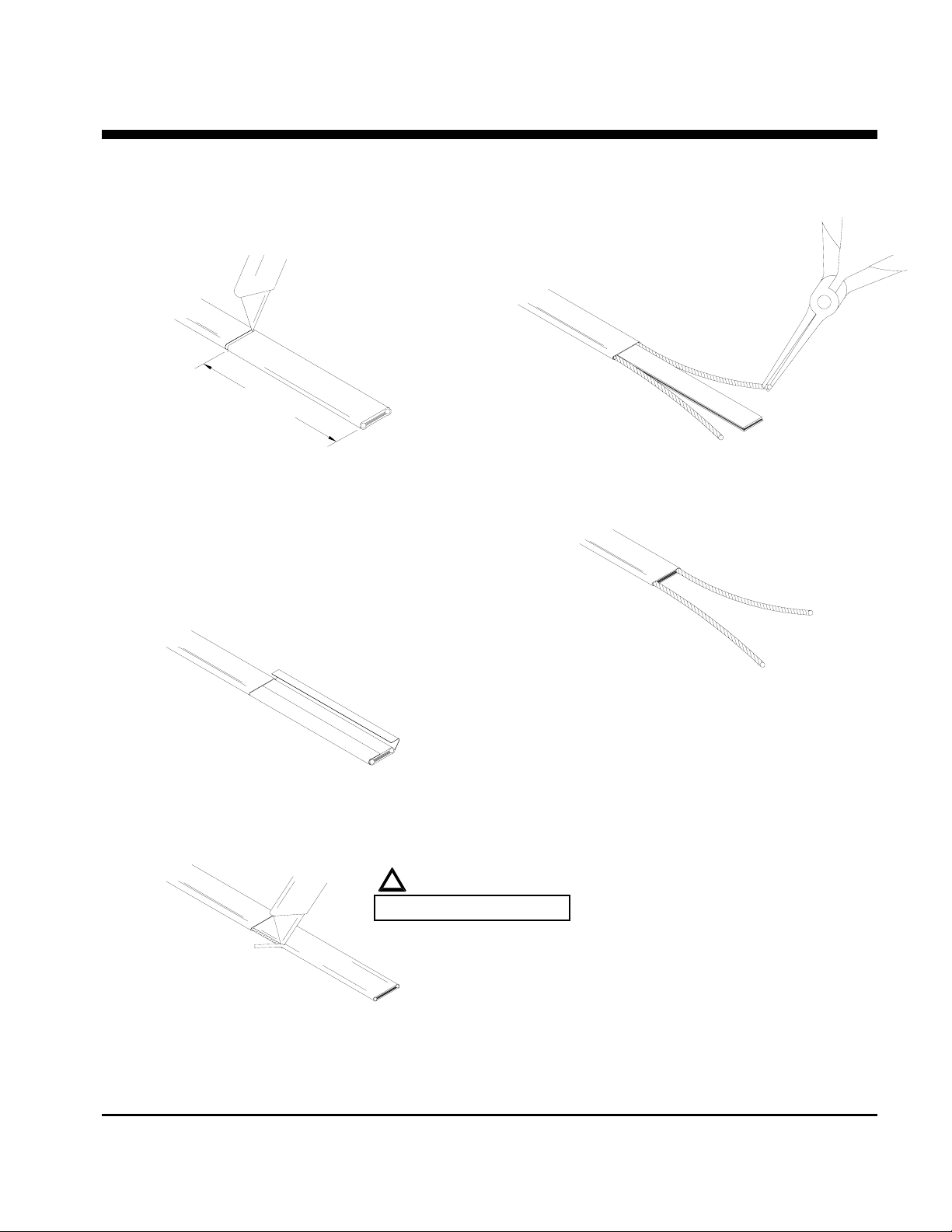
FOR ALL NELSON LT, CLT & HLT PRODUCTS
(See sheet 6 for an alternate method of HLT products.)
102mm (4")
INSTALLATION
INSTRUCTIONS
n Lightly cut around heater outer jacket 102mm
(4") from the end. Bend cable to break outer
jacket.
o Lightly cut the outer jacket up the center
between the first cut mark & the cable end.
Bend cable to break outer jacket.
p Remove the jacket from the heater cable.
!
WARNING:
DO NOT CUT BUS WIRES.
r Starting at the end, pull each bus wire away
from the core material.
s Remove exposed core material.
t Cut 6mm (0.25") off the end of each bus wire.
u Proceed to “Power Termination”, sheet 7.
q Shave the core material from the outside of
each bus wire.
P.O. BOX 726 TULSA, OK 74101 TEL 918-627-5530 FAX 918-641-7336 www.nelsonheaters.com
GA-1867 Rev. 5
Sheet 5 of 8
September 2005
Page 28
NELSON™ HEAT TRACING SYSTEMS
ALT-BY TEE SPLICE CONNECTION KIT
INSTALLATION
INSTRUCTIONS
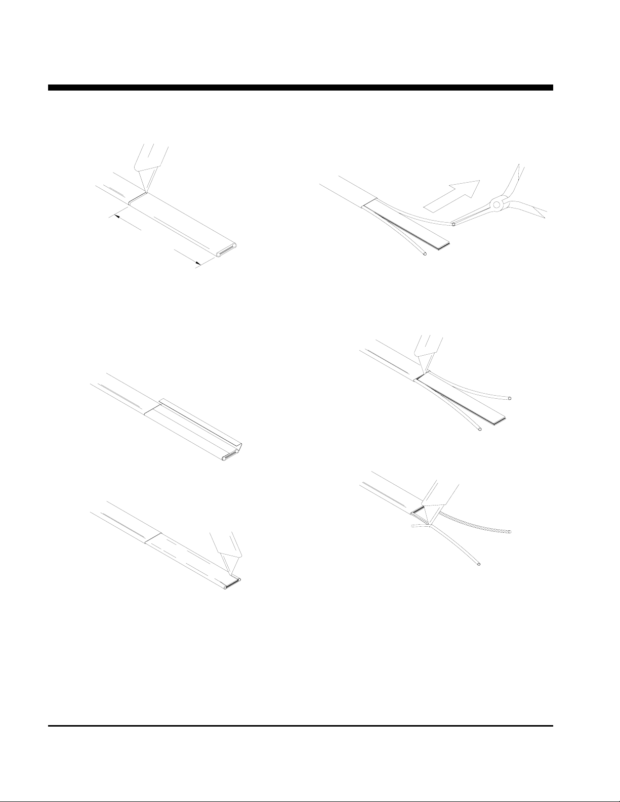
HLT PRODUCTS
ALTERNATE METHOD
102mm (4")
n Lightly cut around heater outer jacket 102mm
(4") from the end. Bend cable to break outer
jacket.
o Lightly cut the outer jacket up the center
between the first cut mark & the cable end.
Bend cable to break outer jacket.
r Starting at the end, in the same plane as the
cable, pull each bus wire away from the core
material.
p Remove the jacket from the heater cable.
q Make a cut inside each bus wire.
s Remove exposed core material.
t Remove the remaining core material off the
outside of each bus wire.
u Cut 6mm (0.25") off the end of each bus wire.
v Proceed to “Power Termination”, sheet 7.
P.O. BOX 726 TULSA, OK 74101 TEL 918-627-5530 FAX 918-641-7336 www.nelsonheaters.com
GA-1867 Rev. 5
Sheet 6 of 8
September 2005
Page 29
NELSON™ HEAT TRACING SYSTEMS
ALT-BY TEE SPLICE CONNECTION KIT
INSTALLATION
INSTRUCTIONS
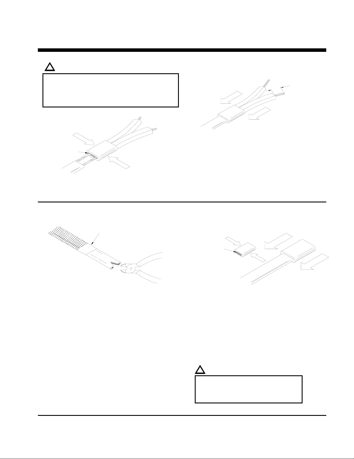
POWER TERMINATION
!
WARNINGS:
• Bus wires must not touch or cross while inserting
into power termination.
• Only power terminations / end seals specifically
approved for the vendor’s style and type of heater
cable must be used.
apply silicone here
n Insert bus wires into power termination.
o Squeeze power termination opening and fill
with silicone.
END SEAL
Fiberglass Tape
(not included in kit)
13mm (0.5")
p Push power termination to overlap jacket.
q At this point, if you’re installing the end seal,
see the “End Seal” section below. Otherwise,
proceed to “Power Connection”, sheet 8.
n Braided Products:
Cut braid back 25mm (1") & tape in place with
fiberglass tape; not included in kit.
Overjacket Products:
Remove 13mm (0.5") of overjacket exposing
the braid, then remove the 13mm (0.5”) of
exposed braid.
o Make a 10mm (0.4") cut at the end of the
heater cable.
apply silicone here
p Squeeze end seal and fill with silicone.
q Push end seal over the heater cable.
Overjacket Products:
The end seal should overlap the overjacket.
r The silicone will set up in about 30 minutes with
a complete cure after 24 hours.
s Proceed to “Power Connection”, sheet 8.
!
WARNINGS:
• Do not megger or hi-pot until silicone
is completely cured.
• Braid must be kept away from bus
wires or shorting will occur.
P.O. BOX 726 TULSA, OK 74101 TEL 918-627-5530 FAX 918-641-7336 www.nelsonheaters.com
GA-1867 Rev. 5
Sheet 7 of 8
September 2005
Page 30
NELSON™ HEAT TRACING SYSTEMS
ALT-BY TEE SPLICE CONNECTION KIT
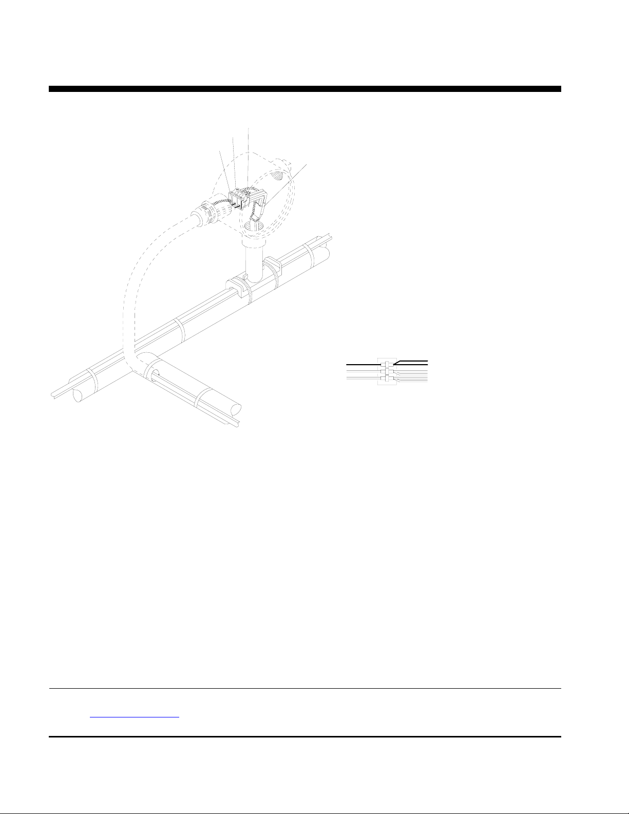
POWER CONNECTION
Braid
Terminal Block
Ground Wire
Power Terminations
TERMINAL BLOCK CONNECTIONS
INSTALLATION
INSTRUCTIONS
Braid
Heater Cable
Braid
Heater Cable
Note: This detail shows internal grounding of braid.
n Slide washer over the two heater cables and position at the sealing grommet.
o Secure junction box onto stand-off until tightly fitted. DO NOT OVER TIGHTEN.
p Secure the flex tubing assembly onto the junction box. (Braid if present, should be separated from the
heater cable in a pigtail as it leaves the sealing grommet entering the enclosure.)
q Ground Connection:
For External Ground Connected Heaters:
Connect ground braid from all three heater cables together using the ground screw. See diagram on sheet 1.
For Internal Ground Connected Heaters:
Connect ground braid and ground wire from all heater cables to the terminal block. See diagram above.
r For Overjacket J or JT Products only:
Apply Silicone at point braid leaves the overjacket.
s Push all wires, cables and the terminal block inside junction box.
t Place box cover and box cover gasket onto the junction box.
Nelson Heat Tracing Systems products are supplied with a limited warranty. Complete Terms and Conditions may be found on Nelson's
website at
www.nelsonheaters.com.
P.O. BOX 726 TULSA, OK 74101 TEL 918-627-5530 FAX 918-641-7336 www.nelsonheaters.com
GA-1867 Rev. 5
Sheet 8 of 8
September 2005
Page 31
NELSON™ HEAT TRACING SYSTEMS
INSTALLATION
ALT-L SERIES END OF CIRCUIT LIGHT KIT
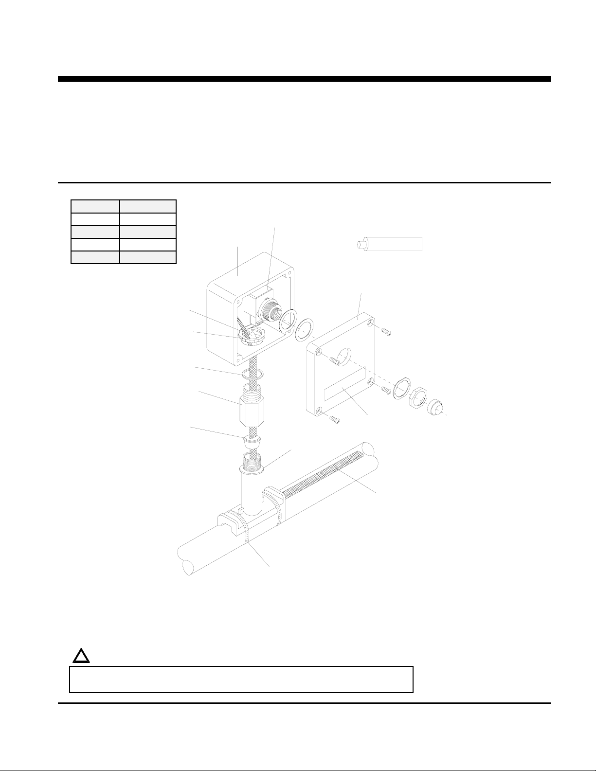
DESCRIPTION
The ALT-L Series End of Circuit Light Kit is constructed
of aluminum. For use with all versions of LT, CLT, HLT
and NC heater cables. Compatible for use with any
vendor’s heater cables smaller than 11mm (.44”)
diameter.
Voltage Kit Cat. #
120V ALT-L120
208V ALT-L208
240V ALT-L240
277V ALT-L277
Power Termination
Conduit Locknut
Light Assembly
Junction Box
KIT CONTENTS
1 Junction Box 1 Power Termination
1 Conduit Locknut 1 Box Adapter
1 Sealing Grommet 1 Gasket
1 Stand-off 1 Tube of Silicon e
1 Ground Screw 2 Pipe Clamps
1 Light Assembly 1 Piece of Shrink Tube
1 Caution Label
Box Cover
INSTRUCTIONS
Silicone
Gasket
Box Adapter
Sealing Grommet
J-Grommet - Overjacket Products
B-Grommet - Base Products
U-Grommet - NC or any other special
construction heaters
Stand-off
Pipe Clamp
Note: For internal grounding of braid see sheet 8.
Label
*Heater Cable
(see warning below)
*ITEMS NOT INCLUDED IN KIT
!
WARNING:
Article 427-22 of the National Electrical Code requires that all heaters shall have
metal coverings and be provided with branch circuit ground-fault protection.
P.O. BOX 726 TULSA, OK 74101 TEL 918-627-5530 FAX 918-641-7336 www.nelsonheaters.com
GA-2027 Rev. 1
September 2005
Sheet 1 of 8
Page 32
NELSON™ HEAT TRACING SYSTEMS
A
INSTALLATION
ALT-L SERIES END OF CIRCUIT LIGHT KIT
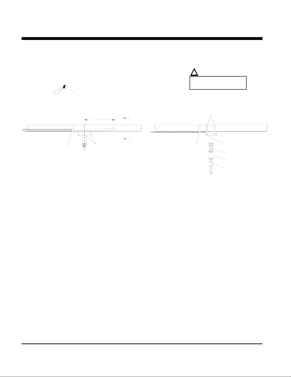
STAND-OFF POSITIONING
Section View A
(recommend installing at the
4 or 8 o'clock positions.)
8 o'clock
4 o'clock
254mm (10")
A
A
Fiberglass Tape
(not included in kit)
Stand-off
Fiberglass Tape
(not included in kit)
INSTRUCTIONS
!
WARNING:
Do not place pipe clamps
over the heater cable.
Pipe Clamps
Stand-off
Sealing Grommet
Box Adapter
Power Termination
n Mark pipe where stand-off will be mounted.
o Push heater cable through bottom opening of stand-off.
p Slide the sealing grommet over the heater cable and position inside stand-off opening:
for Braided “CB” Products:
See “Grommet Installation for Braided “CB” Products”, sheet 3.
for Overjacket “J” or “JT” Products
Proceed with step 4 below.
q Apply silicone around the heater cable on top of the sealing grommet and fill any voids in sealing grommet.
r Slide the box adapter over the heater cable and tighten securely to stand-off.
s Prepare heater cable for power termination:
for Braided “CB” Products, see sheet 3.
for Overjacket “J” or “JT” Products, see sheet 4.
t Terminate heater cable, see sheet 7.
P.O. BOX 726 TULSA, OK 74101 TEL 918-627-5530 FAX 918-641-7336 www.nelsonheaters.com
GA-2027 Rev. 1
Sheet 2 of 8
September 2005
Page 33
NELSON™ HEAT TRACING SYSTEMS
INSTALLATION
ALT-L SERIES END OF CIRCUIT LIGHT KIT
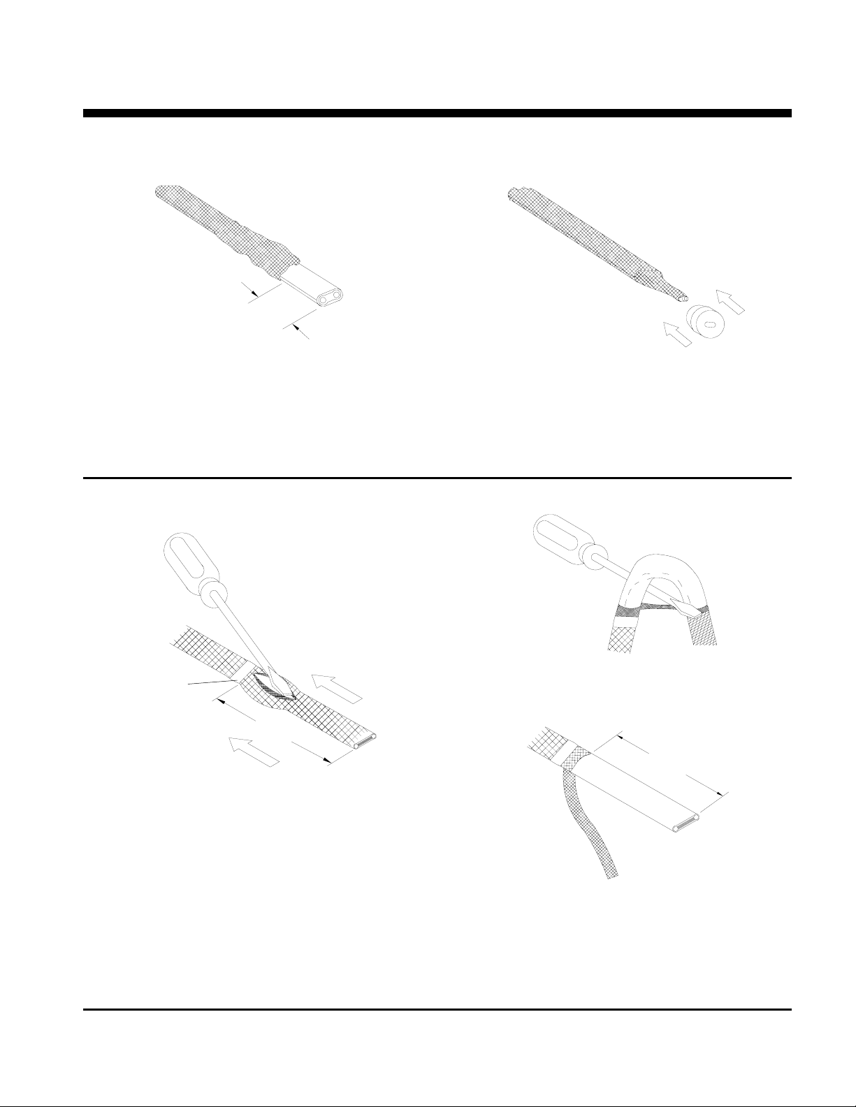
SEALING GROMMET INSTALLATION FOR BRAIDED “CB” PRODUCTS
13mm (.5")
n Slide braid back, allowing at least 13mm (.5”) of
heater cable exposed.
o Cut and remove 13mm (.5”) of heater cable.
BRAIDED “CB” PRODUCTS
p Slide braid back over heater cable and twist
excess braid into a pigtail.
q Slide the sealing grommet over the heater cable
and position inside stand-off opening.
r Continue with step 4 on sheet 2.
INSTRUCTIONS
*Fiberglass Tape
(not included in kit)
127mm (5")
q While bending the heater cable, work it through
the braid opening.
114mm (4.5")
n Secure cable braid with fiberglass tape.
o Slide braid back 127mm (5”) to create a bulge.
p At the bulge, separate the braid to make an
opening.
r Pull the braid tight,
s Proceed to “LT, CLT & HLT Products”, sheet 5
P.O. BOX 726 TULSA, OK 74101 TEL 918-627-5530 FAX 918-641-7336 www.nelsonheaters.com
GA-2027 Rev. 1
September 2005
Sheet 3 of 8
Page 34
NELSON™ HEAT TRACING SYSTEMS
INSTALLATION
ALT-L SERIES END OF CIRCUIT LIGHT KIT
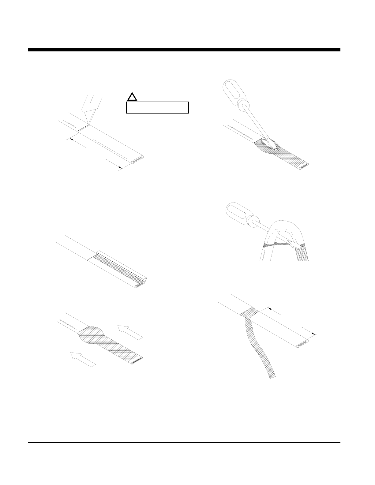
OVERJACKET “J” or “JT” PRODUCTS
127mm (5")
!
WARNING:
DO NOT CUT BRAID
n Lightly cut around cable overjacket 127mm (5")
from the end. Bend cable to break the
overjacket.
o Lightly cut overjacket up the center between first
cut mark and the cable end. Bend cable to break
the overjacket.
r At the bulge, separate the braid to make an
opening.
INSTRUCTIONS
p Remove overjacket from heater cable.
q Move braid back toward the overjacket,
creating a bulge.
s While bending the heater cable, work it through
the braid opening.
114mm (4.5")
Pull the braid tight.
t
u Proceed to “LT, CLT & HLT Products”, sheet 5.
P.O. BOX 726 TULSA, OK 74101 TEL 918-627-5530 FAX 918-641-7336 www.nelsonheaters.com
GA-2027 Rev. 1
Sheet 4 of 8
September 2005
Page 35
NELSON™ HEAT TRACING SYSTEMS
INSTALLATION
ALT-L SERIES END OF CIRCUIT LIGHT KIT
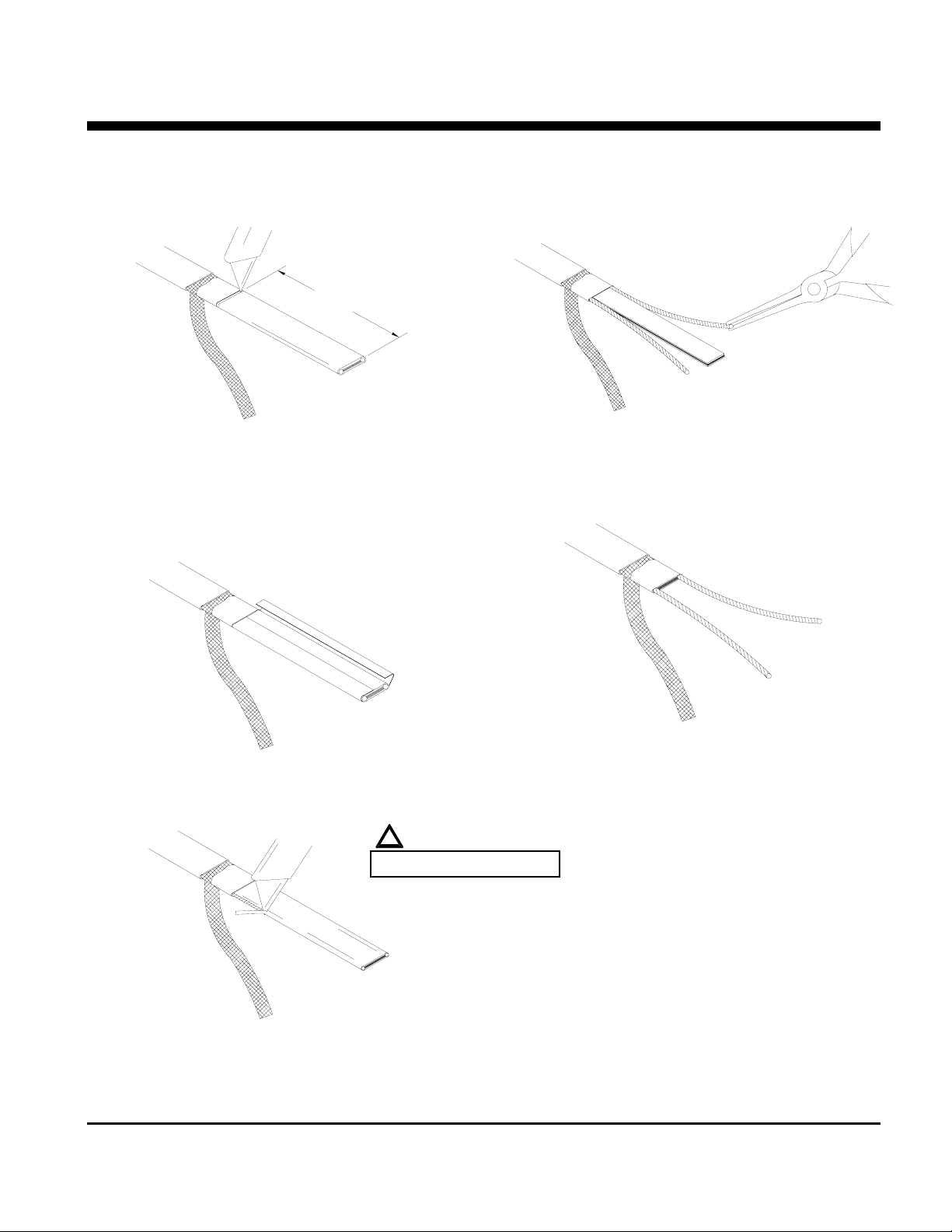
FOR ALL NELSON LT, CLT & HLT PRODUCTS
(See sheet 6 for an alternate stripping method for HLT products.)
102mm (4")
n Lightly cut around cable outer jacket 102mm (4")
from the end. Bend cable to break outer jacket.
o Lightly cut the outer jacket up the center
between the first cut mark & the cable end. Bend
cable to break outer jacket.
r Starting at the end, pull each bus wire away from
the core material.
s Remove exposed core material.
INSTRUCTIONS
t Cut 6mm (0.25") off the end of each bus wire.
u Proceed to “Power Termination”, sheet 7.
p Remove the jacket from the heater cable.
!
WARNING:
q Shave the core material from the outside of each
bus wire.
P.O. BOX 726 TULSA, OK 74101 TEL 918-627-5530 FAX 918-641-7336 www.nelsonheaters.com
GA-2027 Rev. 1
September 2005
Sheet 5 of 8
Page 36
NELSON™ HEAT TRACING SYSTEMS
INSTALLATION
ALT-L SERIES END OF CIRCUIT LIGHT KIT
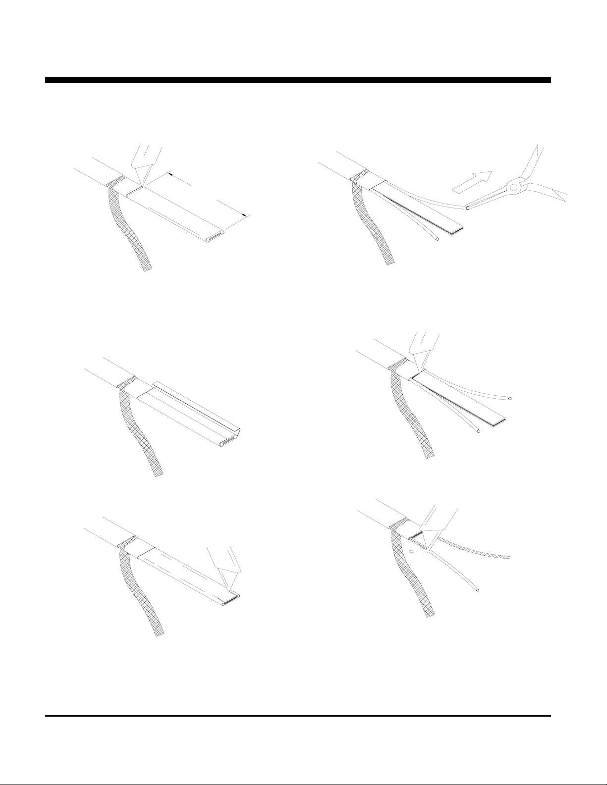
HLT PRODUCTS ALTERNATE STRIPPING METHOD
102mm (4")
n Lightly cut around cable outer jacket 102mm (4")
from the end. Bend cable to break outer jacket.
o Lightly cut the outer jacket up the center
between the first cut mark & the cable end. Bend
cable to break outer jacket.
r Starting at the end, in the same plane as the
cable, pull each bus wire away from the core
material.
INSTRUCTIONS
p Remove the jacket from the heater cable.
q Make a cut inside each bus wire.
s Remove the exposed core material.
t Remove the remaining core material off the
outside of each bus wire.
u Cut 6mm (0.25") off the end of each bus wire.
v Proceed to “Power Termination”, sheet 7.
P.O. BOX 726 TULSA, OK 74101 TEL 918-627-5530 FAX 918-641-7336 www.nelsonheaters.com
GA-2027 Rev. 1
Sheet 6 of 8
September 2005
Page 37
NELSON™ HEAT TRACING SYSTEMS
g
INSTALLATION
ALT-L SERIES END OF CIRCUIT LIGHT KIT
POWER TERMINATION
!
WARNING:
Bus wires must not touch or cross
while insertin
apply silicone here
into power termination.
n Insert bus wires into power termination.
o Squeeze power termination opening and fill with
silicone.
p Push power termination to overlap jacket.
q The silicone will set up in about 30 minutes with
a complete cure after 24 hours.
r Proceed to “Electrical Connection”, sheet 8.
INSTRUCTIONS
13mm (.5")
P.O. BOX 726 TULSA, OK 74101 TEL 918-627-5530 FAX 918-641-7336 www.nelsonheaters.com
GA-2027 Rev. 1
September 2005
Sheet 7 of 8
Page 38
NELSON™ HEAT TRACING SYSTEMS
INSTALLATION
ALT-L SERIES END OF CIRCUIT LIGHT KIT
ELECTRICAL CONNECTION
Power Termination
Heater Cable
Light Assembly
Ground Braid
Piece of Shrink Tube
Ground Screw
INSTRUCTIONS
Note: This detail shows internal grounding of braid.
n Place gasket onto the box adapter.
o Position junction box onto the box adapter and secure it with the conduit locknut.
p Place the two black compensating gaskets onto the light assembly base.
q Insert power wires into screw connection of light assembly.
r Slide piece of shrink tube over ground braid.
s Connect ground braid to the ground screw inside the junction box. See diagram above.
t Place the box cover onto the light assembly then install the clear trim washer and secure it with the ring nut.
u Secure the box cover onto the junction box.
Nelson Heat Tracing Systems products are supplied with a limited warranty. Complete Terms and Conditions may be found on Nelson's
website at
P.O. BOX 726 TULSA, OK 74101 TEL 918-627-5530 FAX 918-641-7336 www.nelsonheaters.com
GA-2027 Rev. 1
Sheet 8 of 8
September 2005
www.nelsonheaters.com.
Page 39
NELSON™ HEAT TRACING SYSTEMS
INSTALLATION
ALT-LP POWER CONNECTION KIT WITHOUT ENCLOSURE INSTRUCTIONS
DESCRIPTION
The ALT-LP Power Connection Kit without Enclosure is constructed
of cast aluminum for use with all versions of Nelson Heat Tracing
Systems’ LT, HLT & NC heater cables. Compatible for use with any
vendor’s heater cables smaller than 11mm (0.44”) diameter.
*Conduit & Drain
*Power Termination
*Junction Box
*Crimp Connector
*Conduit Plug
*Ground Wire
(for internal grounding of braid only)
Gasket
Box Adapter
KIT CONTENTS
1 Sealing Grommet 1 Gasket
1 Stand-off 1 Tube of Silicone
1 Ground Screw 1 Box Adapter
1 Conduit Locknut
Silicone
*Box Cover Gasket
*Box Cover
**Sealing Grommet
*End Seal
Stand-off
*Pipe Clamp
*Heater Cable; braid optional
(see warnings)
For Braided Heater Cables Only:
Connect braid using the ground screw.
**Sealing Grommets
J-Grommet - Overjacket Products
B-Grommet - Base Products
U-Grommet - Double Entry or non-standard construction
*ITEMS NOT INCLUDED IN KIT
Note: This detail shows external grounding of braid. For internal grounding of braid (overjacket
products), connect to ground screw inside of junction box.
!
WARNINGS:
• Canadian Div. 2 Hazardous installations must use internal ground connection of braid.
• Article 427 of the National Electric Code requires that all heaters shall have metal coverings and be
provided with branch circuit ground-fault protection.
• If nuisance tripping of ground fault breakers occurs due to condensation in junction box, electrical
connections should be moisture proofed by use of a coating or sealant.
PO BOX 726 TULSA, OK 74101 (918) 627-5530 FAX (918) 641-7336 www.nelsonheaters.com
GA-1890 Rev. 5
Sheet 1 of 2
September 2005
Page 40
NELSON™ HEAT TRACING SYSTEMS
*
INSTALLATION
ALT-LP POWER CONNECTION KIT WITHOUT ENCLOSURE INSTRUCTIONS
STAND-OFF POSITIONING
Section View A A
(recommend installing at the
4 or 8 o'clock positions)
8 o'clock
4 o'clock
254mm (10")
A
!
WARNING:
Do not place pipe clamps
over the heater cable.
Pipe Clamps
*Fiberglass Tape
Stand-off
A
*Fiberglass Tape
Braid
*ITEMS NOT INCLUDED IN KIT.
n Mark pipe where stand-off will be mounted.
o For External Braid Connection - CB Products only:
• Remove braid from heater cables, back to the point the cables leave the pipe.
• Proceed to step 3 below.
For Internal Braid Connection - CB, J or JT Products:
• Proceed to step 3 below.
p Push heater cable through the bottom opening of stand-off.
q Place stand-off on pipe and fasten with pipe clamps.
r Slide the sealing grommet over heater cable and position inside stand-off opening.
Stand-off
Sealing Grommet
Box Adapter
Gasket
*Power Termination
s Apply silicone around the cable on top of the sealing grommet and fill any voids in sealing grommet.
t Prepare heater cable for power termination using an approved termination kit.
Nelson Heat Tracing Systems products are supplied with a limited warranty. Complete Terms and Conditions may be found on Nelson's
website at
PO BOX 726 TULSA, OK 74101 (918) 627-5530 FAX (918) 641-7336 www.nelsonheaters.com
GA-1890 Rev. 5
Sheet 2 of 2
September 2005
www.nelsonheaters.com.
Page 41
NELSON™ HEAT TRACING SYSTEMS
INSTALLATION
ALT-LPM POWER CONNECTION KIT WITHOUT ENCLOSURE INSTRUCTIONS
DESCRIPTION
The ALT-LPM Power Connection Kit without Enclosure is
constructed of cast aluminum for use with all versions of
Nelson Heat Tracing Systems’ LT, HLT & NC heater cables.
Compatible for use with any vendor’s heater cables smaller
than 11mm (0.44”) diameter. Minimum installation
temperature –40°C (-40°F).
*Conduit & Drain
Power Termination
*Junction Box
Terminal Block
*Conduit Plug
Gasket
KIT CONTENTS
1 Sealing Grommet 1 Power Termination
Stand-off 1 Terminal Block
1
End Seal 1 Gasket
1
Ground Screw 1 Tube of Silicone
1
Conduit Locknut 1 Box Adapter
1
Silicone
*Ground Wire
(for internal grounding of braid only)
*Box Cover Gasket
*Box Cover
Box Adapter
**Sealing Grommet
**Sealing Grommets
B-Grommet - Base Products
J-Grommet - Overjacket Products
U-Grommet - Double Entry or non-standard construction
(For dual connections 1 additional power termination
and end seal have been included in this kit.)
*ITEMS NOT INCLUDED IN KIT
End Seal
Stand-off
*Pipe Clamp
*Heater Cable; braid optional
(see warnings)
For Braided Heater Cables Only:
Connect braid using the ground screw.
Note: This detail shows external grounding of braid. For internal grounding of braid
!
WARNINGS:
Canadian Div. 2 Hazardous installations must use internal ground connection of braid. See sheet 8.
Article 427 of the National Electric Code requires that all heaters shall have metal coverings and be
provided with branch circuit ground-fault protection.
If nuisance tripping of ground fault breakers occurs due to condensation in junction box, electrical
connections should be moisture proofed by use of a coating or sealant.
P.O. BOX 726 TULSA, OK 74101 TEL 918-627-5530 FAX 918-641-7336 www.nelsonheaters.com
GA-1893 Rev. 6
Sheet 1 of 8
January 2010
Page 42
NELSON™ HEAT TRACING SYSTEMS
*
A
INSTALLATION
ALT-LPM POWER CONNECTION KIT WITHOUT ENCLOSURE INSTRUCTIONS
(overjacket products), see sheet 8.
STAND-OFF POSITIONING
Section View A A
(recommend installing at the
4 or 8 o'clock positions)
8 o'clock
4 o'clock
254mm (10")
!
WARNING:
Do not place pipe clamps
over the heater cable.
Pipe Clamps
Stand-off
Sealing Grommet
Box Adapter
Gasket
*Power Termination
*Fiberglass Tape
*ITEMS NOT INCLUDED IN KIT
Stand-off
A
*Fiberglass Tape
Braid
1. Mark pipe where stand-off will be mounted.
2. For External Braid Connection - CB Products only:
Remove braid from heater cables, back to the point the cables leave the pipe. See Sheet 3.
Proceed to step 3 below.
For Internal Braid Connection - CB, J or JT Products:
Proceed to step 3 below.
3. Push heater cable through the bottom opening of stand-off.
4. Place stand-off on pipe and fasten with pipe clamps.
5. Slide the sealing grommet over heater cable and position inside stand-off opening.
6. Apply silicone around the heater cable on top of the sealing grommet and fill any voids in sealing grommet.
7. Slide the box adapter over the heater cable and tighten securely to stand-off.
8. Prepare heater cable for power termination:
for braided products, see sheet 3.
for overjacket products, see sheet 4.
for base products, see sheet 5.
9. Terminate heater cable, see sheet 7.
P.O. BOX 726 TULSA, OK 74101 TEL 918-627-5530 FAX 918-641-7336 www.nelsonheaters.com
GA-1893 Rev. 6
Sheet 2 of 8
January 2010
Page 43
NELSON™ HEAT TRACING SYSTEMS
INSTALLATION
ALT-LPM POWER CONNECTION KIT WITHOUT ENCLOSURE INSTRUCTIONS
BRAIDED PRODUCTS
(for external braid connection only)
see step 1 for the
correct dimensions.
1) For External Braid Connection:
Move braid back 305mm (12”) to create a
bulge.
2) For Internal Braid Connection:
Move braid back 127mm (5”) to create a
bulge.
3) At the bulge, separate the braid to make an
opening.
4) While bending the heater cable, work it
through the braid opening.
5) Pull the braid tight.
6) Proceed to “Base LT & HLT Products”, sheet
5.
P.O. BOX 726 TULSA, OK 74101 TEL 918-627-5530 FAX 918-641-7336 www.nelsonheaters.com
GA-1893 Rev. 6
Sheet 3 of 8
January 2010
Page 44
NELSON™ HEAT TRACING SYSTEMS
INSTALLATION
ALT-LPM POWER CONNECTION KIT WITHOUT ENCLOSURE INSTRUCTIONS
OVERJACKET PRODUCTS
!
WARNING:
DO NOT CUT BRAID
127mm (5")
1) Lightly cut around heater overjacket 127mm
(5") from the end. Bend cable to break
overjacket.
2) Lightly cut overjacket up the center between
first cut mark and the cable end. Bend cable
to break overjacket.
5) At the bulge, separate the braid to make an
opening.
3) Remove overjacket from heater cable.
4) Move braid back toward the overjacket,
creating a bulge.
6) While bending the heater cable, work it
through the braid opening.
7) Pull the braid tight.
8) Proceed to “LT, CLT & HLT Products”, sheet
5.
114mm (4.5")
P.O. BOX 726 TULSA, OK 74101 TEL 918-627-5530 FAX 918-641-7336 www.nelsonheaters.com
GA-1893 Rev. 6
Sheet 4 of 8
January 2010
Page 45
NELSON™ HEAT TRACING SYSTEMS
INSTALLATION
ALT-LPM POWER CONNECTION KIT WITHOUT ENCLOSURE INSTRUCTIONS
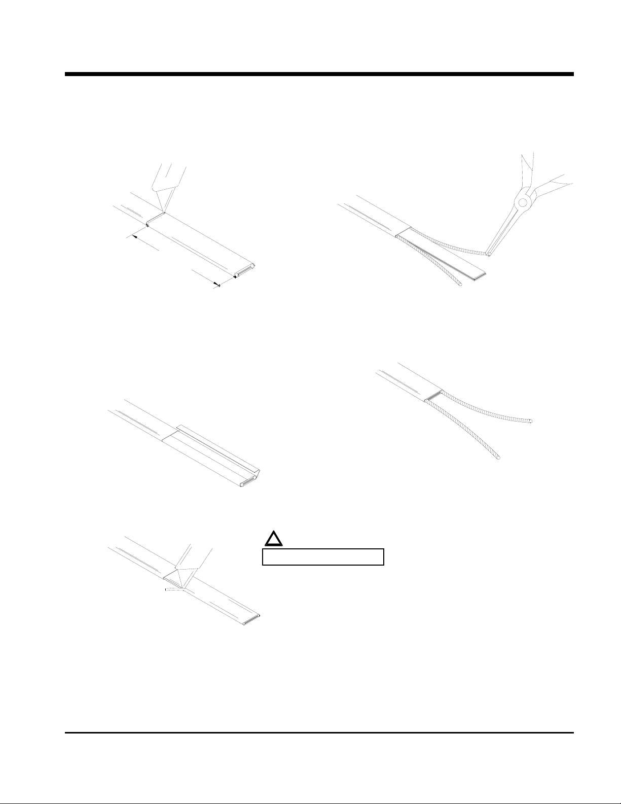
FOR ALL NELSON LT, CLT & HLT PRODUCTS
(See sheet 6 for an alternate method of HLT products.)
102mm (4")
1) Lightly
2) Lightly cut the outer jacket up the center
3) Remove the jacket from the heater cable.
cut around heater outer jacket
102mm (4") from the end. Bend cable to
break outer jacket.
between the first cut mark & the cable end.
Bend cable to break outer jacket.
!
WARNING:
DO NOT CUT BUS WIRES.
5) Starting at the end, pull each bus wire away
from the core material.
6) Remove exposed core material.
7) Cut 6mm (0.25") off the end of each bus
wire.
8) Proceed to “Power Termination”, sheet 7.
4) Shave the core material from the outside of
each bus wire.
P.O. BOX 726 TULSA, OK 74101 TEL 918-627-5530 FAX 918-641-7336 www.nelsonheaters.com
GA-1893 Rev. 6
Sheet 5 of 8
January 2010
Page 46
NELSON™ HEAT TRACING SYSTEMS
INSTALLATION
ALT-LPM POWER CONNECTION KIT WITHOUT ENCLOSURE INSTRUCTIONS
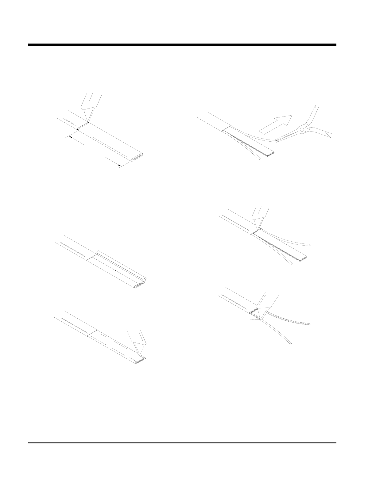
HLT PRODUCTS
ALTERNATE METHOD
102mm (4")
1) Lightly
2) Lightly cut the outer jacket up the center
cut around heater outer jacket
102mm (4") from the end. Bend cable to
break outer jacket.
between the first cut mark & the cable end.
Bend cable to break outer jacket.
5) Starting at the end, in the same plane as the
cable, pull each bus wire away from the core
material.
3) Remove the jacket from the heater cable.
4) Make a cut inside each bus wire.
6) Remove exposed core material.
7) Remove the remaining core material off the
outside of each bus wire.
8) Cut 6mm (0.25") off the end of each bus
wire.
9) Proceed to “Power Termination”, sheet 7.
P.O. BOX 726 TULSA, OK 74101 TEL 918-627-5530 FAX 918-641-7336 www.nelsonheaters.com
GA-1893 Rev. 6
Sheet 6 of 8
January 2010
Page 47
NELSON™ HEAT TRACING SYSTEMS
INSTALLATION
ALT-LPM POWER CONNECTION KIT WITHOUT ENCLOSURE INSTRUCTIONS
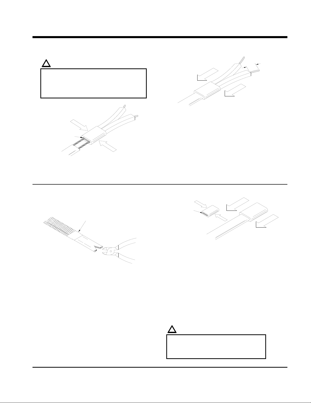
POWER TERMINATION
!
WARNINGS:
Bus wires must not touch or cross while
inserting into power termination / end seal.
Only power terminations / end seals
specifically approved for the vendor’s style
and type of heater cable must be used.
pply silicone here
1) Insert bus wires into power termination.
2) Squeeze power termination opening and fill
with silicone.
END SEAL
Fiberglass Tape
(not included in kit)
13mm (0.5")
3) Push power termination to overlap jacket.
4) At this point, if you’re installing the end seal,
see the “End Seal” section below. Otherwise,
proceed to “Power Connection”, sheet 8.
apply silicone here
3) Squeeze the end seal and fill with silicone.
4) Push end seal over the heater cable.
1) For Braided Products:
Cut braid back 25mm (1") & tape in place
with fiberglass tape.
For Overjacket Products:
Remove 13mm (0.5") of overjacket exposing
the braid, then remove the 13mm (0.5”) of
For Overjacket Products:
The end seal should overlap the overjacket.
5) The silicone will set up in about 30 minutes
with a complete cure after 24 hours.
6) Proceed to “Power Connection”, sheet 8.
exposed braid.
2) Make a 10mm (0.4”) cut at the end of the
heater cable.
P.O. BOX 726 TULSA, OK 74101 TEL 918-627-5530 FAX 918-641-7336 www.nelsonheaters.com
!
WARNINGS:
Do not megger or hi-pot until silicone is
completely cured.
Braid must be kept away from bus wi res
or shorting will occur.
GA-1893 Rev. 6
Sheet 7 of 8
January 2010
Page 48
NELSON™ HEAT TRACING SYSTEMS
INSTALLATION
ALT-LPM POWER CONNECTION KIT WITHOUT ENCLOSURE INSTRUCTIONS
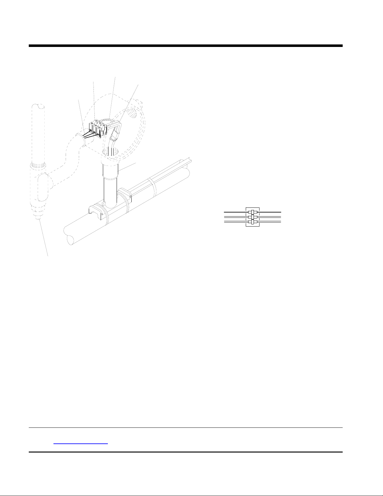
POWER CONNECTION
Terminal Block
Ground Wire
Braid
Power Termination
Box Adapter
TERMINAL BLOCK CONNECTION
Ground
Power Leads
*Conduit & Drain
(must be positioned lower than the junction box)
Braid
Heater Cable
Note: This detail shows internal grounding of braid.
1. Place gasket on box adapter.
2. Secure junction box onto box adapter until tightly fitted. DO NOT OVER TIGHTEN.
3. Connect the power wiring and heater cable to terminal block.
4. Ground Connection:
For External Ground Connected Heaters:
Connect ground braid to stand-off using the ground screw. See diagram on sheet 1.
For Internal Ground Connected Heaters:
Connect ground wire to terminal block inside junction box using the ground screw.
See diagram on sheet 1.
Connect ground wire and braid to terminal block. See diagram above.
5. For Overjacket J or JT Products only:
Apply silicone at point braid leaves the overjacket.
6. Push all wires and heater cable inside junction box.
7. Install box cover gasket and box cover onto junction box.
Nelson Heat Tracing Systems products are supplied with a limited warranty. Complete Terms and Conditions may be found on Nelson's
website at www.nelsonheaters.com
.
P.O. BOX 726 TULSA, OK 74101 TEL 918-627-5530 FAX 918-641-7336 www.nelsonheaters.com
GA-1893 Rev. 6
Sheet 8 of 8
January 2010
 Loading...