

Nedap N V IQ User Manual


© 2003 Nedap Retail Support Netherlands
Parallelweg 2d, 7141 DC Groenlo
The software / hardware described in this book / file is furnished under a license agreement and may be used only in accordance with the
terms of the agreement.
Documentation version 1.0
Copyright Notice
All Rights Reserved.
Any technical documentation that is made available by Nedap Retail Support is the
copyrighted work of Nedap Retail Support and is owned by Nedap Retail Support.
NO WARRANTY. The technical documentation is being delivered to you AS-IS and
Nedap Retail Support makes no warranty as to its accuracy or use. Any use of the
technical documentation or the information contained therein is at the risk of the user.
Documentation may include technical or other inaccuracies or typographical errors.
Nedap Retail Support the right to make changes without prior notice.
No part of this publication may be copied without the express written permission of
Nedap Retail Support, Parallelweg 2d, 7141 DC Groenlo, Netherlands
Trademarks
Nedap, the Nedap logo, Nedap EASi/Net and the Nedap EASi/Net are registered trademarks of Nedap N.V. Groenlo.
Other product names mentioned in this manual may be trademarks or registered
trademarks of their respective companies and are hereby acknowledged.
Printed in the Netherlands
OS/T Course 2003 © NEDAP Retail Support 2003
2

Technical Support:
- E-mail:support-rs@nedap.nl
- H. Hammer
+31 (0) 544 47 15 19
h.hammer@nedap.nl
- H. Broekhuis
+31 (0) 544 47 15 02
h.broekhuis@nedap.nl
- Fax:
+31 (0) 544 46 58 14
Visitor’s address:
Nedap Retail Support
Parallelweg 2d
Groenlo
Netherlands
Postal address:
Nedap Retail Support
Postbus 102
7140 AC Groenlo
Netherlands
OS/T Course 2003 © NEDAP Retail Support 2003
3

Table of contents
Technical Support: .................................................................................................................................... 3
BQ PCB ............................................................................................................................................. 5
EQ PCB ............................................................................................................................................. 7
EQ3E PCB......................................................................................................................................... 9
IQ PCB............................................................................................................................................. 11
IQ3E PCB ........................................................................................................................................ 13
Attenuation....................................................................................................................................... 15
IO Connector K23 ............................................................................................................................ 16
IO Connector K24 ............................................................................................................................ 16
System configurations ..................................................................................................................... 17
BQ System , 1 aisle, Deactivatorunit ............................................................................................... 18
EQ System , 3 aisles ....................................................................................................................... 19
IQ System , 7 aisles, MD CC........................................................................................................... 21
Checklist modem settings iNCC ...................................................................................................... 20
Connecting a PC to a XQ or EQ/IQ Unit ......................................................................................... 28
Connecting a XQ or EQ/IQ unit to a modem ................................................................................... 29
Connecting to an ISDN line using the DeTeWe TA33 terminal adapter ......................................... 30
OS/T Course 2003 © NEDAP Retail Support 2003
4
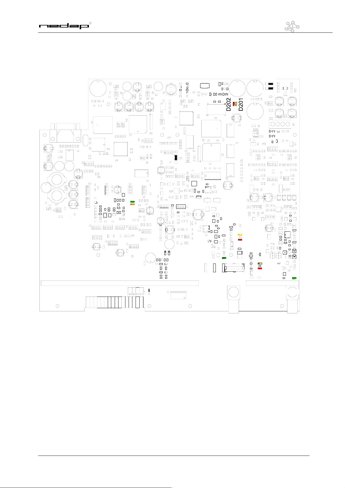
BQ PCB
K203
K205 K201
K16
K19
D25
D26
K202
K204
K3
P3
K23
K24
K11
K5
D19
D16
D301
D300
D311
K300
OS/T Course 2003 © NEDAP Retail Support 2003
5

The following points can be used:
K3 Oscilloscope Tx K201 Handheld terminal RxTx
K5 Output Tx (connector 3) K202 Oscilloscope Rx
K9 Jumper Attenuation K203 Jumper
K11 Power Input K204 Jumper
K12 Jumper Attenuation K205 Handheld terminal NCC
K13 Jumper Attenuation K300 Output Rx (connector 1)
K15 Jumper Attenuation P1 PA Drive Adjustment
K16 RS232 Interface Connector P2 Phase Adjustment Tx
K21 Connector FCI P3 Mixer Bias Adjustment
K23 IO Connector P4 Slave Data communication Rx
K24 IO Connector P5 Master Data communication Rx
Indicator leds:
D11 Mux Connector 1 TX D48 Customer Counting: Led on = active
D12 Mux Connector 2 TX D202 Communication Error RxTx
D16 Lamp On Connector 3 D220 Label Detection Alarm NCC on = detection
D19 Lamp Overload Connector 3 D221 Communication Error NCC
D25 Sweep Lock D300 Lamp Overload Connector 1
D26 Center Lock D301 Lamp On Connector 1
D201 Label Alarm RxTx D311 Mux Connector 1 RX
D47 Customer Counting: Led on = active D202 Communication Error RxTx
OS/T Course 2003 © NEDAP Retail Support 2003
6
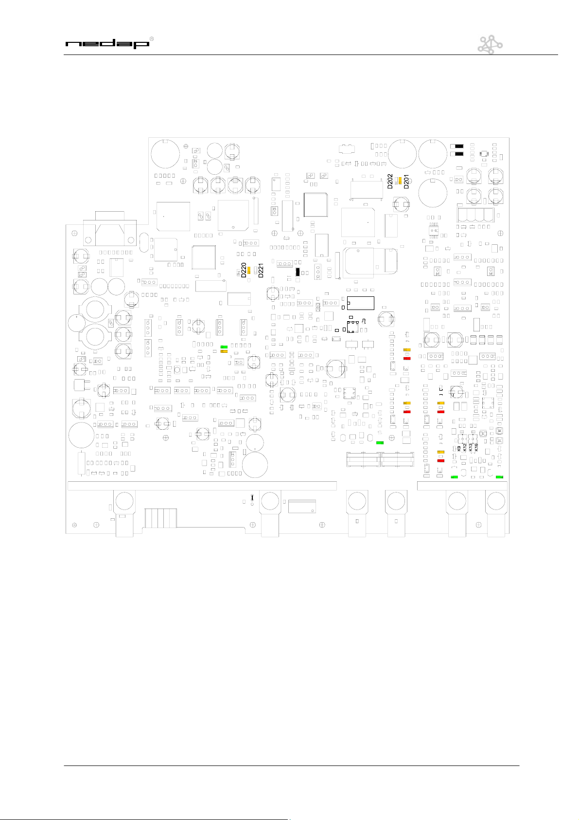
EQ PCB
P1
K21
K201 K202
D18
D17
K205
K16
K19
P2
D25
D26
K203
K204
K3
P3
P4
P5
K6
K23
15
K10
K4
D19
D16
D11
K5
D303
D302
D301
D300
K301
D311D312
K300
7
OS/T Course 2003 © NEDAP Retail Support 2003
The following points can be used:
K3 Oscilloscope Tx K201 Handheld terminal RxTx
K4 Output Tx (connector 4) K202 Oscilloscope Rx
K5 Output Tx (connector 3) K203 Jumper
K6 Synchronization In K204 Jumper
K9 Jumper Attenuation K205 Handheld terminal NCC
K10 Master connector K300 Output Rx (connector 1)
K11 Power Input K301 Output Rx (connector 2)
K12 Jumper Attenuation P1 PA Drive Adjustment
K13 Jumper Attenuation P2 Phase Adjustment Tx
K15 Jumper Attenuation P3 Mixer Bias Adjustment
K16 RS232 Interface Connector P4 Slave Data communication Rx
K21 Connector FCI P5 Master Data communication Rx
K23 IO Connector
Indicator leds:
D11 Mux Connector 1 TX D202 Communication Error RxTx
D12 Mux Connector 2 TX D220 Label Detection Alarm NCC on = detection
D16 Lamp On Connector 3 D221 Communication Error NCC
D17 Lamp On Connector 4 D300 Lamp Overload Connector 1
D18 Lamp Overload Connector 4 D301 Lamp On Connector 1
D19 Lamp Overload Connector 3 D302 Lamp Overload Connector 2
D25 Sweep Lock D303 Lamp On Connector 2
D26 Center Lock D311 Mux Connector 1 RX
D201 Label Alarm RxTx D312 Mux Connector 2 RX
OS/T Course 2003 © NEDAP Retail Support 2003
8
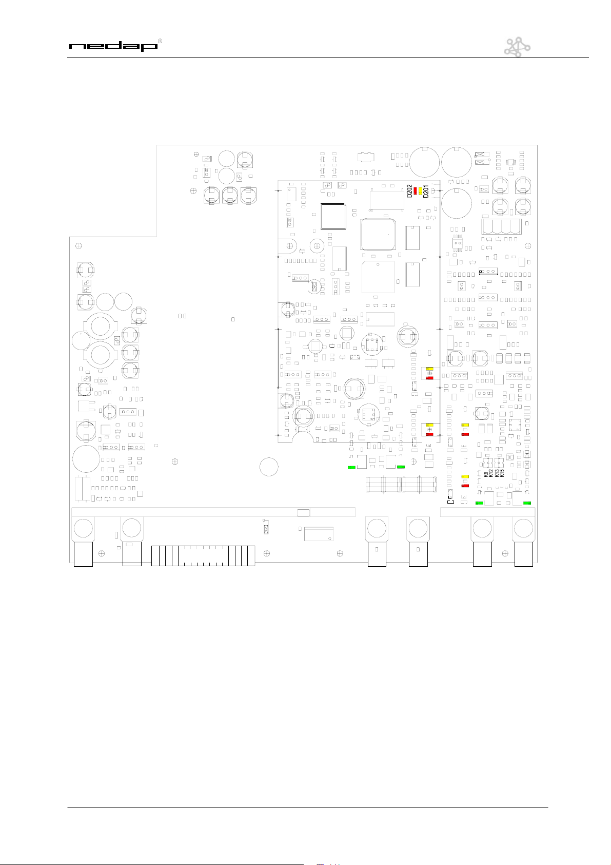
EQ3E PCB
K
P1
P2
K201 K202
K203
K204
K3
D18
D312
K301
P3
D11D11D11D11D11
D311
K300
D17
P4
D12
K6
K7
1
K23
16
K11
K4
D19
D16
D11
K5
D303
D302
D301
D300
9
OS/T Course 2003 © NEDAP Retail Support 2003
The following points can be used:
K3 Oscilloscope Tx K24 IO Connector
K4 Output Tx (connector 4) K201 Handheld terminal RxTx
K5 Output Tx (connector 3) K202 Oscilloscope Rx
K6 Synchronization In K203 Jumper
K7 Synchronization In K204 Jumper
K9 Jumper Attenuation K300 Output Rx (connector 1)
K11 Power Input K301 Output Rx (connector 2)
K12 Jumper Attenuation P1 PA Drive Adjustment
K13 Jumper Attenuation P2 Phase Adjustment Tx
K15 Jumper Attenuation P3 Mixer Bias Adjustment
K21 Connector FCI
Indicator leds:
D11 Mux Connector 1 TX D202 Communication Error RxTx
D12 Mux Connector 2 TX D300 Lamp Overload Connector 1
D16 Lamp On Connector 3 D301 Lamp On Connector 1
D17 Lamp On Connector 4 D302 Lamp Overload Connector 2
D18 Lamp Overload Connector 4 D303 Lamp On Connector 2
D19 Lamp Overload Connector 3 D311 Mux Connector 1 RX
D201 Label Alarm RxTx D312 Mux Connector 2 RX
OS/T Course 2003 © NEDAP Retail Support 2003
10
 Loading...