

Page 1
NW Global Vending – TECHNICAL MANUAL
This document was produced by MARK AC for the exclusive use of the technical personnel in the after-sales service.
. No part of this document may be divulged to a third party or reproduced partially or entirely without the prior permission of NW GLOBAL VENDING
. All rights reserved.
New dispenser “KORO” 07/10/2005 page 1 / 42
SERVICE MANUAL
New Dispenser
“Koro”
A
A
A
F
F
F
T
T
T
E
E
E
R
R
R
-
-
-
S
S
S
A
A
A
L
L
L
E
E
E
S
S
S
S
S
S
E
E
E
R
R
R
V
V
V
I
I
I
C
C
C
E
E
E
Page 2

NW Global Vending – TECHNICAL MANUAL
This document was produced by MARK AC for the exclusive use of the technical personnel in the after-sales service.
. No part of this document may be divulged to a third party or reproduced partially or entirely without the prior permission of NW GLOBAL VENDING
. All rights reserved.
New dispenser “KORO” 07/10/2005 page 2 / 42
TABLE OF CONTENTS
1
2
2.1
2.2
3
4
5
6
7
8
9
10
11
12
13
14
15
16
17
18
19
20
21
22
23
24
25
26
27
28
29
30
31
32
PLANNED MODELS
MAIN EXTERNAL COMPONENTS
MAIN INTERNAL COMPONENTS
REAR COMPARTMENT WITHOUT PROTECTIVE CASING
LIST OF MAIN COMPONENTS
TECHNICAL DATA AND FEATURES
ELECTRICAL SAFETY AND RELEVANT STANDARDS
REQUIREMENT FOR THE USERS
HYDRAULIC LAYOUT OF ESPRESSO VERSION
HYDRAULIC LAYOUT OF INSTANT VERSION
HYDRAULIC LAYOUT OF FRESH BREWER VERSION
HYDRAULIC LAYOUT OF VARIABLE CHAMBER ESPRESSO
INTERNAL LAYOUTS
ELECTRICAL SYSTEMS – CONNECTIONS
CONNECTION OF ELECTRONIC BOARDS
WIRING DIAGRAMS
ACTUATION BOARD – CONFIGURATIONS
SIGMA BREWER CONTROL BOARD
PUSH-BUTTON BOARD
BOILER CONTROL BOARD
AIR-BREAK AND BOILERS (INSTANT & ESPRESSO)
PUMPS AND BYPASS
ESPRESSO COFFEE, FRESH-BREWER UNIT & SIGMA
BREWER
SPOUTS ASSEMBLY
POWDER PRODUCT CONTAINER AND DOSER DEVICES
ASSY.
MIXER UNIT
COFFEE GRINDER AND DOSER DEVICE ASSEMBLY
POWDER AND LIQUID DOSE TABLES
ROUTINE AND EXTRAORDINARY MAINTENANCE
PROGRAM
TROUBLE-SHOOTING
HACCP DIRECTIVE
DAILY CLEANING AND HYGIENE PROGRAM
DAILY CLEANING AND HYGIENE PROGRAM FRESHBREWER UNIT
MONTHLY CLEANING AND HYGIENE PROGRAM
Pag. 3 - 4
Pag. 5
Pag. 6
Pag. 7-8
Pag. 9
Pag. 10
Pag. 11
Pag. 11
Pag. 12
Pag. 13
Pag. 14
Pag. 15
Pag. 16
Pag. 17
Pag. 17- 18
Pag. 19
Pag. 20-21
Pag. 22
Pag. 23
Pag. 23
Pag. 24 - 26
Pag. 27
Pag. 28 -29
Pag. 30
Pag. 31
Pag. 32
Pag. 33
Pag. 34
Pag. 35
Pag. 36 - 38
Pag. 39
Pag. 40
Pag. 41
Pag. 42
Page 3

NW Global Vending – TECHNICAL MANUAL
This document was produced by MARK AC for the exclusive use of the technical personnel in the after-sales service.
. No part of this document may be divulged to a third party or reproduced partially or entirely without the prior permission of NW GLOBAL VENDING
. All rights reserved.
New dispenser “KORO” 07/10/2005 page 3 / 42
I
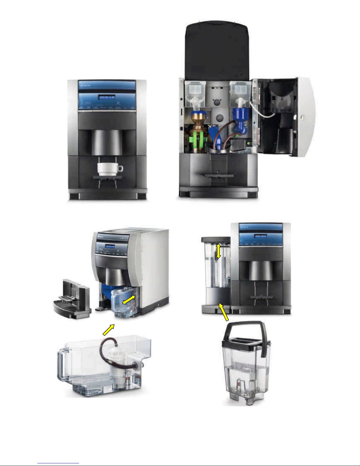
NSTANT VERSION (OPEN AND CLOSED DOOR)
E
SPRESSO VERSION (OPEN AND CLOSED DOOR)
1 -
PLANNED MODELS
Page 4
NW Global Vending – TECHNICAL MANUAL
This document was produced by MARK AC for the exclusive use of the technical personnel in the after-sales service.
. No part of this document may be divulged to a third party or reproduced partially or entirely without the prior permission of NW GLOBAL VENDING
. All rights reserved.
New dispenser “KORO” 07/10/2005 page 4 / 42
External water supply tank
Internal water supply tank
FRESH-BREWER VERSION (OPEN AND CLOSED DOOR)
Page 5
NW Global Vending – TECHNICAL MANUAL
This document was produced by MARK AC for the exclusive use of the technical personnel in the after-sales service.
. No part of this document may be divulged to a third party or reproduced partially or entirely without the prior permission of NW GLOBAL VENDING
. All rights reserved.
New dispenser “KORO” 07/10/2005 page 5 / 42
3 4 6 5 1 2 7 8 9 10 11
2 -
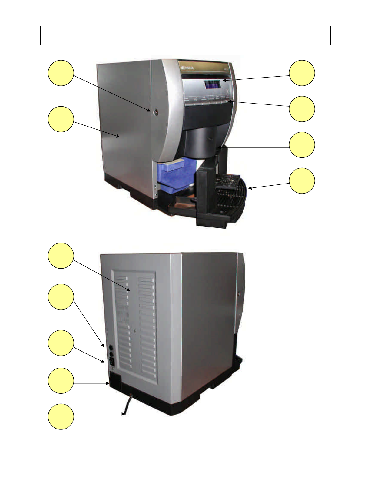
MAIN EXTERNAL COMPONENTS
Page 6

NW Global Vending – TECHNICAL MANUAL
This document was produced by MARK AC for the exclusive use of the technical personnel in the after-sales service.
. No part of this document may be divulged to a third party or reproduced partially or entirely without the prior permission of NW GLOBAL VENDING
. All rights reserved.
New dispenser “KORO” 07/10/2005 page 6 / 42
1 6 2 8 4
Fustino
fondi liquidi
Mixer
Ugelli mobili
Contenitori
solubili
2
.1
- MAIN INTE
RNAL COMPONENTS
13 14 17 16 15 12 18 19 20 21 22
Espresso
Version
26 27 28 29
23 24 25
Fresh
Brewer
Version
Page 7
NW Global Vending – TECHNICAL MANUAL
This document was produced by MARK AC for the exclusive use of the technical personnel in the after-sales service.
. No part of this document may be divulged to a third party or reproduced partially or entirely without the prior permission of NW GLOBAL VENDING
. All rights reserved.
New dispenser “KORO” 07/10/2005 page 7 / 42
VISTA
CON PORTA APERTA
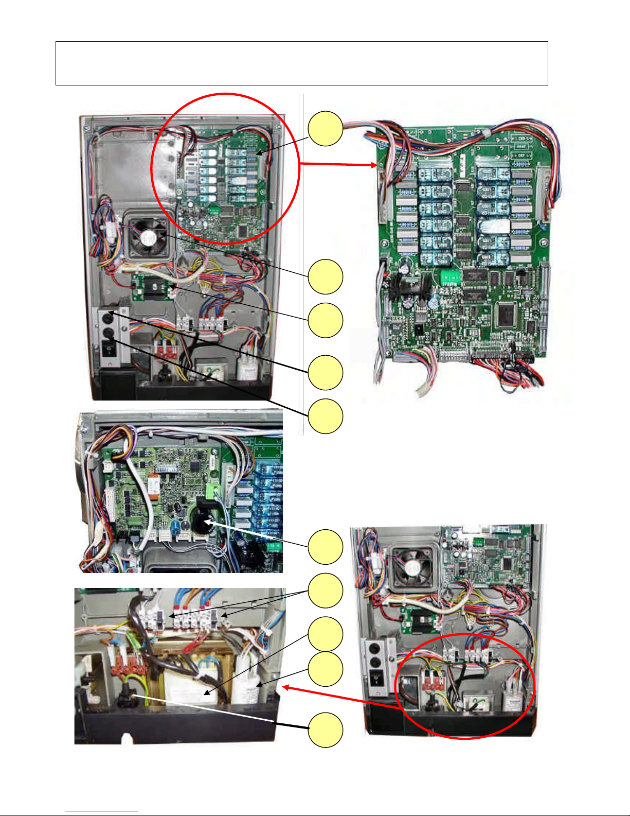
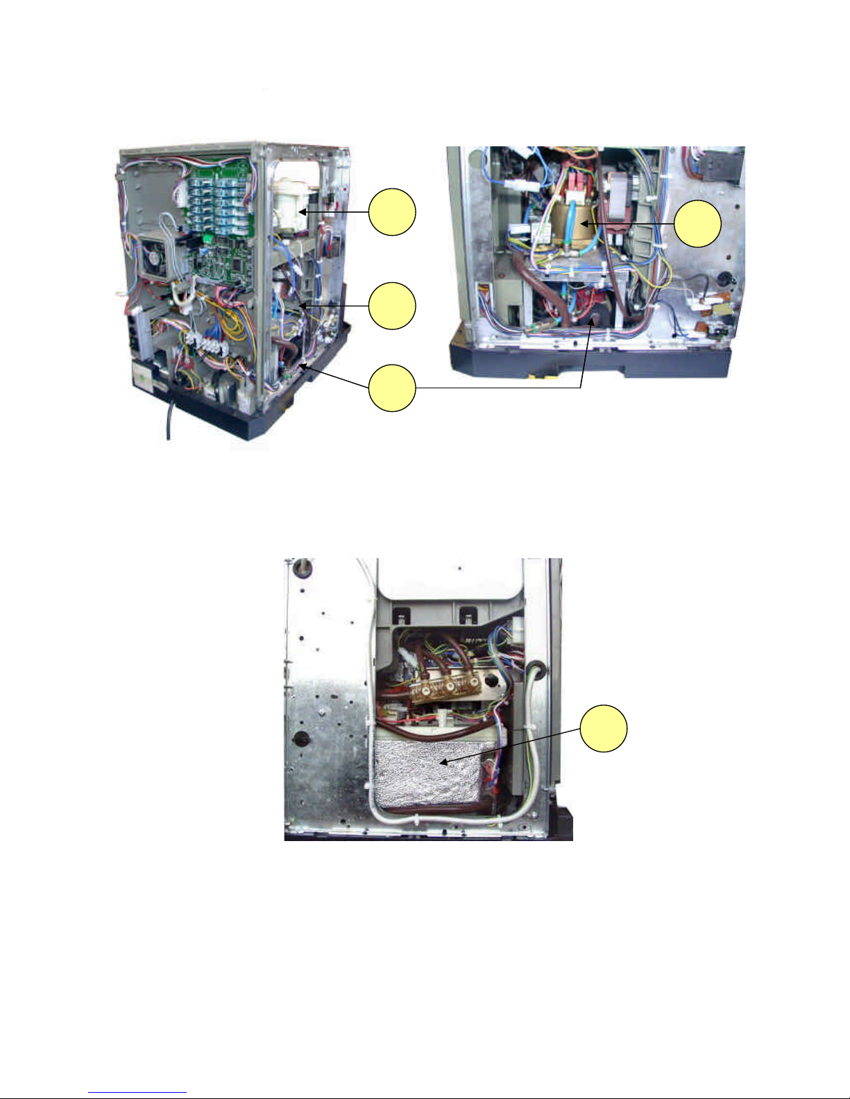
2.2 REAR COMPARTMENT WITHOUT PROTECTIVE
CASING
Detail of CPU / actuation machine board
Detail of machine board
(FRESH-BREWER version only)
30 31 32 36 35 37 39 33 34 38
Page 8
NW Global Vending – TECHNICAL MANUAL
This document was produced by MARK AC for the exclusive use of the technical personnel in the after-sales service.
. No part of this document may be divulged to a third party or reproduced partially or entirely without the prior permission of NW GLOBAL VENDING
. All rights reserved.
New dispenser “KORO” 07/10/2005 page 8 / 42
Perspective view without protective casing
Side view without protective casing
– espresso boiler side
Side view without protective casing
open-top boiler side (FB – Instant)
42 40 44 41 43
Page 9

NW Global Vending – TECHNICAL MANUAL
This document was produced by MARK AC for the exclusive use of the technical personnel in the after-sales service.
. No part of this document may be divulged to a third party or reproduced partially or entirely without the prior permission of NW GLOBAL VENDING
. All rights reserved.
New dispenser “KORO” 07/10/2005 page 9 / 42
3 - LIST OF MAIN COMPONENTS
N° Ref.
DESCRIPTION
1 Lock
2 Cabinet
3 User interface
4 Selection keypad
5 Dispensing unit
6 Dispensing compartment
7 Back protective casing
8 Grid fuses
9 Main switch
10 Water inlet solenoid valve
11 Power supply cable
12 Grinder / doser device
13 Instant product container
14 Mixers
15 Door
16 Coffee beans door
17 Coffee beans hopper
18 Decaf coffee door (powder)
19 Water supply tank (espresso)
20 Drip tray
21 Solid waste container
22 Brewer unit Z3000
23 Coffee container for FB (powder)
24 Instant product container
25 Dispensing compartment
26 Hot water nozzle
27 FB unit SIGMA BREWER
28 Mixers
29 Protective casing
30 Actuation board
31 Steam exhauster
32 Boiler heating element actuation board
33 Grid fuses
34 Main switch
35 Sigma Brewer control board (FB version only)
36 Transformer fuses
37 Transformer
38 Grid noise suppressor
39 Power supply cable clamp
40 Coffee grinder unit
41 Espresso boiler compartment
42 Espresso boiler
43 Electromagnetic pump
44 Open-top boiler (Instant & Fresh brewer)
Page 10
NW Global Vending – TECHNICAL MANUAL
This document was produced by MARK AC for the exclusive use of the technical personnel in the after-sales service.
. No part of this document may be divulged to a third party or reproduced partially or entirely without the prior permission of NW GLOBAL VENDING
. All rights reserved.
New dispenser “KORO” 07/10/2005 page 10 / 42
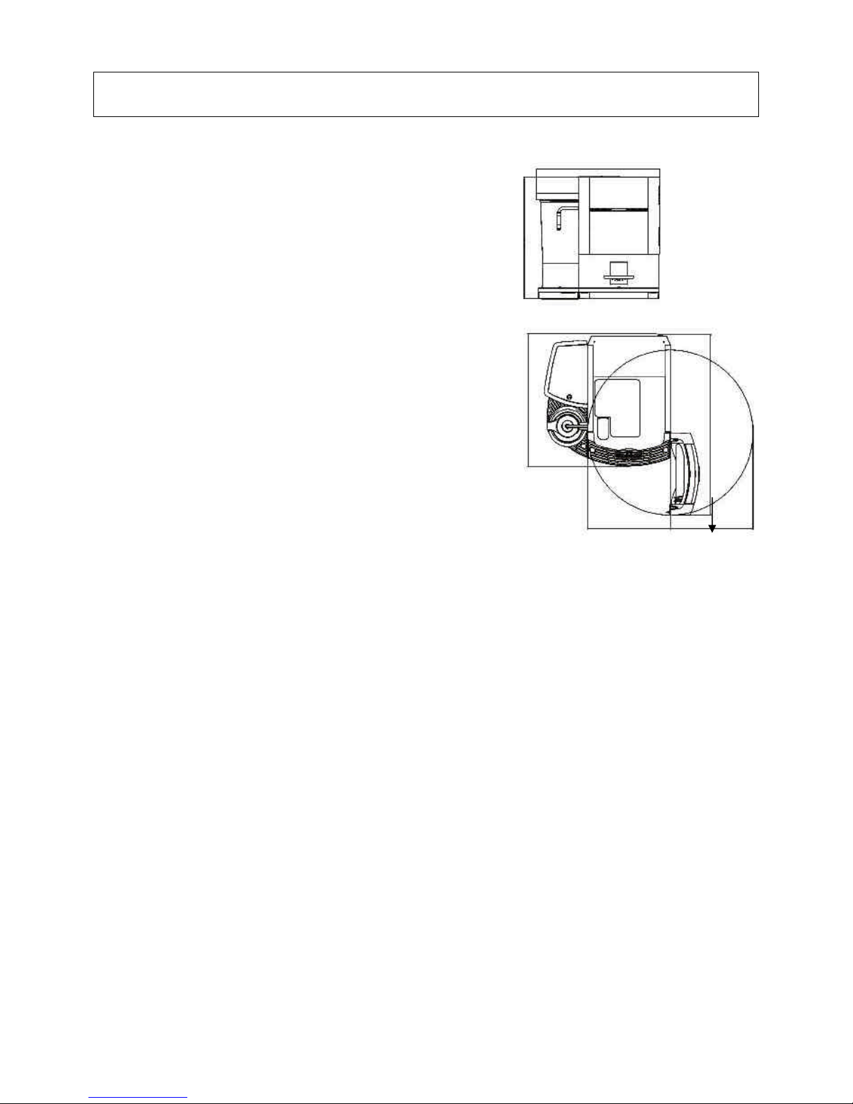
4 – TECHNICAL DATA AND FEATURES
Height 500 mm
Width 508 mm
Depth 528 mm
Overall depth with door open 724 mm
Weight 28 Kg
Power supply voltage 230 V AC - 50 Hz
Installed power 1500 W (espresso)
2400 W (FB / I)
Payment systems used
The machine is pre-set to use
(by means of specific kits) payment systems
coin mechanisms and 24 V DC validators with protocols
EXECUTIVE BDV, MDB
Water supply:
From the mains with a water pressure of 5 to 85 N/cm2
BASE VERSIONS:
Espresso – Instant – Fresh brewer
INSTALLED BOILERS AND TEMPERATURE
One pressure boiler for the espresso version
One open-top boiler for instant and Fresh-brew
versions
Temperature setting via software
SAFETY DEVICES
Main switch (at the back) – Main switch upon opening the door
Water inlet solenoid valve with overflow device
Manual-reset boiler safety thermostat
Manual-reset instant boiler anti-boiling thermostat
Air-break float block
Presence of liquid waste tray – Presence of coffee grounds tray
Boiler sensor control (short-circuit or failure)
Double heating and timing protection for:
Pump – Doser devices – Coffee unit ratiomotor – Coffee grinder – Mixer motors
Fuse protection for: Transformers, electronic boards and main wiring
CONTROLS
Presence of water
Presence of coffee
Operating temperature reached
508 500 528 331 724 331
Page 11
NW Global Vending – TECHNICAL MANUAL
This document was produced by MARK AC for the exclusive use of the technical personnel in the after-sales service.
. No part of this document may be divulged to a third party or reproduced partially or entirely without the prior permission of NW GLOBAL VENDING
. All rights reserved.
New dispenser “KORO” 07/10/2005 page 11 / 42
5 - ELECTRICAL SAFETY AND RELEVANT STANDARDS
The vending machine New Dispenser was designed and made in conformity with the
provisions of the following directives and related European standards:
MACHINE SAFETY DIRECTIVE EEC 98/37
EN 60529 UNI EN 292 –1-2 IEC 695-2-2
LOW VOLTAGE DIRECTIVE EEC 73/23; EEC 89/392; EEC
89/336
(the low voltage directive covers all equipment powered with voltage below 400 V AC)
The following European standards are applied:
EN 60335-2-14 EN 60335-2-15 EN 60335-2-24 EN 60335-2-75
ELECTROMAGNETIC COMPATIBILITY DIRECTIVE
EN 61000-3-3 EN 61000-4-2 EN 61000-4-3 EN 61000-4-4 EN 61000-4-5 EN 61000-4-11
---…----…---…---
With regard to Low Voltage and Electromagnetic Compatibility this vending machine was tested and
certified by a certifying body authorised by ministerial decree: IMQ.
It is therefore prohibited (on pain of voiding the warranty and the responsibility of the certification) to
replace any electrical component with non-original parts during the routine and extraordinary maintenance
operations.
Therefore it is also prohibited to:
Tamper with or deactivate the safety systems installed in the vending machine.
Install the vending machine outdoor or in any case in a place that is not protected from the weather.
Use the vending machine for purposes other than those indicated in the sales contract.
Connect the vending machine by means of extension cords or multiple sockets and/or adapters.
Use water jets for cleaning.
Then, it is also compulsory to:
Verify the conformity and suitability of power supply line and of the power outlet.
6 – REQUIREMENT FOR THE USERS
For safety purposes, three different operators with different qualifications have been defined.
USER
The user is practically the final user who buys the products from the machine.
The user must not have any access whatsoever to the inside of the machine.
PERSON RESPONSIBLE FOR REFILLING AND ROUTINE CLEANING
The person responsible for refilling has the key for opening the machine and is in charge of the refilling,
cleaning and internal hygiene of the machine.
He must not have any access to energised parts or moving parts.
MAINTENANCE TECHNICIAN
The maintenance technician must be a highly skilled person and must be aware of the electrical hazards in
the event of complex technical operations and can operate with the machine switched on and the door
open, using the safety key supplied.
Page 12

NW Global Vending – TECHNICAL MANUAL
This document was produced by MARK AC for the exclusive use of the technical personnel in the after-sales service.
. No part of this document may be divulged to a third party or reproduced partially or entirely without the prior permission of NW GLOBAL VENDING
. All rights reserved.
New dispenser “KORO” 07/10/2005 page 12 / 42
7 – HYDRAULIC LAYOUT “ESPRESSO”
ESPRESSO VERSION COMPONENTS
N.B. The diagram shown is given only as a reference as it may differ for each version.
REF. DESCRIPTION REF. DESCRIPTION REF. DESCRIPTION
1
Spouts assembly 2 Pump 3 Mixers
4
Boiler assembly 5 Brewer unit 6 Solenoid valve block
7
Bypass 8 Water supply tank 9 Volumetric counter
3 5 1 2 4 6
8 9 7
Page 13

NW Global Vending – TECHNICAL MANUAL
This document was produced by MARK AC for the exclusive use of the technical personnel in the after-sales service.
. No part of this document may be divulged to a third party or reproduced partially or entirely without the prior permission of NW GLOBAL VENDING
. All rights reserved.
New dispenser “KORO” 07/10/2005 page 13 / 42
INSTANT VERSION COMPONENTS
N.B. The diagram shown is given only as a reference as it may differ for each version.
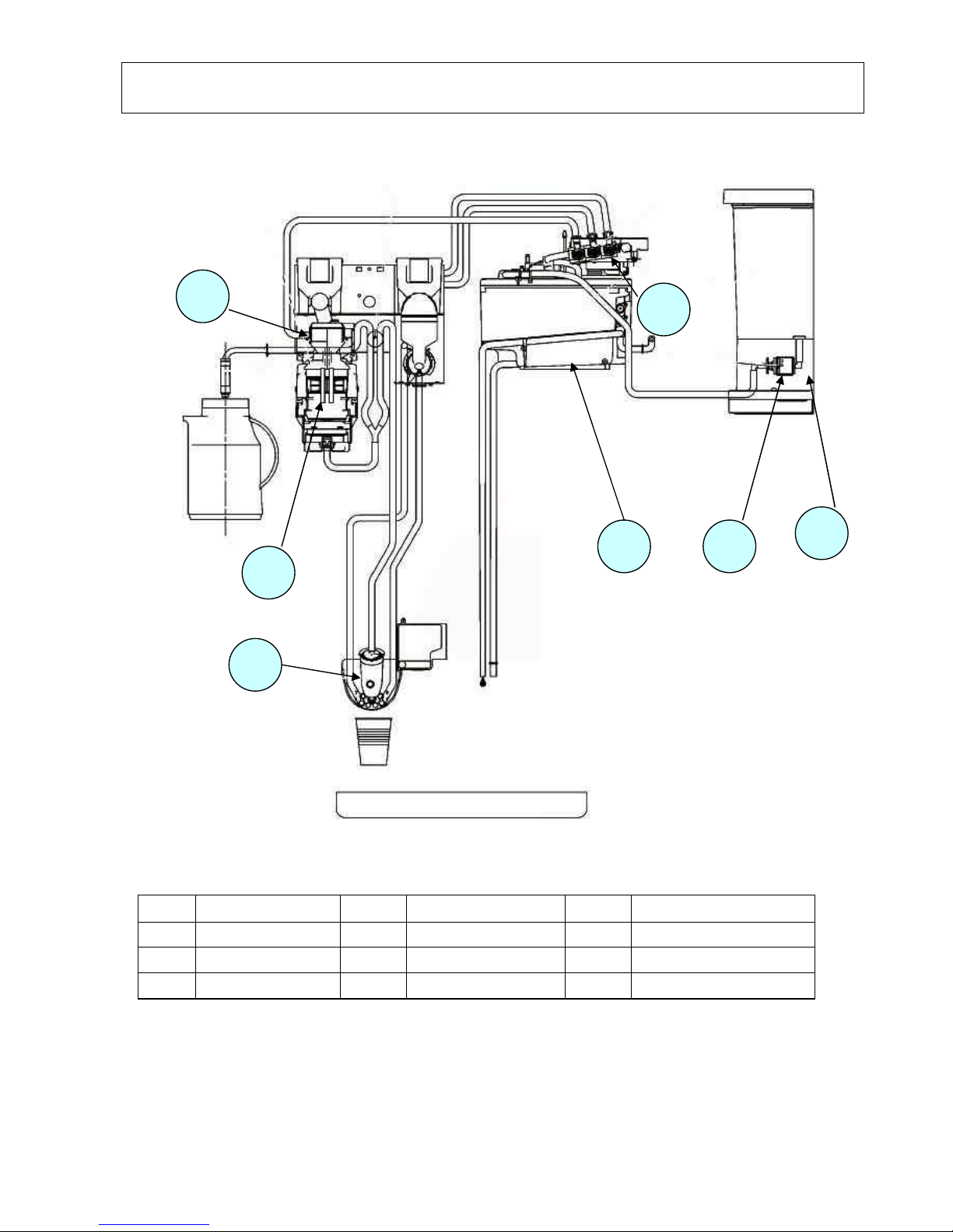
8 – HYDRAULIC LAYOUT INSTANT
REF. DESCRIPTION REF. DESCRIPTION REF. DESCRIPTION
1
Spouts assembly 2 Mixers 3 Solenoid valves
4
Boiler assembly 5 Water supply pump 6 Water supply tank
2 1 6 5 4 3
Page 14
NW Global Vending – TECHNICAL MANUAL
This document was produced by MARK AC for the exclusive use of the technical personnel in the after-sales service.
. No part of this document may be divulged to a third party or reproduced partially or entirely without the prior permission of NW GLOBAL VENDING
. All rights reserved.
New dispenser “KORO” 07/10/2005 page 14 / 42
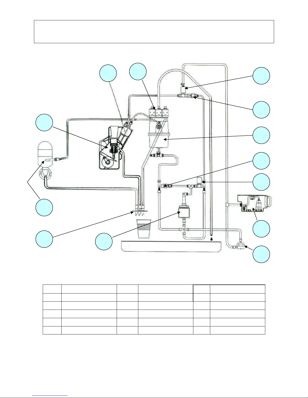
9 – HYDRAULIC LAYOUT “FRESH BREWER”
COMPONENTI VERSIONE FRESH BREWER
N.B. The diagram shown is given only as a reference as it may differ for each version.
REF. DESCRIPTION REF. DESCRIPTION REF. DESCRIPTION
1
Spouts assembly 2 Sigma Brewer boiler 3 Mixer
4
Solenoid valves 5 Boiler 6 Water supply pump
7
Water supply tank 8 9
7 6 5 4 1 2 3
Page 15
NW Global Vending – TECHNICAL MANUAL
This document was produced by MARK AC for the exclusive use of the technical personnel in the after-sales service.
. No part of this document may be divulged to a third party or reproduced partially or entirely without the prior permission of NW GLOBAL VENDING
. All rights reserved.
New dispenser “KORO” 07/10/2005 page 15 / 42
10 – HYDRAULIC LAYOUT
“VARIABLE CHAMBER ESPRESSO ”
COMPONENTS OF ESPRESSO VERSION WITH VARIABLE BREWING CHAMBER
This diagram is used exclusively for variable chamber brewer units, as it differs also with regard to the electrical circuit
and it is specific to some versions
REF. DESCRIPTION REF. DESCRIPTION REF. DESCRIPTION
1
Spouts assembly 2 Mixer unit 3 Brewer unit
4
Chamber with piston 5 Solenoid valve assembly 6 Discharge solenoid valve
7
By-pass (4 bar) 8 Boiler 9 By-pass (12 bar)
10
Piston solenoid valve 11 Water supply tank 12 Volumetric counter
13
Vibration pump
4 8 9 2 1 5 6 7 3
10 11 12 13
Page 16
NW Global Vending – TECHNICAL MANUAL
This document was produced by MARK AC for the exclusive use of the technical personnel in the after-sales service.
. No part of this document may be divulged to a third party or reproduced partially or entirely without the prior permission of NW GLOBAL VENDING
. All rights reserved.
New dispenser “KORO” 07/10/2005 page 16 / 42
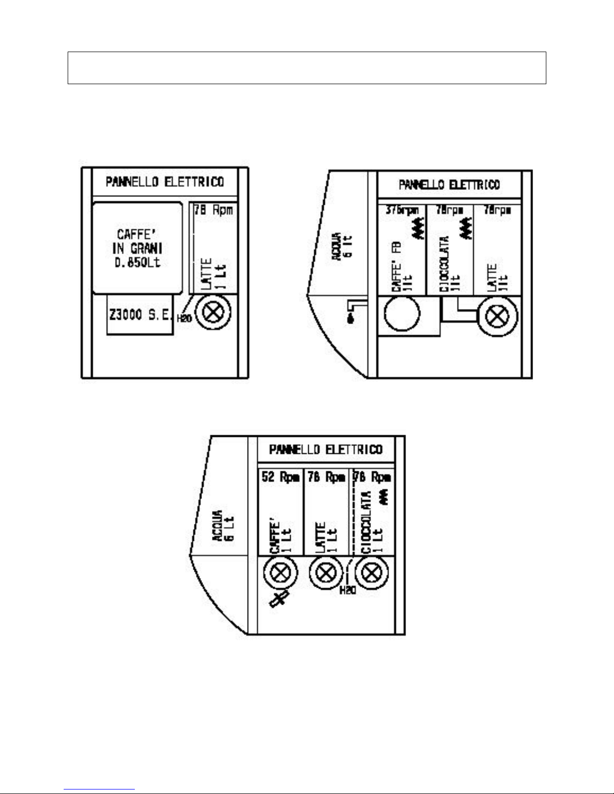
11- INTERNAL LAYOUTS
EXAMPLES OF INTERNAL LAYOUT
NOTE: THE FOLLOWING I LAYOUTS ARE ONLY GIVEN AS AN EXAMPLE FOR THE PURPOSE OF INDICATING THE CONFIGURATION
POSSIBILITIES. REFER TO THE TABLES SUPPLIED WITH THE MACHINE FOR THE ACTUAL LAYOUT.
Layout Koro Espresso
Layout Koro Fresh Brewer
Layout Koro Instant
Page 17
NW Global Vending – TECHNICAL MANUAL
This document was produced by MARK AC for the exclusive use of the technical personnel in the after-sales service.
. No part of this document may be divulged to a third party or reproduced partially or entirely without the prior permission of NW GLOBAL VENDING
. All rights reserved.
New dispenser “KORO” 07/10/2005 page 17 / 42
12 - ELECTRICAL SYSTEMS – CONNECTIONS
The machine is designed to operate under a single-phase voltage of 230 V AC (+5-10V)
It is protected with a main 15 A fuse on both phases.
With regard to the transformer: the primary winding is protected with a 125 mA fuse
the secondary winding is protected with a 1.25 mA fuse
It is fitted with a door opening safety switch.
The power cable can be supplied as standard feature and chosen among the following types:
1) HO5 RN – F copper with a 3 x 1.5 mm2 section
2) HO5 V V – F ,, ,, ,, ,,
3) HO5 V V – F ,, ,, ,, ,,
Fitted with a fixed SCHUKO ** plug.
NB **: it is possible that for some specific markets a cable with specific plug be fitted in accordance with the
regulations in force in that country.
In the event of replacement cables of exactly the same characteristics must be used.
Since the “KORO” vending machine is approved by an electrical safety certification institute (IMQ),
replacements with non-original components are not permitted.
Otherwise the electrical safety certificate and the warranty will be void.
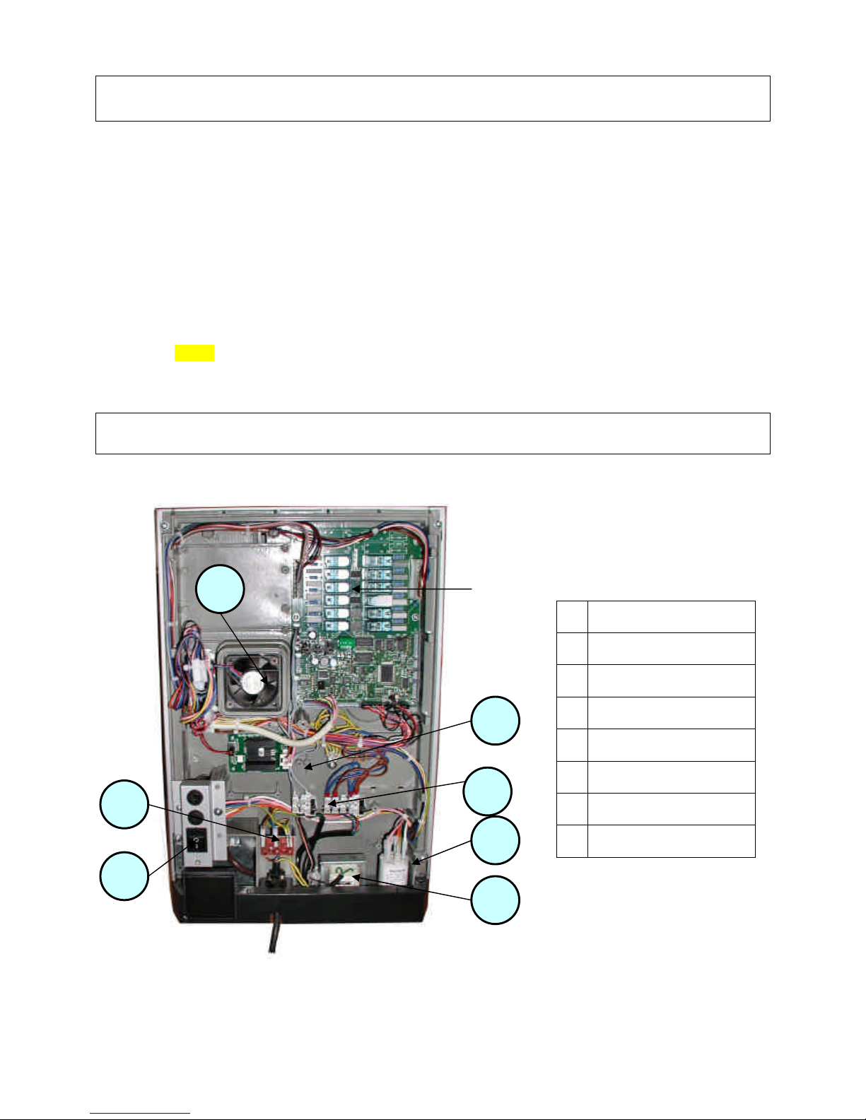
13 – CONNECTION OF ELECTRONIC BOARDS
1 Actuation board
2 Steam exhauster
3 Terminal strip
4 Switch and fuses
5 Boiler control board
6 Secondary winding fuses
7 Noise suppressor
8 Transformer
Scheda attuazioni
View of power supply unit compartment and actuation board
(Espresso version without protective casing)
8 2 3 5 6 7 4
Page 18
NW Global Vending – TECHNICAL MANUAL
This document was produced by MARK AC for the exclusive use of the technical personnel in the after-sales service.
. No part of this document may be divulged to a third party or reproduced partially or entirely without the prior permission of NW GLOBAL VENDING
. All rights reserved.
New dispenser “KORO” 07/10/2005 page 18 / 42
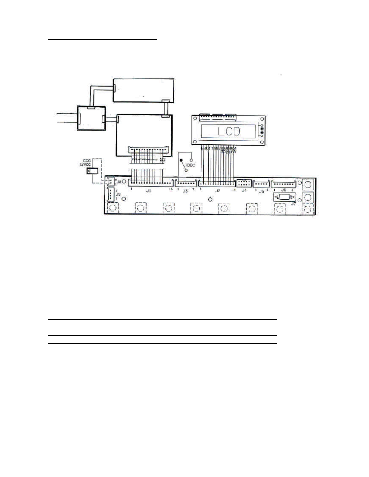
BOARD CONNECTION DIAGRAM
Signal DESCRIPTION
SAL
Power supply card
SM FB
Sigma brewer control board
SM
Actuation and control board
CCG
Mechanical general counter
SM 1
Push-button and display control card
LCD
Liquid crystal display
IDEC
Decaf. coffee door switch
NB: The above listed codes are indicated in the wiring diagrams and on information sheets supplied with the machine.
SM FB
SM
Actuation
J 14
J10 P5 P46
SAL J12
F
230 V
N
12 V 24 V
SM 1
Page 19
NW Global Vending – TECHNICAL MANUAL
This document was produced by MARK AC for the exclusive use of the technical personnel in the after-sales service.
. No part of this document may be divulged to a third party or reproduced partially or entirely without the prior permission of NW GLOBAL VENDING
. All rights reserved.
New dispenser “KORO” 07/10/2005 page 19 / 42
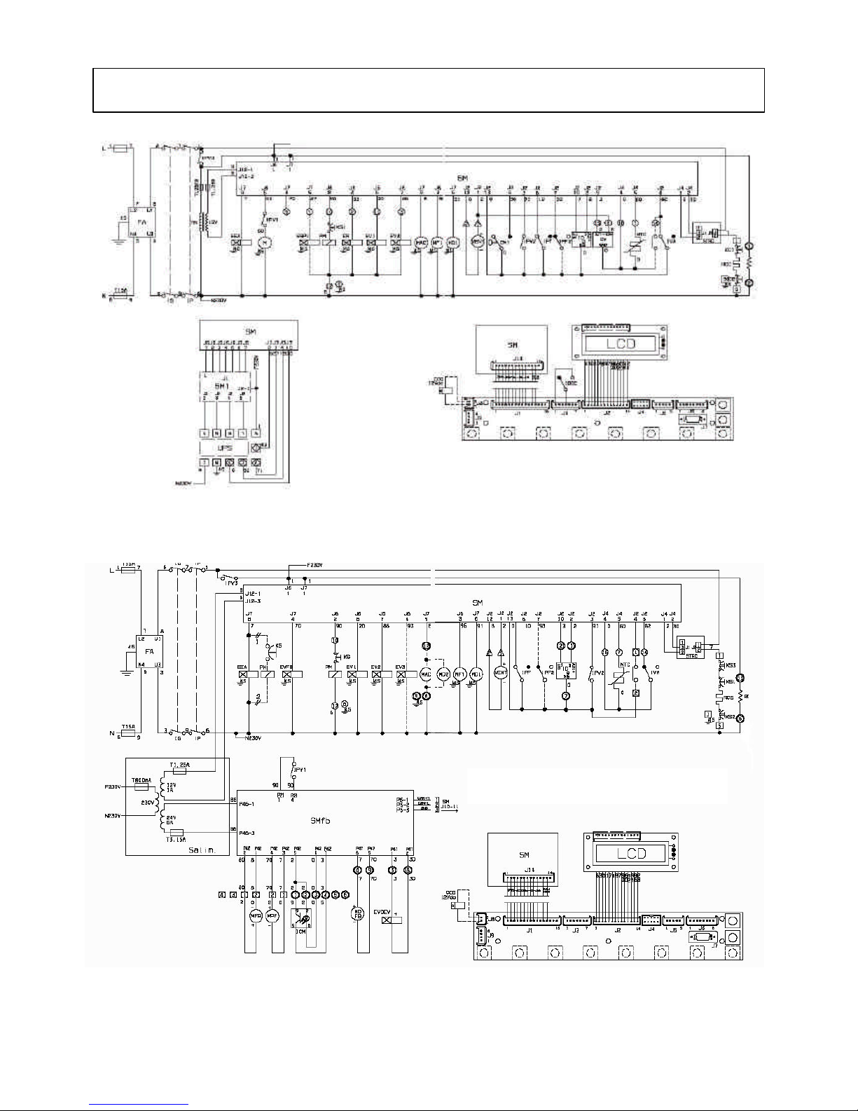
14
- WIRING DI
AGRAM
ESPRESSO
MODEL
FRESH BREWER
MODEL
Page 20
NW Global Vending – TECHNICAL MANUAL
This document was produced by MARK AC for the exclusive use of the technical personnel in the after-sales service.
. No part of this document may be divulged to a third party or reproduced partially or entirely without the prior permission of NW GLOBAL VENDING
. All rights reserved.
New dispenser “KORO” 07/10/2005 page 20 / 42
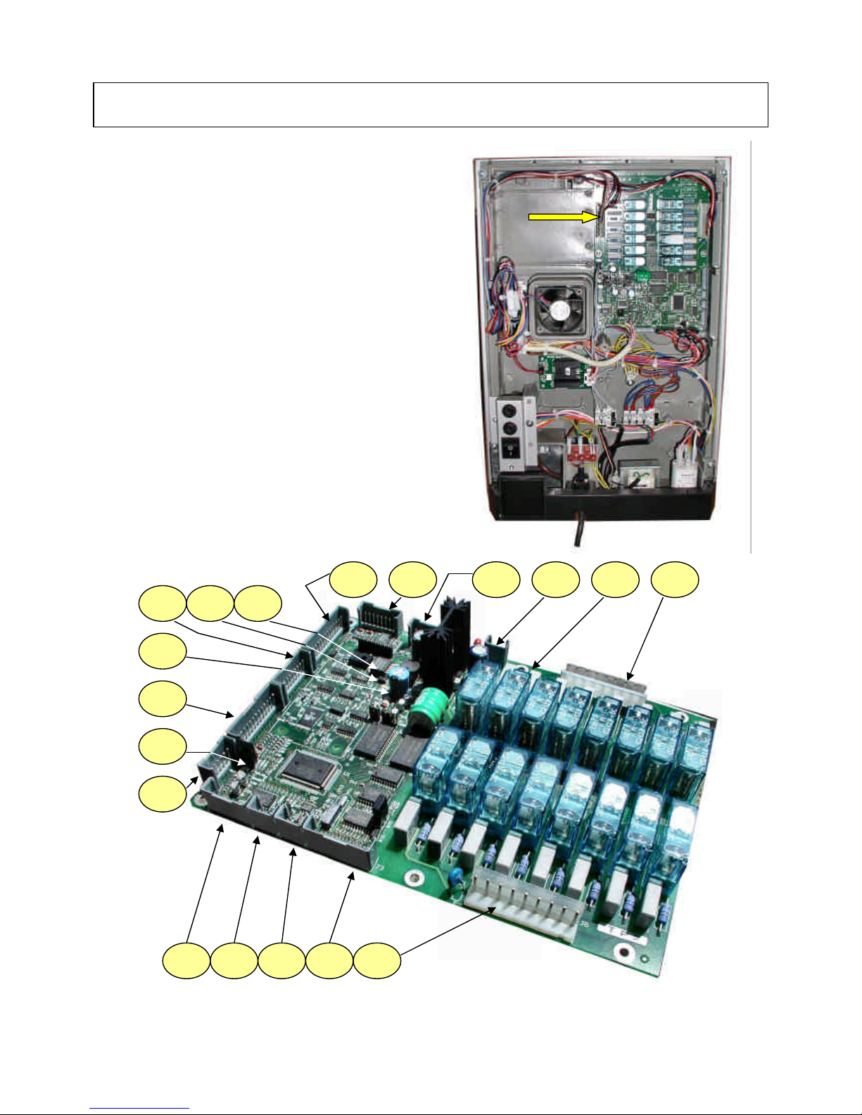
15 - ACTUATION BOARD - CONFIGURATIONS
ACTUATION BOARD
This board, placed at the back of the machine, (see Fig. 29)
processes the information from the push-button card and
from the payment system; it also controls the actuations, the
input signals and the boiler board.
The 15 VAC voltage necessary for operating the board is
supplied by the transformer, protected by a 125 mAT fuse on
the primary winding and by a 1.25 AT fuse on the secondary
winding; the voltage is rectified and stabilised directly by the
board.
This board houses the Flash EPROM. The control software of
the board is installed directly (via RS232) in the
microprocessor.
- The red LED (7) indicates the operating status of the
boiler heating element;
- The red LED (9) for resetting the CPU glows during the
board reset;
- The green LED (11) blinking indicates that the
microprocessor is working correctly;
- The yellow LED (12) indicates the presence of 12 V DC.
5 4 3 2 1 7 8 9 10 11 12 13 6 14 15 16 17 18
Page 21
NW Global Vending – TECHNICAL MANUAL
This document was produced by MARK AC for the exclusive use of the technical personnel in the after-sales service.
. No part of this document may be divulged to a third party or reproduced partially or entirely without the prior permission of NW GLOBAL VENDING
. All rights reserved.
New dispenser “KORO” 07/10/2005 page 21 / 42
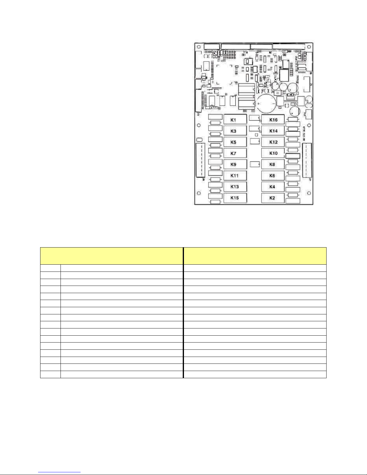
SM1: REFERENCE TO RELAY CODE AND ACTUATIONS - ESPRESSO / FB
ESPRESSO CONFIGURATION FRESH BREWER CONFIGURATION
K 1
Starting pump Pump
K 2
Not used Not used
K 3
Whipper motor 1 Whipper motor 1
K 4
Not used Not used
K 5
Coffee dispensing solenoid valve Instant prod. solenoid valve 3
K 6
Discharge solenoid valve 1 Fresh Brewer solenoid valve
K 7
Coffee brewer motor Not used
K 8
Discharge solenoid valve 2 Not used
K 9
Instant prod. solenoid valve 1 Instant prod. solenoid valve 1
K 10
Doser device motor 1 Doser device motor 1
K 11
Instant prod. solenoid valve 2 Instant prod. solenoid valve 2
K 12
Not used Not used
K 13
Not used Not used
K 14
Mains water inlet solenoid valve Mains water inlet solenoid valve
K 15
Not used Not used
K 16
Coffee grinder ratiomotor Doser device 2
1 - 230 V~ power users
2 - Input signal
3 - Can-Bus connection
4 - Can-Bus connection
5 - Relay expansion connection
6 - Boiler control probes
7 - Red LED - boiler heating element
8 - Input signal
9 - Red LED
10 - Not used
11 - Green LED
12 - Yellow LED
13 - To the push-button board
14 - Connector for board programming (RS232)
15 – Up-Key connector
16 - Board power supply (15Vac)
17 - Relays K1 to K16
18 - Connector for 230 V AC power users
Page 22
NW Global Vending – TECHNICAL MANUAL
This document was produced by MARK AC for the exclusive use of the technical personnel in the after-sales service.
. No part of this document may be divulged to a third party or reproduced partially or entirely without the prior permission of NW GLOBAL VENDING
. All rights reserved.
New dispenser “KORO” 07/10/2005 page 22 / 42
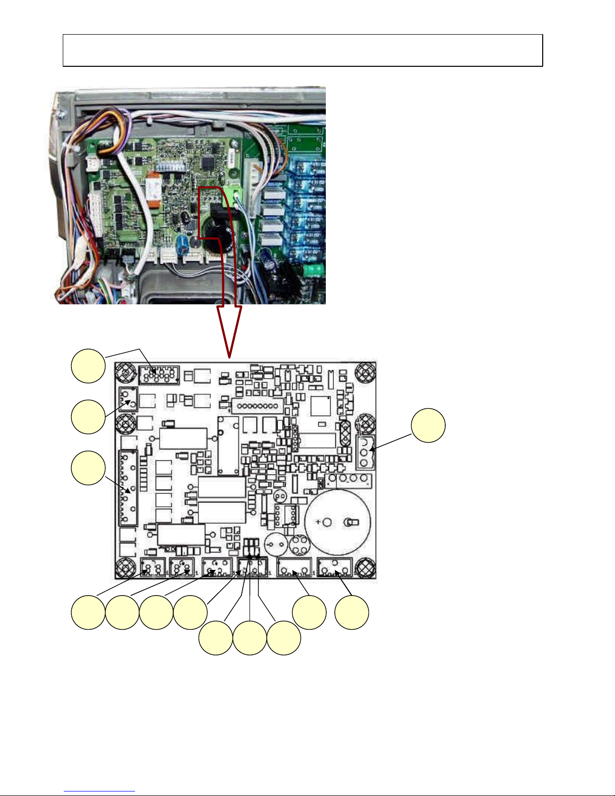
16 - SIGMA BREWER CONTROL BOARD
4 3 2 1 13 12 11 6 5 10 9 8 7
This board, located at the back of the machine, is
additional to the actuation board and controls the
SIGMA BREWER unit function only for the FB version.
(see photo without protective casing)
It processes the information from the brewer unit and
controls its functions.
The board also controls the dispensing of fresh product
and the flow diverter solenoid valve from
spout/external nozzle.
The 24 VAC voltage necessary for operating the board
is supplied by the transformer, protected by a 800 mAT
fuse on the primary winding and by a 3.15 AT fuse on
the secondary winding; the voltage is rectified and
stabilised directly by the board.
- The green LED (7) indicates the presence of +5 V;
- The green LED (8) indicates the presence of 34 V
DC variable;
- The green LED (9) indicates the presence of 34 V
DC.
1 - To Sigma brewer unit
2 - Not used
3 - MDFB and EVDEV
4 - Board power supply 24Vac
5 - Not used
6 - Not used
7 - Green LED +5V
8 - Green LED 34Vdc variable
9 - Green LED 34 Vdc
10 - Tray detection micro-switch
11 - Tray detection micro-switch
12 - Can-bus with actuation board
13 - Can-bus with actuation board
DETAIL OF REAR SECTION WITHOUT PROTECTIVE CASING
Page 23
NW Global Vending – TECHNICAL MANUAL
This document was produced by MARK AC for the exclusive use of the technical personnel in the after-sales service.
. No part of this document may be divulged to a third party or reproduced partially or entirely without the prior permission of NW GLOBAL VENDING
. All rights reserved.
New dispenser “KORO” 07/10/2005 page 23 / 42
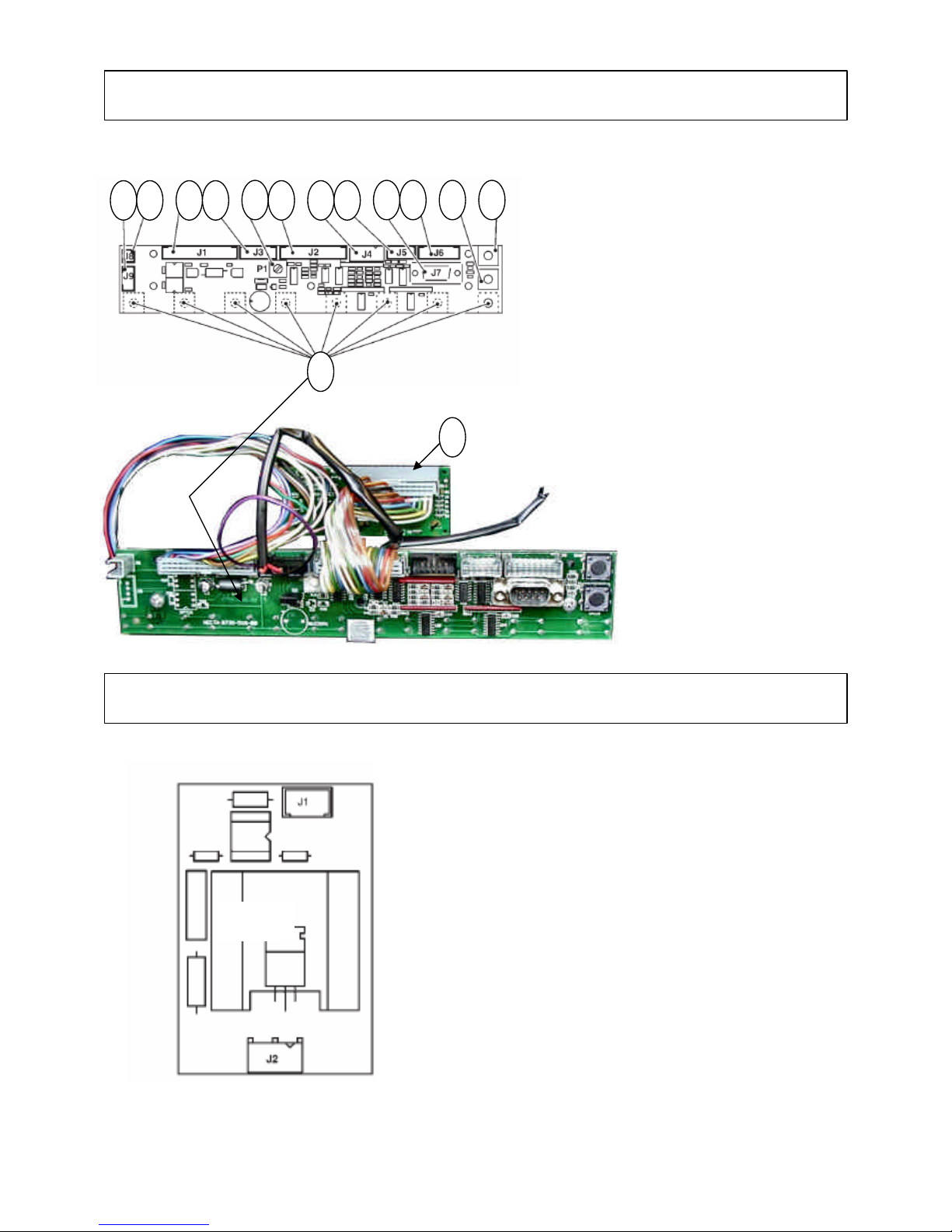
17 - PUSH-BUTTON BOARD
18 - BOILER CONTROL BOARD
1 - Selection buttons
2 - Not used
3 - To mechanical counter (optional)
4 - To actuation/CPU board
5 - Input
6 - Display adjustment trimmer
7 - To display
8 - 12 Vdc validators
9 - Not used
10 - RS232 serial port
11 - Not used
12 - Programming access button
13 - Wash button
14 - Display card
Triac board
This board is controlled by the machine board and is
powered under 230 V AC.
It used for controlling and starting the boiler heating
element.
Connector J2 is connected to a 230V AC phase
Connector J1 receives the information from the SM
board
that sends a consent signal to activate the triac for the
power supply to the heating element.
6 4
STRC
2 3 5 7 8 9 10 11 12 13 1 14
Page 24
NW Global Vending – TECHNICAL MANUAL
This document was produced by MARK AC for the exclusive use of the technical personnel in the after-sales service.
. No part of this document may be divulged to a third party or reproduced partially or entirely without the prior permission of NW GLOBAL VENDING
. All rights reserved.
New dispenser “KORO” 07/10/2005 page 24 / 42
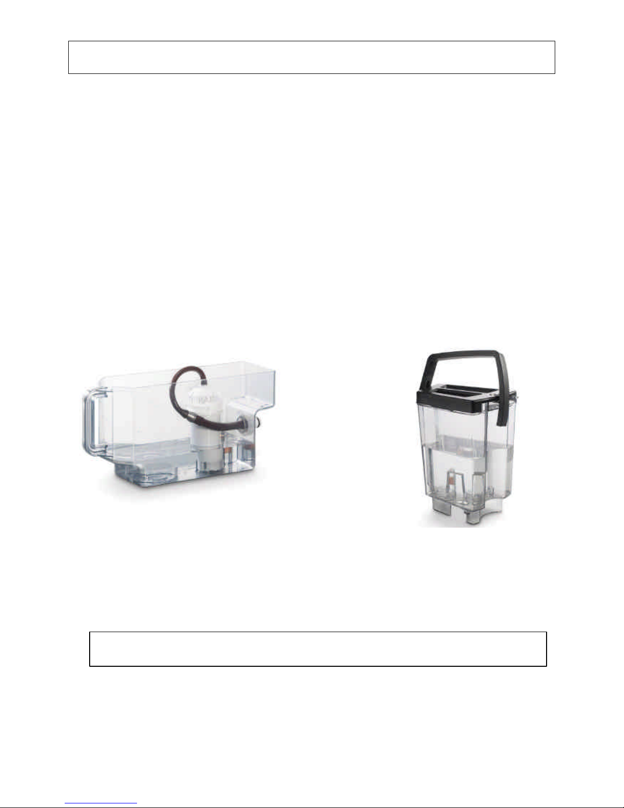
19 – AIR-BREAK & BOILERS
In the currently coded versions the use of an air-break is not planned; in the instant and fresh brewer versions the
open-top boiler is used, which is equipped with a level control system and therefore the relevant functions are
incorporated in the boiler (see next paragraph).
In the espresso versions an internal water supply tank is used, having the functions of the air-break.
There will be in any case some versions with water supply from the mains, where an air-break will be fitted;
therefore the proper documentation will be supplied later.
The air-break is a functional unit that has the function of keeping the water level constant and to have signal
indicating the lack of water from the mains, and in such event it allows the completion of the current selection.
Furthermore (in the espresso version) it serves the purpose of have a water reserve at atmospheric pressure, so
that the pump can draw the water dose needed for the selection and send it to the espresso boiler without pressure
changes that may affect the volumetric counter reading.
The water level is ensured by a float that triggers a microswitch, keeping the level between a factory set minimum
and maximum (it very important not to replace the microswitch with any one of different mechanical
characteristics, as a variety of malfunctions may occur).
Furthermore, in the event of failure to the maximum level microswitch, an overflow hole allows the water to be
conveyed through a tube and to the safety device fitted on the water inlet solenoid valve, thus causing its
mechanical lock (such safety device is triggered also in the event of a power failure).
Water supply tank for the Espresso version,
complete with softener filter and magnetic float
Water supply tank for the Instant &
fresh Brewer version
The water supply tanks are preset for the use of internal softener filters and are fitted with a magnetic
level signal that trigger a sensor located inside the vending machine.
Page 25
NW Global Vending – TECHNICAL MANUAL
This document was produced by MARK AC for the exclusive use of the technical personnel in the after-sales service.
. No part of this document may be divulged to a third party or reproduced partially or entirely without the prior permission of NW GLOBAL VENDING
. All rights reserved.
New dispenser “KORO” 07/10/2005 page 25 / 42
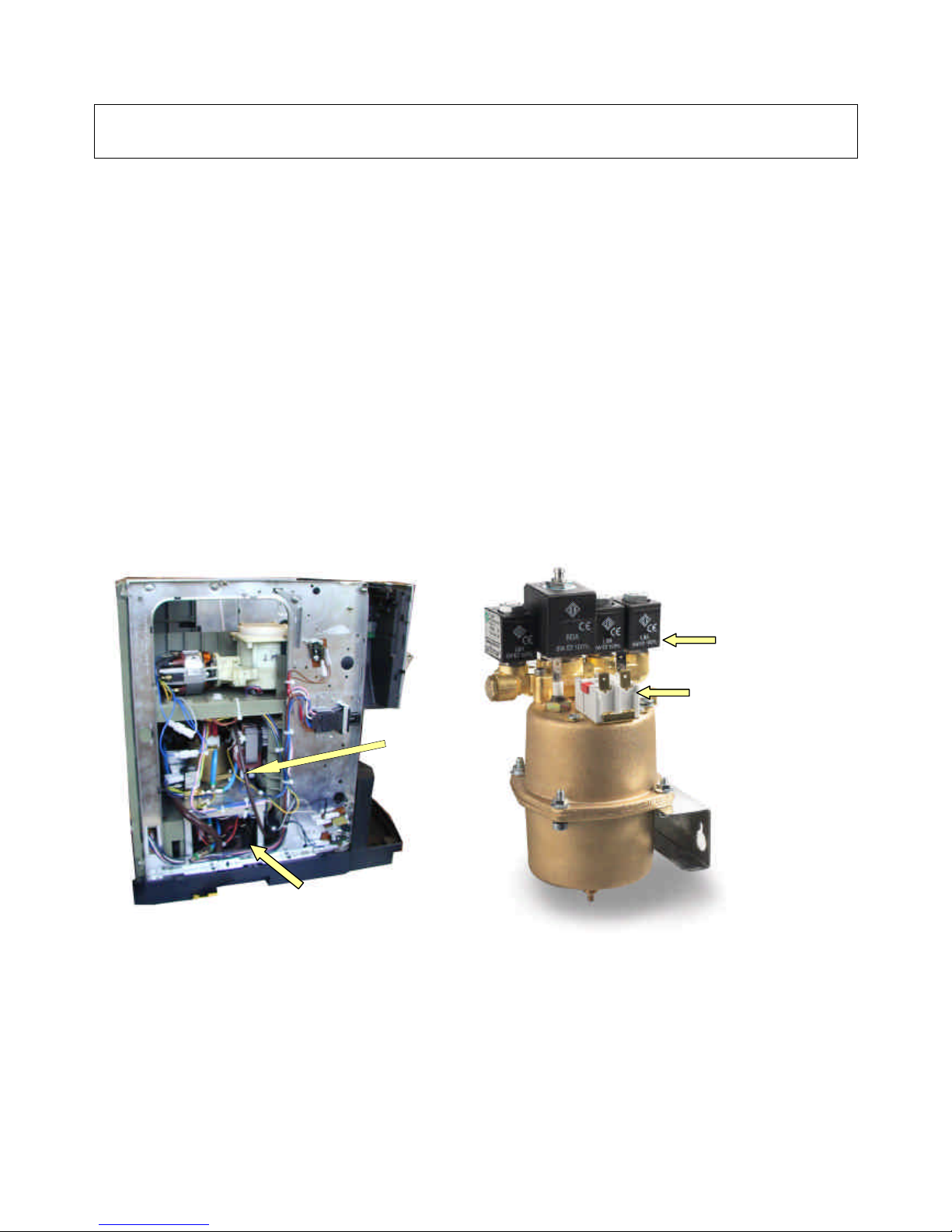
19.1 – BOILERS
For the KORO model there are three base versions:
1) Espresso version, fitted with a pressure boiler, very similar to the one used in the entire range.
2) Instant version, fitted with only the open-top instant boiler, also fitted with a new design level control
system.
3) Fresh-brew version, fitted with only the open-top instant boiler used in the Instant version.
The espresso boiler is the same used for KIKKO models, therefore with the same well known and
established characteristics and reliability.
The open-top boiler for the Instant / FB version is a new and specific design with the feature of being
molded from thermoplastic material with specific technical characteristics.
PRESSURE BOILERS
SONDA NT
Side view without protective casing
– pressure boiler inspection side
Pressure boiler removed from the machine
Bipolar safety
thermostat
Solenoid valve assembly
(Three 2-way valves + one
3-way valve)
Vibration pump
Pressure
boiler
Page 26
NW Global Vending – TECHNICAL MANUAL
This document was produced by MARK AC for the exclusive use of the technical personnel in the after-sales service.
. No part of this document may be divulged to a third party or reproduced partially or entirely without the prior permission of NW GLOBAL VENDING
. All rights reserved.
New dispenser “KORO” 07/10/2005 page 26 / 42
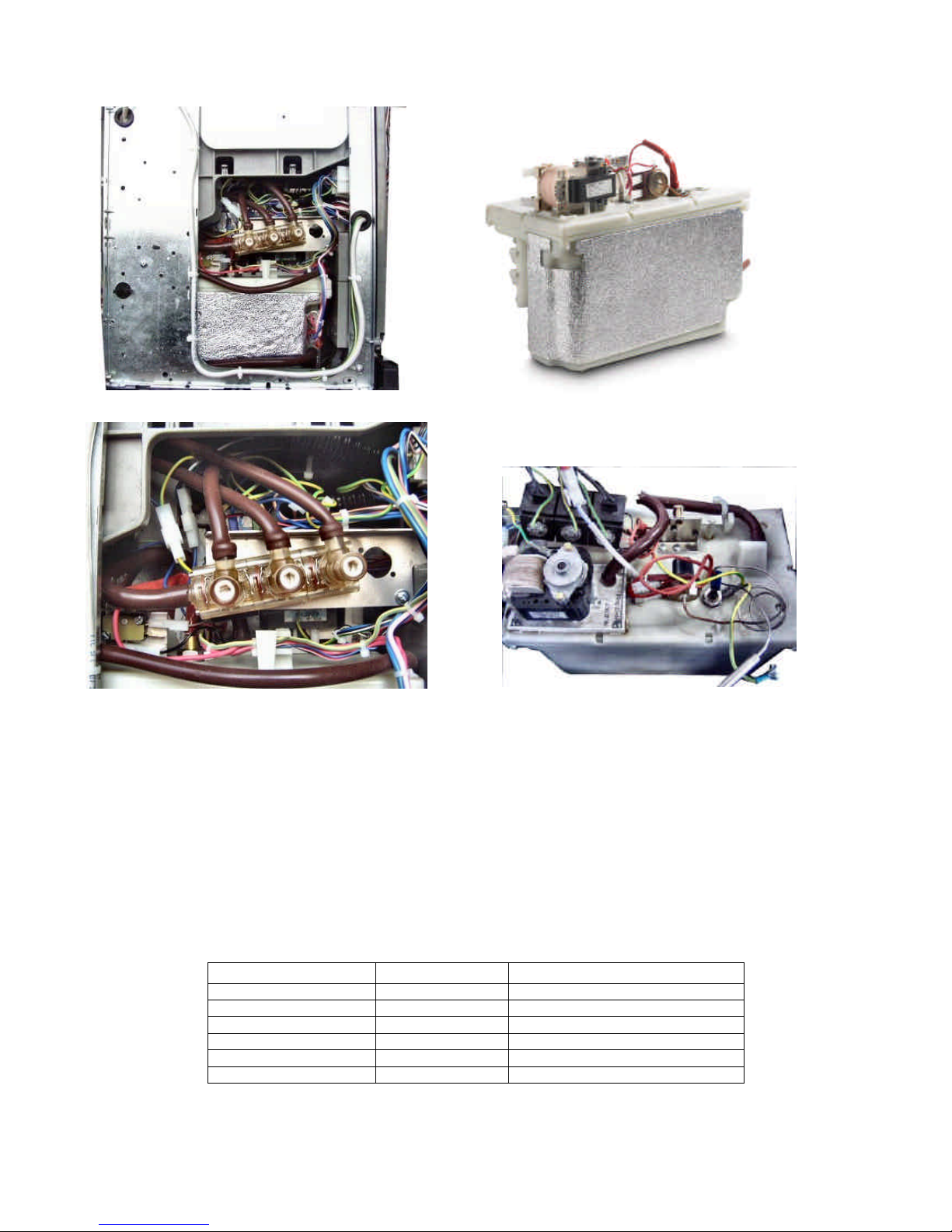
OPEN-TOP BOILER
Boiler temperature °C Value in ohm Allowed tolerance
0 35875 +/-7 ohm
25 12000 +/- 4 ohm
50 2900 ,,
85 1475 ,,
90 1260 ,,
100 963 ,,
TERMOSTATO
CALDAIA
NOTE: The open-top is made of special thermoplastic material and coated with insulat
ing material for more efficient heat
insulation; two overheating protections are fitted for safety.
1) Dry operation protection.
2) Anti-boiling protection.
In the event of failure to the control system and boiler without water, thermostat 1 is triggered
at approximately 125°C and
disconnects the power supply; in order to reactivate everything the malfunction must be identified and the thermostat must be
reset by pressing the central red button.
In the event of failure to the control system and the boiler full, upon reaching boiling temperature, as the steam exits from tube A
it touches and triggers the two thermostats 2.
Proceed as above to reset them; see specific chapter to identify the type of malfunction.
See relevant section in the functional unit
manual for details, photos and complete description: BOILERS
The internal temperature control (in both boilers) is by means of an NTC type electronic probe fitted with an internal 12K ohm (±
4 ohm) resistance at a temperature of 25°C.
SIDE VIEW WITHOUT PROTECTIVE CASING –
OPEN-TOP BOILER COMPARTMENT
OPEN
-
TOP BOILER
O
PEN-TOP BOILER – DETAIL OF SOLENOID VALVES AND OVERHEATING PROTECTIONS
Page 27
NW Global Vending – TECHNICAL MANUAL
This document was produced by MARK AC for the exclusive use of the technical personnel in the after-sales service.
. No part of this document may be divulged to a third party or reproduced partially or entirely without the prior permission of NW GLOBAL VENDING
. All rights reserved.
New dispenser “KORO” 07/10/2005 page 27 / 42
20
– PUMPS AND
BY
-
PASS
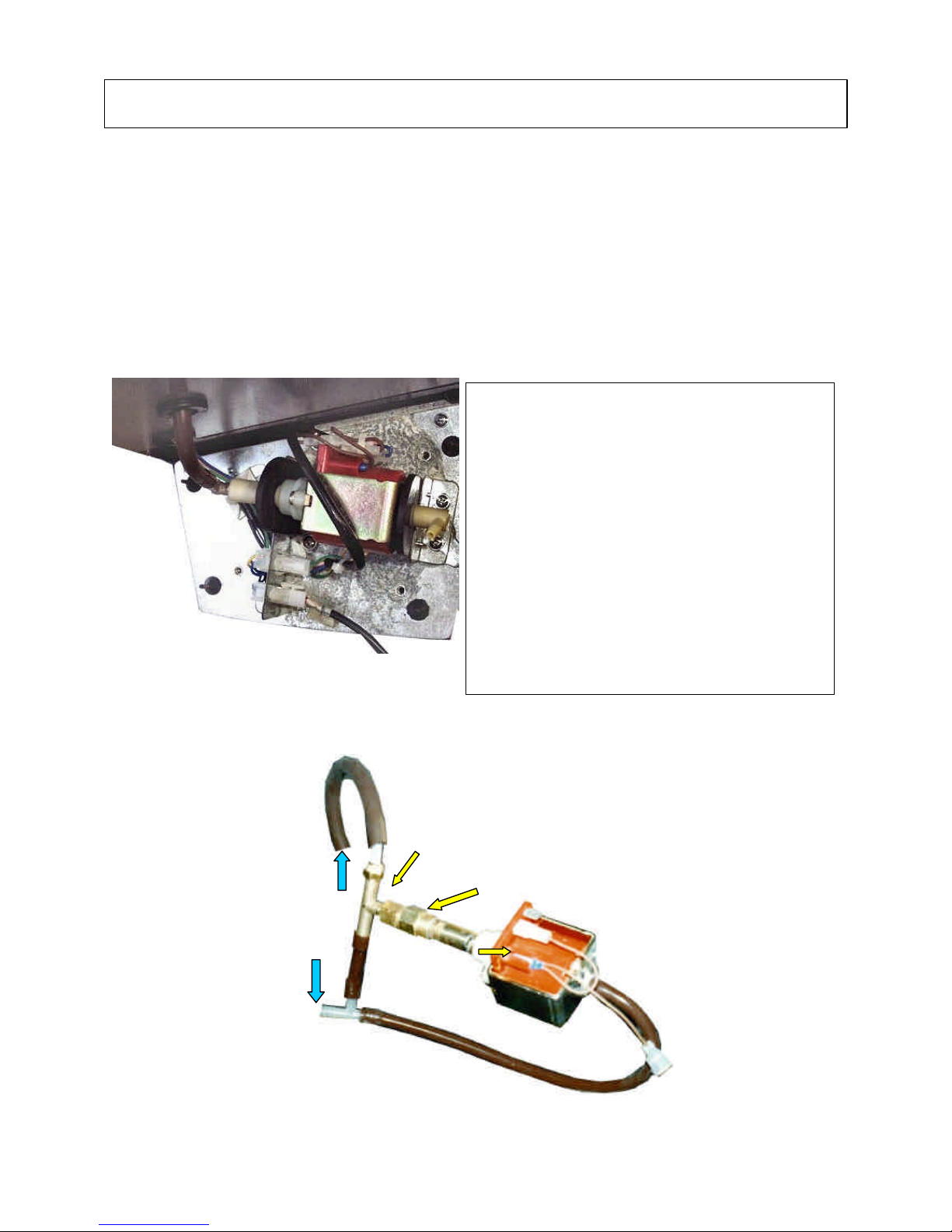
In order to supply water to the espresso boiler a vibration pump used, which is the same used in the entire H&C
range of Necta.
The application is specific, as pump, boiler, TRIAC circuit and connections are positioned inside the espresso
module and easily accessible after opening the compartment wall, closed by only two screws and a quick snap
fastener (see Page 16)
This solution ensures maximum access for maintenance and hygiene, it also allows the option of using
configurations with two espresso modules as an alternative to other two modules, and even mixed modules
espresso/instant/fresh-brew.
The pump has overheating protection in case of continuous or dry operation by means of a 90°C self-reset
klixon. It is fitted with a by-pass at the outlet to ensure correct and consistent dispensing pressure.
The by-pass is factory pre-set at 12 bar.
The pump is activated by relay K 8 (see previous page for the pictures).)
The pump is located in the espresso boiler unit.
In the event of malfunctions the pump can be
replaced with a new one.
In order to access to it, t
he brewer unit must be
removed (Fig. 1).
Therefore the boiler unit protective casing must be
opened (Fig. 2) undoing the two fastening screws.
The PUMP is located on the left-
hand side and is
mounted on two rubber anti-vibration elastic supports.
Disconne
ct the connection cables and remove after
undoing the special screws.
NEVER change the setting of the bypass, especially
adjusted at the factory, if the malfunction is due to
clogging from calcium deposits; replace with the
complete check-valve spare part set.
If the malfunction was due to triggering of the klixon,
replace it with an identical one.
POMPA
Klixon
Overheating
protection
BY PASS
CHECK-VALVE
WATER INLET
PUMP REMOVED FROM THE BOILER UNIT
Page 28
NW Global Vending – TECHNICAL MANUAL
This document was produced by MARK AC for the exclusive use of the technical personnel in the after-sales service.
. No part of this document may be divulged to a third party or reproduced partially or entirely without the prior permission of NW GLOBAL VENDING
. All rights reserved.
New dispenser “KORO” 07/10/2005 page 28 / 42
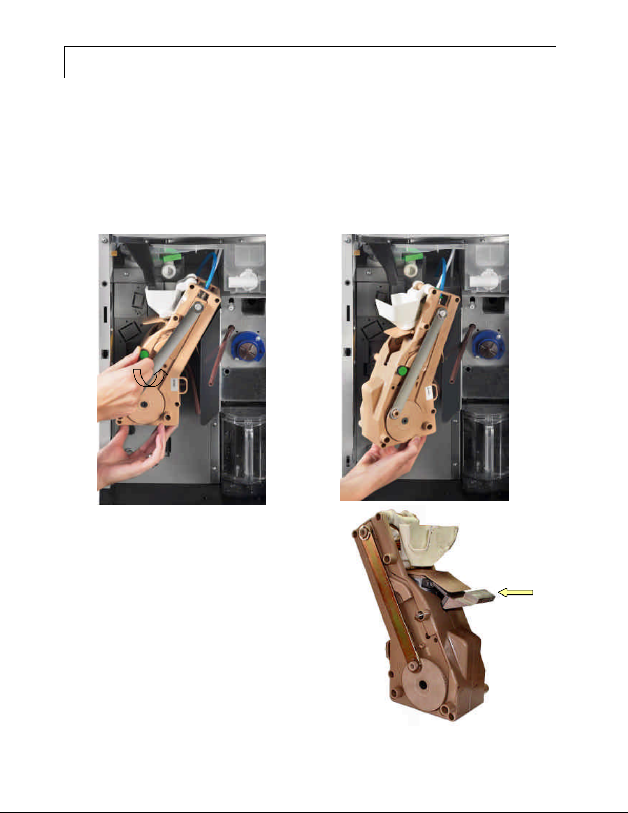
The espresso version is equipped with the new Z3000 unit, used in three specific versions (refer to the specific Z3000
service manual). In any case it is an evolution, with many improvements, of the model Z2000, more specifically planned for
the following versions:
1) Standard version, which is equivalent to the old Z2000 but with a simpler structure.
2) Variable chamber version, which permits brewing with variable coffee doses.
3) Larger chamber version, which permits selections with more coffee compared to the maximum possible with the base
unit.
A heating system has been designed for all versions, for the purpose of increasing the temperature of the first coffee.
A specific brewer unit for filtered coffee, SIGMA BREWER, is used in the FB version.
For further details on the functional units refer to the specific H&C functional unit manuals “BREWER UNITS”.
The Espresso brewer unit uses that is ground on the spot by the grinder and doser unit, specifically designed for this model
and that also uses a particular method of metering the ground coffee dose.
The FB unit uses specific coffee, already ground to an optimum grade for quick and adequate brewing.
21
– ESPRESSO & FB BREWER
UNITS
In order to remove the unit from the vending
machine, undo the brass knurled knob, disconnect
the unit's hydraulic connections, undoing the upper
tube fastening nut and release the dispensing tube.
When removing the unit, make sure it positioned at
the upper dead centre (Fig. 1). To reposition it,
follow the same procedure in the reverse order,
again making sure it positioned at the upper dead
centre, carefully inserting it onto the special
positioning pins.
D
ETAIL OF BASE
Z3000
UNIT BEING REMOVED
Heating plate
functioning by
contact with the
brewing chamber
Page 29
NW Global Vending – TECHNICAL MANUAL
This document was produced by MARK AC for the exclusive use of the technical personnel in the after-sales service.
. No part of this document may be divulged to a third party or reproduced partially or entirely without the prior permission of NW GLOBAL VENDING
. All rights reserved.
New dispenser “KORO” 07/10/2005 page 29 / 42
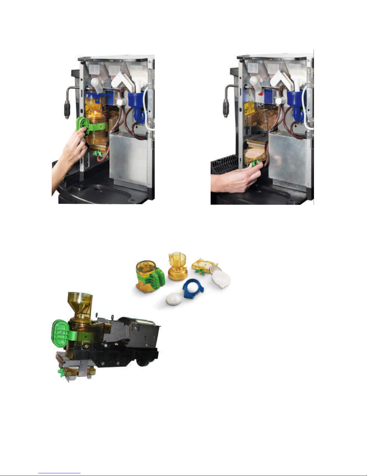
D
ETAIL OF SIGMA BREWER UNIT BEING REMOVED
DETAIL OF BREWING CHAMBER
BEING REMOVED
D
ETAIL OF LOWER FILTER BEING
REMOVED
SIGMA BREWER UNIT REMOVED FROM
THE VENDING MACHINE
BREWING CHAMBER AND FILTER COMPLETELY DISASSEMBLED
The SIGMA BREWER is a new unit
especially designed for the vending
machine Koro, FB version.
It is a highly innovative and advanced unit
that allows disassembly of parts to be
cleaned in a few instants.
Furthermore, it uses a system with air
pressure for brewing; such system permits
greater extraction of the coffee flavourings.
Page 30
NW Global Vending – TECHNICAL MANUAL
This document was produced by MARK AC for the exclusive use of the technical personnel in the after-sales service.
. No part of this document may be divulged to a third party or reproduced partially or entirely without the prior permission of NW GLOBAL VENDING
. All rights reserved.
New dispenser “KORO” 07/10/2005 page 30 / 42
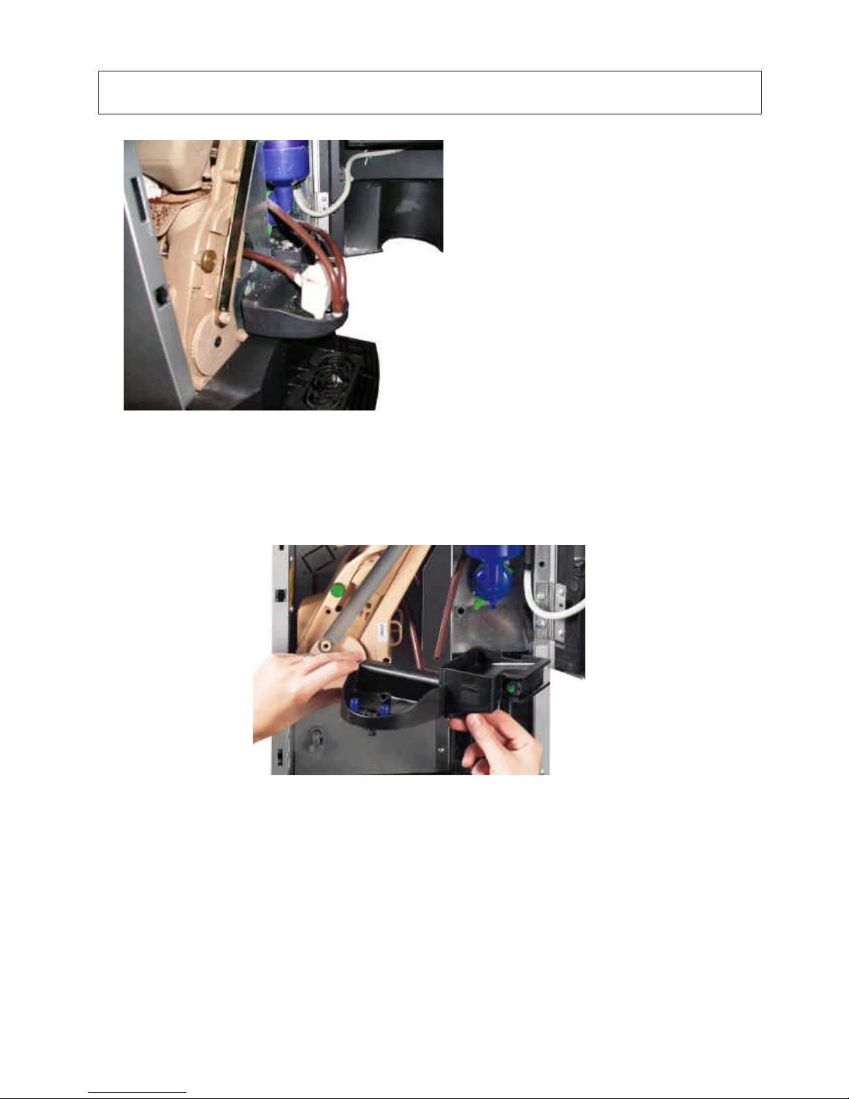
22
– SPOUTS ASSEMBLY
Because of the size of the vending machine
FIXED SPOUTS have been designed.
The spouts are mounted onto a tray that is
easy to remove for daily cleaning.
EXTERNAL VIEW OF SPOUTS ASSEMBLY
DETAIL OF SUPPORT TRAY BEING REMOVED
Page 31
NW Global Vending – TECHNICAL MANUAL
This document was produced by MARK AC for the exclusive use of the technical personnel in the after-sales service.
. No part of this document may be divulged to a third party or reproduced partially or entirely without the prior permission of NW GLOBAL VENDING
. All rights reserved.
New dispenser “KORO” 07/10/2005 page 31 / 42
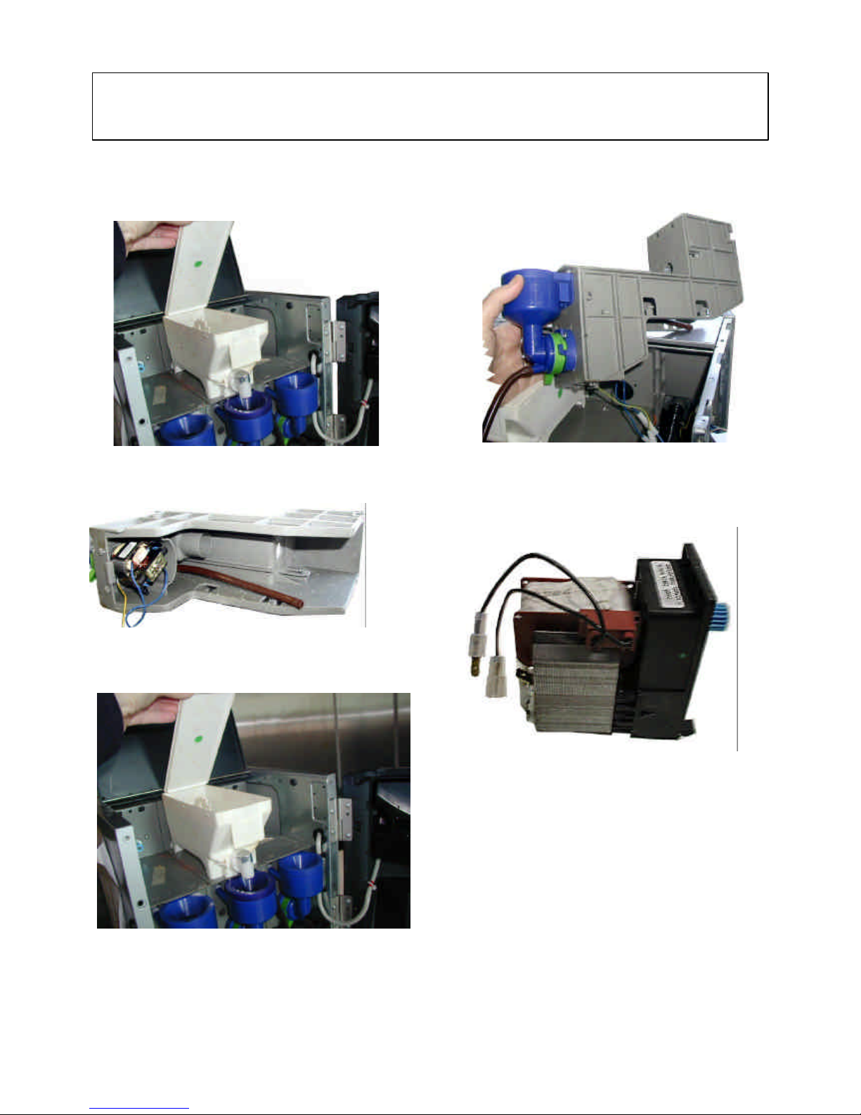
In According to new market requirements, it was necessary to design new solutions using quick fastening
without any screws, to allow easy access for maintenance, as well as quick changes to the layout by means of
preassembled modules.
23 – DOSER DEVICES AND POWDER PRODUCT
CONTAINERS
Standards components are used, already adopted in
other applications, but in a new support and with
newly designed specific powder containers,
comprising also the mixer assembly.
The system is modular and of the same width as a
powder container.
It was designed for quick and easy removal as
required by the particular type of machine.
INSTANT PRODUCT CONTAINER OPEN AND
BEING REMOVED
MIXER RATIOMOTOR ASSEMBLY
VIEWED FROM BELOW
MIXER RATIOMOTOR ASSEMBLY
BEING REMOVED FROM ITS SEAT
RATIOMOTOR REMOVED FROM ITS SEAT
INSTANT PRODUCT CONTAINER OPEN
AND BEING REMOVED
Page 32
NW Global Vending – TECHNICAL MANUAL
This document was produced by MARK AC for the exclusive use of the technical personnel in the after-sales service.
. No part of this document may be divulged to a third party or reproduced partially or entirely without the prior permission of NW GLOBAL VENDING
. All rights reserved.
New dispenser “KORO” 07/10/2005 page 32 / 42
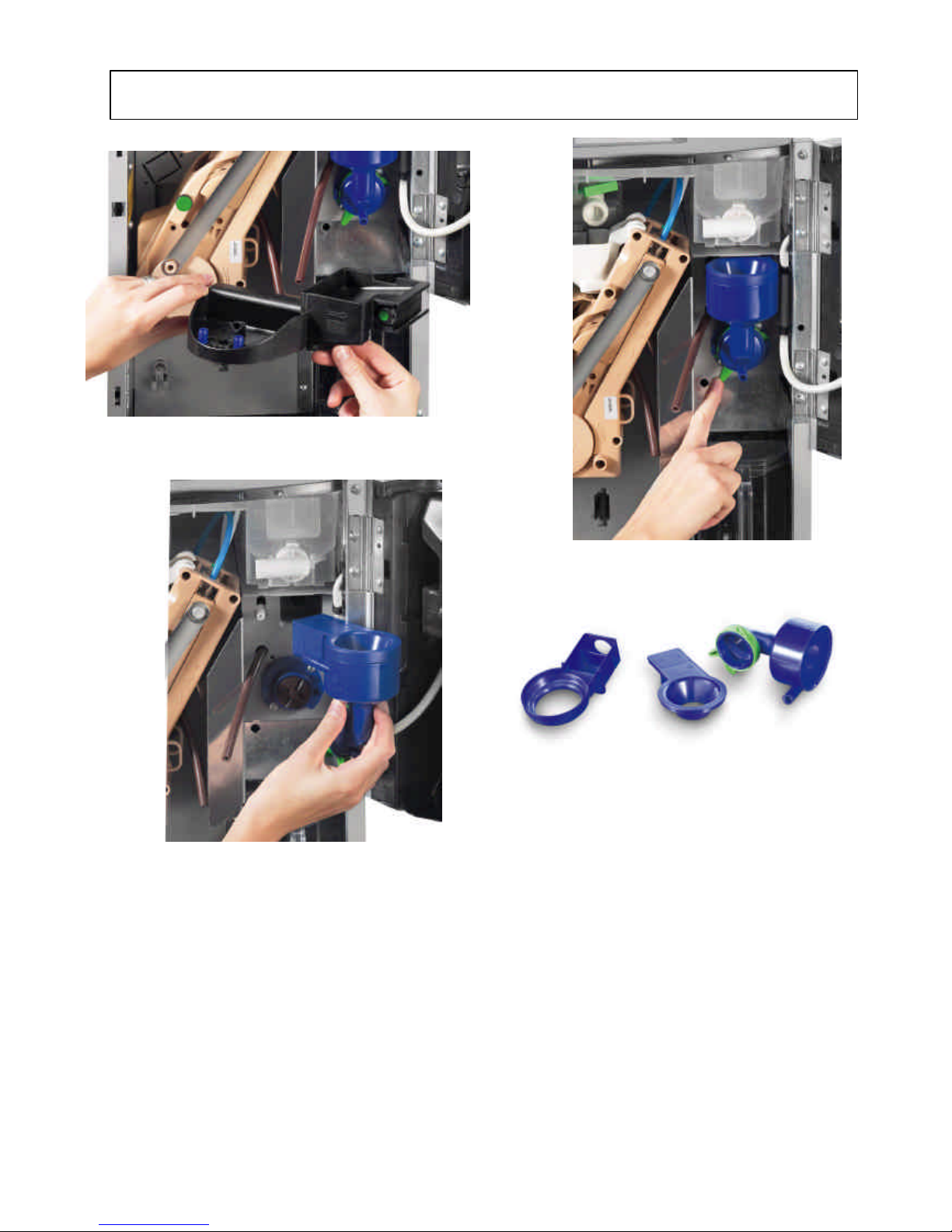
24
– MIXER UNIT
The mixers are newly designed, although many components are developed from the ones used in previous
models.
More specifically, the release and opening system of the external assembly is new, while the motor and the
water tightness system are identical.
The new system permits easier disassembly for daily cleaning.
For further details and technical information refer to the specific “Service Manual”.
TRAY UNDER THE MIXER BEING REMOVED
MIXER IN EXTRACTION POSITION:
DETAIL OF RELEASE LEVER
PLASTIC COMPONENTS OF DISASSEMBLED MIXER
MIXER HAVING THE EXTERNAL PARTS THAT NEED
DAILY HYGIENE BEING REMOVED
Page 33
NW Global Vending – TECHNICAL MANUAL
This document was produced by MARK AC for the exclusive use of the technical personnel in the after-sales service.
. No part of this document may be divulged to a third party or reproduced partially or entirely without the prior permission of NW GLOBAL VENDING
. All rights reserved.
New dispenser “KORO” 07/10/2005 page 33 / 42
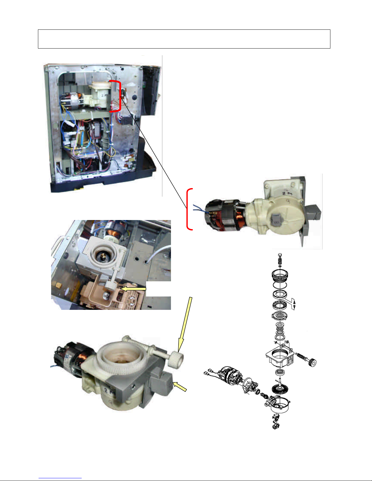
25
– DOSER GRINDER UNIT
The coffee grinder is a new design and the ground coffee dose is
determined via software setting and by means of a sensor that counts
the number of revolutions of the grinding wheels (see view below).
Therefore, it is very important that the mechanical adjustments to the
grade of grinding be checked very frequently. In order to get a dose of
7 grams of coffee a certain number of revolutions is counted; by
increasing or decreasing such value the amount increases or decreases.
It is therefore possible to set selections with different coffee doses.
It is therefore clear that it is very important to keep the adjustment of
the grinding wheels constant to obtain accurate coffee doses.
Especially in the first period of use (1000-2000 selections), because of
the greater wear due to the initial settling.
The adjustment can be performed also approximately by regularly
checking the weight of the ground coffee and its grade of grinding.
The motor winding is fitted with a self-reset overheating protection.
Flat-type grinding wheels are used.
For further information refer to the specific manual.
COFFEE GRINDER (PERSPECTIVE VIEW)
COFFEE GRINDER - VIEW IN OPERATING POSITION
Side view without protective casing
– coffee grinder unit position area
COFFEE GRINDER (VIEW FROM BELOW)
SENSOR SIDE
EXPLODED VIEW
DISTANCE TO
BE CHECKED
Knob for adjusting the distance
between grinding wheels
Ground outlet exit port
Page 34
NW Global Vending – TECHNICAL MANUAL
This document was produced by MARK AC for the exclusive use of the technical personnel in the after-sales service.
. No part of this document may be divulged to a third party or reproduced partially or entirely without the prior permission of NW GLOBAL VENDING
. All rights reserved.
New dispenser “KORO” 07/10/2005 page 34 / 42
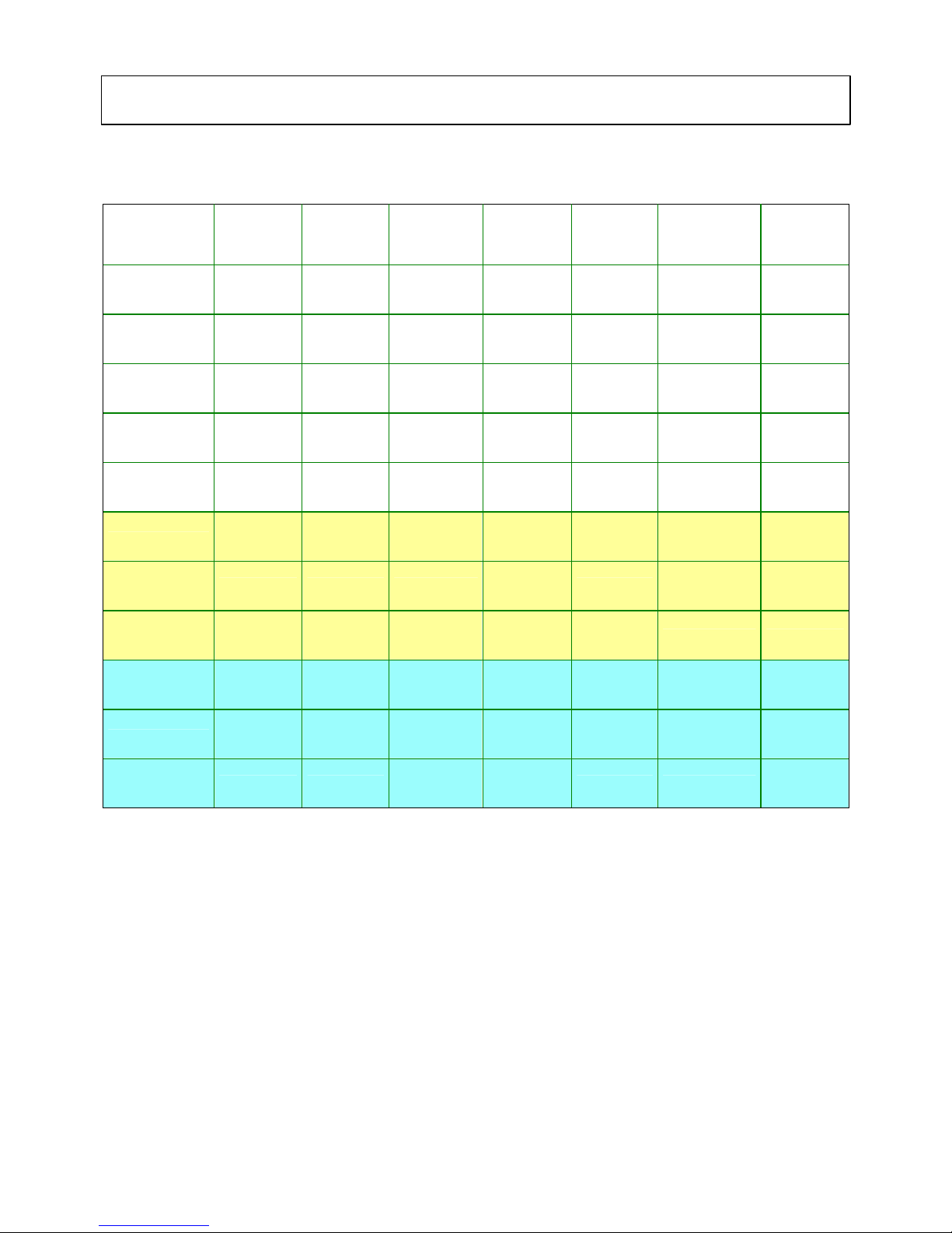
The software is programmed by default with the most suitable settings for the relevant market.
The following table is an example, and are for the Italian market settings, and the correct and updated
settings are indicated in the tables supplied with the machine.
Selection Remarks Coffee
beans
Coffee
Instant
Water
c.c.
Powder
g
Fresh-brew
coffee
g
Remarks
NOTE 1
The water flow in the mixers is approximately 10 c.c. per second and it is given as a guideline, as there are
many variables that can affect the accuracy.
The liquid dose is determined by the flow-meter pulse counting (volumetric counter).
Both versions (Instant and Espresso) use an electromechanical vibration pump (with the espresso boiler) for
the water flow, therefore the liquid dose in both versions is measured in flow-meter pulses (fmp).
NOTE 2
To be noted that the number of pulses does not change in a linear manner (i.e. double the amount of water
does not correspond to double the number of pulses), however the counter varies the accuracy according to
the water flow velocity, and namely:
For espresso coffee it is reduced considerably because of the coffee compress reaction that slows down the
water flow, while it is accelerated in the instant drinks selections, since there are no obstructions to the
water flow. Therefore, in the event of changing the doses set at the factory, some measurements must be
made using measuring containers.
26 – POWDER AND LIQUID DOSE TABLES
Page 35
NW Global Vending – TECHNICAL MANUAL
This document was produced by MARK AC for the exclusive use of the technical personnel in the after-sales service.
. No part of this document may be divulged to a third party or reproduced partially or entirely without the prior permission of NW GLOBAL VENDING
. All rights reserved.
New dispenser “KORO” 07/10/2005 page 35 / 42
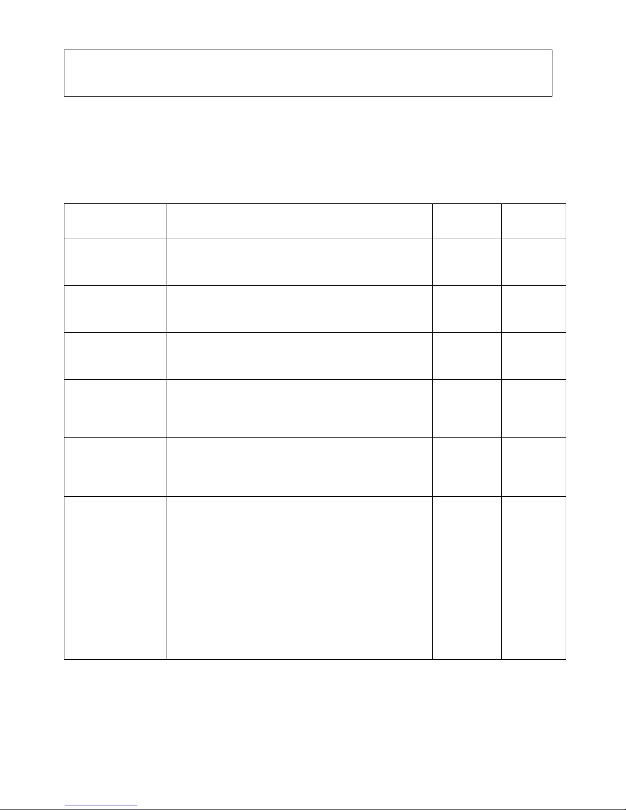
The vending machine KORO was designed to operate for a long time without malfunctions; however in order to
ensure excellent reliability periodic maintenance is necessary.
Such maintenance must be performed according to the number of selections made and the time lapsed.
Periodic and correct maintenance ensures reliability, constant quality and also guarantees safety standards over
time.
The following table indicates the functional units that must be subjected to periodic maintenance and the
frequency of maintenance. For the operations to be carried out, refer to the specific Functional unit manuals.
Name of unit
DESCRIPTION OF OPERATION
N. of
selections
Max
frequency
Espresso brewer
unit
1) Check state of filters and wear of silicone O-ring seal
2) Replace upper and lower filters and related seals
3) Descale the internal vent hole and lubricate with specific
food-safe grease
5000
8000
30.000
1 month
6 months
annual
Fresh brewer unit
1) Check state of filters and wear of silicone O-ring seal; see
details in the functional unit manual for FB coffee brewing
2) Open the unit and check the state of wear and internal
lubrication and if necessary replace and lubricate
4000
40.000
1 month
annual
Mixer unit
1) Check the water tightness in the axial bush and the
correct assembly, if necessary replace.
2) Check the wear of the motor brushes and clean off the
excess of carbon powder
50.000
annual
Boiler and
solenoid valve
assembly
If the boilers and the solenoid valves operate with soft water
or are fitted with specific softener filters, the should be no
need of periodic maintenance; otherwise periodically check
the grade of scaling and if necessary proceed to complete
descaling
According to
the water
hardness
Every 6
months
Steam exhauster
unit
There is not need of any particular maintenance
For perfect functioning, it is necessary that the powder
removal boxes be emptied periodically.
In addition, daily cleaning ensures also maximum hygiene of
the machine.
Every day
Coffee grinder
assembly
The motor was designed to operate for more than 200000
grinding cycles and the grinding wheels can ensure correct
grinding for at least 50000 cycles.
However, these values can vary because of possible
impurities in the coffee (pebbles, pieces of hard wood, etc.),
therefore it is advisable, except for premature wear, to
check and if necessary replace the grinding wheels every
50000 cycles.
Every 200000 cycles check the state of wear of the
ratiomotor brushes, if necessary replace and clean off the
wear residues.
In addition, every month check the correct positioning of the
grinding wheels and if necessary adjust to the correct
setting by means of the knurled knob.
50000
200000
4000
Every year
month
Extraordinary maintenance is carried out in the event of possible malfunctions.
For the most typical problems the vending machine is fitted with sensors that inform the software about any
malfunction. The following tables list the possible malfunctions and possible remedies.
27 – ROUTINE & EXTRAORDINARY
MAINTENANCE PROGRAM
Page 36

NW Global Vending – TECHNICAL MANUAL
This document was produced by MARK AC for the exclusive use of the technical personnel in the after-sales service.
. No part of this document may be divulged to a third party or reproduced partially or entirely without the prior permission of NW GLOBAL VENDING
. All rights reserved.
New dispenser “KORO” 07/10/2005 page 36 / 42
PROBLEM
(and/or indication on the display)
POSSIBLE CAUSE
SOLUTION
The machine does not
go into the boiler
heating phase and the
display shows the
message
“WATER FAILURE”
If the micro-switch of the air-break (if
fitted) float in the instant boiler, or of the
float in the water supply tank, is not
activate within one minute, the software
disables the machine.
Check the following situations:
Machine with air-break: check th
at there is
water from the mains; if this is the problem,
wait for the water from the mains to be
resumed.
Otherwise, check the operation of the
inlet solenoid valve from the mains, check the
operation of the air-break micro-switch
Machine with instant boiler:
in this case it is
the boiler to perform the air-break function.
Then, repeat the above checks.
Machine with water supply tank:
Check the operation of the magnetic float, and
of the water supply pump.
Check the activation of relays K1 and K14
(espresso versions)
The display indicates
the message
“NO COFFEE”
If the coffee grinder exceeds the grinding
speed for longer than 5 seconds, the
espresso coffee selections are disabled. All
instant product selections remain available.
When an espresso coffee
selection is made the
grinder is activated conveying coffee directly to
the brewing chamber of the Z3000 unit, and the
amount is determined by the number of
revolutions of the grinding wheels by means of
a special sensor.
Check the presence of coffee
Check the distance between the grinding wheels
Check the presence of the sensor
Check the functioning of the relay K16
The display indicates
the message
“WASTE CONTAINER FULL”
When the float in the liquid waste tray
triggers the signal micro-switch.
Empty
the tray, removing it from the lower
section of the cabinet.
Check the operation and correct functioning of
float and micro-switch.
The display indicates
the message
“AIR-BREAK”
The machine locks if after 10 selections the
float micro-switch does not change
position.
Check the following situations:
Machine with air-break:
check that there is
water from the mains; if this is the problem,
wait for the water from the mains to be
resumed.
Otherwise, check the operation of the
inlet solenoid valve from the
mains, check the
operation of the air-break micro-switch
Machine with instant boiler:
in this case it is
the boiler to perform the air-break function.
Then, repeat the above checks.
Machine with water supply tank:
Check the operation of the magnetic float
, and
of the water supply pump.
Check the activation of relays K1 and K14
The display indicates
the message
“VOLUMETRIC COUNTER”
When the counter does not signal any
counting within a time-out set by default.
The water amounts necessary fo
r espresso
coffee selections are ensured by a volumetric
counter that with the water flow causes a wheel
to rotate and sends to the software a number of
pulses corresponding to the set water dose; if
such dose is not reached within 60 seconds it
means that there is a problem.
Check that there is water (see above); check
that there are no obstructions to the correct
flow of water.
Check the correct functioning of the impellers.
There must be 5 VAC on the terminals during
the counter operation. Check that cof
fee was
ground correctly and that dose is accurate.
Check that the coffee filters are not clogged.
28
– TROUBLE
-
SHOOTING
Page 37

NW Global Vending – TECHNICAL MANUAL
This document was produced by MARK AC for the exclusive use of the technical personnel in the after-sales service.
. No part of this document may be divulged to a third party or reproduced partially or entirely without the prior permission of NW GLOBAL VENDING
. All rights reserved.
New dispenser “KORO” 07/10/2005 page 37 / 42
The display indicates
the message
“BOILER”
The machine will lock if after the maximum
time of heating from the machine start, or
from the last selection, there is no signal of
correctly reaching the temperature set in
the software.
Check that the heating element and the STRC
card are functioning correctly.
Check that the overheating control systems
were not triggered.
Check the functioning of the probe (oh
m
control)
Should the overheating protection be triggered
before resetting, the cause must be found and
eliminated.
The display indicates
the message
“CAN-BUS BOARD”
Failed dialogue between CPU board and
can-bus board that controls the SIGMA
BREWER unit.
Check the connections.
Check that the power supply is correct.
Replace the board.
The display indicates
the message
“COIN MECHANISM”
(only if equipped with a
payment system)
The machine will lock if it receives an
impulse longer than two seconds on a
validator line or there is no communication
with the serial coin mechanism for more
than 30 seconds (executive protocol).
Or 75 seconds (BDV protocol)
Check that connection is correct and the
software setting is correct for the protocol.
If necessary replace the payment system.
The display indicates
the message
“GRINDER BLOCKED”
If the coffee grinder does not rotate or
rotates too slowly for longer than 5
seconds, the espresso coffee based
selections are disabled.
The grinder rotation is controlled by a sensor; if
no rotation is detected within 5 seconds, check:
That there are no blockages in the grinding
wheels.
That the overheating control systems on the
winding were not triggered.
That the sensor works correctly.
Check the activation of relay K16
The display indicates
the message
“ESPRESSO UNIT”
If the unit does not reach the initial standby
position after making a selection (checked
by a position micro-switch) the espresso
based selections are disabled.
The standby position is checked by a position
micro-switch, and every time the machine is
started the unit is checked.
If the change in the “on” condition is not read,
check that:
the motor is started, the position micro-switch
works correctly, the brewing chamber is not
clogged with too much coffee.
Check the activation of relay K7.
The display indicates
the message
“RAM DATA”
One or more areas of the RAM memory
contain altered or non-compatible data,
which is corrected by the software with
default setting data; therefore the machine
continues to operate with the initial data,
but initialise will be required.
Enter into the installation procedure and
initialise the software; if the failure persists
replace the CPU board.
The display indicates
the message
“FRESH-BREWER PISTON”
The default position is determined by the
micro-switches, and the position is factory
preset; if for any reasons they are not
triggered, FRESH-BREW coffee selections
are disabled.
The standby position is checked by a position
micro-switch, and every time the machine is
started the unit is checked.
check that:
the motor is started, the position micro-switch
works correctly, the brewing chamber is not
clogged with too much coffee.
the filter is not clogged.
Check the connection with the FB board
The display indicates
the message
“FRESH-BREWER BRUSH”
The default position is determined by the
micro-switches, and the position is factory
preset; if for any reasons they are not
triggered, FRESH-BREW coffee selections
are disabled.
The standby position is checked by a position
micro-switch, and every time the machine is
started the unit is checked.
check that: the brush is new and the motor is
activated.
That there are not any mechanical blockages.
Check the connection with the FB board
Page 38

NW Global Vending – TECHNICAL MANUAL
This document was produced by MARK AC for the exclusive use of the technical personnel in the after-sales service.
. No part of this document may be divulged to a third party or reproduced partially or entirely without the prior permission of NW GLOBAL VENDING
. All rights reserved.
New dispenser “KORO” 07/10/2005 page 38 / 42
For espresso only:
Coffee is dispensed too
slowly and it tastes
burnt.
Excessive coffee dose or ground too finely. The dose is calculated using an algorithm that
counts the number revolutions of the grinder,
and the doses are dispensed correctly if the
grinder is adjusted with the correct grade of
grinding.
Check that the distance between the grinding
wheels is the factory default one.
For espresso only:
The coffee lacks body
and is dispensed too
quickly.
Coffee dose too small, or ground too
coarsely.
The dose is calculated using an algorithm that
counts the number revolutions of the grinder,
and the doses are dispensed correctly if the
grinder is adjusted with the correct grade of
grinding.
The dispensing time must remain constant.
Check that the distance between the grinding
wheels is the factory default one; with use the
grinding wheels are subject to wear and it will
be necessary to reset the correct measurement
periodically.
The mixers clog up
Failed rotation of the mixer.
Excessive instant product dose.
Steam exhaust box clogged.
Water to powder ratio not correct.
Check for the motor overheat protection trigger,
if necessary check the cause of such trigger.
Empty the powder removal box, adjust and
check the correct water to powder ratio.
Check the logic of the cycles.
Check the activation of relay K3.
Page 39

NW Global Vending – TECHNICAL MANUAL
This document was produced by MARK AC for the exclusive use of the technical personnel in the after-sales service.
. No part of this document may be divulged to a third party or reproduced partially or entirely without the prior permission of NW GLOBAL VENDING
. All rights reserved.
New dispenser “KORO” 07/10/2005 page 39 / 42
HACCP DIRECTIVE (EEC 93/43 and 96/3)
Outline and instructions for use
Notes: What is it and what is indicated by the European Directive
Directives EEC 93/43 and 96/3 regard the hygiene of food products and are based on the HACCP
(Hazard Analysis Critical Control Point).
The purpose of this directive is to safeguard the consumer health, suggesting a series of actions to be taken
by the vending company, aimed at checking, identifying and correcting any critical aspects in the foodstuff
chain, from the purchase of products and machines to the dispensing of the product.
The HACCP is therefore a system that addresses the analysis of any potential risks in the manufacturing
and distribution cycle of food product and the identification of critical points where such risks can occur; the
system also highlights the actions to be undertaken and the decisions to be made with regard to such critical
points, as well as the implementation of checking and monitoring procedures.
Therefore, each vending company must develop a Company Hygiene Self-control Manual according to the
provisions of the directive - and if necessary use the information and recommendations formulated by some
associations in the sector. The manual must contain a programming and checking schedule for the vending
machine hygiene condition
Important notes:
For a correct use of the machine, the directives must be fully applied. The operator is responsible for
correct operations on a vending machine
HACCP Directives (EEC 93/43 and 96/3)
Guidelines for correct application
- Ensure hygiene control with a special manual for correct hygiene practices.
- After cleaning, do not touch the surface of any elements that may come into contact with food.
- Wash your hands thoroughly, preferably using disinfectant, before starting any hygiene operations
- Use disposable sterile gloves
- Always use a clean cloth to wipe dry.
- Keep the work area tidy.
- Check that the product packages are intact and not damaged.
- Keep coffee and powder products in a cool, dark and dry place.
- Use products within the recommended time period (see expiry date on the package).
- Always use products from the warehouse according to the principle of “first-in first-out”.
- Tightly close and seal any product packages not completely used.
- Coffee and consumables must be kept and transported separate from the cleaning products.
- The product containers must be cleaned regularly (see operation instructions).
- Only fill coffee or other product containers with sufficient amount for the expected use until the next
cleaning.
Cleaning the machine (Pages 40, 41 & 42)
- Carefully observe the following cleaning instructions!
- Clean the machine, preferably at the end of the day or in the morning before the machine is used.
- After cleaning, dispense and check a drink (see last check).
- Fill in the check list log for cleaning operations.
- When the display indicates an error message immediately check the trouble-shooting sheet.
- Use only recommended cleaning products approved for foodstuff, preferably liquid; avoid the use of
powder and abrasive products.
29
–HACCP
DIRE
C
TIV
E
Page 40
NW Global Vending – TECHNICAL MANUAL
This document was produced by MARK AC for the exclusive use of the technical personnel in the after-sales service.
. No part of this document may be divulged to a third party or reproduced partially or entirely without the prior permission of NW GLOBAL VENDING
. All rights reserved.
New dispenser “KORO” 07/10/2005 page 40 / 42
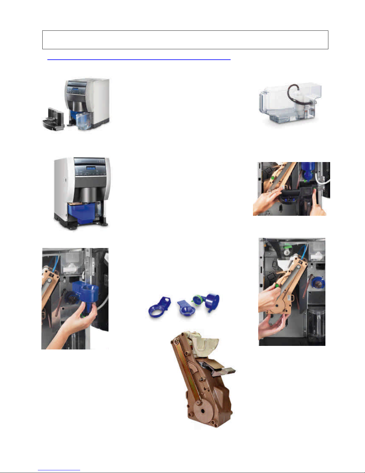
Daily Cleaning And Hygiene - espresso Version
(Expected time 6 minutes)
Remove the dispensing compartment and the tray,
slide out the internal tank. Clean and rinse the
components thoroughly under current water, empty
and rinse the tank (FIG. 1 – FIG. 2)
Remove the coffee grounds container, empty it and
rinse it thoroughly (FIG. 3)
Remove the drip tray located under the mixer, rinse
it and eliminate any residue (FIG. 4)
Slide out the external mixer assembly and
disassemble it (FIG. 5 – 6 ), clean and rinse out
thoroughly all residue.
Remove the brewer unit, clean and rinse with hot
water (FIG. 7 – 8).
Reassemble all parts, taking care not to touch with
your hands any parts that come into contact with
food.
Carry out a mixer automatic wash cycle according to
the pre-set procedures.
Close the door and make some test selections.
NB: In order to speed up the operations, it is
advisable to replace with components that were
already cleaned and sanitised at the workshop, and
take to the workshop the dirty components for
cleaning and sanitising. The cleaning and hygiene
operations must be carried out the evening, after the
machine use, or the next morning before starting to
use the machine.
Fig. 1
30
–
DAILY CLEANING AND HYGIENE PROGRAM
Fig. 2
Fig. 3
Fig. 4
Fig. 7 Fig. 8
Fig. 5
Fig. 6
Page 41
NW Global Vending – TECHNICAL MANUAL
This document was produced by MARK AC for the exclusive use of the technical personnel in the after-sales service.
. No part of this document may be divulged to a third party or reproduced partially or entirely without the prior permission of NW GLOBAL VENDING
. All rights reserved.
New dispenser “KORO” 07/10/2005 page 41 / 42
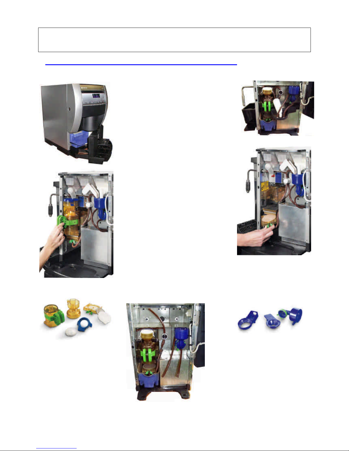
Daily Cleaning And Hygiene - Fresh brewer Version
( Expected time 6 minutes)
Remove the dispensing compartment and
the tray, slide out the external tank. Clean
and rinse the components thoroughly under
current water, empty and rinse the tank
(FIG. 1)
Remove the coffee grounds container, empty
it and rinse it thoroughly
(FIG. 2)
Remove the brewing chamber and
disassemble it, clean and rinse under hot
current water (FIG. 3 – 5)
Remove the lower filter-holder, clean and
rinse thoroughly (FIG. 4)
Remove the spouts assembly and the support
tray, clean and rinse thoroughly (FIG 7).
Slide out the external mixer assembly and
disassemble it (FIG. 6 ), clean and rinse out
thoroughly all residue.
Reassemble all parts, taking care not to touch
with your hands any parts that come into
contact with food.
Carry out a mixer automatic wash cycle
according to the pre-set procedures.
Close the door and make some test
selections.
Fig. 4
Fig. 6
Fig. 3
31 – DAILY CLEANING AND HYGIENE PROGRAM
FRESH BREWER UNIT
Fig. 1
Fig. 2
Fig. 5
Fig. 7
Page 42
NW Global Vending – TECHNICAL MANUAL
This document was produced by MARK AC for the exclusive use of the technical personnel in the after-sales service.
. No part of this document may be divulged to a third party or reproduced partially or entirely without the prior permission of NW GLOBAL VENDING
. All rights reserved.
New dispenser “KORO” 07/10/2005 page 42 / 42
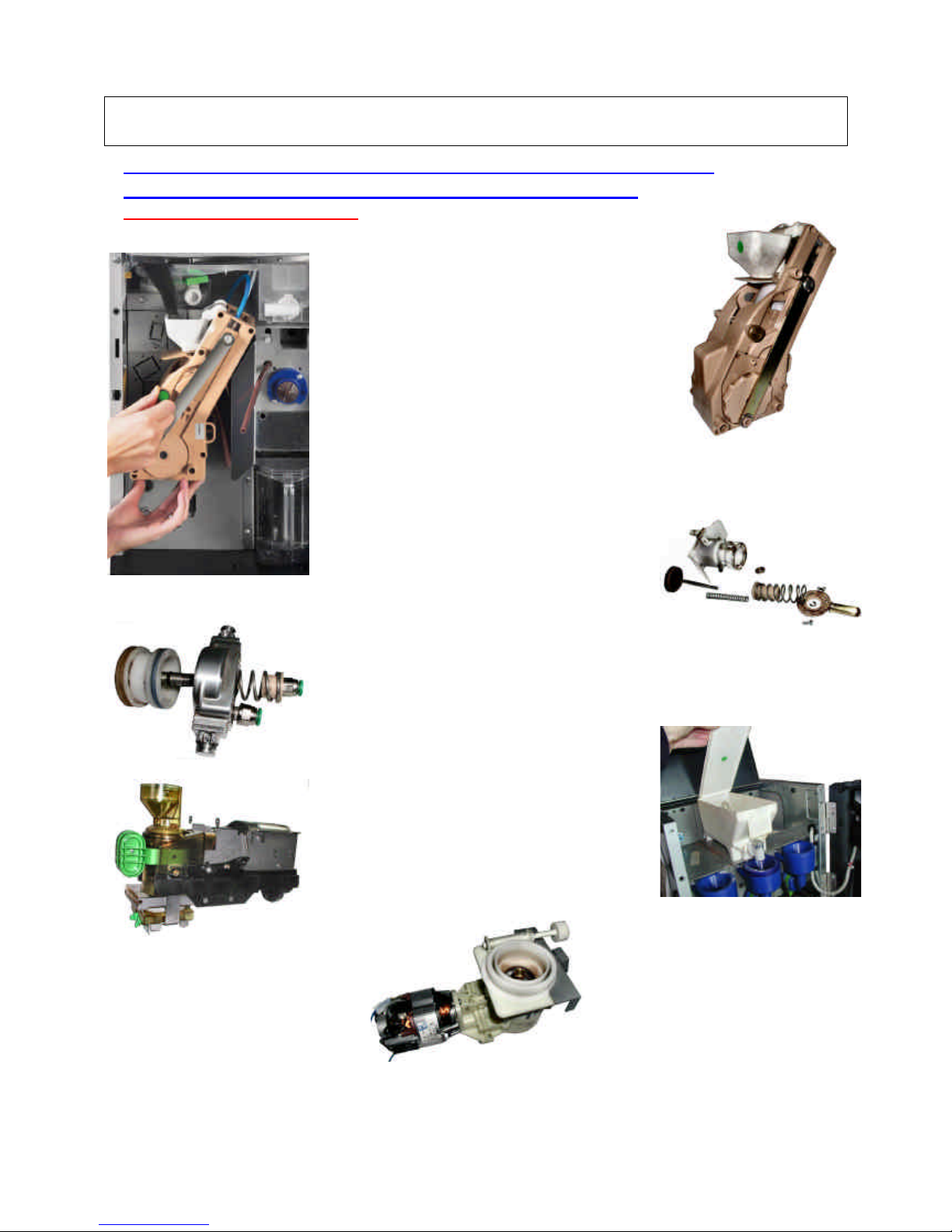
Monthly Cleaning And Hygiene (or every 5000 selections)
For all versions: Espresso - Fresh Brewer - Instant
Expected time 18 minutes
ONCE A MONTH, OR EVERY 5000 SELECTIONS, THE
FOLLOWING SCHEDULED MAINTENANCE OPERATIONS
MUST BE CARRIED OUT; AS USUAL IT IS ADVISABLE TO
CARRY OUT SUCH OPERATIONS AT THE WORKSHOP, AND
ON SITE SIMPLY REPLACE THE UNITS WITH THE ONES
WHICH WERE ALREADY SUBJECTED TO SCHEDULED
MAINTENANCE.
Remove the “Z3000’ unit from the vending machine
(FIG. 1 – FIG. 2); disassemble the unit completely,
remove the upper piston and the lower brewing
chamber (FIG. 3 – FIG. 4); carry out the
maintenance operations indicated in the specific
manual, and more specifically, clean or replace the
filters and lubricate the seals.
Remove the “SIGMA BREWER” unit from the
machine; clean thoroughly (see specific manual),
more specifically the brewing chamber and the lower
filter; check the efficiency of the mechanism and of
the position micro-switches.
If the filter is clogged for more than 50% must be
replaced (FIG. 5)
Remove the powder containers, empty and clean
them thoroughly in the inside, especially the ports
and the auger (FIG. 6)
Remove the grinder and doser assembly, empty any
coffee residue, check the state of the grinding
wheels, check the efficiency of the sensor that
detects the number of revolutions (FIG. 7)
Reset the correct distance between the grinding
wheels (see specific manual).
Reassemble all parts, taking care not to touch any
parts that come into contact with food.
FIG. 1
FIG. 6
32
–
MONTHLY CLEANING AND HYGIENE PROGRAM
FIG. 3
FIG. 2
FIG. 4
FIG. 5
FIG. 7
 Loading...