

Necchi Supernova Instructions Manual

Instructions
1
Copyright -2004
For
Servicing
The Necchi
Supernova
Sewing
Machine

ANALYTICAL INDEX
2
Copyright -2004
Pages
INSTRUCTIONS TO BE GIVEN TO THE CUSTOMER .
1
- Using the correct needle 1
- Correct threading of the SUPERNOVA when using
One needle 2
- Threading of the SUPERNOVA when using two needLes (twin needle) 3
- To disconnect the " Automatic " 4
- Changing from Automatic to Straight Sewing . . . 5
- Cleaning of shuttle race and feed dog . . . . 5
- Adjusting the Thread Tensions 8
- Cleaning 10
- Lubrication 11
ADJUSTING THE MOVEMENTS OF THE VARIOUS
GROUPS OF PARTS IN RELATION TO EACH OTHER
(TIMING THE MACHINE) 12
- Timing of shuttle and needle bar in the SUPERNOVA 13
- Timing of feed dog and needle bar 26
Timing the regulating shaft of the stitch length regulating knob (Fig. 35) 29
- Timing of the Automatic Control Eccentric A 85241
( F i g . 3 9 ) . . . 36
- Timing of the zig-zag movement and the movement
Of the needle bar 38
HOW TO DISMANTLE THE UPPER GROUP OF THE
ZIG-ZAG MECHANISM (Figs. 46 and 47) 43
HOW TO ASSEMBLE THE UPPER GROUP OF THE ZIG
ZAG MECHANISM (Fig. 46) 46

Pages
3
Copyright -2004
IMPORTANT ADJUSTMENTS TO BE MADE AFTER THE
REASSEMBLY OF THE UPPER GROUP OF THE ZIG
ZAG MECHANISM 50
MINOR ADJUSTMENTS IN THE UPPER GROUP OF THE
ZIG-ZAG MECHANISM 51
THE F E ED DOG 54
- Adjustment of any Looseness in the Feeding Mechanism 55
- Adjusting the Height of Teeth of the Feed Dog above
the Needle Plate 55
- Alignment of Feed Dog in relation to the slots in the
Needle Plate 58
- How to check the alignment between the underside
of the presser foot and the teeth of the feed dog . . 60
5 - Minor adjustments of the Feed Dog 62
HOW TO CONTROL THE PRESSURE OF THE PRESSER
FOOT 62
- Positioning of presser bar and presser foot . . . 63
- Height of Presser Foot 64
UPPER THREAD TENSION 66
- The T hread Take-Up Spring (Check Spring) of the
Upper Tension 67
- Positioning of the Tension Mechanism in relation to
the Hole in the Arm 69
- Tension of the lower Thread (tension of the Bobbin
Case) 70
THE OSCILLATING SHUTTLE 71
TO REMOVE THE FEED ECCENTRIC CONNECT ING ROD
N° D 85506 AND THE CONNECT ING RODS OF THE
STITCH LENGTH REGULATION MECHANISM
(Figs. 74 and 75) 74

Pages
4
Copyright -2004
HOW TO REMOVE THE STITCH LENGTH REGULATING KNOB
AND THE REGULATING SHAFT (Fig. 75) . . . 76
HOW TO REASSEMBLE THE STITCH LENGTH REGULATING
KNOB AND THE REGULATING SHAFT . . . 76
H O W T O R EA S SEM B LE T H E F EE D EC C EN T RI C ROD N "
D 85506 AND T HE CONNECTING RODS OF THE STITCH
LENGTH REGULAT I N G M E C H A N I S M
((Fig. 74 and 75) 79
- General Rules with Reference to important Adjustments
of Stitch Length Regulating Knob and Regulating Shaft 80
- Adjustment of the Friction of the Stitch Length Re-
gulating Knob . . . . . . . . 81
3 - Zero Position of the Stitch Length Regulating Knob 82
ADJUSTMENT OF THE FEED DOG DISENGAGING ME
CHANISM (See figs. 79 and 80) 83
ADJUSTMENT OF THE ECCENTRIC N° 85663 ON THE NEEDLE
POSITIONING LEVER N° C 85662 (Fig. 81) . . 86
ADJUSTMENT OF THE AXIAL PLAY (END PLAY) OF
THE UPPER SHAFT 87
ADJUSTMENT OF THE CONTACT FINGERS N° A 26/1/23
AND N° A 26/1/13 WHICH REGULATE THE POSITION
OF THE NEEDLE AND THAT OF THE ZIG-ZAG WIDTH
REGULATING LEVER 89
ADJUS T MENT OF T HE FEED REGULATI NG ROD
(W HICH REGULATES THE "AUTOMATIC " LEN GTH
OF THE STITCH N" A 26/3/21 92
L
Some Troubles and their Remedies..... 95
ADJUSTMENT OF THE NUMBER OF IMPULSES FOR
EACH TURN OF THE CAM AXLE 96
How to count the Number of Impulses of th e Cam
Axle 98

Pages
5
Copyright -2004
ASSEMBLING THE PARTS UNDERNEATH THE MOUNT
ING PLATE N" C (A 26/1/1) OF THE AUTOMATIC DE
VICE (Fig. 93) 100
- Preparation of assembling the group as shown in fig. 94 101
- Preassembling of group Fig. 95 102
How to adjust the group of Fig. 95 in the mounting
Plate N° C (A 26/1/1) for the Automatic Device (see
Fig. 98) 104
TAKING CARE OF THE SEW ING MACHINE MOTOR .
108
A - Motor does not run at all or runs only sluggishly • . 108
B - How to replace the motor brushes 109
C - Motor turns tightly I l l
D - Motor runs but does not pull machine . . . 112
E - Motor is weak 112
F - Motor gets too hot 112
G - Motor smokes or emits a burning smell. . . . 113
H - Motor runs noisily or growls. Rattling noise during
Sewing 113

FOREWORD
6
Copyright -2004
This service manual shall be used together with the instruction
book for the SUPERNOVA Sewing Machine and with the parts
catalogue for this machine.
The maintenance of the SUPERNOVA Sewing Machine requires
no special skill or knowledge. All that is needed is a certain
mechanical aptitude and the availability of the necessary tools.
This manual is intended only for those mechanics that make
routine repairs and replace single defective parts. Major repairs
should not be carried out by persons of limited experience.
Therefore, if major repairs are required, it is suggested that the
complete head be returned to the distributor, after prior
authorization has been received from that distributor.
The SUPERNOVA Sewing Machine, like practically all sewing machines designed for household use, works on the principle of the
Lockstitch. This type of stitch is obtained by interlocking the
upper and lower thread inside the fabric, while the needle, going
down to its lowest position, penetrates the fabric and rises again
to its highest position. The two threads of the seam are thus
tightly interlocked at every stitch, adhere closely to the fabric
and hold the plies of the fabric firmly together. If either of the two
threads breaks, or if the threads are cut off after the sewing
operation is completed, the seam will not unravel, but only two
or three stitches may get loose and open up. The illustrations
Figures " a " to " d " indicate the formation of a single lockstitch
and the interlocking of both threads in the fabric.
All machines consist of two major portions, the arm and the bed.
Arm and bed are firmly held together by means of screws and
pins. In the horizontal portion of the arm is inserted the arm
shaft (upper

Shaft) which obtains its rotary movement from the revolving
7
Copyright -2004
balance wheel. The balance wheel, which is securely fastened
to the right hand end of the arm shaft, is driven by a belt from an
electric motor. The various movable parts of the sewing machine
obtain their respective movements from the rotary of the arm shaft
with the aid of connecting rods, cranks, levers etc. . . . Below the
bed of the machine is mounted the oscillating shaft (driver shaft),
to the left end of which is firmly attached the shuttle carrier. By
means of a crank connecting rod, and oscillating rock shaft, a
slide block and a shaft crank, the rotary movement of the arm
shaft is transformed into the oscillating movement of the carrier
shaft. The shuttle carrier, in turn, imparts the oscillating
movement to the oscillating shuttle which moves back and forth
inside of the shuttle race. The forward and backward, as well as
the up and down movements of the feed dog, are also obtained
from the rotary movement of the arm shaft by means of connecting rods, rock shafts and a feed bar below the bed of the machine.
The up and down movement of the needle bar, as well as that of
the thread take-up lever, is also derived from the rotary
movement of the arm shaft by means of cranks and a
connecting link.
The bobbin case is placed on the post inside the oscillating
shuttle and then pressed into the oscillating shuttle. The
oscillating shuttle, after its point has entered the loop of the
needle thread, makes a partial revolution, just sufficient to carry
the enlarged loop of the needle thread over and around the
bobbin case and then lets it slide off easily from the oscillating
shuttle. After the rising thread take-up lever has pulled the
needle thread away from the oscillating shuttle, the shuttle
returns to its starting position. This oscillating movement of the
shuttle is repeated at every stitch.
To the arm of the machine are also attached the tension
mechanism for the needle thread (upper tension), and the
various thread guides which lead the thread from the spool to
the needle.
In the upper portion of the arm, the Automatic Device is installed,
consisting of a mounting plate on which the cam-carrying
bushing and the other component parts are assembled. The
Automatic mechanism is driven by a suitable cam mounted on
the upper shaft. The SUPERNOVA machine is provided with a
built-in motor inside the arm, as well as a transformer which
feeds the sewing light at 12 V and the motor at two different
voltages giving two different speeds.

Tools and necessary accessories
8
Copyright -2004
To service and repair any type of sewing machine efficiently, the
mechanic should have available proper tools and several
accessories, essential for a good maintenance job. He must
know how to operate the machine and be familiar with the various
mechanisms of the machine and the manner in which they are
adjusted (timed). Finally, he must be scrupulous about cleaning
the machine and oiling all the parts which require lubrication.
For the mechanics we have available a tool kit containing all
wrenches screw drivers and gauges for any repair and timing of
the SUPERNOVA machine.
Suggestions for the mechanics
After a short examination of the machine, a good mechanic will
be able to state with certainty whether the machine sews correctly
or not and, consequently, whether repairs are required. Many
times a customer calls in a mechanic to have a machine repaired
which supposedly is out of order. Quite often the customer
attributes the poor performance of the machine to imaginary
defects of some of the sewing machine parts, while in reality the
trouble lies in the customer's own lack of experience in using the
machine.
There are four fundamental questions every mechanic should ask
in investigating the customer's knowledge with regard to the
machine:
Does the customer know what type and size of needle to use
and
how to insert the needle in the machine?
Does the customer know how to thread the machine correctly?
Does the customer know how to clean the shuttle race?
Does the customer kn ow how to judge the tensions of upp er
and lower thread and how to adjust these tensions, if
necessary?
INSTRUCTIONS TO BE GIVEN TO THE CUSTOMER
9
Copyright -2004
Using the correct needle.
The needle must be selected in accordance with the type of
material to be sewn, the kind of work to be performed and the
thickness of the thread to be used (see « Needle and Thread
Chart » in Instruction Booklet).
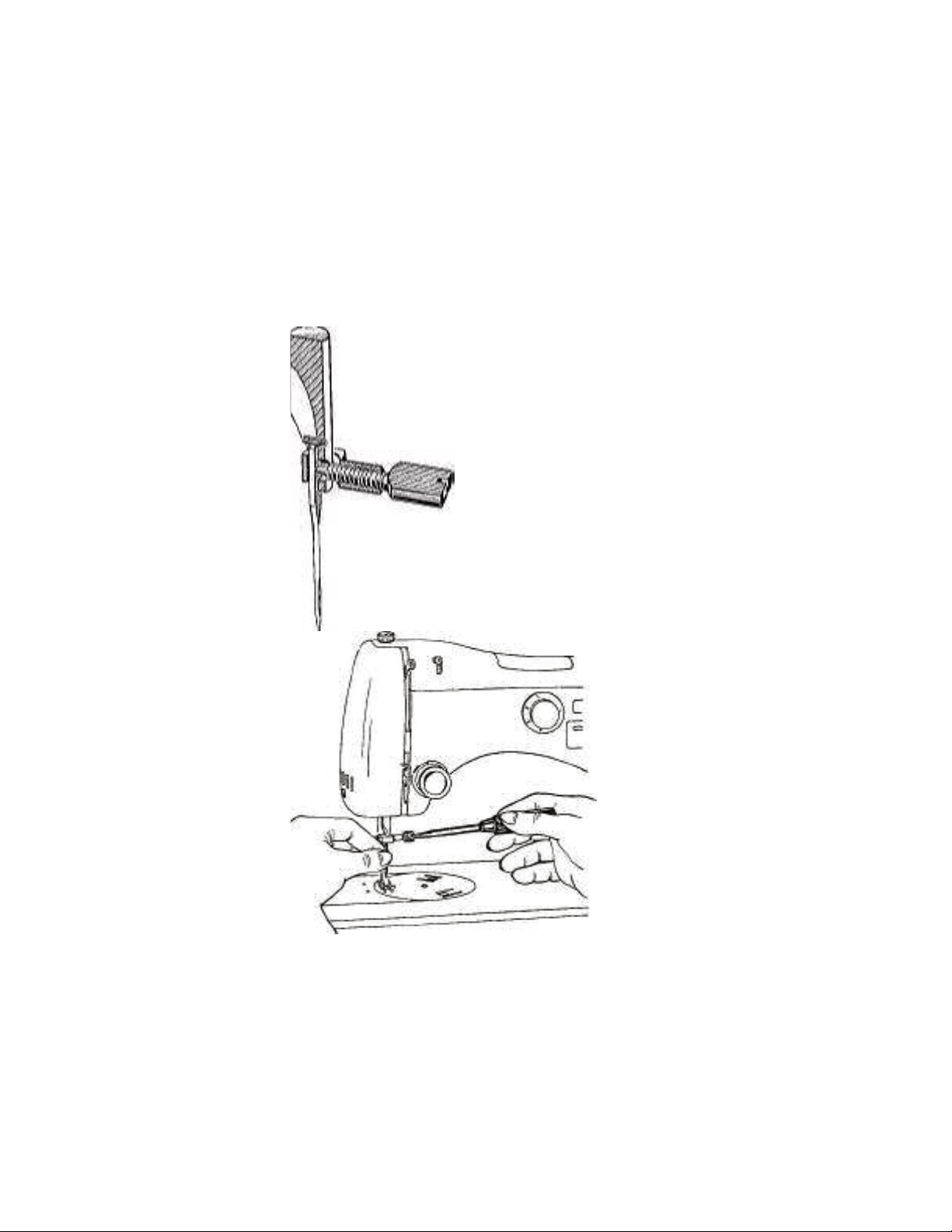
To insert the needle, proceed as follows:
Turn the balance wheel by hand toward you until the needle bar
reaches its highest position, then insert the needle so that the flat
portion
Fig. 1 Fig. 2
of its shank faces the groove in the needle bar. Push the needle
up into the needle bar as far as it will go, then firmly tighten the
screw in the needle clamp so that the needle is held securely in
the needle
bar (see Figs. 1 and 2).
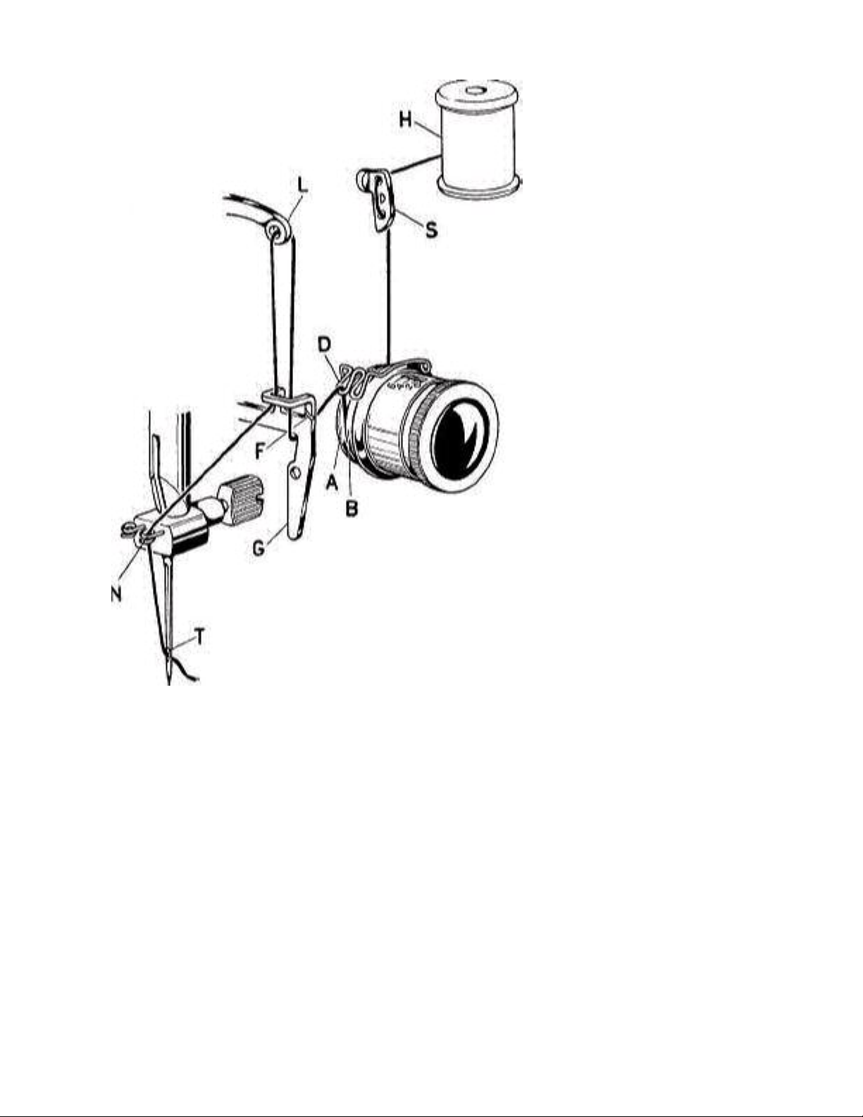
Correct threading of the SUPERNOVA when using one needle.
10
Copyright -2004
Proceed as follows:
Fig. 3
Bring the needle to its highest position by tiring the balance
wheel towards you.

Place spool of thread “H " on spool pin and draw thread through
11
Copyright -2004
thread guide " S ", as shown in Fig. 3.
Pull thread downward, then insert it from right to left between
both tension discs and bring it upward again over the check
spring
" D” (Fig. 3).
Bring the thread downward under the thread guide tension
arm
" G ", pass it through the slot " F” and then upward through the
guide hook " K ".
Pull the thread upward and pass it, from right to left, through the
eyelet " L " of the thread take-up lever.
Draw the thread downward, passing again through the slot " F
"
and into the guide hook " K ".
Pull the thread downward and, by means of a twisting motion,
bring it into the thread guide " N " on the needle clamp.
h) Finally, guide the thread, from left to right, through the eye of
the needle “T ", pull the thread through the needle eye, leaving
about four inches of free thread hanging down from the needle.
Threading of the SUPERNOVA when using two needles (twin
needle).
The threading of the SUPERNOVA with double needle is
illustrated in Fig. 4.
The unwinding of the thread from the two spools must take place
as shown in Fig. 4 to keep the two threads separated.
The two threads must pass separately through the upper and
the
lower holes of the thread guide " S ".
To keep the two threads separated, pass one thread between
the
tension discs " A " and " B ", and the other one between the ten-
sion discs " B " and " C ". The thread, running between the ten-
sion discs " A " and " B ", must pass through the loop " D " of the
check-spring, whereas the other thread must pass through
the
loop " E " of the same spring.
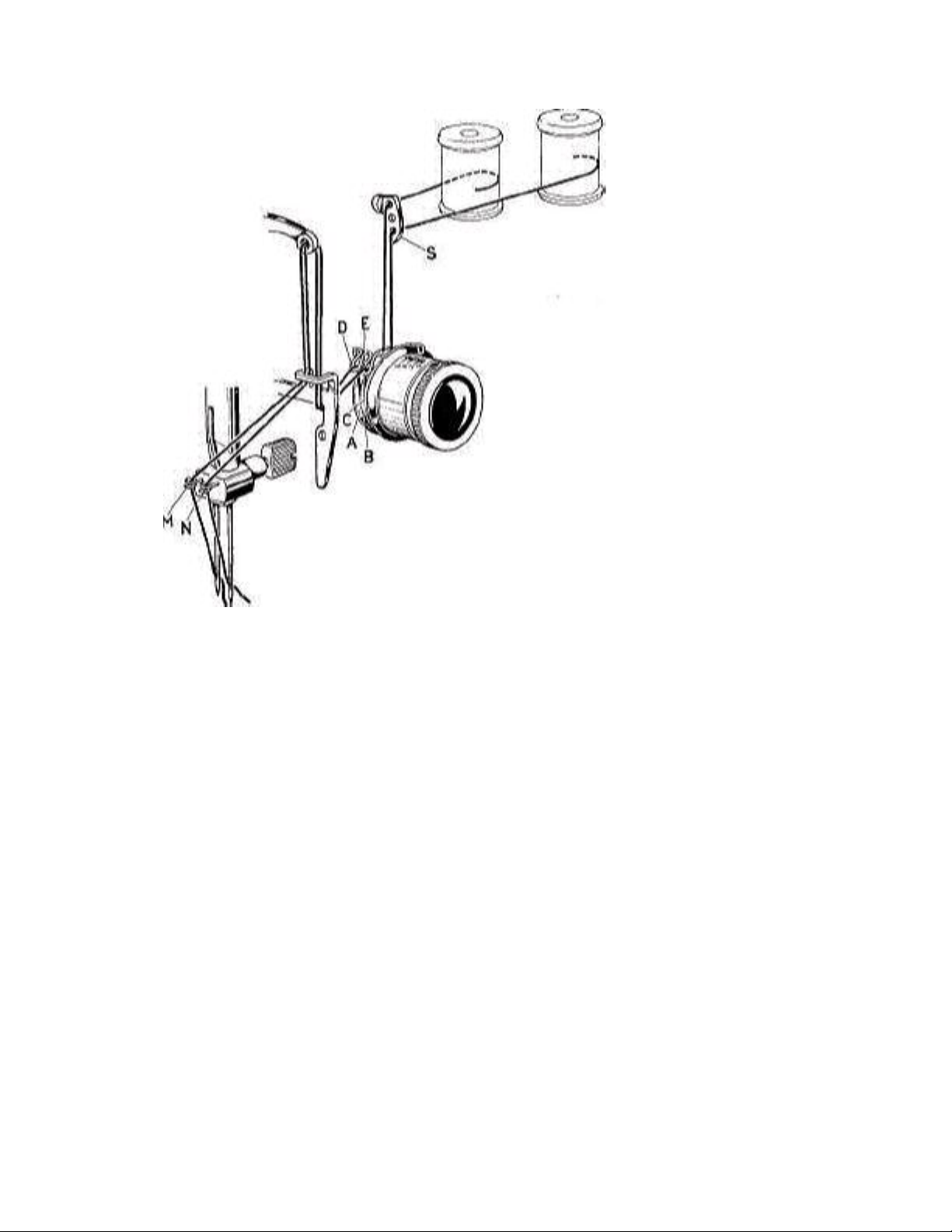
The two threads must be inserted separately, one in each of
12
Copyright -2004
the two thread guides " M " and " N " on the needle clamp.
Fig. 4
To disconnect the “Automatic"'.
This operation has to be done when the machine is at a
standstill.
Turn the design regulating knob clockwise until the square mark
(*) is in line with the mark above this knob.
Turn the balance wheel for one full turn, toward you.
Turn the design regulating knob clockwise again, until the triangle
sign and the mark above the knob are in line (Stop).
The “Automatic " is now completely disconnected.

Changing from automatic sewing to straight sewing.
13
Copyright -2004
Disconnect the "Automatic" as already explained on page 4.
Remove the cams from the machine by proceeding as follows:
Swing the Cam Disengaging Lever (at the rear of the arm)
entirely to the left as far as it will go.
Open the small cover on top of the arm and take out the cams.
Close small cover again.
Swing back the Cam Disengaging Lever entirely to the right as
far as it will go.
The machine is now ready for straight sewing.
Fig. 5 Fig. 6
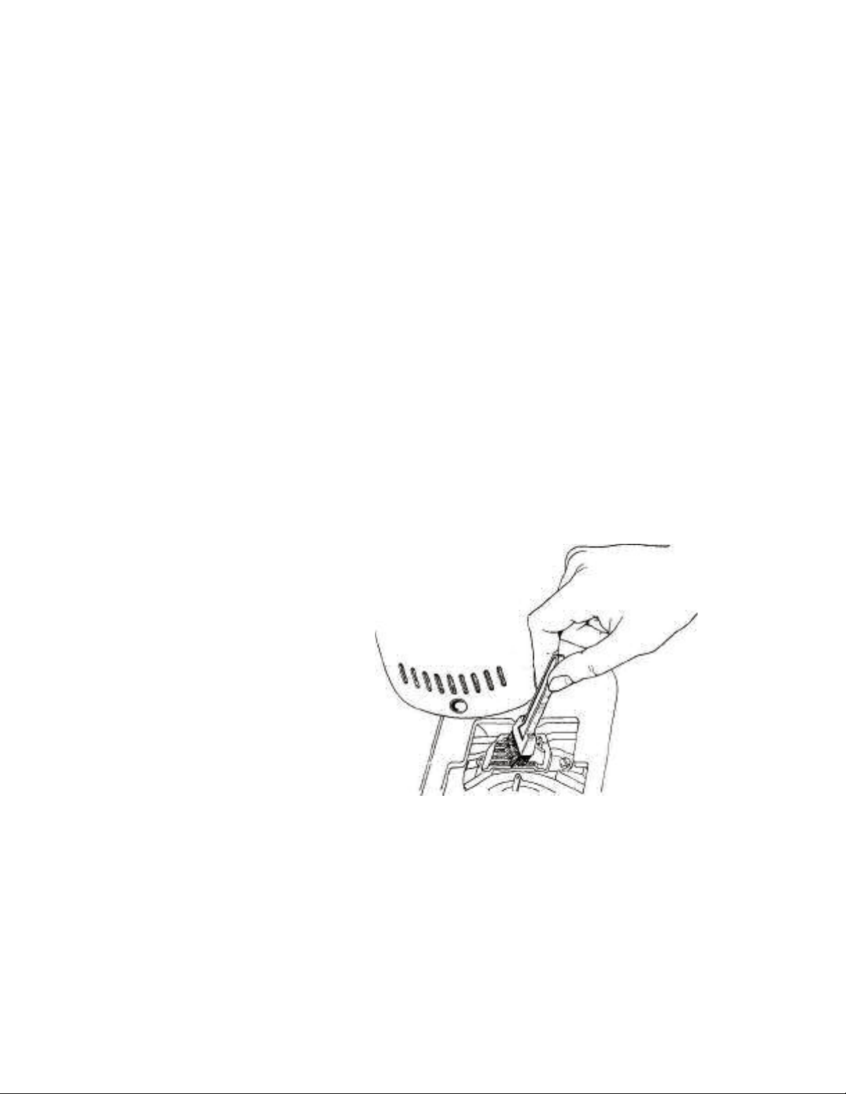
Cleaning of shuttle race and feed dog.
Bring the needle up to its highest position by turning the balance
Wheel toward you. Move slide plate to extreme left. h) Tilt the
machine back on its hinges, so that the underside is in
Full view. c) Rotate the needle plate release lever (Fig. 6) in the
direction of
Arrow “C “until the center stud in the needle plate becomes free,
Then remove the needle plate.
Note: To fasten the needle plate after having placed it in its re-
14
Copyright -2004
ceptacle, push the lever shown in Fig. 6 in the direction of the
arrow “A " and, at the same time, rotate it in the direction of the
arrow " B ".
Clean teeth of feed dog with a small brush (Fig. 7). Clean also
underside of needle plate around vicinity of feed dog.
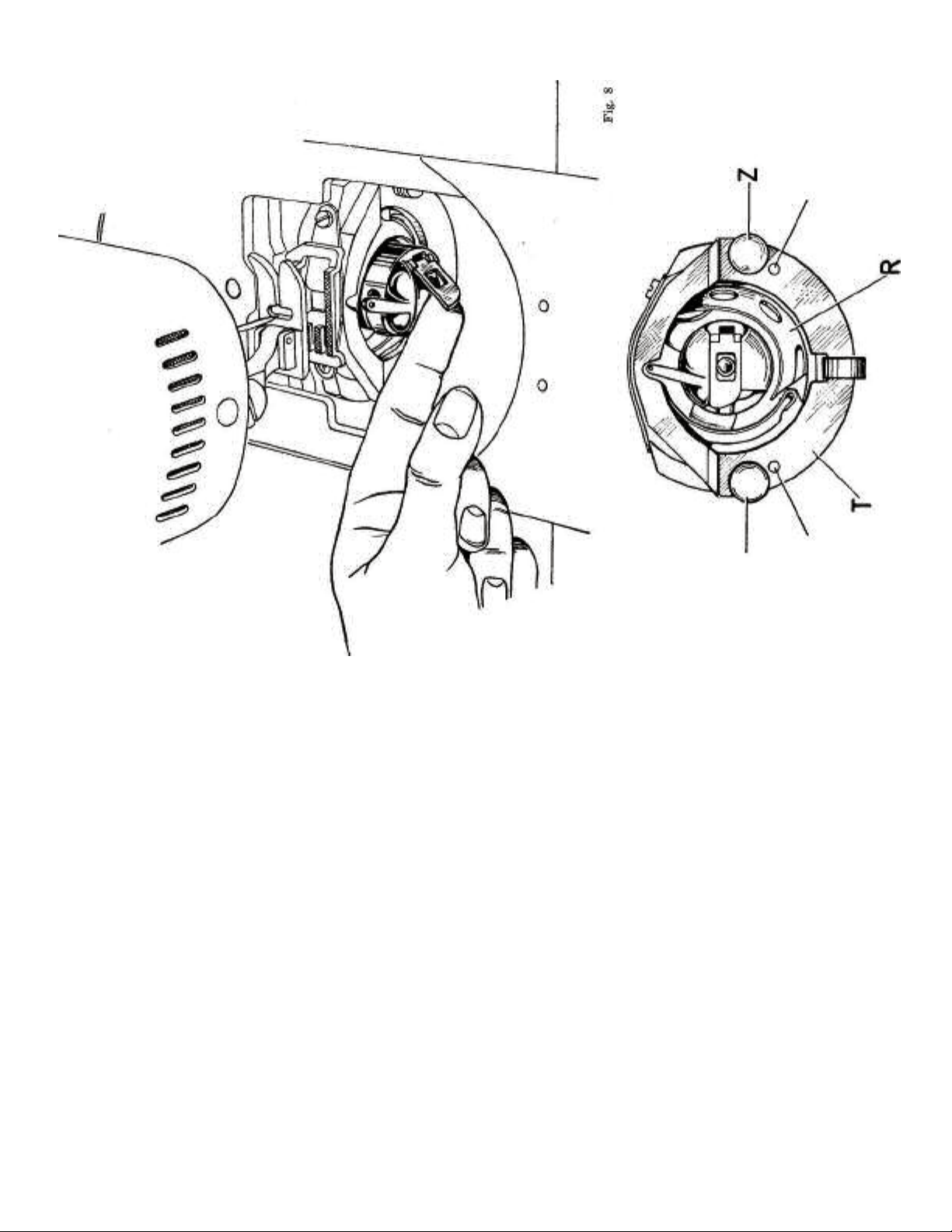
Lift latch of bobbin case with thumb and forefinger of left hand
(Fig. 8), and remove bobbin case by pulling it toward the left and
out of the machine.
/) Snap out pins " Z " (Fig. 9) by swinging them sideways, and,
with
left hand, remove the race cover plate " T " by turning it away
From the race. g) Remove shuttle (hook) "R" by gripping its
center stud with thumb
and forefinger of left hand and pulling it to the left and out of the
Machine. This leaves the shuttle race free for cleaning. h)
Remove lin t and pieces of thread with a piece of rag, or brush
With a small brush. Put a drop of oil into the race and oil rim only
Of shuttle (hook). i) To replace shuttle (hook), insert it into the
race with thumb and
Forefinger of left hand, fitting it into place opposite the shuttle
Fig. 7
Carrier without using force (Fig. 10). k) Place the race cover
plate “T " onto the two small studs " G "
15
Copyright -2004
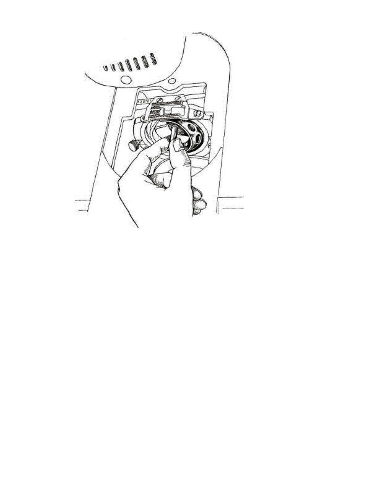
Fig. 10
16
Copyright -2004
and snap pins " Z " back into place (Fig. 9).
Insert bobbin case, replace needle plate (as shown in Figs. 5
and 6) and lower the machine to its working position.
Adjusting the thread tensions.
The tensions of upper and lower thread are correctly balanced if
both threads interlock in the center of the fabric, as shown in
Fig. 12.
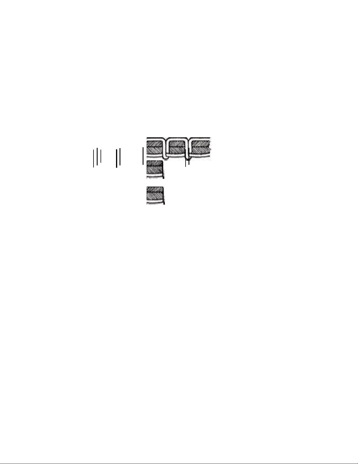
If the tension of the upper thread is too strong in relation to that
of the lower thread, the lower thread will be pulled up to the top
surface of the fabric and appear there in the form of small knots or
loops (see Fig. 13).
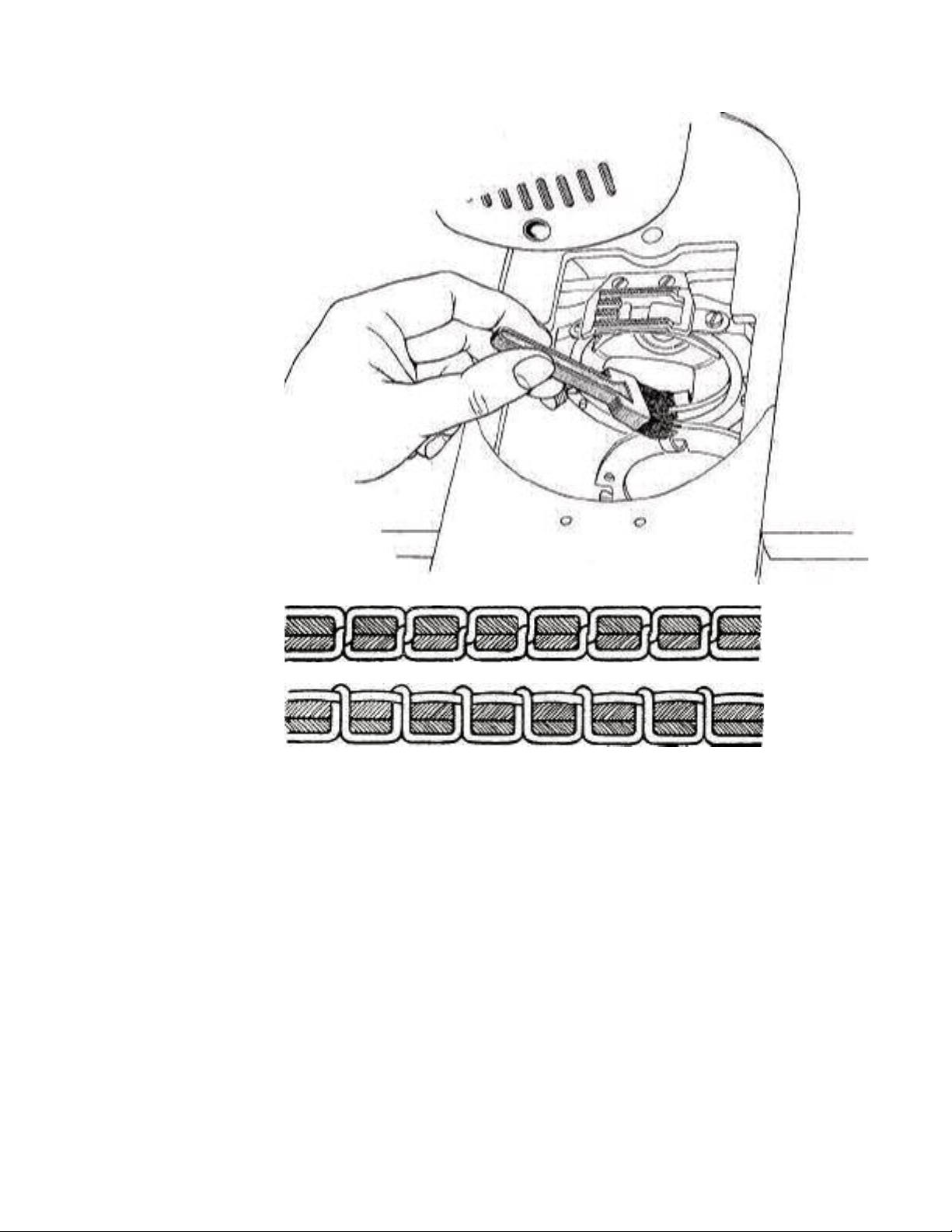
Fig. 11
17
Copyright -2004
Fig. 12
Fig. 13
To correct this condition, make certain that the presser foot is
18
Copyright -2004
down, then turn Tension Regulating Knob to the left.
If tension of needle thread is too loose, or tension of bobbin
thread is too tight, bobbin thread will lie straight along underside
of fabric and needle thread will be pulled down to underside,
being visible there in, the form of loops or small knots (Fig. 14). To
correct this condition, make certain that the presser foot is down,
then turn Regulating Knob to the right.
Make several stitches to check whether needle thread tension is
correct, and, if necessary, adjust further by turning Regulating
Knob.
mm.
Fig. 14
Cleaning.
To clean the machine, prepare a mixture of 90 % kerosene and 10
% lubrication oil. Fill an oil can with the cleaning fluid, and also
pour a sufficient quantity of this liquid into a pan.
If the machine, due do dirt and gummed oil, runs heavily, force
with the oil can, plenty of the cleaning fluid into all oil holes and on
to all movable parts. Then run the machine at high speed until all
dirt and hardened oil is washed out.
Should some parts of the various mechanisms of the machine
have become badly clogged with dirt and gummed oil, remove
these parts from the machine and place them for a while in the
pan filled with cleaning fluid. After the dirt and gummed oil have
become loose, clean the parts with a small brush dipped in the
cleaning fluid. Then wipe them dry with a soft clean rag.
The electric motor must always be kept dry. Only the motor shaft
requires a few drops of oil from time to time.
Lubrication.
19
Copyright -2004
After the machine has been wiped clean with a rag, apply a drop
of good oil to every movable part, to the bearings of the lower
shaft (to which the shuttle carrier is attached) and to all other
shaft bearings of the machine. The various oil holes in the
machine indicate where the oil must be applied.
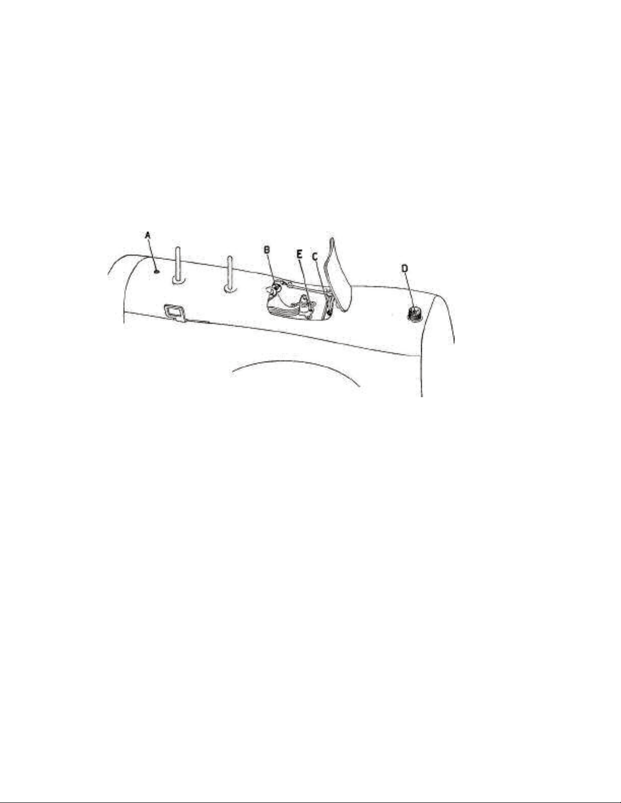
Apply 20 to 30 drops of oil into hole " A " (on top cover, Fig. 15).
Open the small cover and apply one or two drops of oil to the
vertical gear indicated at " B " in Fig. 15. Apply also a drop of oil to
the point indicated by " C " in Fig. 15. Finally, after having
taken out the cams, apply also one or two drops of oil to the point
indicated by " E " (Fig. 15).
Fig. 15
Use only Necchi oil.

ADJUSTING THE MOVEMENTS OF THE VARIOUS GROUPS
20
Copyright -2004
OF PARTS IN RELATION TO EACH OTHER
(TIMING THE MACHINE)
To obtain a continuous and satisfactory performance from the
machine, the movements of the various groups of parts in
relation to each other must be adjusted (timed) in such a manner
that the actions of these parts repeat themselves regularly at
certain fixed time intervals. In the following are explained the
most important timing procedures, omitting operations which are
solely performed on the assembly line in the factory where the
machines are made.
For each timing procedure is also mentioned the corresponding
timing gauge which should be part of the mechanic's equipment.
Furthermore, whenever possible, a general rule for the timing
procedure in question is given, in case the corresponding timing
gauge should not be available to the mechanic.
Timing, performed in accordance with the rules set down in the
following chapters, is indispensable when:
One or several elements of a group of parts have been
replaced
whose actions depend on those of another group of parts, or
when
entire groups of parts, depending on each other, must be
removed
and replaced.
It is necessary to check the proper function of a group of parts in
relation to another group of parts, the movements of these
groups
depending on each other.
Certain disturbances must be eliminated which interfere with the
proper progress of sewing.
The following five interdependent adjustments are essential:
The timing of the move ments of shuttle and needle bar.
The timin g o f the movements of feed dog and needle bar.

The timing of the movements of the zig-zag mechanism and the
21
Copyright -2004
needle bar.
The timing of the Stitch Regulating Worm.
The timing of the eccentric for the “Automatic ".
Note: All these timings have been done and thoroughly checked in
our factory during the assembly. We, therefore, can guarantee
their perfection.
In some cases, as for example the timing of shuttle and needle
bar, the parts are fixed together by pins and, therefore, the
timing will never change.
- Timing of shuttle and needle bar in the SUPERNOVA.
Adjustment - Height of the Needle Bar.
Turn the balance wheel by hand toward you until the point of the
shuttle is just at the center of the rising needle.
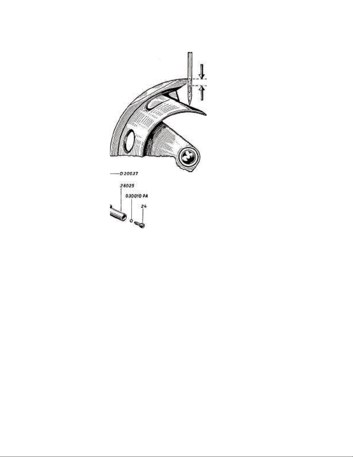
At this moment the point of the shuttle should be about 1/16"
above the upper part of the needle eye (Fig. 16).
If the distance " a " is more or less than 1/16", an adjustment is
necessary. Loosen slightly screw No. 24 (Fig. 17) in the needle
bar connecting stud No. 26025 so that the needle bar No. D
20037 is still held in position by friction.
Now, without turning the balance wheel, push the needle bar up
or down by hand until the distance " a " is equal to about 1/16".
Tighten screw No. 24 firmly after this adjustment.
This adjustment can also be achieved with the aid of the TIMING
GAUGE No. 10-5. The gauge is composed of a body, similar to the
shuttle, and of a false needle (gauge pin), contained in the
upright of
a - about
22
Copyright -2004
1/16"
Fig. 16
Fig. 17
the gauge so that it will not be misplaced. In the following, a
description of the use of this gauge is given:
Insertion of the TIMING GAUGE No. 10-5.
Turn the balance wheel by hand and bring the needle bar to its
highest position (Fig. 18).
Replace the normal needle of the needle bar with the false one
of
the gauge. The false needle is inserted in the same way as a
nor
mal one.
Remove the shuttle race cover plate No. 26333 and the
shuttle
No. 26327.
Insert the shuttle-shaped gauge into the shuttle race (Fig. 18).
False needle
23
Copyright -2004
Fig. 18
False
needle
Fig. 19
Timing procedure.
24
Copyright -2004
a
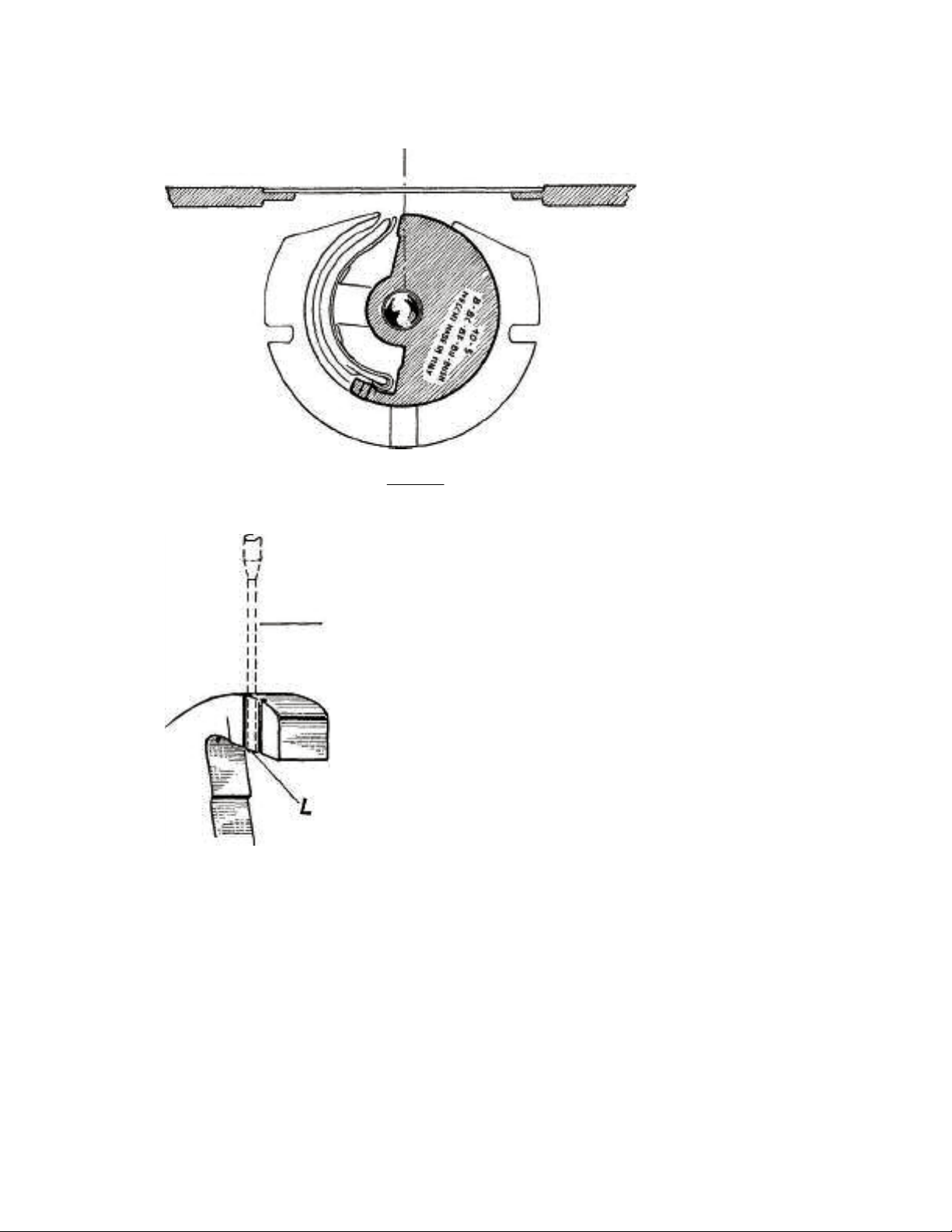
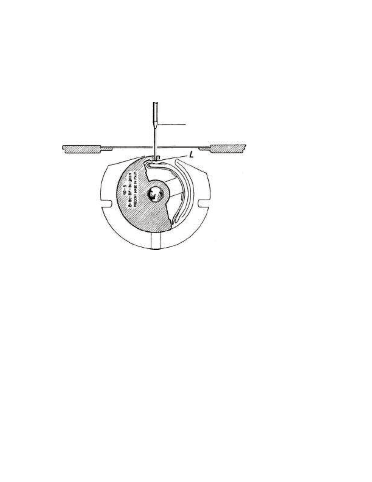
Bring the needle bar to its lowest position. In this position, the
lower end of false needle should be just in line with the lower
edge " L " of the prong of this gauge, as shown in Figs. 19 and 20.
If an adjustment of the height of the needle bar is necessary,
loosen slightly screw No. 4 (Fig. 17) so that the needle bar is still
held in position by friction. Then, without turning the balance
False needle
Fig. 20
wheel, move the needle bar up or down by hand until the condition, shown in Figs. 19 and 20, is met. Tighten screw No. 24 firmly.
Adjustment - Position of the needle eye in relation to the shuttle.
The needle bar must be lined up in such a way that the center
line of the needle eye is perpendicular to the shuttle (Fig. 21),
i.e. the needle eye must not be lined up obliquely in relation to
the shuttle (Fig. 21a). The correct alignment of the needle causes
the loop of the thread to be arranged in such a way that it can be
easily caught by
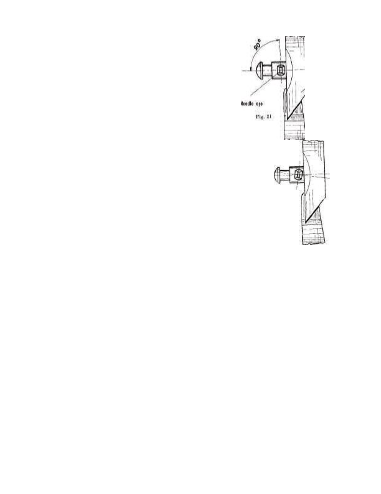
_ Point
25
Copyright -2004
of
sh uttle
Fig.
21-a
Needle eye in correct
position
The point of the shuttle. This is especially necessary when the
machine sews with two needles.
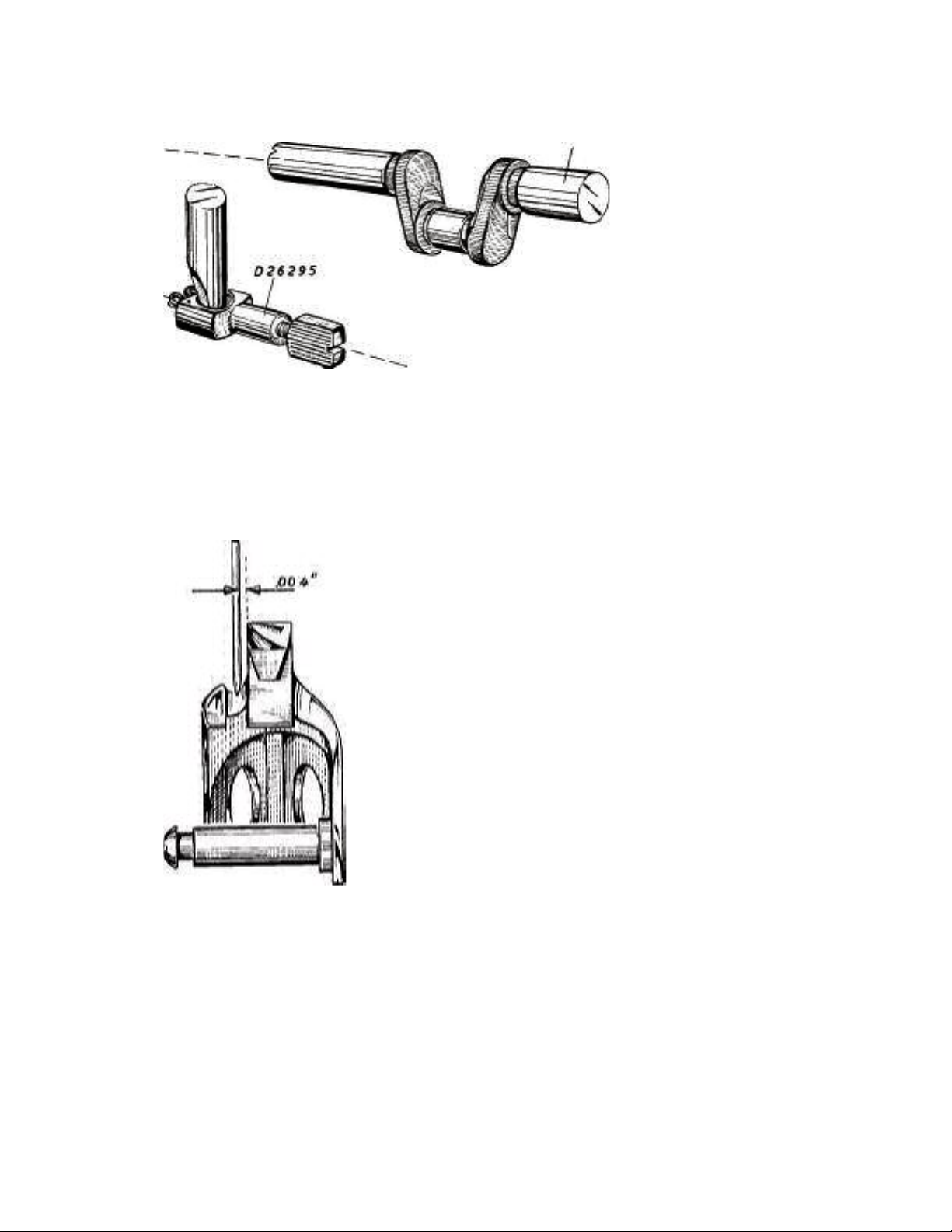
In order to obtain the above mentioned condition, it is necessary
that the needle bar clamp No. D 26295 (Fig. 22) be firmly
tightened and that axis " a " of the needle clamp No. D 26295 be
directed parallel to axis " b " of the upper shaft No. C 85201 (Fig.
22) or, what amounts to the same thing, that the axis " a " of the
needle bar clamp No. D 26295 is in the direction of the
longitudinal axis of the machine.
If it is necessary to make an adjustment, proceed as follows:
Loosen slightly screw No. 24 of the needle bar connecting
stud No. 26025 (Fig. 17).
Without moving it up or down, rotate the nee dle bar about its
own axis in the required direction until it is in the position shown
in Fig. 22.
Tighten screw No. 24 firmly.
HI. Adjustment - Distance between the needle and the shuttle.
Without touching the needle, the point of the shuttle should be
Needle eye in incorrect
position
C85201
26
Copyright -2004
Fig. 22
Fig. 23
is too far away from the needle, loosen the screw " F " (Fig. 24)
below the bed of the machine. Then, move the race body No. D
26330 with the carrier shaft No, C 26325 in (axial) direction
until the shuttle comes as close as possible to the needle without
touching it. Before tightening the screw " F ", adjustment IV
should be checked.
18
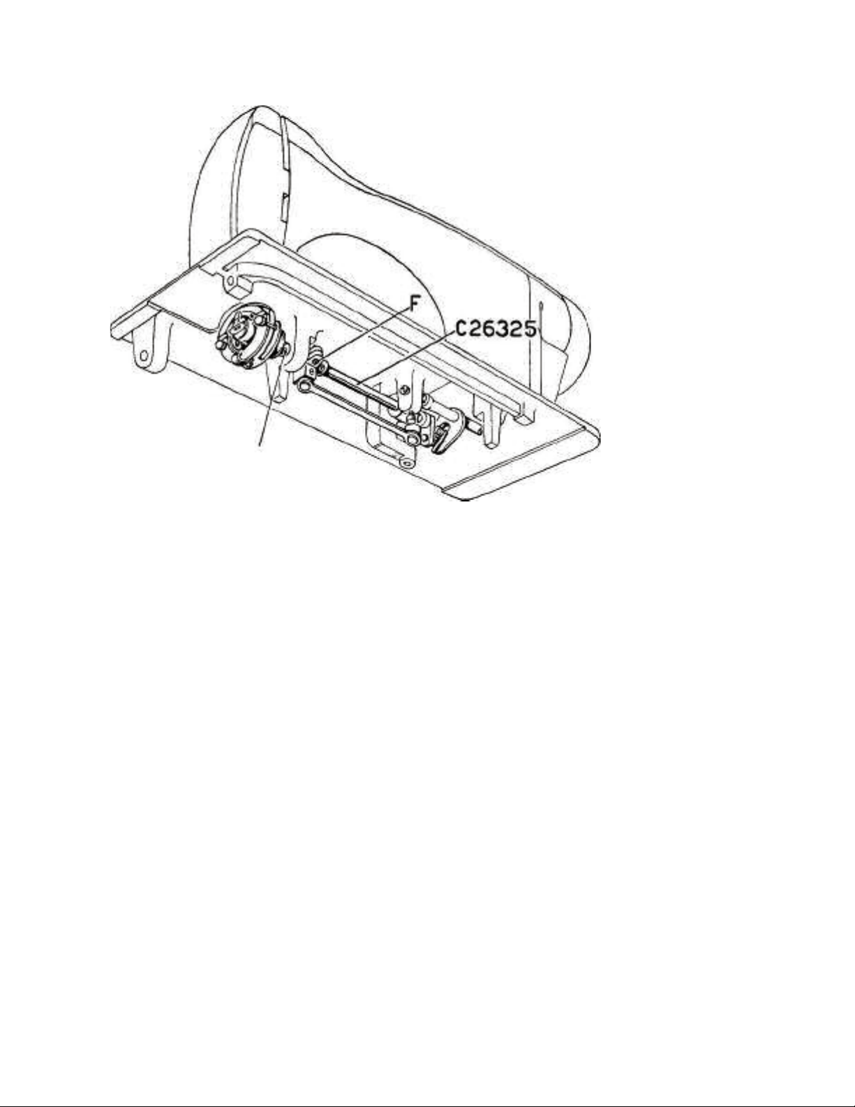
D26330
27
Copyright -2004
Fig. 24
Adjustment - Centering the needle in relation to the race cover
plate.
The single needle " A " (Fig. 25) should pass exactly through
the center of the slot in the shuttle race cap No. 21330. In the
twin-needle machine, the correct position of the needle is that
shown in Fig. 26. To perform this adjustment, rotate the race
body, No. D 26330, without moving it in an axial d irec tion ,
around t he ca rrie r sha ft No . C 26325. Now, the screw " F " can
be firmly tightened (Fig. 24). All four adjustments mentioned can
also be achieved with the aid of the TIMING GAUGE No. 10-9.
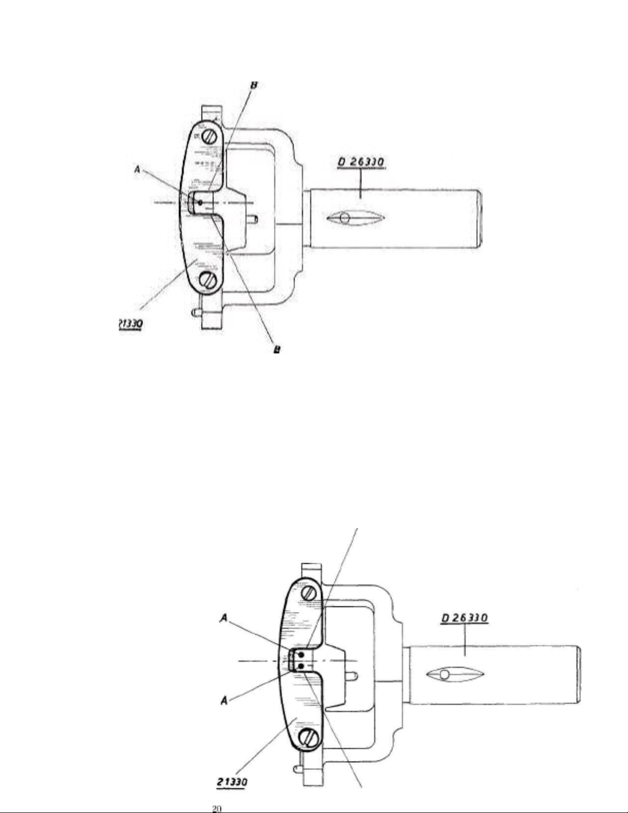
The n e edle "A " i s at equal d i s tance f r o m both e d g e s " B "
28
Copyright -2004
Fig. 25
Both
needles
"A" are
at equal
distanc
es fro m
the
ed g e s
" B "
Fig.
26
B
B
b)
29
Copyright -2004
c)
d)
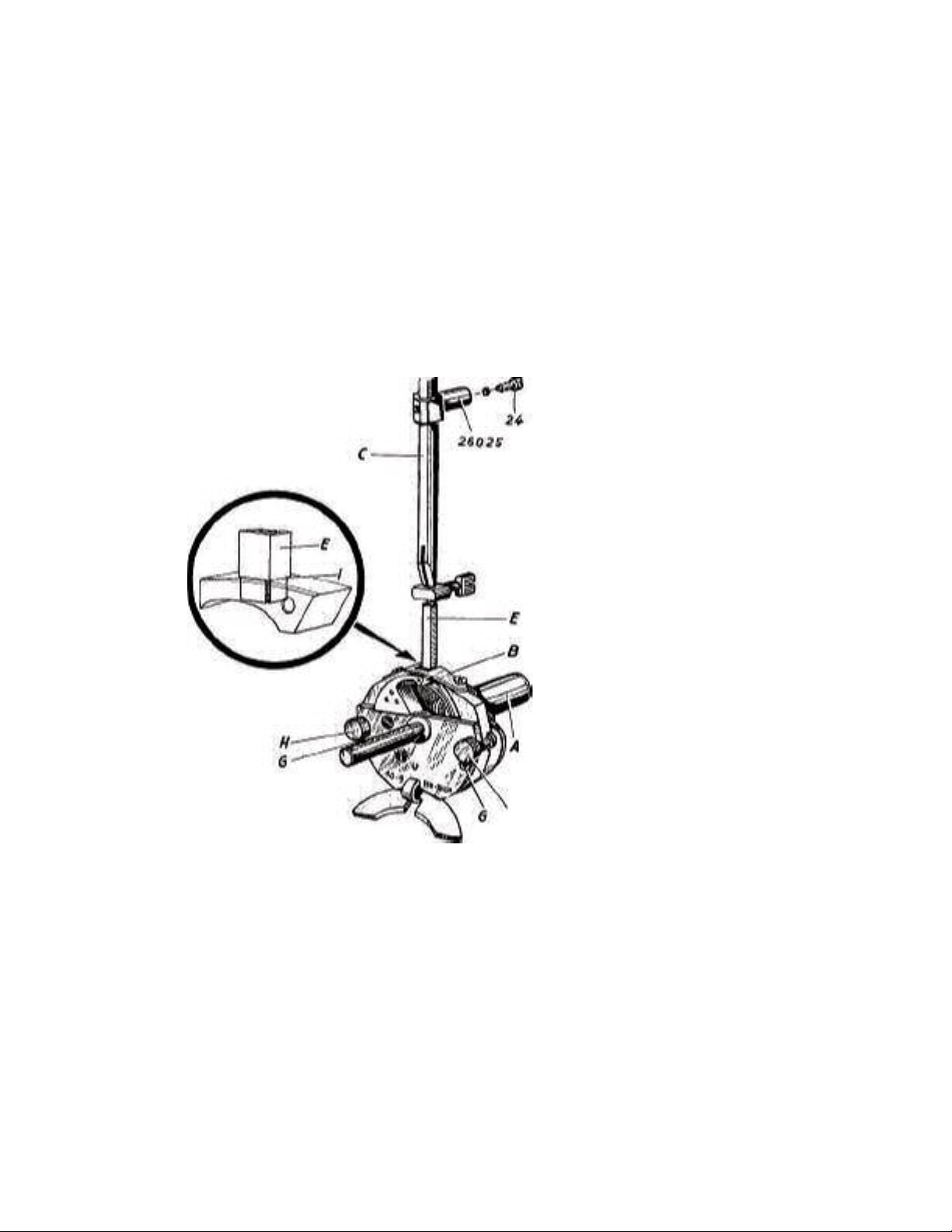
Insertion of the Timing Gauge No. 10-9 and of the
Square-angled Bar E. (Fig. 27).
Remove the presser foot and the needle plate. Remove the
needle and the shuttle.
Insert bar " E " (Fig. 27) of the gauge into the needle bar,
following the same instructions as for the insertion of a
needle. Loosen screw No. 24 of the needle bar connecting
stud No. 26025 so that the needle bar is still held in position
by friction. Hold the balance wheel firmly and push the
needle bar upwards about 7/32".
H
Fig. 27
/) By turning the balance whee l toward you by hand, bring
the needle bar " C " to its lowest position.
From this point onward and during the timing operation, DO NOT
turn the machine.

Insert the gauge No. 10-9 into the race body and attach it by
30
Copyright -2004
means of the two knobs " H " and the two locating pins " G ".
Timing procedure.
If, by pushing down the needle bar by hand while the balance
wheel
Is held firmly, the lower end of the bar " E " enters exactly into
the
Rectangular hole in the prong of the gauge No. 10-9 (Fig. 27),
then
the requirements of paragraphs II, III, and IV have been satisfied.
In
Order to comply also with the requirements of paragraph I, push
the
Step “I " of the bar " E " further downward until it stops against
the
Outside of the gauge No. 10-9 (Fig. 27).
Now, tighten screw No. 24 and remove the gauge.
If , by pushing down the needle bar by hand, the lower end of
the
Bar “E " does not ente r the rectangular hole in the p rong of
the
Gauge No. 10-9, and then adjust as follows:
Loosen the screw " F " below the bed of the machine (Fig. 24) in
order to allow the race body No. D 26330 to be moved freely.
Move the race body No. D 26330 and the needle bar " C "
stimuli
tenuously until the lower end of the bar " E " enters the rectangu-
lar hole in the prong of the gauge.
Push down the step " I " of the bar " E " by hand (Fig. 27) until
it stops against the outside of the gauge.
Firmly tighten the screw No. 24 of the needle bar connecting stud.
No. 26025.
Firmly tighten th e screw " F " (Fig. 24) belo w the bed of the
machine.
/) Remove the gauge.
How to remove the gauge 10-9.
Rotate the balance wheel slightly, just enough to bring the lower
end of the bar " E " out of the hole in the gauge.
Remove the gauge No. 10-9 from the shuttle race.
Remove the bar " E ".
Reassemble the machine.
 Loading...