

Page 1

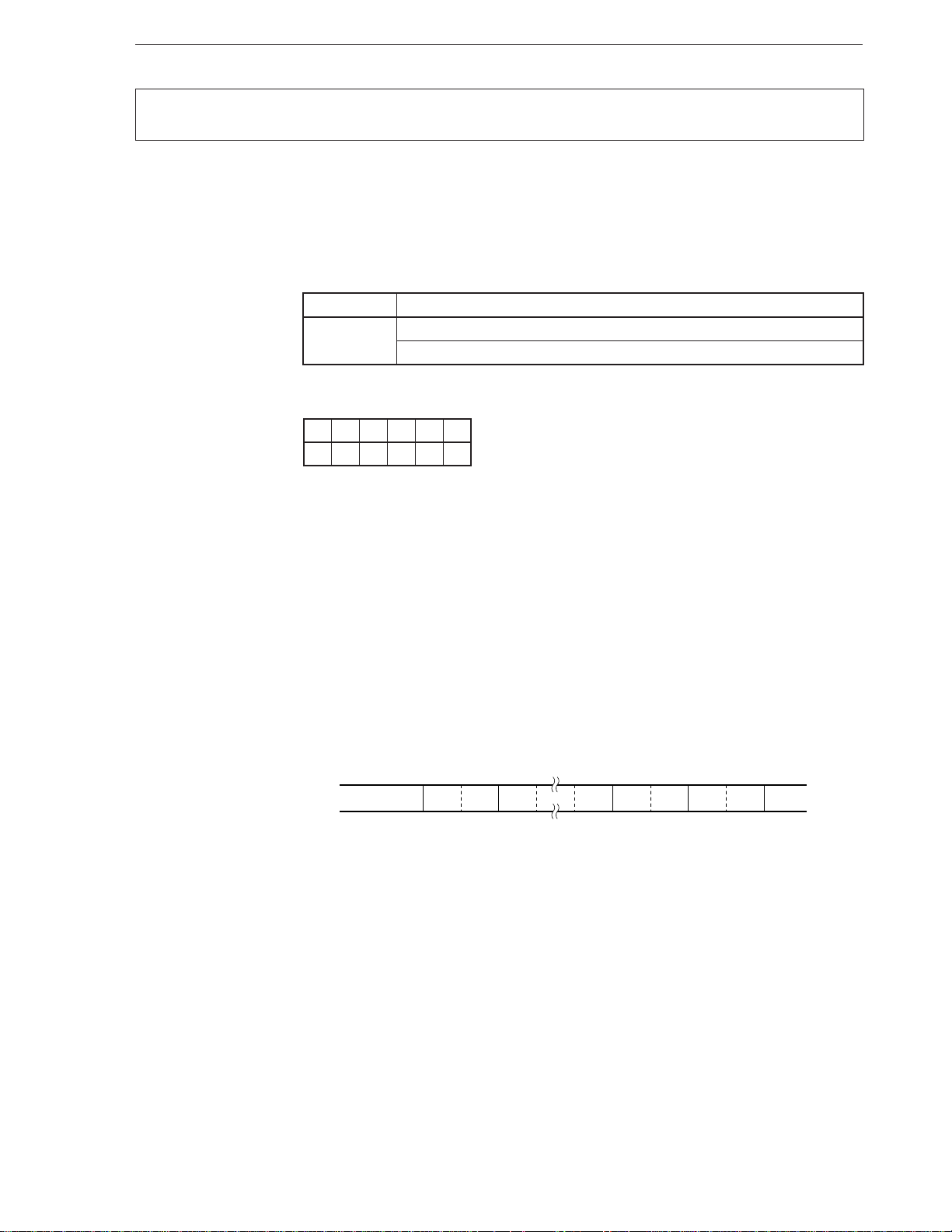
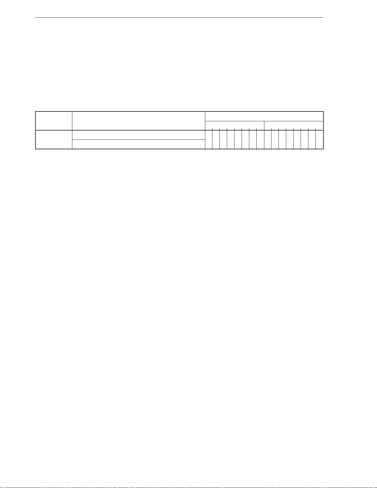
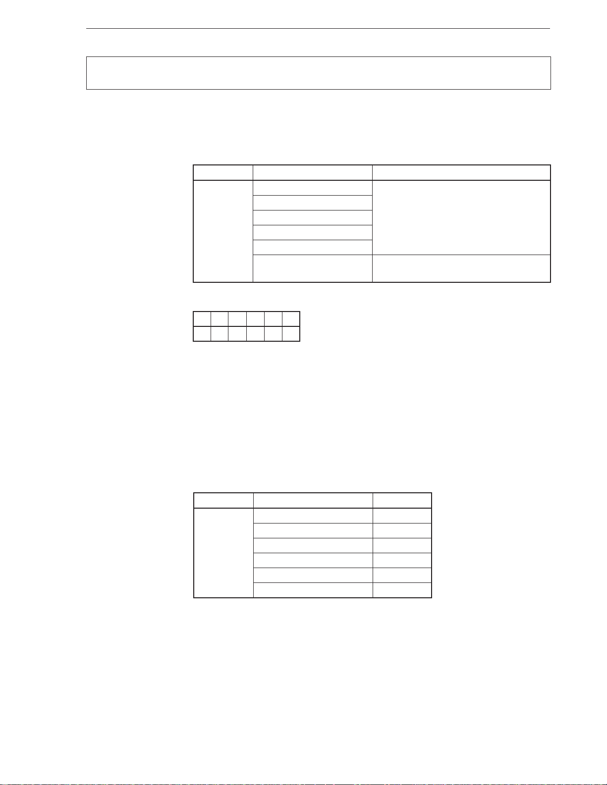
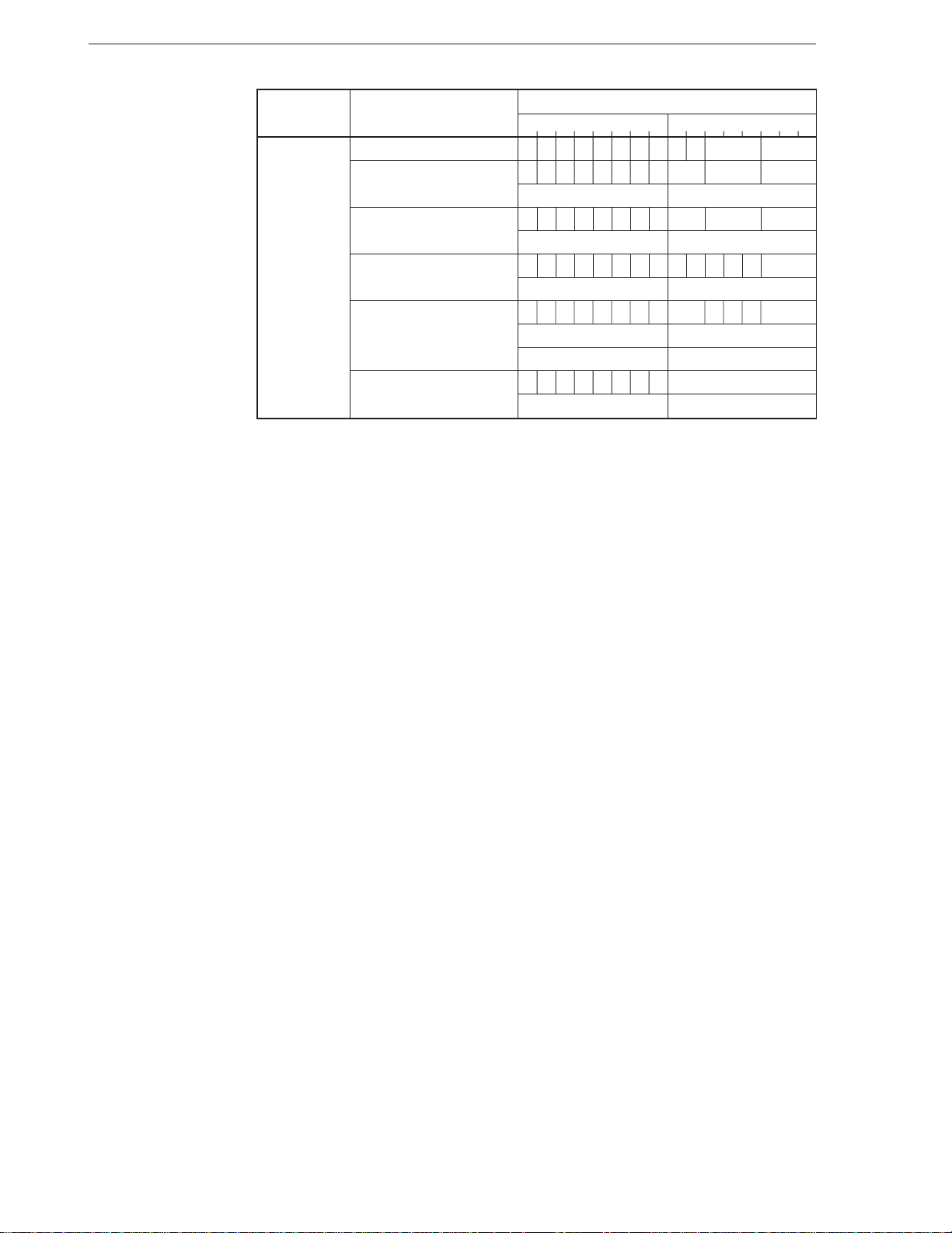
TM
16-BIT V SERIES
16-/8- AND 16-BIT MICROPROCESSORS
INSTRUCTION
V20TM, V30
V20HLTM, V30HL
V40TM, V50
V40HLTM, V50HL
V33A
V53A
Document No. U11301EJ5V0UM00 (5th edition)
Date Published June 1997 N
©
1996
Printed in Japan
TM
TM
TM
TM
TM
TM
Page 2

NOTES FOR CMOS DEVICES
1 PRECAUTION AGAINST ESD FOR SEMICONDUCTORS
Note:
Strong electric field, when exposed to a MOS device, can cause destruction of the gate oxide and
ultimately degrade the device operation. Steps must be taken to stop generation of static electricity
as much as possible, and quickly dissipate it once, when it has occurred. Environmental control
must be adequate. When it is dry, humidifier should be used. It is recommended to avoid using
insulators that easily build static electricity. Semiconductor devices must be stored and transported
in an anti-static container, static shielding bag or conductive material. All test and measurement
tools including work bench and floor should be grounded. The operator should be grounded using
wrist strap. Semiconductor devices must not be touched with bare hands. Similar precautions need
to be taken for PW boards with semiconductor devices on it.
2 HANDLING OF UNUSED INPUT PINS FOR CMOS
Note:
No connection for CMOS device inputs can be cause of malfunction. If no connection is provided
to the input pins, it is possible that an internal input level may be generated due to noise, etc., hence
causing malfunction. CMOS devices behave differently than Bipolar or NMOS devices. Input levels
of CMOS devices must be fixed high or low by using a pull-up or pull-down circuitry. Each unused
pin should be connected to V
being an output pin. All handling related to the unused pins must be judged device by device and
related specifications governing the devices.
DD or GND with a resistor, if it is considered to have a possibility of
3 STATUS BEFORE INITIALIZATION OF MOS DEVICES
Note:
Power-on does not necessarily define initial status of MOS device. Production process of MOS
does not define the initial operation status of the device. Immediately after the power source is
turned ON, the devices with reset function have not yet been initialized. Hence, power-on does
not guarantee out-pin levels, I/O settings or contents of registers. Device is not initialized until the
reset signal is received. Reset operation must be executed immediately after power-on for devices
having reset function.
Page 3

V20, V30, V20HL, V30HL, V40, V50, V40HL, V50HL, V33A, V53A, and V series are trademarks of NEC
Corporation.
InterTool is a trademark of Intermetrics Microsystems Software, Inc.
The information in this document is subject to change without notice.
No part of this document may be copied or reproduced in any form or by any means without the prior written
consent of NEC Corporation. NEC Corporation assumes no responsibility for any errors which may appear in
this document.
NEC Corporation does not assume any liability for infringement of patents, copyrights or other intellectual property
rights of third parties by or arising from use of a device described herein or any other liability arising from use
of such device. No license, either express, implied or otherwise, is granted under any patents, copyrights or other
intellectual property rights of NEC Corporation or others.
While NEC Corporation has been making continuous effort to enhance the reliability of its semiconductor devices,
the possibility of defects cannot be eliminated entirely. To minimize risks of damage or injury to persons or
property arising from a defect in an NEC semiconductor device, customers must incorporate sufficient safety
measures in its design, such as redundancy, fire-containment, and anti-failure features.
NEC devices are classified into the following three quality grades:
"Standard", "Special", and "Specific". The Specific quality grade applies only to devices developed based on a
customer designated “quality assurance program“ for a specific application. The recommended applications of
a device depend on its quality grade, as indicated below. Customers must check the quality grade of each device
before using it in a particular application.
Standard: Computers, office equipment, communications equipment, test and measurement equipment,
audio and visual equipment, home electronic appliances, machine tools, personal electronic
equipment and industrial robots
Special: Transportation equipment (automobiles, trains, ships, etc.), traffic control systems, anti-disaster
systems, anti-crime systems, safety equipment and medical equipment (not specifically designed
for life support)
Specific: Aircrafts, aerospace equipment, submersible repeaters, nuclear reactor control systems, life
support systems or medical equipment for life support, etc.
The quality grade of NEC devices is "Standard" unless otherwise specified in NEC's Data Sheets or Data Books.
If customers intend to use NEC devices for applications other than those specified for Standard quality grade,
they should contact an NEC sales representative in advance.
Anti-radioactive design is not implemented in this product.
M7 96.5
Page 4

Regional Information
Some information contained in this document may vary from country to country. Before using any NEC
product in your application, please contact the NEC office in your country to obtain a list of authorized
representatives and distributors. They will verify:
• Device availability
• Ordering information
• Product release schedule
• Availability of related technical literature
• Development environment specifications (for example, specifications for third-party tools and
components, host computers, power plugs, AC supply voltages, and so forth)
• Network requirements
In addition, trademarks, registered trademarks, export restrictions, and other legal issues may also vary
from country to country.
NEC Electronics Inc. (U.S.)
Santa Clara, California
Tel: 800-366-9782
Fax: 800-729-9288
NEC Electronics (Germany) GmbH
Duesseldorf, Germany
Tel: 0211-65 03 02
Fax: 0211-65 03 490
NEC Electronics (UK) Ltd.
Milton Keynes, UK
Tel: 01908-691-133
Fax: 01908-670-290
NEC Electronics Italiana s.r.1.
Milano, Italy
Tel: 02-66 75 41
Fax: 02-66 75 42 99
NEC Electronics (Germany) GmbH
Benelux Office
Eindhoven, The Netherlands
Tel:040-2445845
Fax: 040-2444580
NEC Electronics (France) S.A.
Velizy-Villacoublay, France
Tel:01-30-67 58 00
Fax: 01-30-67 58 99
NEC Electronics (France) S.A.
Spain Office
Madrid, Spain
Tel: 01-504-2787
Fax: 01-504-2860
NEC Electronics (Germany) GmbH
Scandinavia Office
Taeby, Sweden
Tel: 08-63 80 820
Fax: 08-63 80 388
NEC Electronics Hong Kong Ltd.
Hong Kong
Tel:2886-9318
Fax: 2886-9022/9044
NEC Electronics Hong Kong Ltd.
Seoul Branch
Seoul, Korea
Tel: 02-528-0303
Fax: 02-528-4411
NEC Electronics Singapore Pte. Ltd.
United Square, Singapore 1130
Tel:253-8311
Fax: 250-3583
NEC Electronics Taiwan Ltd.
Taipei, Taiwan
Tel: 02-719-2377
Fax: 02-719-5951
NEC do Brasil S.A.
Sao Paulo-SP, Brasil
Tel: 011-889-1680
Fax: 011-889-1689
J96. 8
Page 5

MAJOR REVISIONS IN THIS EDITION
Pages Contents
Throughout The following products have been deleted:
•µPD70208 (A) (V40)
•µPD70216 (A) (V50)
•µPD70270 (V41TM)
•µPD70280 (V51TM)
The mark shows major revised points.
Page 6
PREFACE
Readers This manual is intended for engineers who wish to understand the functions of the
following 16-bit V series microprocessors and design application systems using them.
Parts Number Nick Name
µ
PD70108 V20
µ
PD70116 V30
µ
PD70108H V20HL
µ
PD70116H V30HL
µ
PD70208 V40
µ
PD70216 V50
µ
PD70208H V40HL
µ
PD70216H V50HL
µ
PD70136A V33A
µ
PD70236A V53A
Purpose This manual is to introduce the instruction functions of the above 16-bit V series
microprocessors.
Organization Two volumes of the User’s Manual of the above 16- bit V series microprocessors are
available: Hardware Manual and Instruction Manual (this manual).
Hardware Manual Instruction Manual
General General
Pin Function Instruction Description
CPU Function Instruction Map
µ
Internal Block Function Correspondence of Mnemonic between
PD8086 and 8088
Bus Control Function
Interrupt Function
Standby Function
Reset Function
Others
Page 7

How to Read This Manual It is assumed that readers of this manual have a basic knowledge of electricity, logic
circuits, and microcontrollers. Unless otherwise specified, the descriptions in this
manual apply to all the models in the 16-bit V series microprocessors. Note that part
µ
number “
To check the details of the function of an instruction whose mnemonic is known,
→ Refer to CHAPTER 2 INSTRUCTIONS (instructions are shown in alphabetic order
To understand the details of each instruction,
→ Read this manual in the order of the Table of Contents.
To understand the hardware functions of each product,
→ Refer to the User’s Manual - Hardware (separate volume) for each product.
To find the electrical specifications
→ Refer to the data sheet for each product.
Legend Data significance : Left: high, right: low
Active low : ××× (top bar over pin or signal name)
Memory map address : Top: high, bottom: low
Address representation : x indicates a segment value, and y indicates an offset value
Note : Explanation of items marked with Note in the text
Caution : Important information
Remark : Supplement
Numeric notation : Binary ... ×××× or ××××B
PD70...” is referred to as “V...” in this manual.
of the mnemonic)
in the following case:
x: yH
Decimal ... ××××
Hexadecimal ... ××××H
Page 8
Related documents The documents referred to in this publication may include preliminary versions. However,
preliminary versions are not marked as such.
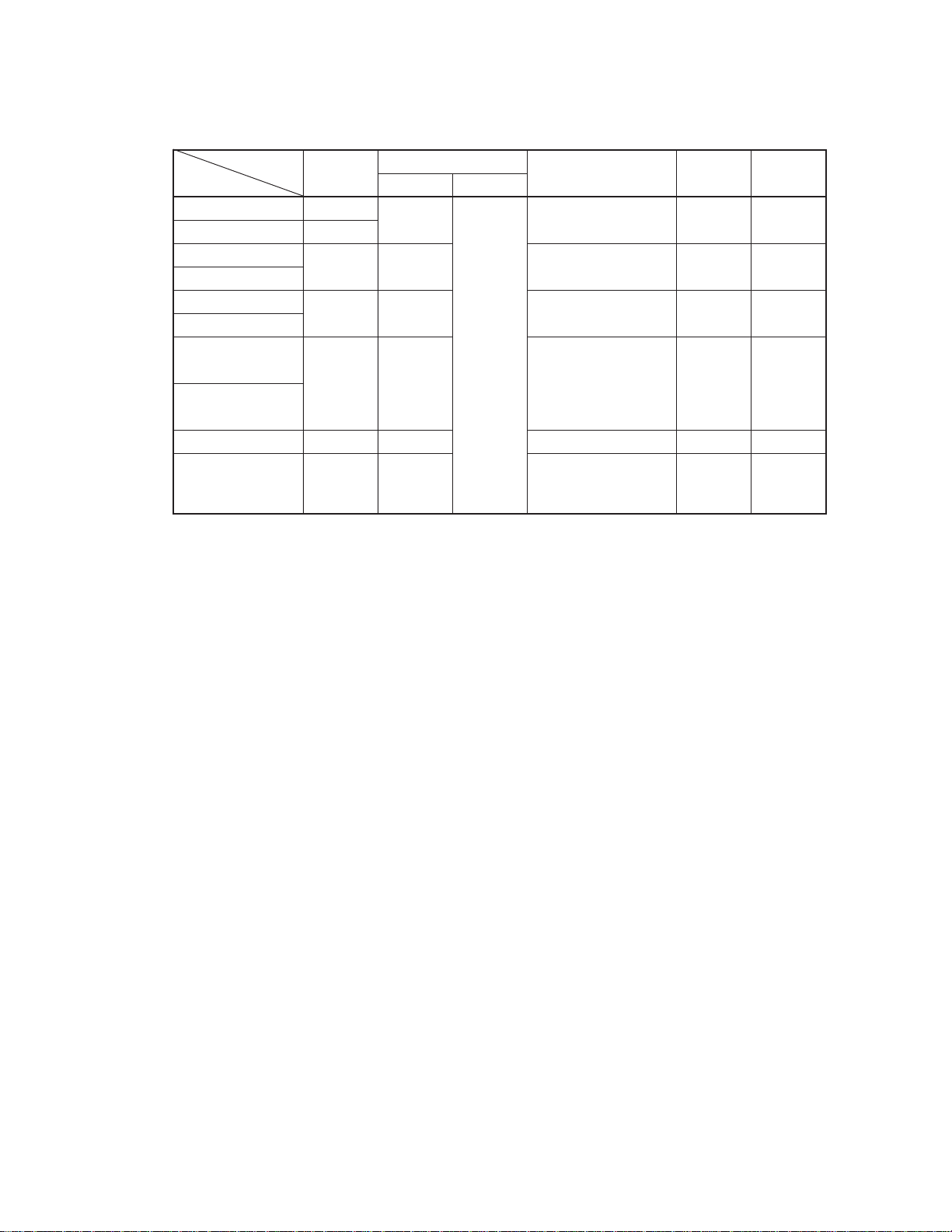
Document Data Sheet User’s Manual Application Note Register Q & A
Parts Number Hardware Instruction Table
V20 IC-1827 IEM-871 This – – –
V30 IC-1828 manual
V20HL IC-3552 IEU-761 – – –
V30HL
V40 U10154E U10666E U10911E – U10554E
V50 Software
V40HL IC-3659 U11610E U10037E – U11123E
Hardware Design
V50HL U10911E
Software
V33A U10136E U10032E – – –
V53A U10120E U10108E U10188E – U10875E
Address Expansion,
Software
Page 9

[MEMO]
Page 10

TABLE OF CONTENTS
CHAPTER 1 GENERAL ............................................................................................................................ 1
1.1 Classification of Instructions by Function ........................................................................2
1.2 Instruction Word Format ..................................................................................................... 3
1.3 Functional Outline of Each Instruction ..............................................................................3
1.3.1 Data transfer instructions ........................................................................................................... 3
1.3.2 Block manipulation instructions.................................................................................................. 3
1.3.3 Bit field manipulation instructions............................................................................................... 3
1.3.4 I/O instructions ........................................................................................................................... 4
1.3.5 Operation instructions ................................................................................................................ 4
1.3.6 BCD operation instructions ........................................................................................................ 4
1.3.7 BCD adjustment instructions...................................................................................................... 5
1.3.8 Data conversion instruction........................................................................................................ 5
1.3.9 Bit manipulation instructions ...................................................................................................... 5
1.3.10 Shift and rotate instructions........................................................................................................ 5
1.3.11 Stack manipulation instructions.................................................................................................. 5
1.3.12 Program branch instructions ...................................................................................................... 6
1.3.13 CPU control instructions............................................................................................................. 6
1.3.14 Mode select instructions............................................................................................................. 6
CHAPTER 2 INSTRUCTIONS ................................................................................................................... 7
2.1 Description of Instructions (in alphabetical order of mnemonic)....................................7
2.2 Number of Instruction Execution Clocks....................................................................... 169
APPENDIX A REGISTER CONFIGURATION ....................................................................................... 185
A.1 General-Purpose Registers (AW, BW, CW, DW)............................................................185
A.2 Segment Registers (PS, SS, DS0, DS1).......................................................................... 185
A.3 Pointers (SP, BP) ............................................................................................................. 185
A.4 Program Counter (PC) ..................................................................................................... 185
A.5 Program Status Word (PSW)........................................................................................... 186
A.6 Index Registers (IX, IY) .................................................................................................... 190
APPENDIX B ADDRESSING MODES .................................................................................................. 191
B.1 Instruction Address ......................................................................................................... 191
B.2 Memory Operand Address .............................................................................................. 193
APPENDIX C INSTRUCTION MAP ....................................................................................................... 199
APPENDIX D CORRESPONDENCE OF MNEMONICS OF µPD8086 AND 8088 ................................203
APPENDIX E INSTRUCTION INDEX (mnemonic: by function).......................................................... 205
APPENDIX F INSTRUCTION INDEX (mnemonic: alphabetical order) ..............................................207
– i –
Page 11

LIST OF FIGURES
Figure No. Title Page
1-1 Relations between Common Instructions and Dedicated Instructions of Each Model........................... 1
1-2 Instruction Format .................................................................................................................................. 3
1-3 Operation of ALU When Operation Instruction Is Executed................................................................... 4
2-1 Description Example ............................................................................................................................ 12
A-1 PSW Configuration............................................................................................................................. 186
LIST OF TABLES
Table No. Title Page
1-1 Classification of Instructions by Function............................................................................................... 2
2-1 Example of Flag Operation .................................................................................................................... 7
2-2 Example of Operand Type ..................................................................................................................... 8
2-3 Example of Instruction Word.................................................................................................................. 9
2-4 Legend of Description of Instruction Format and Operand .................................................................. 10
2-5 Memory Addressing ............................................................................................................................. 11
2-6 Selecting 8-/16-Bit General-Purpose Register ..................................................................................... 11
2-7 Selecting Segment Register................................................................................................................. 11
2-8 Number of Instruction Execution Clocks ............................................................................................ 170
C-1 Instruction Map................................................................................................................................... 200
C-2 Group1, Group2, Imm, and Shift Codes ............................................................................................ 202
C-3 Group0 Codes.................................................................................................................................... 202
C-4 Group3 Codes.................................................................................................................................... 202
µ
D-1 Register Correspondence with
D-2 Mnemonic Correspondence with µPD8086 and 8088 ....................................................................... 204
PD8086 and 8088........................................................................... 203
– ii –
Page 12

CHAPTER 1 GENERAL
The 16-bit V series microprocessors have 101 common instructions that are completely compatible in terms of
software, so that your software resources can be effectively utilized.
In addition to these common instructions, the V20, V30, V20HL, V30HL, V40, V50, V40HL, and V50HL have three
dedicated instructions (BRKEM, RETEM, and CALLN) to support emulation mode.
The V33A and V53A have two dedicated instructions (BRKXA and RETXA) to support the extended address mode.
Figure 1-1. Relations between Common Instructions and Dedicated Instructions of Each Model
V20, V30, V20HL, V30HL,
V40 V50 V40HL, V50HL,
Dedicated emulation
mode instructions
BRKEM
RETEM
CALLN
16-bit V series common instructions (101 types)
V33A, V53A
Dedicated extended
address mode
instructions
BRKXA
RETXA
Remark For the emulation mode and extended address mode, refer to the Hardware Manual of each model.
1
Page 13

CHAPTER 1 GENERAL
1.1 Classification of Instructions by Function
The instructions of the 16-bit V series can be broadly divided by classification of function into the following 27 types.
Table 1-1. Classification of Instructions by Function
Instruction Group Mnemonic (alphabetical order)
Data transfer instructions LDEA, MOV, TRANS, TRANSB, XCH
Repeat prefix REP, REPC, REPE, REPNC, REPNE, REPNZ, REPZ
Primitive block transfer instructions CMPBK, CMPBKB, CMPBKW, CMPM, CMPMB, CMPMW, LDM, LDMB,
LDMW, MOVBK, MOVBKB, MOVBKW, STM, STMB, STMW
Bit field manipulation instructions EXT, INS
I/O instructions IN, OUT
Primitive I/O instructions INM, OUTM
Add/subtract instructions ADD, ADDC, SUB, SUBC
BCD operation instructions ADD4S, CMP4S, ROL4, ROR4, SUB4S
Increment/decrement instructions DEC, INC
Multiplication/division instructions DIV, DIVU, MUL, MULU
BCD adjustment instructions ADJ4A, ADJ4S, ADJBA, ADJBS
Data conversion instructions CVTBD, CVTBW, CVTDB, CVTWL
Compare instructions CMP
Complement operation instructions NEG, NOT
Logical operation instructions AND, OR, TEST, XOR
Bit manipulation instructions CLR1, NOT1, SET1, TEST1
Shift instructions SHL, SHR, SHRA
Rotate instructions ROL, ROLC, ROR, RORC
Subroutine control instructions CALL, RET
Stack manipulation instructions DISPOSE, POP, PREPARE, PUSH
Branch instruction BR
Conditional branch instructions BC, BCWZ, BE, BGE, BGT, BH, BL, BLE, BLT, BN, BNC, BNE, BNH,
BNL, BNV, BNZ, BP, BPE, BPO, BZ, BV, DBNZ, DBNZE, DBNZNE
Interrupt instructions BRK, BRKV, CHKIND, RETI
CPU control instructions BUSLOCK, DI, EI, FPO1, FPO2, HALT, NOP, POLL
Segment override prefix DS0:, DS1:, PS:, SS:
Dedicated emulation mode instructions
Dedicated extended address mode instructions
Note 1
Note 2
BRKEM, CALLN, RETEM
BRKXA, RETXA
Notes 1. Except V33A and V53A
2. V33A and V53A only
2
Page 14
CHAPTER 1 GENERAL
1.2 Instruction Word Format
Basically, an instruction word (object code) is in the following format.
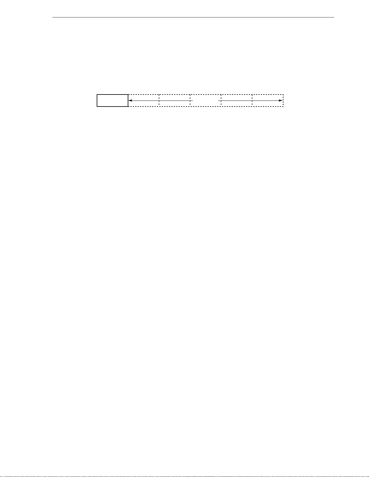
Figure 1-2. Instruction Format
OP CODE Operand
Remark op code : 8-bit code indicating type of instruction
Operand : Field indicating register and memory address to be manipulated by instructions. Indicated
as a field of 0 to 5 bytes.
1.3 Functional Outline of Each Instruction
1.3.1 Data transfer instructions
The data transfer instructions transfer data between two registers and between a register and memory, without
data manipulation. These instructions can be classified into the following four types.
To transfer general data (MOV) : Transfers a specified byte/word from the second operand to the first
operand. Can also directly transfer a numeric value to a register or
memory.
To transfer effective address (LDEA) : Transfers the offset address (effective address) of the second operand
to the first operand.
To transfer conversion table (TRANS): Transfers 1 byte of a conversion table.
Exchanges general data (XCH) : Exchanges the contents of the first operand with those of the second
operand.
1.3.2 Block manipulation instructions
A block (successive data) of bytes or words can be transferred or compared by using a repeat prefix and a primitive
block transfer instruction.
The primitive block transfer instructions transfer, compare, and scan data, like the instructions that transfer data
with the accumulator in block units. If a 1-byte repeat prefix is used, repetitive processing by hardware can be
performed so that data can be manipulated successively.
1.3.3 Bit field manipulation instructions
The bit field manipulation instructions can be used to transfer data of specified length between a specified bit field
area and the AW register, with a contiguous memory area regarded as the bit field.
These instructions update a word offset (IX or IY register) and bit offset (8-bit general-purpose register) and
automatically specify successive bit field data after the instructions have been executed. These instructions are useful
for computer graphics and high-level languages and can support, for example, packed array of Pascal and data
structure of record type.
3
Page 15
CHAPTER 1 GENERAL
1.3.4 I/O instructions
The I/O instructions and primitive I/O instructions can read/write I/O devices.
The I/O devices transfer data with the CPU via the data bus by using these instructions.
1.3.5 Operation instructions
The following instructions can execute 8-/16-bit data operations.
Add/subtract, increment/decrement, multiplication, division, compare, complement operation, logical operation
The increment/decrement instructions can increment (+1) or decrement (–1) the 8-/16-bit data of the general-
purpose registers or memory.
Each operation instruction is not executed in a register or memory whose contents are to be manipulated, but
actually executed in the ALU. The result of the operation is set (1) or reset (0) to the flags of the program status word
(PSW).
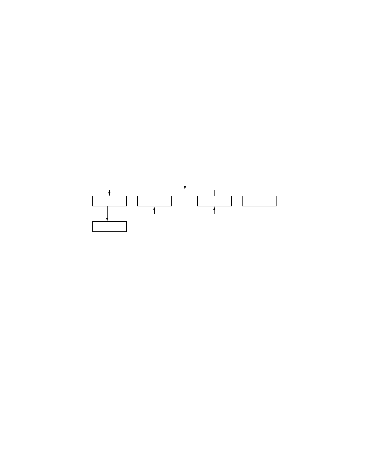
Figure 1-3. Operation of ALU When Operation Instruction Is Executed
Operation instruction
Operation ALU Register Memory Data
Set result of operation
Flag
Set status of operation result
1.3.6 BCD operation instructions
The BCD operation instructions can be used to represent decimal numbers by using hexadecimal numbers for
calculation.
These instructions can also be used to execute arithmetic operation or comparison of BCD strings in memory.
Instructions that support rotating the BCD strings are also included.
Because the operand and comparison instructions are used to manipulate specific registers, they do not have an
operand that specifies a packed BCD string.
The first address of the source string (address of the byte data including LSD) is specified by the contents of the
IX register in data segment 0 (DS0).
The first address (address of the byte data including LSD) of the destination string is specified by the contents
of the IY register in data segment 1 (DS1).
The number of digits is specified by the contents of the CL register.
Because the destination string and source string must be of the same length, 0 is extended to the length of longer
string if the lengths of the two are different.
4
Page 16

CHAPTER 1 GENERAL
1.3.7 BCD adjustment instructions
BCD operation is supported by executing a BCD adjustment instruction before or after arithmetic operation.
Because the BCD adjustment instructions are executed on the AL register, they do not have an operand. In the
case of addition and subtraction, adjustment can be made to both packed BCD and unpacked BCD. In the case of
multiplication and division, however, adjustment can be made to only unpacked BCD representation.
1.3.8 Data conversion instruction
The data conversion instructions can convert the type and word length of binary and decimal numbers.
The CVTBD and CVTDB instructions convert binary numbers and 2-digit unpacked BCD.
The CVTBW and CVTWL instructions extend the sign in a register.
1.3.9 Bit manipulation instructions
The bit manipulation instructions are used to execute logical operations on the bit data of the general-purpose
registers or memory.
The operand of the instruction format is “reg, bit” or “mem, bit”.
The first operand, reg or mem, specifies 8-/16-bit data including the bit data to be manipulated and codes a generalpurpose register or an effective address.
The second operand bit indicates the address of the bit data in a byte or word, and uses the contents of CL or
8-bit immediate data. If reg or mem is 8-bit data, only the low-order 3 bits are the valid bit address. If reg or mem
is 16-bit data, only the low-order 4 bits are the valid bit address, and the high-order bits are ignored.
1.3.10 Shift and rotate instructions
The shift or rotate instructions shift or rotate the 8-/16-bit data of a general-purpose register or memory 1 bit or
more (0 to 255).
The shift instructions are divided into arithmetic shift and logical shift instructions. Usually, the number of digits
to be shifted is 1, but it can be changed depending on the value of the CL register each time the instruction has been
executed if specified by the count operand of the instruction (255 max.). The arithmetic shift instruction inserts 0 to
the LSB of the data shifted if the data has been shifted 1 bit to the left, and 1 to the MSB of the data if the data has
been shifted 1 bit to the right. The logical shift instruction does not cause the value of the LSB or MSB to be changed
even when the data has been shifted 1 bit.
Like the shift instructions, the number of digits to be rotated by a rotate instruction is specified by the count operand
of the instruction. This value is the value stored to the CL register. As a result of executing the rotate instruction, the
CY and V flags are affected. The bit rotated out is always stored to the CY flag. The V flag always becomes undefined
if two or more digits have been rotated. If only one digit is rotated and the MSB (extension) of the destination is affected
as a result, the V flag is set to 1; otherwise, the flag is reset to 0. The CY flag can be used as the extension of the
destination when the ROLC or ROR instruction is used.
1.3.11 Stack manipulation instructions
The stack manipulation instructions are used to manipulate the stack in the memory.
The following four types of stack manipulation instructions are available.
PUSH : Saves data to the stack.
POP : Restores data from the stack.
PREPARE : Creates a stack frame and copies a frame pointer to secure an area for a local variable or to
reference a global variable.
DISPOSE : Restores the stack pointer (SP) and base pointer (BP) to the status before the PREPARE
instruction is executed.
5
Page 17

CHAPTER 1 GENERAL
1.3.12 Program branch instructions
These instructions branch program execution to specified addresses. The following four types of branch
instructions are available.
Subroutine control instructions : Save the contents of the program counter (PC) to the stack (CALL) or restore
the contents of the PC from the stack (RET).
Branch instruction : Branches the flow of an instruction to a specified address.
Conditional branch instructions : Branch the flow of instruction execution to a specified address depending
on the value of a flag.
Interrupt instructions : Temporarily stop execution of the program and controls flow of program
execution by means of software interrupts if an external device requests for
interrupt or if an operation error occurs.
1.3.13 CPU control instructions
The CPU control instructions manipulate flags, synchronize the processor with an external device, or transfer data.
An instruction that causes the CPU to execute nothing (NOP) is also available.
1.3.14 Mode select instructions
(1) Emulation mode (except V33A and V53A)
The mode can be changed between the native and emulation modes by using a dedicated emulation mode
instruction.
(2) Extended address mode (V33A and V53A only)
The mode can be changed between the normal address mode and extended address mode by using a
dedicated extended address mode instruction.
6
Page 18

CHAPTER 2 INSTRUCTIONS
2.1 Description of Instructions (in alphabetical order of mnemonic)
This chapter explains the following items for each instruction.
[Format]
[Operation]
[Operand]
[Flag]
[Description]
[Example]
[Number of bytes]
[Word format]
In [Format], [Operation], and [Operand], several identifiers are used.
Tables 2-2 through 2-4 show the identifiers used and their meanings, and Tables 2-5 through 2-7 explain how to
select memory addressing modes, general-purpose registers, and segment registers.
[Flag] shows, by using identifiers, the operations of the flags that are affected as a result of executing the given
instruction. Table 2-1 shows examples of operations of each flag.
Table 2-1. Example of Flag Operation
Identifier Description
Blank Not affected
0 Reset to 0
1 Set to 1
× Set to 1 or reset to 0 depending on result
U Undefined
R Restores previously saved value
7
Page 19

CHAPTER 2 INSTRUCTIONS
Table 2-2. Example of Operand Type
Identifier Description
reg 8-/16-bit general-purpose register
(destination register for instruction using two 8-/16-bit general-purpose registers)
reg’ Source register for instruction using two 8-/16-bit general-purpose registers
reg8 8-bit general-purpose register
(destination register for instruction using two 8-bit general-purpose registers)
reg8’ Source register for instruction using two 8-bit general-purpose registers
reg16 16-bit general-purpose register
(destination register for instruction using two 16-bit general-purpose registers)
reg16’ Source register for instruction using two 16-bit general-purpose registers
mem 8-/16-bit memory address
mem8 8-bit memory address
mem16 16-bit memory address
mem32 32-bit memory address
dmem 16-bit direct memory address
imm 8-/16-bit immediate data
imm3 3-bit immediate data
imm4 4-bit immediate data
imm8 8-bit immediate data
imm16 16-bit immediate data
acc Accumulator (AW or AL)
sreg Segment register
src-table Name of 256-byte conversion table
src-block Name of source block addressed by IX register
dst-block Name of destination block addressed by IY register
near-proc Procedure in current program segment
far-proc Procedure in other program segments
near-label Label in current program segment
short-label Label in range of end of instruction –128 to +127 bytes
far-label Label in other program segments
regptr16 16-bit general-purpose register having offset of call address in current program segment
memptr16 16-bit memory address having offset of call address in current program segment
memptr32 32-bit memory address having offset and segment data of call address in other program segments
pop-value Number of bytes discarded from stack (0 to 64K, usually even number)
fp-op Immediate value identifying instruction code of floating-point coprocessor
R Register set (AW, BW, CW, DW, SP, BP, IX, IY)
DS1-spec DS1 or segment name/group name ASSUMEd to DS1
Seg-spec Any segment register name or segment name/group name ASSUMEd to segment register
[ ] Can be omitted
8
Page 20

CHAPTER 2 INSTRUCTIONS
Table 2-3. Example of Instruction Word
Identifier Description
W Byte/word field (0, 1)
reg Register field (000 to 111)
reg’ Register field (000 to 111) (source register for instruction using two registers)
mod, mem Memory addressing specification bit (mod: 00 to 10, mem: 000 to 111)
(disp-low) Low-order byte of option 16-bit displacement
(disp-high) High-order byte of option 16-bit displacement
disp-low Low-order byte of 16-bit displacement for PC relative addition
disp-high High-order byte of 16-bit displacement for PC relative addition
imm3 3-bit immediate data
imm4 4-bit immediate data
imm8 8-bit immediate data
imm16-low Low-order byte of 16-bit immediate data
imm16-high High-order byte of 16-bit immediate data
addr-low Low-order byte of 16-bit direct address
addr-high High-order byte of 16-bit direct address
sreg Segment register specification bit (00 to 11)
s Sign extension specification bit (1: sign extension, 0: not sign extension)
offset-low Low-order byte of 16-bit offset data loaded to PC
offset-high High-order byte of 16-bit offset data loaded to PC
seg-low Low-order byte of 16-bit segment data loaded to PS
seg-high High-order byte of 16-bit segment data loaded to PS
pop-value-low Low-order byte of 16-bit data specifying number of bytes discarded from stack
pop-value-high High-order byte of 16-bit data specifying number of bytes discarded from stack
disp8 8-bit displacement relatively added to PC
X
XXX
YYY
ZZZ
Operation codes of floating-point coprocessor
9
Page 21

CHAPTER 2 INSTRUCTIONS
Table 2-4. Legend of Description of Instruction Format and Operand (1/2)
Identifier Description
dst Destination operand
dst1 Destination operand
dst2 Destination operand
src Source operand
src1 Source operand
src2 Source operand
target Target operand
AW Accumulator (16 bits)
AH Accumulator (high-order bytes)
AL Accumulator (low-order bytes)
BW BW register (16 bits)
CW CW register (16 bits)
CL CW register (low-order byte)
DW DW register (16 bits)
BP Base pointer (16 bits)
SP Stack pointer (16 bits)
PC Program counter (16 bits)
PSW Program status word (16 bits)
IX Index register (source) (16 bits)
IY Index register (destination) (16 bits)
PS Program segment register (16 bits)
SS Stack segment register (16 bits)
DS0 Data segment 0 register (16 bits)
DS1 Data segment 1 register (16 bits)
AC Auxiliary carry flag
CY Carry flag
P Parity flag
S Sign flag
Z Zero flag
DIR Direction flag
IE Interrupt enable flag
V Overflow flag
BRK Break mode
MD Mode flag (not provided to V33A and V53A)
(...) Memory contents indicated by ( )
disp Displacement (8/16 bits)
temp Temporary register (8/16/32 bits)
temp1 Temporary register (16 bits)
temp2 Temporary register (16 bits)
TA Temporary register A (16 bits)
TB Temporary register B (16 bits)
TC Temporary register C (16 bits)
ext-disp8 16-bits as result of sign-extending 8-bit displacement
seg Immediate segment data (16 bits)
offset Immediate offset data (16 bits)
10
Page 22
CHAPTER 2 INSTRUCTIONS
Table 2-4. Legend of Description on Instruction Format and Operand (2/2)
Identifier Description
← Transfer direction
+ Add
– Subtract
× Multiply
÷ Divide
% Modulo
^
Logical product (AND)
v Logical sum (OR)
v Exclusive logical sum (XOR)
××H 2-digit hexadecimal value
××××H 4-digit hexadecimal value
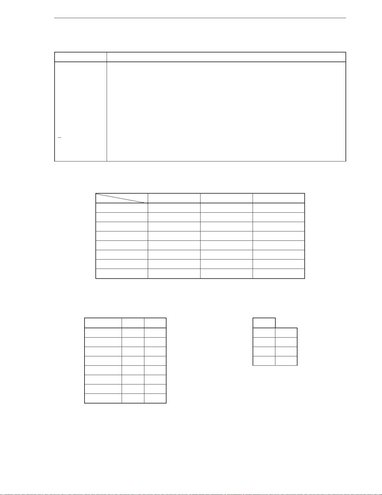
Table 2-5. Memory Addressing
mem
mod
000 BW+IX BW+IX+disp8 BW+IX+disp16
001 BW+IY BW+IY+disp8 BW+IY+disp16
010 BP+IX BP+IX+disp8 BP+IX+disp16
011 BP+IY BP+IY+disp8 BP+IY+disp16
100 IX IX+disp8 IX+disp16
101 IY IY+disp8 IY+disp16
110 Direct address BP+disp8 BP+disp16
111 BW BW+disp8 BW+disp16
00 01 10
Table 2-6. Selecting 8-/16-Bit General- Table 2-7. Selecting Segment Register
Purpose Register
reg, reg’ W = 0 W = 1 sreg
000 AL AW 00 DS1
001 CL CW 01 PS
010 DL DW 10 SS
011 BL BW 11 DS0
100 AH SP
101 CH BP
110 DH IX
111 BH IY
11
Page 23
CHAPTER 2 INSTRUCTIONS
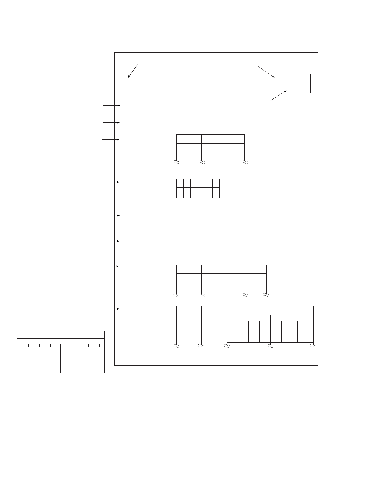
Figure 2-1. Description Example
Describes basic description format of
instruction by using symbols.
Describes operation of instruction by using
symbols.
Describes operands that can be specified
for this instruction. For the description of
the symbol of each operand, refer to Tables
2-2 through 2-4.
Describes operation of flags that are affected
as a result of instruction execution. For the
symbol of each flag, refer to Table 2-4. For
the symbol of flag operation, refer to Table
2-1.
Describes the operation of the instruction
in detail.
Mnemonic
Function
Addition
ADD
[Format] ADD dst, src
Full name
Add
[Operation] dst←dst+src
[Operand]
[Flag]
Mnemonic Operand (dst, src)
ADD reg, reg’
mem, reg
AC CY
VPSZ
ЧЧЧЧЧЧ
[Description] Adds the contents of the destination operand (dst) specified
by the first operand ...
Shows an example of description based on
the description format of RA70116-I
(InterTool
Indicates the instruction word length.
Indicates the instruction format. For the
symbol of each field, refer to Table 2-3.
The Operation Code column shows the
following byte order (6 bytes max.).
TM
).
Operation Code
7654321076543210
First byte Second byte
Third byte Fourth byte
Fifth byte Sixth byte
[Example] MOV AW, 0
[Number of bytes]
[Word format]
.
.
.
Mnemonic Operand
ADD reg, reg’ 2
mem, reg 2-4
Mnemonic Operand Operation Code
ADD reg, reg’ 0000000W11 reg reg’
mem, reg’ 0000000Wmod reg mem
No. of Bytes
7654321076543210
12
Page 24
CHAPTER 2 INSTRUCTIONS
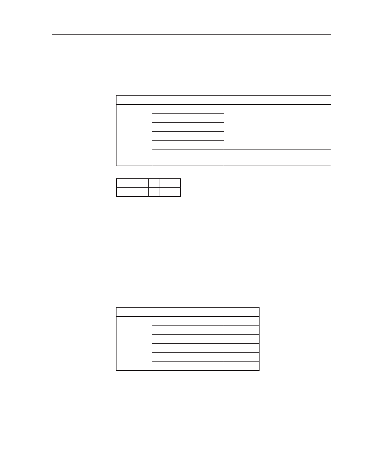
ADD
[Format] ADD dst, src
[Operand, Operation]
Mnemonic Operand (dst, src) Operation
ADD reg, reg’ dst ← dst + src
[Flag]
AC CY V P S Z
ЧЧЧЧЧЧ
Addition
Add
mem, reg
reg, mem
reg, imm
mem, imm
acc, imm [When W = 0] AL ← AL + imm8
[When W = 1] AW ← AW + imm16
[Description] Adds the contents of the destination operand (dst) specified by the first operand to the
contents of the source operand (src) specified by the second operand, and stores the result
to the destination operand (dst).
[Example] To add the contents of memory 0:50H (word data) to the contents of the DW register, and
store the result to 0:50H
MOV AW, 0
MOV DS1, AW
MOV IY, 50H
ADD DS1: WORD PTR [IY], DW
[Number of bytes]
Mnemonic Operand No. of bytes
ADD reg, reg’ 2
mem, reg 2-4
reg, mem 2-4
reg, imm 3, 4
mem, imm 3-6
acc, imm 2, 3
13
Page 25
CHAPTER 2 INSTRUCTIONS
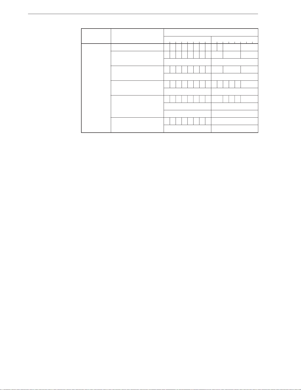
[Word format]
Mnemonic Operand
7654321076543210
ADD reg, reg’ 0000001W11 reg reg‘
mem, reg 0000000Wmod reg mem
(disp-low) (disp-high)
reg, mem 0000001Wmod reg mem
(disp-low) (disp-high)
reg, imm 100000sW11000 reg
imm8 or imm16-low imm16-high
mem, imm 100000sWmod000 mem
(disp-low) (disp-high)
imm8 or imm16-low imm16-high
acc, imm 0000010W imm8 or imm16-low
imm16-high —
Operation code
14
Page 26
CHAPTER 2 INSTRUCTIONS
ADD4S
Add Nibble String
[Format] ADD4S [DS1-spec:] dst-string, [Seg-spec:] src-string
ADD4S
[Operation] BCD string (IY, CL) ← BCD string (IY, CL) + BCD string (IX, CL)
Decimal addition
[Operand]
[Flag]
Mnemonic Operand (dst, src)
ADD4S [DS1-spec : ] dst-string, [Seg-spec : ] src-string
None
AC CY V P S Z
U × UUU×
[Description] Adds the packed BCD string addressed by the IX register to the packed BCD string
addressed by the IY register, and stores the the result of the string addressed by the IY
register. The string length (number of BCD digits) is determined by the CL register (the
number of digits is d if the contents of CL is d) in a range of 1 to 254 digits.
The destination string must be always located in a segment specified by the DS1 register,
the segment cannot be overridden. Although the default segment register of the source
string is the DS0 register, the segment can be overridden, and the string can be located
in a segment specified by any segment register.
The format of a packed BCD string is as follows.
Byte offset
Memory
Digit offset
+m
+CL 0+1+2+3+4
+0+1
IX
IY
↓
Caution The BCD string instruction always operates in units of an even number of
digits. If an even number of digits is specified, therefore, the result of the
operation and each flag operation are normal. If an odd number of digits
is specified, however, an operation of an even number of digits, or an odd
number of digits + 1, is executed. As a result, the result of the operation
is an even number of digits and each flag indicates an even number of
digits. To specify an odd number of digits, therefore, keep this in mind:
Execute the BCD addition instruction, if the number of digits is odd, after
clearing the high-order 4 bits of the most significant byte to “0”. As a result,
the carry is indicated by bit 4 of the most significant byte, and is not
reflected in the flag.
15
Page 27
CHAPTER 2 INSTRUCTIONS
[Example] MOV IX, OFFSET VAR_1
MOV IY, OFFSET VAR_2
MOV CL, 4
ADD4S
[Number of bytes] 2
[Word format]
Mnemonic Operand
7654321076543210
ADD4S [DS1-spec :] dst-string, [Seg-spec :] src-string 0000111100100000
None
Operation code
16
Page 28
CHAPTER 2 INSTRUCTIONS
ADDC
[Format] ADDC dst, src
[Operand, Operation]
Mnemonic Operand (dst, src) Operation
ADDC reg, reg’ dst ← dst + src + CY
[Flag]
AC CY V P S Z
ЧЧЧЧЧЧ
Addition with carry
Add with Carry
mem, reg
reg, mem
reg, imm
mem, imm
acc, imm [When W = 0] AL ← AL + imm8 + CY
[When W = 1] AW ← AW + imm16 + CY
[Description] Adds the contents of the destination operand (dst) specified by the first operand to the
contents of the source operand (src) specified by the second operand with the contents
of the CY flag, and stores the result to the destination operand (dst).
[Example] SET1 CY ; Sets CY flag to 1.
XOR AW, AW ; AW = 0
MOV BW, 0FFH ; BW = 0FFH
ADDC AW, BW ; Contents of AW register = 100H
[Number of bytes]
Mnemonic Operand No. of bytes
ADDC reg, reg’ 2
mem, reg 2-4
reg, mem 2-4
reg, imm 3, 4
mem, imm 3-6
acc, imm 2, 3
17
Page 29
CHAPTER 2 INSTRUCTIONS
[Word format]
Mnemonic Operand
7654321076543210
ADDC reg, reg’ 0001001W11 reg reg‘
mem, reg 0001000Wmod reg mem
(disp-low) (disp-high)
reg, mem 0001001Wmod reg mem
(disp-low) (disp-high)
reg, imm 100000sW11010 reg
imm8 or imm16-low imm16-high
mem, imm 100000sWmod010 mem
(disp-low) (disp-high)
imm8 or imm16-low imm16-high
acc, imm 0001010W imm8 or imm16-low
imm16-high —
Operation code
18
Page 30
CHAPTER 2 INSTRUCTIONS
ADJ4A
Adjust Nibble Add
[Format] ADJ4A
[Operation] Where AL ^ 0FH > 9 or AC = 1,
AL ← AL + 6
AC ← 1
Where AL > 9FH or CY = 1
AL ← AL + 60H
CY ← 1
Packed decimal adjustment of result of addition
[Operand]
[Flag]
Mnemonic Operand
ADJ4A None
AC CY V P S Z
××U×××
[Description] Adjusts the contents of the AL register resulting from addition of two packed decimal
numbers into one packed decimal number.
[Example] ADJ4A
[Number of bytes] 1
[Word format]
Mnemonic Operand
ADJ4A None 00100111
Operation code
76543210
19
Page 31
CHAPTER 2 INSTRUCTIONS
ADJ4S
[Format] ADJ4S
[Operation] Where AL ^ 0FH > 9 or AC = 1
AL ← AL – 6
AC ← 1
Where AL > 9FH or CY = 1
AL ← AL – 60H
CY ← 1
[Operand]
[Flag]
Mnemonic Operand
ADJ4S None
AC CY V P S Z
××U×××
Packed decimal adjustment of result of subtraction
Adjust Nibble Subtract
[Description] Adjusts the contents of the AL register resulting from subtracting two packed decimal
numbers into one packed decimal number.
[Example] SUB AW, BW
ADJ4S
[Number of bytes] 1
[Word format]
Mnemonic Operand
ADJ4S None 00101111
Operation code
76543210
20
Page 32
CHAPTER 2 INSTRUCTIONS
ADJBA
[Format] ADJBA
[Operation] Where AL ^ 0FH > 9 or AC = 1
AL ← AL + 6
AH ← AH + 1
AC ← 1
CY ← AC
AL ← AL ^ 0FH
[Operand]
[Flag]
Mnemonic Operand
ADJBA None
AC CY V P S Z
××UUUU
Unpacked decimal adjustment of result of addition
Adjust Byte Add
[Description] Adjusts the contents of the AL register resulting from adding two unpacked decimal
numbers into one unpacked decimal number. The high-order 4 bits become 0.
[Example] ADJBA
[Number of bytes] 1
[Word format]
Mnemonic Operand
ADJBA None 00110111
Operation code
76543210
21
Page 33
CHAPTER 2 INSTRUCTIONS
ADJBS
Unpacked decimal adjustment of result of subtraction
[Format] ADJBS
[Operation] Where AL ^ 0FH > 9 or AC = 1
AL ← AL – 6
AH ← AH – 1
AC ← 1
CY ← AC
AL ← AL ^ 0FH
[Operand]
[Flag]
Mnemonic Operand
ADJBS None
AC CY V P S Z
××UUUU
Adjust Byte Subtract
[Description] Adjusts the contents of the AL register resulting from subtracting two unpacked decimal
numbers into one unpacked decimal number. The high-order 4-bits become 0.
[Example] SUB AW, BW
ADJBS
[Number of bytes] 1
[Word format]
Mnemonic Operand
ADJBS None 00111111
Operation code
76543210
22
Page 34
CHAPTER 2 INSTRUCTIONS
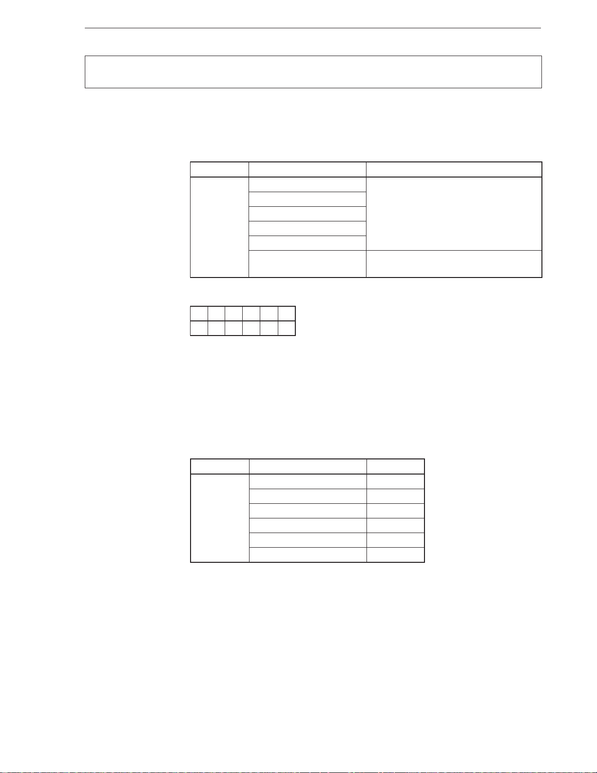
AND
[Format] AND dst, src
[Operand, Operation]
Mnemonic Operand (dst, src) Operation
AND reg, reg’ dst ← dst ^ src
[Flag]
AC CY V P S Z
U00×××
Logical product
And
mem, reg
reg, mem
reg, imm
mem, imm
acc, imm [When W = 0] AL ← AL ^ imm8
[When W = 1] AW ← AW ^ imm16
[Description] ANDs the contents of the destination operand (dst) specified by the first operand to the
contents of the source operand (src) specified by the second operand, and stores the result
to the destination operand (dst).
[Example] MOV DW, IY
AND DW, 7FFFH
[Number of bytes]
Mnemonic Operand No. of bytes
AND reg, reg’ 2
mem, reg 2-4
reg, mem 2-4
reg, imm 3, 4
mem, imm 3-6
acc, imm 2, 3
23
Page 35
CHAPTER 2 INSTRUCTIONS
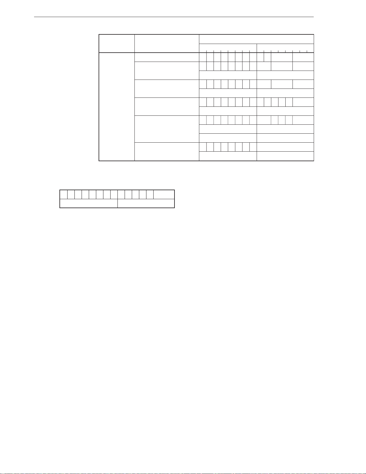
[Word format]
Mnemonic Operand
AND reg, reg’ 0010001W11 reg reg‘
mem, reg 0010000Wmod reg mem
reg, mem 0010001Wmod reg mem
reg, imm
mem, imm 1000000Wmod100 mem
acc, imm 0010010W imm8 or imm16-low
Note
7654321076543210
(disp-low) (disp-high)
(disp-low) (disp-high)
1000000W11100 reg
imm8 or imm16-low imm16-high
(disp-low) (disp-high)
imm8 or imm16-low imm16-high
imm16-high —
Operation code
Note The following code may be created depending on the assembler or compiler used.
7654321076543210
1000001W11100 reg
imm8 –
Even in this case, the instruction is executed normally. Note, however, that some emulators do not support
the functions to disassemble and assemble this instruction.
24
Page 36
CHAPTER 2 INSTRUCTIONS
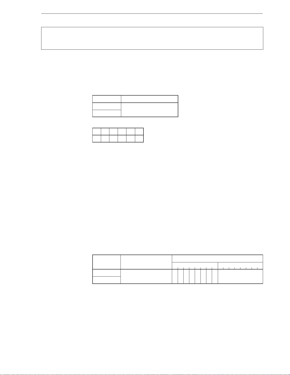
BC
BL
[Format] BC short-label
BL short-label
[Operation] Where CY = 1: PC ← PC + ext-disp8
[Operand]
[Flag]
[Description] Loads the current PC value with an 8-bit displacement added (actually, sign-extended 16
Mnemonic Operand
BC short-label
BL
AC CY V P S Z
bits) to the PC when the CY flag is 1.
Execution can be branched in a segment where this instruction is placed and in an address
range of –128 to +127 bytes.
Conditional branch where CY = 1
Branch if Carry
Branch if Lower
[Example] TEST AL, BL
BC SHORT LP4 ; LP4 = label
.
.
.
TEST AL, BL
BL SHORT LP5 ; LP5 = label
.
.
.
LP4:
[Number of bytes] 2
[Word format]
Mnemonic Operand
BC short-label 01110010 disp8
BL
Operation code
7654321076543210
25
Page 37
CHAPTER 2 INSTRUCTIONS
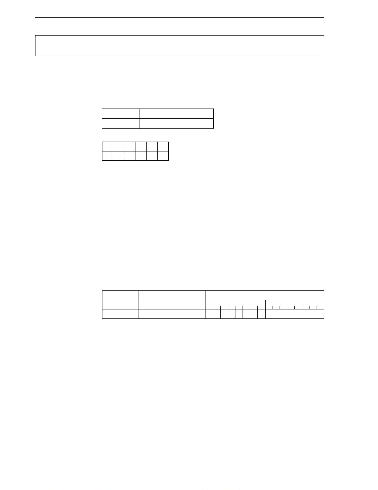
BCWZ
[Format] BCWZ short-label
[Operation] Where CW = 0: PC ← PC + ext-disp8
[Operand]
[Flag]
[Description] Loads the current PC value with an 8-bit displacement added (actually, sign-extended 16
Mnemonic Operand
BCWZ short-label
AC CY V P S Z
bits) to the PC if the value of the CW register is 0.
Execution can be branched in a segment where this instruction is placed and in an address
range of –128 to +127 bytes. If the above condition is not satisfied, execution goes on to
the next instruction.
Conditional branch where CW = 0
Branch if CW equals Zero
[Example] LP22:
[Number of bytes] 2
[Word format]
Mnemonic Operand
BCWZ short-label 11100011 disp8
.
.
.
ADD AL, BL
BCWZ SHORT LP22 ; LP22 = label
7654321076543210
Operation code
26
Page 38
CHAPTER 2 INSTRUCTIONS
BE
BZ
[Format] BE short-label
BZ short-label
[Operation] Where Z = 1: PC ← PC + ext-disp8
[Operand]
[Flag]
[Description] Loads the current PC value with an 8-bit displacement added (actually, sign-extended 16
Mnemonic Operand
BE short-label
BZ
AC CY V P S Z
bits) to the PC if the Z flag is 1.
Execution can be branched in a segment where this instruction is placed and in an address
range of –128 to +127 bytes.
Conditional branch where Z = 1
Branch if Equal
Branch if Zero
[Example] AND AL, 2
BE SHORT LOOP ; LOOP = label
.
.
.
OR AH, BH
BZ SHORT LOOP1 ; LOOP1 = label
.
.
.
LOOP:
[Number of bytes] 2
[Word format]
Mnemonic Operand
BE short-label 01110100 disp8
BZ
Operation code
7654321076543210
27
Page 39
CHAPTER 2 INSTRUCTIONS
BGE
[Format] BGE short-label
[Operation] Where S v
[Operand]
[Flag]
[Description] Loads the current PC value with an 8-bit displacement added (actually, sign-extended 16
Mnemonic Operand
BGE short-label
AC CY V P S Z
bits) to the PC if the result of exclusive OR (XOR) between the S and V flags is 0.
Execution can be branched in a segment where this instruction is placed and in an address
range of –128 to +127 bytes.
Execution goes on to the next instruction if the above condition is not satisfied.
V = 0: PC ← PC + ext-disp8
Conditional branch where S v V = 0
Branch if Greater Than or Equal
[Example] SHL AL, 1
BGE SHORT LP16 ; LP16 = label
.
.
.
LP16:
[Number of bytes] 2
[Word format]
Mnemonic Operand
BGE short-label 01111101 disp8
Operation code
7654321076543210
28
Page 40
CHAPTER 2 INSTRUCTIONS
BGT
[Format] BGT short-label
[Operation] (S v
[Operand]
[Flag]
[Description] Loads the current PC value with an 8-bit displacement added (actually, sign-extended 16
V) v Z = 0: PC ← PC + ext-disp8
Mnemonic Operand
BGT short-label
AC CY V P S Z
bits) to the PC if the result of ORing between the result of exclusive OR (XOR) of the S
and V flags, and the Z flag is 0.
Execution can be branched in a segment where this instruction is placed and in an address
range of –128 to +127 bytes.
Execution goes on to the next instruction if the above condition is not satisfied.
Conditional branch where (S v V) v Z = 0
Branch if Greater Than
[Example] LP18:
[Number of bytes] 2
[Word format]
Mnemonic Operand
BGT short-label 01111111 disp8
.
.
.
SHL AL, 1
BGT LP18
Operation code
7654321076543210
29
Page 41
CHAPTER 2 INSTRUCTIONS
BH
[Format] BH short-label
[Operation] Where CY v Z = 0: PC ← PC + ext-disp8
[Operand]
[Flag]
[Description] Loads the current PC value with an 8-bit displacement added (actually, sign-extended 16
Mnemonic Operand
BH short-label
AC CY V P S Z
bits) to the PC if the result of ORing the CY and Z flags is 0.
Execution can be branched in a segment where this instruction is placed and in an address
range of –128 to +127 bytes.
Conditional branch where CY v Z = 0
Branch if Higher
[Example] ROL AL, 1
BH SHORT LP10 ; LP10 = label
.
.
.
LP10:
[Number of bytes] 2
[Word format]
Mnemonic Operand
BH short-label 01110111 disp8
Operation code
7654321076543210
30
Page 42
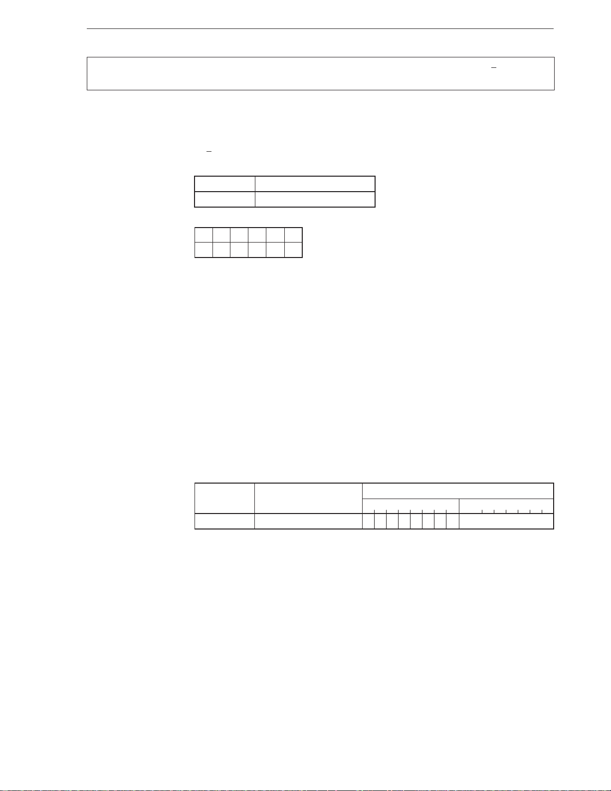
CHAPTER 2 INSTRUCTIONS
BLE
[Format] BLE short-label
[Operation] (S v
[Operand]
[Flag]
[Description] Loads the current PC value with an 8-bit displacement added (actually, sign-extended 16
V) v Z = 1: PC ← PC + ext-disp8
Mnemonic Operand
BLE short-label
AC CY V P S Z
bits) to the PC if the result of ORing between the result of exclusive OR (XOR) of the S
and V flags, and the Z flag is 1.
Execution can be branched in a segment where this instruction is placed and in an address
range of –128 to +127 bytes.
Execution goes on to the next instruction if the above condition is not satisfied.
Conditional branch where (S v V) v Z = 1
Branch if Less than or Equal
[Example] LP17:
[Number of bytes] 2
[Word format]
Mnemonic Operand
BLE short-label 01111110 disp8
.
.
.
SHR AL, 1
BLE SHORT LP17
Operation code
7654321076543210
31
Page 43

CHAPTER 2 INSTRUCTIONS
BLT
[Format] BLT short-label
[Operation] Where S v
[Operand]
[Flag]
[Description] Loads the current PC value with an 8-bit displacement added (actually, sign-extended 16
Mnemonic Operand
BLT short-label
AC CY V P S Z
bits) to the PC if the result of exclusive OR between the S and Z flags is 1.
Execution can be branched in a segment where this instruction is placed and in an address
range of –128 to +127 bytes.
Execution goes on to the next instruction if the above condition is not satisfied.
V = 1: PC ← PC + ext-disp8
Conditional branch where S v V = 1
Branch if Less Than
[Example] ADD AL, BL
BLT SHORT LP15 ; LP15 = label
.
.
LP15:
[Number of bytes] 2
[Word format]
BLT short-label 01111100 disp8
.
Mnemonic Operand
Operation code
7654321076543210
32
Page 44
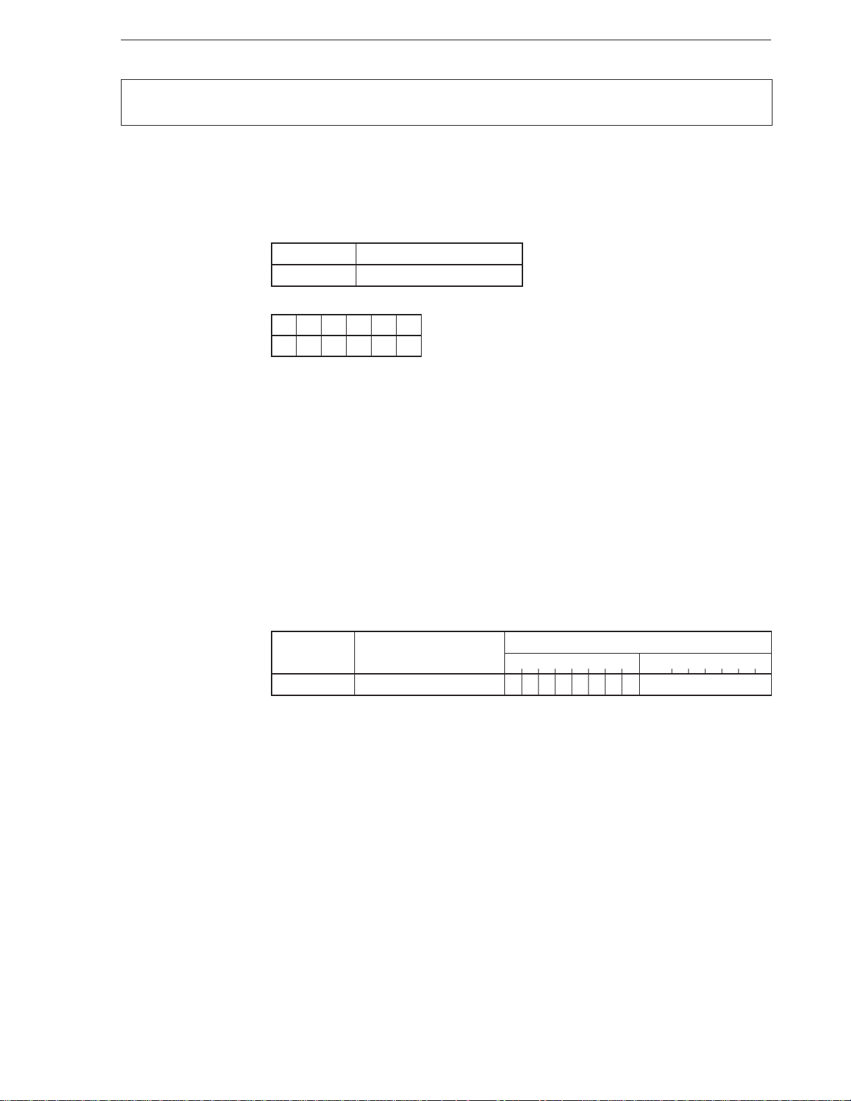
CHAPTER 2 INSTRUCTIONS
BN
[Format] BN short-label
[Operation] Where S = 1: PC ← PC + ext-disp8
[Operand]
[Flag]
[Description] Loads the current PC value with an 8-bit displacement added (actually, sign-extended 16
Mnemonic Operand
BN short-label
AC CY V P S Z
bits) to the PC if the S flag is 1.
Execution can be branched in a segment where this instruction is placed and in an address
range of –128 to +127 bytes.
Conditional branch where S = 1
Branch if Negative
[Example] ADD AL, BL
BN LP11 ; LP11 = label
.
.
.
LP11:
[Number of bytes] 2
[Word format]
Mnemonic Operand
BN short-label 01111000 disp8
Operation code
7654321076543210
33
Page 45
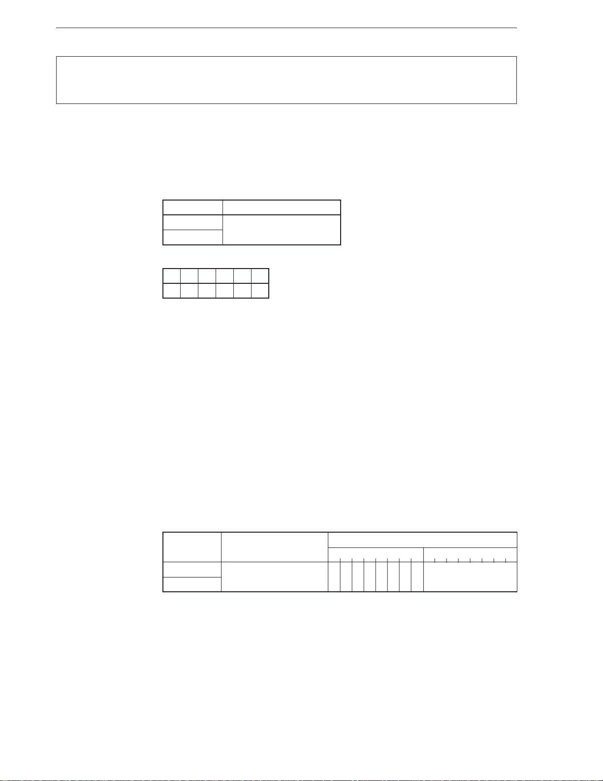
CHAPTER 2 INSTRUCTIONS
BNC
BNL
[Format] BNC short-label
BNL short-label
[Operation] Where CY = 0: PC ← PC + ext-disp8
[Operand]
[Flag]
[Description] Loads the current PC value with an 8-bit displacement added (actually, sign-extended 16
Mnemonic Operand
BNC short-label
BNL
AC CY V P S Z
bits) to the PC if the CY flag is 0.
Execution can be branched in a segment where this instruction is placed and in an address
range of –128 to +127 bytes.
Conditional branch where CY = 0
Branch if Not Carry
Branch if Not Lower
[Example] ROR AL, 1
BNC SHORT LP6 ; LP6 = label
.
.
.
ROR AL, 1
BNL SHORT LP7 ; LP7 = label
.
.
.
LP6:
[Number of bytes] 2
[Word format]
Mnemonic Operand
BNC short-label 01110011 disp8
BNL
Operation code
7654321076543210
34
Page 46
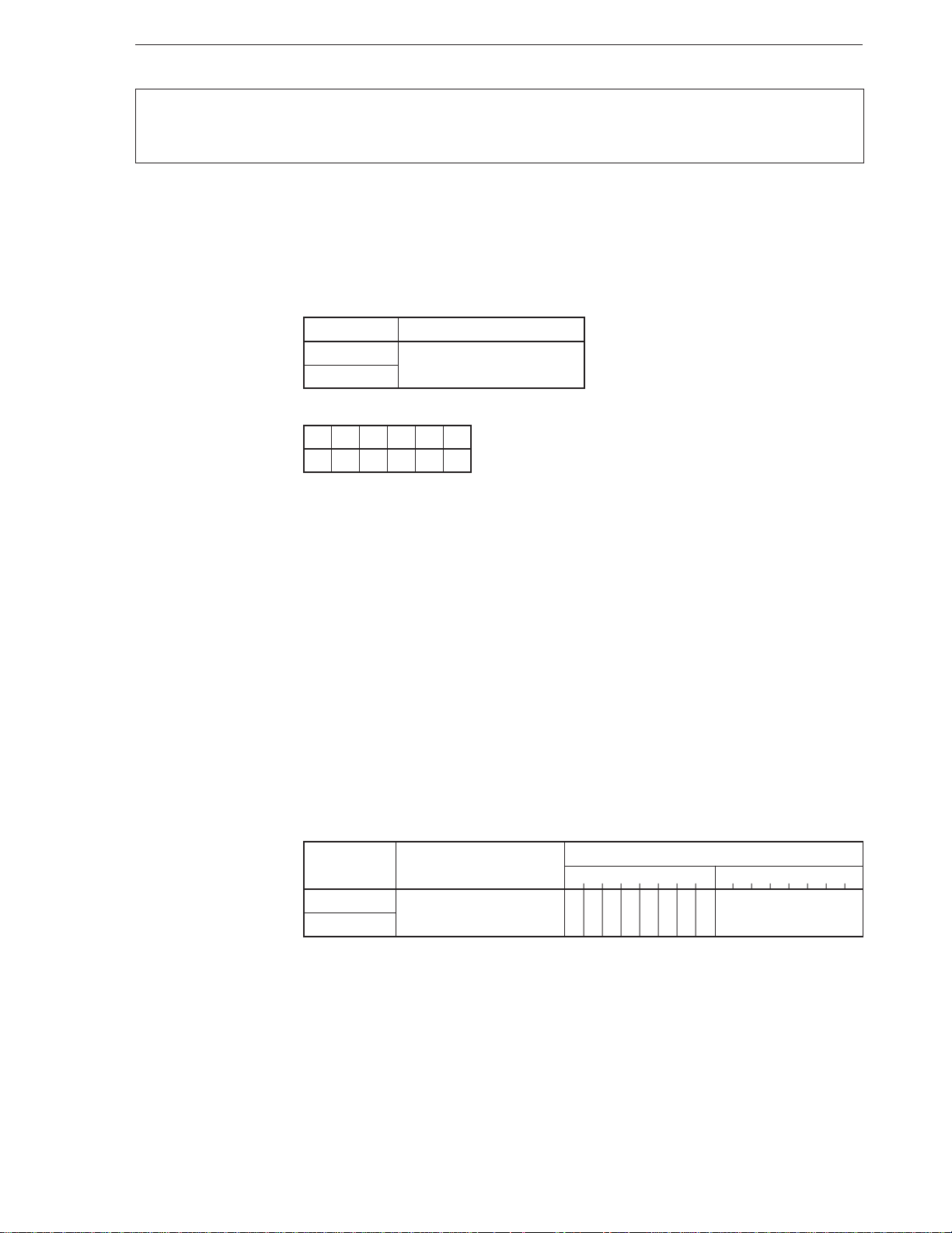
CHAPTER 2 INSTRUCTIONS
BNE
BNZ
[Format] BNE short-label
BNZ short-label
[Operation] Where Z = 0: PC ← PC + ext-disp8
[Operand]
[Flag]
[Description] Loads the current PC value with an 8-bit displacement added (actually, sign-extended 16
Mnemonic Operand
BNE short-label
BNZ
AC CY V P S Z
bits) to the PC if the Z flag is 0.
Execution can be branched in a segment where this instruction is placed and in an address
range of –128 to +127 bytes.
Conditional branch where Z = 0
Branch if Not Equal
Branch if Not Zero
[Example] OR AL, BL
BNE SHORT LP8 ; LP8 = label
.
.
.
AND SH, BH
BNZ SHORT LP9 ; LP9 = label
.
.
.
LP8:
[Number of bytes] 2
[Word format]
Mnemonic Operand
BNE short-label 01110101 disp8
BNZ
Operation code
7654321076543210
35
Page 47
CHAPTER 2 INSTRUCTIONS
BNH
[Format] BNH short-label
[Operation] Where CY v Z = 1: PC ← PC + ext-disp8
[Operand]
[Flag]
[Description] Loads the current PC value with an 8-bit displacement added (actually, sign-extended 16
Mnemonic Operand
BNH short-label
AC CY V P S Z
bits) to the PC if the result of OR between the CY and Z flags is 1.
Execution can be branched in a segment where this instruction is placed and in an address
range of –128 to +127 bytes.
Conditional branch where CY v Z = 1
Branch if Not Higher
[Example] ROR AL, 1
BNH SHORT LP9 ; LP9 = label
.
.
.
LP9:
[Number of bytes] 2
[Word format]
Mnemonic Operand
BNH short-label 01110110 disp8
Operation code
7654321076543210
36
Page 48
CHAPTER 2 INSTRUCTIONS
BNV
[Format] BNV short-label
[Operation] Where V = 0: PC ← PC + ext-disp8
[Operand]
[Flag]
[Description] Loads the current PC value with an 8-bit displacement added (actually, sign-extended 16
Mnemonic Operand
BNV short-label
AC CY V P S Z
bits) to the PC if the V flag is 0.
Execution can be branched in a segment where this instruction is placed and in an address
range of –128 to +127 bytes.
Conditional branch where V = 0
Branch if not Overflow
[Example] ROR AL, 1
BNV LP3
.
.
.
LP3:
[Number of bytes] 2
[Word format]
Mnemonic Operand
BNV short-label 01110001 disp8
Operation code
7654321076543210
37
Page 49
CHAPTER 2 INSTRUCTIONS
BP
[Format] BP short-label
[Operation] Where S = 0: PC ← PC + ext-disp8
[Operand]
[Flag]
[Description] Loads the current PC value with an 8-bit displacement added (actually, sign-extended 16
Mnemonic Operand
BP short-label
AC CY V P S Z
bits) to the PC if the S flag is 0.
Execution can be branched in a segment where this instruction is placed and in an address
range of –128 to +127 bytes.
Conditional branch where S = 0
Branch if Positive
[Example] SHR AL, 1
BP SHORT LP12 ; LP12 = label
.
.
.
LP12:
[Number of bytes] 2
[Word format]
Mnemonic Operand
BP short-label 01111001 disp8
Operation code
7654321076543210
38
Page 50
CHAPTER 2 INSTRUCTIONS
BPE
[Format] BPE short-label
[Operation] Where P = 1: PC ← PC + ext-disp8
[Operand]
[Flag]
[Description] Loads the current PC value with an 8-bit displacement added (actually, sign-extended 16
Mnemonic Operand
BPE short-label
AC CY V P S Z
bits) to the PC if the P flag is 1.
Execution can be branched in a segment where this instruction is placed and in an address
range of –128 to +127 bytes.
Conditional branch where P = 1
Branch if Parity Even
[Example] ADD AL, BL
BPE SHORT LP13 ; LP13 = label
.
.
.
LP13:
[Number of bytes] 2
[Word format]
Mnemonic Operand
BPE short-label 01111010 disp8
Operation code
7654321076543210
39
Page 51
CHAPTER 2 INSTRUCTIONS
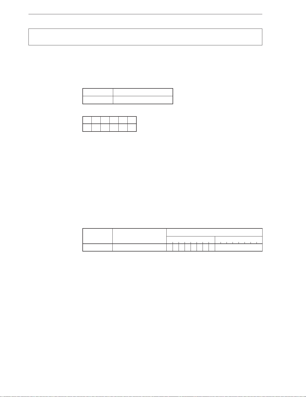
BPO
[Format] BPO short-label
[Operation] Where P = 0: PC ← PC + ext-disp8
[Operand]
[Flag]
[Description] Loads the current PC value with an 8-bit displacement added (actually, sign-extended 16
Mnemonic Operand
BPO short-label
AC CY V P S Z
bits) to the PC if the P flag is 0.
Execution can be branched in a segment where this instruction is placed and in an address
range of –128 to +127 bytes.
Conditional branch where P = 0
Branch if Parity Odd
[Example] ADD AL, BL
BPO SHORT LP14 ; LP14 = label
.
.
.
LP14:
[Number of bytes] 2
[Word format]
Mnemonic Operand
BPO short-label 01111011 disp8
Operation code
7654321076543210
40
Page 52
CHAPTER 2 INSTRUCTIONS
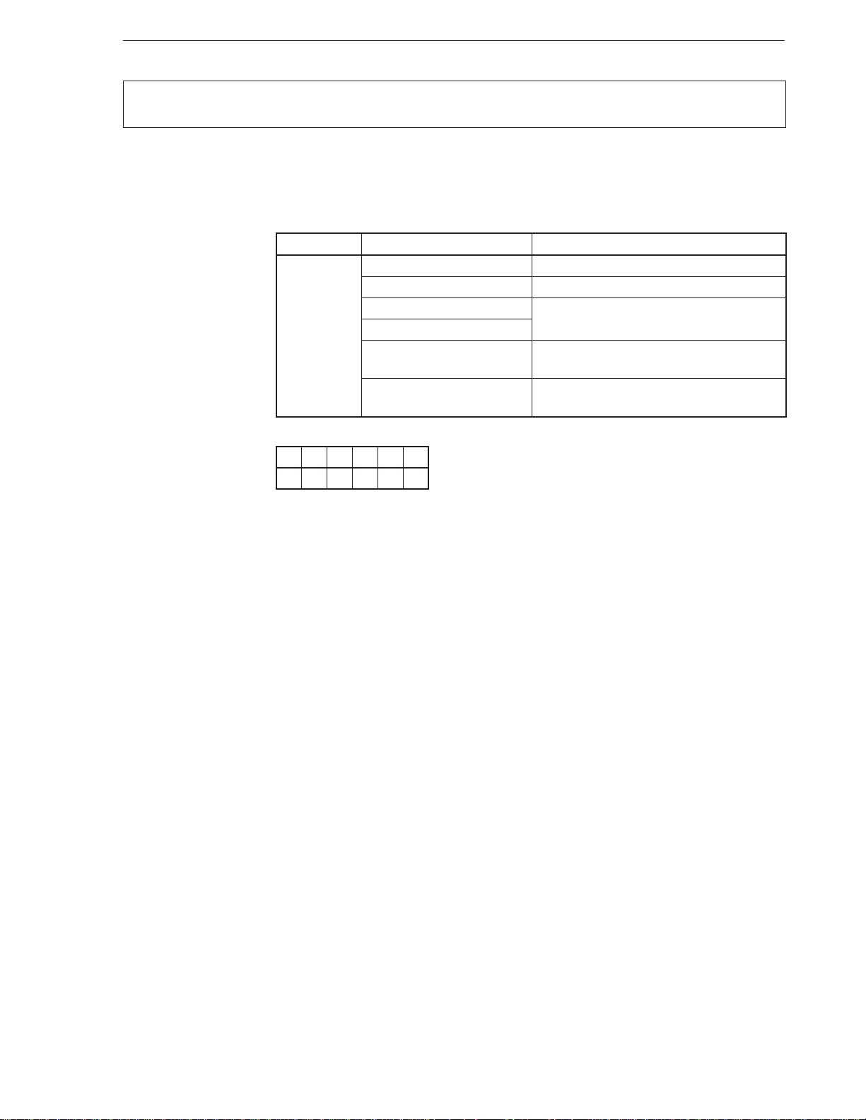
BR
[Format] BR target
[Operation, operand]
Mnemonic Operand (target) Operation
BR near-label PC ← PC + disp
[Flag]
AC CY V P S Z
Unconditional branch
short-label PC ← PC + ext-disp8
regptr16
memptr16
far-label PS ← seg
memptr32 PS ← (memptr32 + 3, memptr32 + 2)
PC ← target
PC ← offset
PC ← (memptr32 + 1, memptr32)
Branch
[Description] • When target = near-label
Transfers the current PC value with a 16-bit displacement (disp) added to the PC.
If the branch address is within a segment where this instruction is placed, the assembler
automatically executes this instruction.
• When target = short-label
Transfers the current PC value with an 8-bit displacement added (actually, signextended 16 bits (ext-disp8)) to the PC.
If the branch address is within a segment where this instruction is placed, and within
a range of ±127 bytes, the assembler automatically executes this instruction.
• When target = regptr16 or target = memptr16
Transfers the contents of the target operand (target) to the PC. Execution can branch
to any address in the segment where this instruction is placed.
• When target = far-label
Transfers the 16-bit offset data at the second and third byte positions of the instruction
to the PC, and the 16-bit segment data at the fourth and fifth byte position of the
instruction to the PS.
Execution can branch to any address of any segment.
• When target = memptr32
Loads the high-order 2 bytes of a 32-bit memory area to the PS, and the low-order 2
bytes, to the PC.
Execution can branch to any address of any segment.
41
Page 53
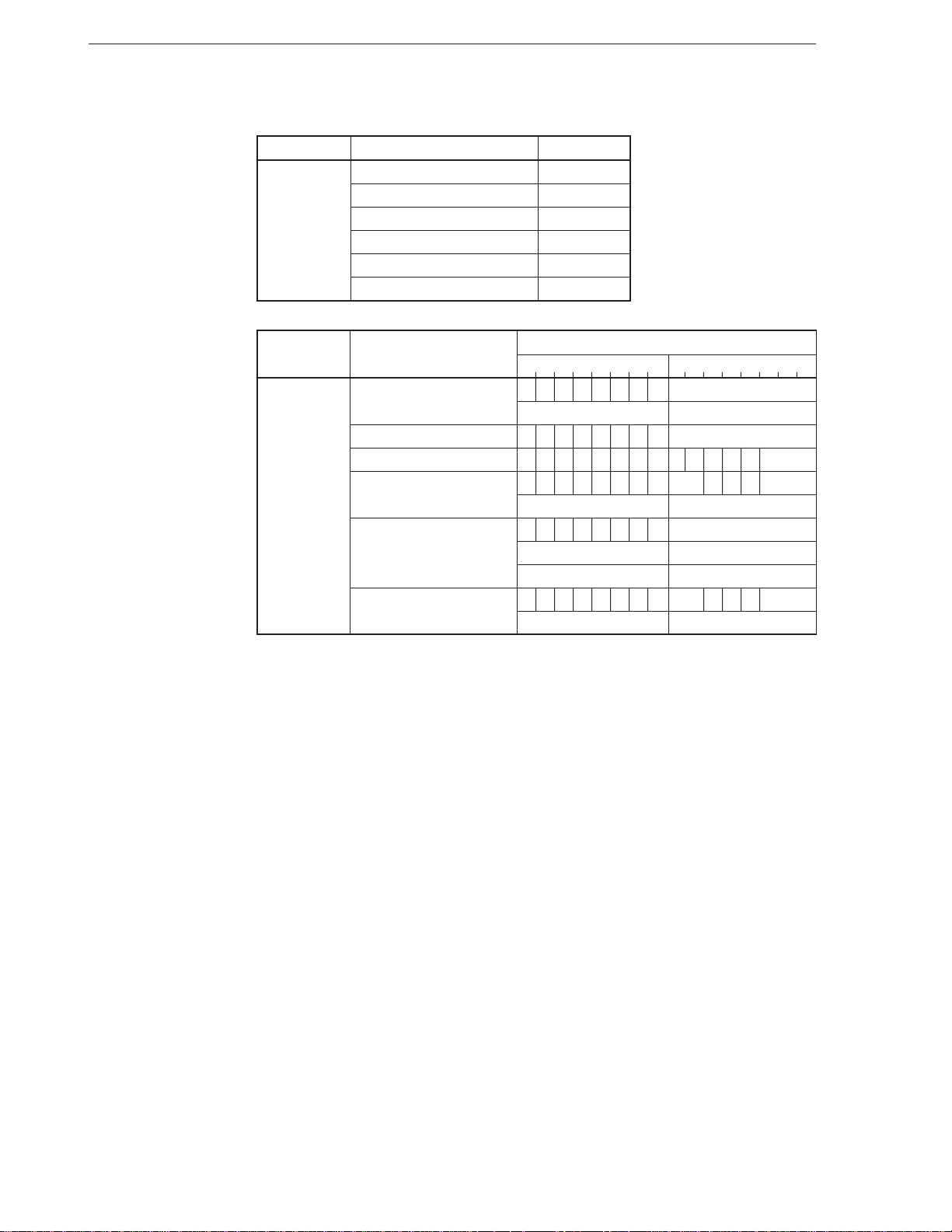
[Example] BR $ – 8
CHAPTER 2 INSTRUCTIONS
[Number of bytes]
[Word format]
Mnemonic Operand No. of bytes
BR near-label 3
short-label 2
regptr16 2
memptr16 2-4
far-label 5
memptr32 2-4
Mnemonic Operand
7654321076543210
BR near-label 11101001 disp-low
disp-high —
short-label 11101011 disp8
regptr16 1111111111100 reg
memptr16 11111111mod100 mem
(disp-low) (disp-high)
far-label 11101010 offset-low
offset-high seg-low
seg-high —
memptr32 11111111mod101 mem
(disp-low) (disp-high)
Operation code
42
Page 54
CHAPTER 2 INSTRUCTIONS
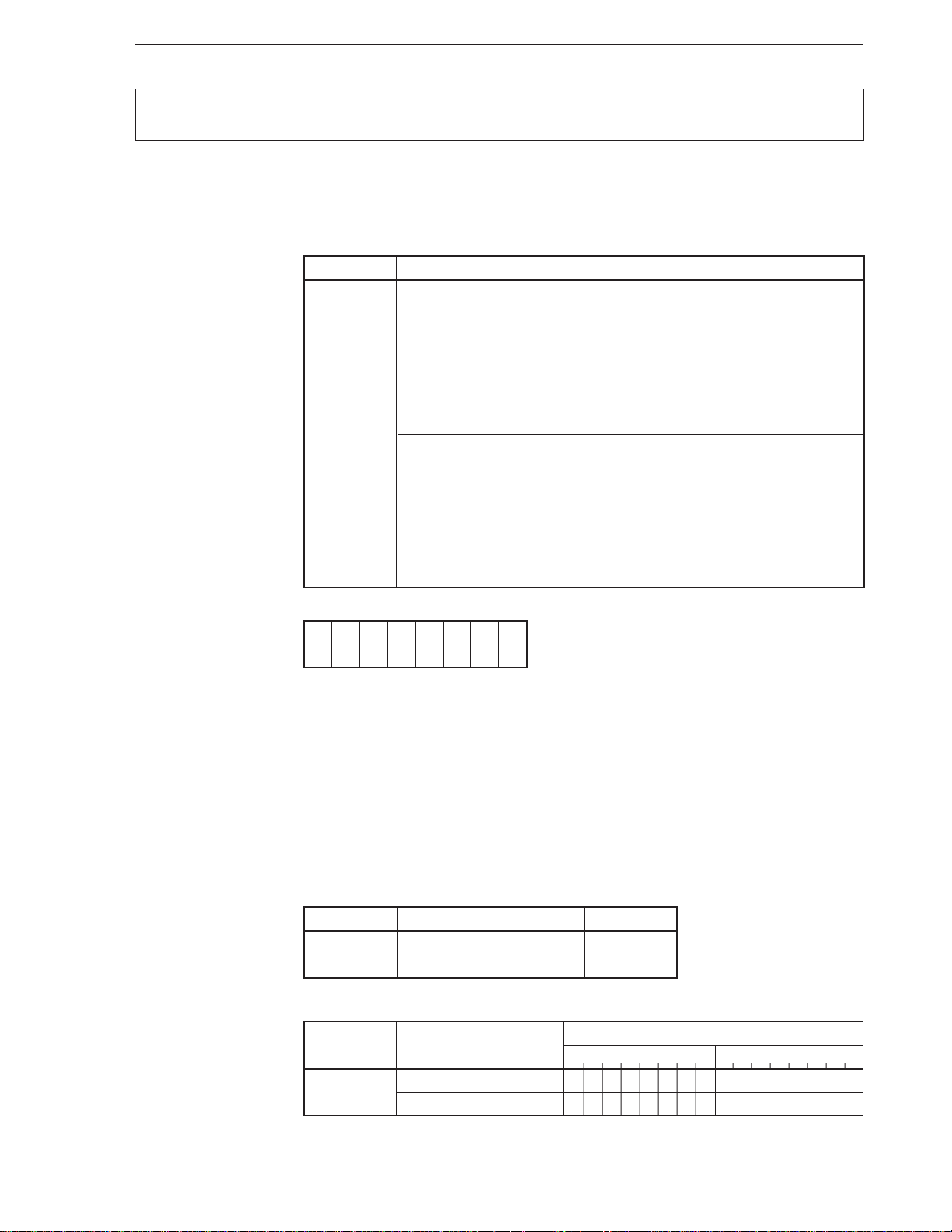
BRK
[Format] BRK target
[Operand, operation]
Mnemonic Operand (target) Operation
BRK 3 TA ← (00DH, 00CH)
Software trap
Break
TC ← (00FH, 00EH)
SP ← SP – 2, (SP + 1, SP) ← PSW
IE ← 0, BRK ← 0
SP ← SP – 2, (SP + 1, SP) ← PS
PS ← TC
SP ← SP – 2, (SP + 1, SP) ← PC
PC ← TA
imm8 (≠ 3) TA ← (imm8 × 4 + 1, imm8 × 4)
TC ← (imm8 × 4 + 3, imm8 × 4 + 2)
SP ← SP – 2, (SP + 1, SP) ← PSW
IE ← 0, BRK ← 0
SP ← SP – 2, (SP + 1, SP) ← PS
PS ← TC
SP ← SP – 2, (SP + 1, SP) ← PC
PC ← TA
[Flag]
AC CY V P S Z IE BRK
00
[Description] Saves the values of PSW, PS, and PC to the stack and resets the IE and BRK flags to 0.
Then loads the low-order 2 bytes of vector 3 in the interrupt vector table to the PC, and
the high-order 2 bytes to the PS if target = 3.
If target = imm8, loads the low-order 2 bytes of the interrupt vector table (4 bits) specified
by the 8-bit immediate data to the PC, and the high-order 2 bytes to the PS.
[Example] • BRK 3
• BRK 5
[Number of bytes]
Mnemonic Operand No. of bytes
BRK 31
imm8 2
[Word format]
Mnemonic Operand
7654321076543210
BRK 3 11001100 —
imm8 11001101 imm8
Operation code
43
Page 55
CHAPTER 2 INSTRUCTIONS
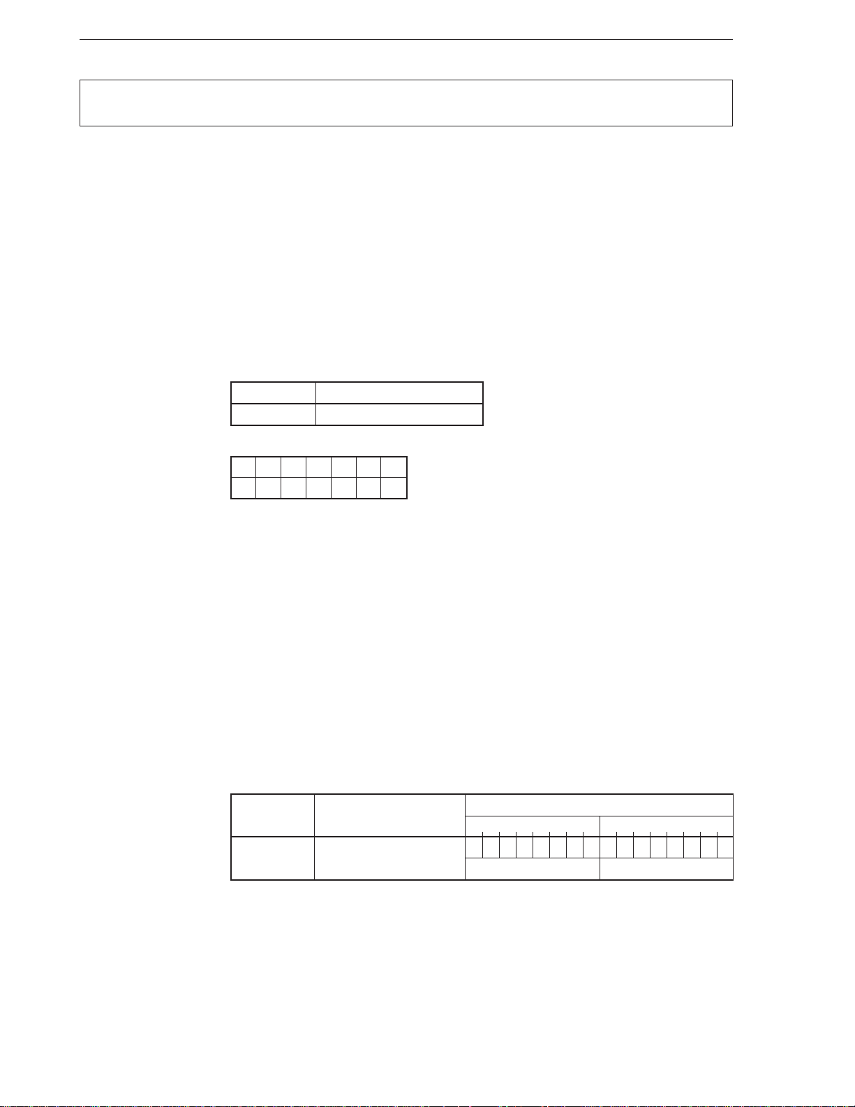
BRKEM
[except V33A and V53A]
[Format] BRKEM imm8
[Operation] TA ← (imm8 × 4 + 1, imm8 × 4)
TC ← (imm8 × 4 + 3, imm8 × 4 + 2)
SP ← SP – 2, (SP + 1, SP) ← PSW
MD ← 0: Write enable status
SP ← SP – 2, (SP + 1, SP) ← PS
PS ← TC
SP ← SP – 2, (SP + 1, SP) ← PC
PC ← TA
[Operand]
[Flag]
Mnemonic Operand
BRKEM imm8
AC CY V P S Z MD
0
Starts emulation mode
Break for Emulation
[Description] This instruction starts the emulation mode. The values of the PSW, PS, and PC are saved
to the stack, the MD flag is reset to 0 to enable writing, and execution jumps to the emulation
address specified by the interrupt vector specified by the 8-bit immediate data described
as an operand.
When the instruction code of the interrupt service routine (for emulation) to which execution
µ
has jumped is fetched, the CPU interprets this code as an instruction of the
PD8080AF
and executes. To return to the native mode from the emulation mode, use the RETEM or
CALLN instruction.
[Example] BRKEM 40H
[Number of bytes] 3
[Word format]
Mnemonic Operand
7654321076543210
BRKEM imm8 0000111111111111
Operation code
imm8 —
44
Page 56
CHAPTER 2 INSTRUCTIONS
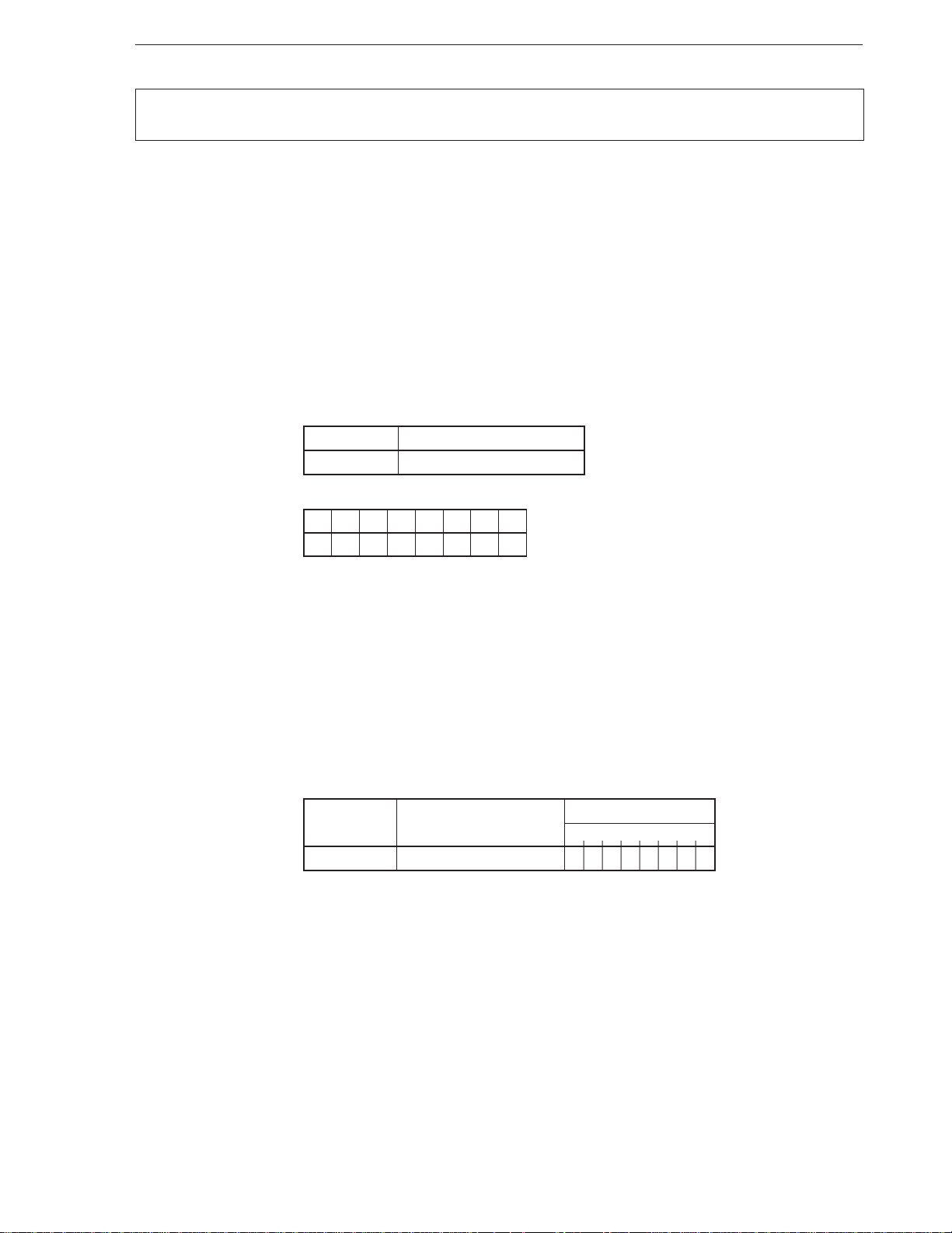
BRKV
[Format] BRKV
[Operation] Where V = 1, TA ← (011H, 010H)
TC ← (013H, 012H)
SP ← SP – 2, (SP + 1, SP) ← PSW
IE ← 0, BRK ← 0
SP ← SP – 2, (SP + 1, SP) ← PS
PS ← TC
SP ← SP – 2, (SP + 1, SP) ← PC
PC ← TA
[Operand]
[Flag]
Mnemonic Operand
BRKV None
AC CY V P S Z IE BRK
00
Overflow exception
Break if Overflow
[Description] Saves the values of PSW, PS, and PC to the stack and resets the IE and BRK flags to 0
if the V flag is set to 1. Then loads the low-order 2 bytes of vector 4 of the interrupt vector
table to the PC and the high-order 2 bytes to the PS if target = 3.
Execution proceeds to the next instruction if the V flag is reset to 0.
[Example] BRKV
[Number of bytes] 1
[Word format]
Mnemonic Operand
BRKV None 11001110
Operation code
76543210
45
Page 57
CHAPTER 2 INSTRUCTIONS
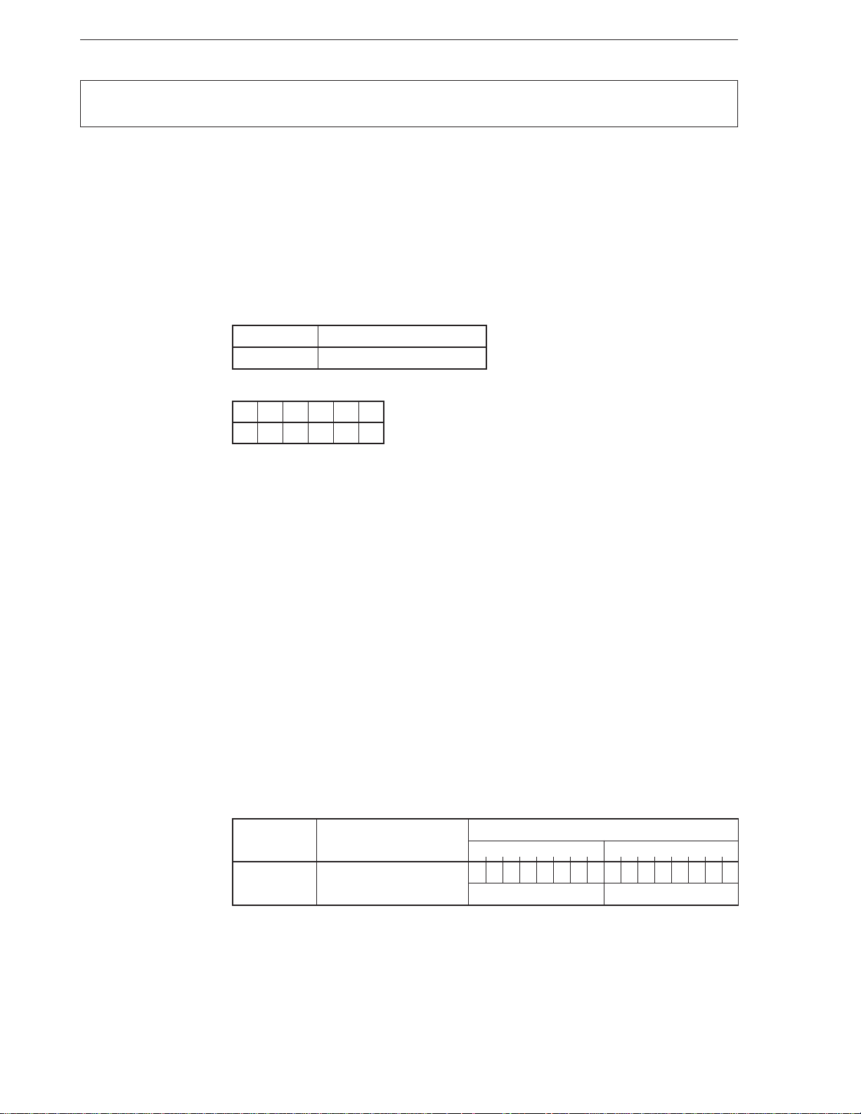
BRKXA
[V33A and V53A only]
Starts extended address mode
Break Extended Address Mode
[Format] BRKXA imm8
[Operation] temp1 ← (imm8 × 4 + 1, imm8 × 4)
temp2 ← (imm8 × 4 + 3, imm8 × 4 + 2)
XA ← 1
PC ← temp1
PS ← temp2
[Operand]
[Flag]
Mnemonic Operand
BRKXA imm8
AC CY V P S Z
[Description] Starts the extended address mode. Transfers control to an address stored to the entry of
the interrupt vector table specified by the operand, and sets the XA flag of the XAM register
(internal I/O address: FF80H) to 1.
If this instruction is executed in the normal address mode, the vector table on the address
in the normal address mode is read and then the extended address mode is set. Execution
jumps to the address of the vector table read first.
If this instruction is executed in the extended address mode, the vector table on the address
in the extended address mode is read, and execution jumps to the address of this vector
table.
The values of PC, PS, and PSW are not saved to the stack. To return from the extended
address mode, use the RETXA instruction. Note that execution cannot be returned from
this mode by the RETI instruction.
[Example] BRKXA 0AH
[Number of bytes] 3
[Word format]
Mnemonic Operand
BRKXA imm8 0000111111100000
46
Operation code
7654321076543210
imm8 —
Page 58
CHAPTER 2 INSTRUCTIONS
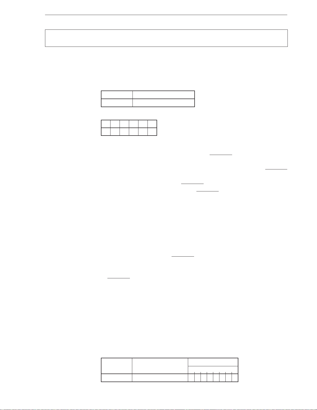
BUSLOCK
[Format] BUSLOCK
[Operation] Bus Lock Prefix
[Operand]
[Flag]
[Description] • V20, V30, V20H, and V30HL
Mnemonic Operand
BUSLOCK None
AC CY V P S Z
In large-scale mode : Outputs the bus lock signal (BUSLOCK) while the single instruction
following this instruction is executed. If this instruction is used
for a block processing instruction with a repeat prefix, the BUSLOCK
signal is continuously output until the block processing is completed.
In small-scale mode: Although the BUSLOCK signal is not output, the bus hold request
is disabled while the BUSLOCK signal is output in the large-scale
mode. Therefore, this instruction is useful for not accepting the
bus hold request during block processing.
Bus lock prefix
Bus Lock Prefix
Cautions 1. Do not place this instruction immediately before the POLL instruction.
2. The hardware interrupt requests (NMI and INT) and single-step break
are not accepted between this instruction and the next instruction.
• Other than V20, V30, V20HL, and V30HL
Outputs the bus lock signal (BUSLOCK) while the single instruction following this
instruction is executed.
If this instruction is used for a block processing instruction with a repeat prefix, the
BUSLOCK signal is continuously output until the block processing is completed.
Cautions 1. Do not place this instruction immediately before the POLL instruction.
2. The hardware interrupt requests (maskable interrupt and non- maskable
interrupt) and single-step break are not accepted between this instruction
and the next instruction.
[Example] BUSLOCK REP MOVBKB
[Number of bytes] 1
[Word format]
Mnemonic Operand
BUSLOCK None 11110000
Operation code
76543210
47
Page 59
CHAPTER 2 INSTRUCTIONS
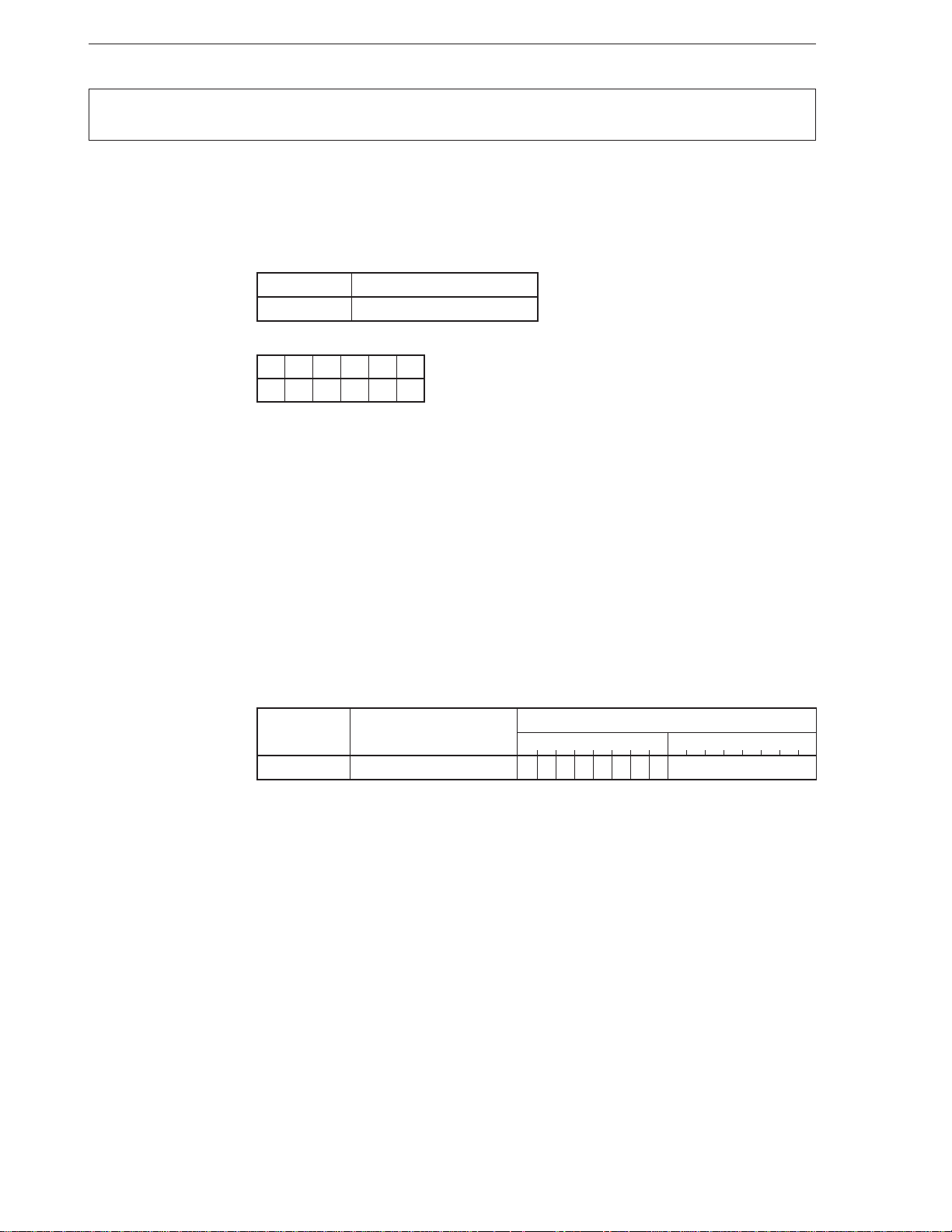
BV
[Format] BV short-label
[Operation] Where V= 1: PC ← PC + ext-disp8
[Operand]
[Flag]
[Description] Loads the current PC value with an 8-bit displacement added (actually, sign-extended 16
Mnemonic Operand
BV short-label
AC CY V P S Z
bits) to the PC when the V flag is 1.
Execution can be branched in a segment where this instruction is placed and in an address
range of –128 to +127 bytes.
Conditional branch where V = 1
Branch if Overflow
[Example] LP2:
[Number of bytes] 2
[Word format]
BV short-label 01110000 disp8
.
.
.
SHL AL, 1
BV SHORT LP2
Mnemonic Operand
Operation code
7654321076543210
48
Page 60
CHAPTER 2 INSTRUCTIONS
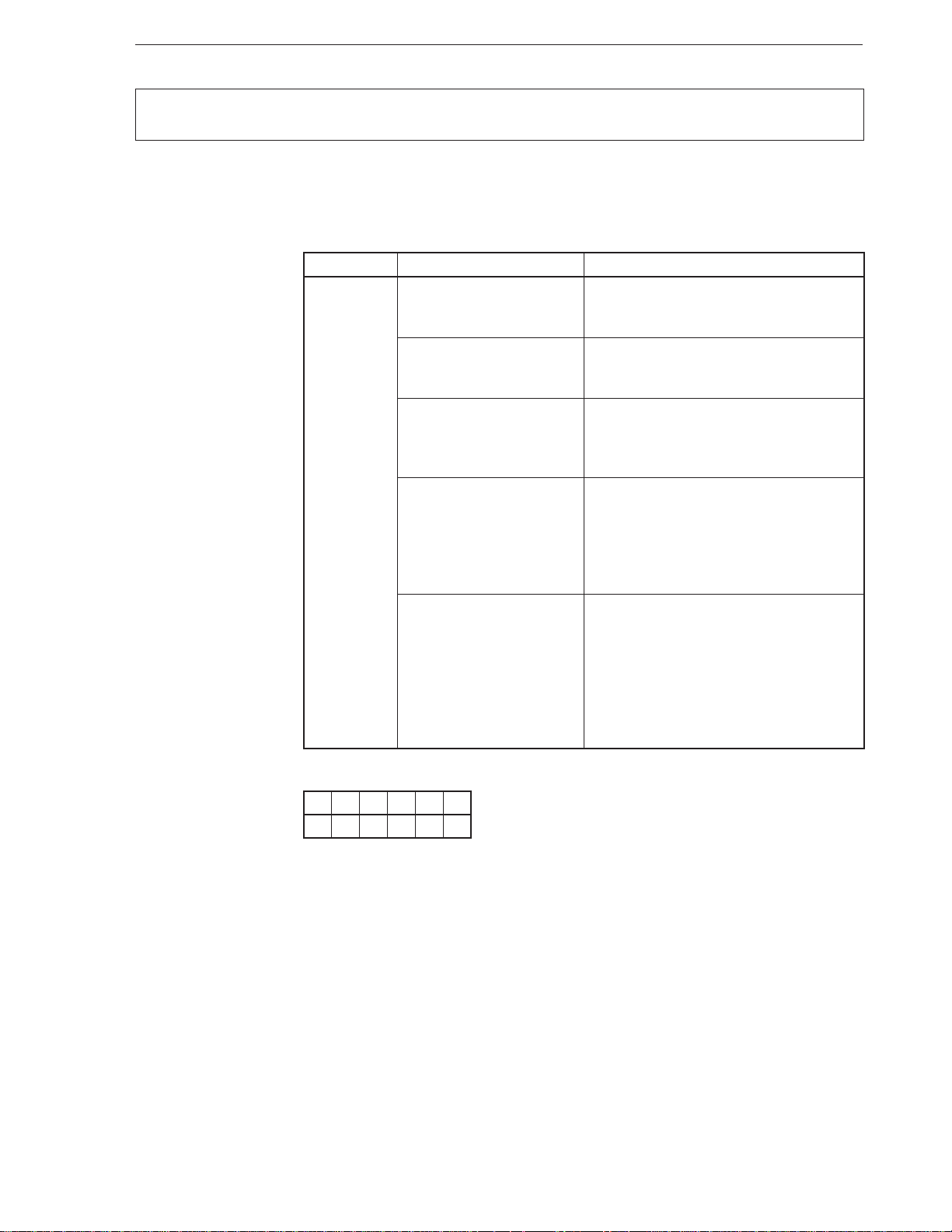
CALL
[Format] CALL target
[Operand, operation]
Mnemonic Operand (target) Operation
CALL near-proc SP ← SP – 2
Subroutine call
Call
(SP + 1, SP) ← PC
PC ← PC + disp
regptr16 SP ← SP – 2
(SP + 1, SP) ← PC
PC ← regptr16
memptr16 TA ← (memptr16 + 1, memptr16)
SP ← SP – 2
(SP + 1, SP) ← PC
PC ← TA
far-proc SP ← SP – 2
(SP + 1, SP) ← PS
PS ← seg
SP ← SP – 2
(SP + 1, SP) ← PC
PS ← offset
memptr32 TA ← (memptr32 + 1, memptr32)
TB ← (memptr32 + 3, memptr32 + 2)
SP ← SP – 2
(SP + 1, SP) ← PS
PS ← TB
SP ← SP – 2
(SP + 1, SP) ← PC
PC ← TA
[Flag]
AC CY V P S Z
[Description] • When target = near-proc or target = regptr16
Saves the value of the PC to the stack and then transfers the next contents of the target
operand (target) to the PC.
When target = near-proc: 16-bit relative address
When target = regptr16 : Value of 16-bit register (offset)
• When target = memptr16
Saves the value of the PC to the stack and then transfers the contents of a 16-bit memory
area (offset) addressed by the target operand (target) to the PC.
Any address in the segment where this instruction is placed can be called.
49
Page 61
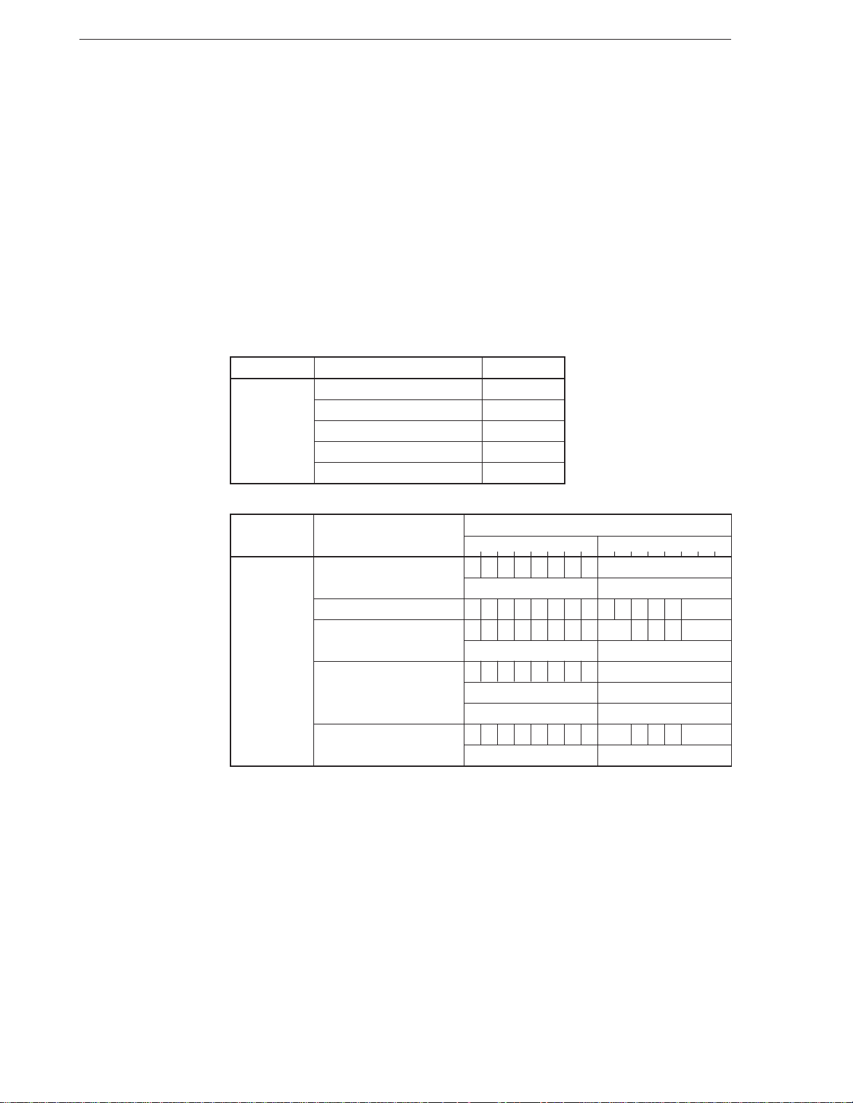
• When target = far-proc
Saves the values of PC and PS to the stack and transfers the second and third bytes
of the instruction to the PC, and the fourth and fifth bytes to the PS.
This instruction can call any address in any segment.
• When target = memptr32
Saves the values of PC and PS to the stack and transfers the high-order 2 bytes of a
32-bit memory area addressed by the target operand (target) to the PS and the loworder 2 bytes to the PC.
This instruction can call any address in any segment.
[Example] • CALL $ + 10
• CALL SUB1 ; SUB1 is label
CHAPTER 2 INSTRUCTIONS
[Number of bytes]
[Word format]
Mnemonic Operand No. of bytes
CALL near-proc 3
regptr16 2
memptr16 2-4
far-proc 5
memptr32 2-4
Mnemonic Operand
7654321076543210
CALL near-proc 11101000 disp-low
disp-high —
regptr16 1111111111010 reg
memptr16 11111111mod010 mem
(disp-low) (disp-high)
far-proc 10011010 offset-low
offset-high seg-low
seg-high —
memptr32 11111111mod011 mem
(disp-low) (disp-high)
Operation code
50
Page 62
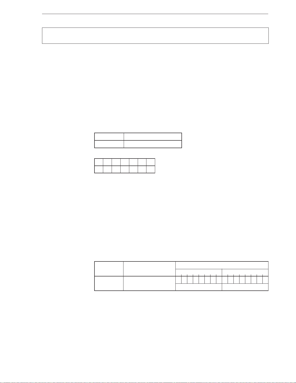
CHAPTER 2 INSTRUCTIONS
CALLN
[except V33A and V53A]
[Format] CALLN imm8
[Operation] TA ← (imm8 × 4 + 1, imm8 × 4)
TC ← (imm8 × 4 + 3, imm8 × 4 + 2)
SP ← SP – 2, (SP + 1, SP) ← PSW
MD ← 1
SP ← SP – 2, (SP + 1, SP) ← PS
PS ← TC
SP ← SP – 2, (SP + 1, SP) ← PC
PC ← TA
[Operand]
[Flag]
Mnemonic Operand
CALLN imm8
AC CY V P S Z MD
1
Native mode call
Call Native
[Description] When this instruction is executed in the emulation mode (this instruction is interpreted as
µ
an instruction of the
PD8080AF), the CPU saves the values of PS, PC, and PSW to the
stack (at this time, MD = 0 is saved), sets the MD flag to 1, and loads an interrupt vector
specified by the 8-bit immediate data described as an operand to the PS and PC.
In this way, an interrupt routine in the native mode can be called from the emulation mode.
To return to the emulation mode from this interrupt routine, use the RETI instruction.
[Example] CALLN 40H
[Number of bytes] 3
[Word format]
Mnemonic Operand
7654321076543210
CALLN imm8 1110110111101101
Operation code
imm8 —
51
Page 63
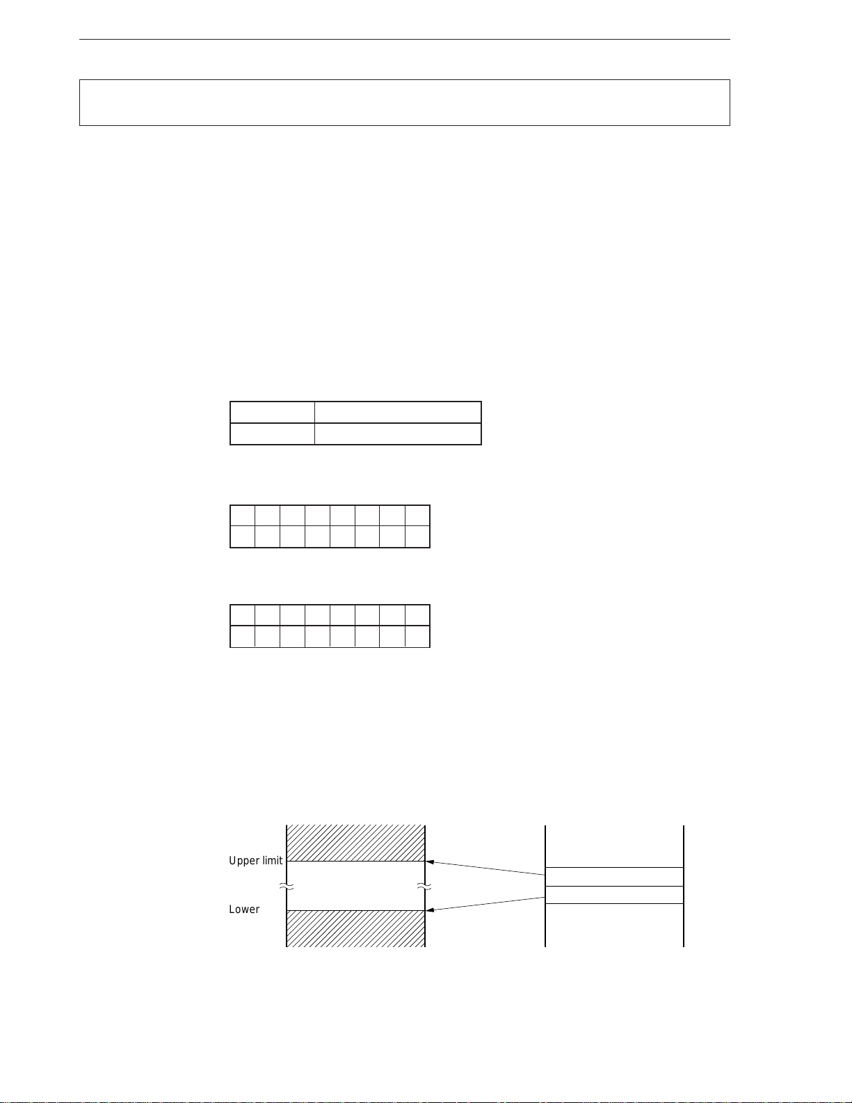
CHAPTER 2 INSTRUCTIONS
CHKIND
[Format] CHKIND reg16, mem32
[Operation] When (mem32) > reg16 or (mem32 + 2) < reg16
TA ← (015H, 014H)
TC ← (017H, 016H)
SP ← SP – 2, (SP + 1, SP) ← PSW
IE ← 0, BRK ← 0
SP ← SP – 2, (SP +1, SP) ← PS
PS ← TC
SP ← SP – 2, (SP + 1, SP) ← PC
PC ← TA
[Operand]
[Flag] If interrupt condition is satisfied
Mnemonic Operand
CHKIND reg16, mem32
Index value check
Check Index
AC CY V P S Z IE
BRK
00
If interrupt condition is not satisfied
AC CY V P S Z IE
BRK
[Description] This instruction checks whether an index value that specifies an element is in a defined
area if the data structure is of array type. If the index exceeds the defined area, the BRK
5 instruction is started. The defined area value is set to 2 words in memory in advance (the
first word is the lower-limit value and the second word is the higher-limit value).
As the index value, the register (any 16-bit register) used by an array manipulation program
is used.
Memory
Upper limit
Array element
Lower limit
15 0
mem32+2
mem32
(Upper limit)
(Lower limit)
52
Page 64

CHAPTER 2 INSTRUCTIONS
[Example] CHKIND AW, DWORD_VAR
[Number of bytes] 2 to 4
[Word format]
Mnemonic Operand
7654321076543210
CHKIND reg16, mem32 01100010mod reg mem
(disp-low) (disp-high)
Operation code
53
Page 65
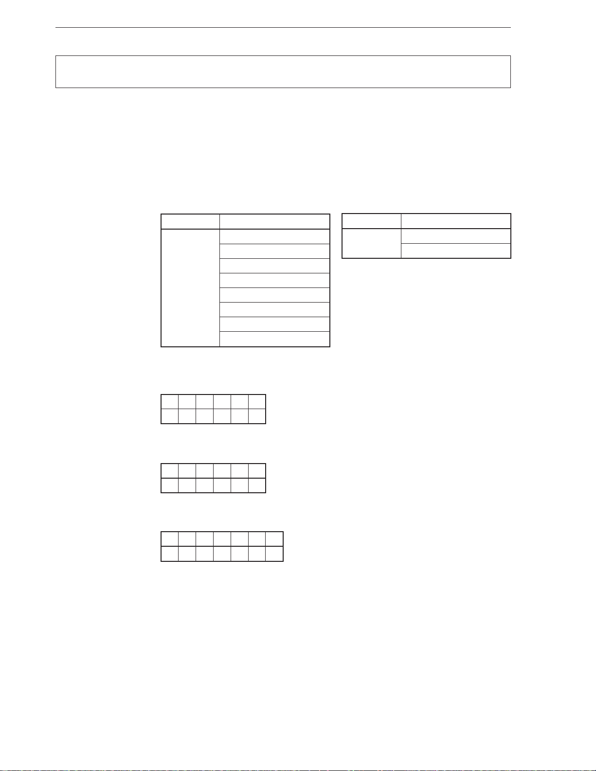
CHAPTER 2 INSTRUCTIONS
CLR1
[Format] (1) CLR1 dst, src
(2) CRL1 dst
[Operation] Format (1): Bit n of dst (n is specified by src) ← 0
Format (2): dst ← 0
[Operand] Format (1) Format (2)
Mnemonic Operand (dst, src)
CLR1 reg8, CL
mem8, CL
reg16, CL
mem16, CL
reg8, imm3
mem8, imm3
reg16, imm4
mem16, imm4
Mnemonic Operand (dst)
CLR1 CY
Resets bit
Clear bit
DIR
[Flag] Format (1)
AC CY V P S Z
Format (2) (when dst = CY)
AC CY V P S Z
0
Format (2) (when dst = DIR)
AC CY V P S Z DIR
0
54
Page 66

CHAPTER 2 INSTRUCTIONS
[Description] Format (1) : Resets bit n (n is the contents of the source operand (src) specified by the
second operand) of the destination operand (dst) specified by the first
operand, and stores the result to the destination operand (dst).
If the operand is reg8, CL or mem8, CL, only the low-order 3 bits (0 to 7) of
the value of CL are valid.
If the operand is reg16, CL or mem16, CL, only the low-order 4 bits (0 to 15)
of the value of CL are valid.
If the operand is reg8, imm3, only the low-order 3 bits of the immediate data
at the fourth byte position of the instruction are valid.
If the operand is mem8, imm3, only the low-order 3 bits of the immediate data
at the last byte position of the instruction are valid.
If the operand is reg16, imm4, only the low-order 4 bits of the immediate data
at the fourth byte position of the instruction are valid.
If the operand is mem16, imm4, only the low-order 4 bits of the immediate
data at the last byte of the instruction are valid.
Format (2) : Resets the CY flag if dst = CY.
Resets the DIR flag if dst = DIR. Also sets so that the index registers (IX and
IY) are auto-incremented when MOVBK, CMPBK, CMPM, LDM, STM, INM,
or OUTM instruction is executed.
[Example] CLR1 CY
SHL AL,1
BC $ + 6
[Number of bytes]
Mnemonic Operand No. of bytes
CLR1 reg8, CL 3
mem8, CL 3-5
reg16, CL 3
mem16, CL 3-5
reg8, imm3 4
mem8, imm3 4-6
reg16, imm4 4
mem16, imm4 4-6
CY 1
DIR 1
55
Page 67
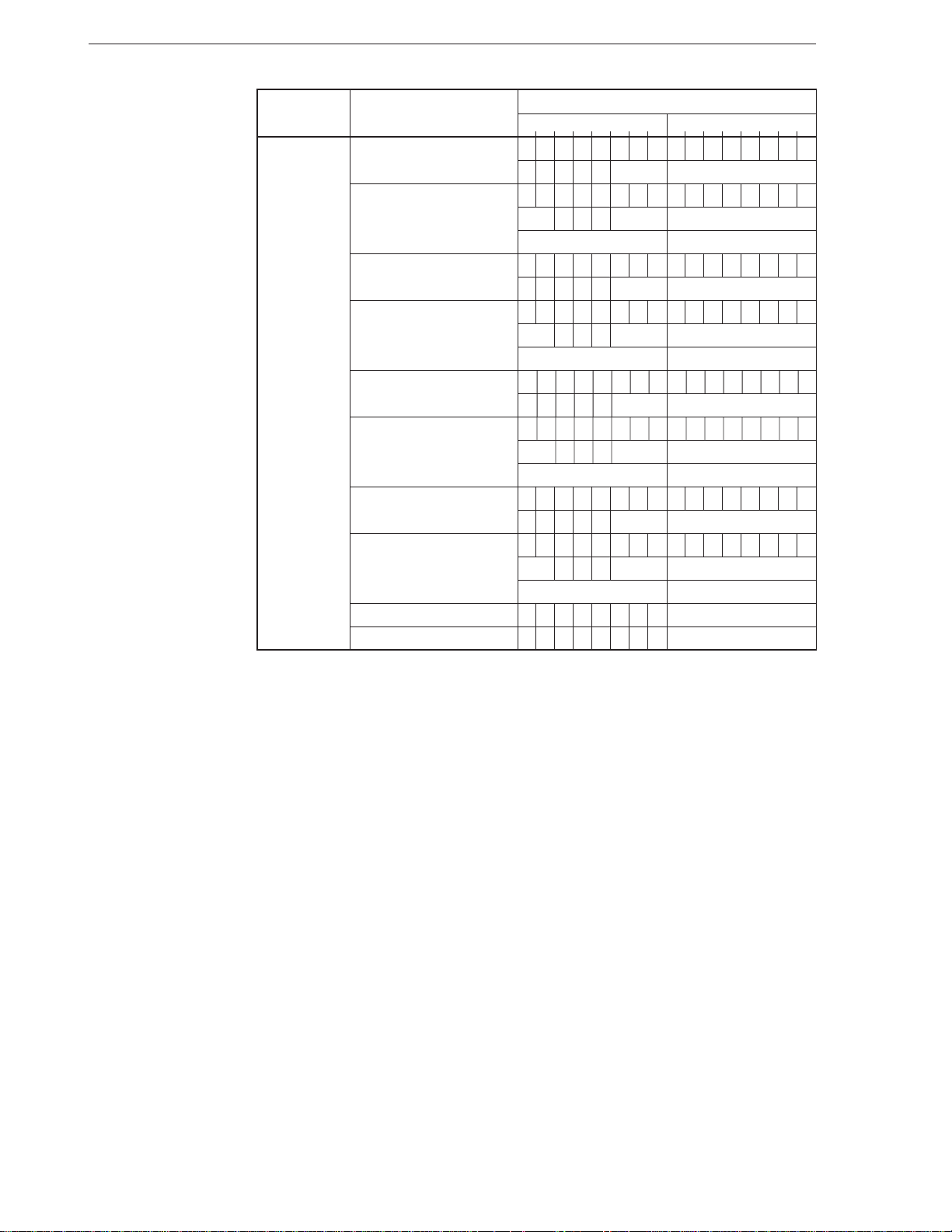
CHAPTER 2 INSTRUCTIONS
[Word format]
Mnemonic Operand
7654321076543210
CLR1 reg8, CL 0000111100010010
11000 reg —
mem8, CL 0000111100010010
mod 0 0 0 mem (disp-low)
(disp-high) —
reg16, CL 0000111100010011
11000 reg —
mem16, CL 0000111100010011
mod 0 0 0 mem (disp-low)
(disp-high) —
reg8, imm3 0000111100011010
11000 reg imm3
mem8, imm3 0000111100011010
mod 0 0 0 mem (disp-low)
(disp-high) imm3
reg16, imm4 0000111100011011
11000 reg imm4
mem16, imm4 0000111100011011
mod 0 0 0 mem (disp-low)
(disp-high) imm4
CY 11111000 —
DIR 11111100 —
Operation code
56
Page 68
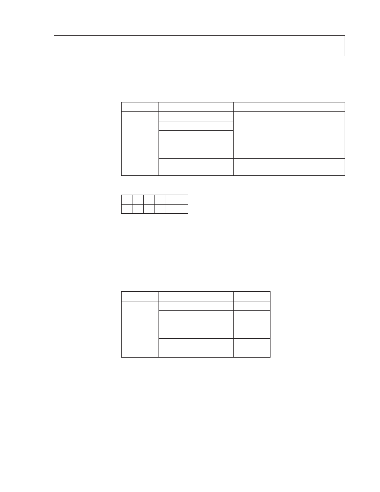
CHAPTER 2 INSTRUCTIONS
CMP
[Format] CMP dst, src
[Operand, operation]
Mnemonic Operand (dst, src) Operation
CMP reg, reg’ dst – src
[Flag]
AC CY V P S Z
ЧЧЧЧЧЧ
Compare
Compare
mem, reg
reg, mem
reg, imm
mem, imm
acc, imm [When W = 0] AL – imm8
[When W = 1] AW – imm16
[Description] Subtracts the source operand (src) specified by the second operand from the destination
operand (dst) specified by the first operand.
The result of the subtraction is stored nowhere, and only the flags are affected.
[Example] • CMP BL, BYTE PTR [IX]
• CMP CW, [BP+4]
[Number of bytes]
Mnemonic Operand No. of bytes
CMP reg, reg’ 2
mem, reg 2-4
reg, mem
reg, imm 3, 4
mem, imm 3-6
acc, imm 2, 3
57
Page 69
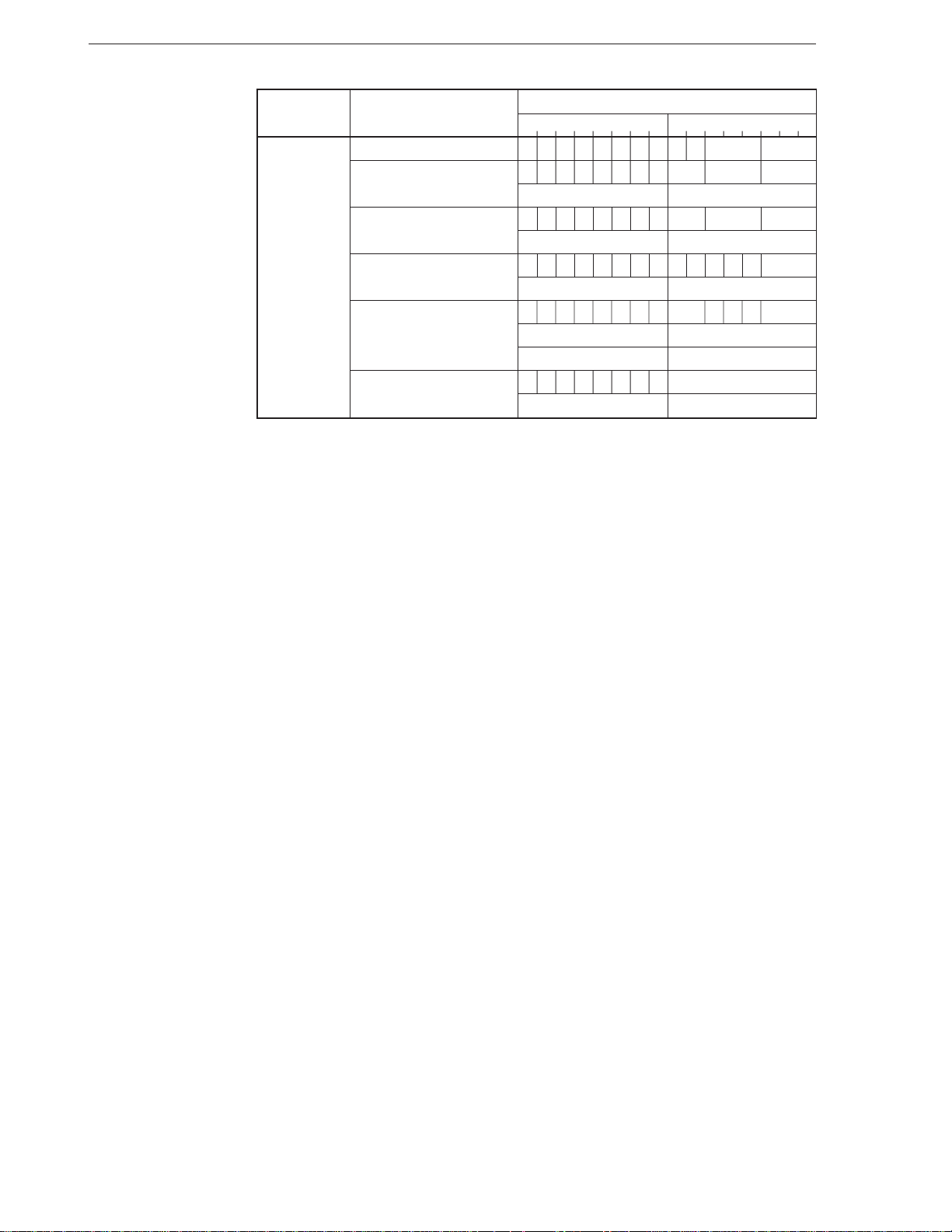
CHAPTER 2 INSTRUCTIONS
[Format]
Mnemonic Operand
7654321076543210
CMP reg, reg’ 0011101W11 reg reg‘
mem, reg 0011100Wmod reg mem
(disp-low) (disp-high)
reg, mem 0011101Wmod reg mem
(disp-low) (disp-high)
reg, imm 100000sW11111 reg
imm8 or imm16-low imm16-high
mem, imm 100000sWmod111 mem
(disp-low) (disp-high)
imm8 or imm16-low imm16-high
acc, imm 0011110W imm8 or imm16-low
imm16-high —
Operation code
58
Page 70
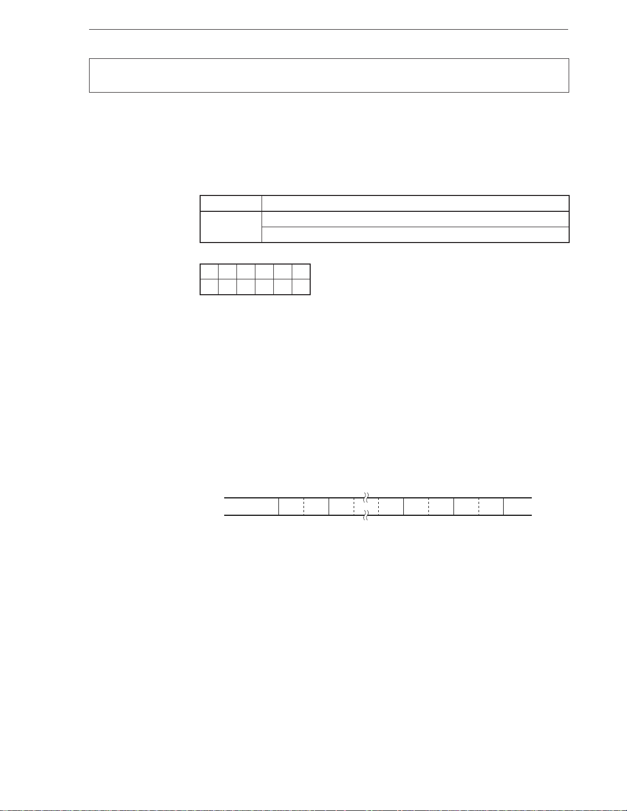
CHAPTER 2 INSTRUCTIONS
CMP4S
Compare Nibble String
[Format] CMP4S [DS1-spec:] dst-string, [Seg-spec:] src-string
CMP4S
[Operation] BCD string (IY, CL) ← BCD string (IX, CL)
Decimal compare
[Operand]
[Flag]
Mnemonic Operand (dst, src)
CMP4S [DS1-spec : ] dst-string, [Seg-spec : ] src-string
None
AC CY V P S Z
U × UUU×
[Description] Subtracts the packed BCD string addressed by the IX register from the packed BCD string
addressed by the IY register. The result is not stored and only the flags are affected. The
string length (number of BCD digits) is determined by the CL register (the number of digits
is d if the contents of CL is d) in a range of 1 to 254 digits.
The destination string must be always located in a segment specified by the DS1 register,
and the segment cannot be overridden. Although the default segment register of the source
string is the DS0 register, the segment can be overridden, and the string can be located
in a segment specified by any segment register. The format of a packed BCD string is as
follows.
Byte offset
Memory
Digit offset
+m
+CL 0+1+2+3+4
+0+1
IX
IY
↓
Caution The BCD string instruction always operates in units of an even number of
digits. If an even number of digits is specified, therefore, the result of the
operation and each flag operation are normal. If an odd number of digits
is specified, however, an operation of an even number of digits, or an odd
number of digits + 1, is executed. As a result, the result of the operation
is an even number of digits and each flag indicates an even number of
digits.
To specify an odd number of digits, therefore, keep this in mind: Execute
the BCD compare instruction, if the number of digits is odd, after clearing
the high-order 4 bits of the most significant byte to “0”.
59
Page 71
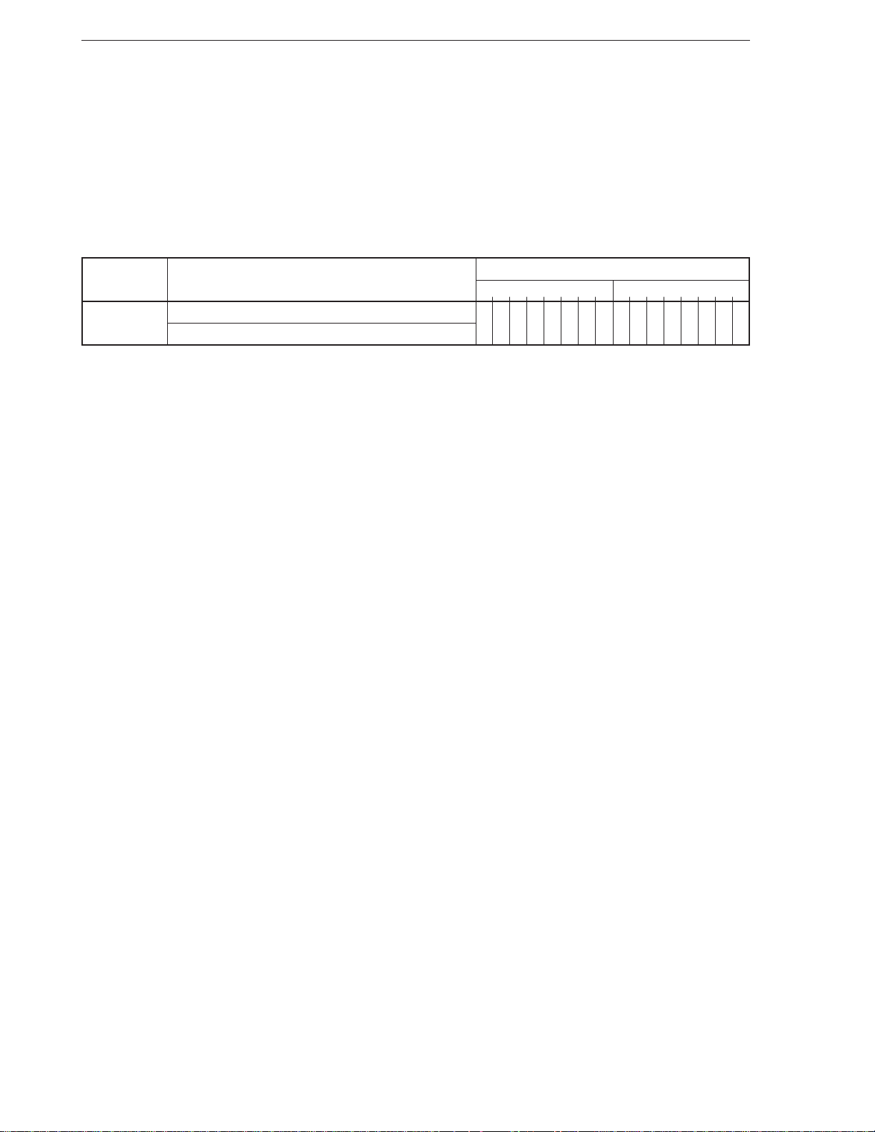
CHAPTER 2 INSTRUCTIONS
[Example] MOV IX, OFFSET VAR_1
MOV IY, OFFSET VAR_2
MOV CL, 4
CMP4S
[Number of bytes] 2
[Word format]
Mnemonic Operand
7654321076543210
CMP4S [DS1-spec : ] dst-string, [Seg-spec : ] src-string 0000111100100110
None
Operation code
60
Page 72
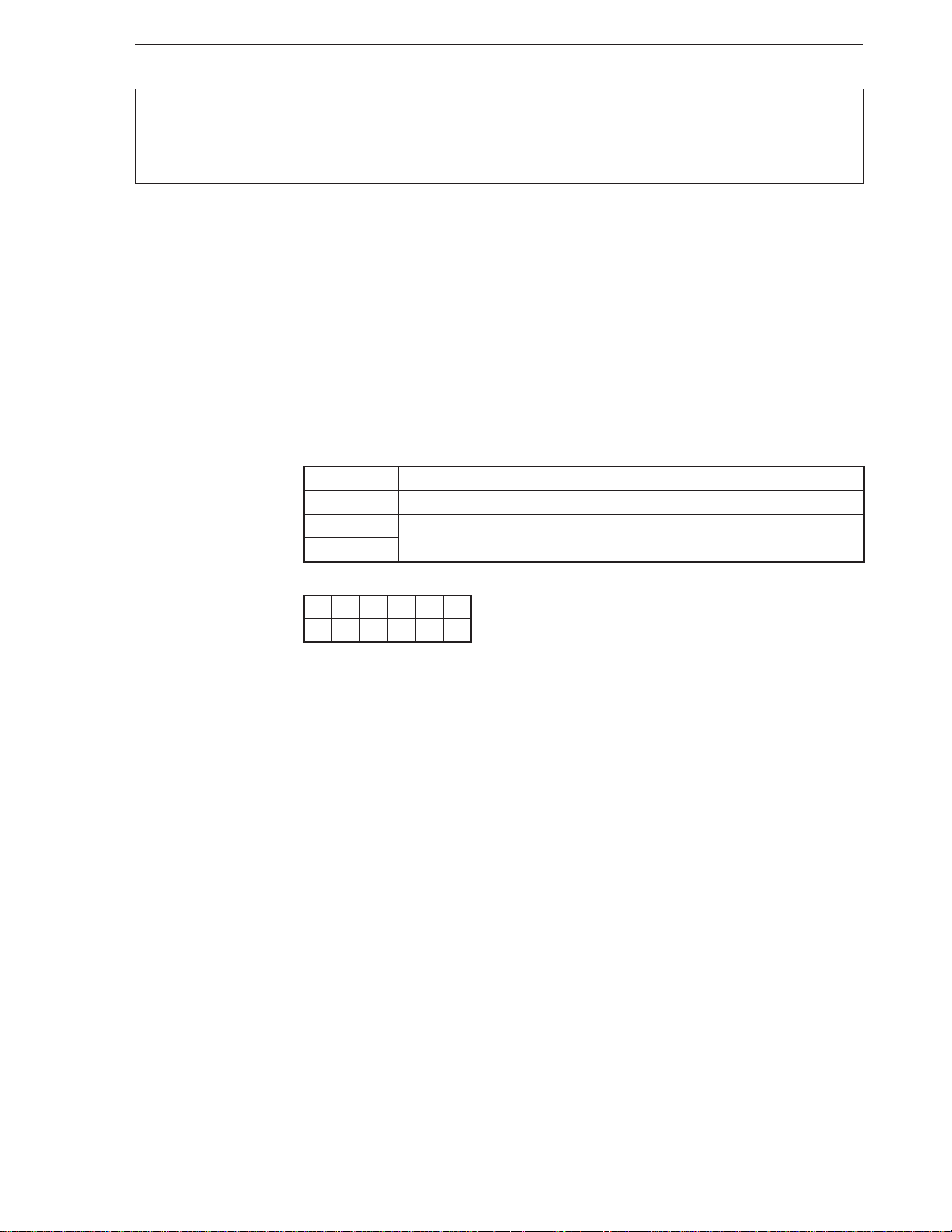
CHAPTER 2 INSTRUCTIONS
CMPBK
CMPBKB
Block compare
Compare Block
Compare Block Byte
CMPBKW Compare Block Word
[Format] (repeat) CMPBK [Seg-spec:] src-block, [DS1-spec:] dst- block
(repeat) CMPBKB
(repeat) CMPBKW
[Operation] [When W = 0] (IX) – (IY)
DIR = 0: IX ← IX + 1, IY ← IY + 1
DIR = 1: IX ← IX – 1, IY ← IY – 1
[When W = 1] (IX + 1, IX) – (IY + 1, IY)
DIR = 0: IX ← IX + 2, IY ← IY + 2
DIR = 1: IX ← IX – 2, IY ← IY – 2
[Operand]
Mnemonic Operand
CMPBK [Seg-spec : ] src-block, [DS1-spec : ] dst-block
CMPBKB None
CMPBKW
[Flag]
[Description] Repeatedly subtracts the block addressed by the IY register from the block addressed by
[Example] CMPBK BYTE_VAR1, BYTE_VAR2
[Number of bytes] 1
AC CY V P S Z
ЧЧЧЧЧЧ
the IX register in byte or word units, and reflects the result on the flags.
The IX and IY registers are automatically incremented (+1/+2) or decremented (–1/–2) for
the next byte/word processing each time data of 1 byte/word has been processed. The
direction of the block is determined by the status of the DIR flag.
Whether data is processed in byte or word units is specified by the attribute of the operand
when the CMPBK instruction is used. When the CMPBKB and CMPBKW instructions are
used, the data is processed in byte and word units, respectively.
The destination block must be always located in a segment specified by the DS1 register,
and the segment cannot be overridden. On the other hand, although the default segment
register of the source block is the DS0 register, the segment can be overridden, and the
block can be located in a segment specified by any segment register.
61
Page 73
CHAPTER 2 INSTRUCTIONS
[Word format]
Mnemonic Operand
CMPBK [Seg-spec : ] src-block, [DS1-spec : ] dst-block 1010011W
CMPBKB None
CMPBKW
Operation code
76543210
62
Page 74

CHAPTER 2 INSTRUCTIONS
CMPM
CMPMB
Block compare with accumulator
Compare Multiple
Compare Multiple Byte
CMPMW Compare Multiple Word
[Format] (repeat) CMPM [DS1-spec:] dst-block
(repeat) CMPMB
(repeat) CMPMW
[Operation] [When W = 0] AL – (IY)
DIR = 0: IY ← IY + 1
DIR = 1: IY ← IY – 1
[When W = 1] AW – (IY + 1, IY)
DIR = 0: IY ← IY + 2
DIR = 1: IY ← IY – 2
[Operand]
Mnemonic Operand
CMPM [DS1-spec : ] dst-block
CMPMB None
CMPMW
[Flag]
[Description] Repeatedly subtracts the block addressed by the IY register from the value of the
[Example] • MOV AW, 5555H
AC CY V P S Z
ЧЧЧЧЧЧ
accumulator (AL/AW) in byte or word units, and reflects the result on the flags.
The IY register is automatically incremented (+1/+2) or decremented (–1/–2) for the next
byte/word processing each time data of 1 byte/word has been processed. The direction
of the block is determined by the status of the DIR flag.
Whether data is processed in byte or word units is specified by the attribute of the operand
when the CMPM instruction is used. When the CMPMB and CMPMW instructions are used,
the data is processed in byte and word units, respectively.
The destination block must be always located in a segment specified by the DS1 register,
and the segment cannot be overridden.
MOV BW, 1000H
MOV IY, BW
REPC CMPM WORD PTR [IY]
• REPNC CMPMW
• REPZ CMPMB
[Number of bytes] 1
63
Page 75
CHAPTER 2 INSTRUCTIONS
[Word format]
Mnemonic Operand
CMPM [DS1-spec : ] dst-block 1010111W
CMPMB None
CMPMW
Operation code
76543210
64
Page 76
CHAPTER 2 INSTRUCTIONS
CVTBD
Convert Binary to Decimal
[Format] CVTBD
[Operation] AH ← AL ÷ 0AH
AL ← AL%0AH
Binary-to-unpacked decimal conversion
[Operand]
[Flag]
Mnemonic Operand
CVTBD None
AC CY V P S Z
UUU×××
[Description] Converts the 8-bit binary number of the AL register into a 2- digit unpacked decimal number.
As a result, the value of the AH register is replaced with the quotient resulting from dividing
the value of the AL register by 10, and then the value of the AL register is replaced with
the remainder resulting from the division.
[Example] MOV AL, 30H
CVTBD
[Number of bytes] 2
[Word format]
Mnemonic Operand
CVTBD None 1101010000001010
Operation code
7654321076543210
65
Page 77
CHAPTER 2 INSTRUCTIONS
CVTBW
[Format] CVTBW
[Operation] When AL < 80H: AH ← 0
When AL ≥ 80H: AH ← FFH
[Operand]
[Flag]
[Description] Extends the sign of the byte in the AL register to the AH register. This instruction is useful
Mnemonic Operand
CVTBW None
AC CY V P S Z
for obtaining a double- length dividend (word) from a certain byte before executing byte
division.
Word sign extension
Convert Byte to Word
[Example] MOV AL, BUF1; BUF1 is byte variable
CVTBW
MOV DL, 60
DIV DL
[Number of bytes] 1
[Word format]
Mnemonic Operand
CVTBW None 10011000
Operation code
76543210
66
Page 78
CHAPTER 2 INSTRUCTIONS
CVTDB
Convert Decimal to Binary
[Format] CVTDB
[Operation] AL ← AH × 0AH + AL
AH ← 0
Unpacked decimal-to-binary conversion
[Operand]
[Flag]
Mnemonic Operand
CVTDB None
AC CY V P S Z
UUU×××
[Description] Converts the 2-digit unpacked decimal number of the AH and AL registers into a 16-bit
binary number.
As a result, the value of the AL register is replaced with the sum of value of the AL register
and the result of multiplying the value of the AH register by 10, and the value of the AH
register is replaced with 0.
[Example] MOV AW, [BW]
CVTDB
[Number of bytes] 2
[Word format]
Mnemonic Operand
CVTDB None 1101010100001010
Operation code
7654321076543210
67
Page 79
CHAPTER 2 INSTRUCTIONS
CVTWL
[Format] CVTWL
[Operation] When AW < 8000H: DW ← 0
When AW ≥ 8000H: DW ← FFFFH
[Operand]
[Flag]
[Description] Extends the sign of the word of the AW register to the DW register. This instruction is useful
Mnemonic Operand
CVTWL None
AC CY V P S Z
for obtaining a double-length (double word) dividend from a certain word before executing
word division.
Double word sign extension
Convert Word to Long Word
[Example] MOV AW, BUFFER
CVTWL
DIV CW
[Number of bytes] 1
[Word format]
Mnemonic Operand
CVTWL None 10011001
Operation code
76543210
68
Page 80
CHAPTER 2 INSTRUCTIONS
DBNZ
[Format] DBNZ short-label
[Operation] CW ← CW – 1
Where CW ≠ 0: PC ← PC + ext-disp8
[Operand]
[Flag]
[Description] Decrements the value of the CW register (–1) and, if the value of the CW register is not
Mnemonic Operand
DBNZ short-label
AC CY V P S Z
zero as a result, loads the current PC value with an 8-bit displacement added (actually,
sign-extended 16 bits) to the PC.
Execution can branch in the segment where this instruction is placed and in an address
range of –128 to +127 bytes. Execution goes on to the next instruction if the above condition
is not satisfied.
Conditional loop where CW ≠ 0
Decrement and Branch if Not Zero
[Example] LP21:
[Number of bytes] 2
[Word format]
Mnemonic Operand
DBNZ short-label 11100010 disp8
.
.
.
SHL AL, 1
DBNZ LP21 ; LP21 = label
Operation code
7654321076543210
69
Page 81
CHAPTER 2 INSTRUCTIONS
DBNZE
[Format] DBNZE short-label
[Operation] CW ← CW – 1
Where CW ≠ 0 and Z = 1: PC ← PC + ext-disp8
[Operand]
[Flag]
[Description] Decrements the value of the CW register (–1) and, if the value of the CW register is not
Mnemonic Operand
DBNZE short-label
AC CY V P S Z
zero and the Z flag is set to 1 as a result, loads the current PC value with an 8-bit
displacement added (actually, sign-extended 16 bits) to the PC.
Execution can branch in the segment where this instruction is placed and in an address
range of –128 to +127 bytes.
Execution goes on to the next instruction if the above condition is not satisfied.
Conditional loop where CW ≠ 0 and Z = 1
Decrement and Branch if Not Zero and Equal
[Example] LP20:
[Number of bytes] 2
[Word format]
Mnemonic Operand
DBNZE short-label 11100001 disp8
.
.
.
AND AL, BL
DBNZE LP20 ; LP20 = label
Operation code
7654321076543210
70
Page 82
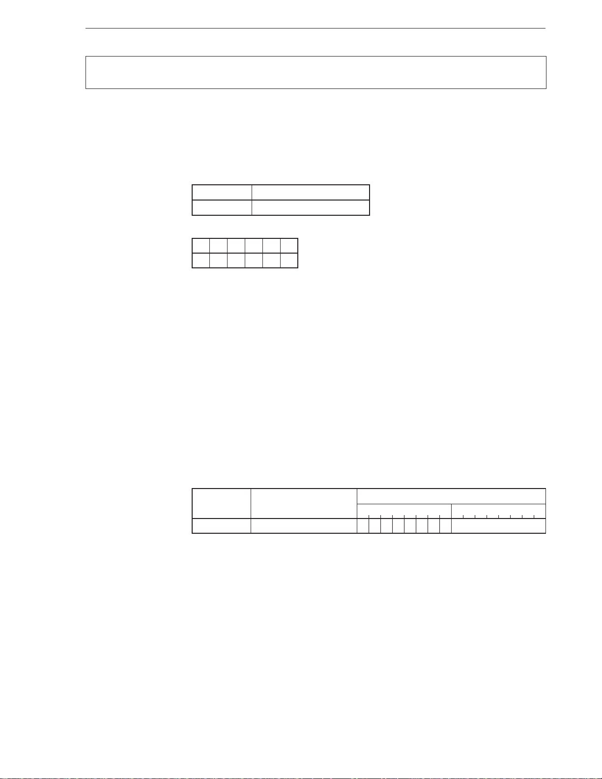
CHAPTER 2 INSTRUCTIONS
DBNZNE
[Format] DBNZNE short-label
[Operation] CW ← CW – 1
Where CW ≠ 0: PC ← PC + ext-disp8
[Operand]
[Flag]
[Description] Decrements the value of the CW register (–1) and, if the value of the CW register is not
Mnemonic Operand
DBNZNE short-label
AC CY V P S Z
zero and the Z flag is cleared as a result, loads the current PC value with an 8-bit
displacement added (actually, sign-extended 16 bits) to the PC.
Execution can branch in the segment where this instruction is placed and in an address
range of –128 to +127 bytes.
Execution goes on to the next instruction if the above condition is not satisfied.
Decrement and Branch if Not Zero and Not Equal
Conditional loop where CW ≠ 0 and Z = 0
[Example] LP19:
[Number of bytes] 2
[Word format]
Mnemonic Operand
DBNZNE short-label 11100000 disp8
.
.
.
AND AL, 0FFH
DBNZNE SHORT LP19 ; LP19 = label
7654321076543210
Operation code
71
Page 83
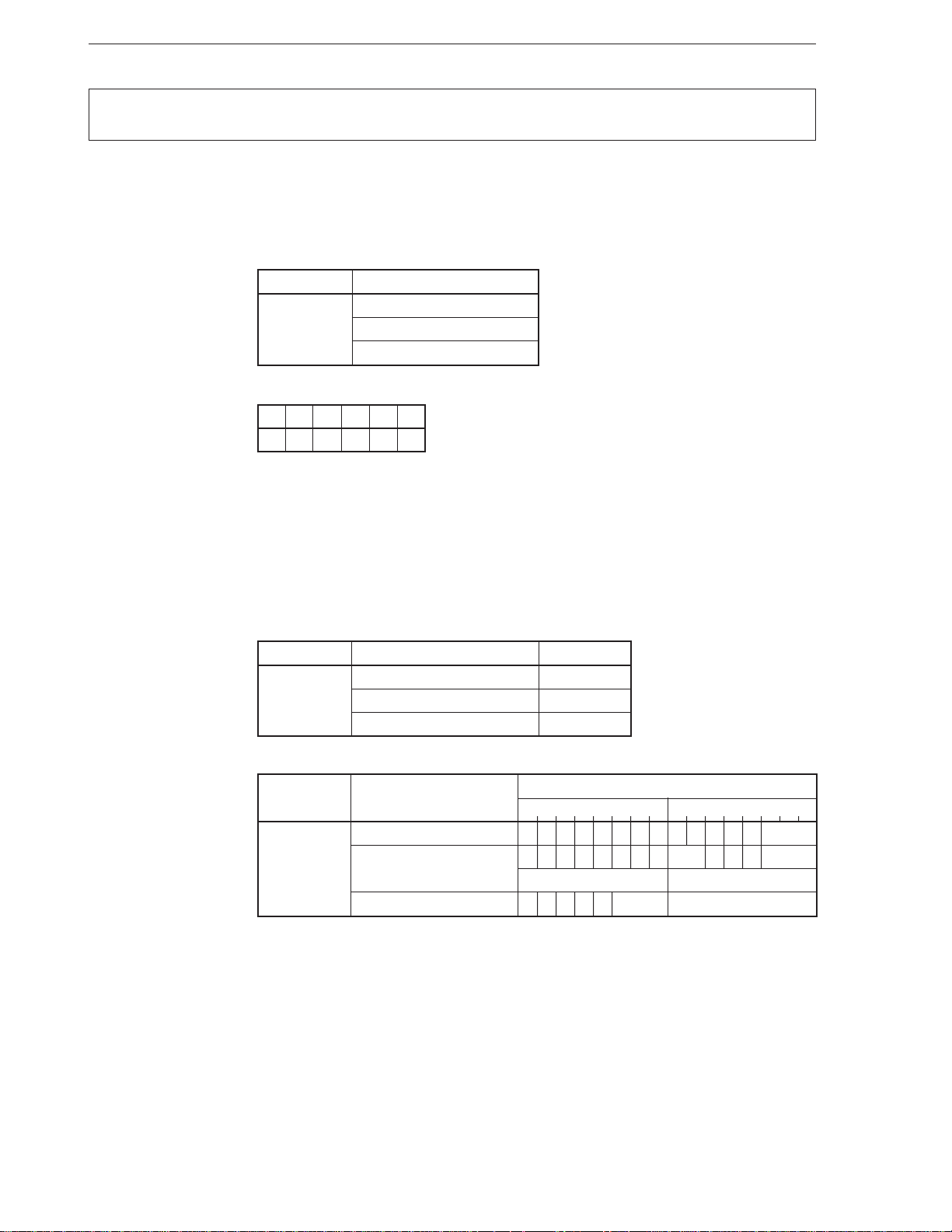
CHAPTER 2 INSTRUCTIONS
DEC
[Format] DEC dst
[Operation] dst ← dst – 1
[Operand]
[Flag]
[Description] Decrements the contents of the destination operand (dst) (–1).
[Example] • DEC BW
Mnemonic Operand
DEC reg8
mem
reg16
AC CY V P S Z
× ××××
• DEC BP
• DEC IX
• DEC IY
Decrement
Decrement
[Number of bytes]
[Word format]
Mnemonic Operand No. of bytes
DEC reg8 2
mem 2-4
reg16 1
Mnemonic Operand
7654321076543210
DEC reg8 1111111011001 reg
mem 1111111Wmod001 mem
(disp-low) (disp-high)
reg16 01001 reg —
Operation code
72
Page 84
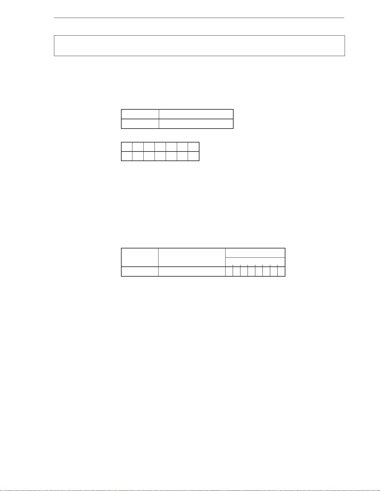
CHAPTER 2 INSTRUCTIONS
DI
Disable Interrupt
[Format] DI
[Operation] IE ← 0
Disable maskable interrupt
[Operand]
[Flag]
Mnemonic Operand
DI None
AC CY V P S Z IE
0
[Description] Resets the IE flag to 0 and disables the maskable interrupt. This instruction does not disable
the non-maskable interrupt request and software interrupt request.
[Example] DI
PUSH R
[Number of bytes] 1
[Word format]
Mnemonic Operand
DI None 11111010
Operation code
76543210
73
Page 85
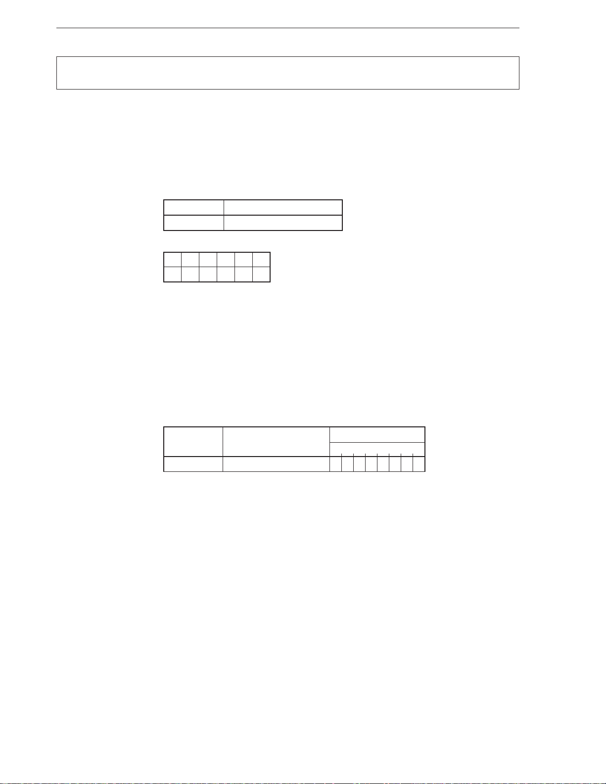
CHAPTER 2 INSTRUCTIONS
DISPOSE
[Format] DISPOSE
[Operation] SP ← BP
BP ← (SP + 1, SP)
SP ← SP + 2
[Operand]
[Flag]
[Description] This instruction releases one frame of the stack frame created by the PREPARE instruction.
Mnemonic Operand
DISPOSE None
AC CY V P S Z
A pointer value indicating one frame before is loaded to the BP, and a pointer value
indicating the lowest frame is loaded to the SP.
Deletes a stack frame
Dispose a Stack Frame
[Example] DISPOSE
[Number of bytes] 1
[Word format]
Mnemonic Operand
DISPOSE None 11001001
Operation code
76543210
74
Page 86
CHAPTER 2 INSTRUCTIONS
DIV
[Format] DIV dst
[Operand, operation]
Mnemonic Operand (dst) Operation
DIV reg8 temp ← AW
Signed division
Divide Signed
Where temp ÷ dst > 0 and temp ÷ dst ≤ 7FH or,
where temp ÷ dst < 0 and temp ÷ dst > 0 – 7FH – 1,
AH ← temp%dst
AL ← temp ÷ dst
Where temp ÷ dst > 0 and temp ÷ dst > 7FH or,
where temp ÷ dst < 0 and temp ÷ dst ≤ 0 – 7FH – 1,
quotient and remainder are undefined.
mem8 TA ← (001H, 000H)
TC ← (003H, 002H)
SP ← SP – 2, (SP + 1, SP) ← PSW
IE ← 0, BRK ← 0
SP ← SP – 2, (SP + 1, SP) ← PS
PS ← TC
SP ← SP – 2, (SP + 1, SP) ← PC
PC ← TA
reg16 temp ← DW, AW
Where temp ÷ dst > 0 and temp ÷ dst ≤ 7FFFH or,
where temp ÷ dst < 0 and temp ÷ dst > 0 – 7FFFH – 1,
DW ← temp%dst
AW ← temp ÷ dst
Where temp ÷ dst > 0 and temp ÷ dst > 7FFFH or,
where temp ÷ dst < 0 and temp ÷ dst ≤ 0 – 7FFFH – 1,
quotient and remainder are undefined.
mem16 TA ← (001H, 000H)
TC ← (003H, 002H)
SP ← SP – 2, (SP + 1, SP) ← PSW
IE ← 0, BRK ← 0
SP ← SP – 2, (SP + 1, SP) ← PS
PS ← TC
SP ← SP – 2, (SP + 1, SP) ← PC
PC ← TA
[Flag]
AC CY V P S Z
UUUUUU
75
Page 87
CHAPTER 2 INSTRUCTIONS
[Description] • Where src = reg8 or src = mem8
Divides the value of the AW register by the contents of the destination operand (dst)
with sign.
The quotient is stored to the AL register, and the remainder is stored to the AH register.
The maximum value of the positive quotient is +127 (7FH), and the minimum value is
–127 (81H). If the quotient is positive and is greater than the maximum value, or if the
quotient is negative and is less than the minimum value, vector 0 interrupt occurs
(especially where src = 00H), and the quotient and remainder are undefined. If the
quotient is not an integer, it is rounded to an integer, and the remainder has the same
sign as the dividend.
• Where src = reg16 or src = mem16
Divides the values of the AW and DW registers by the contents of the destination
operand (dst) with sign.
The quotient is stored to the AW register, and the remainder is stored to the DW register.
The maximum value of the positive quotient is +32767 (7FFFH), and the minimum value
is –32767 (8001H). If the quotient is positive and is greater than the maximum value,
or if the quotient is negative and is less than the minimum value, vector 0 interrupt occurs
(especially where src = 0000H), and the quotient and remainder are undefined. If the
quotient is not an integer, it is rounded to an integer, and the remainder has the same
sign as the dividend.
[Example] To divide 32-bit data DW:AW by contents of memory 0:50
MOV BW, 0
MOV DS0, BW
MOV IX, 50H
DIV DS0:WORD PTR [IX]
[Number of bytes]
Mnemonic Operand No. of bytes
DIV reg8 2
mem8 2-4
reg16 2
mem16 2-4
[Word format]
Mnemonic Operand
DIV reg8 1111011011111 reg
mem8 11110110mod111 mem
reg16 1111011111111 reg
mem16 11110111mod111 mem
7654321076543210
(disp-low) (disp-high)
(disp-low) (disp-high)
Operation code
76
Page 88
CHAPTER 2 INSTRUCTIONS
DIVU
[Format] DIVU dst
[Operand, operation]
Mnemonic Operand (dst) Operation
DIVU reg8 temp ← AW
Unsigned division
Divide Unsigned
Where temp ÷ dst ≥ FFH:
AH ← temp%dst
AL ← temp ÷ dst
Where temp ÷ dst > FFH:
TA ← (001H, 000H)
mem8 TC ← (003H, 002H)
SP ← SP – 2, (SP + 1, SP) ← PSW
IE ← 0, BRK ← 0
SP ← SP – 2, (SP + 1, SP) ← PS
RS ← TC
SP ← SP – 2, (SP + 1, SP) ← PC
PC ← TA
reg16 temp ← DW, AW
Where temp ÷ dst ≥ FFFFH:
DW ← temp%dst
AW ← temp ÷ dst
Where temp ÷ dst > FFFFH:
TA ← (001H, 000H)
mem16 TC ← (003H, 002H)
SP ← SP – 2, (SP + 1, SP) ← PSW
IE ← 0, BRK ← 0
SP ← SP – 2, (SP + 1, SP) ← PS
RS ← TC
SP ← SP – 2, (SP + 1, SP) ← PC
PC ← TA
[Flag]
AC CY V P S Z
UUUUUU
77
Page 89
CHAPTER 2 INSTRUCTIONS
[Description] • Where src = reg8 or src = mem8
Divides the value of the AW register by the contents of the destination operand (dst)
without sign. The quotient is stored to the AL register, and the remainder is stored to
the AH register.
If the quotient exceeds the capacity of the AL register (FFH), vector 0 interrupt occurs
(especially where src = 00H), and the quotient and remainder are undefined. If the
quotient is not an integer, it is rounded to an integer.
• Where src = reg16 or src = mem16
Divides the values of the AW and DW registers by the contents of the destination
operand (dst) without sign. The quotient is stored to the AW register, and the remainder
is stored to the DW register.
If the quotient exceeds the capacity of the AW register (FFFFH), vector 0 interrupt occurs
(especially where src = 0000H), and the quotient and remainder are undefined. If the
quotient is not an integer, it is rounded to an integer.
[Example] To divide 5 by 3
MOV AW, 5
MOV DL, 3
DIVU DL
; AH = 2 AL = 1
[Number of bytes]
[Word format]
Mnemonic Operand No. of bytes
DIVU reg8 2
mem8 2-4
reg16 2
mem16 2-4
Mnemonic Operand
7654321076543210
DIVU reg8 1111011011110 reg
mem8 11110110mod110 mem
(disp-low) (disp-high)
reg16 1111011111110 reg
mem16 11110111mod110 mem
(disp-low) (disp-high)
Operation code
78
Page 90
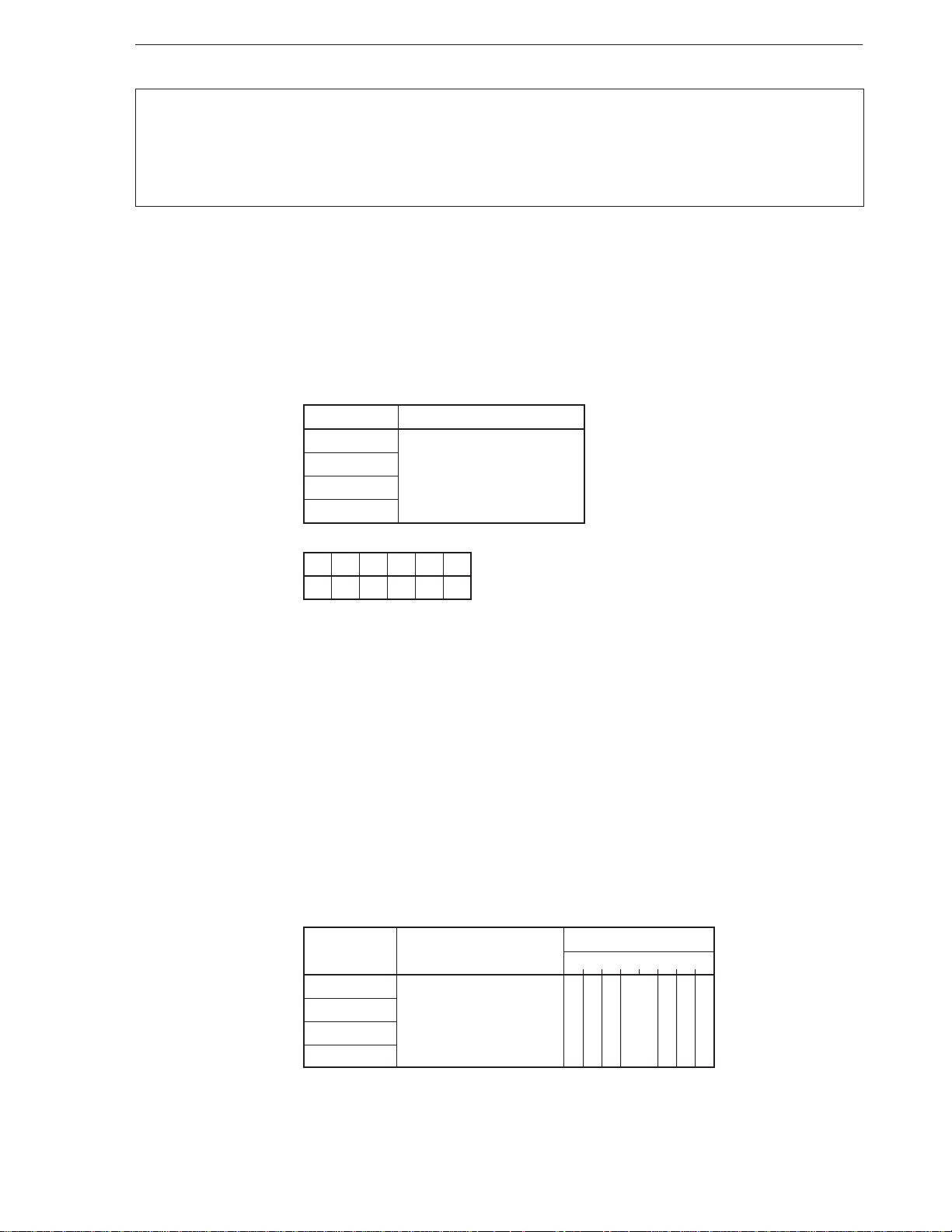
CHAPTER 2 INSTRUCTIONS
DS0:
DS1:
PS:
Segment override prefix
Data Segment 0
Data Segment 1
Program Segment
SS: Stack Segment
[Format] DS0:
DS1:
PS:
SS:
[Operation] Segment override prefix
[Operand]
Mnemonic Operand
DS0: None
DS1:
PS:
SS:
[Flag]
[Description] When a memory operand is accessed for which segment override is enabled, specifies a
[Example] MOV DW, DS1: [BW]; Default segment register is DS0
[Number of bytes] 1
[Word Format]
AC CY V P S Z
segment register that is described as an operand and used. Even if this instruction is not
directly described, segment override can be specified by the assembler if the ASSUME
(assembler directive) is used.
Caution The hardware interrupt (maskable interrupt and non-maskable interrupt)
request and single-step break cannot be accepted between this instruction
and the next instruction.
Mnemonic Operand
DS0: None 0 0 1 sreg 1 1 0
DS1:
PS:
SS:
Operation code
76543210
79
Page 91
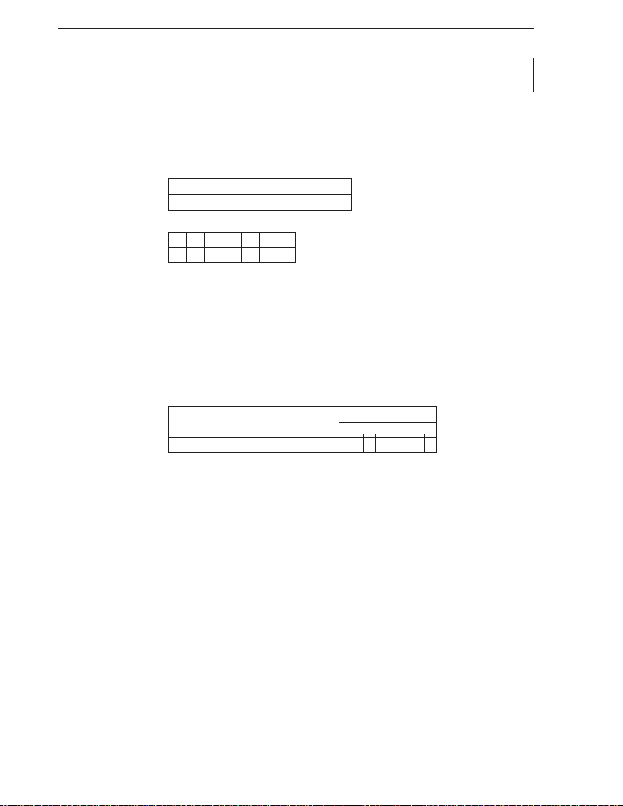
CHAPTER 2 INSTRUCTIONS
EI
Enable Interrupt
[Format] EI
[Operation] IE ← 1
Enables maskable interrupt
[Operand]
[Flag]
Mnemonic Operand
EI None
AC CY V P S Z IE
1
[Description] Sets the IE flag to 1 and enables the maskable interrupt. However, the interrupt is actually
enabled when the single instruction following the EI instruction is executed.
[Example] POP R
EI
[Number of bytes] 1
[Word format]
Mnemonic Operand
EI None 11111011
Operation code
76543210
80
Page 92
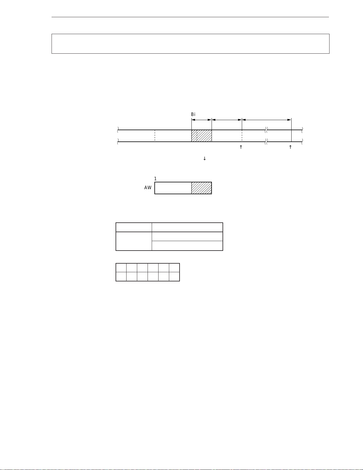
CHAPTER 2 INSTRUCTIONS
,
EXT
[Format] EXT dst, src
[Operation] AW ← 16-bit field
15 0
Extracts bit field
Extract Bit Field
Bit length Bit offset
↓↓
Byte boundary Segment base
↓
0AW
(IX)
Byte offset
Memory
(default DS0)
[Operand]
[Flag]
Mnemonic Operand (dst, src)
EXT reg8, reg8’
reg8, imm4
AC CY V P S Z
UUUUUU
[Description] Loads bit field data of the bit length specified by the source operand (src) from a memory
area determined by byte offset addressed by the IX register and the bit offset specified by
the 8-bit register described as the first operand to the AW register. At this time, 0 is loaded
to the high-order bits of the AW register.
After completion of the transfer, the IX register and the 8-bit register specified by the first
operand are automatically updated to indicate the next bit field, as follows:
reg8 ← reg8 + src + 1
if reg8 > 15 then
{
reg8 ← reg8 – 16
IX ← IX + 2
}
81
Page 93
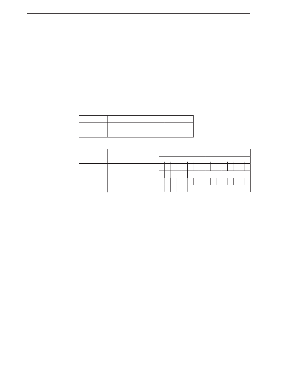
The value of the 8-bit register of the first operand that specifies a bit offset (15 bits max.)
must be 0 to 15. The value of the source operand (src) that specifies the bit length (16 bits
max.) must be 0 to 15. 0 indicates a length of 1 bit and 15 indicates a length of 16 bits.
The bit field data can straddle a byte boundary of memory.
The default segment register for the bit field of the source is the DS0 register, and segments
can be overridden. The data can be located in any segment that is specified by any segment
register.
Caution Clear the high-order 4 bits of reg8 or reg8’ to 0.
[Example] • EXT CL, DL
• EXT CL, 8
CHAPTER 2 INSTRUCTIONS
[Number of bytes]
[Word format]
Mnemonic Operand No. of bytes
EXT reg8, reg8’ 3
reg8, imm4 4
Mnemonic Operand
7654321076543210
EXT reg8, reg8’ 0000111100110011
1 1 reg’ reg –
reg8, imm4 0000111100111011
11000 reg imm4
Operation code
82
Page 94
CHAPTER 2 INSTRUCTIONS
FPO1
[Format] (1) FPO1 fp-op
(2) FPO1 fp-op, mem
[Operand, operation]
Format (1)
Mnemonic Operand Operation
FPO1 fp-op No operation
Format (2)
Mnemonic Operand Operation
FPO1 fp-op, mem Data bus ← (mem)
[Flag]
AC CY V P S Z
Controls floating-point coprocessor
Floating Point Operation 1
[Description] Format (1): This instruction is used to control an externally connected floating-point
coprocessor. When the CPU fetches this instruction, it executes nothing but
lets the coprocessor perform processing.
Format (2): This instruction is used to control an externally connected floating-point
coprocessor. When the CPU fetches this instruction, it lets the coprocessor
perform processing and, if necessary, executes only auxiliary processing
(such as effective address calculation, physical address generation, and
starting a memory read cycle). The CPU does not read the data on the data
bus in the memory read cycle started by CPU.
[Example] • FPO1 010101010B
• FPO1 0FFH
• FPO1 6, BYTE PTR [IX]
• FPO1 4, WORD_VAR
[Number of bytes]
Mnemonic Operand No. of bytes
FPO1 fp-op 2
fp-op, mem 2-4
83
Page 95
CHAPTER 2 INSTRUCTIONS
[Word format]
Mnemonic Operand
7654321076543210
FPO1 fp-op 11011XXX11YYYZZZ
fp-op, mem 11011XXXmodYYY mem
(disp-low) (disp-high)
Operation code
84
Page 96
CHAPTER 2 INSTRUCTIONS
FPO2
[Format] (1) FPO2 fp-op
(2) FPO2 fp-op, mem
[Operand, operation]
Format (1)
Mnemonic Operand Operation
FPO2 fp-op No operation
Format (2)
Mnemonic Operand Operation
FPO2 fp-op, mem Data bus ← (mem)
[Flag]
AC CY V P S Z
Controls floating-point coprocessor
Floating Point Operation 2
[Description] Format (1): This instruction is used to control an externally connected floating-point
coprocessor. When the CPU fetches this instruction, it executes nothing but
lets the coprocessor perform processing.
Format (2): This instruction is used to control an externally connected floating-point
coprocessor. When the CPU fetches this instruction, it lets the coprocessor
perform processing and, if necessary, executes only auxiliary processing
(such as effective address calculation, physical address generation, and
starting a memory read cycle). The CPU does not read the data on the data
bus in the memory read cycle started by CPU.
[Example] • FPO2 010101010B
• FPO2 0FFH
• FPO2 0101B, BYTE PTR [IY]
• FPO2 1010B, WORD_VAR
[Number of bytes]
Mnemonic Operand No. of bytes
FPO2 fp-op 2
fp-op, mem 2-4
85
Page 97
CHAPTER 2 INSTRUCTIONS
[Word format]
Mnemonic Operand
7654321076543210
FPO2 fp-op 0110011X11YYYZZZ
fp-op, mem 0110011XmodYYY mem
(disp-low) (disp-high)
Operation code
86
Page 98
CHAPTER 2 INSTRUCTIONS
HALT
[Format] HALT
[Operation] CPU Halt
[Operand]
[Flag]
[Description] Stops clock supply to the CPU and sets the standby mode. The standby mode is released
Mnemonic Operand
HALT None
AC CY V P S Z
by the following:
• Reset input
• Maskable interrupt request input
• Non-maskable interrupt request input
Halt
Halt
[Example] HALT
[Number of bytes] 1
[Word format]
Mnemonic Operand
HALT None 11110100
Operation code
76543210
87
Page 99
CHAPTER 2 INSTRUCTIONS
IN
Input
[Format] IN dst, src
[Operand, operation]
Data input from I/O device
Mnemonic Operand (dst, src) Operation
IN acc, imm8 [When W = 0] AL ← (imm8)
[When W = 1] AH ← (imm8 + 1), AL ← (imm8)
acc, DW [When W = 0] AL ← (DW)
[When W = 1] AH ← (DW + 1), AL ← (DW)
[Flag]
AC CY V P S Z
[Description] Transfers the register contents of the I/O device specified by the source operand (src) to
the accumulator (AL or AW register) specified by the destination operand (dst).
[Example] To transfer contents of port address 0DAH to AL register
MOV DW, 0DAH
IN AL, DW
[Number of bytes]
Mnemonic Operand No. of bytes
IN acc, imm8 2
acc, DW 1
[Word format]
Mnemonic Operand
IN acc, imm8 1110010W imm8
acc, DW 1110110W —
7654321076543210
Operation code
88
Page 100
CHAPTER 2 INSTRUCTIONS
INC
[Format] INC dst
[Operation] dst ← dst + 1
[Operand]
[Flag]
[Description] Increments the contents of the destination operand (dst) (+1).
[Example] • INC DW
Mnemonic Operand (dst)
INC reg8
mem
reg16
AC CY V P S Z
× ××××
• INC BP
• INC SP
Increment
Increment
[Number of bytes]
[Word format]
Mnemonic Operand No. of bytes
INC reg8 2
mem 2-4
reg16 1
Mnemonic Operand
7654321076543210
INC reg8 1111111011000 reg
mem 1111111Wmod000 mem
(disp-low) (disp-high)
reg16 01000 reg —
Operation code
89
 Loading...