

Page 1

PROPERTY MANAGEMENT SYSTEM
COMMUNICATION INTERFACE SPECIFICATION
NEC America, Inc.
NDA-30115-001
Revision 1.0
June, 1998
Stock # 241727
Page 2

LIABILITY DISCLAIMER
NEC America reserves the right to change the specifications, functions,
or features in this document at any time without notice. NEC America
has prepared this document for use by its employees and customers. The
information contained herein is the property of NEC America and shall
not be reproduced without prior written approval from NEC America.
Copyright 1999
NEC America, Inc.
Page 3

Property Management System Communication Interface CONTENTS
TABLE OF CONTENTS
Page
Chapter 1 - Overview. . . . . . . . . . . . . . . . . . . . . . . . . . . . . . . . . . . . . . . . . . . . . . . . . . . . . 1
Chapter 2 - Architecture . . . . . . . . . . . . . . . . . . . . . . . . . . . . . . . . . . . . . . . . . . . . . . . . . . 3
Asynchronous Transmission. . . . . . . . . . . . . . . . . . . . . . . . . . . . . . . . . . . . . . . . . . . . . . . . . . . . . . 4
Line Control Characteristics. . . . . . . . . . . . . . . . . . . . . . . . . . . . . . . . . . . . . . . . . . . . . . . . . . . . . 4
Transmission Protocol . . . . . . . . . . . . . . . . . . . . . . . . . . . . . . . . . . . . . . . . . . . . . . . . . . . . . . . . . 5
Transmission Sequence . . . . . . . . . . . . . . . . . . . . . . . . . . . . . . . . . . . . . . . . . . . . . . . . . . . . . . . 7
From the NEAX to the PMS . . . . . . . . . . . . . . . . . . . . . . . . . . . . . . . . . . . . . . . . . . . . . . . . . . . 8
From the PMS to the NEAX . . . . . . . . . . . . . . . . . . . . . . . . . . . . . . . . . . . . . . . . . . . . . . . . . . . 9
Timers . . . . . . . . . . . . . . . . . . . . . . . . . . . . . . . . . . . . . . . . . . . . . . . . . . . . . . . . . . . . . . . . . . . . 10
Sender Timer . . . . . . . . . . . . . . . . . . . . . . . . . . . . . . . . . . . . . . . . . . . . . . . . . . . . . . . . . . . . . 10
Receiver Timer . . . . . . . . . . . . . . . . . . . . . . . . . . . . . . . . . . . . . . . . . . . . . . . . . . . . . . . . . . . . 10
Cabling Considerations . . . . . . . . . . . . . . . . . . . . . . . . . . . . . . . . . . . . . . . . . . . . . . . . . . . . . . . 10
Bisynchronous (BSC) Transmiss ion. . . . . . . . . . . . . . . . . . . . . . . . . . . . . . . . . . . . . . . . . . . . . . . 10
Line Control Characteristics. . . . . . . . . . . . . . . . . . . . . . . . . . . . . . . . . . . . . . . . . . . . . . . . . . . . 10
Transmission Protocol . . . . . . . . . . . . . . . . . . . . . . . . . . . . . . . . . . . . . . . . . . . . . . . . . . . . . . . . 13
Transmission Sequence . . . . . . . . . . . . . . . . . . . . . . . . . . . . . . . . . . . . . . . . . . . . . . . . . . . . . . 15
Timers and Counters . . . . . . . . . . . . . . . . . . . . . . . . . . . . . . . . . . . . . . . . . . . . . . . . . . . . . . . . . 17
Retransmission Counts. . . . . . . . . . . . . . . . . . . . . . . . . . . . . . . . . . . . . . . . . . . . . . . . . . . . . . 17
Timer Values. . . . . . . . . . . . . . . . . . . . . . . . . . . . . . . . . . . . . . . . . . . . . . . . . . . . . . . . . . . . . . 17
Cabling Considerations . . . . . . . . . . . . . . . . . . . . . . . . . . . . . . . . . . . . . . . . . . . . . . . . . . . . . . . 18
Chapter 3 - Message Descriptions. . . . . . . . . . . . . . . . . . . . . . . . . . . . . . . . . . . . . . . . . 19
Data Link Maintenance. . . . . . . . . . . . . . . . . . . . . . . . . . . . . . . . . . . . . . . . . . . . . . . . . . . . . . . . . 19
Data Link Failure . . . . . . . . . . . . . . . . . . . . . . . . . . . . . . . . . . . . . . . . . . . . . . . . . . . . . . . . . . . . 20
Release for Maintenance. . . . . . . . . . . . . . . . . . . . . . . . . . . . . . . . . . . . . . . . . . . . . . . . . . . . . . 21
NEAX Operations During Loss of Communication . . . . . . . . . . . . . . . . . . . . . . . . . . . . . . . . . . 21
Recovery from Loss of Communication . . . . . . . . . . . . . . . . . . . . . . . . . . . . . . . . . . . . . . . . . . . 21
Maid Status. . . . . . . . . . . . . . . . . . . . . . . . . . . . . . . . . . . . . . . . . . . . . . . . . . . . . . . . . . . . . . . . . . 22
Message Waiting Lamp Control . . . . . . . . . . . . . . . . . . . . . . . . . . . . . . . . . . . . . . . . . . . . . . . . . . 23
Restriction Control . . . . . . . . . . . . . . . . . . . . . . . . . . . . . . . . . . . . . . . . . . . . . . . . . . . . . . . . . . . . 23
Check In/Check Out (Model 60) . . . . . . . . . . . . . . . . . . . . . . . . . . . . . . . . . . . . . . . . . . . . . . . . . . 23
Check In/Check Out (Model 90) . . . . . . . . . . . . . . . . . . . . . . . . . . . . . . . . . . . . . . . . . . . . . . . . . . 24
Wake Up/Group Announcement. . . . . . . . . . . . . . . . . . . . . . . . . . . . . . . . . . . . . . . . . . . . . . . . . . 25
Room Move/Swap/Copy (Model 60). . . . . . . . . . . . . . . . . . . . . . . . . . . . . . . . . . . . . . . . . . . . . . . 25
Room Data Change . . . . . . . . . . . . . . . . . . . . . . . . . . . . . . . . . . . . . . . . . . . . . . . . . . . . . . . . . . . 26
Extension Report . . . . . . . . . . . . . . . . . . . . . . . . . . . . . . . . . . . . . . . . . . . . . . . . . . . . . . . . . . . . . 26
Room Recovery (Model 60) . . . . . . . . . . . . . . . . . . . . . . . . . . . . . . . . . . . . . . . . . . . . . . . . . . . . . 27
Room Recovery (Model 90) . . . . . . . . . . . . . . . . . . . . . . . . . . . . . . . . . . . . . . . . . . . . . . . . . . . . . 28
Direct Data Entry (Model 90) . . . . . . . . . . . . . . . . . . . . . . . . . . . . . . . . . . . . . . . . . . . . . . . . . . . . 28
Extension Connection. . . . . . . . . . . . . . . . . . . . . . . . . . . . . . . . . . . . . . . . . . . . . . . . . . . . . . . . . . 29
Chapter 4 - Message Formats. . . . . . . . . . . . . . . . . . . . . . . . . . . . . . . . . . . . . . . . . . . . . 31
Data Link Maintenance. . . . . . . . . . . . . . . . . . . . . . . . . . . . . . . . . . . . . . . . . . . . . . . . . . . . . . . . . 32
Maid Status. . . . . . . . . . . . . . . . . . . . . . . . . . . . . . . . . . . . . . . . . . . . . . . . . . . . . . . . . . . . . . . . . . 33
Cleaning. . . . . . . . . . . . . . . . . . . . . . . . . . . . . . . . . . . . . . . . . . . . . . . . . . . . . . . . . . . . . . . . . . . 34
Guest Room. . . . . . . . . . . . . . . . . . . . . . . . . . . . . . . . . . . . . . . . . . . . . . . . . . . . . . . . . . . . . . . . 35
Room Answer . . . . . . . . . . . . . . . . . . . . . . . . . . . . . . . . . . . . . . . . . . . . . . . . . . . . . . . . . . . . . . 36
NDA-30115Revision 1.0 Page i
Page 4

CONTENTS Property Management System Communication Interface
Page
Administration . . . . . . . . . . . . . . . . . . . . . . . . . . . . . . . . . . . . . . . . . . . . . . . . . . . . . . . . . . . . . . 37
Message Waiting Lamp Control . . . . . . . . . . . . . . . . . . . . . . . . . . . . . . . . . . . . . . . . . . . . . . . . . . 38
MWL Control . . . . . . . . . . . . . . . . . . . . . . . . . . . . . . . . . . . . . . . . . . . . . . . . . . . . . . . . . . . . . . . 38
MWL Status . . . . . . . . . . . . . . . . . . . . . . . . . . . . . . . . . . . . . . . . . . . . . . . . . . . . . . . . . . . . . . . . 39
Restriction Control . . . . . . . . . . . . . . . . . . . . . . . . . . . . . . . . . . . . . . . . . . . . . . . . . . . . . . . . . . . . 40
Check In/Check Out (Model 60) . . . . . . . . . . . . . . . . . . . . . . . . . . . . . . . . . . . . . . . . . . . . . . . . . . 41
Check In 1 . . . . . . . . . . . . . . . . . . . . . . . . . . . . . . . . . . . . . . . . . . . . . . . . . . . . . . . . . . . . . . . . . 41
Check Out . . . . . . . . . . . . . . . . . . . . . . . . . . . . . . . . . . . . . . . . . . . . . . . . . . . . . . . . . . . . . . . . . 42
Check Out Message Report. . . . . . . . . . . . . . . . . . . . . . . . . . . . . . . . . . . . . . . . . . . . . . . . . . . . 42
Check In 2 . . . . . . . . . . . . . . . . . . . . . . . . . . . . . . . . . . . . . . . . . . . . . . . . . . . . . . . . . . . . . . . . . 43
Check In 3 . . . . . . . . . . . . . . . . . . . . . . . . . . . . . . . . . . . . . . . . . . . . . . . . . . . . . . . . . . . . . . . . . 44
Check Out Outgoing Call Report . . . . . . . . . . . . . . . . . . . . . . . . . . . . . . . . . . . . . . . . . . . . . . . . 45
Check Out Message Waiting Report . . . . . . . . . . . . . . . . . . . . . . . . . . . . . . . . . . . . . . . . . . . . . 45
Check In/Check Out (Model 90) . . . . . . . . . . . . . . . . . . . . . . . . . . . . . . . . . . . . . . . . . . . . . . . . . . 46
Check In. . . . . . . . . . . . . . . . . . . . . . . . . . . . . . . . . . . . . . . . . . . . . . . . . . . . . . . . . . . . . . . . . . . 46
Check Out . . . . . . . . . . . . . . . . . . . . . . . . . . . . . . . . . . . . . . . . . . . . . . . . . . . . . . . . . . . . . . . . . 48
Check In Cancellation . . . . . . . . . . . . . . . . . . . . . . . . . . . . . . . . . . . . . . . . . . . . . . . . . . . . . . . . 49
Check Out Cancellation . . . . . . . . . . . . . . . . . . . . . . . . . . . . . . . . . . . . . . . . . . . . . . . . . . . . . . . 49
Room Change . . . . . . . . . . . . . . . . . . . . . . . . . . . . . . . . . . . . . . . . . . . . . . . . . . . . . . . . . . . . . . 50
Provisional Check In . . . . . . . . . . . . . . . . . . . . . . . . . . . . . . . . . . . . . . . . . . . . . . . . . . . . . . . . . 51
Provisional Check Out. . . . . . . . . . . . . . . . . . . . . . . . . . . . . . . . . . . . . . . . . . . . . . . . . . . . . . . . 52
Check Out Message Waiting Report . . . . . . . . . . . . . . . . . . . . . . . . . . . . . . . . . . . . . . . . . . . . . 52
Wake Up/Group Announcement. . . . . . . . . . . . . . . . . . . . . . . . . . . . . . . . . . . . . . . . . . . . . . . . . . 53
Wake Up Setting (NEAX). . . . . . . . . . . . . . . . . . . . . . . . . . . . . . . . . . . . . . . . . . . . . . . . . . . . . . 53
Wake Up Cancellation (NEAX) . . . . . . . . . . . . . . . . . . . . . . . . . . . . . . . . . . . . . . . . . . . . . . . . . 54
Wake Up Execution Result . . . . . . . . . . . . . . . . . . . . . . . . . . . . . . . . . . . . . . . . . . . . . . . . . . . . 55
Wake Up Setting (PMS). . . . . . . . . . . . . . . . . . . . . . . . . . . . . . . . . . . . . . . . . . . . . . . . . . . . . . . 56
Wake Up Cancellation (PMS) . . . . . . . . . . . . . . . . . . . . . . . . . . . . . . . . . . . . . . . . . . . . . . . . . . 57
Group Announcement Setting (NEAX) . . . . . . . . . . . . . . . . . . . . . . . . . . . . . . . . . . . . . . . . . . . 58
Group Announcement Cancellation (NEAX) . . . . . . . . . . . . . . . . . . . . . . . . . . . . . . . . . . . . . . . 59
Group Announcement Execution Result . . . . . . . . . . . . . . . . . . . . . . . . . . . . . . . . . . . . . . . . . . 60
Group Announcement Setting (PMS) . . . . . . . . . . . . . . . . . . . . . . . . . . . . . . . . . . . . . . . . . . . . 61
Group Announcement Cancellation (PMS) . . . . . . . . . . . . . . . . . . . . . . . . . . . . . . . . . . . . . . . . 62
Room Move/Swap/Copy (Model 60). . . . . . . . . . . . . . . . . . . . . . . . . . . . . . . . . . . . . . . . . . . . . . . 63
Room Data Change . . . . . . . . . . . . . . . . . . . . . . . . . . . . . . . . . . . . . . . . . . . . . . . . . . . . . . . . . . . 64
Room Data Change 60 . . . . . . . . . . . . . . . . . . . . . . . . . . . . . . . . . . . . . . . . . . . . . . . . . . . . . . . 64
Group Formation . . . . . . . . . . . . . . . . . . . . . . . . . . . . . . . . . . . . . . . . . . . . . . . . . . . . . . . . . . . . 65
Group Cancellation . . . . . . . . . . . . . . . . . . . . . . . . . . . . . . . . . . . . . . . . . . . . . . . . . . . . . . . . . . 66
Reservation Setting . . . . . . . . . . . . . . . . . . . . . . . . . . . . . . . . . . . . . . . . . . . . . . . . . . . . . . . . . . 66
Reservation Cancellation. . . . . . . . . . . . . . . . . . . . . . . . . . . . . . . . . . . . . . . . . . . . . . . . . . . . . . 66
Guest Name Change. . . . . . . . . . . . . . . . . . . . . . . . . . . . . . . . . . . . . . . . . . . . . . . . . . . . . . . . . 67
Room Data Change 90 . . . . . . . . . . . . . . . . . . . . . . . . . . . . . . . . . . . . . . . . . . . . . . . . . . . . . . . 67
Room Status Change. . . . . . . . . . . . . . . . . . . . . . . . . . . . . . . . . . . . . . . . . . . . . . . . . . . . . . . . . 69
Room Key Status Change . . . . . . . . . . . . . . . . . . . . . . . . . . . . . . . . . . . . . . . . . . . . . . . . . . . . . 70
Extension Report . . . . . . . . . . . . . . . . . . . . . . . . . . . . . . . . . . . . . . . . . . . . . . . . . . . . . . . . . . . . . 70
Extension Delete Report . . . . . . . . . . . . . . . . . . . . . . . . . . . . . . . . . . . . . . . . . . . . . . . . . . . . . . 70
Extension Assignment Report . . . . . . . . . . . . . . . . . . . . . . . . . . . . . . . . . . . . . . . . . . . . . . . . . . 71
Room Recovery (Model 60) . . . . . . . . . . . . . . . . . . . . . . . . . . . . . . . . . . . . . . . . . . . . . . . . . . . . . 72
Room Image Set 1. . . . . . . . . . . . . . . . . . . . . . . . . . . . . . . . . . . . . . . . . . . . . . . . . . . . . . . . . . . 73
Room Image Set 2. . . . . . . . . . . . . . . . . . . . . . . . . . . . . . . . . . . . . . . . . . . . . . . . . . . . . . . . . . . 74
Room Image Set 3. . . . . . . . . . . . . . . . . . . . . . . . . . . . . . . . . . . . . . . . . . . . . . . . . . . . . . . . . . . 76
Page ii NDA-30115 Revision 1.0
Page 5

Property Management System Communication Interface CONTENTS
Page
Room Recovery (Model 90) . . . . . . . . . . . . . . . . . . . . . . . . . . . . . . . . . . . . . . . . . . . . . . . . . . . . . 78
Room Data Report. . . . . . . . . . . . . . . . . . . . . . . . . . . . . . . . . . . . . . . . . . . . . . . . . . . . . . . . . . . 78
Guest Room Secretary Telephone . . . . . . . . . . . . . . . . . . . . . . . . . . . . . . . . . . . . . . . . . . . . . . 80
Connecting Room . . . . . . . . . . . . . . . . . . . . . . . . . . . . . . . . . . . . . . . . . . . . . . . . . . . . . . . . . . . 80
Message Status Report . . . . . . . . . . . . . . . . . . . . . . . . . . . . . . . . . . . . . . . . . . . . . . . . . . . . . . . 81
Wake Up . . . . . . . . . . . . . . . . . . . . . . . . . . . . . . . . . . . . . . . . . . . . . . . . . . . . . . . . . . . . . . . . . . 82
Direct Data Entry (Model 90) . . . . . . . . . . . . . . . . . . . . . . . . . . . . . . . . . . . . . . . . . . . . . . . . . . . . 82
Direct Data Entry . . . . . . . . . . . . . . . . . . . . . . . . . . . . . . . . . . . . . . . . . . . . . . . . . . . . . . . . . . . . 83
Direct Data Entry Answer. . . . . . . . . . . . . . . . . . . . . . . . . . . . . . . . . . . . . . . . . . . . . . . . . . . . . . 83
Extension Connection. . . . . . . . . . . . . . . . . . . . . . . . . . . . . . . . . . . . . . . . . . . . . . . . . . . . . . . . . . 84
Guest Room Secretary Telephone . . . . . . . . . . . . . . . . . . . . . . . . . . . . . . . . . . . . . . . . . . . . . . 84
Connecting Room Set . . . . . . . . . . . . . . . . . . . . . . . . . . . . . . . . . . . . . . . . . . . . . . . . . . . . . . . . 85
Connecting Room Cancel . . . . . . . . . . . . . . . . . . . . . . . . . . . . . . . . . . . . . . . . . . . . . . . . . . . . . 85
Chapter 5 - References . . . . . . . . . . . . . . . . . . . . . . . . . . . . . . . . . . . . . . . . . . . . . . . . . . 87
Chapter 6 - Glossary . . . . . . . . . . . . . . . . . . . . . . . . . . . . . . . . . . . . . . . . . . . . . . . . . . . . 89
Appendix A - Room Status . . . . . . . . . . . . . . . . . . . . . . . . . . . . . . . . . . . . . . . . . . . . . . . A1
Updating Room Status Information in the NEAX . . . . . . . . . . . . . . . . . . . . . . . . . . . . . . . . . . . . . A2
Clearing Room Data . . . . . . . . . . . . . . . . . . . . . . . . . . . . . . . . . . . . . . . . . . . . . . . . . . . . . . . . . . . A2
Dial Steps for Maid Status . . . . . . . . . . . . . . . . . . . . . . . . . . . . . . . . . . . . . . . . . . . . . . . . . . . . . . A2
Room Status and Cleaning Status . . . . . . . . . . . . . . . . . . . . . . . . . . . . . . . . . . . . . . . . . . . . . . . . A3
Status of Check Out . . . . . . . . . . . . . . . . . . . . . . . . . . . . . . . . . . . . . . . . . . . . . . . . . . . . . . . . . . . A3
Room Data Setting and Clearing in the NEAX . . . . . . . . . . . . . . . . . . . . . . . . . . . . . . . . . . . . . . . A3
Appendix B - PMS Line Failure Printouts . . . . . . . . . . . . . . . . . . . . . . . . . . . . . . . . . . . B1
Normal Text . . . . . . . . . . . . . . . . . . . . . . . . . . . . . . . . . . . . . . . . . . . . . . . . . . . . . . . . . . . . . . . . . B1
Abnormal Events. . . . . . . . . . . . . . . . . . . . . . . . . . . . . . . . . . . . . . . . . . . . . . . . . . . . . . . . . . . . . . B2
Abnormal Port. . . . . . . . . . . . . . . . . . . . . . . . . . . . . . . . . . . . . . . . . . . . . . . . . . . . . . . . . . . . . . . . B2
Transmission Failure. . . . . . . . . . . . . . . . . . . . . . . . . . . . . . . . . . . . . . . . . . . . . . . . . . . . . . . . . . . B5
Appendix C - Feature Codes. . . . . . . . . . . . . . . . . . . . . . . . . . . . . . . . . . . . . . . . . . . . . . C1
Appendix D - Function Codes. . . . . . . . . . . . . . . . . . . . . . . . . . . . . . . . . . . . . . . . . . . . . D1
NDA-30115Revision 1.0 Page iii
Page 6

CONTENTS Property Management System Communication Interface
Page
Page iv NDA-30115 Revision 1.0
Page 7

Property Management System Communication Interface FIGURES
LIST OF FIGURES
Figure Title Page
2-1 Start Sequence . . . . . . . . . . . . . . . . . . . . . . . . . . . . . . . . . . . . . . . . . . . . . . . . . . . . . . . 5
2-2 NEAX to PMS Protocol . . . . . . . . . . . . . . . . . . . . . . . . . . . . . . . . . . . . . . . . . . . . . . . . . 8
2-3 PMS to NEAX protocol . . . . . . . . . . . . . . . . . . . . . . . . . . . . . . . . . . . . . . . . . . . . . . . . . 9
2-4 Direct Connection Pin Assignments . . . . . . . . . . . . . . . . . . . . . . . . . . . . . . . . . . . . . . 10
2-5 Base Me s sage Format . . . . . . . . . . . . . . . . . . . . . . . . . . . . . . . . . . . . . . . . . . . . . . . . 13
2-6 Messag e D a ta Fo r m a t. . . . . . . . . . . . . . . . . . . . . . . . . . . . . . . . . . . . . . . . . . . . . . . . . 13
2-7 Direct Connection Pin Assignments . . . . . . . . . . . . . . . . . . . . . . . . . . . . . . . . . . . . . . 18
4-1 Base Me s sage Format . . . . . . . . . . . . . . . . . . . . . . . . . . . . . . . . . . . . . . . . . . . . . . . . 31
4-2 Data Link Maintenance Message Format . . . . . . . . . . . . . . . . . . . . . . . . . . . . . . . . . . 33
4-3 Cleaning (General) . . . . . . . . . . . . . . . . . . . . . . . . . . . . . . . . . . . . . . . . . . . . . . . . . . . 34
4-4 Guest Room (General) . . . . . . . . . . . . . . . . . . . . . . . . . . . . . . . . . . . . . . . . . . . . . . . . 35
4-5 Room Answer (General) . . . . . . . . . . . . . . . . . . . . . . . . . . . . . . . . . . . . . . . . . . . . . . . 36
4-6 Administration (General) . . . . . . . . . . . . . . . . . . . . . . . . . . . . . . . . . . . . . . . . . . . . . . . 37
4-7 MWL Control (General). . . . . . . . . . . . . . . . . . . . . . . . . . . . . . . . . . . . . . . . . . . . . . . . 38
4-8 MWL Status. . . . . . . . . . . . . . . . . . . . . . . . . . . . . . . . . . . . . . . . . . . . . . . . . . . . . . . . . 39
4-9 Restriction Control. . . . . . . . . . . . . . . . . . . . . . . . . . . . . . . . . . . . . . . . . . . . . . . . . . . . 40
4-10 Check In 1 . . . . . . . . . . . . . . . . . . . . . . . . . . . . . . . . . . . . . . . . . . . . . . . . . . . . . . . . . . 41
4-11 Check Out . . . . . . . . . . . . . . . . . . . . . . . . . . . . . . . . . . . . . . . . . . . . . . . . . . . . . . . . . . 42
4-12 Check Out Message Waiting Lamp Report. . . . . . . . . . . . . . . . . . . . . . . . . . . . . . . . . 42
4-13 Check In 2 . . . . . . . . . . . . . . . . . . . . . . . . . . . . . . . . . . . . . . . . . . . . . . . . . . . . . . . . . . 43
4-14 Check In 3 . . . . . . . . . . . . . . . . . . . . . . . . . . . . . . . . . . . . . . . . . . . . . . . . . . . . . . . . . . 44
4-15 Check Out Outgoing Call Report. . . . . . . . . . . . . . . . . . . . . . . . . . . . . . . . . . . . . . . . . 45
4-16 Check Out . . . . . . . . . . . . . . . . . . . . . . . . . . . . . . . . . . . . . . . . . . . . . . . . . . . . . . . . . . 45
4-17 Check In . . . . . . . . . . . . . . . . . . . . . . . . . . . . . . . . . . . . . . . . . . . . . . . . . . . . . . . . . . . 46
4-18 Check Out . . . . . . . . . . . . . . . . . . . . . . . . . . . . . . . . . . . . . . . . . . . . . . . . . . . . . . . . . . 48
4-19 Check In Cance l l a tio n . . . . . . . . . . . . . . . . . . . . . . . . . . . . . . . . . . . . . . . . . . . . . . . . . 49
4-20 Check Out Can ce l la tion. . . . . . . . . . . . . . . . . . . . . . . . . . . . . . . . . . . . . . . . . . . . . . . . 49
4-21 Room Change. . . . . . . . . . . . . . . . . . . . . . . . . . . . . . . . . . . . . . . . . . . . . . . . . . . . . . . 50
4-22 Provisional Check In . . . . . . . . . . . . . . . . . . . . . . . . . . . . . . . . . . . . . . . . . . . . . . . . . . 51
4-23 Provisi onal Check out . . . . . . . . . . . . . . . . . . . . . . . . . . . . . . . . . . . . . . . . . . . . . . . . . 52
4-24 Check Out Message Waiting Report. . . . . . . . . . . . . . . . . . . . . . . . . . . . . . . . . . . . . . 52
4-25 Wake Up Setting (NEAX) . . . . . . . . . . . . . . . . . . . . . . . . . . . . . . . . . . . . . . . . . . . . . . 53
4-26 Wake Up Cancellation (NEAX) . . . . . . . . . . . . . . . . . . . . . . . . . . . . . . . . . . . . . . . . . . 54
4-27 Wake Up Execution Result . . . . . . . . . . . . . . . . . . . . . . . . . . . . . . . . . . . . . . . . . . . . . 55
4-28 Wake Up Setting (PMS) . . . . . . . . . . . . . . . . . . . . . . . . . . . . . . . . . . . . . . . . . . . . . . . 56
4-29 Wake Up Cancellation (PMS) . . . . . . . . . . . . . . . . . . . . . . . . . . . . . . . . . . . . . . . . . . . 57
4-30 Group Announcement Setting (NEAX) . . . . . . . . . . . . . . . . . . . . . . . . . . . . . . . . . . . . 58
4-31 Group Announcement Cancellation (NEAX). . . . . . . . . . . . . . . . . . . . . . . . . . . . . . . . 59
4-32 Group Announcement Execution Result . . . . . . . . . . . . . . . . . . . . . . . . . . . . . . . . . . . 60
4-33 Group Announ c e m e n t S e tt in g (P M S ) . . . . . . . . . . . . . . . . . . . . . . . . . . . . . . . . . . . . . 61
4-34 Group Announcement Cancellation (PMS). . . . . . . . . . . . . . . . . . . . . . . . . . . . . . . . . 62
4-35 Room Move/Swap/Copy . . . . . . . . . . . . . . . . . . . . . . . . . . . . . . . . . . . . . . . . . . . . . . . 63
4-36 Room Data Change 60 . . . . . . . . . . . . . . . . . . . . . . . . . . . . . . . . . . . . . . . . . . . . . . . . 64
4-37 Group Formation. . . . . . . . . . . . . . . . . . . . . . . . . . . . . . . . . . . . . . . . . . . . . . . . . . . . . 65
4-38 Group Cancellation . . . . . . . . . . . . . . . . . . . . . . . . . . . . . . . . . . . . . . . . . . . . . . . . . . . 66
4-39 Reservation Setting. . . . . . . . . . . . . . . . . . . . . . . . . . . . . . . . . . . . . . . . . . . . . . . . . . . 66
NDA-30115 Revision 1.0 Page v
Page 8

FIGURES Property Management System Communication Interface
Figure Title Page
4-40 Reservation Cancellation . . . . . . . . . . . . . . . . . . . . . . . . . . . . . . . . . . . . . . . . . . . . . . 66
4-41 Guest Name Change . . . . . . . . . . . . . . . . . . . . . . . . . . . . . . . . . . . . . . . . . . . . . . . . . 67
4-42 Room Data Change 90. . . . . . . . . . . . . . . . . . . . . . . . . . . . . . . . . . . . . . . . . . . . . . . . 67
4-43 Room Status Change . . . . . . . . . . . . . . . . . . . . . . . . . . . . . . . . . . . . . . . . . . . . . . . . . 69
4-44 Room Key Status Change. . . . . . . . . . . . . . . . . . . . . . . . . . . . . . . . . . . . . . . . . . . . . . 70
4-45 Extension Delet e Report. . . . . . . . . . . . . . . . . . . . . . . . . . . . . . . . . . . . . . . . . . . . . . . 70
4-46 Extension Assi gnment Report. . . . . . . . . . . . . . . . . . . . . . . . . . . . . . . . . . . . . . . . . . . 71
4-47 Room Image Set 1 . . . . . . . . . . . . . . . . . . . . . . . . . . . . . . . . . . . . . . . . . . . . . . . . . . . 73
4-48 Room Image Set 2 . . . . . . . . . . . . . . . . . . . . . . . . . . . . . . . . . . . . . . . . . . . . . . . . . . . 74
4-49 Room Image Set 3 . . . . . . . . . . . . . . . . . . . . . . . . . . . . . . . . . . . . . . . . . . . . . . . . . . . 76
4-50 Room Data Report . . . . . . . . . . . . . . . . . . . . . . . . . . . . . . . . . . . . . . . . . . . . . . . . . . . 78
4-51 Guest Room Secretary Telephone . . . . . . . . . . . . . . . . . . . . . . . . . . . . . . . . . . . . . . . 80
4-52 Connecting Room. . . . . . . . . . . . . . . . . . . . . . . . . . . . . . . . . . . . . . . . . . . . . . . . . . . . 80
4-53 Message Status Report. . . . . . . . . . . . . . . . . . . . . . . . . . . . . . . . . . . . . . . . . . . . . . . . 81
4-54 Wake Up . . . . . . . . . . . . . . . . . . . . . . . . . . . . . . . . . . . . . . . . . . . . . . . . . . . . . . . . . . . 82
4-55 Direct Data Entry. . . . . . . . . . . . . . . . . . . . . . . . . . . . . . . . . . . . . . . . . . . . . . . . . . . . . 83
4-56 Direct Data Entry Answer . . . . . . . . . . . . . . . . . . . . . . . . . . . . . . . . . . . . . . . . . . . . . . 83
4-57 Guest Room Secretary Telephone . . . . . . . . . . . . . . . . . . . . . . . . . . . . . . . . . . . . . . . 84
4-58 Connecting Room Set. . . . . . . . . . . . . . . . . . . . . . . . . . . . . . . . . . . . . . . . . . . . . . . . . 85
4-59 Connecting Room Cancel. . . . . . . . . . . . . . . . . . . . . . . . . . . . . . . . . . . . . . . . . . . . . . 85
A-1 Room Status in the NEAX. . . . . . . . . . . . . . . . . . . . . . . . . . . . . . . . . . . . . . . . . . . . . . A1
B-1 Forcible Change Printout . . . . . . . . . . . . . . . . . . . . . . . . . . . . . . . . . . . . . . . . . . . . . . B1
B-2 Assisted Wake Up Printout . . . . . . . . . . . . . . . . . . . . . . . . . . . . . . . . . . . . . . . . . . . . . B1
B-3 Abnormal Events Printout. . . . . . . . . . . . . . . . . . . . . . . . . . . . . . . . . . . . . . . . . . . . . . B2
B-4 Abnormal Port Printout . . . . . . . . . . . . . . . . . . . . . . . . . . . . . . . . . . . . . . . . . . . . . . . . B2
B-5 Port State . . . . . . . . . . . . . . . . . . . . . . . . . . . . . . . . . . . . . . . . . . . . . . . . . . . . . . . . . . B3
B-6 I/O Port Status. . . . . . . . . . . . . . . . . . . . . . . . . . . . . . . . . . . . . . . . . . . . . . . . . . . . . . . B4
B-7 FIFO Status Scan Data. . . . . . . . . . . . . . . . . . . . . . . . . . . . . . . . . . . . . . . . . . . . . . . . B4
B-8 I/O Port S ta t u s S c a n Da ta. . . . . . . . . . . . . . . . . . . . . . . . . . . . . . . . . . . . . . . . . . . . . . B4
B-9 Transmission Failure Printout . . . . . . . . . . . . . . . . . . . . . . . . . . . . . . . . . . . . . . . . . . . B5
Page vi NDA-30115 Revision 1.0
Page 9

Property Management System Communication Interface TABLES
Table Title Page
2-1 Line Control Characteristics . . . . . . . . . . . . . . . . . . . . . . . . . . . . . . . . . . . . . . . . . . . . . 4
2-2 Control Codes. . . . . . . . . . . . . . . . . . . . . . . . . . . . . . . . . . . . . . . . . . . . . . . . . . . . . . . . 5
2-3 Base Me s sage Format . . . . . . . . . . . . . . . . . . . . . . . . . . . . . . . . . . . . . . . . . . . . . . . . . 6
2-4 Message Names . . . . . . . . . . . . . . . . . . . . . . . . . . . . . . . . . . . . . . . . . . . . . . . . . . . . . . 7
2-5 Line Control Characteristics . . . . . . . . . . . . . . . . . . . . . . . . . . . . . . . . . . . . . . . . . . . . 11
2-6 Control Codes. . . . . . . . . . . . . . . . . . . . . . . . . . . . . . . . . . . . . . . . . . . . . . . . . . . . . . . 12
2-7 Data Transmission Sequence (1 of 2). . . . . . . . . . . . . . . . . . . . . . . . . . . . . . . . . . . . . 15
2-8 Data Transmission Sequence (2 of 2). . . . . . . . . . . . . . . . . . . . . . . . . . . . . . . . . . . . . 16
2-9 Retransmission Counts. . . . . . . . . . . . . . . . . . . . . . . . . . . . . . . . . . . . . . . . . . . . . . . . 17
2-10 Timer Values. . . . . . . . . . . . . . . . . . . . . . . . . . . . . . . . . . . . . . . . . . . . . . . . . . . . . . . . 17
B-1 Process Name List . . . . . . . . . . . . . . . . . . . . . . . . . . . . . . . . . . . . . . . . . . . . . . . . . . . B1
B-2 Wake Up Results. . . . . . . . . . . . . . . . . . . . . . . . . . . . . . . . . . . . . . . . . . . . . . . . . . . . . B2
B-3 Types of Failure. . . . . . . . . . . . . . . . . . . . . . . . . . . . . . . . . . . . . . . . . . . . . . . . . . . . . . B3
NDA-30115 Revision 1.0 Page vii
Page 10

TABLES Property Management System Communication Interface
Table Title Page
Page viii NDA-30115 Revision 1.0
Page 11

Property Management System - Communication Interface Overview
Chapter 1 Overv iew
This document is a descr iption of th e interf ace betwee n the NEC NEAX2400 IMS
(hereafter referred to as the NEAX) and the hotel’s Property Management System
(PMS). This docume nt contains almost all (see below) of the informat ion specified
in the NEAX2400 IMS Hotel System PMS Interface Specifications (docu ment ND-
90265 (E) Issue 2), and is intended to replace it.
The PMS and NEAX may communicate using either an asynchronous or
bisynchronous (BSC) method over a serial line. The transmission protocols are
thoroughly descri bed in the Architectur e section. Th e descripti ons of the messages
transmitted are in the Descrip tions sectio n. The forma ts of th e mess ages ar e in the
Formats section. For a complete list of all messages, please see Appendix C,
“Feature Codes” and Appendix D, “Function Codes”.
Information specified in the NEAX2400 IMS Hotel System PMS Interface
Specifications document, but not included in this document are the messages
specific to Model 120. Those messa ges are 56- 3, 61- 2, 58- 1, 58-2, 58-3, 58-4 and
58-5. These messages are for the Directory Assistance Interface [D-88] feature,
which is not used in the United States.
NDA-30115 Revision 1.0 Page 1
Page 12

Overview Property Management System - Communication Interface
This Page Left Blank.
Page 2 NDA-30115 Revision 1.0
Page 13

Property Management System - Communication Interface Architecture
Chapter 2 Architecture
The PMS communicates with the NEAX over one or more serial cables. A
maximum of three lines can be provided as dat a li nks betwe en the NEAX and the
PMS.
The three lines are designated as Line 1, Line 2 and Line 3. Line 1 is used for
Hotel Processing messages; Line 2 and Line 3 are used for I nteractive
messages.
Hotel Processing messages, such as Check In, Check Out and Message
Waiting Lamp control, have less seve re real-time requirements than
interactive messages. Line 1 is only utilized for these messages and they will
never be sent over Line 2 or Line 3.
Interactive messages are the Direct Data Entry messages and Maid Status
Answerback messages. These messages require real-time interaction
between the PMS and the NEAX and can therefore be isolated from the
Hotel Processing messages. If Line 2 is installed, these messages will be
transmitted over that line. If Line 2 and Line 3 are installed, these messages
will load share over both lines. If only Line 1 is installed, these messages
will be transmitted over Line 1.
The use of Line 1 is mandatory. If only Line 1 is installed, all messages are
transmitted over it. Also, if Model 60 is being used, only Line 1 is necessary ,
as all of the Interactive messages are exclusive to Model 90.
It is very rare for Line 2 or Line 3 to be required. They are only needed if the
traffic between the PMS and the NEAX is to be exceptionally heavy. And
even the heavy traffic should only require Line 2.
The PMS may communicate with the NEAX through either an
asynchronous transmission protocol or a bisynchronous transmission (BSC)
protocol.
NDA-30115 Revision 1.0 Page 3
Page 14
Architecture Property Management System - Communication Interface
Asynchronous Transmission
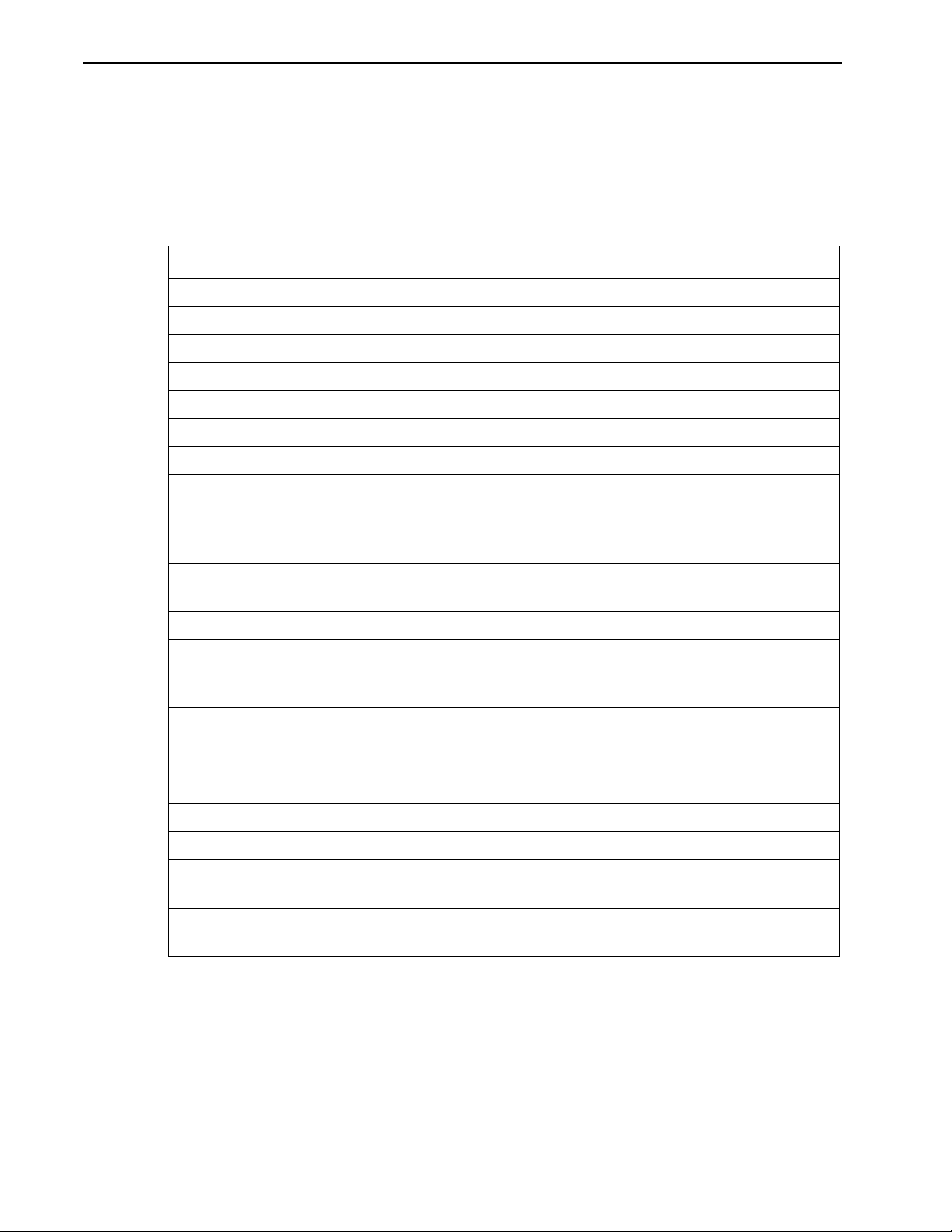
Line Control Characteristics
Control Method Contention method (point to point)
Operating Mode Half duplex (if modems are used, set to full duplex)
Synchronization Start-stop system
Data Rate 1200, 2400 or 4800 bits/second (bps)
Frame Contents ASCII (7bits)
Error Control Method VRC: Parity, LRC: BCC
Bit Transmission Order Priority is given to low order bits.
Transmission Intervals At each data generation. When a stream of information is
Priority Sequence Primary office: NEAX
Stop bit 1 bit or 2 bits
The characteristic s of the signals t ransmitted across t he communications lin k are as
follows:
Table 2-1 Line Control Characteristics
Item Conditions
transmitted to the NEAX continuously, an interval of 0.5
seconds or more should be given between messages. Each
message must be delimited by the EOT code.
Secondary Office: PMS
Error Control VRC: Even, odd or no parity.
LRC: (BCC) Exclusiv e OR of the message text, st arting after the
STX, and ending with (and including) the ETX.
Message Composition One message constitutes one record; SOH, TTB and ETB are not
used.
Message Length V aria ble length, maximum of 12 8 characters (includi ng STX and
ETX).
Electrical Interface EIA RS-232C electrical standard interface
Signal Form EIA RS-404
Interface Distance Maximum of 50 feet between the NEAX an d the PMS when not
using a modem.
Word Framing 10 bits (1 start, 7 data, 1 parity, 1 stop) or 11 bits (1 start, 7 data,
1 parity, 2 stop)
Page 4 NDA-30115 Revision 1.0
Page 15
Property Management System - Communication Interface Architecture
05H
‘1’
‘!’
SAUAENQ
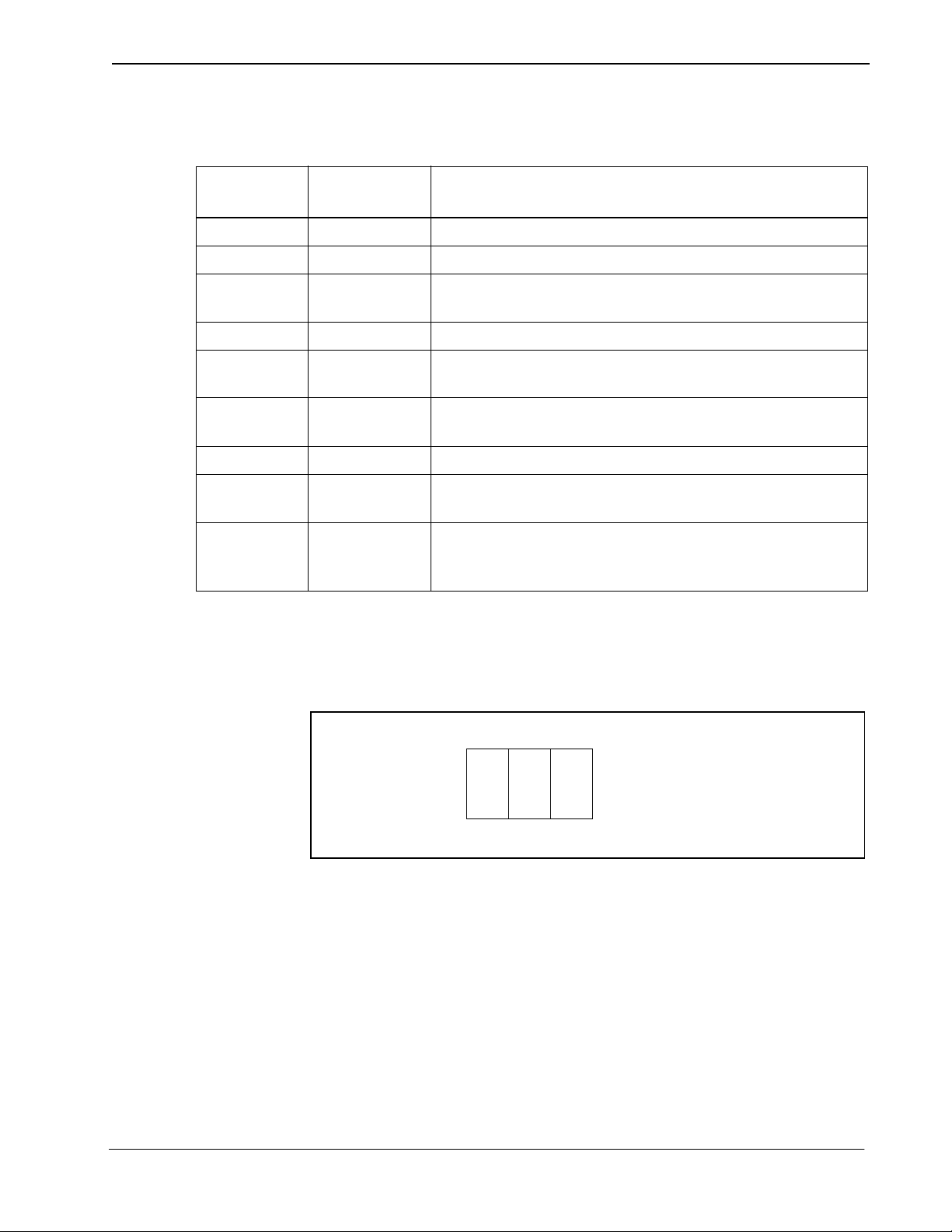
The control codes used for the message texts are:
Table 2-2 Control Codes
Control Code
STX 02 Indicates the start of a block.
ETX 03 Indicates the end of a block.
EOT 04 Indicates the end of transmission of a block or release of the
ENQ 05 Used to query other party for expected response.
ACK 06 Indicates the p ositive acknowledgmen t of an informat ion block
NAK 15 Indicates the negative acknowledgment of an information
DLE < 10, 3C Indicates the receiver interrupting to ask for sending rights.
DLE : 10, 7C Indicates the receiver interrupting to ask the sender to stop
DLE ? 10, 3F Used as the negative acknowledgment of block and indicates
Transmission Protocol
Hexadecimal
Value
Function
data link by the sender.
or start sequence.
block or start sequence.
transmission and to release the data link.
that the receiver temporarily cannot receive data from the
sender.
Before a message can be sent, a start sequence (also called a selecting sequence)
must be sent to urge the receiver to receive the data. Every transmission sequence
will begin with the sender sending a start sequence.
The start sequence is a three byte sequence:
012
Figure 2-1 Start Sequence
NDA-30115 Revision 1.0 Page 5
Page 16
Architecture Property Management System - Communication Interface
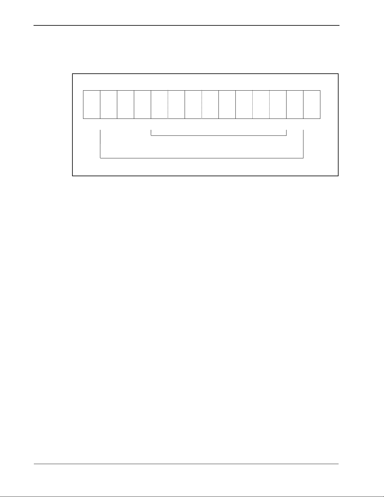
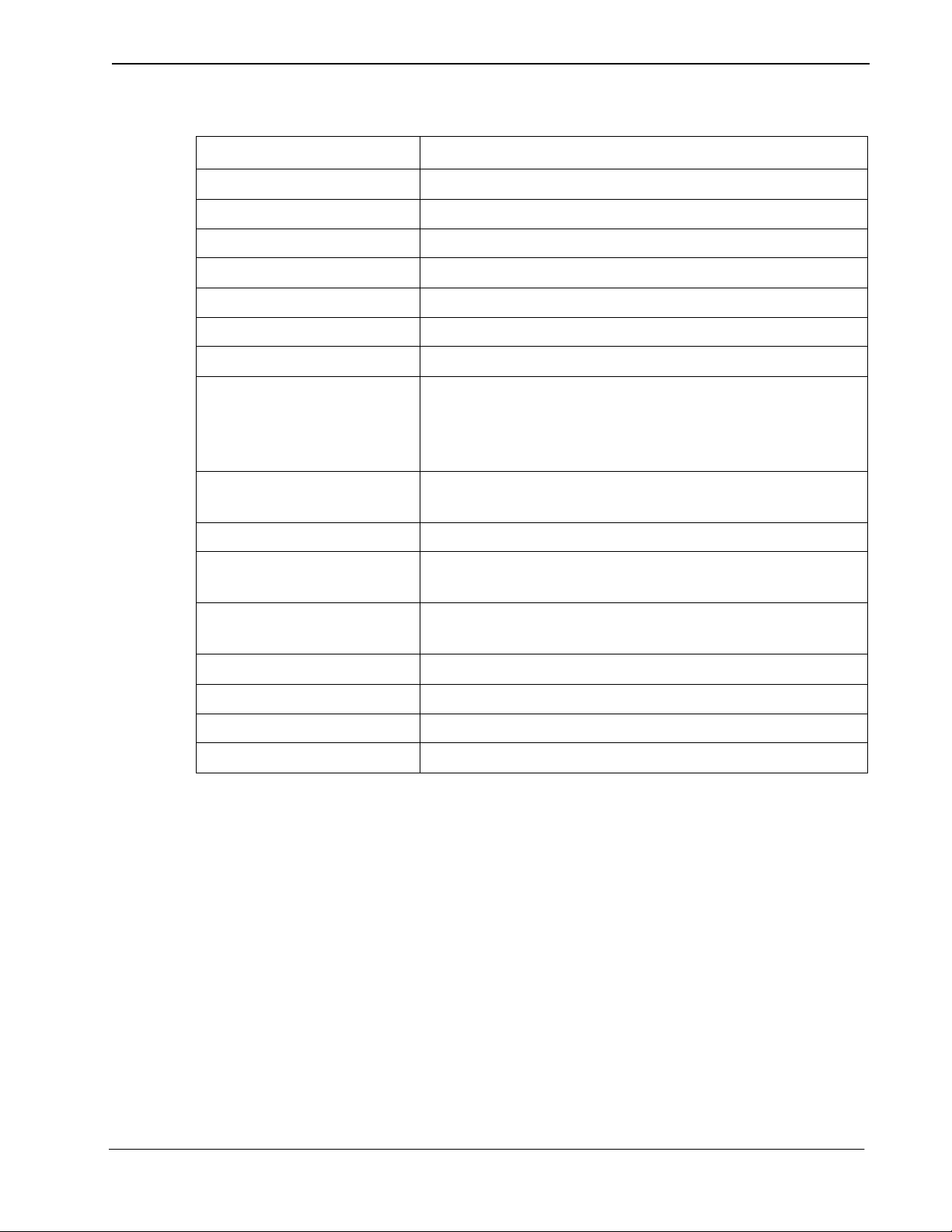
The messages (but not t he control code s or start seq uence) sent betw een the NEAX
and the PMS must have header and trailing sections as defined in the following
format:
01234 6 89
02H ‘1’ 03H xx‘!’ ...
STX SA UA EI FTC MSC FC Message ETX BCC
‘L’
Message Count Range
Block Check Code Range
Table 2-3 Base Message Format
The message format breaks down as follows:
• STX -- Start of text block. (One byte - 02H.)
• SA -- System Address. (O ne byte - ‘1’ [31H].)
• UA -- I/O Unit Address. (One byte - ‘!’ [21H].)
• EI -- Entry Index. (One byte - ‘L’ [4CH].)
• FTC -- Feature Code. (See below.) A list is provided in Appendix C, “Feature
Codes”.
• MSC -- Message Counter . This re presents the l ength of the message. The cou nt
of characters st arts at the FTC f ield an d ends at t he last ch aracter of the body o f
the message, not i ncluding the ETX. If t he ETX character doe s not immediatel y
follow the charac ter specified by the message counter, an invalid message is
assumed.
• FC -- Function Code. This sp ecifi es the indi vidua l operation a nd processing for
the feature designated by the Feature Code (FTC). A list is provided in
Appendix D, “Function Codes”.
• ETX -- End of text block. (One byte - 03H.)
• BCC -- Block Check Code. This is computed by an exclusive OR of the
message fr om the SA to the ETX (inclusive). Detection of an STX starts the
computation (but the STX is not included). Detection of an ETX stops the
computation (and the ETX is included). (One byte.)
Feature Codes range in valu e fr om 00 to FF (hex). These codes define th e “Major
Category Codes” for service features.
Codes from 80 to FF are used as “Violation Codes”. When a specific message
received from the PMS can not be processed for some re aso n, 80 (hex) is added to
the received Feature Code so that it will be handled as a Violation Code. If the
NEAX regards a text as a Violation Code, the system data of the NEAX may be
assigned so that a tex t of this type is re turned to the PMS. There fore, when the PMS
has received a Violation Code, provisions shoul d be made for the PMS to print out
this violation.
Page 6 NDA-30115 Revision 1.0
Page 17

Property Management System - Communication Interface Architecture
A Violation Code message will be sent to the PMS in the following cases:
• When the message counter does not match the number of characters received.
• When a station number not existing in the NEAX is specified in the message
data from the PMS.
• Upon rece ipt of an invalid Wake Up time (e.g. 25: 00).
Transmission Sequence
The sequence of transmit ting a message is slightly different for the PMS and
NEAX. However, both sequences follow the same outline.
The party which desires to send must first bid for sender rights. This is done by
sending the start sequence (see Figure 2- 1). On ce t he start sequence h as b een sent
and acknowledged, that party is now the “sender” and the other party is the
“receiver”. (Unless both parties have simultaneously sent a start sequence. If this
occurs, the PMS must relinquish sending rights to the NEAX.) The receiver must
then respond with an answer control code (ACK, NAK, DLE <, DLE :, DLE ?)
before the Sender Timer (see “Sender Timer” on page 10) expires.
If no answer control code is received, the sende r will resend the st art sequence and
again wait for an answer control code.
When an answer control code is received, the sender must respond before the
Receiver Timer (see “Receiver Timer” on page 10) expires. If the answ er control
code is an ACK, the sender must send the message. Again, the receiver must
respond with an answer control code before the Sender Timer expires.
To finish the transmission sequence (regardless of its success), the sender must
send an End Code (EOT) to release sending ri ght s. Once that is done, both parties
may begin the process over again by bidding for the sender rights.
In the trans mission sequence figures that follow, these m essage names are used:
Table 2-4 Message Names
Name Control Code Explanation
Start Sequence
Message
Query
End Code
Accept
Reject
No Answer
SA, UA, ENQ Bid for sender rights
STX, ..., ETX, BCC Actual message sent
ENQ Query for expected answer control code
EOT Release sender rights
ACK Positive acknowledgment
NAK Negative acknowledgment
<Nothing> Timer expired before an answer control
code was received
Contention
Interrupt
Abort
Pause
NDA-30115 Revision 1.0 Page 7
Start Sequence Simultaneous start sequences
DLE < Request to release sender rights
DLE : Demand to release sender rights
DLE ? Receiver’s queue full; please wait
Page 18
Architecture Property Management System - Communication Interface
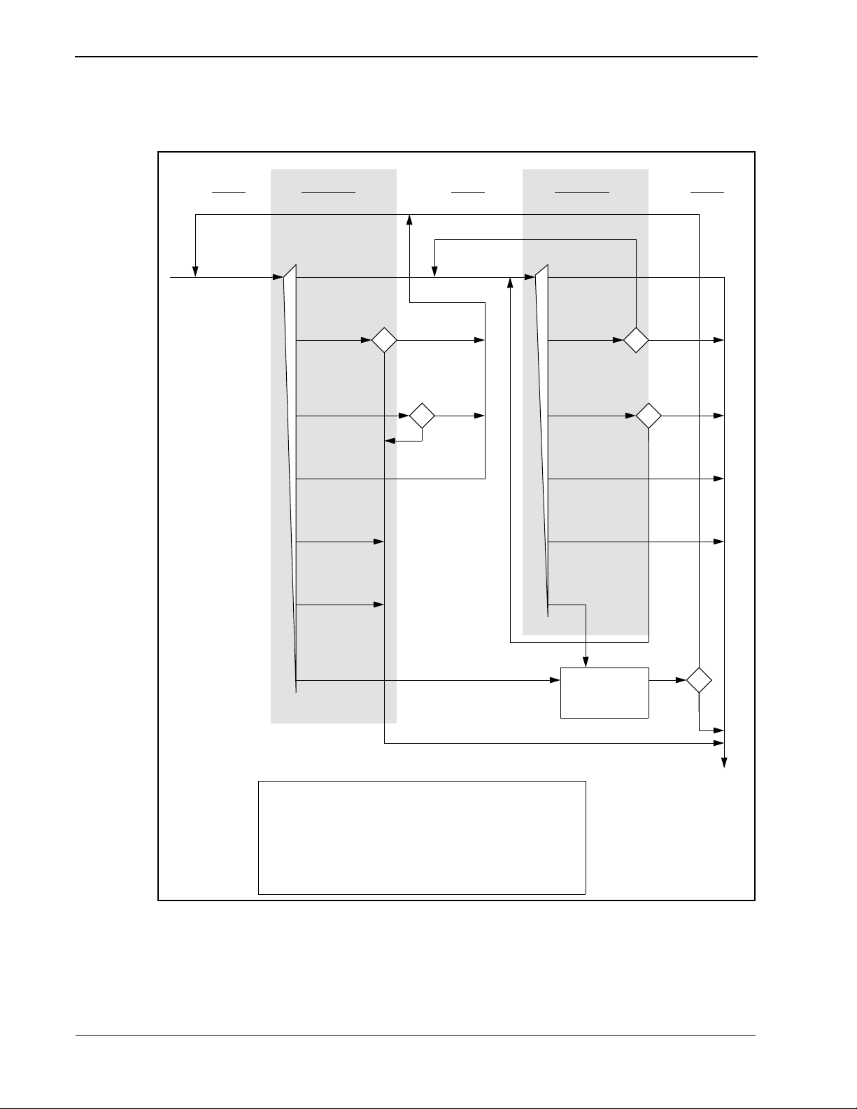
From the NEAX to the PMS
Send Receive ReceiveSend Send
Start
Sequence
Accept
Reject
No Answer
Contention
Interrupt
Abort
Pause
1
quit
quit
retry
retry
2
Message
Query
Accept
Reject
No Answer
Interrupt
Abort
Pause
Wait
1 second
retry
3
quit
4
retry
quit
retry
5
quit
End
Code
1 - Retry is 3 times; quit on 4th Reject.
2 - Retry is 15 times; quit on 16th No Answer.
3 - Retry is 3 times; quit on 4th Reject.
4 - Retry is 32 times; quit on 33rd No Answer.
5 - Retry is 3 times; quit on 4th Pause.
Figure 2-2 NEAX to PMS Protocol
Page 8 NDA-30115 Revision 1.0
Page 19

Property Management System - Communication Interface Architecture
From the PMS to the NEAX
Send Receive ReceiveSend Send
Start
Sequence
Accept
Reject
No Answer
Contention
Interrupt
Pause
1
continue
2
quit
Message
Query
Accept
Reject
No Answer
Interrupt
Pause
Wait
1 second
retry
3
4
retry
quit
quit
Wait
1 second
End
1 - Do not respond. Immediately cease send attempt and
Code
receive message from NEAX.
2 - Ignore Interrupt and send message if 8 messages in queue.
3 - Retry is 3 times; quit on 4th Reject.
4 - Retry is 32 times; quit on 33rd No Answer.
Figure 2-3 PMS to NEAX protocol
NDA-30115 Revision 1.0 Page 9
Page 20
Architecture Property Management System - Communication Interface
Timers
Cabling Considerations
The following timers are used to maintain data transmission:
Sender Timer
Upon sending a start sequence, message text or query, this timer begins counting
and stops counting upon rece iving a vali d answer contro l code. This timer is set to
one (1) second. If a ti meout occurs af ter the transmis sion of a start s equence, a start
sequence will be r esent up t o 1 5 time s. If a t imeout occurs duri ng the t ransmi ssion
of a message text or query, a query is sent up to 32 times.
Receiver Timer
Upon transmission of a positive acknowl edgment for a sta rt sequence or a messag e
text, this timer begins counting and stops counting upon receiving a message text
or an end code. This timer is se t to 35 seco nds. If a ti meout occurs, t he sender l oses
send rights.
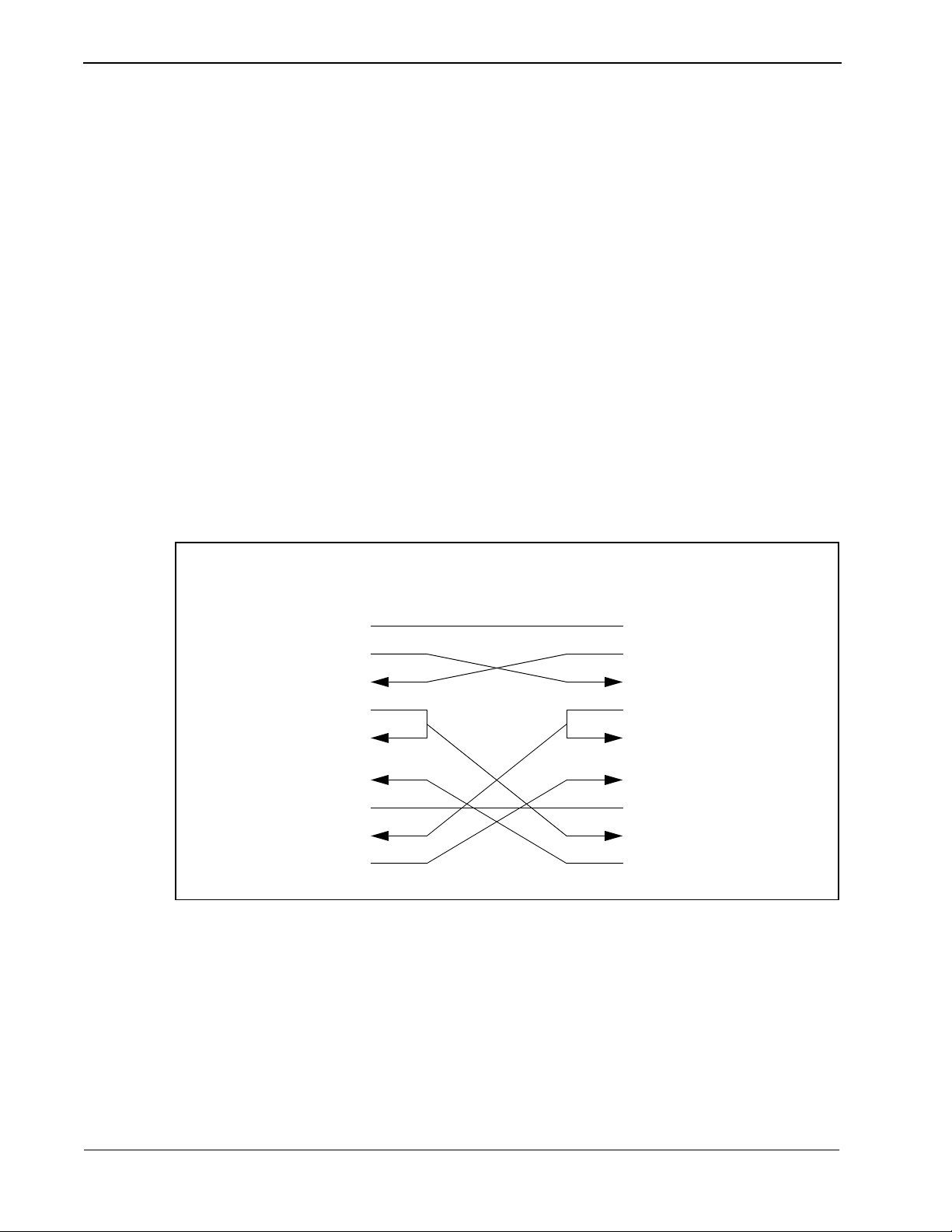
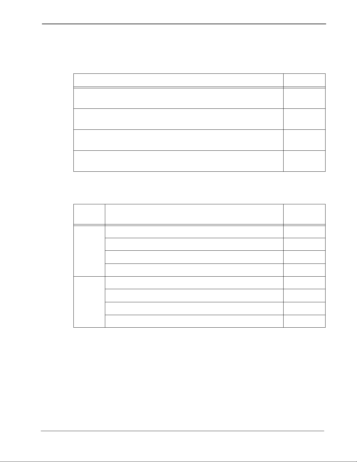
When the PMS is connected to the NEAX through a modem, the cab les should just
be “straight through” cables. There should be no crossing.
When the PMS is directly connected to the NEAX, use the following pin
assignments:
NEAX PMS
Pin No. Signal Cable
1FG
2
3
4
5
6
7
8
20
SD
RD
RS
CS
DR
SG
CD
ER
Figure 2-4 Direct Connection Pin Assignments
Bisynchronous (BSC) Transmi ssion
Line Control Characteristics
The characteristic s of the signals t ransmitted across t he communications lin k are as
follows:
Signal Pin No.
FG
SD
RD
RS
CS
DR
SG
CD
ER
1
2
3
4
5
6
7
8
20
Page 10 NDA-30115 Revision 1.0
Page 21
Property Management System - Communication Interface Architecture
Table 2-5 Line Control Characteristics
Item Conditions
Control Method Contention method (point to point)
Operating Mode Half duplex (if modems are used, set to full duplex)
Synchronization Synchronous
Data Rate 4800 or 9600 bits/second (bps)
Frame Contents EBCDIC
Error Control Method CRC-16 (X16 + X15 + X2 + 1)
Bit Transmission Order Priority is given to low order bits
Transmission Intervals At each data generation. When a stream of information is
transmitted to the NEAX continuously, an interval of 0.5
seconds or more should be given between messages. Each
message must be delimited by the EOT code.
Priority Sequence Primary office: NEAX
Secondary Office: PMS
Transfer Mode Non-transparent mode
Message Composition One message constitutes one record; SOH, ITB and ETB
are not used. Only the non-transparent mode is used.
Message Length Variable length, maximum of 128 characters (including
STX and ETX).
Electrical Interface RS-232C electrical standard interface
Signal Form RS-404
Interface Distance 50 feet
Word Framing 10 bits or 11 bits
NDA-30115 Revision 1.0 Page 11
Page 22
Architecture Property Management System - Communication Interface
The control codes used for the message texts are:
Table 2-6 Control Codes
Control Code
Hexadecimal
Value
Function
SYN 32 Synchronization code.
STX 02 Indicates the start of a block.
ETX 03 Indicates the end of a block.
ENQ 2D Used as the start sequence code. It indicates a reception
request to the other side and a request to answer an information block just sent.
EOT 04 Indicates the end of transmission of a block or release of
the data link by the sender.
ACK0 10, 70 Used alternately, these indicate the positive acknowledgACK1 10, 61
ment of an information block or a start sequence.
NAK 3D Indicates the negative acknowledgment of an informa-
tion block or a start sequence.
WACK 10, 6B Used as the positive acknowledgment of an information
block or start sequence and indicates that the receiver
temporarily cannot receive data from the sender.
TTD 02, 2D Indicates that the sender cannot transmit the next infor-
mation block after the receipt of the answer to the previ-
ous information block sent from the receiver.
R VI 10, 7C Indicates the positive acknowledgment of an information
block and asks the sender for sending rights.
PAD-L 55 Indicates the absolute beginning of the entire informa-
tion block.
PAD-T FF Indicates the absolute ending of the entire information
block.
Page 12 NDA-30115 Revision 1.0
Page 23
Property Management System - Communication Interface Architecture
Transmission Protocol
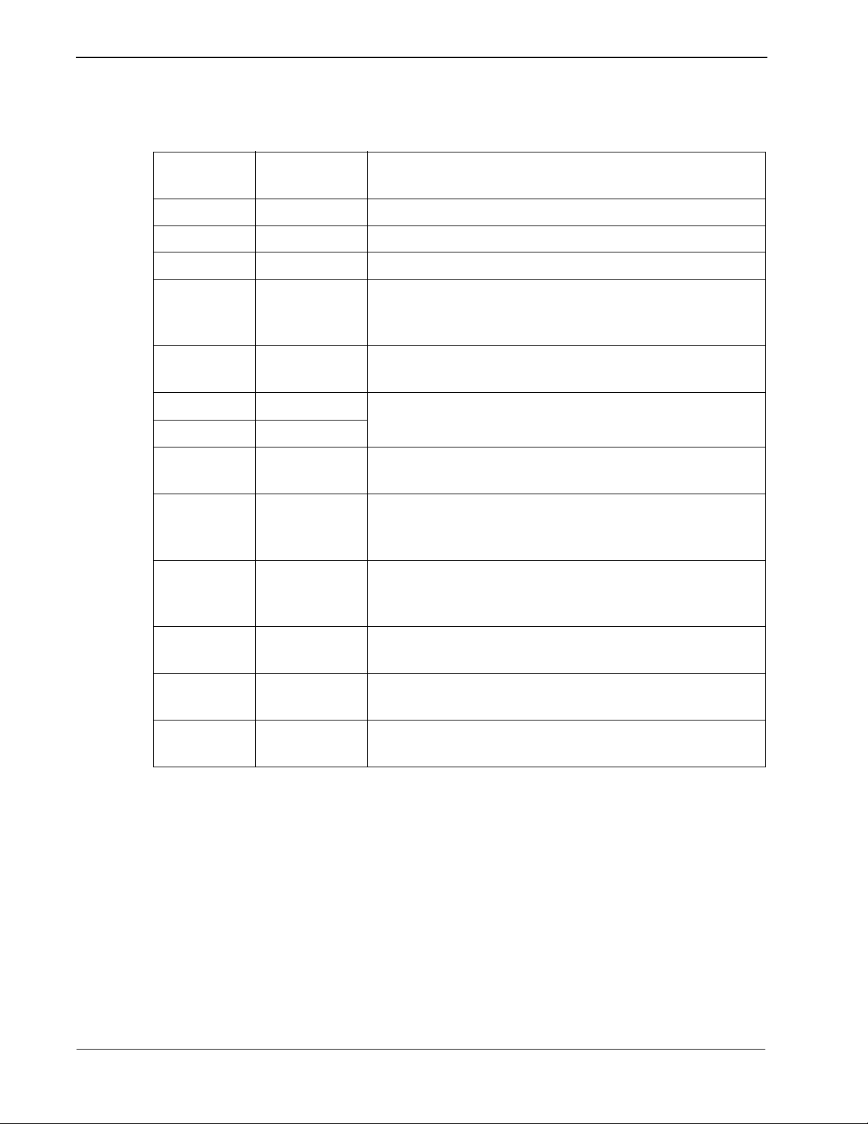
The messages sent between t he NEAX and the P MS must ha ve header and tra iling
sections as defined in the following format:
PAD-LSYN SYN SYN
Figure 2-5 Base Message Format
The elements of the message is as follows:
• PAD-L -- The leading pad character. (One byte - 55H.)
• SYN -- Synchronizatio n character . At least thr ee of these shoul d be transmitt ed.
(One byte each - 32H.)
02H 03H xx
STX Data ETX CRC PAD-T
FFH32H55H 32H 32H
Cyclic Redundancy Check Area
• STX -- Start of text block. (One byte - 02H.)
• Data -- The message data is describe below in Figure 2-6.
• ETX -- End of text block. (One byte - 03H.)
• CRC-- Cyclic Redundanc y Che ck. Thi s is compute d b y an e xclusive OR of the
message fr om the SA to the ETX (inclusive). Detection of an STX starts the
computation (but the STX is not included). Detection of an ETX stops the
computation (and the ETX is included). (One byte.)
• PAD-T -- The trailing pad character. (One byte - FFH.)
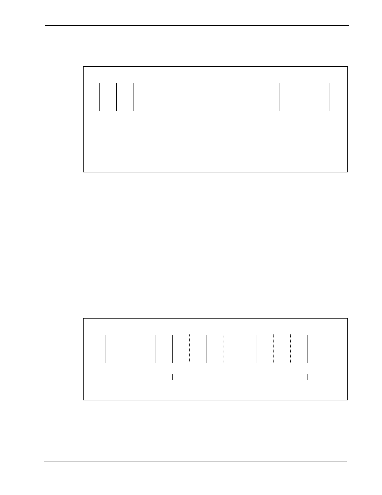
The message data is defined as follow:
02H ‘1’ 03H‘!’ ...
STX SA UA EI FTC MSC FC Message ETX
‘L’
Message Count Range
Figure 2-6 Message Data Format
NDA-30115 Revision 1.0 Page 13
Page 24

Architecture Property Management System - Communication Interface
The message format breaks down as follows:
• STX -- Start of text block. (One byte - 02H.)
• SA -- System Address. (O ne byte - ‘1’ [31H].)
• UA -- I/O Unit Address. (One byte - ‘!’ [21H].)
• EI -- Entry Index. (One byte - ‘L’ [4CH].)
• FTC -- Feature Code. (See below.) A list is provided in Appendix C, “Feature
Codes”.
• MSC -- Message Counter . This re presents the l ength of the message. The cou nt
of characters st arts at the FTC f ield an d ends at t he last ch aracter of the body o f
them message, not including the ETX. If the ETX character does not
immediately follow the character specified by the message counter, an invalid
message is assumed.
• FC -- Function Code. This sp ecifi es the indi vidua l operation a nd processing for
the feature designated by the Feature Code (FTC). A list is provided in
Appendix D, “Function Codes”.
• ETX -- End of text block. (One byte - 03H.)
Feature Codes range in valu e fr om 00 to FF (hex). These codes define th e “Major
Category Codes” for service features.
Codes from 80 to FF are used as “Violation Codes”. When a specific message
received from the PMS can not be processed for some re aso n, 80 (hex) is added to
the received Feature Code so that it will be handled as a Violation Code. If the
NEAX regards a text as a Violation Code, the system data of the NEAX may be
assigned so that a tex t of this type is re turned to the PMS. There fore, when the PMS
has received a Violation Code, provisions shoul d be made for the PMS to print out
this violation.
A Violation Code message will be sent to the PMS in the following cases:
• When the message counter does not match the number of characters received.
• When a station number not existing in the NEAX is specified in the message
data from the PMS.
• Upon rece ipt of an invalid Wake Up time (e.g. 25: 00).
Page 14 NDA-30115 Revision 1.0
Page 25

Property Management System - Communication Interface Architecture
Transmission Sequence
Table 2-7 Data Transmission Sequence (1 of 2)
Status ENQ STX
Neutral (A) a: ACK0 ->
(B)
b: NAK ->
(A)
c: ENQ ->
(D)
Waiting for
STX (B)
(ACK last
received) ->
-> (C)
(B)
Waiting for
ETX, CRC
(C)
f: NAK ->
(B)
g: EOT ->
(A)
Waiting for
ACK after
start
sequence
f: ENQ ->
(D)
g: EOT ->
(A)
d: ENQ ->
(D)
e: EOT ->
(A)
(D)
ETX,
CRC
h: ACK0/1
i: NAK
c: RVI
j: EOT
-> (A)
d: ENQ ->
(D)
e: EOT ->
(A)
ACK0/
ACK1
Message ->
(E)
j: EOT ->
(A)
NAK
f: ENQ ->
(D)
g: EOT ->
(A)
Waiting for
ACK after
message (E)
NDA-30115 Revision 1.0 Page 15
d: ENQ ->
(D)
e: EOT ->
(A)
d: ENQ ->
(D)
e: EOT ->
(A)
d: ENQ ->
(D)
e: EOT ->
(A)
k: Message
-> (E)
l: EOT ->
(A)
m: Message -> (E)
j: EOT ->
(A)
Page 26

Architecture Property Management System - Communication Interface
Table 2-8 Data Transmission Sequence (2 of 2)
Status EOT TTD WACK (Timeouts)
(Transmis-
sion Request)
Neutral (A) ENQ -> (D)
Waiting for
STX (B)
-> (A) d: NAK ->
(B)
EOT -> (A)
(25 sec)
e: EOT ->
(A)
Waiting for
ETX, CRC
-> (A) EOT -> (A)
(25 sec)
(C)
Waiting for
ACK after
start
sequence
-> (A) d: ENQ ->
(D)
e: EOT ->
(A)
d: ENQ ->
(D)
e: EOT ->
(A)
f: ENQ ->
(D)
g: EOT ->
(A)
(D)
Waiting for
ACK after
message (E)
-> (A) d: ENQ ->
(D)
e: EOT ->
(A)
d: ENQ ->
(D)
e: EOT ->
(A)
f: ENQ ->
(D)
g: EOT ->
(A)
(3 sec)
Notes:
• a: Preparation for reception complete.
• b: Reception impossible.
• c: Requests for preparation for reception (the PMS should not request this).
• d: Transmitted up to 21 times.
• e: Aborted at 22nd time.
• f: Transmitted up to 7 times.
• g: Aborted on the 8th time.
• h: Message is received normally and preparation for ne xt rece ption is complete.
• i: Error found in message.
• j: Interruption.
• k: Information to be transmitted is present.
• l: Information to be transmitted is absent.
• m: Retransmission of message.
Page 16 NDA-30115 Revision 1.0
Page 27
Property Management System - Communication Interface Architecture
Timers and Counters
Retransmission Counts
Table 2-9 Retransmission Counts
Meaning Count
The number of retransmissions of the start sequence when there is no
answer after transmitting the start sequence.
The number of retransmissions of the start sequence when NAK is
received after transmitting the start sequence.
The number of transmitting ENQs when WACK is received after the
transmission of an information block
The number of transmitting ENQs when there is no answer after the
transmission of an information block. (3 second intervals)
Timer Values
Table 2-10 Timer Values
Party Starting Condition
7
7
15
7
Timer value
(seconds)
NEAX Waiting for a start sequence answer. 1
Waiting for STX after transmitting the start sequence ACK. 20
Waiting for data reception complete (waiting for ETX, CRC). 20
Waiting for an answer after the transmission of a message. 1
PMS Waiting for a start sequence answer. 3
Waiting for STX after transmitting the start sequence ACK. 25
Waiting for data reception complete (waiting for ETX, CRC). 25
Waiting for an answer after the transmission of a message. 3
NDA-30115 Revision 1.0 Page 17
Page 28
Architecture Property Management System - Communication Interface
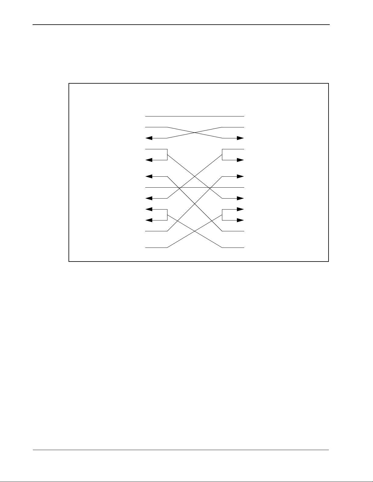
Cabling Considerations
When the PMS is connected to the NEAX through a modem, the cab les should just
be “straight through” cables. There should be no crossing.
When the PMS is directly connected to the NEAX, use the following pin
assignments:
NEAX PMS
Pin No. Signal Cable
Signal Pin No.
1FG
2
3
4
5
6
7
8
15
17
SD
RD
RS
CS
DR
SG
CD
ST
RT
2
FG
SD
RD
RS
CS
DR
SG
CD
ST
RT
1
2
3
4
5
6
7
8
2
15
17
20
24
ER
ST
1
Figure 2-7 Direct Connection Pin Assignments
ER
ST
20
1
24
Page 18 NDA-30115 Revision 1.0
Page 29

Property Management System - Communication Interface Message Descriptions
Chapter 3 Message Descriptions
There are several message groups:
• Data Link Maintenance Messages
• Maid Status
• Message Waiting Lamp Control
• Restriction Control
• Check In/Check Out (Model 60)
• Check In/Check Out (Model 90)
• Wake Up/Group Announcement
• Room Move/Swap/Copy (Model 60)
• Room Data Change
• Extension Report
• Room Recovery (Model 60)
• Room Recovery (Model 90)
• Direct Data Entry (Model 90)
• Extension Connection
Each message group will be described briefly in the following sections.
The NEAX equates rooms wit h extensions, one e xtension per ro om. The exception
to this is the suite room feature. When this feature is activated in the NEAX, a
primary extension represents a group of extensions in one or more rooms. For a
suite room, the PMS should reference only the primary extension in its messages
to the NEAX. All associated extensions will inherit the attributes of the primary
extension and should effectively be ignored by the PMS.
Data Link Maintenance
These are the messages used by the PMS and NEAX to maintain communication.
The PMS must regularly send Nop Test messages with an interval of no more than
60 seconds, and no less than 50 0 milliseconds, between each message . The NEAX
will immediately respond with either a Nop Test Normal Answer, under normal
conditions, or a Nop Test Recover Answer, i f a database reco very for the NEAX i s
needed.
• Nop T es t Normal An swer -- Whene v er a Nop Test message is sent by th e PMS,
the NEAX responds by sending this message, unless the NEAX has just
finished an error recovery.
• Nop Test Recover Answer -- If the NEAX has been performing an error
recovery , this message is sent in response to the Nop T est in the place of the Nop
Test Normal Answer message.
NDA-30115 Revision 1.0 Page 19
Page 30

Message Descriptions Property Management System - Communication Interface
• Recovery Start Report -- After r eceiving the Nop Test Recover Answer
message, the PMS must download NEAX database informat ion (see “Room
Recovery (Model 60)” on page 27 and “Room Recovery (Model 90)” on page
28). This message notifies the NEAX of the incoming download.
• Recovery End Report -- Repo rts to the NEAX that the PMS database do wnload
is complete.
• Data Link Release Request -- Used by either system to request a temporary
release of the data link.
• Data Link Release Conf irmation -- Reply to t he above message to ackno wledge
data link release request.
• Extension Number Request - - Used by the PMS to request the current status of
extension numbers.
• Nop Test -- Under the standard protocol the PMS must send this message at
least every 60 seconds, but not less than 500 milliseconds, to demonstrate that
communication has been maintained.
Data Link Failure
Either system may recognize a loss of communication by one or more of the
following events:
• Lack of system traffic for a 60 second interval: the Nop Test message from the
PMS and the Nop Test Answer message (either Normal or Recover) from the
NEAX insure that at least one message should be received less than every 60
seconds.
• Detection of hardware problems within the physical data. Note that the NEAX
will put EIA pin number 6 (Data Set Ready) into the off state, indicating data
set not ready, when the data link has been effectively turned off in the NEAX,
either for maintenance or because of repeated, excessive errors.
• Excessive protocol errors (NAK’ed transmission, ENQ’s with no ACK/ NAK
response).
• Other conditions, su ch as una v ailab ility of buf f ers or queui ng capabil ity, which
result in an implied status change message which cannot be communicated to
the other system.
• Release of the data link requested and confirmed.
A data link failure will necessitate a database room exchange recovery procedure
only if any impl ied stat us change cannot b e communicat ed to t he other system and
cannot be queued for later transmission. If no messages have been lost, and can
instead be retransmitted, no database recovery is necessary.
Page 20 NDA-30115 Revision 1.0
Page 31

Property Management System - Communication Interface Message Descriptions
Release for Maintenance
NEAX Operations During Loss of Communication
Either system may request a temporary release of the data link for maintenance
purposes by transmitting a Da ta Link Release Request message to the oth er system.
The receiving system will perform any necessary processing and return the Data
Link Release Confirmation message as soon as possible.
During the NEAX maintenance, the PMS may continue to send Nop Test
messages, provided that EI A pin 6 (Data Set Ready) from the NEAX is in the “on”
condition. The NEAX will turn on the EIA pin 6 “on” and respond to Nop Test
messages w hen maintenance is completed.
While the data link is release on request of the PMS, the NEAX will continue to
attempt to read Nop Test messages from the PMS. The PMS may set EIA pin 20
(Data Terminal Ready) to the “off” condition to indicate t hat reading should not be
attempted.
When EIA pin 20 is in the “on” state and a Nop Te st mess age is recei ved fr om the
PMS, the NEAX will assume that PMS maintenance has ended and that
communication can be resumed.
The NEAX will continue to suppor t the ba sic te lecommuni catio ns f unctio ns if the
data link or PMS become unavailable. Upon detection of a data link failure, the
NEAX will automatically switch to the “Link Failed Mode” to perform the
following tasks:
Recovery from Loss of Communication
• Enable Check In and Check Out on the Attendant Console and Front Desk
Terminal.
• Continue support of Message Waiting and/or Controlled Restriction if both
features are active in the NEAX.
In the event of a PMS failure, it is assumed that Check In and Check Out must be
done manually and entered into the PMS syst em at a later time. The PMS shou ld
not resume transmission of the Nop Test message and attempt to reestablish
communication until the database has been brought up to date. This prevents the
transmission of incorrect data prematurely through the database recovery
procedure.
In cases where the PMS has remained operational during a data link failure, the
PMS will continue to attempt sending Nop Test messages. A Nop Test Answer
message (either Normal or Recover) from th e NEAX will indicate that
communication has been reestablished.
A Nop Test Normal Answer message indicates that the NEAX has had no status
change during the data link failure period and has automatically switched back to
the normal operating mode of an active data link.
A Nop Test Recover Answer me ssage indica tes t hat t he NEAX has fai led an d that
status memory has been initialized for each room with the following:
• Room Status is Occupied (Checked In),
• Controlled Restriction Level is set to the preassigned restriction,
• Message Waiting Lamps are off,
• Wake Up times are cleared.
NDA-30115 Revision 1.0 Page 21
Page 32

Message Descriptions Property Management System - Communication Interface
Maid Status
These messages are u sed by the NEAX to c ommunicate the a ctions of th e cleaning
personnel. If th e message i s designa ted “Model 90” then that message is only used
by the Model 90 version. The other messages are used by both versions.
• Cleaning Start (Guest)
• Cleaning End (Guest)
• Inspection End (Guest)
• Out of Order (Guest)
• Cleaning Start (Administration)
• Cleaning End (Administration)
• Inspection End (Administration)
• Guest Room 1 (Model 90)
• Guest Room 2 (Model 90)
• Guest Room 3 (Model 90)
• Guest Room 4 (Model 90)
• Guest Room 5 (Model 90)
• Guest Room 6 (Model 90)
• Guest Room 7 (Model 90)
Note:
This message was not previously defined in NEAX2400 IMS Hotel System PMS
Interface Specification.
• Negative Answer (Model 90)
• Positive Answer (Model 90)
• Administration 1 (Model 90)
• Administration 2 (Model 90)
• Administration 3 (Model 90)
• Administration 4 (Model 90)
For an expanded explanation of how the NEAX treats maid status information,
refer to Appendix A, “Room Status”.
Page 22 NDA-30115 Revision 1.0
Page 33

Property Management System - Communication Interface Message Descriptions
Message Waiting Lamp Control
These messages are us ed to control th e message waiting lamp on an extension. The
message waiting lamp is use d to notify a guest about th e existence of text message s.
If the message is designated “Model 90” then that message is only used by the
Model 90 version. The other messages are used by both versions.
When the NEAX is configured to use t he suite room featur e, the primary extensi on
represents all extensions in that suite. Th erefore, a message set to the primary
extension controls the message waiting lamps on all exte nsions in that suite.
• MWL On -- This message is sent by the PMS to turn on a message waiting lamp.
• MWL Off -- This message is sent by the PMS to turn off a message waiting
lamp.
• MWL On -- This message is sent by the NEAX to noti fy the PMS that a
message waiting lamp has been turned on.
• MWL Off -- This message is sent by the NEAX to notify the PMS that a
message waiting lamp has been turned off.
• MWL Status -- This message is sent by the PMS. (Model 90)
• MWL On (FDT) -- This message is sent by the NEAX to notify the PMS that a
message waiting lamp has been turned on by the front desk. (Model 90)
• MWL Off (FDT) -- This mes sage is sent b y the NEAX to notify the PMS tha t a
message waiting lamp has been turned off by the front desk. (Model 90)
Restriction Control
There are two messages. They are identical except that one is originated by the
PMS, the other by the NEAX. Each message simply transmits the restriction code.
Both the Model 60 and the Model 90 version use these messages.
Check In/Chec k Out (Mode l 60)
These messages do not represent unique feature s as such, but are a conven ient tool
for activating a sequence of functions commonly performed when a guest checks
in or out of a room. With one exception, al l of these message s are used exclusive ly
for Model 60. The sole exceptio n is Check Out Outgoing Call Report, whi ch is also
used by Model 90.
When the NEAX is configured to use t he suite room featur e, the primary extensi on
represents all extensions in that suite. Th erefore, a message set to the primary
extension controls the status of all extensions in that suite.
• Check In 1 -- Sets the Room Status to Stay and cancels Room Cut-Off. This
message is sent by the PMS. This message should not be used. Use Check In 3
instead.
• Check Out -- Sets the Room Status to Out and sets Room Cut-Of f. This message
is sent by the PMS.
NDA-30115 Revision 1.0 Page 23
Page 34

Message Descriptions Property Management System - Communication Interface
• Check Out Me ssage Waiting Lamp Off Repo rt -- This message is sent by the
NEAX to report that the Message Category “Front” of that specific guest room
is Off.
• Check Out Message Waiting Lamp On Report -- This me ssage is sent by the
NEAX to report that the Message Category “Front” of that specific guest room
is On.
• Check In 2 -- Same as Check In 1, but also sets the Language and Room Stay.
This message should not be used. Use Check In 3 instead.
• Check In 3 -- Same as Check In 2, but also sets the Guest Name and Group
Number.
• Check Out Outgoing Call Report -- The NEAX sends this message if, after
receiving a check out message from the PMS, it d etermines that the guest
extension is engaged in an outgoing call.
• Check Out Message Waiting Report -- This me ssage is gene rated b y the NEAX
to report the status of waiting messages.
Check In/Chec k Out (Mode l 90)
These messages do not represent unique feature s as such, but are a conven ient tool
for activating a sequence of functions commonly performed when a guest checks
in or out of a room. All of these messages ar e used exclusively for Model 90. Ther e
is also the addition of the Check Out Outgoing Call Report message which is
technically a Model 60 message, but is available for Model 90.
When the NEAX is configured to use the suite room featur e, the primary extensi on
represents all extensions in that suite. Th erefore, a message set to the primary
extension controls the status of all extensions in that suite.
• Check In -- This message is sent b y the PMS to notify the NEAX of a check in.
This cancels Room Cut-Off.
• Check Out -- This message is sent by the PMS to notify the NEAX of a check
out.
• Check In Cancellation -- This message is sent by the PMS. It cancels a
previously sent check in message. The room status is set to “Vacant.”
• Check Out Cancellation -- This message is sent by the PMS. It cancels a
previously s ent check out message. Unde r some circu mstances t he NEAX may
fail to perform this function which means that the guest must be checked in
again.
• Room Change -- This message is sent by the PMS to notif y the NEAX of a guest
room change.
• Provisional Check In -- This is a pro visional check in message generate d by the
NEAX. The room status is set to “Stay” and Room Cut-Off is cancelle d.
• Provisional Check Out -- Thi s is a pro v isio nal che ck out mess age gene rate d b y
the NEAX. If maid status is not performed, room status is set to “Vacant;” if
maid status is performed, room status is set to “Out.”
• Check Out Message Waiting Report -- This me ssage is gene rated b y the NEAX
upon receiving a check out message to report the status of waiting messages.
Page 24 NDA-30115 Revision 1.0
Page 35

Property Management System - Communication Interface Message Descriptions
W ake Up/Group Announcement
These messages allow for the management of wake up calls and group
announcements. Both the Mo del 60 a nd t he Model 90 version use these mess age s.
• Wake Up Setting (NEAX) -- This message is sent by the NEAX to notify the
PMS that a wake up call has been set.
• Wake Up Cancellation (NEAX) -- This message is sent by the NEAX to notify
the PMS that a wake up call has been cancelled.
• Wake Up Execution Result -- This message is sent by the NEAX to report the
results of the wake up call.
• W ake Up Setting(PMS) -- This message is sent by the PMS to set a wake up c all.
• Wake Up Cancellation (PMS) -- This message is sent by the PMS to cancel a
wake up call.
• Group Announcement Setting (NEAX) -- This messa ge is sent by the NEAX to
notify the PMS that a group announcement has been set.
• Group Announcement Cancellation (NEAX) -- This message is sent by the
NEAX to notify the PMS that a group announcement has been cancelled.
• Group Announcement Execution Result -- This message is sent by the NEAX
to report the results of a group announcement.
• Group Announcement Setti ng (PMS) -- This messa ge is sent b y the PMS to set
a group announcement.
• Group Announcement Cancellat ion (P MS) -- This message is sent b y t he PMS
to cancel a group announcement.
Room Move/Swap/Cop y (Model 60)
These messages are used to transfer room information. All of these messages are
used exclusively for Model 60. The messages are:
• Room Move -- This takes the data for one room and moves it to another room.
This will leave the second extension’s maid status unchanged, cancels Room
Cut-Off and sets all other data to that of the first extension. The first extension’s
maid status is set to ‘1’, Room Cut-Off is set, Do Not Disturb and Message
Waiting is reset, Wake Up is cancelled, Language is set to “Undefined” and
Guest Name and Group Number are cleared.
• Room Swap -- This takes the data for one room and moves it to another room,
while taking the other room’s data and moving it to the first room.
• Room Copy -- This exactly copies the data for one room to another room
without changing the data for the first room. The PMS should take care to be
consistent in the manner in which this message is used. If the PMS sends a
Room Copy message after che ck in, it should sen d a Room Copy message aft er
check out.
NDA-30115 Revision 1.0 Page 25
Page 36

Message Descriptions Property Management System - Communication Interface
Room Data Change
These messages are used to change the room information w hile a guest is st ill
checked in. Messages designated “Model 60” are only used by the Model 60
version; “Model 90” are only used by the Model 90 versio n. Messages with neit her
designation may be used by either version. The messages are as follows:
• Room Data Change 60 -- This is used to change room data after check in. This
message is sent by the PMS. (Model 60)
• Group Formation -- Thi s i s use d when adding a guest to a group or cha nging a
guest’s group after check in. This message is sent by the PMS.
• Group Cancellation -- This is used to remove a guest from a group after check
in. This mes sage is sent by the PMS.
• Reservation Setting -- This is used to set reservation for a guest room. The
reservation information is cleared by check in processing or when the room
status becomes “Vacant” or “Out of Order”. (Model 60)
• Reservation Cancellation -- This cancels guest room reservation. (Model 60)
• Guest Name Change -- This is used to change the guest name after check in.
This message is sent by the PMS. (Model 60)
Extension Report
• Room Data Change 90 -- This is used to change room data after check in. This
message is sent by the PMS. (Model 90)
• Room Status Change -- This is used to change the room status and/or the
cleaning status of the room after check in. This message is sent by the PMS.
(Model 90)
• Room Key Status Change -- This is used to change the room key status after
check in. This message is sent by the PMS. (Model 90)
These messages are used by the NEAX to report to the PMS when an extension has
been removed or a new extension has been added. Both the Model 60 and the
Model 90 version use these messages.
Page 26 NDA-30115 Revision 1.0
Page 37

Property Management System - Communication Interface Message Descriptions
Room Recovery (Model 60)
These messages are used by the PMS to update the database in the Model 60
version. These messa ges will usually only be se nt if re quested by the NEAX us ing
the Nop Test Recover Answer message. However, the PMS may, if necessary,
initiate a recovery with a d irect request from the NEAX.
Before any recovery messages can be sent, the PMS must first send a Recovery
Start Report message . After all informa tion about rooms has been sent by re covery
messages, a Recovery End Report message must be sent. Both of these messages
are defined in the Data Link Maintenance section.
The recovery messages are grouped into three sets of four messages. Within each
set of four messages, the format of the mes sages is identical, except for the
Function Codes, which specify the message. Each set of messages contains more
fields (and can therefore convey more information) than the preceding set.
Each set of four messages is composed of two pairs of messages. The PMS must
use the same set of recovery message s during t he recove ry period . The firs t pair of
messages is used when the PMS, in normal operation (i.e. not error recovery),
needs to update the informati on on a given extension. The second pair of messa ges
is used during recovery. This pair will only be used in response to the NEAX
sending a Nop Test Recover Answer or Recovery Request message.
The first message (of either pair) is used by the PMS as an update/ request for
information on an extension. If a field contains a valid entry, the NEAX database
is updated; if the field is entirely filled with NULL (00H) characters, it is a request
for the NEAX to send the value from the NEAX databas e. Th e s econ d message is
the response from the NEAX to the PMS.
• Room Image Set 1 -- Cont ains t he fo llo wi ng f ield s: Ext ension , Vacancy, MWL
and Restriction Level.
• Room Imag e Set 2 -- In addi tion to the above fields, t he following are added:
Room Stay, Reserve, Language, Cleaning Status and Wake Up.
• Room Image Set 3 -- In addition to th e abov e f ields, Group Number and Group
Announcement are added.
NDA-30115 Revision 1.0 Page 27
Page 38

Message Descriptions Property Management System - Communication Interface
Room Recovery (Model 90)
These messages are used by the PMS to update the database in the Model 90
version after a failure recovery. These messages will usually only be sent if
requested by the NEAX using the Nop Test Recover Answer message. However,
the PMS may, if necessary, initiate a recovery with a direct request from the
NEAX.
Before any recovery messages can be sent, the PMS must first send a Recovery
Start Report message . After all informa tion about rooms has been sent by re covery
messages, a Recovery End Report message must be sent. Both of these messages
are defined in the Data Link Maintenance section.
• Room Data Report -- Once Recovery has been requested by the NEAX, the
PMS uses this message to report the data for each room.
• Guest Room Secretary Telephone -- This message is used to rec over data for a
secretary telephone.
• Connecting Room -- If any rooms are connecting, this message is used to
establish the relationship.
• Message Status Report -- This reports the status of the Message Waiting Lamp.
• Wake Up -- Any wake up da ta is reported by this message.
Direct Data Entry (Model 90)
These messages are used to send numeric information from the NEAX to the PMS.
An employee provides t his inf ormation b y enteri ng an acc ess code at a gue st room
telephone. Then the NEAX captures all numeric input following the access code
and sends the digits to the PMS.
The NEAX expects to receive a response to this message within 30 seconds. If no
response is sent, or a Negative Ans wer i s r eceived, a reorder t one will be heard. If
a Positive Answer is received, the NEAX will recognize that the information has
been entered successfully and the service set tone will be heard.
• Direct Data Entry -- This message is sent by the NEAX and contains the
numeric information entered at the guest room telephone.
• Direct Data Entry Negative Answer -- This message is sent by the PMS to notify
the NEAX that the numeric data sent from the specified guest room telephone
has been rejected.
• Direct Data Entry Positive Answer -- This message is sent by the PMS to notify
the NEAX that the numeric data sent from the specified guest room telephone
has been accepted.
Page 28 NDA-30115 Revision 1.0
Page 39

Property Management System - Communication Interface Message Descriptions
Extension Connection
These messages are used to associate extensions. This association will be either in
the form of a Boss/Secretary or of a Master/Secondary. In either case, both of the
rooms to be connected must be checked in. There may only be one Secretary for
each Boss, but a Secretary may be assigned to multiple Bosses. A Master and
Secondary may only be assigned on a one to one basis. The effect of the Boss/
Secretary association is that whenever the Boss extension is called, only the
Secretary extension will ring. In the case of Master/Secondary, whenever the
Master extension is call ed, both the Master extension and t he Secondary exte nsion
will ring. All of these messages are used exclusively for Model 90.
• Guest Room Secretary Telephone (PMS) -- This messa ge is se nt b y the PMS to
set or cancel the guest room telephone.
• Guest Room Secretary Telephone (NEAX) -- This message is sent by the
NEAX to notify the PMS that a gue st roo m secr etar y telep hone has b een set or
cancelled.
• Connecting Room Set -- This message is sent by the PMS to connect a main
room with a sub room. This mes sage shoul d only be s ent afte r both ro oms ha v e
been checked in.
• Connecting Room Cancel -- Th is me ssage is sen t b y the PMS to canc el a r oom
connection.
NDA-30115 Revision 1.0 Page 29
Page 40

Message Descriptions Property Management System - Communication Interface
This Page Left Blank.
Page 30 NDA-30115 Revision 1.0
Page 41

Property Management System - Communication Interface Message Formats
Chapter 4 Message Formats
All messages sent between the NEAX and the PMS must have header and traili ng
sections as defined in the following format:
01234 6 89
02H ‘1’ 03H xx‘!’
STX SA UA EI FTC MSC FC Message ETX BCC
‘L’
** ** **
...
Message Count Range
Block Check Code Range
** Options defined below
Figure 4-1 Base Message Format
The message format breaks down as follows:
• STX -- Start of text block. (One byte - 02H.)
• SA -- System Address. (O ne byte - ‘1’ [31H].)
• UA -- I/O Unit Address. (One byte - ‘!’ [21H].)
• EI -- Entry Index. (One byte - ‘L’ [4CH].)
• FTC -- Feature Code. Used i n c onj unct i on wi th the Function Code to u niq uel y
identify a message. A list of values are included in Appendix C, “Feature
Codes”. (Two bytes.)
• MSC -- Message Count. This is the number of bytes fr om the FTC character up
to the chara cter before the ETX. (Two bytes.)
• FC -- Function Code. This entry i s dependen t on the F TC entry. A list of val ues
are include d in Appendix D, “Function Codes”. (One by te.)
• ETX -- End of text block. (One byte - 03H.)
• BCC -- Block Check Code. This is computed by an exclusive OR of the
message fr om the SA to the ETX (inclusive). Detection of an STX starts the
computation (but the STX is not included). Detection of an ETX stops the
computation (and the ETX is included). (One byte.)
Note 1:
Note 2:
NDA-30115 Revision 1.0 Page 31
Unless otherwise not ed, if the data to be stor ed in a mess age f ield has fe wer ch aracters than the size of the field, all data must be left justified and the remaining
characters must be filled with space (20H) characters.
In the message diagrams, the STX, SA, UA, EI, FTC, MSC, FC and ETX fields
will show the actual entries needed. The remaining fields will have the name of
the field in the box and the length of the field below . For all fields, the be ginning
byte number is listed on the top of the field.
Page 42

Message Formats Property Management System - Communication Interface
Note 3:
All messages in this section have been previously defined in
System PMS Interface S pecification
In the case of messages that are almost identical, the FC will be marked with
“**”. Also, differing FTC values will be marked with “*”. The final message is
then constructed by simply inserting the desir ed FC value (an d, if necessary, the
desired FTC value).
NEAX2400 IMS Hotel
(except for one Maid Status message, which is
so noted). The versions supported are Model 60 and Model 90; Model 120
messages are not supported. Any message that is intended to work with only one
version is so designated; any message that is intended to work with both has no
special desi gnation.
The Feature Codes used are as follows:
• 70 -- Data Link Maintenance
• 11, 12, 51, 52 -- Maid Status
• 13, 53 -- Message Waiting Lamp Control
• 15 -- Restri ction Control
• 16 -- Check-In/Out (Model 60)
• 56 -- Check-In/Out (Model 90)
• 19 -- Wake Up/Group Announcement
• 20 -- Room Move/Swap/Copy (Model 60)
• 21, 61 -- Room Data Change
• 17 -- Extension Report
• 17 -- Room Recovery (Model 60)
• 57 -- Room Recovery (Model 90)
• 59 -- Direct Data Entry (Model 90)
• 62 -- Extension Connection
Data Link Maintenance
These messages are used by the NEAX and the PMS to maintain the data link
between them. The messages are as follows:
• 70-0 -- Nop Test Normal Answer (Sent by NEAX)
• 70-2 -- Nop Test Recover Answer (Sent by NEAX)
• 70-3 -- Recovery S tart Report (Sent by PMS)
• 70-4 -- Recovery End Report (Sent by PMS)
• 70-5 -- Data Link Release Request (Sent by PMS and NEAX)
• 70-6 -- Data Link Release Confirmation. (Sent by PMS and NEAX)
• 70-8 -- Extension Number Request (Sent by PMS)
• 70-F -- Nop Test (Sent by PMS)
Page 32 NDA-30115 Revision 1.0
Page 43

Property Management System - Communication Interface Message Formats
The format of all Data Link Maintenance messages are exactly as follows:
01234 6 89 1112
‘7’‘0’‘0’‘7’ ** Blank02H ‘1’‘!’‘L’ 03H xx
Maid Status
STX SA UA EI FTC MSC FC 2
ETX BCC
** Multiple Function Codes use this message. See below.
Figure 4-2 Data Link Maintenance Message Format
The message format breaks down as follows:
• FC -- Function Codes that use this message format are: (FTC-FC)
• 70-0 -- Nop Test Normal Answer
• 70-2 -- Nop Test Recover Answer
• 70-3 -- Recovery Start Report
• 70-4 -- Recovery End Report
• 70-5 -- Data Link Release Request
• 70-6 -- Data Link Release Confirmation
• 70-8 -- Extension Number Request
• 70-F -- Nop Test
• Blank -- Field consists of two space (20H) characters.
This message group uses multiple Feature Codes. The code pairs are as follows
(first number is the Feature Code, second number is the Function Code):
• 11-1 -- Cleaning Start (Guest)
• 11-2 -- Cleaning End (Guest)
• 11-3 -- Inspection End (Guest)
• 11-4 -- Out of Order (Guest)
• 12-1 -- Cleaning Start (Administration)
• 12-2 -- Cleaning End (Administration)
• 12-3 -- Insp ection End (Administration)
• 51-1 -- Guest Room 1 (Model 90)
• 51-2 -- Guest Room 2 (Model 90)
• 51-3 -- Guest Room 3 (Model 90)
• 51-4 -- Guest Room 4 (Model 90)
• 51-5 -- Guest Room 5 (Model 90)
• 51-6 -- Guest Room 6 (Model 90)
NDA-30115 Revision 1.0 Page 33
Page 44

Message Formats Property Management System - Communication Interface
• 51-7 -- Guest Room 7 (Model 90)
Cleaning
Note:
This message was not previously defined in NEAX2400 IMS Hotel System PMS
Interface Specification.
• 51-8 -- Negative Answer (Model 90)
• 51-9 -- Positive Answer (Model 90)
• 52-1 -- Administration 1 (Model 90)
• 52-2 -- Administration 2 (Model 90)
• 52-3 -- Administration 3 (Model 90)
• 52-4 -- Administration 4 (Model 90)
All messages designated “Model 90” are used only by the Model 90 version. The
other messages are used by either the Model 60 or the Model 90 version.
01234 6 89 15 2122
02H ‘1’‘!’‘L’ 03H xx
STX SA UA EI FTC MSC FC 6 6
‘1’ * ‘1’‘7’ ** Extension Maid
ETX BCC
* Multiple Feature Codes use this message. See below.
** Multiple Function Codes use this message. See below.
Figure 4-3 Cleaning (General)
Message fields are:
• FTC -- Feature Codes that use this message format are: 11 and 12.
• FC -- Function Codes that use this message format are: (FTC-FC)
• 11-1 -- Cleaning Start (Guest)
• 11-2 -- Cleaning End (Guest)
• 11-3 -- Inspection End (Guest)
• 11-4 -- Out of Order (Guest)
• 12-1 -- Cleaning Start (Administration)
• 12-2 -- Cleaning End (Administration)
• 12-3 -- Insp ection End (Administration)
• Extension -- Extension number. If the extension number is less than six digits,
left justify the num ber and f ill the rema ining b ytes with s pace (20H) ch aracter s.
• Maid -- Identif i catio n number of th e maid. If th e maid iden ti f icat ion num ber is
less than six digits, left justify the number and fill the remaining bytes with
space (20H) characters.
Page 34 NDA-30115 Revision 1.0
Page 45

Property Management System - Communication Interface Message Formats
Guest Room
01234 6 89 15
02H ‘1’‘!’‘L’
STX SA UA EI FTC MSC FC 6 6
‘5’‘1’‘2’‘3’ ** Extension Maid
21 27 28
LEN
6
03H xx
ETX BCC
** Multiple Function Codes use this message. See below.
Figure 4-4 Guest Room (General)
Message fields are:
• FC -- Function Codes that use this message format are: (FTC-FC)
• 51-1 -- Guest Room 1 (Model 90)
• 51-2 -- Guest Room 2 (Model 90)
• 51-3 -- Guest Room 3 (Model 90)
• 51-4 -- Guest Room 4 (Model 90)
• 51-5 -- Guest Room 5 (Model 90)
• 51-6 -- Guest Room 6 (Model 90)
• 51-7 -- Guest Room 7 (Model 90)
Note:
This message was not previously defined in NEAX2400 IMS Hotel System PMS
Interface Specification.
• Extension -- Extension number. If the extension number is less than six digits,
left justify the num ber and f ill the rema ining b ytes with s pace (20H) ch aracter s.
• Maid -- Identif i catio n number of th e maid. If th e maid iden ti f icat ion num ber is
less than six digits, left justify the number and fill the remaining bytes with
space (20H) characters.
• LEN -- Line Equipment Number.
NDA-30115 Revision 1.0 Page 35
Page 46

Message Formats Property Management System - Communication Interface
Room Answer
01234 6 89 15 21
02H ‘1’‘!’‘L’
STXSAUAEIFTCMSCFC661
‘5’‘1’‘2’‘0’ ** Extension
22 23 24 25
Room
Status
11
Cleaning
Status
03H xx
ETX BCC
LEN
Request
** Multiple Function Codes use this message. See below.
Figure 4-5 Room Answer (General)
Message fields are:
• FC -- Function Codes that use this message format are: (FTC-FN)
• 51-8 -- Negative Answer (Model 90)
• 51-9 -- Positive Answer (Model 90)
• Extension -- Extensi on number. If the extension number is less than six d igits,
left justify the num ber and f ill the rema ining b ytes with s pace (20H) ch aracter s.
• LEN -- Line Equipment Number.
• Request -- Room Status Change Request. The possible values are:
• 0 -- Room Status is not to be changed.
• 1 -- Room Status is to be changed.
• Room Status -- Room status. Th is flag is us ed in c onjunct ion wit h the c leani ng
status flag to determine the status of the room.
• Cleaning Status -- Cleani ng status. The possibl e combinations with roo m status
are listed below:
Room
0
1
1
1
1
2
2
0
0
0
0
Clean
3
0
1
2
3
0
1
0
1
2
4
Status of the Room
Vacant (Ready to sell)
Stay (Occupied)
Stay, Cleaning in progress
Stay, Cleaning ended
Stay, Inspected
Stay, Departure Day
Stay, Departure Day, Cleaning in progress
Out (Checked Out)
Out, Cleaning in progress
Out, Cleaning ended
Out of Order (Cannot sell)
Page 36 NDA-30115 Revision 1.0
Page 47

Property Management System - Communication Interface Message Formats
Administration
01234 6 89 15
02H ‘1’‘!’‘L’
STX SA UA EI FTC MSC FC 6 6
‘5’‘2’‘2’‘3’ ** Extension Maid
21 27 28
LEN
6
03H xx
ETX BCC
** Multiple Function Codes use this message. See below.
Figure 4-6 Administration (General)
Message fields are:
• FC -- Function Codes that use this message format are: (FTC-FC)
• 52-1 -- Administration 1 (Model 90)
• 52-2 -- Administration 2 (Model 90)
• 52-3 -- Administration 3 (Model 90)
• 52-4 -- Administration 4 (Model 90)
• Extension -- Extensi on number. If the extension number is less than six d igits,
left justify the num ber and f ill the rema ining b ytes with s pace (20H) ch aracter s.
• Maid -- Identif i catio n number of th e maid. If th e maid iden ti f icat ion num ber is
less than six digits, left justify the number and fill the remaining bytes with
space (20H) characters.
• LEN -- Line Equipment Number.
NDA-30115 Revision 1.0 Page 37
Page 48

Message Formats Property Management System - Communication Interface
Message Waiting Lamp Control
These messages are used to control the message wait ing lamps on all of the phone s.
Messages sent by the PMS are commands to t urn a message waiting lamp on or off.
Messages sent by the NEAX are notification that a message waiting lamp has been
turned on or off. This message g rou p u ses mul ti pl e Feature Codes. T he cod e pairs
are as follows (first number is the Feature Code, second number is the Function
Code):
• 13-1 -- MW Lamp On (Sent by PMS)
• 13-2 -- MW Lamp Off (Sent by PMS)
• 13-3 -- MW Lamp On (Sent by NEAX)
• 13-4 -- MW Lamp Off (Sent by NEAX)
• 53-1 -- MW Lamp Status (Model 90)
• 53-2 -- MW Lamp On - FDT (Sent by NEAX) (Model 90)
• 53-3 -- MW Lamp Off - FDT (Sent by NE AX) (Model 90 )
All messages designated “Model 90” are used only by the Model 90 version. The
other messages are used by either the Model 60 or the Model 90 version. All
messages apply to text message status only.
MWL Control
01234 6 89 1516
02H ‘1’‘!’‘L’ 03H xx
STX SA UA EI FTC MSC FC 6
* ‘3’‘1’‘1’ ** Extension
ETX BCC
* Multiple Feature Codes use this message. See below.
** Multiple Function Codes use this message. See below.
Figure 4-7 MWL Control (General)
Message fields are:
• FC -- Function Codes that use this message format are: (FTC-FC)
• 13-1 -- MWL On (Sent by PMS)
• 13-2 -- MWL Off (Sent by PMS)
• 13-3 -- MWL On (Sent by NEAX)
• 13-4 -- MWL Off (Sent by NEAX)
• 53-2 -- MWL On - FDT (Sent by NEAX) (Model 90)
• 53-3 -- MWL Off - FDT (Sent by NEAX) (Model 90)
• Extension -- Extensi on number. If the extension number is less than six d igits,
left justify the num ber and f ill the rema ining b ytes with s pace (20H) ch aracter s.
Page 38 NDA-30115 Revision 1.0
Page 49

Property Management System - Communication Interface Message Formats
MWL Status
01234 6 89 15
02H ‘1’‘!’‘L’
STX SA UA EI FTC MSC FC 6 1
16 17 19 20
Option VMC
‘5’‘3’‘1’‘5’‘1’ Extension Status
03H xx
12
Figure 4-8 MWL Status
ETX BCC
Message fields are:
• Extension -- Extensi on number. If the extension number is less than six d igits,
left justify the num ber and f ill the rema ining b ytes with s pace (20H) ch aracter s.
• Status -- Message Waiting Lamp status. The status values are:
• 0 -- No messages waiting.
• 1 -- Message waiting set by the NEAX.
• 4 -- Message waiting set by the PMS.
• 5 -- Message waiting set by both the PMS and NEAX.
• Option -- Message Waiting Lamp status opti on. Thi s field must always contain
zero (‘0’).
• VMC -- This is reserved for future use. Should be filled with two space (20H)
characters.
NDA-30115 Revision 1.0 Page 39
Page 50

Message Formats Property Management System - Communication Interface
Restriction Control
There are two messages. They are identical, except that message 15-1 is sent from
the PMS to the NEAX, and message 15-2 is sent by t he NEAX to the PMS. The se
messages simply communicate a new restriction code for an extension. These
messages are used by both the Model 60 and the Model 90 version.
01234 6 89 15
02H ‘1’‘!’‘L’
STX SA UA EI FTC MSC FC 6 1
16 18 19
Blank
‘1’‘5’‘1’‘4’ ** Extension Code
03H xx
2
ETX BCC
** Multiple Function Codes use this message. See below.
Figure 4-9 Restriction Control
Message fields are:
• FC-- There are two function s: (FTC-FC)
• 15-1 -- Originated from th e PMS.
• 15-2 -- Originated from the NEAX.
• Extension -- Extension number. If the extension number is less than six digits,
left justify the num ber and f ill the rema ining b ytes with s pace (20H) ch aracter s.
• Code -- Restriction code for this extension. T he possible codes are:
• 0 -- Do Not Disturb and Room Cut-Off are cancelled.
• 1 -- Room Cut-Off is set, Do Not Disturb is cancelled.
• 5 -- Do Not Disturb is set, Room Cut-Off is cancelled.
• 6 -- Do Not Disturb and Room Cut-Off are set.
• Blank -- Field contains two space (20H) char acters.
Page 40 NDA-30115 Revision 1.0
Page 51

Property Management System - Communication Interface Message Formats
Check In/Chec k Out (Mode l 60)
These messages do not represent unique feature s as such, but are a conven ient tool
for activating a sequence of functions commonly performed when a guest checks
in or out of a ro om. These mess ages are exclusi vely use d by the Model 60 with the
sole exception of Chec k Out Outgoing Call Repor t (16-C) which is also us ed by the
Model 90 version.
The Feature Codes are as follows:
• 16-1 -- Check In 1
• 16-2 -- Check Out
• 16-5 -- Check Out Message Waiting Lamp Off Report
• 16-6 -- Check Out Message Waiting Lamp On Report
• 16-A -- Check In 2
• 16-B -- Check In 3
• 16-C -- Check Out Outgoing Call Report
• 16-D -- Check Out Message Waiting Report
Check In 1
01234 6 89 1516
02H ‘1’‘!’‘L’ 03H xx
STX SA UA EI FTC MSC FC 6
The only message field is the extension number who is being checked in. If the
extension number is less than six digits, left justify the number and fill the
remaining bytes with space (20H) characters. The Room Status is set to “Stay” and
Room Cut-Off is cancelled.
‘1’‘6’‘1’‘1’‘1’ Extension
ETX BCC
Figure 4-10 Check In 1
NDA-30115 Revision 1.0 Page 41
Page 52

Message Formats Property Management System - Communication Interface
Check Out
01234 6 89 1516
Check Out Message Report
02H ‘1’‘!’‘L’ 03H xx
STX SA UA EI FTC MSC FC 6
Figure 4-11 Check Out
The only message field is the extension number who is being checked out. If the
extension number is less than six digits, left justify the number and fill the
remaining bytes with spac e (20H) char acters. The Room Status is set to “Out” and
Room Cut-Off is set.
01234 6 89 1516
02H ‘1’‘!’‘L’ 03H xx
STX SA UA EI FTC MSC FC 6
‘1’‘6’‘1’‘1’ Extension
‘2’‘1’‘6’‘1’‘1’ Extension
ETX BCC
**
ETX BCC
** Multiple Function Codes use this message. See below.
Figure 4-12 Check Out Message Waiting Lamp Report
Message fields are:
• FC-- There are two function s: (FTC-FC)
• 16-5 -- Check Out Message Waiting Lamp Off Report
• 16-6 -- Check Out Message Waiting Lamp On Report
• Extension -- Extension number. If the extension number is less than six digits,
left justify the num ber and f ill the rema ining b ytes with s pace (20H) ch aracter s.
Page 42 NDA-30115 Revision 1.0
Page 53

Property Management System - Communication Interface Message Formats
Check In 2
01234 6 89 15
02H ‘1’‘!’‘L’
STX SA UA EI FTC MSC FC 6 1
16 17 18
This causes the Room Status to be set to Stay and cancels Room Cut-Off.
Message fields are:
• Extension -- Extension number. If the extension number is less than six digits,
left justify the num ber and f ill the rema ining b ytes with s pace (20H) ch aracter s.
• Language -- Language category for the guest. The possible values are:
• 0 -- Not specified
• 1 -- Japanese
• 2 -- English
• 3 -- German
‘1’‘6’‘1’‘3’‘A’ Extension Language
Stay
1
Figure 4-13 Check In 2
03H xx
ETX BCC
• 4 -- French
• 5 -- Spanish
• 6 -- Chinese
• 7 -- Russian.
• Stay -- Room stay. The possible values are listed below:
Stay
1
2
3
4
VIP
No
Yes
No
Yes
Out
No (Key is not in key rack.)
No (Key is not in key rack.)
Yes (Key is in key rack.)
Yes (Key is in key rack.)
NDA-30115 Revision 1.0 Page 43
Page 54

Message Formats Property Management System - Communication Interface
Check In 3
01234 6 89 15
02H ‘1’‘!’‘L’
STX SA UA EI FTC MSC FC 6 6
21 22 23 38 39
‘1’‘6’
Language Stay
1115
Figure 4-14 Check In 3
This causes the Room Status to be set to Stay and cancels Room Cut-Off.
Message fields are:
• Extension -- Extension number. If the extension number is less than six digits,
left justify the num ber and f ill the rema ining b ytes with s pace (20H) ch aracter s.
• Group ID -- Group number for the extension. If the group number is less than
six digits, le ft j ust if y the number and fill the rema in ing bytes with space (20H)
characters.
• Language -- Language category for the guest. The possible values are:
• 0 -- Not specified
‘3’‘4’‘B’ Extension
Display
Name
03H xx
ETX BCC
Group ID
• 1 -- Japanese
• 2 -- English
• 3 -- German
• 4 -- French
• 5 -- Spanish
• 6 -- Chinese
• 7 -- Russian.
• Stay -- Room stay. The possible values are listed below:
Stay
1
2
3
4
• Display Name -- The display name of th e guest. The name must be left justi fied,
and any remaining space must be filled with space (20H) characters.
VIP
No
Yes
No
Yes
Out
No (Key is not in key rack.)
No (Key is not in key rack.)
Yes (Key is in key rack.)
Yes (Key is in key rack.)
Page 44 NDA-30115 Revision 1.0
Page 55

Property Management System - Communication Interface Message Formats
Check Out Outgoing Call Report
01234 6 89 1516
Check Out Message Waiting Report
02H ‘1’‘!’‘L’ 03H xx
STX SA UA EI FTC MSC FC 6
Figure 4-15 Check Out Outgoing Call Report
‘C’‘1’‘6’‘1’‘1’ Extension
ETX BCC
The only message field is the extension number who is being checked out. If
the extension number is less than six digits, left justify the number a nd fill
the remaining bytes with space (20H) characters.
01234 6 89 15
02H ‘1’‘!’‘L’
STX SA UA EI FTC MSC FC 6 1
16 17 18
‘1’‘6’‘1’‘3’
‘D’ Extension Status
Blank
1
Figure 4-16 Check Out
Message fields are:
• Extension -- Extension number. If the extension number is less than six digits,
left justify the num ber and f ill the rema ining b ytes with s pace (20H) ch aracter s.
• Status -- Message Waiting Lamp status. The status values are:
• 0 -- No messages waiting.
• 1 -- Message waiting set by the NEAX.
• 4 -- Message waiting set by the PMS.
• 5 -- Message waiting set by both the PMS and NEAX.
• Blank -- Field contains one space (20H) character.
03H xx
ETX BCC
NDA-30115 Revision 1.0 Page 45
Page 56

Message Formats Property Management System - Communication Interface
Check In/Chec k Out (Mode l 90)
The messages in this group are used exclusively by the Model 90 version. In
addition to the foll owing mes sages, the Check Out Outgoin g Call Re port mes sage
(16-C) is also used by the Model 90 version. The Function Codes are as follows:
• 56-1 -- Check In
• 56-2 -- Check Out
• 56-4 -- Check In Cancella tion
• 56-5 -- Check Out Cancellation
• 56-6 -- Room Change
• 56-7 -- Provisional Check In
• 56-8 -- Provisional Check Out
• 56-9 -- Check Out Message Waiting Report
Check In
01234 6 89 15 21
02H ‘1’‘!’‘L’
STXSAUAEIFTCMSCFC661
This cancels Room Cut-Off.
Message fields are:
• Extension -- Extension number. If the extension number is less than six digits,
left justify the num ber and f ill the rema ining b ytes with s pace (20H) ch aracter s.
‘5’‘6’‘4’‘6’‘1’ Extension Group ID
22 23 24 25 26
Cleaning
Status Name
111116
42 45 50 51
Data A Data B
35
Figure 4-17 Check In
Key
VIP
03H xx
ETX BCC
Language
Display
Room
Status
• Group ID -- Group number for the extension. If the group number is less than
six digits, le ft j ust if y the number and fill the rema in ing bytes with space (20H)
characters.
• Room Status -- Room status. Th is flag is us ed in c onjunct ion wit h the c leani ng
status flag to determine the status of the room.
Page 46 NDA-30115 Revision 1.0
Page 57

Property Management System - Communication Interface Message Formats
• Cleaning Status-- Clean ing s tatu s. The possi ble combina tions with room stat us
are listed below:
Room
1
1
1
1
2
2
• Key -- Room key status:
• 0 -- Key is in the key rack.
• 1 -- Key is not in the key rack.
• VIP -- VIP category:
• 0 -- Guest is not a VIP.
• 1 -- Guest is a VIP.
• Language -- Language category for the guest. The possible values are:
Clean
0
1
2
3
0
1
Status of the Room
Stay (Occupied)
Stay, Cleaning in progress
Stay, Cleaning ended
Stay, Inspected
Stay, Departure Day
Stay, Departure Day, Cleaning in progress
• 0 -- Not specified
• 1 -- Japanese
• 2 -- English
• 3 -- German
• 4 -- French
• 5 -- Spanish
• 6 -- Chinese
• 7 -- Russian.
• Display Name -- The display name of the guest. The name must be left justified,
and any remaining space must be filled with space (20H) characters.
• Data A & B-- Condition Data A and B. The contents o f the option d ata are to be
assigned on an individual hotel basis.
NDA-30115 Revision 1.0 Page 47
Page 58

Message Formats Property Management System - Communication Interface
Check Out
01234 6 89 15
02H ‘1’‘!’‘L’
STX SA UA EI FTC MSC FC 6 1
16 17 18 19
Cleaning
Status
When Cleaning Status is set to 0, 1, or 2, Room Cut Off is cancelled.
Message fields are:
• Extension -- Extension number. If the extension number is less than six digits,
left justify the num ber and f ill the rema ining b ytes with s pace (20H) ch aracter s.
• Room Status -- Room status. Th is flag is us ed in c onjunct ion wit h the c leani ng
status flag to determine the status of the room.
• Cleaning Status -- Cleani ng status. The possibl e combinations with roo m status
are listed below:
‘5’‘6’‘1’‘4’‘2’ Extension
Key
11
Figure 4-18 Check Out
Room0Clean
3
0
0
0
0
0
1
2
4
03H xx
ETX BCC
Status of the Room
Vacant (Ready to sell)
Out (Checked Out)
Out, Cleaning in progress
Out, Cleaning ended
Out of Order (Cannot sell)
Room
Status
• Key -- Room key status:
• 0 -- Key is in the key rack.
• 1 -- Key is not in the key rack.
Page 48 NDA-30115 Revision 1.0
Page 59

Property Management System - Communication Interface Message Formats
Check In Cancellation
01234 6 89 1516
Check Out Cancellation
02H ‘1’‘!’‘L’ 03H xx
STX SA UA EI FTC MSC FC 6
Figure 4-19 Check In Cancellation
The only message field is the exten sion nu mber that wa s previ ously checke d in. If
the extension number is less than six digits, left justify the number and fill the
remaining bytes with space (20H) characters. The room status is set to “Vacant”
(Room Status = ‘0’, Cleaning Status = ‘3’).
01234 6 89 15
02H ‘1’‘!’‘L’
STX SA UA EI FTC MSC FC 6 6
21 22 23 24 25
Room
Status
‘5’‘6’‘4’‘1’‘1’ Extension
ETX BCC
‘5’‘6’‘2’‘0’‘5’ Extension Group
Cleaning
Status
Key
03H xx
111
Figure 4-20 Check Out Cancellation
Message fields are:
• Extension -- Extension number. If the extension number is less than six digits,
left justify the num ber and f ill the rema ining b ytes with s pace (20H) ch aracter s.
• Group ID -- Group number for the extension. If the group number is less than
six digits, left justify the numbe r and fill t he remaining b yt es with space (20H)
characters.
• Room Status -- Room stat us. This flag i s used i n conju nctio n with t he c leaning
status flag to determine the status of the room.
NDA-30115 Revision 1.0 Page 49
ETX BCC
Page 60

Message Formats Property Management System - Communication Interface
• Cleaning Status -- Cleani ng status. The possibl e combinations with roo m status
are listed below:
Room Change
Room
1
1
1
1
2
2
• Key -- Room key status:
• 0 -- Key is in the key rack.
• 1 -- Key is not in the key rack.
01234 6 89 15 16
02H ‘1’‘!’‘L’
STXSAUAEIFTCMSCFC611
17 18 24 25 26 27 28
Clean
0
1
2
3
0
1
‘5’‘6’
Status of the Room
Stay (Occupied)
Stay, Cleaning in progress
Stay, Cleaning ended
Stay, Inspected
Stay, Departure Day
Stay, Departure Day, Cleaning in progress
‘2’‘3’‘6’
Old
Extension
Room
Status 1
Cleaning
Status 1
Key
16111
Message fields are:
• Old Extension -- Old e xtension number. If the extension number i s less than si x
digits, left justify the number and fill the remaining bytes with space (20H)
characters.
• Room Status 1 -- Room status of th e old r oom. This f lag is us ed in c onjunct ion
with the cleaning status flag to determine the status of the room.
• Cleaning Status 1 -- Clea ning status of the old room. The possible combi nations
with room status are listed below:
New
Extension
Figure 4-21 Room Change
Room0Clean
0
0
0
0
Room
Status 2
3
0
1
2
4
Cleaning
Status 2
Key
ETX BCC
Status of the Room
Vacant (Ready to sell)
Out (Checked Out)
Out, Cleaning in progress
Out, Cleaning ended
Out of Order (Cannot sell)
03H xx
Page 50 NDA-30115 Revision 1.0
Page 61

Property Management System - Communication Interface Message Formats
• Key -- Old room key status:
• 0 -- Key is in the key rack.
• 1 -- Key is not in the key rack.
• New Extension -- New extension number. If the extension number is less than
six digits, left justify the numbe r and fill t he remaining b yt es with space (20H)
characters.
• Room Status 2 -- Room stat us of the ne w room. This flag is us ed in conjunct ion
with the cleaning status flag to determine the status of the room.
• Cleaning Status 2 -- Cleaning status of the new room. The possible
combinations with room status are listed below:
Provisional Check In
STX SA UA EI FTC MSC FC 6
Room
1
1
1
1
• Key -- New room key status:
• 0 -- Key is in the key rack.
• 1 -- Key is not in the key rack.
01234 6 89 1516
02H ‘1’‘!’‘L’ 03H xx
Figure 4-22 Provisional Check In
The only message field is the extension number that has been provisionally
checked in. If the extension number is less than six digits, left justify the number
and fill the remaining bytes with space (20H) characters. The room status is set t o
“Stay” (Room Status = ‘1’, Cleaning Status = ‘0’) and Room Cut- Off is can celle d.
Clean
0
1
2
3
‘5’‘6’ ‘1’‘1’ Extension
Status of the Room
Stay (Occupied)
Stay, Cleaning in progress
Stay, Cleaning ended
Stay, Inspected
‘7’
ETX BCC
NDA-30115 Revision 1.0 Page 51
Page 62

Message Formats Property Management System - Communication Interface
Provisional Check Out
01234 6 89 1516
Check Out Message Waiting Report
02H ‘1’‘!’‘L’ 03H xx
STX SA UA EI FTC MSC FC 6
Figure 4-23 Provisional Check out
The only message field is the extension number that has been provisionally
checked out. If the exte nsion numbe r is les s than si x digit s, left justi fy the nu mber
and fill the remaining bytes with space (20H) characters. When maid status is not
performed, room status is set to “Vacant” (Room Status = ‘0’, Cleaning Status =
‘3’); if maid status is performed, room status is set to “Out” (Room Status = ‘0’,
Cleaning Status = ‘0’).
01234 6 89 15
02H ‘1’‘!’‘L’
STX SA UA EI FTC MSC FC 6 1
‘5’‘6’ ‘1’‘1’ Extension
‘5’‘6’ Extension
‘1’‘5’‘9’ Status
‘8’
ETX BCC
16 17 19 20
Option VMC
Figure 4-24 Check Out Message Waiting Report
Message fields are:
• Extension -- Extension number. If the extension number is less than six digits,
left justify the num ber and f ill the rema ining b ytes with s pace (20H) ch aracter s.
• Status -- Message Waiting Lamp status. The status values are:
• 0 -- No text messages waiting.
• 1 -- Message waiting set by the NEAX.
• 4 -- Message waiting set by the PMS.
• 5 -- Message waiting set by the PMS and the NEAX.
• Option -- Message Waiting status option. This field must always contain zero
(‘0’).
• VMC -- This is reserved for future use. Should be filled with two space (20H)
characters.
03H xx
ETX BCC12
Page 52 NDA-30115 Revision 1.0
Page 63

Property Management System - Communication Interface Message Formats
W ake Up/Group Announcement
The Function Codes are as follows:
• 19-1 -- Wake Up Setting (Sent by NEAX)
• 19-2 -- Wake Up Cancellation (Sent by NEAX)
• 19-3 -- Wake Up Execution Result
• 19-4 -- Wake Up Setting (Sent by PMS)
• 19-5 -- Wake Up Cancellation (Sent by PMS)
• 19-6 -- Group Announcement Setting (Sent by NEAX)
• 19-7 -- Group Announcement Cancellation (Sent by NEAX)
• 19-8 -- Group Announcement Execution Result
• 19-9 -- Group Announcement Setting (Sent by PMS)
• 19-A -- Group Announcement Cancellation (Sent by PMS)
These messages are used by both the Model 60 and the Model 90 versions.
Wake Up Setting (NEAX)
01234 6 89 15
02H ‘1’‘!’‘L’
STX SA UA EI FTC MSC FC 6 4
19 20 21
Source
Figure 4-25 Wake Up Setting (NEAX)
Message fields are:
• Extension -- Extension number. If the extension number is less than six digits,
left justify the num ber and f ill the rema ining b ytes with s pace (20H) ch aracter s.
• Time -- Time for which a wake up call is set. Format used is HHMM using
military tim e.
• Source -- Code for the source of the wake up setting. Possible values are:
• 1 -- Guest Extension.
• 2 -- Attendant.
‘1’‘9’‘1’‘6’‘1’ Extension Time
03H xx
ETX BCC1
• 3 -- Administration Extension.
• 4 -- Property Management System.
NDA-30115 Revision 1.0 Page 53
Page 64

Message Formats Property Management System - Communication Interface
Wake Up Cancellation (NEAX)
01234 6 89 15
02H ‘1’‘!’‘L’
STX SA UA EI FTC MSC FC 6 4
19 20 21
Source
Figure 4-26 Wake Up Cancellation (NEAX)
Message fields are:
• Extension -- Extension number. If the extension number is less than six digits,
left justify the num ber and f ill the rema ining b ytes with s pace (20H) ch aracter s.
• Blank -- Field contains four space (20H) characters.
• Source -- Code for the source of the wake up setting. Possible values are:
• 1 -- Guest Extension.
• 2 -- Attendant.
• 3 -- Administration Extension.
• 4 -- Property Management System.
‘1’‘9’‘1’‘6’‘2’ Extension Blank
03H xx
ETX BCC1
Page 54 NDA-30115 Revision 1.0
Page 65

Property Management System - Communication Interface Message Formats
Wake Up Execution Result
01234 6 89 15
02H ‘1’‘!’‘L’
STX SA UA EI FTC MSC FC 6 4
19 20 21
Result
Figure 4-27 Wake Up Execution Result
‘1’‘9’‘1’‘6’‘3’ Extension Time
03H xx
ETX BCC1
Message fields are:
• Extension -- Extension number. If the extension number is less than six digits,
left justify the num ber and f ill the rema ining b ytes with s pace (20H) ch aracter s.
• Time -- Time for which a wake up was set. Format used is HHMM using
military tim e.
• Result -- Code for the resu lt of the wake up call. Possible values are:
• 1 -- Answer .
• 2 -- Busy.
• 3 -- No answer.
• 4 -- Block.
• 5 -- Call Termination to Attendant Console.
NDA-30115 Revision 1.0 Page 55
Page 66

Message Formats Property Management System - Communication Interface
Wake Up Setting (PMS)
01234 6 89 15
02H ‘1’‘!’‘L’
STX SA UA EI FTC MSC FC 6 4
19 20 21
Source
Figure 4-28 Wake Up Setting (PMS)
‘1’‘9’‘1’‘6’‘4’ Extension Time
03H xx
ETX BCC1
Message fields are:
• Extension -- Extension number. If the extension number is less than six digits,
left justify the num ber and f ill the rema ining b ytes with s pace (20H) ch aracter s.
• Time -- Time for which a wake up call is set. Format used is HHMM using
military time.
• Source -- Code for the source of the wake up setting. Possible values are:
• 1 -- Guest Extension.
• 2 -- Attendant.
• 3 -- Administration Extension.
• 4 -- Property Management System.
Page 56 NDA-30115 Revision 1.0
Page 67

Property Management System - Communication Interface Message Formats
Wake Up Cancellation (PMS)
01234 6 89 15
02H ‘1’‘!’‘L’
STX SA UA EI FTC MSC FC 6 4
19 20 21
Source
Figure 4-29 Wake Up Cancellation (PMS)
‘1’‘9’‘1’‘6’‘5’ Extension Blank
03H xx
ETX BCC1
Message fields are:
• Extension -- Extension number. If the extension number is less than six digits,
left justify the num ber and f ill the rema ining b ytes with s pace (20H) ch aracter s.
• Blank -- Field contains four space (20H) characters.
• Source -- Code for the source of the wake up setting. Possible values are:
• 1 -- Guest Extension.
• 2 -- Attendant.
• 3 -- Administration Extension.
• 4 -- Property Management System.
NDA-30115 Revision 1.0 Page 57
Page 68

Message Formats Property Management System - Communication Interface
Group Announcement Setting (NEAX)
01234 6 89 15
02H ‘1’‘!’‘L’
STX SA UA EI FTC MSC FC 6 4
19 20 21 22
Source
Figure 4-30 Group Announcement Setting (NEAX)
Message fields are:
• Group ID -- Group number t o set. If the group number is l ess than six digi ts, left
justify the number and fill the remaining bytes with space (20H) characters.
• Time -- Time for which a group announcement call is set. Format used is
HHMM using military time.
• Source -- Code for the source of the group announcement setting. Possible
values are:
• 1 -- Guest Extension.
• 2 -- Attendant.
• 3 -- Administration Extension.
‘1’‘9’‘1’‘7’‘6’ Group ID Time
Type
11
03H xx
ETX BCC
• 4 -- Property Management System.
• Type -- Code for the type of announcement. The values for the code are
determined by the site, and therefore cannot be listed here.
Page 58 NDA-30115 Revision 1.0
Page 69

Property Management System - Communication Interface Message Formats
Group Announcement Cancellation (NEAX)
01234 6 89 15
02H ‘1’‘!’‘L’
STX SA UA EI FTC MSC FC 6 4
19 20 21
Source
Figure 4-31 Group Announcement Cancellation (NEAX)
Message fields are:
• Group ID -- Group number to cancel . If the group number is less than six digits,
left justify the num ber and f ill the rema ining b ytes with s pace (20H) ch aracter s.
• Blank -- Field contains four space (20H) characters.
• Source -- Code for the source of the group announcement setting. Possible
values are:
• 1 -- Guest Extension.
• 2 -- Attendant.
• 3 -- Administration Extension.
• 4 -- Property Management System.
‘1’‘9’‘1’‘6’‘7’ Group ID Blank
03H xx
ETX BCC1
NDA-30115 Revision 1.0 Page 59
Page 70

Message Formats Property Management System - Communication Interface
Group Announcement Execution Result
01234 6 89 15
02H ‘1’‘!’‘L’
STX SA UA EI FTC MSC FC 6 6
21 25 26 27 28
Time
Figure 4-32 Group Announcement Execution Result
Message fields are:
• Extension -- Extension number. If the extension number is less than six digits,
left justify the num ber and f ill the rema ining b ytes with s pace (20H) ch aracter s.
• Group ID -- Group number t o set. If the group number is l ess than six digi ts, left
justify the number and fill the remaining bytes with space (20H) characters.
• Time -- Time for which a group announcement call was set. Format used is
HHMM using military time.
• Result -- Code for the result of the group announcement call. Possible values
are:
• 1 -- Answer .
• 2 -- Busy.
‘1’‘9’‘2’‘3’‘8’ Extension Group ID
Result Type
411
03H xx
ETX BCC
• 3 -- No answer.
• 4 -- Block.
• 5 -- Call Termination to Attendant Console.
• T ype -- Code for the type of announ cement. The values repr esented by the codes
are determined by the site, and therefore cannot be listed here.
Page 60 NDA-30115 Revision 1.0
Page 71

Property Management System - Communication Interface Message Formats
Group Announcement Setting (PMS)
01234 6 89 15
02H ‘1’‘!’‘L’
STX SA UA EI FTC MSC FC 6 4
19 20 21 22
Source
Figure 4-33 Group Announcement Setting (PMS)
Message fields are:
• Group ID -- Group number t o set. If the group number is l ess than six digi ts, left
justify the number and fill the remaining bytes with space (20H) characters.
• Time -- Time for which a group announcement call is set. Format used is
HHMM using military time.
• Source -- Code for the source of the group announcement setting. Possible
values are:
• 1 -- Guest Extension.
• 2 -- Attendant.
• 3 -- Administration Extension.
‘1’‘9’‘1’‘7’‘9’ Group ID Time
Type
11
03H xx
ETX BCC
• 4 -- Property Management System.
• Type -- Code for the type of announcement. The values for the code are
determined by the site, and therefore cannot be listed here.
NDA-30115 Revision 1.0 Page 61
Page 72

Message Formats Property Management System - Communication Interface
Group Announcement Cancellation (PMS)
01234 6 89 15
02H ‘1’‘!’‘L’
STX SA UA EI FTC MSC FC 6 4
19 20 21
Source
Figure 4-34 Group Announcement Cancellation (PMS)
Message fields are:
• Group ID -- Group number to cancel . If the group number is less than six digits,
left justify the num ber and f ill the rema ining b ytes with s pace (20H) ch aracter s.
• Blank -- Field contains four space (20H) characters.
• Source -- Code for the source of the group announcement setting. Possible
values are:
• 1 -- Guest Extension.
• 2 -- Attendant.
• 3 -- Administration Extension.
• 4 -- Property Management System.
‘1’‘9’‘1’‘6’‘A’ Group ID Blank
03H xx
ETX BCC1
Page 62 NDA-30115 Revision 1.0
Page 73

Property Management System - Communication Interface Message Formats
Room Move/Swap/Cop y (Model 60)
This message group is used exclusively by the Model 60 version. The Function
Codes are:
• 20-1 -- Room Move
• 20-2 -- Room Swap
• 20-5 -- Room Copy
Room Move leaves the second extension’s maid status unchanged, cancels the
second extension’s Room Cut-Off and sets all other data to that of the first
extension . The first extension’s maid status is set to ‘1’, Room Cut-Off is set, Do
Not Disturb and Messa ge Wait ing is reset, Wake Up is canc el le d, La nguage is set
to ‘0’ and Guest Name and Group Number are cleared.
Room Swap completely exchanges the data between the first and second
extensions.
Room Copy completely copies the data from the first extension to the second
extension. The data for the first extension is unchanged.
01234 6 89 15 2122
02H ‘1’‘!’‘L’ 03H xx
STX SA UA EI FTC MSC FC 6 6
‘2’‘0’‘1’‘7’ **
First Second
Extension Extension
ETX BCC
** Multiple Function Codes use this message. See below.
Figure 4-35 Room Move/Swap/Copy
Message fields are:
• FC-- There are three functions: (FTC-FC)
• 20-1 -- Room Move
• 20-2 -- Room Swap
• 20-5 -- Room Copy
• First Extension -- This is the source e xtensio n number. If the extension number
is less than six digits, left justify the number and fill the remaining bytes with
space (20H) characters.
• Second Extension -- This is the destination extension number. If the extension
number is less th an six digits, left justify the n umber and fi ll the remaini ng bytes
with space (20H) characters.
NDA-30115 Revision 1.0 Page 63
Page 74

Message Formats Property Management System - Communication Interface
Room Data Change
This message group uses multiple Feature Codes. The code pairs are as follows
(first number is the Feature Code, second number is the Function Code):
• 21-1 -- Room Data Change 60 (Model 60)
• 21-2 -- Group Formation
• 21-3 -- Group Cancellation
• 21-4 -- Reservation Setting
• 21-5 -- Reservation Cancellation
• 21-6 -- Guest Name Change (Model 60)
• 61-1 -- Room Data Change 90 (Model 90)
• 61-3 -- Room Status Change (Model 90)
• 61-4 -- Room Key Status Change (Model 90)
All messages designated “Model 60” are used only by the Model 60 version; all
messages designate d “Model 90” are used onl y by the Model 90 version. The other
messages are used by either the Model 60 or the Model 90 version.
Room Data Change 60
01234 6 89 15
02H ‘1’‘!’‘L’
STX SA UA EI FTC MSC FC 6 1
16 17 18
Figure 4-36 Room Data Change 60
‘2’‘1’‘1’‘3’‘1’ Extension Language
Stay
03H xx
ETX BCC1
Page 64 NDA-30115 Revision 1.0
Page 75

Property Management System - Communication Interface Message Formats
Message fields are:
• Extension -- Extension number. If the extension number is less than six digits,
left justify the num ber and f ill the rema ining b ytes with s pace (20H) ch aracter s.
• Language -- Language category for the guest. The possible values are:
• 0 -- Not specified
• 1 -- Japanese
• 2 -- English
• 3 -- German
• 4 -- French
• 5 -- Spanish
• 6 -- Chinese
• 7 -- Russian.
• Stay -- Room stay. The possible values are listed below:
Group Formation
01234 6 89 15 2122
02H ‘1’‘!’‘L’ 03H xx
STX SA UA EI FTC MSC FC 6 6
Stay
1
2
3
4
VIP
No
Yes
No
Yes
Out
No (Key is not in key rack.)
No (Key is not in key rack.)
Yes (Key is in key rack.)
Yes (Key is in key rack.)
‘2’‘1’‘1’‘7’‘2’ Extension Group ID
ETX BCC
Figure 4-37 Group Formation
Message fields are:
• Extension -- Extension number. If the extension number is less than six digits,
left justify the num ber and f ill the rema ining b ytes with s pace (20H) ch aracter s.
• Group ID -- Group number to join. If the group number is less than six digits,
left justify the num ber and f ill the rema ining b ytes with s pace (20H) ch aracter s.
NDA-30115 Revision 1.0 Page 65
Page 76

Message Formats Property Management System - Communication Interface
Group Cancellation
01234 6 89 15 2122
Reservation Setting
02H ‘1’‘!’‘L’ 03H xx
STX SA UA EI FTC MSC FC 6 6
‘2’‘1’‘1’‘7’‘3’ Extension Zero
ETX BCC
Figure 4-38 Group Cancellation
Message fields are:
• Extension -- Extension number. If the extension number is less than six digits,
left justify the num ber and f ill the rema ining b ytes with s pace (20H) ch aracter s.
• Zero -- Six zero (‘0’) characters.
01234 6 89 1516
02H ‘1’‘!’‘L’ 03H xx
STX SA UA EI FTC MSC FC 6
Figure 4-39 Reservation Setting
‘2’‘1’‘1’‘1’‘4’ Extension
ETX BCC
Reservation Cancellation
The only message field is the extension number which is being reserved. If the
extension number is less than six digits, left justify the number and fill the
remaining bytes with space (20H) characters.
01234 6 89 1516
02H ‘1’‘!’‘L’ 03H xx
STX SA UA EI FTC MSC FC 6
Figure 4-40 Reservation Cancellation
‘5’‘2’‘1’‘1’‘1’ Extension
ETX BCC
The only message field is the extension number which is having reservation
cancelled. If the exten sion number is less than si x digits, left justif y the number and
fill the remaining bytes with space (20H) characters.
Page 66 NDA-30115 Revision 1.0
Page 77

Property Management System - Communication Interface Message Formats
Guest Name Change
01234 6 89 15 3031
Room Data Change 90
02H ‘1’‘!’‘L’ 03H xx
STX SA UA EI FTC MSC FC 6 15
Message fields are:
• Extension -- Extension number. If the extension number is less than six digits,
left justify the num ber and f ill the rema ining b ytes with s pace (20H) ch aracter s.
• Display Name -- The display name of the guest. The name must be left justified,
and any remaining space must be filled with space (20H) characters.
01234 6 89 15 21
02H ‘1’‘!’‘L’
STXSAUAEIFTCMSCFC661
‘2’‘1’‘2’‘6’‘6’ Extension
Figure 4-41 Guest Name Change
‘6’‘1’‘4’‘6’‘1’ Extension Group ID
Display
Name
ETX BCC
Room
Status
22 23 24 25 26
Cleaning
Status
111116
42 45 50 51
Data A Data B
35
Figure 4-42 Room Data Change 90
This message is to be used only if the extension has been checked in.
Message fields are:
• Extension -- Extension number. If the extension number is less than six digits,
left justify the num ber and f ill the rema ining b ytes with s pace (20H) ch aracter s.
• Group ID -- Group number for the extension. If the group number is less than
six digits, left justify the numbe r and fill t he remaining b yt es with space (20H)
characters.
Key Language
VIP
03H xx
ETX BCC
Display
Name
NDA-30115 Revision 1.0 Page 67
Page 78

Message Formats Property Management System - Communication Interface
• Room Status -- Room status. Th is flag is us ed in c onjunct ion wit h the c leani ng
status flag to determine the status of the room.
• Cleaning Status -- Cleani ng status. The possibl e combinations with roo m status
are listed below:
Room
1
1
1
1
2
2
• Key -- Room key status:
• 0 -- Key is in the key rack.
• 1 -- Key is not in the key rack.
• VIP -- VIP category:
• 0 -- Guest is not a VIP.
• 1 -- Guest is a VIP.
• Language -- Language category for the guest. The possible values are:
• 0 -- Not specified
• 1 -- Japanese
• 2 -- English
• 3 -- German
• 4 -- French
• 5 -- Spanish
Clean
0
1
2
3
0
1
Status of the Room
Stay (Occupied)
Stay, Cleaning in progress
Stay, Cleaning ended
Stay, Inspected
Stay, Departure Day
Stay, Departure Day, Cleaning in progress
• 6 -- Chinese
• 7 -- Russian.
• Display Name -- The display name of th e guest. The name must be left justi fied,
and any remaining space must be filled with space (20H) characters.
• Data A & B-- Condition Data A and B. The contents o f the opti on data are to be
assigned on an individual hotel basis.
Page 68 NDA-30115 Revision 1.0
Page 79

Property Management System - Communication Interface Message Formats
Room Status Change
01234 6 89 15
02H ‘1’‘!’‘L’
STX SA UA EI FTC MSC FC 6 1
16 17 18
Cleaning
Status
Figure 4-43 Room Status Change
If Room Status is set to ‘0’ and Cleaning Status is set to eith er ‘3’ or ‘4’, the room
data is cleared.
If Room Status is set to ‘0’ and the previous Room Status had b een ‘1’ or ‘2’, Room
Cut-Off is set and th e Group regi strati on is can celle d as in th e case of a Check Out.
Message fields are:
• Extension -- Extension number. If the extension number is less than six digits,
left justify the num ber and f ill the rema ining b ytes with s pace (20H) ch aracter s.
• Room Status -- Room stat us. This flag i s used i n conju nctio n with t he c leaning
status flag to determine the status of the room.
‘6’‘1’‘1’‘3’‘3’ Extension
03H xx
ETX BCC1
Room
Status
• Cleaning Status -- Cleani ng status. The possibl e combinations with roo m status
are listed below:
Room
0
1
1
1
1
2
2
0
0
0
0
Clean
3
0
1
2
3
0
1
0
1
2
4
Status of the Room
Vacant (Ready to sell)
Stay (Occupied)
Stay, Cleaning in progress
Stay, Cleaning ended
Stay, Inspected
Stay, Departure Day
Stay, Departure Day, Cleaning in progress
Out (Checked Out)
Out, Cleaning in progress
Out, Cleaning ended
Out of Order (Cannot sell)
NDA-30115 Revision 1.0 Page 69
Page 80

Message Formats Property Management System - Communication Interface
Room Key Status Change
01234 6 89 15 1617
02H ‘1’‘!’‘L’ 03H xx
STX SA UA EI FTC MSC FC 6 1
Extension Report
‘6’‘1’‘1’‘2’‘4’ Extension Key
ETX BCC
Figure 4-44 Room Key Status Change
Message fields are:
• Extension -- Extension number. If the extension number is less than six digits,
left justify the num ber and f ill the rema ining b ytes with s pace (20H) ch aracter s.
• Key -- Room key status:
• 0 -- Key is in the key rack.
• 1 -- Key is not in the key rack.
This message is used by th e NEAX to notify the PMS of the addition of an
extension to the system or a deletion of an extension from the system. Both the
Model 60 and the Model 90 version use these messages. The two messages used
are:
• 17-E -- Extension Delete Report
• 17-F -- Extension Assignment Report
Extension Delete Report
01234 6 89 15 1718
02H ‘1’‘!’‘L’ 03H xx
STX SA UA EI FTC MSC FC 6 2
Figure 4-45 Extension Delete Report
Message fields are:
• Extension -- Extension number. If the extension number is less than six digits,
left justify the num ber and f ill the rema ining b ytes with s pace (20H) ch aracter s.
• Blank -- Field contains two space (20H) char acters.
Page 70 NDA-30115 Revision 1.0
‘1’‘7’‘1’‘3’‘E’ Extension Blank
ETX BCC
Page 81

Property Management System - Communication Interface Message Formats
Extension Assignment Report
01234 6 89 15
02H ‘1’‘!’‘L’
STX SA UA EI FTC MSC FC 6 1
16 17 18
Class
Figure 4-46 Extension Assignment Report
Message fields are:
• Extension -- Extension number. If the extension number is less than six digits,
left justify the num ber and f ill the rema ining b ytes with s pace (20H) ch aracter s.
• Def -- Defines the e xte nsion t o be eith er an admi nistr ation ex ten sion or a guest
extension. Codes are:
• 0 -- Administration
• 1 -- Guest
• Class -- Th e room class de signated at the time of extension assignment.
‘1’‘7’‘1’‘3’‘F’ Extension Def
03H xx
ETX BCC1
NDA-30115 Revision 1.0 Page 71
Page 82

Message Formats Property Management System - Communication Interface
Room Recovery (Model 60)
These messages are used by the PMS to update the database in the Model 60
version of the NEAX. First a Recovery Start Report (70-3) is sent. Then, one or
more sets of Room Image messages are sent. Finally, a Recovery End Report (70-
4) is sent.
The messages are grouped into a set of four messages. Within each set of four
messages the format of the messages is identical, except for the Function Codes,
which specify the message. Each set of messages contain more fields (and can
therefore convey more infor ma tion) than the preceding set.
Each set of f our messages is itself a set of two pairs of messages. The first pair of
messages is used when the PMS, in normal operation (i.e. not error recovery),
needs to update the informati on on a given extension. The second pair of messa ges
is used during recovery. This pair will only be used in response to the NEAX
sending a Nop Test Recover Answer or Recovery Request message.
The first message (of eith er pair) is used by the PMS as an update/ request for
information on an extension. If a field contains a valid entry, the NEAX database
is updated; if the field is entire ly fill ed with NULL (0 0H) charact ers, it is a requ est
for the NEAX to send the value from the NEAX databas e. Th e s econ d message is
the response from the NEAX to the PMS.
• 17-1 -- Room Image Set 1 (Normal Request from PMS)
• 17-2 -- Room Image Set 1 (Normal Answer from NEAX)
• 17-3 -- Room Image Set 1 (Recovery Request from PMS)
• 17-4 -- Room Image Set 1 (Recovery Answer from NEAX)
• 17-5 -- Room Image Set 2 (Normal Request from PMS)
• 17-6 -- Room Image Set 2 (Normal Answer from NEAX)
• 17-7 -- Room Image Set 2 (Recovery Request from PMS)
• 17-8 -- Room Image Set 2 (Recovery Answer from NEAX)
• 17-9 -- Room Image Set 3 (Normal Request from PMS)
• 17-A -- Room Image Set 3 (Normal Answer from NEAX)
• 17-B -- Room Image Set 3 (Recovery Request from PMS)
• 17-C -- Room Image Set 3 (R ecovery Answer fro m NEAX)
Page 72 NDA-30115 Revision 1.0
Page 83

Property Management System - Communication Interface Message Formats
Room Image Set 1
01234 6 89 15
02H ‘1’‘!’‘L’
STX SA UA EI FTC MSC FC 6 1
‘1’‘7’‘2’‘8’ ** Extension Vacancy
16 17 18 32 33
Status Code Blank
03H xx
ETX BCC1114
** Multiple Function Codes use this message. See below.
Figure 4-47 Room Image Set 1
The message fields are:
• FC -- Function Codes that use this message format are: (FTC-FC)
• 17-1 -- Room Image Set 1 (Normal Request from PMS)
• 17-2 -- Room Image Set 1 (Normal Answer from NEAX)
• 17-3 -- Room Image Set 1 (Recovery Request from PMS)
• 17-4 -- Room Image Set 1 (Recovery Answer from NEAX)
• Extension -- Extension number. If the extension number is less than six digits,
left justify the num ber and f ill the rema ining b ytes with s pace (20H) ch aracter s.
• Vacancy -- Vacancy/Occupancy flag. The possible values are:
• 0 -- Vacant.
• 1 -- Occupied.
• Status - Message Waiting status. The possible values are:
• 0 -- Message Waiting Lamp is off.
• 1 -- Message Waiting Lamp is on.
• Code -- Restriction code for this extension. T he possible codes are:
• 0 -- Do Not Disturb and Room Cut-Off are cancelled.
• 1 -- Room Cut-Off is set, Do Not Disturb is cancelled.
• 5 -- Do Not Disturb is set, Room Cut-Off is cancelled.
• 6 -- Do Not Disturb and Room Cut-Off are set.
• Blank -- Field contains 14 space (20H) charact er s.
NDA-30115 Revision 1.0 Page 73
Page 84

Message Formats Property Management System - Communication Interface
Room Image Set 2
01234 6 89 15 16
02H ‘1’‘!’‘L’
STXSAUAEIFTCMSCFC611
17 18 19 20 21
Code
11111
22 23 27 28
Result
14
‘1’‘7’‘2’‘3’ ** Extension
Stay Reserve Language
Wake UpWake Up
Time
03H xx
ETX BCC
Cleaning
Vacancy
Status
Status
** Multiple Function Codes use this message. See below.
Figure 4-48 Room Image Set 2
The message fields are:
• FC -- Function Codes that use this message format are: (FTC-FC)
• 17-5 -- Room Image Set 2 (Normal Request from PMS)
• 17-6 -- Room Image Set 2 (Normal Answer from NEAX)
• 17-7 -- Room Image Set 2 (Recovery Request from PMS)
• 17-8 -- Room Image Set 2 (Recovery Answer from NEAX)
• Extension -- Extension number. If the extension number is less than six digits,
left justify the num ber and f ill the rema ining b ytes with s pace (20H) ch aracter s.
• Vacancy -- Vacancy/Occupancy flag. The possible values are:
• 0 -- Vacant.
• 1 -- Occupied.
• Status - Message Waiting status. The possible values are:
• 0 -- Message Waiting Lamp is off.
• 1 -- Message Waiting Lamp is on.
• Code -- Restriction code for this extension. T he possible codes are:
• 0 -- Do Not Disturb and Room Cut-Off are cancelled.
• 1 -- Room Cut-Off is set, Do Not Disturb is cancelled.
• 5 -- Do Not Disturb is set, Room Cut-Off is cancelled.
• 6 -- Do Not Disturb and Room Cut-Off are set.
Page 74 NDA-30115 Revision 1.0
Page 85

Property Management System - Communication Interface Message Formats
• Stay -- Room stay. The possible values are listed below:
Stay
1
2
3
4
• Reserve -- Reserve flag. Pos s ible values are:
• 0 -- Room is not reserved
• 1 -- Room is reserved.
• Language -- Language category for the guest. The possible values are:
• 0 -- Not specified
• 1 -- Japanese
• 2 -- English
• 3 -- German
• 4 -- French
• 5 -- Spanish
• 6 -- Chinese
• 7 -- Russian.
• Cleaning Status -- The possible values are:
VIP
No
Yes
No
Yes
Out
No (Key is not in key rack.)
No (Key is not in key rack.)
Yes (Key is in key rack.)
Yes (Key is in key rack.)
• 1 -- Cleaning Started
• 2 -- Cleaning Ended
• 3 -- Cleaning Check Ended.
• Wake Up Result -- This indicates the result of the wake up call. The possible
values are:
• 1 -- Answer
• 2 -- Busy
• 3 -- No Answer
• 4 -- Block
• 5 -- Call Termination to Attendant Console
• Wake Up Time -- The time for which the wake up call is set. Format used is
HHMM using military time.
NDA-30115 Revision 1.0 Page 75
Page 86

Message Formats Property Management System - Communication Interface
Room Image Set 3
01234 6 89 15 16
02H ‘1’‘!’‘L’
STXSAUAEIFTCMSCFC611
17 18 19 20 21 22
Code
111111
23 27 32 38 42 43
Wake Up
Time
4564
‘1’‘7’‘3’‘8’ ** Extension
Stay Reserve Language
Blank 1
Group ID Blank 2
ETX BCC
Vacancy
Cleaning Wake Up
03H xx
Status
ResultStatus
** Multiple Function Codes use this message. See below.
Figure 4-49 Room Image Set 3
The message fields are:
• FC -- Function Codes that use this message format are: (FTC-FC)
• 17-9 -- Room Image Set 3 (Normal Request from PMS)
• 17-A -- Room Image Set 3 (Normal Answer from NEAX)
• 17-B -- Room Image Set 3 (Recovery Request from PMS)
• 17-C -- Room Image Set 3 (R ecovery Answer fro m NEAX)
• Extension -- Extension number. If the extension number is less than six digits,
left justify the num ber and f ill the rema ining b ytes with s pace (20H) ch aracter s.
• Vacancy -- Vacancy/Occupancy flag. The possible values are:
• 0 -- Vacant.
• 1 -- Occupied.
• Status - Message Waiting status. The possible values are:
• 0 -- Message Waiting Lamp is off.
• 1 -- Message Waiting Lamp is on.
• Code -- Restriction code for this extension. T he possible codes are:
• 0 -- Do Not Disturb and Room Cut-Off are cancelled.
• 1 -- Room Cut-Off is set, Do Not Disturb is cancelled.
• 5 -- Do Not Disturb is set, Room Cut-Off is cancelled.
• 6 -- Do Not Disturb and Room Cut-Off are set.
Page 76 NDA-30115 Revision 1.0
Page 87

Property Management System - Communication Interface Message Formats
• Stay -- Room stay. The possible values are listed below:
Stay
1
2
3
4
• Reserve -- Reserve flag. Pos s ible values are:
• 0 -- Room is not reserved
• 1 -- Room is reserved.
• Language -- Language category for the guest. The possible values are:
• 0 -- Not specified
• 1 -- Japanese
• 2 -- English
• 3 -- German
• 4 -- French
• 5 -- Spanish
• 6 -- Chinese
• 7 -- Russian.
• Cleaning Status -- The possible values are:
VIP
No
Yes
No
Yes
Out
No (Key is not in key rack.)
No (Key is not in key rack.)
Yes (Key is in key rack.)
Yes (Key is in key rack.)
• 1 -- Cleaning Started
• 2 -- Cleaning Ended
• 3 -- Cleaning Check Ended.
• Wake Up Result -- This indicates the result of the wake up call. The possible
values are:
• 1 -- Answer
• 2 -- Busy
• 3 -- No Answer
• 4 -- Block
• 5 -- Call Termination to Attendant Console
• Wake Up Time -- The time for which the wake up call is set. Format used is
HHMM using military time.
• Blank 1 -- Field contains five space (20H) characters.
• Group ID -- Group number for the extension. If the group number is less than
six digits, left justify the numbe r and fill t he remaining b yt es with space (20H)
characters.
• Blank 2 -- Field contains four space (20H) characters.
NDA-30115 Revision 1.0 Page 77
Page 88

Message Formats Property Management System - Communication Interface
Room Recovery (Model 90)
These messages are onl y used by the Model 90. When the PMS receives a Nop Test
Recover Answer (70-2) message, it sends o ne Room Data Report mes sage for each
room. Prior to sending any recovery messages, however, a Recovery Start Report
(70-3) must firs t be sent. Recovery i s concluded by sending a Recovery End Report
(70-4).
The Room Recovery messages use the following Function Codes:
• 57-1 -- Room Data Report
• 57-3 -- Guest Room Secretary Telephone
• 57-4 -- Connecting Room
• 57-5 -- Message Status Report
• 57-6 -- Wake Up
Room Data Report
01234 6 89 15 21
02H ‘1’‘!’‘L’
STXSAUAEIFTCMSCFC661
22 23 24 25 26
Cleaning
Status
111116
42 45 50 51
35
If Room Status is set to ‘0’ and Cleaning Status is set to ei ther ‘3’ or ‘4’, the room
data is cleared.
The message fields are:
‘5’‘7’‘4’‘6’‘1’ Extension Group ID
Key VIP Language
Data BData A
Figure 4-50 Room Data Report
03H xx
ETX BCC
Display
Name
Room
Status
• Extension -- Extension number. If the extension number is less than six digits,
left justify the num ber and f ill the rema ining b ytes with s pace (20H) ch aracter s.
• Group ID -- Group number for the extension. If the group number is less than
six digits, le ft j ust if y the number and fill the rema in ing bytes with space (20H)
characters.
• Room Status -- Room status. Th is flag is us ed in c onjunct ion wit h the c leani ng
status flag to determine the status of the room.
Page 78 NDA-30115 Revision 1.0
Page 89

Property Management System - Communication Interface Message Formats
• Cleaning Status -- Cleani ng status. The possibl e combinations with roo m status
are listed below:
Room
0
1
1
1
1
2
2
0
0
0
0
• Key -- Room key status:
• 0 -- Key is in the key rack.
• 1 -- Key is not in the key rack.
• VIP -- VIP category:
• 0 -- Guest is not a VIP.
• 1 -- Guest is a VIP.
• Language -- Language category for the guest. The possible values are:
• 0 -- Not specified
Clean
3
0
1
2
3
0
1
0
1
2
4
Status of the Room
Vacant (Ready to sell)
Stay (Occupied)
Stay, Cleaning in progress
Stay, Cleaning ended
Stay, Inspected
Stay, Departure Day
Stay, Departure Day, Cleaning in progress
Out (Checked Out)
Out, Cleaning in progress
Out, Cleaning ended
Out of Order (Cannot sell)
• 1 -- Japanese
• 2 -- English
• 3 -- German
• 4 -- French
• 5 -- Spanish
• 6 -- Chinese
• 7 -- Russian.
• Display Name -- The display name of the guest. The name must be left justified,
and any remaining space must be filled with space (20H) characters.
• Data A & B-- Condition Data A and B. The contents o f the option d ata are to be
assigned on an individual hotel basis.
NDA-30115 Revision 1.0 Page 79
Page 90

Message Formats Property Management System - Communication Interface
Guest Room Secretary Telephone
01234 6 89 15 2122
02H ‘1’‘!’‘L’ 03H xx
STX SA UA EI FTC MSC FC 6 6
Connecting Room
01234 6 89 15 2122
02H ‘1’‘!’‘L’ 03H xx
STX SA UA EI FTC MSC FC 6 6
‘5’‘7’‘1’‘7’‘3’ Boss Secty
ETX BCC
Figure 4-51 Guest Room Secretary Telephone
The message fields are:
• Boss -- Extension number of the boss. If the extension number is less than six
digits, left justify the number and fill the remaining bytes with space (20H)
characters.
• Secty -- Extension number of the secretary. The secretary’s extension is now
associated with the boss’s extension. If the extension number is less than six
digits, left justify the number and fill the remaining bytes with space (20H)
characters.
‘5’‘7’‘1’‘7’‘4’ Master Secondary
ETX BCC
Figure 4-52 Connecting Room
The message fields are:
• Master -- Extension number of t he master ex tension. If the e xtension number is
less than six digits, left justify the number and fill the remaining bytes with
space (20H) characters.
• Secondary -- Extension number of the secondary extension. The secondary
extension i s now associated with the master e x tensi on. If t he e xt ension nu mber
is less than six digits, left justify the num ber and fill the remaining bytes with
space (20H) characters.
Page 80 NDA-30115 Revision 1.0
Page 91

Property Management System - Communication Interface Message Formats
Message Status Report
01234 6 89 15
02H ‘1’‘!’‘L’
STX SA UA EI FTC MSC FC 6 1
16 17 19 20
Option VMC
Figure 4-53 Message Status Report
‘5’‘7’‘1’‘5’‘5’ Extension Status
03H xx
12
ETX BCC
The message fields are:
• Extension -- Extension number. If the extension number is less than six digits,
left justify the num ber and f ill the rema ining b ytes with s pace (20H) ch aracter s.
• Status -- Message Waiting Lamp status. The status values are:
• 0 -- No text messages waiting.
• 1 -- Message waiting set by the NEAX.
• 4 -- Message waiting set by the PMS.
• 5 -- Message waiting set by the PMS and the NEAX.
• Option -- Message Waiting status option. This field must always contain zero
(‘0’).
• VMC -- This is reserved for future use. Should be filled with two space (20H)
characters.
NDA-30115 Revision 1.0 Page 81
Page 92

Message Formats Property Management System - Communication Interface
Wake Up
01234 6 89 15
02H ‘1’‘!’‘L’
STX SA UA EI FTC MSC FC 6 4
19 20 21
Blank
The message fields are:
• Extension -- Extension number. If the extension number is less than six digits,
left justify the num ber and f ill the rema ining b ytes with s pace (20H) ch aracter s.
• Time -- Time for which a wake up call is set. Format used is HHMM using
military time.
• Blank -- A single space (20H) character.
Direct Data Entry (Model 90)
These messages are used to allow numeric information to be entered through a
guest room telephone and then be sent directly to the PMS. The three messages
used are:
‘5’‘7’‘1’‘6’‘6’ Extension Time
03H xx
ETX BCC1
Figure 4-54 Wake Up
• 59-1 -- Direct Data Entry
• 59-8 -- Direct Data Entry Negative Answer
• 59-9 -- Direct Data Entry Po sitive Answer
Page 82 NDA-30115 Revision 1.0
Page 93

Property Management System - Communication Interface Message Formats
Direct Data Entry
01234 6 89 15
Direct Data Entry Answer
01234 6 89 15 2122
02H ‘1’‘!’‘L’
STX SA UA EI FTC MSC FC 6 30
45 51 52
Figure 4-55 Direct Data Entry
• Extension -- Extension number. If the extension number is less than six digits,
left justify the num ber and f ill the rema ining b ytes with s pace (20H) ch aracter s.
• Numeric Input -- Numeric i nformation entered after the special access c ode.
• LEN -- Line Equipment Number of the extension.
‘5’‘9’‘4’‘7’‘1’ Extension
xx
03HLEN
ETX BCC6
Numeric
Input
02H ‘1’‘!’‘L’ 03H xx
STX SA UA EI FTC MSC FC 6 6
‘5’‘9’‘1’‘7’ ** Extension LEN
ETX BCC
** Multiple Function Codes use this message. See below.
Figure 4-56 Direct Data Entry Answer
The message fields are:
• FC -- Function Codes that use this message format are: (FTC-FC)
• 59-8 -- Direct Data Entry Negative Answer
• 59-9 -- Direct Data Entry Positive Answer
• Extension -- Extension number. If the extension number is less than six digits,
left justify the num ber and f ill the rema ining b ytes with s pace (20H) ch aracter s.
• LEN -- Line Equipment Number of the extension.
NDA-30115 Revision 1.0 Page 83
Page 94

Message Formats Property Management System - Communication Interface
Extension Connection
These messages are used to associate extensions. This association will be either in
the form of a Boss/Secretary or of a Master/Secondary. In either case, both of the
rooms to be connected must be checked in. There may only be one Secretary for
each Boss, but a Secretary may be assigned to multiple Bosses. A Master and
Secondary may only be assigned on a one to one basis.
The Extension Connection messages use the following Function Codes:
• 62-1 -- Guest Room Secretary Telephone (PMS)
• 62-2 -- Guest Room Secretary Telephone (NEAX)
• 62-3 -- Connecting Room Set
• 62-4 -- Connecting Room Cancel
Guest Room Secretary Telephone
01234 6 89 15 2122
02H ‘1’‘!’‘L’ 03H xx
STX SA UA EI FTC MSC FC 6 6
‘6’‘2’‘1’‘7’ ** Boss Secty
ETX BCC
** Multiple Function Codes use this message. See below.
Figure 4-57 Guest Room Secretary Telephone
The message fields are:
• FC -- Function Codes that use this message format are: (FTC-FC)
• 62-1 -- Guest Room Secretary Telephone (PMS)
• 62-2 -- Guest Room Secretary Telephone (NEAX)
• Boss -- Extension number of the boss. If the extension number is less than six
digits, left justify the number and fill the remaining bytes with space (20H)
characters.
• Secty -- Extension number of the secretary.
• To cancel, completely fill with space (20H) characters.
• To set, specify the secretary’s extensi on, and it is now assoc i ated with the
boss’s extension. If th e extension numb er is less than six digits, left justify
the number and fill the remainin g bytes with space (20H) characters.
Page 84 NDA-30115 Revision 1.0
Page 95

Property Management System - Communication Interface Message Formats
Connecting Room Set
01234 6 89 15 2122
02H ‘1’‘!’‘L’ 03H xx
STX SA UA EI FTC MSC FC 6 6
Connecting Room Cancel
‘6’‘2’‘1’‘7’‘3’ Master Secondary
ETX BCC
Figure 4-58 Connecting Room Set
The message fields are:
• Master -- Extension number of t he master ex tension. If the e xtension number is
less than six digits, left justify the number and fill the remaining bytes with
space (20H) characters.
• Secondary -- Extension number of the secondary extension. The secondary
extension i s now associated with the master e x tensi on. If t he e xt ension nu mber
is less than six digits, left justify the number and fill the remaining bytes with
space (20H) characters.
01234 6 89 1516
02H ‘1’‘!’‘L’ 03H xx
‘6’‘2’‘1’‘1’‘4’ Master
STX SA UA EI FTC MSC FC 6
Figure 4-59 Connecting Room Cancel
The message fields are:
• Master -- Extension number of t he master ex tension. If the e xtension number is
less than six digits, left justify the number and fill the remaining bytes with
space (20H) characters.
ETX BCC
NDA-30115 Revision 1.0 Page 85
Page 96

Message Formats Property Management System - Communication Interface
This Page Left Blank.
Page 86 NDA-30115 Revision 1.0
Page 97

Property Management System - Communication Interface References
Chapter 5 References
The following document was used to prepare this specification:
• NEAX2400 IMS Hotel System PMS Interface Specification (4252/4253/5250
Feature Package), ND-90265 (E)
NDA-30115 Revision 1.0 Page 87
Page 98

References Property Management System - Communication Inter face
This Page Left Blank.
Page 88 NDA-30115 Revision 1.0
Page 99

Property Management System - Communication Interface Glossary
Chapter 6 Glossary
BCC Block Check Code. Computed by an exclusive OR of the
message from the SA field to the ETX character, inclusive.
This is used to assist in error control.
EI Entry Index. Always ‘L’ for the PM S interfa ce.
ETX End of Text. Special control character used to denote the end
of a message block. Always 03H.
FC Function Code. Identifi es a specific message withi n a f eat ure
code. The combination of feature code and function code
uniquely identifie s each message. See Appe ndix C for a list of
codes.
FTC Featur e Code. Identif ies a set of relate d messages. S ee
Appendix B for a list of codes.
MSC Message Counter. Specifies the length of the significant data
in a message. The count begins with th e FTC field and ends at
the last character of the body (prior to t he ETX character). The
count includes the MSC field , which i s always two chara cters.
MWL Message Waiting Lamp.
NEAX The NEAX2400 IMS system. It is a privat e branch exc hange,
which is a digital voice and data communication system for
the office.
PMS Property Management System. A set of software and
hardware which manages a hotel’s assets.
SA System Addres s. Always ‘1’ fo r the PMS interfac e.
STX Start of T ext. Sp ecial control ch aracter used to de note the start
of a message block. Always 02H.
Suite Room This is an optional feature of the NEAX that enables a group
of extensions to be treated as the same extension in a room.
Messages refe r to all extensio ns in a suite by m eans of the
suite’s primary extension.
UA Unit Address. Always ‘!’ for the PMS interface.
Violation Code This is a specia l FTC that ranges from 80H to FFH. It
identifies a message from the PMS that the PBX (or UAP) has
rejected for so me reason. Th e FTC o f the original m essage,
subtract 80H from the violati on code. The body of the original
message is unchanged.
NDA-30115 Revision 1.0 Page 89
Page 100

Glossary Property Management System - Communication Interface
This Page Left Blank.
Page 90 NDA-30115 Revision 1.0
 Loading...