


PROPRIETARY NOTICE A ND LIABILITY DISCLAIMER
The information disclosed in this document, including all designs and related materials, is the valuable property of NEC Corporation (NEC) and/or its licensors. NEC and/or its li censors, as appropriate, reserve all patent, copyright and other proprietary rights to this document, including all
design, manufacturing, reproduction, use, and sales rights thereto, except to the extent said rights
are expressly granted to others.
The NEC product(s) discussed in this document are warranted in accordance with the terms of
the Warranty Statement accompanying each product. However, actual performance of each such
product is dependent upon factors such as system configuration, customer data, and operator
control. Since implementation by customers of each product may vary, the suitability of specific
product configurations and applications must be determined by the customer and is not warranted
by NEC.
To allow for design and specification improvements, the information in this document is subject to
change at any time, without notice. Reproduction of this document or portions thereof without
prior written approval of NEC is prohibited.
FastFacts, NEC SVGA, and PowerMate are U.S. trademarks of NEC Technologies, Inc.
All other product, brand, or trade names used in this publication are the trademarks or registered
trademarks of their respective trademark owners.
First Printing — February 1995
Copyright 1995 Copyright 1995
NEC Technologies, Inc. NEC Corporation
1414 Massachusetts Avenue 7-1 Shiba 5-Chome, Minato-Ku
Boxborough, MA 01719 Tokyo 108-01, Japan
All Rights Reserved All Rights Reserved

iii
Contents
Page
Preface ..................................................................................................................................xi
Abbreviations....................................................................................................................... xiii
Section 1 Technical Information
Desktop System Unit......................................................................................................... 1-2
Minitower System Unit ...................................................................................................... 1-3
System Board............................................................................................................ 1-4
Processor........................................................................................................... 1-6
Secondary Cache ............................................................................................... 1-6
Flash ROM........................................................................................................ 1-6
Power Management............................................................................................ 1-7
I/O Addressing................................................................................................... 1-8
System Memory................................................................................................. 1-9
Interrupt Controller............................................................................................. 1-10
Video Controller................................................................................................. 1-11
Video Memory................................................................................................... 1-12
IDE/PCI -Bus Backboard........................................................................................... 1-13
ISA Bus ............................................................................................................. 1-13
PCI Local Bus.................................................................................................... 1-14
PCI Auto Configuration...................................................................................... 1-14
Parallel Interface ........................................................................................................ 1-14
Serial Interface........................................................................................................... 1-15
Indicator Panel........................................................................................................... 1-16
Power Supply ................................................................................................................... 1-16
Diskette Drive ................................................................................................................... 1-16
Hard Disk Drive................................................................................................................ 1-16
Network Board................................................................................................................. 1-17
Multimedia Components.................................................................................................... 1-17
Quad-Speed CD-ROM............................................................................................. 1-17
Sound Board ............................................................................................................. 1-17
Speakers ................................................................................................................... 1-18

iv Contents
Microphone ............................................................................................................... 1-19
Keyboard ......................................................................................................................... 1-19
Mouse .............................................................................................................................. 1-19
Power Management .......................................................................................................... 1-19
Plug and Play.................................................................................................................... 1-19
Desktop Management Interface......................................................................................... 1-20
DMI Components...................................................................................................... 1-21
Manageable Products................................................................................................. 1-21
CI Module................................................................................................................. 1-21
MIF Browser............................................................................................................. 1-21
Usage ........................................................................................................................ 1-22
Troubleshooting ......................................................................................................... 1-22
Section 2 Setup and Operation
Unpacking and Repacking................................................................................................. 2-1
Setup ................................................................................................................................ 2-1
Minitower Setup ........................................................................................................ 2-7
CD-ROM Reader............................................................................................................. 2-12
External Multimedia Connections ....................................................................................... 2-13
Connecting the Speakers............................................................................................ 2-13
System Configuration......................................................................................................... 2-15
How to Start Setup .................................................................................................... 2-16
How to Use Setup ..................................................................................................... 2-16
Menu Bar........................................................................................................... 2-17
Legend Bar......................................................................................................... 2-18
Field Help Window............................................................................................. 2-18
General Help Window........................................................................................ 2-19
Main Menu Options............................................................................................ 2-19
IDE Adapters..................................................................................................... 2-20
Memory Shadow................................................................................................ 2-21
Boot Sequence................................................................................................... 2-22
Numlock ............................................................................................................ 2-23
Advanced Menu ........................................................................................................ 2-24
Integrated Peripherals Menu................................................................................ 2-24
Parity .................................................................................................................. 2-25

Contents v
Large Disk Access Mode ................................................................................... 2-25
Security Menu............................................................................................................ 2-26
Power Menu.............................................................................................................. 2-27
Exit Menu.................................................................................................................. 2-28
Save Changes & Exit .......................................................................................... 2-29
Discard Changes & Exit...................................................................................... 2-29
Get Default Values.............................................................................................. 2-29
Load Previous Values......................................................................................... 2-30
Save Changes..................................................................................................... 2-30
Bios Update Utility............................................................................................................ 2-30
System Board Jumpers...................................................................................................... 2-31
Jumper Locations....................................................................................................... 2-32
Jumper Settings.......................................................................................................... 2-32
Changing Jumper Settings.................................................................................... 2-35
CMOS Jumper................................................................................................... 2-35
Section 3 Options
Internal Options................................................................................................................. 3-1
Desktop Cover Removal............................................................................................ 3-2
Minitower Top Cover Removal.................................................................................. 3-3
Expansion Board(s).................................................................................................... 3-4
Desktop Expansion Board Installation................................................................. 3-5
Minitower Expansion Board Installation............................................................... 3-7
Expansion Board Troubleshooting....................................................................... 3-8
System Board Options ............................................................................................... 3-10
OverDrive Processor Installation......................................................................... 3-10
OverDrive Processor Troubleshooting................................................................. 3-13
SIMM Memory Installation................................................................................. 3-14
SIMM Upgrade Path.......................................................................................... 3-14
SIMM Installation............................................................................................... 3-16
SIMM Upgrade Kit Troubleshooting................................................................... 3-17
Video DRAM Module Installation....................................................................... 3-18
Video DRAM Module Troubleshooting............................................................... 3-20
Optional Storage Devices.................................................................................................. 3-21
5 1/4-Inch Diskette Drive........................................................................................... 3-21

vi Contents
5 1/4-Inch Diskette Drive Settings....................................................................... 3-21
Hard Disk Drives....................................................................................................... 3-22
Hard Disk Drive Settings..................................................................................... 3-22
Desktop Optional Storage Device Installation..................................................................... 3-24
Desktop 3 1/2-inch Drive Bracket Removal................................................................ 3-24
Desktop Blank Panel Removal................................................................................... 3-25
Desktop Device Installation........................................................................................ 3-26
Desktop 5 1/4-Inch Diskette Drive Cabling......................................................... 3-27
Desktop 5 1/4-Inch Hard Disk Drive Cabling...................................................... 3-28
Completing Desktop Device Installation...................................................................... 3-29
Minitower 5 1/4-Inch Optional Device Installation.............................................................. 3-30
Minitower Front Panel, Blank Panel, and Device Cage Removal................................. 3-30
Minitower 5 1/4-Inch Optional Device Installation....................................................... 3-33
Minitower 5 1/4-Inch Diskette Drive Cabling....................................................... 3-34
Minitower 5 1/4-Inch Hard Disk Drive Cabling ................................................... 3-35
Completing Minitower 5 1/4-Inch Device Installation........................................... 3-36
Minitower Optional 3 1/2-Inch Hard Drive Installation....................................................... 3-36
Hard Disk Drive Troubleshooting....................................................................................... 3-38
Section 4 Maintenance and Troubleshooting
Maintenance...................................................................................................................... 4-2
System Unit ............................................................................................................... 4-2
Keyboard.................................................................................................................. 4-3
Mouse....................................................................................................................... 4-4
Troubleshooting................................................................................................................. 4-5
Error Messages.......................................................................................................... 4-5
Diagnosing and Solving Problems ............................................................................... 4-7
Beep Codes............................................................................................................... 4-11
Bios Update Utility............................................................................................................ 4-11
NEC Bulletin Board Service....................................................................................... 4-12
Using the BIOS Update Utility.................................................................................... 4-13
Section 5 Desktop Repair
Disassembly and Reassembly............................................................................................. 5-1
Top Cover Removal................................................................................................... 5-3

Contents vii
Expansion Board Removal......................................................................................... 5-4
ISA/PCI-BUS Backboard Removal........................................................................... 5-7
3 1/2-inch Diskette and Hard Disk Drive Removal...................................................... 5-8
Front Panel Assembly Removal.................................................................................. 5-10
Power Button Cover Removal.................................................................................... 5-11
Speaker Assembly Removal....................................................................................... 5-12
SIMM Removal......................................................................................................... 5-13
Optional 5 1/4-Inch Device Removal.......................................................................... 5-14
5 1/4-Inch Device Cage Removal............................................................................... 5-15
Power Supply Removal.............................................................................................. 5-16
System Board Removal.............................................................................................. 5-18
Illustrated Parts Breakdown ....................................................................................... 5-19
Section 6 Minitower Repair
Disassembly and Reassembly............................................................................................. 6-1
Top Cover Removal................................................................................................... 6-3
Bottom Access Cover Removal.................................................................................. 6-5
Expansion Board Removal......................................................................................... 6-6
Front Panel Assembly Removal.................................................................................. 6-7
Power Button Cover Removal.................................................................................... 6-8
Blank Panel and Metal Cover Plate Removal.............................................................. 6-9
Speaker Assembly Removal....................................................................................... 6-10
SIMM Removal......................................................................................................... 6-11
5 1/4-Inch Device Cage Removal............................................................................... 6-12
5 1/4-Inch Device Removal........................................................................................ 6-13
3 1/2-inch Hard Disk Drive Removal.......................................................................... 6-14
3 1/2-inch Diskette Drive Removal............................................................................. 6-16
Power Supply Removal.............................................................................................. 6-19
PCI/ISA Backboard Removal.................................................................................... 6-21
System Board Removal.............................................................................................. 6-22
Illustrated Parts Breakdown ....................................................................................... 6-23
Appendix A Connector Pin Assignments
Serial Interface Connectors................................................................................................ A-3
Parallel Interface Connector............................................................................................... A-4

viii Contents
VGA Interface Connector Pin Assignments........................................................................ A-5
Speaker Connector Pin Assignments.................................................................................. A-5
Power Supply Connector .................................................................................................. A-6
Keyboard and Mouse Connectors..................................................................................... A-6
Power Lamp Connector.................................................................................................... A-7
Hard Disk Drive Busy Lamp Connector............................................................................. A-7
Fan Connector.................................................................................................................. A-7
Suspend Button Connector................................................................................................ A-8
Diskette Drive Interface Pin Assignments ........................................................................... A-8
IDE Interface Connectors.................................................................................................. A-9
SIMM Sockets................................................................................................................. A-10
ISA/PCI-Bus Backboard Connector Pin Assignments........................................................ A-11
ISA Expansion Bus Connector Pin Assignments................................................................. A-13
Sound Board Pin Assignments........................................................................................... A-15
Appendix B Specifications
System Unit Specifications................................................................................................ B-1
Power Supply Specifications............................................................................................. B-3
Diskette Drive Specifications ............................................................................................ B-4
Hard Disk Specifications .................................................................................................. B-6
Appendix C CD-ROM Reader Configuration
Appendix D Sound Board Configuration
Changing Hardware Settings.............................................................................................. D-1
MIDI Base I/O Address ............................................................................................ D-3
Joystick Connector .................................................................................................... D-3
Audio Interface DMA Channel................................................................................... D-4
Audio Interface Base I/O Address.............................................................................. D-6
Audio Interface IRQ Line........................................................................................... D-7
MIDI Interface........................................................................................................... D-8
List of Figures
1-1 Desktop System Controls and Storage Slots........................................................ 1-2
1-2 Minitower System Controls and Storage Slots..................................................... 1-3

Contents ix
2-1 Desktop Voltage Selector Switch........................................................................ 2-2
2-2 Desktop Peripherals Connections........................................................................ 2-3
2-3 Desktop Network Board Connections ................................................................ 2-4
2-4 Desktop Multimedia Connections........................................................................ 2-5
2-5 Desktop Power Button, Lamps, and Suspend Button........................................... 2-6
2-6 Minitower Voltage Selector Switch..................................................................... 2-7
2-7 Minitower Peripherals Connections ..................................................................... 2-8
2-8 Minitower Network Board Connections.............................................................. 2-9
2-9 Minitower Sound/Fax/Modem Board Connectors ............................................... 2-10
2-10 Minitower Power Button, Indicators, and Suspend Button................................... 2-11
2-11 CD-ROM Reader Controls and Indicators.......................................................... 2-12
2-12 Ready 9520 Speaker Connections ...................................................................... 2-14
2-13 Locating system configuration jumpers................................................................. 2-32
2-14 SIMM Type Jumper JP1 .................................................................................... 2-33
2-15 Processor Speed Jumpers JP5, JP6, and JP7...................................................... 2-33
2-16 Bus speed jumper JP10 ...................................................................................... 2-34
2-17 Processor voltage jumper JP12........................................................................... 2-34
3-1 Desktop Cover Screws....................................................................................... 3-2
3-2 Removing the Desktop Cover ............................................................................. 3-2
3-3 Minitower Cover Screws.................................................................................... 3-3
3-4 Removing the Minitower Cover........................................................................... 3-4
3-5 Desktop Expansion Slots .................................................................................... 3-5
3-6 Inside Expansion Slot Screw............................................................................... 3-6
3-7 Removing the Inside Expansion Slot Bracket ....................................................... 3-6
3-8 Minitower Expansion Slots.................................................................................. 3-7
3-9 Locating the Processor Socket............................................................................ 3-11
3-10 Removing the Heat Sink and Processor............................................................... 3-11
3-11 Processor Alignment ........................................................................................... 3-12
3-12 SIMM Socket Location...................................................................................... 3-16
3-13 SIMM Installation............................................................................................... 3-16
3-14 Video DRAM Socket Location........................................................................... 3-18
3-15 Video DRAM Module Installation....................................................................... 3-19
3-16 OSDA-90C, 1.44-MB Diskette Drive ................................................................ 3-21
3-17 FD-55GFR, 1.2-MB Diskette Drive ................................................................... 3-22
3-18 WDAC2540 540-MB Hard Disk Drive.............................................................. 3-23
3-19 CFA1275 1.275-GB Hard Disk Drive................................................................ 3-23

x Contents
3-20 3 1/2-Inch Drive Bracket Screws........................................................................ 3-24
3-21 Desktop Front Panel Removal............................................................................. 3-25
3-22 Blank Panel Removal.......................................................................................... 3-26
3-23 Desktop 5 1/4-Inch Device Screws..................................................................... 3-27
3-24 Desktop 5 1/4-Inch Diskette Drive Cables.......................................................... 3-28
3-25 Desktop 5 1/4-Inch Hard Disk Drive Cables....................................................... 3-29
3-26 Front Panel Removal........................................................................................... 3-30
3-27 Minitower Blank Panel Removal.......................................................................... 3-31
3-28 Device Cage Removal......................................................................................... 3-32
3-29 Minitower 5 1/4-Inch Device Screws.................................................................. 3-33
3-30 Minitower 5 1/4-Inch Diskette Drive Cables........................................................ 3-34
3-31 Minitower 5 1/4-Inch Hard Disk Drive Cables .................................................... 3-35
3-32 Installing Optional 3 1/2-Inch Hard Disk Drive .................................................... 3-37
4-1 Removing the Keyboard Enclosure...................................................................... 4-3
4-2 Removing the Mouse Ball Cover......................................................................... 4-4
5-1 Top Cover Screws ............................................................................................. 5-3
5-2 Removing the Top Cover.................................................................................... 5-4
5-3 Expansion Slot Screw......................................................................................... 5-5
5-4 Inside Expansion Slot Screw............................................................................... 5-5
5-5 Removing the Expansion Slot L-Bracket.............................................................. 5-6
5-6 ISA/PCI-Bus Backboard Screws ....................................................................... 5-7
5-7 1/2-Inch Drive Bracket Screws........................................................................... 5-8
5-8 1/2-Inch Diskette and Hard Disk Drive Screws................................................... 5-9
5-9 Indicator Panel Connectors................................................................................. 5-10
5-10 Power Button Tabs............................................................................................. 5-11
5-11 Speaker Screw................................................................................................... 5-12
5-12 SIMM Socket.................................................................................................... 5-13
5-13 5 1/4-Inch Device Screws................................................................................... 5-14
5-14 5 1/4-Inch Device Cage Screws.......................................................................... 5-15
5-15 Power Button Screws......................................................................................... 5-16
5-16 Power Supply Screws......................................................................................... 5-17
5-17 PowerMate VP Series Desktop Illustrated Parts Breakdown*............................. 5-21
6-1 Removing the Top Cover Screws........................................................................ 6-3
6-2 Removing the Top Cover.................................................................................... 6-4
6-3 Minitower Bottom Access Cover........................................................................ 6-5
6-4 Expansion Slot Screw......................................................................................... 6-6

Contents xi
6-5 Front Panel Screws............................................................................................. 6-7
6-6 Power Button Tabs............................................................................................. 6-8
6-7 Blank Panel Removal.......................................................................................... 6-9
6-8 Speaker Tabs..................................................................................................... 6-10
6-9 SIMM Socket.................................................................................................... 6-11
6-10 Removing the Device Cage Screws..................................................................... 6-12
6-11 5 1/4-Inch Device Screws................................................................................... 6-13
6-12 3 1/2-Inch Hard Disk Drive Cables..................................................................... 6-14
6-13 Removing the 3 1/2-Inch Hard Disk Drive........................................................... 6-15
6-14 3 1/2-In ch Diskette Drive Cables........................................................................ 6-16
6-15 Diskette Drive Bracket Screws ........................................................................... 6-17
6-16 Diskette Drive Screws ........................................................................................ 6-18
6-17 Power Button Screws......................................................................................... 6-19
6-18 Power Supply Screws......................................................................................... 6-20
6-19 Chassis Support Bracket Screws ........................................................................ 6-21
6-20 PowerMate VP75 Series Minitower Illustrated Parts Breakdown* ...................... 6-25
A-1 System Board Layout ......................................................................................... A-1
A-2 Serial Interface (J3/J10)...................................................................................... A-3
A-3 Parallel Interface (J15)........................................................................................ A-4
A-4 Power Supply Connector (J8) Pin Assignments ................................................... A-6
C-1 Rear View of the Quadruple Speed Reader......................................................... C-1
C-2 Quadruple Speed Reader Jumper Settings........................................................... C-2
D-1 Jumpers on the Sound Board .............................................................................. D-2
D-2 Base I/O Address Settings of MPU-401 UART MIDI........................................ D-3
D-3 Joystick Connector Settings ................................................................................ D-3
D-4 Low DMA Channel Settings ............................................................................... D-4
D-5 High DMA Channel Settings ............................................................................... D-5
D-6 Base I/O Address Settings for the Audio Interface............................................... D-6
D-7 IRQ Line Settings for the Audio Interface............................................................ D-7
D-8 MPU-401 UART MIDI Settings......................................................................... D-8
List of Tables
1-1 System Board Chips........................................................................................... 1-5
1-2 System Memory Map......................................................................................... 1-7
1-3 I/O Address Map............................................................................................... 1-8

xii Contents
1-4 Interrupt Level Assignments ................................................................................ 1-10
1-5 Video Resolutions and Frequencies..................................................................... 1-12
1-6 Parallel Port Addressing and Interrupts................................................................ 1-15
1-7 Serial Port Addressing and Interrupts .................................................................. 1-15
2-1 Setup Key Functions........................................................................................... 2-18
2-2 Legend Bar Main Menu Parameters.................................................................... 2-19
2-3 IDE Hard Disk Parameters ................................................................................. 2-21
2-4 Memory Shadow Parameters.............................................................................. 2-22
2-5 Boot Parameters................................................................................................. 2-22
2-6 Numlock Parameters .......................................................................................... 2-23
2-7 Integrated Peripherals Parameters ....................................................................... 2-25
2-8 Large Disk Parameters........................................................................................ 2-25
2-9 System Security Options ..................................................................................... 2-26
2-10 Power Management Parameters.......................................................................... 2-28
3-1 Expansion Board Problems and Solutions............................................................ 3-9
3-2 OverDrive Problems and Solutions...................................................................... 3-13
3-3 Single-Sided SIMM Upgrade Path...................................................................... 3-15
3-4 Double-Sided SIMM Upgrade Path.................................................................... 3-15
3-5 SIMM Upgrade Problems and Solutions ............................................................. 3-17
3-6 Video DRAM Module Problems and Solutions ................................................... 3-20
3-7 Optional 5 1/4-Inch Device Problems and Solutions ............................................ 3-38
4-1 NEC Service and Information Telephone Numbers.............................................. 4-1
4-2 System Error Messages ...................................................................................... 4-5
4-3 ISA NMI Error Messages .................................................................................. 4-7
4-4 Problems and Solutions....................................................................................... 4-7
4-5 Diagnostic Beep Codes....................................................................................... 4-11
5-1 PowerMate VP Series Desktop Disassembly Sequence...................................... 5-1
5-2 PowerMate VP Series Desktop Field-Replaceable Parts List* ............................ 5-19
5-3 PowerMate VP Series Desktop Options*........................................................... 5-22
5-4 PowerMate VP Series Desktop Documentation and Packaging ........................... 5-22
6-1 PowerMate VP Series Minitower Disassembly Sequence.................................... 6-1
6-2 PowerMate VP Minitower Field-Replaceable Parts List...................................... 6-23
6-3 PowerMate VP Series Minitower Options........................................................... 6-26
6-4 PowerMate VP Minitower Documentation and Packaging* ................................. 6-26
A-1 System Board Connector Descriptions ................................................................ A-2
A-2 Video Connector (J20) Pin Assignments.............................................................. A-5

Contents xiii
A-3 Speaker Connector (J18) Pin Assignments.......................................................... A-5
A-4 Keyboard (J1) and Mouse (J2) Connector Pin Assignments ................................ A-6
A-5 Power Lamp Connector (J16) Pin Assignments................................................... A-7
A-6 Hard Disk Drive Lamp Connector (J14) Pin Assignments.................................... A-7
A-7 Fan Connector Pin Assignments.......................................................................... A-7
A-8 Suspend Button Connector (J11) Pin Assignments............................................... A-8
A-9 Diskette Drive Connector (J5) Pin Assignments................................................... A-8
A-10 IDE/PCI Connector Pin Assignments (J4,J7)....................................................... A-9
A-11 SIMM Socket Pin Assignments........................................................................... A-10
A-12 ISA/PCI-Bus Backboard Connector Pin Assignments......................................... A-11
A-13 ISA Expansion Slot Pin Assignments................................................................... A-13
A-14 Sound Board Signal Connector........................................................................... A-15
A-15 Audio Connector................................................................................................ A-16
A-16 MIDI/Joystick Connector ................................................................................... A-16
B-1 System Unit Specifications .................................................................................. B-1
B-2 Power Supply Input Requirements....................................................................... B-3
B-3 Power Supply Output Specifications.................................................................... B-4
B-4 Specifications for Diskette Drives........................................................................ B-4
B-5 Specifications for 540-MB and 1.275-GB Hard Disk Drives............................... B-6

xv
Preface
This service and reference manual contains the technical information necessary to set up, maintain,
troubleshoot, and repair the NEC PowerMate VP75 series of computer systems. The manual
also provides hardware and interface information for users who need an overview of the computer system design. The manual is written for NEC-trained customer
engi neers, system analysts, service center personnel, and dealers.
The manual is organized as follows:
Section 1, Technical Information, provides an overview of the computer features, hardware
design, interface ports, and internal devices.
Section 2, Setup and Operation, takes the user from unpacking to setup and operation. In-
cluded is a description of the system configuration, system password, and the computer’s jumper
settings, including the factory default settings.
Section 3, Options, provides the user with installation and troubleshooting information for each
specific option.
Section 4, Maintenance and Troubleshooting, includes recommended maintenance
i nformation and lists possible problem and solutions for the computer.
Section 5, Desktop Repair, includes a list of NEC service information and telephone num bers
that provide access to the NEC Bul letin Board System (BBS), FastFacts™, and Technical Information Bulletins. Included are desktop disassembly and reassembly procedures along with an
illustrated parts breakdown. NEC service and spare parts ordering inform ation is also provided.
Section 6, Minitower Repair, includes a list of NEC service inform ation and telephone numbers that provide access to the NEC Bulletin Board System (BBS), FastFacts, and Techni cal Inform ation Bulletins. Included are minitower disassembly and reassembly procedures along with an
illustrated parts breakdown. NEC service and spare parts ordering information is also provided.
Appendix A, Connector Pin Assignments, provides a list of the system boards' internal connector pin assignments and a list of external pin assignments for the keyboard/mouse, serial port,
parallel port, and video port.
Appendix B, Specifications, provides specifications for the system unit, power supply, diskette
drives, hard disk drives, CD-ROM reader, sound board, and network board.
Appendix C, CD-ROM Reader Configuration, provides connector and jumper setting information for the quad-speed reader.
Appendix D, Sound Board Configuration, provides connector and jumper setting inform ation
for the Creative Technology Ltd® 2261 sound board.

Abbreviations
xvii
A ampere
AC alternating current
AT advanced technology
(IBM PC)
BBS Bulletin Board System
BCD binary-coded decimal
BCU BIOS Customized Utility
BIOS basic input/output system
bit binary digit
BUU BIOS Upgrade Utility
bpi bits per inch
bps bits per second
C capacitance
C centigrade
Cache high-speed buffer storage
CAM constantly addressable memory
CAS column address strobe
CD-ROM compact disk-ROM
CG character generator
CGA Color Graphics Adapter
CGB Color Graphics Board
CH channel
clk clock
cm centimeter
CMOS complementary metal oxide
semiconductor
COM communication
CONT contrast
CPGA ceramic pin grid array
CPU central processing unit
DAC digital-to-analog converter
DACK DMA acknowledge
DC direct current
DIP dual in-line package
DLAB Divisor Latch Address bit
DMA direct memory access
DMAC DMA controller
DOS disk operating system
DRAM dynamic RAM
ECC error checking and correction
EGA Enhanced Graphics Adapter
EPROM erasable and programmable
ROM
EVGA Enhanced Video Graphics
Array
F Fahrenheit
FAX facsimile transmission
FCC Federal Communications
Commission
FG frame ground
FM frequency modulation
FRU field-replaceable unit
GB gigabyte
GND ground
HEX hexadecimal
HGA Hercules Graphics Adapter
Hz hertz
IC integrated circuit
ID identification
IDE intelligent device electronics
IDTR interrupt descriptor table
register
in. inch
INTA interrupt acknowledge
IPB illustrated parts breakdown
IRR Interrupt Request register
ISA Industry Standard Architecture
ISR In Service register
I/O input/output
IPC integrated peripheral controller
ips inches per second
IRQ interrupt request

xviii Abbreviations
K kilo (1024)
k kilo (1000)
KB kilobyte
kg kilogram
kHz kilohertz
lb pound
LED light-emitting diode
LSB least-significant bit
LSI large-scale integration
M mega
mA milliamps
max maximum
MB megabyte
MDA Monochrome Display Adapter
MFM modified frequency modulation
MHz megahertz
mm millimeter
ms millisecond
MSB most-significant bit
NASC National Authorized Service
Center
QFP quad flat pack
RAM random-access memory
RAMDAC RAM digital-to-analog
RAS row address strobe
RGB red green blue
RGBI red green blue intensity
ROM read-only memory
rpm revolutions per minute
R read
RTC real-time clock
R/W read/write
S slave
SCSI Small Computer System
Interface
SG signal ground
SIMM single inline memory module
SVGA Super Video Graphics Array
SW switch
TAC Technical Assistance Center
TSC Technical Support Center
TTL transistor/transistor logic
NC not connected
NMI Non-maskable Interrupt
ns nanosecond
NSRC National Service Response
Center
PAL programmable array logic
PC personal computer
PCB printed circuit board
PFP plastic flat package
PIO parallel input/output
pixel picture element
PLCC plastic lead chip carrier
PLL phase lock loop
p-p peak-to-peak
PPI programmable peripheral
interface
PROM programmable ROM
tpi tracks per inch
V volt
Vdc volts, direct current
VESA video electronics standards
association
VGA Video Graphics Array
VRAM virtual RAM
W watt
W write

Section 1
Technical Information
The PowerMate VP75 Series includes the PowerMate VP75D (desktop) and PowerMate
VP75MT (minitower) systems in several configurations. The configurations include:
n desktop and minitower diskless systems (diskette drive, no hard disk)
n desktop and minitower hard disk systems (diskette drive, hard disk)
n desktop and minitower hard disk network systems (diskette drive, hard disk, network
board)
n desktop and minitower multimedia systems (diskette drive, hard disk, CD-ROM
reader, multimedia components).
All configurations use the Intel 75 MHz Pentium™ processor and are Energy Star
compliant.
The information in this manual applies to all configurations, except where indicated. This section
provides an overview of the PowerMate VP75 Series system hardware.
Overviews of the desktop and minitower system unit styles are described in the following
subsections.
1-2 Technical Information
DESKTOP SYSTEM UNIT
The desktop chassis provides an enclosure for the system board, power supply, four storage device slots, a five-connector PCI/ISA backboard, and four expansion slots. The expansion slots
include three ISA slots and one shared PCI/ISA slot. For network configurations, one slot has a
network board installed and the three remaining slots are empty. For multimedia configurations,
one slot has a sound board installed and the three remaining slots are empty. All other configurations ship with the slots empty.
The storage device slots can accommodate a 3 1/2-inch diskette drive, a 3 1/2-inch hard disk (1inch height), and two accessible 5 1/4-inch storage devices (1.6-inch height). The non-multimedia
hard disk systems ship with a 3 1/2-inch diskette drive and 3 1/2-inch hard disk drive, leaving
two accessible 5 1/4-inch storage device slots available for optional devices. The multimedia systems ship with a 3 1/2-inch diskette drive, 3 1/2-inch hard disk drive, and a 5 1/4-inch CD-ROM
reader, leaving one accessible 5 1/4-inch storage device slot available for an optional device.
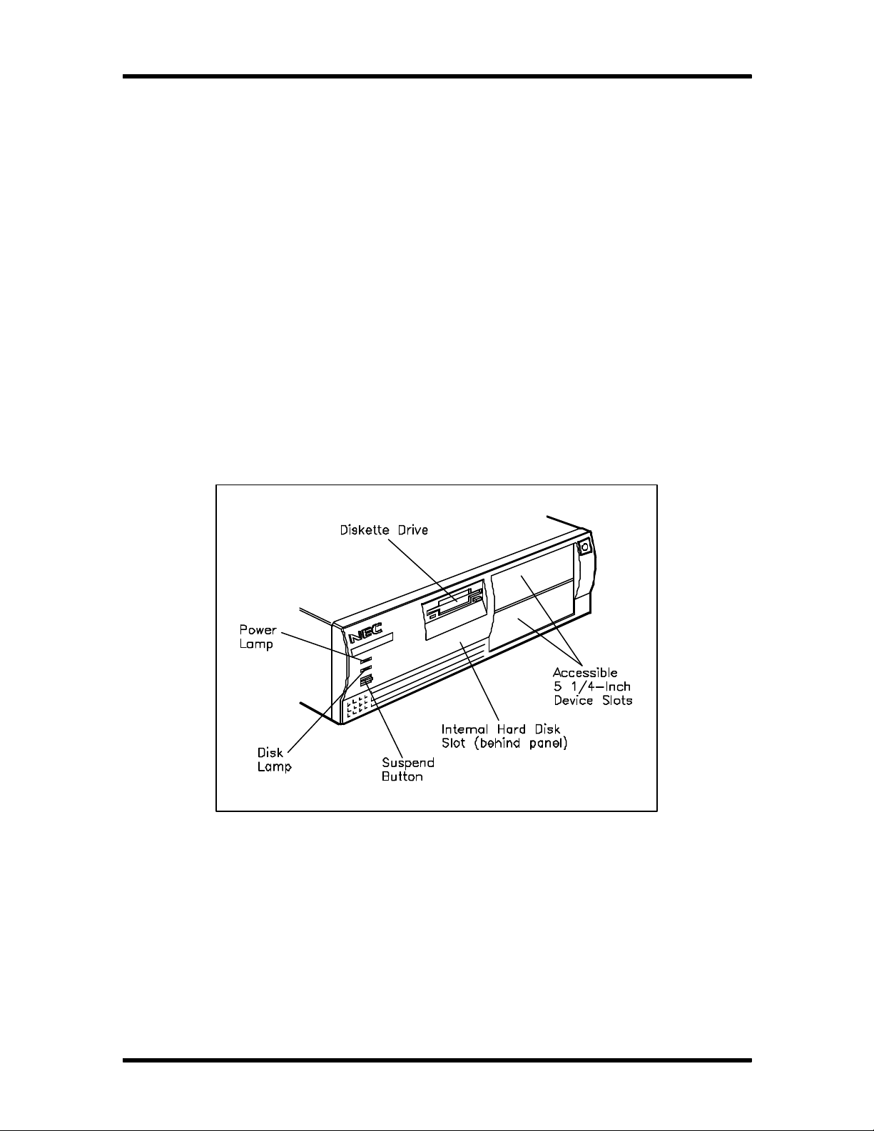
Figure Section 1-1 shows front panel features of a typical desktop system. Multimedia systems
come with a quad-speed CD-ROM reader installed in the upper accessible device slot.
Figure Section 1-1 Desktop System Controls and Storage Slots
Technical Information 1-3
MINITOWER SYSTEM UNIT
The minitower chassis provides an enclosure for the system board, power supply, five
storage device slots, a six-connector PCI/ISA backboard, and five expansion slots. The
expansion slots include three ISA slots, one dedicated PCI slot, and one shared PCI/ISA slot.
For network configurations, one slot has a network board installed and the four remaining slots
are empty. For multimedia configurations, one slot has a sound board installed and the four remaining slots are empty. All other configurations ship with the slots empty.
The storage device slots can accommodate a 3 1/2-inch diskette drive, two 3 1/2-inch hard
disks, and three accessible 5 1/4-inch storage devices (1.6-inch height). The non-multimedia hard
disk systems ship with a 3 1/2-inch diskette and a 3 1/2-inch hard disk drive, leaving three accessible 5 1/4-inch storage device slots available for optional devices. The multimedia systems ship
with a 3 1/2-inch diskette, a 3 1/2-inch hard disk drive, and a
5 1/4-inch CD-ROM reader, leaving two 5 1/4-inch storage device slots available for
optional devices.
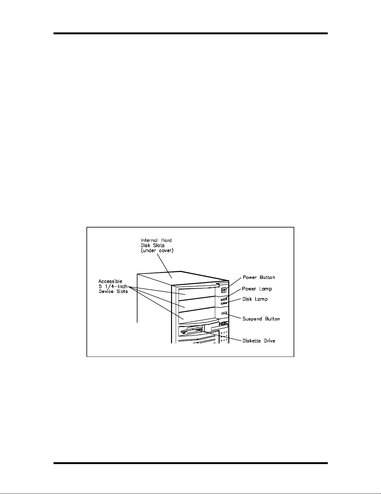
Figure Section 1-2 shows front panel features of a typical minitower system. Multimedia systems
come with a quad-speed CD-ROM reader installed in the lower accessible device slot.
Figure Section 1-2 Minitower System Controls and Storage Slots

1-4 Technical Information
System Board
The system board is identical for all configurations. The system board contains a Flash ROM
which is upgradeable through the BIOS Update utility (see Section 2).
Key features of the system board are as follows:
n Intel Pentium 75 MHz Pentium processor
n 16 kilobyte (KB) internal dual write-back cache integrated on the processor
n 256-KB write-back secondary cache memory
n PCI local bus for fast data transfer
n support for Intel processor upgrades
n 8 megabytes (MB) of random access memory (RAM) (16 MB in the multimedia con-
figurations)
accepts 32-bit or 36-bit, 70-nano second (ns) single-inline memory modules
(SIMMs)
expandable to 128 MB
n Peripheral Component Interconnect (PCI) graphics controller and 32-bit PCI bus
supports 640 x 480 resolution with up to 16.8 million colors, 800 x 600 with up to
16.8 million colors, 1024 x 768 with up to 64 K colors, and 1280 x 1024 with up
to 256 colors
1-MB (two 256K x 16) video dynamic RAM (DRAM), expandable to 2 MB
supports Display Data Channel (DDC) monitors.
n two intelligent drive electronics (IDE) interface connectors
one fast IDE/PCI connector (primary interface) used by the hard disk drive to
transfer data at the hard disk's opti mum rate
one standard IDE connector (secondary interface) used for the CD-ROM reader
n energy saving features: system switches to power save mode when idle for an
established amount of time
n 3 1/2-inch, 1.44-MB diskette drive

Technical Information 1-5
n PCI/ISA backboard configurations
desktop: three ISA expansion slots and one shared PCI/ISA slot
minitower: three ISA expansion slots, one dedicated PCI slot, and one shared
PCI/ISA slot
n external connectors providing an interface for the following external devices:
VGA-compatible monitor
personal system/2 (PS/2®)-style mouse
PS/2-style keyboard
Enhanced Parallel Port (ECP) and enhanced capabilities port (ECO) are supported
for a parallel printer
two buffered serial ports
multimedia MIDI/joystick, speakers, microphone, and headphone connectors on
the sound board (multimedia configurations only).
Table Section 1-1 lists the major chips on the system board. See Section 2, Setup and Operation, for a description of the system board's jumpers. See Appendix A, Connector Pin Assignments, for a list of the system board connectors.
Table Section 1-1 System Board Chips
Chip Description
P54C (CPGA) 75-MHz Intel Pentium processor
28F001 128k x 8 Flash ROM
Intel Mercury PCI/ISA Chip Set
8243LX
82433LX
82378ZB
Intel 82091AA Super I/O controller
Dallas DS12887 Real-time clock
Cirrus Logic CL-GD5430/34 PCI graphics controller
PCI cache and memory controller
Local bus extension
System I/O bridge

1-6 Technical Information
Processor
The PowerMate VP series of computers use the 75 MHz Pentium processor with an
internal speed of 75 MHz and an external speed of 50 MHz. The processor has 16 KB of writeback internal cache, 8 KB for instructions and 8 KB for data. A math coprocessor is integrated in
the processor.
The processor is an advanced 64-bit processor designed to optimize multitasking operating systems. The 64-bit registers and data paths support 64-bit addresses and data types.
To use the Pentium processor’s power, the system features an optimized 64-bit memory interface
and complementary 256-KB burst-mode secondary cache.
The processor cache design uses 15-ns static random access memory (SRAM) that allows data
to be sent or received from cache with one wait burst.
The processor is compatible with 8-, 16-, and 32-bit software written for the Intel386™, Intel486™, and Pentium processors.
To accommodate future technologies and work requirements, the Pentium processor comes in a
320-pin ZIF socket. The socket provides an upgrade path to the next generation processor.
Secondary Cache
The 16-KB primary cache is integrated in the processor. The system board contains 256 KB of
secondary cache, external to the processor. Cache memory improves read perform ance by holding copies of code and data that are frequently requested from the system memory by the processor. Cache memory is not considered part of the expansion memory.
The cache is connected directly to the processor address bus and uses physical addresses. A bus
feature known as burst enables fast cache fills. Memory areas (pages) can be designated as
cacheable or non-cacheable by software. The cache can also be enabled and disabled by software.
The write strategy of the cache (primary and secondary) is write-through. If the write is a cache
hit, an external bus cycle is generated and information is written to the cache. Any area of memory can be cached in the system. Non-cacheable portions of memory are defined by software.
The cache can be cleared by software instructions.
Flash ROM
Machine language programs are stored in a 28F010 Flash ROM known as the system's ROM
BIOS. The system BIOS and video BIOS are contained in the ROM. The Flash ROM is 128
KB. It consists of 64 KB of system BIOS and 32 KB of video BIOS.

Technical Information 1-7
The Flash ROM allows the BIOS to be upgraded with the BIOS Update utility without
removing the ROM (see Section 2, Setup and Configuration). The BIOS can only be reprogrammed by powering on the system with the BIOS Update utility diskette in Drive A.
The BIOS programs execute the Power-On Self-Test, initialize processor controllers, and interact with the display, diskette drives, hard disks, communication devices, and peripherals. The
sy stem BIOS also contains the Setup program and provides VGA controller support. The hardware setup default copies the ROM BIOS into RAM (shadowing) for maximum performance.
System BIOS is located in the upper portion of the Flash ROM and video BIOS in the lower
portion. System BIOS is located between F0000h-FFFFFh and supports shadowing and shadowed memory. System BIOS is write protected and automatically enabled.
Video BIOS is located between C0000h and C7FFFh. If the internal video is disabled, this range
is mapped to ISA. The system memory map in shown in Table Section 1-2.
Table Section 1-2 System Memory Map
Memory Space Size Function
000000-07FFFF 512 KB Conventional base memory
080000-09FBFF 128 KB Extended conventional base memory
09FC00-09FFFF 1 KB Extended BIOS Data
0A0000-0BFFFF 128 KB On-board video memory
0C0000-0C7FFF 32 KB On-board BIOS
0C8000-0E7FFF 128 KB Available high DOS memory (open to ISA and PCI bus)
0E8000-0ECFFF 20 KB Plug-n-Play ESCD data
0ED000-OEDFFF 4 KB Reserved for logo
0EE000-0EFFFF 8 MB Flash boot block (available for HIMEM)
0F0000-0FFFFF 64 KB System BIOS
1000000- On-Board 130 MB Extended and/or Expanded system memory
Flash ROM supports the reprogramming of the system and built-in video BIOS. A jumper on the
system board enables or disables the BIOS flashing feature. The factory default for the jumper is
enabled, allowing the BIOS to be flashed. See Section 2, Setup and Operation, for jumper information. If the BIOS upgrade is interrupted, see Section 4, Maintenance and Troubleshooting, for
information on recovering the BIOS if there is a catastrophic failure.

1-8 Technical Information
Power Management
Each system incorporates power management features that lower power consumption when there
is no activity detected from the keyboard, mouse, diskette drive, CD-ROM reader, or hard disk
drive after a pre-defined period of time. As soon as activity is detected the system resumes where
it left off.
When Power Management is enabled, the computer automatically activates power-saving features and enters a suspend mode whenever inactivity is sensed. The computer's power-saving
functions are as follows.
n Reduces the CPU clock speed
The CPU, cache, and video clock speeds are reduced, putting the computer in the
suspend mode.
n Blanks out the monitor
Puts the video controller into suspend mode. The vertical sync clock and blank signals
to the monitor are disabled.
n Forces the IDE devices into stand-by mode
n A suspend command is sent to the IDE devices which put the devices into a stand-by
mode.
I/O Addressing
The processor communicates with I/O devices by I/O mapping. The hexadecimal (hex)
addresses of I/O devices are listed in Table Section 1-3.
Table Section 1-3 I/O Address Map
Address (Hex) I/O Device Name
0000-000F DMA controller 1 (channel 0-3)
0200-0021 Interrupt controller 1
0400-0043 Timer 1
0408-004B Timer 2
0060 Keyboard controller byte
0061 NMI, speaker controller byte
0070, bit 7 Enable NMI
0070, bit 6:0 Real-time clock address
0071 Real-time clock data

Technical Information 1-9
Table Section 1-3 I/O Address Map
Address (Hex) I/O Device Name
0073 Reserved for system board configuration
0075 Reserved for system board configuration (read only)
0078 BIOS timer
0080-008F DMA page master
00A0-00A1 Interrupt controller 2
00C0-00DE DMA controller 2 (channel 4-7)
00F0 Reset numeric error
0170-0177 Secondary IDE channel
01F0-01F7 Primary IDE channel
0278-027B Parallel port 2
02F8-02FF Asynchronous communications port 2
0376 Secondary IDE channel command port
0377 Secondary IDE channel status port
0378-037F Parallel port 1
03BC-03BF Parallel port 2
03C0-03CF Video Graphics Array (VGA) compare registers
03E8-03EF Serial port 3
03FO-03F5 Diskette channel 1
03F6 Primary IDE channel command port
03F7 (write) Diskette channel command port
03F7, bit 7 Diskette change channel 1
03F7, bits 6:0 Primary IDE channel status port
03F8-03FF Asynchronous communications port 1
0CF8 PCI Configuration Space Enable
0CF9 Deturbo Mode Enable
C000-C0FF 8243LX configuration registers
C200-C2FF 823781B configuration registers
C300-C3FF Cirrus Video configuration registers

1-10 Technical Information
System Memory
The system comes standard with 8 MB of memory (16 MB in multimedia configurations),
640 KB of base memory and 7 MB of extended memory. System memory can be expanded up
to 128 MB, using optional single in-line memory modules (SIMMs) installed in SIMM sockets.
Four SIMM sockets are integrated on the system board. Non-multimedia systems ship with two
4-MB SIMMs installed in two sockets. Multimedia configurations ship with two 8-MB SIMMs
installed in two sockets.
The SIMM memory sockets accept 4-, 8-, 16-, 32-, or 64-MB SIMMs, either 32-bit (no parity) or 36-bit (parity). The factory installed high-speed RAM is 32 bits wide. SIMMs are 1 MB x
32 bit (4 MB), 2 MB x 32 bit (8 MB), 4 MB x 32 bit (16 MB), 8 MB x 32 bit (32 MB), and 16
MB x 32 bit (64 MB). When the standard SIMM(s) is removed, four 32-MB SIMMs may be
i nstalled for a total of 128 MB.
CAUTION: SIMMs must match the tin metal plating used on the system board SIMM sockets. When
adding SIMMs, use tin-plated SIMMs.
SIMMs install directly on the system board. Different size SIMMs may be intermixed.
Each SIMM is inserted into a socket or bank. The system board's four SIMM sockets are assigned as banks 0 through 3. For non-multimedia configurations, the standard 8 MB of memory is
installed in bank 0. The multimedia configurations have two 4 MB SIMMs installed in banks 0
and 1. See Section 3, Options, for installation instructions and SIMM memory configurations.
Interrupt Controller
The interrupt controller operates as an interrupt manager for the entire AT system envi ronment.
The controller accepts requests from peripherals, issues interrupt requests to the processor, resolves interrupt priorities, and provides vectors for the processor to determine which interrupt
routine to execute. The interrupt controller has priority assignment modes that can be reconfigured
at any time during system operations.
The interrupt levels are described in Table Section 1-4. Interrupt-level assignments 0 through 15
are in order of decreasing priority. See Section 2, Setup and Operation , for information on
chan ging the interrupts using Setup.
Table Section 1-4 Interrupt Level Assignments
Interrupt Priority Interrupt Device
IRQ00 Counter/Timer
IRQ01 Keyboard

Technical Information 1-11
Table Section 1-4 Interrupt Level Assignments
Interrupt Priority Interrupt Device
IRQ02 Cascade (INT output from slave)
IRQ03 COM2*
IRQ04 COM1*
IRQ05 Parallel Port 2
IRQ06 Diskette Drive Controller*
IRQ07 Parallel Port 1*
IRQ08 Real-time clock
IRQ09 Available
IRQ10 Available
IRQ11 Available
IRQ12 PS/2 mouse*
IRQ13 Coprocessor
IRQ14 Primary IDE
IRQ15 Secondary IDE
*Industry standard locations
Video Controller
The Circus Logic CLDG5434 PCI graphics controller combines powerful elements aimed at addressing the requirements of personal computer designs. State of the art techniques have been
added for optimizing performance in computer graphic intensive applications and graphical user
interfaces (GUI). A variety of industry standard 32-bit local bus interfaces are integrated on chip.
The key is that local bus interfaces are 32-bit wide.
Included in the video controller are cost saving features such as an integrated palette DAC and
clock synthesizer along with integrated support for multiple bus interfaces and flexible DRAMbased display memory configurations.
The TrueColor RAMDAC provides 24-bit true color. The integrated dual clock synthesizer allows full programmability of MCLK (memory clock) and PCLK (pixel clock). The integrated
clock synthesizer supports frequencies from 390 kHz to 120 MHz. The CLDG5434 supports up
to 2 MB of display memory. The video memory is 256K x 16 DRAM.

1-12 Technical Information
The VESA display power management signaling (DPMS) standard is supported, enabling standby, suspend, and off power saving modes. This includes the ability to independently stop
HSYNC or VSYNC and hold them at a static level. Additionally the RAMDAC may be powered-down and the clock frequencies lowered for further power savings. Color Key and video
overlay are supported for optional multimedia applications.
Video Memory
The 1 MB of on-board video DRAM is expandable to 2 MB and provides 640 x 480
resolutions with up to 16.8 million colors, 800 x 600 with up to 16.8 million colors,
1024 x 768 with up to 64 K colors, and 1280 x 1024 with up to 256 colors. Table Section 1-5
lists the resolutions available with the installed video memory.
Table Section 1-5 Video Resolutions and Frequencies
Resolution
640 x 480 1 MB 256 60 31.5
640 x 480 1 MB 256 72 37.0
640 x 480 1 MB 256 72 44.6
640 x 480 1 MB 65K 60 31.5
640 x 480 1 MB 65K 72 37.0
640 x 480 1 MB 65K 72 44.6
640 x 480 1 MB 16.7M 60 31.5
640 x 480 1 MB 16.7M 72 37.0
640 x 480 1 MB 16.7M 72 44.6
800 x 600 1 MB 256 95(i) 33.8
800 x 600 1 MB 256 56 35.2
800 x 600 1 MB 256 60 37.9
800 x 600 1 MB 256 70 44.5
800 x 600 1 MB 256 72 48.0
Memory
Required
Color
Video Clock (Hz) Horiz Sync (KHz)
800 x 600 1 MB 256 76 52.4

Technical Information 1-13
Table Section 1-5 Video Resolutions and Frequencies
Resolution
800 x 600 1 MB 65K 95(i) 33.8
800 x 600 1 MB 65K 56 35.2
800 x 600 1 MB 65K 70 44.5
800 x 600 1 MB 65K 72 48.0
800 x 600 2 MB 65K 76 52.4
800 x 600 2 MB 16.7M 95(i) 33.8
800 x 600 2 MB 16.7M 56 35.2
800 x 600 2 MB 16.7M 60 37.9
800 x 600 2 MB 16.7M 70 44.5
800 x 600 2 MB 16.7M 72 48.0
1024 x 768 1 MB 256 87(i) 35.5
1024 x 768 1 MB 256 60 48.4
1024 x 768 1 MB 256 66 53.9
1024 x 768 1 MB 256 70 56.1
Memory
Required
Color
Video Clock (Hz) Horiz Sync (KHz)
1024 x 768 1 MB 256 72 57.9
1024 x 768 1 MB 256 76 61.4
1024 x 768 2 MB 65K 87(i) 35.5
1024 x 768 2 MB 65K 60 48.4
1024 x 768 2 MB 65K 66 53.9
1024 x 768 2 MB 65K 70 56.1
1024 x 768 2 MB 65K 72 57.9
1024 x 768 2 MB 65K 76 61.4
1280 x 1024 1 MB 16 87(i) 50
1280 x 1024 1 MB 16 95(i) 50
1280 x 1024 2 MB 256 87(i) 50
1280 x 1024 2 MB 256 95(i) 50
1280 x 1024 2 MB 256 60 64.0
1280 x 1024 2 MB 256 70 74.6
1280 x 1024 2 MB 256 74 81.1
(I) Interlaced.

1-14 Technical Information
IDE/PCI-Bus Backboard
The desktop IDE/PCI-bus backboard provides three ISA expansion slots and one shared
IDE/PCI expansion slot. The backboard is plugged into the bus connector on the desktop system
board. The minitower PCI/IDE bus backboard provides three ISA expansion slots, one dedicated PCI expansion slot, and one shared IDE/PCI expansion slot. The backboard is plugged
into the bus connector on the minitower system board.
ISA Bus
The system board uses the ISA bus for transferring data between the processor and I/O peripherals and expansion boards. The ISA bus supports 16-bit data transfers and typically operates at
8 MHz. ISA expansion slot connector pin assignments are provided in
Appendix A.
PCI Local Bus
The industry-standard PCI-bus is a highly-i ntegrated I/O interface that offers the highest performance local bus available for the Pentium processor. The PCI-bus supports burst modes that send
large chunks of data across the bus, allowing fast displays of high-resolution im ages.
The high-bandwidth PCI-bus eliminates the data bottleneck found in traditional systems, maintains
maximum performance at high clock speeds, and provides a clear upgrade path to future
technologies. PCI expansion slot connector pin assignments are provided in Appendix A.
PCI Auto Configuration
The system comes with a PCI auto configuration utility that operates in conjunction with the system’s Setup utility. The utilities automatically configure interrupts, DMA channels, I/O space, and
other parameters to allow addition of PCI boards with minimal intervention.

Technical Information 1-15
Parallel Interface
The system has a 25-pin parallel port on the system board. Specifications for this port conform to
the IBM-PC standards.
The BIOS has automatic ISA printer port sensing. If the BIOS detects an ISA printer port
mapped to the same address, the built-in printer port is disabled. The BIOS also sets the first
parallel interface port it finds as LPT1 and the second port it finds as LPT2. The interrupt is selected to either IRQ5 or IRQ7 via the Setup and jumper settings.
Interrupt levels for the parallel port are given in Table Section 1-6. Software selectable base
addresses are 3BCh, 378h, and 278h.
Parallel interface signals are output through the system board's 25-pin, D-subconnector. The connector is located at the rear of the system unit. Pin locations for the parallel interface connector
are shown in Appendix A.
NOTE: Any interrupts used for the built-in
parallel port are not available for ISA parallel ports.
Table Section 1-6 Parallel Port Addressing and Interrupts
Starting I/O Address Interrupt Level Port
378 IRQ05 LPT1
278 IRQ05 LPT1 or LPT2
3BC IRQ05 LPT1 or LPT2
378* IRQ07 LPT1
278 IRQ07 LPT1 or LPT2
3BC IRQ07 LPT1 or LPT2
*Default for parallel port
Serial Interface
The system has two standard serial ports (COM1 and COM2). The serial ports support the
standard RS-232C interface (16550 compatible). I/O addresses and interrupt levels for the two
channels are given in Table Section 1-7. The interrupt is selectable via Setup to either IRQ3 or
IRQ4. Software selectable base addresses are 3F8h, 2F8h, 3E8h, and 2E8h. Serial interface signals are output through the system board's 9-pin, D-subconnector. The connectors are located at
the rear of the system unit. Pin locations for the serial interface connector are shown in Appendix
A.

1-16 Technical Information
NOTE: Any interrupts used for the built-in serial
ports are not available for ISA parallel ports.
Table Section 1-7 Serial Port Addressing and Interrupts
Starting I/O Address Interrupt Level Port
3F8* IRQ04 COM1
2F8* IRQ03 COM2
3E8 IRQ04 COM3
2E8 IRQ03 COM4
*Default for serial port
Serial interface specifications include:
n Baud rate up to 19.2 KB per second
n Word length - 5, 6, 7, or 8 bits
n Stop bit - 1, 1.5, or 2 bits
n Start bit - 1 bit
n Parity bit - 1 bit (odd parity or even parity).
Indicator Panel
The indicator panel is attached to the front panel and contains the power lamp, hard disk drive
busy lamp, and suspend button. The indicator panel electrically attaches to the system board
through connector J11 (suspend connector), J14 (hard disk drive busy lamp
connector), and J16 (power lamp connector).
POWER SUPPLY
The power supply is mounted inside the system unit. It supplies power to the system board, option boards, diskette drives, hard disks, keyboard, and mouse. The power supply is connected to
the system board through connector J6. A fan inside the power supply provides proper ventilation
for the system. The power supply in the desktop supplies 145W of power. The minitower power
supply provides 200W. Power requirements and specifications for both power supplies are provided in Appendix C.

Technical Information 1-17
DISKETTE DRIVE
Up to two diskette drives are supported in the system. The installed drive is connected by a single
ribbon cable with one drive connector. An optional cable with two drive connectors allows the
connection of two drives. The system refers to the diskette drives as A and B. Drive A is for the
first drive, B is for a second optional diskette drive. The diskette drive cable plugs directly into the
system board (connector J5). Typically both diskette drives are terminated. See Section 3, Options, for installing an optional 5 1/4-inch diskette drive.
Specifications for the diskette drives are provided in Appendix B, Specifications.
HARD DISK DRIVE
The system provides IDE/PCI interface connectors on the system board. The system board supports up to two IDE devices on the primary connector and two IDE devices on the
secondary connector. The system unit provides one storage slot for a 3 1/2-inch hard disk (1inch height), and one available storage slot for an optional 5 1/4-inch device (1.6-inch height).
See Section 3, Options, for installing an optional hard disk drive.
Specifications for the diskette drives are provided in Appendix B, Specifications.
NETWORK BOARD
Some systems are configured with a network board. The network board provides three jacks for
connecting the system to the local network. The network board is a 3COM, 16-bit, Etherlink™
network interface board. Features are as follows:
n Hardware Plug and Play is supported
n Hardware configuration is software selectable (no jumpers or switches to set)
n AutoLink™ auto installation software which installs all Novell
client software into the operating system.
n Auto select media type capability, which enables certain drivers to automatically detect
the type of media connector that connects the network board to the network
n Network management support through Transcend ™ Etherlink SmartAgent™ soft-
ware, which is auto-installed with the drivers.
The network interface board has connectors for thin, thick, or twisted-pair Ethernet connections.
A network user’s guide and drivers are shipped with network configured systems.
®
Netware® DOS ODI

1-18 Technical Information
MULTIMEDIA COMPONENTS
Systems configured for multimedia come with a quad-speed CD-ROM reader, sound board, a
pair of speakers, and microphone. The following subsections briefly describe each. Information
on attaching the speakers and microphone is in Section 2, Setup and Operation.
Quad-Speed CD-ROM
The IDE quad-speed CD-ROM reader is pre-installed as drive E on multimedia configurations.
Operation of the reader is described in Section 2, Setup and Configuration. The CD-ROM
reader can be used to load programs from a CD or it can be used to play audio CDs. The CDROM reader is connected to the secondary IDE/PCI port on the system board.
Sound Board
The sound board is a Creative Labs Sound Blaster™ Audio Card. The sound board is installed
in the ISA/PCI backboard. System settings for the sound board can be found in a sound board
directory on the computer's hard disk drive. For information on changing the sound board settings, see Appendix D in this manual and the Creative Labs Multimedia Audio Card User's
Guide that comes with the computer.
The sound board uses 16-bit DMA data transfer and has software addressable IRQs and DMAs
for versatility. External connectors accept speakers or headphones, a microphone, stereo input,
and a musical instrument digital interface (MIDI) or joystick attachment. The speaker jack offers
a four-watt (RMS)/channel amplifier. The joystick port allows a full
duplex MIDI.
The advanced frequency modulation (FM) stereo synthesizers use a 16-bit digital-to-analog converter (DAC) with four operator FM sounds and twenty stereo voices. The sound board provides digital sampling up to 44 kHz and playback with dynamic filtering from 2 to 44 kHz. The
sound board is fully compatible with the ADLib™ software library.
Connectors for the board are shown in Section 2, Setup and Operation. See Appendix A for
connector pin assignments.
Speakers
The multimedia systems come with a pair of high-quality speakers, AC adapter, and connecting
wires. The speaker set features a volume control, treble boost, bass boost, and a power-on button. The speakers connect to the speaker jacks on the back of the system unit. Speaker features
are as follows.
n 3-inch magnetically shielded full-range speakers for monitor, drive, and disc protection
n Bass (DXBB) boost switch

Technical Information 1-19
n Treble boost switch
n Built-in power booster
n Power source: 6 volt (V) AC power adapter or four “C” batteries (not included)
n Speaker impedance: 8 ohms
n Power output: 3.6 watts
n Frequency response: 60 – 15000 Hz
n 3.5 mm stereo plug
Microphone
The microphone that comes with the multimedia systems record voice and sound into com puter
data files. The microphone jack is located on the back of the system.
KEYBOARD
The PS/2-style keyboard is standard equipment for the system. The keyboard provides a numeric
keypad, separate cursor control keys, and 12 function keys, capable of up to 48 functions. Status
lamps on the keyboard indicate: Num (Numeric) Lock, Caps (Capital) Lock, and Scroll Lock
key status. The keyboard's six-pin connector is plugged into the rear of the base unit. The PS/2style keyboard connector pin assignments are given in Appendix A, Connector Pin Assignments.
MOUSE
A PS/2-compatible mouse is standard equipment for the system. The mouse has a self-cleaning
mechanism that prevents a buildup of dust or lint around the mouse ball and tracking mechanism.
Periodically the mouse ball must be cleaned. See Section 4, Maintenance and Troubleshooting,
for information on cleaning the mouse.
POWER MANAGEMENT
Each computer system is Energy Star compliant and incorporates power management
features that lowers power consumption when there is no activity detected from the keyboard,
mouse, diskette drive, or hard disk drive after a predefined period of time. As soon as activity is
detected, the system resumes where it left off. To enable Power Management, see Section 2,
Setup.
If the computer is put into suspend mode by pressing the suspend button, the suspend
button must be pressed again to exit the suspend mode. System activity will not resume from suspend mode.

1-20 Technical Information
When Power Management is enabled, the computer automatically activates power-saving features and enters a suspend mode whenever inactivity is sensed. The computer's power-saving
functions shuts down all installed devices, video signals to the monitor, and processor.
PLUG AND PLAY
The system comes with Plug and Play system support installed, and requires only the Plug and
Play operating system. When the Plug and Play operating system is installed, the system will
automatically configure newly added Plug and Play boards.
Plug and Play boards are ISA boards with the new configuration capability. Most currently available ISA boards do not have the new capability. However, Plug and Play boards can be added
to the system.
To work in a system, boards often use a variety of dedicated resources. If two boards try to use
the same resource, one board might not work or the system might not function in the way you expect.
NOTE: Generally, a resource can be used by only
one board or device. However, some boards can
share the same DMA or IRQ resources. The board
manufacturer's documentation tells you whether a
board supports shared resources.
If an ISA board does not support shared resources and a Plug and Play board is not aware that
the ISA board is using the same resource it has selected, an ISA Configuration Utility (ICU) is
need. The ICU is used to eliminate the guess work from the configuration procedure. Although
most Plug and Play boards come with an ICU, an ICU can be obtained from the NEC Bulletin
Board Service (see Section 4, Troubleshooting and Maintenance).
Plug and Play boards are dynamic in nature — the system allocates resources to these boards
upon system boot. Some device drivers support this dynamic board configuration, but some do
not.
Device drivers that do not support the dynamic board configuration are also known as static
device drivers. If you are using a static device driver, you need to permanently associate
resources with a Plug and Play board, instead of relying on the default Plug and Play behavior.
Otherwise, the device driver might not be able to find the board the next time the system boots.
DESKTOP MANAGEMENT INTERFACE
The Desktop Management Interface (DMI) is a new standard for managing computer systems.
DMI is an interface between management applications and managed components such as systems, network boards, and printers used with or without networked computers.

Technical Information 1-21
DMI allows a computer running a network management application to retrieve system tracking information such as memory capacity, disk capacity, expansion board settings, or applications. It is
easy to get the status of each system via DMI even if the network consists of computers from different manufacturers. DMI also supplies Plug and Play capabil ity. DMI is not a protocol but an
i nterface. It complements network protocols like the Simple Network Management Protocol
(SNMP).
The DMI provides support for attributes such as system serial number, product model num ber,
and BIOS revision number.
DMI Components
The DMI consists of two major functional components, the Component Interface (CI) module
and the Windows Management Information Format (MIF) Browser. The CI module provides the
instrumentation and interface between the BIOS, NEC Services, and the DMI Service Layer.
The MIF Browser displays and manages existing attributes in the MIF database.
Manageable Products
Manageable products are hardware, software, or peripherals that occupy or are attached to a
desktop computer or network server. These can be hard disks, word processors, CD-ROMs,
printers, operating systems, graphics boards, modems, etc. Manageable products or components
can come with the system or be added later. Each component supplies information to the MIF
database by means of a MIF file that contains the product’s pertinent management information.
CI Module
The CI module is a Windows Direct Interface application provided by NEC Technologies. The
module uses the CI to communicate with the SL and provides management for a set of components defined in the PC system group standard MIF. The NEC implementation of this MIF provides management for a variety of attributes. Windows starts the CI module which must be
running in the background. The module is added to the Windows StartUp program group during
DMI setup.
MIF Browser
The MIF Browser is a Windows application provided by NEC Technologies. The Browser uses
the MI to provide access to MIF attributes and their respective values and to provide the ability
to set attributes and manage DMI components.
The Browser is a local application; it only accesses the local MIF database. The Browser lets you
access MIF attributes according to the structure defined by the DMTF. It is not intended to be a
general PC management application. If a more comprehensive management application is desired,
use a product such as Intel’s LanDesk Manager.

1-22 Technical Information
The MIF Browser has a graphical user interface. It displays components in a hierarchical tree
structure. Use it to install or remove MIF files to and from the database.
NOTE: The user is not expected to install or remove MIF com ponents.
By pointing and clicking, components can be expanded and collapsed. To obtain specific
attributes, simply double click on an attribute and retrieve the associated value.
The toolbar can also be used to manipulate or obtain information on the MIF file.
The buttons are defined as follows (starting at the left):
n Install — to install a new MIF file. Use to add a component, such as a printer that
supports DMI, to the MIF database.
n Remove — to remove a MIF file. Use to remove a component from the MIF
database. Only remove the system component when it needs to be replaced.
n Expand — to expand a component.
n Collapse — to collapse a component.
n View Component Detail —to review the selected component's details.
n View Group Detail — to review the selected group’s details.
n View Attribute Detail — to review the selected attribute’s details.
Upon exiting the Browser, the program saves the current viewing configuration. The next time you
use the Browser, it restores all the viewing screens to the last known position.
Usage
To start the Browser, double click on the MIF Browser icon in the NEC DMI Interface group.
The Browser is easy to use. For example, to obtain the serial number, first position the cursor
over the NEC system component and double click to expand it. Position the cursor over the
Component ID group and double click to expand it. Position the cursor over the Serial Number
attribute and click once; the serial number is given in the value field.
Troubleshooting
If trouble is experienced in using the MIF Browser, here are a few suggestions on how to clear up
the problem.
If the product name, serial number, system boot time, or other NEC attribute returns a not available value, check the following:

Technical Information 1-23
n Look at the autoexec.bat file to see if the line DIR%\WIN16\BIN\NECDMI.EXE is
present.
n Make sure the file NECDMI.DAT is located in the \WIN16\BIN subdirectory.
n Check that NECCI.EXE is running.

Section 2
Setup and Operation
This section provides information on hardware setup for the PowerMate VP series
computers. Setup includes unpacking, cabling, and powering up the system. It also includes configuring the system with the system setup programs. Section 3 provides information for installing
options.
UNPACKING AND REPACKING
Find an area away from devices that generate magnetic fields (electric motors, transform ers, etc.).
Place the carton on a sturdy surface, and carefully unpack the system. The carton contents for
non -multimedia configurations include the system unit, keyboard, mouse, power cord, user
documentation, and system recovery diskette. The carton contents for multimedia configurations
include the system unit with a quad-speed CD-ROM player, keyboard, mouse, speakers, power
cord, user documentation, CD-ROM disc with hotload backup, and system recovery diskette.
Repack the system using the original shipping carton and packing material. Part numbers for replacement shipping cartons and packing material are included in Section 5 and Section 6.
SETUP
Connect the system components according to the following two subsections.
n Desktop Configuration – for setting up desktop system units.
n Minitower Configuration – for setting up minitower system units.

2-2 Setup and Operation
Desktop Setup
Set up the desktop systems by making the following connections. (See the following subsection,
Minitower Setup, if setting up a minitower system).
1. At the rear of the system, set the voltage selector switch to 115V or 230V and plug the
power cord into the system power socket (see Figure Section 2-1).
CAUTION: The correct AC input voltage must be
properly set. Select the appropriate voltage with the
voltage selector switch located at the rear of the system.
Figure Section 2-1 Desktop Voltage Selector Switch

Setup and Operation 2-3
2. Connect the keyboard and mouse cables to the back of the system unit (see
Figure Section 2-2).
3. Connect the monitor and any other peripheral cables to the rear panel (see
Figure Section 2-2).
Figure Section 2-2 Desktop Peripherals Connections

2-4 Setup and Operation
4. Connect the network cables (network configurations only) to the rear panel (see Figure
Section 2-3).
Figure Section 2-3 Desktop Network Board Connections

Setup and Operation 2-5
5. If installing a multimedia system, connect multimedia components to the sound board as
shown in Figure Section 2-4.
Figure Section 2-4 Desktop Multimedia Connections

2-6 Setup and Operation
6. Press the power button to power-on the system. The power lamp lights.
7. Press the suspend button (see Figure Section 2-5) to place the unit in the power man-
agement mode.
Figure Section 2-5 Desktop Power Button, Lamps, and Suspend Button
The system has a built-in checking program that automatically tests the components at power-on.
One beep indicates that the system has successfully completed its power-on test.
If there is a problem, a series of beeps may occur. If this happens repeatedly after powering on
the system, power off the system and see Section 4 for troubleshooting.
NOTE: If the system displays a message
indicating that system settings have changed, run
Setup (see “System Configuration” later in this section).
If a problem occurs, and is not indicated by beeps, check the following items, then turn to Section
4 for troubleshooting. Check that:
n the power switch for the system unit and monitor are on.
n all cables and power cords are tightly connected.
n the electrical outlet is working.
n the monitor’s brightness and contrast are adjusted properly.

Setup and Operation 2-7
n all options are properly installed (see Section 3 for option installation).
Minitower Setup
Set up the minitower systems by making the following connections. (See the preceding subsection, Desktop Setup, if setting up a desktop computer.)
1. At the rear of the system, set the voltage selector switch to 115V or 230V and plug the
power cord into the power socket (see Figure Section 2-6).
CAUTION: The correct AC input voltage must be
properly set. Select the appropriate voltage with the
voltage selector switch located at the rear of the system.
Figure Section 2-6 Minitower Voltage Selector Switch

2-8 Setup and Operation
2. Connect the keyboard and mouse cables to the back of the system unit (see
Figure Section 2-7).
3. Connect the monitor and any other peripheral cables to the rear panel (see
Figure Section 2-7).
Figure Section 2-7 Minitower Peripherals Connections

Setup and Operation 2-9
4. Connect the network cables (network configurations only) to the rear panel (see Figure
Section 2-9).
Figure Section 2-8 Minitower Network Board Connections

2-10 Setup and Operation
5. If installing a multimedia system, connect mulitmedia components to the sound board
(Figure Section 2-9).
Figure Section 2-9 Minitower Sound/Fax/Modem Board Connectors

Setup and Operation 2-11
6. Press the power button to power-on the system (see Figure Section 2-10). The power
lamp lights.
7. Press the suspend button to place the unit in the power management mode.
Figure Section 2-10 Minitower Power Button, Indicators, and Suspend Button
The system has a built-in checking program that automatically tests the components at power-on.
One beep indicates that the system has successfully completed its power-on test.
If there is a problem, a series of beeps may occur. If this happens repeatedly after powering on
the system, power off the system and see Section 4 for troubleshooting.
NOTE: If the system displays a message indicating
that system settings have changed, run Setup (see
“System Configuration” later in this section).
If a problem occurs, and is not indicated by beeps, check the following items, then turn to Section
4 for troubleshooting. Check that:
n the power switch for the system unit and monitor are on.
n all cables and power cords are tightly connected.
n the electrical outlet is working.
n the monitor’s brightness and contrast are adjusted properly.
n all options are properly installed (see Section 3 for option installation).

2-12 Setup and Operation
CD-ROM READER
A quad-speed CD-ROM reader (see Figure Section 2-11) comes pre-installed as drive E in the
multimedia configurations. The reader is set as a master device, and is connected to the
secondary IDE/PCI port on the system board.
Use the CD-ROM reader to load and start programs from a CD. The CD-ROM reader can also
be used to play audio Cds. The CD-ROM reader has the following controls and indicators:
n jack for connecting headphones with a stereo mini-jack plug
n volume control for adjusting the headphone volume
n busy lamp that lights during read operations
n eject/reject button for opening or closing the CD tray when the power is on
n CD tray that opens and closes when the eject/retract button is pressed
n emergency eject hole in the front panel for manually opening the CD tray if power is
lost. Insert a jewelers screwdriver into the hole. Turn the screw counterclockwise to
open the tray and clockwise to close the tray.
Figure Section 2-11 CD-ROM Reader Controls and Indicators
To load a disc in the quad-speed CD-ROM reader, follow these steps.
1. Press the stop/eject button. The CD tray opens.
2. Put the CD, printed side up, into the tray.
3. Press the stop/eject button. The tray closes.
4. To remove the disc, press the stop/eject button. The tray opens, allowing removal of
the disc.

Setup and Operation 2-13
EXTERNAL MULTIMEDIA CONNECTIONS
This subsection explains how to connect multimedia components to the system’s multimedia connectors (multimedia configurations only). The connectors are located on the sound board at the
rear of the system and on the CD-ROM reader at the front of the system.
The sound board has a 15-pin connector and three jacks that attach multimedia components to
the back of the system.
The external connectors for the sound board are on the rear of the system unit. Figure Section 24 shows the desktop sound board connectors. Figure Section 2-9 shows the minitower connectors. Each connector is briefly described below.
n A line in jack allows connecting such devices as a cassette, DAT, or Minidisc player
for playback or recording.
n A microphone in jack allows connecting a microphone for voice input.
n A line out jack allows bypassing of the sound board’s internal amplifier so that the
speakers included with the system, powered speakers, or an external amplifier can be
connected.
n A speaker jack allows connection of unamplified speakers for audio output from the
sound board’s built-in power amplifier. Maximum output power is four watts per channel from four-ohm speakers and two watts per channel from eight-ohm speakers.
n A MIDI/Joystick connector allows connection of a MIDI synthesizer kit or a joystick
with a 15-pin D-subconnector.
Connecting the Speakers
The speakers operate once they are connected to the sound board. To use the built-in am plifier
for treble and bass control and additional volume, install the AC adapter. Connect the speakers
to the system unit as follows.
1. Open the covers at the rear of the speakers. Pull out the speaker cables.
CAUTION: Do not install batteries in the speakers
if using the AC adapter.

2-14 Setup and Operation
2. Connect the left speaker cable (with the dual plug) to the right speaker connector la-
beled TO LEFT SPEAKER (see Figure Section 2-12).
3. Connect the right speaker cable (with the single plug) to the SPK OUT jack on the
sound board at the rear of the system unit.
Figure Section 2-12 Ready 9520 Speaker Connections
Connect the 6-volt AC adapter as follows.
1. Remove any installed batteries from the speakers.
2. Plug the AC adapter into the DC 6V jack on the back of the left speaker (see Figure
Section 2-12).
3. Plug the other end of the AC adapter into a properly grounded wall outlet.

Setup and Operation 2-15
SYSTEM CONFIGURATION
This section describes the Setup utility program that allows the system configuration information to
be viewed and changed.
NOTE: The system ships from the factory with the
correct system parameters for the configuration.
Unless setting the time and date, customizing the
sy stem, or adding optional hardware, Setup does
not need to be run.
System configuration information is stored in nonvolatile memory. Nonvolatile memory in the system is a complementary metal-oxide semiconductor (CMOS) chip backed by a
real time clock (RTC)/battery module on the system board. The module supplies continuous
power to the CMOS memory and maintains configuration information when system power is off.
The Setup utility is used to view and set system parameters. Use the Setup utility to:
n set the time and date.
n update or check system parameters when adding or removing expansion options.
n change or set power management features.
n correct a hardware discrepancy when the Power-On-Self-Test (POST) displays an er-
ror message and a prompt appears to run Setup.
n check the installation of optional memory by comparing the amount of memory installed
with the amount of memory displayed by Setup.
n change certain system operating parameters, such as boot device sequence or key-
board parameters.
n configure system connections for peripherals such as the diskette drive, hard drives,
and devices connected to the printer and serial ports.
n customize the system with security features such as passwords, diskette drive restri c-
tion, virus check reminder, and system backup reminder.
n set system parameters if the system board requires replacing.

2-16 Setup and Operation
How to Start Setup
To start the Setup utility, follow these steps:
1. Turn on or reboot the system. Setup displays the following message:
Press <F2> to enter SETUP
2. Press F2. Setup’s Main Menu window appears similar to the following screen.
NOTE: The screen shown is typical of the system.
The actual items on the Main Menu depend upon
the hardware installed in the system.
System Time: [10 :19:20] Item Specific Help
System Date: [03/12/1995]
Diskette A: [1.44 MB, 3 ½"] <Tab>, <Shift-Tab>, or
Diskette B: [Not Installed] <Enter> selects field.
> IDE Adapter 0 Master: C: 540 Mb
> IDE Adapter 0 Slave: None
> IDE Adapter 1 Master: None
> IDE Adapter 1 Slave: None
Video System: [EGA/VGA]
> Memory Shadow: [Enabled]
> Boot sequence: [A: then C:]
> Numlock: [Auto]
System Memory: 640 KB
Extended Memory: 7 MB
PhoenixBIOS Setup — Copyright 1992-95 Phoenix Technologies Ltd.
Main Advanced Security Power Exit
How to Use Setup
The Setup utility has a Main Menu window and five top-level menus with submenus. The Main
Menu window contains the following areas:
n A title line — the top line of the Main Menu. This line displays the Setup utility name
and copyright message.
n The menu bar — the line under the Setup title line. The menu bar contains five top-level
menus for setting system parameters.
n A Main Menu summary window — the center area on the left side of the screen. This
area provides a summary of Main Menu Setup parameters. Main Menu parameters
can be set directly from this window or from the Main menu option in the legend bar.

Setup and Operation 2-17
n The Field Help window or Item Specific Help — the area on the right side of the
screen. This help area provides help information for the Setup option currently selected.
n The legend bar — the area at the bottom of the screen. The legend bar provides a
summary of command keys for using Setup.
n The General Help window — a window that appears any time during Setup after
pressing F1 or Alt H . This help window provides two pages of general information
about using Setup.
The following subsections describe how to use the Main Menu window to set system
parameters.
Menu Bar
The menu bar at the top of the Main Menu window lists these menus:
n Main — Use this menu for basic system configuration. For example, select “Main” to
set the system time, system date, diskette drives, and video parameters. Use this menu
to check memory parameters.
n Advanced — Use this menu to set serial port and printer port addresses and interrupts,
and to enable/disable the system’s diskette drive controller and dual-IDE control lers.
The Advanced menu also provides menu items for setting parity and for setting
param eters for large disks (for example, to use large disks with Windows NT™).
Some of the Advanced features are accessible only with a Supervisor password.
n Security — Use this menu to set User and Supervisor Passwords and the Backup and
Virus-check reminders.
n Power — Use this menu to configure Power Management features.
n Exit — Exits the current menu.
To select an option from the menu bar, use the left and right ←← →→ arrow keys.
See “Exiting Setup” in this section for a description on exiting the Main Menu.

2-18 Setup and Operation
Legend Bar
Use the keys listed in the legend bar on the bottom of the Setup menu to make the
selections or exit the current menu. Table Section 2-1 describes the legend keys and their alternates.
Table Section 2-1 Setup Key Functions
Key Function
F1 or Alt-H Displays General Help window (described later in this section).
Esc Exits the menu.
← or → arrow keys Selects a different menu.
↑ or ↓ arrow keys Moves cursor up and down.
Tab or Shift-Tab Cycles cursor up and down.
Home or End Moves cursor to top or bottom of window.
Page Up or Page Down Moves cursor to next or previous page.
F5 or - Selects the Previous Value for the field.
F6 or + or Space Selects the Next Value for the field.
F9 Loads the Default Configuration values for this menu.
F10 Loads the Previous Configuration values for this menu.
Enter Executes a command or selects submenu.
Alt-R Refreshes screen.
n Selecting a Menu Item
To select a menu item, use the arrow keys to move the cursor to the desired field. Then
use the value keys (F5, –, F6, +, or space bar) to cycle through the value for that field.
The Save Values command in the Exit Menu saves the values currently displayed in all
the menus.
n Displaying a Submenu
To display a submenu, use the arrow keys to move the cursor to the desired submenu.
Press Enter. A pointer (a right-pointing triangle) marks all selectable submenus.
Field Help Window
The Field Help window or Item Specific Help window on the right side of each menu displays the
help text for the currently selected Setup option. It updates as the cursor is moved to each new
field.

Setup and Operation 2-19
Displays the amount of extended memory detected
General Help Window
Pressing F1 or Alt H on any menu brings up the General Help window that describes the legend
keys and their alternates.
The scroll bar on the right of any window indicates that there is more than one page of
information in the window. Use Page Up and Page Down to display all the pages. Pressing
Home and End displays the first and last page.
Press Esc to exit the current window.
Main Menu Options
Table Section 2-2 lists and describes the available parameters when the Main Menu is selected in
the legend bar. Other Main Menu parameters are available by selecting submenus.
Parameters available directly from the Main Menu summary window have a right-pointing triangle
next to the parameter. Use the arrow keys to move the cursor to parameter and press Enter to
select a submenu.
See the sections following Table Section 2-2 for a description of Main Menu parameters from the
summary window.
Table Section 2-2 Legend Bar Main Menu Parameters
Parameter Options Description
System Time HH:MM:SS Sets the system time.
System Date MM/DD/YYYY Sets the system date.
Diskette A:
Diskette B:
IDE Adapter User (default) Described in the following subsections.
Video System Monochrome
Memory Options Enabled (default) Described in the following subsections.
360KB, 5 1/4”
1.2MB, 5 1/4”
720KB, 3 1/2”
1.44MB, 3 1/2”
2.88MB, 3 1/2”
Not Installed
EGA/VGA, (default)
CGA 80x25
Selects the type of diskette drive in the system.
Selects the default video device.
Boot Sequence A: then C: (default) Described in the following subsections.
NumLock Auto (default) Described in the following subsections.
System Memory Automatically detected
by the system
Extended Memory Automatically detected
Displays the amount of conventional memory
detected at power-on.

2-20 Setup and Operation
Table Section 2-2 Legend Bar Main Menu Parameters
Parameter Options Description
by the system at power-on.
IDE Adapters
IDE adapters control the IDE devices, such as IDE hard disk drives and IDE CD-ROM readers,
in the system. The system uses two IDE controllers integrated on the system board.
Setup supports up to four IDE devices, with an IDE adapter for each of the following configurations:
1 Master
1 Master, 1 Slave
2 Masters
2 Masters, 1 Slave
2 Masters, 2 Slaves
The factory installed master/slave combination for configurations with an IDE hard disk
connected to the primary IDE/PCI port is “1 Master.” If a second hard disk is added to the primary IDE/PCI port, the combination becomes “1 Master, 1 Slave.” Jumper settings on the IDE
device set the device to master or slave (see the documentation that comes with the device).
The factory installed master/slave combination for multimedia configurations with an IDE hard
disk and a CD-ROM reader is “2 Masters.” The hard disk is connected to the primary IDE/PCI
port and the CD-ROM reader is connected to the secondary IDE/PCI port as a master. If an
IDE hard disk is added to the primary IDE/PCI port, the combination becomes “2 Masters, 1
Slave.”
NOTE: If the CD-ROM reader settings in the multimedia configurations are changed, the
CONFIG.SYS and AUTOEXEC.BAT require
changing.
Select the IDE Adapter option configuration directly from the Main Menu summary
window. Available options include:
n IDE Adapter 0 Master
n IDE Adapter 0 Slave
n IDE Adapter 1 Master
n IDE Adapter 1 Slave.

Setup and Operation 2-21
values for predefined disk type. “User” prompts user
IDE Adapter 0 configures the primary IDE/PCI port (primary channel), IDE Adapter 1 configures the secondary IDE port.
Each IDE Adapter parameter has a right-pointing arrow to the left of it. Selecting the option displays IDE hard disk parameters. Select an IDE Adapter option and set parameters for each hard
disk separately.
Use Table Section 2-3 to configure the hard disk. If the IDE hard disk features auto IDE type
detection, select the Autotype Fixed Disk parameter. The system then automatically detects the
hard disk type and sets the remaining parameters.
CAUTION: Use Table Section 2-3 only when the
sy stem can not auto detect any installed optional
drive. An incorrect setting can cause the system to
malfunction and not be able to read the drive.
Table Section 2-3 IDE Hard Disk Parameters
Parameter Options Description
Type 1 to 39
User
Cylinders 1 to 65534 Specifies number of cylinders.
Heads 1 to 16 Specifies number of read/write heads.
Sectors/Track 1 to 63 Specifies number of sectors per track.
Write Precomp* 0 to 65534
Multi-Sector
Transfers
LBA Mode Control Enabled (default)
32-Bit I/O Enabled (default)
Transfer Mode Standard
Auto
None
2, 4, 8, 16
Sectors disabled
Disabled
Disabled
Fast PIO1
Fast PIO2
Fast PIO3
Selecting 1 to 39 fills in all remaining fields with
to fill in remaining fields. When Auto is selected,
the BIOS will automatically set the drive type.
Specifies number of the cylinder at which to
change the write timing.
Specifies number of sectors in multisector
transfers.
Sets OBA mode Control on or off.
Sets 32 bit I/O to on or off.
Specifies the transfer mode for moving data to and
from the hard drive. Standard is the slowest mode
but the most compatible. Fast PIO (programmed
input/output) is the slowest of the three enhanced
modes. Fast PIO3 is the fastest of the enhanced
modes.

2-22 Setup and Operation
Default is disabled. Shadows optional ROM located
Memory Shadow
For memory shadowing parameters, select “Memory Shadow” directly from the Main Menu
summary window. See Table Section 2-4 for a description of Memory Shadow parameters.
CAUTION: Incorrect settings can cause the system to malfunction.
Table Section 2-4 Memory Shadow Parameters
Parameter Options Description
System shadow Not user-
selectable
Video shadow Not user-
selectable
Shadow Memory
Regions
Enabled
Disabled
Boot Sequence
The system might require a Supervisor password to set Boot Sequence parameters. Select “Boot
Sequence” directly from the Main Menu summary window to display the
“Boot Options” menu.
Use the legend keys to make the selections and exit to the Main Menu. Use Table Section 2-5 to
select the boot options.
Table Section 2-5 Boot Parameters
Always enabled. Shadows video BIOS and
improves performance.
Always enabled. Shadows video BIOS and
improves performance.
in specified segments of memory and can improve
performance. CAUTION: Some add-in boards,
particularly with on-board firmware, do not work
properly when shadowed.
Parameters Options Description
Boot sequence A: then C: (default)
C: then A:
C: only
Setup prompt Enabled (default)
Disabled
POST errors Enabled (default)
Disabled
The BIOS attempts to load the operating system
from the disk drives in the sequence selected here.
“C: only” (under Supervisor password control)
provides virus protection.
Displays “Press<F2> for Setup” during bootup.
At boot error, pauses and displays “Press <F1> to
resume, <F2> for Setup”.

Table Section 2-5 Boot Parameters
Parameters Options Description
Floppy check Enabled (default)
Disabled
Seeks diskette drives during bootup. Disabling
speeds boot time.
Setup and Operation 2-23
Summary screen Enabled (default)
Disabled
Last Boot Fail 3 (default)
User selectable
settings
Disabled
Describes system configuration at the end of
bootup.
Sets number of times the system can attempt to
boot the system. If the system fails to boot on the
set number of tries, the “Previous Boot Incomplete”
message appears and the system boots with
default settings.
The default setting, 3, allows three tries to boot the
system. On the fourth try, the “Previous Boot
Incomplete “ message appears.
Numlock
Select “Numlock” directly from the Main Menu summary window to display the Keyboard
Features menu.
Use the legend keys to make the selections and exit to the Main Menu. Use Table Section 2-6 to
configure the keyboard parameters. Select “NumLock” directly from the Main Menu sum mary
window to display the Keyboard Features menu.
Table Section 2-6 Numlock Parameters
Parameters Options Description
Numlock Auto (default)
On
Off
Keyboard auto repeat rate
Keyboard auto repeat delay
Key Click Enabled
Fast (default)
Medium
Slow
1/4 sec
1/2 sec (default)
3/4 sec
1 sec
Disabled (default)
On or Off turns NumLock on or off at bootup. Auto
turns NumLock on if it finds a numeric key pad.
Sets the delay time after the key is held down
and before it begins to repeat the keystroke.
Sets the delay time after the key is held down
and before it begins to repeat the keystroke.
Turns audible key click on or off.

2-24 Setup and Operation
Advanced Menu
Accessing the Advanced menu might require a Supervisor password. Selecting “Advanced” from
the menu bar on the Main Menu displays a menu with the following options:
n Integrated Peripherals
n Parity
n Large Disk Access Mode.
The following sections describe Advanced menu options.
CAUTION: Setting items in this menu to incorrect
values can cause the system to malfunction.
Integrated Peripherals Menu
Select “Integrated Peripherals” menu on the Advanced Menu to configure the connections
between the system processor and the I/O ports (serial port 1, serial port 2, and the printer port),
the diskette drives, and hard disk control lers.
CAUTION: If the system conditions require
changing COM1, COM2, and LPT port settings, be
sure that these settings match the corresponding system board jumper settings (see Section 2).
NOTE: A Supervisor password might be required
to select parameters from the Integrated Peripherals
menu.
Use the legend keys to make the selections and exit to the Main Menu. Use Table Section 2-7 to
configure the peripherals.

Table Section 2-7 Integrated Peripherals Parameters
ontrollers. Both enables
Feature Options Description
Setup and Operation 2-25
COM1 port
COM2 port
LPT port Disabled
Diskette
Controller
Local Bus IDE
Controller
Disabled
User-selectable
settings
Auto
378, IRQ 5 (default)
User-selectable
settings
Auto
Enabled (default)
Disabled
Both (default)
Disabled
For multimedia systems, COM2 is shipped
disabled.
Selects a unique address and interrupt request
for the LPT port. Auto selects the next available
combination.
Enables the on-board diskette drive controller.
Enables the on-board IDE c
the primary and secondary channels.
Parity
The Parity option in the Advanced menu controls system memory parity checking. The system
ships with non-parity SIMMs. The default setting for the parity option is “Disabled.” This parameter might require a Supervisor password.
Large Disk Access Mode
Select the Large Disk Access Mode parameter when configuring a large disk (see
Table Section 2-8). Use the legend keys to make the selections and exit to the Main Menu.
Table Section 2-8 Large Disk Parameters
Parameter Options Description
Large Disk Mode DOS
Other
Select DOS when using DOS. Select other when
using another operating system such as UNIX.
A large disk is one that has more than 1024
cylinders, more than 16 heads, or more than 63
tracks per sector.

2-26 Setup and Operation
Security Menu
Selecting “Security” from the Main Menu displays a menu with system security options.
NOTE: Enter the Setup program with either a
User or Supervisor password. However, more
Setup choices are available with the Supervisor
password.
CAUTION: The features set in the Security menu
affect the features that appear on the Security menu
as well as on other Setup menus.
Enabling “Supervisor Password” requires a password for entering Setup. Passwords are not case
sensitive.
Pressing Enter at either Set Supervisor Password or Set User Password on the menu displays a
Set Password dialog box with the following prompts:
Enter new password: [ ]
Re -enter new password: [ ]
To set a password, type the password and press Enter. Reenter the password and press Enter.
See Table Section 2-9 for a description of the security features. Use the legend keys to make the
selections and exit to the Main Menu.
Table Section 2-9 System Security Options
Feature Options Description
Supervisor Password Disabled (default)
Enabled
Set Supervisor
Password
User Password Disabled (default)
Up to seven
alphanumeric characters
Enabled
Must set to Enabled to set a Supervisor password.
Pressing Enter displays dialog box for entering
the supervisor password. This password gives
FULL access to Setup menus.
Must be set to Enabled to set a User password.

Table Section 2-9 System Security Options
Supervisor setting restricts use of diskette drives to
Feature Options Description
Setup and Operation 2-27
Set User Password Up to seven
alphanumeric characters
Password on boot Disabled (default)
Enabled
Diskette access User (default)
Fixed disk boot
sector
Supervisor
Normal (default)
Write Protected
Pressing Enter displays the dialog box for
entering the user password. This password gives
RESTRICTED access to Setup menus. Requires
prior setting of Supervisor password.
Enabled requires a password on boot (cold boot
only, no password required for warm boot).
Requires the prior setting of the Supervisor and/or
User password.
If disabled, password(s) are required for entering
Setup but are not required for booting.
If Supervisor password is set and this option is
disabled, the BIOS boots without asking for a
password.
supervisor. Requires setting the Supervisor
password.
Write protected helps prevent viruses. When write
protected, operating systems (and viruses and
application programs) which attempt to modify the
boot sector will not be able to do so.
System backup
reminder
Virus check
reminder
Disabled (default)
Daily
Weekly
Monthly
When a schedule is specified, displays a message
during bootup asking (Y/N) if the system has been
backed up or scanned for viruses.
Message returns on each boot until “Y” is
responded.
Daily displays the message on the first boot of the
day, weekly on the first boot after Sunday, and
monthly on the first boot of the month.
Power Menu
Selecting “Power” from the menu bar displays a screen with the power management
parameters. Use the Power menu to specify the settings for Power Management. The
parameters are described in the following table.
A power-management system reduces the amount of energy used after specified periods of inactivity. The Power menu supports a Full On state, a Standby state with partial power
reduction, and a Suspend state with full power reduction.

2-28 Setup and Operation
management options with predefined values. Select
and bringing the system to full power when it is in a
wer when it is in a
Use the legend keys to make the selections and exit to the Main Menu. Use Table Section 2-10
in making the selections.
Table Section 2-10 Power Management Parameters
Feature Options Description
APM Enabled (default) Advanced power management (APM) allows APM-
aware software to better manage power savings.
Power
Management
Mode
Standby
Timeout
Standby CPU
Speed
Suspend
Button
Parallel Port Activity Enabled (default)
Serial Port Activity Enabled (default)
IRQ1...IRQ15 Disabled
Customize (default)
Disabled
Maximum
Medium
Minimum
15 min (default)
Disabled
User Selectable
Max (default)
High
Medium
Low
Suspend (default)
Standby
Disabled
Disabled
Disabled
Enabled
Maximum, Medium, and Minimum set powerCustomize to make the selections from the
following fields. Disabled turns off all power
management.
Specifies inactivity period before partial power
shutdown.
Sets processor speed during Standby.
Suspend allows the system to enter Suspend
mode when the suspend button is pressed.
Standby enables the system to enter Standby
mode when the suspend button is pressed.
Enables parallel port activity by resetting the timer
low power management mode.
Enables serial port activity by resetting the timer
and bringing the system to full po
low power management mode.
During Suspend, enabled IRQ turns on processor
clock.
Exit Menu
Selecting “Exit” from the menu bar displays the following exit options:
n Save Changes & Exit
n Discard Changes & Exit
n Get Default Values
n Load Previous Values

Setup and Operation 2-29
n Save Changes.
The following sections describe each of the options on the Exit Menu. Note that Esc does not exit
this menu. Select one of the items from the menu or menu bar to exit.
Save Changes & Exit
After making the selections on the Setup menus, always select Save Changes to Non-Volatile
RAM (NVRAM) to make them operative.
Unlike standard RAM memory, NVRAM is sustained by the RTC/battery module and stays on
when the system is turned off.
After saving the selections, the program displays this message:
Values have been saved to CMOS
Press <space> to continue
If an attempt is made to exit without saving, Setup asks if the changes should be saved
before exiting.
During bootup, Setup attempts to load the values saved in NVRAM. If the values saved in
NVRAM cause the system boot to fail, reboot and press F2 to enter Setup. In Setup, the ROM
default values (as described below) can be loaded or the values can be changed that caused the
boot to fail.
Discard Changes & Exit
Use this option to exit Setup without recording any changes.
Get Default Values
To load all the default Setup values in the Setup menus, select Load ROM Default Values from
the Main Menu. The program displays this message:
ROM default values have been loaded!
Press <space> to continue
If, during bootup, the BIOS program detects a problem in the integrity of values stored in
NVRAM, it displays these messages:
System CMOS checksum bad - run SETUP
Press <F1> to resume, <F2> to Setup

2-30 Setup and Operation
The CMOS values have been corrupted or modified incorrectly, perhaps by an application program that changes data stored in CMOS.
Press F1 to resume the boot or F2 to run Setup with the ROM default values already loaded into
the menus. Other changes can be made before saving the values to NVRAM.
Load Previous Values
During a Setup session, if a mistake has been made and has not yet been saved to NVRAM, the
previ ously saved NVRAM values can be restored.
Selecting Load Previous Values on the Exit menu updates all the selections and displays this message:
CMOS values have been loaded!
Press <space> to continue
Save Changes
Save Changes saves all the selections without exiting Setup. Other menus selections can be reviewed or changed.
BIOS UPDATE UTILITY
The NEC Bulletin Board Service (BBS) provides information about system software and hardware. Use the NEC BBS to obtain the latest version of the BIOS Update utility (BUU) and for
VGA video drivers.
To log onto the NEC BBS, follow these steps:
NOTE: First time users must answer a new user
questionnaire.
1. From the Windows Program Manager, select Accessories and double click on
Terminal.
2. From the Settings menu, select Communications and check that the settings match the
following BBS parameters:
n Baud rate: 2400 bps
n Parity: none
n Data bits: 8
n Stop bits: 1

Setup and Operation 2-31
3. Log onto the BBS:
n Click on the Phone menu item.
n Enter the BBS phone number 508 635-4706.
n Click on “OK.”
4. Press Enter twice.
5. Enter your first name, last name, and password. Press Enter after each.
6. Follow the screen prompts until the NECTECH Main Menu is displayed. The prompts
require that you do the following:
n Press S and then Enter
n Press S and then Enter
n Press Enter three times.
7. At the NECTECH Main Menu, press F and Enter for the file menu.
To hang up and log off, follow these steps at the NEC Technologies Bulletin Board:
1. Press Enter (to continue).
2. Press G (command for Goodbye/Hangup).
3. Press Enter.
SYSTEM BOARD JUMPERS
This subsection provides jumper setting information for configuring the system for a
particular system requirement. Situations that require changing the jumper settings include the following:
n Changing bank 0 SIMMs from single- to double-sided SIMMs or vice versa.
n Upgrading the processor and clock speed.
CAUTION: If the system requires a jumper
change, change only the jumper setting for that
condition. Otherwise, keep the jumpers at their
factory settings.

2-32 Setup and Operation
Jumper Locations
Figure Section 2-13 shows the location of the system board's jumpers.
Figure Section 2-13 Locating system configuration jumpers
The factory settings of the jumpers are in the following figures. Functions of each position are also
provided. If the jumpers need to be changed, use the procedure that follows the figures.
Jumper Settings
In the 8-MB configurations, two 4-MB single-sided SIMMs are installed in bank 0 (SIMM 1 on
the system board). (Memory bank locations and valid SIMM configurations are provided in
Chapter 6 under “Checking the Memory in Your System.”) The default setting for JP1 in the 8MB configuration is pins 2 and 3 shorted. Pins 2 and 3 must be shorted when the fol lowing
SIMMs are installed in bank 0.
n 1-MB SIMMs
n 4-MB SIMMs
n 16-MB SIMMs
n 64-MB SIMMs

Setup and Operation 2-33
In the 16-MB configuration (multimedia), two 8-MB double-sided SIMMs are installed in bank
0. The default setting in the 16-MB configuration has pins 1 and 2 shorted. Pins 1 and 2 must be
shorted when the following SIMMs are installed in bank 0.
n 2-MB SIMMs
n 8-MB SIMMs
n 32-MB SIMMs
Figure Section 2-14 SIMM Type Jumper JP1
The following jumpers set the processor frequency.
Figure Section 2-15 Processor Speed Jumpers JP5, JP6, and JP7

2-34 Setup and Operation
Jumper J10 is used to set the bus frequency. This jumper is not installed in all configurations.
Figure Section 2-16 Bus speed jumper JP10
Jumper JP12 is used to set the voltage used by the processor. This is set at the factory and should
not be changed.
CAUTION: Changing the processor voltage
jumper (JP12) could damage the system board
processor.
Figure Section 2-17 Processor voltage jumper JP12

Setup and Operation 2-35
Changing Jumper Settings
To change system board jumper settings, use the following procedure. A label showing the
jumper information is inside the system unit cover. The label provides a quick reference for the
settings.
1. Turn off and unplug the system and any external options.
WARNING: The system power must be off be-
fore changing a jumper setting.
2. Remove the system unit cover (see Section 5).
3. Locate the jumper(s) on the system board (see the figure under “Jumper Locations”
earlier in this section).
Some installed expansion boards may have to be removed to access the jumper (see
expansion board removal procedures in Section 6).
4. If you removed any expansion boards, replace them.
5. Replace the system unit cover (see Section 5).
6. Plug in system and peripheral cables and turn on the system.
7. Run Setup (see the Setup subsection earlier in this section).
CMOS Jumper
When clearing CMOS (JP8), use the following procedure.
1. Perform steps 1 through 3 in the preceding procedure, “Changing Jumper Settings.”
2. Install a jumper on jumper JP8.
3. Power on the system for 5 seconds. The monitor will be blank.
4. Power off the system.
5. Remove the jumper from jumper JP8.
6. Replace the system unit cover (see Section 5).
7. Power on the system and run Setup.

Section 3
Options
This section provides instructions for installing an optional processor, SIMM memory, video
DRAM module, 5 1/4-inch storage devices, and an internal 3 1/2-inch hard disk drive. All options require that the system unit top cover be removed.
INTERNA L OPTIONS
When disassembling the system unit for option installation, follow these general rules.
n Disconnect all peripherals.
n When handling boards or chips, touch the system unit frame to discharge static.
n Do not disassemble parts other than those specified in the procedure.
n All screws are Phillips-head, unless otherwise specified.
n Label any removed connectors. Note where the connector goes and in what
posi tion it was installed.
WARNING: Unplug the power cord before disassembling the system unit. Voltage is present inside
the system unit even after the power switch is turned
off. All voltage is removed only when the power
cord is unplugged.

3-2 Options
Desktop Cover Removal
Remove the desktop cover as follows.
1. Power off and unplug the keyboard, mouse, power, and all other peripheral cables at-
tached to the system unit.
2. Remove the two cover screws shown in Figure Section 3-1.
Figure Section 3-1 Desktop Cover Screws
3. Slide the top cover toward the rear about one inch (see Figure Section 3-2).
4. Lift the top cover up and off.
Figure Section 3-2 Removing the Desktop Cover

Minitower Top Cover Removal
Remove the minitower top cover as follows.
1. Power off and unplug the keyboard, mouse, power cord and all other peripheral cables
attached to the system unit.
2. Remove the four cover screws shown in Figure Section 3-3.
Options 3-3
Figure Section 3-3 Minitower Cover Screws

3-4 Options
3. Slide the top cover toward the rear about one inch (see Figure Section 3-4).
4. Lift the top cover up and off the system unit.
Figure Section 3-4 Removing the Minitower Cover
Expansion Board(s)
The desktop system has four 8/16/32-bit expansion slots on the rear of the system and five expansion board connectors on the ISA/PCI backboard. Three slots are for ISA boards and one
slot is for either a PCI or ISA board. On multimedia configurations, one ISA slot contains a
sound board. On network configurations, one ISA slot contains the network board. All other
slots are empty, ready for installing expansion boards.
The minitower system has five 8/16/32-bit expansion slots on the rear of the system and six expansion board connectors on the ISA/PCI backboard. Three slots are for ISA boards, one is a
dedicated PCI slot, and the remaining slot is a shared ISA/PCI slot. On multimedia
configurations, one ISA slot contains a sound board. On network configurations, one ISA slot
contains the network board. All other slots are empty, ready for installing expansion boards.
Expansion boards plug into the edge connector on the backboard. See Appendix A for
connector pin assignments.

Desktop Expansion Board Installation
Install expansion boards into the desktop system as follows.
1. Remove the top cover as previously described.
2. Locate the expansion slot for board insertion (see Figure Section 3-5). Remove the slot
screw and cover. Save the slot cover for use if the board is removed in the future.
To remove the inside expansion slot cover for access to the connector on the back-
board, remove the backside expansion slot screws shown in Figure Section 3-6.
Options 3-5
Figure Section 3-5 Desktop Expansion Slots

3-6 Options
Screw
L-Bracket
Slot
3. When removing an expansion slot cover from the inside, separate the inside
expansion slot L-bracket from the expansion slot cover by removing the screw shown
in Figure Section 3-7.
Figure Section 3-6 Inside Expansion Slot Screw
Reattach the L-bracket to the expansion board being installed.
Cover
Figure Section 3-7 Removing the Inside Expansion Slot Bracket

Options 3-7
4. Install the expansion board into an expansion slot connector (and guide rail if
installing a full-size board). If installing a PCI board in the shared slot, install the board
component side down in the top PCI connector. If installing an ISA board in the shared
slot, install the board component side up in the ISA connector under the PCI connector.
NOTE: A full-size expansion board cannot be installed into the inside expansion slot.
5. Reinstall the expansion slot screw to secure the expansion board.
6. Connect any expansion board cables.
7. Reinstall the top cover.
Minitower Expansion Board Installation
Install expansion boards in the minitower system as follows.
1. Remove the top cover (previously described) and the bottom access cover (see Sec-
tion 6).
2. Locate the expansion slot for board insertion (see Figure Section 3-8). Remove the slot
screw and cover. Save the slot cover for use if the board is removed in the future.
Figure Section 3-8 Minitower Expansion Slots

3-8 Options
3. Install the expansion board into an expansion slot connector (and the guide rail if install-
ing a full-size expansion board).
If installing a PCI board in the shared slot, install the board component side down in the
top PCI connector.
If installing an ISA board in the shared slot, install the board component side up in the
ISA connector under the PCI connector.
4. Reinstall the expansion slot screw to secure the expansion board.
5. Connect any expansion board cables.
6. Replace the top cover and bottom access cover.
Expansion Board Troubleshooting
If a fault occurs at power-on, verify that the expansion board installation was performed correctly. One beep indicates that the computer has completed its power-on self-test. If
intermittent beeping occurs, turn off the computer and try again. If the beeping persists, see
“Troubleshooting” in Section 4. Table Section 3-1 summarizes problems that may develop after
i nstalling an expansion board and lists in sequential order suggested corrective actions.

Table Section 3-1 Expansion Board Problems and Solutions
Problem Symptom Solution
Options 3-9
No power Power lamp on computer
status panel will not light.
2. Systematically eliminate possible shorted
Operating
system does
not boot
Expansion
board
malfunction
2. Check that pin one on cables and connectors
3. Install the expansion board in a different slot.
4. Check the troubleshooting information that
5. Check any switches or jumpers that are on
An invalid configuration
message is displayed.
Expansion board is not
recognized.
1. Check that the power cord is plugged into the
AC connector on the computer. Check that the
other end of the cord is plugged into a live
properly grounded AC power outlet.
PCBs by removing cables and expansion
boards.
1. Press F2 to run Setup and view parameters.
1. Reseat expansion board and cables.
match up.
came with the expansion board.
the expansion board.
6. Disable built-in controllers when installing
optional video, diskette and hard drive expansion
boards (see Section 2).
7. Check that IRQs and the address do not
clash with those already assigned by the
system board (see Section 2).
8. Replace expansion board.
9. Replace ISA backboard.
Keyboard or
mouse
malfunction
Monitor has prompt, but
cannot input data.
1. Check that the keyboard is plugged in.
2. Check that the mouse is plugged in.

3-10 Options
System Board Options
The following system board options are available for all desktop and minitower systems.
n OverDrive processor
n SIMM memory
n Video DRAM module
The following subsections include the procedures for installing each option on the system board.
OverDrive Processor Installation
The zero-insertion force (ZIF) pin-grid arrays (PGA) processor socket accepts optional processors. Once the currently installed processor is removed from the socket, the next generation
processor can be installed.
CAUTION: Heat sinks are required for
processors installed in the system. Heat sinks are
avai lable through NEC.
Install an OverDrive processor into the system board as follows.
1. Remove the top cover and any expansion boards obstructing access to the
processor socket.
2. Remove the installed processor and heat sink as follows.
n Locate the processor socket on the system board (see Figure Section 3-9).
n Release the heat sink clips from the tabs on the socket and remove the heat sink.
n Release the socket lever by slightly pulling it away from the socket, then swing the
lever up (see Figure Section 3-10).
n Carefully lift the processor out of the socket.
CAUTION: Before picking up the processor, reduce static discharge by touching the metal frame of
the system unit.

Figure Section 3-9 Locating the Processor Socket
Options 3-11
Figure Section 3-10 Removing the Heat Sink and Processor

3-12 Options
3. Install the processor in the socket as follows.
n Align the processor with the socket (see Figure Section 3-11).
n Insert the processor in the socket, and swing the lever down to lock the
processor in place.
n Insert the heat sink clips over the tabs on the socket, and press the heat sink down
until it locks in place.
CAUTION: Incorrect alignment of the
processor in the socket can damage the
processor and system board.
After installing the processor, check that the processor’s speed and voltage jumpers on the system
board are set correctly for the processor (see Section 2, Setup and Operation).
Figure Section 3-11 Processor Alignment
4. Set the processor’s speed and voltage jumpers on the system board for the
installed processor (see Section 2, Setup and Operation).

Options 3-13
5. Replace any removed expansion boards, reconnect any cables, and reinstall the system
top cover.
OverDrive Processor Troubleshooting
If a fault occurs at power-on, verify that the installation was performed correctly. One beep indicates that the computer has completed its power-on self-test. If intermittent beeping
occurs, turn off the computer and try again. If the beeping persists, see Section 4,
Maintenance and Troubleshooting.
Table Section 3-2 summarizes problems that may develop after installing an OverDrive processor
and lists in sequential order suggested corrective actions.
Table Section 3-2 OverDrive Problems and Solutions
Problem Symptom Solution
No power Power lamp on computer
status panel does not light.
Operating
system does
not boot
OverDrive
Processor
malfunction
3. Check the jumper settings (see Section 2).
4. Replace OverDrive Processor.
5. Replace system board.
Keyboard or
mouse
malfunction
An invalid configuration
message is displayed.
Software does not see
OverDrive Processor.
Monitor has prompt, but
cannot input data.
1. Check that the power cord is plugged into the
AC connector on the computer. Check that the
other end of the cord is plugged into a live
properly grounded AC power outlet.
1. Press F2 to run Setup and view parameters.
1. Reseat the OverDrive Processor.
2. Check the Setup parameters.
1. Check that the keyboard is plugged in.
2. Check that the mouse is plugged in.

3-14 Options
SIMM Memory Installation
The system board comes standard with 8 MB of 32-bit (non-pari ty) memory for non-multimedia
configurations and 16 MB of 32-bit memory for multimedia configurations. Memory can be expanded up to 128 MB. The system board also supports 36-bit (parity) SIMMs. SIMM kits are
70-ns SIMMs.
NOTE: The metal plating on the SIMM stick connectors must match the metal plating in the SIMM
sockets in the computer. Use tin-plated SIMM
sticks with tin-plated SIMM sockets.
Memory expansion option kits include the following:
n 4-MB SIMM kit (1 MB x 32-bit SIMM stick).
n 8-MB SIMM kit (2 MB x 32-bit SIMM stick).
n 16-MB SIMM kit (4 MB x 32-bit SIMM stick).
n 32-MB SIMM kit (8 MB x 32-bit SIMM stick).
n 64-MB SIMM kit (16 MB x 32-bit SIMM stick).
NOTE: The 32-bit SIMM kits are used in the
U.S. and Canada only. The 36-bit SIMMs are used
elsewhere.
SIMM Upgrade Path
The SIMMs come in two different types, single-sided or double-sided. In the 8-MB nonmultimedia configurations, two 4-MB single-sided SIMMs are installed in SIMM sockets 1 and 2
(bank 0). In the 16-MB multimedia configurations, two 8-MB double-sided SIMMs are installed
in SIMM sockets 1 and 2. Figure Section 3-12 shows the location of the sockets and banks.
Table Section 3-3 and Table Section 3-4 provide valid SIMM configurations.
Setting the system for use with single-sided or double-sided SIMMs is done by jumper JP1 on
the system board, next to the SIMM sockets. For systems with the 8-MB configuration, pins 2
and 3 on JP1 are shorted. Also, pins 2 and 3 must be shorted if installing the following SIMMs in
sockets 1 and 2 (bank 0):
n 1 MB SIMMs
n 4 MB SIMMs
n 16 MB SIMMs

Options 3-15
n 64 MB SIMMs
For multimedia systems with the 16-MB configuration, pins 1 and 2 on JP1 are shorted. Also,
pins 1 and 2 must be shorted if installing the following SIMMs in sockets 1 and 2 (bank 0):
n 2 MB SIMMs
n 8 MB SIMMs
n 32 MB SIMMs
Table Section 3-3 Single-Sided SIMM Upgrade Path
Total Memory Bank 0 Bank 1
8 MB * 8 MB (two 4-MB SIMMs) Empty
16 MB 8 MB (two 4-MB SIMMs) 8 MB (two 4-MB SIMMs)
24 MB 8 MB (two 4-MB SIMMs) 16 MB (two 8-MB SIMMs)
32 MB 32 MB (two 16-MB SIMMs) Empty
40 MB 8 MB (two 4-MB SIMMs) 32 MB (two 16-MB SIMMs)
48 MB 32 MB (two 16-MB SIMMs) 16 MB (two 8-MB SIMMs)
64 MB 32 MB (two 16-MB SIMMs) 32 MB (two 16-MB SIMMs)
80 MB 64 MB(two 32-MB SIMMs) 16 MB (two 8-MB SIMMs)
128 MB 128 MB (two 64-MB SIMMs) Empty
* Standard on 8-MB configurations (non-multimedia)
Table Section 3-4 Double-Sided SIMM Upgrade Path
Total Memory Bank 0 Bank 1
16 MB * 16 MB (two 8-MB SIMMs) Empty
24 MB 16 MB (two 8-MB SIMMs) 8 MB (two 4-MB SIMMs)
32 MB 16 MB (two 8-MB SIMMs) 16 MB (two 8-MB SIMMs)
64 MB 64 MB (two 32-MB SIMMs) Empty
72 MB 64 MB (two 32-MB SIMMs) 8 MB (two 4-MB SIMMs)
80 MB 64 MB(two 32-MB SIMMs) 16 MB (two 8-MB SIMMs)
96 MB 64 MB (two 32-MB SIMMs) 32 MB (two 16-MB SIMMs)
128 MB 64 MB (two 32-MB SIMMs) 64 MB (two 32-MB SIMMs)

3-16 Options
Table Section 3-4 Double-Sided SIMM Upgrade Path
Total Memory Bank 0 Bank 1
* Standard on 16-MB configurations (multimedia)
SIMM Installation
Install SIMM sticks into the system board as follows.
1. Remove the top cover and any expansion boards covering the socket.
2. Locate the SIMM sockets on the system board (see Figure Section 3-12).
Figure Section 3-12 SIMM Socket Location
3. Insert the SIMM into the SIMM socket at an angle, then push the SIMM upright so
that the clips hold the SIMM in place (see Figure Section 3-13).

Options 3-17
Clips
1 of 2
Figure Section 3-13 SIMM Installation
4. Repeat step 3 for each SIMM to be installed.
5. Replace any removed expansion boards.
6. Replace the top cover and run Setup to check that the system accepted the SIMM up-
grade (see Section 2, Setup and Operation).

3-18 Options
SIMM Upgrade Kit Troubleshooting
If a fault occurs at power-on, verify that the reassembly was performed correctly. One beep indicates that the computer has completed its power-on self-test. If intermittent beeping
occurs, turn off the computer and try again. If the beeping persists, see Section 4, Maintenance
and Troubleshooting.
Table Section 3-5 summarizes problems that may develop after installing SIMM upgrade kits and
lists in sequential order suggested corrective actions.
Table Section 3-5 SIMM Upgrade Problems and Solutions
Problem Symptom Solution
No power Power lamp on computer
status panel will not light.
Operating
system does
not boot
Memory
malfunction
2. Systematically swap SIMMs.
3. Replace SIMMs.
4. Replace system board.
Keyboard or
mouse
malfunction
2. Check that the mouse is plugged in.
An invalid configuration
message is displayed.
Total memory is not
recognized.
Monitor has prompt, but
cannot input data.
1. Check that the power cord is plugged into the
AC connector on the computer. Check that the
other end of the cord is plugged into a live
properly grounded AC power outlet.
1. Press F2 to run setup and view parameters.
1. Reseat SIMMs. SIMM sticks must be in
specified banks.
1. Check that the keyboard is plugged in.

Options 3-19
Video DRAM Module Installation
The system board comes standard with 1 MB of video DRAM integrated into the system board.
The optional 1 MB video DRAM kit consists of two 256K x 16-bit (512 KB)
modules. The optional video DRAM is installed into the video DRAM sockets on the
sy stem board (see Figure Section 3-14).
Figure Section 3-14 Video DRAM Socket Location
Install the video DRAM modules into the system board as follows.
1. Remove the system unit cover and bottom access cover.
2. Locate the two video DRAM sockets on the system board (see Figure Section 3-14).
If there are expansion boards obstructing the sockets, remove the boards.

3-20 Options
3. Align the alignment dot end of the video DRAM module with the notched end of the
socket (see Figure Section 3-15) and insert the module into the socket.
4. Repeat step 3 to insert the second module.
Figure Section 3-15 Video DRAM Module I nstallation
5. Replace any removed expansion boards.
6. Reinstall the top cover and bottom access cover.
7. Connect any external peripherals and power cables.
Verify that the system recognizes the additional video DRAM by performing the following:
1. Power up the system.
2. Exit Windows and return to the C:\ prompt.
3. At the C:\prompt, type cd\windows\vgautil and press Enter. Type clmode and
press Enter.
4. At the CLMODE main screen, check that the display memory is 2048k, indicating that
the system has 2 MB of video memory.
5. Press ESC to exit the CLMODE utility.
6. Press Enter to select No to the update AUTOEXEC.BAT question, and return to the
C:\prompt. Type WIN and press Enter to return to Windows.

Options 3-21
Video DRAM Module Troubleshooting
If a fault occurs at power-on, verify that the reassembly was performed correctly. One beep indicates that the computer has completed its power-on self-test. If intermittent beeping occurs, turn
off the computer and try again. If the beeping persists, see Section 4, Maintenance and Troubleshooting.
Table Section 3-6 summarizes problems that may develop after installing a video DRAM module
and lists in sequential order suggested corrective actions.
Table Section 3-6 Video DRAM Module Problems and Solutions
Problem Symptom Solution
No power Power lamp on computer
status panel will not light.
Operating
system does
not boot
Video DRAM
malfunction
2. Replace the video DRAM module.
3. Replace the system board.
Keyboard or
mouse
malfunction
An invalid configuration
message is displayed.
Cache memory is not
recognized.
Monitor has prompt, but cannot
input data.
1. Check that the power cord is plugged into
the AC connector on the computer. Check that
the other end of the cord is plugged into a live
properly grounded AC power outlet.
1. Press F2 to run setup and view parameters.
1. Reseat the video DRAM module, checking
for bent pins and correct orientation.
1. Check that the keyboard is plugged in.
2. Check that the mouse is plugged in.

3-22 Options
OPTIONAL STORAGE DEVICES
This subsection includes procedures for installing optional 5 1/4-inch and 3 1/2-inch storage devices in the system unit. The optional NEC diskette and hard disk drives are described first, then
procedures for installing the devices follow.
5 1/4-Inch Diskette Drive
A 3 1/2-inch diskette drive comes standard in all systems. The drive is connected by a single ribbon cable with one drive connector. A second 5 1/4-inch diskette drive can be added but requires an optional cable with two drive connectors. The first diskette drive (3 1/2- inch) is drive
A, the second diskette drive is drive B. The diskette drive cable plugs directly into the system
board.
The diskette drive controller is incorporated on the system board. The controller contains the circuits and control functions needed to support up to two diskette drives.
5 1/4-Inch Diskette Drive Settings
Specifications for the 5 1/4-inch, 1.2-MB diskette drive are listed in Appendix B, Specifi cations.
The standard .44-MB diskette drive settings are shown in Figure Section 3-16. The settings for
the optional 1.2-MB diskette drive are shown in Figure Section 3-17.
When installing two diskette drives, both diskette drives are addressed to drive 1. The
terminating resistor jumper should not be removed from the 5 1/4-inch drive. Both diskette drives
(standard and optional) are normally terminated.
Signal Connector
Front
of Drive
DS SW1
Power Connector
Figure Section 3-16 OSDA-90C, 1.44-MB Diskette Drive

Options 3-23
Figure Section 3-17 FD-55GFR, 1.2-MB Diskette Drive
Hard Disk Drives
All hard disk systems ship with an IDE interface cable connected to the primary IDE/PCI
connector on the system board and to the hard disk drive. The cable has two connectors for connecting up to two devices (standard hard disk and an optional device).
In addition, all multimedia configurations ship with an IDE interface cable connected to the secondary IDE/PCI connector on the system board and to the CD-ROM reader. The cable has a single device connector. If installing two devices to the secondary IDE/PCI connector, an optional
two-device cable must be used.
When installing a second hard disk drive, use the open connector on the cable coming from the
primary IDE/PCI connector. A hard disk controller board is not required. The IDE drives described in this section are thin-height (1-inch x 3 1/2-inch) drives.
Hard Disk Drive Settings
The following IDE hard disk drives are available for installation in the system. Hard disk systems
come with a hard disk drive preinstalled in the computer. Specifications for the IDE hard drives
are given in Appendix B, Specifications. Jumpers for the drives are set for single drive configurations. Jumper settings and their locations are shown in Figure Section 3-18 and Figure Section 3-
19.

3-24 Options
C/D
C/D
Drive 1 and Drive 2
Master (factory setting)
Drive 2 Slave
Figure Section 3-18 WDAC2540 540-MB Hard Disk Drive
One drive installed(Factory Setting)
Power Connector
Two drives installedSlave
Two drives installedMaster
Cable Select
Configuration
(Dual Drives)
NOTE: All NEC hard disk drives are shipped
with the jumpers set for master, one drive
i nstalled.
Front of DriveSignal Connector
Figure Section 3-19 CFA1275 1.275-GB Hard Disk Drive

Options 3-25
DESKTOP OPTIONAL STORAGE DEVICE INSTALLATION
To install a 5 1/4-inch device or a 3 1/2-inch device ( 5 1/4-inch form factor) in the desktop system, the top cover, 3 1/2-inch drive bracket, and blank front panel must first be removed. If the
device comes with attached rails, they must be removed and the screws reused to
secure the drives to the drive bracket.
NOTE: Do not remove the 5 1/4-inch blank panel
when installing a hard disk drive.
The 3 1/2-inch hard disk drives must be mounted in
a 5 1/4-inch bracket.
Desktop 3 1/2-inch Drive Bracket Removal
Remove the 3 1/2-inch drive bracket from the desktop system unit as follows.
1. Remove the top cover as previously described.
2. Remove the four 3 1/2-inch drive bracket screws (see Figure Section 3-20).
3. Without removing the power and signal cables, place the 3 1/2-inch bracket with the
diskette drive and hard disk drive attached on the power supply.
Figure Section 3-20 3 1/2-Inch Drive Bracket Screws

3-26 Options
Desktop Blank Panel Removal
Remove the blank panel from the desktop chassis as follows.
1. Remove the desktop cover and 3 1/2-inch diskette drive bracket as previously
described.
2. Unplug the following cables from their connectors.
n Power lamp
n Hard disk drive busy lamp
n Suspend button
3. Remove the five front panel screws (see Figure Section 3-21).
4. Pull the lamp and suspend cables through the hole in the front of the system unit chassis
when removing the front panel assembly.
Figure Section 3-21 Desktop Front Panel Removal

Options 3-27
5. From the inside of the front panel, release the blank panel tabs and remove the blank
panel from the front panel (see Figure Section 3-22).
Figure Section 3-22 Blank Panel Removal
NOTE: The system unit chassis may also require a
slot cover punch-out to be removed.
6. Reinstall the front panel once the blank panel is removed.
Desktop Device Installation
Install a device into the 5 1/4-inch device slot as follows.
1. Remove the top cover, front panel, and 3 1/2-inch drive bracket as previously de-
scribed.
NOTE: When installing 3 1/2-inch hard disk
drives, a 5 1/4-inch hard disk bracket must first be
attached to the 3 1/2-inch hard disk drives.
2. Slide the rear of the device into the 5 1/4-inch slot.
n Align the holes on the 5 1/4-inch device with the holes in the device cage.
 Loading...