

Page 1
PORTRAIT
/
Program Record
Form
Page 2

● In Edit ➮ Preferences ➮ General, set the following:
– Default Magnification = Fit Width
– Display Splash Screen at Startup = Disabled (box not checked)
– Display Open Dialog Box at Startup = Disabled (box not checked)
● For easiest reading on-screen, select View ➮ Fit Width (or Ctrl K). This option
is automatically enabled if you set the
Default Magnification
in General
Preferences as described above.
● To return to the opening screen at any time, press Home.
To scroll up or down on a page, press PageDown or PageUp.
To navigate between pages, press –>or <–.
● To increase the speed with which your Acrobat files load, try one of the following:
– In Windows 3.1, add
ACROREAD.EXE
to your Startup Group (with the Run
Minimized box checked).
– In Windows 95, add
ACROREAD.EXE
to the Windows\Start
Menu\Programs\StartUp folder (with Run Minimized selected).
You’ll have to maximize the first Acrobat file you run.
Page 3
● Provides on-line viewing and printing.
● Extensive search and navigation capabilities.
● Ensures more timely turnaround of documents.
● When we provide an Acrobat manual with a product (e.g., Nitsuko TAPI Driver),
you are assured of having the most up-to-date manual available.
● With the installation of a PC fax/modem, it makes faxing of any brochure, user
guide, proposal or manual quick and easy.
● Acrobat Reader programs for Macintosh, DOS and UNIX platforms also can be
provided, if required.
● For Technical Support for the Acrobat Reader, contact:
Adobe Systems, Inc.
1585 Charleston Road
P.O. Box 7900
Mountain View, CA 94039-7900
Telephone Number: 415-961-4400
Adobe FaxY1 (technical/product information by fax): 206-628-5737
Adobe Electronic Bulletin Board (on-line information): 206-623-6984
URL: http://www.adobe.com
● To return to the opening screen, press the HOME key.
Page 4

Table of Contents
Program 1 - Line Options (1)
Program 2 - Line Group Assignment
Program 3 - Line Options (2)
Program 4 - Extension Options (1)
Program 5 - Unsupervised Conference Port
Program 6 - Outgoing Line Access
Program 7 - Incoming Line Access/Audible
Program 8 - Extension Options (2)
Program 9 - Executive Call Forward
Program 10 - Dual Handsfree Hotline
Program 11 - Hunt Groups
Program 12 - Door Chime Box
Program 13 - Extension Options (3)
Program 14 - Flexible Station Numbering
Program 15 - System Options (1)
Program 16 - System Options (2)
Program 17 - System Options (3)
Program 18 - System Options (4)
Program 19 - System Options (5)
Program 20 - System Options (6)
Program 21 - Exclusive Hold Timers
Program 22 - System Hold Timers
Program 23 - Unscreened Transfer Recall
Program 24 - Screened Transfer Recall
- 1 -
Page 5

Program 25 - Call Duration Timer
Program 26 - Flash Timer
Program 27 - SMDR Timer
Program 28 - Call Forward Transfer Timer
Program 29 - Attendant Reverting
Program 30 - Voice Message Timer
Program 31 - Line to Line Cut-Off Timer
Program 32 - DTMF Receiver Release Timer
Program 33 - LND/Repeat Dial Timer
Program 34 - Repeat Dial
Program 35 - Class of Service
Program 36 - Permitted Codes
Program 37 - COS 3, Allowed Number of Dialed Digits
Program 38 - PBX/Centrex Access Codes
Program 39 - Common Unrestricted Codes
Program 40 - COS 1, Restricted Codes
Program 41 - COS 2 and 3, Restricted Codes
Program 42 - Walking COS Security Code
Program 43-COS Assignment on Security Code
Program 44 - External Alarm Sensor
Program 45 - Intercom Link Increase
Program 46 - DISA Security Codes
Program 47 - DISA Security Code Extension
Program 48 - DISA Class of Service
Program 49 - External Zone BGM/Alarm
Program 50 - External Zone Line Audible
- 2 -
Program 51 - Attendant Extension for DISA
Page 6

Program 52 - Tenant Options
Program 53 - Tenant Speed Dial
Program 54 - Tenant Attendant
Program 55 - Park Key Assignment
Program 56 - Relay Assignment
Program 57 - SMDR Options (1)
Program 58 - SMDR Options (2)
Program 59 - SMDR Printout Digit
Program 60 - Loop Disconnect Detection Timer
Program 61 - Extension Options (4)
Program 64 - System Options (7)
Program 65 - Voice Mail Port
Program 66 - DISA Timers
Program 67 - Fax Assignment (1) (Portrait 308 Only)
Program 68 - Fax Assignment (2) (Portrait 308 Only)
Program 69 - Fax Assignment (3) (Portrait 308 Only)
Program 74 - Caller ID Timers
Program 75 - Extension Options (5)
Program 77 - Extension Options (6)
Program 86 - Line Options (3)
Program 87 - Hold Disable Timer
Program 88 - Door Relay Timer
Program 89 - CO Dial Tone Delay Timer
Program 92 - Program Entry Password
Program 95 - Sub-CPU Timers
- 3 -
Page 7

Portrait 308/824
Program Record Form
Part No. 82400PRF 02
Issue 1-0, October 1998
Printed in U.S.A.
Page 8

This manual has been developed by Nitsuko America. It is intended for the use of
its customers and service personnel and should be read in its entirety before
attempting to install or program the system. Any comments or suggestions for
improving this manual would be appreciated. Forward your remarks to:
Nitsuko America, Telecom Division
4 Forest Parkway
Shelton, CT 06484
Attention: Manager, Technical Publications
Nothing contained in this manual shall be deemed to be, and this manual does not
constitute, a warranty of, or representation with respect to, any of the equipment
covered. This manual is subject to change without notice and Nitsuko America
has no obligation to provide any updates or corrections to this manual. Further,
Nitsuko America also reserves the right, without prior notice, to make changes in
equipment design or components as it deems appropriate. No representation is
made that this manual is complete or accurate in all respects and Nitsuko America
shall not be liable for any errors or omissions. In no event shall Nitsuko America
be liable for any incidental or consequential damages in connection with the use of
this manual. This document contains proprietary information that is protected by
copyright. All rights are reserved. No part of this document may be photocopied
or reproduced without prior written consent of Nitsuko America.
1998 by Nitsuko America. All Rights Reserved.
Printed in U.S.A.
©
Page 9

Program 1 - Line Options (1)
(Display shows: LINE ASSIGNMENT1)
Line #
01 0
02 0
03 0
04 0
05 0
06 0
07 0
08 0
Program Record Form Entry
1. Enter desired option number in each
feature's column.
System Program Entry
1. Ent er 01 (program nu mber).
2. Press *.
3. Enter line number.
4. Press *.
5. Enter data from columns A-E.
6. Press *.
7. Next line number displays. Repeat steps
5-6 OR
Press * to advance to another line OR
Press # to exit program.
(A.) Line
Type
(B.) Dial
Mode
(C.) Queue
Group
(D.) PBX
Night Mode
(E.) Not
Used
Options
(A.) Line Type
0=Not connected, 1=CO line,
3=PBX line
(B.) Dial Mode
0=DP, 1=DTMF
(C.) Queue Group
0=not assigned, 1=Group 1,
2=Gro up 2, 3=Group 3, 4=Gro up 4,
5=Gro up 5, 6=Group 6
(D.) PBX Night Mode
0=dis abled, 1=enabled
(E.) Not Used
Must be entered as "0"
- 1 -
Page 10
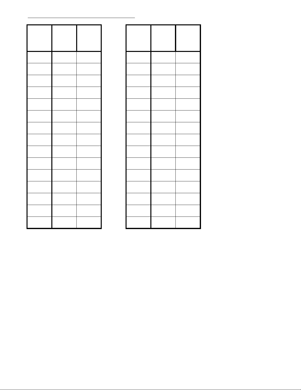
Program 2 - Line Group Assignment
(Display shows: LINE GROU P S)
(B.) Highest
Line # in
Group
#
(A.) Lowest
Line # in
Group
Line Group
01 16
02 17
03 18
04 19
05 20
06 21
07 22
08 23
09 24
10 25
Line Group
#
(A.) Lowest
Line # in
Group
(B.) Highest
Line # in
Group
11 26
12 27
13 28
14 29
15 30
Program Record Form Entry
1. Enter the lowest and highest line numbers
to be assigned in each line group.
System Program Entry
1. Ent er 02 (program nu mber).
2. Press *.
3. Enter the line group number.
4. Press *.
5. Enter the data from column A.
6. Press *.
7. Enter the data from column B.
8. Press *.
9. Enter the values for the next line group number OR
Press * to advance to another line gorup number OR
Press # to exit the program.
Options
(A.) Lowest L in e Number in Group
Line numbers: 01-system maximum
(B.) Highest Line Number in Group
Line numbers: 01-system maximum
- 2 -
Page 11
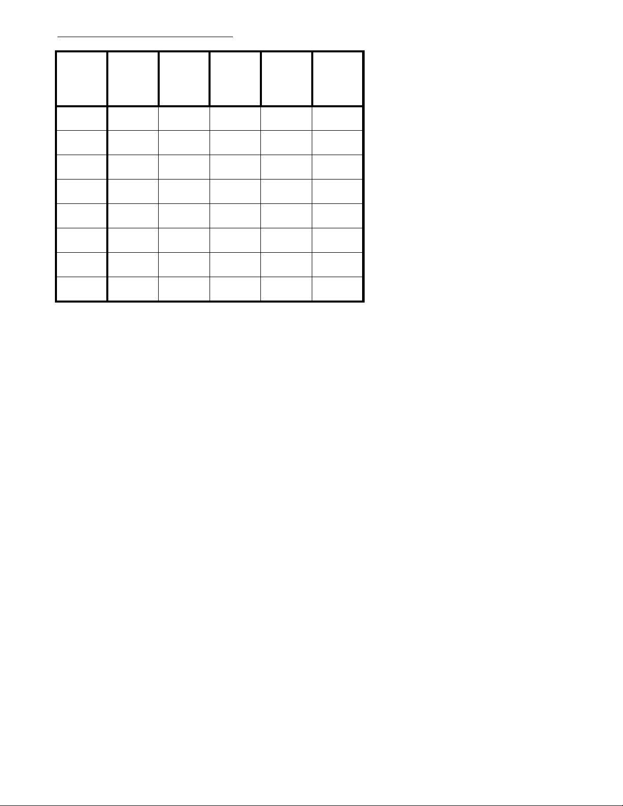
Program 3 - Line Options (2)
(Display shows: LINE ASSIGNMENT2)
Line #
01
02
03
04
05
06
07
08
Program Record Form Entry
1. Enter desired option number in each
feature's column.
(A.) DISA
Line
(B.) DISA
Access
Mode
(C.)
Common
Line Use
(D.) NonRestricted
Line
(E.) Caller
ID
Options
(A.) DISA Line
0=dis abled, 1=enabled
System Program Entry
1. Ent er 03 (program nu mber).
2. Press *.
3. Enter line number.
4. Press *.
5. Enter data from columns A-E.
6. Press *.
7. Next line number displays. Repeat steps 5-6 OR
Press * to advance to another line OR
Press # to exit program.
(B.) DISA Line Access Mode
0=no access, 1=day mode, 2=night mo d e,
3=day and night mode
(C.) Common Line Use
0=cannot use as a common line,
1=can use as a common line
(D.) Non-Restricted Line
0=restri cted, 1=non-restricted
(E.) Cal ler ID
0=dis abled, 1=enabled
- 3 -
Page 12
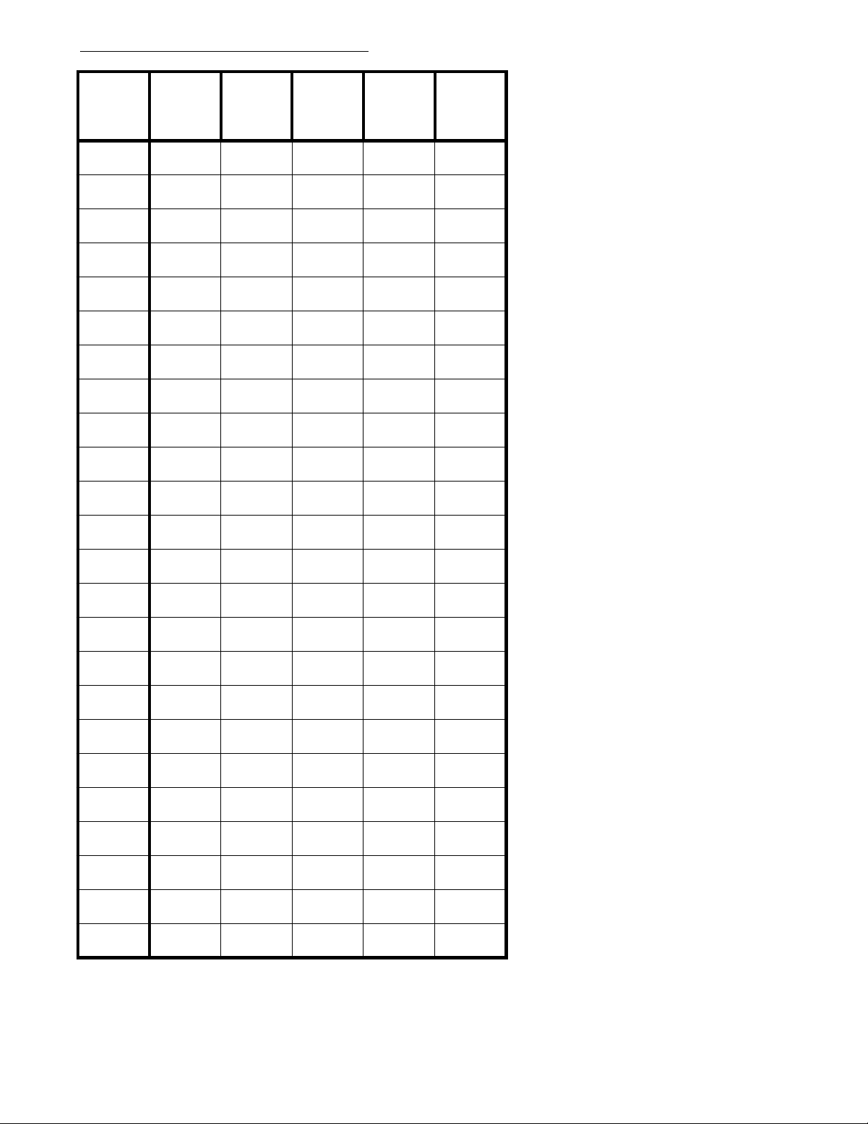
Program 4 - Extension Options (1)
(Display shows: STN ASSIGNMENT1)
Extension
Port #
10
11
12
13
14
15
16
17
18
19
(A.)
Executive
Override
(B.) CO
Off-Hook
Signaling
(C.)
Intercom
Off-Hook
Signaling
(D.)
Intercom
Signal Call
(E.) Headset
Options
(A.) Executive Override
0=not allowed, 1=allowed
with tone, 2=allowed
without tone
(B.) CO Off-Hook Signaling
0=dis abled, 1=enabled
(C.) Intercom Off-Hook Signaling
0=dis abled, 1=m anually
sent when busy, 2=automatically sent
when busy
(D.) Intercom Signaling
0=voice call, 1=forced ringing
(E.) Headset
0=dis abled, 1=enabled
20
21
22
23
24
25
26
27
28
29
30
31
32
Program Record Form Entry
1. Enter desired option number
in each feature's column.
System Program Entry
1. Ent er 04 (program
number).
2. Press *.
3. Enter extension port
number.
4. Press *.
5. Enter data from
columns A-E.
6. Press *.
7. Next extension port
displays. Repeat steps
5-6 OR
Press * to advance to
another extension
port OR
Press # to exit program.
33
- 4 -
Page 13

Program 5 - Unsupervised Conference Port
(Display shows: UNSUP.CONF.PORT)
Circuit
Number
01
02
03
04
Extension
Port #
Program Record Form Entry
1. Enter desired extension port for each Unsupervised
Conference circuit.
System Program Entry
1. Ent er 05 (program nu mber).
2. Press *.
3. Enter extension port number to be assigned to the
first Unsupervised Conference circuit.
4. Press *.
5. Enter the extension port to be assigned to the next
circuit number OR
Press * to advance to another circuit number OR
Press # to exit program.
- 5 -
Page 14
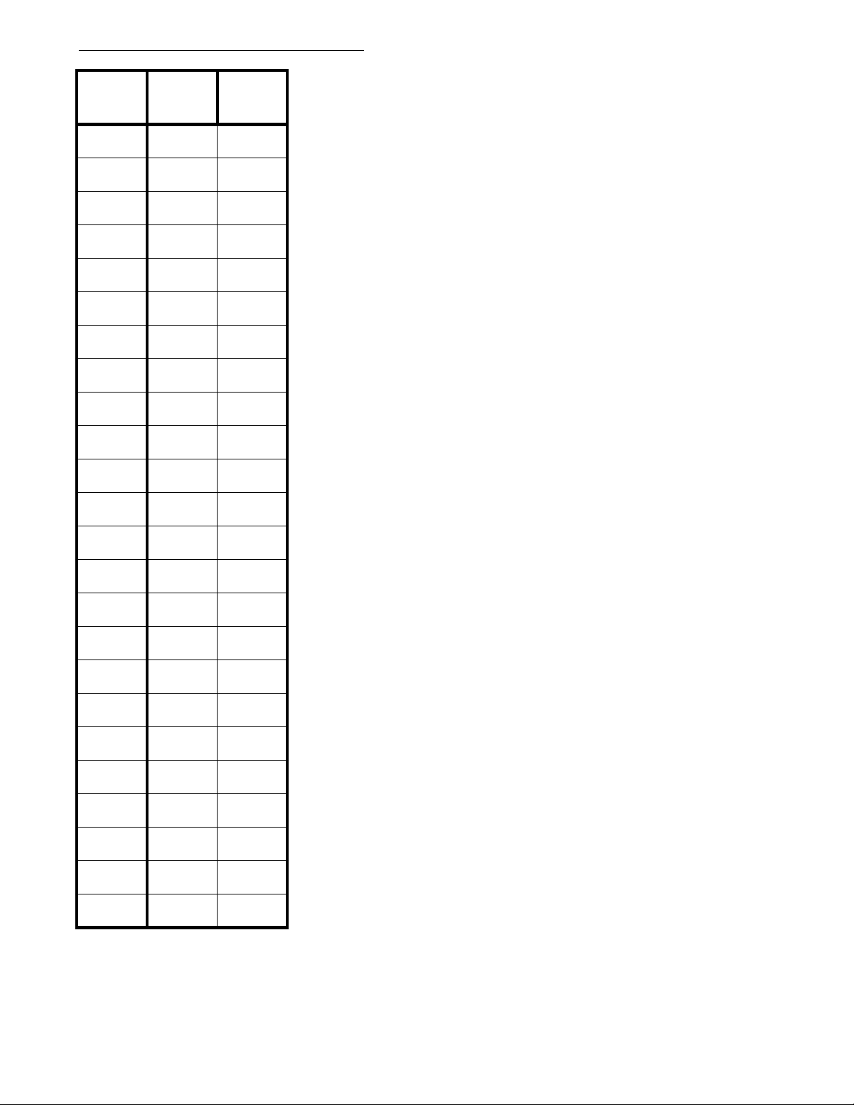
Program 6 - Outgoing Line Access
(Display shows: OUTGOING CO ACC.)
Extension
Port #
10
11
12
13
14
15
16
17
18
19
20
21
22
23
(A.) Line
Group #1
(B.) Line
Group #2
Options
(A.) Outgoing Line Group #1
00=no group assigned, 01-30=groups 1-30
(B.) Outgoing Line Group #2
00=no group assigned, 01-30=groups 1-30
Program Record Form Entry
1. Enter the outgoing line group numbers
(1 and 2) to be assigned to each
extension.
System Program Entry
1. Ent er 06 (program nu mber).
2. Press *.
3. Enter extension port number.
4. Press *.
5. Enter data from column A.
6. Press *.
7. Enter data from column B.
8. Press *.
9. Next extension port displays.
Repeat steps 5-8 OR
Press ** to advance to another
extension port OR
Press # to exit program.
24
25
26
27
28
29
30
31
32
33
- 6 -
Page 15
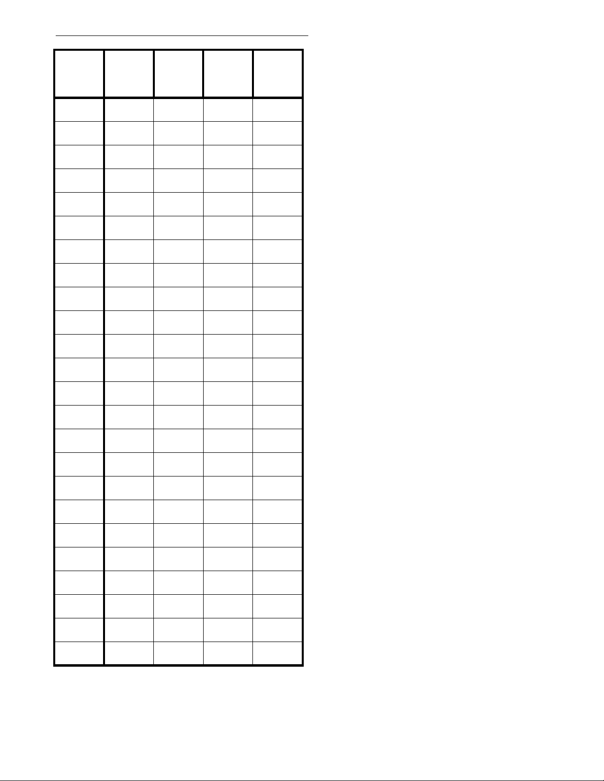
Program 7 - Incoming Line Access/Audible
(Display shows: INC.LINE ACC/AUD)
Extension
Port #
10
11
12
13
14
15
16
17
18
19
20
21
(A.) Line
Group #1
(B.) Ring
Type for
Line Group
#1
(C.) Line
Group #2
(D.) Ring
Type for
Line Group
#2
Options
(A.) Incoming Line Group #1
Enter first line group number [00=no
group assigned, 01-30=groups 1-30]
(B.) Ring Type for Line Group #1
0=no ringing, 1=day ringing, 2=night ringing,
3=day and night ringing
(C.) Incoming Line Group #2
Enter second line group number
[00=no group assigned, 01-30=groups
1-30]
(D.) Ring Type for Line Group #2
0=no ringing, 1=day ringing, 2=night ringing,
3=day and night ringing
Program Record Form Entry
1. For each extension, enter the
incoming line group numbers
(1 and 2) and the ring types to
be assigned to them.
22
23
24
25
26
27
28
29
30
31
32
33
System Program Entry
1. Ent er 07 (program nu mber).
2. Press *.
3. Enter extension port number.
4. Press *.
5. Enter data from columns A-B.
6. Press *.
7. Enter data from columns C-D.
8. Press *.
9. Next extension port displays.
Repeat steps 5-8 OR
Press ** to advance to another
extension port OR
Press # to exit program.
- 7 -
Page 16
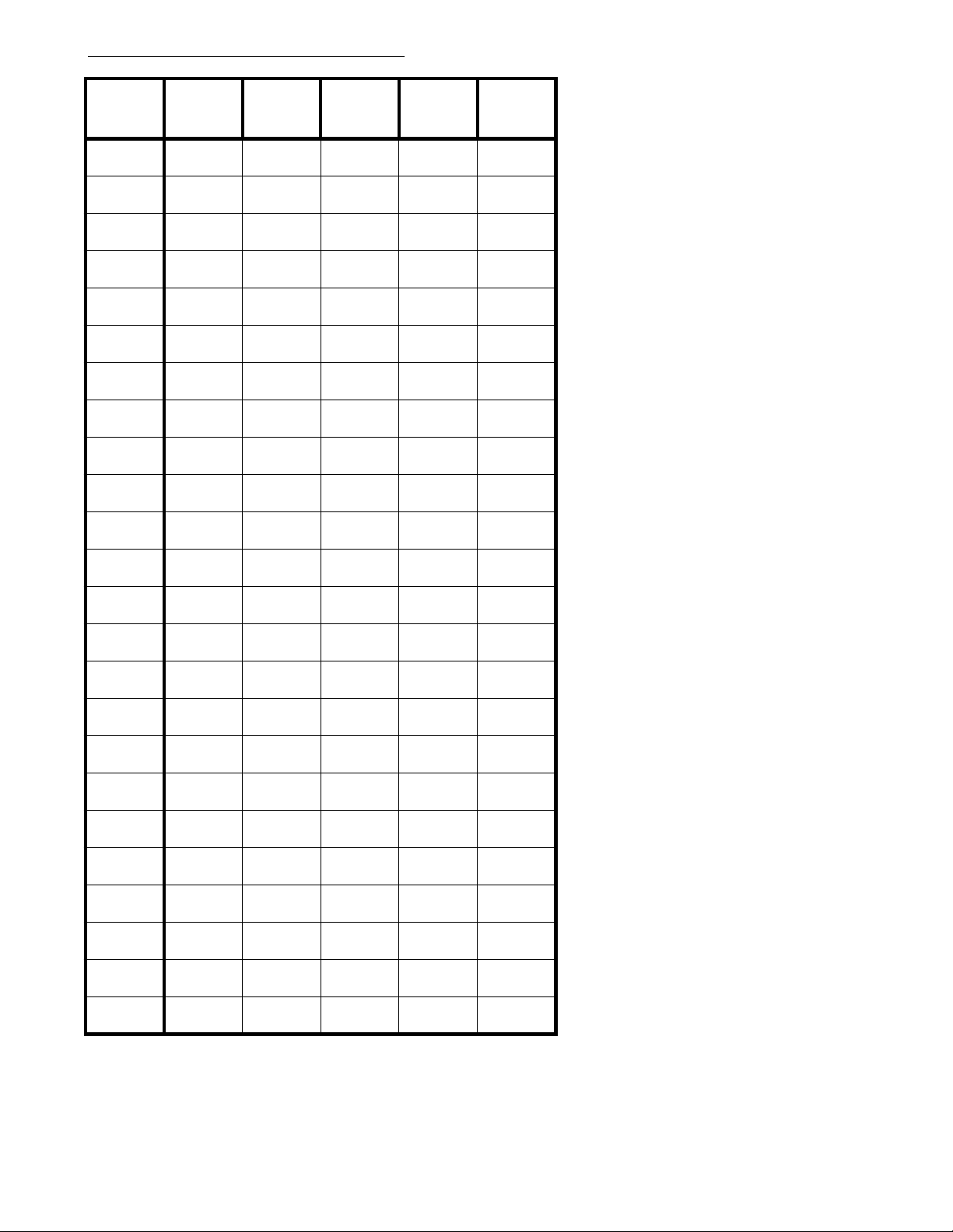
Program 8 - Extension Options (2)
(Display shows: STN ASSIGNMENT2)
Extension
Port #
10
11
12
13
14
15
16
17
18
19
20
(A.)
Instrument
Type
(B.) SLT
Dial Plan
(C.) Internal
Page Zone
(D.) Tenant
Group
(E.) Park
Group
Options
(A.) Instrument Type
0=KTS, 1=DISA, 2= S LT
(DP), 3=SLT (DTMF)
(B.) SLT Dial Plan Set
0=Dial Plan 1, 1=Dial Plan 2
(C.) Internal Page Zone
0=dis abled, 1=Page Zone 1,
2=Page Zone 2, 3=Page
Zone 3, 4=Page Zone 4
(D.) Tenant Group
0=dis abled, 1=Tenant
Group 1, 2=Tenant Group 2,
3=Tenant Group 3,
4=Tenant Group 4
(E.) Park G roup
0=dis abled, 1=Park Group
1, 2=Park Group 2, 3=Park
Group 3, 4=Park Group 4
21
22
23
24
25
26
27
28
29
30
31
32
33
Program Record Form Entry
1. Enter the desired
option number in each
feature's column.
System Program Entry
1. Ent er 08 (program
number).
2. Press *.
3. Enter extension port
number to be
programmed.
4. Press *.
5. Enter data from
columns A-E.
6. Press *.
7. The next extension
port displays.
Repeat steps 5-6 OR
Press * to advance to
another extension port
OR
Press # to exit
program.
- 8 -
Page 17

Program 9 - Executive Call Forward
(Display shows: EXEC. CALL FWD)
Executive
Call
Forward
Pair
1
2
3
4
5
6
7
8
Program Record Form Entry
1. Enter the extensions for the executive and secretary pairs.
System Program Entry
1. Ent er 09 (program nu mber).
2. Press *.
3. Enter the data from column A.
4. Press *.
5. Enter data from column B.
6. Press *.
7. Next Call Forwarding Pair number displays. Repeat steps 3-6 OR
Press * to advance to another Call Forwarding Pair OR
Press # to exit program.
(A.)
Executive
Extension
Port #
(B.)
Secretary
Extension
Port #
Options
(A.) Executive Extension Port #
00=none, 10-system maximum= extension
port number
(B.) Secretary Extension Port #
00=none, 10-system maximum= extension
port number
- 9 -
Page 18
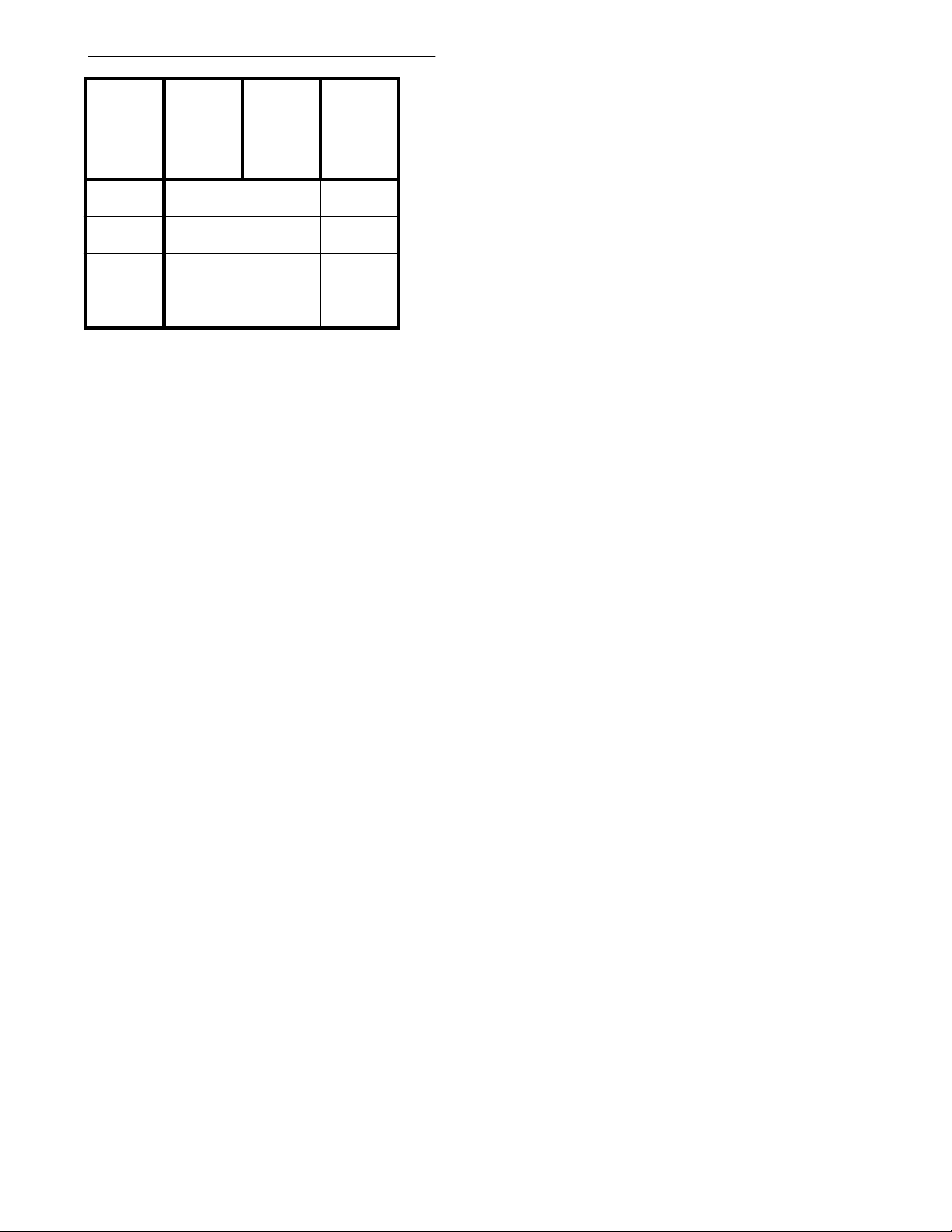
Program 10 - Dual Handsfree Hotline
(Display shows: DUAL HF HOTLINE)
(A.)
Dual HF
Hotline Pair
1
2
3
4
Program Record Form Entry
1. Enter the extensions for the executive and secretary pairs.
System Program Entry
1. Ent er 10 (program nu mber).
2. Press *.
3. Enter the data from column A.
4. Press *.
5. Enter data from column B.
6. Press *.
7. Enter data from column C.
8. Press *.
9. Enter next Dual Handsfree Hotline pair by repeating steps 3-8 OR
Press # to exit program.
Secretary
Extension
Port #
(B.)
Executive
#1
Extension
Port #
(C.)
Executive
#2
Extension
Port #
Options
(A.) Secretary Extension Port #
00=none, 10-system maximum=
extension port number
(B.) Executive #1 Extension Port #
00=none, 10-system maximum=
extension port number
(C.) Executive #2 Extension Port #
00=none, 10-system maximum=
extension port number
- 10 -
Page 19
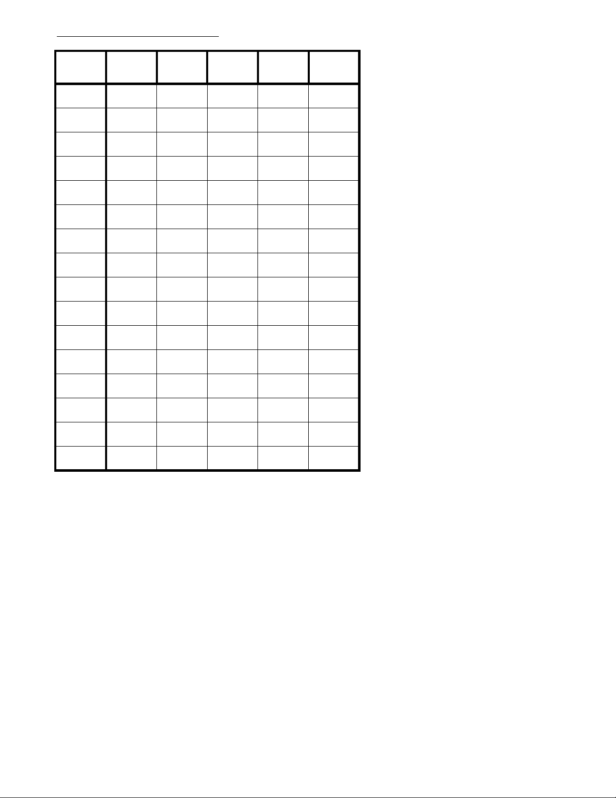
Program 11 - Hunt Groups
(Display shows: HUNT GROUP S)
Ext. # in
Hunt Group
1
2
3
4
5
6
7
8
9
10
11
Hunt Group0Hunt Group1Hunt Group2Hunt Group3Hunt Group
4
12
13
14
15
16
Program Record Form Entry
1. Enter the extensions to be assigned to each Hunt Group.
System Program Entry
1. Ent er 11 (program nu mber).
2. Press *.
3. Enter the Hunt Group number (0-4) to be programmed.
4. Press *.
5. Enter the first extension port for that particular Hunt Group.
6. Press *.
7. Continue entering extension ports for the Hunt Group as in steps 5-6.
8. When all extensions are entered, continue pressing * through the 16th extension to continue with the next
group or press # to exit the program.
9. Enter next Hunt Group by repeating steps 3-8 OR
Press # to exit program.
- 11 -
Page 20
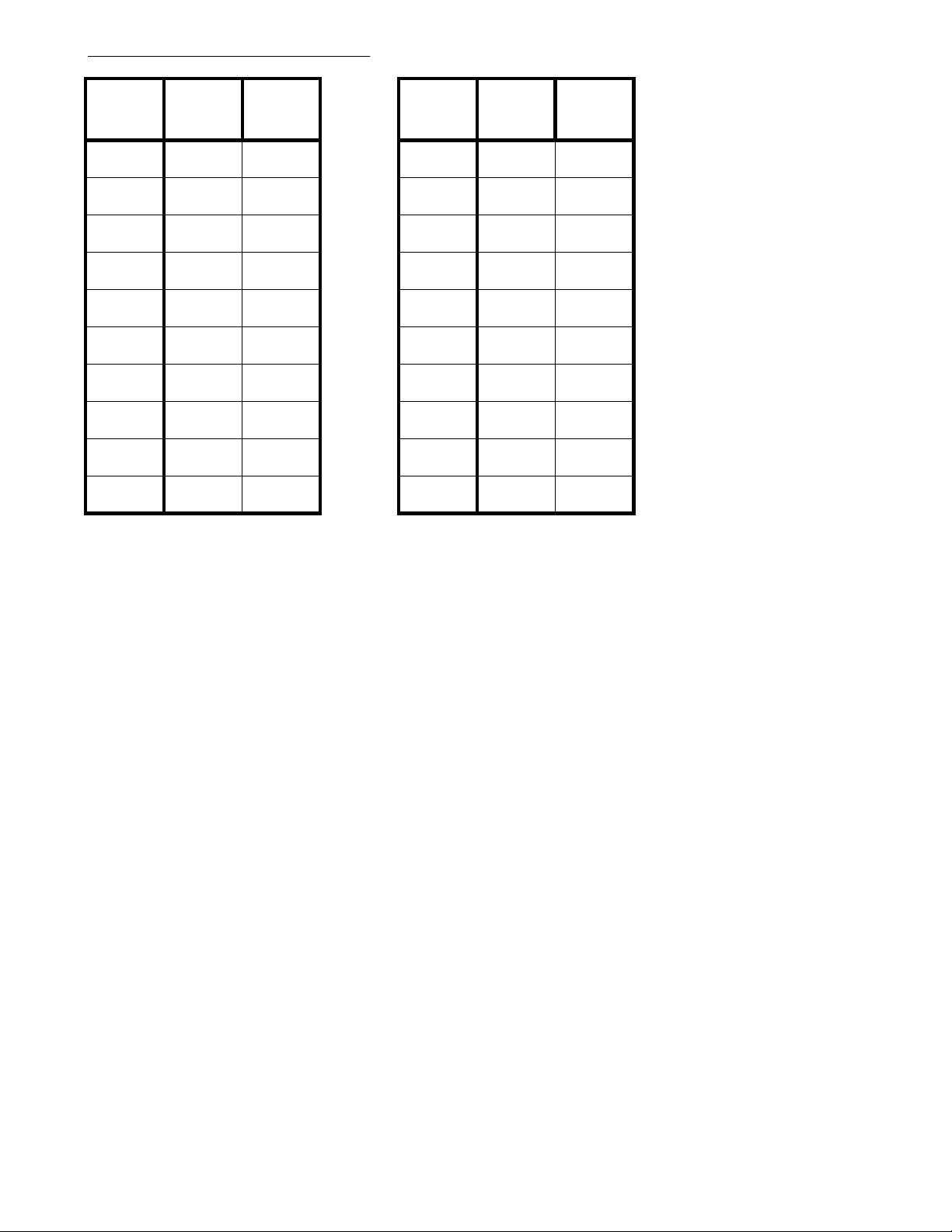
Pr og ram 12 - Door Chime Box
(Display shows: DOOR CHIME BOX)
Door Box #1(A.)
Extension #
11
22
33
44
55
66
77
88
99
10 10
Program Record Form Entry
1. Enter the required extensions for each Door Box
and assign the ring type each extension
should receive.
System Program Entry
1. Ent er 12 (program nu mber).
2. Press *.
3. Enter the Door Box number (1 or 2) to be programmed.
4. Press *.
5. Enter the first extension port to be assigned and its ring type.
6. Press *.
7. Continue entering extension ports and ringing assignments
through the tenth extension port.
If no other extensions need to be entered, press * through the
tenth extension or press # to exit the program.
8. To enter the next Door Box number repeat steps 3-7 OR
Press # to exit program.
(B.) Ring
Type
Door Box
#2
(A.)
Extension #
(B.) Ring
Type
Options
(A.) Extension Port #
00=none, 10-system
maximum=extension port number
(B.) Ring Type
0=no ringing, 1=day ringing,
2=night ringing, 3=day and night ringing
- 12 -
Page 21
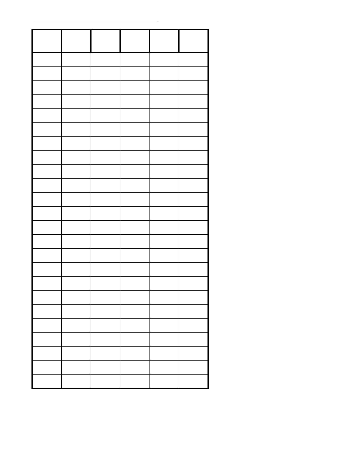
Program 13 - Extension Options (3)
(Display shows: STN ASSIGNMENT3)
Extension
Port #
10
11
12
13
14
15
16
17
18
19
20
(A.)
Confirm.
Tone
(B.) Do Not
Disturb
(C.) Alarm
Audible
(D.) Voice
Announce
Device Port
(E.)
Terminal
Connection
Options
(A.) Confirmation Tone
0=ena bled, 1=disabled
(B.) Do Not Disturb
0=dis abled, 1=incoming CO
calls blocked, 2=CO and
ICM calls blocked, 3=CO
and ICM calls blocked or
CO calls blocked and ICM
calls allowed
(C.) Alarm Audible
0=dis abled, 1=enabled
(D.) Voice Announce Device Port
0=dis abled, 1=enabled
(E.) Terminal Connection
0=not connected,
1=connected
21
22
23
24
25
26
27
28
29
30
31
32
33
Program Record Form Entry
1. Enter the desired option
number in for each featu re.
System Program Entry
1. Ent er 13 (program
number).
2. Press *.
3. Enter extension port
number.
4. Press *.
5. Enter data from
columns A-E.
6. Press *.
7. The next extension
port displays. Repeat
steps 5-6 OR
Press * to advance
to another extension
port OR
Press # to exit
program.
- 13 -
Page 22
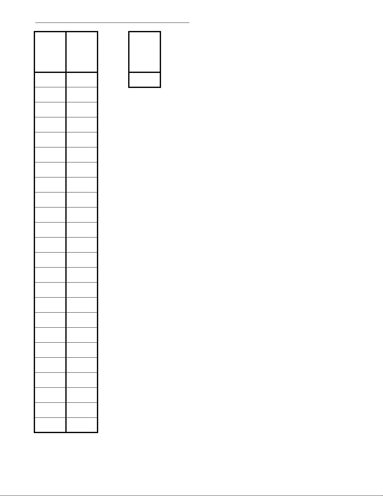
Program 14 - Flexible Station Numbering
(Display shows: FLEX.STA.#ING)
Extension
Port #
10
11
12
13
14
15
16
17
18
19
20
21
22
(A.)
Extension
Number
Assigned to
Port
(B.) Number
Plan
Options
(A.) Extension Number Port Assignment
10-79 = 2-digit number plan extensio ns,
110-799 = 3-digit number plan extensio ns
(B.) Number Plan
002 = 2-digit number plan assignme nt,
003 = 3-digit number plan assignme nt
Program Record Form Entry
1. Enter the extension numbers to
be assigned to each port, and
assign the number plan.
System Program Entry
To ch an ge port assignme n t s:
1. Ent er 14 (program nu mber).
2. Press *.
3. Enter data from column A.
4. Press *.
5. Enter the next extension port number
to be assigned by repeating steps 5-6 OR
Press * to skip the displayed port OR
Press # to exit program.
23
24
25
26
27
28
29
30
31
32
33
To change the system numbering plan:
1. Ent er 14 (program nu mber).
2. Press * *.
3. Enter the data from column B.
4. Press *.
5. Press # to exit program.
- 14 -
Page 23
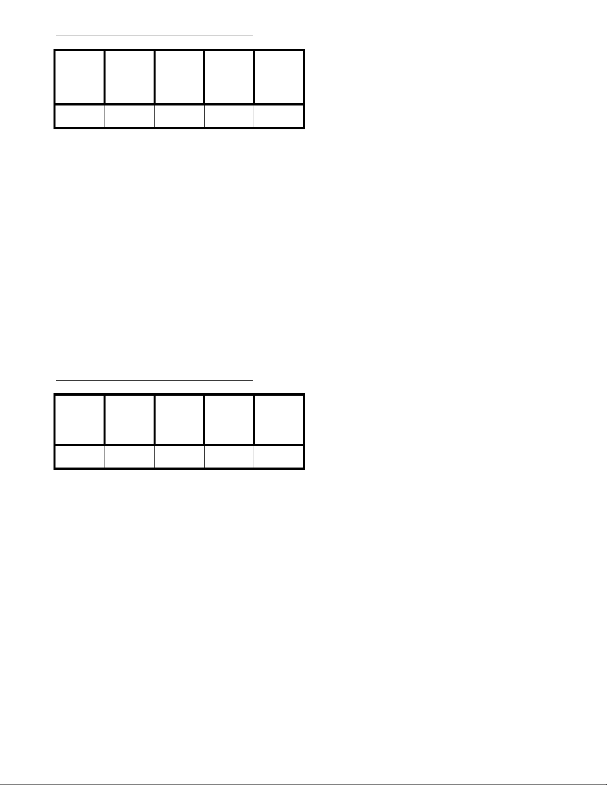
Program 15 - System Options (1)
(Display shows: SYS ASSIGNMENT1)
(A.) Flexible
Line
Appearance
Program Record Form Entry
1. Enter desired option number in each
feature's column.
System Program Entry
1. Ent er 15 (program nu mber).
2. Press *.
3. Enter the data from columns A-E.
4. Press *.
5. Press # to exit the program.
(B.) Night
Transfer
(C.)
Automatic
Line Access
(D.)
Exclusive
Hold
(E.) Single
Step Access
Options
(A.) Flexible Line Appearance
0=dis abled, 1=enabled
(B.) Night Transfer
0=all tenants, 1=each tenant
(C.) Automatic Line Access
0=dis abled, 1=press SPK key and
queuing group number, 2=dial 0 from
on-hook condition, 3=press SPK key
and queuing group number and dial 0
from on-hook condition
(D.) Exclusive Hold
0=dis abled, 1=enabled
(E.) Single Step Access
0=dis abled, 1=enabled
Program 16 - System Options (2)
(A.) Ringing
Line
Preference
Program Record Form Entry
1. Enter desired option number in each feature's column.
System Program Entry
1. Ent er 16 (program nu mber).
2. Press *.
3. Enter the data from columns A-E.
4. Press *.
5. Press # to exit the program.
(B.)
Recalling
Line
Preference
(C.) Allow
SLT to
Access Line
on Hold
(D.)
Add-On
Conference
Setup Mode
Multi-Line
Conference
(Display shows: SYS ASSIGNMENT2)
Options
(E.)
(A.) Ringing Line Preference
0=disabled, 1=all incoming calls to Group
1 and ringing incoming calls to Group 2,
2=incoming ringing calls to Group 1 and
Group 2
(B.) Recalling Line Preference
0=dis abled, 1=enabled
(C.) Allow SLT to Access Line on Hold
0=no access for line on hold, 1=can
access line on hold
(D.) Add-On Conference Setup Mode
0=increase one by one, 1=increase 5
parties at once
(E.) Multi=Line Conference
0=dis abled, 1=enabled
- 15 -
Page 24
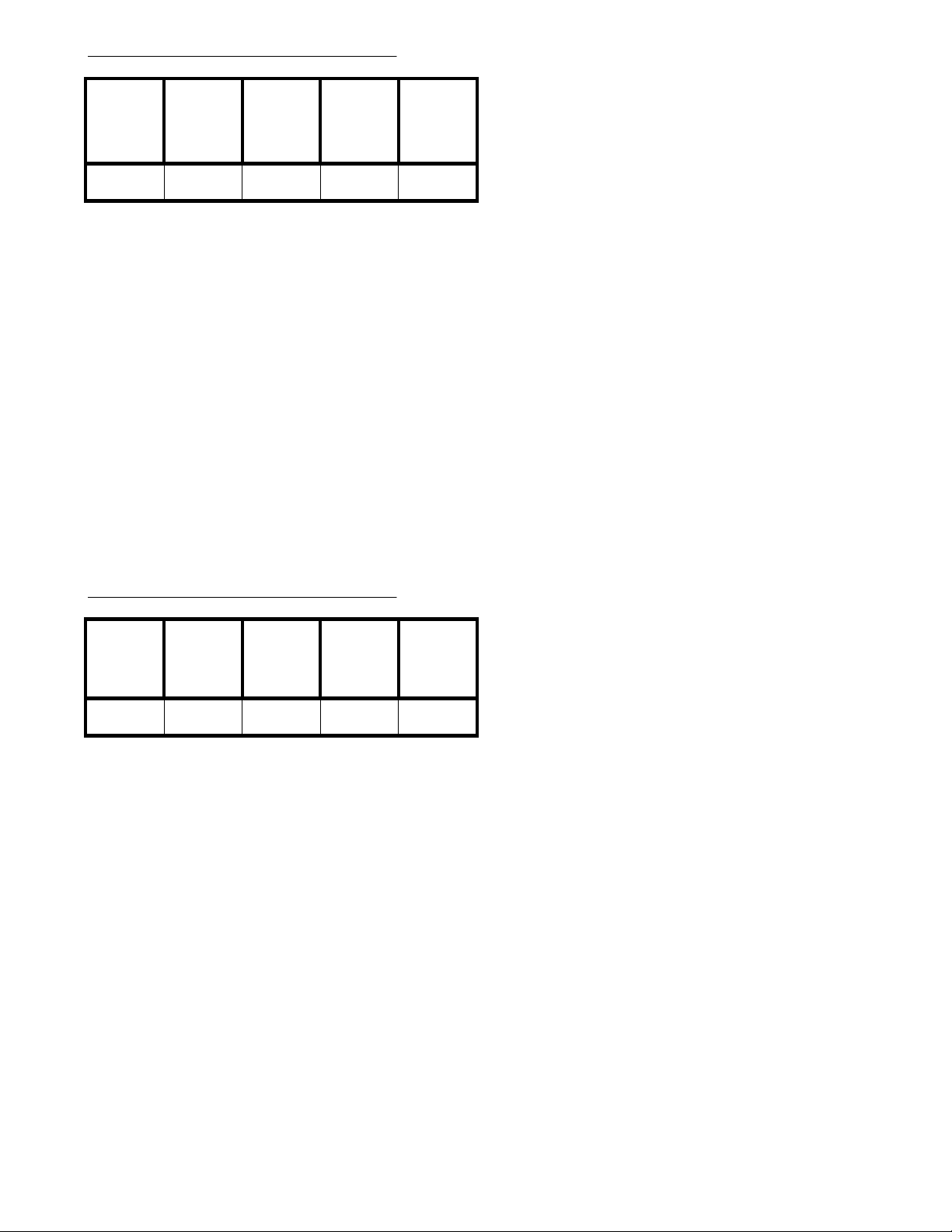
Program 17 - System Options (3)
(Display shows: SYS ASSIGNMENT3)
(A.) Dial
Pulse
Sender
Speed
Program Record Form Entry
1. Enter desired option number in each feature's column.
System Program Entry
1. Ent er 17 (program nu mber).
2. Press *.
3. Enter the data from columns A-E.
4. Press *.
5. Press # to exit the program.
(B.)
Make/Break
Ratio
(C.) DTMF
Duration
(D.) Storage
Quantity of
Speed Dial
Existence of
Attendant
for DISA
(E.)
Options
(A.) Dial Pulse Sender Speed
0=10 PPS, 1=20 PPS
(B.) Make/Break Ratio
0=33%, 1=39%
(C.) DTMF Duration
0=high speed (80 ms On - 80 ms Off),
1=mi d speed (100 ms On - 100 ms Off) ,
2=low speed (150 ms On - 150 ms Off)
(D.) Storage Quantity of Speed Dial
0=100 (numbers range from 00-99), 1=200
(numbers range from 000-199)
(E.) Existence of Attendant for DISA
0=none, 1=day mode, 2=night mode,
3=day and night mode
Program 18 - System Options (4)
(A.) Three
Minute
Warning
Tone
Program Record Form Entry
1. Enter desired option number in each feature's column.
System Program Entry
1. Ent er 18 (program nu mber).
2. Press *.
3. Enter the data from columns A-E.
4. Press *.
5. Press # to exit the program.
(B.) Not
Used
0
(C.) Speed
Dialing
Restriction
(D.)
Handset
Receiver
Volume
(E.) Time
Indication
(Display shows: SYS ASSIGNMENT4)
Options
(A.) Three Minute Warning Tone
0=dis abled, 1=enabled
(B.) Not Used
Must be set to "0"
(C.) Speed Dialing Restriction
0=not restricted, 1=restricted
(D.) Handset Receiver Volume
0=reset after conversation, 1=keep
current volume
(E.) Time Indication
0=12 hour mode, 1=24 hour mode
- 16 -
Page 25
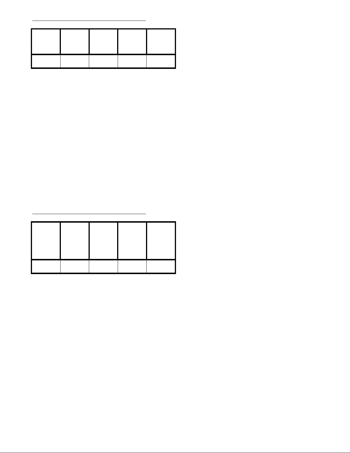
Program 19 - System Options (5)
(Display shows: SYS ASSIGNMENT5)
(A.) All Call
to External
Zone
Program Record Form Entry
1. Enter desired option number in each feature's column.
System Program Entry
1. Ent er 19 (program nu mber).
2. Press *.
3. Enter the data from columns A-E.
4. Press *.
5. Press # to exit the program.
(B.)
Intercom
Signaling
(C.)
Microphone
On/Off
(D.) Room
Monitor
(E.) Not
Used
0
Options
(A.) All Call to External Zone
0=dis abled, 1=speaker 1,
2=speaker 2, 3=speaker 1 and 2
(Option 2 and 3 not used in
Portrait 308)
(B.) Intercom Signaling
0=voice call, 1=forced ring signal
(C.) Microphone On/Off
0=on, 1=off
(D.) Room Monitor
0=dis abled, 1=enabled
(E.) Not Used
Must be set to "0"
Program 20 - System Options (6)
(D.)
(A.) Door
Chime Tone
Duration
Program Record Form Entry
1. Enter desired option number in each feature's column.
System Program Entry
1. Ent er 20 (program nu mber).
2. Press *.
3. Enter the data from columns A-E.
4. Press *.
5. Press # to exit the program.
(B.) Paging
Splash Tone
(C.) Door
Alert Tone
Automatic
Line Access
Code for
SLT
Existence of
Door Box
(E.)
(Display shows: SYS ASSIGNMENT6)
Options
(A.) Door Chime Tone Duration
0=2 times, 1=30 seconds
(B.) Paging Splash Tone
0=dis abled, 1=enabled
(C.) Door Alert Tone
0=dis abled, 1=enabled
(D.) Automatic Line Access Code
for SLT
0=off-hook and dial 0, 1=offhook and dial 9
(E.) Door Box
0=none, 1=Door Box 1 enabled,
2=Door Box 2 enabled, 3=Door
Box 1 and 2 enabled
- 17 -
Page 26
Program 21 - Exclusive Hold Timers
(Display sh ows: EXC.HOLD TIMERS)
(2.) Recall
(1.) Recall
Start Time
Program Record Form Entry
1. Enter desired option number in each feature's column.
System Program Entry
1. Ent er 21 (program nu mber).
2. Press *.
3. Enter the option number to be programmed (1 or 2).
4. Press *.
5. Enter the value for the option being programmed.
6. Press *.
7. If the first option number entered was '1', you can enter the value for option number '2' OR
Press # to exit the program.
Signal
Duration
Time
Options
(1.) Recall Start Time
000=not assigned, 001-225 =
10-2550 seconds
(2.) Recall Signal Duration Time
000=not assigned, 001-225 =
1-255 seconds
Program 22 - System Hold Timers
(1.) Recall
Timer
Program Record Form Entry
1. Enter desired option number in each feature's column.
System Program Entry
1. Ent er 22 (program nu mber).
2. Press *.
3. Enter the option number to be programmed (1 or 2).
4. Press *.
5. Enter the value for the option being programmed.
6. Press *.
7. If the first option number entered was '1', you can enter the value for option number '2' OR
Press # to exit the program.
(2.)
Duration
Timer
(Display shows: SYS.HOLD TIMERS)
Options
(1.) Recall Timer
000=not assigned, 001-225 =
10-2550 seconds
(2.) Durat ion Timer
000=not assigned, 001-225 =
1-255 seconds
- 18 -
Page 27
Program 23 - Unscreened Transfer Recall
(Display shows: UNANN.XFER TIMER)
Unscreened
Transfer
Recall
Timer
Program Record Form Entry
1. Enter desired value for the timer.
System Program Entry
1. Ent er 23 (program nu mber).
2. Press *.
3. Enter the value for the timer.
4. Press *.
5. Press # to exit the program.
Options
Unscreened Transfer Recall Timer
000=dis abled, 001 - 255 = 10-2550
seconds
Program 24 - Screened Transfer Recall
Screened
Transfer
Timer
Program Record Form Entry
1. Enter desired value for the timer.
System Program Entry
1. Ent er 24 (program nu mber).
2. Press *.
3. Enter the value for the timer.
4. Press *.
5. Press # to exit the program.
(Display shows: ANN'D XFER TIMER)
Options
Screened Transfer Recall Timer
000=dis abled, 001 - 255 =
10-2550 seconds
- 19 -
Page 28
Program 25 - Call Duration Timer
(Display shows: CALL DUR. START)
Call
Duration
Timer
Program Record Form Entry
1. Enter desired value for the timer.
System Program Entry
1. Ent er 25 (program nu mber).
2. Press *.
3. Enter the value for the timer.
4. Press *.
5. Press # to exit the program.
Options
Call Duration Timer
000=dis abled, 001 - 180 = 1-180 seconds
Program 26 - Flash Timer
(2.) PBX/
(1.) CO Line
Flash Timer
Program Record Form Entry
1. Enter desired option number in each feature's column.
System Program Entry
1. Ent er 26 (program nu mber).
2. Press *.
3. Enter the option number to be programmed.
4. Press *.
5. Enter the value for the option being programmed.
6. Press *.
7. If the first option number entered was '1', you can enter the value for option number '2' OR
Press # to exit the program.
Centrex
Line Flash
Timer
(Display shows: FLASH TIMER)
Options
(1.) CO Line Flash Timer
000 = not assigned, 001 - 250 =
10 - 2500 ms
(2.) PBX/Centrex Line Flash Timer
000 = not assigned, 001 - 250 =
10 - 2500 ms
- 20 -
Page 29
Program 27 - SMD R T ime r
(Display shows: SMDR TIMERS)
(1.) Call
Duration
Timer
Program Record Form Entry
1. Enter desired option number in each feature's column.
System Program Entry
1. Ent er 27 (program nu mber).
2. Press *.
3. Enter the value for the Call Duration Timer.
4. Press *.
5. Enter the value for the Call Start Timer.
6. Press *.
7. Press # to exit the program.
(2.) Call
Start Timer
Options
(1.) Call Duration Timer
00 = starts immediately,
01 - 60 = 1 - 60 seconds
(2.) Call Start Timer
00=starts immediately,
01 - 60 = 1 - 60 seconds
Program 28 - Call Forward Transfer Timer
Call
Forward
Transfer
Timer
Program Record Form Entry
1. Enter desired value for the timer.
System Program Entry
1. Ent er 28 (program nu mber).
2. Press *.
3. Enter the value for the timer.
4. Press *.
5. Press # to exit the program.
(Display shows: DELAY RING TIMER)
Options
Delay Ring Transf er Timer
000=dis abled, 001 - 255 = 1-255 seconds
- 21 -
Page 30
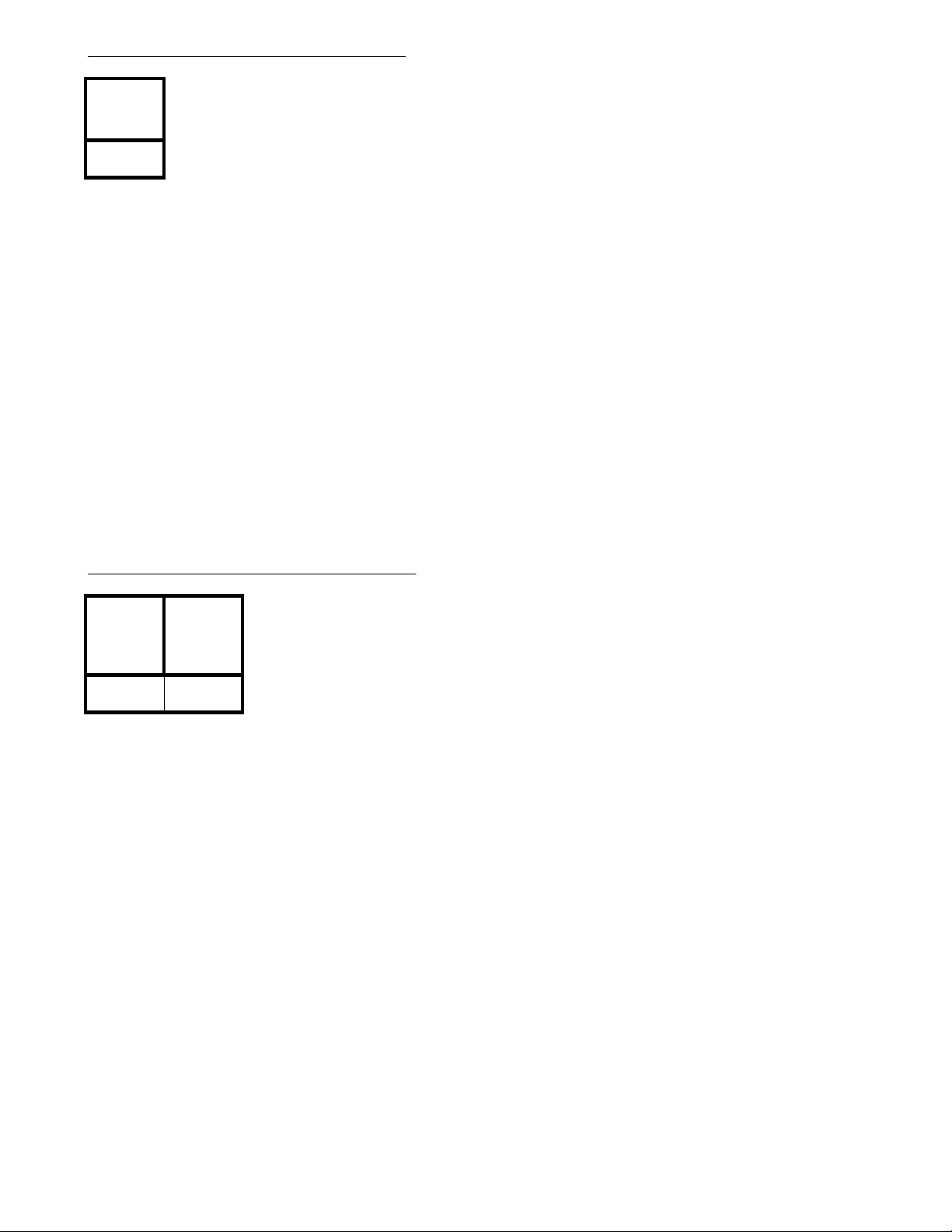
Program 29 - Attendant Reverting
(Display shows: ATT.REVERT TIMER)
Attendant
Revert
Timer
Program Record Form Entry
1. Enter desired value for the timer.
System Program Entry
1. Ent er 29 (program nu mber).
2. Press *.
3. Enter the value for the timer.
4. Press *.
5. Press # to exit the program.
Options
Attendant Revert Timer
000=dis abled, 001 - 255 = 1-255 seconds
Program 30 - Voice Message Timer
(1.)
Automatic
Answering
Timer
Program Record Form Entry
1. Enter desired option number in each feature's column.
System Program Entry
1. Ent er 30 (program nu mber).
2. Press *.
3. Enter the option number (1 or 2) for the timer to be programmed.
4. Press *.
5. Enter the value for the timer being programmed.
6. Press *.
7. If the first option number entered was '1', you can enter the value for option number '2' OR
Press # to exit the program.
(2.) Dial
Tone Sent
Timer
(Display shows: ANN.TIMERS)
Options
(1.) Automatic Answering Timer
000=dis abled, 001 - 255 = 1 - 255
seconds
(2.) Dial Tone Sent Timer
000=dis abled, 001 - 255 = 1 - 255
seconds
- 22 -
Page 31
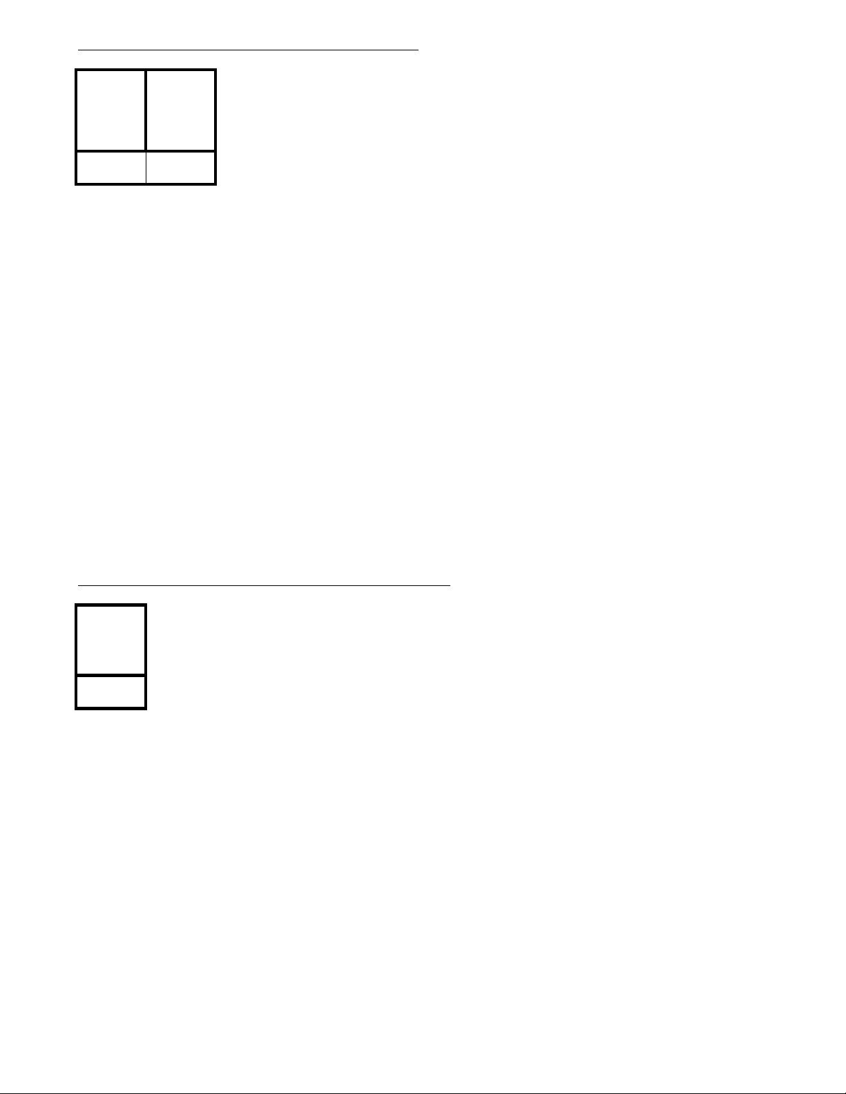
Program 31 - Line to Line Cut-Off Time r
(Display shows: LN.TO LN.TIMERS)
(1.) Path
Connection
Waiting
Timer
Program Record Form Entry
1. Enter desired option number in each feature's column.
System Program Entry
1. Ent er 31 (program nu mber).
2. Press *.
3. Enter the option number (1 or 2) for the timer to be programmed.
4. Press *.
5. Enter the value for the timer being programmed.
6. Press *.
7. If the first option number entered was '1', you can enter the value for option number '2' OR
Press # to exit the program.
(2.)
Warning
Tone Timer
for Conv.
Cut-Off
Options
(1.) Path Connection Waiting Timer
000=dis abled, 001 - 255 = 1 - 255
seconds
(2.) Warning Tone Timer for
Conversation Cut-Off
000=dis abled, 001 - 255 = 1 - 255
minutes
Program 32 - DTMF Receiver Release Timer
DTMF
Receiver
Release
Timer
Program Record Form Entry
1. Enter desired value for the timer.
System Program Entry
1. Ent er 32 (program nu mber).
2. Press *.
3. Enter the value for the timer.
4. Press *.
5. Press # to exit the program.
(Display sho ws: PB REC.REL.TIMER)
Options
DTMF Receiver Release Timer:
000=dis abled, 001 - 255 = 1 - 255
seconds
- 23 -
Page 32
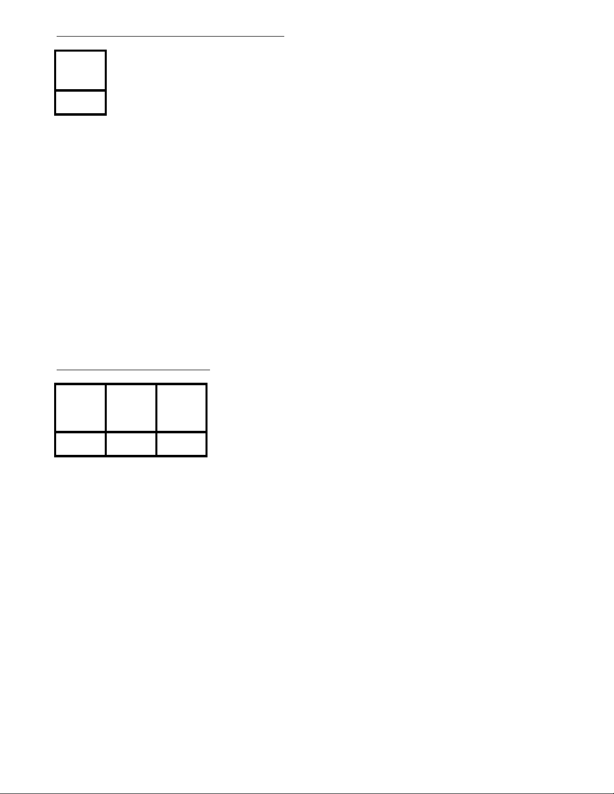
Program 33 - LND/Repeat Dial Timer
(Display shows: LINE DROP TIMER)
LND/
Repeat Dial
Timer
Program Record Form Entry
1. Enter desired value for the timer.
System Program Entry
1. Ent er 33 (program nu mber).
2. Press *.
3. Enter the value for the timer.
4. Press *.
5. Press # to exit the program.
Options
Last Number Redial/Repeat
Dial Timer:
000=dis abled, 001 - 010 =
1-10 seconds
Program 34 - Repeat Dial
(1.) Waiting
Time
Between
Recall
Program Record Form Entry
1. Enter desired value for the counter.
System Program Entry
1. Ent er 34 (program nu mber).
2. Press *.
3. Enter the value for the option.
4. Press *.
5. Press # to exit the program
(2.) Calling
Time
(3.) Number
of Times
Redialed
(Display shows: REP.DIAL.TIMES)
Options
(1.) Waiting Time Between Recall
000 = No Function , 001-255 =
1-255 Seconds
(2.) Calling Time
000 = No Function , 001-255
Seconds
(3.) Number of Times Redialed
001-255 = 1-255 times
- 24 -
Page 33
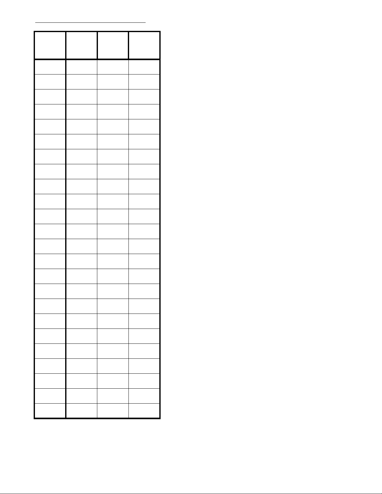
Program 35 - Class of Service
(Display sh ows: CLASS OF SERVICE)
Extension
Port #
10
11
12
13
14
15
16
17
18
19
20
21
22
(A.) Day
Mode
(B.) Night
Mode
(C.) Dial
Block Class
Options
Enter one of the following Class of Service levels for
options (A.), (B.), and (C.):
0 = No Restrictions
1 = Restricted by Program 40 [4 codes, 4 digits long).
Allows calls matching PBX extension and
Common Unrestricted Codes (Program 39).
2 = Restricted by Program 41 [8 codes, 4 digits long).
Allows Permitted Codes (Program 36), PBX
extension calls and Common Unrestricted
Codes (Program 39).
3 = Restricted byProgram 37 and Program 41
[8 Codes, 2 digits long].
Allows PBX extension calls and Common
Unrestricted Codes (Program 39).
4 = Restricts all outgoing calls.
Allows PBX extension calls and Common
Unrestricted Codes (Program 39).
5 = Restricted to Intercom calls only.
Program Record Form Entry
1. Enter the desired Class of Service number
in each feature's column.
23
24
25
26
27
28
29
30
31
32
33
System Program Entry
1. Ent er 35 (program nu mber).
2. Press *.
3. Enter the extension port to be programmed.
4. Press *.
5. Enter data from columns A-C.
6. Press *.
7. Enter the data for the next extension port
displayed OR
Press * to skip the displayed extension
port OR
Press # to exit program.
- 25 -
Page 34
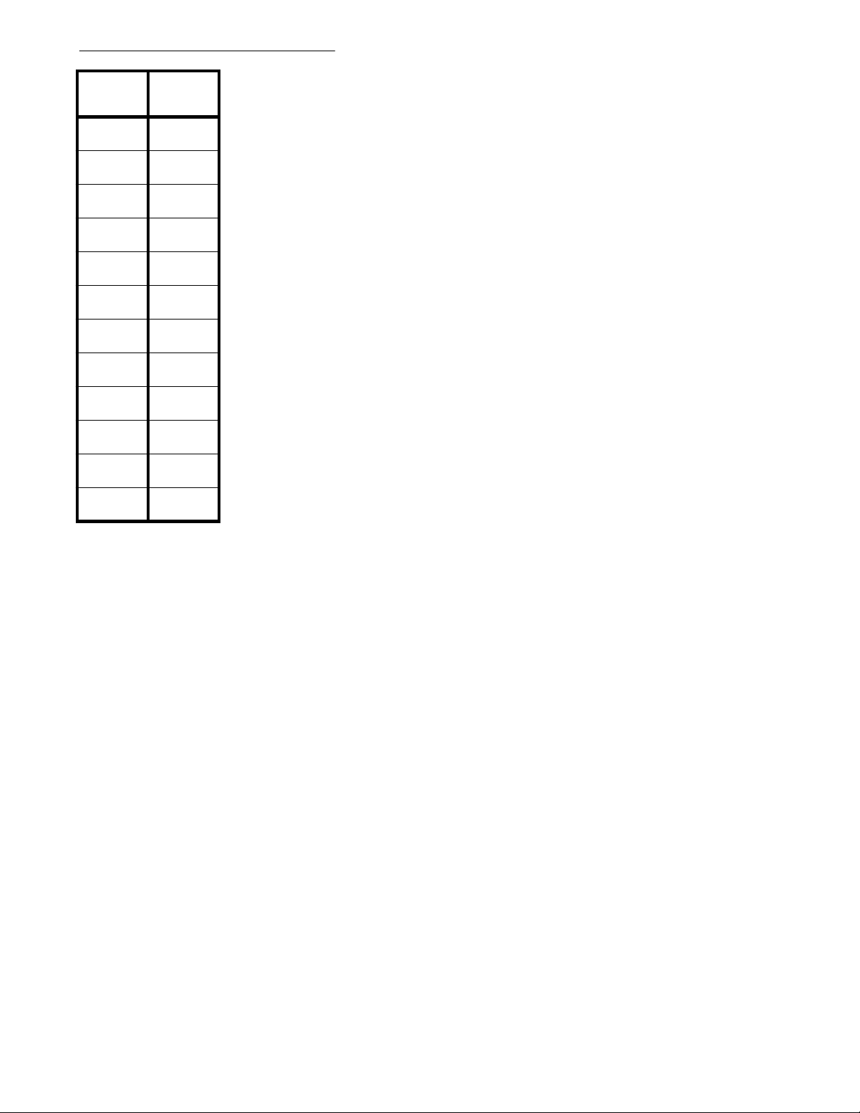
Program 36 - Per mitte d C odes
(Display shows: PERMITTED CODES)
Permitted
Code #
01
02
03
04
05
06
07
08
09
10
11
Permitted
Codes
12
Program Record Form Entry
1. For each Permitted Code, program up to the first 8 digits of an allowed telephone number. Use 'DC'
as a 'Don't Care' digit within the 8 digits if it doesn't matter what number is dialed.
System Program Entry
1. Ent er 36 (program nu mber).
2. Press *.
3. Enter the Permitted Code number (01-12) to be programmed.
4. Press *.
5. Enter the value for the code being programmed.
6. Press *.
7. Enter the value for the next Permitted Code OR
Press * to skip to the next code OR
Press # to exit the program.
- 26 -
Page 35
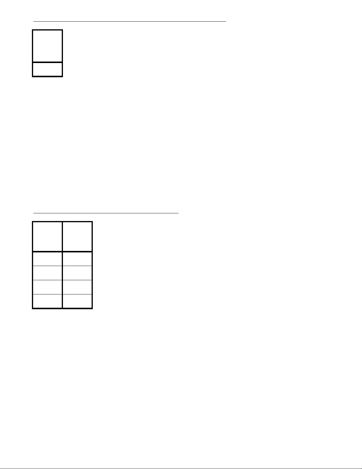
Program 37 - COS 3 Allowed Number of Dialed Digits
(Display sh ows: DIGIT LIMIT COS3)
Allowed
Number of
Dialed
Digits
Program Record Form Entry
1. Enter desired value for this option.
System Program Entry
1. Ent er 37 (program nu mber).
2. Press *.
3. Enter the value for the option.
4. Press *.
5. Press # to exit the program.
Options
Allowed Number of Dialed Digits
00 = dis abled, 01 - 30 = 1 - 30 di git
limit
Program 38 - PBX/Centrex Access Codes
PBX/
Centrex
Access
Code #
1
2
3
4
Program Record Form Entry
1. For each PBX/Centrex Access Code Number, assign an access code digit (2 digits maximum).
System Program Entry
1. Ent er 38 (program nu mber).
2. Press *.
3. Enter the PBX/Centrex Access Code number (1-4) to be programmed.
4. Press *.
5. Enter the value for the code being programmed.
6. Press *.
7. Enter the value for the next PBX/Centrex Access Code OR
Press * to skip to the next code OR
Press # to exit the program.
PBX/
Centrex
Access
Codes
Options
Access Cod e s Digits:
Digits 0-9 are accepted
(Display shows: PBX ACCESS CODES)
- 27 -
Page 36
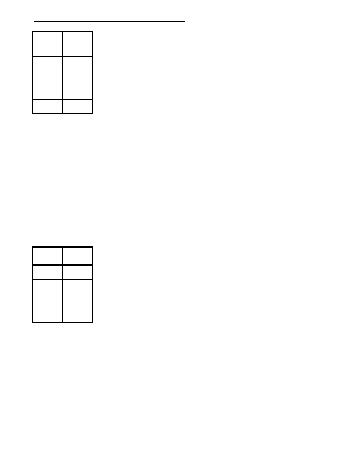
Program 39 - Common Unrestricted Codes
(Display sh ows: COMM.UNRESTRICT)
Common
Unrestricted
Code #
1
2
3
4
Program Record Form Entry
1. For each Common Unrestricted Code number, assign an access code digit (4 digits maximum).
System Program Entry
1. Ent er 39 (program nu mber).
2. Press *.
3. Ent er the Common Unrestricted Cod e number (1-4) to be programmed.
4. Press *.
5. Enter the value for the code being programmed.
6. Press *.
7. Enter the value for the next Common Unrestricted Code OR
Press * to skip to the next code OR
Press # to exit the program.
Common
Unrestricted
Codes
Options
Common Unrestricted Codes Digits:
Digits 0-9 are accepted
Program 40 - COS 1, Restricted Codes
Restricted
Code #
1
2
3
4
Program Record Form Entry
1. For each Restricted Code number, assign a Restricted Code digit (4 digits maximum).
System Program Entry
1. Ent er 40 (program nu mber).
2. Press *.
3. Ent er the Restri cted Code number (1-4) to be programmed.
4. Press *.
5. Enter the value for the code being programmed.
6. Press *.
7. Enter the value for the next Restricted Code OR
Press * to skip to the next code OR
Press # to exit the program.
Restricted
Code
(Display sh ows: RESTR.CODES B)
Options
Restricted Codes Digits:
Digits 0-9 are accepted
- 28 -
Page 37
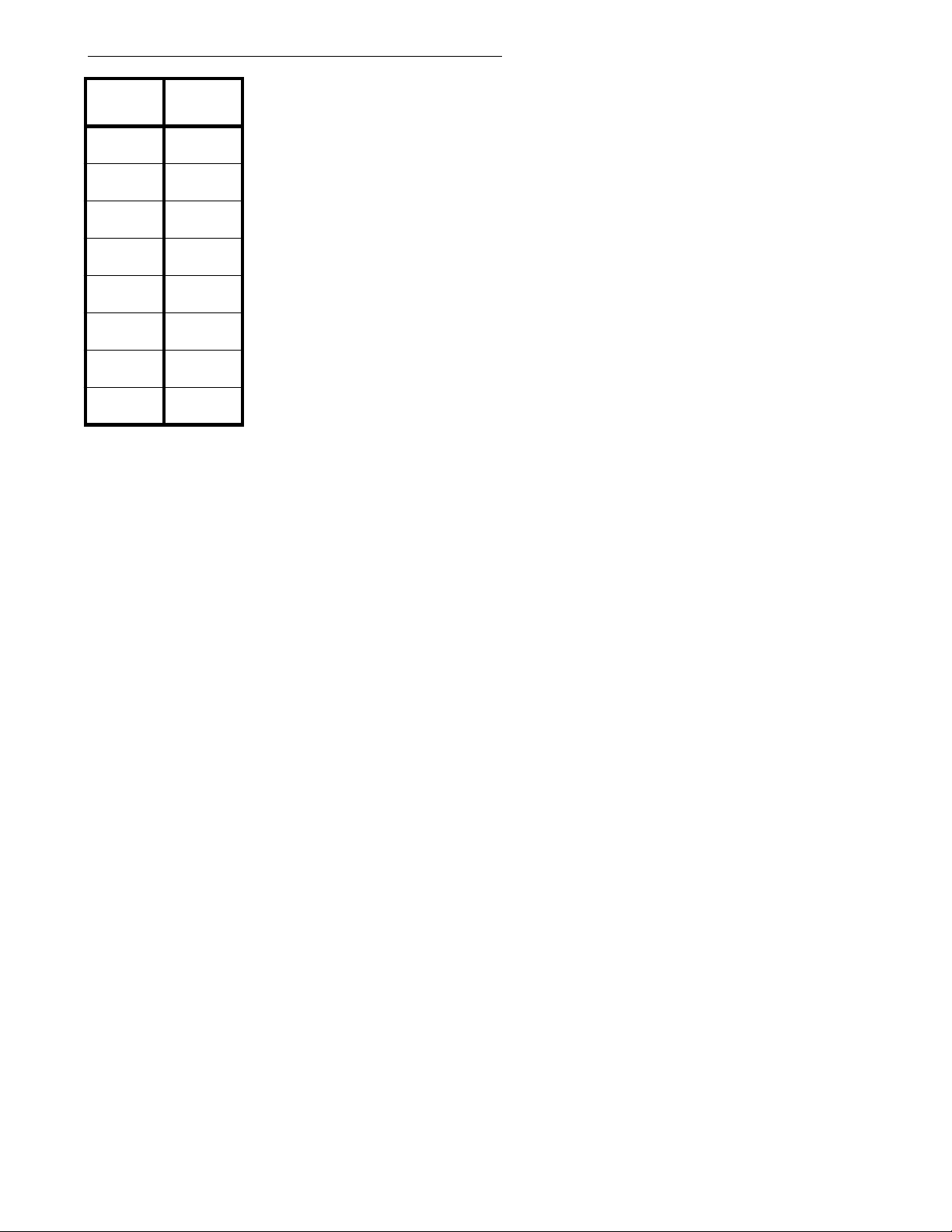
Program 41 - COS 2 and 3, Restricted Codes
(Display shows: RESTR. CODES D2)
Restricted
Code #
1
2
3
4
5
6
7
8
Program Record Form Entry
1. For each Restricted Code number, enter the digits to be assigned to the code number (2 digits maximum).
System Program Entry
1. Ent er 41 (program nu mber).
2. Press *.
3. Ent er the Restri cted Code number (1-8) to be programmed.
4. Press *.
5. Enter the value for the code being programmed.
6. Press *.
7. Enter the value for the next Restricted Code OR
Press * to skip to the next code OR
Press # to exit the program.
Restricted
Code
Options
Restricted Codes Digits:
Digits 0-9 are accepted
- 29 -
Page 38
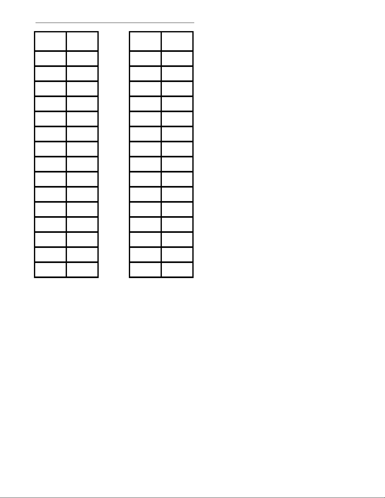
Program 42 - Walking COS Security Code
(Display shows: UNREST.SEC.CODES)
Security
Code #
01 16
02 17
03 18
04 19
05 20
06 21
07 22
08 23
09 24
10 25
11 26
Security
Code
Security
Code #
Security
Code
Options
Restricted Codes Digits:
Digits 0-9 are accepted
12 27
13 28
14 29
15 30
Program Record Form Entry
1. For each Security Code number, enter the digits to be assigned to the code
System Program Entry
1. Ent er 42 (program nu mber).
2. Press *.
3. Ent er the Securi ty Cod e number (01-30) to be programmed.
4. Press *.
5. Enter the value for the code being programmed.
6. Press *.
7. Enter the value for the next Security Code OR
Press * to skip to the next code OR
Press # to exit the program.
- 30 -
Page 39
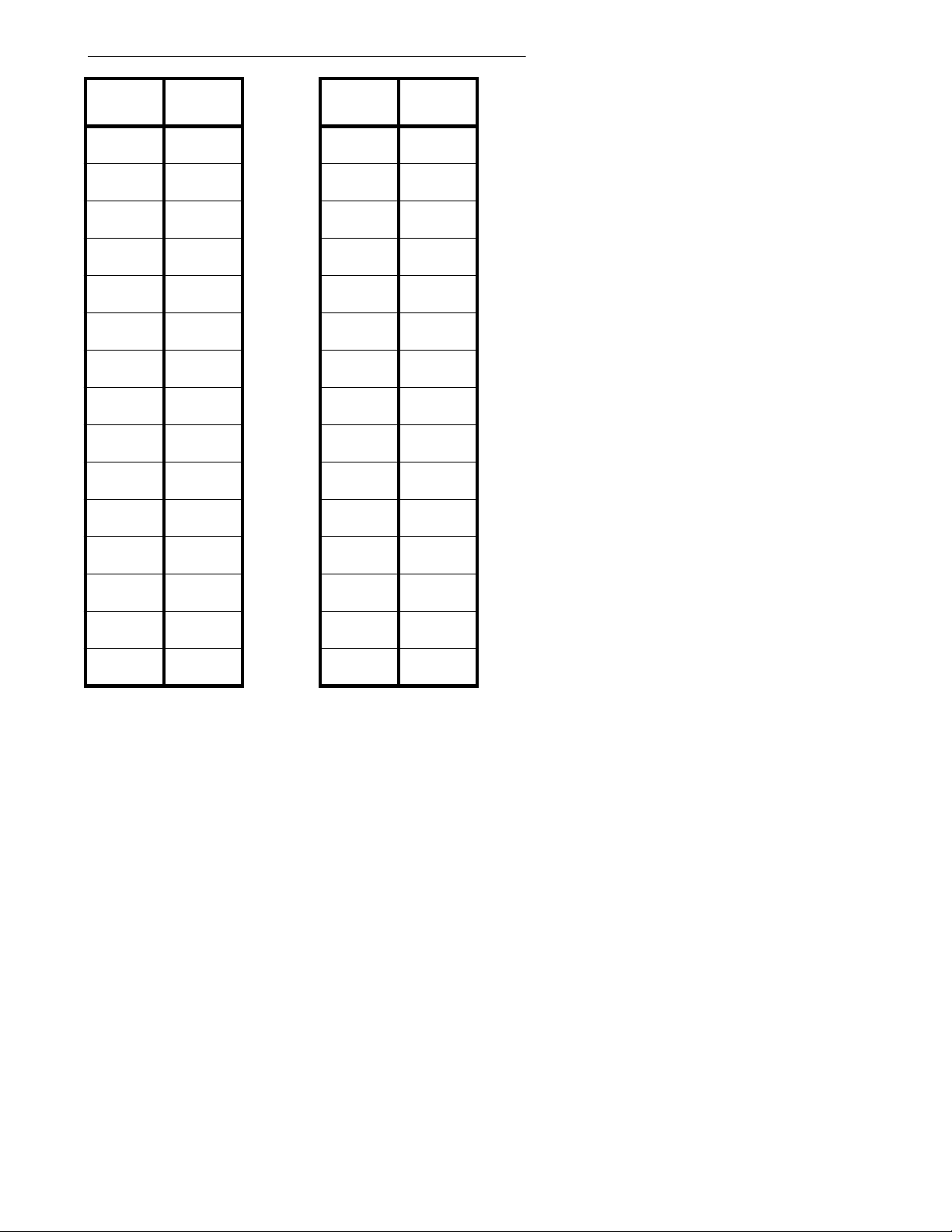
Program 43-COS Assignment on Security Code
(Display shows: UNREST.CLASS)
Security
Code #
01 16
02 17
03 18
04 19
05 20
06 21
07 22
08 23
09 24
10 25
11 26
Class of
Service
Security
Code #
Class of
Service
Options
Enter one of the following Class of Service levels for
each Security Code:
0 = No Restrictions
1 = Restricted by Program 40 [4 codes, 4 digits long].
Allows calls matching PBX extension and
Common Unrestricted Codes (Program 39).
2 = Restricted by Program 41 [8 codes, 4 digits long].
Allows Permitted Codes (Program 36), PBX
extension calls and Common Unrestricted
Codes (Program 39).
3 = Restricted by Program 37 and Program 41
[8 codes, 2 digits long]
Allows PBX extension calls and Common
Unrestricted Codes (Program 39).
4 = Restricts all outgoing calls.
Allows PBX extension calls and Common
Unrestricted Codes (Program 39).
5 = Restricted to Intercom calls only.
12 27
13 28
14 29
15 30
Program Record Form Entry
1. For each Walking Class Security Code number,
enter a Class of Service to be assigned to the code.
System Program Entry
1. Ent er 43 (program nu mber).
2. Press *.
3. Ent er the Securi ty Cod e number (01-30) to be programmed.
4. Press *.
5. Enter the Class of Service for the code being programmed.
6. Press *.
7. Enter the value for the next Security Code OR
Press * to skip to the next code OR
Press # to exit the program.
- 31 -
Page 40
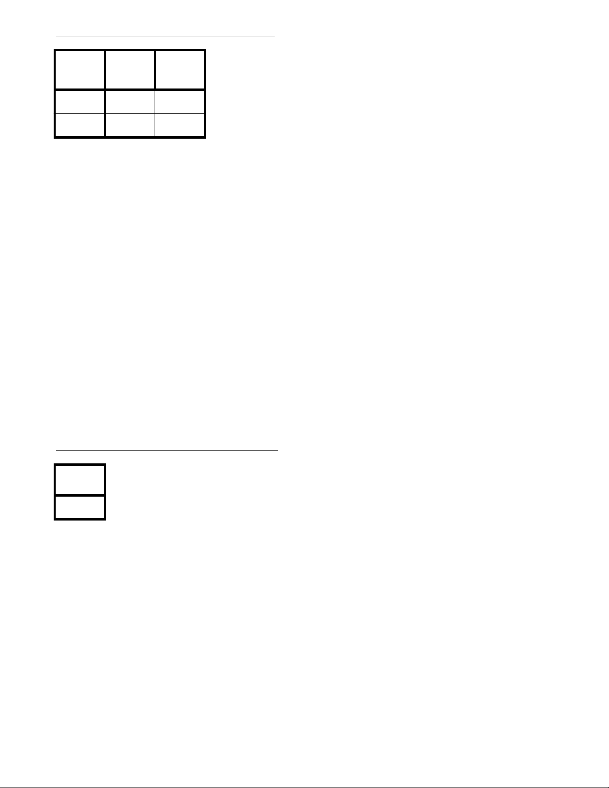
Program 44 - External Alarm Sensor
(Display shows: ALARM SENSOR)
Alarm #
1
2
Program Record Form Entry
1. Enter desired option number in each feature's column.
System Program Entry
1. Ent er 44 (program nu mber).
2. Press *.
3. Ent er the alarm number to be programmed.
4. Press *.
5. Enter the value from column A for the alarm being programmed.
6. Press *.
7. Enter the value from column B for the alarm being programmed.
8. Press *.
9. If the first alarm programmed was '1', yo u can en ter alarm '2'
information by repeating steps 5-8 OR
Press # to exit the program.
(A.) Alarm
Installed?
(B.) Alarm
Trigger
Condition
Options
(A.) Alarm Installed?
0=not installed, 1=installed
(B.) Alarm Trigger Condition
Internal Power: 0=normally closed
loop, 1=normally open loop
OR
External Power: 0=normally open
loop, 1=normally closed loop
Program 45 - Intercom Link Increase
Last Used
Line #
Program Record Form Entry WARNING:
1. Enter the last line number used in the system. The system will reset upon exiting
System Program Entry
1. Ent er 45 (program nu mber).
2. Press *.
3. Enter the last line number used in the system.
4. Press *.
5. Press # to exit the program.
(Display sh ows: ICM LINK INCR.)
Options
Last Used Line #:
00 = not assigned, 01-24 = last line
number used
programming mode if this program
is changed.
- 32 -
Page 41
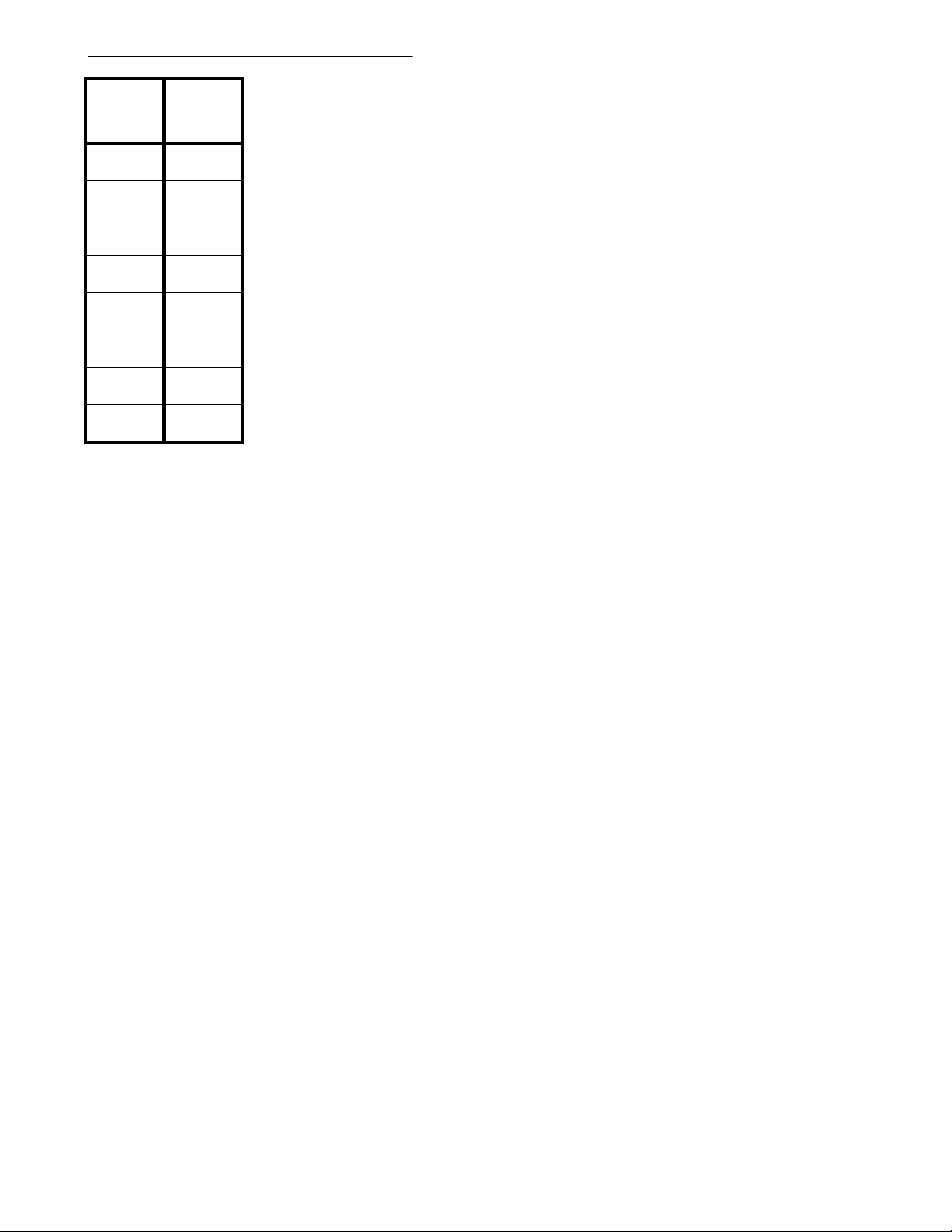
Program 46 - DISA Security Codes
(Display shows: DISA SEC.CODES)
DISA
Security
Code #
1
2
3
4
5
6
7
8
Program Record Form Entry
1. For each DISA Security Code number, enter the digits to be assigned
to the code number (4 digits maximum).
Security
Code
Options
Security Code Digits:
Digits 0-9 are accepted
System Program Entry
1. Ent er 46 (program nu mber).
2. Press *.
3. Enter the DISA Security C ode number (1-8) to be programmed.
4. Press *.
5. Enter the value for the code being programmed.
6. Press *.
7. Enter the value for the next DISA Security Code OR
Press * to skip to the next code OR
Press # to exit the program.
- 33 -
Page 42
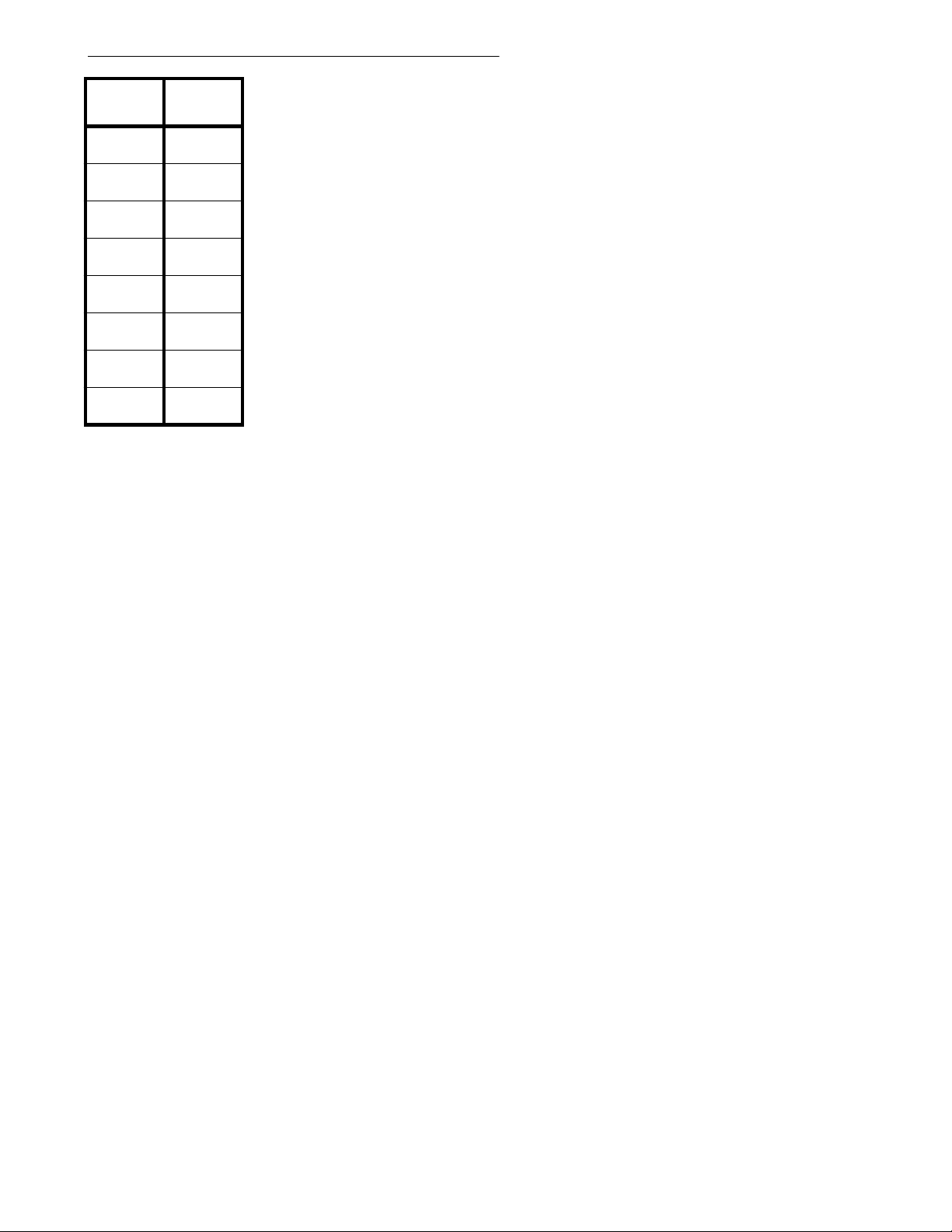
Program 47 - DISA Sec urity Code Extension
(Display shows: DISA SEC.CODE ST)
Security
Code #
1
2
3
4
5
6
7
8
Program Record Form Entry
1. For each DISA Security Code number, enter the extension port number
to be assigned to the code.
System Program Entry
1. Ent er 47 (program nu mber).
2. Press *.
3. Enter the DISA Security C ode number (1-8) to be programmed.
4. Press *.
5. Enter the extension port for the code being programmed.
6. Press *.
7. Enter the extension port for the next DISA Security Code OR
Press * to skip to the next code OR
Press # to exit the program.
Extension
Port #
- 34 -
Page 43
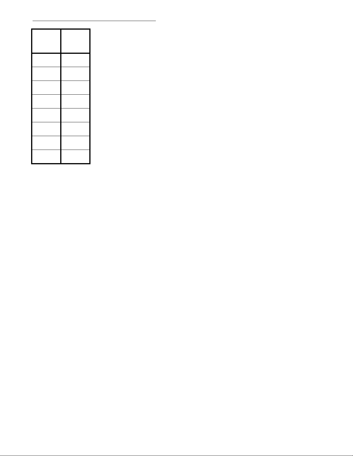
Program 48 - DISA Class of Service
(Display shows: DISA COS)
DISA
Security
Code #
1
2
3
4
5
6
7
8
Program Record Form Entry
1. For each DISA Security Code number, enter a
Class of Service to be assigned to the code.
Class of
Service
Options
Enter one of the following Class of Service levels for each
Security Code:
0 = No Restrictions
1 = Restricted by Program 40 [4 codes,4 digits long].
Allows calls matching PBX extension and
Common Unrestricted Codes (Program 39).
2 = Restricted by Program 41 [8 codes, 4 digits long].
Allows Permitted Codes (Program 36), PBX
extension calls and Common Unrestricted
Codes (Program 39).
3 = Restricted by Program 37 and Program 41 [8 codes,
2 digits long].
Allows PBX extension calls and Common
Unrestricted Codes (Program 39).
4 = Restricts all outgoing calls.
Allows PBX extension calls and Common
Unrestricted Codes (Program 39).
5 = Restricted to Intercom calls only.
System Program Entry
1. Ent er 48 (program nu mber).
2. Press *.
3. Enter the DISA Security C ode number (1-8) to be programmed.
4. Press *.
5. Enter the Class of Service for the code being programmed.
6. Press *.
7. Enter the value for the next DISA Security Code OR
Press * to skip to the next code OR
Press # to exit the program.
- 35 -
Page 44
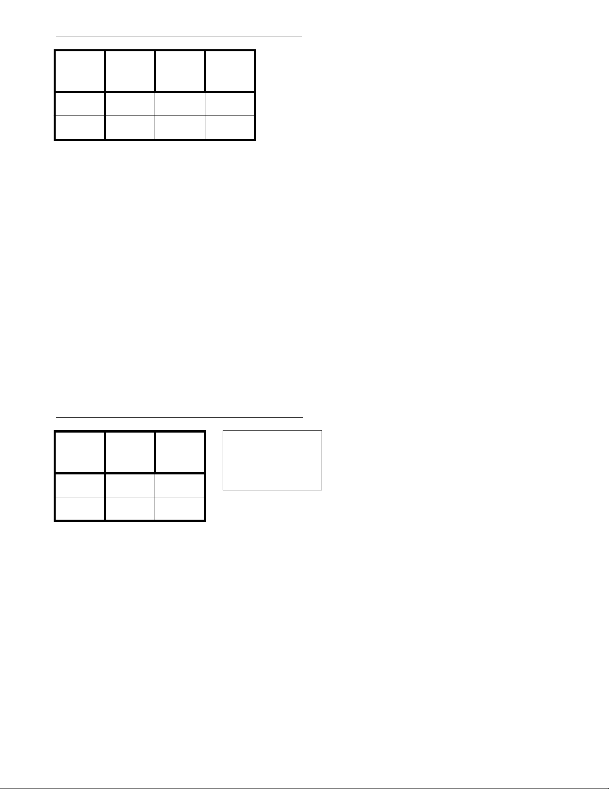
Program 49 - External Zone BGM/Alarm
(Display shows: EXT.ZONE BGM/ALM)
External
Speaker
Zone
1
2
Program Record Form Entry
1. Enter desired option number in each feature's column.
System Program Entry
1. Ent er 49 (program nu mber).
2. Press *.
3. Enter the external speaker zone number (1 or 2) to be programmed.
4. Press *.
5. Enter the value from columns A-C.
6. Press *.
7. If the first external speaker zone programmed was '1', you can enter the
information for zone '2' by repeating steps 5-6 OR
Press # to exit the program.
(A.)
Background
Music
(B.) Alarm#1(C.) Alarm
#2
Options
(A.) Background Music
(Not us ed with Portrait 308)
0=dis abled, 1=enabled
(B.) Alarm #1
0=dis abled, 1=enabled
(C.) Alarm #2
(Not us ed with Portrait 308)
0=dis abled, 1=enabled
Program 50 - External Zone Line Audible
External
Speaker
Zone
1
2
Program Record Form Entry
1. Enter desired option number in each feature's column.
System Program Entry
1. Ent er 50 (program nu mber).
2. Press *.
3. Enter the external speaker zone number (1 or 2) to be programmed.
4. Press *.
5. Enter the value from columns A-B.
6. Press *.
7. If the first external speaker zone programmed was '1', you can enter the
information for zone '2' by repeating steps 5-6 OR
Press # to exit the program.
(A.) Line
Group
(B.)
Incoming
Ring Mode
Note: The Portr ait
308 only has one
external speaker
zone.
(Display shows: EXT.ZONE LN/AUD)
Options
(A.) Line Group
00=no ringing, 01-30=Group 01 Group 30
(B.) Incoming Ring Mode
0=no ringing, 1=day ring,
2=night ring, 3=day and
night ring
- 36 -
Page 45
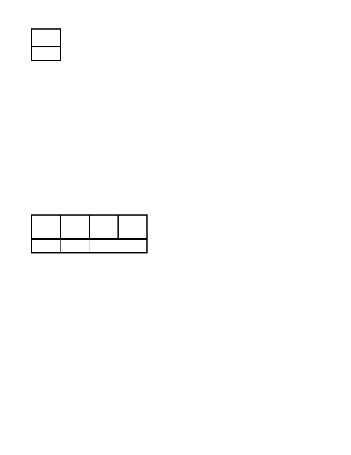
Program 51 - Attendant Extension for DISA
(Display shows: A.A. DIVERT STA.)
Attendant
Ext. Port #
Program Record Form Entry
1. Enter the attendant's extension port number for DISA.
System Program Entry
1. Ent er 51 (program nu mber).
2. Press *.
3. Enter the attendant's extension port number.
4. Press *.
5. Press # to exit the program.
Options
Attendant Extension Port
Number for DISA:
10-33 = extensi on port number
Program 52 - Tenant Options
(1.)
Intercom
Call
Program Record Form Entry
1. Enter desired option number in each feature's column.
System Program Entry
1. Ent er 52 (program nu mber).
2. Press *.
3. Enter the option number (1-4) to be programmed.
4. Press *.
5. Enter the value for the option being programmed.
6. Press *.
7. Enter the value for the next option OR
Press * to skip the displayed option OR
Press # to exit the program.
(2.) Internal
Paging
(3.)
Common
Speed Dial
(4.) Transfer
to Attendant
(Display shows: TENANT OPTION)
Options
(1.) Intercom Call
0=ena bled, 1=disabled
(2.) Internal Paging
0=ena bled, 1=disabled
(3.) Common Speed Dial
0=common use, 1=assigned
Speed Dial
(4.) Transfer to Attendant
0=system, 1=each tenant
group
- 37 -
Page 46
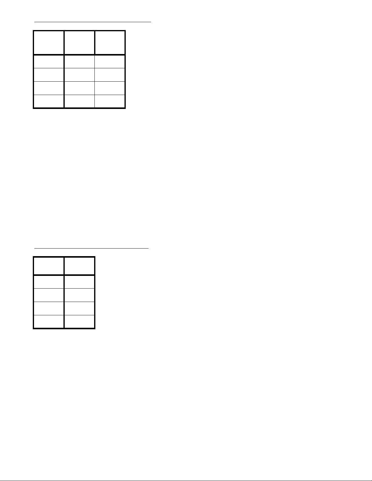
Program 53 - Tenant Speed Dial
(Display shows: TENANT ABBR.DIAL.)
Tenant
Group #
01
02
03
04
Program Record Form Entry
1. Enter the first and last speed dial numbers each tenant group will be able to access.
System Program Entry
1. Ent er 53 (program nu mber).
2. Press *.
3. Enter the tenant group (01-04) to be programmed.
4. Press *.
5. Enter the value from column A.
6. Press *.
7. Enter the value from column B.
8. Press *.
9. Enter the information for the next tenant group OR
Press ** to skip the displayed tenant group OR
Press # to exit the program.
(A.) First
Speed
Dial #
(B.) Last
Speed
Dial #
Options
(A.) First Speed Dial #
00-99=available speed dial
numbers
(B.) Last Speed Dial #
00-99=available speed dial
numbers
Program 54 - Tenant Attendant
Tenant
Group #
01
02
03
04
Program Record Form Entry
1. Enter the attendant's extension port number for each Tenant Group.
System Program Entry
1. Ent er 54 (program nu mber).
2. Press *.
3. Enter the attendant's extension port number for the display Tenant Group OR
Press * to skip to the next Tenant Group.
4. Press *.
5. Enter the information for the next Tenant Group OR
Press * to skip the display Tenant Group OR
Press # to exit the program.
Attendant
Ext. Port #
(Display shows: TENANT ATT.ASSIG)
Options
Attendant Extension Port Number
for each Tenant Group:
10-33 = extensi on port number
- 38 -
Page 47
Program 55 - Park Key Assignment
(Display shows: PARK HD LN.ASSIG)
Park Group#(A.) First
Park Key #
01
02
03
04
Program Record Form Entry
1. Enter the first and last Park Key numbers each Park Group will be able to use.
System Program Entry
1. Ent er 55 (program nu mber).
2. Press *.
3. Ent er the Park Group (01-04) to be programmed.
4. Press *.
5. Enter the value from column A.
6. Press *.
7. Enter the value from column B.
8. Press *.
9. Enter the information for the next Park Group OR
Press ** to skip the displayed Park Group OR
Press # to exit the program.
(B.) Last
Park Key #
Note: These
options are not
available wi th the
Portrait 308.
Options
(A.) First Park Key #
00=not assigned,
01-12=line key number
(B.) Last Park Key #
00=not assigned,
01-12=line key number
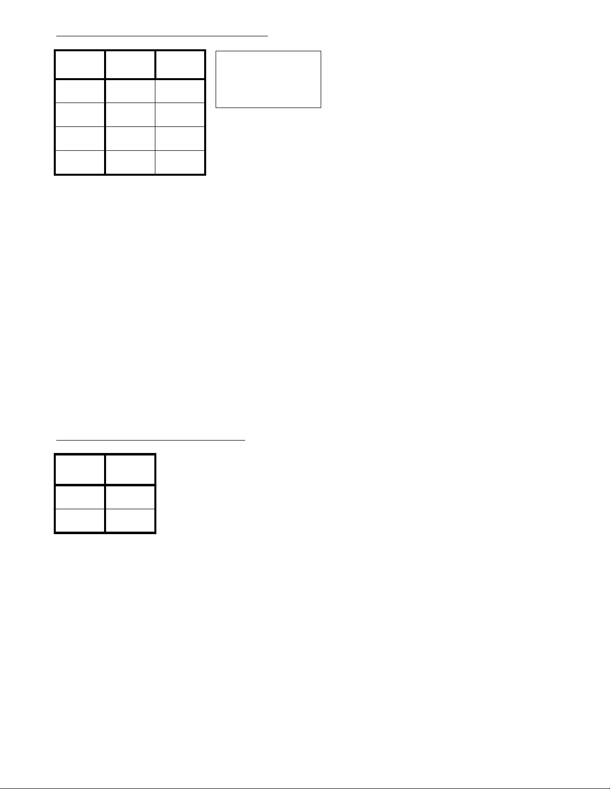
Program 56 - Relay Assignment
Relay #
1
2
Program Record Form Entry
1. Enter the option to be assigned to each relay.
System Program Entry
1. Ent er 56 (program nu mber).
2. Press *.
3. Ent er the relay number (1-2) to be programmed.
4. Press *.
5. Enter the value from column A.
6. Press *.
7. Enter the information for the next relay OR
Press # to exit the program.
(A.) Relay
Option #
(Display shows: RELAY ASSIGN)
Options
(A.) Relay Option
0=not assigned, 1=Door Box 1,
2=Door Box 2, 3=external MOH,
4=Background Music
(Background Music is only
avai lable on the Portrait 824. )
- 39 -
Page 48
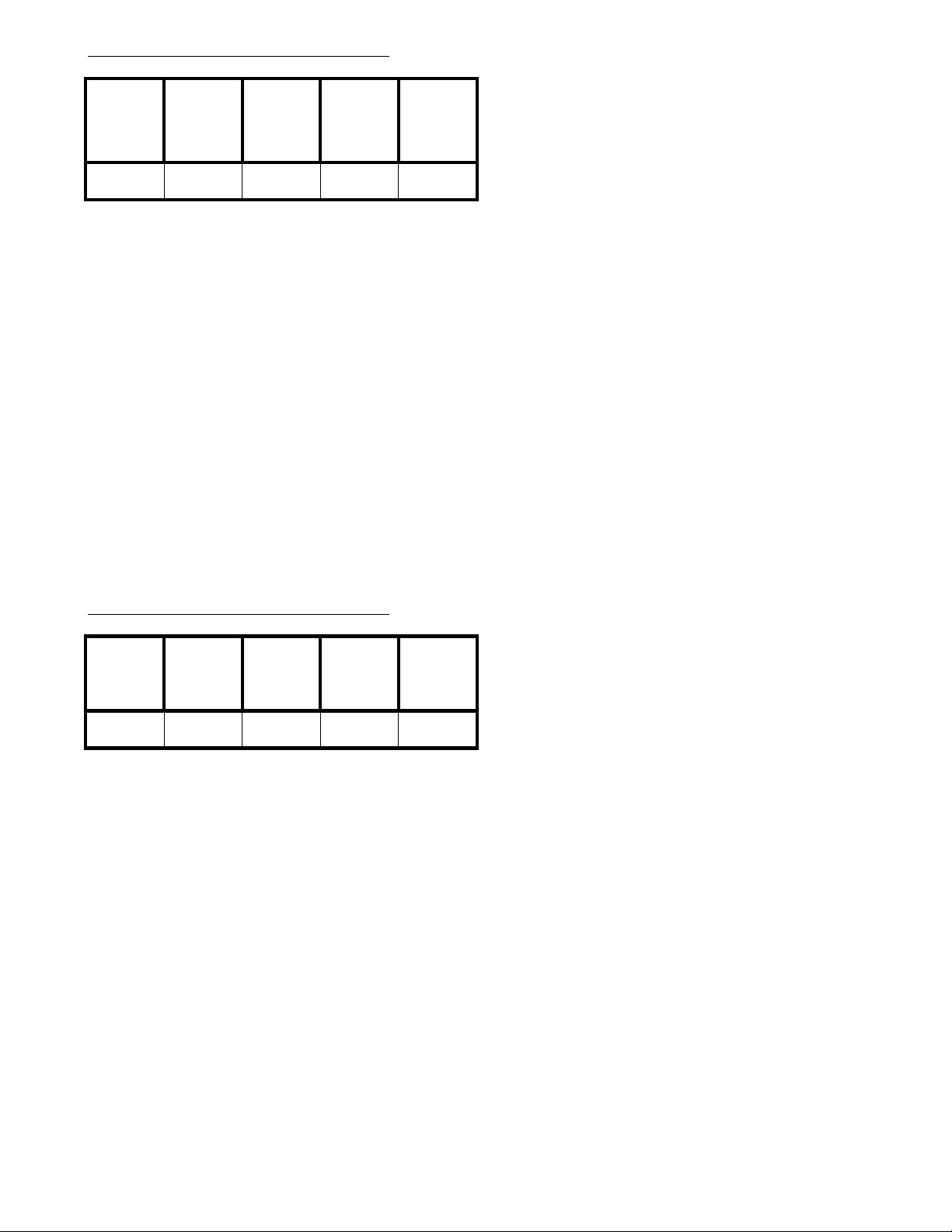
Program 57 - SMD R Options (1)
(Display shows: SMDR ASSIGNMENT1)
(B.)
(A.) Dial
Digits
Program Record Form Entry
1. Enter desired option number in each feature's column.
System Program Entry
1. Ent er 57 (program nu mber).
2. Press *.
3. Enter data from columns A-E.
4. Press *.
5. Press # to exit program.
Outgoing/
Incoming
Transfer
(C.) No
Answer
(D.) KTS
Account
Code
Incoming
(E.)
Call
Options
(A.) Dial Digits
0=every time, 1=more than the number of dig its
assigned in Program 59
(B.) Outgoing/Incoming Transfer
0=printed, 1=not printed
(C.) No Answer
0=printed, 1=not printed
(D.) KTS Account Code
0=input enabled, 1=input forced before dial,
2=input disabled
(E.) Incoming Call
0=printed every time, 1=printed when account
code is entered
Program 58 - SMD R Options (2)
(A.) Print
Barred
Outoing
Calls
Program Record Form Entry
1. Enter desired option number in each feature's column.
System Program Entry
1. Ent er 58 (program nu mber).
2. Press *.
3. Enter data from columns A-E.
4. Press *.
5. Press # to exit program.
(B.) Allow
SLT
Account
Code
(C.) Print
Dialed
Number
(D.) Caller
I.D.
Printout
(Display shows: SMDR ASSIGNMENT2)
Masking
(E.)
Digit
Options
(A.) Print Barred Outgoing Calls
0=printed, 1=not printed
(B.) Allow SLT Account Code
0=input enabled, 1=input disabled
(C.) Print Dialed Number
0=printed, 1=not printed
(D.) Caller I.D. Printout
0=not printed, 1= telephone number printed,
3= name printed if programed,
otherwise telephone number printed.
(E.) Masking digit
0=dis abled, 1-9= # of digits from the end
of the # to be masked (replaced
by an ' x').
- 40 -
Page 49
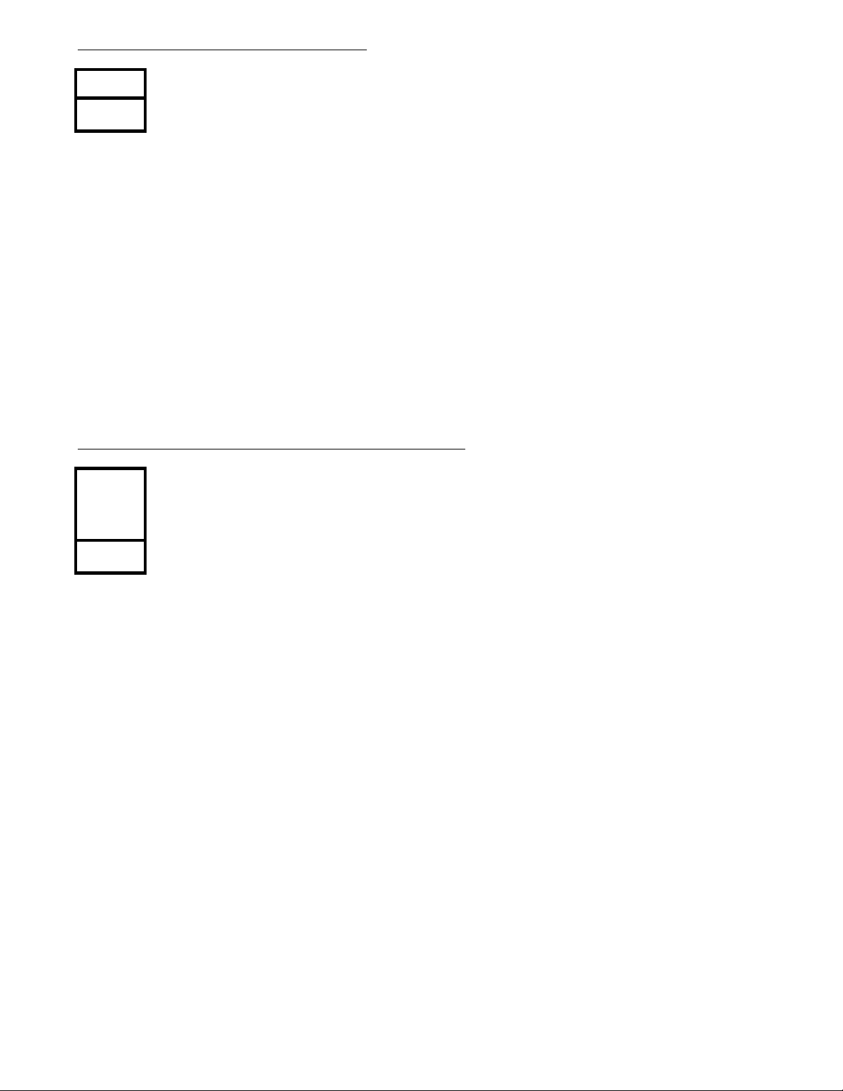
Program 59 - SMD R Printout Digit
Dial Digits
Program Record Form Entry
1. Enter the number of dialed digits (01-24) that must be exceeded
in order for the SMDR to print the call.
System Program Entry
1. Ent er 59 (program nu mber).
2. Press *.
3. Enter the number of dialed digits to be exceeded for SMDR printout.
4. Press *.
5. Press # to exit the program.
(Display shows : SMDR PRINT DIGIT)
Program 60 - Loop Disconnect Detection Timer
Loop
Disconnect
Detection
Timer
Program Record Form Entry
1. Enter the time the system should wait for detecting open loop (disconnect) from telco.
System Program Entry
1. Ent er 60 (program nu mber).
2. Press *.
3. Enter the value for the timer.
4. Press *.
5. Press # to exit the program.
Options
Loop Disconnect Detection Timer:
000=not detected, 001 - 050=20-1000 ms
(20 ms steps)
(Display shows: LOOP DISCONNECT)
- 41 -
Page 50
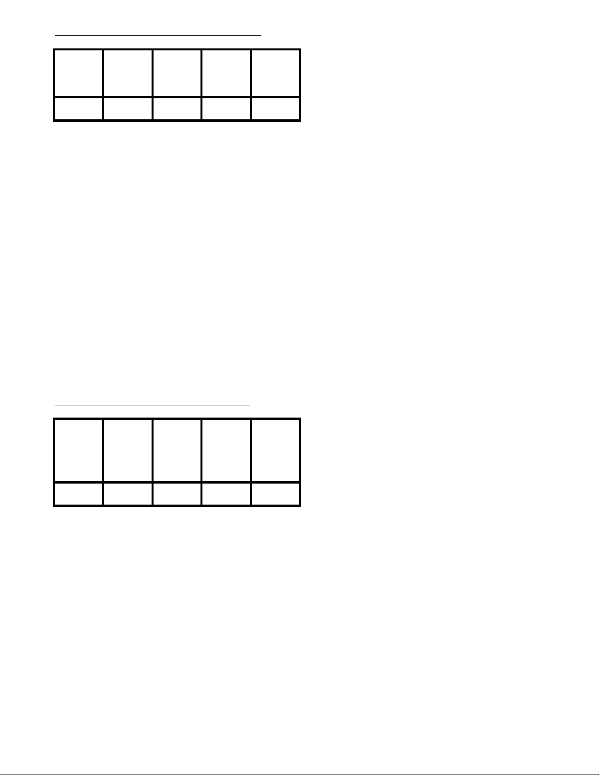
Program 61 - Extension Options (4)
(Display shows: STN ASSIGNMENT4)
(A.)
Message
Edit Mode
Program Record Form Entry
1. Enter desired option number in each feature's column.
System Program Entry
1. Ent er 61 (program nu mber).
2. Press *.
3. Enter extension port number.
4. Press *.
5. Enter data from columns A-E.
6. Press *.
7. The next extension port displays. Repeat steps 5-6 OR
Press * to advance to another extension OR Press # to exit the program.
(B.) Caller
ID
Indication
(C.) Edit
Caller ID
Table
(D.) SMDR
Prints
Outgoing
Information
(E.) Door
Box
Restricted
Options
(A.) Message Edit Mode
0=phone's dial pad '1' key has Q_Z printed
above it, 1=phone's dial pad '1' key has no
letters indicated
(B.) Caller ID Indication
0=not displayed, 1=displayed
(C.) Edit Caller ID Table
0=dis abled, 1=enabled
(D.) SMDR Prints Outgoing Information
0=printed out, 1=not printed out
(E.) Door Box Restricted
0=ena bled, 1=disabled
Program 64 - System Options (7)
(B.)
(A.) Not
Used
0
Program Record Form Entry
1. Enterdesired option number in each feature's column.
System Program Entry
1. Ent er 64 (program nu mber).
2. Press *.
3. Enter data from columns A-E.
4. Press *.
5. Press # to exit the program.
Temporary
Memory
Status
(C.)
Automatic
Line Access
With Single
Digit Code
(D.) LED
Indication
for Incoming
DISA Call
(E.) SLT
Operation
Flash
(Display shows: SYS ASSIGNMENT7)
Options
(A.) Not Used
Must be entered as "0"
(B.) Temporary Memory Status
0=not displayed, 1=displayed
(C.) Automatic Line Access With Single Digit
Code
0=lowest line number available, 1=highest line
number available, 2=rotating lines (line 1, then
line 2, then line 3, etc.)
(D.) LED Indication for Incoming DISA Call
0=incoming DISA calls show busy LED,
1=incoming DISA calls flash like an incomin g call
(E.) SLT Flash Operation
0=ena bled, 1=disabled
- 42 -
Page 51
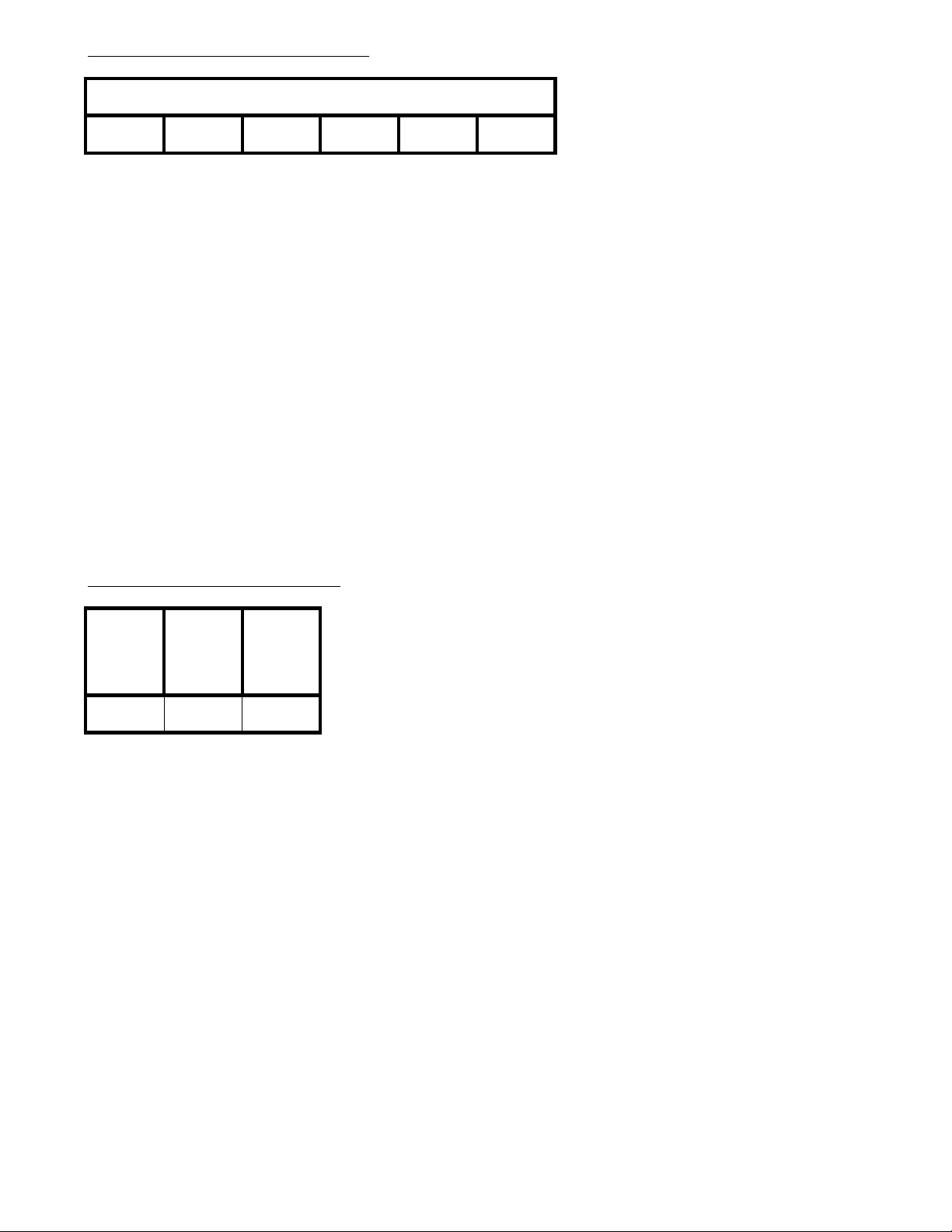
Program 65 - Voice Mail Port
(Display shows: VOICE MAIL PORT)
Voice Mail Port(s)
Program Record Form Entry
1. Enter the port number(s) to be assigned to the voice mail.
System Program Entry
1. Ent er 65 (program nu mber).
2. Press *.
3. Enter the port to be assigned to the voice mail.
4. Press *.
5. Enter the next port to be assigned OR Press # to exit the program.
Options
For each voice mail port, assign the
extension port number to be used
00=no port assigned, 10 - 17 (308),
10 - 33 (824)=extensi on ports
Program 66 - DISA T imer s
(1.)
Automatic
Answer
Time
Program Record Form Entry
1. Enter desired option number in each feature's column.
System Program Entry
1. Ent er 66 (program nu mber).
2. Press *.
3. Enter the option number (1-3) to be programmed.
4. Press *.
5. Enter data for the option being programmed.
6. Press *.
7. Enter the information for the next displayed option OR
Press # to exit program.
(2.) Dial
Waiting
Time
(3.)
Extension
Calling
Time
(Display shows: DISA TIMERS)
Options
(1.) Automatic Answer Time
000=answers at on ce, 001-255 =
1-255 seconds
(2.) Dial Waiting Time
001-255 = 1-255 seconds
(3.) Extension Calling Time
001-255 = 1-255 seconds
- 43 -
Page 52
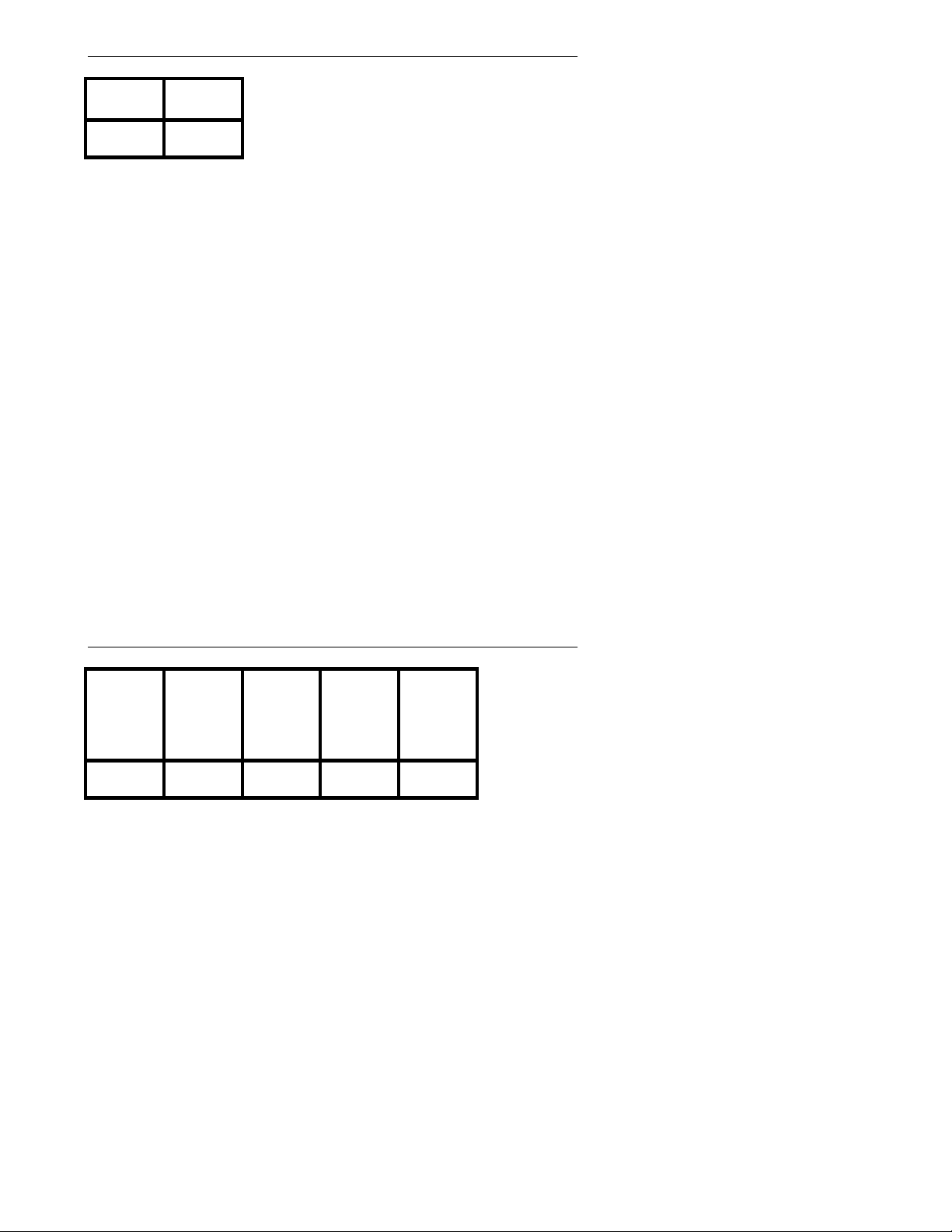
Program 67 - Fax Assignment (1) (Portrait 308 Only)
(Display shows: FAX ASSIGNMENT1)
(1.) Line
Number
Program Record Form Entry
1. Enter the line number and station port to be assigned to the
fax machine.
System Program Entry
1. Ent er 67 (program nu mber).
2. Press *.
3. Enter the line number to be assigned.
4. Press *.
5. Enter the station port to be assigned.
6. Press *.
7. Press # to exit the program.
(2.) Station
Port
Options
(1.) Line Number
00=not assigned, 01 - 03=line n umbers 01-03
(2.) Stati on Port
00=not assigned, 12 - 17=stations 12-17
Program 68 - Fax Assignment (2) (Portrait 308 Only)
(B.) CNG
(A.) Line
Type
Program Record Form Entry
1. Enter the desired option number in each feature's column.
System Program Entry
1. Ent er 68 (program nu mber).
2. Press *.
3. Enter the data from columns A-E.
4. Press *.
5. Press # to exit the program.
Signal is
Not
Received
(C.)
Extension
Busy
(D.) Not
Used
00
(E.) Not
Used
Options
(A.) Line Type
0=fax, 1=DISA, 2=fax and DISA
(B.) CNG Signal is Not Received
0=cut off, 1=transfer to operator, 2=transfer
to fax
(C.) Extension Busy
0=cut off, 1=transfer to operator, 2=resend
Attendant Message #2
(D.) Not Us ed
Must be entered as "0".
(E.) Not Used
Must be entered as "0".
(Display shows: FAX ASSIGNMENT2)
- 44 -
Page 53
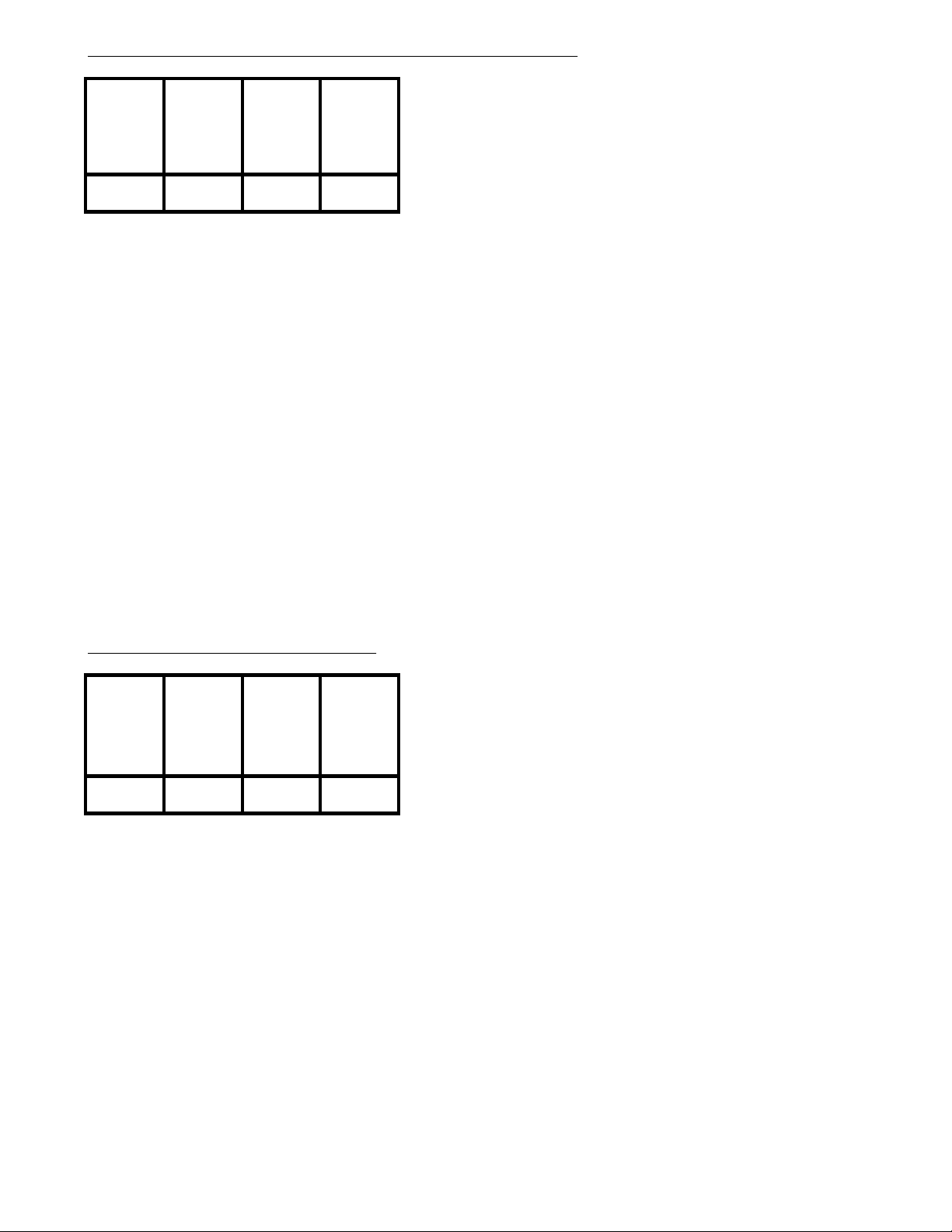
Program 69 - Fax Assignment (3) (Portrait 308 Only)
(Display shows: FAX ASSIGNMENT3)
(1.)
Automatic
Answer
Program Record Form Entry
1. Enter the desired option number in each feature's column.
System Program Entry
1. Ent er 69 (program nu mber).
2. Press *.
3. Enter the data from column 1 OR Press * to advance to the
desired option, then enter data.
4. Press *.
5. Enter the data for the next option or press * to advance to the desired option.
6. Press # to exit the program.
(2.) Waiting
Time for
CNG Signal
Detection
(3.) Waiting
Time for
DTMF
Signal
Receiving
(4.) Calling
Time for
Telephone /
Fax
Options
(1.) Automatic Answer
000=im mediate answer, 001 - 255=1-255
seconds
(2.) Waiting Time for CNG Signal Dectection
000=not assigned, 001 - 255=1-255 seconds
(3.) Waiting Time for DTMF Signal Receiving
000=not assigned, 001 - 255=1-255 seconds
(4.) Calling Time for Telephone/Fax
000=not assigned, 001 - 255=1-255 seconds
Program 74 - Caller ID Timers
(1.) Caller
ID
Information
Waiting
Timer
Program Record Form Entry
1. Enter the desired option number in each feature's column.
System Program Entry
1. Ent er 74 (program nu mber).
2. Press *.
3. Enter the item number to be programmed.
4. Press *.
5. Enter the data for the option being programmed.
6. Press *.
7. Enter the data for the next option OR Press # to exit the program.
(2.)
Incoming
Signal
Detection
Timer
(3.) Caller
ID Signal
Duration
Timer
(4.) Caller
ID Signal
Carrier
Detection
Timer
(Display shows: CALLER-ID TIMERS)
Options
(1.) Caller ID Information Waiting Timer
000=no delay, 001 - 015=1-15 seconds
(2.) Incoming Signal Detection Timer
000 - 015=0-1.5 seconds (in 100 ms intervals)
(3.) Caller ID Signal Duration Timer
000 - 015=0-750 ms (in 50 ms intervals)
(4.) Caller ID Signal Carrier Detection Timer
000 - 008=500-900 ms (50 ms intervals) OR
009 - 014=1-2 seconds (200 ms intervals )
OR 015=3 sec onds. Example: 000=500 ms,
001=500 ms, 002=600 ms, etc . OR 009=1.0
second, 010=1.2 seconds, 011=1.4 seconds
OR 015=3 seconds
- 45 -
Page 54
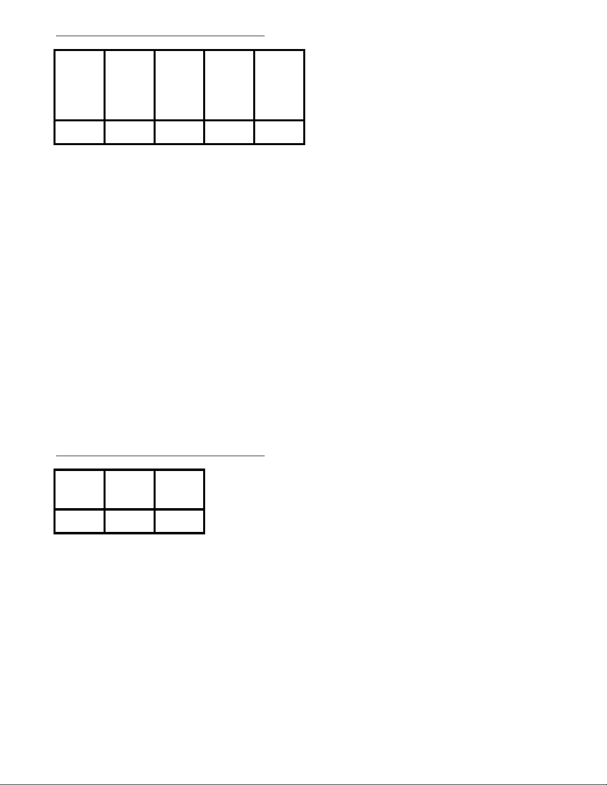
Program 75 - Extension Options (5)
(Display shows: STN ASSIGNMENT5)
(C.)
(A.) Not
Used
00 00
Program Record Form Entry
1. Enter the desired option number in each feature's column.
System Program Entry
1. Ent er 75 (program nu mber).
2. Press *.
3. Enter the station port to be programmed.
4. Enter the data from columns A-E.
5. Press *.
6. Enter the data for the next station OR Press * to advance the
station port numbers OR Press # to exit the program.
(B.) Not
Used
Automatic
Line Seizing
by Fax
(D.) Not
Used
(E.) Not
Used
Options
(A.) Not Used
Must be entered as "0".
(B.) Not Used
Must be entered as "0".
(C.) Automatic Line Seizing by Fax
0=dis abled, 1=enabled
(D.) Not Us ed
Must be entered as "0".
(E.) Not Used
Must be entered as "0".
Program 77 - Extension Options (6)
(A.) Hold in
Day Mode
Program Record Form Entry
1. Enter the desired option number in each feature's column.
System Program Entry
1. Ent er 77 (program nu mber).
2. Press *.
3. Enter the station port to be programmed.
4. Enter the data from columns A-C.
5. Press *.
6. Enter the data for the next station OR Press * to advance the
station port numbers OR Press # to exit the program.
(B.) Hold in
Night Mode
(C.) Hold in
Dial B lock
Mode
(Display shows: STN ASSIGNMENT6)
Options
(A.) Day Mode
0=Hold feature subject to Program 87,
1=can always place calls on Hold
immediately
(B.) Night Mode
0=Hold feature subject to Program 87,
1=can always place calls on Hold
immediately
(C.) Dial Block Mode
0=Hold feature subject to Program 87,
1=can always place calls on Hold
immediately.
- 46 -
Page 55
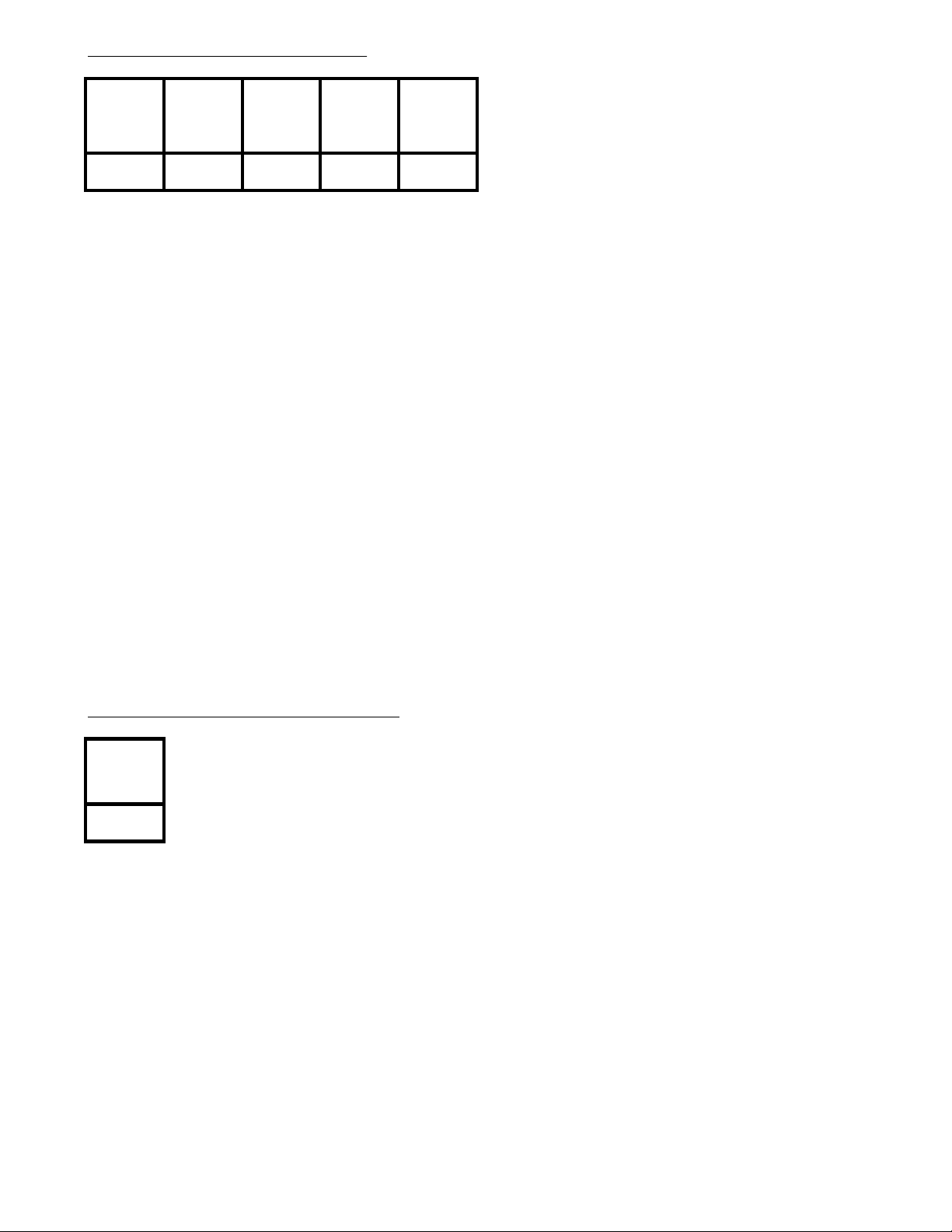
Program 86 - Line Options (3)
(Display shows: LINE ASSIGNMENT3)
(A.) Loop
Disconnect
Detection
Program Record Form Entry
1. Enter the desired option number in each feature's column.
System Program Entry
1. Ent er 86 (program nu mber).
2. Press *.
3. Enter the line number to be programmed.
4. Enter the data from columns A-E.
5. Press *.
6. Enter the data for the next line OR Press * to advance the
line numbers OR Press # to exit the program.
(B.) Not
Used
0000
(B.) Not
Used
(D.) Not
Used
(E.) Not
Used
Options
(A.) Loop Disconnect Detection
0=dis abled, 1=enabled
(B.) Not Used
Must be entered as "0".
(C.) Not Used
Must be entered as "0".
(D.) Not Us ed
Must be entered as "0".
(E.) Not Used
Must be entered as "0".
Program 87 - Hold Disable Time r
Hold
Disable
Timer
Program Record Form Entry
1. Enter the value to be used for the timer.
System Program Entry
1. Ent er 87 (program nu mber).
2. Press *.
3. Enter the value to be used for the timer.
4. Press *.
5. Press # to exit the program.
(Display shows: HD DISABLE TIMER)
Options
Hold Disable Timer:
000=can immediately place a call on
Hol d, 001-255 = 1 - 255 second delay
- 47 -
Page 56
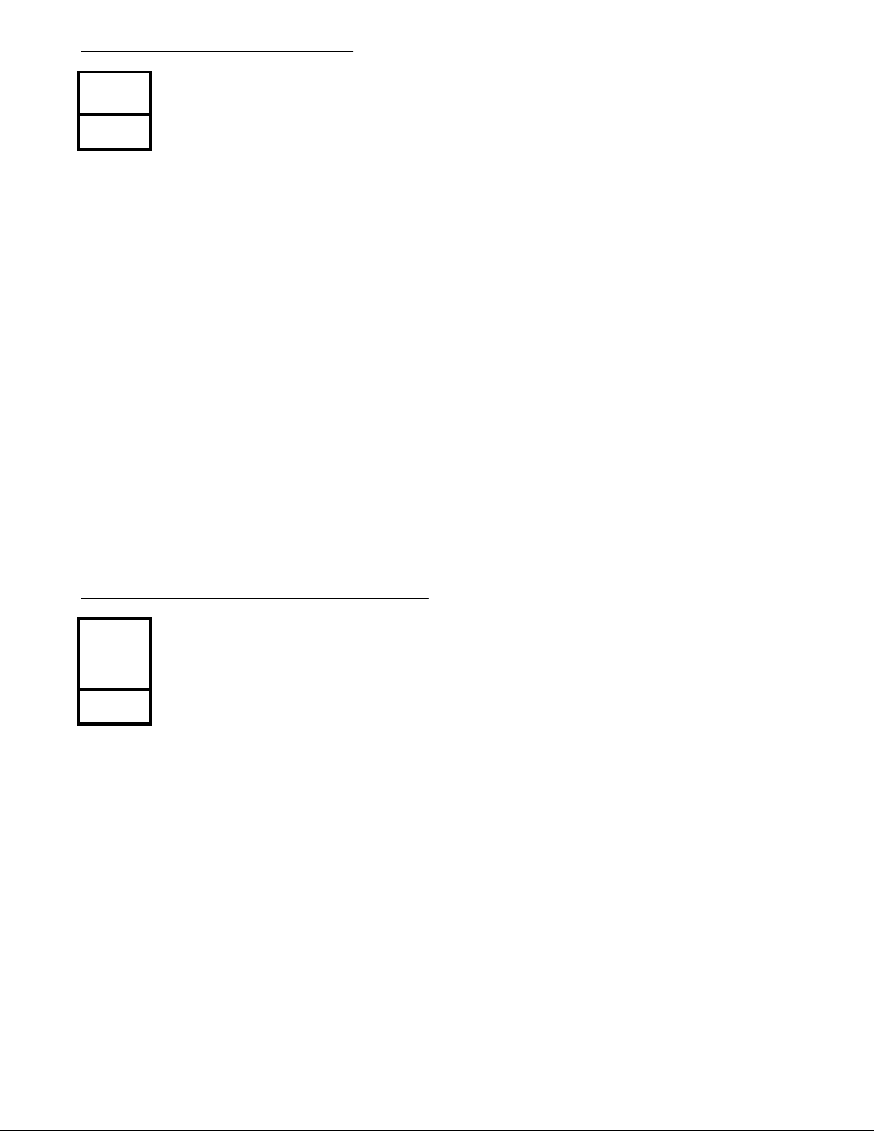
Program 88 - Door Relay Timer
(Display shows: DOOR RELAY TIMER)
Door Relay
Timer
Program Record Form Entry
1. Enter the value to be used for the timer.
System Program Entry
1. Ent er 88 (program nu mber).
2. Press *.
3. Enter the value to be used for the timer.
4. Press *.
5. Press # to exit the program.
Options
Door Relay Timer:
000=manual opera tion, 001-255 =
100 msec - 25.5 seconds
Program 89 - CO Dial Tone Delay Timer
CO Dial
Tone Delay
Timer
Program Record Form Entry
1. Enter the value to be used for the timer.
System Program Entry
1. Ent er 89 (program nu mber).
2. Press *.
3. Enter the value to be used for the timer.
4. Press *.
5. Press # to exit the program.
(Display shows: DIAL WAIT TIMER)
Options
CO Dial T one Delay Timer:
000=no delay , 001-255 = 100 msec -
25.5 second delay
- 48 -
Page 57
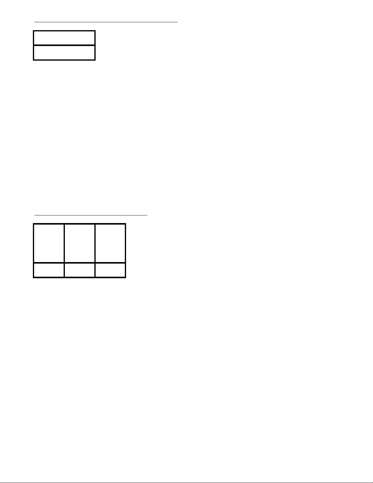
Program 92 - Program Entry Pa s s word
(Display shows: SYS.PRG.PASSWORD)
New Password
Program Record Form Entry
1. Enter the new system password (8 digits maximum).
System Program Entry
1. Ent er 92 (program nu mber).
2. Press *.
3. Enter the ne w system password.
4. Press *.
5. Press # to exit the program.
Program 95 - Sub-CPU Time r s
Options
Password:
Any digits between 0 and 9
(maximum of 8 digits)
(Display shows: SUB CPU TIMERS)
(1.) Flash
Detect
Timer for
SLT's
Program Record Form Entry
1. Enter the desired option number in each feature's column.
System Program Entry
1. Ent er 95 (program nu mber).
2. Press *.
3. Enter the item number to be programmed.
4. Press *.
5. Enter the data for the option being programmed.
6. Press *.
7. Enter the data for the next option OR Press # to exit the program.
(2.)
Incoming
Guard
Timer for
SLT's
(3.) Call
Abandon
Detect
Timer for
SLT's
Options
(1.) Fla s h Detect Timer for SLT's
025 - 119=250 msec-1190 msec
(2.) Inc oming Gu ard Timer for SLT's
001 - 127=100-12,700 msec
(3.) Call Abandon Detect Timer for SLT's
001 - 127=100-12,700 msec
- 49 -
Page 58

- 50 -
Page 59

Nitsuko America, Telecom Division
4 Forest Parkway
Shelton, CT 06484
TEL: 203-926-5400
FAX: 203-929-0535
Other Important Telephone Numbers
Sales: ...................................................................
Customer Service:................................................
Customer Service FAX:........................................
Technical Service: ...............................................
Discontinued Product Service: ............................
Technical Training:...............................................
Emergency Technical Service (After Hours): ......
(Excludes discontinued products)
203-926-5450
203-926-5444
203-926-5454
203-925-8801
900-990-2541
203-926-5430
203-929-7920
Page 60

 Loading...