

Page 1
User’s Manual
Page 2
E-3
Important Information
Precautions
Please read this manual carefully before using your NEC
Plasma Monitor and keep the manual handy for future reference.
RISK OF ELECTRIC SHOCK
DO NOT OPEN
CAUTION:
TO REDUCE THE RISK OF ELECTRIC
SHOCK, DO NOT REMOVE COVER. NO
USER-SERVICEABLE PARTS INSIDE.
REFER SERVICING TO QUALIFIED
SERVICE PERSONNEL.
This symbol warns the user that uninsulated
voltage within the unit may have sufficient
magnitude to cause electric shock. Therefore, it is dangerous to make any kind of
contact with any part inside of this unit.
This symbol alerts the user that important
literature concerning the operation and
maintenance of this unit has been included.
Therefore, it should be read carefully in
order to avoid any problems.
WARNING
TO PREVENT FIRE OR SHOCK HAZARDS, DO NO T EXPOSE
THIS UNIT TO RAIN OR MOISTURE. ALSO DO NOT USE
THIS UNIT'S POLARIZED PLUG WITH AN EXTENSION CORD
RECEPT A CLE OR OTHER OUTLETS , UNLESS THE PR ONGS
CAN BE FULLY INSERTED. REFRAIN FROM OPENING THE
CABINET AS THERE ARE HIGH-VOLTAGE COMPONENTS
INSIDE. REFER SERVICING TO QUALIFIED SERVICE PERSONNEL.
WARNING
This is a Class A product. In a domestic en vironment this product
may cause radio interference in which case the user may be required to take adequate measures.
CAUTION
Warnings and Safety Precaution
The NEC Plasma monitor is designed and manufactured to provide long, trouble-free service. No maintenance other than cleaning is required. Use a soft
dry cloth to clean the panel. Never use solvents such
as alcohol or thinner to clean the panel surface.
The plasma display panel consists of fine picture elements (cells). Although NEC produces the plasma display panels with more than 99.99 percent active cells ,
there may be some cells that do not produce light or
remain lit.
For operating saf ety and to a v oid damage to the unit,
read carefully and observe the following instructions.
To avoid shock and fire hazards:
1. Provide adequate space for ventilation to avoid internal heat build-up. Do not cover rear vents or install in a
closed cabinet or shelves.
The unit is equipped with cooling fans. If you install
the unit in an enclosure, be sure there is adequate space
at the top of the unit to allow hot air to rise and escape.
If the monitor becomes too hot, the overheat protector
will be activated and the monitor will be turned off. If
this happens, turn off the power to the monitor and unplug the power cord. If the room where the monitor is
installed is particularly hot, move the monitor to a cooler
location, and wait for the monitor to cool for 60 minutes. If the problem persists, contact your NEC dealer
for service.
2. Do not use the power cord polarized plug with extension cords or outlets unless the prongs can be completely
inserted.
3. Do not expose unit to water or moisture.
4. Avoid damage to the power cord, and do not attempt to
modify the power cord.
5. Unplug unit during electrical storms or if unit will not
be used over a long period.
6. Do not open the cabinet which has potentially dangerous high voltage components inside. If the unit is damaged in this way the warranty will be void. Moreover,
there is a serious risk of electric shock.
7. Do not attempt to service or repair the unit. NEC is not
liable for any bodily harm or damage caused if unqualified persons attempt service or open the back cover.
Refer all service to authorized NEC Service Centers.
8. Do not attempt to install or mount the unit yourself.
Please contact your NEC dealer for installation.
Page 3
E-4
To avoid damage and prolong operating life:
1. Use only with 100-240V 50/60Hz AC power supply.
Continued operation at line voltages greater than 240
Volts AC will shorten the life of the unit, and might
even cause a fire hazard.
2. Handle the unit carefully when installing it and do not
drop.
3. Locate set away from heat, excessive dust, and direct
sunlight.
4. Protect the inside of the unit from liquids and small
metal objects. In case of accident, unplug the unit and
have it serviced by an authorized NEC Service Center.
5. Do not hit or scratch the panel surface as this causes
flaws on the surface of the screen.
6. As is the case with any phosphor-based display (like a
CRT monitor, for example) light output will gradually
decrease over the life of a Plasma Display Panel.
NOTE:
When you connect a computer to this monitor, attach
the supplied ferrite cores. If you do not do this, this
monitor will not comform to mandatory CE or C-Tick
standards.
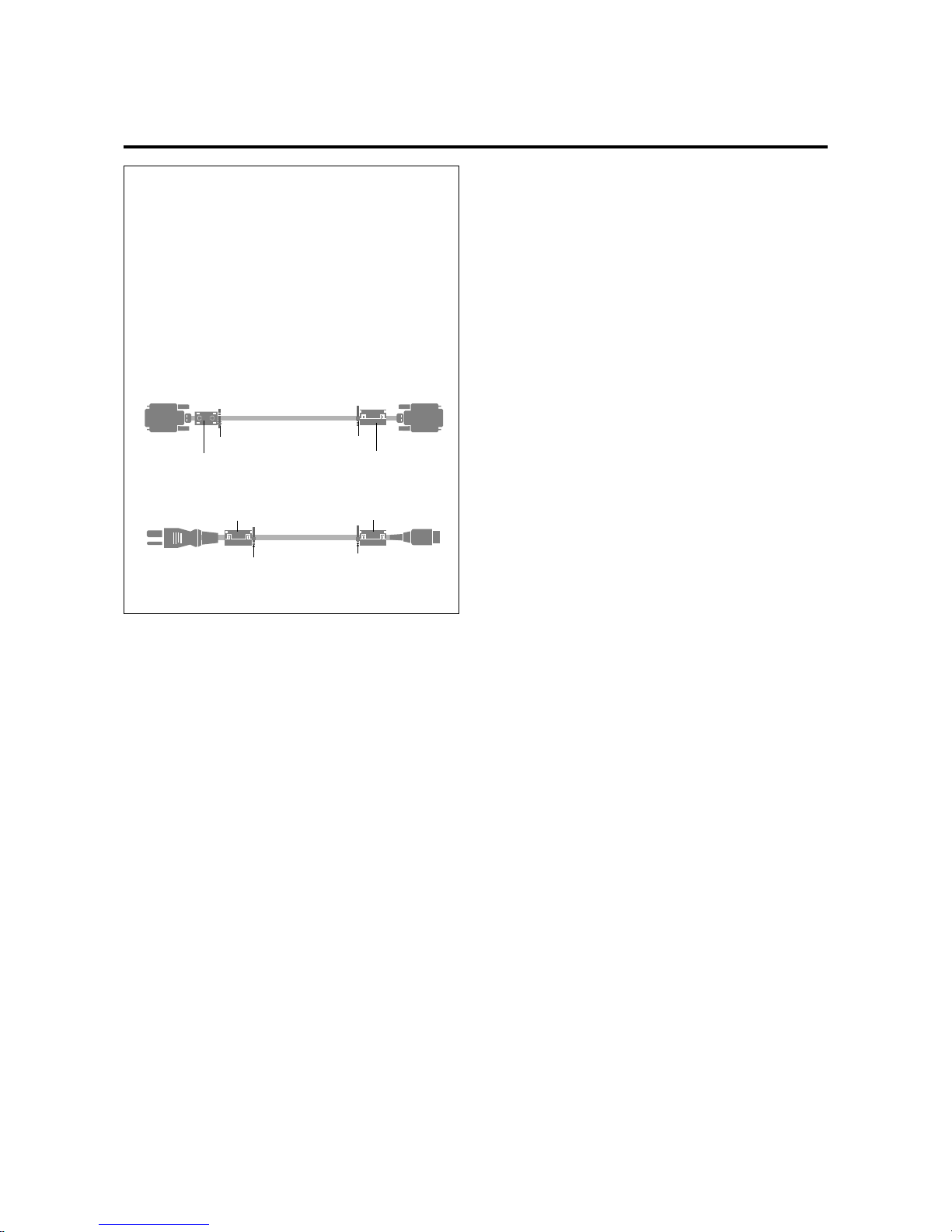
Attaching the ferrite cores.
Set the ferrite cores on the both ends of the DVI cable
(not supplied), and the both ends of the power cable
(supplied).
Close the lid tightly until the clamps click.
Use the band translation you requested.
Set side
(Plasma Monitor side)
DVI cab le (not supplied)
core (small)
core (small)
Connector
Power cable (supplied)
core (large)
core (large)
band
band
band
band
Recommendations to avoid or minimize phosphor b urn-in
Like all phosphor-based display devices and all other gas
plasma displays, PlasmaSync monitors can be susceptible
to phosphor burn under certain circumstances. Certain
operating conditions, such as the continuous display of a
static image over a prolonged period of time, can result in
phosphor burn if proper precautions are not taken. To protect your investment in this NEC PlasmaSync monitor,
please adhere to the following guidelines and recommendations for minimizing the occurrence of image burn:
* Always enable and use your computer's screen saver
function during use with a computer input source.
* Display a moving image whenever possible.
* Always power down the monitor when you are finished
using it.
NEC has built-in several operating modes in your
PlasmaSync PD Series monitor to help you reduce the
likelihood of phosphor burn. These are called the
AccuShield Phosphor Protection System. If the
Plasmasync monitor is in long-term use or continuous operation, use the functions available in AccuShield to reduce the likelihood of perceptible phosphor burn or to diminish its perceptible effects if it occurs. See pages E-40
and E-43 for instructions on how to use the Orbiter, Low
Brightness and Inverse RGB modes of AccuShield.
* Lower the Brightness and Contrast levels as much as
possible without impairing image readability.
(See page E-22, E-27)
* Display an image with many colors and color gradations
(ie. photographic or photo-realistic images).
* Create image content with minimal contrast between light
and dark areas, for example white characters on black
backgrounds. Use complementary or pastel color when-
ever possible.
* Avoid displaying images with few colors and distinct,
sharply defined borders between colors.
Contact NEC affiliates on authorized dealer for other recommended procedures that will best suit your particular
application needs.
Burn-in not covered by the warranty.
Page 4

E-5
Contents
How to Attacch Options to the Plasma Monitor ..........................................................................................E-6
Introduction
Introduction to the PlasmaSync 42PD2/50PD1 ............................................................................. E-7
The features you’ll enjoy include .................................................................................................. E-7
Contents of the Package............................................................................................................... E-7
OPTIONS................................................................................................................................... E-7
Setup Procedure ........................................................................................................................................ E-8
Part Names and Functions
Front View ............................................................................................................................... E-10
Side View Terminal Board L/R................................................................................................... E-11
Remote Controller..................................................................................................................... E-12
Battery Installation and Replacement ..........................................................................................................
E-13
Operating Range / Using the wired remote control mode .............................................................................E-14
Making the DIP Switch Settings
DIP Switch Functions and Settings .............................................................................................. E-15
Power Management Function .................................................................................................... E-16
Power Management Modes....................................................................................................... E-16
Installation
Wiring Diagram....................................................................................................................... E-17
Connecting Your PC or Macintosh Computer .............................................................................. E-18
Connections with Equipment that has a Digital Interface .............................................................. E-18
Connecting Your VCR or Laser Disc Player ................................................................................. E-18
Connecting Your Document Camera .......................................................................................... E-18
Daisy-chaining Your monitors.................................................................................................... E-19
Operation
Power/General Controls/Adjustment of the Display .................................................................... E-20
Adjustment of the Display (Direct) .............................................................................................. E-21
Returning the Screen Adjustment to the Factory Default Settings (NORMAL) .................................. E-21
Adjustment of the Image ........................................................................................................... E-22
Returning the Image Adjustments to the Factory Default Settings (NORMAL).................................. E-22
Adjustment of the Display (Menu Control)
List of Setting Details ................................................................................................................. E-23
Before Making Adjustments....................................................................................................... E-24
To Reset the Adjustment Value (to the Factory Default Setting) During the Setting............................ E-25
Adjustment of the Image (Visual Controls)................................................................................... E-27
Adjustment of Screen Position (Horizontal) ................................................................................. E-28
Adjustment of Screen Position (Vertical) ...................................................................................... E-29
Color Temperature .................................................................................................................... E-30
Adjustment of the White Balance ............................................................................................... E-31
Adjustment of the On-screen Display Position ............................................................................. E-32
Setting the On-screen Display OFF Time..................................................................................... E-33
Adjustment of the Clock Frequency/Clock Phase (AUTO PICTURE) ............................................... E-34
Normal Screen......................................................................................................................... E-35
Next Page Screen..................................................................................................................... E-36
Information Screen ................................................................................................................... E-37
Timer Screen ............................................................................................................................ E-38
Auto Timer Screen .................................................................................................................... E-39
Multiple Screens ....................................................................................................................... E-41
Other Setting Screens (1) .......................................................................................................... E-42
Other Setting Screens (2) .......................................................................................................... E-43
Set Selection Screen for Allotting ID Numbers to Multiple Screens/Each Set .................................. E-44
Troubleshooting.......................................................................................................................................E-45
Specifications .......................................................................................................................................... E-46
Appendix
Signal Identification For Raster Preset......................................................................................... E-48
Pin Configuration and Signal Level of mini D-Sub 15-Pin (Analog) Input Connector ....................... E-49
Pin Configuration and Signal of the RGB 3 IN Connector (DVI Connector) .................................... E-49
Function and Pin Configuration of the External Control Connector ................................................ E-50
Cabinet dimensions ................................................................................................. E-61
Page 5
E-6
How to Attach Options to the Plasma Monitor
Drawing A
Drawing B
45mm (1.77")
50
mm (1.97")
50
mm (1.97")
31
mm
(1.22")
31
mm
(1.22")
Wall
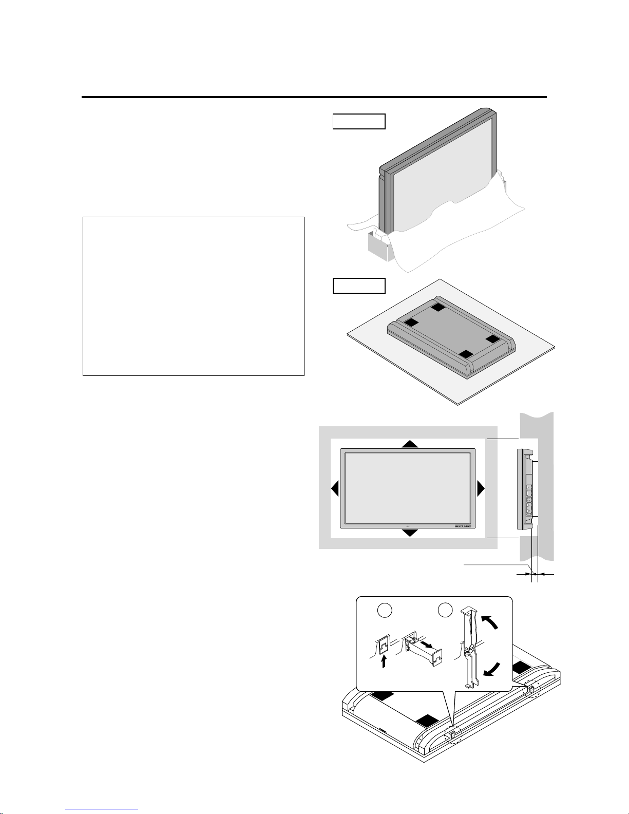
Ventilation Requirements for enclosure mounting
To allow heat to disperse, leave space between surrounding objects as shown in the diagram to the right.
You can attach your optional mounts or stand to the plasma
monitor in one of the following two ways:
* In the upright position. (See Drawing A)
* Lay the screen face down (See Drawing B). Lay the
protective sheet, which was wrapped around the monitor
when it was packaged, beneath the screen surface so as
not to scratch the screen face.
This device cannot be used or installed without a separate Tabletop Stand or other optional mounting accessory. For proper installation it is strongly recommended to use a
trained, NEC authorized serviceman. Failure
to follow correct mounting procedures could
result in damage to the equipment or injury to
the user or installer. Product warranty does
not cover damage caused by improper installation. Failure to follow these recommendations could result in voiding your warranty.
Notice:
* Installation of only the main unit is not possible. Be sure
to use and install the main unit in conjunction with a
stand or special unit.
Note:
RETRACTABLE FEET ARE FOR TEMPORARY USE
ONLY AND ARE NOT INTENDED FOR PERMANENT INSTALLATION.
MODEL # PX-42VPU1-ST STAND IS REQUIRED
FOR PERMANENT TABLETOP INSTALLATION.
REPLACE THE FEET WHEN YOU MOVE THE
MONITOR.
2
1
Pulling Out and Reinserting the
Retractable Feet
The Retractable Feet are housed at 2 locations on the bottom surface of the main unit.
1. Grasp the end and pull out.
2. The feet will open automatically when your hand is removed.
To house the Retractable Feet, close them and then
continue to push them inside the main unit.
Page 6

E-7
Introduction
Contents of the Package
The following lists all of the items included in your
PlasmaSync monitor package. Please save the original
box and packing materials for future transportation or
shipment of this monitor.
1. PlasmaSync 42PD2/50PD1
2. Power cord
3. Wireless/Wired remote control unit and two AAA
batteries
4. Remote cable
5. RGB cable (15-Pin mini D-Sub To 15-pin mini D-Sub
Connector)
6. User' s manual
7. Two cores (large) and two cores (small)
OSM and IPM are trademarks of NEC Technologies, Inc.
IBM PC/AT, PS/2, VGA, S-VGA, 8514/A and XGA are
registered trademarks of International Business Machines
Corporation.
Apple and Macintosh are registered trademarks of Apple
Computer, Inc.
Microsoft is a registered trademark of Microsoft
Corporation. Windows is a trademark of Microsoft
Corporation.
Introduction to the PlasmaSync
42PD2/50PD1
This section introduces you to your new PlasmaSync 42PD2/
50PD1, provides a list of materials that comes with your
monitor and describes the features and controls.
The features you’ll enjoy include:
* This unit can be used with IBM PC/AT, Macintosh, and
compatibles.
(For details, see “Factory Setting Values Preset Table.”
E-48)
* Easy-to-operate multifunction remote control and exter-
nal control connector
A single remote control can be used as a wireless or as a
wired remote control (with automatic switching by cable connection) and the remote THROUGH OUT connector permits simultaneous operation of multiple monitors.
(A maximum of 3 units can be connected.)
The external control connector with a THROUGH OUT
feature permits various control functions to be made ex-
ternally.
* ID No. settings can be made for up to 256 units.
* NTSC, PAL, SECAM, and M-NTSC composite video
signals can be accommodated
Video signals from video cameras, video decks, video
disc players, and other video equipment adhering to
NTSC as well as PAL, SECAM, and M-NTSC (with a
4.43 MHz chroma signal) standards can be selected on
screen.
* Varied set of input connectors
Video input signals: BNC video connector, S video con-
nector. Each type is equipped with its own THROUGH
OUT connector, single system.
Analog RGB input: mini D-Sub 15-pin connector, BNC
(R, G, B, H/CS, V connectors). BNC is equipped with its
own THROUGH OUT connector, single system.
* Can be used with Digital RGB input (DVI standard com-
pliant)
* Can be used with multiple screens
* Power management function
RGB3 input mode complies with DMPM (Digital Moni-
tor Power Management) of DVI.
A great reduction in power consumption when not being
used is achieved through the VESA-proposed DPMS
system.
The unit can also be used with the Energy Star standard
(in which case power consumption will be 15 W or less
when not being used).
* The personal computer and the operating system that are
to be connected must be compatible with VESA DPMS.
Personal computers that are to be connected to the RGB3
input must be compatible with DVI DMPM.
* OSM (On Screen Manager) function
The OSM function displays a variety of screen adjustment and correction menus on the screen to allow fine
settings to be made.
* Plug and Play compatible
The RGB3 input is compatible with DDC2B only.
Ready to be used with Plug and Play which are supported
by Windows 98 and Windows 95.
(VESA DDC1 and DDC2 level B)
* Windows 98 or Windows 95 and a personal computer
with VESA DDC are required to use Plug and Play.
* Can be used with RS-232C
Page 7

E-8
1.Determine the installation location
* To ensure safe use, see “Before Use” and “Observe
the Following,” then install properly.
2.Connect the equipment
Set the termination switch (75Ω/high impedance).
Set the DIP switches to suit the application and system
structure. (See Page E-15.)
(Loop-out connections are for one unit, maximum.)
3.Install the remote control batteries.
* To use the remote control in the wired arrangement,
connect the supplied remote control cable.
4.Connect the supplied power cable
* The maximum current rating 5.6(A) : 42PD2
* The maximum current rating 7.4(A) : 50PD1
5. Switch on the power of each of the
devices
* When connected with a computer, switch on the
power of the computer first.
6.Input an analog RGB signal or a video
signal to this unit
7.Select the input mode
* Select the appropriate RGB input or video input.
8.Adjust the screen
* Make adjustments when adjustment of the screen
display position or distortion is required.
9.Adjust the image
* Make adjustments when adjustment of the tint, bright-
ness, or contrast is required.
Setup Procedure
Warning
For proper installation and mounting it is strongly recommended to use a trained, authorized NEC dealer.
Failure to follow correct mounting procedures could result in damage to the unit or injury to the installer.
Product warranty does not cover damage caused by improper installation.
Notice:
This monitor requires the use of a tabletop stand or wall
mount unit for permanent installation and use.
This monitor cannot be used without one of these accessories.
Note:
RETRACTABLE FEET ARE FOR TEMPORARY USE
ONLY AND ARE NOT INTENDED FOR PERMANENT INSTALLATION.
MODEL # PX-42VPU1-ST STAND IS REQUIRED
FOR PERMANENT TABLETOP INSTALLATION.
REPLACE THE FEET WHEN YOU MOVE THE
MONITOR.
Page 8
E-9
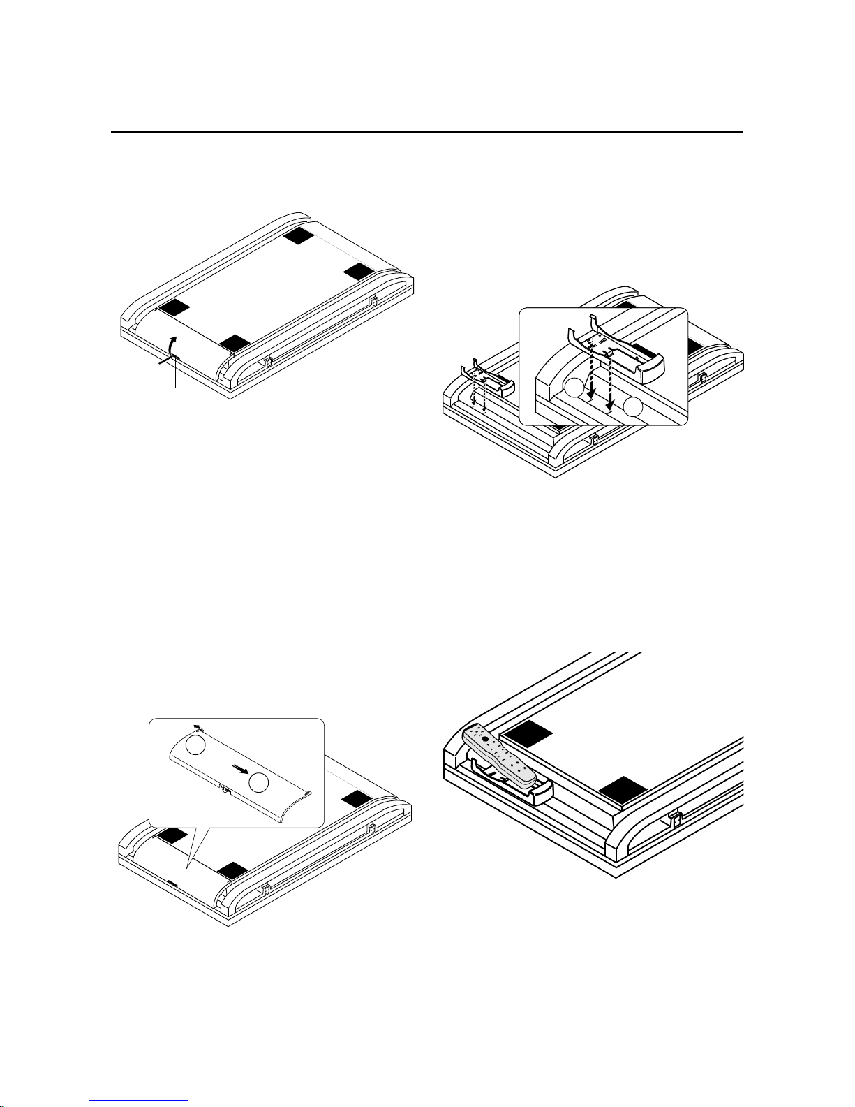
Opening the Terminal Board
Cover
Slide the knob and at the same time lift the cover.
Knob
Removing the Terminal Board
Cover
This unit’s terminal board cover can be removed.
First, open the cover and then:
1. Pull the top hook in the direction of the arrow.
2. Pull the entire terminal board cover downward.
To attach the terminal board cover, insert the bottom hook
into the hole, then pull the top hook and insert it into the
hole.
Hook
Attaching the Remote Control
Holder
Insert the top hook of the remote control holder into the
installation hole of the main unit and then insert the bottom hook into its respective hole.
To remove the remote control holder, first release the bottom hook, then release the top hook.
1
2
Housing the Remote Control in
the Remote Control Holder
First insert the bottom part of the remote control and continue to push it in until the top part clicks into place.
To remove, lift the remote control up from the top part and
remove it from the holder.
1
2
Page 9
E-10
Part Names and Functions
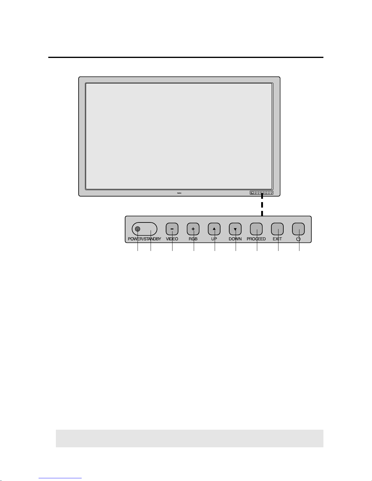
Front View
1 POWER/STANDBY
The lamp color indicates the mode of power on/standby
or power management.
2 Remote control sensor
Receives the signal from the remote control (when using
the wireless remote control).
3 VIDEO button
Switches to the signal connected with the VIDEO input
connector.
Functions as the (-) button in the on-screen display
(OSM) mode.
4 RGB button
Switches to the signal connected with the RGB input
connector. (Toggle switches between RGB1/RGB2/
RGB3.)
Functions as the (+) button in the on-screen display
(OSM) mode.
5 UP button
Functions as the (▲) button in the on-screen display
(OSM) mode.
6 DOWN button
Functions as the (▼) button in the on-screen display
(OSM) mode.
7 PROCEED button
Sets the on-screen display (OSM) mode and displays
the on-screen menu.
8 EXIT button
Exits the on-screen display (OSM) mode.
9 POWER button
Switches the main power on/off.
12
3
495678
Note:
When the “CONTROL LOCK” toggle switc h on the monitor’s input panel is set to “ON”, the buttons on the
set’s front bezel control panel do not function.
Page 10
E-11
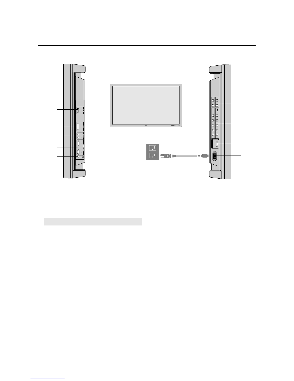
Side View.... Terminal Board L/R
10
11
12
13
AC-IN
OUT
IN
RGB1
HIGH 75Ω
RGB2
VIDEOG B H/CS
V
R S-VIDEO
10 DIP SW
Sets the various modes of this unit.
11 RGB3 (DVI 29pin)
IN connector: Inputs a digital RGB signal. (TMDS)
Note:
This connector does not support analog input.
12 REMOTE (Mini jack)
IN jack: This jack connects the wired remote control.
THROUGH OUT jack: Outputs as is the remote con-
trol signal that is connected to the REMOTE IN jack.
* This is used when operating multiple monitors (i.e., of
this unit) with a single remote control.
13 EXTERNAL CONTROL (mini D-Sub 15 pin)
Controlled by the computer’s RS-232C interface.
IN connector: Used when operating this unit with
EXTERNAL CONTROL from a personal computer.
THROUGH OUT connector: Outputs as is the signal
that is input to the EXTERNAL CONTROL IN connector.
14 CONTROL LOCK
When “CONTROL LOCK” is set to “ON”, the buttons
on the set’s front bezel control panel do not function.
14
15
16
17
18
15 VIDEO
IN [BNC] connector (BNC): Inputs the video (com-
posite video signal).
IN [S] connector (DIN 4 pin): Inputs the S video (Y/
C separate signal).
*When connections are made to both the BNC connec-
tor and the S video connector, the signal of the S video
connector has priority.
THROUGH OUT [BNC] connector (BNC): Outputs
the same signal connected to the VIDEO IN [BNC]
THROUGH OUT [S] connector (DIN 4 pin): Outputs the same signal connector to the connector. connector.
16 RGB2 [R, G, B, H/CS, V] (BNC)
IN connector: Inputs the analog RGB signal.
The H/V composite signal is connected to the H/CS
connector.
THROUGH OUT connector: Outputs as is the signal
input to the RGB2 IN connector.
75Ω/HIGH switch: This switch selects the impedance
of the connector. It is usually used in the “75Ω” position.
17 RGB1 (mini D-Sub 15 pin)
IN connector: Inputs the analog RGB signal of a per-
sonal computer, etc.
18 AC IN connector
Connects with the supplied power cable.
Insert the prongs completely.
* for PLUGGABLE EQUIPMENT, tee
socket-outlet shall be installed near the
equipment and shall be easily accessible.
Page 11

E-12
POWER
ON
POWER
OFF
RGB 1
RGB 2
POSITION / CONTROL
RGB 3
EXIT
PROCEED
VIDEO
CONTRAST
RGB/VIDEO
BRIGHT
COLOR
VIDEO
TINT
SHARPNESS
VISUAL
NORMAL
RASTER
NORMAL
ID SELECT CLEAR
1
1 POWER ON/OFF button:
Switches the power on/off.
(If the POWER/STANDBY let is not glowing, then
these controls will not work.)
2 Input selection buttons:
Select the input signal that will be displayed on the
screen.
VIDEO: Switches to the signal that is connected to the
VIDEO IN connector.
RGB1: Switches to the signal that is connected to the
RGB1 IN (mini D-sub 15-pin) connector.
RGB2: Switches to the signal that is connected to the
RGB2 IN (BNC type: R, G, B, H/CS, V) connector.
RGB3: Switches to the signal that is connected to the
RGB3 IN connector.
RASTER CONTROL (Screen Adjustment)
3 POSITION/CONTROL buttons (▲▼§ ©):
Used for screen position adjustment and on-screen
manager (OSM) mode adjustment settings.
4 POSITION/CONTROL buttons (§ ©):
Enable item selection and adjustments/settings.
ON SCREEN (Screen and Image Adjustment via Menu
Control)
5 PROCEED button:
Displays the main menu of screen and image adjustments.
Press this button during the display of the main menu
to go to the sub menu.
6 EXIT button:
Exits the on-screen adjustments.
Press this button during the display of the sub menu to
return to the main menu.
VISUAL CONTROL (Image Adjustment)
7 CONTRAST button:
Adjusts the contrast of the RGB signal and the video
signal.
8 BRIGHT button:
Adjusts the brightness of the RGB signal and the video
signal.
9 COLOR button:
Adjusts the saturation of the video signal colors.
10 TINT button:
Adjusts the tint of the video signal.
(Does not function in the PAL or SECAM settings.)
2
4
6
7
8
9
10
11
12
14
16 17
3
5
13
15
Remote Controller
Page 12
E-13
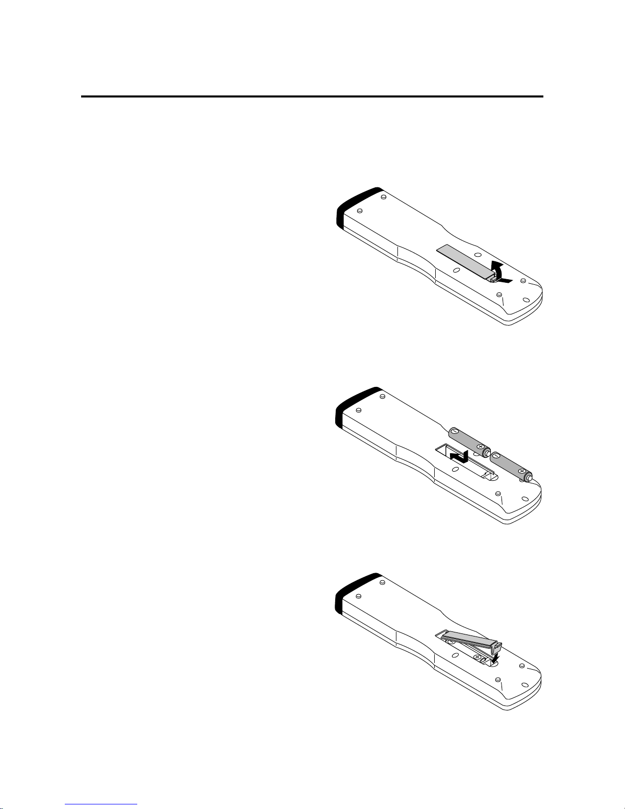
1. Press and open the cover.
2. Align the batteries according to the (+) and (-)
indications inside the case.
3. Replace the cover.
Battery Installation and Replacement
The remote control is powered by two 1.5V AAA batteries.
11 SHARPNESS:
Adjusts the fine screen quality of the video screen.
12 VISUAL NORMAL button:
Returns the screen adjustments to the default factory
visual settings.
13 RASTER NORMAL button:
Returns the screen adjustments to the default factory
raster settings.
14 ID SELECT:
Selects the ID number of each monitor in a video wall
so that each monitor can be adjusted with the remote
control one at a time.
15 CLEAR:
Deletes the ID number that was set with ID SELECT.
16 Remote control transmitter:
Transmits the remote control signal. (Used with the
wireless remote control.)
17 Remote jack:
Connects the supplied remote control cable when used
as a wired remote control.
Page 13
E-14
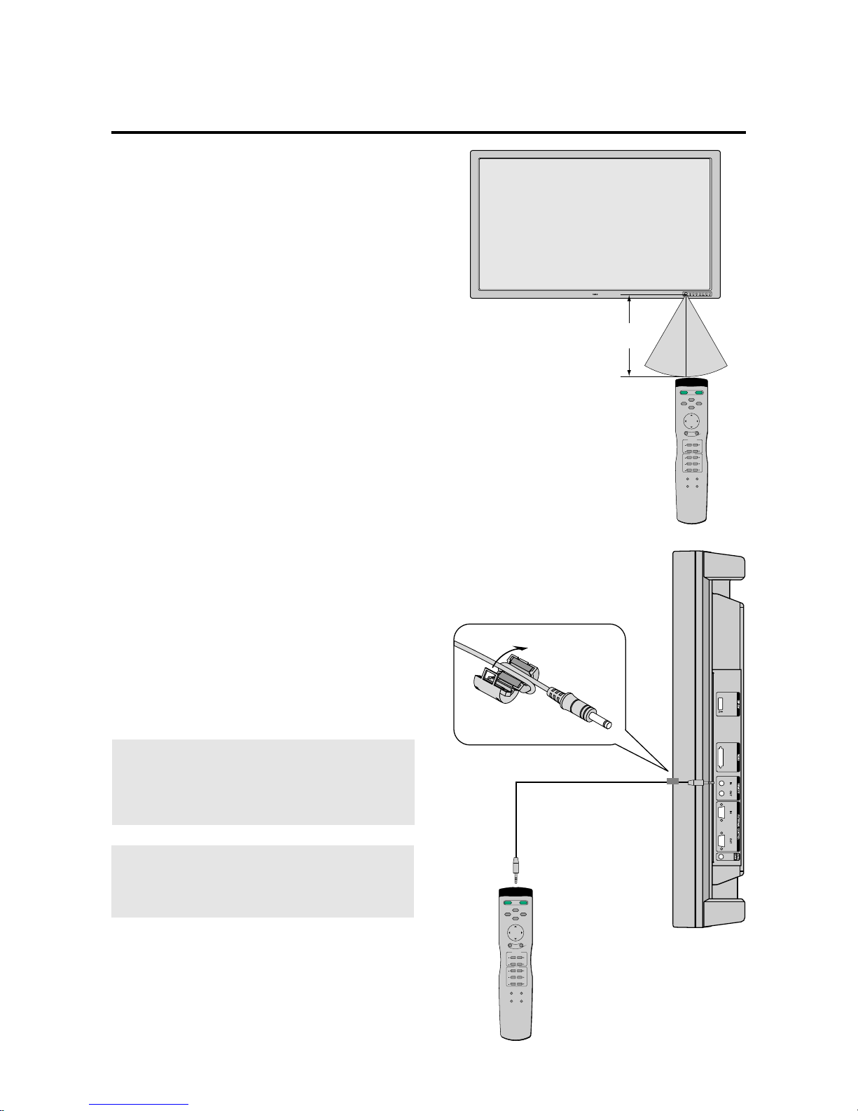
Using the wired remote control mode
Connect the included remote control cable to the remote
control's remote jack and "REMOTE IN" jack on the
monitor.
When the cable is connected, the mode automatically
switches to wired remote control.
When the wired remote control mode is used, the remote
control unit can be operated even if no batteries are loaded.
Operating Range
* Use the remote controller within a distance of about 7 m
/ 23ft. from the front of the monitor's remote control sensor and at a horizontal angle of within 30°.
* The remote control operation may not function if the
monitor's remote control sensor is exposed to direct sunlight or strong artificial light, or if there is an obstacle
between the sensor and the remote control unit.
Note:
Do not connect the wired r emote control to the REMO TE
THROUGH OUT jack. If doing so, the remote control
does not work.
Remote Control Cable
To Remote Jack
POWER
ON
POWER
OFF
RGB 1
RGB 2
POSITION / CONTROL
RGB 3
EXIT
PROCEED
VIDEO
CONTRAST
RGB/VIDEO
BRIGHT
COLOR
VIDEO
TINT
SHARPNESS
VISUAL
NORMAL
RASTER
NORMAL
ID SELECT CLEAR
Approx.
7m/23ft
30˚ 30˚
POWER
ON
POWER
OFF
RGB 1
RGB 2
POSITION / CONTROL
RGB 3
EXIT
PROCEED
VIDEO
CONTRAST
RGB/VIDEO
BRIGHT
COLOR
VIDEO
TINT
SHARPNESS
VISUAL
NORMAL
RASTER
NORMAL
ID SELECT CLEAR
Note:
When you connect a remote control cable to this monitor , attach the supplied ferrite core. If you do not do
this, this monitor will not conform to mandatory FCC
standards. (42PD2 only)
Page 14
E-15
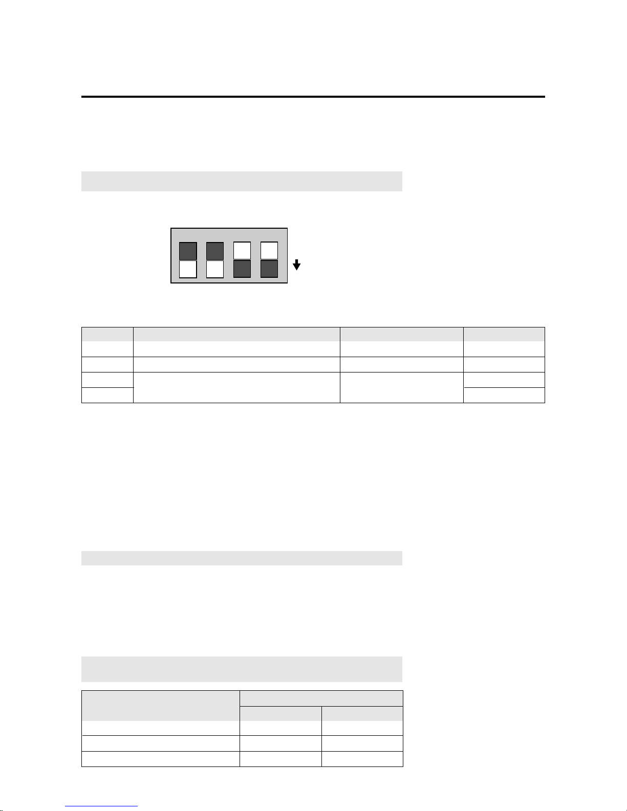
Setting details
On-off switching of on-screen display (OSM)
On-off switching of wireless remote control
Setting when shipped
On
On
Switch position
ON
ON
OFF
OFF
Sync control mode
Automatic selection
PIn No.
1
2
3
4
Automatic
Manual 1 (Composite)
Manual 2 (Sync-on-green)
No.4
OFF
ON
OFF
Sync control setting
No.3
OFF
OFF
ON
Switch position
Making the DIP Switch Settings
Before connections are made, the DIP switch should be set to suit the application and
the system structure.
* DIP switches are moved up or down with something fine and pointed such as a
miniature screwdriver or the tip of a ballpoint pen.
Note:
Be sure to switch off the main power before making settings.
1 2 3 4
ON
DIP Switch Functions and Settings
Factory Default Settings
No. 1: On/off switching of on-screen display (OSM)
* Set to “ON” when performing adjustments and viewing displays with the on-screen
display.
Set to “OFF” when displays are not desired.
No. 2: On/off switching of wireless remote control
* When using multiple units under wireless remote control operation, the remote
control signal also enters other monitors and may control them at the same time.
Monitors for which the reception of the wireless remote control signal is not desired
should be set to “OFF.”
* Be sure to switch the units on when the wireless remote control is to be used.
Note:
that use of the wired remote control is not related to this setting.
Pin Nos. 3 and 4 Sync Control Settings
* These are settings of the input sync signals.
* When this unit is set to automatic, it automatically detects the separate sync,
composite sync, and green sync (sync-on-green).
Separate sync should be recgnized automatically.
Note:
When both pins No. 1 and No. 2 ar e set “ON” the synchronization may be
disturbed. Do not set both these pins “ON.”
Page 15
E-16
Power Management Function
The power management function is an energy saving function that automatically reduces the power consumption of the
display when the keyboard or the mouse have not been used for a fixed period. The power management function of the
display becomes operational when the monitor is used with a personal computer based on the VESA DPMS and DVI
DMPM system.
When preparing to display a personal computer screen, check that the personal computer is properly connected to this unit
and that the personal computer power is on.
When the personal computer power is off, the po w er management function will be acti vated and this unit will be set to the
off mode.
For information about the power management setting method, see the operating system (OS) manual of the personal
computer you are using. To see the video when the power management function is operating, setting the input selection to
video will switch the function off.
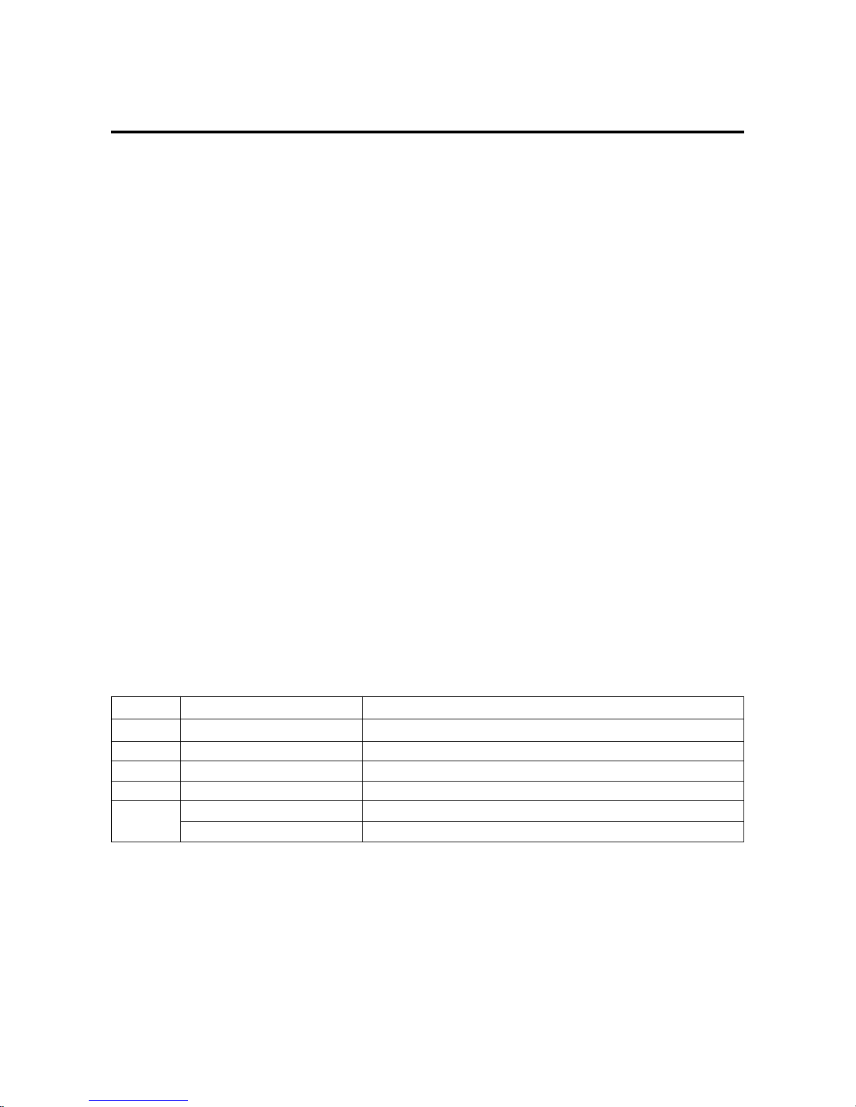
Power Management Modes
There are three modes in the power management function.
* Standby mode
The standby mode is set when the horizontal sync signal from the personal computer is not input.
The image will be displayed immediately upon the input of the horizontal sync signal.
* Suspend mode
The suspend mode is set when the vertical sync signal from the personal computer is not input.
The image will be displayed about 4 seconds after the input of the vertical sync signal.
* Off mode
This unit is set to the off mode when the horizontal/vertical sync signals from the personal computer are not input.
The image will be displayed about 4 seconds after the input of the horizontal/vertical sync signal.
This is the only power management mode using RGB3 input. When there is no TMDS link, the off mode is set. (This
power state is equivalent to the DPMS “off” state.) Displayed approximately 4 seconds after the TMDS link is restored.
The color in which the STANDBY/POWER lamp lights indicates the mode (listed below) in which the unit is set.
Mode
Power ON
Standby
Suspend
OFF
* Standby suspend, off in the table is the condition that exists when power management is ON.
This is not the standby condition set by the remote control.
STANDBY/POWER lamp display
Green
Yellow
Orange
Orange
Orange
Not lit
Notes
---Immediate return to normal display
15 W or less, returns to normal display in about 4 seconds
Maximum 8 W or less, returns to normal display in about 4 seconds
Remote control in standby mode
Power cord not connected
Power OFF
*
*
*
Page 16
E-17
Installation
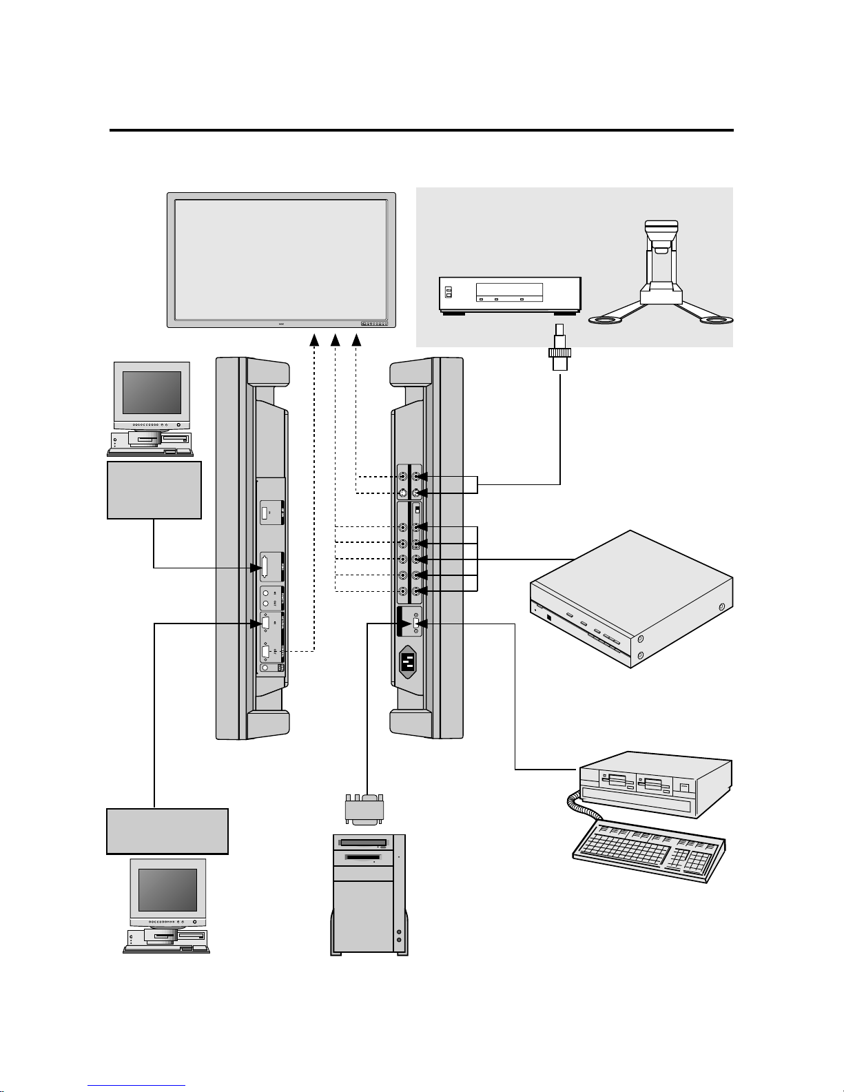
Wiring Diagram
AC-IN
OUT
IN
RGB1
HIGH 75Ω
RGB2
VIDEOG B H/CS
V
R S-VIDEO
EXTERNAL
CONTROL
Plasma monitor
IBM XGA/SuperVGA/VGA or
Compatibles or Macintosh G3 series
Macintosh or
Compatibles
Document camera VCR, Video copy
stand or Multimedia application
RGBcable (Supplied)
To mini D-SUB 15 Pin input
To R,G,B,H/CS, V inputs
(BNC)
To VIDEO IN inputs
Pin adapter for Macintosh
(not supplied)
RGBcable (Supplied)
To mini D-SUB 15 Pin input
To EXTERNAL CONTROL
(mini D-SUB 15 Pin input)
External equipment
e.g., Personal computer
To RGB3 DVI 29pin
(not supplied)
Personal computer
with a digital
RGB (TMDS) output
HIROYUK AIZASUSUSUSUSSWA
HIROYUK AIZ
Scan Converter
Page 17

E-18
Connecting Your PC or Macintosh
Computer
Connecting your PC or Macintosh computer to your
Plasma monitor will enable you to display your
computer's screen image. All of these following display
standards are supported:
To connect to a PC, Macintosh or computer equipped with
an XGA/SuperVGA/VGA adapter or compatible graphics
adapter, simply:
1. Turn off the power to your monitor and computer.
2. If your PC does not support XGA/SuperVGA/VGA
you will need to install an XGA/SuperVGA/VGA
graphics board. Consult your computer's owner's
manual for your XGA/SuperVGA/VGA configuration.
If you need to install a new board, see the manual that
comes with your new graphics board for installation instructions.
3. Use the signal cable that’s supplied to connect your PC
or Macintosh computer to the RGB1 input terminal.
4. Turn on the monitor and the computer.
Note:
Refer to your computer's owner's manual for
more information about your computer's video output
requirements and any special identification or
configuring your monitor's image and monitor may
require.
Connecting Your VCR DVD or
Laser Disc Player
Use a composite video cable with BNC connector and
RCA video cables (not provided) to connect your VCR,
DVD or laser disc player to your PlasmaSync monitor.
To make these connections, simply:
1. Turn off the power to your monitor and VCR, DVD or
laser disc player.
2. Connect one end of your video cable to the video output connector on the back of your VCR, DVD or laser
disc player, connect the other and to the VIDEO input
terminal (BNC type) of the monitor.
NOTE:
You will need a BNC to RCA adapter (not
included) to connect a video cable with an RCA pin
jack to the BNC input terminal of the PlasmaSync
monitor.
3. Turn on the monitor and the VCR, DVD or laser disc
player.
Note:
Refer to your VCR or laser disc player owner's manual for more information about your equipment's video output requirements.
Note:
S-VIDEO IN terminals will take prefer ence
over VIDEO IN terminals when a component is connected to each terminal and S-VIDEO selected.
Connecting Your Document
Camera
You can connect your Plasma monitor to a document camera.
To do so, simply:
1.Turn off the power to your monitor and document
camera.
2.Use a standard video cable to connect your document
camera to the VIDEO input terminal(BNC-type) of the
monitor.
3.Turn on the monitor and the document camera.
Note:
Refer to your document camera's owner's
manual for more information about your camera's
video output requirements .
Connections with Equipment that
has a Digital Interface
Connections can be made with equipment that is equipped
with a digital interface compliant with the DVI (Digital
Visual Interface) standard.
* Use a DVI 29-pin signal cable (available separately)
and the ferrite cores (supplied) when making connections to the RGB3 IN (DVI) connector of the main unit.
Notes:
1. Input TMDS signals conforming to DVI standards.
The TMDS input corresponds to 1 link.
2. To maintain display quality, use a cable with a quality prescribed by DVI standards that is within 5
meters in length.
Page 18

E-19
Daisy-chaining Your monitors
The REMOTE IN/OUT terminals allow you to control
multiple monitors using one remote control.
1. Connect the REMOTE OUT of the monitor to the REMOTE IN of the next monitor using the optional remote cable.
When using the VIDEO inputs:
THROUGH OUT Connections
1. To pass the VIDEO IN (BNC-type) or S-VIDEO signals, connect THROUGH OUT BNC or S-VIDEO to
the external equipment.
When using the RGB2 Input:
THROUGH OUT Connections
1. To pass the RGB2 signal, connect the THROUGH
OUT RGBH/V (RGBCS) to the external equipment.
Note:
“Plug and Play” is not available for the
RGB2 BNC terminals.
Note:
In order to make sure that there is no signal
loss, do not loop out to more than 3 other devices
(maximum 4 units when taking the first unit into consideration).
Note:
When looping from one unit to the next, make
sure that the 75ohm termination switch is set only on
the last unit. All other units should be set in the HIGH
position.
Page 19

E-20
Power
The main unit enters the standby mode when the AC cable
is plugged in.
This section describes how to select a computer or video
source and how to adjust the picture.
General Controls
Before you turn on your PlasmaSync monitor ensure that
the computer or video source is turned on.
1)To adjust:
1. Turn On The Monitor
The power button is on the front panel of the monitor. By
turning this switch on, the POWER/STANDBY
indicator will turn to green and the monitor will become
ready to use. OSM is also usable from the front panel.
After you press the POWER OFF button on the remote
control, the monitor will go into its standby mode and the
POWER/STANDBY indicator will glow orange.
NOTE:
The monitor is set to the standby mode when
the power cord is plugged in.
2. Select The Computer Or Video Source
Press the “VIDEO” or “RGB 1” “RGB 2” or “RGB
3”(computer) button on the remote control to display
the image. Or press the button on the front panel to
select your video source: “VIDEO”, “RGB 1”, “RGB
2” or “RGB 3”.
NOTE 1:
In the U.S.A. the standard video signal
format is NTSC, therefore make sure that the AUTO
or NTSC is selected on OSM system control menu.
See page E-41.
NOTE 2:
Select the over scan mode for VIDEO
display.
When the RGB input is used, the mode of the power
management function can only be in the off state.
In the absence of TMDS signal input, the unit will be
in the off state.
(The DVI standard DMPM Active-off power state is
equivalent to this.)
The picture will be projected about 4 seconds after
the TMDS signal input returns.
3. Adjust The Raster or The Picture Control.
You can adjust the raster such as the horizontal size,
vertical size and the brightness and contrast of the
image with the remote control.
4. Turning Off The monitor.
Press the POWER OFF button on the remote control or
press the POWER button on the front panel.
Operation
Adjustment of the Display
There are two methods of adjusting the screen/image using
the remote control. One way is direct adjustment by
pressing the various buttons and displaying the desired
adjustment screens. The other way is to select the menu
and display the adjustment screen. This is the menu control
adjustment.
When Using the Power Management Function
This unit is designed for use with power management
function of the VESA DPMS and DVI DMPM system.
When connected with a personal computer or other
equipment incorporating the power management software,
power consumption is reduced while the monitor is not
being used. During power management operation, the
STANDBY/POWER lamp changes color to orange or
yellow.
* The fan may stop during power management operation.
This does not indicate a failure.
Page 20
E-21
POSITION / CONTROL
Adjustment of the Display (Direct)
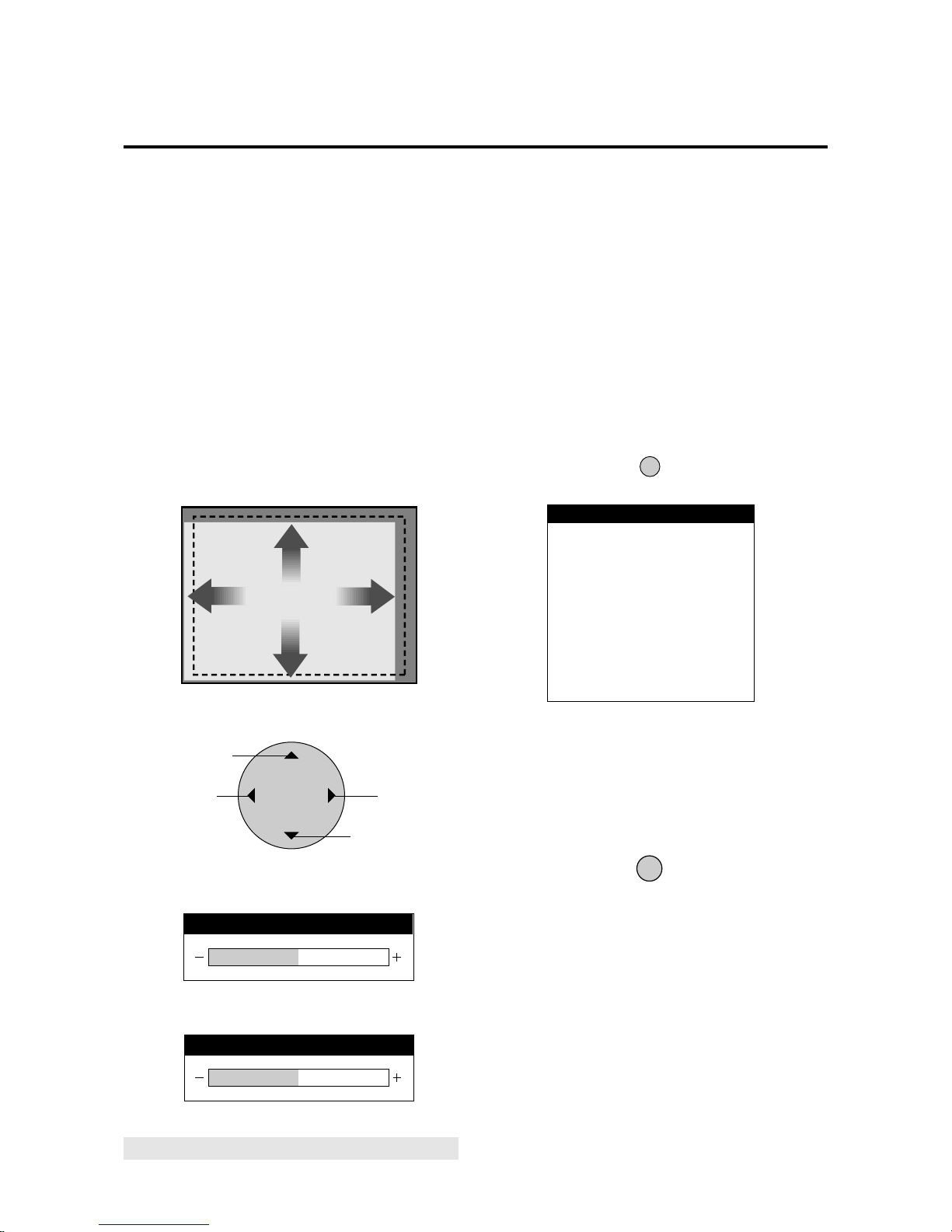
Press the buttons of the remote control to make direct adjustments and settings. A press of the desired button will
show the adjustment display. The adjustment condition is
stored in memory even after the power is switched off.
Preparation: Select the input screen (VIDEO, RGB1,
RGB2, RGB3) that is to be adjusted, after the input signal
is connected.
Adjustment of the Screen
The adjustment of screen size is made easier when a geometric shape such as a square is displayed.
Press the button to show the adjustment display. The display will go off about 3 seconds after your finger is released from the button.
Adjustment of the screen display position
Adjustment display of the up/down position
Adjustment display of the left/right position
Move left
Move up
Move right
Move down
Returning the Screen Adjustment
to the Factory Default Settings
(NORMAL)
The display position (POSITION) will return to the factory default setting. At this time the following settings of
the menu control will also simultaneously return to the factory default settings: AUTO PICTURE, PICTURE ADJUST, FINE PICTURE, H/V-POSITION 1, H/V-POSITION 2, H-WIDTH (Multiple Screens only), V-HEIGHT
(Multiple Screens only) and OSM location.
2. A press of the PROCEED button will reset the
adjustment.
To cancel the reset, press the EXIT button.
* Use the RASTER NORMAL button. A press of the
VISUAL NORMAL button will not return the screen
adjustment to the factory default setting.
* A press of the NORMAL button during the on-screen
display will return only the display item to the factory
default setting.
* H-POSITION 1,2 and V-POSITION 1,2 are not avail-
able at the time of RGB input when AUTO PICTURE is
turned on.
To adjust H-POSITION 1,2 and V-POSITION 1,2 at the
time of RGB input, turn off AUTO PICTURE.
RASTER
NORMAL
PROCEED
ABOUT TO RESET
RASTER
PRESS:
'PROCEED' TO RESET
'EXIT' TO CANCEL
WARNING
V-POSITION
H-POSITION
▼MOVE DOWN
MOVE UP ▲
§
MOVE LEFT
MOVE RIGHT
©
1. Press the RASTER NORMAL button
The verification sub menu is displayed.
NOTE:
See page 28 on how to adjust the H/V-Positions.
Page 21
E-22
Adjustment of the Image
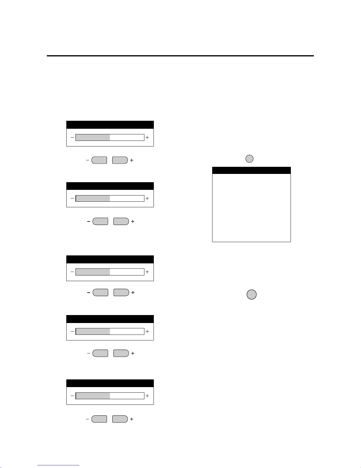
Press the button to show the adjustment display . The display
will go off about 3 seconds after your finger is released
from the button.
Items adjusted with the VIDEO screen and RGB signals
Contrast adjustment (CONTRAST)
CONTRAST
Brightness adjustment (BRIGHTNESS)
BRIGHT
Color density adjustment
COLOR
VIDEO
Tint adjustment
TINT
Sharpness adjustment (SHARPNESS)
SHARPNESS
Image becomes fainter
Image becomes denser
Screen becomes darker Screen becomes brighter
Items adjusted with only VIDEO signals
Color becomes lighter Color becomes deeper
Screen is tinted toward red Screen is tinted toward green
Softer quality Sharper quality
VISUAL
NORMAL
Returning the Image Adjustments to the Factory Default
Settings (NORMAL)
The contrast, brightness, color, tint, gamma, color temp
and sharpness adjustments can be returned to the factory
default settings. At this time , White Balance of the menu
control will simultaneously return to the factory default
setting.
1. Press the VISUAL NORMAL button
The verification sub menu is displayed.
2. A press of the PROCEED button will reset the
adjustment.
To cancel the reset, press the EXIT button.
* Use the VISUAL NORMAL button. A press of the
RASTER NORMAL button will not return the screen
adjustment to the factory default setting.
* A press of the NORMAL button during the on-screen
display will return only the display item to the factory
default setting.
PROCEED
CONTRAST
BRIGHTNESS
COLOR
TINT
SHARPNESS
ABOUT TO RESET
VISUAL
PRESS:
'PROCEED' TO RESET
'EXIT' TO CANCEL
WARNING
Page 22
E-23
Adjustment of the Display (Menu Control)
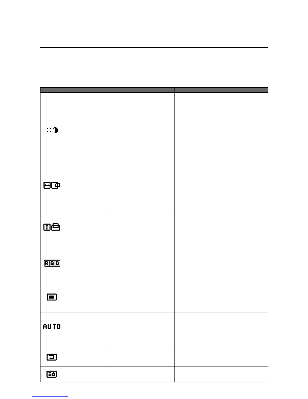
Use of the on-screen display (OSM) function allows the setting of various fine adjustments to be made. The adjustment
details will be stored even when the power is switched off.
The on-screen display (OSM) function puts an adjustment display onto the screen and adjustments are made while viewing
this display.
List of Setting Details
Icon On-screen menu Sub menu Adjustment details
Visual Control
Image adjustment (The display will differ between video
input selection and RGB input selection.)
Brightness adjustment
Contrast adjustment
Adjustment of the saturation of the colors
Tint adjustment
Sharpness adjustment
Adjustment of the gamma characteristics
(Adjusts the brightness of dark portions)
Brightness adjustment
Contrast adjustment
Adjustment of the gamma characteristics
(Adjusts the brightness of dark portions)
At time of video input selection
Brightness
Contrast
Color
Tint
Sharpness
Gamma
At time of RGB input selection
Brightness
Contrast
Gamma
H-Position
H-Position 1
H-Position 2
H-Width
Horizontal position 1
Used to align the raster on the PDP
Horizontal position 2
Only needs to be adjusted when H-Position 1 does
not allow the complete image to fill the screen. (Ad-
justment is not required with a standard signal.)
Horizontal enlargement ratio adjustment (Only for
Multiple Screens)
V-Position V-Position 1
V-Position 2
V-Height
Vertical position 1
Used to align the raster on the PDP
Vertical position 2
Only needs to be adjusted when V-Position 1 does
not allow the complete image to fill the screen. (Ad-
justment is not required with a standard signal.)
Vertical enlargement ratio adjustment (Only for Multiple Screens)
Color Temp Color temperature adjustment
High
Low
White balance adjustment
White balance adjustment of bright images (high brightness)
White balance adjustment of dark images (dark colors)
High
Low
At time of USER selection
Gain
Bias
OSM Location On-screen adjustment
On-screen horizontal position adjustment
On-screen vertical position adjustment
On-screen angle setting (Horizontal and vertical display)
On-screen display OFF time setting
OSM H-Position
OSM V-P osition
OSM Angle
OSM Display Time
Auto Picture Auto Picture
INPUT MODE
RGB MODE
Picture ADJ
Fine Picture
WIDE MODE
Used to automatically adjust the clock frequency and
clock phase in personal computer screen adjustment.
Signal discrimination
RGB MODE setting
Clock frequency adjustment
Clock phase adjustment
WIDE MODE setting
Normal
All Visual Normal
All Raster Normal
All Normal
Visual setting reset
Raster setting reset
Visual/Raster setting reset
Next page
Page 23
E-24
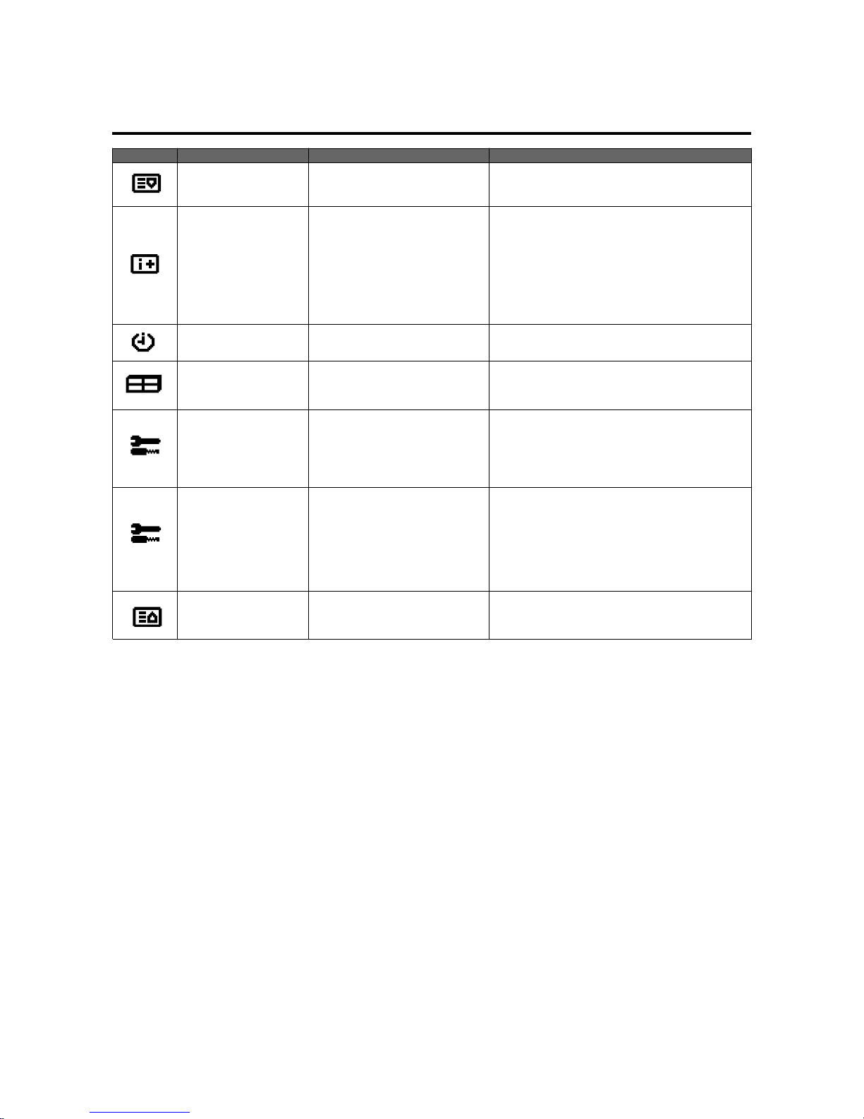
Display Mode Display mode display
Display source (VIDEO/RGB1,2,3)
Horizontal frequency (kHz)
Vertical frequency (Hz)
Polarity of horizontal sync
Neg./Pos. (Negative polarity/Positive polarity)
Polarity of vertical sync
Neg./Pos. (Negative polarity/Positive polarity)
Source Info:
H-Freq.:
V-Freq.:
H-Pol.:
V-Pol.:
Icon On-screen menu Sub menu Adjustment details
Long Life Mode 1
Long Life Mode 2
Long Life Mode 3
Gray Level
Set ID No.
RGB 3 ADJ
All Reset
Present Time Present Time
Timer ON/OFF time and mode settingTimer
VIDEO WALL Menu Multiple screens settings
Screen division setting
Screen division position setting
Screen Divider Setting
Position of Divider
Color System
Power On Mode
Power Manage
External Control
All Reset
Color system setting
Power ON mode setting
Power management setting
External control setting
Settings reset
Long life mode 1 setting
Long life mode 2 setting
Long life mode 3 setting
Gray level setting
Set ID number setting
Set when the image of RGB 3 is in disorder.
Settings reset
SETTINGS 1
SETTINGS 2
Previous page
Previous page
Page 24
E-25
BRIGHTNESS
CONTRAST
SHARPNESS
COLOR
TINT
GAMMA:2
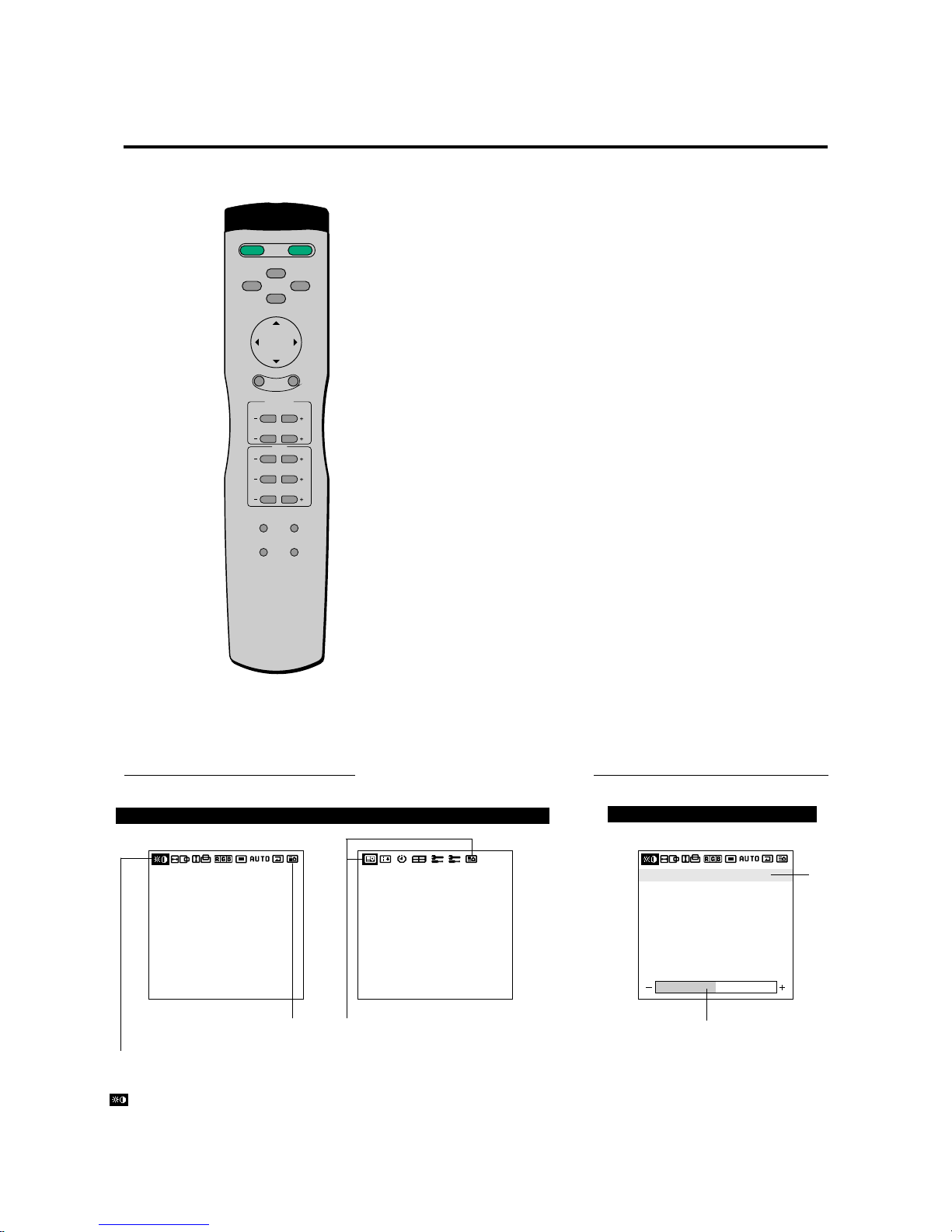
Before Making Adjustments...
Adjust using the remote control buttons.
PROCEED button
Press to display the main menu.
Press in the main menu to display the sub menu.
EXIT button
Press in the main menu to turn off the display and exit.
Press during the display of the sub menu to return to the
main menu.
POSITION/CONTROL ▲ / ▼ buttons
Moves the cursor up or down and selects the adjustment
item.
POSITION/CONTROL § / © buttons
Moves the cursor left or right and selects an icon. Press
during the display of the sub menu to increase or decrease
the adjustment value (and the bar will lengthen or shorten
in the positive (+) or negative (-) direction).
VISUAL NORMAL button or RASTER NORMAL
button
Resets the adjustment value of the selected item in the menu
display . (Values return to the factory default settings.) When
a menu is not being displayed, all of the screen adjustments
or all of the image adjustment items are reset. (There are
two types of NORMAL functions: one is “RASTER” for
screen adjustments and the other is “VISUAL” for image
adjustments.)
POWER
ON
POWER
OFF
RGB 1
RGB 2
POSITION / CONTROL
RGB 3
EXIT
PROCEED
VIDEO
CONTRAST
RGB/VIDEO
BRIGHT
COLOR
VIDEO
TINT
SHARPNESS
VISUAL
NORMAL
RASTER
NORMAL
ID SELECT CLEAR
Operation of the On-screen Display
Sub menu
BRIGHTNESS
CONTRAST
SHARPNESS
COLOR
TINT
GAMMA:2
SOURCE INFO.
RGB1
H-FREQ.
V-FREQ.
H-POL.
V-POL.
31.5kHz
60.0Hz
NEG
POS
Main menu
Display the next page Display the previous page
Display the adjustment value
Cursor
The items of the main menu are displayed as icons.
See Page E-23 for details.
While this icon is displaying, pressing the POSITION/CONTROL
§
button
allows you to go to the next page.
Page 25
E-26
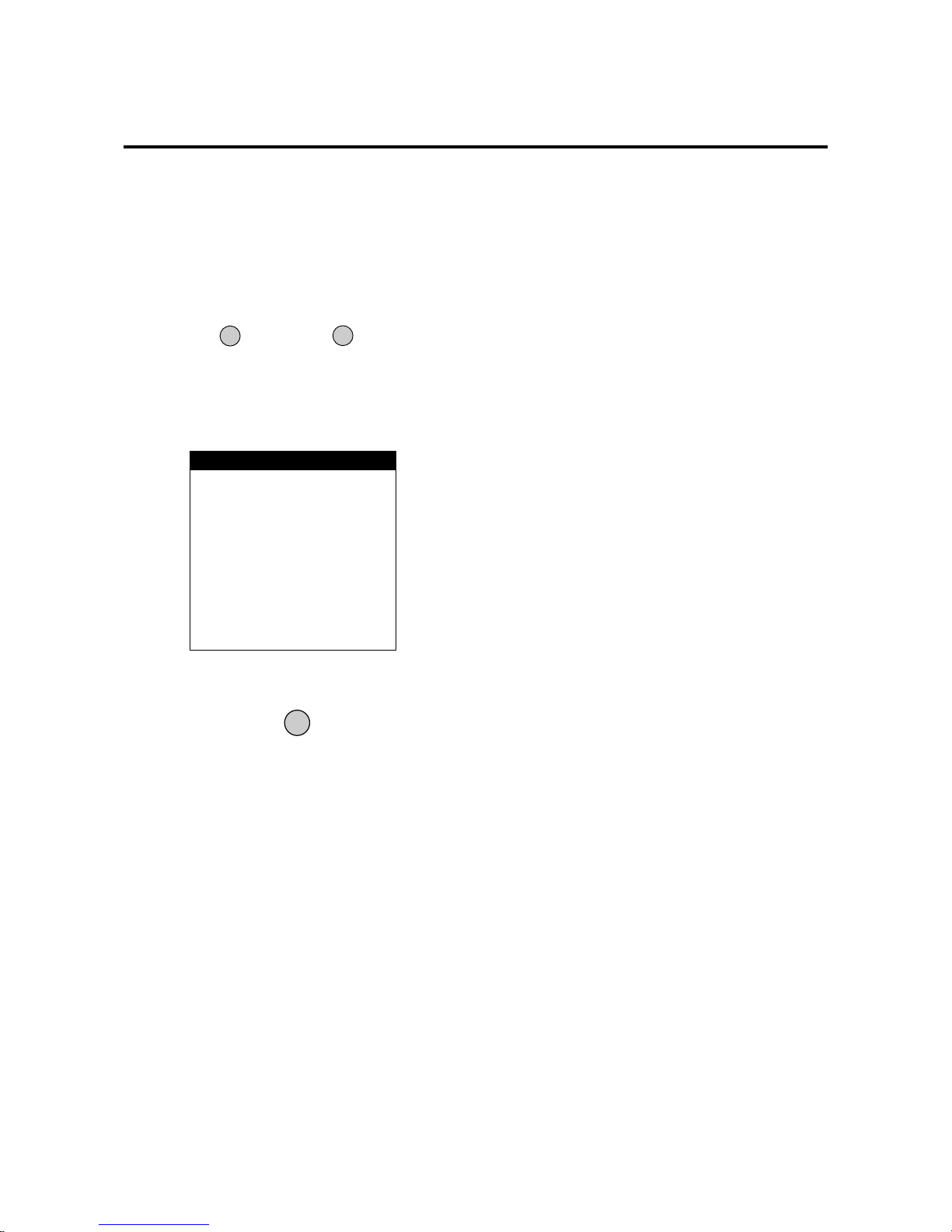
To Reset the Adjustment Value to
the Factory Default Setting
1. Press the VISUAL NORMAL button or RASTER
NORMAL button.
The verification sub menu is displayed.
VISUAL
NORMAL
PROCEED
2. A press of the PROCEED button will reset the
adjustment.
To cancel the reset, press the EXIT button.
ABOUT TO RESET
*****
PRESS:
'PROCEED' TO RESET
'EXIT' TO CANCEL
WARNING
RASTER
NORMAL
Automatic Storage
The settings values are stored automatically once the
PROCEED button is pressed.
Page 26
E-27
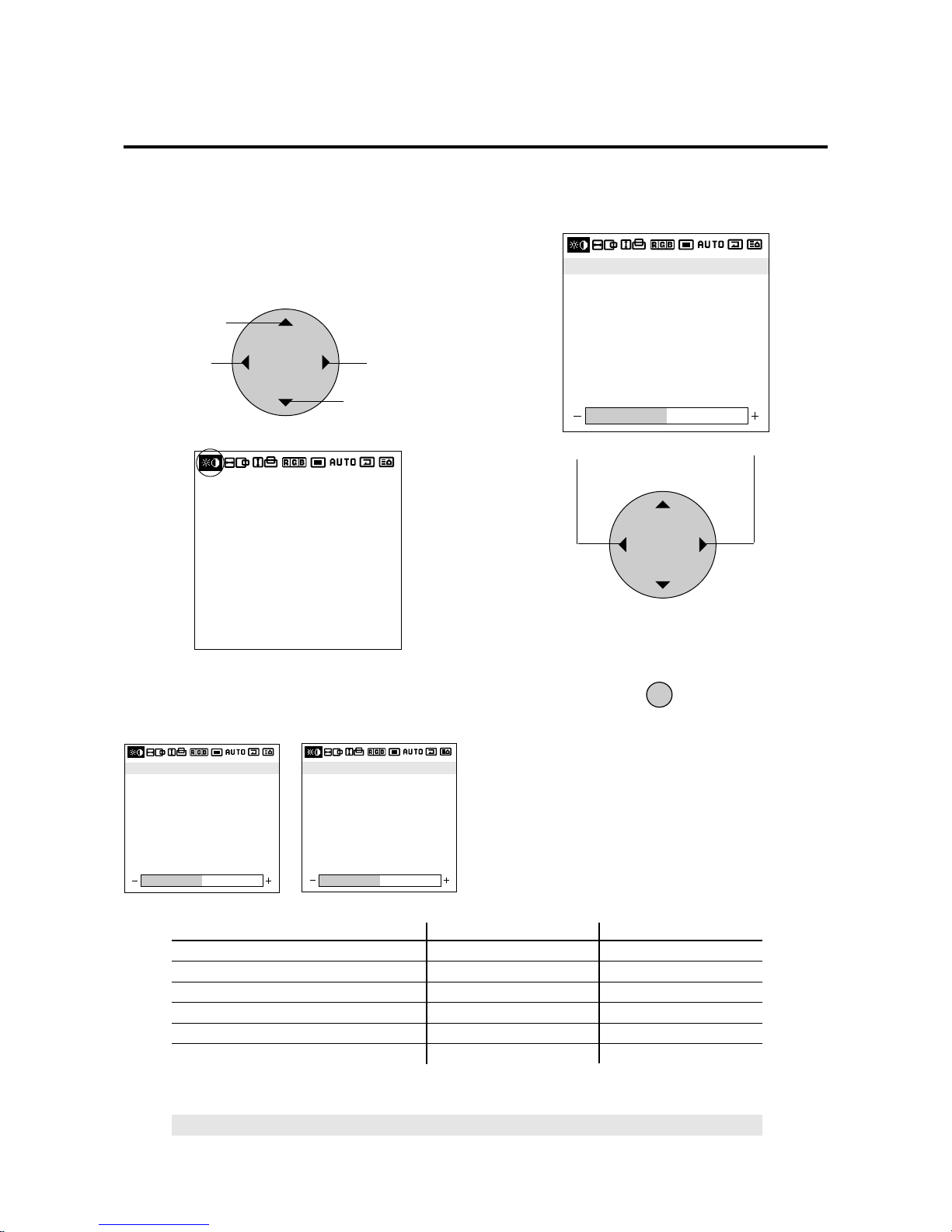
Adjustment of the Image (Visual Controls)
These controls adjust the brightness, contrast, color, tint,
and sharpness.
1. Align the cursor with icon (1).
Visual control screen
Icon (1)
The cursor is moved left and right with the POSITION
CONTROL § / © buttons.
2. Align the cursor with the desired item
At time of VIDEO selection
At time of RGB1/2/3 selection
3. While watching the screen, press the § / © buttons
and adjust
4. Return to the main menu
EXIT
* To reset the adjustment value, press the VISUAL
NORMAL button before pressing the EXIT button.
* T o delete the main menu, press the EXIT b utton once
more.
POSITION / CONTROL
Becomes weaker
Becomes stronger
Please use the table below as reference.
POSITION / CONTROL
Move left
Move up
Move right
Move down
BRIGHTNESS
CONTRAST
SHARPNESS
COLOR
TINT
GAMMA:2
BRIGHTNESS
CONTRAST
SHARPNESS
COLOR
TINT
GAMMA:2
BRIGHTNESS
CONTRAST
GAMMA : 2
The cursor is moved up and down with the POSITION
CONTROL ▲ / ▼ buttons.
BRIGHTNESS
CONTRAST
SHARPNESS
COLOR
TINT
GAMMA:2
Display (Adjustment details) Pressing the § button Pressing the © button
Brightness (Brightness adjustment) Screen becomes darker Screen becomes brighter
Contrast (Contrast adjustment) Image becomes fainter Image becomes denser
Color (Color saturation adjustment) Color becomes less saturated Color becomes more saturated
Tint* (Tint) Screen is tinted toward red Screen is tinted toward green
Sharpness (Sharpness adjustment) Softer quality Sharper quality
Gamma (Adjusts the brightness of dark portions) Normal Darker
Note:
When dark portions appear rough, adjust Gamma to provide an easy-to-view image.
*Tint cannot be adjusted when the video system selection switch is set to PAL or SECAM.
*Switching to GAMMA is not possible when LONG LIFE MODE3 is set to INV or WT.
Page 27
E-28
* To reset the adjustment value, press the RASTER
NORMAL button before pressing the EXIT button.
* T o delete the main menu, press the EXIT b utton once
more.
* H-POSITION 1,2 and V-POSITION 1,2 are not
available at the time of RGB input when AUTO PICTURE is turned on.
To adjust H-POSITION 1,2 and V-POSITION 1,2 at
the time of RGB input, turn off AUTO PICTURE.
* Horizontal and Vertical Position Controls
Both the horizontal and vertical position controls in
the OSM include a POSITION 1 and a POSITION 2
adjustment when an RGB signal is selected for
display. These two position controls provide access
to the entire raster position (POSITION 1) and a fine
adjustment within the raster (POSITION 2). First
adjust POSITION 1 so that the raster fills the entire
screen. After the raster position is set properly, then
select POSITION 2 to make sure that the image fills
the raster and all of the image is filling the screen.
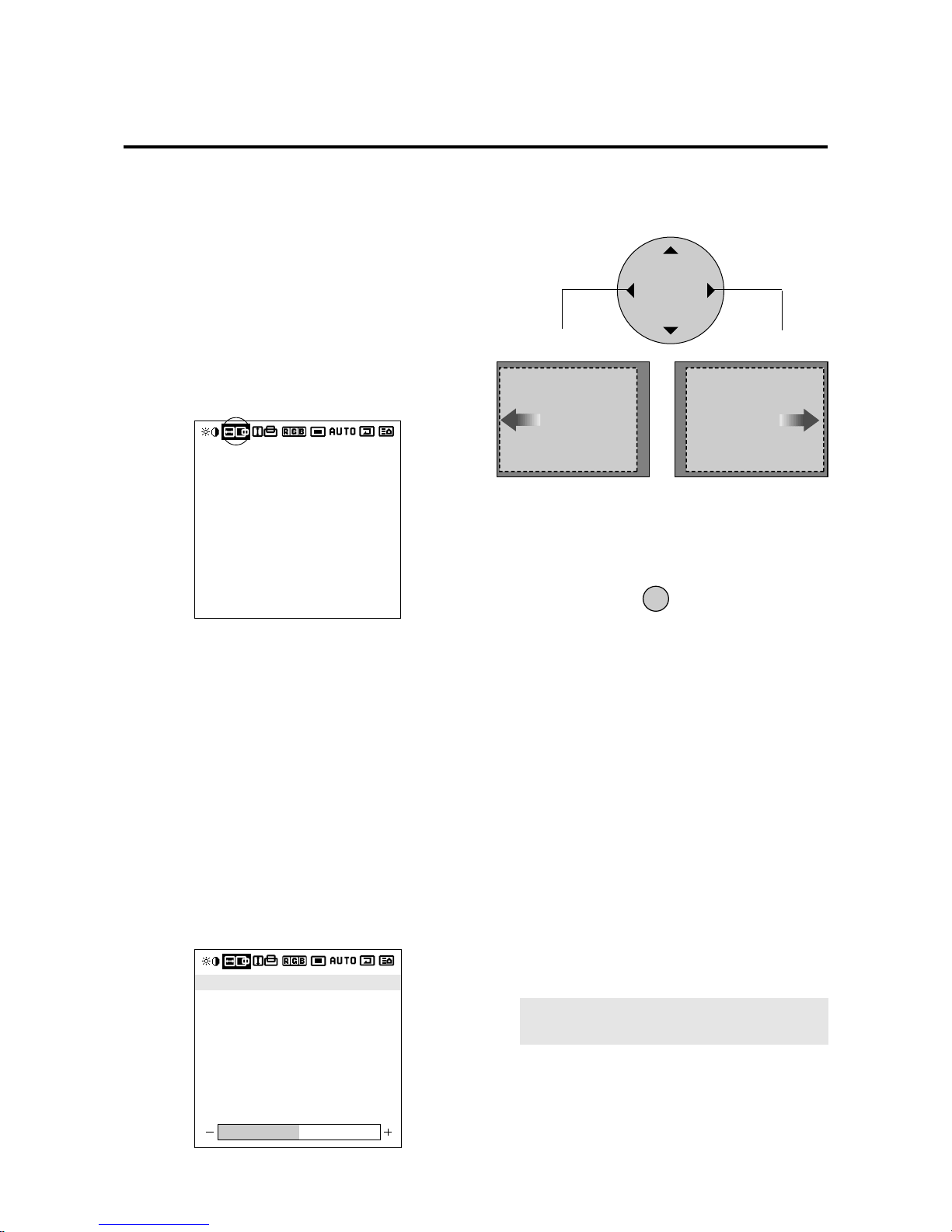
Adjustment of Screen Position (Horizontal)
Horizontal (H) Adjustment Screen
1. Align the cursor with icon (2)
Horizontal (H) adjustment screen
2. Align the cursor with the desired item
The cursor is moved left and right with the POSITION
CONTROL§ / © buttons.
The cursor is moved up and down with the POSITION
CONTROL ▲ / ▼ buttons.
H-WIDTH: Horizontal enlargement ratio adjustment
(Displayed only with Multiple Screens)
Adjustment is possible only in multi mode.
H-POSITION 2 cannot be adjusted at the time of
VIDEO input.
H-POSITION 1: Horizontal position 1
Used to align the raster on the PDP.
H-POSITION 2: Horizontal position 2
Only needs to be adjusted when H-Position 1 does not
allow the complete image to fill the screen.
(Adjustment is not required with a standard signal.)
H-WIDTH: Horizontal enlargement ratio adjustment
(Displayed only with Multiple Screens)
Adjustment is possible only in multi mode.
H-POSITION 2 cannot be adjusted at the time of
VIDEO input.
3. While watching the screen, press the § / © buttons
and adjust
POSITION / CONTROL
4. Return to the main menu
EXIT
H-POSITION 1
H-POSITION 2
H-WIDTH
Icon (2)
H-POSITION 1
H-POSITION 2
H-WIDTH
§
MOVE LEFT MOVE RIGHT
©
NOTE:
Make sure that none of the actual image is
missing, left to right or top to bottom.
Page 28
E-29
* To reset the adjustment value, press the RASTER
NORMAL button before pressing the EXIT button.
* To delete the main menu, press the EXIT button once
more.
* POSITION 1,2 and V-POSITION 1,2 are not avail-
able at the time of RGB input when AUTO PICTURE is turned on.
To adjust H-POSITION 1,2 and V-POSITION 1,2 at
the time of RGB input, turn off AUTO PICTURE.
* Horizontal and Vertical Position Controls
Both the horizontal and vertical position controls in
the OSM include a POSITION 1 and a POSITION 2
adjustment when an RGB signal is selected for
display. These two position controls provide access
to the entire raster position (POSITION 1) and a fine
adjustment within the raster (POSITION 2). First
adjust POSITION 1 so that the raster fills the entire
screen. After the raster position is set properly, then
select POSITION 2 to make sure that the image fills
the raster and all of the image is filling the screen.
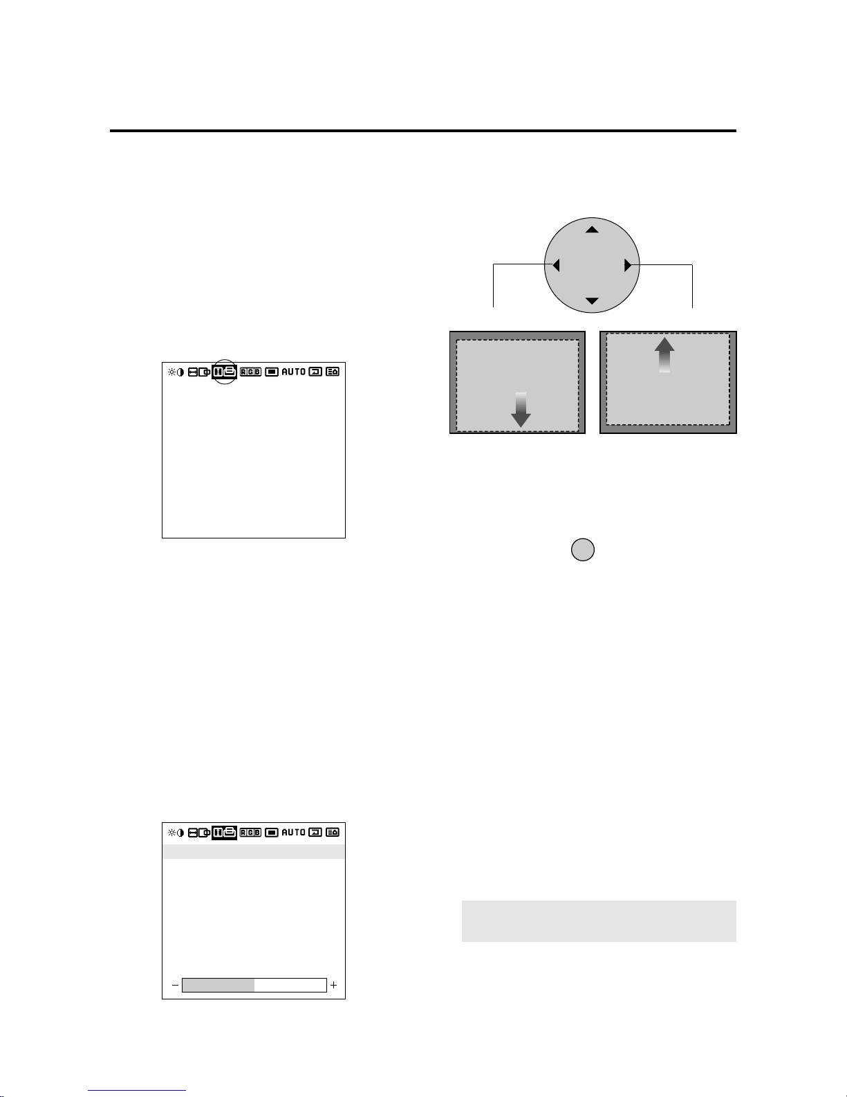
Adjustment of Screen Position (Vertical)
Vertical (V) Adjustment Screen
1. Align the cursor with icon (3)
Vertical (V) adjustment screen
Icon (3)
2. Align the cursor with the desired item
The cursor is moved left and right with the POSITION
CONTROL§ / © buttons.
The cursor is moved up and down with the POSITION
CONTROL ▲ / ▼ buttons.
V-HEIGHT: Vertical enlargement ratio adjustment
(Displayed only with Multiple Screens)
Adjustment is possible only in multi mode.
V-POSITION 2 cannot be adjusted at the time of
VIDEO input.
V-POSITION 1: Vertical position 1
Used to align the raster on the PDP.
V-POSITION 2: Vertical position 2
Only needs to be adjusted when V-Position 1 does not
allow the complete image to fill the screen.
(Adjustment is not required with a standard signal.)
V -HEIGHT: Vertical enlargement ratio adjustment (Displayed only with Multiple Screens)
Adjustment is possible only in multi mode.
V-POSITION 2 cannot be adjusted at the time of
VIDEO input.
3. While watching the screen, press the § / © buttons
and adjust
POSITION / CONTROL
4. Return to the main menu
EXIT
V-POSITION 1
V-POSITION 2
V-HEIGHT
V-POSITION 1
V-POSITION 2
V-HEIGHT
§
MOVE DOWN
MOVE UP
©
NOTE:
Make sure that none of the actual image is
missing, left to right or top to bottom.
Page 29
E-30
* To reset the adjustment value, press the VISUAL
NORMAL button before pressing the EXIT button.
* T o delete the main menu, press the EXIT b utton once
more.
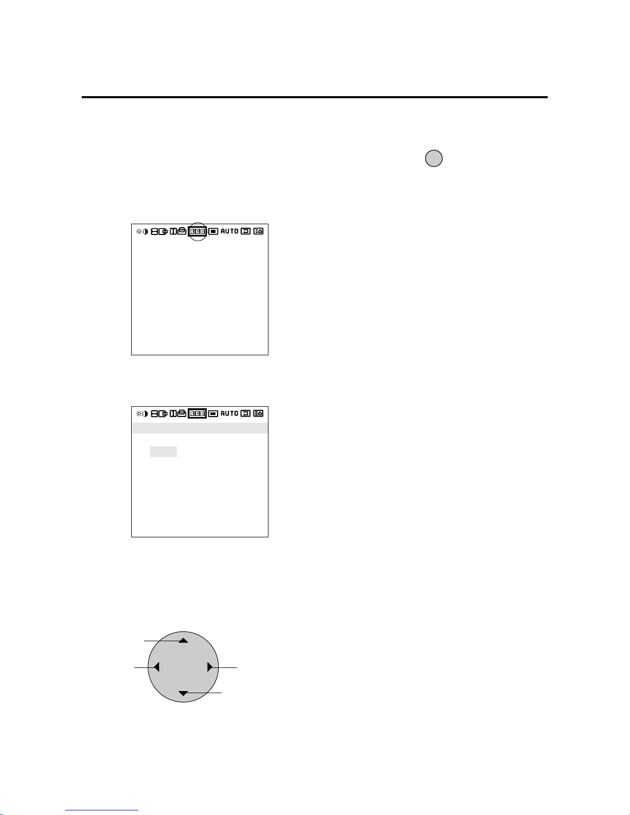
Color T emperature (COLOR TEMP)
This adjusts the color temperature.
1. Align the cursor with icon (4)
Color temperature adjustment screen
Icon (4)
2. Align the cursor with COLOR TEMP and set with
the § / © buttons.
The cursor is moved left and right with the POSITION
CONTROL§ / © buttons.
3. Return to the main menu
EXIT
Color temperature adjustment
HIGH : High
LOW : Low
USER : User setting
POSITION / CONTROL
Move left
Move up
Move right
Move down
COLOR TEMP
COLOR TEMP
HIGH LOW USER
Page 30
E-31
* To reset the adjustment value, press the VISUAL
NORMAL button before pressing the EXIT button.
* T o delete the main menu, press the EXIT b utton once
more.
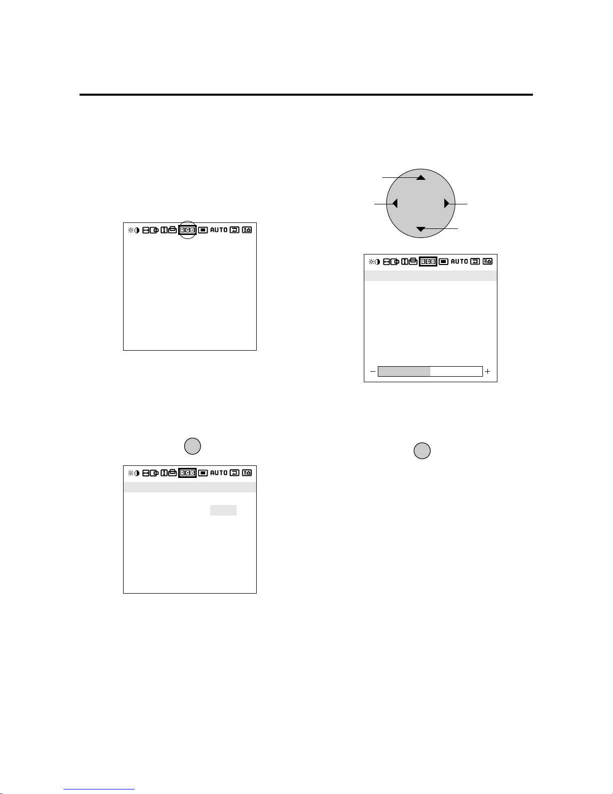
Adjustment of the White Balance
This adjusts the white balance of bright images (Gain) and
dark images (Bias).
1. Align the cursor with icon (4)
Icon (4)
2. After selecting COLOR TEMP , align the cur sor with
USER and press the PROCEED button.
The cursor is moved left and right with the POSITION
CONTROL§ / © buttons.
4. Return to the main menu
EXIT
POSITION / CONTROL
Becomes weaker
Move up
Becomes stronger
Move down
The cursor is moved left and right with the POSITION
CONTROL § / © buttons.
3. Align the cursor with Gain or Bias of the sub menu,
then make the adjustment with the § / © buttons
while watching the screen.
PROCEED
Color temperature adjustment screen
R-GAIN (WHITE LEVEL)
G-GAIN (WHITE LEVEL)
B-GAIN (WHITE LEVEL)
R-BIAS (BLACK LEVEL)
G-BIAS (BLACK LEVEL)
B-BIAS (BLACK LEVEL)
COLOR TEMP
HIGH LOW USER
PRESS 'PROCEED' FOR
GAIN / BIAS
SETTING
COLOR TEMP
Page 31
E-32
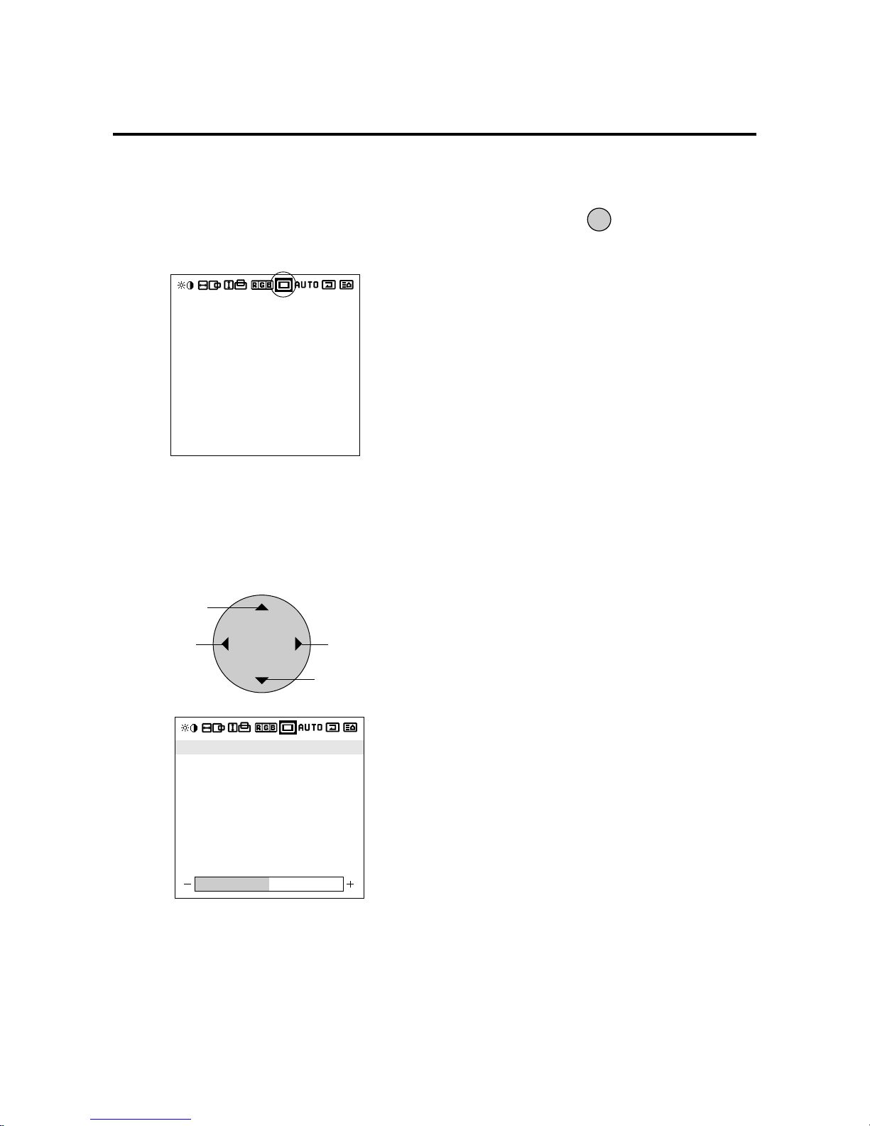
OSM adjustment screen
* The change will be stored when the menu is deleted.
To reset the adjustment value, press the RASTER
NORMAL button before pressing the EXIT button.
* To adjust another item, press the EXIT button.
Adjustment of the On-screen Display Position
1. Align the cursor with icon (5)
3. Exiting the adjustment
EXIT
POSITION / CONTROL
DOWN/LEFT
Move up
UP/RIGHT
Move down
The cursor is moved left and right with the POSITION
CONTROL§ / © buttons.
2. Align the cursor with the desired item from the sub
menu and adjust.
Icon (5)
The OSM screen can be rotated 90º counterclockwise
for easy viewing in portrait mode by changing the OSM
ANGLE on the menu.
The display will change to the main menu.
Another press of the button will delete the main menu
and exit the adjustment.
OSM H-POS
OSM V-POS
OSM ANGLE
OSM DISPLAY TIME
OSM H-POS
OSM V-POS
OSM ANGLE
OSM DISPLAY TIME
The cursor is moved up and down with the POSITION
CONTROL ▲ / ▼ buttons.
Page 32
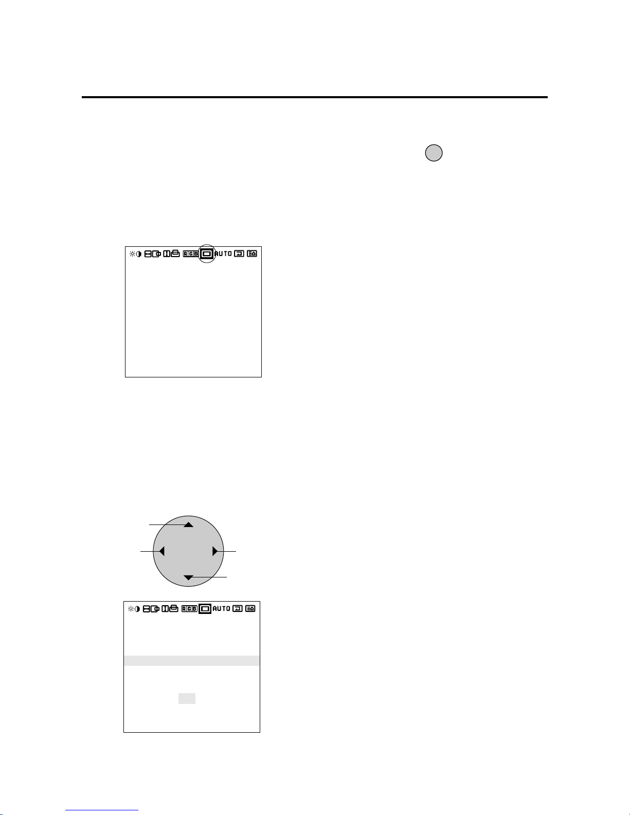
E-33
Setting the On-screen Display OFF Time
While using the on-screen display (OSM), the OFF time
setting functions to automatically turn off the on-screen
display when there is no input.
1. Align the cursor with icon (5)
2. Align the cursor with OSM DISPLAY TIME of the
sub menu and select the desired time
EXIT
POSITION / CONTROL
Changes to a
shorter OFF time
Move up
Changes to a
longer OFF time
Move down
Align with the inverted characters.
The following can be selected: 5 seconds, 10 seconds,
30 seconds, 60 seconds, and 120 seconds.
3. Return to the main menu
The cursor is moved left and right with the POSITION
CONTROL§ / © buttons.
OSM adjustment screen
Icon (5)
* The factory default setting is 30 seconds.
* To delete the main menu, press the EXIT button once
more.
OSM H-POS
OSM V-POS
OSM ANGLE
OSM DISPLAY TIME
OSM H-POS
OSM V-POS
OSM ANGLE
OSM DISPLAY TIME
SECONDS :
5 10 30 60 120
Page 33
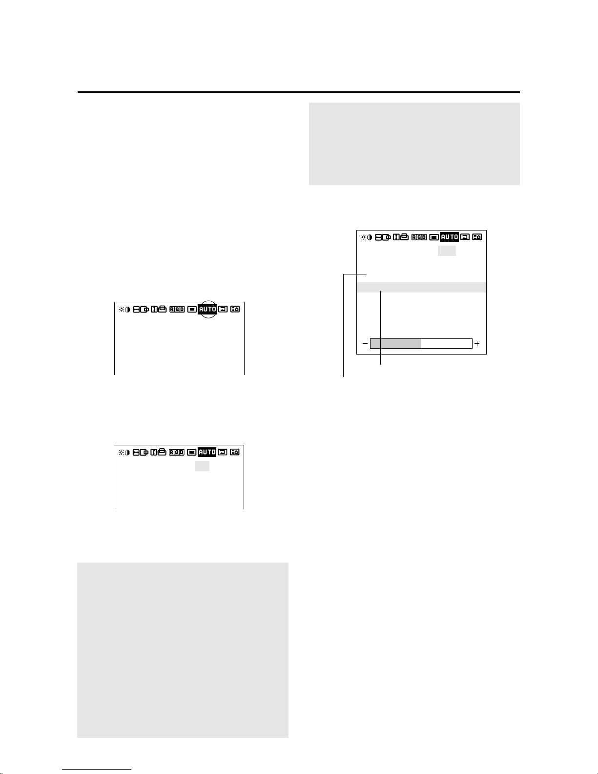
E-34
Adjustment of the Clock Frequency/Clock Phase
(AUTO PICTURE)
When AUTO PICTURE is set to ON, normally the clock
frequency adjustment and the clock phase adjustment are not
necessary, but this adjustment should be made w hen the automatic adjustment cannot be made correctly.
Make the adjustment when a new signal has been input, when
vertical lines appear blurry , or if the image appears unclear.
H-POSITION 1,2 and V-POSITION 1,2 are not available at
the time of RGB input when AUTO PICTURE is turned on.
To adjust H-POSITION 1,2 and V-POSITION 1,2 at the
time of RGB input, turn off AUTO PICTURE.
1. Align the cursor with icon (6)
2. Align the cursor with A UTO PICTURE and set to OFF.
AUTO PICTURE: Automatically adjusts the screen
position, clock frequency, and clock phase when ON.
* The cursor is moved up and down with the POSITION
CONTROL ▲ / ▼ buttons.
3. Align the cursor with the desired item using the
POSITION CONTROL § /
© buttons
.
The cursor is moved left and right with the POSITION
CONTROL§ / © buttons.
AUTO PICTURE: ON/OFF
Select with POSITION CONTROL § / © buttons.
There is a transition to the screen below only when OFF.
Note:
•The Picture ADJ and Fine Picture features are
available only when the Auto Picture is off. The Picture
ADJ and Fine Picture features are not available for
Video or S-Video source.
•When the Auto Picture is on, the Picture ADJ and Fine
Picture adjustments are made automatically.
•The Picture Adjustment control allows you to fine tune
the computer image or to remove vertical banding that
might appear. This function adjusts the clock
frequencies that eliminate banding in the image.
•The Fine Picture adjusts the clock phase or reduces
video noise, dot interference or cross talk. (This is
evident when parts of the image appear to be
shimmering.) The Fine Picture adjustment may be
Selecting Native Resolutions for 848 x 480, 852 x 480
and 640 x 480 input signals
There are two controls in the Plasma monitor OSM menus
that allow you to set the monitor to display resolutions
with 848, 852 and 640 horizontal dots in their true
resolutions.
When inputting an 848 x 480 signal, align the cursor at the
top of the OSM window. Move the cursor down to WIDE
MODE and use the POSITION LEFT/RIGHT control to
select 4 x 3. The monitor will display the signal at 848 x
480. If FULL is selected, the monitor will automatically
expand the input signal to 853 x 480.
To choose between 640 x 480 and 852 x 480 resolutions
align the cursor with icon 6 (auto) at the top of the OSM
window, move the cursor down to INPUT MODE and...
Use the POSITION LEFT/RIGHT control to select 16 x 9
to display 852 x 480 in true resolution or to expand
(stretch) 640 x 480 to fill the screen from left to right.
Select 4 x 3 to display 640 x 480 resolution in its standard
4:3 aspect ratio with vertical letterbox bars to the right and
left of the image.
After selecting the desired setting, go to the Auto menu,
set auto picture to OFF and use the Picture Adjust and
Fine Picture controls to adjust clock phase and frequency
to sharpen the image, if necessary.
INPUT MODE: 4 X 3 / 16 X 9
Select with the POSITION CONTROL § / © buttons.
AUTO PICTURE : OFF
INPUT MODE
RGB MODE
PICTURE ADJ
FINE PICTURE
WIDE MODE
: 4X3
: STILL
: NORMAL
Clock frequency adjustment
Clock phase adjustment
necessary when you connect your computer for the first
time and you have a blurred picture on the screen.
•If the displayed image is small with respect to the
original number of horizontal pixels (including cases
when the display area/lit area is small) when AUTO
PICTURE is turned on, it may take up to 6 seconds for
the image to be displayed.
AUTO PICTURE : ON
INPUT MODE
RGB MODE
: 4
X
3
: STILL
AUTO PICTURE adjustment screen
Icon (6)
AUTO PICTURE : ON
INPUT MODE
RGB MODE
: 4X3
: STILL
Page 34
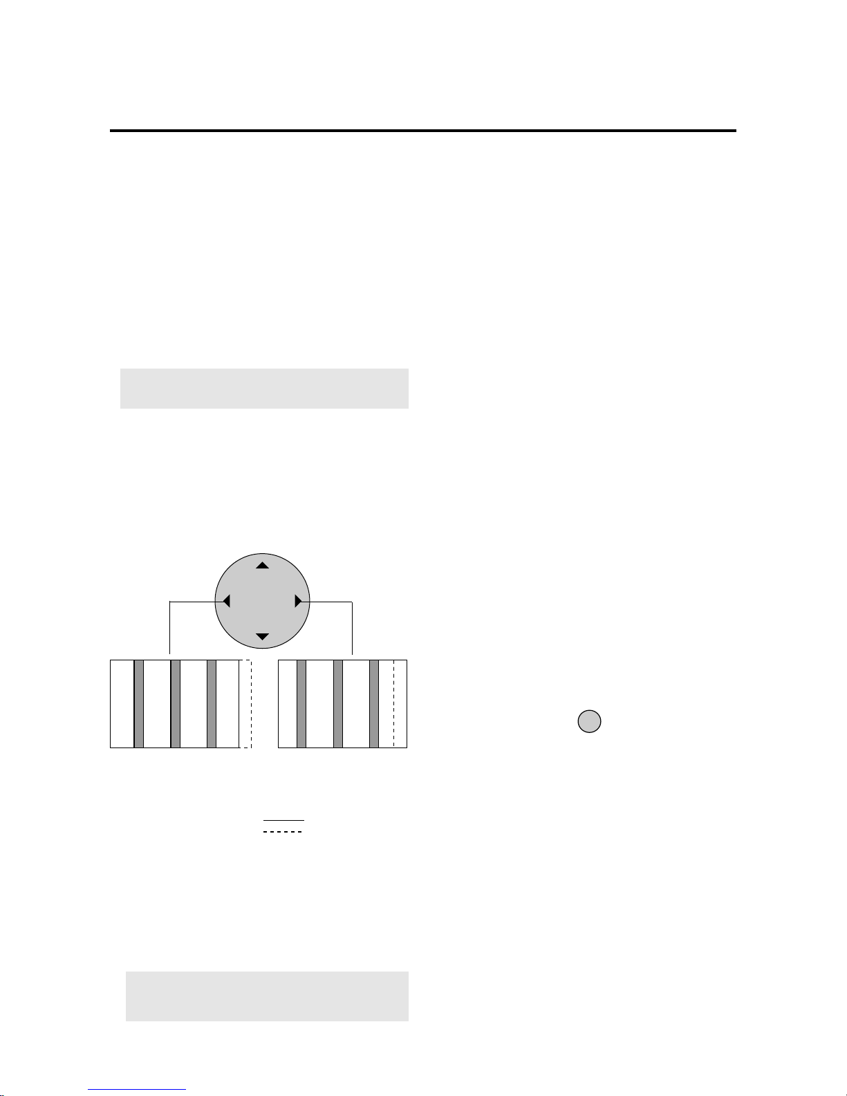
E-35
* Clock phase adjustment (Fine Picture)
Adjust the phase of the clock and adjust the (+) and (-)
buttons so that screen noise, flicker, and color inf idelity
are minimized. First adjust the clock frequency, then
perform the clock phase adjustment.
Note:
Neither the clock frequency adjustment nor
the clock phase adjustment function are available at
the time of VIDEO and S-VIDEO input.
5. Return to the main menu
* To reset the adjustment value, press the RASTER
NORMAL button before pressing the EXIT button.
* To delete the main menu, press the EXIT button once
more.
EXIT
4. Make the various adjustments with the POSITION
CONTROL § / © buttons.
* Clock frequency adjustment (Picture ADJ)
Adjust the clock frequency and adjust the width of
the image with respect to the screen.
The adjustment is made with a dot unit signal. Adjust
to the position at which vertical flickering disappears.
Screen display range
Image range width
POSITION / CONTROL
Go to operation 2 when continuing the adjustment
When image width is wide (i.e.,
clock frequency is high), narrow
the width with the (-) button.
When image width is narrow
(i.e., clock frequency is low),
widen the width with the (+)
button.
* RGB MODE:
RGB MODE is displayed at the time of RGB input, RGB
MODE is not displayed at the time of video input.
Initial value : STILL
This is used in signal discrimination at the time of RGB
input.
Note:
When a moving picture is displayed in still
picture mode, the screen will appear blurry.
At time of RGB input
[MOTION]: Set when a scan converter or other mov-
ing picture has been connected
[STILL]: Set when displaying a personal computer
screen
[DTV]: Set when using digital broadcast or other
sources with an RGB input
* WIDE MODE:
NORMAL/FULL/ST ADIUM/ZOOM (Initial v alue: NORMAL)
Note that only NORMAL/FULL area available in RGB
mode.
Selecting Native Resolutions for 848 x 480, 852 x 480 and
640 x 480 input signals
There are two controls in the Plasma monitor OSM menus
that allow you to set the monitor to display resolutions with
848, 852 and 640 horizontal dots in their true resolutions.
When inputting an 848 x 480 signal, align the cursor at the
Bottom of the OSM window. Move the cursor down to
WIDE MODE and use the POSITION LEFT/RIGHT
control to select NORMAL. The monitor will display the
signal at 848 x 480. If FULL is selected, the monitor will
automatically expand the input signal to 853 x 480.
To choose between 640 x 480 and 852 x 480 resolutions
align the cursor with icon 6 (auto) at the top of the OSM
window, move the cursor down to INPUT MODE and...
Use the POSITION LEFT/RIGHT control to select 16 x 9 to
display 852 x 480 in true resolution or to expand (stretch)
640 x 480 to fill the screen from left to right. Select 4 x 3 to
display 640 x 480 resolution in its standard 4:3 aspect ratio
with vertical letterbox bars to the right and left of the image.
After selecting the desired setting, go to the Auto menu, set
auto picture to OFF and use the Picture Adjust and Fine
Picture controls to adjust clock phase and frequency to
sharpen the image, if necessary.
Page 35
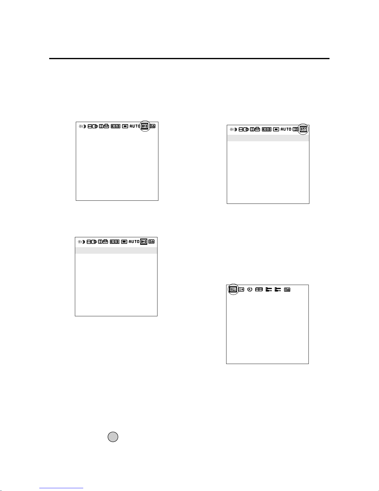
E-36
EXIT
3. Return to the main menu
* To delete the main menu, press the EXIT b utton once
more.
Next Page Screen
1. Moving the cursor to the next page icon (8) at the
right edge of the screen will move the display to the
second page.
The cursor is moved left and right with the POSITION
CONTROL§ / © buttons.
Icon (8)
ALL VISUAL NORMAL
ALL RASTER NORMAL
ALL NORMAL
PROCEED TO RESET
Previous Page Screen
Icon (9)
SOURCE INFO.
RGB1
H-FREQ.
V-FREQ.
H-POL.
V-POL.
31.5kHz
60.0Hz
NEG
POS
Previous Page Screen
1. Align the cursor with icon (9) at the very top to move
to the first page menu screen.
The cursor is moved left and right with the POSITION
CONTROL§ / © buttons.
Normal Screen
Returns the user side image data of the mode currently
being input to the standard condition.
1.Align the cursor with icon (7)
2. Align the cursor with the desired item and press the
PROCEED button.
The cursor is moved left and right with the POSITION
CONTROL§ / © buttons.
Icon (7)
The cursor is moved up and down with the POSITION
CONTROL▲ / ▼ buttons.
ALL RASTER NORMAL
* Initialization items
H-POSI 1,2, V-POSI 1,2, AUTO PICTURE, OSM
POSITION.
* The following items are added in multi mode:
Screen switching position, horizontal/vertical enlargement ratio (H/V WIDTH)
ALL VISUAL NORMAL
Color, tint, sharpness, contrast, brightness, color temperature, gamma.
ALL VISUAL NORMAL
ALL RASTER NORMAL
ALL NORMAL
ALL VISUAL NORMAL
ALL RASTER NORMAL
ALL NORMAL
PROCEED TO RESET
Page 36
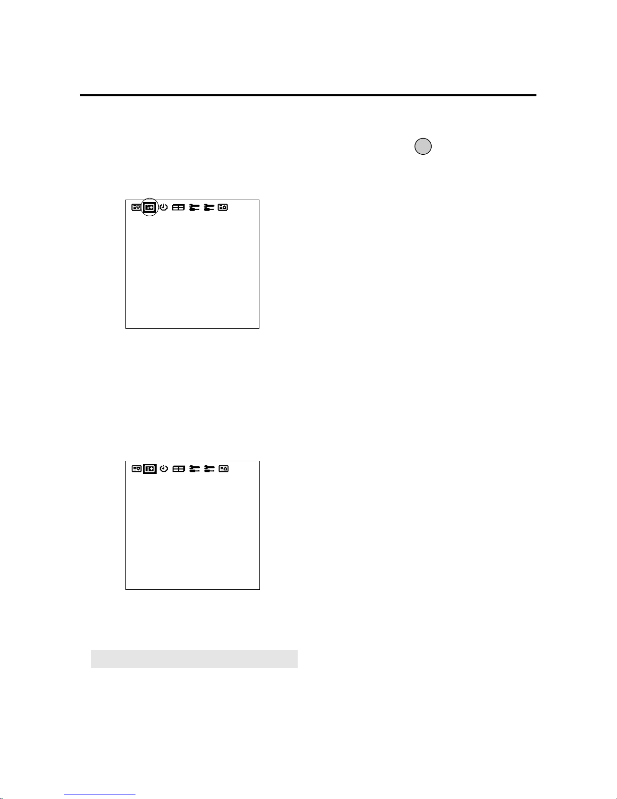
E-37
Information Screen
This permits a check on-screen of the resolution and data
of the signal that is currently being input.
1. Align the cursor with icon (10) on the second page of
the main menu and display the display mode.
* When video input is selected
SOURCE: VIDEO
MODE: NTSC, PAL, SECAM
Note:
NTSCis processed as 4.43 NTSC.
Icon (10)
Information screen
* When RGB input is selected
SOURCE: RGB1, RGB2, RGB3
“NO SIGNAL” is displayed when there is no signal.
H-FREQ: Horizontal frequency (kHz)
V-FREQ: Vertical frequency (Hz)
H-POL: Polarity of the horizontal sync signal
Neg./Pos. (Negative polarity/Positive polarity)
V-Pol.:Polarity of vertical sync
Neg./Pos. (Negative polarity/Positive polarity)
2. Return to the main menu
* Settings cannot be reset.
* To delete the main menu, press the EXIT button once
more.
* The vertical frequency that is displayed in the display
mode can have a slight difference with respect to the
actual vertical frequency of the connected input signal. Vertical signals of between 60 Hz and 70 Hz have
an error of plus/minus 3 Hz. Vertical signals of 70 Hz
or greater have an error of plus/minus 5 Hz. The frequency display of the display mode via the OSM system should always be regarded as a guideline.
EXIT
SOURCE INFO.
RGB1
H-FREQ.
V-FREQ.
H-POL.
V-POL.
31.5kHz
60.0Hz
NEG
POS
SOURCE INFO.
VIDEO
MODE : NTSC
Page 37
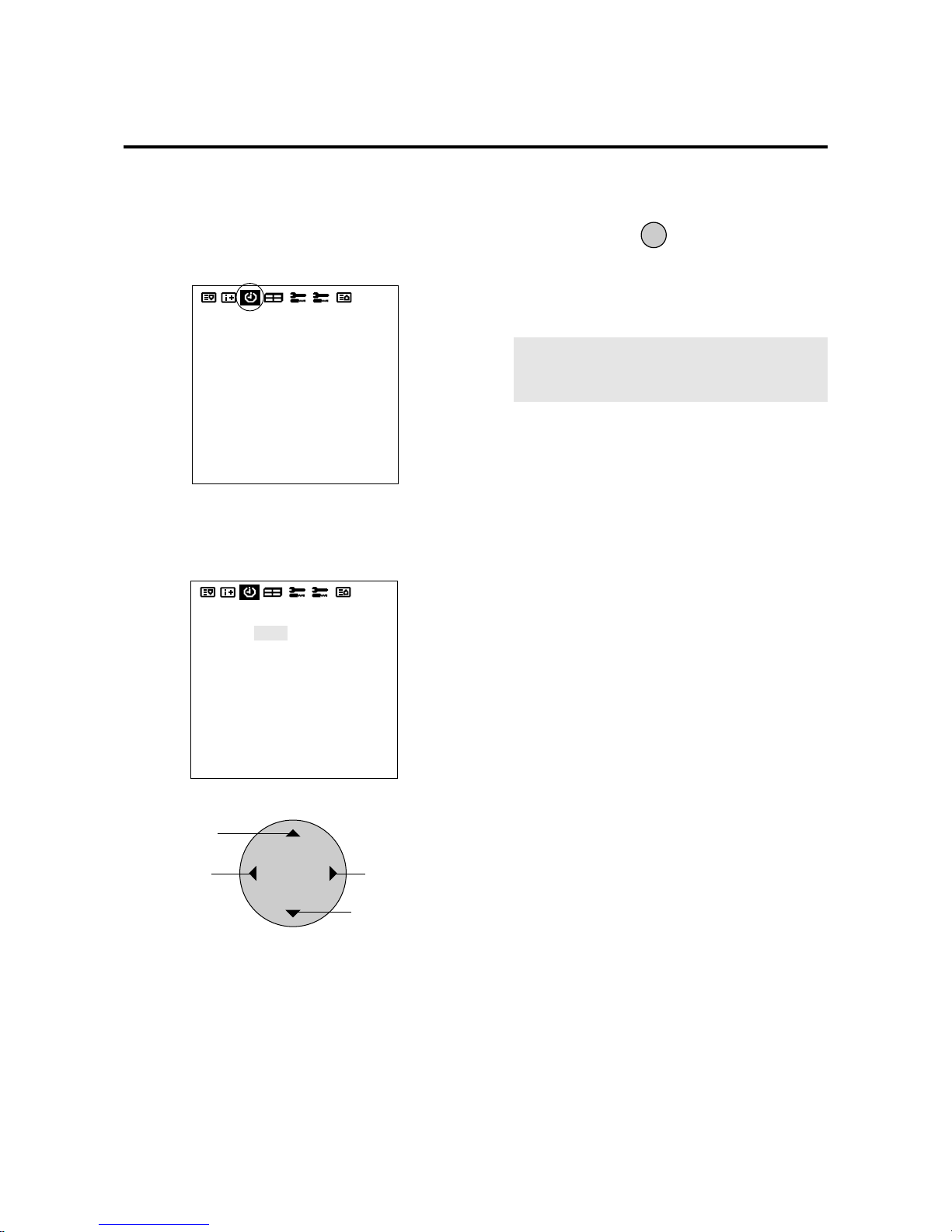
E-38
3. Align the cursor with SET and press PROCEED
* When the timer has been set, the LED will flash orange
every 3 seconds during remote control standby.
Timer Screen
This sets the date and time.
1. Align the cursor with icon (11) of the second page.
Icon (11)
The cursor is moved left and right with the POSITION
CONTROL§ / © buttons.
2. Use the ▲ / ▼ buttons to move to each of the year,
month, day, hour, and minute positions, and the § /
©
buttons to set the numbers.
POSITION / CONTROL
Numbers go
DOWN
Cursor moves in
the reverse direction
Number go UP
Cursor moves in
ordered direction
Setting range of date and time settings
Year: 1999 to 2099, Month: JAN to DEC, Day: 01 to 31
Hours: 00 to 24, Minutes: 00 to 59
PROCEED
PRESENT TIME
DATE : 1999. DEC 10
TIME : 22 : 30
SET
TIMER : OFF
PRESENT TIME
DATE : 1999. DEC 10
TIME : 22 : 30
SET
TIMER : OFF
Note:
Data can be maintained for about one
month by the built-in lithium battery even when the
AC cable is disconnected.
Page 38
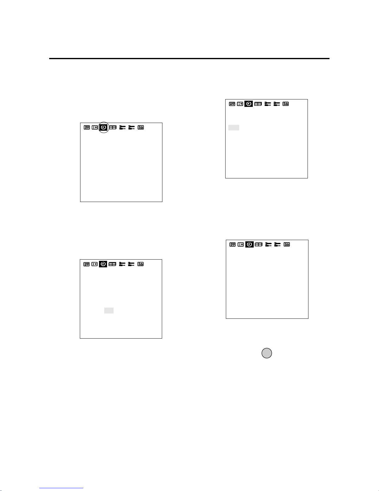
E-39
Auto Timer Screen
Used to turn the power ON/OFF, change inputs or enter
the invert mode.
1. Align the cursor with icon (11) of the second page of
the OSM.
The cursor is moved left and right with the POSITION
CONTROL§ / © buttons.
Icon (11)
2. Use the ▲ / ▼ buttons, select TIMER and switch ON
using the § / © buttons, then press the PROCEED
button.
* The cursor is moved up and down with the POSITION
CONTROL ▲ / ▼ buttons.
4. Use the ▲ / ▼ buttons to select a line item under
DATE.
The sub menu is displayed.
Auto Timer Screen
6. Use the ▲ / ▼ buttons to highlight DIRECT DAILY,
and WEEKL Y.
The DATE display is as follows:
EXIT
The cursor is moved up and down with the POSITION
CONTROL▲ / ▼ buttons.
PRESENT TIME
DATE : 1999. DEC 10
TIME : 22 : 30
SET
TIMER : OFF
PRESENT TIME
DATE : 1999. DEC 10
TIME : 22 : 30
SET
TIMER : ON
PRESS 'PROCEED' FOR
PROGRAM MENU
PROGRAM MENU
DATE
OCT30
JAN01
MON*
WED*
THU*
*
*
ON
10:10
22:15
15:45
09:00
08:15
13:30
21:00
OFF
13:00
24:00
19:00
11:00
10:00
14:30
22:00
MODE
VIDEO
INV
VIDEO
RGB1
RGB2
VIDEO
RGB1
1. DIRECT
2. DAILY
3. WEEKLY
3. Press PROCEED to enter the PROGRAM MENU.
5. Press PROCEED to select either DIRECT, DAILY,
and WEEKL Y.
7. Press EXIT to return to PROGRAM MENU.
DIRECT.....shows in the format of JAN-DEC**.
This relates to a given day that the function will be performed. The function will
only happen on that day at that time.
DAILY.......shows in the format of *.
This relates to a function being performed everyday for a predetermined
time.
WEEKLY .. shows in the format of MON, TUE,
WED, THU, FRI, SAT, SUN.
This relates to a function being performed on that specific day and time every week.
Page 39
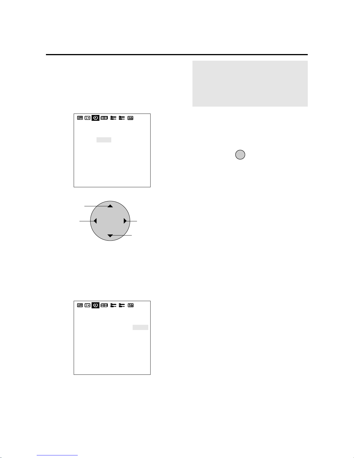
E-40
9. Use the ▲ / ▼ bottons to select MODE and set to
VIDEO, RGB1, RGB2, RGB3, INV or WT with the
§ / ©
buttons.
POSITION / CONTROL
DOWN
Cursor movement
UP
Cursor movement
* The left and right buttons change the following input
modes: VIDEO, RGB1 through RGB3, INV, WT.
10. Return to the main menu
* To delete the main menu, press the EXIT button once
more.
EXIT
* When the cursor is in the DATE position, a press of
the remote control CLEAR button will clear only that
program.
(The CLEAR button is valid only when the cursor is
in the DATE position.)
* The function can be used in up to 7 programs and the
program contents of a program will be deleted after
exiting the program.
* When the Timer function is set, the POWER/
STANDBY indicator is blinking orange at intervals
of 3 seconds.
8. Use the ▲ / ▼ bottons select the ON timer hour and
set with the § / © buttons.
Next, use the ▲ / ▼ bottons to select the ON time
minute and set with the § / © bottons.
Move onto the OFF time and perform the functions
as with the ON time.
Auto Timer Screen
PROGRAM MENU
DATE
OCT30
JAN01
MON*
WED*
THU*
*
*
ON
10:10
22:15
15:45
09:00
08:15
13:30
21:00
OFF
13:00
24:00
19:00
11:00
10:00
14:30
22:00
MODE
VIDEO
INV
VIDEO
RGB1
RGB2
VIDEO
RGB1
* The ON/OFF time is moved one digit at a time with
the up and down cursors, and the left and right buttons change the number UP and DOWN.
PROGRAM MENU
DATE
OCT30
JAN01
MON*
WED*
THU*
*
*
ON
10:10
22:15
15:45
09:00
08:15
13:30
21:00
OFF
13:00
24:00
19:00
11:00
10:00
14:30
22:00
MODE
VIDEO
INV
VIDEO
RGB1
RGB2
VIDEO
RGB1
Note:
•INV pro vides an in verse image of the incoming signal to reduce burn-in. The INV will work for the
last input selected.
Selecting “WT” displays the all white pattern to
reduce image burn-in.
Page 40
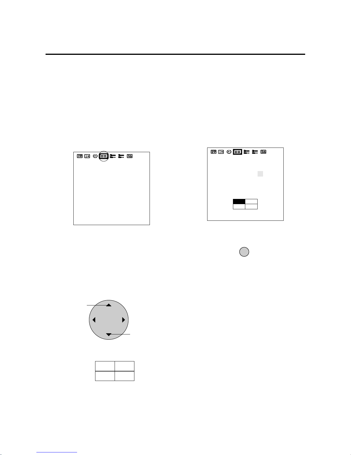
E-41
Multiple Screens
Select the screen mode from among 1, or 4 screens. (Normally 1 is selected.)
VIDEO WALL can be achieved from two or four screens
with the sole use of the main unit.
For information about compatible signals, see the Signal
Preset Table of factory setting values on Page E-47.
1. Align the cursor with icon (12) on the second page
Multiple Screens
The cursor is moved left and right with the POSITION
CONTROL§ / © buttons.
Icon (12)
2. Align the cursor using ▲ / ▼ buttons with the
SCREEN DIVIDER SETTING and use the § /
©
buttons to select 1 screen, or 4 screens.
Use the left and right cursors to change the setting
between 1 → 4 → in toggle fashion. (The initial value
is 1.)
POSITION / CONTROL
Move up
Move down
3. Align the cursor with POSITION OF SETTING and
set with the § / © buttons.
Nothing will be displayed when “1” is selected in the
SCREEN WALL MENU.
When “4” is selected, the icon of the right screen is
displayed.
Use the right cursor button to go clockwise and select
screen 1 from among the 4 screens. Set the number to
“1” at the upper left, and display “1 to 4” going
clockwise.
There is no selection for the initial value.
4. Return to the main menu
* To delete the main menu, press the EXIT button once
more.
EXIT
VIDEO WALL MENU
1. SCREEN DIVIDER
SETTING : 1
2. POSITION OF
DRIVER :
VIDEO WALL MENU
1. SCREEN DIVIDER
SETTING : 4
2. POSITION OF
DRIVER : NO.1
Screen selection:
4 Screens
No.1
No.4
No.2
No.3
Page 41

E-42
Other Setting Screens (1)
This allows the following settings: WIDE MODE, COLOR
SYSTEM, RGB MODE, POWER ON MODE, POWER
MANA GER, EXTERNAL CONTROL, HDTV SELECT ,
and ALL RESET.
1. Align the cursor with icon (13) of the second page.
The cursor is moved left and right with the POSITION
CONTROL§ / © buttons.
2. Align the cursor with the desired item
POSITION / CONTROL
Move up
Move down
3. Press the § / © buttons and set
* The § / © buttons are used to switch the various items
in toggle fashion as described below.
* COLOR SYSTEM:
AUTO/3.58 NTSC/PAL/SECAM/4.43 NTSC (Initial
value: A UTO)
4. Return to the main menu
* To delete the main menu, press the EXIT button once
more.
EXIT
* POWER ON MODE:
LAST MEM/VIDEO/RGB1/RGB2/RGB3 (Initial
value: LAST MEM (Last Memory))
* POWER MANAGER:
This means Power management of RGB input
ON/OFF (Initial value is OFF)
* EXTERNAL CONTROL:
OFF/1/2 (Initial value is OFF)
RS-232C can be used when “1” selected.
Open/Short control can be used when “2” is selected.
Other Setting Screens (1)
Icon (13)
COLOR SYSTEM
POWER ON MODE
POWER MANAGER
EXTERNAL CONTROL
ALL RESET
: AUTO
: OFF
: OFF
: LAST MEM
COLOR SYSTEM
POWER ON MODE
POWER MANAGER
EXTERNAL CONTROL
ALL RESET
: AUTO
: OFF
: OFF
: LAST MEM
Page 42
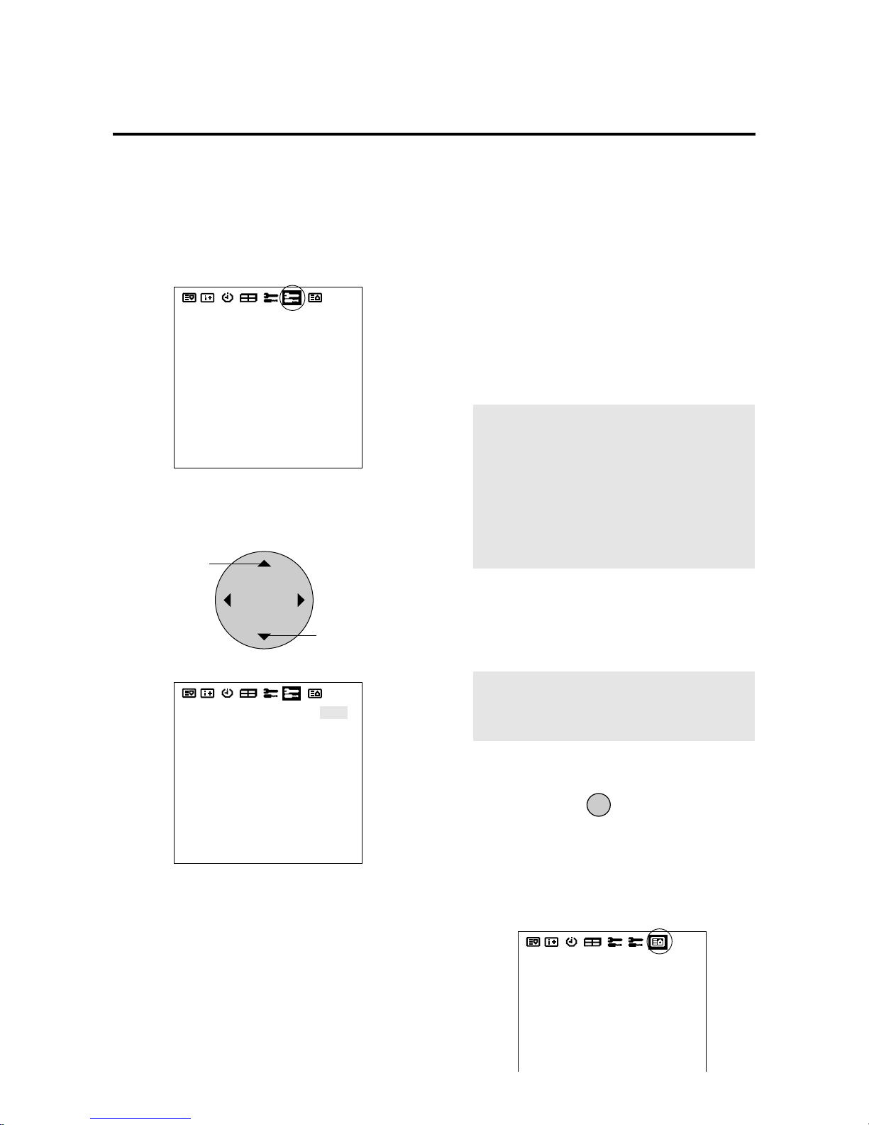
E-43
Other Setting Screens (2)
This allows the following settings: LONG LIFE MODE 1/
2/3 GRAY LEVEL, SET ID NO, and ALL RESET.
1. Align the cursor with icon (14) of the second page.
Icon (14)
The cursor is moved left and right with the POSITION
CONTROL§ / © buttons.
2. Align the cursor with the desired item
POSITION / CONTROL
Move up
Move down
Note:
Selecting ALL RESET and pressing the
PROCEED button will display a war ning screen and
pressing “PROCEED” further will change all the
settings of this screen to the initial values.
3. Press the ▲ / ▼ buttons and set
Select the various items with the left and right buttons
Burning reduction function
* LONG LIFE MODE 1: Switched ON/OFF with the
left and right buttons. (Initial value is OFF) → Holds
down the brightness of the screen.
* LONG LIFE MODE 2: Switched ON/OFF with the
left and right buttons. (Initial value is OFF) → Mo ves
the screen up, down, left, and right at fixed times.
* LONG LIFE MODE 3: Switched INV/WT/OFF with
the left and right buttons. (Initial value is OFF) →
Selecting “INV”displays the inverse image of the in
coming signal to reduce burn-in.
* Selecting “WT” displays the all white pattern to re-
duce image burn-in.
* GRAY LEVEL: Select 1 to 3 with the left and right
buttons. (Initial value is 1) → Adjusts the brightness
of the non-displayed portion of the screen.
* SET ID No.: Select 1 to 256 with the left and right
buttons. (Initial value is ALL) → Displays ALL with
the remote control or CLEAR button.
4. Return to the main menu
* To delete the main menu, press the EXIT button once
more.
EXIT
LONG LIFE MODE 1
LONG LIFE MODE 2
LONG LIFE MODE 3
GRAY LEVEL
SET ID NO
RGB3 ADJ
ALL RESET
: OFF
: OFF
: OFF
: 1
: ALL
: 1
LONG LIFE MODE 1
LONG LIFE MODE 2
LONG LIFE MODE 3
GRAY LEVEL
SET ID NO
RGB3 ADJ
ALL RESET
: OFF
: OFF
: OFF
: 1
: ALL
: 1
Previous Page Screen
Icon (15)
* Align the cursor with icon (15) at the very top to move
to the first page menu screen.
SOURCE INFO.
RGB1
H-FREQ.
V-FREQ.
H-POL.
V-POL.
31.5kHz
60.0Hz
NEG
POS
Notice - About RGB3 ADJ
If the image is not stable when in the RGB3 input mode,
switch the “RGB3 ADJ” number to 2 or 3. (Select the
mode at which the display is stable.)
The display position will change when the number is
changed; therefore, when using the unit with “AUTO PICTURE” ON, switch it OFF and then back ON again to return the display position to its original location.
When using the unit with “AUTO PICTURE” OFF,
please perform the display position adjustment again.
Note:
The long life mode is designed to extend the
service life of the plasma panel and reduce ghost images. It is not meant to prevent ghost images.
LONG LIFE MODE 2 cannot be set with multiple
screens operation.
Switching to GAMMA is not possible when LONG
LIFE MODE3 is set
LONG LIFE MODE 3: When the plasma monitor
is turned on or off, the INV. WT setting is set to
OFF and the last data is not stored in memory.
Page 43
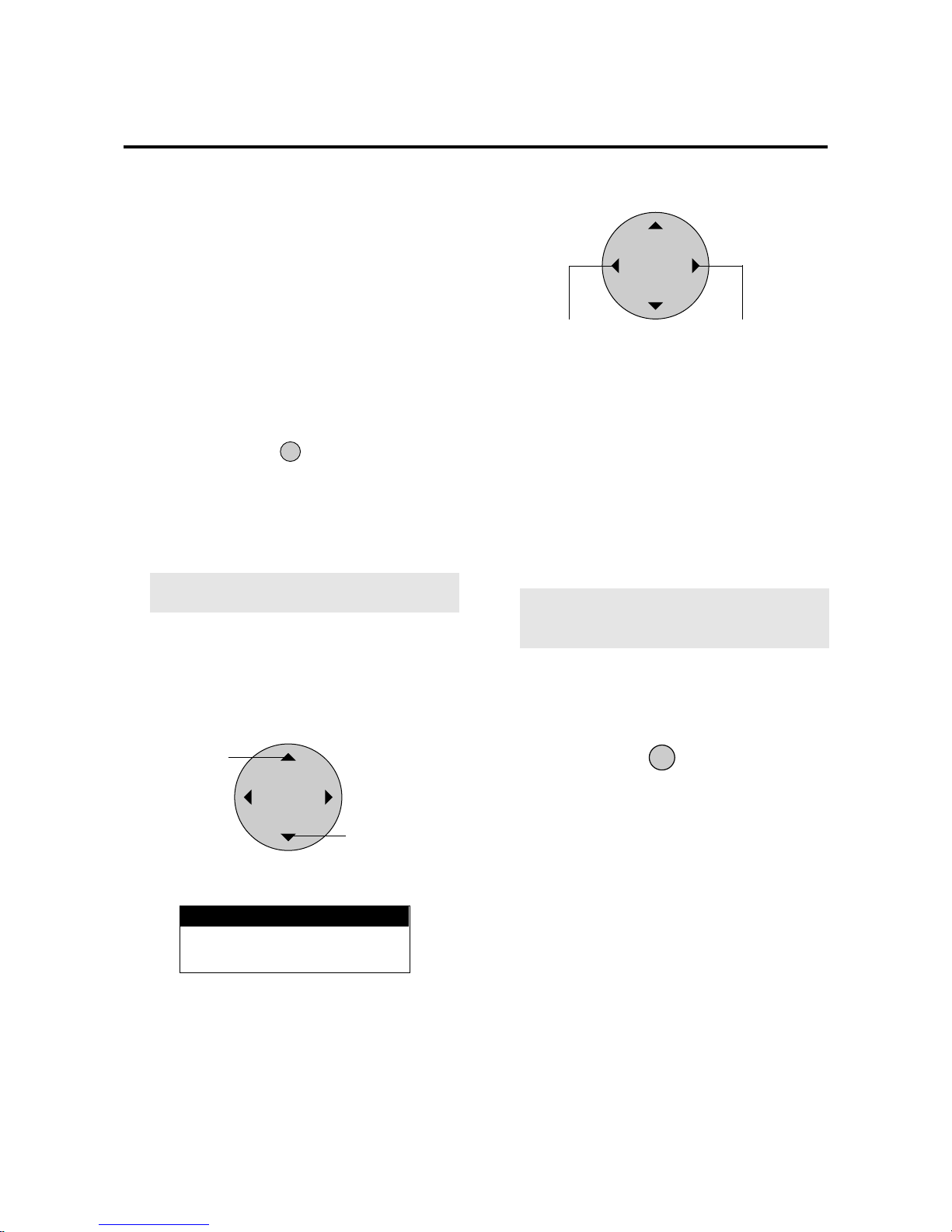
E-44
Set Selection Screen for Allotting ID Numbers to
Multiple Screens/Each Set
This sets the VIDEO WALL NO. and SET ID NO.
ID Selection Screen
2. Align the cursor with the desired item
ID SELECT
POSITION / CONTROL
Move up
Move down
ID Selection Screen
4. Return to the main menu
The display will go off when the EXIT button is pressed
or when the DISPLAY TIME setting time has elapsed.
3. Set to the desired value
POSITION / CONTROL
VIDEO WALL No.
* The POSITION CONTROL§ / © buttons are used to
switch the numbers from 1 through 4.
* A press of the remote control CLEAR button causes
a reset. (Initial value is ALL)
SET ID No.
* The POSITION CONTROL§ / © buttons are used to
enter numbers from 1 through 256. Note that entry of
numbers higher than 256 is not possible.
* A press of the remote control CLEAR button causes
a reset. (Initial value is ALL)
Note:
When both ID numbers have been set, the
priority order will be as described below.
VIDEO WALL > SET ID
EXIT
ID SELECT MENU
VIDEO WALL NO
SET NO
: 1
: 256
Numbers go DOWN
Numbers go UP
1. Press the ID SELECT button of the remote control
This displays the ID selection screen.
Press the EXIT button twice.
Press the EXIT button once to return to the main menu.
To delete the main menu, press the button once more.
* Selects the ID number for each monitor in a Multiple
screen so that each monitor can be adjusted with the
remote control one at a time.
* Only monitors that have been set with the appropriate
ID number can be controlled.
Note:
The ID select button is valid regardless of
the ID set for each monitor.
* This function is also valid when this monitor is con-
trolled via the RS232 connector.
Page 44
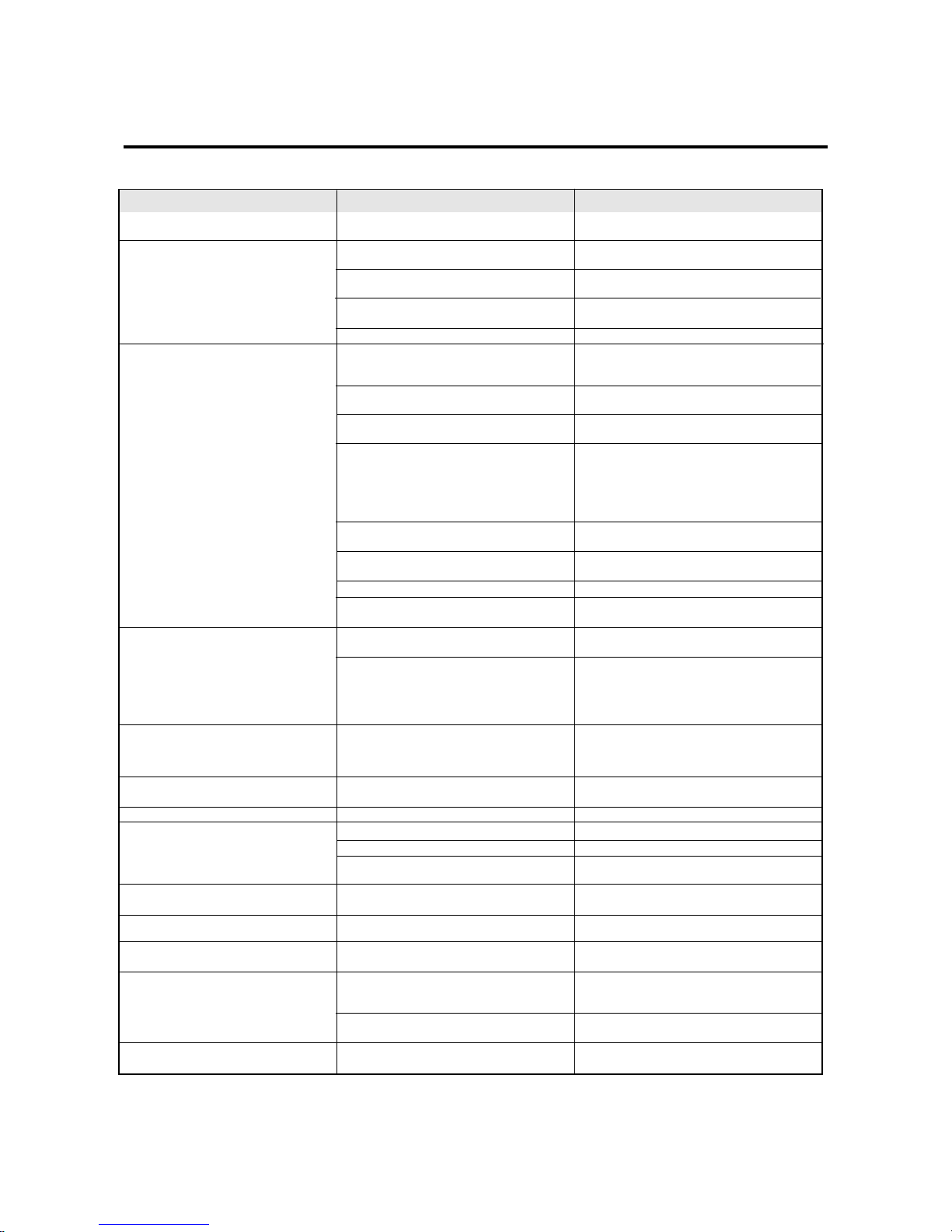
E-45
• Is a connected component set directly in front
or at the side of the display?
• Is the monitor’s power cor d plugged into a
power outlet?
• Are all the monitor’s indicators off?
• Has an ID number been set for the main unit?
• Are the remote controller’s batteries worn out?
• Is the remote controller pointed at the monitor,
or is there an obstacle between the remote controller and the monitor?
• Is direct sunlight or strong artificial light shining on the monitor’s remote control sensor?
• You are not within the effective operating
range.(Wireless)
• Incorrect setting of DIP SW (Wireless)
When in the EXT.CONTROL mode, the
remote control unit will not operate the
monitor.
The remote cable is piugged into the
REMOTE IN terminal (Wireless).
• Is the EXTERNAL CONTROL setting 1 or
2?
• Has an ID number been set for the main unit?
• Are the remote controller's batteries worn out?
• The front panel buttons of the main unit do
not function
• Is the monitor's power cord plugged into a
power outlet?
• Power outlet inactive.
Power of external equipment is not ON.
External equipment has been incorrecty
connected.
Incorrect input selection.
• Improper control setting.
Local interference.
Cable interconnections.
Input impedance is not correct level.
• Improper control setting.
Incorrect 15 PIN connector pin connections.
• Are the tint and colors properly adjusted?
• Is the computer's power turned on?
• Is a source connected?
• Is the power manager function in the standby
or off mode?
• Is the position adjustment appropriate?
• Is the screen size adjustment appropriate?
• Is the computer's resolution setting
appropriate?
• Horizontal and/or vertical sync signal is not
present when the Intelligent Power Manager
control is on.
• POWER/STANDBY indicatoris flashing red
• The temperature inside the main unit has become too high and has activated the protector.
Troubleshooting
If the picture quality is poor or there is some other problem, check the adjustments, operations, etc., before requesting service.
• Leave some space between the display and the
connected components.
• Plug the monitor’s power cord into a po wer outlet.
• Plug the monitor’s power cord into a po wer outlet.
• Set an ID number with the ID SELECT button,
or set the ID number to ALL.
• Replace both batteries with new ones.
• Point the remote controller at the monitor’s remote control sensor when pressing buttons, or
remove the obstacle.
• Eliminate the light by closing curtains, pointing
the light in a different direction, etc.
• Use the remote control unit within 30º left and
right of centrer (at a diatance of 22ft).
• Set Pin No.2 to ON.
Unplung the remote cable from the monitor.
• Use the remote control to set the EXTERNAL
CONTROL to OFF.
• Set an ID number with the ID SELECT button,
or set the ID number to ALL.
• Replace both batteries with new ones.
• The front panel buttons do not function during
Control Lock
• Plug the monitor's power cord into a power outlet.
• Be sure wall switch is on and outlet has power.
Switch to ON or connect to an active AC outlet.
Correct all connections.
Press correct RGB1, RGB2, RGB3, or VIDEO
button.
• Adjust picture controls as needed.
Try another location for the monitor.
Be sure all connections are secure.
• Adjust picture controls as needed.
Check pin assignments and connections.
• Adjust the tint and color.
• Turn on the computer's power.
• Connect source to the monitor.
• Operate the computer (move the mouse. etc.)
• Adjust the “RGB ADJ.” properly.
• Make the adjustment with the wide screen setting.
• Set to the proper resolution.
• Check the input signal.
• The unit is OFF in the timer operation; this is
not a malfunction.
• Promptly switch off the power of the main unit
and wait until the internal temperature drops.
Symptom Checks
Remedy
In the following case, power off the monitor immediately and contact your dealer or authorized NEC Service Center.
The monitor turns off in 5 seconds after powering on and then the POWER/STANDBY indicater blinks. It indicaters that the power supply circuit or, one
more fans have been damaged.
Overheart protector
If the monitor becomes too hot, the overheat protector will be activated and the monitor will be turned off. If this happens., turn off the power to the
monitor and unplug the power cord. If the room where the monitor is installed is particularly hot, move monitor to a cooler location, and wait for the
monitor to cool for 60 minutes. If the problem persists, contact your NEC dealer for service.
Picture is disturbed.
Remote control unit operates erroneously .
Monitor’s power does not turn on when
the remote controller’s power button is
pressed.
Monitor does not operate when the remote controller’s buttons are pressed.
No Picture is produced.
Poor picture with VIDEO signal input.
Poor picture with RGB signal input.
Tint is poor or colors are weak.
Nothing appears on screen.
Part of picture is cut off or picture is not
centered.
Image is too large or too small.
Picture is unstable.
POWER/STANDBY indicator is lighted
in orange or yellow.
POWER/STANDBY indicator is blinking
in green.
Page 45
E-46
Specifications
Plasma Screen 42 inch Visual size (Diagonal), AC Drive type
Aspect ratio : 16:9
Optical filter coating
Display color : 16,770,000 colors 256 levels
RGB Input Terminals RGB 1 : mini D-SUB 15pin
RGB 2 : BNC (R,G,B, H/CS and V)
RGB 3 : Digital RGB (DVI 24+5pin: Not compatible with analog input.
Complies with DVI
Video : Analog 0.7Vp-p/75 Ohms (Positive)
: Sync. : Separate Sync. TTL level, 0.7 - 4.0Vp-p/75 Ohms..........BNC only
Horizontal Sync. (Positive/Negative)
Vertical Sync. (Positive/Negative)
: Composite Sync. TTL Level (Positive/Negative)
: Composite Sync. On Green Video 0.3Vp-p (Negative)
RGB Output Terminals BNC (R,G,B, H/CS and V)
THROUGH OUT RGB THROUGHOUT (RGB2 only)
Video Input Terminals 1.0Vp-p, 75 Ohms unbalanced (BNC-Jack), Composite video signal, Sync-negative.
VIDEO Y : 1.0Vp-p, 75 Ohms unbalanced, Sync-negative.
S-VIDEO C : 0.28Vp-p, 75 Ohms unbalanced, Color burst level.
Video Output Terminals
THROUGH OUT 1.0Vp-p, 75 Ohms unbalanced (BNC Jack), Composite video signal, Sync-negative.
THROUGH OUT (S-VIDEO) Y : 1.0Vp-p, 75 Ohms unbalanced, Sync-negative.
C : 0.28Vp-p, 75 Ohms unbalanced, Color burst level.
External Control mini D-SUB 15pin (IN/THROUGH OUT)
(IN/THROUGH OUT) Open/Short, RS-232C Control
Synchronization Range Horizontal : 15.5 to 68.7 KHz (automatic : step scan)
Vertical : 46.0 to 85.0 Hz (automatic : step scan)
Maximum Resolution RGB : 853( H) x 480(V) pixels
Power Supply 100-240 VAC, 50/60 Hz
Current Rating 5.6A (maximum,)
Power consumption 430W (typical)
Dimensions 39.3(W) x 23.4(H) x 4.5(D) inches / 998(W) X 595(H) X114(D) mm
Weight 72.7lbs/33kg
Environmental Considerations Operating Temperature : 0 to 40
Humidity : 20 to 80%
Altitude : 0 to 6233 feet(1900m)
Storage Temperature : -10 to 50
Humidity : 10 to 90%
Altitude : 0 to 9842 feet(3000m)
Regulations : Meets EMC Directive (EN55022, EN61000-3-2, EN61000-3-3, EN55024)
Meets AS/NZS 3548 Class A.
Meets Low Voltage Directive (EN60950, SEMKO Approved)
All specifications are subject to change without notice.
PlasmaSync 42PD2 (Model PX-42VP2G)
Page 46
E-47
PlasmaSync 50PD1 (Model PX-50VP1G)
Plasma Screen 50 inch Visual size (Diagonal), AC Drive type
Aspect ratio : 16:9
Optical filter coating
Display color : 16,770,000 colors 256 levels
RGB Input Terminals RGB 1 : mini D-SUB 15pin
RGB 2 : BNC (R,G,B, H/CS and V)
RGB 3 : Digital RGB (DVI 24+5pin: Not compatible with analog input.
Complies with DVI
Video : Analog 0.7Vp-p/75 Ohms (Positive)
: Sync. : Separate Sync. TTL level, 0.7 - 4.0Vp-p/75 Ohms..........BNC only
Horizontal Sync. (Positive/Negative)
Vertical Sync. (Positive/Negative)
: Composite Sync. TTL Level (Positive/Negative)
: Composite Sync. On Green Video 0.3Vp-p (Negative)
RGB Output Terminals BNC (R,G,B, H/CS and V)
THROUGH OUT RGB THROUGHOUT (RGB2 only)
Video Input Terminals 1.0Vp-p, 75 Ohms unbalanced (BNC-Jack), Composite video signal, Sync-negative.
VIDEO Y : 1.0Vp-p, 75 Ohms unbalanced, Sync-negative.
S-VIDEO C : 0.28Vp-p, 75 Ohms unbalanced, Color burst level.
Video Output Terminals
THROUGH OUT 1.0Vp-p, 75 Ohms unbalanced (BNC Jack), Composite video signal, Sync-negative.
THROUGH OUT (S-VIDEO) Y : 1.0Vp-p, 75 Ohms unbalanced, Sync-negative.
C : 0.28Vp-p, 75 Ohms unbalanced, Color burst level.
External Control mini D-SUB 15pin (IN/THROUGH OUT)
(IN/THROUGH OUT) Open/Short, RS-232C Control
Synchronization Range Horizontal : 15.5 to 68.7 KHz (automatic : step scan)
Vertical : 46.0 to 85.0 Hz (automatic : step scan)
Maximum Resolution RGB : 853( H) x 480(V) pixels
Power Supply 100-240 VAC, 50/60 Hz
Current Rating 7.4A (maximum)
Power consumption 520W (typical)
Dimensions 47.8(W) x 28.6(H) x 5.1(D) inches / 1214(W) X 727(H) X129(D) mm
Weight 101.4lbs/46kg
Environmental Considerations Operating Temperature : 0 to 40
Humidity : 20 to 80%
Altitude : 0 to 6233 feet(1900m)
Storage Temperature : -10 to 50
Humidity : 10 to 90%
Altitude : 0 to 9842 feet(3000m)
Regulations : Meets EMC Directive (EN55022, EN61000-3-2, EN61000-3-3, EN55024)
Meets AS/NZS 3548 Class A.
Meets Low Voltage Directive (EN60950, SEMKO Approved)
All specifications are subject to change without notice.
Page 47
E-48
Appendix
Signal Identification For Raster Preset
VIDEO NTSC*1
VIDEO PAL*1 VIDEO SECAM*1
640 X 240 (15.734kHz/59.94Hz)
768 X 288 (15.557kHz/50.39Hz)
640 X 400 (31.469kHz/70.086Hz)
640 X 480 (31.469kHz/59.94Hz)
640 X 480 (35kHz/66.667Hz)
640 X 480 (37.861kHz/72.809Hz)
640 X 480 (37.5kHz/75Hz)
640 X 480 (43.269kHz/85.008Hz)
640 X 480 (39.375kHz/75Hz)
800 X 600 (35.156kHz/56.25Hz)
800 X 600 (37.879kHz/60.31Hz)
800 X 600 (48.077kHz/72.188Hz)
800 X 600 (46.875kHz/75Hz)
800 X 600 (53.674kHz/85.061Hz)
832 X 624 (49.725kHz/74.55Hz)
852 X 480 (31.722kHz/59.966Hz)
848 X 480 (31.02kHz/60Hz)
1024 X 768 (56.476kHz/70.069Hz)
1024 X 768 (60.023kHz/75.029Hz)
1024 X 768 (68.677kHz/84.997Hz)
1024 X 768 (60.24kHz/74.93Hz)
768 X 576 (31.389kHz/50Hz)
640 X 480 (31.47kHz/59.9Hz)
VU-6010 NTSC*2
VU-6010 PAL*2
IBM 400@70Hz*3
VESA 480@60Hz
MAC @13''*6
VESA 480@72Hz
VESA 480@75Hz
VESA 480@85Hz*4
XGA-2 480@75Hz
VESA 600@56Hz
VESA 600@60Hz
VESA 600@72Hz
VESA 600@75Hz
VESA 600@85Hz*4
MAC @16''*6
I/O data wide*5
VGA WIDE (NEC1)
VESA 768@70Hz
VESA 768@75Hz
VESA 768@85Hz*4
MAC @19''*6
IDC-3000G PAL625P
IDC-3000G NTSC 525P
-
-
-
-
-
STILL
-
-
-
-
-
-
-
-
-
-
-
-
-
-
-
-
-
-
MOTION
C
C
C
C
C
C
C
C
C
C
C
C
C
C
C
C
C
C
C
C
C
C
C
C
C
C
C
C
C
C
C
C
C
C
C
C
C
C
C
C
C
C
C
C
C
C
C
C
C
C
Factory
settings
User
settings
RGB
MODE
-
-
4 x 3
-
-
4 x 3
-
-
-
-
-
-
-
-
-
-
-
16 x 9
-
-
-
-
-
-
4 x 3
INPUT
MODE*7
-
-
NEG
NEG
NEG
NEG
-
NEG
NEG
POS
NEG
POS
POS
POS
POS
POS
-
NEG
POS
NEG
POS
POS
-
NEG
NEG
-
-
NEG
NEG
NEG
NEG
-
NEG
NEG
POS
NEG
POS
POS
POS
POS
POS
-
NEG
POS
NEG
POS
POS
-
NEG
NEG
Y
Y
Y
Y
-
Y
Y
Y
Y
Y
Y
Y
Y
Y
-
Y
Y
Y
Y
Y
-
Y
Y
Y
Y
Y
Y
-
Y
Y
Y
Y
Y
Y
Y
Y
Y
-
Y
Y
Y
Y
Y
-
Y
Y
Sync polarity
Ver
Hor
Ver
Hor
*1 Convert to 640 dots x 480 lines and display.
*2 These signals cannot be displayed in the RGB3 input mode.
*3 Display only 400 lines with the screen center of the vertical orientation located at the center.
*4 The picture will be shaky when the moving images of video games, etc., are input. (In this case set the refresh rate to 75 kHz or less.)
*5 Only when using an I/O DATA graphic accelerator board.
*6 Use a separately sold signal adapter (mini D-Sub 15-pin) when connecting to a Macintosh computer.
For some models, make the mini D-Sub 15-pin connection using the included RGB signal cable.
These signals are Sync On Green.
*7 Make the settings to display these signals. The signals will not be displayed properly unless the correct settings are made.
*The resolution deteriorates in comparison with the original image because the image of 640 dots x 480 lines is converted to 853 dots x 480 lines and displayed.
*At the time of video input, video signals derived from poor recording conditions may give rise to a disturbed screen image.
*The sync may be disturbed when non standard signals other than the aforementioned are input.
*Multiple screens (2 screens) can only display signals having an aspect ratio of 4:3. *3 Cannot be used with multiple screens.
*With digital inputs some signals are not accepted.
*852 dot by 480 line signals are displayed with this resolution.
*848 dot by 480 line signals are displayed at a resolution of 848 dots by 480 lines when “NORMAL” is selected, and converted to 853 dots by 480 lines
when “FULL” is selected.
Resolution
(horizontal frequency/vertical frequency)
Presence/absence of sync
Page 48
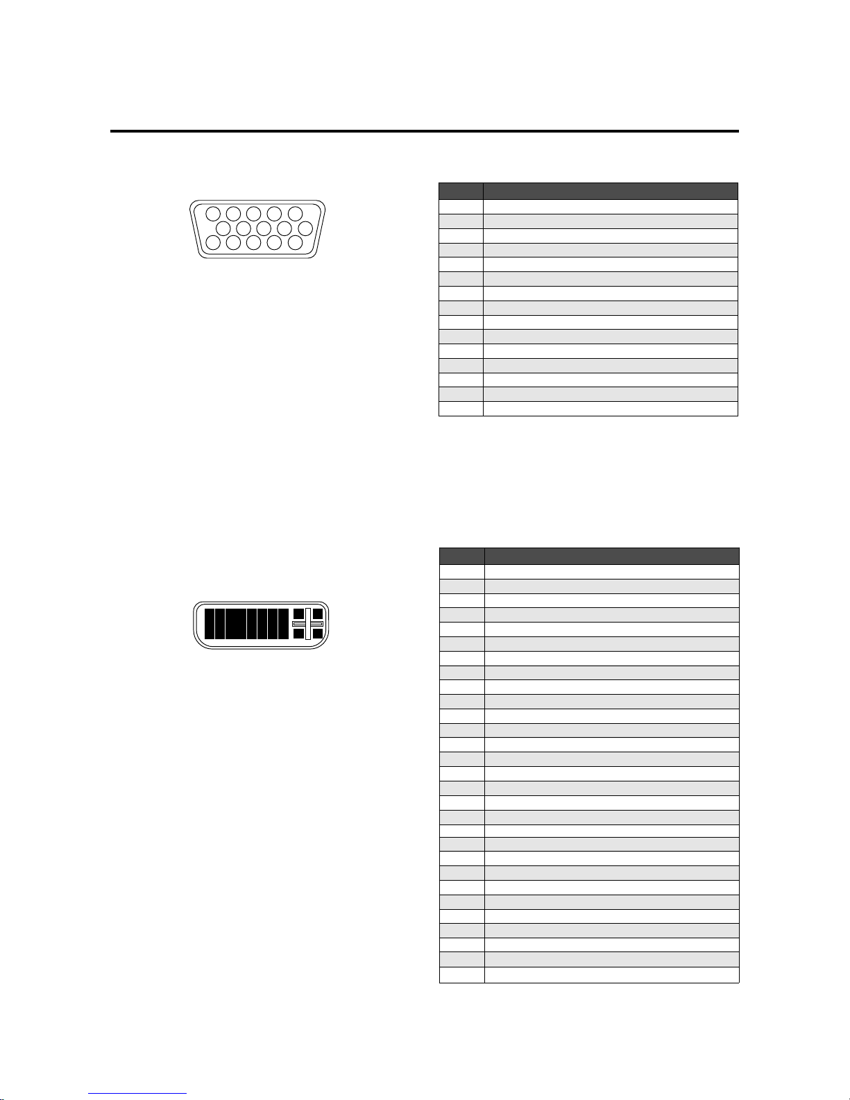
E-49
Pin No.
1
2
3
4
5
6
7
8
9
10
11
12
13
14
15
Signal (Analog)
Red
Green or sync-on-green
Blue
Ground
Ground
Red ground
Green ground
Blue ground
No connection
Sync signal ground
Ground
Bi-directional DATA (SDA)
Horizontal or composite sync
Vertical sync
Data clock
1
2
34
5
11
12
13
1415
6
7
8
9
10
Signal level
VIDEO signal : 0.7Vp-p (Analog)
Sync signal : TTL level
Pin Configuration and Signal Level of mini D-Sub 15-Pin (Analog) Input Connector
RGB 1
Pin Configuration and Signal of the RGB 3 IN Connector (DVI Connector)
Pin No.
1
2
3
4
5
6
7
8
9
10
11
12
13
14
15
16
17
18
19
20
21
22
23
24
25
26
27
28
29
Signal (Digital)
T.M.D.S Data 2 T.M.D.S Data 2 +
T.M.D.S Data 2 Shield
No connection
No connection
DDC Clock
DDC Data
No connection
T.M.D.S Data 1 T.M.D.S Data 1 +
T.M.D.S Data 1 Shield
No connection
No connection
+5V Power
Ground
Hot Plug Detect
T.M.D.S Data 0 T.M.D.S Data 0 +
T.M.D.S Data 0 Shield
No connection
No connection
T.M.D.S Clock Shield
T.M.D.S Clock +
T.M.D.S Clock No connection
No connection
No connection
No connection
No connection
1
9
17
2
10
18
3
11
19
4
12
20
5
13
21
6
14
22
7
15
23
8 25 26
27 28
16
24
29
RGB 3
The unit is equipped with a type of connector commonly
used for both analog and digital.
(Functionally, this cannot be used for analog input.)
(TMDS can be used for one link only)
Page 49
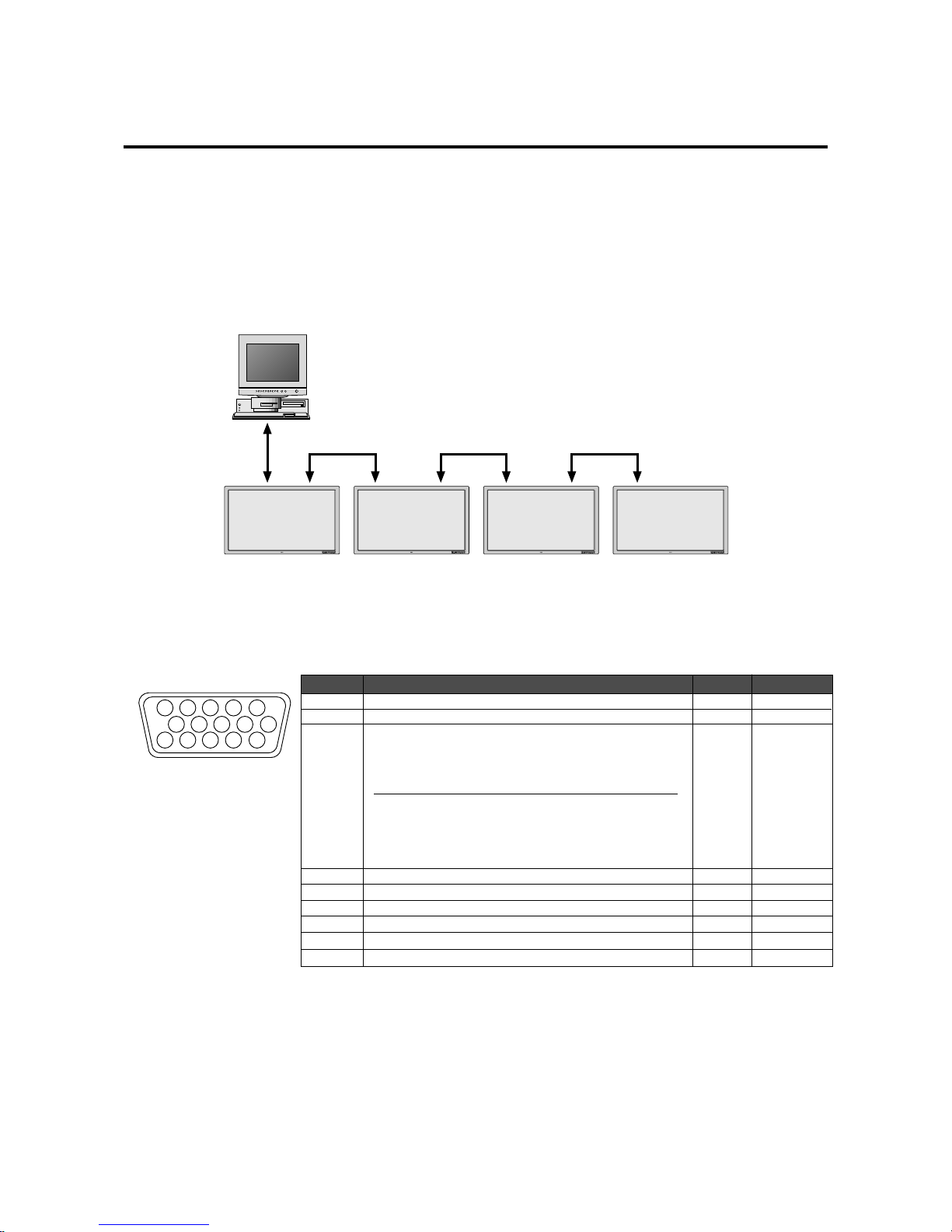
E-50
1
2
34
5
11
12
13
1415
6
7
8
9
10
EXTERNAL CONTROL
Pin No.
1 to 3
4
5 and 14
6 to 8
9 and 10
11
12
13
15
Function
Not used
Power ON/OFF
OpenONEstablished
OFF
Input switching
The input mode is switched by the combination of pin numbers 5 and 14.
Not used
Ground
TXD (RS-232C)
RTS
RXD (RS-232C)
CTS
Input Pin No. 5 Pin No. 14
VIDEO Open Open
RGB1 Ground Open
RGB2 Open Ground
RGB3 Ground Ground
Application
These specifications are applicable to NEC plasma monitors (including 42- and 50-inch types) and communications control from external equipment.
Connections
Connections should be made as described below.
1) Display-side connector: EXTERNAL CONTROL connector
*A maximum of 4 units can used with a cascade connection.
External equipment
e.g., Personal computer
2) External equipment side connector: Serial port (RS-232C) connector
See the specifications of the connected equipment for information about the type of connector and pin assignment.
Function and Pin Configuration of the External Control Connector
PDP1 Display PDP4 DisplayPDP3 DisplayPDP2 Display
Page 50
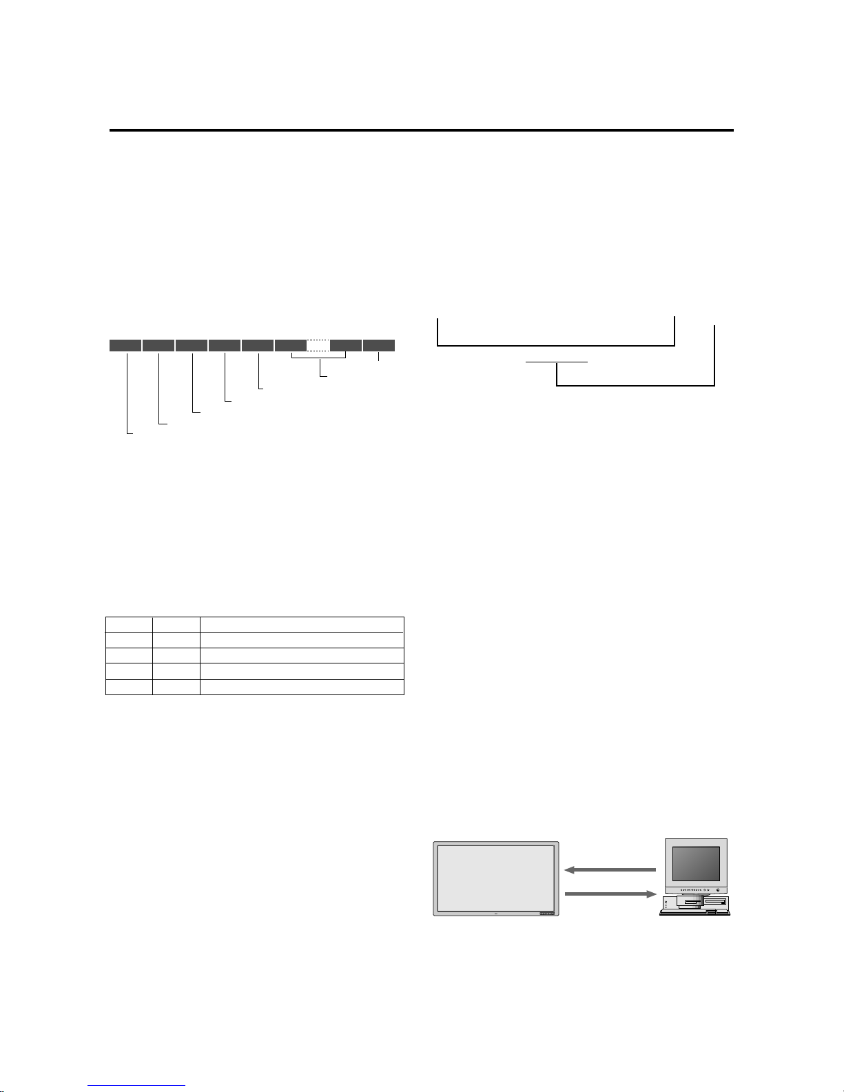
E-51
8bit 8bit 8bit 8bit 8bit 8bit 8bit 8bit
Command 1
UNIT ID 1
UNIT ID 2
Command 2
Data length
Data
Check Sum
Command 1
Together with Command 2, this is a number that distinguishes the various commands.
For ACK, when bit 2 and bit 3 are both “1”, reception of a
supported command or data is indicated. When bit 2 is
“0”, reception of an unsupported command or data is indicated.
Bit 0 and bit 1 should be set as described below.
Communication Parameters
(1) Communication system Asynchronous
(2) Interface RS-232C
(3) Baud rate 9600 bps
(4) Data length 8 bits
(5) Parity Odd
(6) Stop bit 1 bit
(7) Communication code Hex
Unit ID 1 and Unit ID 2
1) Unit ID1: Sets a number corresponding to the various
sets ID (1 through 4) when multiple screens are selected, and to 1 through 256 at the time of set ID selection. “00H” must be output when the ID is not set.
2) Unit ID2: Makes settings on the occasion of simultaneously operating all sets connected in cascade at the
time of multiple screen mode and at the time of set ID
selection.
Selection of all sets: FFH
At time of regular setting: 00H
bit0
0
0
1
1
bit1
0
1
0
1
Communication Format
When multiple screens are selected
Not used
At time of set ID selection
At time of regular use
Command 2
Together with Command 1, this is a number that distinguishes the various commands.
Check Sum (CKS), Error Processing, and ACK
1) Checks for receive data incorporate both the following
checksum and RS-232C (odd) parity.
The checksum comprises the following aspects of one
transmitted or received frame: Command 1, Unit 1 and
2, Command 2, data length, and the lower order 8 bits
of the total data.
2) Error Processing
(1) When the communications interval is 4 ms or
greater, the arrival of a subsequent Command 1
will be recognized. If meaningful data cannot be
discerned at this time, that data will not be recognized.
(2) When the receive data error, checksum error, and
the receive data could not all be taken in, ACK is
not returned.
3) Returning an ACK
When command processing exceeds 0.5 seconds following command reception, an ACK1 for which bit 3
of Command 1 has been set to “0” (during command
processing) is returned every 0.5 seconds until command processing is completed. When command processing is completed, an ACK2 for which bit 3 of
Command 1 has been set to “1” (at the end of command processing) is returned every 0.5 seconds until
command processing is completed. Bit 1 of Command
1 is set to 0 ; when the UA2 setting is FFH, it becomes
possible to simultaneously operate all sets connected
in cascade and as a result, ACK is not returned.
Communications Flow
When various commands are sent from a personal computer (PC) or other external equipment, the display is always ready to receive them.
Note that resending of the command is recommended
when an ACK is not returned from the display within 1.5
seconds.
Plasma display
Various commands
ACK
Check Sum Example
9FH 40H 4FH 01H 01H 30H
Command 1 Unit ID Command 2 Data Length Data Check Sum
Total 130H
▲
Personal computer
PC or other external equipment
Page 51
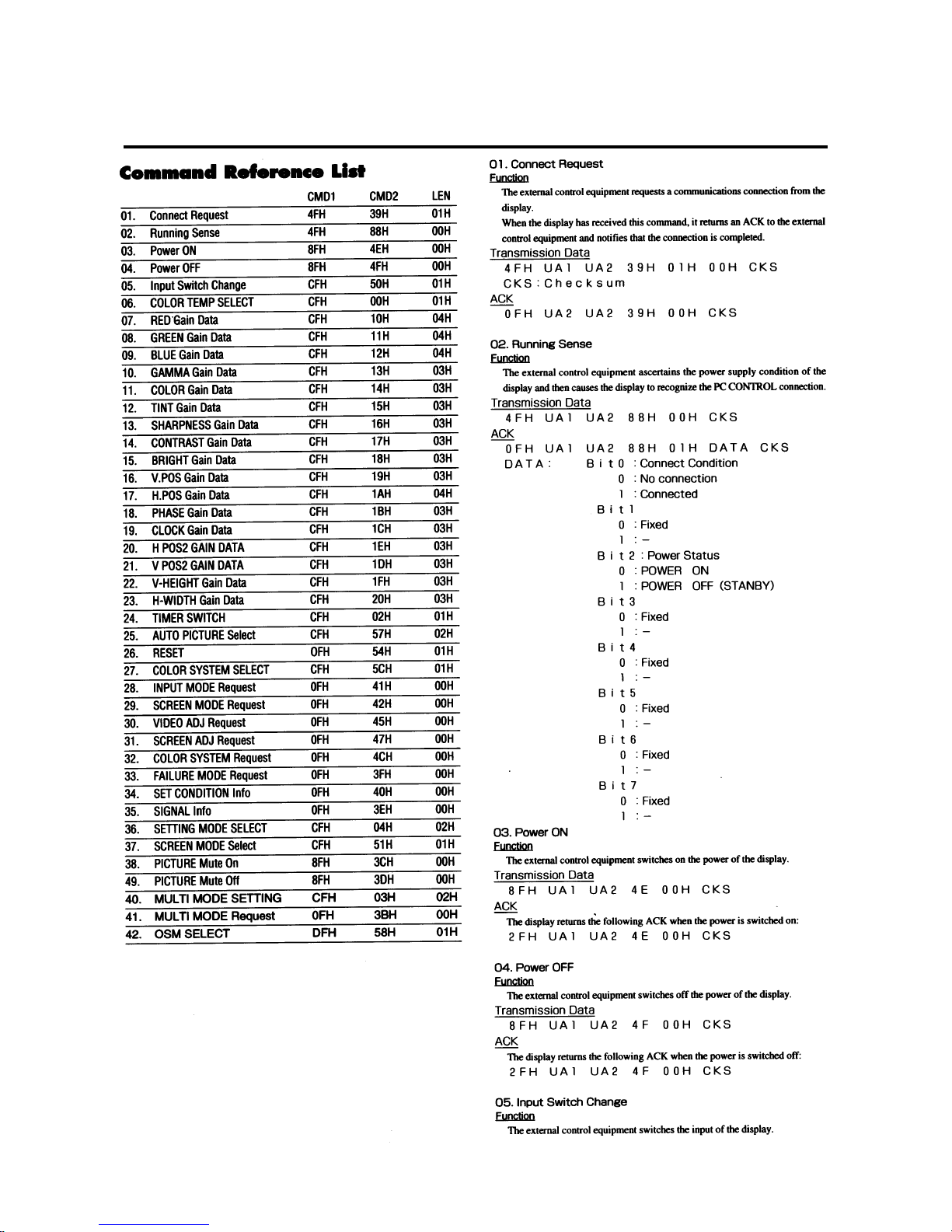
E-52
Page 52
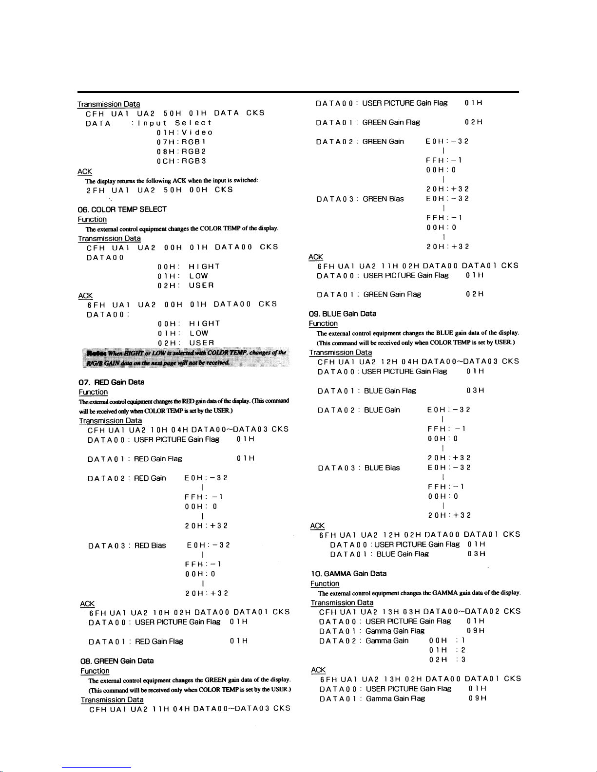
E-53
Page 53
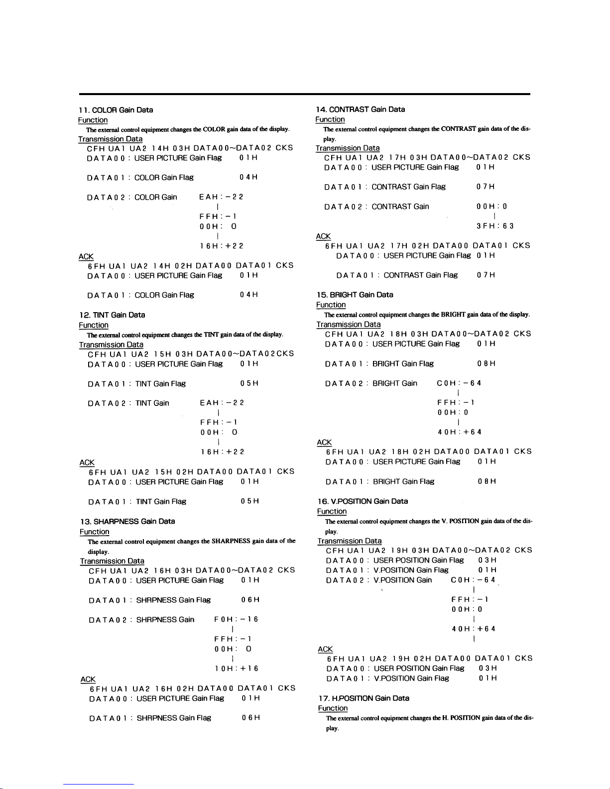
E-54
Page 54
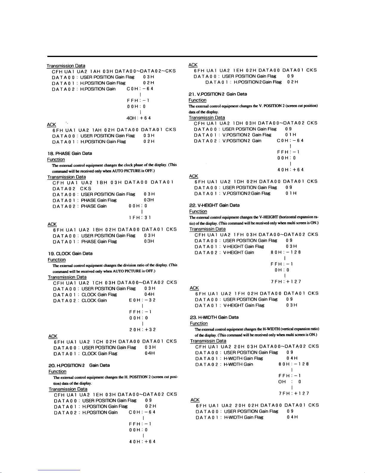
E-55
Page 55
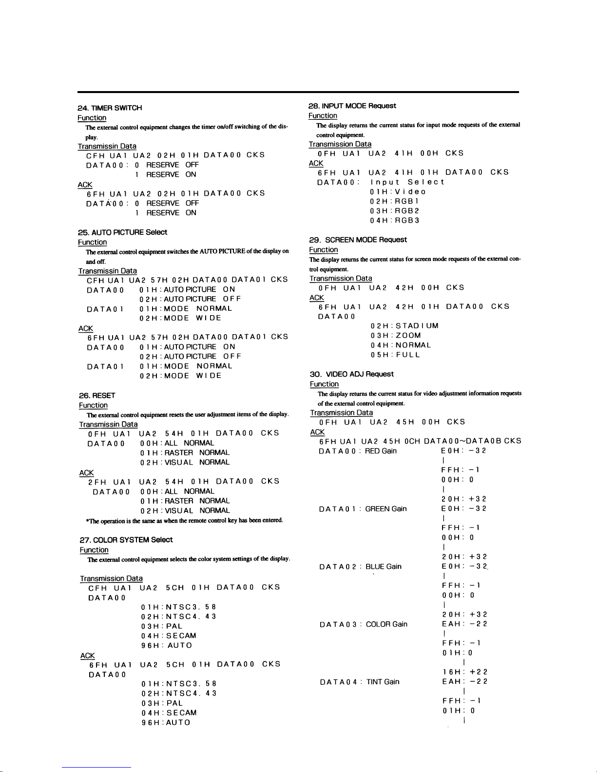
E-56
Page 56
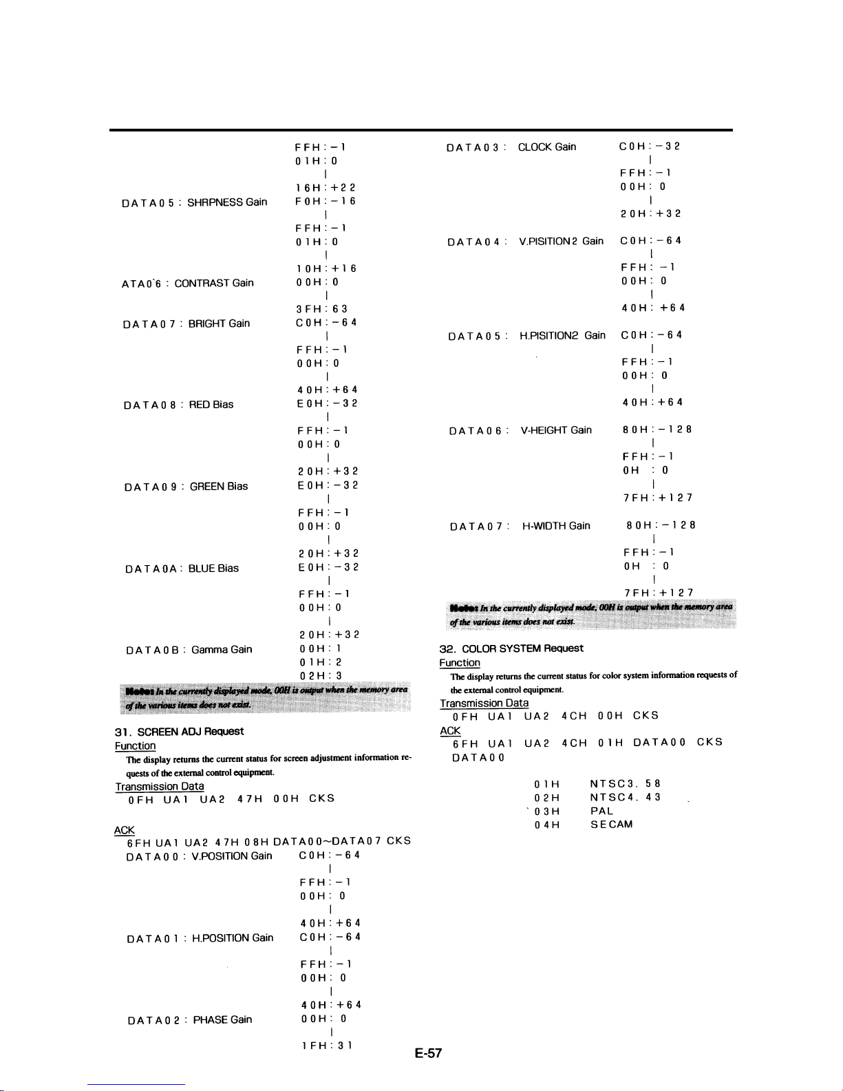
E-57
Page 57
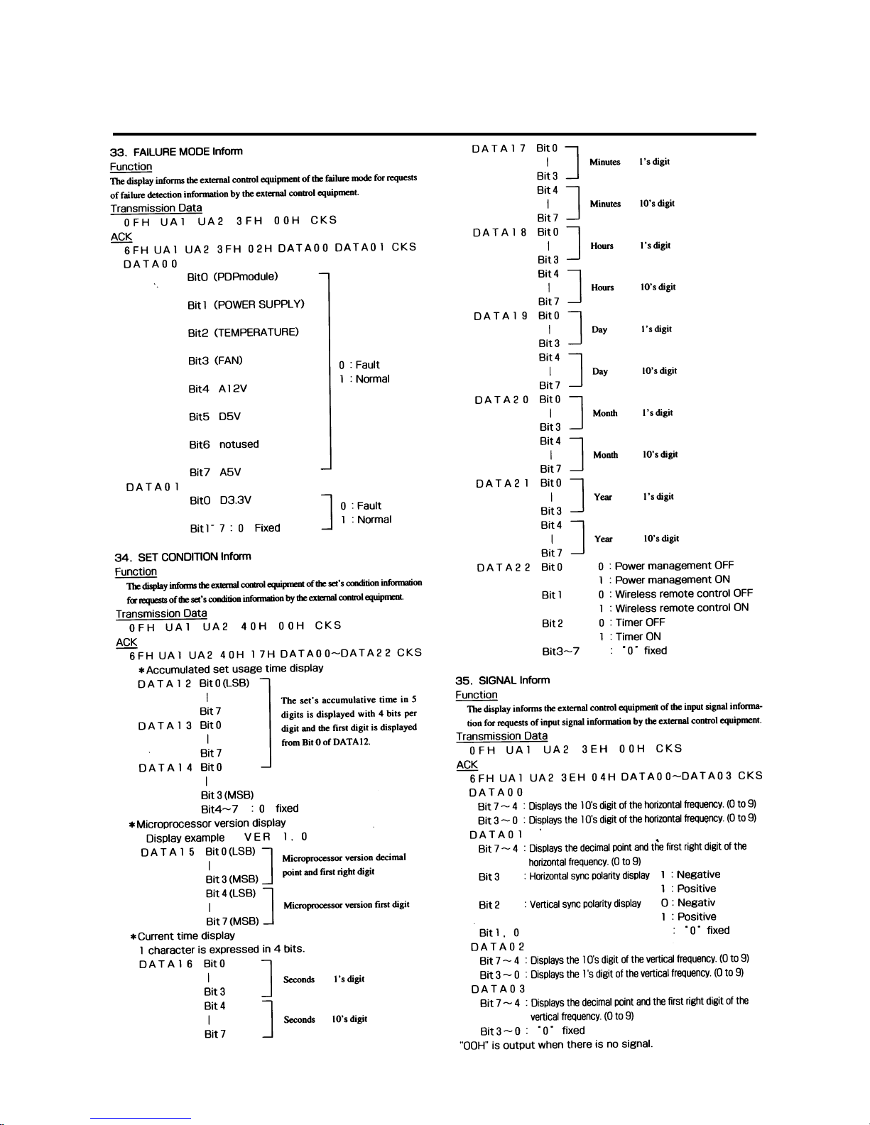
E-58
Page 58
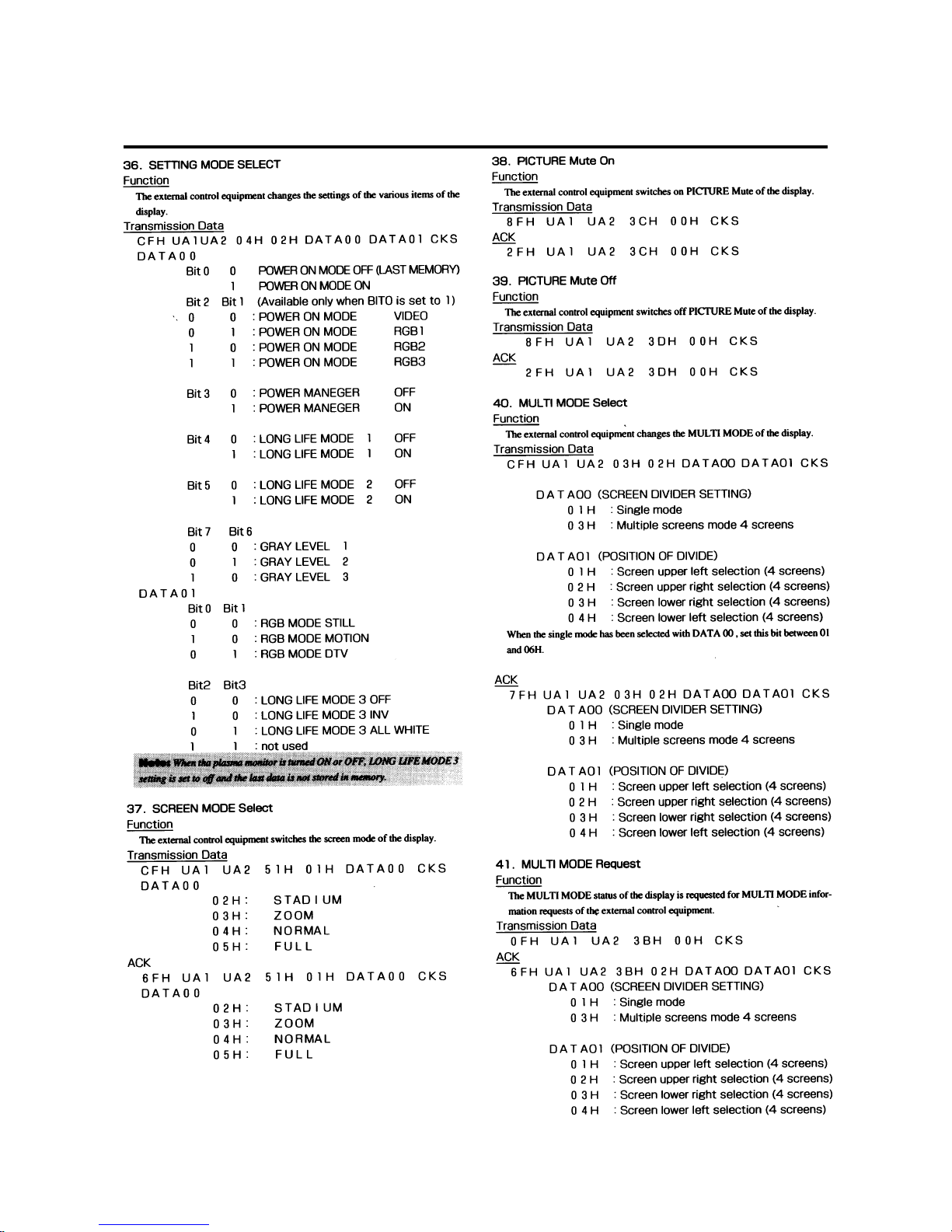
E-59
Page 59
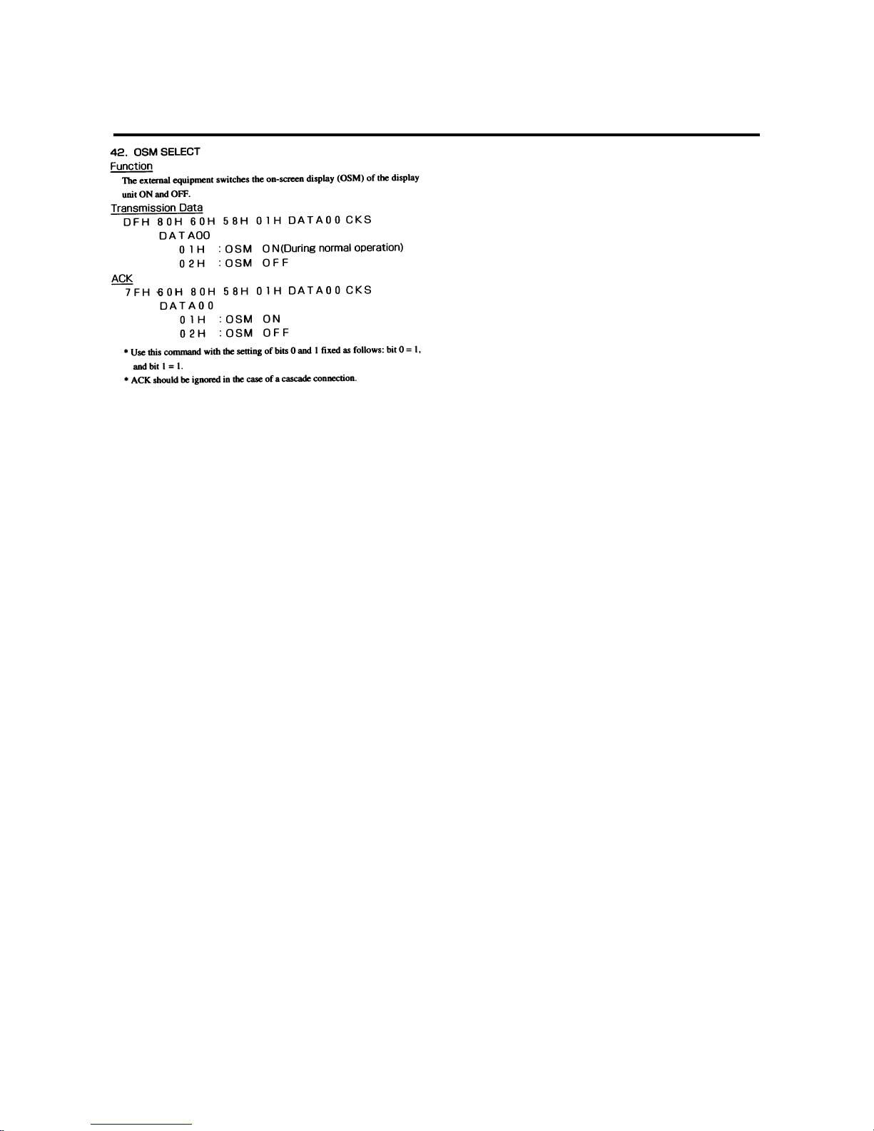
E-60
Page 60
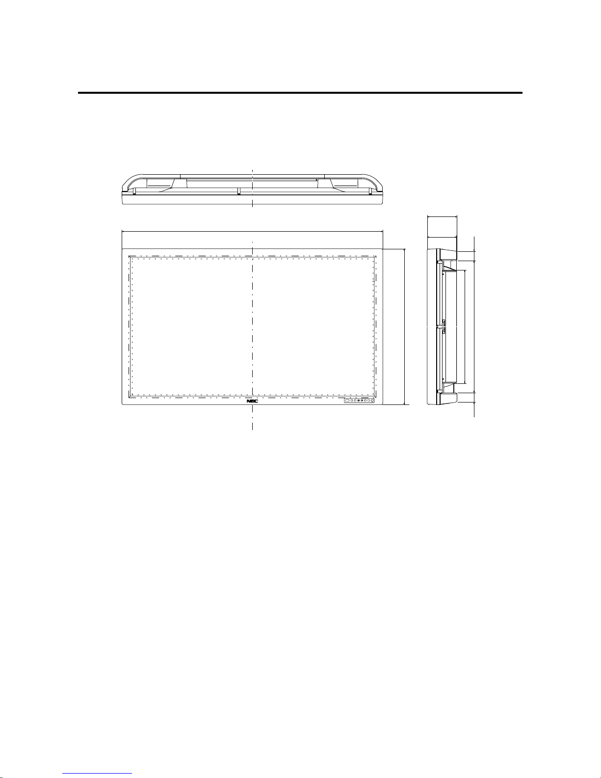
E-61
Unit : inch(mm)
Cabinet dimensions
PlasmaSync 42PD2 (Model PX-42VP2G)
39.3''(998)
23.4''(595)
17''(432)
1.4''(35.8)1.4''(35.8)
19.85''(504.08)
4.5''
(114)
4.4''
(112)
Page 61
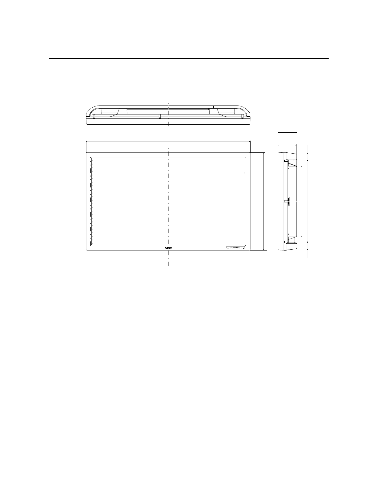
E-62
Unit : inch(mm)
Cabinet dimensions
PlasmaSync 50PD1 (Model PX-50VP1G)
47.8''(1214)
28.6''(727)
20.8''(528)
1.4''(35.8)1.4''(35.8)
25.06''(636.45)
5.1''
(129)
5.0''
(127)
 Loading...