

Page 1
Return to ProServa PH Page
1 Server Description
The NEC ProServa™ PH133 series of high performance Pentium® 133 MHz servers incorporate a modular
scaleable architecture that integrates a 64-bit bus interface with a Peripheral Component Interconnect (PCI)
PeerBus and an Extended Industry Standard Architecture (EISA) bus. The architecture supports symmetrical
multiprocessing (SMP) and a variety of operating systems. The bus interface is capable of handling multiple
processors with multiple cache resources in a quad-processor format.
The ProServa PH server's system board provides two central processing unit (CPU) module slots, two Error
Checking and Correcting (ECC) memory module slots, four PCI slots, and six EISA bus master slots. Four
standard peripheral bays can house optional diskette drives, tape back-up, CD-ROM (standard on some
configurations), and other mass storage devices. Six hot-docking bays provide over 12 gigabytes (GB) of storage.
The docking bays allow hot-swapping of SCSI hard disk drives without shutting down the server.
All server configurations contain a 525-watt power supply, 3 1/2-inch diskette drive, ECC memory module, and
CPU module. Several configurations contain two CPU modules, one or two 2-GB hard drives, an Intel
EtherExpress™ PRO/100B Adapter board, CD-ROM reader, Intel LANDesk Server Monitor, and a redundant
array of independent disks (RAID) controller. Figure 1-1 shows a typical server configuration. Table 1-1 lists the
server configurations.
Monitoring and control of the ProServa PH servers is provided by an onboard Interrupt Control ASIC (INCA)
component and several software applications, including Intel's LANDesk™ Server Control and LANDesk
Management Suite.
As application requirements increase, you can upgrade your system with dual or quad Pentium processors,
additional memory, additional drives and add-in expansion boards, and other peripheral devices.
Page 2

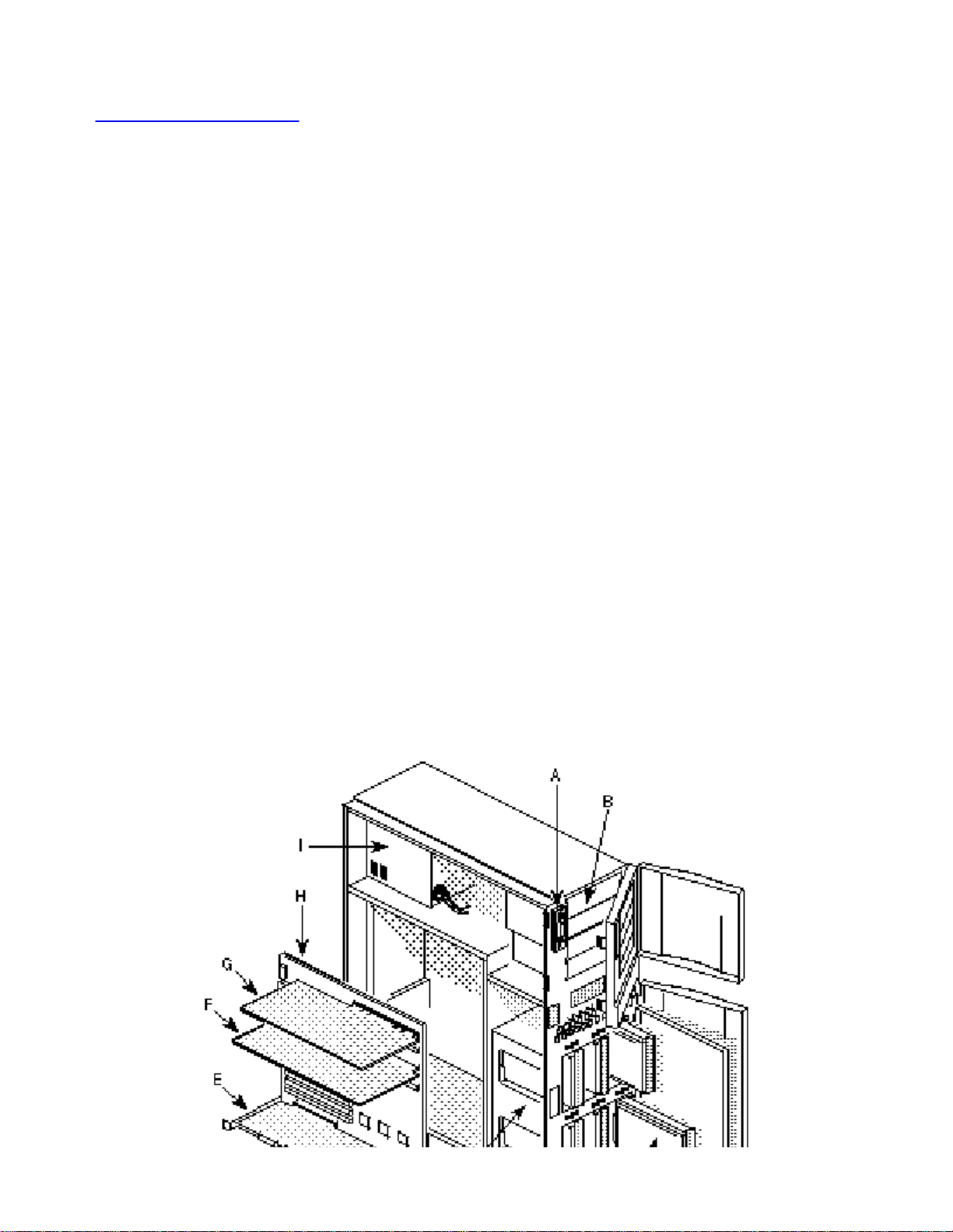
Figure 1-1. ProServa PH Server, Semi-exploded View
A ¾ 3 1/2-inch diskette drive
B ¾ 5 1/4-inch peripheral bays
C ¾ SCSI 3 1/2-inch hard disk drive
D ¾ SCSI Hot-docking bays
E ¾ PCI disk array controller board (high availability
servers only)
F ¾ CPU module
G ¾ ECC memory module
H ¾ System board
I ¾ Power Supply
Table 1-1. ProServa PH Server Configurations
Server Model Configuration
ProServa
PH SMP-1/133 Base
System
ProServa
PH SMP-1/133 Network
Ready System
ProServa
PH SMP-2/133 Base
System
ProServa
PH SMP-2/133 Network
Ready System
Intel Pentium 133-MHz single processor
32-MB ECC system memory
1-MB synchronous secondary cache per processor
3 1/2-inch diskette drive
No hard disk
Intel Pentium 133-MHz single processor
32-MB ECC system memory
1-MB synchronous secondary cache per processor
Intel EtherExpress PRO/100B Adapter LAN board
One, 2-GB Fast/Wide SCSI-2 hard disk
4X SCSI CD-ROM reader
3 1/2-inch diskette drive
Intel Pentium 133-MHz 2-way SMP processor
32-MB ECC system memory
1-MB synchronous secondary cache per processor
3 1/2-inch diskette drive
No hard disk
Intel Pentium 133-MHz 2-way SMP processor
32-MB ECC system memory
1-MB synchronous secondary cache per processor
Intel EtherExpress PRO/100B Adapter LAN board
One, 2-GB Fast/Wide SCSI-2 hard disk
4X SCSI CD-ROM reader
3 1/2-inch diskette drive
Page 3
ProServa
PH SMP-2/133 High
Availability System
Intel Pentium 133-MHz 2-way SMP processor
32-MB system memory
1 MB synchronous secondary cache per processor
Intel EtherExpress PRO/100B Adapter LAN board
Two, 2-GB Fast/Wide SCSI-2 hard disks
4X SCSI CD-ROM reader
LANDesk Server Monitor Module
2-channel PCI Raid Module
3 1/2-inch diskette drive
ProServa
PH SMP-4/133 Network
Ready System
ProServa
PH SMP-4/133 High
Availability System
Intel Pentium 133-MHz quad-processors
64-MB ECC system memory
1-MB synchronous secondary cache per processor
Intel EtherExpress PRO/100B Adapter LAN
One, 2-GB Fast/Wide SCSI-2 hard disk
4X SCSI CD-ROM reader
3 1/2-inch diskette drive
Intel Pentium 133-MHz quad-processors
64-MB ECC system memory
1-MB synchronous secondary cache per processor
Intel EtherExpress PRO/100B Adapter LAN
Two, 2-GB Fast/Wide SCSI-2 hard disks
4X SCSI CD-ROM reader
LANDesk Server Monitor Module
2-channel PCI RAID Module
3 1/2-inch diskette drive
Standard Server Features
Table 1-2 describes the server's standard features.
Table 1-2. Standard Server Features
Feature Description
Two-Segment PCI
Bus
EISA Bus Fully EISA 3.12 compliant bus performance at 8.33 MHz with a
Single to 4-Way
Pentium Processor
Support
Advanced Programmable
Interrupt Controller (APIC)
Fully PCI 2.1 compliant bus performance at 33 MHz with a
bandwidth of up to 133 MB/second. The two 32-bit segments
provide maximum system performance.
bandwidth of up to 33 MB/second.
Two CPU module expansion slots support up to two CPU modules,
each containing up to two Pentium processors. Dual/quad
processing enhances system performance and enables symmetric
multiprocessing (SMP) on supported operating systems. Onboard
L1 cache has 8K each for code and data.
APIC controls interrupt detection and notification, and is
used in conjunction with SMP. Use of APIC reduces the load
on the system bus, as the APIC uses a serial bus to transmit
and receive interrupts.
Page 4

Interrupt and Control ASIC
(INCA)
Onboard Interrupt and Control ASIC (INCA) provides PCI
interrupt control. An integrated automatic APIC sensor is
capable of full dual-Pentium and quad-Pentium processor
symmetric multi-processing support. An INCA component
provides support for PCI arbitration, interrupt steering, and a
second I/O APIC. It also drives the front panel interface and
LCD display for security and server management functions. A
System Management Interrupt (SMI) component monitors
the keyboard, mouse, system board voltages and
temperatures, and server door opening.
Programmable Watchdog
Timer (p/o INCA)
Secondary Cache 1-MB L2 synchronous cache for each CPU module; cache is
Memory Modules with
Upgradeable Memory
Add-in Expansion Board
Support
PCI Controller Onboard PCI controller controls the system board's two
SCSI Controllers Two integrated PCI-based Adaptec SCSI-2 AIC-7870
Detects software or hardware failures and, after a preset time
limit, generates an asynchronous system reset (ASR) signal
to automatically reset the server (equivalent to a hard reset).
not shared in SMP.
Two memory module expansion slots on the system board
support up to two ECC (Error Checking and Correcting)
memory modules. The modules provide automatic error
correction of all single bit errors and detection of all double
bit errors. Each module supports up to 384 MB of 70 ns, fast
page mode, 36-bit SIMMs.
Expansion slots for up to eight add-in boards, including four
EISA slots, two PCI slots, and two shared PCI/EISA slots.
dedicated PCI slots and two shared PCI/EISA slots. Also
provides interface between processor and PCI bus, and a
bridge between the PCI bus and EISA bus.
controllers (channels A and B) on the system board support
up to seven 8-bit narrow SCSI devices or up to fifteen 8-bit
narrow and/or 16-bit wide SCSI devices. Features 32-bit PCI
bus master interface for maximum bus transfer rates.
Advanced I/O Peripheral
Controller
Video Controller Integrated Cirrus Logic CL-GD5424 super VGA controller
Real-time Clock Module Real-time clock (RTC) module with integrated lithium
External Device Connectors I/O riser board on system board has connectors for two serial
Flash Memory BIOS Flashable memory device contains system BIOS, SCSI
Integrated Intel 82091AA controller on the system board
supports 3 1/2-inch and 5 1/4-inch diskette drives, two 8/16bit integrated drive electronic (IDE) hard drives, a parallel
port, and two serial ports.
shipped with 512 KB, 70 ns video memory (upgradeable to
1 MB).
battery and 8 KB of non-volatile random access memory
(NVRAM).
ports, parallel port, PS/2™ compatible keyboard and mouse,
and VGA monitor.
BIOS, EISA configuration utility (ECU), video BIOS, poweron self-test (POST), video BIOS, PCI/EISA configuration
information, and BIOS recovery utility.
Page 5

Chassis
The server system’s electro-galvanized metal chassis minimizes EMI/RFI. The
chassis contains:
SCSI-2 Single Connector
Attachment (SCA)
Compatible Backplane
Provides a continuous fast/wide SCSI bus for access to all
hot-swap drive bays. Allows SCSI-1
(5 MB/sec), fast/narrow SCSI-2 (10 MB/sec), or fast/wide
SCSI-2 (20 MB/sec) data transfers to the hard drives.
Additional details are given in Appendix C, "Technical Reference."
auto-ranging 525 watt power supply/fan unit that automatically switches
between 110 Vac and 220 Vac
two variable-speed hot-swap fans for interior cooling, with speed
determined by interior air temperature and number of installed hard
drives
standard 3 1/2-inch diskette drive bay for the installed 1.44-MB diskette
drive
four standard 5 1/4-inch bays for mounting half-height peripheral
devices (CD-ROM, diskette drive, tape drive)
all configurations except base ship with a CD-ROM drive installed in the
bottom slot
six hot-docking bays for mounting SCSI-2 SCA 3 1/2-inch full height
hard disk drives
all configurations except base ship with one or two 2-GB hard disks
installed in the hot-docking bay
ten I/O expansion slots (slot closest to bottom of chassis has no
corresponding connector on the system board).
Two captive thumbscrews secure the removable metal door behind the lower plastic
front door to the chassis. The cover provides proper air-flow and easy access to the
hot-docking bays for hot-swapping SCSI-2 SCA hard disk drives in and out of the
server. The removable side cover, attached to the chassis with four screws, provides
proper airflow and easy access to the system board. You can secure the cover to the
chassis and the hot-docking bay metal door to the chassis with padlocks (not
provided). Figure 1-2 shows the major system components.
Page 6
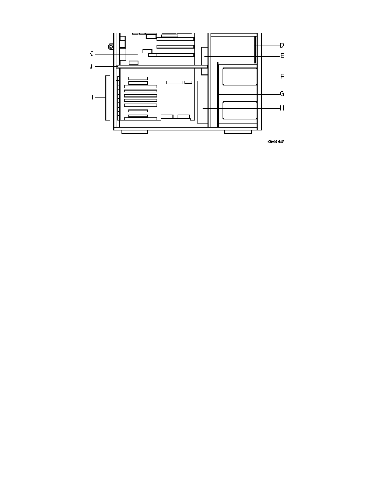
Figure 1-2. Server, Side View
A ¾ Power supply with integrated fan
B ¾ 3 1/2-inch diskette drive and vertical peripheral
bay
C ¾ Four, 5 1/4-inch external horizontal peripheral
bays
D ¾ Front panel board
E ¾ Fan 1
F ¾ Six, hot-docking vertical peripheral bays
G ¾ SCSI hot-docking backplane
H ¾ Fan 2 and card guide support panel
I ¾ Ten I/O expansion slot covers
J ¾ Module retaining bracket
K ¾ System board
Controls and Lights
Figure 1-3 shows the front panel door (opened), front panel, locations of server
controls and lights, four external peripheral bays, and the 3 1/2-inch diskette drive.
The controls and lights include:
Diskette drive ejector button: when pressed, ejects the disk.
Diskette drive activity light: when lit, indicates the drive is in use.
DC power push-button switch: when pressed, turns the system DC
Page 7

power on or off.
Reset push-button switch: when pressed, resets the system and
causes the power-on self test (POST) to run.
Front panel status lights:
Top light (power on/off): when lit, indicates the presence
of DC power in the system. The light goes out when the
power is turned off or the power source is disrupted.
Second light from top: when lit, indicates an IDE hard
disk drive or SCSI device on channel A is in use.
Third light from top: when lit, indicates a SCSI device on
channel B is in use.
Bottom light: when lit, indicates drive fault.
LCD panel: when enabled, displays system information.
Hot-docking bay status lights (one set per hard drive):
Left light: when on continuously, indicates drive present
and power on.
Middle light: when flashing, indicates drive activity.
Right light: when on continuously, indicates drive fault.
Page 8

A ¾ Diskette drive ejector button
B ¾ Diskette drive activity light
C ¾ DC power switch
D ¾ Reset switch
E ¾ Front panel status lights
F ¾ LCD display
G ¾ Hot-docking bay status lights
Server Security
The server system comes with a security key lock mounted in the upper front door
panel. The keys to the lock are in a plastic bag taped to the inside of the door.
Figure 1-3. Server Controls and Lights
To prevent unauthorized entry or use of the server, you can:
secure the side cover and the hot-docking bay metal door to the
chassis by inserting padlocks (not provided) through the metal tabs
protruding through slots in the cover and door
lock the front panel door to prevent access to the power and reset
push-button switches
set server administrative and user passwords
set secure mode to prevent keyboard or mouse input and to prevent
use of the front panel controls.
Use the System Configuration Utility (SCU) to:
enable the keyboard lockout timer so that the server requires a
password to reactivate the keyboard and mouse after a specified timeout period (1 to 128 minutes)
set an administrative password
set a user password
activate the secure mode hot-key
Page 9

disable writing to the diskette drive.
If you set the user password, but not the administrative password, the BIOS requires
you to enter the user password before you can boot the server or run the SCU. If you
set both passwords, entering either one lets you boot the server or enable the
keyboard and mouse. Only the administrative password lets you change the system
configuration with the SCU.
The secure boot mode allows the system to boot and run the operating system (OS).
However, you cannot use the keyboard or mouse until you enter the user password.
If you set a hot-key combination, you can secure the server immediately.
For additional security, two microswitches mounted on the floor plate of the server,
near the side cover and hot-docking bay door, transmit warnings to the system
board. Through software, they alert the user of unauthorized activity.
Figure 1-4. Server Security Locks
A ¾ Side cover lock
B ¾ Front panel door lock
C ¾ Inner door lock
Page 10

Power Supply
The auto-ranging 525 watt power supply, designed to minimize electromagnetic
interference (EMI) and radio frequency interference (RFI), provides sufficient power for
the system. The power supply automatically switches between these input voltage
ranges:
100-120 VAC at 50/60 Hz; 12 A maximum current
200-240 VAC at 50/60 Hz; 7 A maximum current
The power supply has three DC peripheral connectors for the accessible drive bays,
two mini-output connectors for use with the 3 1/2-inch diskette drives, one TTL output
connector for use with 5 1/4-inch peripherals or a
3 1/2-inch hard drive, and a separate connector that provides power directly to the
SCSI-2 SCA backplane.
An integral 35 cubic feet per minute (cfm) fan cools the power supply and helps to
cool the interior of the server.
EISA Expansion Slots
The six EISA bus slots on the system board provide for expansion and performance
enhancement. Two of these slots share a common chassis I/O expansion slot with
two of the PCI slots. If you use these EISA slots, you cannot use the PCI slots and
visa versa.
All six slots have the capability of being bus masters. When EISA masters arbitrate
for the bus, not all slots are created equal. The following pairs of slots share
arbitration requests: 1 and 2, 3 and 4, and 5 and 6. Therefore, in the scheme of
letting EISA masters take over the bus, ownership of it occurs in the following
sequence: 1, 2, 3, 4, 5, 6, 1, 2, 3, 4, 5, 6, 1, 2, 3, 4, 5, 6, etc.
The EISA bus, an extension of the Industry Standard Architecture (ISA) bus,
provides:
32-bit memory addressing
Type A transfers at 5.33 MB per second
Type B transfers at 8 MB per second
burst transfers at 33 MB per second
8-, 16-, or 32-bit data transfers
automatic translation of bus cycles between EISA and ISA masters
interrupt sharing.
Since EISA is fully backward compatible with ISA, you can install old or new ISA
Page 11

add-in boards and software in your server.
PCI Expansion Slots
The four PCI bus slots on the system board provide for expansion and performance
enhancement.
One slot is in line with a processor module slot; if you install a processor module in
this slot, you cannot use the PCI slot.
Two slots share a common chassis I/O expansion slot with two EISA slots. If you
use these PCI slots, you cannot use the EISA slots.
The 32-bit PCI bus is a two-segment PCI PeerBus that provides:
32- and 64-bit memory addressing
+ 5 V and + 3 V signaling environments
burst transfers at 133 MB per second
8-, 16-, or 32-bit data transfers
plug-and-play configuration
PCI PeerBus to maximize throughput.
Peripheral Bays
The server system contains a total of eleven peripheral bays.
The six 3 1/2-inch full-height hot-docking bays support industry
standard SCA SCSI hard disk drives. They allow easy setup of
Redundant Array of Inexpensive Disks (RAID) applications.
The four 5 1/4-inch half-height bays provide space for backup or
removable media devices.
The vertical 3 1/2-inch bay contains a 3 1/2-inch diskette drive that
supports both 720 KB and 1.44 MB media.
Onboard Super VGA Video Controller
The onboard, integrated Cirrus Logic CL-GD5424 super SVGA controller is fully
compatible with the CGA, EGA, Hercules Graphics, MDA, and VGA video standards.
The standard system configuration comes with 512 KB of onboard video memory,
allowing pixel resolutions of 640 x 480 and 800 x 600 in 256 colors, and 1024 x 768 x
16 colors. The SVGA controller supports only analog monitors (single and multiple
frequency, interlaced and noninterlaced) with a maximum vertical retrace interlaced
frequency of 87 Hz.
Page 12

By increasing the buffer size of the onboard video memory from 512 KB to 1 MB (with
one, 40-pin 256 K x 16, 70 ns fast-page DRAM), the controller can support 132column text modes and high resolution graphics with a maximum of 1024 x 768 x 64
K colors. It also provides hardware accelerated bit block transfers (BitBLT) of data.
SCSI Controller
The system board includes two PCI-based Adaptec AIC-7870 fast/wide SCSI-2
controllers (channels A and B) integrated as 32-bit PCI bus masters. The controllers
support data path widths of 8-bit (narrow SCSI) at a data transfer rate of 10 MB/sec
and 16-bit (wide SCSI) at a data transfer rate of 20 MB/sec. As PCI bus masters,
these controllers support data transfer rates of 133 MB/sec.
You can connect up to seven 8-bit narrow SCSI devices or up to fifteen 8-bit narrow
and/or 16-bit wide SCSI devices and one controller (maximum of seven 8-bit narrow
devices) to each channel. The devices include, for example, tape drives, printers,
optical media drives, and others.
The SCSI controller provides active negation outputs, controls for external differential
transceivers, a disk activity output, and a SCSI terminator power-down control.
Active negation outputs reduce the chance of data errors by actively driving both
polarities of the SCSI bus and avoiding indeterminate voltage levels and commonmode noise on long cable runs. The SCSI output drivers can directly drive a 48 mA,
single-ended SCSI bus with no additional drivers.
No additional logic, termination, or resistor loads are required to connect up to seven
8-bit narrow SCSI devices or up to fifteen 16-bit wide SCSI devices to each SCSI-2
channel on the system board.
SCSI-2 SCA-Compatible Backplane
The SCSI-2 SCA backplane for the ProServa PH is configured as two SCSI
continuous fast/wide SCSI buses (A and B) for connecting all hot-swap SCAcompatible hard drives installed in the hot-swap bays. This allows fast drive
installation and removal, as each hard drive plugs directly into a SCA connector on
the backplane. The backplane also acts as the termination point for all installed SCSI
hard drives and sets the hard drive IDs.
The backplane also supports up to three SCSI devices installed in the
5 1/4-inch bay, including the installed SCSI-2 CD-ROM reader. The SCSI-2 SCA
backplane supports fast/wide SCSI-2 (20 MB per second) data transfers to the 3 1/2inch hard drives. The backplane also supports SCSI-1 (5 MB per second) and
fast/narrow SCSI-2 (10 MB per second) devices. See Chapter 5, "SCSI Hot-docking
Backplane," for information on configuring the backplane.
ECC Memory Module
The server system comes with one ECC memory module installed. The module
provides up to 384 MB of high-speed memory (see Table 1-1 for system memory
configuration). If you need more memory, you can install an additional optional ECC
Page 13

memory module. The two modules provide up to 768 MB of high-speed memory.
Each module has three memory banks. Each bank consists of four SIMM sockets.
Each socket can hold an 8, 16, or 32 MB approved fast-page parity SIMM. You can
install any size SIMM in any bank but all four SIMMs in a bank must be the same
size. SIMM height must not exceed one inch; taller SIMMs will interfere with an
adjacent CPU module or ECC memory module.
The ECC memory module detects and corrects single-bit errors from DRAM
(Dynamic Random Access Memory) in real time, allowing your system to function
normally. It detects all double-bit errors but does not correct them. It also detects all
three-bit and four-bit adjacent errors in a DRAM nibble but does not correct them.
When one of these multiple-bit errors occurs, the ECC memory module generates an
NMI (NonMaskable Interrupt) and usually halts the system. The data transfer width of
the ECC memory module is 64/128 bits. It is compatible with all Pentium processor
modules.
The server supports both base (conventional) and extended memory. Base memory
is located at addresses 00000H to 9FFFFH (the first 640 KB). Extended memory
begins at address 100000H (1 M) and extends to the limit of addressable memory (4
G).
Some operating systems and application programs use base memory (for example,
MS-DOS, OS/2, and UNIX). Other operating systems use both conventional and
extended memory (for example, OS/2 and UNIX).
MS-DOS does not use extended memory. However, some MS-DOS utility programs
such as RAM disks, disk caches, print spoolers, and windowing environments use
extended memory for better performance.
CPU Module
The server system board accepts one or two CPU modules, each capable of
supporting one or two Pentium processors. Depending on system configuration, the
module(s) contain single or dual Pentium processors and a memory bus controller
(see Table 1-1 for system CPU module configurations).
The dual processor module provides a symmetric multiprocessing (SMP)
environment. In SMP, all processors are equal and have no preassigned tasks.
Distributing the processing loads between both processors increases system
performance. This is particularly useful when application demand is low and the I/O
request load is high. In the SMP environment, both processors share a common bus,
the same interrupt structure, and access to common memory and I/O channels. The
SMP implementation conforms to MP Specification Version 1.4.
The CPU modules are compatible with all 32-bit software written for the Intel386Ô ,
Intel486Ô , and Intel Pentium processors. Operating system support includes Novell
NetWare, MS-DOS, and Windows NT.
The single Pentium processor module uses the Intel 82497 cache controller and Intel
82492 SRAM components to provide 512 KB of zero wait state two-way associative
cache.
The dual Pentium processor module uses the Intel 82498 cache controller and Intel
82493 SRAM components to provide 1 MB of zero wait state two-way associative
Page 14

cache for each processor.
Contact your NEC sales representative or dealer for a list of CPU modules available
for your server.
EtherExpress PCI PRO 100B LAN Adapter Board
The Intel EtherExpress PCI PRO 100B local area network (LAN) Adapter board
(standard on all configurations except base) connects to your local network via
unshielded twisted pair (UTP) wire. The UTP connects to a single RJ-45 connector on
the adapter board at the back of the system.
The PRO 100B Adapter board and supporting software extends the performance of
the ProServa PH servers onto the LAN. A 32-bit architecture and features like Early
Receive Interrupt and Suspend/Resume ensure that data flows at top speeds on and
off the LAN. Additionally, as the PRO 100B high performance capabilities minimize
use of the server's processor, the ProServa PH has more computing power for even
the most demanding applications and operating environments.
The 100-MB adapter board runs at 10 Mbps or 100 Mbps, depending on the speed of
the hub port to which the adapter is attached. This permits the server to take full
advantage of its high performance, high speed PCI bus.
The Adapter board is switchless and is Plug and Play compatible. The board has 16
KB of onboard memory, an Intel 82556 controller, uses INTA interrupt levels, and
incorporates a Bus Master DMA data transfer mode.
A link (LNK) LED on the board indicates when the adapter is connected to a hub or
switch and is receiving link pulses. An activity (ACT) LED on the board indicates
read/write activity on the network. A lit yellow LED indicates that the board is
operating at 10 Mbps and a lit green LED indicates that the board is operating at 100
Mbps. The adapter auto-detects 10 or 100 Mbps operation.
Additional information on the adapter is given in the help files included with the board
and in Appendix I, "PRO 100B LAN Adapter Board."
CD-ROM Reader
All servers except the base configurations ship with a quad-speed SCSI-2 CD-ROM
reader installed in the bottom slot of the 5 1/4-inch accessible bay. The reader is
used to load and start programs from a CD disc.
CD-ROM operational information is given in Section 2, "Installing Your Server."
Connector and jumper information is included in Appendix F, "Quad-Speed CD-ROM
Reader."
LANDesk Server Monitor Module
The LANDesk Server Monitor Module (standard on high availability configurations,
optional on all others) is a hardware/software server management application (for use
with Novell NetWare 3.1x or 4.x). The application monitors the behavior of your server
over a network or an optional modem. The Server Monitor Module monitors over a
hundred different server parameters. This allows you to identify trends, both positive
Page 15

and negative, on server behavior.
You can track such parameters as CPU use, disk reads, and cache buffers. You can
also monitor server physical parameters (temperature, power supply voltage) and
receive information about server status, even when the server or network is down. If
you add a PCMCIA modem to the serial port of the server monitor module, you can
monitor, configure, and set up the server from a remote site.
The Server Monitor Module works in conjunction with the Interrupt Controller APIC on
the system's board but works independent of the LANDesk Server Control shipped
with your server. LANDesk Server Control allows server monitoring and control at the
server itself.
CAUTION
If you are using both applications, you should use caution
in your settings as the two applications do not interact
together. See Appendix E, "LANDesk Server Control," for
application interaction and a comparison between the
LANDesk Server Monitor Module and LANDesk Server
Control.
The LANDesk Server Monitor Module consists of Server Monitor software, a Monitor
Module ISA board with a rechargeable battery backup power source, and a thermal
probe. The Monitor Module board plugs into one of the EISA/ISA expansion board
slots in your server. The probe is used to monitor critical temperatures, and can be
positioned in a location of your choice.
For details on the installation and use of the LANDesk Server Monitor Module and
thermal probe, refer to the documentation included with the Module.
Mylex Disk Array Controller
The Mylex Disk Array Controller (standard on high availability configurations, optional
on all others) is a caching PCI SCSI Redundant Array of Independent Disks (RAID)
controller that provides a data redundancy technique for distributing data across hard
drives. The array controller supports RAID levels 0, 1, and 5.
The controller uses this technology to connect up to seven SCSI hard disk drives
simultaneously on each of up to two channels. This allows continued operation of the
server without loss of data if a hard drive fails. If a drive fails, read and write requests
are serviced by standby hot-spare drives in the array.
For further information on the Disk Array Controller, including installation and
operation procedures, refer to the Mylex Disk Array Controller User's Manual supplied
with the controller.
Network Applications Software
All server configurations come with the following Intel network application software
ready for installation on your system:
LANDesk Management Suite
Page 16

LANDesk Server Control.
Both applications require loading on your system's hard disk, and can only be used
with Novell NetWare 3.1x or 4.x. See the application's documentation for complete
installation and operation procedures.
Each application is briefly described in the following paragraphs.
LANDesk Management Suite
All server configurations come with the Intel LANDesk Management Suite. The
LANDesk Management Suite consists of four categories of network tools:
workstation management tools – enables you to easily manage the
workstations on your network
server management tools – enables you to manage the file servers on
your network
wire management tools – enables you to monitor the traffic on your
network
network services tools – provides services on your network or enables
you to manage the services available on your network.
The Workstation Management tools include Software Metering, Software Distribution,
Desktop Manager, and Desktop Remote modules. The Software Metering module
allows you to monitor and control license limits for network applications. The
Software Distribution module allows you to easily distribute software to workstations
on your local area network from a central location. The Desktop Manager module
allows you to remotely access and obtain diagnostic information about the
workstations on your network. The Desktop Remote module gives you complete
control of a Windows workstation from a remote location through a modem and
phone line.
The Server Management tools include Server Monitor and Server Status modules.
The Server Monitor module tracks and graphs server parameters. The Server Status
module monitors the binderies of up to eight types of servers, either individually or all
eight at once.
The Wire Management tools includes a Traffic Monitor, Performance Monitor, and
Software Probe. The Traffic Monitor tracks and displays network traffic information.
The Performance Monitor tracks network traffic to provide statistical information about
what applications are running on the network. The Software Probe gathers data for
the traffic monitor and performance monitor.
The Network Services tools includes a Virus Scan tool, Network Printer Manager,
and Queue Monitor. The Virus Scan tool allows automatic scanning of all workstation
hard disks and server volumes. The Network Printer Manager provides access and
management of all network printers run under Windows. The Queue Monitor manages
network print queues.
For installation and operating details, refer to the included LANDesk Management
Page 17

Suite documentation.
LANDesk Server Control
All server configurations come with the Intel LANDesk Server Control application (for
use with Novell NetWare 3.1x or 4.x only), ready for installation on your system. The
Server Control application software operates as a background task that continuously
monitors the system until an error event occurs.
The Server Control application monitors and controls critical system hardware
conditions on the ProServa PH server. The INCA component on the baseboard
provides access to information such as temperature, voltage, chassis intrusion
(where applicable), and cooling fan status.
The application makes this information available locally through the Server Control's
Local Console and remotely through Simple Network Management Protocol (SNMP).
The Local Console allows you to set monitoring thresholds on this data to
automatically broadcast an alert, display a message, beep the speaker, initiate a
shut-down, or hard reset the system.
The LANDesk Server Control application also controls the INCA watchdog timer that
is used to automatically reboot the server after a system crash.
Major components of the LANDesk Server Control include the Local Console
Application and the SNMP Translator. The Local Console Application provides the
user interface for setting thresholds, reading current status, and setting events for
Server Control. The Application uses the Management Interface of the service layer
for low-level interactions with the system management hardware.
The SNMP Translator is a service layer management application and a sub-agent of
the NetWare Extensible SNMP agent. It also uses the service layer to get and set
management data.
For installation and operating details, refer to the "LANDesk Server
Control - Getting Started Guide," the electronic help files provided with the Server
Control, and Appendix E, "LANDesk Server Control," in this guide.
System Expansion
As application requirements increase, you can expand the server with the following
options:
additional memory
Pentium processor upgrades
storage devices (tape drive, CD-ROM, diskette drive, hard disk drives)
Intel EtherExpress PRO/100 LAN Adapter board (standard on network
ready and high capacity configurations)
LANDesk Server Monitor Module (standard on high capacity
configurations)
Page 18

Mylex Disk Array RAID Controller (standard on dual and quad
processor high availability configurations).
Descriptions of the adapter board, monitor module, and RAID controller are included
earlier in this chapter.
Memory Expansion
All servers except the quad-processor configurations come standard with one
memory module containing 32 MB (four 8-MB SIMMs) of high speed SIMM memory.
The network ready and high availability quad-processor configurations come standard
with one memory module containing 64 MB (eight 8-MB SIMMs) of SIMM memory.
Memory can be expanded up to 384 MB on a single module or up to 768 MB using
two modules. Optional SIMMs are installed in SIMM sockets on the memory
modules. Optional 8-, 16-, and 32-MB SIMMs (36-bit, 70 ns) are available from NEC.
See Chapter 7, "Installing System Options," for further information and installation
instructions.
Storage Device Expansion
The server supports optional IDE storage devices, fast/narrow SCSI-2 devices, or
fast/wide SCSI-2 devices, including:
up to four 5 1/4-inch form factor IDE or SCSI storage devices (diskette,
hard disk drive, tape, CD-ROM) in the top front panel bay
up to six 3 1/2-inch, 1-inch height, SCSI-2 SCA hard disk drives in the
bottom front hot swap bay.
See Chapter 4, "Taking Your System Apart," for information on installing optional 5
1/4-inch storage devices. See Chapter 6, "Hot Swapping SCSI Hard Drives," for
information on installing and swapping hard drives.
BIOS and System Configuration Utility
Hardware configuration takes place during the BIOS Power-On-Self-Test (POST) and
PCI and ISA Plug-and-Play auto configuration. You can modify the hardware
configuration using the bootable System Configuration Utility (SCU).
The SCU displays a series of system parameters, including system memory, IDE
controller, SCSI controller, serial and parallel ports, and passwords. You can select
the appropriate option of each parameter for your application. When finished, save the
configuration to CMOS RAM and NVRAM. The system reboots with the new
configuration parameters.
Table 1-3 summarizes BIOS and SCU features. See Chapter 3, "Using System
Utilities," for information on using the SCU.
Table 1-3. BIOS and SCU Feature Summary
Page 19

Feature Description
Error detection During initialization, system emits beep codes (before video
Critical event logging Provides information for applications and drivers, such as POST
Security The SCU provides several ways to secure the system.
Boot sequence control Offers choice of booting from diskette or hard drive or both in a
BIOS recovery Allows booting from a diskette if BIOS ROM is corrupted, and
BIOS update Flash Memory Update (FMUP) utility updates BIOS with a new
Language update Flash Language Update (FLUP) utility installs versions of the
Custom logo Enables creating and displaying a custom logo when SCU is
initialization) and displays messages to identify problem.
error codes, date/time area was last erased, and identification of
failed SIMMs.
User password enables viewing SCU configuration.
Administrator password enables changing
configuration.
Inactivity timer blanks screen and inhibits keyboard
and mouse after specified time elapses.
Hot-key immediately blanks screen and inhibits
keyboard and mouse.
specified order.
automatically reinstalls BIOS.
version from diskette.
BIOS and SCU in languages other than English.
executed from diskette.
See Chapter 3, "Using System Utilities," for additional information on using the SCU,
recovering the BIOS, and updating the BIOS.
 Loading...