

Page 1

Projector
PE506UL/PE456USL/PE506WL/
PE456WSL
User’s Manual
Please visit our web site for User’s Manual in the latest version:
https://www.sharp-nec-displays.com/dl/en/pj_manual/lineup.html
Model No.
NP-PE506UL/NP-PE456USL/NP-PE506WL/NP-PE456WSL
Page 2

Ver. 3 07/22
Trademarks
• AccuBlend and MultiPresenter are trademarks or registered trademarks of Sharp NEC Display Solutions, Ltd. in
Japan, in the United States and other countries.
• Apple and Mac are trademarks of Apple Inc. registered in the U.S. and other countries.
• Microsoft and Windows are either a registered trademark or trademark of Microsoft Corporation in the United
States and/or other countries.
• Micro Saver is a registered trademark of Kensington Computer Products Group, a division of ACCO Brands in the
U.S. and other countries.
• The terms HDMI and HDMI High-Definition Multimedia Interface, and the HDMI Logo are trademarks or registered
trademarks of HDMI Licensing Administrator, Inc. in the United States and other countries.
• PJLink trademark and logo are trademarks applied for registration or are already registered in Japan, the United
States of America and other countries and areas.
• Blu-ray is a trademark of Blu-ray Disc Association.
• CRESTRON and ROOMVIEW are registered trademarks of Crestron Electronics, Inc. in the United States and other
countries.
• Other product names and logos mentioned in this user’s manual may be the trademarks or registered trademarks
of their respective holders.
• GPL/LGPL Software Licenses
The product includes software licensed under GNU General Public License (GPL), GNU Lesser General Public
License (LGPL), and others.
For more information on each software, see “readme.pdf” in the “about GPL&LGPL” folder on the supplied CD-
ROM.
NOTES
(1) The contents of this user’s manual may not be reprinted in part or whole without permission.
(2) The contents of this user’s manual are subject to change without notice.
(3) Great care has been taken in the preparation of this user’s manual; however, should you notice any questionable
points, errors or omissions, please contact us.
(4) Notwithstanding article (3), NEC will not be responsible for any claims on loss of profit or other matters deemed
to result from using the Projector.
(5) This manual is commonly provided to all regions so they may contain descriptions that are pertinent for other
countries.
(6) PE506UL/PE506WL and PE456USL/PE456WSL differ only in the appearance of the lens. Unless it involves the
introduction of lens-related functions, the drawings of other projector cabinets are shown with PE506UL as an
example.
Page 3
Important Information
Important Information
Safety Cautions
Precautions
Please read this manual carefully before using your NEC projector and keep the manual handy for future reference.
CAUTION
To turn off main power, be sure to remove the plug from power outlet.
The power outlet socket should be installed as near to the equipment as possible, and should be easily
accessible.
CAUTION
TO PREVENT SHOCK, DO NOT OPEN THE CABINET.
THERE ARE HIGH-VOLTAGE COMPONENTS INSIDE.
REFER SERVICING TO QUALIFIED SERVICE PERSONNEL.
This symbol warns the user that uninsulated voltage within the unit may be sufficient to cause electrical
shock. Therefore, it is dangerous to make any kind of contact with any part inside of the unit.
This symbol alerts the user that important information concerning the operation and maintenance of this
unit has been provided.
The information should be read carefully to avoid problems.
WARNING: TO PREVENT FIRE OR SHOCK, DO NOT EXPOSE THIS UNIT TO RAIN OR MOISTURE.
DO NOT USE THIS UNIT’S PLUG WITH AN EXTENSION CORD OR IN AN OUTLET UNLESS ALL THE PRONGS
CAN BE FULLY INSERTED.
Machine Noise Information Regulation - 3. GPSGV,
The highest sound pressure level is less than 70 dB (A) in accordance with EN ISO 7779.
CAUTION
Avoid displaying stationary images for a prolonged period of time.
Doing so can result in these images being temporarily sustained on the surface of the LCD panel.
If this should happen, continue to use your projector. The static background from previous images will
disappear.
Disposing of your used product
In the European Union
EU-wide legislation as implemented in each Member State requires that used electrical and electronic
products carrying the mark (left) must be disposed of separately from normal household waste. This includes projectors and their electrical accessories. When you dispose of such products, please follow the
guidance of your local authority and/or ask the shop where you purchased the product.
After collecting the used products, they are reused and recycled in a proper way. This effort will help us
reduce the wastes as well as the negative impact to the human health and the environment at the minimum level.
The mark on the electrical and electronic products only applies to the current European Union Member
States.
Outside the European Union
If you wish to dispose of used electrical and electronic products outside the European union, please
contact your local authority and ask for the correct method of disposal.
For EU: The crossed-out wheeled bin implies that used batteries should not be put to the general household
waste! There is a separate collection system for used batteries, to allow proper treatment and recycling
in accordance with legislation.
According to EU directive 2006/66/EC, the battery can’t be disposed improperly. The battery shall
be separated to collect by local service.
I
Page 4
Important Information
FCC Information (for USA only)
WARNING
• The Federal Communications Commission does not allow any modifications or changes to the unit EXCEPT those
specified by Sharp NEC Display Solutions of America, Inc. in this manual. Failure to comply with this government
regulation could void your right to operate this equipment.
• This equipment has been tested and found to comply with the limits for a class A digital device, pursuant to Part
15 of the FCC Rules. These limits are designed to provide reasonable protection against harmful interference when
the equipment is operated in a commercial environment. This equipment generates, uses, and can radiate radio
frequency energy and, if not installed and used in accordance with the instruction manual, may cause harmful
interference to radio communications. Operation of this equipment in a residential area is likely to cause harmful
interference in which case the user will be required to correct the interference at his own expense.
Supplier’s declaration of conformity (for USA only)
This device complies with Part 15 of the FCC Rules. Operation is subject to the following two conditions.
(1) This device may not cause harmful interference, and (2) this device must accept any interference received, including interference that may cause undesired operation.
U.S.Responsible Party: Sharp NEC Display Solutions of America, Inc.
Address: 3250 Lacey Rd, Ste 500
Downers Grove, IL 60515
Telephone Number: 630-467-3000
Type of Product: Projector
Equipment Classification: Class A Peripheral
Model Number: NP-PE506UL/NP-PE456USL/NP-PE506WL
For UK only: In UK, a BS approved power cord with moulded plug has a Black (five Amps) fuse installed for use with
this equipment. If a power cord is not supplied with this equipment please contact your supplier.
NOTE:
• UKCA is for PE506UL/PE506WL model only.
(For Germany only)
Machine Noise Information Regulation - 3. GPSGV,
The highest sound pressure level is less than 70 dB (A) in accordance with EN ISO 7779.
Information of the AUDIO OUT mini jack
The AUDIO OUT mini jack does not support earphone/headphone terminal.
II
Page 5
Important Information
(For Customers in U.K.)
IMPORTANT
• The wires in this mains lead are coloured in accordance with the following code:
GREEN-AND-YELLOW: “Earth”
BLUE: “Neutral”
BROWN: “Live”
• As the colours of the wires in the mains lead of this apparatus may not correspond with the coloured markings
identifying the terminals in your plug proceed as follows:
• The wire which is coloured GREEN-AND-YELLOW must be connected to the terminal in the plug which is marked
by the letter E or by the safety earth symbol or coloured green or green-and-yellow.
• The wire which is coloured BLUE must be connected to the terminal which is marked with the letter N or co-
loured black.
• The wire which is coloured BROWN must be connected to the terminal which is marked with the letter L or
coloured red.
• Ensure that your equipment is connected correctly. If you are in any doubt consult a qualified electrician.
“WARNING: THIS APPARATUS MUST BE EARTHED.”
Important Safeguards
These safety instructions are to ensure the long life of your projector and to prevent fire and shock. Please read
them carefully and heed all warnings.
Installation
• Do not place the projector in the following conditions:
- on an unstable cart, stand, or table.
- near water, baths, or damp rooms.
- in direct sunlight, near heaters, or heat radiating appliances.
- in a dusty, smoky or steamy environment.
- on a sheet of paper or cloth, rugs or carpets.
• Avoid locations with extremes of temperature and humidity.
The usage environment of this projector is as follows.
- The operating temperature: 0° to 40°C (32° to 104° F) / humidity: 20 to 80% (with no condensation)
- The storage temperature: –10°C to 50°C (14 to 122°F) / humidity: 20 to 80% (with no condensation)
• If you wish to have the projector installed on the ceiling:
- Do not attempt to install the projector yourself.
- The projector must be installed by qualified technicians in order to ensure proper operation and reduce the risk
of bodily injury.
- In addition, the ceiling must be strong enough to support the projector and the installation must be in accordance
with any local building codes.
- Please consult your dealer for more information.
• Do not install and store the projector in the below circumstances. Failure to do so may cause of malfunction.
- In powerful magnetic fields
- In corrosive gas environment
- Outdoors
• If intense light like laser beams enters from the lens, it could lead to malfunction.
CAUTION
This equipment is designed to be used in the condition of the power cord connected to earth. If the
power cord is not connected to the earth, it may cause electric shock. Please make sure the power
cord is earthed properly.
Do not use a 2-core plug converter adapter.
Cable information
CAUTION
Use shielded cables or cables attached ferrite cores so as not to interfere with radio and television
reception. For details, please refer to “Making Connections” in this user’s manual.
III
Page 6
Important Information
Notice Concerning Electromagnetic Interference (EMI)
WARNING:
Operation of this equipment in a residential environment could cause radio interference.
WARNING
• Operation of this equipment in a residential environment could cause radio interference.
• Do not cover the lens with the lens cap or equivalent while the projector is on. Doing so can lead to melting
of the cap due to the heat emitted from the light output.
• Do not place any objects, which are easily affected by heat, in front of the projection lens. Doing so could lead
to the object melting from the heat that is emitted from the light output.
• Do not use a spray containing flammable gas to get rid of accumulated dust and dirt on the filter and the
projection window. It may cause of fire.
Fire and Shock Precautions
• Ensure that there is sufficient ventilation and that vents are unobstructed to prevent the build-up of heat inside
your projector. Allow at least 4 inches (10 cm) of space between your projector and a wall.
• Prevent foreign objects such as paper clips and bits of paper from falling into your projector. Do not attempt to
retrieve any objects that might fall into your projector. Do not insert any metal objects such as a wire or screwdriver
into your projector. If something should fall into your projector, disconnect it immediately and have the object
removed by a qualified service personnel.
• Do not place any objects on top of the projector.
• Do not touch the power plug during a thunderstorm. Doing so can cause electrical shock or fire.
• The projector is designed to operate on a power supply of 100-240V AC 50/60 Hz. Ensure that your power supply
fits this requirement before attempting to use your projector.
• About the projector’s light source
- Do not look into the projector’s lens.
Strong light that could damage your eyes is projected when the projector is operating. Be especially careful
when children are around.
- Do not look at the projected light using optical devices (magnifying glasses, reflectors, etc.). Doing so could
result in vision impairment.
- Check that there is no one looking at the lens within the projection range before turning on the projector.
- Do not allow children to operate the projector alone. When a child is operating the projector an adult should
always be present and watch the child carefully.
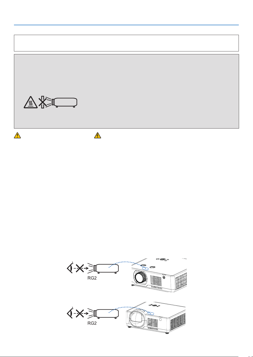
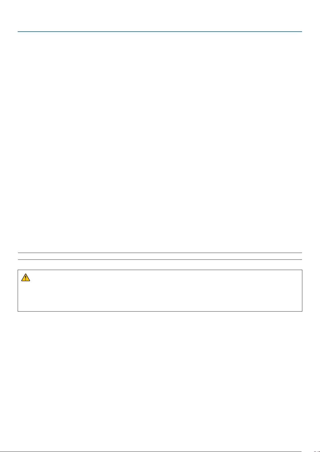
- The below pictogram, that is indicated near the lens on the cabinet, describes this projector is categorized in
the risk group 2 of IEC/EN 62471-5:2015. As with any bright light source, do not stare into the beam, RG2 IEC/
EN 62471-5:2015.
(Model for PE506UL and PE506WL only)
(Model for PE456USL and PE456WSL only)
IV
Page 7
Important Information
• Keep any items such as magnifying glass out of the light path of the projector. The light being projected from the
lens is extensive, therefore any kind of abnormal objects that can redirect light coming out of the lens, can cause
unpredictable outcome such as fire or injury to the eyes.
• Do not place any objects, which are easily affected by heat, in front of a projector exhaust vent.
Doing so could lead to the object melting or getting your hands burned from the heat that is emitted from the
exhaust.
• Do not splash water over the projector. Doing so can cause electrical shock or fire. If the projector gets wet, turn
off the projector, unplug the power cord and have the projector serviced by a qualified service personnel.
• Handle the power cord carefully. A damaged or frayed power cord can cause electric shock or fire.
- Do not use any power cord other than the one supplied with the projector.
- Do not bend or tug the power cord excessively.
- Do not place the power cord under the projector, or any heavy object.
- Do not cover the power cord with other soft materials such as rugs.
- Do not heat the power cord.
- Do not handle the power plug with wet hands.
• Turn off the projector, unplug the power cord and have the projector serviced by a qualified service personnel
under the following conditions:
- When the power cord or plug is damaged or frayed.
- If liquid has been spilled into the projector, or if it has been exposed to rain or water.
- If the projector does not operate normally when you follow the instructions described in this user’s manual.
- If the projector has been dropped or the cabinet has been damaged.
- If the projector exhibits a distinct change in performance, indicating a need for service.
• Disconnect the power cord and any other cables before carrying the projector.
• Turn off the projector and unplug the power cord before cleaning the cabinet.
• Turn off the projector and unplug the power cord if the projector is not to be used for an extended period of time.
• When using a LAN cable:
For safety, do not connect to the terminal for peripheral device wiring that might have excessive voltage.
• Lens shift, focus and zoom operations.
- When shifting the lens or adjusting the focus or zoom, do so from either behind or to the side of the projector.
If these operations are performed from the front, your eyes could be exposed to strong light and get injured..
- Keep your hands away from the lens area when performing the lens shift operation. If not, your fingers could get
caught in the cap between the cabinet and the lens.
NOTE: [Lens shift] functions are only available for PE506UL/PE506WL.
CAUTION
• Do not use the adjustable tilt foot for purposes other than originally intended. Misuses such as gripping the
tilt-foot or hanging on the wall can cause damage to the projector.
• Do not turn off the AC power for 60 seconds after the light source is turned on and while the POWER indicator
is blinking blue. Doing so could cause premature Light failure.
Remote Control Precautions
• Handle the remote control carefully.
• If the remote control gets wet, wipe it dry immediately.
• Avoid excessive heat and humidity.
• Do not short, heat, or take apart batteries.
• Do not throw batteries into fire.
• If you will not be using the remote control for a long time, remove the batteries.
• Ensure that you have the batteries’ polarity (+/−) aligned correctly.
• Do not use new and old batteries together, or use different types of batteries together.
• Dispose of used batteries according to your local regulations.
V
Page 8

Laser Safety Caution
!
Important Information
CLASS 1 OF IEC 60825-1 THIRD EDITION LASER PRODUCT
• The laser module is equipped in this product. Use of controls or adjustments of procedures other than those
For USA
COMPLIES WITH 21 CFR 1040.10 AND 1040.11 EXCEPT FOR CONFORMANCE AS A RISK GROUP 2 LIP AS DEFINED IN IEC/EN 62471-5:ED.1.0. FOR MORE INFORMATION SEE LASER NOTICE NO. 57, DATED MAY 8, 2019.
For other regions (including USA)
This product is classified as Class 1 of IEC 60825-1 Third edition 2014-05 and RG2 of IEC/EN 62471-5 First edition
2015-06.
• Obey the laws and regulations of your country in relation to the installation and management of the device.
• Outline of laser emitted from the built-in light module:
• Radiation pattern from the protective housing:
19.04mW(PE456USL/PE456WSL)
The laser module is equipped in this product. Use of controls or adjustments of procedures other than those
specified herein may result in hazardous radiation exposure.
WARNING
specified herein may result in hazardous radiation exposure.
Wave length: 449-461nm
Maximum power: 105W
Wave length: 449-461nm
Maximum laser radiation output: 66.6mW(PE506UL/PE506WL)
Light Module
• A light module containing multiple laser diodes is equipped in the product as the light source.
• These laser diodes are sealed in the light module. No maintenance or service is required for the performance
of the light module.
• End user is not allowed to replace the light module.
• Contact qualified distributor for light module replacement and further information.
VI
Page 9
I
Important Information
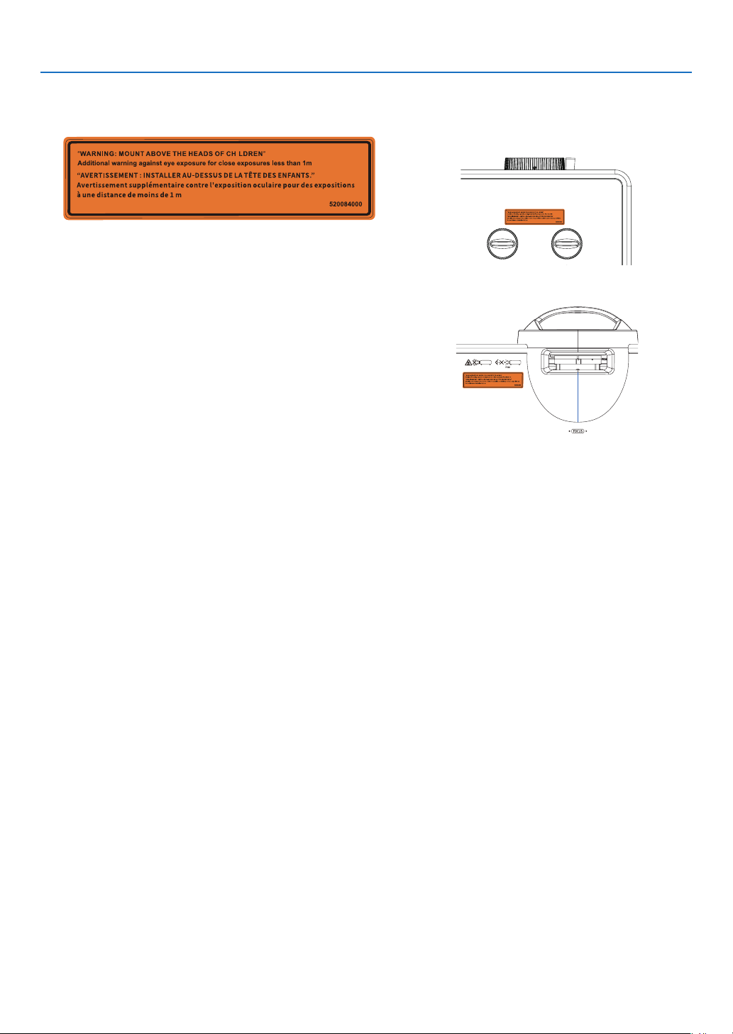
• As with any bright light source, do not stare into the beam, RG2 IEC/EN 62471-5:2015.
Label 1
FDA additional warning label (For USA only)
I
• The laser module is equipped in this product Use of controls or adjustments of procedures other than those
specified herein may result in hazardous radiation exposure.
• Additional instructions to supervise children, no staring, and not use optical aids.
• Notice is given to supervise children and to never allow them to stare into the projector beam at any distance
from the projector.
• Notice is given to use caution when using the remote control for starting the projector while in front of the
projection lens.
• Notice is given to the user to avoid the use of optical aids such as binoculars or telescopes inside the beam.
• When turning on the projector, make sure no one within projection range is looking at the lens.
• Keep any items (magnifying glass etc.) out of the light path of the projector. The light path being projected
from the lens is extensive, therefore any kind of abnormal objects that can redirect light coming out of the lens.
can cause an unpredictable outcome such as a fire or injury to the eyes.
• WARNING:MOUNT ABOVE THE HEADS OF CHILDREN.
The use of a ceiling mount is recommended with this product to place it above the eyes of children.
• Any operation or adjustment not specifically instructed by the user's guide creates the risk of hazardous
radiation.
[PE506UL/PE506WL]
I
[PE456USL/PE456WSL]
VII
Page 10
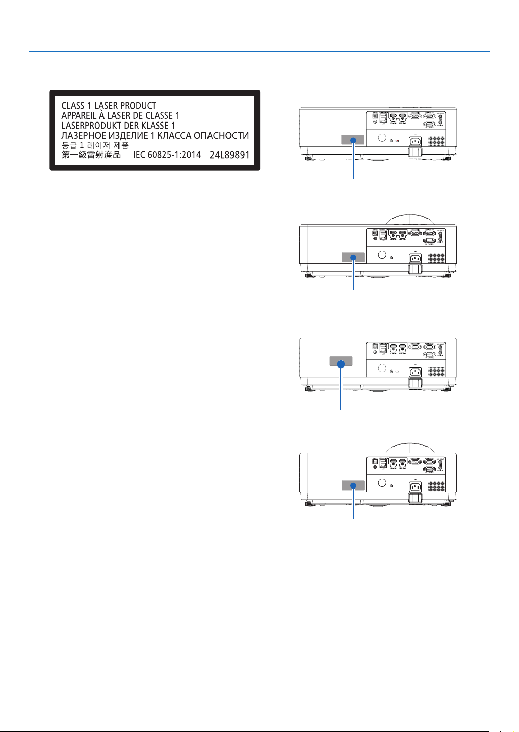
Label 2
Class 1 laser product label (For other regions)
Important Information
For USA
[PE506UL/PE506WL]
Label 2
[PE456USL]
Label 2
For other regions
[PE506UL/PE506WL]
Label 2
[PE456USL/PE456WSL]
Label 2
VIII
Page 11
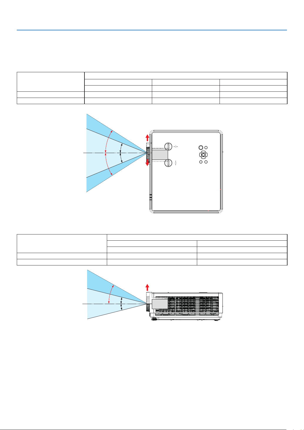
Laser light radiation range
The figure below shows the maximum radiation range of the laser light.
[PE506UL/PE506WL]
Horizontal angle (unit: degree)
Lens position
Zoom
Wide 33.0 22.3 33.0
Tele 21.8 14.2 21.8
Right most Center (Reference value) Left most
HR HC HL
Important Information
Vertical angle (unit: degree)
Zoom
Wide 29.5 14.4
Tele 19.2 9.0
HR
HL
VU
Right
HC
HC
Left
Lens position
Upper most Center (Reference value)
VU VC
Upper
VC
VC
IX
Page 12
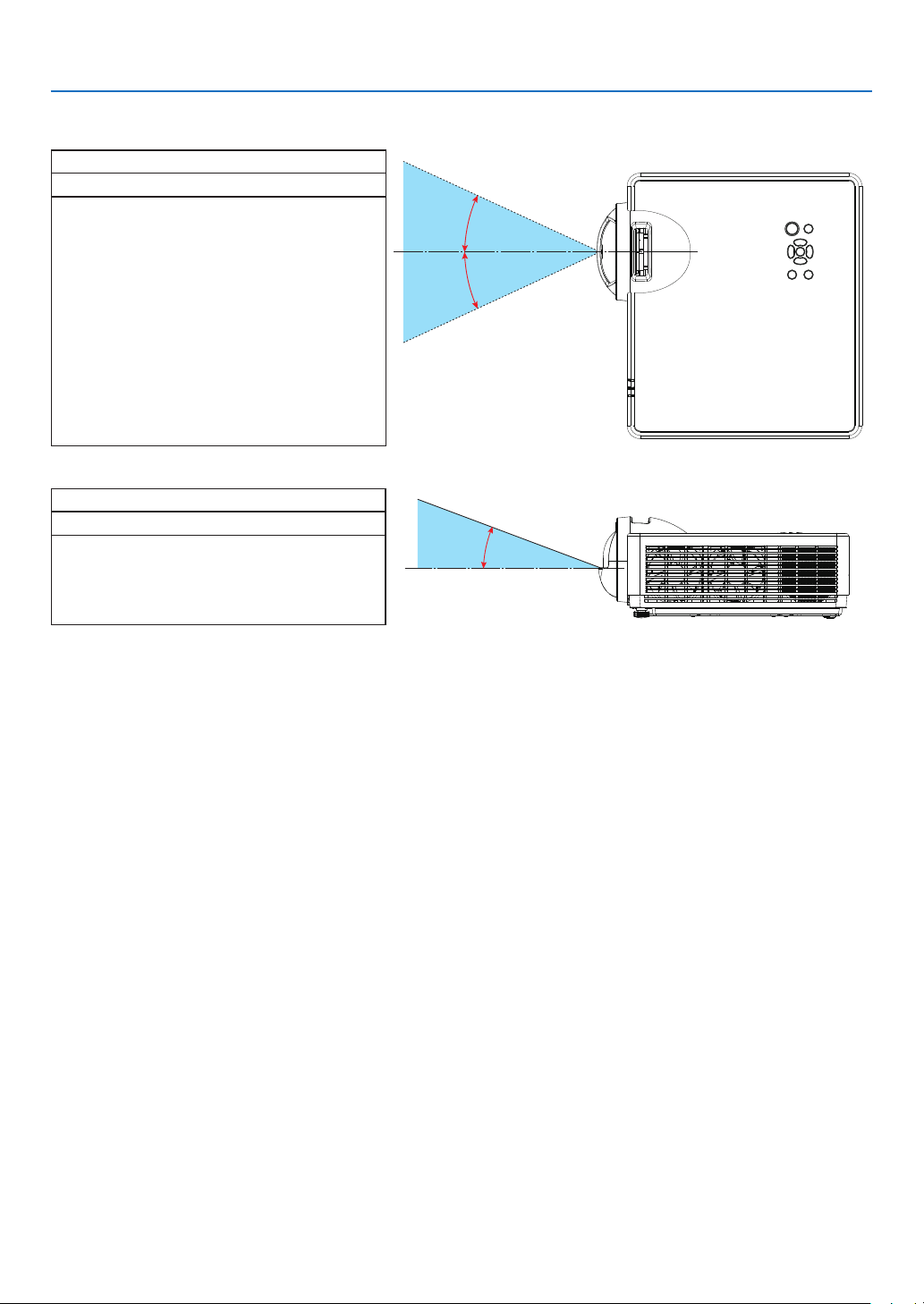
[PE456USL/PE456WSL]
Horizontal angle (unit: degree)
Lens position
HC
49.0
Vertical angle (unit: degree)
Lens position
VC
55.2
Important Information
HC
HC
VC
X
Page 13
Important Information
About High Altitude mode
• Set [High altitude] to [ON] in the Setting menu when using the projector at altitudes approximately 1700
meters / 5577 feet or higher.
Using the projector at an altitude of about 1700 meters / 5577 feet or more without setting [High altitude] to
[ON] can cause the projector to overheat and shut down the protector.
• Using the projector at altitudes approximately 1700 meters / 5577 feet or higher can shorten the life of optical
components such as the light module.
• When the projector is at altitudes approximately 1700 meters / 5577 feet or higher, it will switch from [OFF] to
[ON]automatically.
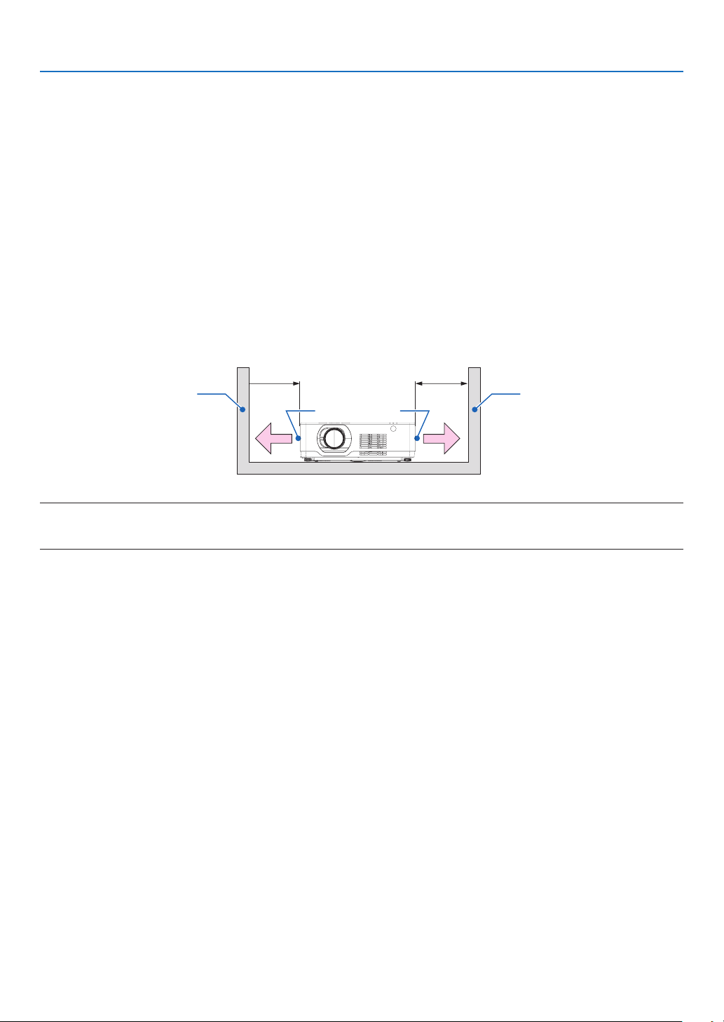
Clearance for Installing the Projector
When installing the projector, keep sufficient space around it, as described below. If not, the hot exhaust emitted
from the projector may be taken back in.
Also, make sure no wind from an air-conditioner hits the projector. The projector’s heat control system may detect
an abnormality (temperature error) and automatically shut off the power.
20 cm/8" or greater20 cm/8" or greater
Wall
Intake
vent
Exhaust
vent
Wall
NOTE:
In the above figure, it is assumed that there is sufficient space above the projector. There is also an intake vent in the front. Leave about
10 cm or more space behind, and even more space for installing the cables.
Precautions for Ceiling Installation
Do not install the projector in the following places. Attached substances such as oil, chemicals and
moisture may cause deformation or cracks of the cabinet, corrosion of the metal parts, or malfunction.
• Outdoors and places with humid or dust.
• Places exposed to oil smoke or steam.
• Places where corrosive gases are generated.
About Copyright of original projected pictures:
Please note that using this projector for the purpose of commercial gain or the attraction of public attention in a venue
such as a coffee shop or hotel and employing compression or expansion of the screen image with the following
functions may raise concern about the infringement of copyrights which are protected by copyright law.
[ASPECT], [KEYSTONE], Magnifying feature and other similar features.
Turkish WEEE information relevant for Turkish market
AEEE Yonetmeliğine Uygundur.
This device is not intended for use in the direct field of view at visual display workplaces. To avoid incommoding
reflections at visual display workplaces this device must not be placed in the direct field of view.
Power management function
The projector has power management functions. To reduce power consumption, the power management functions
(1 and 2) are factory preset as shown below. To control the projector from an external device via serial cable connection, use the on-screen menu to change the settings for 1 and 2.
XI
Page 14
竖向 360°
横向 360°
竖向 360°
Important Information
1. STANDBY MODE (Factory preset: NORMAL)
To control the projector from an external device, select [NETWORK STANDBY] or [SLEEP] for [STANDBY MODE].
NOTE:
• When [NORMAL] is selected for [STANDBY MODE], the following terminals and functions will not work:
MONITOR OUT terminal, AUDIO OUT terminal, LAN functions. Please refer to page 39 about details.
2. Power management (Factory preset: Ready)
To control the projector from an external device, select [OFF] for [Power management].
NOTE:
• When [5 Min] is selected for [Timer], you can enable the projector to automatically turn off in 5 Min if there is no signal received by any
input or if no operation is performed.
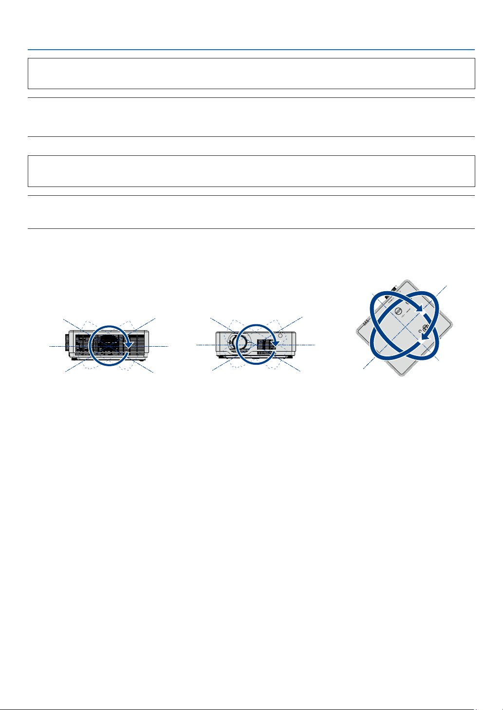
360° projection function
Our projector support 360° projection.
退出
EXIT
决定
ENTER
信号源
SOURCE
菜单
MENU
Vertical 360°
Horizontal 360°
Vertical & Horizontal 360°
XII
Page 15

Table of Contents
Important Information ............................................................... I
1. Introduction ......................................................................... 1
❶ What’s in the Box? ........................................................................................................ 1
❷ Introduction to the Projector ......................................................................................... 2
About this user’s manual ......................................................................................... 2
❸ Part Names of the Projector .......................................................................................... 3
Front/Top ................................................................................................................. 3
Rear ......................................................................................................................... 4
Top Features ............................................................................................................ 5
Terminal Panel Features ........................................................................................... 6
❹ Part Names of the Remote Control ............................................................................... 7
Battery Installation ................................................................................................... 8
Remote Control Precautions ................................................................................... 8
Operating Range for Wireless Remote Control ....................................................... 8
Angle sensor ............................................................................................................ 9
2. Projecting an Image (Basic Operation) ............................... 10
❶ Flow of Projecting an Image ........................................................................................ 10
❷ Connecting Your Computer/Connecting the Power Cord ........................................... 11
❸ Turning on the Projector .............................................................................................. 12
❹ Change the On-Screen menu language ...................................................................... 13
5 Selecting a Source ...................................................................................................... 14
Selecting the computer source .............................................................................. 14
6 Adjusting the Picture Size and Position ...................................................................... 15
Adjust the Tilt Foot................................................................................................. 17
Zoom...................................................................................................................... 18
Focus ..................................................................................................................... 18
Lens shift ............................................................................................................... 19
7 Correcting Keystone Distortion [KEYSTONE] ............................................................. 21
8 Optimizing Computer Signal Automatically ................................................................ 23
Adjusting the Image Using Auto Adjust ................................................................. 23
9 Turning Up or Down Volume ....................................................................................... 23
❿ Turning off the Projector .............................................................................................. 24
When Moving the Projector ......................................................................................... 25
Table of Contents
3. Convenient Features .......................................................... 26
❶ Turning off the Image and Sound ................................................................................ 26
❷ Freezing a Picture ........................................................................................................ 26
❸ Magnifying a Picture .................................................................................................... 26
4. Using the VIEWER .............................................................. 28
USB-A function ................................................................................................................ 28
5. Using On-Screen Menu ...................................................... 30
❶ Menu item overview .................................................................................................... 30
❷ List of Menu Items ....................................................................................................... 31
Page 16

Table of Contents
❸ Menu Descriptions & Functions [INPUT] ..................................................................... 34
Computer ............................................................................................................... 34
HDMI1 and HDMI2 ................................................................................................ 34
USB-A .................................................................................................................... 34
LAN ........................................................................................................................ 34
❹ Menu Descriptions & Functions [Display menu] .......................................................... 35
[Auto PC adj.] ......................................................................................................... 35
[Fine sync] .............................................................................................................. 35
[H position] ............................................................................................................. 35
[V position] ............................................................................................................. 36
[H. size] .................................................................................................................. 36
[Aspect] .................................................................................................................. 36
[Orientation] ........................................................................................................... 37
[Menu position] ...................................................................................................... 37
[Background display] ............................................................................................. 38
[Signal format] ........................................................................................................ 38
❺ Menu Descriptions & Functions [Color adjust] ............................................................ 39
[Image mode] ......................................................................................................... 39
[Contrast] ............................................................................................................... 40
[Brightness] ............................................................................................................ 40
[Color temp.] .......................................................................................................... 40
[Red]....................................................................................................................... 40
[Green] ................................................................................................................... 40
[Blue] ...................................................................................................................... 40
[Sharpness] ............................................................................................................ 40
6 Menu Descriptions & Functions [Setting] .................................................................... 41
[On start] ................................................................................................................ 41
[Standby mode] ..................................................................................................... 42
[High altitude] ......................................................................................................... 42
[Cooling fast] .......................................................................................................... 43
[Key lock] ............................................................................................................... 44
[Contrast optimization] ........................................................................................... 44
[Baud rate] ............................................................................................................. 44
[Laser control] ........................................................................................................ 45
[Sound]................................................................................................................... 46
[HDMI setup] .......................................................................................................... 46
❼ Menu Descriptions & Functions [Expand] ................................................................... 47
[Language] ............................................................................................................. 47
[Auto setup]............................................................................................................ 48
[Keystone] .............................................................................................................. 49
[Security] ................................................................................................................ 52
[Power management] ............................................................................................. 53
[Filter] ..................................................................................................................... 54
[Test pattern] .......................................................................................................... 54
[Network setup]...................................................................................................... 55
[Control ID] ............................................................................................................. 56
[Factory default] ..................................................................................................... 57
❽ Menu Descriptions & Functions [USB-A] .................................................................... 57
[Set slide] ............................................................................................................... 58
[Slide transition effect] ........................................................................................... 58
[Sort order] ............................................................................................................. 58
[Rotate] .................................................................................................................. 58
[Best fit] .................................................................................................................. 58
Page 17

Table of Contents
[Repeat].................................................................................................................. 59
[Apply] .................................................................................................................... 59
❾ Menu Descriptions & Functions [Info.] ........................................................................ 60
6. Network control ................................................................. 61
❶ Network control operation ........................................................................................... 61
❷ Enter through a Web browser ...................................................................................... 62
Connecting Your Computer ................................................................................... 62
❸ [System status] page ................................................................................................... 63
4 [General setup] page ................................................................................................... 63
❺ [Picture setup] page .................................................................................................... 63
❻ [Image setup] page ...................................................................................................... 64
❼ [Network setup] page .................................................................................................. 65
7. Installation and Connections ............................................. 66
❶ Setting Up the Screen and the Projector .................................................................... 66
Tables of screen sizes and dimensions ................................................................. 69
Example of installation on a desktop ..................................................................... 70
Lens shift range ..................................................................................................... 73
❷ Making Connections ................................................................................................... 75
Connecting Your Computer ................................................................................... 75
Cautions when using a DVI signal ......................................................................... 76
Connecting an External Monitor ............................................................................ 77
Connecting Component Input ............................................................................... 78
Connecting HDMI Input ......................................................................................... 79
Connecting to a Wired LAN ................................................................................... 80
Connecting to a Wireless LAN ............................................................................... 80
8. Connecting with MultiPresenter app .................................. 83
1 Things you can do by connecting the projector with MultiPresenter app................... 83
2 Connecting to MultiPresenter ...................................................................................... 84
9. Maintenance ...................................................................... 85
❶ Cleaning the Filter ....................................................................................................... 85
❷ Cleaning the Lens ........................................................................................................ 87
❸ Cleaning the Cabinet ................................................................................................... 87
10. Appendix .......................................................................... 88
❶ Troubleshooting ........................................................................................................... 88
Common Problems & Solutions............................................................................. 88
If there is no picture, or the picture is not displayed correctly. .............................. 89
Feature of each indicator ....................................................................................... 90
Indicator Message (Status message) .................................................................... 90
Indicator Message (Error message) ....................................................................... 91
❷ Specifications .............................................................................................................. 93
❸ Cabinet Dimensions .................................................................................................... 95
❹ Pin Assignments of D-Sub COMPUTER Input Terminal ............................................. 98
❺ Compatible Input Signal List ....................................................................................... 99
Page 18

Table of Contents
❻ PC Control Codes and Cable Connection ................................................................ 100
❼ Troubleshooting Check List ....................................................................................... 102
❽ REGISTER YOUR PROJECTOR! (for residents in the United States, Canada, and
Mexico) ................................................................................................................ 104
Page 19
1. Introduction
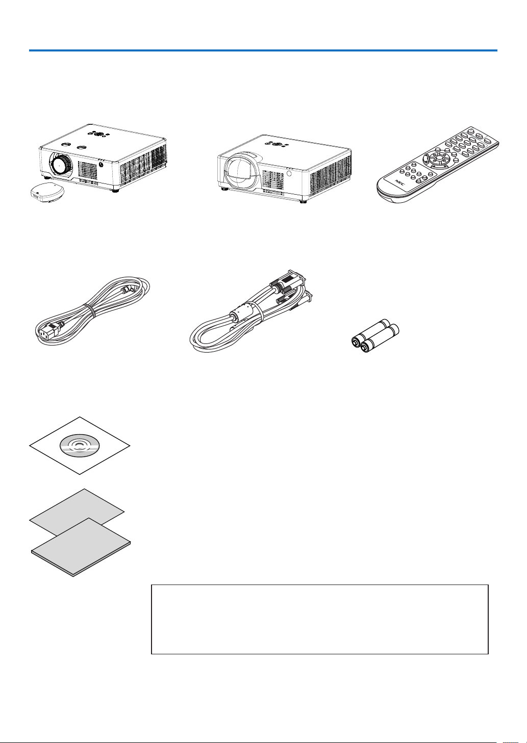
❶ What’s in the Box?
Make sure your box contains everything listed. If any pieces are missing, contact your dealer.
Please save the original box and packing materials if you ever need to ship your projector.
Projector
[PE506UL/PE506WL]
Lens cap × 1
(440165301)
(Only for PE506UL )
Power cord
(US: 310004900)
(EU: 310003100)
[PE456USL/PE456WSL] Remote control
Computer cable (VGA)
(310002200)
NEC Projector CD-ROM
User’s manual (PDF) (510054502)
• Important Information (510054602)
(393004710)
Batteries (AAA × 2)
(391003200)
[PE506UL/PE506WL]
• Quick Setup Guide
(For North America: 510054802)
(For Other countries than North
America: 510054701 and 510054802)
For North America only
Limited warranty
For customers in Europe:
You will find our current valid Guarantee Policy on our Web Site:
https://www.sharpnecdisplays.eu
[PE456USL/PE456WSL]
• Quick Setup Guide
(For North America: 510066100)
(For Other countries than North
America: 510066200 and 510066100)
1
Page 20

1. Introduction
❷ Introduction to the Projector
This section introduces you to your new projector and describes the features and controls.
• Support High Resolution Signal
The projector has the Multi-scan system to conform to many output signals. Up to WUXGA (COMPUTER),
4K@30Hz (HDMI).
• Useful Functions for Presentations
The digital zoom function allows you to focus on the crucial information during a presentation.
• Light source • Brightness
• A long-life laser diode is equipped in the light module.
The product can be operated at low cost because the laser light source can be used for a long time without
replacement or maintenance.
• Brightness can be adjusted
Unlike with ordinary light source, the brightness can be adjusted from 50 to 100% when Normal mode.
• Multi-language Menu Display
The screen menu of the projector is available in 27 languages: English, German, French, Italian, Spanish, Pol-
ish, Swedish, Dutch, Portuguese, Japanese, Simplified Chinese, Traditional Chinese, Korean, Russian,Arabic,
Turkish, Finnish, Norwegian, Danish, Indonesian, Hungarian, Czech, Kazakh, Vietnamese, Thai, Farsi, Romania.
• Convenient Maintenance Functions
Filter maintenance functions provide for better and proper maintenance of the projector.
• Security Function
The Security function helps you to ensure security of the projector. With the Key lock function, you can lock
the operation on the control panel. PIN code lock function prevents unauthorized use of the projector.
• Color board Function
At the time of simple projection on the colored wall, you can get the close color image to the color image pro-
jected on a white screen by selecting the similar color to the wall color from the preset four colors.
• Energy-saving
The Power management function reduces power consumption and maintains the light source life.
• Lot6, Lot26 supported with energy saving technology.
Select [Standby mode] supports Lot6, Select [Network Standby] supports Lot26.
• [ECO MODE] for low power consumption and [CARBON METER] display.
The projector has ECO MODE to refrain power consumption. Furthermore, the power-saving effect when the
[ECO MODE] is set is converted into the amount of reductions of CO2 emissions and this is indicated on the
confirmation message displayed on-screen menu [CARBON METER].
• Network
• CRESTRON ROOMVIEW compatibility
• Support the “MultiPresenter” Function.
About this user’s manual
The fastest way to get started is to take your time and do everything right the first time. Take a few minutes now to
review the user’s manual. This may save you time later on. At the beginning of each section of the manual you’ll find
an overview. If the section doesn’t apply, you can skip it.
2
Page 21
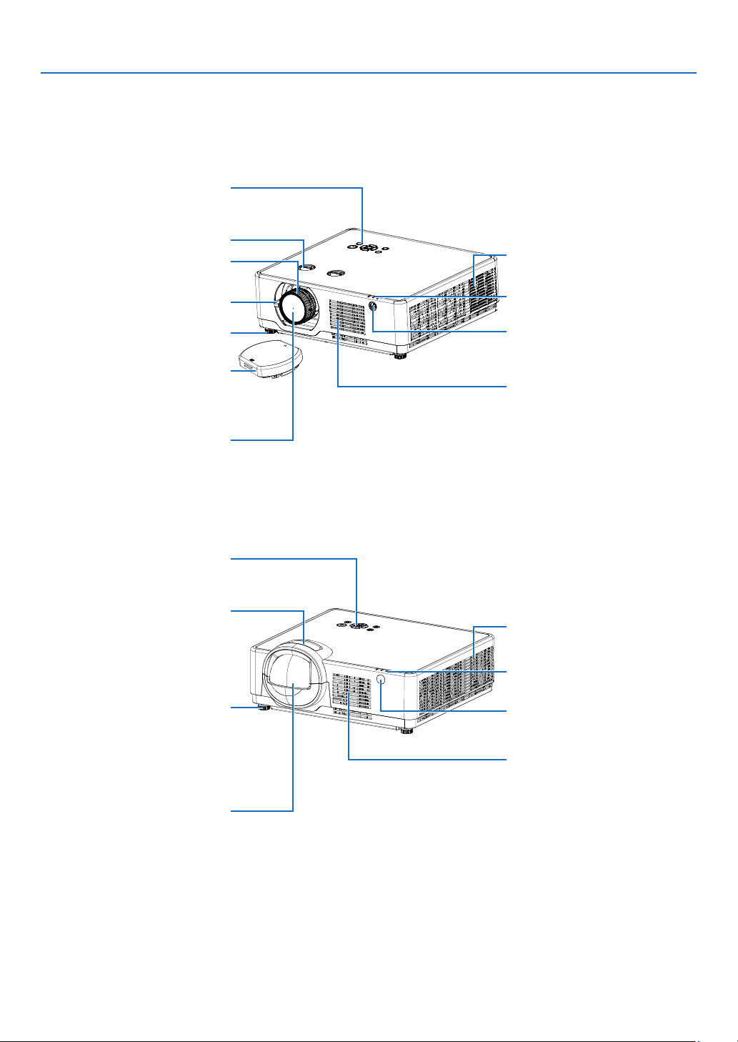
❸ Part Names of the Projector
Front/Top
[PE506UL/PE506WL]
Controls
(→ page 5)
Lens shift dial (→ page 19)
Focus Ring
(→ page 18)
Zoom Lever
(→ page 18)
Adjustable Tilt Foot
(→ page 17)
Lens Cap
(For PE506UL only)
For protecting lens.
Make sure to take it off during
projection.
Lens
1. Introduction
Exhaust Vent
Heated air is exhausted from here.
Indicators
(→ page 5)
Front Remote Sensor
(→ page 8)
Intake Vent
[PE456USL/PE456WSL]
(→ page 5)
Focus Ring
(→ page 18)
Adjustable Tilt Foot
(→ page 17)
Controls
Exhaust Vent
Heated air is exhausted from here.
Indicators
(→ page 5)
Front Remote Sensor
(→ page 8)
Intake Vent
Lens
3
Page 22
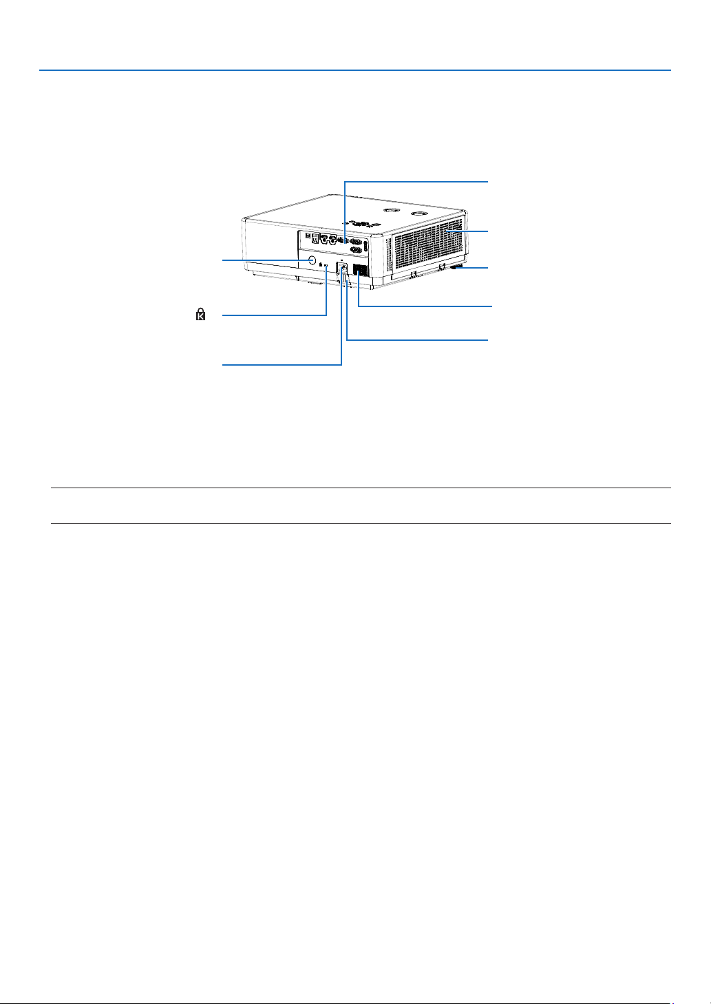
Rear
Rear Remote Sensor
(→ page 8)
Built-in Security Slot ( )*
Use for the theft prevention measure.
AC Input
Connect the supplied power cord’s
three-pin plug here, and plug the
other end into an active wall outlet.
(→ page 11)
1. Introduction
Terminal Panel
(→ page 6)
Intake Vent / Filter Cover
(→ page 85)
Adjustable Tilt Foot
(→ page 17)
Monaural Speaker (16 W)
Security chain opening
Attach an anti-theft device.
The security chain opening accepts
security wires or chains up to
0.18 inch/4.6 mm in diameter.
* This security slot supports the Micro Saver ® Security System.
NOTE:
• Security and theft protection lock compatible with Kensington security cables/equipment. For products, visit Kensington’s website.
4
Page 23
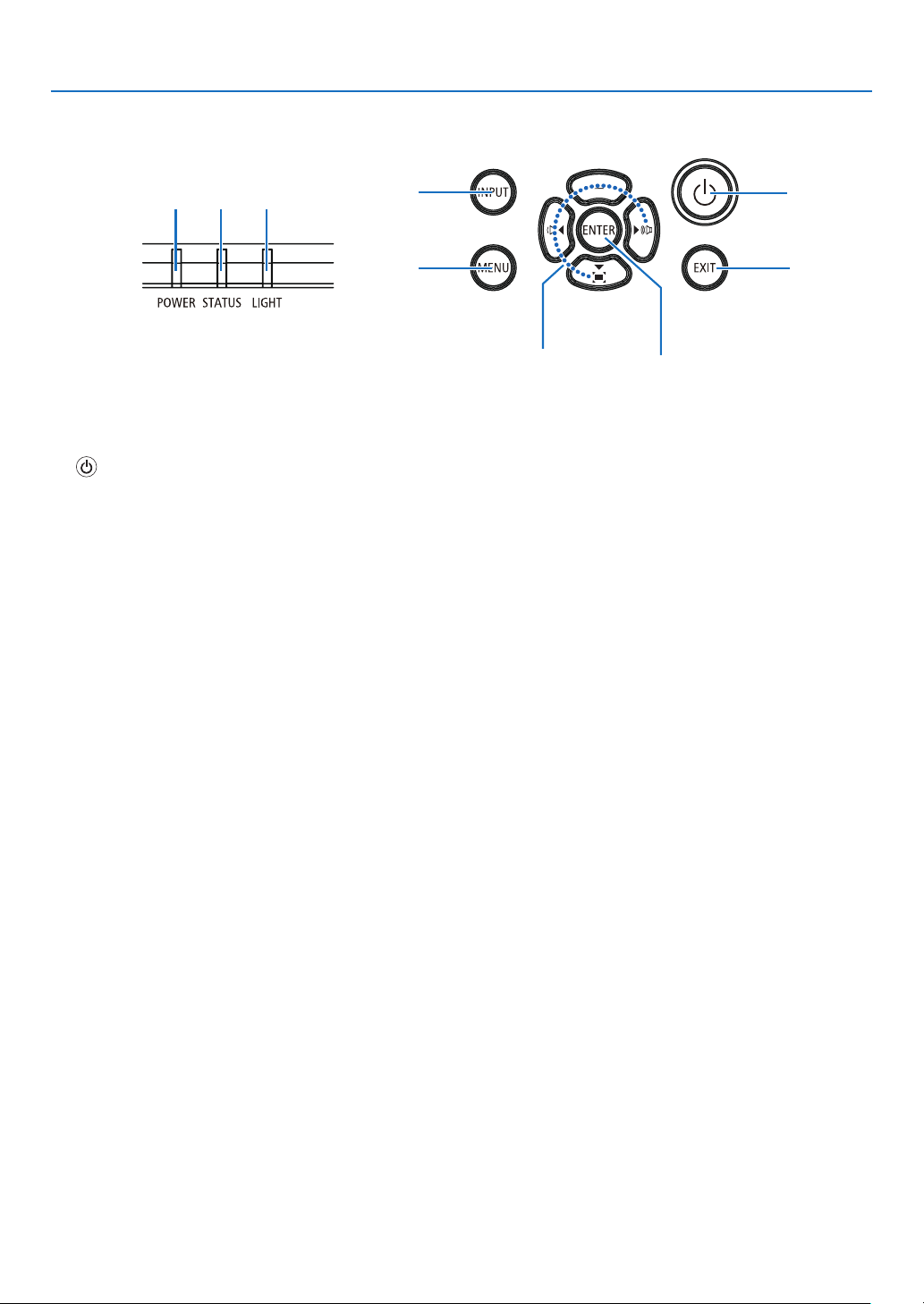
Top Features
1. Introduction
4 3 2
5
6
1. (POWER) Button
(→ page 12, 24)
2. LIGHT Indicator
(→ page 90 )
3. STATUS Indicator
(→ page 90)
4. POWER Indicator
(→ page 12, 24, 25, 90)
5. INPUT Button
(→ page 14)
6. MENU Button
(→ page 30)
7. EXIT Button
8. ▲▼◀▶ / Volume Buttons ◀▶ / Keystone Button ▼
(→ page 21, 23)
9. ENTER Button
8
1
7
9
5
Page 24
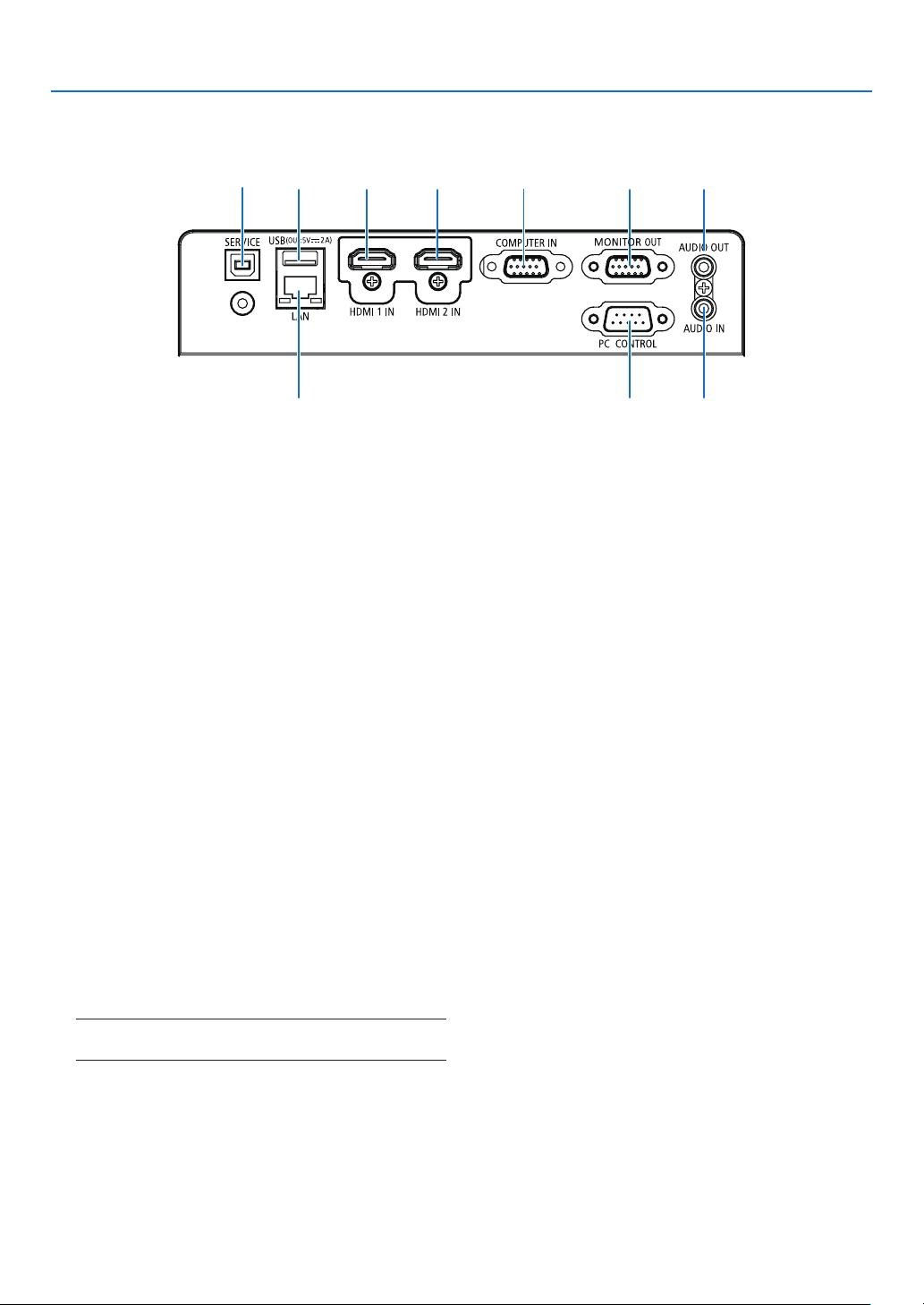
Terminal Panel Features
1. Introduction
14
2
5 6 7
3
1. SERVICE Port (USB Type B)
(for service purpose only)
2. USB Port (Type A)
For USB memory
(→ page 28)
3. LAN Port (RJ-45)
(→ page 80)
4. HDMI 1 IN Terminal (Type A)
(→ page 75, 76, 79)
5. HDMI 2 IN Terminal (Type A)
(→ page 75, 76, 79)
6. COMPUTER IN/ Component Input Terminal
(Mini D-Sub 15 Pin)
(→ page 11, 75, 78)
7. MONITOR OUT Terminal (Mini D-Sub 15 Pin)
(→ page 77)
8. PC CONTROL Port (D-Sub 9 Pin)
(→ page 100)
Use this port to connect a PC or control system.
This enables you to control the projector using serial
communication protocol. If you are writing your own
program, typical PC control codes are on page 100.
9. AUDIO OUT Mini Jack (Stereo Mini)
(→ page 77)
NOTE: The AUDIO OUT mini jack does not support earphone/
headphone terminal.
10. AUDIO IN Mini Jack (Stereo Mini)
(→ page 78)
8
9
10
6
Page 25
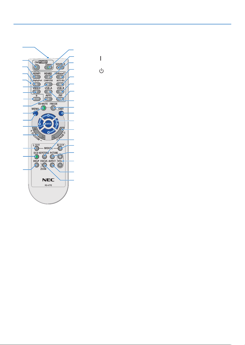
❹ Part Names of the Remote Control
1
17
31
32
33
21
22
27
29
30
26
12
18
10
13
1. Introduction
1. Infrared Transmitter
3
(→ page 8)
4
2
5
8
16
9
11
15
14
19
20
23
24
25
28
34
2. ( ) POWER ON Button
6
(→ page 12)
7
3. ( )POWER STANDBY
Button
(→ page 24)
4. SOURCE Button
(→ page 14)
5. HDMI 1 Button
(→ page 14)
6. HDMI 2 Button
(→ page 14)
7. HDBaseT Button
(This button does not work on this
series of projectors)
8. DisplayPort Button
(This button does not work on this
series of projectors)
9. COMPUTER Button
(→ page 14)
10. AUTO ADJ. Button
(→ page 23)
11. VIDEO Button
(This button does not work on this
series of projectors)
12. USB-A Button
(→ page 14, 28)
13. USB-B Button
(This button does not work on this
series of projectors)
14. APPS Button
(→ page 14, 83)
15. ID SET Button
(→ page 56)
16. Numeric Keypad Button/
CLEAR Button
(→ page 56)
17. PIP Button
(PIP button does not work on this
series of projectors)
18. FREEZE Button
(→ page 26)
19. AV-MUTE Button
(→ page 26)
20. MENU Button
(→ page 30)
21. EXIT Button
22. ▲▼◀▶ Button
23. ENTER Button
24. D-ZOOM (+)(–) Button
(→ page 26, 27)
25. MOUSE L-CLICK Button*
(This button does not work on this
series of projectors)
26. MOUSE R-CLICK Button*
(This button does not work on this
series of projectors)
27. PAGE ▽/△ Button
(This button does not work on this
series of projectors)
28. ECO Button
(→ page 45)
29. KEYSTONE Button
(→ page 21, 49)
30. PICTURE Button
(→ page 39)
31. VOL. (+)(–) Button
(→ page 23)
32. ASPECT Button
(→ page 36)
33. FOCUS/ZOOM Button
(This button does not work on this
series of projectors)
34. HELP Button
(→ page 60)
7
Page 26
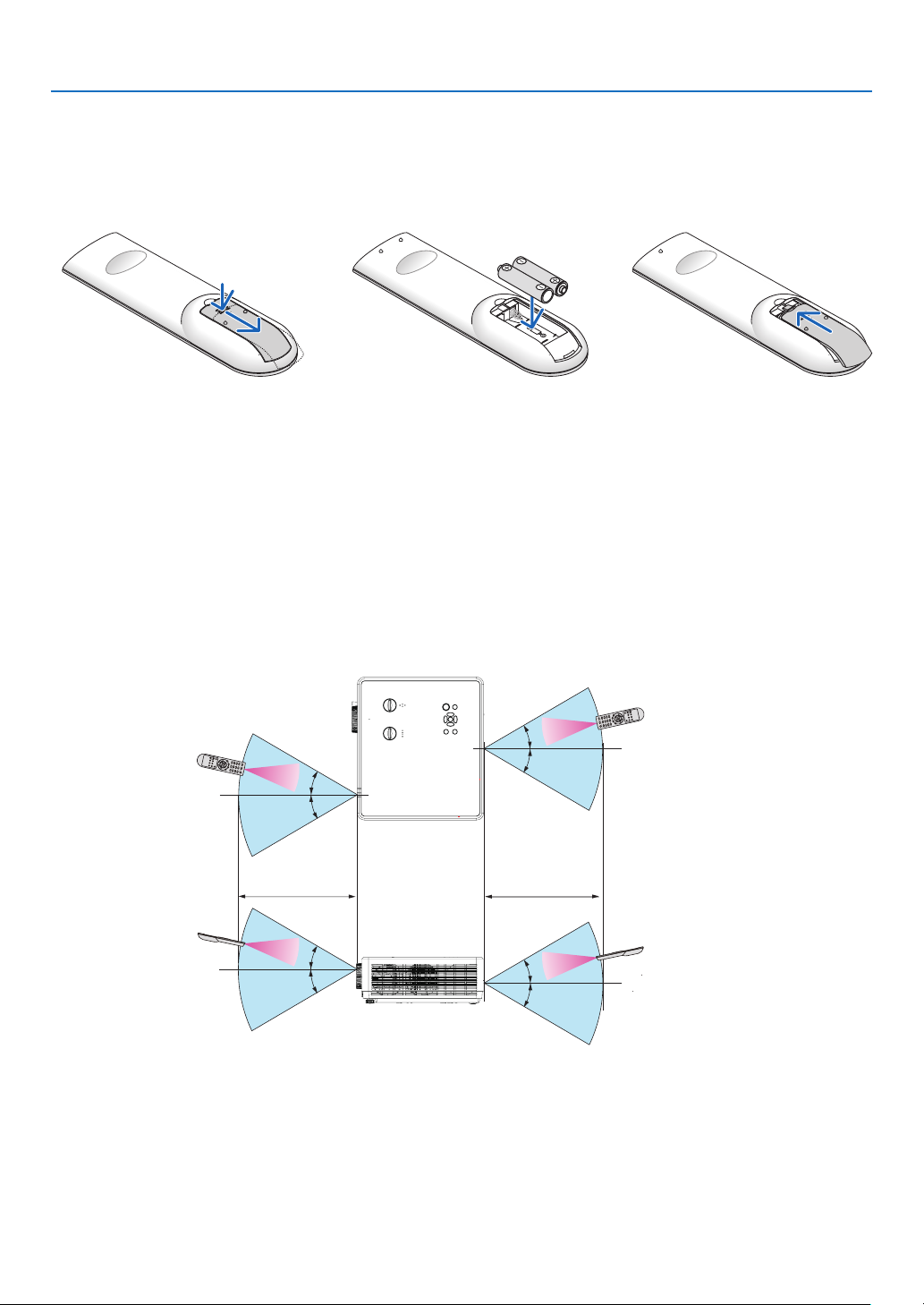
Battery Installation
1. Press firmly and slide the battery cover off.
2. Install new batteries (AAA).
Ensure that you have the batteries’ polarity (+/−) aligned
correctly.
1. Introduction
3. Slip the cover back over the
batteries until it snaps into
place. Do not mix different
types of batteries or new and
old batteries.
OPEN
Remote Control Precautions
• Handle the remote control carefully.
• If the remote control gets wet, wipe it dry immediately.
• Avoid excessive heat and humidity.
• Do not short, heat, or take apart batteries.
• Do not throw batteries into fire.
• If you will not be using the remote control for a long time, remove the batteries.
• Ensure that you have the batteries’ polarity (+/−) aligned correctly.
• Do not use new and old batteries together, or use different types of batteries together.
• Dispose of used batteries according to your local regulations.
Operating Range for Wireless Remote Control
30°
30°
30°
30°
Remote control
OPEN
22 feet/7 m22 feet/7 m
30°
30°
30°
30°
• The infrared signal operates by line-of-sight up to a distance of about 22 feet/7 m and within a 30-degree angle
of the remote sensor on the projector cabinet.
• The projector will not respond if there are objects between the remote control and the sensor, or if strong light
falls on the sensor. Weak batteries will also prevent the remote control from properly operating the projector.
8
Page 27
1. Introduction
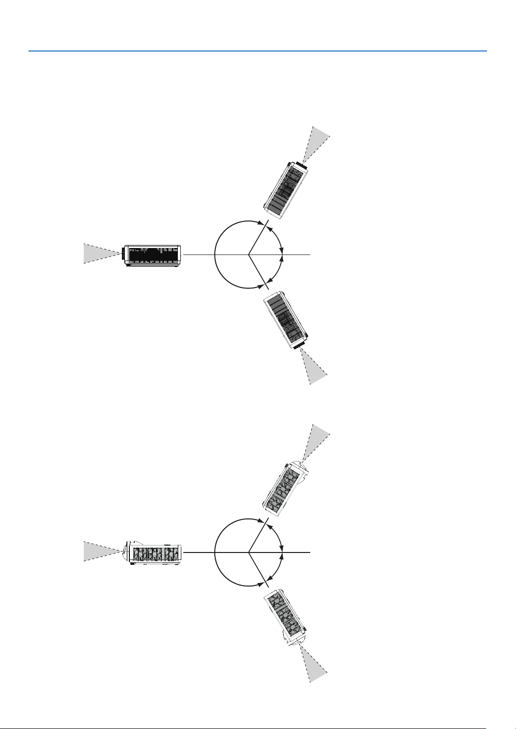
Angle sensor
The installation angle range that the built-in angle sensor of the projector can detect is shown in the figure
below.
[PE506UL/PE506WL]]
When selecting [Auto ceiling /
Front] or [Auto ceiling / Rear] as
projection way, the projector will
be judged as the front projection
automatically .
[PE456USL/PE456WSL]
120°
120°
When selecting [Auto ceiling /
Front] or [Auto ceiling / Rear] as
projection way, the projector will
be judged as the front projection
automatically .
When selecting [Auto ceiling /
Front] or [Auto ceiling / Rear] as
projection way, the projector will
be judged as the front projection
automatically .
60°
60°
When selecting [Auto ceiling /
Front] or [Auto ceiling / Rear] as
projection way, the projextor will
be judged as the ceiling projection
automatically .
120°
120°
When selecting [Auto ceiling /
Front] or [Auto ceiling / Rear] as
projection way, the projector will
be judged as the front projection
automatically .
60°
60°
When selecting [Auto ceiling /
Front] or [Auto ceiling / Rear] as
projection way, the projextor will
be judged as the ceiling projection
automatically .
9
Page 28

2. Projecting an Image (Basic Operation)
This section describes how to turn on the projector and to project a picture onto the screen.
❶ Flow of Projecting an Image
Step 1
• Connecting your computer / Connecting the power cord (→ page 11)
Step 2
• Turning on the projector (→ page 12)
• Change the On-Screen menu language (→ page 13)
Step 3
• Selecting a source (→ page 14)
Step 4
• Adjusting the picture size and position (→ page 15)
• Correcting keystone distortion [KEYSTONE] (→ page 21)
Step 5
• Adjusting a picture and sound
- Optimizing a computer signal automatically (→ page 23)
- Turning up or down volume (→ page 23)
Step 6
• Making a presentation
Step 7
• Turning off the projector (→ page 24)
Step 8
• When Moving the Projector (→ page 25)
10
Page 29
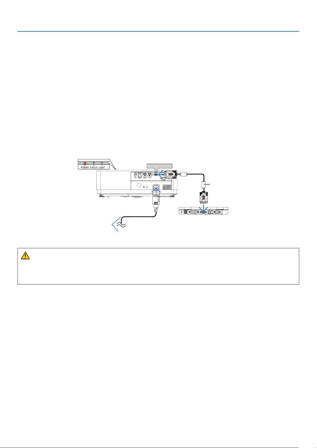
2. Projecting an Image (Basic Operation)
❷ Connecting Your Computer/Connecting the Power Cord
1. Connect your computer to the projector.
This section will show you a basic connection to a computer. For information about other connections, see
"7. Installation and Connections" on page 75.
Connect the computer cable (VGA) between the projector’s COMPUTER IN terminal and the computer’s port (mini
D-Sub 15 Pin). Turn two thumb screws of both terminals to fix the computer cable (VGA).
2. Connect the supplied power cord to the projector.
First connect the supplied power cord’s three-pin plug to the AC IN terminal of the projector, and then connect
another plug of the supplied power cord directly in the wall outlet. Do not use any plug converter.
The projector’s power indicator will start blinking orange.
* This will apply for both indicators when [NORMAL] is selected for [STANDBY MODE]. See the Power Indicator
section. (→ page 91)
COMPUTER IN
Computer cable (VGA)
(supplied)
Make sure that the
prongs are fully inserted
into both the AC IN and
the wall outlet.
→ To wall outlet
CAUTION:
Parts of the projector may become temporarily heated if the projector is turned off with the POWER button or if
the AC power supply is disconnected during normal projector operation.
Be careful to handle the projector.
11
Page 30
❸ Turning on the Projector
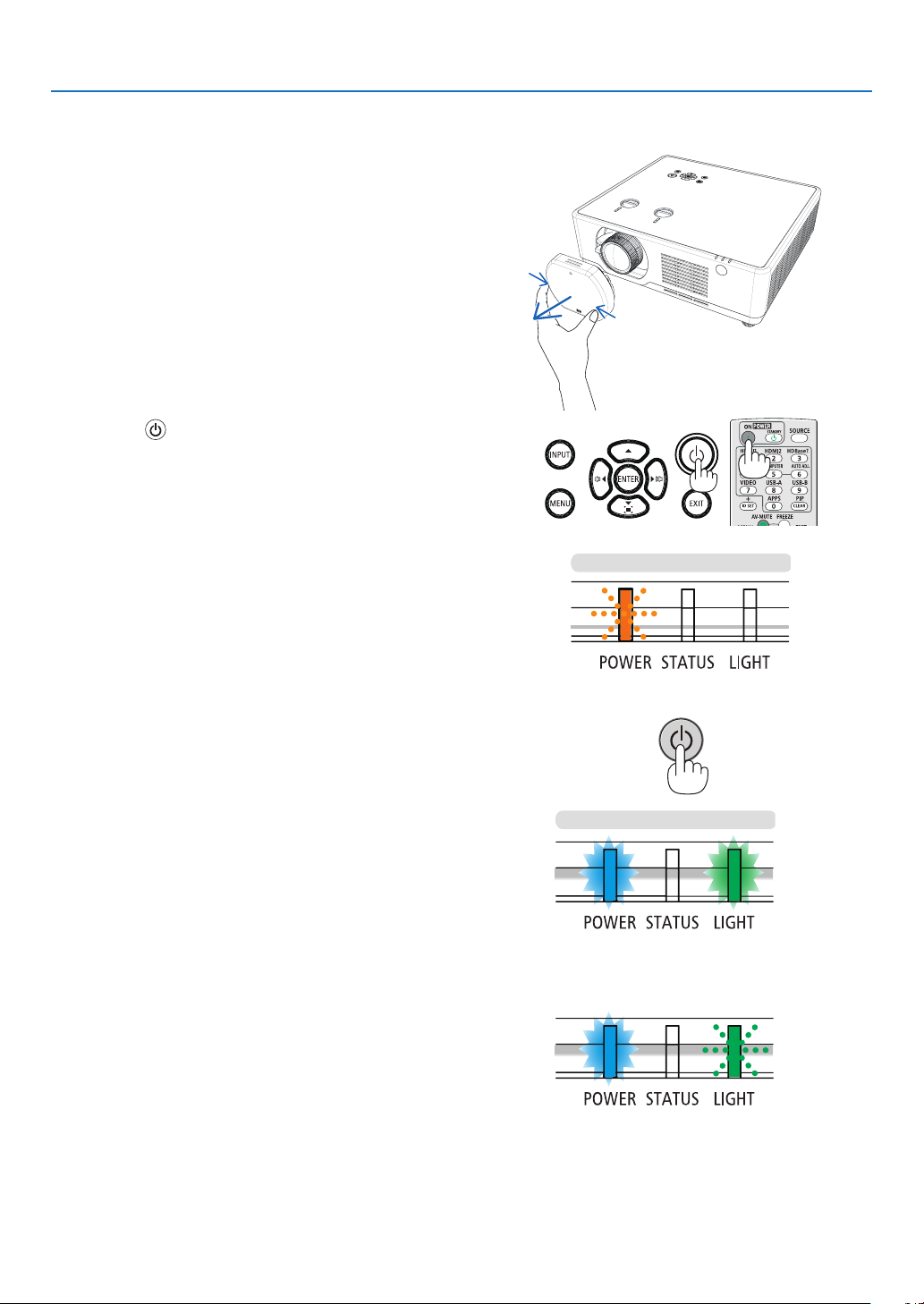
1. Remove the lens cap.
(For PE506UL only )
Press and hold both ends of the lens cap and pull it toward
you.
2. Press the (POWER) button on the projector cabinet
or the POWER ON button on the remote control.
The POWER indicator will blink and the projector will
become ready to use.
TIP:
• When the message “PIN code” is displayed, it means that the
[SECURITY] feature is turned on.
(→ page 52)
2. Projecting an Image (Basic Operation)
Standby
After you turn on your projector, ensure that the computer
or video source is turned on.
Blanking orange light
Power On
Steady blue light
or
Steady blue light
(→ page 91)
Steady green light
Blanking green light
12
Page 31
2. Projecting an Image (Basic Operation)
❹
Change the On-Screen menu
language
Selecting the On-Screen
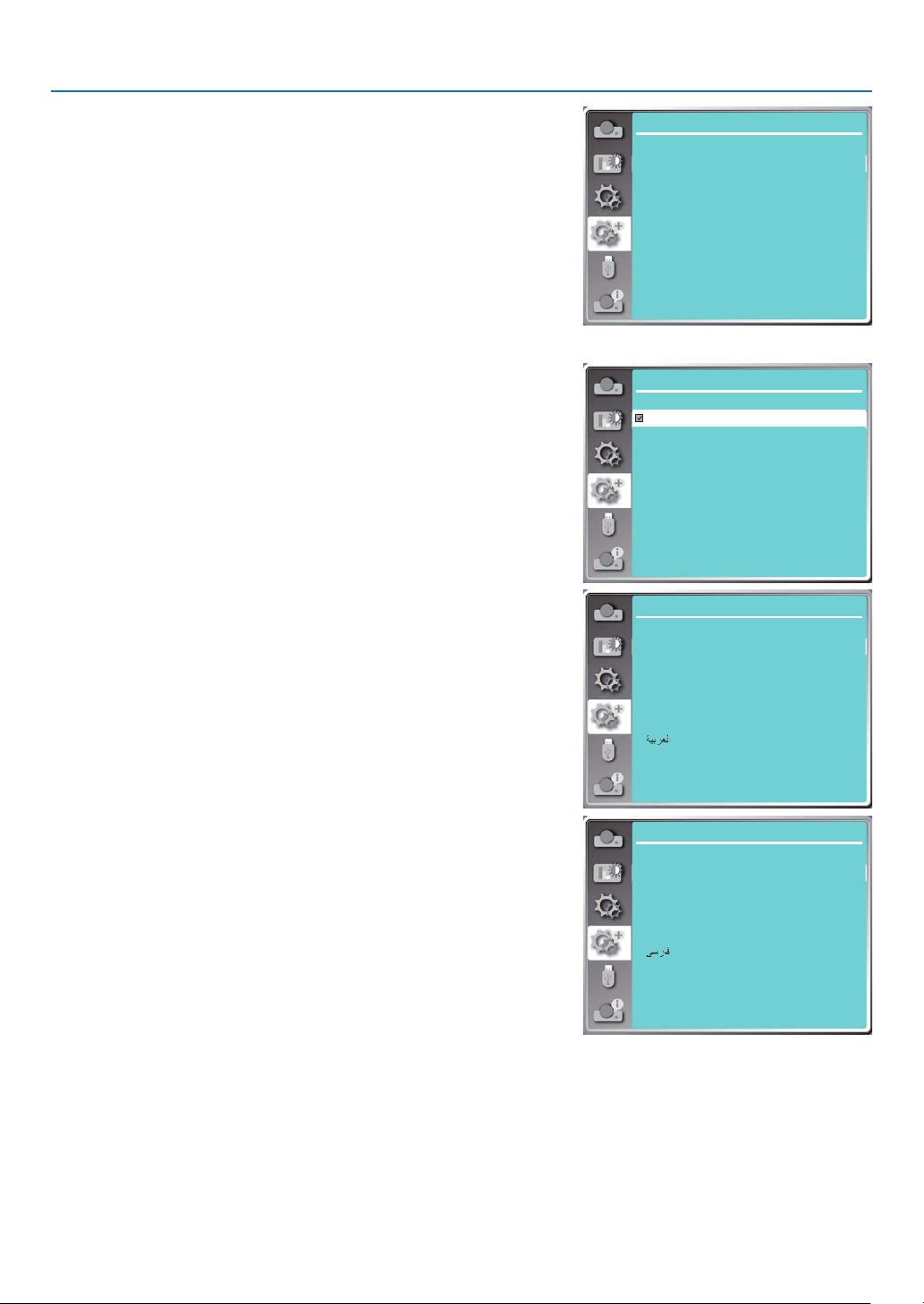
1. Press the MENU button on the remote control or on the top control
panel to display the On-Screen menu.
2. Press ▲ ▼ button to select the Expand menu, then press the EN-
TER or ▶ button to select the Language option.
3. Then press ▲ ▼ button to select the required language.
(→ page 47)
Expand
Language
Auto setup
Keystone
Security
Power management
Filter
Test pattern
Network setup
Control ID
Factory default
Expand
Language 1/3
English
Deutsch
Français
Italiano
Español
Português
Nederlands
Svenska
Suomi
Norsk
Expand
Language 2/3
Dansk
Polski
český
Magyar
Русский
Türkçe
13
Қазақ
Tiếng Việt
한글
Expand
Language 3/3
日本語
ภาษาไทย
中文繁体
中文
Bahasa Indonesia
Română
Page 32
2. Projecting an Image (Basic Operation)
5 Selecting a Source
Selecting the computer source
NOTE: Turn on the computer source equipment connected to the projector.
Detecting the Signal Automatically
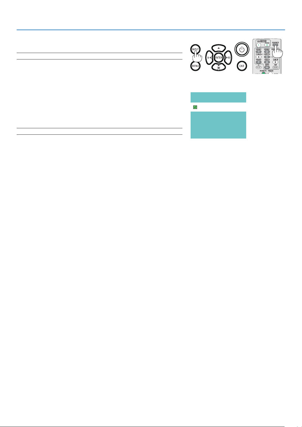
Press the INPUT button. The projector will search for the available input
source and display it. The input source will change as follows:
Computer →HDMI1 → HDMI2 → USB-A → LAN
• With the INPUT screen displayed, you can press the ▼▼ button to
select the input source.
TIP: If no input signal is present, the input will be skipped.
Using the Remote Control
Press any one of the Computer, HDMI1, HDMI2, USB-A, or APPS buttons.
Computer
HDMI 1
HDMI 2
USB-A
LAN
14
Page 33
2. Projecting an Image (Basic Operation)
A B C
A B C
A B C
6 Adjusting the Picture Size and Position
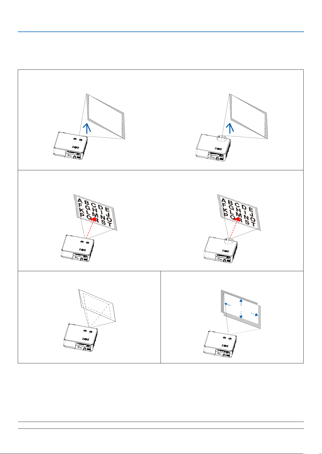
Use the adjustable tilt foot, the zoom function or the focus ring to adjust the picture size and position.
In this chapter drawings and cables are omitted for clarity.
Adjusting the throw angle (the height of an image) [Tilt foot] (→ page 17)
[PE506UL/PE506WL]
Adjusting the focus [Focus ring] (→ page 18)
[PE506UL/PE506WL]
[PE456USL/PE456WSL]
[PE456USL/PE456WSL]
Finely adjusting the size of an image
[Zoom lever] (→ page 18)
Adjusting the projected image’s vertical and
horizontal position [Lens shift](→ page 19)
A B C
NOTE: [Zoom lever] and [Lens shift] functions are only available for PE506UL /PE506WL.
15
A B C
Page 34
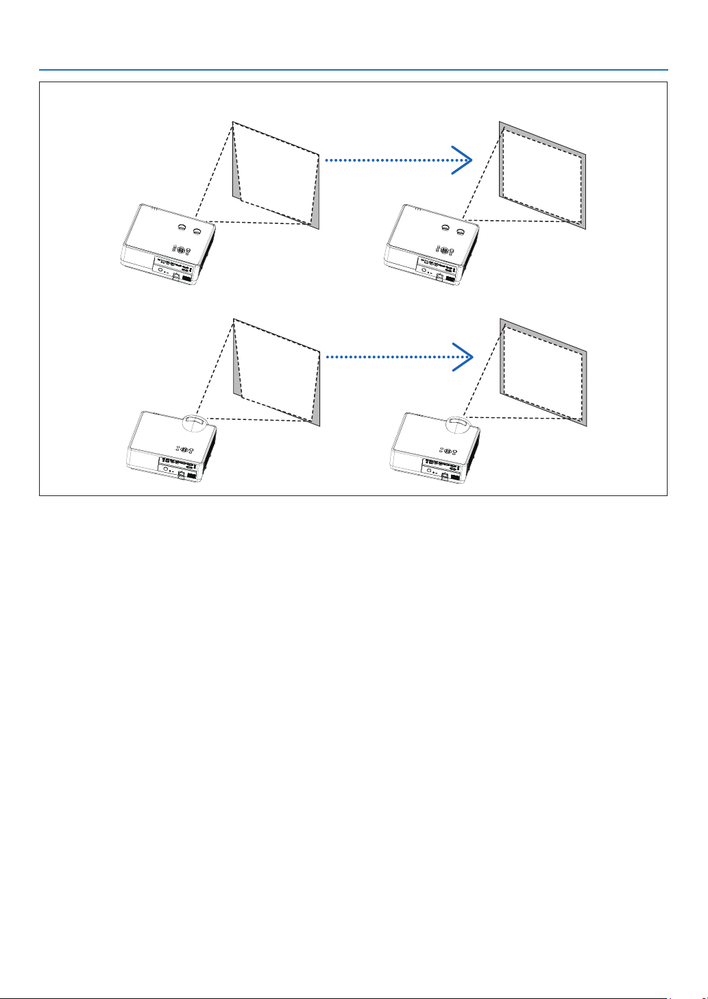
Adjusting the keystone correction [KEYSTONE]* (→ page 21)
[PE506UL/PE506WL]
[PE456USL/PE456WSL]
2. Projecting an Image (Basic Operation)
Automatic Keystone Correction function is turned off at the time of shipment.
To perform keystone correction manually, see “❻ Correcting Keystone Distortion [KEYSTONE]” on page 21.
16
Page 35
2. Projecting an Image (Basic Operation)
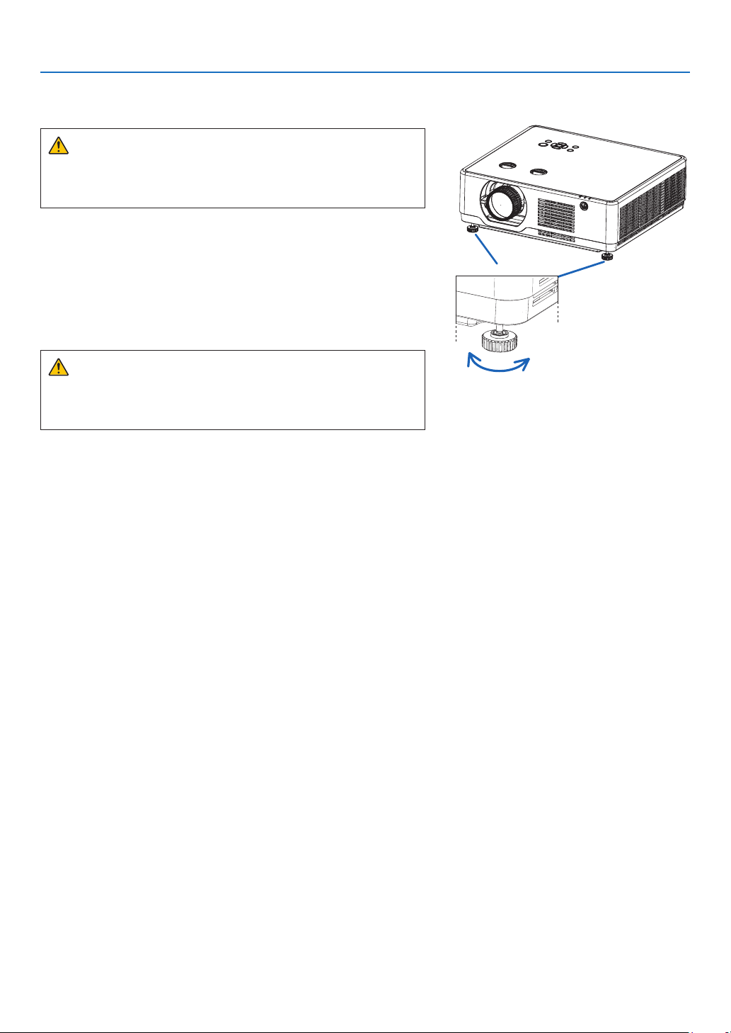
Adjust the Tilt Foot
1. Place the projector perpendicular to the screen..
CAUTION:
Do not try to touch the exhaust vent during tilt foot adjustment as
it can become heated while the projector is turned on and after it
is turned off.
2. Rotate the left and right adjustable tilt foot to make adjustments to the desired height.
• Rotate the tilt clockwise to raise the projector, and counterclock-
wise to lower the projector or retract the adjustable foot.
• The tilt foot can be extended up to 0.71 inch/18 mm.
• There is approximately 3.5 degrees (up) of adjustment for the
front of the projector.
CAUTION:
• Do not use the tilt-foot for purposes other than originally intended.
Misuses such as using the tilt foot to carry or hang (from the wall
or ceiling) the projector can cause damage to the projector.
Tilt foot
Up
Down
17
Page 36
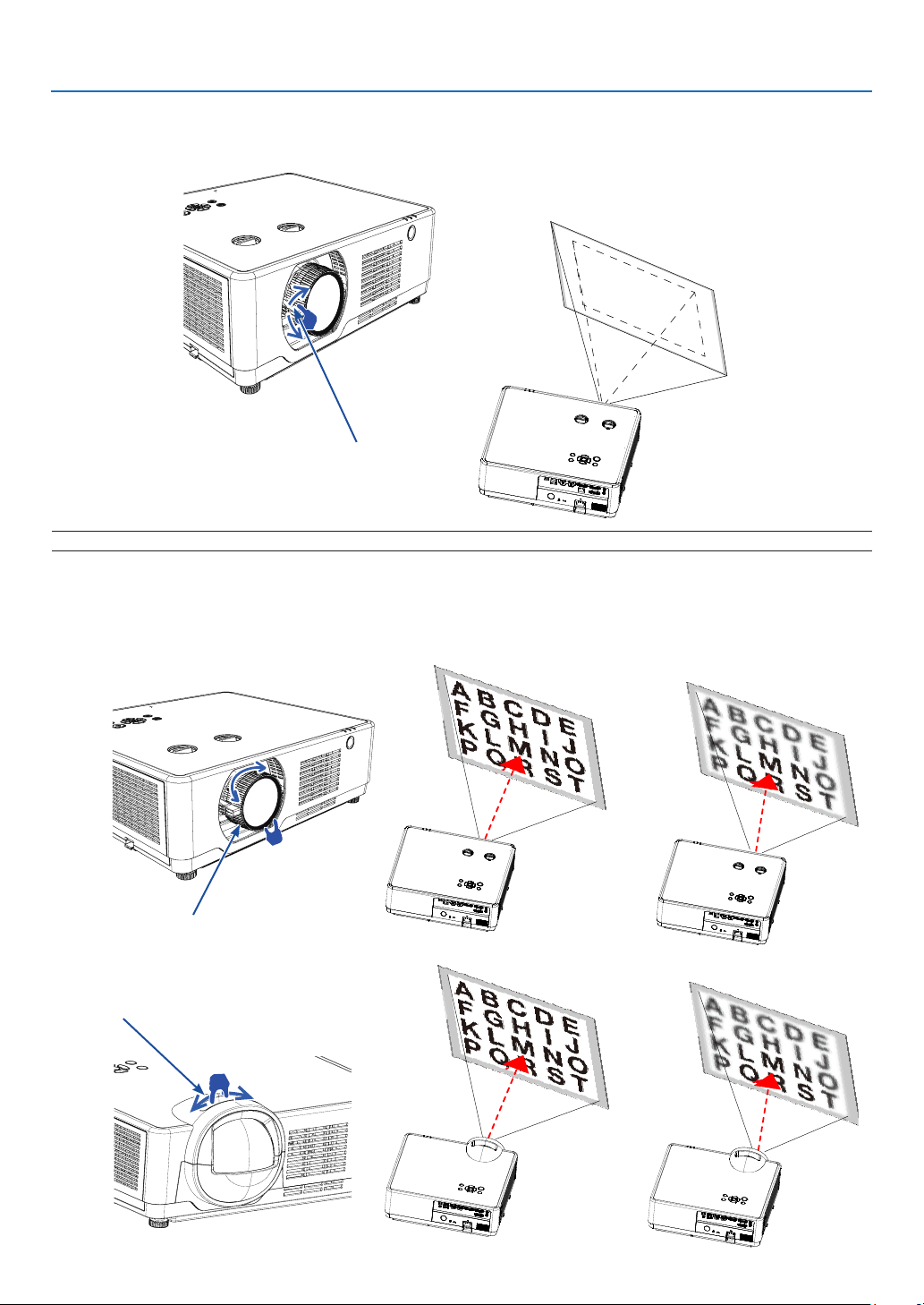
Zoom
A B C
A B C
Use the ZOOM lever to adjust the image size on the screen.
Zoom Lever
NOTE: [Zoom lever] functions are only available for PE506UL /PE506WL.
2. Projecting an Image (Basic Operation)
A B C
Focus
Use the FOCUS ring to obtain the best focus.
[PE506UL/PE506WL]
Focus Ring
[PE456USL/PE456WSL]
Focus Ring
18
Page 37
Lens shift
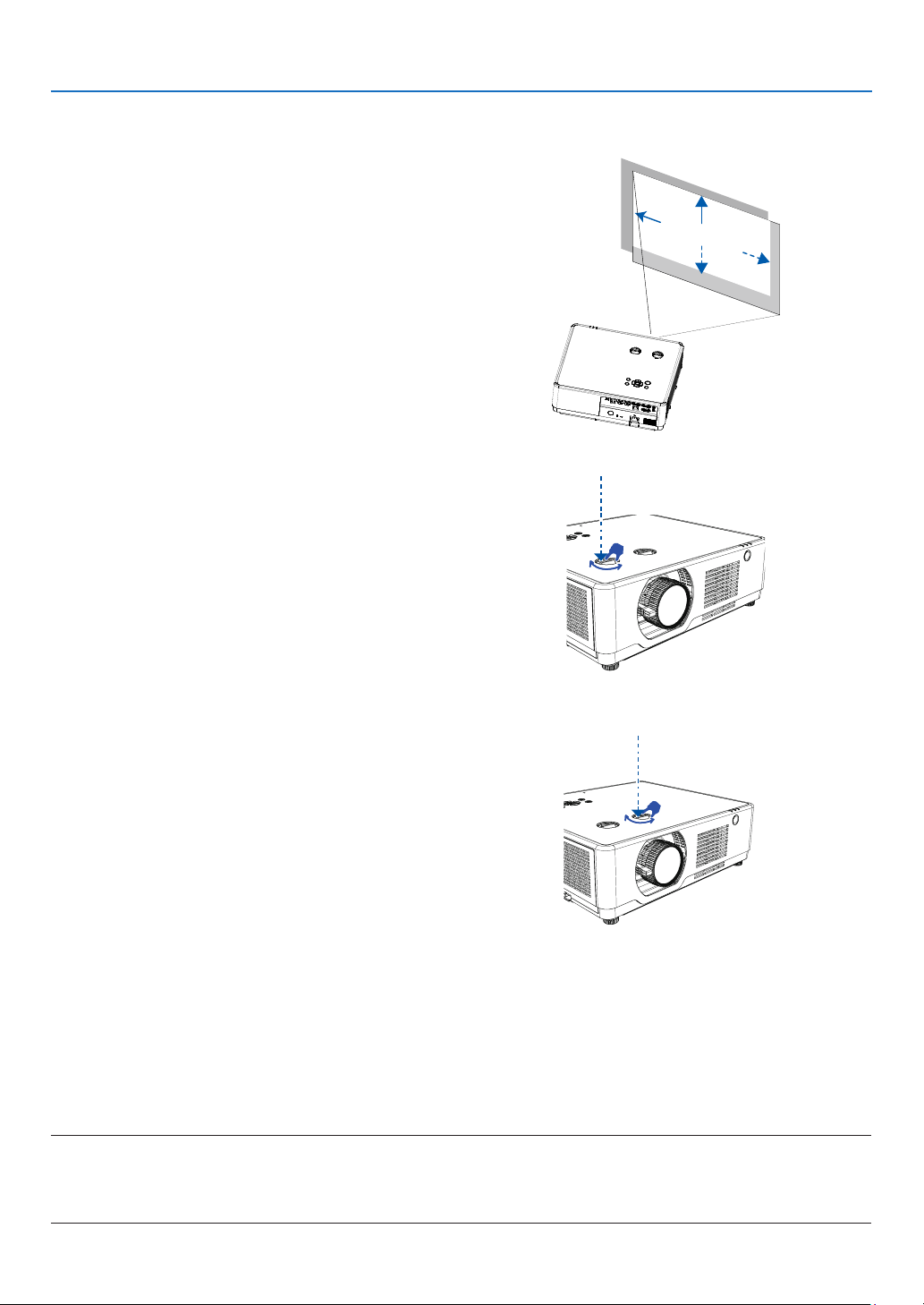
Press the ① and ② dial to make Lens shift adjustment
manually.
2. Projecting an Image (Basic Operation)
A B C
Rotate ① dial , then you can move upward and downward
the image with a distance up to +55% (PE506WL) and
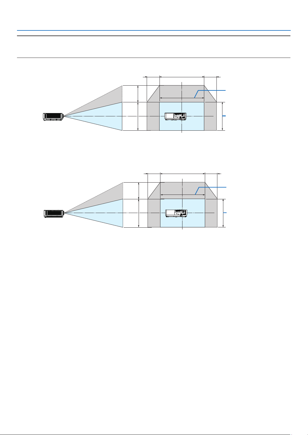
60% (PE506UL) between the upper and lower range of
the image.
Rotate ② dial, then you can move rightward and leftward
the image with a distance up to -26% ~ +26% (PE506WL)
and -29% ~ +29% (PE506UL) of the width of the image.
①
Len shift V
②
Len shift H
NOTE:
• After turning the lens shift dial to align the projection position, turn the lens shift dial slightly to the opposite side to loosen it.
• If the lens shift dial is stopped at the aligned position, the lens shift position may drift due to vibrations or environmental temperature.
• [Lens shift] functions are only available for PE506UL /PE506WL.
19
Page 38
2. Projecting an Image (Basic Operation)
TIP:
• The diagram below shows the lens shift adjustment range ([ORIENTATION]: [DESKTOP FRONT]).
• For the lens shift adjustment range regarding the [CEILING FRONT] projection, see page 73-74.
[PE506UL]
29% H29% H 100% H
60% V
100% V
Width of projected
image
Height of projected
image
[PE506WL]
26% H26% H 100% H
55% V
100% V
Width of projected
image
Height of projected
image
Description of symbols: V indicates vertical (height of the projected image), H indicates horizontal (width of the
projected image).
20
Page 39

2. Projecting an Image (Basic Operation)
7 Correcting Keystone Distortion [KEYSTONE]
You may adjust keystone distortion of image in your projector with the H/V keystone adjustment. Follow steps below
to adjust keystone distortion of projected image manually.
Before performing KEYSTONE correction
Press the KEYSTONE button on your remote control. The keystone adjustment dialog box displays ( including H/V
keystone, 4-Corner correction, 6-Corner correction, Curved correction, Grid Image Tune, Reset), press ▲▼◀ ▶
button to adjust keystone distortion.
You may save your settings for keystone adjustment.
• H/V keystone......Adjust the projected image when the projector is on the horizontal or vertical keystone distortion.
• 4-Corner correction......Adjust the projected image when the projector is keystone distortion of four corners .
• 6-Corner correction......Adjust the projected image when the projector is keystone distortion of six corners.
• Curved correction......Adjust the projected image when the projector linearity is uneven or the projected images
bent vertically and horizontally.
• Grid image tune......Adjust the local points of the projected image.
• Reset......The correction values will be restored to the factory defaults.
H/V keystone
4-Corner correction
6-Corner correction
Curved correction
Grid image Tune
Reset value
1. Press the ▼ button on the projector cabinet.
The H/V keystone screen will be displayed on the
screen.
● Press the KEYSTONE button when using the remote
control.
2. Press the ▼ button to select H/V keystone, then
press the ENTER button to select the H keystone.
And press the button to make adjustment so
that the left and right sides of the projected image are
parallel.
● Adjust the horizontal keystone distortion.
Screen frame
Projected area
21
Page 40

2. Projecting an Image (Basic Operation)
3. Align the left (or right) side of the screen with the left
(or right) side of the projected image.
● Use the shorter side of the projected image as the
base.
● In the right example, use the left side as the base.
Align left side
4. Press the ▼ button to select V KEYSTONE and then
use the ▲▼ button so that the top and bottom sides
of the projected image are parallel.
● Adjust the vertical keystone distortion.
5. Repeat steps 2 and 4 to correct keystone distortion.
6. After completing Keystone correction, press the EXIT
button for some time to turn off the menu.
NOTE:
• The arrow mark looks white when there is no keystone adjustment in existence.
• The arrow mark indicating the adjustment direction turns red.
• The arrow mark disappears when the maximum H/V keystone adjustment limit reaches.
• The keystone prompt box will disappear if you press the keystone button again when it is displaying. Press the
ENTER button again to switch the six correction items.
• The adjustable range is subject to source of signal input.
• For further details about keystone function, please turn to page 49-52.
• When using the VIEWER, you cannot use the ▼ button on the panel to directly call up the keystone correction
menu.
To return the keystone adjustments to default:
1. The Keystone screen will be displayed on the screen.
2. Press ▼ button to select Reset.
3. Press the or the ENTER button.
● The adjustments will be reset.
NOTE:
All adjusted values set in the [KEYSTONE] adjustment are reset to initial values
22
Page 41
2. Projecting an Image (Basic Operation)
8 Optimizing Computer Signal Automatically
Adjusting the Image Using Auto Adjust
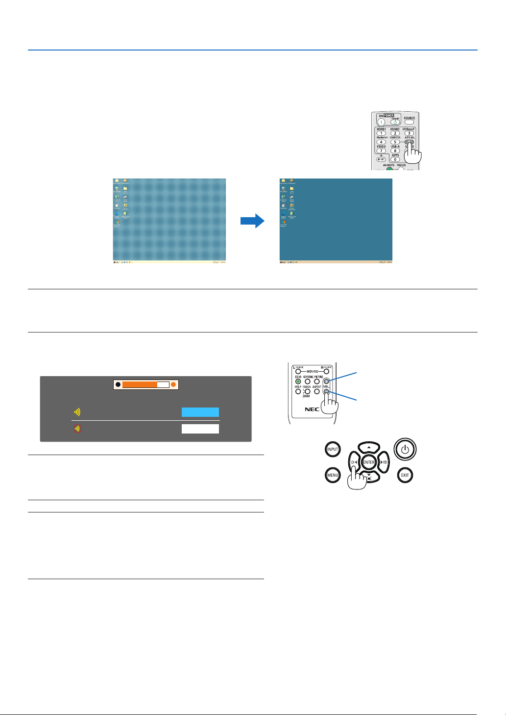
Optimizing a computer image automatically. (Auto PC adj.)
Press the AUTO ADJ. button to optimize a computer image automatically.
This adjustment may be necessary when you connect your computer
for the first time.
[Poor picture] [Adjusted picture]
NOTE:
• Some signals may take some time to display or may not be displayed correctly.
• If the Auto Adjust operation cannot optimize the computer signal, try to adjust [Fine sync], [H position], [V position], and [H. size] manually.
(→ page 35, 36)
9 Turning Up or Down Volume
Sound level from the speaker or audio output can be adjusted.
Volume
Mute
TIP: When no menus appear, the ◀ and ▶ buttons on the projector cabinet
work as a volume control.
When the above volume adjustment menu appears, press ▲ and ▼ buttons
to control the mute on and off.
NOTE:
• Volume control is available with the ◀ or ▶ button but invaild through
the remote control when an image is magnified by using the D-ZOOM
(+) button or when the menu is displayed.
• Volume control is not available with the ◀ or ▶ button when VIEWER
is used.
19
Off
Increase volume
Decrease volume
23
Page 42
❿ Turning off the Projector
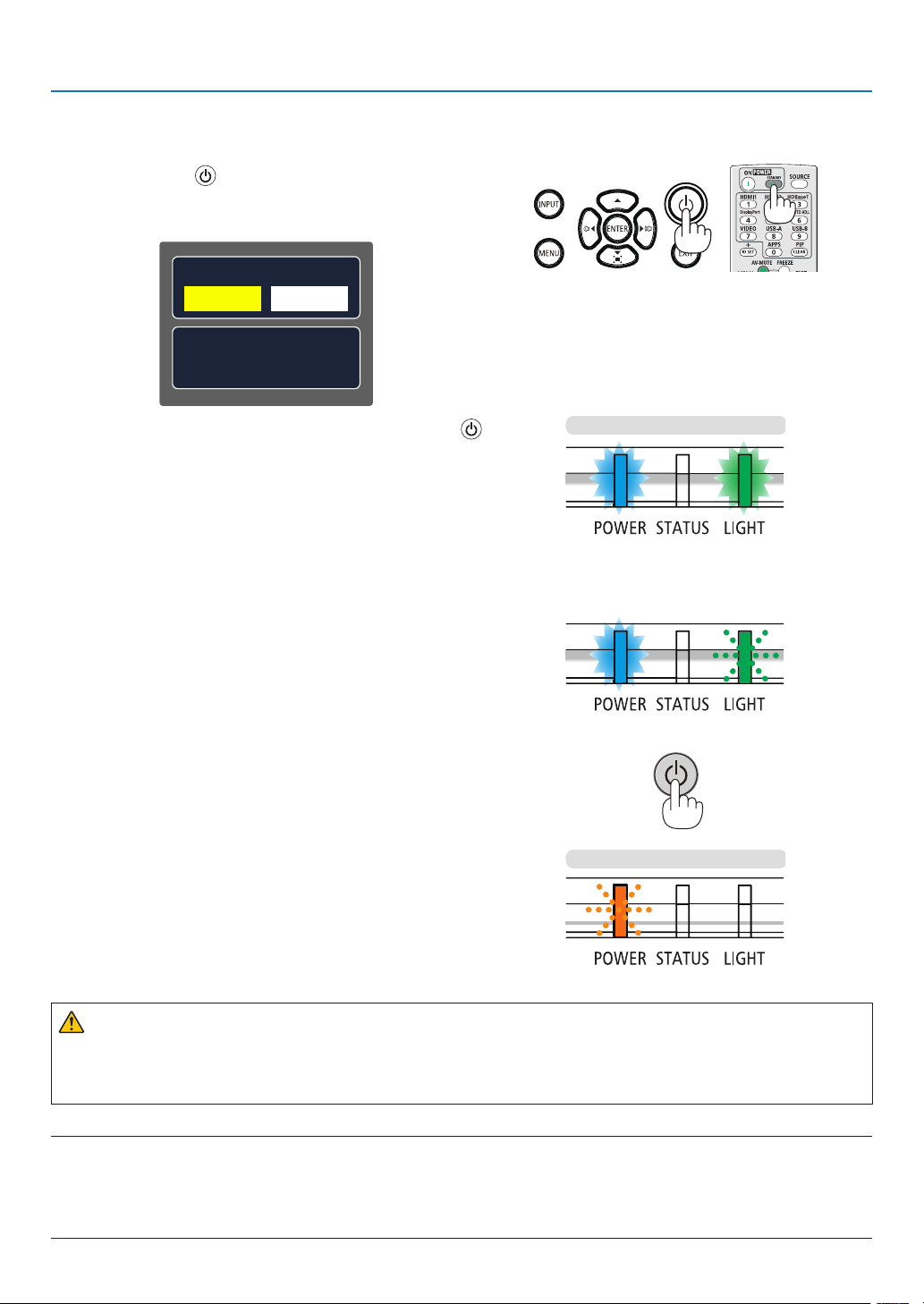
To turn off the projector:
1. First, press the (POWER) button on the projector
cabinet or the STANDBY button on the remote control.
The confirmation message will be displayed.
2. Projecting an Image (Basic Operation)
Power off?
Yes No
Carbon savings-session
[g-CO2]66.5200
2. Secondly, press the ENTER button or press the
(POWER) or the STANDBY button again.
The light source will turn off and the projector will go into
standby mode. When in standby mode, the POWER indicator will blinking orange and the STATUS and LIGHT indicator will turn off when [Normal] is selected for [STANDBY
MODE].
Power On
Steady blue light
Steady blue light
Steady green light
or
Blanking green light
Standby
Blanking orange light
CAUTION:
Parts of the projector may become temporarily heated if the projector is turned off with the POWER button or if
the AC power supply is disconnected during normal projector operation.
Use caution when picking up the projector.
NOTE:
• While the power indicator is blinking blue in short cycles, the power cannot be turned off.
• You cannot turn off the power for 60 seconds immediately after turning it on and displaying an image.
• Do not disconnect the AC power supply to the projector within 10 seconds after making adjustment or setting changes and closing the
menu. Doing so can cause loss of adjustments and settings.
24
Page 43

2. Projecting an Image (Basic Operation)
When Moving the Projector
Preparation: Make sure that the projector is turned off.
1. Put on the lens cap(For PE506UL only ).
2. Unplug the power cord.
3. Disconnect any other cables.
• Remove the USB memory or the USB Wireless LAN Unit if it is inserted into the projector.
(→ page 28,80)
25
Page 44
3. Convenient Features
❶ Turning off the Image and Sound
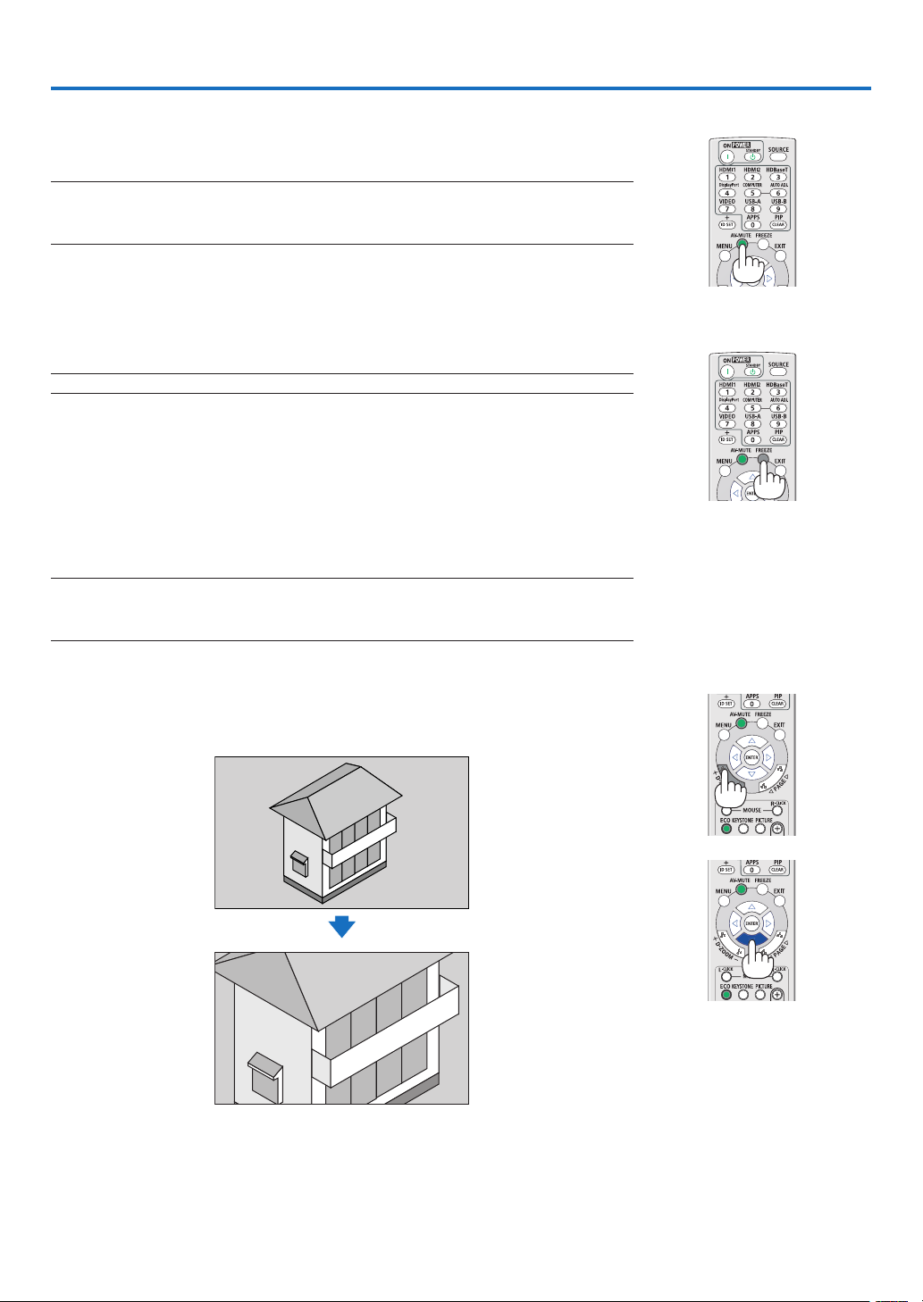
Press the AV-MUTE button to turn off the image and sound for a short period of
time. Press again to restore the image and sound.
NOTE:
• Even though the image is turned off, the menu still remains on the screen.
• Sound from the AUDIO OUT jack (Stereo mini) can be turned off.
❷ Freezing a Picture
Press the FREEZE button to freeze a picture. Press again to resume motion.
NOTE: The image is frozen but the original video is still playing back.
• This feature can not be used when LAN, and USB-A is selected as the input
terminal.
❸ Magnifying a Picture
You can enlarge the picture up to four times.
NOTE:
• The maximum magnification may be less than four times depending on the signal.
• This feature can not be used when LAN, and USB-A is selected as the input terminal.
To do so:
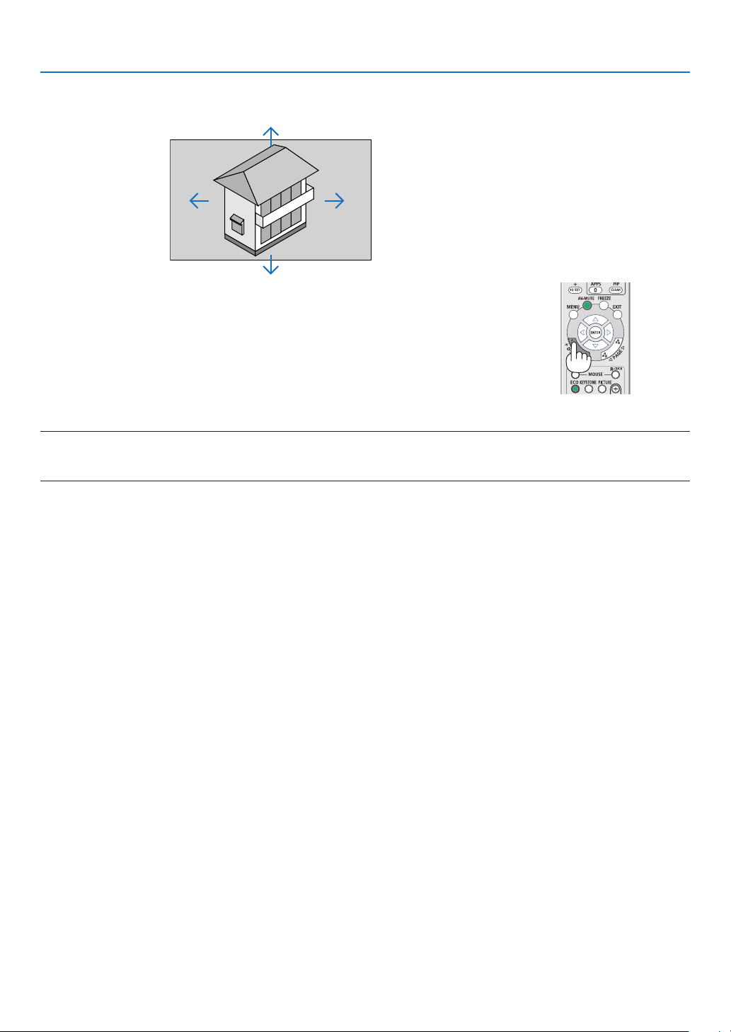
1. Press the D-ZOOM (+) button to magnify the picture.
To move the magnified image, use the ▲,▼,◀ or ▶ button.
26
Page 45
3. Convenient Features
2. Press the ▲▼◀▶ button.
The area of the magnified image will be moved.
3. Press the D-ZOOM (-) button to magnify the picture.
Each time the D-ZOOM (-) button is pressed, the image is reduced.
NOTE:
• The image will be magnified or demagnified at the center of the screen.
• Press the ASPECT button on the remote control or select the Aspect function on the Display menu can cancel the current magnification.
27
Page 46
4. Using the VIEWER
USB-A function
When the USB memory insert into the projector, the USB-A function can project pictures which is stored in the USB
memory.
The projected content of USB-A function
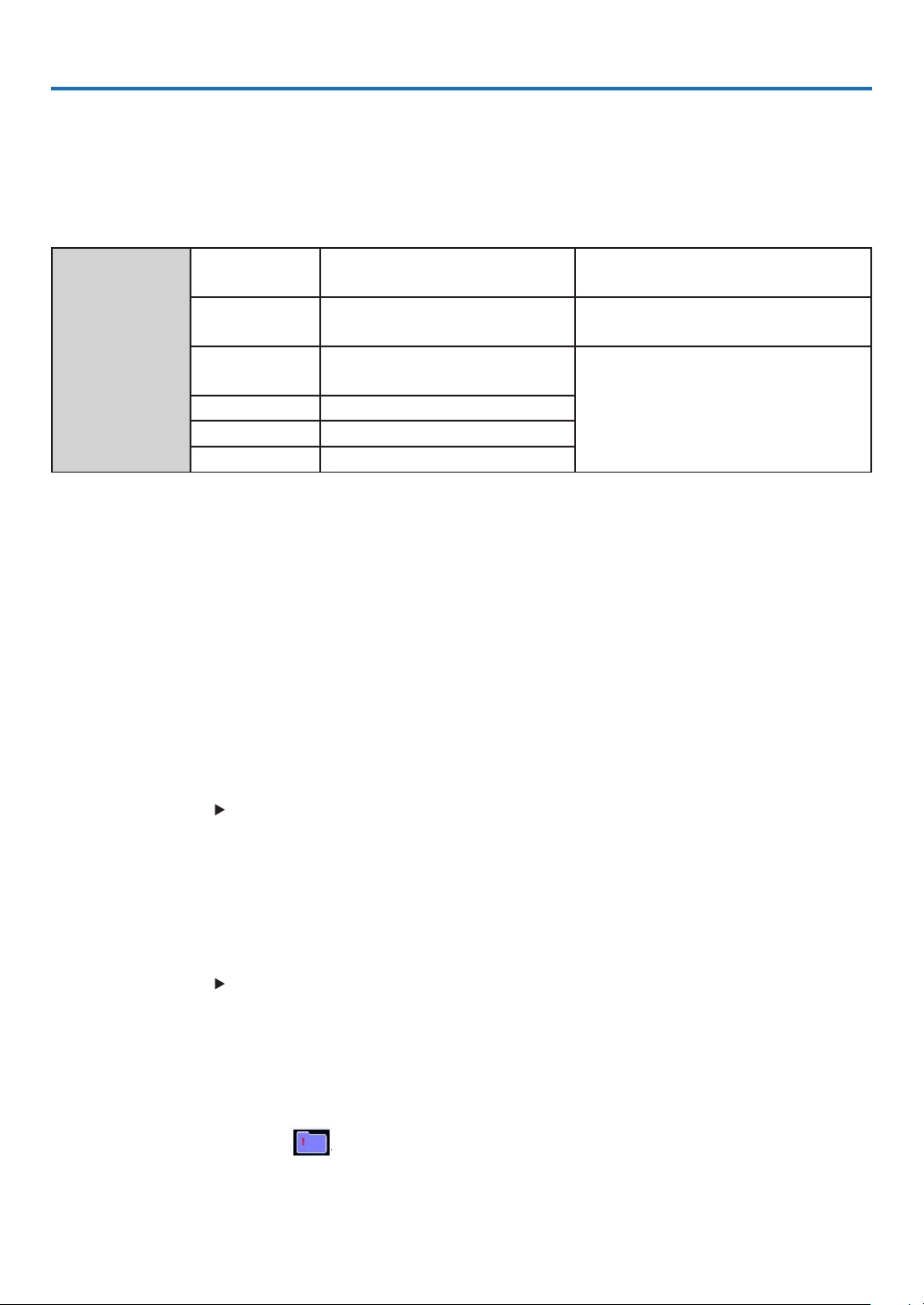
USB-A function supports the following picture files.
Maps
Extension
name
jpg/jpeg
bmp
Baseline encoder 24
Progressive RGB24 bit
1.4.8 bit palette-based
RGB24,32 bit
png 24, 48-bit True Color
Format Description
Max resolution: 10000x10000
Max resolution: Panel Resolution
Max resolution: 1280X800
gif 1,4,8-bit palette-based
tiff
Display USB-A screen
When the USB memory insert into the projector, the USB-A function can project pictures which is stored in the USB
memory.
1) Press SOURCE button on the remote control or INPUT on the top control, then select the input source of [USB-A].
2) Insert the USB memory into the USB Port (Type A) directly.
• Press the ENTER button to display standby screen instantly, while the USB memory icon display in the lower
left corner of the screen.
• When the USB memory is independent of the partition, it will display more than one USB icon.
3) Press ▲ ▼ button to switch required items.
• The root directory of the USB memory is displayed in a thumbnail.
Play image
Only one image show on the screen when you play it.
1) Press ▲ ▼ button to select a image.
2) Press the ENTER or button.
• Full screen display
3) Press the ENTER button.
• Press the ENTER button to return the thumbnail.
Play slide
Turn on set slide in the USB-A menu to play the file, other files in the same folder can play automatically.
1) Press button to select a file.
2) Press the ENTER or button.
• Full screen display.
3) Press the ENTER button.
• Press the ENTER button to return the thumbnail.
The termination of USB-A
The slide transition effect in the USB-A menu is set to "Slide right" or "Slide down", all images in the same folder
can play automatically.
1) Press ▲ ▼ button to select , displayed in the upper left corner of the screen.
2) Press the ENTER button.
3) Unplug the USB memory directly.
28
Page 47

4. Using the VIEWER
NOTE:
• Only USB memory up to FAT32 (32GB) can be read.
• When you insert a USB memory, please make sure insertion direction to avoid damaging the port.
• Please note the following points when inserting and removing USB memory:
a. The indicator flashes, when the USB memory insert into the projector or the projector is reading data. DO NOT remove the USB memory
when the light is flashing.
b. Do not insert and remove USB memory frequently. Then remove it after the installation of at least 5 seconds. After removing at least
5 seconds and then reinsert it.
c. Due to the file format, some pictures cannot display thumbnails.
Precautions on processing and storage of USB memory
• If smoke or produce abnormal smell, close the external device and contact the dealer.
• Do not put foreign matter or metal items in the USB port. Static electricity may cause data loss or data damage.
29
Page 48
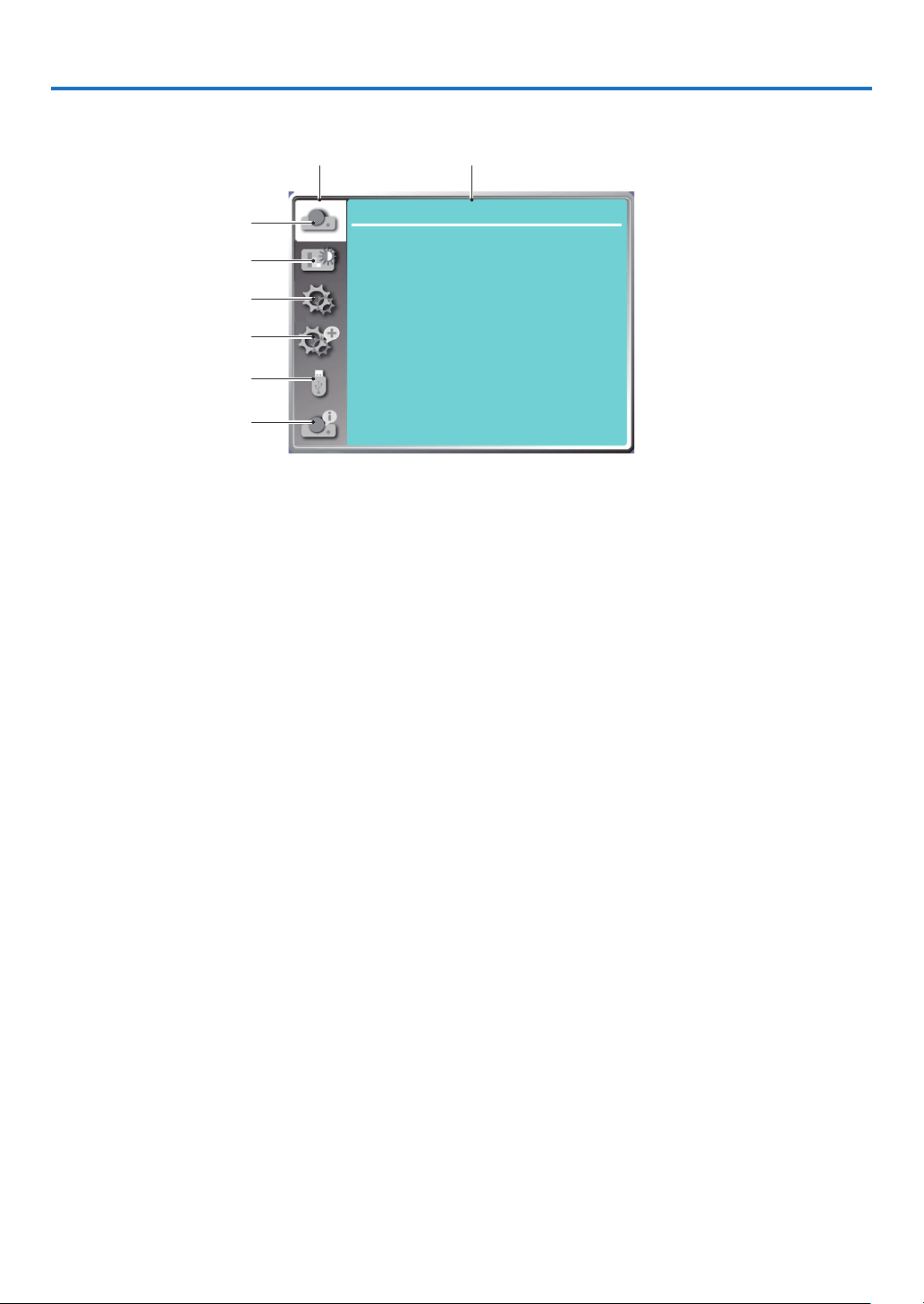
5. Using On-Screen Menu
❶ Menu item overview
Main menu Submemu
①
②
③
④
⑤
⑥
Display
Auto PC adj.
Fine sync 0
H position
V position
H.size
Aspect Normal
Orientation
Menu position
Background display
Signal format
Front
Upper left
Blue
0
0
0
...
1. Display menu
• Select Auto PC adj., Fine sync, H position, V position, H. size to adjust the parameters to match the VGA
format.
• Aspect: Normal/Wide/Full/4:3.
• Orientation: Choose Front, Auto ceiling/Rear, Auto ceiling/Front, Ceiling / Rear, Ceiling / Front and Rear.
• Menu position: Set screen menu display position on the screen.
• Background display: Set the background color of the projection screen.
• Signal format: Select the compatible system signal format with input source.
2. Color adjust menu
Available options in the Image mode menu are Dynamic, Standard, Cinema, Blackboard (Green), Color
board, or User image.
The available color adjust options: Contrast, Brightness, Color temp. , Red, Green, Blue and Sharpness.
3. Setting menu
Configuration of the basic function operation on the projector: On start, Standby mode, High altitude,
Cooling fast, Key lock, Baud rate, Contrast optimization, Laser control, Sound and HDMI setup.
4. Expand menu
Available adjust options are Language, Auto setup, Keystone, Security, Power management, Filter, Test
pattern, Network setup, Control ID and Factory default.
5. USB-A menu
Select parameter of Set slide, Slide transition effect, Sort order, Rotate, Best fit, Repeat, Apply.
6. Information menu
Display information about the projector.
30
Page 49
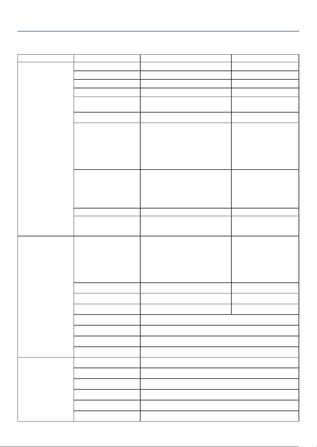
5. Using On-Screen Menu
❷ List of Menu Items
Some menu items are not available depending on the input source.
Main menu Sub-menu Setting Remarks
Auto PC adj.
Fine sync 0-31
H position -5 - +5
V position -5 - +5
The range of H. size
differs from signals.
The selected Signal format
displays in the Signal format menu
Display
Color adjust
H. Size -15 - +15
Aspect Normal*/Wide/Full/4:3
Front *
Rear
Orientation
Menu position
Background display Black,Blue*,Logo
Signal format ---
Image mode
Contrast
Brightness
Ceiling / Front
Ceiling / Rear
Auto ceiling / Front
Auto ceiling / Rear
Upper left*
Upper right
Center
Lower left
Lower right
Standard*
Cinema
Blackboard(Green)
Color board
User image
Dynamic
0-63 (32 *)
0-63 (32 *)
Color temp High/Mid*/Low/User
Red
Green
Blue
Sharpness
On start On/Off*
Standby mode Normal*/Sleep/Network standby
High altitude On/Off*
Setting
Cooling fast 60 Sec/0 Sec*/30 Sec
Key lock On/Off*
Contrast optimization
* The asterisk (*) indicates that the default setting varies depending on the signal.
0-63 (32 *)
0-63 (32 *)
0-63 (32 *)
0-15 (8 *)
On/Off*
31
Page 50
5. Using On-Screen Menu
Main menu Sub-menu Setting Remarks
Baud rate 4800/9600/19200*/38400
Normal*/ECO1/
Setting
ECO mode
Laser control
Laser adjust.
Volume 0-25(12 *)
Sound
Mute On/Off*
ECO2/Full
Normal
50%-100%
(100%*)
Only for Normal mode
Expand
HDMI setup
Language
Auto setup
Keystone
Security
Power management
Filter
Test pattern
Image
Sound
Projector provides multiple
language support (English*)
Input search On*/Off
Auto PC adj. On*/Off
Auto keystone On/Off*
Keystone Store* / Reset
H/V keystone
4-Corner correction
6-Corner correction
Curved correction
Grid image tune
Reset
PIN code lock On/Off*
PIN code change
Ready*
Shut down
Off
Timer
Ready countdown
Filter counter
Timer
Filter counter reset
Off*,Gray scale(1-4),Color bar,
Red, Green, Blue,
,White, Black,
Auto*/64-940/
0-1023
HDMI*/
Computer
Cross hatch
Raster gray
* The asterisk (*) indicates that the default setting varies depending on the signal.
32
Page 51
5. Using On-Screen Menu
Main menu Sub-menu Setting Remarks
DHCP(On/Off*)
IP address
Subnet
Gateway
DNS
Expand
Network setup
Network setting
Wired LAN
Wireless LAN Setting
Network information
MAC address
IP address
(On/Off*)
USB-A
Info.
Control ID
Control ID
Factory default
Set slide
Slide transition effect
Sort order
Rotate
Best fit On/Off*
Repeat On/Off*
Apply
Input
H- sync freq.
V- sync freq.
Light counter
Model name
Control ID
number
Slide down
Slide right*
Extend order
Name order*
Time order
Size order
No rotate*
270 degree
180 degree
90 degree
On/Off
*
1-254(1*)
S/N
Firmware version
SUBCPU
* The asterisk (*) indicates that the default setting varies depending on the signal.
33
Page 52

5. Using On-Screen Menu
❸ Menu Descriptions & Functions [INPUT]
Computer
HDMI 1
HDMI 2
USB-A
LAN
Computer
Selects the computer connected to your Computer input terminal signal.
NOTE: When the component input signal is connected to the COMPUTER IN terminal, select [Computer].
HDMI1 and HDMI2
Selects the HDMI compatible equipment connected to your HDMI1 or 2 IN terminal.
USB-A
This feature enables you to make presentations using a USB memory that contains pictures.
(→ page 28 “4. Using the VIEWER”)
LAN
Selects a signal from the LAN port (RJ-45).
34
Page 53
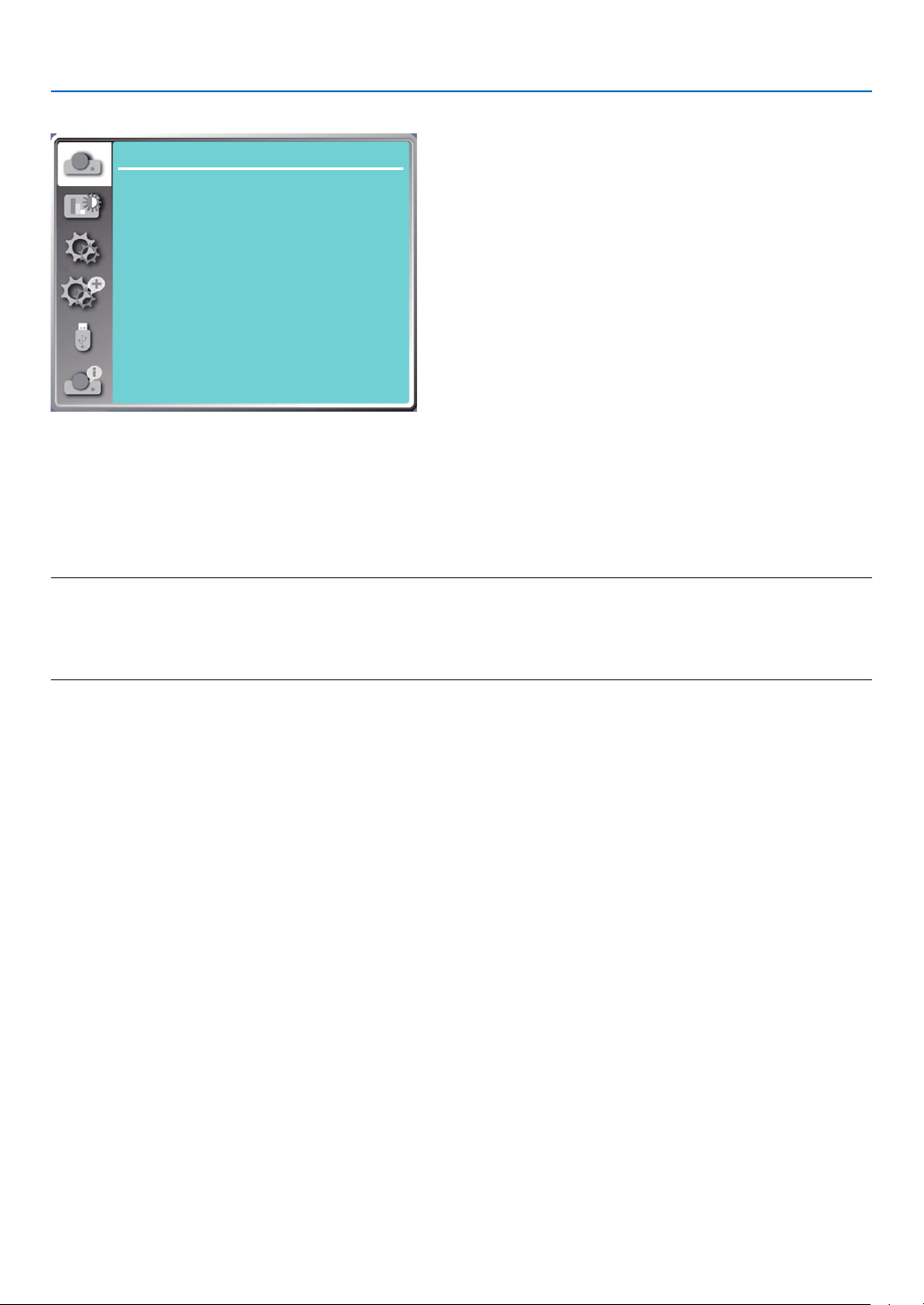
5. Using On-Screen Menu
❹ Menu Descriptions & Functions [Display menu]
Display
Auto PC adj.
Fine sync 0
H position
V position
H.size
Aspect Normal
Orientation
Menu position
Background display
Signal format
[Auto PC adj.]
Select Auto PC Adj. function can adjust Fine sync, H position, V position , H. size to be compatible with the computer automatically.
Press the MENU button on the remote control or on the top control panel to display the On-Screen menu.
Press ▲ ▼ button to select the Display menu, then press the ENTER or ▶ button.
1) Press ▲ ▼ button to select [Auto PC adj.] menu.
2) press the ENTER button.
NOTE:
• The projector will perform Auto PC adj. function automatically,when its signal is input for the first time.
• Auto PC adj. function may fail to work if computer models is not compatible with the input signal .
• Auto PC adj. function may fail to work if you select the following system signal format: 480i, 576i, 480p, 576p, 720p, 1080i,1080p, or
signals from the HDMI terminal.
0
0
0
Front
Upper left
Blue
...
[Fine sync]
(Only for PC signal input)
Adjust image to the best state When the image jitters, or the image outline dims.
1) Press ▲ ▼ button to select [Fine sync] menu.
2) Press the ENTER button.
3) Press ▲ ▼ button to adjust Fine sync.
Adjustment range is from 0 to +31. Please adjust to the least interference state.
[H position]
(Only for PC signal input)
On the premise that the relative position of both projector and the screen is set up right,you can move the image
horizontal position,if the position of the projected image on the screen is deviated.
1) Press ▲ ▼ button to select [H position] menu.
2) Press the ENTER button.
3) Press ▲ ▼ button to adjust image H position.
Adjustment range is from -5 to +5.
35
Page 54
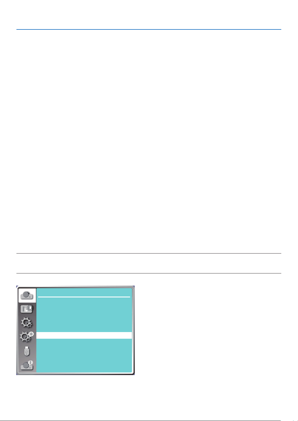
5. Using On-Screen Menu
[V position]
(Only for PC signal input)
On the premise that the relative position of both projector and the screen is set up right, you can move the image
vertical position, if the position of the projected image on the screen is deviated.
1) Press ▲ ▼ button to select [V position] menu.
2) Press the ENTER button.
3) Press ▲ ▼ button to adjust image V position.
Adjustment range is from -5 to +5.
[H. size]
(Only for PC signal input)
You can adjust and reduce the interference caused by patterns of the projected vertical stripes.The following projected patterns may cause a circular pattern (Noise). Adjust the amount of interference to the minimum. Users can
point the clock to adjust images.
1) Press ▲ ▼ button to select [H. size] menu.
2) press the ENTER button.
3) Press ▲ ▼ button to adjust H. size level .
Adjustment range is from -15 to +15.
[Aspect]
Adjust the image to fit the screen size, while keeping aspect of input signal's unchanged.
Press the MENU button on the remote control or on the top control panel to display the On-Screen menu. Press ▲
▼ button to select the Display menu, then Press the ENTER or ▶ button.
1) Press ▲ ▼ button to select [Aspect] menu.
2) Press the ENTER button.
3) Press ▲ ▼ button to select the required item.
Normal........... Use the maximum size to project while keeping the aspect of input signal's unchanged.
Wide............... Project images at the aspect of 16: 9.
Full..................Project images to the maximum.
4:3...................Project images at the aspect of 4:3.
16:10...............Project images at the aspect of 16:10.
NOTE:
• This projector can be selected from Normal / Wide / Full / 4:3.
• 16:10 will be grayed out on this projector.
Display
Auto PC adj.
Fine sync 0
H position
V position
H.size
Aspect Normal
Orientation
Menu position
Background display
Signal format
0
0
0
Front
Upper left
Blue
...
36
Page 55
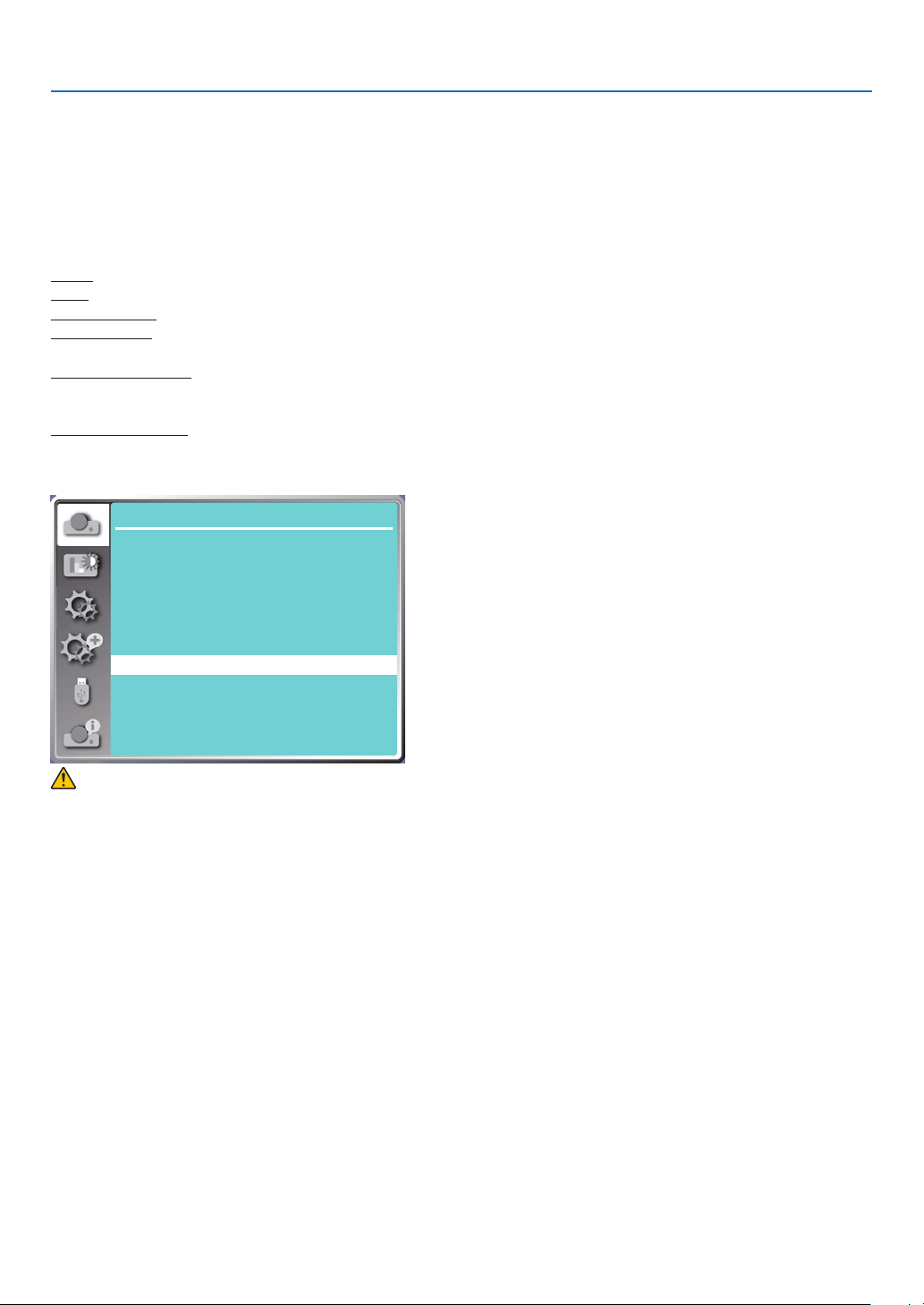
5. Using On-Screen Menu
[Orientation]
Select this function to set the project way.
Please change the projection way, if the On-Screen menu displays inversely or reversedly.
Press the MENU button on the remote control or on the top control panel to display the On-Screen menu. Press ▲
▼ button to select the Display menu, then press the ENTER or ▶ button.
1) Press ▲ ▼ button to select [Orientation] menu.
2) Press the ENTER button.
3) Press ▲ ▼ button to switch.
Front: When the projector is installed on the table and projected in front of the screen.
Rear: When the projector is installed on the table and projected in rear of the screen (using translucent screen)
Ceiling / Front: When use the ceiling mount (Commercially available) to lift the projector in front of the screen.
Ceiling / Rear: When use the ceiling mount (Commercially available) to lift the projector in rear of the screen (using
translucent screen).
Auto ceiling / Front: When the projector is projected in front of the screen. The built-in angle sensor detects the
angle of the projector automatically and then switches to [Front] or [Ceiling/Rear]. When front
projection, please set it to this option. (→ page 9 )
Auto ceiling / Rear: When the projector is projected in front of the screen. The built-in angle sensor detects the angle
of the projector automatically and then switches to [Rear] or [Ceiling/Rear]. When rear projection, please set it to this option.(→ page 9 )
Display
Auto PC adj.
Fine sync 0
H position
V position
H.size
Aspect Normal
Orientation
Menu position
Background display
Signal format
0
0
0
Front
Upper left
Blue
...
WARNING
• Should special works be required, for example to suspend the projector from the ceiling, consult your dealer.
• Never try to install the projector yourself in such cases. The projector could drop and cause injury.
[Menu position]
Select this function to set the On-Screen Menu position.
Press the MENU button on the remote control or on the top control panel to display the On-Screen menu. Press ▲
▼ button to select the display menu, then press the ENTER or ▶ button.
1) Press ▲ ▼ button to select [Menu position] menu.
2) Press the ENTER button.
3) Press ▲ ▼ button to change menu position.
Upper left ......The menu display on the upper left corner of the screen.
Upper right ....The menu display on the upper right corner of the screen.
Center............The menu display in the center of the screen.
Lower left ......The menu display on the lower left corner of the screen.
Lower right ....The menu display on the lower right corner of the screen.
37
Page 56
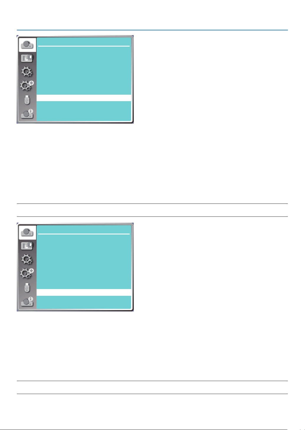
5. Using On-Screen Menu
Display
Auto PC adj.
Fine sync 0
H position
V position
H.size
Aspect Normal
Orientation
Menu position
Background display
Signal format
0
0
0
Front
Upper left
Blue
...
[Background display]
Select this function can adjust background color when there is no input signal.
Press the MENU button on the remote control or on the top control panel to display the On-Screen menu. Press ▲
▼ button to select the Display menu, then press the ENTER or ▶ button.
1) Press ▲ ▼ button to select [Background display] menu.
2) Press the ENTER button.
3) Press ▲ ▼ button to select required item .
Blue....... The entire projection area display blue.
Black......The entire projection area display black.
Logo.......The entire projection area display NEC PROJECTOR background.
NOTE:
• This function will be invalid once you select input signal as USB-A and LAN.
Display
Auto PC adj.
Fine sync 0
H position
V position
H.size
Aspect Normal
Orientation
Menu position
Background display
Signal format
0
0
0
Front
Upper left
Blue
...
[Signal format]
If a PC is selected as the input signal source, your projector will detect and adapt to its signal format automatically.
Correct image can be displayed without any setup operation.
Your projector will display one of the following:
Auto: The Auto PC Adjusting function will make necessary adjustment to your projector to project valid images. If
images are displayed incorrectly, adjust it manually.
---- : No PC signals detected. Check the connection between PC and your projector.
NOTE:
• Your projector may save data generated by the Auto PC adj. function.
38
Page 57
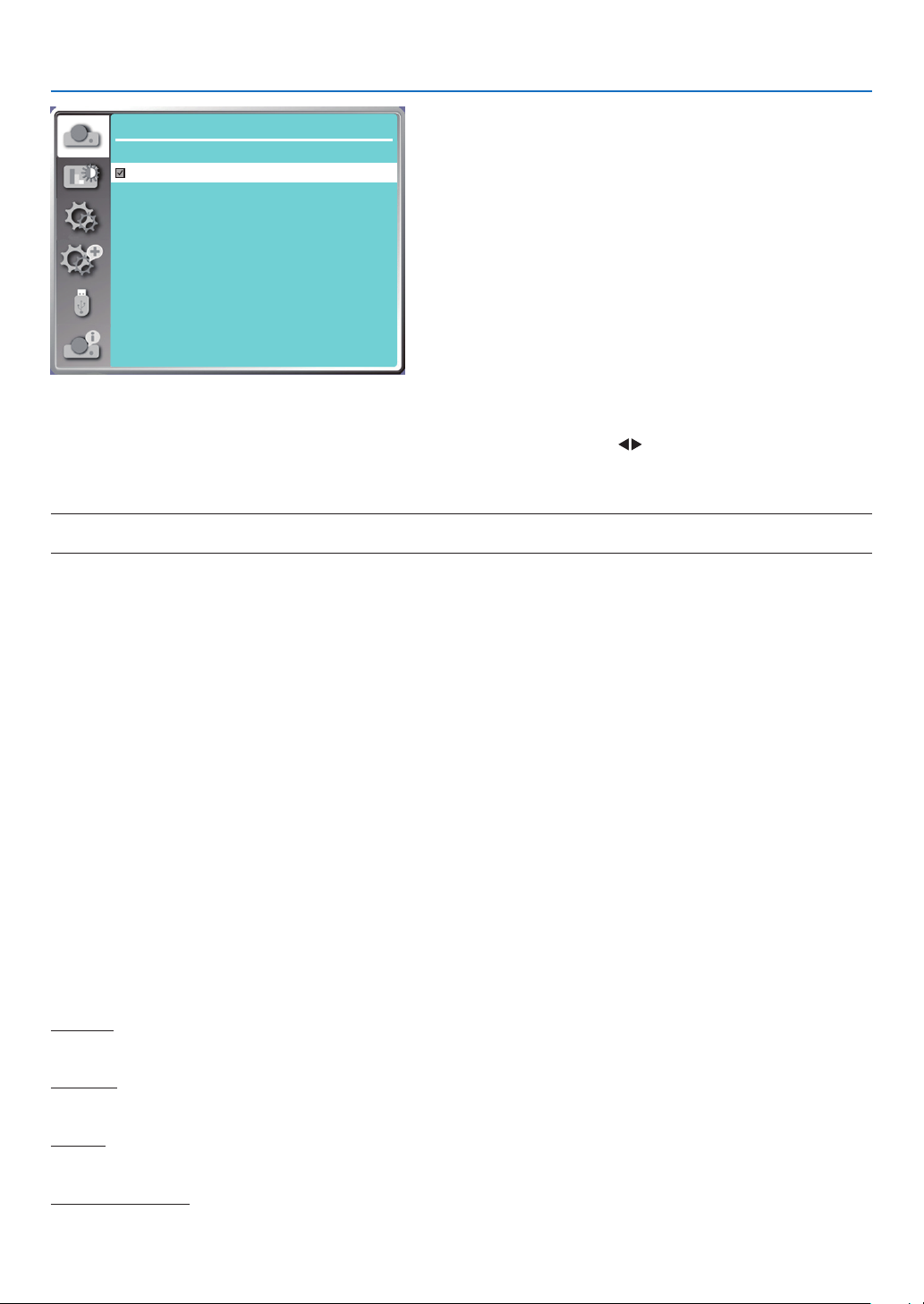
5. Using On-Screen Menu
Display
Signal format
1024 x 768 , 60 HZ
1280 x 800 , 60 HZ
1920 x 1080 , 60 HZ
- - - -
- - - -
• The selected Signal format displays in the Signal format menu.
Select the computer Signal format manually.
1. Press the MENU button on remote control and the On-Screen displays. Press button to point to the Input icon,
press ▲ ▼ button or the ENTER button and the Input menu displays.
2. Press ▲ ▼ button to select Signal format, then press ENTER button.
NOTE:
• The computer Signal format menu will be disabled once HDMI 1, HDMI 2, USB-A, LAN has been selected.
❺ Menu Descriptions & Functions [Color adjust]
Select color adjustment to set the image mode and adjust the quality of the projected image.
Menu operation
Press the MENU button on the remote control or on the top control panel to display the On-Screen menu. Press ▲
▼ button to select the Color adjust menu, then press the ENTER or ▶ button.
1) Press ▲ ▼ button to select required item.
2) Press the ENTER button.
3) Press ▲ ▼ button to select adjust set point.
[Image mode]
Direct operation
Press the PICTURE select button on remote control to select required image mode.
Menu operation
Press the MENU button on the remote control or on the top control panel to display the On-Screen menu. Press ▲
▼ button to select the color adjust menu, then press the ENTER or ▶ button.
1) Press ▲ ▼ button to select [Image mode] menu.
2) Press the ENTER button.
3) Press ▲ ▼ button to select required item.
Dynamic
An image mode suitable for viewing in bright room.
Standard
The default mode of your projector, can come to natural color.
Cinema
Enriched gray scale for viewing movies.
Blackboard (Green)
An image mode designed for displaying on a blackboard (Green). It boosts quality of image projected on blackboard
39
Page 58
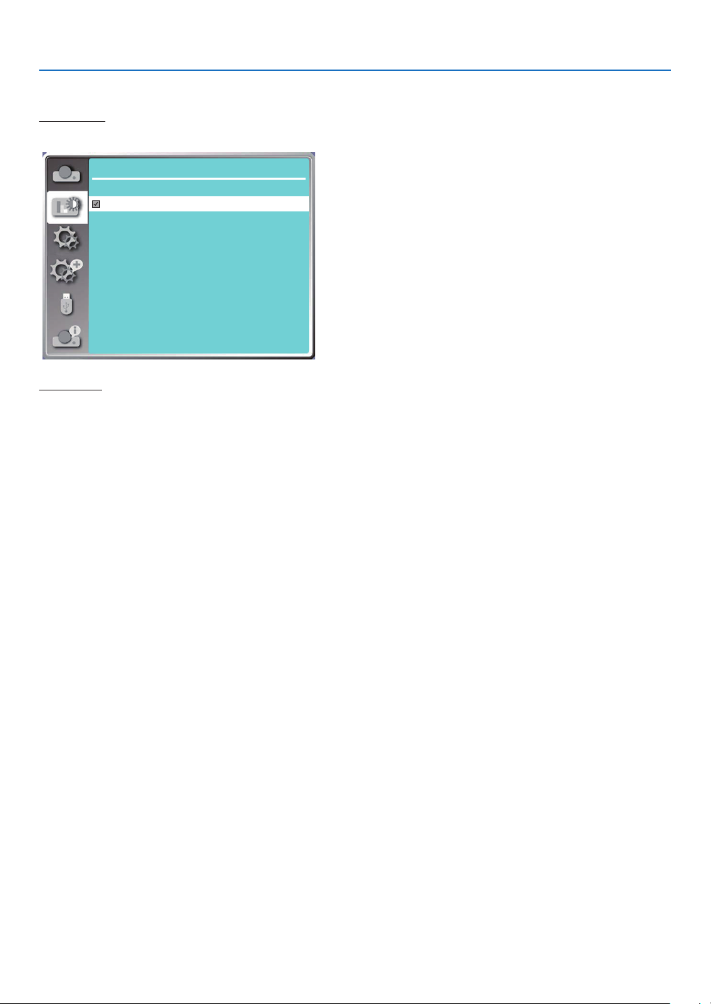
5. Using On-Screen Menu
(Green). This is designed for a board in green rather than black as indicated by its name.
Color board
A image mode suitable for image projecting on surface of wall in red, blue, yellow or green. Press the ENTER button
to enter Color board menu, then press ▲ ▼ button to select Red, Blue, Yellow or Green, press the ENTER button.
Color adjust
Colorboard
Red
Blue
Green
Yellow
User image
Users can customize the color adjustment.
[Contrast]
Press ▼ button to decrease contrast, range from 0 - +63.
Press ▲ button to increase contrast, range from 0 - +63.
[Brightness]
Press ▼ button to decrease brightness, range from 0 - +63.
Press ▲ button to increase brightness, range from 0 - +63.
[Color temp.]
Press ▲ ▼ button to select required color temperature (Low, Mid., High and User)
High temp: Become blue gradually.
Mid temp: Suitable natural color.
Low temp: Become red gradually.
User:You can adjust the Red, Green, Blue and Yellow values by yourself.
[Red]
Press ▼ button to decrease red tint and ▲ button to increase it.
[Green]
Press ▼ button to decrease green tint and ▲ button to increase it.
[Blue]
Press ▼ button to decrease blue tint and ▲ button to increase.
[Sharpness]
Press ▼ button to soften image and ▲ button to sharpen, range from 0 - +15.
40
Page 59
5. Using On-Screen Menu
Color adjust
Image mode
Contrast
Brightness
Color temp.
Red
Green
Blue
Sharpness
Standard
32
32
Mid
32
32
32
0
6 Menu Descriptions & Functions [Setting]
The projector has setting function, you can select other functions as described below.
Menu operation
Press the MENU button on the remote control or on the top control panel to display the On-Screen menu. Press ▲
▼ button to select the setting menu, then press the ENTER or ▶ button.
1) Press ▲ ▼ button to select required item.
2) Press the ENTER button.
3) Press ▲ ▼ button to set options.
Setting
On start
Standby mode
High altitude
Cooling fast 60 Sec
Key lock
Contrast optimization
Baud rate
Laser control
Sound
HDMI setup
Off
Normal
Off
Off
Off
9600
[On start]
Set the option to "On" if selecting this function, the projector will automatically turn on when the power cord is connected to the power outlet.
1) Press ▲ ▼ button to select [ On start ] menu.
2) Press the ENTER button.
3) Press ▲ ▼ button to select required item.
Off...... Get into standby mode.
On.......Start up immediately.
41
Page 60
5. Using On-Screen Menu
Setting
On start
Standby mode
High altitude
Cooling fast 60 Sec
Key lock
Contrast optimization
Baud rate
Laser control
Sound
HDMI setup
Off
Normal
Off
Off
Off
9600
Note:
• After the power is turned off, please wait about 20s after unplugging the AC, and then you can turn on the power. If the power is turned
on immediately, it may not work properly.
[Standby mode]
Select this function to switch different standby mode.
1) Press ▲ ▼ button to select [Standby mode] menu.
2) Press the ENTER button.
3) Press ▲ ▼ button to adjust levels.
Normal...... Although the power consumption on this mode is lower than on the [Network standby] or [Sleep] mode,
when this mode is selected, only the POWER button on the top control panel or the remote control will work..
Network standby...... Although the power consumption on this mode is higher than on the [Normal] mode, this mode
allows you to turn on the projector from standby condition by using the Wake on LAN feature
(hereafter referred to as WoL) via LAN.
Consult your network administrator for more information about WoL.
Sleep ........ Although the power consumption on this mode is higher than on the [Network standby] mode, this mode
spends less time to turn on the projector from standby condition via LAN compared to the [Network
standby] mode.
To control the projector by using our application software NaViSet Administrator 2, select the [Sleep]
mode.
Setting
On start
Standby mode
High altitude
Cooling fast 60 Sec
Key lock
Contrast optimization
Baud rate
Laser control
Sound
HDMI setup
Off
Normal
Off
Off
Off
9600
[High altitude]
You can change the setting about speed of cooling fan according to the altitude your projector is operating at.
1) Press ▲ ▼ button to select [High altitude] menu.
42
Page 61
5. Using On-Screen Menu
2) Press the ENTER button.
3) Press ▲ ▼ button to select required menu.
Off: Normal speed. set the option off when operating the operator, if the altitude is not too high.
On: Faster than when in off mode .set the option on when operating the operator in high land.
Setting
On start
Standby mode
High altitude
Cooling fast 60 Sec
Key lock
Contrast optimization
Baud rate
Laser control
Sound
HDMI setup
Note:
• The air pressure sensor will sense the altitude automatically. When the altitude is at an altitude of approximately 1700 meters/ 5577 feet
or higher, projector will turn on the High altitude function automatically, thus the On-screen menu of High altitude will change to "On".
• If the air pressure sensor is damaged, the projector OSD menu will turn red for reminding that the automatic transfer to high altitude
function is invalid. User could set High altitude to "On" manually .
• When setting condition is over approximately 2600 meters / 8530 feet , automatically brightness is reduced to protect unit.
• This unit can be used at approximately 3000 meters / 9843 feet , once over that altitude units automatically turn down to protect unit.
Off
Normal
Off
Off
Off
9600
[Cooling fast]
Select the cooling time after projector is turned off.
1) Press ▲ ▼ button to select [Cooling fast] menu.
2) Press the ENTER button.
3) Press ▲ ▼ button to switch required menu.
60 Sec.....Cooling down in 60 seconds after the projector is turned off.
30 Sec...... Cooling down in 30 seconds after the projector is turned off. And the cooling fan will runs faster then in
the normal cooling way with shorter time but it will sounds louder.
0 Sec.......Cooling down instantly after the projector is turned off.
Setting
On start
Standby mode
High altitude
Cooling fast 60 Sec
Key lock
Contrast optimization
Baud rate
Laser control
Sound
HDMI setup
Note:
• Cooling fast function depends on whether user needs to move the projector immediately. If the user needs to unplug the power to
move the projector immediately, you can choose “0 Sec”, or we can select the "60 Sec" option.
Off
Normal
Off
Off
Off
9600
43
Page 62
5. Using On-Screen Menu
[Key lock]
Select this function to lock and unlock the control panel keypads. 1) Press ▲ ▼ button to select [Key lock] menu.
2) Press the ENTER button.
3) Press ▲ ▼ button to switch required menu.
Off......The control panel keypads are effective.
On......The control panel keypads is invalid.
NOTE:
• When you lock the top of the control panel keypads, but the remote control is lost or something wrong with it, please contact your dealer
or service center.
Setting
On start
Standby mode
High altitude
Cooling fast 60 Sec
Key lock
Contrast optimization
Baud rate
Laser control
Sound
HDMI setup
Off
Normal
Off
Off
Off
9600
[Contrast optimization]
Select this function to optimize and compensate signal automatically on the basis of the image, to get the best
contrast image.
1) Press ▲ ▼ button to select [Contrast optimization] menu.
2) Press the ENTER button.
3) Press ▲ ▼ button to adjust.
Off......No optimization.
On......Optimize contrast.
Setting
On start
Standby mode
High altitude
Cooling fast 60 Sec
Key lock
Contrast optimization
Baud rate
Laser control
Sound
HDMI setup
Off
Normal
Off
Off
Off
9600
[Baud rate]
Select this function to adjust the projector transmission rate.
1) Press ▲ ▼ button to select [Baud rate] menu.
2) Press the ENTER button.
44
Page 63
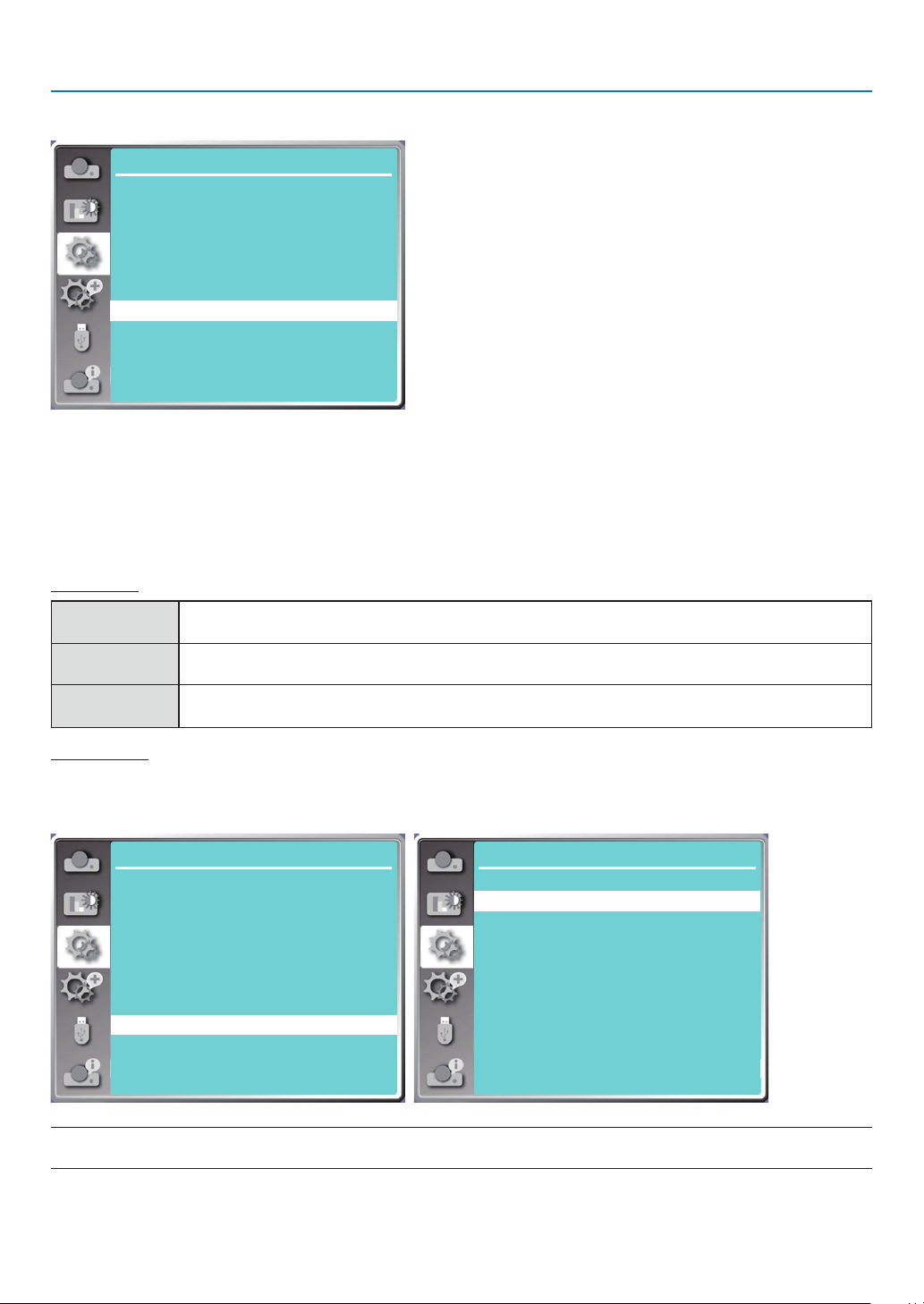
5. Using On-Screen Menu
3) Press ▲ ▼ button to select rate: 4800/9600/19200/38400.
Setting
On start
Standby mode
High altitude
Cooling fast 60 Sec
Key lock
Contrast optimization
Baud rate
Laser control
Sound
HDMI setup
Off
Normal
Off
Off
Off
9600
[Laser control]
Change light source brightness according to the environment and aim your projector is operating.
1) Press ▲ ▼ button to select [Laser control] menu.
2) Press the ENTER button.
3) Press ▲ ▼ button to select [ECO mode] or [Laser adjust].
4) Press the ENTER button.
ECO mode
Normal
Normal brightness, the screen becomes brighter. Alternatively, you can adjust from
50%~100%. Default is 100%.
ECO.1/ECO.2 Lower the brightness and reduce energy consumption.
Full normal
The brightness is the same as normal mode, but it is not adjustable
Laser adjust
This function is valid only in Normal mode, and the adjustable range is 50%-100%. And the menu will turn gray on
ECO.1, ECO2 and Full normal mode.
Setting
On start
Standby mode
High altitude
Cooling fast 60 Sec
Key lock
Contrast optimization
Baud rate
Laser control
Sound
HDMI setup
Off
Normal
Off
Off
Off
9600
NOTE:
• Laser adjust option can be chosen only in Normal mode.
Setting
ECO mode
Laser adjust
Laser control
Normal
100%
45
Page 64
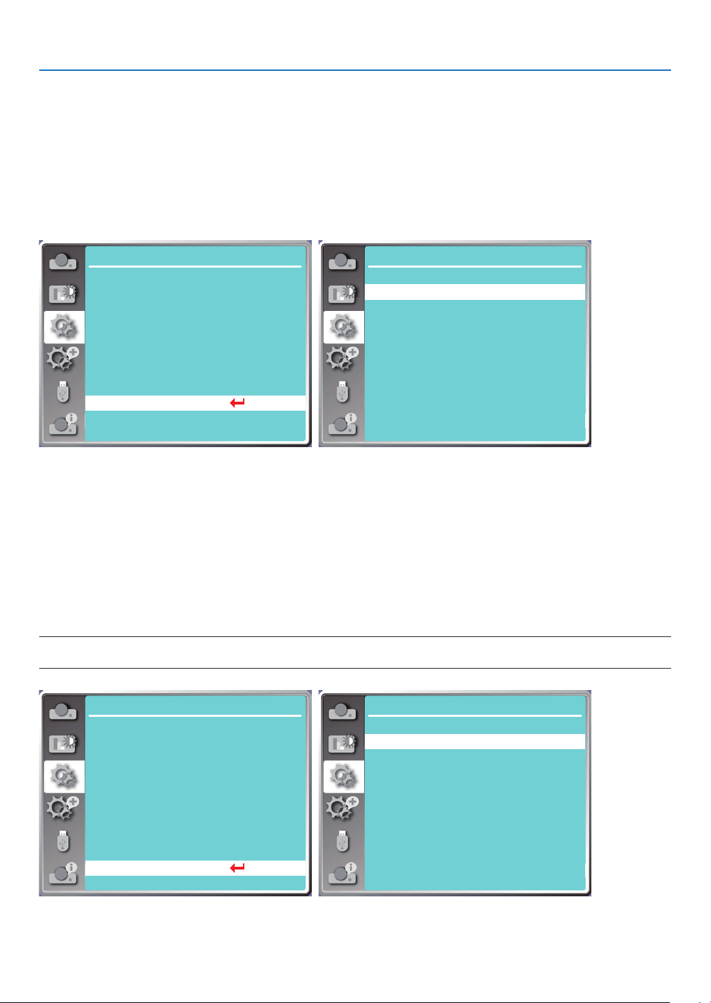
5. Using On-Screen Menu
[Sound]
Select this function to adjust the sound.
1) Press ▲ ▼ button to select [Sound] menu.
2) Press the ENTER button.
3) Press ▲ ▼ button to switch required menu.
Volume......Press ◀ button to turn down the volume and ▶ button to turn up the volume, range from 0 - +25
Mute..........Select "Off" to output audio, and select "On" to disable audio.
Setting
On start
Standby mode
High altitude
Cooling fast 60 Sec
Key lock
Contrast optimization
Baud rate
Laser control
Sound
HDMI setup
Normal
9600
...
Off
Off
Off
Off
Setting
Volume
Mute
Sound
12
Off
[HDMI setup]
When the external device is connected to the HDMI terminal of the projector, and the images can not be projected
normally, please switch on the image or sound setting.
Press the MENU button on the remote control or on the top control panel to display the On-Screen menu. Press ▲
▼ button to select the setting menu, then press the ENTER or ▶ button to enter the sub-menu.
1) Press ▲ ▼ button to select [HDMI setup] menu.
2) Press the ENTER button.
• Display [HDMI setup] instantly.
3) Press ▲ ▼ button to select [Image] or [Sound]].
4) Press the ENTER button.
NOTE:
• HDMI setup option can be chosen only in HDMI 1 and HDMI 2 channel.
Setting
On start
Standby mode
High altitude
Cooling fast 60 Sec
Key lock
Contrast optimization
Baud rate
Laser control
Sound
HDMI setup
Normal
9600
...
Off
Off
Off
Off
Setting
HDMI setup
Image
Sound
0-1023
HDMI
46
Page 65
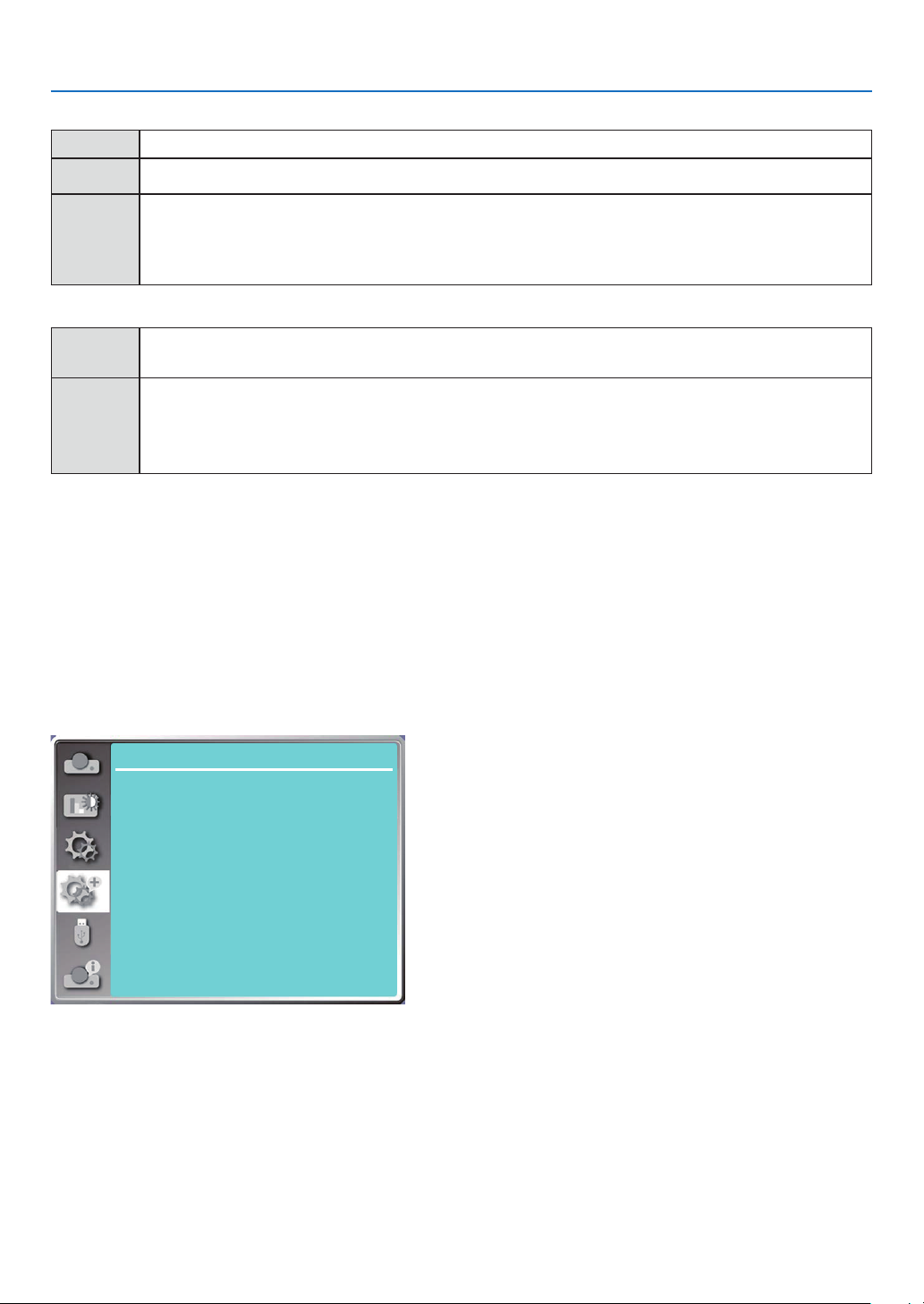
Image
Auto Set the signal level automatically.
[
64-940
] When external device (such as: a Blu-ray Disc player) is connected to the HDMI setup terminal .
When the output of an external device (such as a computer), via a conversion cable or a similar cable,
[
0-1023
is connected to the HDMI setup terminal.
]
Select this option
when
minal also.
Sound
the output of
5. Using On-Screen Menu
the PC or any other device is connected to the HDMI setup ter-
[
HDMI
When connect to the HDMI cable to transmit images and audio while the users do not need connect
]
to audio signal separately.
When the output of an external device (such as a computer), via a conversion cable or a similar
cable ,
[
Computer
]
is connected to the HDMI terminal .
The audio signal would be output according the connection of AUDIO IN terminal.
❼ Menu Descriptions & Functions [Expand]
The projector has expand function, you can select other functions as described below.
Menu operation
Press the MENU button on the remote control or on the top control panel to display the On-Screen menu. Press ▲
▼ button to select the Expand menu, then press the ENTER or ▶ button.
1) Press ▲ ▼ button to select required item.
2) Press the ENTER button.
3) Press ▲ ▼ button to set options.
4) Press the ENTER button.
Expand
Language
Auto setup
Keystone
Security
Power management
Filter
Test pattern
Network setup
Control ID
Factory default
[Language]
Users can selected the language displayed on the screen.
1) Press ▲ ▼ button to select [Language] menu.
2) Press the ENTER button.
3) Press ▲ ▼ button to select required language.
4) Press the ENTER button.
Various menus, settings, adjustment screens, names of control panel keypads, etc., will be displayed in the selected
language.
47
Page 66
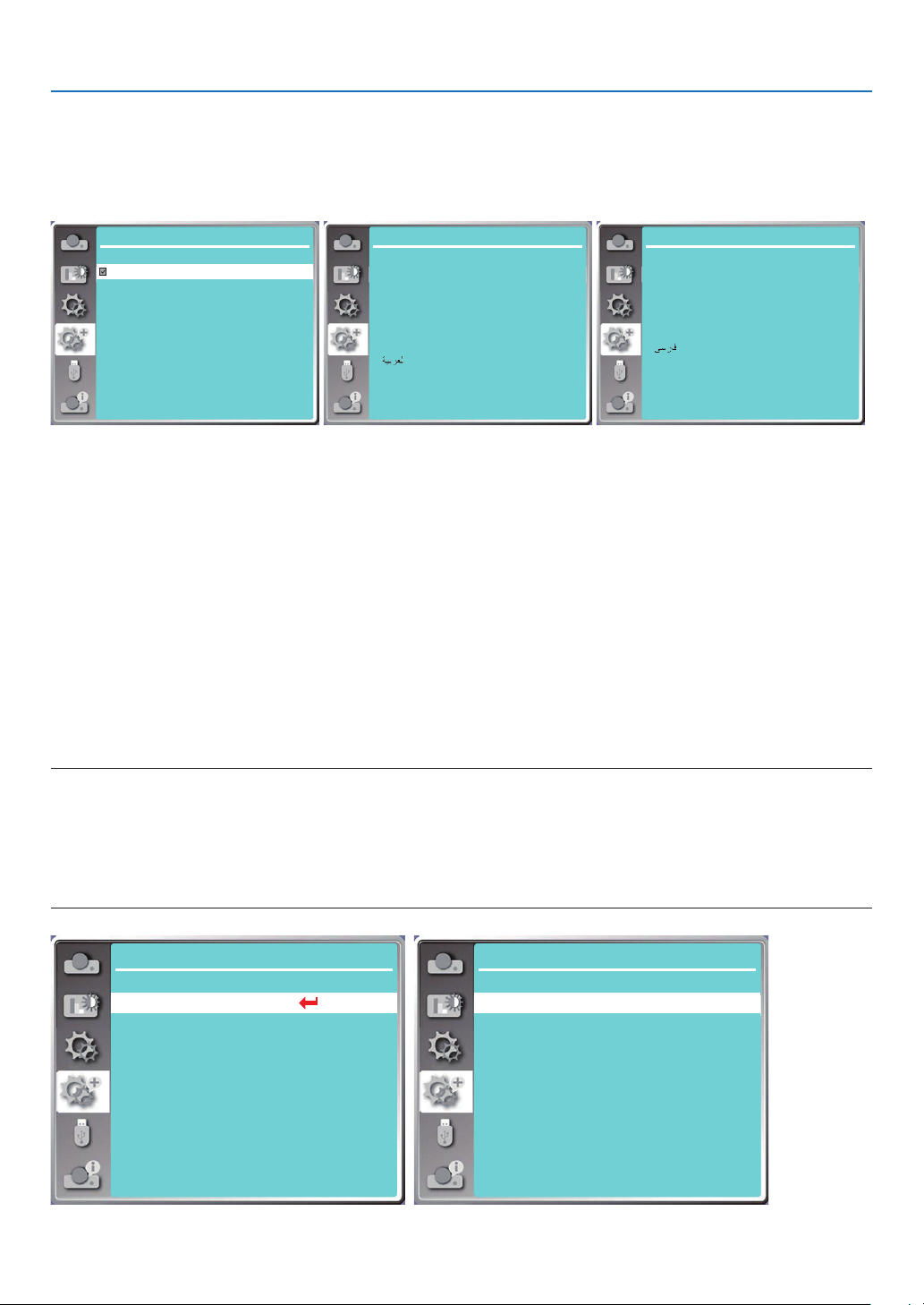
5. Using On-Screen Menu
Your projector comes with multiple language support. You may select required one from them, such as: English,
German, French, Italian, Spanish, Polish, Swedish, Dutch, Portuguese, Japanese, Simplified Chinese, Traditional
Chinese, Korean, Russian, Arabic, Turkey, Finland, Norway, Denmark, Indonesia, Hungary, Czech Republic, Kazakhstan, Vietnamese, Thai, Farsi, Romania.
Expand
English
Deutsch
Français
Italiano
Español
Português
Nederlands
Svenska
Suomi
Norsk
Language 1/3
Expand
Dansk
Polski
český
Magyar
Русский
Türkçe
Қазақ
Tiếng Việt
한글
Language 2/3
Expand
Language 3/3
日本語
ภาษาไทย
中文繁体
中文
Bahasa Indonesia
Română
[Auto setup]
Select this function to store or reset the keystone or some related setting after unplugging the AC power.
Press the MENU button on the remote control or on the top control panel to display the On-Screen menu. Press ▲
▼ button to select the Expand menu, then press the ENTER or ▶ button.
Press the AUTO ADJ. button on your remote control to execute the following functions: Input search, Auto PC adj.
and Auto keystone.
1) Press ▲ ▼ button to select [Auto setup] menu.
2) Press the ENTER button.
3) Press ▲ ▼ button to select required items.
Input search: Select this function to detect the signal, then project images automatically.
Auto PC adj.: When Auto PC adj. is set to "On", the projector inputs an analog signal, then press the "Auto ADJ."
button on the remote control to adjust [Fine sync], [H.Position], [V position] and [H. size] automatically.
When Auto PC Adjust is set to "Off", the "Auto ADJ." button on the remote control is invalid.
Auto keystone: Select this function to correct vertical distortion of the projected image automatically.
NOTE:
• Please adjust the projector manually, if the image is displayed abnormal even if you have selected Auto keystone function.
• When you set Project way as Ceiling / Front or Ceiling / Rear, Auto keystone function is invalid.
• When you set Project way as Auto ceiling / Front or Auto ceiling / Rear, and users put their projector in ceiling state, the Auto keystone
function will be invalid.
• When select auto search for input source search, USB-A and LAN signals are not in the scope of auto search function.
• Input search function does not support signal input from BNC to VGA.
Expand
Language
Auto setup
Keystone
Security
Power management
Filter
Test pattern
Network setup
Control ID
Factory default
...
Expand
Input search
Auto PC adj.
Auto keystone
Auto setup
On
On
Off
48
Page 67
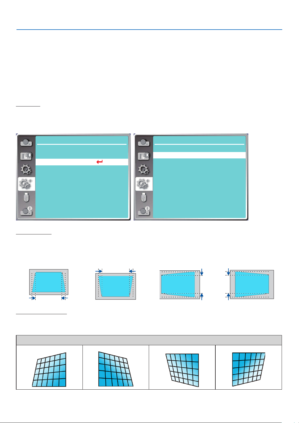
5. Using On-Screen Menu
[Keystone]
Select this function to store or reset the keystone or some related setting after unplugging the AC power cord.
Press the MENU button on the remote control or on the top control panel to display the On-Screen menu. Press ▲
▼ button to select the expand menu, then press the ENTER or ▶ button to enter.
1) Press ▲ ▼ button to select [Keystone] menu.
2) Press the ENTER button.
3) Press ▲ ▼ button to select required item.
4) Press the ENTER button.
Keystone
Select this function to store and reset keystone after turning off the projector or unplugging the AC power cord.
Store......Store keystone after turning off the projector or unplugging the AC power cord.
Reset......Keystone function will be canceled after turning off the projector or unplugging the AC power.
Expand
Language
Auto setup
Keystone
Security
Power management
Filter
Test pattern
Network setup
Control ID
Factory default
...
Expand
Keystone
H/V Keystone
4-Corner correction
6-Corner correction
Curved correction
Grid image tune
Reset value
H/V Keystone
Select this function to correct the projected images horizontally or vertically.
Press ▲ button to
reduce upper width
Press ▼ button to
reduce bottom width
Press ▶ button to
reduce left width
StoreKeystone
Press ▶ button to
reduce right width
4-Corner correction
Select this function to correct the projected images of four corners distorted.
Press ▲ ▼ ▶ ▶ button to keystone at four corners of the screen. The four corners are looped in sequence shown below:
Corner correction
Upper left Upper right Bottom left Bottom right
49
Page 68
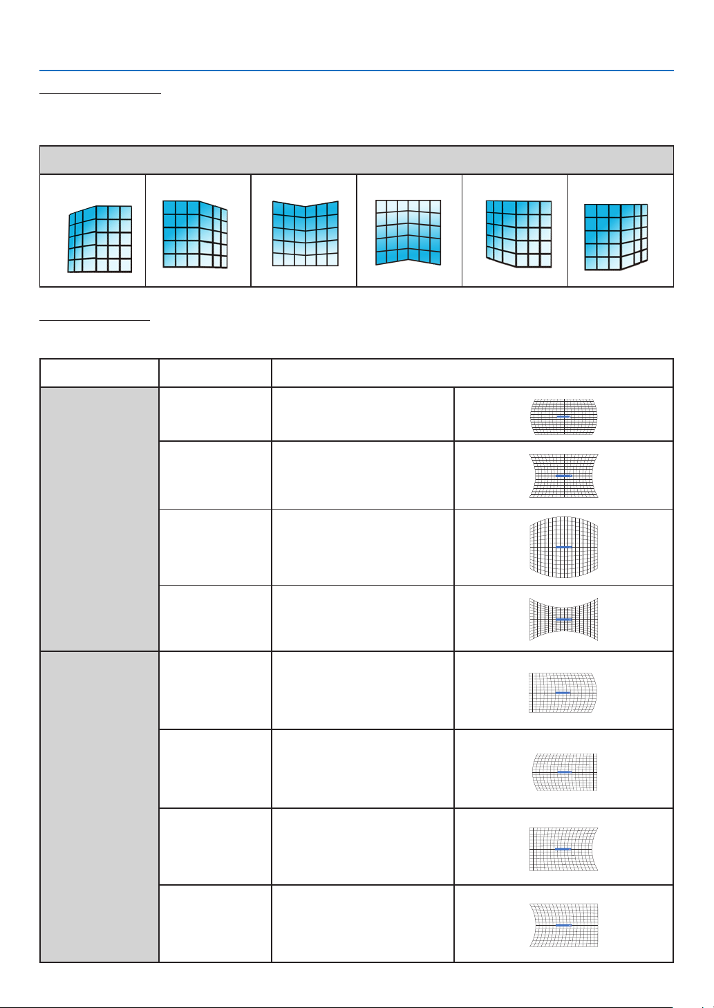
5. Using On-Screen Menu
Curved cerrection X/Y gain
6-Corner correction
Select this function to correct the projected images of six corners distorted.
Press ▲ ▼ ▶ ▶ button to keystone at six corners of the screen. The six corners are looped in sequence shown below:
Corner correction
Upper left Upper right Upper middle Bottom middle Bottom left Bottom right
Curved correction
Select this function to correct the projected images with linearity uneven or vertical and horizontal bending deformation.
press ▲ ▼ ▶ ▶ button to adjust options.
Item Operation Adjustment
Curved correction
X/Y gain
Curved correction
X offset
Press
Press
Press
Press
Press
Press
Press
Press
▼
The lines on the left and right
sides expand outward.
The lines on the left and right
sides shrink inward.
The top and bottom lines
expand outward.
The top and bottom lines shrink
inward.
Correct the vertical line on the
left.
Extend the left vertical line
outward while maintaining the
right area.
Correct the vertical line on the
right.
Expand the right vertical line
outward while maintaining the
left area.
Correct the vertical line on the
left.
Extend the left vertical line
outward while maintaining the
right area.
Correct the vertical line on the
right.
Expand the right vertical line
outward while maintaining the
left area.
50
Curved cerrection X/Y gain
Curved cerrection X/Y gain
Curved cerrection X/Y gain
Curved cerrection X Offset
Curved cerrection X Offset
Curved cerrection X Offset
Curved cerrection X Offset
Page 69
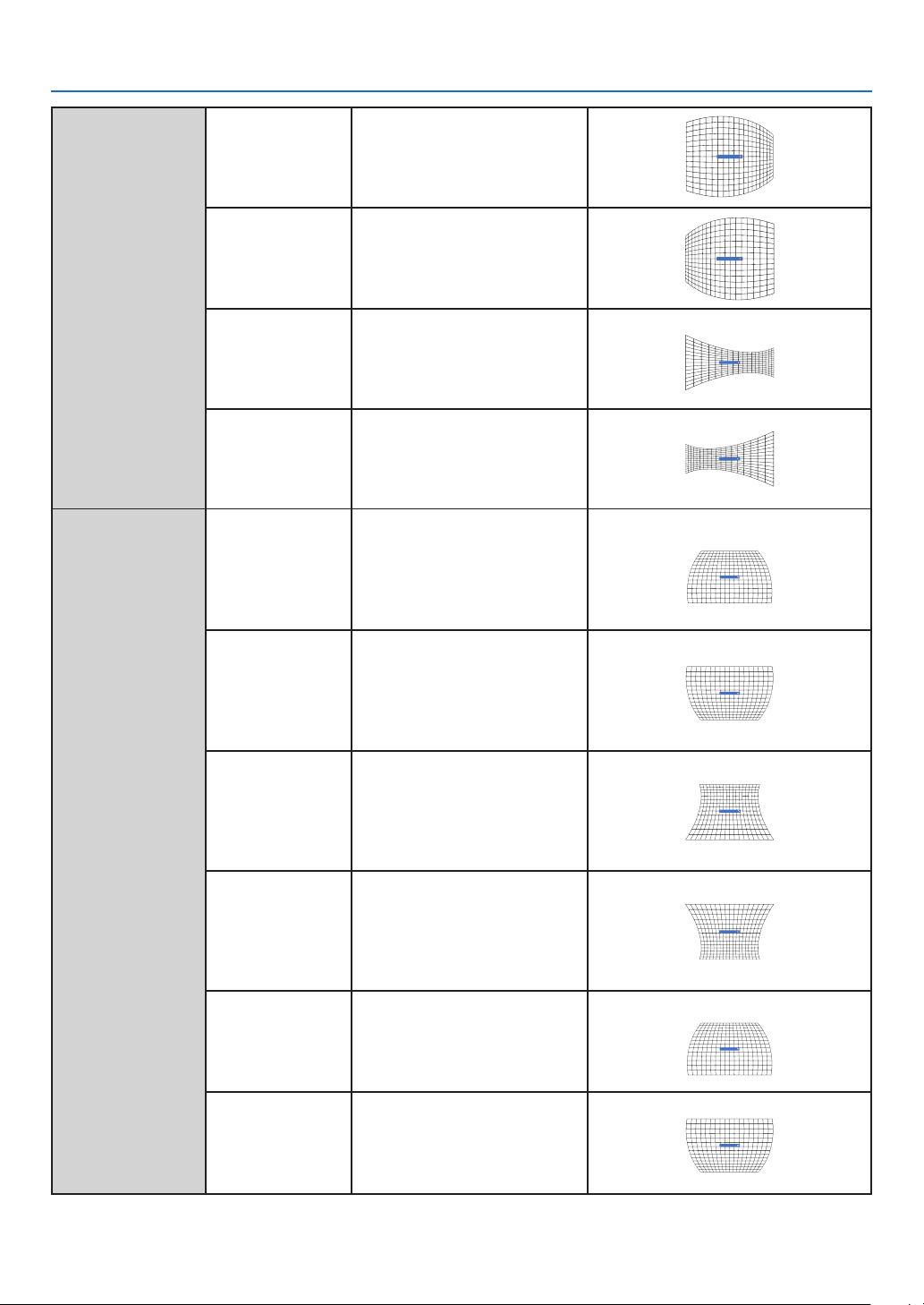
Curved correction
X offset
Curved correction
Y offset
Press
Press
Press
Press
Press
Press
Press
Press
Press
Press
▼
▼
▼
Correct the horizontal line on
the left.
While maintaining the right area,
expand the left top and bottom
horizontal lines outward.
Correct the horizontal line on
the right.
While maintaining the left area,
expand the top and bottom
horizontal lines on the right.
Correct the horizontal line on
the left.
While maintaining the right area,
expand the top and bottom
vertical lines on the left.
Correct the horizontal line on
the right.
While maintaining the left area,
expand the top and bottom
horizontal lines on the right.
Correct the vertical lines on the
left and right sides.
Extend the vertical lines on
the left and right sides of the
bottom while maintaining the
top area.
Correct the vertical lines on the
left and right sides.
Extend the vertical lines on the
left and right sides of the top
while maintaining the bottom
area.
Correct the vertical lines on the
left and right sides.
Extend the vertical lines on
the left and right sides of the
bottom while maintaining the
top area.
Correct the vertical lines on the
left and right sides.
Extend the vertical lines on the
left and right sides of the top
while maintaining the bottom
area.
Correct the horizontal line at the
bottom.
Extend the bottom horizontal
line down while maintaining the
top area.
Correct the horizontal line at the
top.
Expand the top horizontal line
up while maintaining the bottom
area.
5. Using On-Screen Menu
Curved cerrection X Offset
Curved cerrection X Offset
Curved cerrection X Offset
Curved cerrection X Offset
Curved cerrection Y Offset
Curved cerrection Y Offset
Curved cerrection Y Offset
Curved cerrection Y Offset
Curved cerrection Y Offset
Curved cerrection Y Offset
51
Page 70
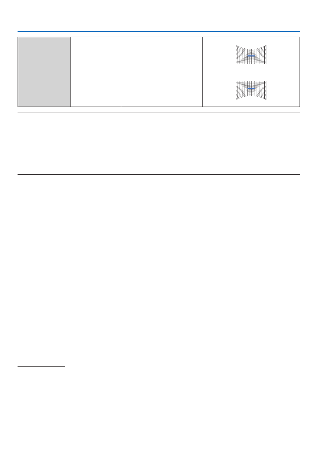
5. Using On-Screen Menu
Correct the horizontal line at the
bottom.
Press
▼
Extend the bottom horizontal
Curved cerrection Y Offset
line down while maintaining the
top area.
Correct the horizontal line at the
Press
top.
Expand the top horizontal line
Curved cerrection Y Offset
up while maintaining the bottom
area.
NOTE:
• After adjusting values about H/V keystone, if users adjust corner correction, values about H/V keystone will be reset. And after adjusting
values about Corner correction, if users adjust about H/V keystone, values about Corner correction will be reset also.
• Curved correction X offset and Curved correction Y offset can not be adjusted individually. Adjust Curved correction X offset and Curved
correction Y offset after adjusting the X/Y Curved correction.
• Maximum keystone range up to ±30° (PE506UL and PE506WL) and ±15° (PE456USL and PE456WSL) vertically and horizontally. However,
the image quality will deteriorate, and become more difficult to focus. install the projector with the minimal correction value.
• The screen size will be changed with various H/V keystone adjustments.
• Keystone may influence image aspect.
Grid image tune
Select this function to adjust the local points of the projected image.
1) Press ▲ ▼ ▶ ▶ button to select [Grid image tune] option.
2) Press the ENTER button.
Reset
Select this function to make adjustment value back to the factory default.
1) Press ▲ ▼ ▶ ▶ button to select [Reset] option.
2) Press the ENTER button.
• Release keystone mode.
[Security]
Set a PIN code to lock the usage of the projector to prevent unauthorized personnel from operating your projector.
Once the projector is on, the [PIN code] screen will be displayed.
1) Press ▲ ▼ button to select [Security] menu.
2) Press the ENTER button.
3) Press ▲ ▼ button to switch required item.
PIN code lock
This function helps preventing unauthorized personnel from changing projector setting.
Off......PIN code lock function is not available.
On......The [PIN code] screen will appear when the projector is on. If you want to change the PIN code lock or PIN
code (for three digits), you must enter the PIN code. The factory default PIN code is "111."
PIN code change
• You can change the PIN code. Click the ENTER button and select [PIN code change]. When the [PIN code] dialog
box is displayed, press the button to enter a valid PIN code, and select [Set] to display the [New PIN code]
dialog box. Set a new PIN code, confirm the contents in the dialog box, and select Set to set a new PIN code.
• The number you typed is displayed as “ * ”. To edit number you have entered, press the MENU button to move the
cursor to the number you want to change, press button to select the correct one.
• Repeat this step to type in a 3-digit number.
• Enter a three-digit number, move the cursor to [set]. Press the ENTER button, you can start to operate the projector.
• If the PIN code is invalid, the PIN code displayed as “ *** ” will be in red. Please try again with a valid one.
52
Page 71
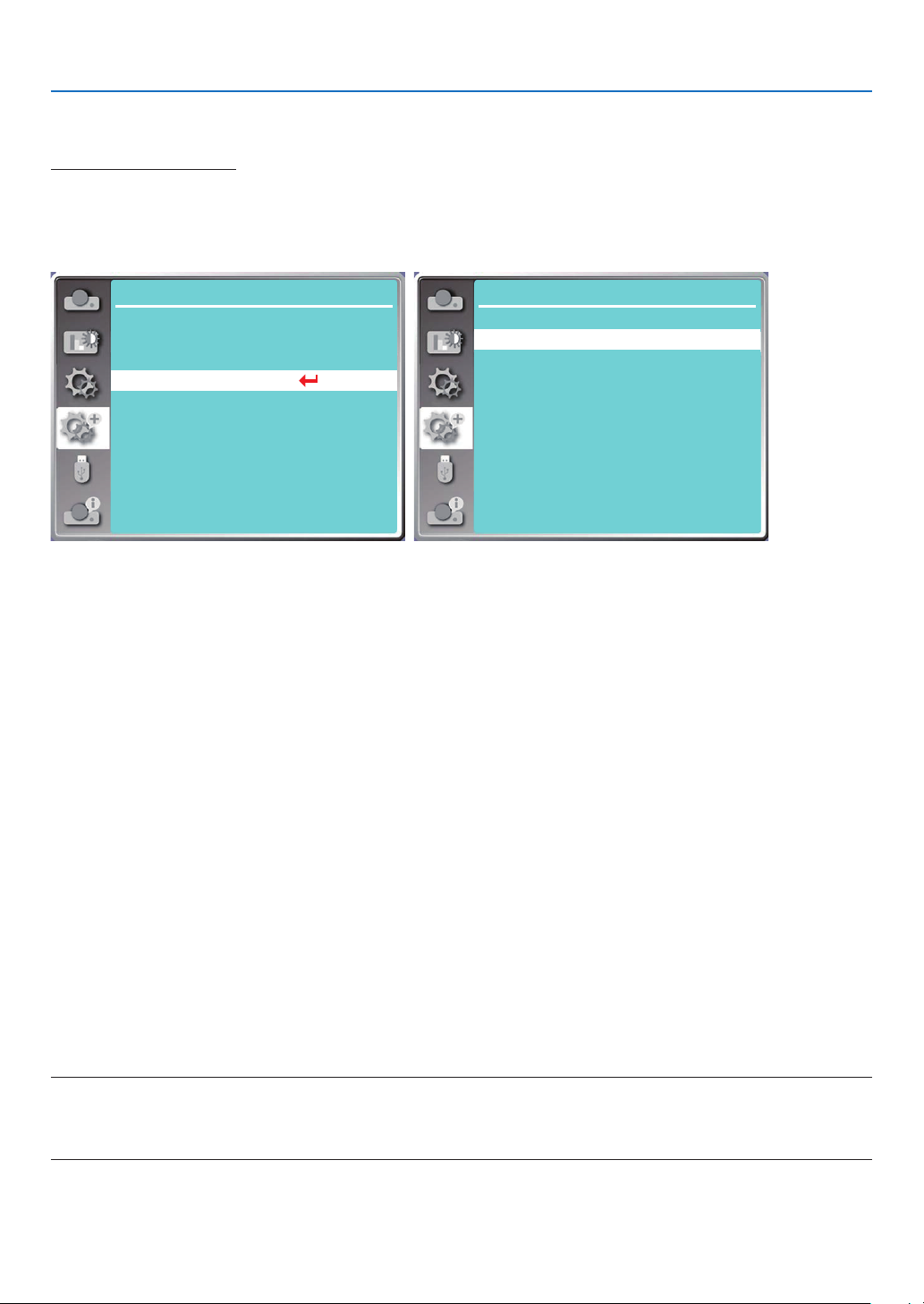
5. Using On-Screen Menu
• Please remember your new PIN code and keep it safe.
To cancel the PIN code
(1) While simultaneously pressing the POWER button and the ENTER button on the projector, plug the power cord
into the projector. After a while keep pressing the button, the PIN code input screen appears. Enter "111".
(2) Select On-Screen menu [Security] >> [PIN code lock] >> "On". As the input screen appears again, enter the
default value (111) and set the PIN code to "off" or set a new PIN code.
Expand
Language
Auto setup
Keystone
Security
Power management
Filter
Test pattern
Network setup
Control ID
Factory default
...
Expand
Security
OffPIN code lock
PIN code change
[Power management]
To reduce power consumption and maintain life cycle of light source, the power management function will turn off
the projection light source if your projector has no signals for a period of time.
1) Press ▲ ▼ button to select [Power management] menu.
2) Press the ENTER button.
3) Press ▲ ▼ button to switch required item.
Ready...... The power light indicator turns steady green when the light source is fully cooled down. The light source
turns on again if an input signal is connected or any button (except the power button) on the top control
panel or remote control is pressed during this period of time.
Shut down......The projector shut down after the light source is fully cooled down.
Off......Disable the power management function.
Timer...... Once the input signal is interrupted and no buttons has been pressed for 30 seconds afterwards, the “No
signal” message displays in the timer. The timer counts down until the light source turns off. Press arrow
button to set up the timer in range of 1~30 minutes.
Ready countdown...... Set the interval from the Ready mode change to the Standby mode (0 to 30 minutes) auto-
matically.
When it is set it to zero, the projector will never change automatically. Press the Power but-
ton to change your projector into the Standby mode and press any other button (except the
Power button) to power on.
NOTE:
• Factory default for standby time: 5 minutes. Count down for ready mode: 5 minutes.
• When selecting [Off], the [Timer] and [Ready countdown] is unavailable.
• When selecting [Shut down], the [Timer] is unavailable.
53
Page 72
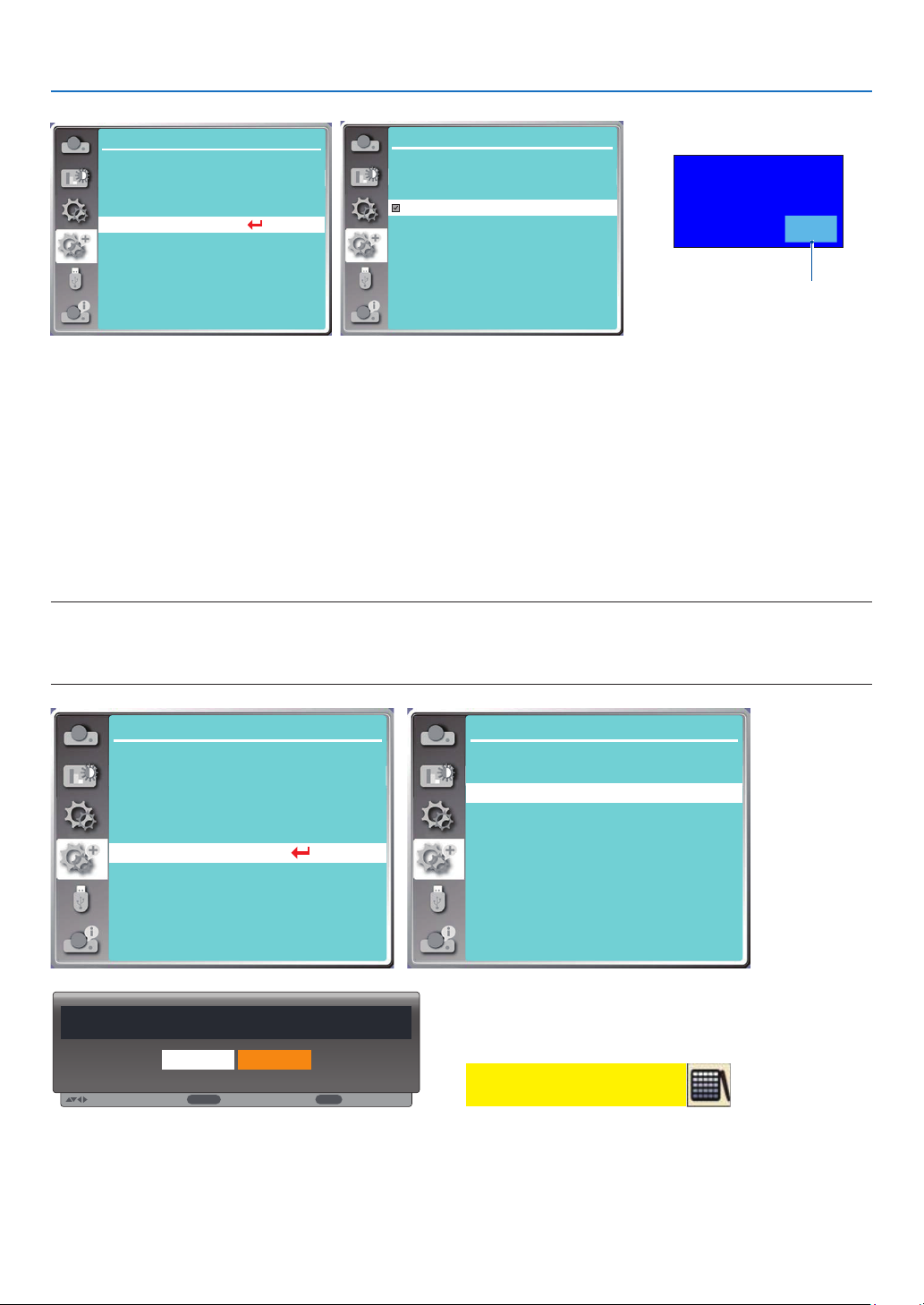
5. Using On-Screen Menu
:
ENTER
:
EXIT
:
Expand
Language
Auto setup
Keystone
Security
Power management
Filter
Test pattern
Network setup
Control ID
Factory default
...
Expand
Ready
Shut down
Off
Timer
Ready countdown
Power management
5 Min
5 Min
Remaining time before
power off the light source.
No signal
01: 20
[Filter]
Set this function to reset the filter usage time and set up warning display.
1) Press ▲ ▼ button to select [Filter] menu.
2) Press the ENTER button.
3) Press ▲ ▼ button to switch required item.
When the projector reaches the user-set cleaning time, filter warning icon will appear on the screen to notify the user
to clean the projector filter. Reset the filter counter after cleaning it and filter warning icon will be closed.
Filter counter......Displays the filter usage time.
Timer......Set the time to display a warning icon.
Filter counter reset......Reset filter counter.
NOTE:
• The screen will display the icon "Filter warning! Please change the filter! " when the projector has checks one warning. And the the warn-
ing icon will disappear 30 seconds later automatically, while only the Power button is effective during that period. The projector will give
warning again if the projector has checked filter block and will record the information.
Expand
Language
Auto setup
Keystone
Security
Power management
Filter
Test pattern
Network setup
Control ID
Factory default
...
Expand
Filter counter
Timer
Filter counter reset
Filter counter reset?
Yes No
Move
Select
Back
[Test pattern]
Select this function to display the projector's built-in test pattern.
1) Press ▲ ▼ button to select [Test pattern] menu.
2) Press the ENTER button.
3) Press ▲ ▼ button to switch required item.
Filter
5H
1000H
Filter warning
54
Page 73
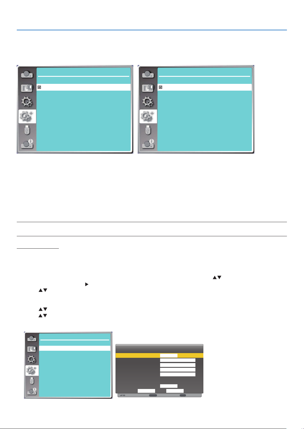
5. Using On-Screen Menu
:
:
ENTER
:
EXIT
4) Press the ENTER button.
Off / Gray scale 1 / Gray scale 2 / Gray scale 3 / Gray scale 4 / Color bar / Red / Green / Blue / Cross hatch /
White / Black / Raster gray: Use the On-Screen menu to display the test pattern.
Expand
Off
Gray scale1
Gray scale2
Gray scale3
Gray scale4
Color bar
Red
Green
Blue
Cross hatch
Test pattern 1/2
Expand
White
Black
Raster gray
Test pattern
2/2
[Network setup]
Function: This function is designed to allow the computer control the projector remotely via network.
1.Required equipment: Projector, computer, network cable
2. Connection:
Connect the projector to the router or switch in the LAN with a straight or crossover network cable. If you connect
the projector and the computer directly, you cannot connect with a straight-through network cable. It is recommended to use a crossover network cable.
3.Turn on the computer. The LAN port on computer and projector are flashing after turn on the projector.
NOTE:
• It is recommended that users use a Category 5 or higher LAN cable.
Operation steps
1. Turn on your projector.
2. Acquire the IP address, with DHCP set to on and auto IP allocation set to On. (You may set DHCP to Off and set
up IP address manually if you are somehow familiar with networking.)
3. Enter the network setup menu.
(1) Press the MENU button on remote control or the top control panel, press button to select [Expand]
icon. Press the ENTER or button.
(2) Press button select [Network setup] and press the ENTER button to enter.
MAC address......Display the MAC address of wired LAN.
IP address...........Display the IP address of wired LAN.
(3) Press button select [Network setting] and press the ENTER button to enter.
(4) Press button to set DHCP "On" to obtain an IP address, Subnet, Gateway and DNS automatically, and press
the ENTER button to confirm.
Expand
Network setting
Network information
MAC address:
IP address
Network Setup
7C:6F:F8:4E:B9:2F
192.168.1.100
Wired LAN
Wireless LAN
Move
DHCP
IP address
Subnet
Gateway
DNS
Setting
Next
On
. . .
. . .
. . .
. . .
On
CancelSet
Back
55
Page 74
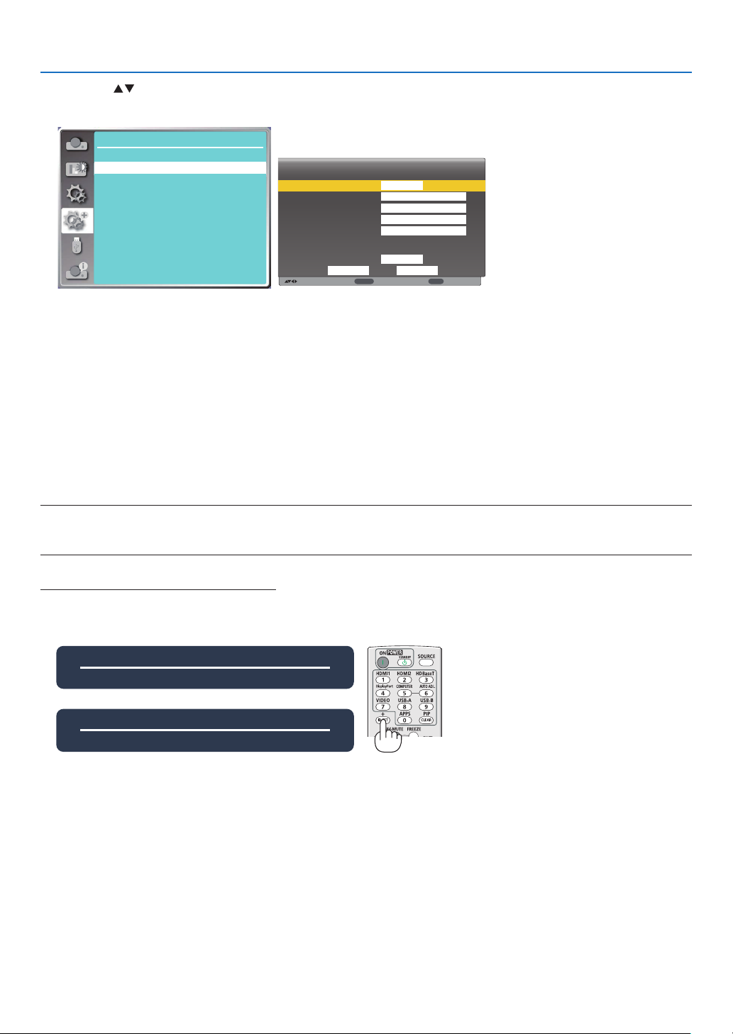
5. Using On-Screen Menu
:
:
:
ENTER
EXIT
Press the button to set DHCP "Off", then press the ENTER button to enter an IP address, then press ▼ button
to select Subnet , Gateway and DNS manually. And press the ENTER button to confirm.
Expand
Network setting
Network information
MAC address:
IP address
Network Setup
7C:6F:F8:4E:B9:2F
192.168.1.100
Wired LAN
Wireless LAN
Move
DHCP
IP address
Subnet
Gateway
DNS
Setting
off
192 . 168 . 1 . 1
255 . 255 . 255 . 0
192 . 168 . 1 . 1
0 . 0 . 0 . 0
On
CancelSet
Next
Back
[Control ID]
Select this function to operate multiple projectors separately and independently with the single remote control that
has the [Control ID] function. If you assign the same ID to all the projectors, you can conveniently operate all the
projectors together using the single remote control. To do so, you have to assign an ID number to each projector.
1) Press ▲ ▼ button to select [Control ID] menu.
2) Press the ENTER button.
3) Press ▲ ▼ button to switch required item.
4) Press the ENTER button.
Control ID......Select [Off] to turn off the [Control ID] setting and select [On] to turn on the [Control ID] setting.
Control ID Number......Select a number from 1 to 254 you wish to assign to your projector.
NOTE:
• When [On] is selected for [Control ID], the projector cannot be operated by using the remote control that does not support the Control ID
function. (In this case the buttons on the projector cabinet can be used.)
Assigning or Changing the Control ID
1. Turn on the projector.
2. Press the ID SET button on the remote control.
The Control ID screen will be displayed.
Control ID(Inactive)
Control ID Number 5
Control ID(Active)
Control ID Number 5
If the projector can be operated with the current remote control ID, the [Active] will be displayed. If the projector
cannot be operated with the current remote control ID, the [Inactive] will be displayed. To operate the inactive
projector, assign the control ID used for the projector by using the following procedure (Step 3).
3. Press one of numeric keypad buttons while pressing and holding the ID SET button on the remote control.
Example:
To assign “3”, press the “3” button on the remote control.
No ID means that all the projectors can be operated together with a single remote control. To set “No ID”, enter
“000” or press the CLEAR button.
TIP: The range of IDs is from 1 to 254.
4. Release the ID SET button.
The updated Control ID screen will be displayed.
56
Page 75
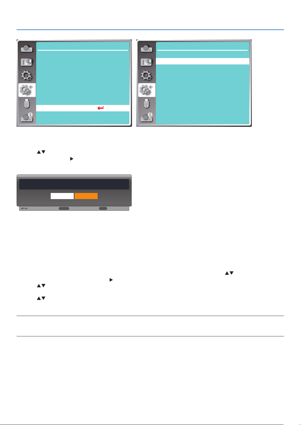
5. Using On-Screen Menu
:
:
ENTER
:
EXIT
Expand
Language
Auto setup
Keystone
Security
Power management
Filter
Test pattern
Network setup
Control ID
Factory default
...
Expand
Control ID
Control ID Number
[Factory default]
This function resets all your settings to factory default.
1) Press button to select [Factory default] menu.
2) Press the ENTER or button.
3) Press button to select "Yes", then press the ENTER button.
Return to factory default?
Yes No
Move
Select
Back
Control ID
Off
1
❽ Menu Descriptions & Functions [USB-A]
The projector has expand function, you can select other functions as described below.
When the USB memory inset into the projector, the USB-A function can project pictures stored in the USB
memory.
Press the MENU button on the remote control to display the On-Screen menu. Press the button to select the
USB-A menu, then press the ENTER or button.
1) Press button to select required item.
2) Press the ENTER button.
3) Press button to set options.
4) Press the ENTER button.
NOTE:
• When selecting [USB-A] as input signal, the "USB-A" menu is available.
• In addition to "Set slide" menu, even change the settings, If you do not implement the [Apply], the setting value of the change is invalid.
57
Page 76
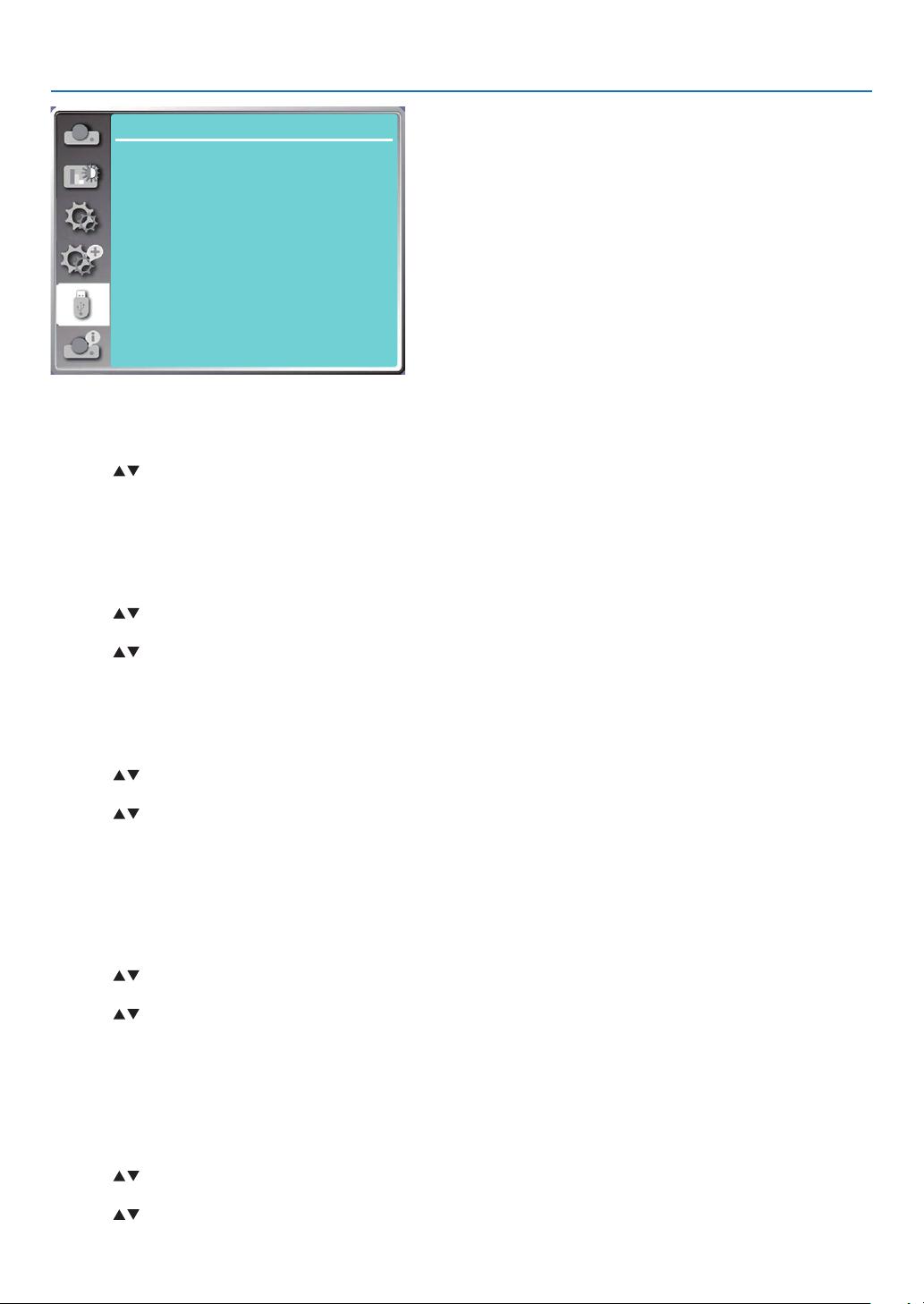
USB-A
Set slide
Slide transition effect
Sort order
Rotate
Best fit
Repeat
Apply
Slide right
Name order
No rotate
Off
On
[Set slide]
Select this function to play slides.
1) Press button to select a file.
2) Press button to select [Set slide] menu.
3) Press the ENTER or button.
• Full screen display
• Press the ENTER to return to the thumbnail.
[Slide transition effect]
Select this function to set the slide's playback, when switching slides.
1) Press button to select [Slide transition effect] menu.
2) Press the ENTER or button.
3) Press button to switch required item.
Slide down.....Switch slides from top to bottom .
Slide right...... Switch slides from left to the right.
5. Using On-Screen Menu
[Sort order]
Select this function to set the slide's order.
1) Press button to select [Sort order] menu.
2) Press the ENTER button.
3) Press button to switch required item.
Extend order...... Sort by extend names of file or folder.
Size order...........Sort by size of file or folder.
Time order..........Sort by the time of file or folder.
Name order........ Sort by names of file or folder.
[Rotate]
Set the rotation direction of images.
1) Press button to select [Rotate] menu.
2) Press the ENTER button.
3) Press button to switch required item.
No rotate ........Rotation is invalid.
270 degree......Rotate clockwise by 270 degrees.
180 degree......Rotate clockwise by 180 degrees.
90 degree........Rotate clockwise by 90 degrees.
[Best fit]
Set the image to be compatible with projection screen.
1) Press button to select [Best fit] menu.
2) Press the ENTER button.
3) Press button to switch required item.
On.....Display image by the aspect ratio of the screen.
58
Page 77

Off.....Display image by the normal pixels.
[Repeat]
Select this function to play images repeatedly.
1) Press button to select [Repeat] menu.
2) Press the ENTER or button.
3) Press button to switch required item.
On.....Replay the first image, after playing the last one.
Off.....Return to the thumbnail display screen, after playing the last image.
[Apply]
Only be used in playing slides.
1) Press button to select [Apply] menu.
2) Press the ENTER or button.
5. Using On-Screen Menu
59
Page 78
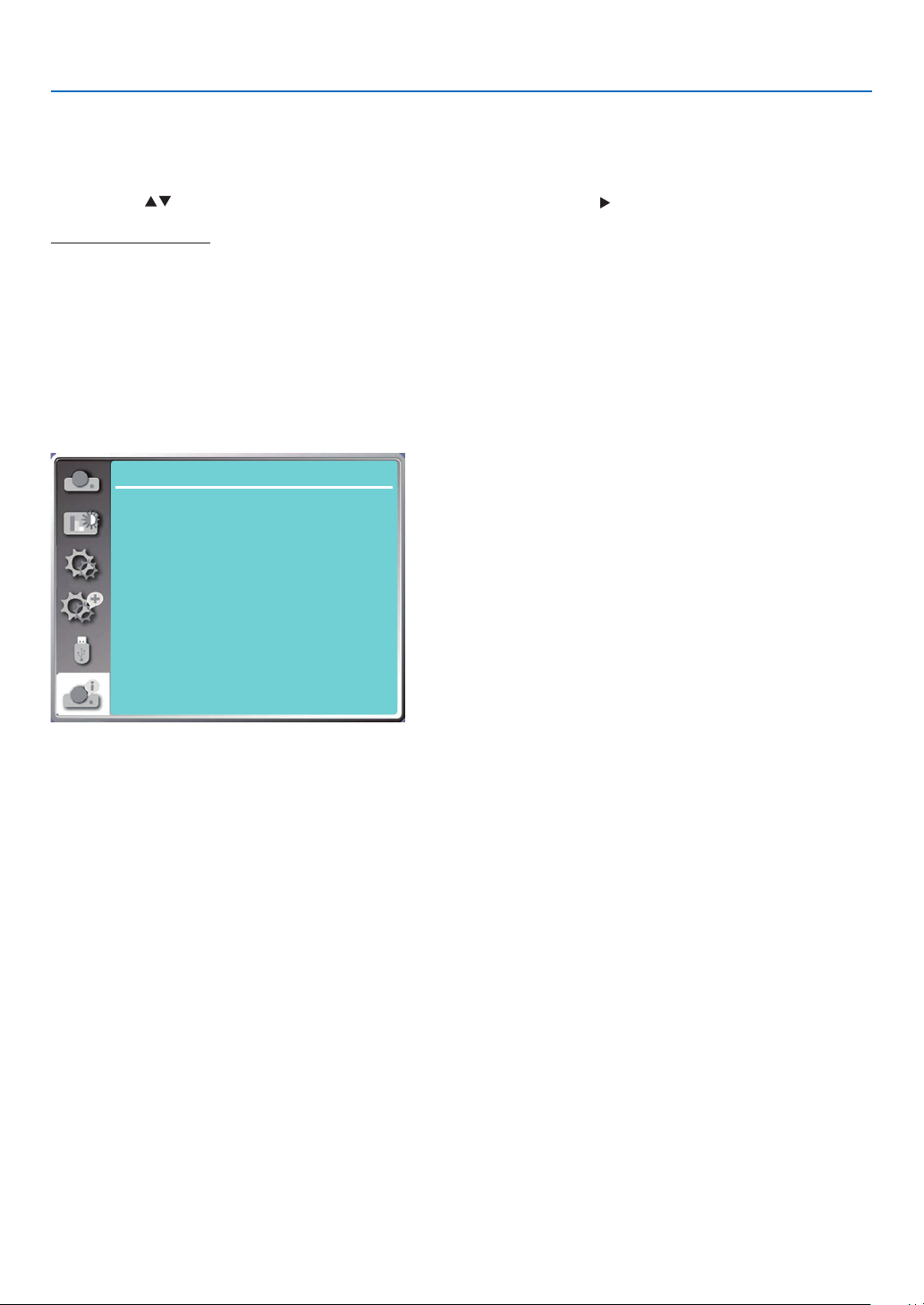
5. Using On-Screen Menu
❾ Menu Descriptions & Functions [Info.]
Select Info. function to detect the projected image signal and the projector operating status.
Press the HELP button on the remote control or the MENU button on the control panel to display the On-Screen
menu. Press button to select the [Info. ] menu, then press the ENTER or button.
Info. display as follows:
Input......Display selected input source.
H- sync freq.......Display H- sync freq. of input signal in unit of KHz. Show “---KHz” when no signals are in existence.
V- sync freq.......Display V- sync freq. of input signal in unit of KHz. Show “---Hz” when no signals are in existence.
Light counter......Display the light's usage time and remaining time in percentage .
Model name......Display the projector's model name.
S/N......Display the projector's serial number.
Firmware version......Display the projector's firmware version.
SUBCPU......Display the projector's SUBCPU's Version.
Info.
Input
H-sync freq.
V-sync freq.
Laser counter
Model name
S/N
Firmware version
SUBCPU
Computer
...
31.50 kHZ
59.99 HZ
30 H
99.85%
xxxxx
xxxxx
1.00.010
0.10
60
Page 79
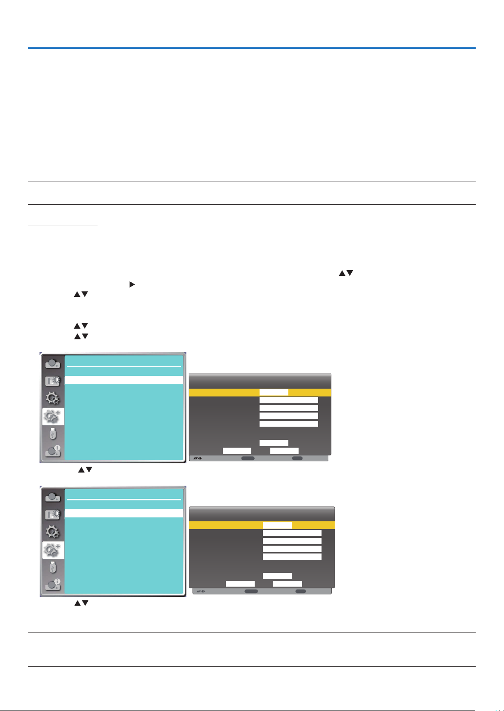
6. Network control
:
:
:
ENTER
EXIT
:
:
ENTER
:
EXIT
❶ Network control operation
Function: This function is designed to remote control the projector from your computer in the same LAN.
Preparation
1. Required equipment: Projector, Computer, Network cable
2. Connection:
Connect the projector to the router or switch in the LAN with a straight or crossover network cable. If you connect
the projector and the computer directly, you cannot connect with a straight-through network cable.
It is recommended to use a crossover network cable.
3. Turn on the computer. The LAN port on computer and projector are flashing after turn on the projector.
NOTE:
• It is recommended that users use a Category 5 or higher LAN cable.
Operation steps
1. Turn on your projector.
2. Acquire the IP address, with DHCP set to "On" and auto IP allocation set to on. (You may set DHCP to "Off" and
set up IP address manually if you are somehow familiar with networking.)
3. Enter the network setup menu.
(1) Press the MENU button on remote control or the top control panel, press button to select [Expand] icon.
Press the ENTER or button.
(2) Press button select [Network setup] and press the ENTER button to enter.
MAC address......Display the MAC address of wired LAN.
IP address...........Display the IP address of wired LAN.
(3) Press button select [Network setting] and press the ENTER button to enter.
(4) Press button to set DHCP "On" to obtain an IP address, Subnet , Gateway and DNS automatically, and
press the ENTER button to confirm.
Expand
Network setting
Network information
MAC address:
IP address
Press the button to set DHCP "Off", then press the ENTER button to enter an IP address, then press ▼ button
to enter Subnet , Gateway and DNS manually. And press the ENTER button to confirm.
Expand
Network setting
Network information
MAC address:
IP address
(5) Press button to select [Set], press the ENTER button to wait until the “Please wait.” message disappears.
Network Setup
Network Setup
7C:6F:F8:4E:B9:2F
192.168.1.100
7C:6F:F8:4E:B9:2F
192.168.1.100
Wired LAN
Wireless LAN
Move
Wired LAN
Wireless LAN
Move
DHCP
IP address
Subnet
Gateway
DNS
Setting
DHCP
IP address
Subnet
Gateway
DNS
Setting
off
192 . 168 . 1 . 1
255 . 255 . 255 . 0
192 . 168 . 1 . 1
0 . 0 . 0 . 0
On
CancelSet
Next
On
. . .
. . .
. . .
. . .
On
Next
Back
CancelSet
Back
NOTE:
• If you are using the wireless LAN connection, please check the SSID / ESSID and wireless IP address in the network setting status, and
write down the information.
61
Page 80
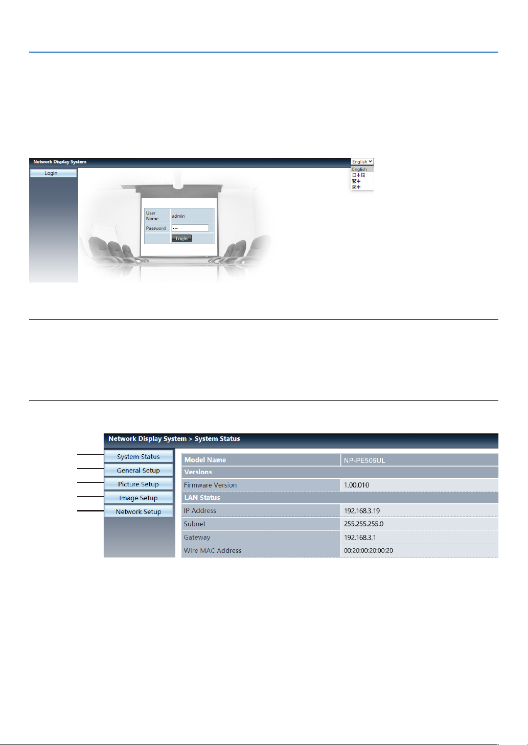
6. Network control
❷ Enter through a Web browser
Connecting Your Computer
1) Start the computer's Web browser.
2) Enter the IP address on the projector set in the URL input field of the Web browser. The "Network Display System"
window for your projector will be displayed.
3) Click [Login] at the top left of the window.
4) Enter the password in the [Password], then click [Login]
"* " the factory default setting is the user name: "admin" (administrator privileges), password: "admin".
NOTE:
• Users can click on the top right corner of the Web browser screen to select the display language and available languages are English,
Japanese, Traditional Chinese, Simplified Chinese.
• Do not start multiple Web browser settings or control. Do not use more than one computer set or control the projector.
• Please change your password.
• If the network does not appear on screen controls, please consult your network administrator.
• Please refresh the web page before operating the projector.
Description of each option
①
②
③
④
⑤
① System status: Click this option to display the [System status] page.
② General setup: Click this option to display the [General setup] page.
③ Picture setup: Click this option to display the [Picture setup] page.
④ Image setup: Click this option to display the [Image setup] page.
⑤ Network setup: Click this option to display [Network setup] page.
62
Page 81
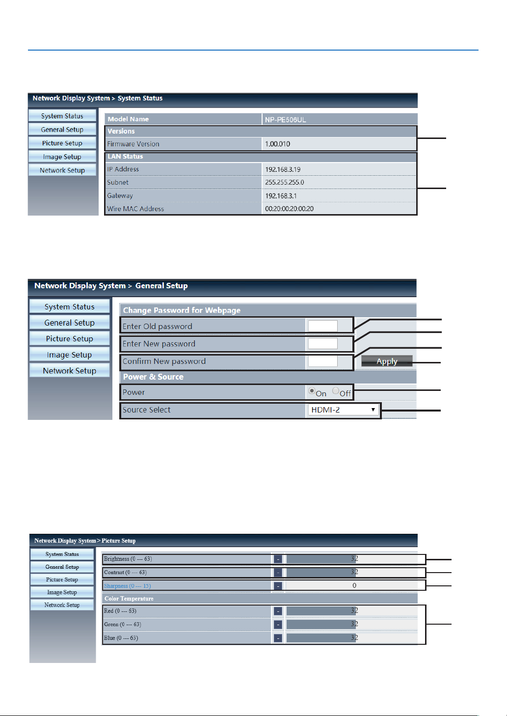
❸ [System status] page
① Versions: Displays the firmware version of the projector.
② LAN status: Displays the LAN connection status.
4 [General setup] page
6. Network control
①
②
①
②
③
④
① Enter old password: Enter the password for the configuration.
② Enter new password: Enter a new password.
③ Confirm new password: Re-enter the new password to confirm.
④ Apply: Update settings.
⑤ Power: Switch on the power of the projector on / off.
⑥ Source select: Switch the input source of the projector.
❺ [Picture setup] page
⑤
⑥
①
②
③
④
63
Page 82
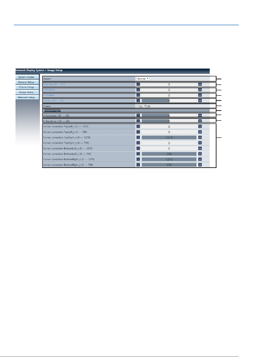
① Brightness:Adjust the brightness of the projected image.
② Contrast:Adjust the contrast of the projected image.
③ Sharpness:Adjust the sharpness of the projected image.
④ Color Temperature:Adjust the color temperature of the projected image.
❻ [Image setup] page
6. Network control
①
②
③
④
⑤
⑥
⑦
⑧
⑨
⑩
① Aspect: Switch the aspect ratio of the projected image.
② Fine sync: Adjust the phase of the projected image.
③ H position: Adjust the horizontal position of the projected image.
④ V position: Adjust the vertical position of the projected image.
⑤ H. size: Adjust the horizontal dimension of the projected image.
⑥ Freeze: Select the function to switch the screen freeze on and off.
⑦ Auto PC adj.: Implement the automatic computer adjustment function.
⑧ V keystone: Correct trapezoidal distortion in vertical direction.
⑨ H keystone: Correct horizontal distortion in horizontal direction.
⑩ Corner correction: Correct four angles of the projected image.
64
Page 83
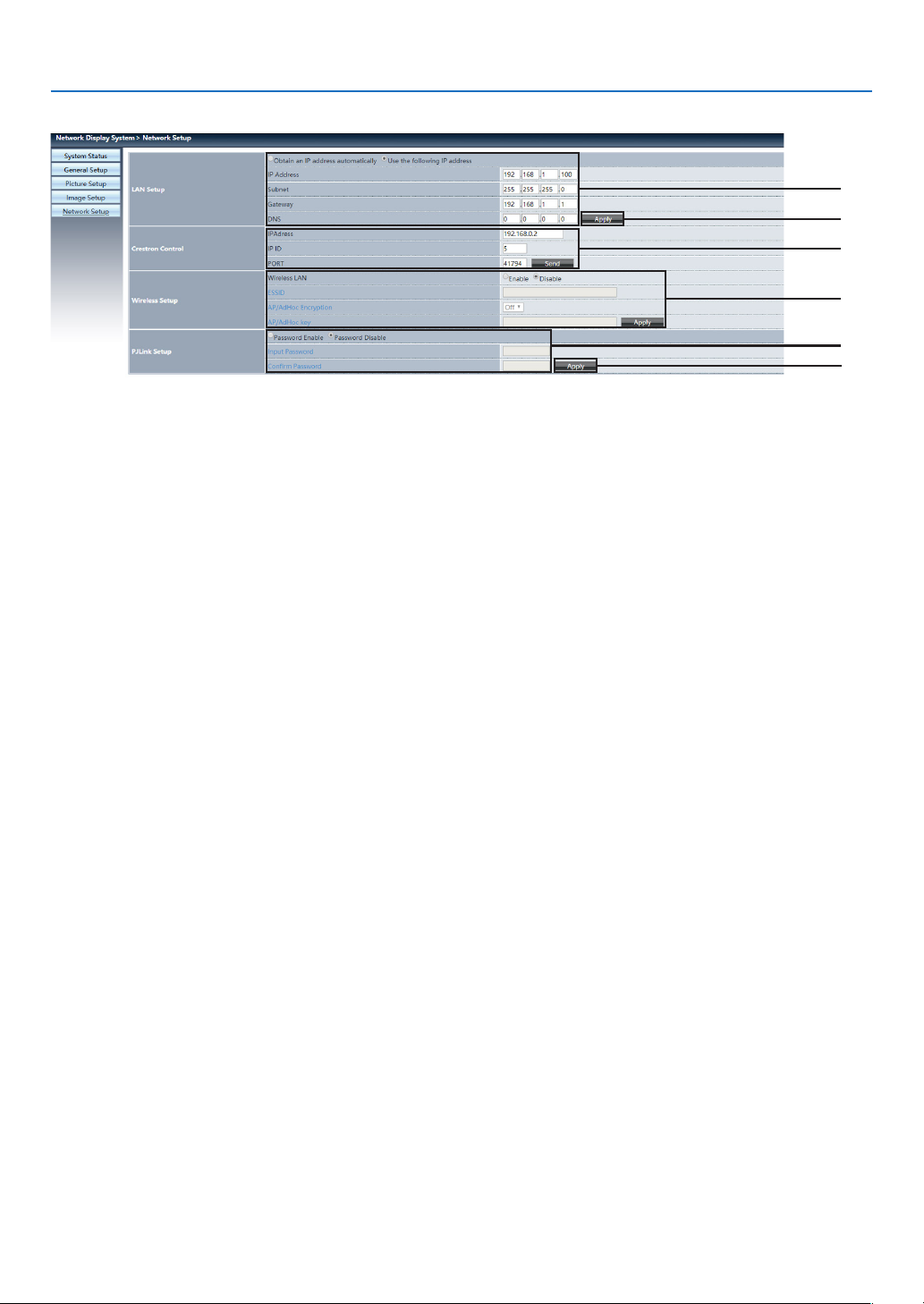
❼ [Network setup] page
① Network setup
If you want to enable the DHCP client, select the IP address automatically.
IP address:
Please enter the IP address when you do not use the DHCP server.
Subnet :
Please enter a subnet shield when you do not use the DHCP server .
Gateway:
Please enter the gateway when you do not use the DHCP server.
6. Network control
①
②
③
④
⑤
②
DNS:
Please enter the DNS address, when you do not use the DHCP server.
Available character : digital (0 - 9), a period (.)
(For example: 192.168.0.253)
② Apply
Update settings.
③ Crestron control
Connect Crestron tool by setting IP address, IP ID and PORT options.
④ Wireless Setup
Wireless LAN: Please select wireless LAN on or off.
ESSID: Please enter the ESSID.
AP/AdHoc Encryption: Please select password set on or off.
AP/AdHoc key: Please set password.
⑤
PJLink setup
Input password: Input the PJLink password.
Confirm password: Input the PJLink password once again and confirm.
65
Page 84
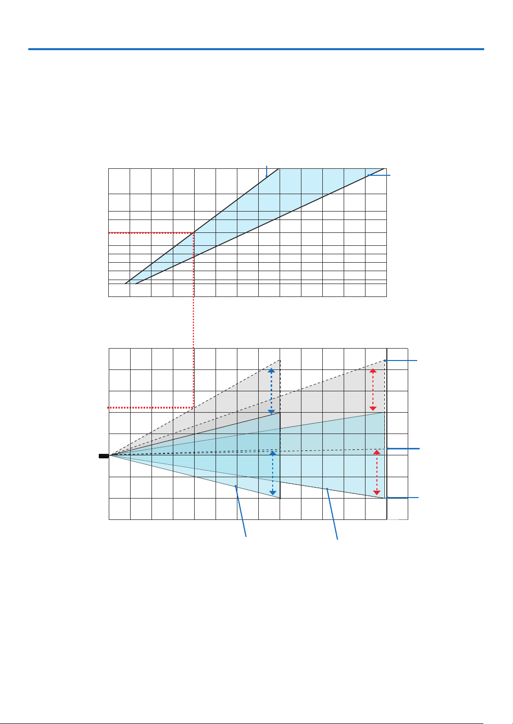
7. Installation and Connections
100
120
180
200
300
❶ Setting Up the Screen and the Projector
Use this to get a general idea of what the screen size will be when set in a certain position, what size screen you will
need, and what distance you will need to project images of the desired size.
[PE506UL]
The projection distance range at which focusing is possible is 0.77 m (for 30 inches) to 12.89 m (for 300 inches).
Install within this range.
(inch)
240
150
80
Screen size
60
40
30
0123 56789 10 11 12 13
(m)
5
4
3
2
1
0
projector lens
-1
-2
Screen height from the center of the
-3
123456789
4
When zoom lever turned to wide
[Projection distance]
10 11
12 13
When zoom
lever turned to
telescopic
(m)
14
(m)
The top of the screen
when the lens shift is
the largest
Projector lens center
and screen center
The bottom edge
of the screen at the
minimum lens shift
When the zoom lever is turned wide When the zoom lever is turned to telescopic
* The figures indicated for “height of screen from projector lens center” on the projection distance table are for a
lens shift of 60% V.
Reading the Table
From the upper table on this page, to project wide images on a 150 inch screen, install at about 4.0 m from the front.
Also, from the lower table we can see that about 2.2 m are required from the projector’s lens center to the upper
edge of the screen. Use this to see whether or not enough height can be provided from the projector to the ceiling
and for installing the screen. The diagram shows the projection distance when the projector is installed horizontally.
The projected image can be moved up and down, left and right using the lens shift function. (→ page 19 )
66
Page 85
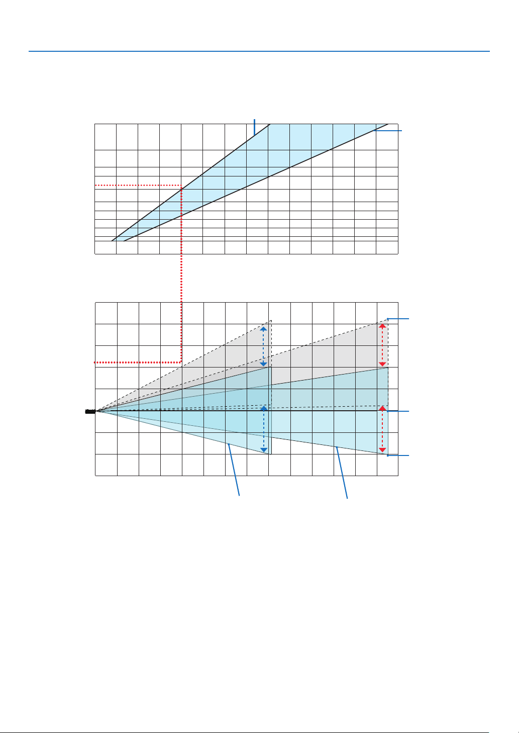
7. Installation and Connections
[PE506WL]
The projection distance range at which focusing is possible is 0.78 m (for 30 inches) to 13.55 m (for 300 inches).
Install within this range.
(inch)
300
240
0
0
150
0
0
80
Screen size
60
40
30
012345 7 8 9 10 11 12 13 146
(m)
5
4
3
2
1
0
lens
-1
When zoom lever turned to wide
When zoom
lever turned to
telescopic
(m)
[Projection distance]
The top of the screen
when the lens shift is
the largest
Projector lens center
and screen center
-2
The bottom edge
of the screen at the
-3
Screen height from the center of the projector
123456789
When the zoom lever is turned wide
10 11
12 13
When the zoom lever is turned to telescopic
minimum lens shift
(m)
14
* The figures indicated for “height of screen from projector lens center” on the projection distance table are for a
lens shift of 55% V.
Reading the Table
From the upper table on this page, to project wide images on a 150 inch screen, install at about 4.0 m from the front.
Also, from the lower table we can see that about 2.1 m are required from the projector’s lens center to the upper
edge of the screen. Use this to see whether or not enough height can be provided from the projector to the ceiling
and for installing the screen. The diagram shows the projection distance when the projector is installed horizontally.
The projected image can be moved up and down, left and right using the lens shift function. (→ page 19 )
67
Page 86
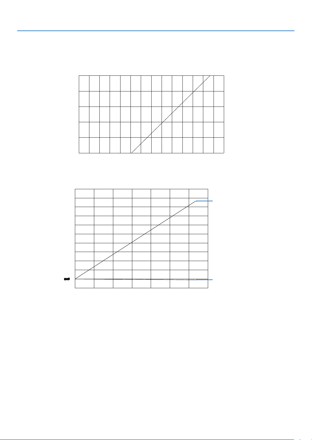
7. Installation and Connections
[PE456USL/PE456WSL]
The projection distance range at which focusing is possible is 0.517 m (for 55 inches) to 1.268 m (for 130 inches).
Install within this range.
(inch)
Screen size
[Projection distance]
(m)
Screen height from the center of the projector lens
[Projection distance]
(m)
The Top of Screen
The bottom of Screen
(m)
Reading the Table
From the upper table on this page, to project wide images on a 80 inch screen, install at about 0.768 m from the front.
Also, from the lower table we can see that about 1.066 m are required from the projector’s lens center to the upper
edge of the screen. Use this to see whether or not enough height can be provided from the projector to the ceiling
and for installing the screen. The diagram shows the projection distance when the projector is installed horizontally.
68
Page 87
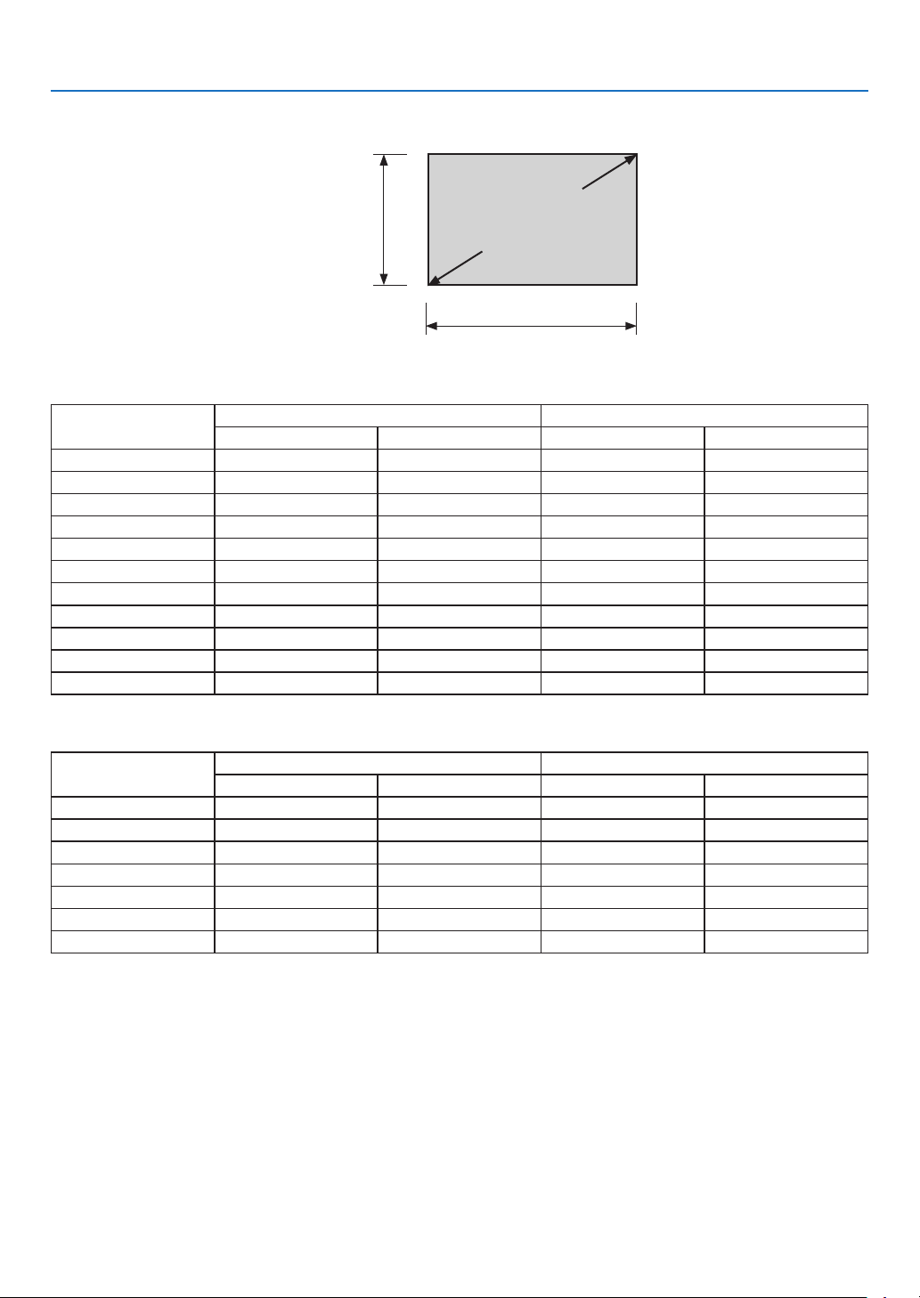
Tables of screen sizes and dimensions
7. Installation and Connections
[PE506UL/PE506WL]
Size (inches)
30 64.6 25.4 40.4 15.9
40 86.2 33.9 53.8 21.2
50 107.7 42.4 67.3 26.5
60 129.2 50.9 80.8 31.8
80 172.3 67.8 107.7 42.4
100 215.4 84.8 134.6 53.0
120 258.5 101.8 161.5 63.6
150 323.1 127.2 201.9 79.5
200 430.8 169.6 269.2 106.0
250 538.5 212.0 336.5 132.5
300 646.2 254.4 403.9 159.0
Screen height
Screen size
(diagonal)
Screen width
Screen width Screen height
(cm) (inches) (cm) (inches)
[PE456USL/PE456WSL]
Size (inches)
55 118.5 46.6 74.0 29.1
60 129.2 50.9 80.8 31.8
70 150.8 59.4 94.2 37.1
80 172.3 67.8 107.7 42.4
90 193.9 76.3 121.2 47.7
100 215.4 84.8 134.6 53.0
130 280.0 110.2 175.0 68.9
Screen width Screen height
(cm) (inches) (cm) (inches)
69
Page 88
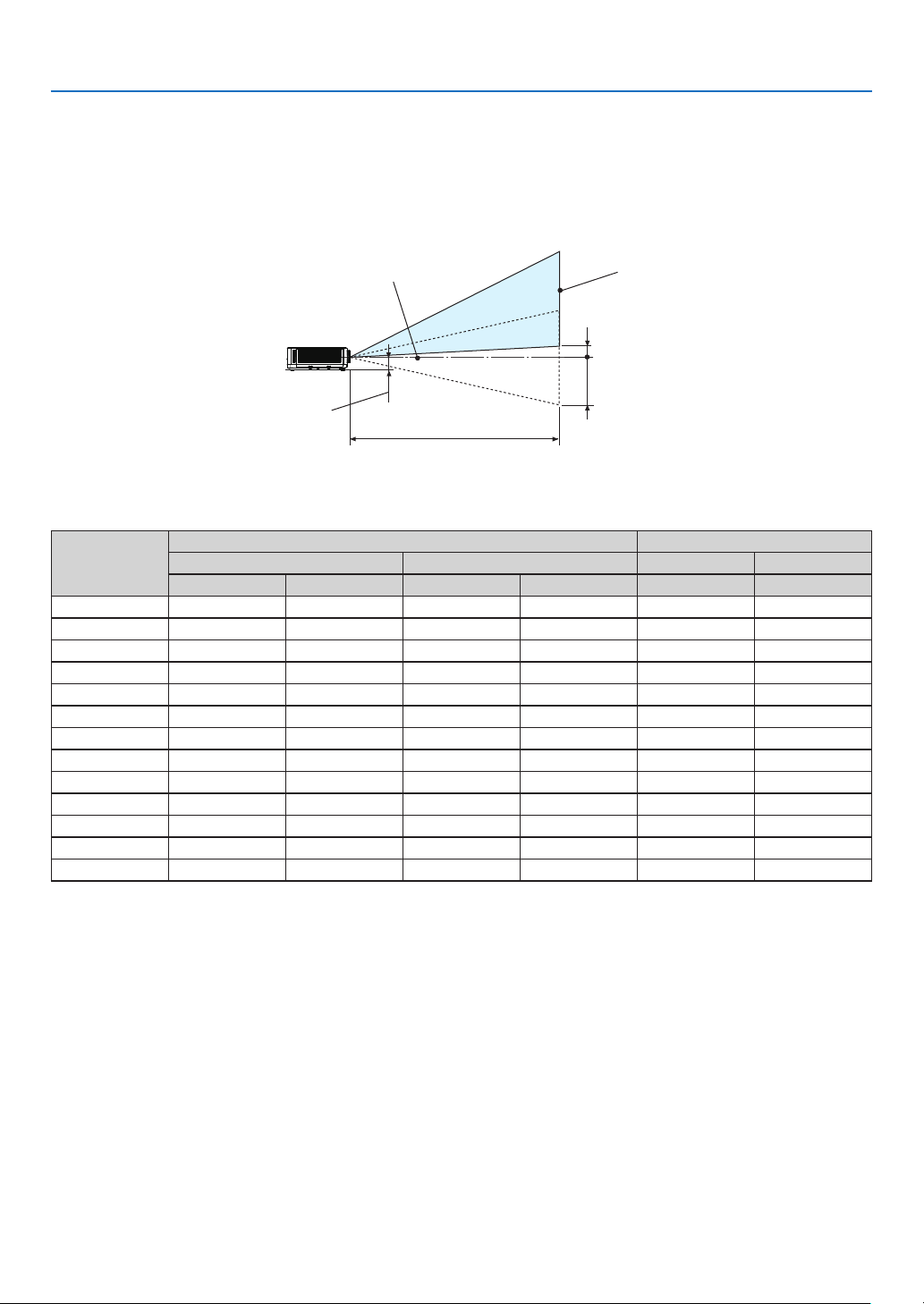
7. Installation and Connections
Example of installation on a desktop
The diagram below shows an example of when the projector is used on a desktop.
Horizontal projection position: Equal distance to the left and right from the center of the lens vertical projection
position: (see table below)
[PE506UL]
Lens center
Approximately 82 mm
Projection distance L
Screen surface
Measurement +H
Measurement −H
(NOTE) Height from lens center to lower edge of screen (with tilt feet screwed in)
Screen size
(inches)
(m) (inches) (cm) (inches)
Wide Tele Wide Tele 0%V – 60%V 0%V – 60%V
Throw distance L Height H
30 0.77 1.26 30.1 49.5 −20.2 – +4.0 −7.9 – +1.6
40 1.03 1.69 40.6 66.5 −26.9 – +5.4 −10.6 – +2.1
60 1.56 2.55 61.6 100.4 −40.4 – +8.1 −15.9 – +3.2
80 2.10 3.41 82.6 134.3 −53.8 – +10.8 −21.2 – +4.2
90 2.36 3.84 93.1 151.3 −60.6 – +12.1 −23.8 – +4.8
100 2.63 4.27 103.6 168.2 −67.3 – +13.5 −26.5 – +5.3
120 3.16 5.13 124.6 202.1 −80.8 – +16.2 −31.8 – +6.4
150 3.96 6.43 156.1 253.0 −101.0 – +20.2 −39.7 – +7.9
180 4.76 7.72 187.6 303.8 −121.2 – +24.2 −47.7 – +9.5
200 5.30 8.58 208.6 337.8 −134.6 – +26.9 −53.0 – +10.6
250 6.36 10.30 250.5 405.6 −161.5 – +32.3 −63.6 – +12.7
270 7.16 11.59 282.0 456.4 −181.7 – +36.3 −71.5 – +14.3
300 7.96 12.89 313.5 507.3 −201.9 – +40.4 −79.5 – +15.9
70
Page 89
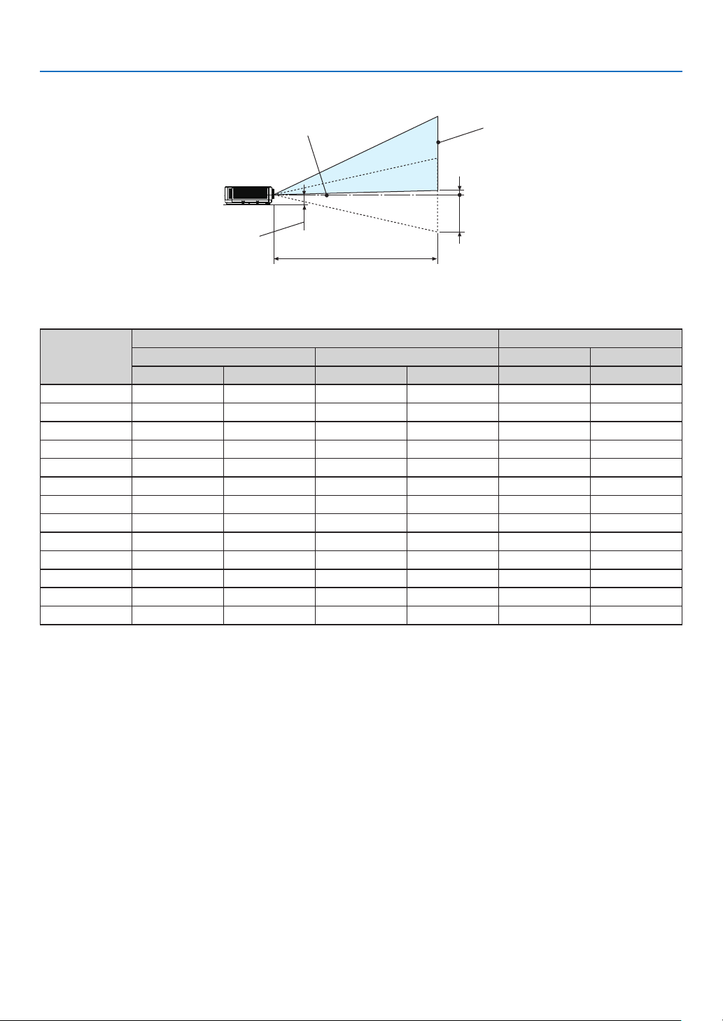
[PE506WL]
7. Installation and Connections
Lens center
Approximately 82 mm
Projection distance L
Screen surface
Measurement +H
Measurement −H
(NOTE) Height from lens center to lower edge of screen (with tilt feet screwed in)
Screen size
(inches)
(m) (inches) (cm) (inches)
Wide Tele Wide Tele 0%V – 55 %V 0%V – 55%V
Throw distance L Height H
30 0.78 1.32 41.4 52.0 –20.2 – +2.0 –7.9 – +0.8
40 1.05 1.77 41.4 69.8 –26.9 – +2.7 –10.6 – +1.1
60 1.60 2.68 62.9 105.5 –40.4 – +4.0 –15.9 – +1.6
80 2.14 3.59 84.4 141.1 –53.8 – +5.4 –21.2 – +2.1
90 2.42 4.04 95.2 159.0 –60.6 – +6.1 –23.8 – +2.4
100 2.69 4.49 105.9 176.8 –67.3 – +6.7 –26.5 – +2.6
120 3.24 5.40 127.4 212.5 –80.8 – +8.1 –31.8 – +3.2
150 4.06 6.76 159.6 266.0 –101.0 – +10.1 –39.7 – +4.0
180 4.87 8.12 191.9 319.5 –121.2 – +12.1 –47.7 – +4.8
200 5.42 9.02 213.4 355.2 –134.6 – +13.5 –53.0 – +5.3
250 6.51 10.83 256.3 426.5 –161.5 – +16.2 –63.6 – +6.4
270 7.33 12.19 288.6 426.5 –181.7 – +18.2 –71.5 – +7.2
300 8.15 13.55 320.8 533.5 –201.9 – +20.2 –79.5 – +7.9
71
Page 90
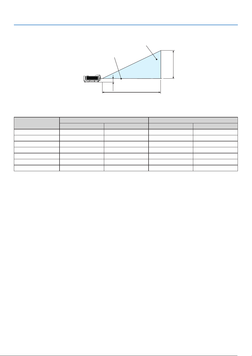
7. Installation and Connections
[PE456USL/PE456WSL]
Screen surface
Lens center
Approximately 82 mm
Projection distance L
(NOTE) Height from lens center to lower edge of screen (with tilt feet screwed in)
Height H
Screen size
(inches)
Throw distance L Height H
(m) (inches) (cm) (inches)
55 0.52 20.37 74.04 29.15
60 0.57 22.34 80.77 31.80
70
0.67 26.28 94.23 37.10
80 0.77 30.22 107.70 42.40
90 0.87 34.16 121.16 47.70
100 0.97 38.09 134.62 53.00
130 1.27 49.91 175.01 68.90
72
Page 91
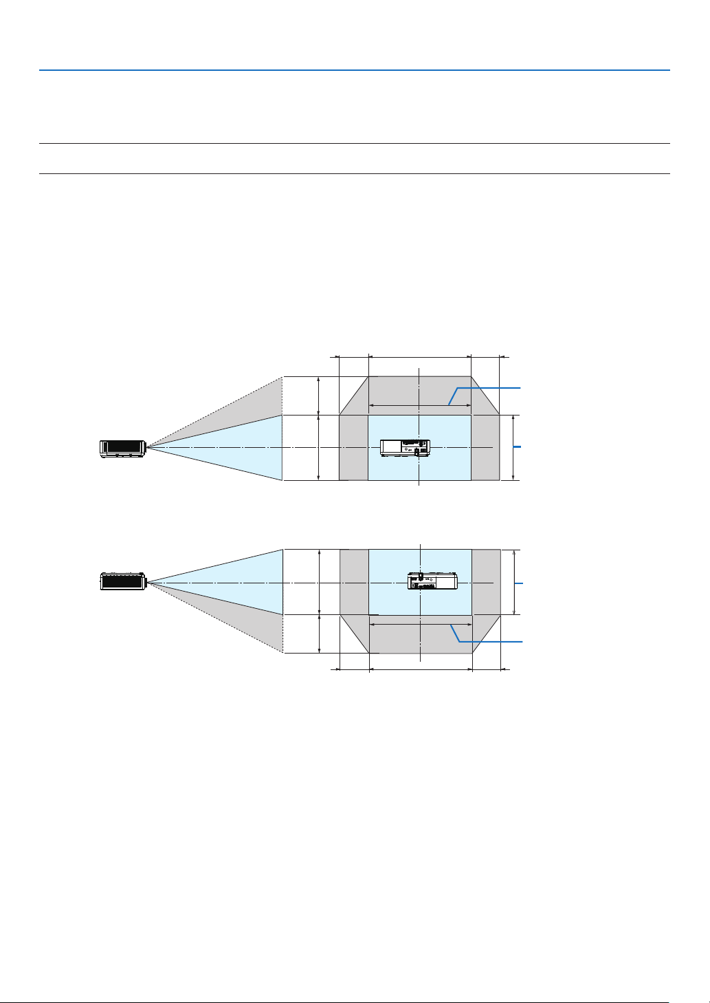
7. Installation and Connections
Lens shift range
This projector is equipped with a lens shift function (→ page 19) for adjusting the image position using dials. Lens
shifting is possible within the range shown below.
NOTE:
• In case lens shifted volume exceeds the below illustrated range, blur and shade may appear around ends of projected image.
Legend: V “Vertical” refers to the screen height and H “Horizontal” refers to the screen width. The lens shift range
is expressed as a ratio of height and width, respectively.
[PE506UL]
Lens shifting range:
Vertical direction: +60%, −0%
Horizontal direction: ±29%
DESKTOP FRONT, DESKTOP REAR
29% H29% H 100% H
60% V
100% V
Width of projected
image
Height of projected
image
CEILING FRONT, CEILING REAR
100% V
60% V
29% H29% H 100% H
Height of projected
image
Width of projected
image
(Example) When using to project on a 150" screen
According to the “Table of screen sizes and dimensions” (→ page 69) , H = 127.2"/323.1 cm, V = 79.5"/201.9 cm.
Adjustment range in the vertical direction: the projected image can be moved upwards 0.60 × 79.5"/201.9 cm ≈
47.7"/121 cm (when the lens is at the center position).
Adjustment range in the horizontal direction: the projected image can be moved to the left 0.29 × 127.2"/323.1 cm
≈ 36.9"/94 cm, to the right approximately 36.9"/94 cm.
* Figures differ by several % because the calculation is approximate.
73
Page 92
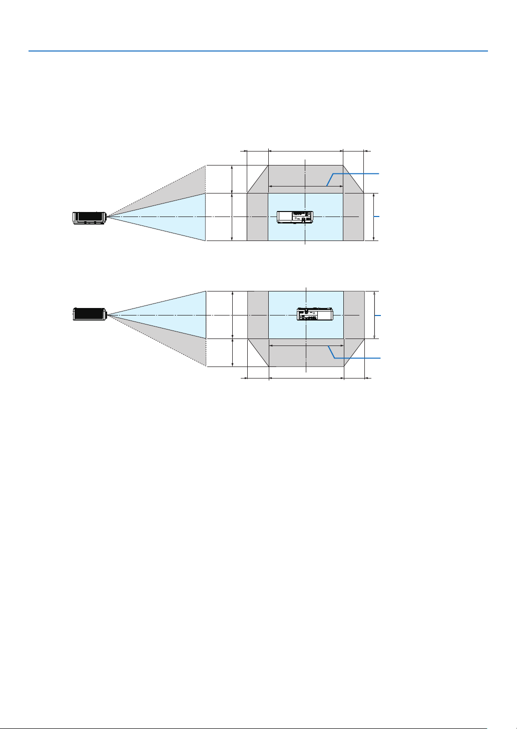
[PE506WL]
Lens shifting range:
Vertical direction: +55%, −0%
Horizontal direction: ±26%
DESKTOP FRONT, DESKTOP REAR
7. Installation and Connections
26% H26% H 100% H
55% V
100% V
Width of projected
image
Height of projected
image
CEILING FRONT, CEILING REAR
100% V
55% V
26% H26% H 100% H
Height of projected
image
Width of projected
image
(Example) When using to project on a 150" screen
According to the “Table of screen sizes and dimensions” (→ page 69), H = 127.2''/323.1 cm, V = 79.5''/201.9 cm.
Adjustment range in the vertical direction: the projected image can be moved upwards 0.55 × 79.5''/ 201.9 cm ≈
43.7''/111cm (when the lens is at the center position).
Adjustment range in the horizontal direction: the projected image can be moved to the left 0.26 × 127.2''/ 323.1cm
≈ 33.1''/84 cm, to the right approximately 33.1''/84 cm.
* Figures differ by several % because the calculation is approximate.
74
Page 93
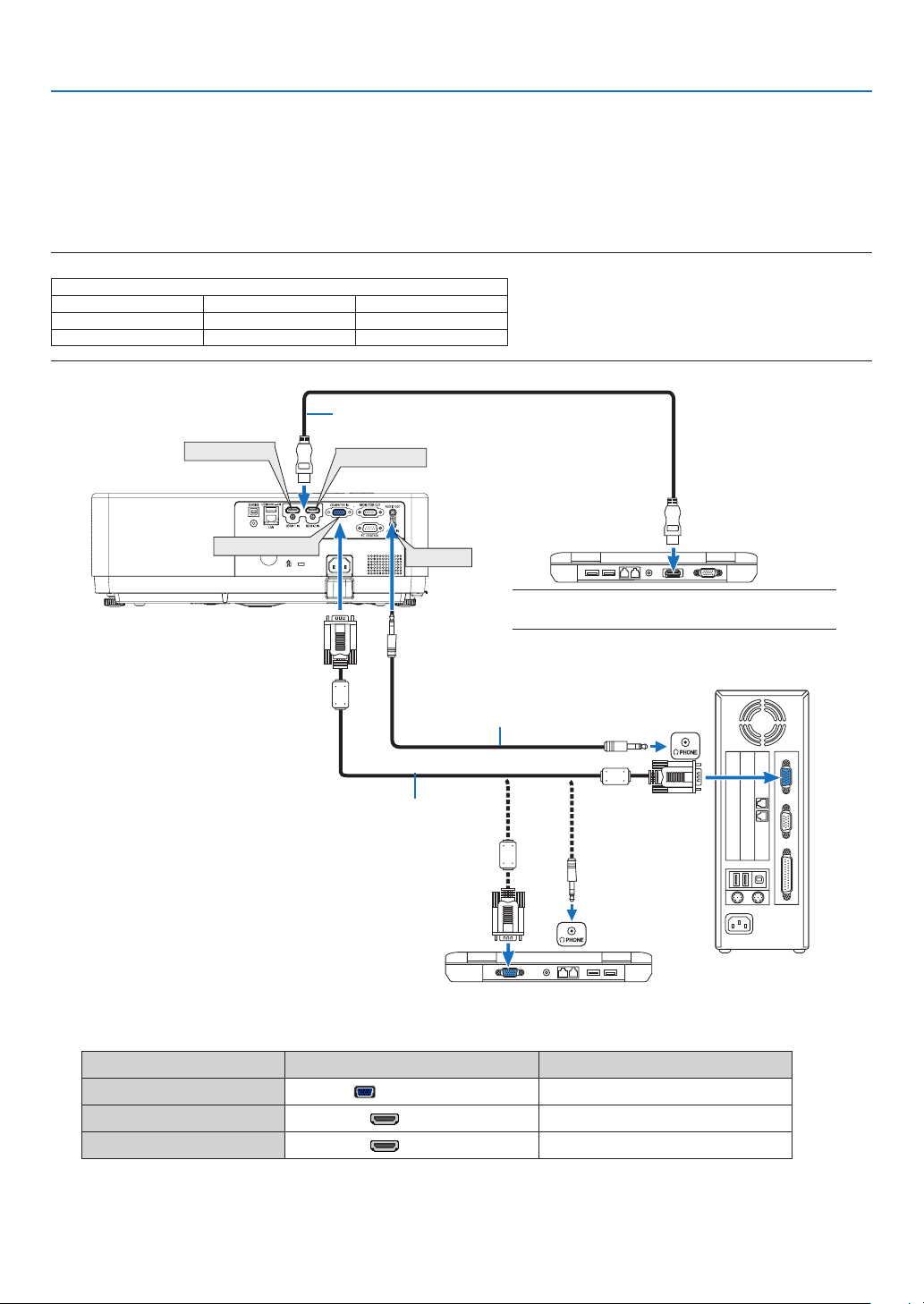
7. Installation and Connections
❷ Making Connections
Connecting Your Computer
Computer cable or HDMI can be used to connect to a computer. A computer cable (VGA) is supplied with the projector. Please get ready a suitable cable for the connection.
NOTE: Signals supported by Plug & Play (DDC2)
COMPUTER IN HDMI 1 IN HDMI 2 IN
analog digital digital
Yes Yes Yes
HDMI 1 IN
INPUT
HDMI cable (not supplied)
Use High Speed HDMI® Cable.
HDMI 2 IN
COMPUTER IN
AUDIO IN
NOTE: For Mac, use a commercially available pin adapter
(not supplied) to connect to your Mac’s video port.
Stereo mini-plug audio cable (not supplied)
Computer cable (VGA) (supplied)
To mini D-Sub 15-pin terminal on the
projector. It is recommended that you
use a commercially available distribu-
tion amplifier if connecting a signal cable
longer than the cable supplied.
• Select the source name for its appropriate input terminal after turning on the projector.
Input terminal
COMPUTER IN
INPUT button on the projector cabinet
Button on the remote control
COMPUTER
(COMPUTER)
HDMI 1 IN HDMI1 (HDMI 1)
HDMI 2 IN HDMI2 (HDMI 2)
75
Page 94
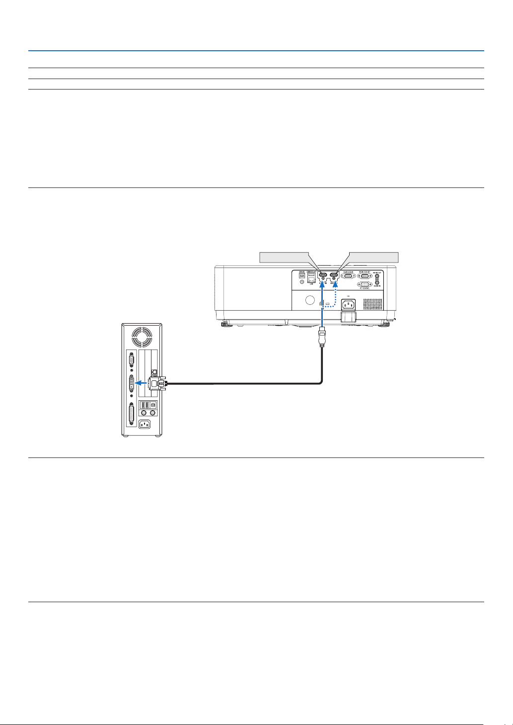
7. Installation and Connections
NOTE: The projector is not compatible with video decoded outputs of the NEC ISS-6020 switcher.
NOTE: An image may not be displayed correctly when a Video source is played back via a commercially available scan converter.
This is because the projector will process a video signal as a computer signal at the default setting. In that case, do the following.
* When an image is displayed with the lower and upper black portion of the screen or a dark image is not displayed correctly:
Project an image to fill the screen and then press the AUTO ADJ. button on the remote control or the projector cabinet.
Enabling the computer’s external display
Displaying an image on the notebook PC’s screen does not necessarily mean it outputs a signal to the projector.
When using a PC compatible laptop, a combination of function keys will enable/disable the external display.
Usually, the combination of the “Fn” key along with one of the 12 function keys gets the external display to come on or off. For example, NEC
laptops use Fn + F3, while Dell laptops use Fn + F8 key combinations to toggle through external display selections.
Cautions when using a DVI signal
• When the computer has a DVI output terminal, use a commercially available converter cable to connect the computer to the projector’s HDMI 1 or HDMI 2 input terminal (only digital video signals can be input).
HDMI 1 IN HDMI 2 IN
NOTE: When Viewing a DVI Digital Signal
• Turn off the power of the computer and projector before connecting.
• When a video deck is connected via a scan converter, etc., the display may not be correct during fast-forwarding and rewinding.
• Use a DVI-to-HDMI cable compliant with DDWG (Digital Display Working Group) DVI (Digital Visual Interface) revision 1.0 standard.
The cable should be within 197"/5 m long.
• Turn off the projector and the PC before connecting the DVI-to-HDMI cable.
• To project a DVI digital signal: Connect the cables, turn the projector on, then select the HDMI input. Finally, turn on your PC.
Failure to do so may not activate the digital output of the graphics card resulting in no picture being displayed. Should this happen, restart
your PC.
• Do not disconnect the DVI-to-HDMI cable while the projector is running. If the signal cable has been disconnected and then reconnected,
an image may not be correctly displayed. Should this happen, restart your PC.
• The COMPUTER video input terminals support Windows Plug and Play.
• A Mac signal adapter (commercially available) may be required to connect a Mac computer.
76
Page 95
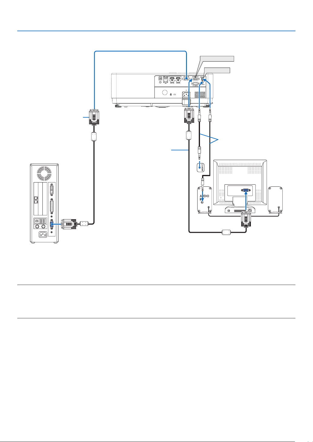
Connecting an External Monitor
Computer cable
(VGA) (supplied)
Computer cable
(VGA) (not supplied)
7. Installation and Connections
MONITOR OUT
AUDIO OUT
Stereo mini-plug audio
cable (not supplied)
You can connect a separate, external monitor to your projector to simultaneously view on a monitor the computer
analog image you’re projecting.
NOTE:
• The AUDIO OUT mini jack does not support earphone/headphone terminal.
• When audio equipment is connected, the projector speaker is disabled.
• The signal output from the MONITOR OUT of this projector is for projecting image on exclusive one display.
• MONITOR OUT function is not available in Standby mode: Normal and Standby mode: Network standby.
77
Page 96
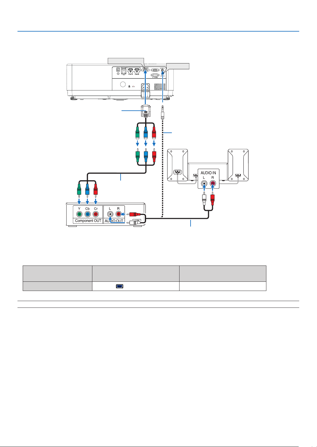
Connecting Component Input
COMPUTER IN
7. Installation and Connections
AUDIO IN
15-pin - to - RCA (female) × 3 cable adapter
DVD player
(ADP-CV1E)
Stereo mini plug - to - RCA audio cable (not supplied)
Audio Equipment
Component video RCA ×
3 cable (not supplied)
Audio cable (not supplied)
• Select the source name for its appropriate input terminal after turning on the projector.
Input terminal
COMPUTER IN
INPUT button on the projector
cabinet
COMPUTER
Button on the remote control
(COMPUTER)
NOTE: Refer to your DVD player’s owner’s manual for more information about your DVD player’s video output requirements.
78
Page 97
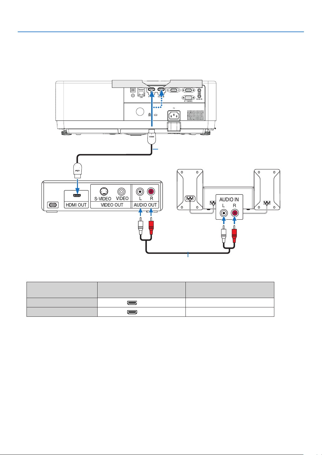
7. Installation and Connections
Connecting HDMI Input
You can connect the HDMI output of your DVD player, hard disk player, Blu-ray player, or notebook type PC to the
HDMI IN terminal of your projector.
HDMI 1 IN
HDMI 2 IN
HDMI cable (not supplied)
Use High Speed HDMI® Cable.
Audio cable (not supplied)
• Select the source name for its appropriate input terminal after turning on the projector.
Input terminal
HDMI 1 IN HDMI1 (HDMI1)
HDMI 2 IN HDMI2 (HDMI2)
INPUT button on the projector
cabinet
Button on the remote control
79
Page 98
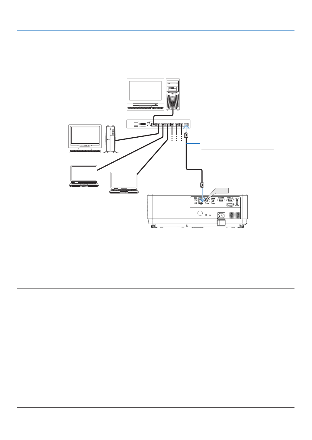
7. Installation and Connections
Connecting to a Wired LAN
The projector comes standard with a LAN port (RJ-45) which provides a LAN connection using a LAN cable.
To use a LAN connection, you are required to set the LAN on the projector menu. (→ page 55)
Example of LAN connection
Server
Hub
LAN cable (not supplied)
NOTE: Use a Category 5 or higher
LAN cable.
LAN
Connecting to a Wireless LAN
The USB Wireless LAN Unit also provides a wireless LAN connection.
Important:
• If you use the projector with the USB Wireless LAN Unit in the area where the use of wireless LAN equipment is
prohibited, remove the USB Wireless LAN Unit from the projector.
• Buy the appropriate USB Wireless LAN Unit for your country or area.
NOTE:
• The green LED on the USB Wireless LAN Unit flashes to show that the USB Wireless LAN Unit is working.
• Your computer’s wireless LAN adapter (or unit) must be complied with IEEE802.11b/g/n standard.
• When connecting a USB device and a network cable at the same time, there is highly possibility of interference when using a USB device
that is too large..It is recommended that users use smaller USB devices.
Attaching the USB Wireless LAN Unit
NOTE:
• The USB Wireless LAN Unit must be inserted into the USB Wireless LAN Unit port in the correct direction. It cannot be inserted in the
reverse direction. If the USB Wireless LAN Unit is inserted in the reverse direction with excessive force applied, the USB port may break.
• Before touching the USB Wireless LAN Unit, touch a metallic object (such as a door knob or aluminum window frame) to discharge the
static electricity from your body.
• Always insert or remove the USB Wireless LAN unit when the main power is turned off. Failure to do so may cause projector malfunction
or damage to the USB wireless LAN unit. If the projector will not work correctly, turn off the projector, disconnect the power cord, and
then connect it again.
• The USB port of the projector is common use for the VIEWER. When the USB memory is installed and activate the VIEWER, you can not
utilize wireless LAN.
80
Page 99
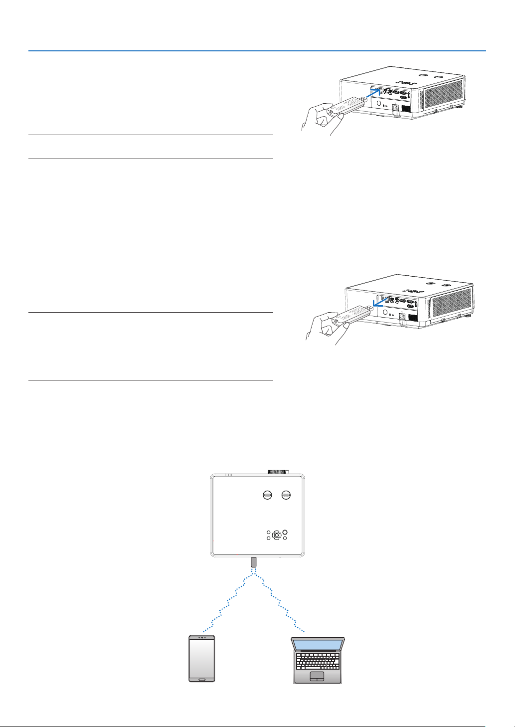
1. Press the POWER button to turn off the projector and set
it into standby condition, and disconnect the power cord.
2. Slowly insert the USB Wireless LAN Unit into the USB port.
Remove the cap from the USB Wireless LAN Unit, and then
insert it with the surface (side of indicator) facing down. Keep
the cap for later use.
NOTE:
• Do not force to insert the USB Wireless LAN Unit.
To remove the USB Wireless LAN Unit, disconnect the power cord
and use the above procedure.
NOTE:
• The green LED on the USB Wireless LAN Unit flashes to show that Wireless
LAN Unit is working. If the USB Wireless LAN Unit is incorrectly
attached, the blue LED will not flash.
• Do not press the button on the USB Wireless LAN Unit. The button will
not work with this model.
7. Installation and Connections
Connection Example [SIMPLE ACCESS POINT]
Set the projector as SIMPLE ACCESS POINT for connecting to terminals as computers and smart phones.
81
Page 100

7. Installation and Connections
(1) Press the MENU button on remote control or the top control panel, press button select [Expand] icon.
Press the ENTER or button.
(2) Press button select [Network setup] and press the ENTER or button.
(3) Press button select [Network setting] and press the ENTER button to enter.
(4) Press button to set Wireless LAN Setting "On" and press the ENTER button to confirm.
(5) Press button to select [Set], press the ENTER button to wait until the “Please wait..” message disappears.
NOTE:
• Data transmission between wireless LAN and wired LAN is not possible.
up to 20 units can be connected simultaneously. Recommend to connect approx. 10 units for normal operation.
82
 Loading...