

Page 1

ND-70895 (E)
ISSUE 1
STOCK # 200876
®
OAI System Manual
SEPTEMBER, 2000
NEC America, Inc.
Page 2

LIABILITY DISCLAIMER
NEC America, Inc. reserves t he right to change th e specifications, functions, or
features, at any time, without notice.
NEC America, Inc. has prepared this document for use by its employees and
customers. The information contained herein is the property of NEC America,
Inc. and shall not be reproduced without prior written approval from NEC
America, Inc.
NEAX and D
term
are registered trademarks of NEC Corporation.
All other brand or product names are or may be trademarks or registered
trademarks of, and are used to i dentify pr oducts or ser vices of, t heir respec tive
owners.
MS-DOS and Microsoft are registered trademarks of Microsoft Corporation.
Microsoft Windows 95 and Windows NT are trademarks of Microsoft
Corporation.
Copyright 2000
NEC America, Inc.
Printed in the U.S.A
Page 3

PAGE No.
i 1
ii 1
iii 1
iv
v 1
vi 1
1 1
2
3 1
4 1
5 1
6
7 1
8 1
9 1
10
11 1
12 1
13 1
14
15 1
16 1
17 1
18
19 1
20 1
21 1
22
23 1
24 1
25 1
26
27 1
28 1
29 1
30
31 1
32 1
Issue No.
12345678
1
1
1
1
1
1
1
1
1
PAGE N o.
33 1
34
35 1
36 1
37 1
38
39 1
40 1
41 1
42
43 1
44 1
45 1
46
47 1
48 1
49 1
50
51 1
52 1
53 1
54
55 1
56 1
57 1
58
59 1
60 1
61 1
62
63 1
64 1
65 1
66
67 1
68 1
69 1
70
Issue No.
12345678
1
1
1
1
1
1
1
1
1
1
ISSUE 1 ISSUE 2 ISSUE 3 ISSUE 4
DATE SEPTEMBER, 2000 DATE DATE DATE
ISSUE 5 ISSUE 6 ISSUE 7 ISSUE 8
DA TE DATE DATE DATE
NEAX2400 IMX
OAI System Manual
Issue Revision Sheet 1/2
ND-70895 (E) ISSUE 1
Page 4

PAGE No.
71 1
72 1
73 1
74
75 1
76 1
77 1
78
79 1
80 1
81 1
82
83 1
84 1
85 1
86
87 1
88 1
89 1
90
91 1
92 1
93 1
94
95 1
96 1
Issue No.
12345678
1
1
1
1
1
1
PAGE No.
Issue No.
12345678
ISSUE 1 ISSUE 2 ISSUE 3 ISSUE 4
DATE SEPTEMBER, 2000 DATE DATE DATE
ISSUE 5 ISSUE 6 ISSUE 7 ISSUE 8
DA TE DATE DATE DATE
NEAX2400 IMX
OAI System Manual
Issue Revision Sheet 2/2
ND-70895 (E) ISSUE 1
Page 5

ND-70895 (E)
ISSUE 1
SEPTEMBER, 2000
NEAX2400 IMX
OAI System Manual
TABLE OF CONTENTS
Page
CHAPTER 1 INTRODUCTION . . . . . . . . . . . . . . . . . . . . . . . . . . . . . . . . . . . . . . . . . . . . . . . . . . . . . . . . . . . 1
1. General. . . . . . . . . . . . . . . . . . . . . . . . . . . . . . . . . . . . . . . . . . . . . . . . . . . . . . . . . . . . . . . . . . . . . . . . . 1
2. How to Follow the Manual. . . . . . . . . . . . . . . . . . . . . . . . . . . . . . . . . . . . . . . . . . . . . . . . . . . . . . . . . . . 1
2.1 Configuration of This Manual . . . . . . . . . . . . . . . . . . . . . . . . . . . . . . . . . . . . . . . . . . . . . . . . . . 1
2.2 Related Reference Manual . . . . . . . . . . . . . . . . . . . . . . . . . . . . . . . . . . . . . . . . . . . . . . . . . . . 2
CHAPTER 2 SYSTEM OUTLINE . . . . . . . . . . . . . . . . . . . . . . . . . . . . . . . . . . . . . . . . . . . . . . . . . . . . . . . . . 3
1. General. . . . . . . . . . . . . . . . . . . . . . . . . . . . . . . . . . . . . . . . . . . . . . . . . . . . . . . . . . . . . . . . . . . . . . . . . 3
2. System Outline . . . . . . . . . . . . . . . . . . . . . . . . . . . . . . . . . . . . . . . . . . . . . . . . . . . . . . . . . . . . . . . . . . . 4
2.1 OAI (Open Application Interface) System . . . . . . . . . . . . . . . . . . . . . . . . . . . . . . . . . . . . . . . . 4
2.2 Software Structure in the OAI System . . . . . . . . . . . . . . . . . . . . . . . . . . . . . . . . . . . . . . . . . . . 4
2.2.1 Facilities . . . . . . . . . . . . . . . . . . . . . . . . . . . . . . . . . . . . . . . . . . . . . . . . . . . . . . . . . . . 6
2.2.2 Join of Facilities and Application. . . . . . . . . . . . . . . . . . . . . . . . . . . . . . . . . . . . . . . . . 13
2.2.3 Cope of Application in changeover of CPU System . . . . . . . . . . . . . . . . . . . . . . . . . . 13
3. System Configuration . . . . . . . . . . . . . . . . . . . . . . . . . . . . . . . . . . . . . . . . . . . . . . . . . . . . . . . . . . . . . . 14
4. Interface with External Computer . . . . . . . . . . . . . . . . . . . . . . . . . . . . . . . . . . . . . . . . . . . . . . . . . . . . . 17
4.1 Conditions for Interface with External Computer . . . . . . . . . . . . . . . . . . . . . . . . . . . . . . . . . . . 17
CHAPTER 3 INSTALLATION PROCEDURE . . . . . . . . . . . . . . . . . . . . . . . . . . . . . . . . . . . . . . . . . . . . . . . .19
1. General. . . . . . . . . . . . . . . . . . . . . . . . . . . . . . . . . . . . . . . . . . . . . . . . . . . . . . . . . . . . . . . . . . . . . . . . . 19
2. Cable Connections with External Computer . . . . . . . . . . . . . . . . . . . . . . . . . . . . . . . . . . . . . . . . . . . . . 20
2.1 Cable Connections between OAI System and External Computer . . . . . . . . . . . . . . . . . . . . . 20
3. OAI Software Installation. . . . . . . . . . . . . . . . . . . . . . . . . . . . . . . . . . . . . . . . . . . . . . . . . . . . . . . . . . . . 21
4. Upgrading OAI System from NEAX2400 ICS to NEAX2400 IMX . . . . . . . . . . . . . . . . . . . . . . . . . . . . . 23
4.1 Up Grading Procedure. . . . . . . . . . . . . . . . . . . . . . . . . . . . . . . . . . . . . . . . . . . . . . . . . . . . . . . 23
CHAPTER 4 COMMANDS . . . . . . . . . . . . . . . . . . . . . . . . . . . . . . . . . . . . . . . . . . . . . . . . . . . . . . . . . . . . . . 25
1. General. . . . . . . . . . . . . . . . . . . . . . . . . . . . . . . . . . . . . . . . . . . . . . . . . . . . . . . . . . . . . . . . . . . . . . . . . 25
2. Configuration of Commands for OAI System . . . . . . . . . . . . . . . . . . . . . . . . . . . . . . . . . . . . . . . . . . . . 26
2.1 Configuration of Commands . . . . . . . . . . . . . . . . . . . . . . . . . . . . . . . . . . . . . . . . . . . . . . . . . . 26
3. Commands . . . . . . . . . . . . . . . . . . . . . . . . . . . . . . . . . . . . . . . . . . . . . . . . . . . . . . . . . . . . . . . . . . . . . . 27
3.1 List of Commands . . . . . . . . . . . . . . . . . . . . . . . . . . . . . . . . . . . . . . . . . . . . . . . . . . . . . . . . . . 27
3.2 Outline of Commands for OAI System. . . . . . . . . . . . . . . . . . . . . . . . . . . . . . . . . . . . . . . . . . . 28
3.3 Items to Be Explained by Each Command . . . . . . . . . . . . . . . . . . . . . . . . . . . . . . . . . . . . . . . 28
ND-70895 (E) TABLE OF CONTENTS
Page i
Revision 1.0
Page 6

TABLE OF CONTENTS (CONTINUED)
Page
AADT . . . . . . . . . . . . . . . . . . . . . . . . . . . . . . . . . . . . . . . . . . . . . . . . . . . . . . . . . . . . . . . . . . . . . . . . . . . . . 29
ACNO . . . . . . . . . . . . . . . . . . . . . . . . . . . . . . . . . . . . . . . . . . . . . . . . . . . . . . . . . . . . . . . . . . . . . . . . . . . . . 31
AKYD . . . . . . . . . . . . . . . . . . . . . . . . . . . . . . . . . . . . . . . . . . . . . . . . . . . . . . . . . . . . . . . . . . . . . . . . . . . . . 33
AMNO. . . . . . . . . . . . . . . . . . . . . . . . . . . . . . . . . . . . . . . . . . . . . . . . . . . . . . . . . . . . . . . . . . . . . . . . . . . . . 34
AOAC . . . . . . . . . . . . . . . . . . . . . . . . . . . . . . . . . . . . . . . . . . . . . . . . . . . . . . . . . . . . . . . . . . . . . . . . . . . . . 36
AOKC . . . . . . . . . . . . . . . . . . . . . . . . . . . . . . . . . . . . . . . . . . . . . . . . . . . . . . . . . . . . . . . . . . . . . . . . . . . . . 38
ASPA . . . . . . . . . . . . . . . . . . . . . . . . . . . . . . . . . . . . . . . . . . . . . . . . . . . . . . . . . . . . . . . . . . . . . . . . . . . . . 42
ASYD . . . . . . . . . . . . . . . . . . . . . . . . . . . . . . . . . . . . . . . . . . . . . . . . . . . . . . . . . . . . . . . . . . . . . . . . . . . . . 43
DFLN . . . . . . . . . . . . . . . . . . . . . . . . . . . . . . . . . . . . . . . . . . . . . . . . . . . . . . . . . . . . . . . . . . . . . . . . . . . . . 53
ASYDN . . . . . . . . . . . . . . . . . . . . . . . . . . . . . . . . . . . . . . . . . . . . . . . . . . . . . . . . . . . . . . . . . . . . . . . . . . . . 54
ASYDL . . . . . . . . . . . . . . . . . . . . . . . . . . . . . . . . . . . . . . . . . . . . . . . . . . . . . . . . . . . . . . . . . . . . . . . . . . . . 56
CHAPTER 5 OFFICE DATA DESIGN . . . . . . . . . . . . . . . . . . . . . . . . . . . . . . . . . . . . . . . . . . . . . . . . . . . . . . 59
1. General . . . . . . . . . . . . . . . . . . . . . . . . . . . . . . . . . . . . . . . . . . . . . . . . . . . . . . . . . . . . . . . . . . . . . . . . 59
2. Procedure for Setting Basic Office Data for OAI System. . . . . . . . . . . . . . . . . . . . . . . . . . . . . . . . . . . 60
2.1 Data for OAI System . . . . . . . . . . . . . . . . . . . . . . . . . . . . . . . . . . . . . . . . . . . . . . . . . . . . . . . . 60
2.2 Data for OAI Terminal . . . . . . . . . . . . . . . . . . . . . . . . . . . . . . . . . . . . . . . . . . . . . . . . . . . . . . . 61
3. Procedure for Setting Office Data for OAI Services. . . . . . . . . . . . . . . . . . . . . . . . . . . . . . . . . . . . . . . 62
3.1 Switch Control Facility (SCF) . . . . . . . . . . . . . . . . . . . . . . . . . . . . . . . . . . . . . . . . . . . . . . . . . 62
3.1.1 Functional Outline . . . . . . . . . . . . . . . . . . . . . . . . . . . . . . . . . . . . . . . . . . . . . . . . . . . 62
3.1.2 Using Conditions . . . . . . . . . . . . . . . . . . . . . . . . . . . . . . . . . . . . . . . . . . . . . . . . . . . . 63
3.1.3 Data Programming . . . . . . . . . . . . . . . . . . . . . . . . . . . . . . . . . . . . . . . . . . . . . . . . . . . 65
3.2 Call ID Notification (SMFN for ISDN) . . . . . . . . . . . . . . . . . . . . . . . . . . . . . . . . . . . . . . . . . . . 66
3.2.1 Functional Outline . . . . . . . . . . . . . . . . . . . . . . . . . . . . . . . . . . . . . . . . . . . . . . . . . . . 66
3.2.2 Using Conditions . . . . . . . . . . . . . . . . . . . . . . . . . . . . . . . . . . . . . . . . . . . . . . . . . . . . 66
3.2.3 Data Programming . . . . . . . . . . . . . . . . . . . . . . . . . . . . . . . . . . . . . . . . . . . . . . . . . . . 67
3.3 MWL Control (SSF) STEP-1. . . . . . . . . . . . . . . . . . . . . . . . . . . . . . . . . . . . . . . . . . . . . . . . . . 68
3.3.1 Functional Outline . . . . . . . . . . . . . . . . . . . . . . . . . . . . . . . . . . . . . . . . . . . . . . . . . . . 68
3.3.2 Using Conditions . . . . . . . . . . . . . . . . . . . . . . . . . . . . . . . . . . . . . . . . . . . . . . . . . . . . 69
3.3.3 Data Programming . . . . . . . . . . . . . . . . . . . . . . . . . . . . . . . . . . . . . . . . . . . . . . . . . . . 71
3.4 TCP/IP Address (Assignment from MAT) . . . . . . . . . . . . . . . . . . . . . . . . . . . . . . . . . . . . . . . . 72
3.4.1 Functional Outline . . . . . . . . . . . . . . . . . . . . . . . . . . . . . . . . . . . . . . . . . . . . . . . . . . . 72
3.4.2 Using Conditions . . . . . . . . . . . . . . . . . . . . . . . . . . . . . . . . . . . . . . . . . . . . . . . . . . . . 72
3.4.3 Data Programming . . . . . . . . . . . . . . . . . . . . . . . . . . . . . . . . . . . . . . . . . . . . . . . . . . . 73
3.5 Name Display . . . . . . . . . . . . . . . . . . . . . . . . . . . . . . . . . . . . . . . . . . . . . . . . . . . . . . . . . . . . . 74
3.5.1 Functional Outline . . . . . . . . . . . . . . . . . . . . . . . . . . . . . . . . . . . . . . . . . . . . . . . . . . . 74
3.5.2 Using Conditions . . . . . . . . . . . . . . . . . . . . . . . . . . . . . . . . . . . . . . . . . . . . . . . . . . . . 74
3.5.3 Data Programming (Set up from User’s Application) . . . . . . . . . . . . . . . . . . . . . . . . . 75
3.6 Inter Node Name Display . . . . . . . . . . . . . . . . . . . . . . . . . . . . . . . . . . . . . . . . . . . . . . . . . . . . 76
3.6.1 Functional Outline . . . . . . . . . . . . . . . . . . . . . . . . . . . . . . . . . . . . . . . . . . . . . . . . . . . 76
3.6.2 Using Conditions . . . . . . . . . . . . . . . . . . . . . . . . . . . . . . . . . . . . . . . . . . . . . . . . . . . . 76
3.6.3 Data Programming (Set up from User’s Application) . . . . . . . . . . . . . . . . . . . . . . . . . 78
3.7 OAI Fusion . . . . . . . . . . . . . . . . . . . . . . . . . . . . . . . . . . . . . . . . . . . . . . . . . . . . . . . . . . . . . . . 79
3.7.1 OAI Terminal Anywhere. . . . . . . . . . . . . . . . . . . . . . . . . . . . . . . . . . . . . . . . . . . . . . . 79
3.7.2 Multiple IPs. . . . . . . . . . . . . . . . . . . . . . . . . . . . . . . . . . . . . . . . . . . . . . . . . . . . . . . . . 81
3.7.3 Example of Use of Facility on Fusion Network. . . . . . . . . . . . . . . . . . . . . . . . . . . . . . 85
TABLE OF CONTENTS ND-70895 (E)
Page ii
Revision 1.0
Page 7

TABLE OF CONTENTS (CONTINUED)
Page
CHAPTER 6 MAINTENANCE . . . . . . . . . . . . . . . . . . . . . . . . . . . . . . . . . . . . . . . . . . . . . . . . . . . . . . . . . . . 87
1. General . . . . . . . . . . . . . . . . . . . . . . . . . . . . . . . . . . . . . . . . . . . . . . . . . . . . . . . . . . . . . . . . . . . . . . . . 87
2. Maintenance. . . . . . . . . . . . . . . . . . . . . . . . . . . . . . . . . . . . . . . . . . . . . . . . . . . . . . . . . . . . . . . . . . . . . 88
2.1 Routine Maintenance . . . . . . . . . . . . . . . . . . . . . . . . . . . . . . . . . . . . . . . . . . . . . . . . . . . . . . . 88
2.1.1 System Messages and Lamp Indications on TOPU. . . . . . . . . . . . . . . . . . . . . . . . . . 88
3. System Messages . . . . . . . . . . . . . . . . . . . . . . . . . . . . . . . . . . . . . . . . . . . . . . . . . . . . . . . . . . . . . . . . 89
3.1 Outline. . . . . . . . . . . . . . . . . . . . . . . . . . . . . . . . . . . . . . . . . . . . . . . . . . . . . . . . . . . . . . . . . . . 89
3.2 Message Detail Data. . . . . . . . . . . . . . . . . . . . . . . . . . . . . . . . . . . . . . . . . . . . . . . . . . . . . . . . 90
3.2.1 Message Detail Data of System Message “4-R” . . . . . . . . . . . . . . . . . . . . . . . . . . . . 90
3.2.2 Message Detail Data of System Message “26-V” . . . . . . . . . . . . . . . . . . . . . . . . . . . 91
4. Fault Diagnosis. . . . . . . . . . . . . . . . . . . . . . . . . . . . . . . . . . . . . . . . . . . . . . . . . . . . . . . . . . . . . . . . . . . 92
4.1 General . . . . . . . . . . . . . . . . . . . . . . . . . . . . . . . . . . . . . . . . . . . . . . . . . . . . . . . . . . . . . . . . . . 92
4.2 Diagnosis from System Messages . . . . . . . . . . . . . . . . . . . . . . . . . . . . . . . . . . . . . . . . . . . . . 93
4.2.1 TCP/IP Link Failure . . . . . . . . . . . . . . . . . . . . . . . . . . . . . . . . . . . . . . . . . . . . . . . . . . 94
ND-70895 (E) TABLE OF CONTENTS
Page iii
Revision 1.0
Page 8

LIST OF FIGURES
Figure Title Page
Figure 2-1 Software Structure in the OAI System . . . . . . . . . . . . . . . . . . . . . . . . . . . . . . . . . . . . . . . . . . . 5
Figure 2-2 Concept of MSF . . . . . . . . . . . . . . . . . . . . . . . . . . . . . . . . . . . . . . . . . . . . . . . . . . . . . . . . . . . . 6
Figure 2-3 Concept of TMF . . . . . . . . . . . . . . . . . . . . . . . . . . . . . . . . . . . . . . . . . . . . . . . . . . . . . . . . . . . . 7
Figure 2-4 Concept of ETF . . . . . . . . . . . . . . . . . . . . . . . . . . . . . . . . . . . . . . . . . . . . . . . . . . . . . . . . . . . . 7
Figure 2-5 Concept of ACF . . . . . . . . . . . . . . . . . . . . . . . . . . . . . . . . . . . . . . . . . . . . . . . . . . . . . . . . . . . . 8
Figure 2-6 Concept of FLF . . . . . . . . . . . . . . . . . . . . . . . . . . . . . . . . . . . . . . . . . . . . . . . . . . . . . . . . . . . . 8
Figure 2-7 Concept of TCF . . . . . . . . . . . . . . . . . . . . . . . . . . . . . . . . . . . . . . . . . . . . . . . . . . . . . . . . . . . . 9
Figure 2-8 Concept of KTF . . . . . . . . . . . . . . . . . . . . . . . . . . . . . . . . . . . . . . . . . . . . . . . . . . . . . . . . . . . . 9
Figure 2-9 Concept of NTF . . . . . . . . . . . . . . . . . . . . . . . . . . . . . . . . . . . . . . . . . . . . . . . . . . . . . . . . . . . . 10
Figure 2-10 Concept of SCF . . . . . . . . . . . . . . . . . . . . . . . . . . . . . . . . . . . . . . . . . . . . . . . . . . . . . . . . . . . . 10
Figure 2-11 Concept of RCF . . . . . . . . . . . . . . . . . . . . . . . . . . . . . . . . . . . . . . . . . . . . . . . . . . . . . . . . . . . . 11
Figure 2-12 Concept of MRF. . . . . . . . . . . . . . . . . . . . . . . . . . . . . . . . . . . . . . . . . . . . . . . . . . . . . . . . . . . . 11
Figure 2-13 Concept of ATF . . . . . . . . . . . . . . . . . . . . . . . . . . . . . . . . . . . . . . . . . . . . . . . . . . . . . . . . . . . . 12
Figure 2-14 IP Single System Configuration . . . . . . . . . . . . . . . . . . . . . . . . . . . . . . . . . . . . . . . . . . . . . . . . 15
Figure 2-15 IP Dual System Configuration . . . . . . . . . . . . . . . . . . . . . . . . . . . . . . . . . . . . . . . . . . . . . . . . . 16
Figure 3-1 Cable Connections Between OAI System and External Computer . . . . . . . . . . . . . . . . . . . . . 20
Figure 4-1 Configuration of Commands of the NEAX2400 IMX OAI System . . . . . . . . . . . . . . . . . . . . . . 26
Figure 4-2 Interrelation among OAI System Commands. . . . . . . . . . . . . . . . . . . . . . . . . . . . . . . . . . . . . . 28
Figure 5-1 Network Configuration of OAI systems . . . . . . . . . . . . . . . . . . . . . . . . . . . . . . . . . . . . . . . . . . 82
Figure 6-1 Flow of Maintenance Works. . . . . . . . . . . . . . . . . . . . . . . . . . . . . . . . . . . . . . . . . . . . . . . . . . . 87
Figure 6-2 Flow of Fault Repair. . . . . . . . . . . . . . . . . . . . . . . . . . . . . . . . . . . . . . . . . . . . . . . . . . . . . . . . . 92
Figure 6-3 Flow of Diagnosis out of System Messages . . . . . . . . . . . . . . . . . . . . . . . . . . . . . . . . . . . . . . 93
ND-70895 (E) LIST OF FIGURES
Page iv
Revision 1.0
Page 9

LIST OF TABLES
Table Title Page
Table 1-1 Configuration of This Manual. . . . . . . . . . . . . . . . . . . . . . . . . . . . . . . . . . . . . . . . . . . . . . . . . . 1
Table 1-2 Related Reference Manual . . . . . . . . . . . . . . . . . . . . . . . . . . . . . . . . . . . . . . . . . . . . . . . . . . . 2
Table 2-1 Interface Conditions of the Circuit Card . . . . . . . . . . . . . . . . . . . . . . . . . . . . . . . . . . . . . . . . . . 17
Table 4-1 OAI System Command Table List . . . . . . . . . . . . . . . . . . . . . . . . . . . . . . . . . . . . . . . . . . . . . . 27
Table 4-2 Supplementary Service Codes. . . . . . . . . . . . . . . . . . . . . . . . . . . . . . . . . . . . . . . . . . . . . . . . . 42
Table 5-1 OAI Software and System Data. . . . . . . . . . . . . . . . . . . . . . . . . . . . . . . . . . . . . . . . . . . . . . . . 83
Table 6-1 Relationship between System Messages and Alarm Lamps on TOPU . . . . . . . . . . . . . . . . . . 88
Table 6-2 System Messages of OAI System . . . . . . . . . . . . . . . . . . . . . . . . . . . . . . . . . . . . . . . . . . . . . . 89
Table 6-3 Error Code . . . . . . . . . . . . . . . . . . . . . . . . . . . . . . . . . . . . . . . . . . . . . . . . . . . . . . . . . . . . . . . . 90
Table 6-4 Repairing Procedure for TCP/IP Link Failure (Message “4-R”) . . . . . . . . . . . . . . . . . . . . . . . . 94
Table 6-5 Repairing Procedure for TCP/IP Link Failure (Message “26-V”) . . . . . . . . . . . . . . . . . . . . . . . 94
ND-70895 (E) LIST OF TABLES
Page v
Revision 1.0
Page 10

This page is for your notes.
LIST OF TABLES ND-70895 (E)
Page vi
Revision 1.0
Page 11

CHAPTER 1 INTRODUCTION
1. General
This manual describes the outline, installation procedure/installation tests, and various phases of maintenance
work of an OAI (Open Application Interface) system which realizes the NEAX2400 IMX and a computer
system.
2. How to Follow the Manual
2.1 Configuration of This Manual
Configuration of this manual is shown in Table 1-1.
Table 1-1 Configuration of This Manual
CHAPTER TITLE CONTENTS
2 SYSTEM OUTLINE
3
4 COMMANDS
5 OFFICE DATA DESIGN
6 MAINTENANCE
INSTALLATION
PROCEDURE
This chapter describes the concept, function and configuration of the
NEAX2400 IMX OAI System
This chapter describes the installa t ion procedure for NEAX2400 IMX
OAI System
This chapter describes the commands that are used in NEAX2400 IMX
OAI System
This chapter describes the procedure for setting the of fice data req uired
in NEAX2400 IMX OAI System
This chapter describes the maintenance, fault diagnosis and fault repair
procedure of NEAX2400 IMX OAI System
ND-70895 (E) CHAPTER 1
Page 1
Revision 1.0
Page 12

INTRODUCTION
How to Follow the Manual
2.2 Related Reference Manual
The installation tasks for the NEAX2400 IMX OAI System consist of those related to the NEAX2400 IMX
system and those related to the OAI functions. Since this manual describes the tasks pertaining to the OAI
functions, it must be used together with the following manuals that describe tasks pertaining to t he NEAX2400
IMX itself when performing tasks pertaining to the NEAX2400 IMX OAI System.
Table 1-2 Related Reference Manual
MANUALS FOR NEAX2400 IMX RELATIONS HIP WITH THIS MANUAL
Installation Manual
Feature Programming Manual
System Operations and Maintenance
Manual
Office Data Specification
When performing installation and installation tests of the NEAX2400 IMX
OAI System, these manuals are to be used together with Chapter 3, "INSTAL-
LATION PROCEDURE" and also with “Circuit Card Manual”.
When performing maintenance jobs on the NEAX2400 IMX OAI System, this
manual is to be used together with Chapter 6, "MAINTENANCE" of this manual.
When performing installation tests and maintenance jobs on the NEAX2400
IMX OAI System, this manual is to be used together with Chapter 4, "COM-
MANDS" of this manual.
CHAPTER 1 ND-70895 (E)
Page 2
Revision 1.0
Page 13

CHAPTER 2 SYSTEM OUTLINE
1. General
This chapter describes the concept, functions, and conf iguration of the NEAX2400 IMX OAI System.
Before performing installation and/or maintenance of the NEAX2400 IMX OAI System, read this chapter
carefully.
The contents of Chapter 2 are outlined below.
• System Outline
Explains the outline of the OAI system
• System Configuration
Explains the configuration of the OAI system
• Interface with External Computer (General-Purpose Information Processing Equipment)
Explains the conditions for interface with external computer, and use of the related circuit cards
ND-70895 (E) CHAPTER 2
Page 3
Revision 1.0
Page 14

SYSTEM OUTLINE
System Outline
2. System Outline
2.1 OAI (Open Application Interface) System
1. The OAI system is the interface that joins a variety of facilities of the NEAX2400 IMX to th e app lica ti on
programs of the external computer (general-purpose information processing equipment) of the user.
2. The NEAX2400 IMX can be controlled by the external computer through the OAI system.
3. The OAI system diversifies the information processing functions of the NEAX2400 IMX, thus offering
users’ unique added values.
4. For implementing the OAI system, an Interface Processor (IP) is provided to the NEAX2400 IMX.
5. The IP controls the communication protocol between the NEAX2400 IMX and the UAP (User’s
Application Process or of the e xte rnal co mpute r) in accorda nce with the basic re fe rence model of th e Open
Systems Interconnecti on (OSI ) standar di zed by t he ISO (
Note
).
Note:
International Organization for Standar dization (ISO)
2.2 Software S tructure in the OAI System
The software structure in the OAI system is shown in Figure 2-1. So far, the software structure of the
NEAX2400 IMX is generally catego ri zed into three major blocks: Input Processing Block, Internal Processi ng
Block, and Output Processing Block. When the Input Processing Block detects a call, the Internal Processing
Block analyzes and identifies the call. In accordance with the result of this processing, the Output Processing
Block executes required switching operations, controlling of lamps/keys, etc. To meet these processing
requirements, a conventional arrangement is made every time a request for the application software arises. The
modules of the Input Pr ocessing Block and the Out put Processing Block ar e replaced with those corresponding
to such a reque st. However, in the case of the OAI syst em, each unit func tion to be made availa ble for the
computer in the Input Processi ng Block and the Output Proces sing Block is defined as a facility (each slant lined
portion in Figure 2-1) in advance, so that each of these facilities may be directly controlled by the external
computer through the OAI interface. For example, the key information input by processing of key receiving is
not processed withi n NEAX24 00 IM X, but is analyzed by the extern al computer. As a result of this processing
by the external computer, all the related messages are shown on a digital display and a lamp display at
corresponding termi nals. In other words, the OAI interface has relea sed the functio n of the conventional in ternal
processing to the external computers .
CHAPTER 2 ND-70895 (E)
Page 4
Revision 1.0
Page 15

SYSTEM OUTLINE
System Outline
Input Processing
Block
Digit Count
Key
Receiving
Off-Hook/
On-Hook
Monitor
Queue
Internal
Processing Block
Digit
Analysis
Key
Analysis
Trunk
Selection
Subscriber
Class
Identification
Switch
Selection
Queue
Output Processing
Block
Switch Control
Digit Display
Lamp Display
Other I
Other I
Note:
portion is
the unit function
(partial) to be
released by the OAI
system.
Other l
Other m Other n
OAI Interface
Processing by External Computer
Figure 2-1 Software Structure in the OAI System
Other l
Equivalent to the
internal processing
of the NEAX2400 IMX
ND-70895 (E) CHAPTER 2
Page 5
Revision 1.0
Page 16

SYSTEM OUTLINE
System Outline
2.2.1 Facilities
Each of the unit functions of the NEAX2400 IMX, such as switch control function, terminal control
function, etc., that can be controlled by the application of the computer is referred to as “facility”. The
facilities ca n be cat e goriz ed in tw o kinds as per the o per ating patte rn; on e is “Pr o vider Fa cili ty ” and th e
other is “Pe rf ormer Facility”.
• Provider Facility
A facility of this kind is capable of communicating with one Application Program (AP) on the
computer, and executes start-up, etc. of an AP on the computer.
• Perfo rmer Facility
A facility of this kind is capable of communicating with plural application programs (AP) on the
computer. It is activated from each AP as the common facility and executes required processing in
accordance with the control information given from the AP.
Each of the m ain facilities is o ut lined in the foll owing.
1. Provider Facilities
(a) Terminal Mode Set Facility (MSF)
With a specific key depressed on a ter m inal, this facility sets terminal mode. When terminal mode is
set by this facility, a communication path is set up between the terminal and the AP on the computer.
(Figure 2-2)
Note:
Key operation
Terminal (D
term
)
NEAX2400 IMX
MSF
(Setting of Communication Path)
Figure 2-2 Concept of MSF
The external computer is referred to as the computer.
The Computer
AP
CHAPTER 2 ND-70895 (E)
Page 6
Revision 1.0
Page 17

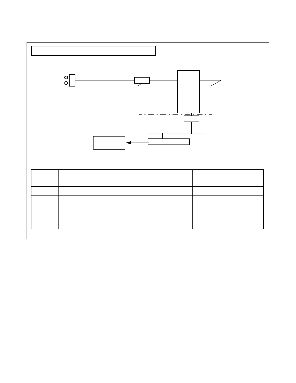
(b) Ter minal Multiple Info rmation Transf er Facility (TMF)
This facility executes batch transfer of dial number information entered from a terminal, card
information provided from the card reader, etc. to the AP. (Figure 2-3)
Dial, key, card input
SYSTEM OUTLINE
System Outline
Terminal (D
term
)
Card Reader
(c) Call Event Transfer Facility (ETF)
This facility edi ts the de tail ed data ( call du ratio n, et c.) pertai ning to calls at termin als acc ommodat ed
in the NEAX2400 IMX, and provides the edited information to the comput er. (Figure 2-4)
Terminal (D
term
)
NEAX2400 IMX
TMF
(Batch Transfer)
Figure 2-3 Concept of TMF
The Computer
AP
NEAX2400 IMX
ETF
(Transfer of Call Detailed Information)
Figure 2-4 Concept of ETF
ND-70895 (E) CHAPTER 2
The Computer
AP
(Starting)
Page 7
Revision 1.0
Page 18

SYSTEM OUTLINE
System Outline
(d) Authorization Code Facility (ACF)
Upon accepting a connection request and/or a service request from a terminal, this facility transfers
the ID code o f that specific terminal to the AP and also execu tes either connec tion processing or
connection restricti ng processing in accordance with the restriction class information returned fr om
the computer. (Figure 2-5)
(ID code input)
NEAX2400 IMX
Terminal
(D
term
)
ACF
Note: Connection Processing or Connection Restricting Processing
Figure 2-5 Concept of ACF
(e) Free Location Facility (FLF)
This facility establishes the co rrespondence between the extension number alloc ated to a terminal
and the user’s unique ID code in accordance with the number conversion information provided from
the AP. (Figure 2-6)
NEAX2400 IMX
(Answer)
(Starting)
The Computer
The Computer
AP
FLF
(Extension Number/ID Code Conversion Information)
Figure 2-6 Concept of FLF
CHAPTER 2 ND-70895 (E)
Page 8
Revision 1.0
AP
Page 19

2. Performer Facilities
(a) Terminal Control Facility (TCF)
This facility controls the LCD, LED, etc. on a terminal concerned as per a control order provided by
the AP. It also activates the KTF, NTF, and CRF upon receiving a data read request provided from
the AP. (Figure 2-7)
LED•LCD Control
SYSTEM OUTLINE
System Outline
LCD
Terminal (Dterm)
NEAX2400 IMX
TCF
(Control of LED, LCD, Chime, etc.)
(KTF, NTF,
CRF, etc.)
TCF
(Activation of Other Facili ties )
The Computer
AP
AP
Figure 2-7 Concept of TCF
(b) Key Code Transfer Facili ty (KTF)
When a termina l con cerned is on the terminal mode, t h is facility transfe rs the key code informati on
from that spec ific terminal to the AP. (Figure 2-8)
Key input
Terminal (D
term
NEAX2400 IMX
)
KTF
(Key Code Information Transfer)
The Computer
AP
Figure 2-8 Concept of KTF
ND-70895 (E) CHAPTER 2
Page 9
Revision 1.0
Page 20

SYSTEM OUTLINE
System Outline
(c) Dial Number Transfer Facility (NTF)
When a termina l con cerned is on the ter m inal mode, this facility transfers th e dialed number
information from that specific terminal to the AP. (Figure 2- 9)
Dial number input
Terminal (D
term
)
NEAX2400 IMX
The Computer
NTF
(Dial Number Information Transfer)
AP
Figure 2-9 Concept of NTF
(d) Switch Control Facili ty (SCF)
This facility executes the processing of an outgoing connection or of releasing the connection
between a terminal a nd another in accord ance wit h the conne ction cont rol info rmation pr ov ided from
the AP. (Figure 2-10)
NEAX2400 IMX The Computer
AP
Terminal (D
term
SCF
(Processing of Outgoing Conn ec tion /C on nec tio n Re lea se )
)
Figure 2-10 Concept of SCF
CHAPTER 2 ND-70895 (E)
Page 10
Revision 1.0
Page 21

SYSTEM OUTLINE
System Outline
(e) Restriction Control Facility (RCF)
This facility changes the restrict ion class of a termin al concerne d in accordance with a dir ecti ve gi ven
by the AP. The restriction class changing can be made on the basis of each terminal, each group, or
each system. (Figure 2-11)
Terminal (D
term
)
Figure 2-11 Concept of RCF
(f) Terminal Mode Reset Facility (MRF)
With a direction received from the AP or a specific key depressed on a terminal, this facility resets
terminal mo d e. When terminal m o de is reset by thi s facility, the current communicatio n path
(terminal mode status) is released. (Figure 2-12)
Key operation
Terminal (D
term
)
NEAX2400 IMX
RCF
(Restriction Class Change)
NEAX2400 IMX
The Computer
AP
The Computer
MRF
Note: This figure shows the case in which the terminal mode is reset from the terminal.
Figure 2-12 Concept of MRF
ND-70895 (E) CHAPTER 2
AP
Page 11
Revision 1.0
Page 22

SYSTEM OUTLINE
System Outline
(g) Application Language Transfer Facility (ATF)
With a directio n received from the AP or a spec ific key depres sed on a terminal, this facili ty sends
out the APL information input from an OAI terminal to the AP. (Figure 2-13)
The system does not care the contents of the APL information at all.
APL
Terminal (OAI terminal)
NEAX2400 IMX
ATF
Figure 2-13 Concept of ATF
The Computer
AP
CHAPTER 2 ND-70895 (E)
Page 12
Revision 1.0
Page 23

2.2.2 Join of Facilities and Application
1. When a facility of the NEAX2400 IMX is c ontrol led by the Appl icat ion Prog ram ( AP) on th e UAP
computer, the AP and that facility must be connected first. The following is the procedure of this
connection.
(a) Set-up of Asso ciation
A communication path is to be opened so that the AP can communicate with the facility.
(b) Opening of Facility
The facility that the AP uses is to be declared to the NEAX2400 IMX, and then the AP and the
declared facility are joined.
2. Set-up of Association and Opening of Facility
Association is se t up by activation from the AP f irst , and th en th e ass ociat ion is rele ase d alon g with
the stop of the AP. W ithout t his associati on, the AP cannot communica te with the f acility and canno t
control the faci li ty, either.
Then, the facility must be ope ned s o as to allow the AP to comm unicat e wit h the fac ility throug h
the communication path opened by setting up of the associ ation. Opening of f acilit y is e xe cuted on
each facility basis.
As a result of the above procedure, the AP becomes able to freely control each of the facilities of
the NEAX2400 IMX, and a variety of applications can be programmed on the computer.
SYSTEM OUTLINE
System Outline
2.2.3 Cope of Application in changeover of CPU System
Associations established between NEAX2400 IMX and External computer are released when
changeover of CPU system executes.
Therefore each applicat ion program cap must set up Asso ciation again afte r changeov er of CPU system.
ND-70895 (E) CHAPTER 2
Page 13
Revision 1.0
Page 24

SYSTEM OUTLINE
System Configuration
3. System Configuration
The OAI System can be implemented in the Built-in Type configuration, with which the IP is built in the CPU
of the NEAX2400 IMX. The configuration of the NEAX2400 IMX OAI System is as follows.
Single CPU configuration (Figure 2-14)
OAI System
Dual CPU configuration (Figure 2-15)
Built-in CPU
Provided with External LAN
cable connected from the PBX
IP
External Computer Interface Circuit
Ether: TCP/IP
CHAPTER 2 ND-70895 (E)
Page 14
Revision 1.0
Page 25
1. The configuration of the NEAX2400 IMX OAI Syst em is as follows.
Single Sy stem Configurati on of NEAX2400 IM X IMG
TSW
ELC
term
D
CPU
SYSTEM OUTLINE
System Configuration
External
Computer
SYMBOL SYMBOL NAME
CPU Central Processing Unit (
ELC D
term
D
term
Line Circuit PA-16ELCJ
Digital Multifunction Terminal D
NEAX2400 IMX
ETHER (External LAN)
CIRCUIT CARD
NAME
) CPR RAM: Built in Data Memory
ETHER Ethernet Controller PZ-PC19
Figure 2-14 IP Single System Configuration
CPR
LPM
REMARKS
term
Series E
Ethernet + TCP/IP protocol control
ND-70895 (E) CHAPTER 2
Page 15
Revision 1.0
Page 26

SYSTEM OUTLINE
System Configuration
Dual System Configurat ion of NEAX2400 IMX IMG
TSW
CPU
CPR
NAME
LPM
REMARKS
term
D
External
Computer
SYMBOL SYMBOL NA ME
ELC
ETHER (External LAN)
CIRCUIT CARD
CPU Central Processing Unit (NEAX2400 IMX) CPR RAM: Built in Data Memory
ELC D
term
D
term
Line Circuit PA-16ELCJ
Digital Multifunction Terminal D
term
Series E
ETHER Ethernet Controller PZ-PC19
Figure 2-15 IP Dual System Configuration
CHAPTER 2 ND-70895 (E)
Page 16
Revision 1.0
Ethernet + TCP/IP protocol control
Page 27

4. Interface with External Computer
4.1 Conditions for Interface with External Computer
The circuit card for inte rface with th e external com puter (general- purpose informa tion proc essing equ ipment), and the interface conditions are shown in Table 2-1.
Table 2-1 Interface Conditions of the Circuit Card
CIRCUIT CARD INTERFACE CONDITIONS
Physical Interface 10BASE-T
Communication Protocol TCP/IP
SYSTEM OUTLINE
Interface with External Computer
ETHER
(PZ-PC19)
Note:
Internet Address
1 address/system
(Class A, B, C is available Note)
1 Port/Internet Address
TCP port
60030
Data Transfer Speed 10 Mbps
Number of Interface Ports 1 port/card (16 logical channels/port)
172. 16. 253. 0 (Default)
ND-70895 (E) CHAPTER 2
Page 17
Revision 1.0
Page 28

This page is for your notes.
CHAPTER 2 ND-70895 (E)
Page 18
Revision 1.0
Page 29

CHAPTER 3 INSTALLATION PROCEDURE
1. General
This chapter explains the installation procedure for OAI System of NEAX2400 IMX.
• Cable Connections with Exte rnal Computer
• OAI Software Installation
• Upgrading OAI System from NEAX2400 ICS to NEAX2400 IMX
ND-70895 (E) CHAPTER 3
Page 19
Revision 1.0
Page 30

INSTALLATION PROCEDURE
Cable Connections with External Computer
2. Cable Connections with External Computer
This section explains cable connections between the NEAX2400 IMX OAI System and
the external computer.
2.1 Cable Connections between OAI System and External Computer
The cable connecti ons between the OAI system and the external computer are shown
in Figure 3-1.
[PZ-PC19 card (LANI) is used]
(a) Connection diagram
• When the OAI system and the external computer are connected using Ethernet + TCP/IP interface
ATTENTION
Contents
Static Sensitive
Handling
Precautions Required
LPM
BASEU
00 01 02 03 04 05 06 07 08 09 10 11
00 01 02 03 04 05 06 07 08 09 10 11
PH-PC40 (EMA)
PH-IO24 (IOC)
10BASE-T (Straight)
12 13 14 15 16 17 18 19 20 21 22 23
LANI (PZ-PC19)
HUB
Figure 3-1 Cable Connections Between OAI System and External Computer
CHAPTER 3 ND-70895 (E)
Page 20
Revision 1.0
External Computer
Page 31

INSTALLATION PROCEDURE
OAI Software Installation
3. OAI Software Installation
This section explains the installation procedure for adding the OAI software to the PBX in off-line operation.
For more deta iled information of pr ogram install proce dure before the OAI application software install, see
“Installation Manual”.
[Operation Procedure]
STEP 1: By using MEM_HDD command, save all data to the both HDDs.
STEP 2: Make the Standard Service Software FD link with the OAI Option Service Software FD, and install
it into the HDD.
When OAI system is used in the Fusion Network (OAI Terminal Anywhere), link the ACD Option Service
Software for “Agent Anywhere” with the above software FD and install it into all the nodes. (valid since the
PBX software R8)
STEP 3: Initialize the system (perf or m IPL, DM loading).
PROGRAM=“LOAD”
SYSTEM DATA=“OVERRIDE/LOAD”
Note:
When OAI system is used through the Fusion Network [valid since Series 7400 (Release 8) software], the
UAP must be booted u p after the confirmation of the establishment of the Fusion L ink.
STEP 4: Change system data written in DM.
ASYD SYS1
INDEX31 - b0~b3: CM mounting capacity
Normally assign “04”.
INDEX79 - b6=0 (OAI se rvice is in serv ice)
INDEX207 - b0 (IP in system0), b1 (IP in system1)
Assign “1” to the corresponding bit for the IP accommodation.
INDEX241- b2=1 (Call Processing Event Notification)
INDEX241- b3=1 (Details of SCF Error Notifica tion)
Note 1:
Note 2:
When OAI system is used in the Fusion Network, this data setting is necessary at the all nodes.
Reset the system after changing this data from 02H (normally assigned data value for the system without
OAI service) to 04H.
STEP 5: Assign the system data written in NDM.
This data below are necessary when OAI system is used through the Fusion Network.
ASYDN SYS1
INDEX514- NDM usage
INDEX533- FPC of the node that provides VNDM
(Normally, assign the FPC of the node that has the IP)
Note 1 Note 2 Note 3
Note 1
Note 1
Note 1
Note 3:
Assign “OG” for Series 7400 (Release 8) and later software.
ND-70895 (E) CHAPTER 3
Page 21
Revision 1.0
Page 32

INSTALLATION PROCEDURE
OAI Software Installation
STEP 6: Assign the system data written in LDM.
ASYDL SYS1
INDEX512: FPC of the self-node
When OAI system is used through the Fusion Network, this data setting is necessary at each node in the network
INDEX513: 01 Hex (LDM usage)
INDEX515~518 b0~b7: IP address (Hex) for PBX over external LAN
INDEX519~522 b0~b7: Subnet Mask (Hex) for PBX over external LAN
INDEX523~526 b0~b7: Default Gateway Address for External LAN
(This data is required when the Host is connected via gateway)
INDEX864 - b0=1 (Built-in IP is provided)
When OAI system is used in the Fusion Network (OAI Terminal Anywhere ) [available since the Seri es 7400 (Release 8)
software], assign “1” at the node that has the IP.
INDEX864 b1 :Output the system message (4-R) when TCP-IP is normally disconnected.
0/1=Effective/Ineffective
.
Note 4
Note 4
Note 4
Note 4:
If the MAT or SMDR has been connecte d with e xternal LAN al r eady, this data assignment is not necessa ry.
STEP 7: Check the station-to-station connection and confirm no fault status occurs or system messages are
output (such as cable connection fault, LCD display fault, memory alarm fault, abnormal interrupt
etc.).
STEP 8: Program the OAI office data. Also, program the Fus io n data to make ACD service effective through
Fusion network, if necessary.
STEP 9: Save the DM into the HDD by using MEM_HDD.
CHAPTER 3 ND-70895 (E)
Page 22
Revision 1.0
Page 33

INSTALLATION PROCEDURE
Upgrading OAI System from NEAX2400 ICS to NEAX2400 IMX
4. Upgrading OAI System from NEAX2400 ICS to NEAX2400 IMX
The procedure for upgrading OAI System NEAX2400 ICS to NEAX2400 IMX is shown below.
4.1 Up Grading Procedure
STEP 1: Stop the operation of the external comp u ter by the appropria te procedure.
STEP 2: Upgrade the PBX hardware following by the Upgrade Manual for the PBX.
STEP 3: Upgrade the PBX software to install the software below.
• Assortment of software for NEAX2400 IMX
• OAI Optional software
STEP 4: Program the following OAI commands data again.
• ASYDL
STEP 5: Start Up the external computer
Note 2
Note 3
• hardware and software of the external computer
STEP 6: Perform the installation te st.
Note 1:
Note 2:
Note 3:
This software is commonly used with all types of systems. Data Memory does not have to be changed.
For detail, see Sec tion 3. “OAI Software Installation”.
This procedure is not necessary for the ACD system without MIS. For more information, see Section 2.
“Cable Connections with External Computer”. The TCP Port number of the external computer has to be
changed to “6003 0” for NEAX2400 IMX.
Note 1
ND-70895 (E) CHAPTER 3
Page 23
Revision 1.0
Page 34

This page is for your notes.
CHAPTER 3 ND-70895 (E)
Page 24
Revision 1.0
Page 35

CHAPTER 4 COMMANDS
1. General
This chapter explains the commands that are used in the NEAX2400 IMX OAI System. The contents of this
Chapter are outlined below.
• Configuration of Commands for OA I System
This section explains the construction of each command.
• Commands
This section explains the functions, parameters, and operating proc edure of each command.
ND-70895 (E) CHAPTER 4
Page 25
Revision 1.0
Page 36

COMMANDS
Configuration of Commands for OAI System
2. Configuration of Commands for OAI System
2.1 Configuration of Commands
The configuration of the commands in use in the NEAX2400 IMX OAI System is shown in Figure 4-1.
OAI System Operating Commands
Commands for
Business
ASYDL
ASYD
AKYD
ARNP
ASPA
ASYDN
Commands
Commands for
OAI System
AADT
ACNO
AMNO
AOAC
AOKC
LADT
LCNO
LMNO
LOAC
LOKC
DFLN
Figure 4-1 Configuration of Commands of the NEAX2400 IMX OAI System
CHAPTER 4 ND-70895 (E)
Page 26
Revision 1.0
Page 37

3. Commands
This section explains the commands in used in the OAI System.
3.1 List of Commands
Table 4-1 shows a list of comman ds in use in the OAI system. As for any command other than t hos e in the
list, refer to the Feature Programming Manual and Office Data Specification of the NEAX2400 IMX.
Table 4-1 OAI System Command Table List
COMMANDS
Commands
ABBREV.
COMMAND
AADT Assignment of Announcement/Dictation Trunks
ACNO Assignment of Conversion Number Data
AKYD Assignment of Key Data for D
AMNO Assignment of Monitored Number
AOAC Assignment of OAI Access Code
AOKC Assignment of OAI Key Code
ARNP Note 2 Assignment of Reverse Numbering Plan Data
ASPA Assignment of Specific Attendant Number
ASYD
ASYDN
ASYDL
DFLN Display of Location Free Numbering
LADT Note 1 List Up of Announcement/Dictation Trunks
LCNO Note 1 List Up of Conversion Number Data
Assignment of System Data
term
COMMAND
LMNO Note 1 List Up of Monitored Number
LOAC Note 1 List Up of OAI Access Code
LOKC Note 1 List Up of OAI Key Co de
Note 1:
Each command marked with *is used for listing up the assigned data, and thus its explanation will be
omitted.
Note 2:
For this command, refer to the Feature Programming Manual and Office Data Specification of the
NEAX2400 IMX.
ND-70895 (E) CHAPTER 4
Page 27
Revision 1.0
Page 38

COMMANDS
Commands
3.2 Outline of Comman ds for OAI System
The interrelation among the commands to be used in the OAI System is illustrated in Figure 4-2.
Note 1:
External Computer
: Assignment of System Data
: Assignment of Reverse Numbering Plan Data
: Assignment of Station Data
: Assignment of Dterm
Key Data
AKYD
AOKC
AOAC
NEAX2400 IMX
DLC/ELC
ASDT
AKYD
IP
ASYD
ARNP
Command Name : Commands for NEAX2400
ASYD
ARNP
ASDT
AKYD
Figure 4-2 Interrelation among OAI System Commands
AKYD : This command is used to assign the function key codes (For OAI: 34 ~ 47) to the function key
positions of the D
term
.
AOKC : This command is used to assign the meaning of OAI key code assigned by AKYD command.
Function key codes 34 ~ 47 r espectively correspond to OAI k ey codes (1 ~ 14).
AOAC : This command is used to ass ign the access code/operation code for the designated facility.
This command is used only when the Facility Kind (F-KIND) has been set to “3” (Open Application Interface) by AOKC command.
Note 2:
Parameters OAI Key Code (KEY-CODE), Facility Kind (F-KIND), and Operation Code (OP-CODE) are
determined by the application software to be used at each office.
3.3 Items to Be Explained by Each Command
Each command is described by the following items.
Command : The name implies the command and its functio ns.
(1) Functions : Thi s item outlines the command functions.
(2) Precaution : This item explains precaution for use of the command.
(3) Parameters : This item explains the meaning of the information (parameters) of the data of
the command.
(4) Related Commands : This item specifies other command or commands pertaining to the same da t a,
assignment/deletion/change/dis play/list up of the details of that specific data.
CHAPTER 4 ND-70895 (E)
Page 28
Revision 1.0
Page 39

AADT: Assignment of Announcement/Dictation Trunks
1. Functions
This command is used to assign/delete Announcement Trunks or Dictati on Trunks.
2. Precaution
When changing the LENS of the currently assigned Announcement/Dictation Trunks, delete the assigned
data first by this command, and then change the LENS by Assignment of Trunk Data (ATRK) command.
It must be re membere d that, if t he LENS da ta are dele ted first by ATRK comman d by mista ke, the data
currently assigned by this AADT command are automatically deleted.
3. Parameters
TYPE : Announcement Trunk (ANT), Dictation Trunk (DCT)
NO. : Message Number
D : Disconnect Timer (0/1); Valid when TYPE = ANT
0: Impossible (R epeat)
1: Possible (Disconnect by MSGT)
MSGT : Message Timer (2 ~ 120 sec., 2-sec. interval when shorter than 30 sec., 8-sec. interval
when longer than 30 sec.)
CP : Connection Pattern
0: Multiple Connection
1: Single Connection
WAIT : Waiting Timer (0~30 sec., 2-sec. interval)
Note
Note
COMMANDS
AADT
Note:
Available only when the system data is programmed that the DAT control function is available (ASYD,
SYS1, INDEX449, b2=1).
CNT : Number of ANT/DCT Trunks assigned or to be assigned (1 ~ 8)
RT : Route Number
TK : Trunk Number
4. Related Commands
List Up : LADT
ND-70895 (E) CHAPTER 4
Page 29
Revision 1.0
Page 40

COMMANDS
AADT
Announcement/Dictation Trunk Data Assignment Table
TRUNK
TYPE
(TYPE)
ANT/DCT
MESSAGE NO .
(NO) MESSAGE
DCT
1 ~ 58
1 ~ 5
TIMER
(MSGT)
2 ~ 120
DISCON-
NECT
TIMER
(D)
0/1
CONNEC-
TION
PATTERN
(CP)
0/1
WAITING
TIMER
(WAIT)
0 ~ 30
ANT/DCT
ASSIGNED
NO. OF
TRUNKS
(CNT)
1 ~ 8
ROUTE
NUMBER
(RT)
TRUNK
NUMBER
(TK)ANT
|| | | | | ||
|| | | | | ||
|| | | | | ||
|| | | | | ||
|| | | | | ||
|| | | | | ||
|| | | | | ||
|| | | | | ||
|| | | | | ||
|| | | | | ||
|| | | | | ||
|| | | | | ||
|| | | | | ||
|| | | | | ||
|| | | | | ||
|| | | | | ||
|| | | | | ||
|| | | | | ||
|| | | | | ||
|| | | | | ||
Disconnect Timer 0 = Impossible
1 = Possible
CHAPTER 4 ND-70895 (E)
Page 30
Revision 1.0
Page 41

ACNO: Assignment of Conversion Number Data
5. Functions
This command is use d to assign/d elete t he conversion number required for sel ecting a route on a each route
basis.
6. Precaution
(a) The data should be assigned to ring-down trunks.
(b) As a conversion number, a monitor number assigned by AMNO command should be set.
7. Parameters
RT : External Route Number
TN : Tenant Number of Monitored Number
MNO : Monitored Number (Max. 5 digits)
Note
COMMANDS
ACNO
Note:
Max. 6 digits when using in a hotel system
8. Related Commands
Monitored Number Assignment: AMNO – Parameter RT –
Monitored Number Deletion : AMNO Assignment: ARTD
List Up : LCNO Display : ARTD
List Up : LRTD
ND-70895 (E) CHAPTER 4
Page 31
Revision 1.0
Page 42

COMMANDS
ACNO
Conversion Number Data Assignment Table
EXTERNAL ROUTE NUMBER
(RT)
TENANT NUMBER OF
MONITORED NUMBER
(TN)
MONITORED NUMBER
(MNO)
MAX. 5 DIGITS (Note)
Note:
CHAPTER 4 ND-70895 (E)
Page 32
Revision 1.0
Max. 6 digits when using in a hotel system
Page 43

COMMANDS
AKYD
AKYD: Assignment of Key Data for D
9. Functions
This command is used to assign/delete/display the function key data, multi-line data or intercom data
corresponding to each key on such multi-function telephone terminal as D
10. Precaution
term
For the details of D
Manual and Office Data Specification for the NEAX2400 IMX. Explanations here will be limited only to
the items pertaining to the OAI System.
11. Parameters
FKY: Function Ke y (valid for KYI=1)
34= OAI Key 1
35= OAI Key 2
36= OAI Key 3
37= OAI Key 4
38= OAI Key 5
39= OAI Key 6
40= OAI Key 7
41= OAI Key 8
42= OAI Key 9
43= OAI Key 10
44= OAI Key 11
45= OAI Key 12
46= OAI Key 13
47= OAI Key 14
52= Speaker
59= Release
data, refer to the description of AKYD command in the Feature Programming
term
term
Series E.
Note:
For details of other par ameters, r e fer to the des cription of AKYD command in the Of fice Dat a Specif ication
for the NEAX2400 IMX.
ND-70895 (E) CHAPTER 4
Page 33
Revision 1.0
Page 44

COMMANDS
AMNO
AMNO: Assignment of Monitored Number
12. Functions
This command is used to assign/delete Monitored Numbers.
13. Precaution
Monitored Number (MON) is a number of maximum 5 digits consisting of 0 ~ 9, “*” and “#”.
Note that, in the case of a hotel system, UCD Pilot Number (STN) is a number of maximum 6 digits,
respectively.
As NMI value, use a different value for each MON to be assigned.
14. Parameters
TN : Tenant Number
MNO : Monitored Number (Max. 5 digits)
NMI : Monitored Number Index (1 ~ 4095)
UCD : Going by UCD when monitor status i s not requested from AP
0: Not going by UCD
1: Going by UCD
STN : UCD Pilot Number (Max. 5 digits)
Note
[In the case of Hotel System]
A/G : Designation of Administration/Guest Room
Note:
Maximum 6 digits when using in a hotel syst em
15. Related Commands
List Up: LMNO
A: For Administration
G: For Guest Room
CHAPTER 4 ND-70895 (E)
Page 34
Revision 1.0
Page 45

Monitored Number Assignment Table
COMMANDS
AMNO
TENANT
NUMBER
(TN)
MONITORED
NUMBER
(MNO)
MAX. 5 DIGITS
Note 1
(
)
||||
||||
||||
||||
||||
||||
||||
||||
||||
||||
||||
MONITORED
NUMBER INDEX
(NMI)
1 ~ 4095
GOING BY UCD WHEN
MONITOR
STATUS IS NOT
REQUESTED FROM
AP
(UCD)
0/1
UCD PILOT
NUMBER
(STN)
MAX. 5 DIGIT
Note 1
(
)
DESIGNATION OF
ADMINISTRATION/
GUEST ROOM
(A: FOR ADMINI
G: FOR GUEST
ROOM)
Note 2
(
)
||||
||||
||||
||||
||||
||||
||||
||||
||||
Note 1:
Note 2:
Max. 6 digits when using in a hotel system
Data to be ent ered fo r a hotel system
Going by UCD when monitored status is not requested from AP :0/1 = Not Going By UCD/Going By UCD.
ND-70895 (E) CHAPTER 4
Page 35
Revision 1.0
Page 46

COMMANDS
AOAC
AOAC: Assignment of OAI Access Code
16. Functions
This command is used to assi gn/del ete t he F acil ity Ki nd and th e Operat ion Code on a b asis o f each s ervic e
access code of the OAI System.
17. Precaution
(a) When set ting a minus value (l ess than 0) to the parameter “OP-CODE”, add “-” (mi nus symbol)
ahead to the value.
If the set value is a positive value, it is automatically in terpreted to be a positive value even if “+”
(plus symbol) is not added ahead of the value.
(b) For assigning OAI access codes, it is necessary to assign the necessary number of digits of OAI
access codes by AOKC command in advance to assigning the codes.
18. Parameters
OAI-ACC : OAI Access Codes (000 ~ ###) (Max. 3 digits)
F-KIND : Facility Kind (1 ~ 15)
1: Terminal Mode Set Facility (MSF)
2: Terminal Mult iple Information Transfer Facility (TMF)
3:
Not used
15:
OP-CODE : Operation Codes (128~ 255)
When F-KIND = 1, 128 ~ 191
When F-KIND = 2, 192 ~ 255
19. Related Command
List Up : LOAC
CHAPTER 4 ND-70895 (E)
Page 36
Revision 1.0
Page 47

OAI Access Code Data Assignment Table
COMMANDS
AOAC
OAI ACCESS CODE
(MAX 3 DIGITS)
(OAI-ACC)
FACILITY KIND
(1/2)
(F-KIND)
OPERATION CODE
128 ~ 255
(OP-CODE)
Note:
The number of digits for OAI Access Codes is to be set by AOKC command.
ND-70895 (E) CHAPTER 4
Page 37
Revision 1.0
Page 48

COMMANDS
AOKC
AOKC: Assignment of OAI Key Code
20. Functions
This command is used to assign/ delete the Fac ility Kind and the Operatio n Code on a basis of each function
key on the D
term
.
21. Precaution
(a) The OAI code for which F-KIND = 3 (Open Application Interface) can be assigned is only one per
system.
(b) When deleting the Open Application Interface (OAI) key code for whic h F-KIND = 3 is assig ned, it
is necessary, in advance to the intended deletion, to delete all the OAI access code data assigned by
AOAC.
(c) When OAI key data has been assig ned/ dele ted on basis of a funct ion key by this command, operation
of the OAI key is ignored only once immediately after that assignment/deletion or immediately after
a system initialization.
22. Parameters
KEY-CODE: OAI Key Codes (1 ~ 31)
Note 1
F-KIND : Facility Kind (1 ~ 15)
1: Terminal Mode Set Facility (MSF)
2: Terminal Mult ip le Information Transfer Faci li ty (TMF)
3: Open Appl ication Interface (OAI)
4: Key Code Transfer Facility (KTF)
5.
Not used
15:
C-TONE : Chime control on normal end of MSF, TMF, and OAI
0: To be controlled
1: Not to be controlled (No Tone)
NND : Necessary Number of Digits (1 ~ 3)
OP-CODE : Operation Codes
Note 3
Note 2
(128 ~ 255)
Operation
Codes
128 (0080)H: MSF
OAI
(Terminal Mode Set Facility)
191 (00BF)H: MSF
192 (00C0)H: TMF
OAI
(Terminal Multip le Information Transfer Facili ty )
255 (00FF)H: TMF
CHAPTER 4 ND-70895 (E)
Page 38
Revision 1.0
Page 49

COMMANDS
AOKC
Note 1:
Note 2:
The relationship between this parameter and the AKYD command parameter FKY = 34 ~ 47 is shown
below.
PARAMETER KEY CODE
1
2
3
4
5
6
7
8
9
10
11
12
13
14
15 ~ 31
AKYD COMMAND
PARAMETER FKY
34
35
36
37
38
39
40
41
42
43
44
45
46
47
Not used
Enter this parameter only when F-KIND = 3.
Note 3:
This parameter can be entered only when F-KIND = 1, 2. The range of the values that can be entered is as
follows:
F-KIND = 1: OP-CODE = 128 ~ 191
F-KIND = 2: OP-CODE = 192 ~ 255
23. Related Commands
List Up: LOKC
ND-70895 (E) CHAPTER 4
Page 39
Revision 1.0
Page 50

COMMANDS
AOKC
OAI Key Code Data Assignment Table
O AI KEY CODE
(1 ~ 31)
(KEY-CODE)
FACILITY KIND
(1 ~ 15)
(F-KIND)
NECESSARY
NUMBER OF DIGITS
(1 ~ 3)
(NND) (Note 1)
OPERATION CODE
(128 ~ 255)
(OP-CODE) (Note 2)
CHIME CONTROL ON NOR-
MAL END OF MSF, TMF
(0/1)
(C-TONE)
Note 1:
Note 2:
Note 3:
Note 4:
This parameter is to be entered only when F-KIND = 3.
This parameter is to be entered only when F-KIND = 1, 2.
The KEY-CODE for which F-KIND = 3 can be assigned is only one per system.
When deleting a K e y- Code assign ed on F-KIND = 3, i t is nece ssary to de lete all th e K e y- Code data befor e hand by Assignment of OAI Access Code Data (AOAC) command.
CHAPTER 4 ND-70895 (E)
Page 40
Revision 1.0
Page 51

COMMANDS
Table of Operation Codes
OPERATION CODE REMARKS
AOKC
128 (0080): MSF
191 (00BF): MSF
192 (00C0): TMF
255 (00FF): TMF
OAI
(Terminal Mode Set Facility)
OAI
(Terminal Multiple Information Transfer Facility)
ND-70895 (E) CHAPTER 4
Page 41
Revision 1.0
Page 52

COMMANDS
ASPA
ASPA: Assignment of Specific Access Code
24. Functions
This command is used to assign/delete/display each data which respectively determines what kind of
service should be executed and/or which route should be used, etc. when a special access code, C.O. line
access code or T ie-Line access code has been di aled.
25. Precaution
(a) F or the details of special access code data, refer to the description of ASPA command in the Feature
Programming Manual and Office Data Specificat ion for the NEAX2400 IMX. Ex planatio ns here wi ll
be limited only to the items per taining to the OAI System.
(b) For assigning OAI Dial Number Batch Transfer (SRV = SSCA, SIDA = 69), be sure to set the
number of digits (max. 3 dig its) of the OAI access code to N ecessary Numb er of Digits (NND).
26. Parameters
SIDA: Service Feature Index A (69)
69: OAI Dial Number Batch Transfer (TMF)
Note:
For the details of other parameters, refer to the description of ASPA command in the Office Data
Specification for the NEAX2400 IMX.
Specific Access Code Data Assign Table
The Office Data Sheets of this ASPA command are attached only to the pages pertaining to the data to be
assigned in the OAI System. Replace these Office Data Sheets with those for ASPA command of the
NEAX2400 IMX.
Table 4-2 Supplementary Service Codes
TENANT
NUMBER
(TN)
1 ~ 31
ACCESS
CODE
(ACC)
1 ~ 3
DIGITS
CONNECTION
STATUS INDEX
(CI)
N/H/B SSCA
NNormal
H Hooking
KIND OF
SERVICE
(SRV)
SSCA 69
SERVICE FEATURE INDEX A
REMARKS
(SIDA)
OAI Dial Number Batch Trans fer (TMF)
CHAPTER 4 ND-70895 (E)
Page 42
Revision 1.0
Page 53

ASYD: Assignment of System Data
27. Functions
This command is used to assign System Data 1, 2, and 3.
28. Precaution
For the details of the system data, refer to the description of ASYD command in the Office Data
Specificati on for the NEAX2400 IMX.
COMMANDS
ASYD
ND-70895 (E) CHAPTER 4
Page 43
Revision 1.0
Page 54

COMMANDS
ASYD
System Data Assign Table (1)
The Office Data Sheets of this ASYD command are provi ded only for the data to be assigned in t he OAI System.
Use these Office Data Sheets together with those for ASYD command of the NEAX2400 IMX.
BIT
SYSTEM
DAT A
TYPE
(SYS)
SYSTEM
DAT A
INDEX
(INDEX)
0 – 255
DAT A
(DATA)
00– FF
(Hex)
CORRE-
SPONDING
DATA SYSTEM DATA CONTENTS
DAT A
0/1
BIT
19
0b
0b
0b
0b
0b
0
1
2
3
4
Not used
Call Event Transfer Facility (ETF) Call Base Table Save and ETF Service is provided
b
5
0/1: Unrequired/Required (3 hours)
0b
0b
1
Fixed to 0
6
Not used
7
Miscellaneous T i mer Counter
b
0
(MTC)
b
1
(00 ~ 1F Hex)
b
2
b
3
Message sending Guard
Timer for Message Center
Interface.
Guard Time after sending
data to Message Center:
Time Value Setting is
(MTC) × 128 msec.
28
4
(When this data is 00 Hex,
b
Timer value is 0 msec.)
Be sure to set “1” when using SSFR (FN = 5, SRID = 0)
MCI Message Waiting Lamp Function
b
5
0/1: Not provided/Provided
0b
0b
6
7
Not used
CHAPTER 4 ND-70895 (E)
Page 44
Revision 1.0
Page 55

System Data Assign Table (1)
SYSTEM
DATA
TYPE
(SYS)
SYSTEM
DATA
INDEX
(INDEX)
0 – 255
DAT A
(DATA)
00– FF
(Hex)
BIT
CORRE-
SPONDING
DATA SYSTEM DATA CONTENTS
DATA
0/1
BIT
COMMANDS
ASYD
0b
0b
1b
0b
31 04
0b
0b
0b
0b
0
Equipped capacity of the Common Memory (CM): 1 ~ 4 Mbyte
1
2
Assign “6” Hex. when FLF Fusion service is used.
(Available since the PBX software R8)
3
4
5
Not used
6
7
Traffic Measurement Indication
b
0
0/1 = CCS Indication/Erlang Indication
Timer Internal Between Messages (TCFI) Timer
1
b
1
b2b
1
b2b
1
0 0 = 2 seconds 1 1 = Application Dependent
0 1 = 4 seconds (Standard Assignment)
2
1 0 = 8 seconds
Display for TCFD
0/1 = MSG/La st input
3
47
b
0b
0 = Normal assignment
0b
0b
0b
4
5
6
b
7
SCF(FN = 127) Tone Control
0/1 = Invalid/Valid
Not used
Traffic Measurement for Terminal and Route Traffic (ATRF)
0/1 = Out/In service
ND-70895 (E) CHAPTER 4
Page 45
Revision 1.0
Page 56

COMMANDS
ASYD
System Data Assign Table (1)
SYSTEM
DATA
TYPE
(SYS)
SYSTEM
DATA
INDEX
(INDEX)
0 – 255
DAT A
(DATA)
00– FF
(Hex)
BIT
CORRE-
SPONDING
DATA SYSTEM DATA CONTENTS
DATA
0/1
BIT
Called Number Display when forwarding to Attendant Console
b
0
0/1 : Out/In service
Flashing display of Line Locko ut on At ten dan t Con so le BLF
b
1
0/1 : In service/Out
Route No. Display on Attendant Console
b
2
70
b
3
0b
4
b3b
2
00:
TN RT TRK
One digit dialing instead of SHF (DP TEL only)
0/1 : Not required/Required
b
3b2
01:
RT TRK
Priority order for answer ing vi a ANSWER key
0 : Priority according to Type of Call
b
5
1 : Priority according to the order call termination
1
Connection of SCF Announcement
b
6
1 : available
Send Warning T one to inte rrupted parties when Executive Right of
b
Way service is in operation
7
0/1 : Required/Not required
Day/Night Mode Change via the ATTCON Handset Jack
b
0
0/1: Not required/Required
0b
77
1b
1b
0b
0b
Not used
1
b
MW Refresh 0/1 :Not required/Required
2
Service Module Interface 0/1: Not required/Required
b
3
Module in which PFT card is mounted
4
PIM (Always assign “11”)
5
6
Not used
7
CHAPTER 4 ND-70895 (E)
Page 46
Revision 1.0
Page 57

System Data Assign Table (1)
SYSTEM
DATA
TYPE
(SYS)
SYSTEM
DATA
INDEX
(INDEX)
0 – 255
DAT A
(DATA)
00– FF
(Hex)
BIT
CORRE-
SPONDING
DATA SYSTEM DATA CONTENTS
DATA
0/1
BIT
Calling and Intermediate Station Number indication
term
(D
1b
0
and ATTCON)
0/1: Out/In service
(Always assign “1”)
term
)
1b
1
Kind of Service Class indicat i on (D
0/1: Out/In service
(Always assign “1”)
COMMANDS
ASYD
0b
78
0b
Not used
2
Station Number Display with 8-digit Name Display
b
3
0/1: Out/In service
Fixed to “0”
4
Name Display Service
0/1: Not to be serviced/To be serv iced
b
5
(FLF: Free Location Facility)
0b
1
0b
0b
0b
79
6
Not used
7
Line Preference Service via AKYD
b
0
0/1: Out/In service
Not used
1
Split Call Forwarding Service
b
2
0/1: Out/In service
Not used
3
Zip tone control at the time of SC F:Monitor connection
b
4
0/1: Not to be controlled/To be controlled
Name Display Service for Calling Party Only
b
5
0/1: Out/In service Note 1
Note 1:
Note 2:
OAI Service
b
6
0/1: In/Out service Note 2
0b
7
Not used
When the bit is s et to “0” the bottom line displ ay of the Message Waiting Enhance Display Service b ecomes
invalid.
If, at an of f ice in ser vice with this bit set to “1” (No OAI Service is Pro vided ), the bit val ue is to be chang ed
to “0” (OAI Service is Provided).
ND-70895 (E) CHAPTER 4
Page 47
Revision 1.0
Page 58

COMMANDS
ASYD
System Dat a Ass ign Table (1)
SYSTEM
DATA
TYPE
(SYS)
SYSTEM
DATA
INDEX
(INDEX)
0 – 255
DAT A
(DATA)
00– FF
(Hex)
BIT
CORRE-
SPONDING
DATA SYSTEM DATA CONTENTS
DATA
0/1
BIT
180
0b
0b
0b
0b
0b
0
b
1
b
2
b
3
4
5
6
7
Not used
Message Reminder Service-Key used for Message Deletion (D
0/1 = # key/* key
Fixed to “0”
TCF (I) : LCD Display Control
0: Top Line 16-digits display control
1: Second Line 16-digits display control
Not used
term
)
CHAPTER 4 ND-70895 (E)
Page 48
Revision 1.0
Page 59

System Data Assign Table (1)
SYSTEM
DATA
TYPE
(SYS)
1 207
SYSTEM
DAT A
INDEX
(INDEX)
0 – 255
DATA
(DATA)
00– FF
(Hex)
BIT
CORRE-
SPONDING
DATA SYSTEM DATA CONTENTS
DATA
0/1
0b
0b
0b
0b
0b
0b
BIT
b
b
No. 0 CPU Mounted Status of IP00/1:Not mounted/Mounted
0
No. 1 CPU Mounted Status of IP00/1:Not mounted/Mounted
1
2
3
4
Not used
5
6
7
COMMANDS
ASYD
ND-70895 (E) CHAPTER 4
Page 49
Revision 1.0
Page 60

COMMANDS
ASYD
System Data Assign Table (1)
SYSTEM
DATA
TYPE
(SYS)
SYSTEM
DAT A
INDEX
(INDEX)
0 – 255
241
DATA
(DATA)
00– FF
(Hex)
BIT
CORRE-
SPONDING
DATA SYSTEM DATA CONTENTS
DATA
0/1
BIT
b
b
b
b
Data Port Chime Control by SCF
0
0/1: To be controlled/Not to be controlled
Name Display Service
1
0/1: 8 digits/16 digits
Call Status Monitor Facility Notification (SMFN)
2
0/1: Invalid/Valid
SCF Return Error Detail Notification
3
0/1: Invalid/Valid
Note:
0b
0b
1
0b
0b
251
4
5
Not used
6
7
Miscellaneous Timer Counter (MTC)
b
0
b
1
1 ~ F
b
2
b
3
b
Timer Class (TC)
4
0: – 3: 2 sec.6:–
b
5
1: 64 msec. 4: 30 sec.7:–
2: – 5: –
b
6
Value for OAI Host
Computer Answer Wait
Timer (TC) × (MTC) is to
be set.
When the data is 00 (Hex),
the timer value becomes 8
minutes. Note
0b7Not used
This timer data is exclusively for the function for batch transfer (TMF) of OAI dial number from a singleline telephone set. Therefore, this timer data is invalid for TMF from a D
term
.
CHAPTER 4 ND-70895 (E)
Page 50
Revision 1.0
Page 61

System Data Assign Table (1)
SYSTEM
DAT A
TYPE
(SYS)
SYSTEM
DAT A
INDEX
(INDEX)
0 – 255
DAT A
(DATA)
00– FF
(Hex)
BIT
CORRE-
SPONDING
DATA SYSTEM D ATA CONTENTS
DAT A
0/1
BIT
b
b
b
SCF Call origination from the first party notification
0
0/1 = Ineffective/Effective
Not used
1
Access to Announcement trunk is controlled:
2
0 = by the timer, 1 = by the DAT
COMMANDS
ASYD
449
Output pattern of INS information by SMFN
b
3
0/1: HEX/ASCII
b
4
b
5
Not used
b
6
b
7
ND-70895 (E) CHAPTER 4
Page 51
Revision 1.0
Page 62
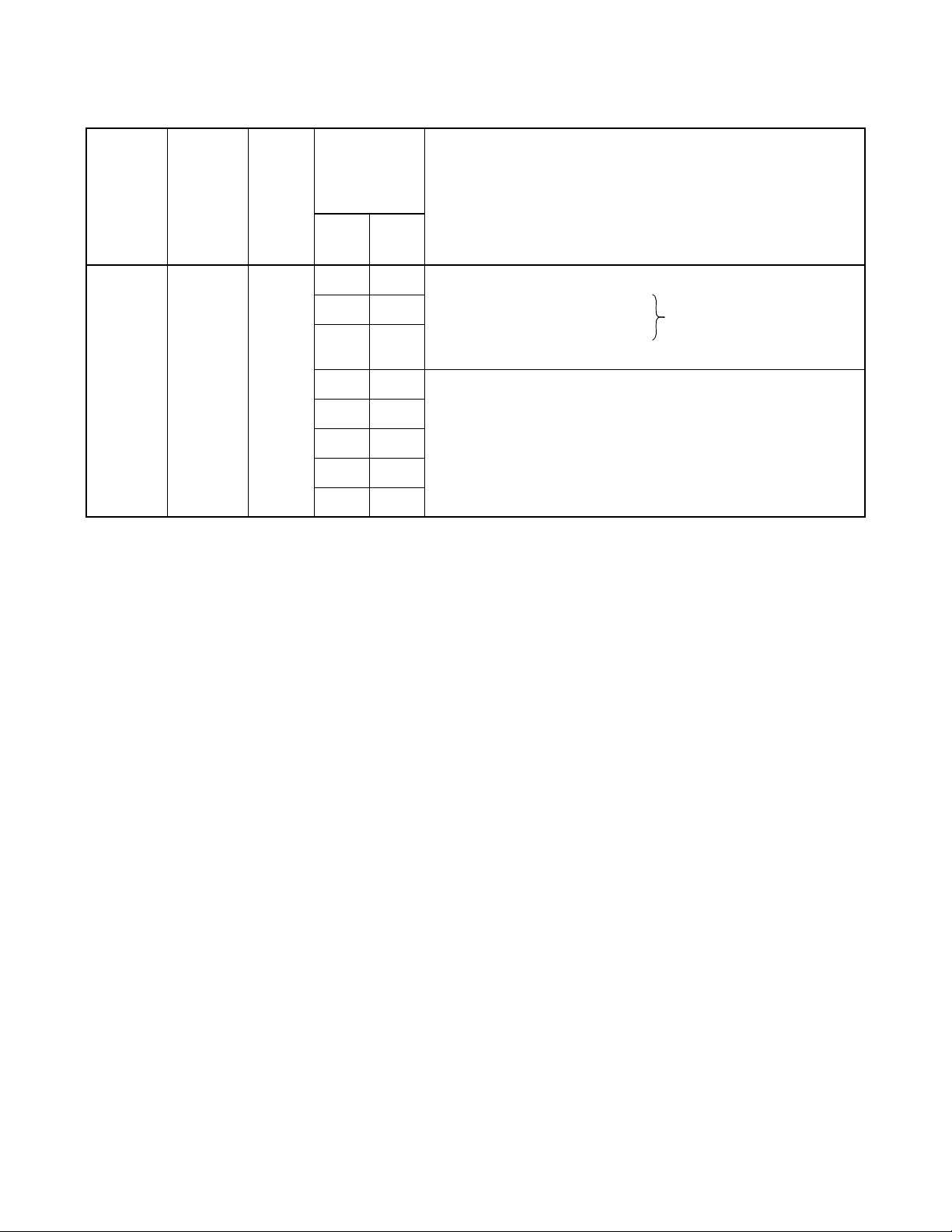
COMMANDS
ASYD
System Data Assign Table (3)
SYSTEM
DAT A
TYPE
(SYS)
SYSTEM
DATA
INDEX
(INDEX)
0 – 255
DAT A
(DATA)
00– FF
(Hex)
BIT
CORRE-
SPONDING
DATA SYSTEM DATA CONTENTS
DATA
0/1
BIT
b
b
b
Designation of the initial mode of the card reader
0
000: PB Sender 100
1
001: LP Command : Not used
010: – 111
2
011: Data channel
~
315
0b
0b
0b
0b
0b
3
4
5
6
7
Not used
CHAPTER 4 ND-70895 (E)
Page 52
Revision 1.0
Page 63

DFLN: Display of Location Free Numbering
29. Functions
This command is used to check the assigned data of Location Free Numbering Service. When this
command is activated, the assigned data are displayed on a basis of each designated stat ion number.
30. Precaution
The data to be displayed by this command are those assigned from the User Application Processor (UAP)
and thus they cannot be assi gned by a command.
31. Parameters
[Input Parameters]
F : Function Kind (0/1)
LSTN : Logical Station Number (ID-No. Max. 5 digits)
TN : Tenant Number
PSTN : Physical Station Number (Station Number)
[Display Parameters]
RSC : Route Restriction Class
SFC : Service Feature Restriction Class
DC : Digit Code
COMMANDS
DFLN
Note 1
Note 2
Note 2
Note 1:
Note 2:
This parameter is to be entered/displayed only when F = 0.
These parameters are to be entered/displayed only when F = 1.
32. Related Commands
–
ND-70895 (E) CHAPTER 4
Page 53
Revision 1.0
Page 64

COMMANDS
ASYDN
ASYDN: Assignment of System Data in NDM
33. Function
This command is used to assign system data 1 and 2.
34. Precautions
1. This section only explains about ASYDN command for OAI system.
2. For more details of ASYDN command, see the “Office Data Specification.”
35. Parameters
Refer to the following page.
CHAPTER 4 ND-70895 (E)
Page 54
Revision 1.0
Page 65

COMMANDS
ASYDN
SYSTEM
DAT A
TYPE
(SYS)
1
SYSTEM
DATA
INDEX
(INDEX)
0 – 1535
514 01
533
DAT A
(DATA)
00 – FF
(Hex)
BIT
CORRESPONDING
DATA
DATA
0/1
BIT
b
b
b
b
b
b
b
b
b
b
b
b
b
b
b
0
1
2
3
4
5
6
7
0
1
2
3
4
5
6
SYSTEM DATA CONTENTS (MDATA)
Network Data Memory (NDM) usage. Assign
data “1 (the memory block is used)” for the
corresponding memory block.
bit Memory Block
Memory Block #0
b
0
Memory Block #1
b
1
Memory Block #2
b
2
Memory Block #3
b
3
Memory Block #4
b
4
Set up Fusion Point Code (FPC) of Node which
basic VNDM is mounted on. (1~253)
Note: OAI/ACD is available in used.
VNDM = Variable Network Data
Memory
Note 1:
Note 2:
b
7
864 b
870
3
b
0
b
1
b
2
b
3
b
4
b
5
b
6
b
7
Multiple IPs 0/1 = Out/In Service Note 1
FLF Fusion Service
0/1 = Invalid/Valid Note 2
Not used
When the all Fusion nodes in the net work are used for “MULTIPLE IPs”, this data may be assigned using
ASYDN.
Available since the Series 7400 (Release 8) software.
ND-70895 (E) CHAPTER 4
Page 55
Revision 1.0
Page 66

COMMANDS
ASYDL
ASYDL: Assignment of System Data into Local DM (LDM)
36. Function
This command is used to assign and change system data for OAI activated via FCCS.
37. Precautions
ASYDL command is comprised with System Data-1, INDEX 512-1535.
This section only explains about ASYDL command for OAI System.
38. Parameters
Refer to the following pages.
CHAPTER 4 ND-70895 (E)
Page 56
Revision 1.0
Page 67
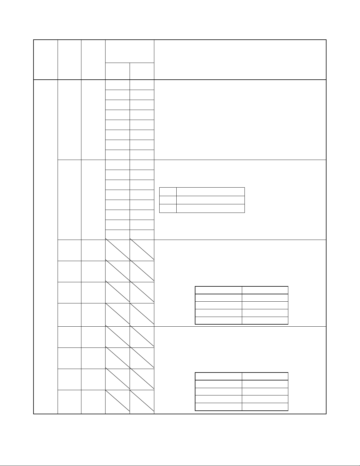
COMMANDS
ASYDL
SYSTEM
DATA
TYPE
(SYS)
1
SYSTEM
DAT A
INDEX
(INDEX)
512-1535
512
513 01
515
516
517
518
DATA
(DATA)
00 – FF
(Hex)
BIT
CORRESPONDING
DAT A
DATA
0/1
BIT
b
b
b
b
b
b
b
b
b
b
b
b
b
b
b
b
0
1
2
3
4
5
6
7
0
1
2
3
4
5
6
7
SYSTEM DATA CONTENTS
Fusion Point Code (FPC) of self node in hexadecimal .
FPC 1-253 (01 He x-FD Hex)
Note: After assigning/changing the FPC, System Initialization (Non-
Load Initializat i on) i s required.
Local Data Memory (LDM) usage. Assign data “1 (the memory block
is used)” for the corresponding memory block.
bit Memory Block
Memory Block #0
b
0
Memory Block #1
b
1
Memory Block #2
b
2
IP Address (Hex) for PBX over External LAN
Note: This data is valid when the PBX is connected to the external
PC LAN.
When 172.16.253.0 (default IP address) for the PBX is used, this data
setting is not necessary.
Example:
IP Address : 133.206.8.1
INDEX Set Hex
515 85
516 CE
517 08
518 01
519
520
521
522
Subnet Mask (Hex) for PBX over External LAN
Note: This data is valid when the PBX is connected to the external
PC LAN.
When 172.16.253.0 (default IP address) for the PBX is used, this data
setting is not necessary.
Example:
Subnet Mask : 255.255.0.0
INDEX Set Hex
519 FF
520 FF
521 00
522 00
ND-70895 (E) CHAPTER 4
Page 57
Revision 1.0
Page 68

COMMANDS
ASYDL
SYSTEM
DATA
TYPE
(SYS)
1
SYSTEM
DAT A
INDEX
(INDEX)
512-1535
523
524
525
526
DATA
(DATA)
00 – FF
(Hex)
BIT
CORRESPONDING
DAT A
DATA
0/1
BIT
SYSTEM DATA CONTENTS
Default Gateway Address of External LAN
Gateway Address (IP address of Router) of Network connecting PBX.
Note: This data is valid when the PBX is connected to the external
PC LAN.
In the case of no Network Gateway, assignment data is 00 Hex.
in Index 523 through 526.
Example:
Default Gate way Address : 133.206.8.254
INDEX Set Hex
523 85
524 CE
525 08
526 FE
CHAPTER 4 ND-70895 (E)
Page 58
Revision 1.0
Page 69

CHAPTER 5 OFFICE DATA DESIGN
1. General
This chapter explains th e procedure for setti ng the office dat a require d in the NEAX2400 IMX OAI System. As
for the offi ce data sett ing procedure of the NEAX 2400 IMX Sy stem itself, re fer to the Sy stem Data D esign
Manual.
The description of this Cha pter consists of the following contents.
• Procedure for Setting Basic Office Data for OAI System
This section explains the procedure for setting the basic office data of the OAI system.
• Procedure fo r Setting Office Data for OAI Services
This section explains the procedure for setting the office data of the main services of the OAI system.
ND-70895 (E) CHAPTER 5
Page 59
Revision 1.0
Page 70

OFFICE DATA DESIGN
Procedure for Setting Basic Office Data for OAI System
2. Procedure for Setting Basic Office Data for OAI System
The procedure for setting the office data for OAI system is explained in the following.
2.1 Data for OAI System
1. ASYD/ASYDL
ASYD-SYS1 INDEX31 - b0 ~ 3 : CM mounting capacity (Normally Assign “04”.)
INDEX79 - b6 = 0 (OAI serv ice is in service )
INDEX207 - b0 (IP in system 0), b1 (IP in system 1)
Assign “1” to the corresponding bit for the IP accommodation.
INDEX241 - b2 = 1 (Call Processing Event Notification)
INDEX241 - b3 = 1 (D etails of SCF Er ro r Notification)
ASYDL-SYS1 INDEX513 : 01 Hex (LDM usage)
INDEX515~518 : IP address (Hex) for PBX over External LAN
INDEX519~522 : Subnet Mask (Hex) for PBX over External LAN
INDEX523~526 : Default Gateway Address for External LAN
(This data is required when the Host is connected via gateway)
INDEX864 - b0 = 1 (Built-in IP is provided)
INDEX864 b1 : Output the system message (4-R) when TCP-IP is norma ll y
disconnected.
0/1 = Effective/Ineffective
2. ARNP (Reverse Numbering Plan Data)
If necessary, assign the self office code when assigning office information within a message of
the facility
CHAPTER 5 ND-70895 (E)
Page 60
Revision 1.0
Page 71

2.2 Data for OAI Terminal
OFFICE DATA DESIGN
Procedure for Setting Basic Office Data for OAI System
In the case of D
term
1. ASDT (In the c ase of Busine ss; Stati on Data ), AASP (In t he ca se of Hotel sys tem; St atio n Data)
Assign station data
Voice Port: TEC12 Data Port: TEC13
(Normal settin g f or others)
Note 1:
For ASDT/AASP command, refer to the Command Manual of the NEAX2400 IMX.
2. AKYD (D
term
Key Data)
Assign the function key data of D
term
Assign FKY34–47 to any positions of FKY 1–16.
(Normal settin g f or others)
3. AOKC (OAI Key Code Data)
Assign the OAI key code data
OAI key code 1 ~ 14 respectively corresponds to FKY34 ~ 47 of AKYD
4. AOAC (OAI Access Code Data)
If necessary, assign OAI acces s code data when using “OAI key + Acces s code” system to act iv ate
the application by MSF/TMF
In the case of Single-Line Telephone
Note 1
1. ASYD (System Data)
Assign OAI Host Computer Respond Wait Timer
2. ANPD (Numbering Plan Data)
Assign the minimum neces sary number of digits for OA I Dial Number Con tinuous T rans fer Code
Note 2
3. ASPA (Special Access Code Data)
Assign the OAI Dial Number Continuous T r ansfer Access Code
SSCA: 69 (OAI Dial Number Continuous Transfer)
NND : Necessary Number of Digits of OAI access code (Max. 3 digits)
Note 2:
For ANPD command, refer to the Command Manual of the NEAX2400 IMX.
4. AOAC (OAI Access Code Data)
Assign OAI access code data
ND-70895 (E) CHAPTER 5
Page 61
Revision 1.0
Page 72

OFFICE DATA DESIGN
Procedure for Setting Office Data for OAI Services
3. Procedure for Setting Office Data for OAI Services
This section explains the outline, using conditions, and office data setting procedure of the main OAI service
functions.
3.1 Switch Control Facility (SCF)
3.1.1 Functional Outline
Note:
The SCF is th e facility tha t executes, from the Applic ation Progr am (AP), such contro l operation s as
connections/disconnections between NEAX2400 IMX-accommodate terminal (D
between a D
term
and a C.O. Line Outgoing/Incoming Trunk, etc. The SCF has several functions (FN),
term
) and another,
and explanatio ns will be giv en in the follo wing about “Basic Conn ecting Function (FN = 1) – Make Cal l
(Automatic Answer)” whic h is one of the several functions.
The basic connection fun ction is a function whi ch auto matically set a ter minal into an outgoi ng connection
status. Responding to a connection request from the AP, both the calling terminal number and the call
destination number can be designated.
Station Group
NEAX2400 IMX
CHAPTER 5 ND-70895 (E)
Page 62
Revision 1.0
Host Computer
[Application Program (AP]
Page 73

OFFICE DATA DESIGN
Procedure for Setting Office Data for OAI Serv ic es
3.1.2 Using Conditions
1. Normal and abnormal operating sequences pertaining to the basic connection of the SCF are as
described below.
[Normal Sequence]
Destination Terminal Calling Terminal NEAX2400 Computer (AP)
SCF Activated
Terminal Check
Return Result
Connection
<Zip tone>
<Zip tone>
(a) Upon receiving SCF start request from the AP, the NEAX2400 IMX judges the status (idle,
busy, makebusy, etc.) of the designated ca lling terminal and destination term inal.
(b) If the calling terminal and the destination terminal are idle, the NEAX2400 IMX sends out
Return Result to the AP, and places th e call ing termin al int o an outgoin g connect ion stat us and
the destination terminal into ringing status.
These are the basic functions.
(c) When the destination terminal designated from the AP is a terminal in the NEAX2400 IMX
and automatic answer is designated as the answer type, both the calling and destination
terminals can be placed into speech status immediately from the status cited in (b) (After zip
tone has been sent to both terminals, the terminals are placed into speech status.).
Note that this service function is valid only when the destination terminal is in line selection
wait status and also automatic answer is designated as the answer type. In other words, if the
destination terminal is in a status other than line selection wait status, the call is to be answered
manually. Further, this service function is valid only when the des ti nation terminal is a station
term
(D
: Voice) among the SCF Make Call designations. In other words, if the call destination
is a trunk, this service function does not work.
ND-70895 (E) CHAPTER 5
Page 63
Revision 1.0
Page 74
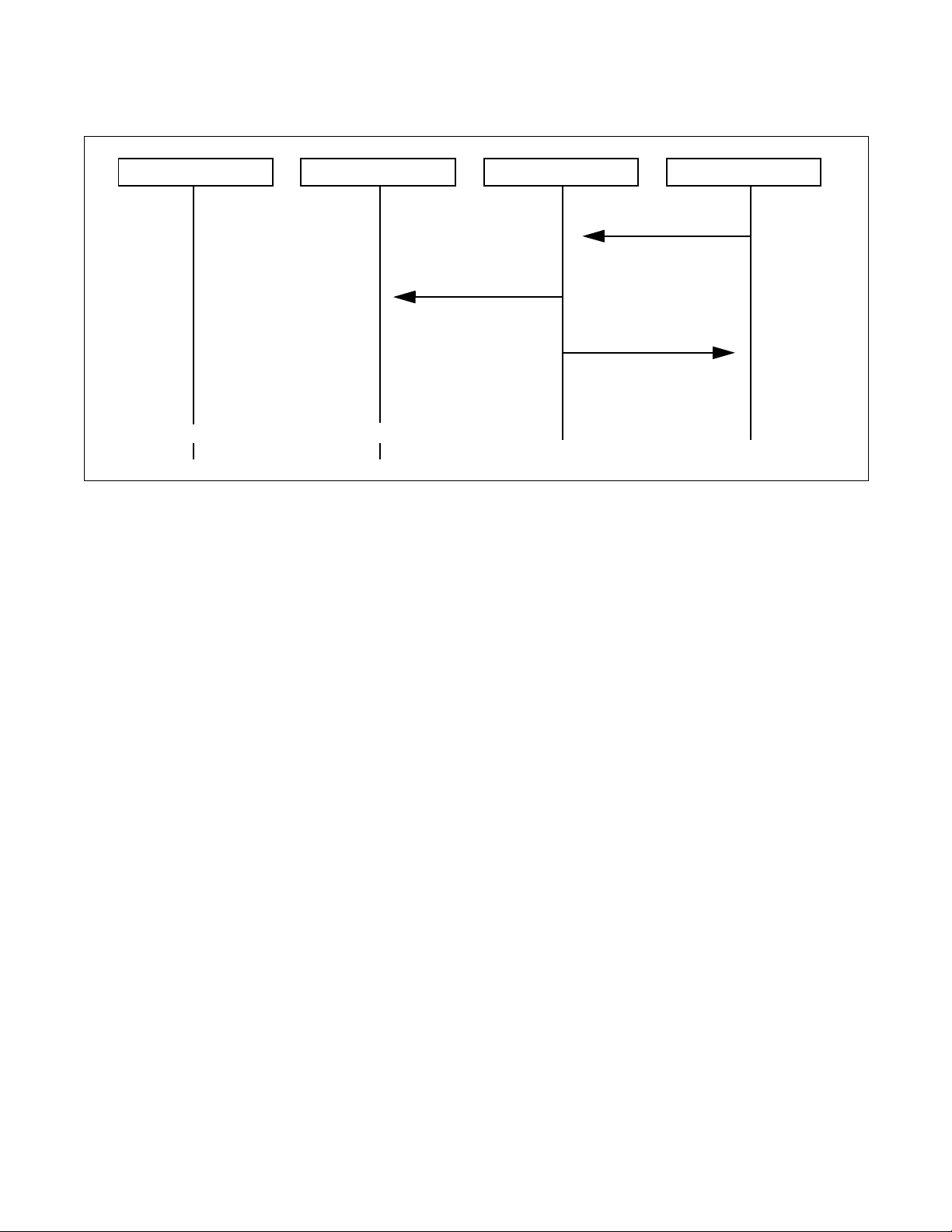
OFFICE DATA DESIGN
Procedure for Setting Office Data for OAI Services
[Abnormal Sequence]
Destination Terminal Calling Terminal NEAX2400 Computer (AP)
SCF Activated
Terminal Check
Return Error
<Idle>
<Busy>
(a) Upon receiving SCF start request from the AP, the NEAX2400 IMX judges the status (idle, busy,
makebusy, etc.) of the designated ca lling terminal an d destination termi nal.
(b) If th e calling termin al and the destination terminal are in a status other tha n idle, the NEAX2 400
IMX sends out Return Error to the AP.
2. Only digital multifunction telephone ( D
term
Series E) can be designated as a calling terminal.
CHAPTER 5 ND-70895 (E)
Page 64
Revision 1.0
Page 75

3.1.3 Data Programming
Assignment
1. ASYD (System Data)
SYS1
INDEX 79
b6: 0 (OAI service is available)
OFFICE DATA DESIGN
Procedure for Setting Office Data for OAI Serv ic es
2. AKYD (D
term
Key Data)
Restrict a call origination from the prime line of the terminal of which answer type is
designated as automatic ans we r
S: Outgoing call from a prime line (0/1)
0/1: Allowed/Restricted
Deletion
1. AKYD (D
term
Key Data)
Cancel restriction on a call origination from the prime line of the terminal of which answer
type is designated as automatic answer
S: Outgoing call from a prime line (0/1)
0/1: Allowed/Restricted
2. ASYD (System Data)
SYS1
INDEX 79
b6: 1 (OAI service is not available)
ND-70895 (E) CHAPTER 5
Page 65
Revision 1.0
Page 76

OFFICE DATA DESIGN
Procedure for Setting Office Data for OAI Services
3.2 Call ID Notification (SMFN for ISDN)
3.2.1 Functional Outline
This Call ID Notification function is an enhancement of both the Call Termination Notifi cat ion and the
Answer Notifi cation among Call Status Monitor Fa ci lity Notifi ca tion functions of the OAI s ystem, and
provides the User’s Application Processor for External Computer (UAP) with the caller’s information
when call termination is to be notified about an incoming call from the Integrated Services Digital
Network (ISD N) concern ed. Likewise, w hen the call ed terminal has answer ed an inco ming call, this
function also provides the UAP with the ISDN caller’s information.
Station Group
term
D
NEAX2400 IMX
Single-Line Telephone
3.2.2 Using Conditions
1. Only when a call has terminated from the ISDN and when the call has been answered, SMFN
message is sent out with the caller’s information added. Note, however, that caller’s information
may not be added to the message depending on the restrictive conditions pertaining to the caller
notification of the ISDN.
2. The number of digits for ISDN caller’s information is maximum 33 for the caller’s number and
maximum 20 for call sub-address.
SET-UP Signal
ISDN
SMFN
UAP
3. The SMFR cannot monitor ISDN termin al, and thus when a call has termi nated to an ISDN terminal
and the call has been answered, SMFN message is not sent out .
CHAPTER 5 ND-70895 (E)
Page 66
Revision 1.0
Page 77

4. When an incoming call terminates from ISDN network, ISDN caller’s number information
(subscriber’s number and sub-address) is provided from the central office in the following format.
D
D
C
C
2
1
Subscriber number is maximum 33 digits, and the sub-address is maximum 20 digits, and they are
separated by the separator “*” (OBH).
3.2.3 Data Programming
1. Assignment
ASYD (System Data)
SYS1
INDEX 79
b6: 0 (OAI service is not available)
INDEX 24 1
b2: 1 (OAI Call Status Monitor Facility Notification is not in service)
Procedure for Setting Office Data for OAI Serv ic es
ISDN Caller’s Number Information
D
C
n–1
OFFICE DATA DESIGN
D
C
≤n≤
1
54
n
2. Deletion
ASYD (System Data)
SYS1
INDEX 79
b6: 1 (OAI service is not available)
INDEX 24 1
b2: 0 (OAI Call Status Monitor Facility Notification is not in service)
ND-70895 (E) CHAPTER 5
Page 67
Revision 1.0
Page 78
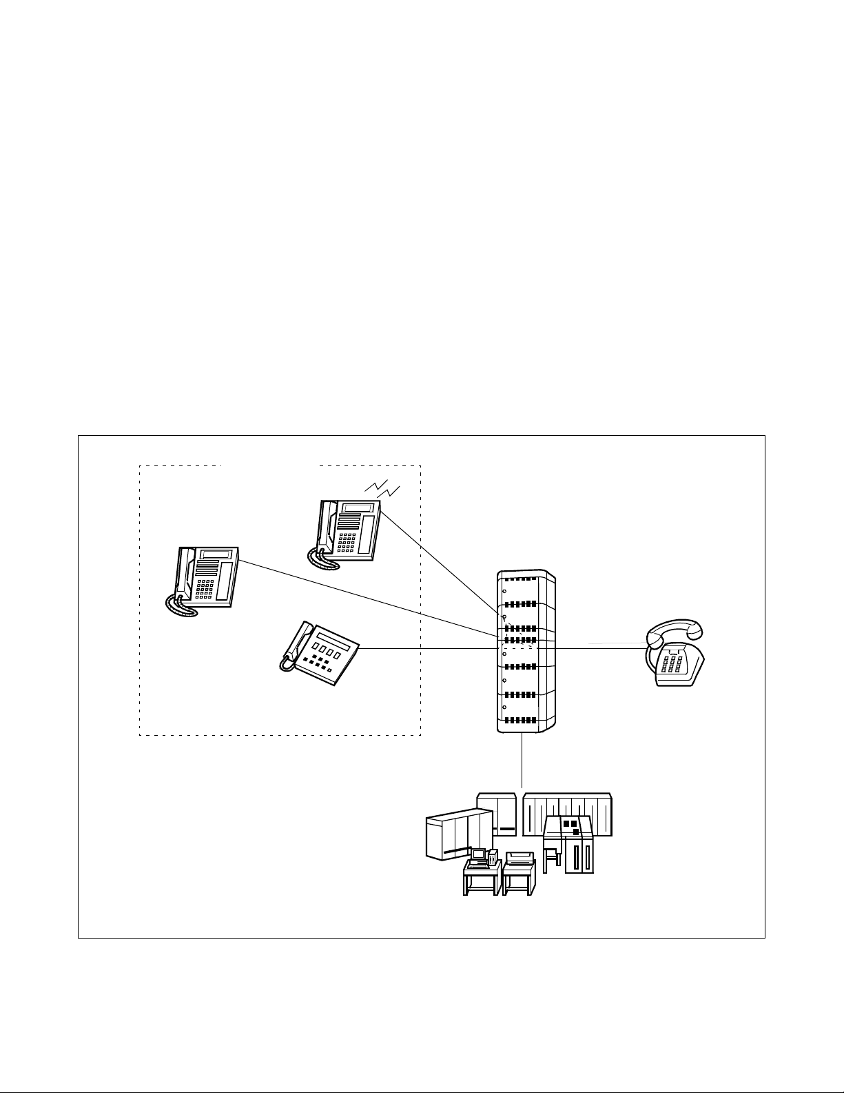
OFFICE DATA DESIGN
Procedure for Setting Office Data for OAI Services
3.3 MWL Control (SSF) STEP-1
3.3.1 Functional Outline
This function allows the Application Program (AP) to provide a single-line telephone equipped with
Message Waiting Lamp (MWL) or a D
term
with the following Message Waiting (MW) services by the
OAI Service Set Facility (SSF).
1. MW Setting (Turning MW Lamp On)
2. MW Resetting (Flashing MW Lamp)
3. MW CANCEL (Turning MW Lamp Off)
4. LCD Display on each MW type
Display con tents: Message Waiting (MW)
Voice Mail Module (VMM)
Text Mail Module (TMM)
Facsimile Mail Module (FMM)
Station Group
NEAX2400 IMX
term
(D
)
term
(D
)
Single-Line Telephone
(W/MWL)
CHAPTER 5 ND-70895 (E)
Page 68
Revision 1.0
Host Computer
[Applic ation Program (AP)]
Page 79
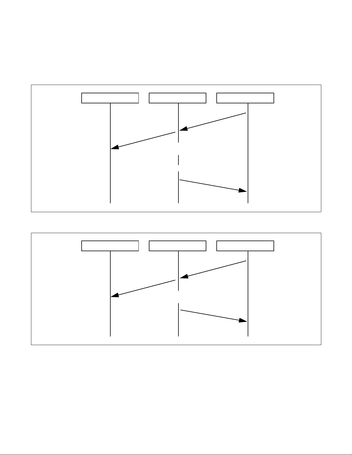
3.3.2 Using Conditions
1. Normal and abnormal operating sequences pertaining to the basic connection of the SSFR are as
described below.
[Normal Sequence]
OFFICE DATA DESIGN
Procedure for Setting Office Data for OAI Serv ic es
Terminal (D
[Abnormal Sequence]
Terminal (D
term
) NEAX2400 IMX Computer (AP)
SSFR Activated
Received Information
Analysis
Service Set/Cancel
Return Result
term
) NEAX2400 IMX Computer (AP)
SSFR Activated
Received Information
Analysis
Return Result
ND-70895 (E) CHAPTER 5
Page 69
Revision 1.0
Page 80

OFFICE DATA DESIGN
Procedure for Setting Office Data for OAI Services
2. This service cannot be use d simultaneously wit h other MW control servi ces (VMM/MCI: Message
Center Interface/Message Waiting from Station, ATTCON and MAT).
3. The conditions for th e telephone that controls MW are as follows.
• MW can be serviced only on a telephone equipped wi t h MW lamp functi on .
• On a single-line telephone and/or D
• On a single-line telephone, MW lamp flashing cannot be controlled (ON/OFF only).
• MW lamp on/off/flashing, and LCD display can be controlled on a D
available only on a D
term
•D
can control only lamp flashing (LCD display cannot be controlled).
term
equipped with the indicator.)
4. In the case of MW ser vice by SSFR (Co nf irm- type <Computer → NEAX> Performer facility), the
same kinds of display (MW, VMS) as those of MCI (Message Center Interface) are poss ibl e.
5. In the case of deletion of all the station data and all the type data, only the same data as those of
MCI are dele ted. MW service information for stations from the OAI Terminal Control Facility
(TCF) are not de le te d .
term
, MW lamp display position is fixed.
term
. (MW indication is
6. In the case of MW service by SSFR, lamp on/flashing/off is immediately indicated at the time of
one station control. In the case of deletion of all the station data and all the type data, a delay time
of maximum 196 seconds generates until the status of the terminal changes actually.
7. The system configuration for implem enting this service is as illustrated below.
Terminal NEAX2400 IMX
term
(D
)
Single-Line
Telephone
with MWL
DLC
LC
TSW
OAI
CPU IP
Computer
SSFR
Application
Program
(AP)
CHAPTER 5 ND-70895 (E)
Page 70
Revision 1.0
Page 81

3.3.3 Data Programming
Assignment
1. ASYD (System Data)
SYS1
INDEX 77
b2: 0 (MW Lamp Refresh C ontrol is in service)
INDEX 17 9
b6: 0 (OAI services are provided)
2. ARPC (Remote Point Code for Centralized Service)
For providing centralized services at the Message Center within a No. 7 CCIS Network,
assign the point codes for the remote offices belonging to the main office
CSN: Centralized Service Item No. (1 ~ 7)
CNT: Number of Remote Office Point Codes (1 ~ 32)
RPC: Remote Office Point Code (1 ~ 16367)
Deletion
OFFICE DATA DESIGN
Procedure for Setting Office Data for OAI Serv ic es
1: Message Center
1. ARPC (Remote Point Code for Centralized Service)
Delete the point codes of the remote offices belonging to the main office
2. ASYD (System Data)
SYS1
INDEX 77
b2: 1 (MW Lamp Refresh Control is not in service)
INDEX 17 9
b6: 1 (OAI services are not provided)
ND-70895 (E) CHAPTER 5
Page 71
Revision 1.0
Page 82

OFFICE DATA DESIGN
Procedure for Setting Office Data for OAI Services
3.4 TCP/IP Address (Assignment from MAT)
3.4.1 Functional Outline
In an OAI sy stem to be connected with the host computer via t he Ethernet, this function allows use of
TCP/IP port with the self internet address (TCP/IP address) of the NEAX2400 IMX assigned from the
MAT.
Also, whether system message “4-R” (IOC card for the host computer is faulty) is to be output or not
when the connection with the host co mputer has been normall y discon nected can be selec ted by switch
setting on t he Interface Process or (IP).
3.4.2 Using Conditions
1. Due to the hardwar e li mi ta tion, only one physical TCP/IP por t can be accommodated per system.
2. Basic Value of TCP/IP Address is “172.16.253.0”.
3. The TCP/IP addresses (A, B, C, D) that cannot be used by this function are as follows.
Classes A, B, and C can be used. Note that Host Number = 0 cannot be used. (Conditions [1] ~[3].
Classes D and E cannot be used. (Condition [4])
<
Class A: [1] 0 A 127 → A, 0, 0, 0
Class B: [2] 128 A 191 → A, B, 0, 0 (0 B 255)
Class C: [3] 192 A 223 → A, B, C, 0 (0 B 255, 0 C 255)
Class D, E: [4] 244 A → A, B, C, D (0 B 255, 0 C 255, 0 D 255)
<
< < < <
< < < < < <
< < < < < < <
4. System message “4-R” out put can be s topped by swi tch sett ing on the S ystem Data onl y when TCP
connection has been disconnected (Normal) (ERRK=01).
CHAPTER 5 ND-70895 (E)
Page 72
Revision 1.0
Page 83

3.4.3 Data Programming
TCP/IP Address Assignment
1. Assignment
ASYDL (Sys tem Data (LDM))
Assign TCP/IP address
SYS1
INDEX 515 ~ 518
2. Deletion
ASYDL (Sys tem Data (LDM))
Delete TCP/IP address
SYS1
INDEX 515 ~ 518
Stopping the system message of “4-R”
1. Assignment
ASYDL (Sys tem Data (LDM))
SYS1
INDEX 86 4
b1 = 1 (The system message (4-R) is not output when TCP/IP connection is normally
OFFICE DATA DESIGN
Procedure for Setting Office Data for OAI Serv ic es
disconnected.)
2. Deletion
ASYDL (Sys tem Data (LDM))
SYS1
INDEX 86 4
b1 = 0
ND-70895 (E) CHAPTER 5
Page 73
Revision 1.0
Page 84

OFFICE DATA DESIGN
Procedure for Setting Office Data for OAI Services
3.5 Name Display
3.5.1 Functional Outline
This service is for displaying inf ormat ion (user’s name, station number, etc.) on the LCD of D
1. Catch internal call
2. Catch Forwar ding Call from Call F orw arding Busy Line, Call Forw arding Abs ent, Call Forw arding
Don’t Answer, Station Hunting, or etc..
3.5.2 Using Conditions
1. Maximum 16 digits of user’s information can be displayed on LCD according to i nternal numbers.
2. What is available for this service to display, is alphabet, digit, sign or etc..
3. For administr ating user’s information clearly, it is not av aila ble to use both “Name Displ ay Service”
which is assigned by ANDD command and “OAI Service” at same time.
4. It is not a v ailab le to us e both 8- digit Di splay Ser vice and 16-digit Display Ser vice at same time. For
changing from 8-digit Display Service to 16-digit Display Service, can be changed by using
“System Da ta”.
5. There are limitations below for 16-digit Display Service.
• User’s information can not be displayed on the top line of LCD.
• User’s information is displayed from the left side of bottom line and if the information is less than
16-digit, the rest of frames will be blank.
term
.
term
• It is not able to set mu lti-line on this D
.
6. There is a limitation below for 8-digit Display Service.
• User’s information is displayed from the middle of top line and if the information is less than 8
digits, the rest of frames will be blank. And the bottom line will display the clock.
7. If the user’s information is not assigned, normally station number will be displayed.
8. There is no guarante e f or the user’s information since you change from 16-digit Display Service to
8-digit Display Service.
term
9. The service will be ef f ective, if either of calling party or call ed part y has D
which has the LCD.
CHAPTER 5 ND-70895 (E)
Page 74
Revision 1.0
Page 85

Procedure for Setting Office Data for OAI Serv ic es
3.5.3 Data Programming (Set up from User’s Application)
1. Assignment
ASYD
SYS1
INDEX31: 04: mount capacity of Common Memory (CM) 4Mbyte
INDEX78
b0 = 1 (Intermediate Station Number Display is in service)
b1 = 1 (Service Assortment Display is in service)
b3: Dial Number Display 0/1: Out/In service
b5 = 1 (Name Display Service is in service)
INDEX79
b5: Expande d Name Display (d isplaying 16- digit) 0/1: Out/ In service
b6 = 0 (OAI Service is in service)
INDEX241
b1: Name Display 0/1: 8-digit/16-digit
OFFICE DATA DESIGN
2. Deletion
ASYD
SYS1
INDEX78
b0: Intermed iate Station Nu m b er Display 0/1: Out/In service
b1: Service As sortment Displ ay 0/1: Out/In service
b3: Dial Number Display 0/1: Out/In service
b5 = 0 (Name Display service is Out)
INDEX79
b5: Expande d Name Display (d isplaying 16- digit) 0/1: Out/ In service
b6 = 1 (OAI Service is Out)
INDEX241
b1 = 0 (Name Display is displaying 8-digit)
ND-70895 (E) CHAPTER 5
Page 75
Revision 1.0
Page 86

OFFICE DATA DESIGN
Procedure for Setting Office Data for OAI Services
3.6 Inter Node Name Display
3.6.1 Functional Outline
Name Display Service is available between the network.
Name Displa y Service means for the facility of displaying le tters (alphabet and etc.) on LCD of the
term
D
.
Catching call from other internal line
3.6.2 Using Conditions
1. When Calling party is calling Called party, the LCD of Calling party will display Called party’s
name information by the internal number.
2. If there is no information of Calling p arty or Calle d party , only the nu mber of Callin g party or Cal led
party’s will be displayed.
3. When there are both 8-digit and 16- digit of Inter Node Name Display Se rvice in same Node, Calling
party/Called party’s name will be shown as bel ow.
Inter Node Name Display
Service
Calling Party → Called party
16-digit
8-digit
8-digit
16-digit
→
→
8-digit 16-digit on Center Line
→
16-digit 8-digit on Top Line
→
16-digit → 8-digit 8-digit on Top Line 8-digit on Top Line
8-digit → 16-digit 16-digit on Center Line 8-digit on Center Line
4. When Name Display Service is set up for 16-digit , it will be unable to set up multi -line a t the D
5. When Calling party reaches CCIS call to Called party by using D
Called party will di splay the Sub-L in e name of Calling party. (Only for 8-digi t)
6. The Name Display of Called party indicates prime line only for Both of 8-digit and 16-digit.
7. What is available to display for this se rvice, are alphabet, fi gu re, sign and etc... .
8. Assign the Name Information Data, based on each D
available on the user’s application.
9. The route which is set up Inter Node Display Service and the route which is not set up Inter Node
Display Service should be separated from each other.
Display of Calling party’s name Display of Called party’s name
8-digit on Top Line
(right side of 8-digit will be blank)
(First 8-digit will be displayed)
term
LEN, by using the Free Location Facility
(First 8-digit will be displayed)
16-digit on Center Line
(right side of 8-digit will be blank)
term
Sub-Line, the display of
term
.
10. Even Dial Number Displa y Service is ac tiv ate, th e dial number w on’t be displayed betwe en the Inter
Node.
CHAPTER 5 ND-70895 (E)
Page 76
Revision 1.0
Page 87

OFFICE DATA DESIGN
Procedure for Setting Office Data for OAI Serv ic es
11. The objected terminal of Name Display Service is only D
term
which has LCD.
12. “Office Code” + “Station Number” is normally displayed. However, when use of a logical number
is specified, only the logical number without an office code is displayed. (ONE CCIS network is
assigned only one logical number.)
13. When a call has been transferred by “Call Forwarding All Outside Line Call” or “Call ForwardingBusy Outside Line Call”, the LCD of Calling Party’s D
term
will displa y “Name Informati on” of
Called party, instead of dialed number.
14. When you call t o a party by the wa y of a party which do esn’t ha ve Inter No de Name Display Servic e
in CCIS network, or the other Node of CCIS network, the Name Display Service will not serve.
A Office
(1)
(2)
CCIS
CCIS
C Office
CCIS
D Office
(Name Display
- System - CCIS is
not serviced)
CCIS
B Office
CCIS
E Office
In the case of (1): Name Display is serviced.
In the case of (2): Name Display is not serviced.
In the case of (3): Name Display is not serviced.
15. This service can not be used in conjunction with ISDN Information Transfer-CCIS Service.
16. Those below are the Inter Node Services which are able to serve Inter Node Name Display.
•Voice Call
• Inter Node Call Forwardi ng All Call
• Inter Node Call Forwarding Bu sy Line
• Inter Node Call Forwarding No Answer
• Inter Node Camp On (Only for calling)
• Message Reminder (Only for outgoing)
17. Those below are the Self Node Services including CCIS Trunk which are able serve Inter Node
Name Display.
•Call Pick Up
• Ring in g for Call Hold
• Answering for call park
• Call waiting
• Catching call from UCD Queuing
18. For the terminal which is able to serve Inter Node Display Service, please see the Item of Name
Display Service.
ND-70895 (E) CHAPTER 5
Page 77
Revision 1.0
Page 88

OFFICE DATA DESIGN
Procedure for Setting Office Data for OAI Services
3.6.3 Data Programming (Set up from User’s Application)
Assignment
Those below are explanation of the Assignment according to Name Information which is set up
from User’s Application.
1. ASYD
SYS1
INDEX 78
b5 = 1 (Name Display Service is in service)
b3: Dial Number Display 0/1: Out/In service
INDEX 79
b6 = 0 (OAI Service is in service)
INDEX 24 1
b1: Name Display 0/1: 8-digit/16-digit displaying
2. Route Class Data (ARTD)
Change the Route Class Data of CCIS Trunk
Busy Line Service (BT): 1 (Active)
Number Display Designation (DPLY): 1(Called Party Number Display)
ISDN Output Information (CI): 0 (Existing)
Inter Node D is play Service (IN D ): 1 (In service)
Deletion
1. Route Class Data (ARTD)
Delete the Route Class Data of CCIS Trunk
Busy Line Service (BT): 0/1 (Out/In Service)
Number Display Designation (DPLY): 0/1(-/Called Party Number Display)
ISDN Output Information (CI): 0 ~ 15
Inter Node Display Service (I N D ) : 0 (O ut)
2. ASYD
SYS1
INDEX 78
b5: Name Display Service 0/1: Out/In servi ce
b3: Dial Number Display 0/1: Out/In service
INDEX 79
b6 = 1 (OAI Service is not in service)
INDEX 24 1
b1 = 0 (Name Display 8-digit)
CHAPTER 5 ND-70895 (E)
Page 78
Revision 1.0
Page 89
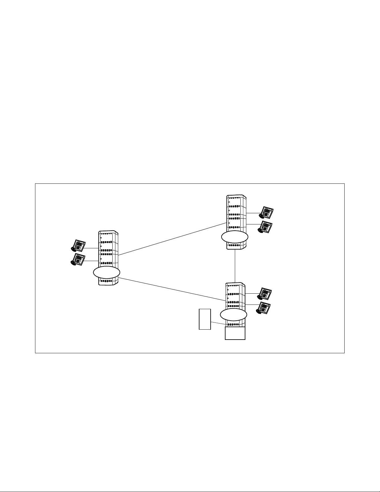
OFFICE DATA DESIGN
Procedure for Setting Office Data for OAI Serv ic es
3.7 OAI Fusion
Main advantages of OAI Fusion fall down into the following. OAI Fusion systems can be divided into the
following two types:
• OAI Terminal Anywhere
• Multiple IPs
3.7.1 OAI Terminal Anywhere
3.7.1.1 Functional Outline
In this configuration (OAI T erminal Anywhere), the OAI terminal can be installed in any Fusion node
whether the node has the IP or not (those OAI terminals in m ultiple nodes are controlled by one IP).
In other words, the facilities in multiple nodes (any Fusion node whether the node has the IP or not)
are controlled by one IP. (“F acilit y” which c an be us ed throug h the Fusion Net work v a ries in “the OAI
application”.)
Node A
Node B
OAI Terminals
FACILITY
3.7.1.2 Using Conditions
(a) The Node that accommodates the IP is one node only in a Fusion network.
(b) T ele phone Numbe r (m ax. 5 di gits ) is used f or the stat io n number typ e to a ctivated OAI syst em
through Fusion network.
FCCS
FCCS
UAP
FCCS
FACILITY
FACILITY
IP
Node C
OAI Terminals
OAI Terminals
(c) Logic al Route is used for the route type to activate OAI system through Fusion network .
ND-70895 (E) CHAPTER 5
Page 79
Revision 1.0
Page 90

OFFICE DATA DESIGN
Procedure for Setting Office Data for OAI Services
(d) The node that accommodates t he IP must be initial iz ed when all the oth er nodes are in on-line
mode.
(e) The User’s Application (UAP) must be booted up after the confirmation of the establishment
of the Fusion link.
(f) When you add a node/nodes t o the net work, you ha ve to initial ize the n ode that a ccommodates
the IP.
3.7.1.3 Data Programming
STEP 1: Assignment of System Data
(Data for OAI Fusion)
ASYDL/ASYDN
• The data below must be set to all nodes in the network
(a) ASYDL-SYS1 INDEX51 2 b0~ 7: As si gn the s elf -F u sio n P oin t C od e (s e lf-F P C) a t ea c h no de .
INDEX865 b0~7:FPC of the node providing IP
Note:
Assign 0 for the node that providing IP in the self-node only.
(1~253)
(b) ASYDN-SYS1INDEX514 : NDM usage
INDEX533 : FPC number of the node that has the standard VNDM
(1-253)
STEP 2: Data programming procedures other than STEP 1 are the same as that of the non-Fusion system.
Therefore, only notification or condition of the data programming is shown below in this section.
(a) ASYD/ASYDL
• The data below are set to the node that accommodates IP
ASYD - SYS1, INDEX207, b0:1=IP0 is used
SYS1, INDEX207, b1:0/1=IP1 is not used/used
ASYDL - SYS1, INDEX864, b0:1=Built-in IP is used
• The others are set to all nodes in the Fusion network.
(b) Following are the notification Fusion data programming with commands below.
For the following commands, assign data by the corresponding commands written in NDM.
• AMNON (AMNON is used in place of AMNO)
• ACNON (ACNON is used in place of ACNO)
• AADTN (AADTN is used in place of AADT)
(c) The AKYD, AOKC command data are set to all nodes in Fusion network to be provided OAI system.
(For these commands, assign data by the corresponding commands written in DM)
CHAPTER 5 ND-70895 (E)
Page 80
Revision 1.0
Page 91
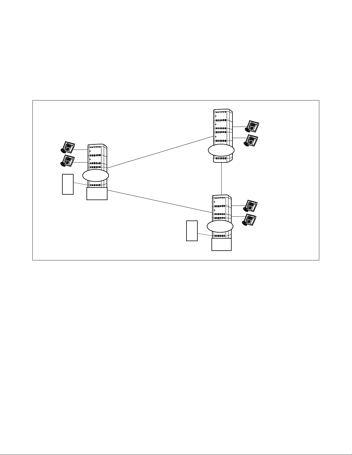
3.7.2 Multiple IPs
3.7.2.1 Functional Outline
In this configuration (Multiple IPs), IP can be accommodated to multiple nodes in a Fusion Network.
Since Series 7400 (Release 8) software, establishing the CCIS line is not necessary to use OAI system
through the network. (“Facility” which can be used through the Fusion Network varies in “the OAI
application”.)
OFFICE DATA DESIGN
Procedure for Setting Office Data for OAI Serv ic es
Node A
Node B
OAI Terminals
FACILITY
IP
UAP
This feature is available with Series 7400 (Release 8) software.
3.7.2.2 Using Conditions
(a) Telephone Number (max. 5 digi ts) i s use d f or the stat ion nu mber type t o act i vated OAI system
through Fusion network.
FCCS
FCCS
UAP
FCCS
FACILITY
FACILITY
IP
Node C
OAI Terminals
OAI Terminals
(b) Logical Route is used for the route type to activate OAI system through Fusion net work.
(c) Only one IP to be used for “OAI Terminal Anywhere” can be contained in a Fusion Network
(Multiple IPs).
(d) IP can be accommodated to multiple nodes in a Fusion Netw ork. Ho wever, maximum number
of Status Monitoring Requests to a terminal is decided by the system data (max. 8 ports
available including UAP). Note that the normal operation is not guaranteed if Status
Monitoring is requested to a terminal from more than the number of ports.
ND-70895 (E) CHAPTER 5
Page 81
Revision 1.0
Page 92

OFFICE DATA DESIGN
...
...
...
...
...
...
...
...
...
...
...
...
...
...
...
...
Procedure for Setting Office Data for OAI Services
(e) OAI terminals to be controlled from different IPs can not be accommodated in a node.
Node A
IP
Node B
IP
FCCS
OAI Terminals
FCCS
FCCS
... ... ...
... ...
... ... ...
... ...
... ... ...
... ...
... ... ...
... ...
... ... ...
... ...
... ... ...
... ...
... ... ...
... ...
... ... ...
... ...
Node C
... ... ...
... ...
... ... ...
... ...
... ... ...
... ...
... ... ...
... ...
... ... ...
... ...
... ... ...
... ...
... ... ...
... ...
... ... ...
... ...
OAI Terminals
(f) When the I MG-U s ystem is in clud ed in a Fus ion Ne twork (M ulti ple IP s), t ake the f ollowing
conditions into consideration when programming data.
(a) IMG-U system where the OAI terminals are accommodated in multiple Local Nodes.
In the IMG-U system, data programming for “OAI terminal Anywhere” must be programmed at
the node that has IP (“IP1” in the figure below). In the network, another IP can not be used for
“OAI terminal Anywhere” any more.
IMG-U
LN
LN
IP1
LN
LN
LN
LN
IP2
LEGEND
: Local Node that
LN
has OAI terminals
3.7.2.3 Data Programming
[Notice for Data Programming]
This section shows data programming divided into the types of OAI system (Figure 5-1).
The following are the network configuration of OAI system in a Fusion Network.
LEGEND
PBX1 PBX2IIP
PBX3 PBX4
IP
III
Fusion Network
CHAPTER 5 ND-70895 (E)
Figure 5-1 Network Configuration of OAI systems
Page 82
Revision 1.0
Type I : PBX1 - Non - OAI system
II
Type II : PBX2 - OAI Stand-alone system (OAI system provides OAI
function in the self-node only)
Type III : OAI Terminal Anywhere
PBX3 - System providing the OAI terminals (Non-IP Node)
PBX4 - System providing the OAI terminals (IP-Node)
Page 93

1. The following a r e the quick refere nce table of op tional software and system data programming for
each OAI system configuration. (See Figure 5-1 “Network Configuration of OAI systems” for
network configuration of OAI systems.)
Table 5-1 OAI Software and System Data
OAI
OAI Software
OAI Option Service software (basic)
1
[Series 7400 (Release 8)]
2 ACD Option Service Software for “Agent Anywhere”
System Data
CM Usage Note 1
3
(ASYD:SYS1, INDEX31, b0~b3)
OAI in service/out of service
4
(ASYD:SYS1, INDEX79, b6)
No.0 CPU Mounted Status of IP00/1: Not mounted/Mounted
5
(ASYD:SYS1, INDEX207, b0)
No.1 CPU Mounted Status of IP00/1: Not mounted/Mounted
6
(ASYD:SYS1, INDEX207, b1)
OAI Call Processing Event Notification
7
(ASYD:SYS1, INDEX241, b2)
SCF Return Error Detail Notification
8
(ASYD:SYS1, INDEX241, b3)
Built-in IP:Not used/Used
9
(ASYDL:SYS1, INDEX864, b0)
OAI Terminal Anywhere:Out of service/In service Note 3
10
(ASYDL:SYS1, INDEX864, b2)
MULTIPLE IPs:Out of service/ In service Note 4
11
(ASYDL:SYS1, INDEX864, b3)
FPC Number of the node providing IP
12
(ASYDL:SYS1, INDEX865)
Number of ports for SMFN (terminal)
13
(ASYDL:SYS1, INDEX864, b4~5)
FPC Number of Center Node providing VNDM (ASYDN:SYS1,
14
INDEX533)
:
The software is installed to be linked with the standard service software using MSVIP command.
Note 1:
Note 2:
Note 3:
Note 4:
Note 5:
Note 6:
Note 7:
When CM is used for another function, this setting may be changed.
(Ex. Assign “6” Hex. when FLF Fusion service is used .)
When the CPU in system 1 is used, assign “1”.
Assign “1” at the all nodes using “OAI Terminal Anywhere” in the Fusion network that “MULTIPLE IPs” is provided.
When the all fusion nodes in the network are used for “MULTIPLE IPs”, this data may be assigned using ASYDN.
This data is required for UAP connection.
(This data is not necessary for the example above.) Assign this data so that the proper number of ports can be used when
more than three ports of Status Monitoring for terminal (SMFN). The identical data should be assigned at all nodes.
ASYDL SYS1 INDE X864 b4~5:
b5
00=2 ports
01=8 ports
When the node using “OAI Terminal Anywhere” is included in the Fusion network that “Multiple IPs” is provided, assign
the FPC no. of IP node using “OAI Terminal Anywhe re”.
b4
Procedure for Setting Office Data for OAI Serv ic es
Type and Node
OFFICE DATA DESIGN
I II III
PBX1 PBX2 PBX3 PBX4
0444
1000
0101
0 Note 2 0 Note 2
0111
0111
0101
0011
0011
00Note 5 Note 5
0 N ote 6 Note 6 Note 6
Note 7 Note 7 Note 7 Note 7
ND-70895 (E) CHAPTER 5
Page 83
Revision 1.0
Page 94
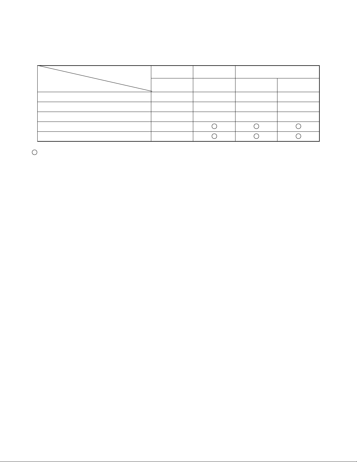
OFFICE DATA DESIGN
Procedure for Setting Office Data for OAI Services
2. Some notices for PBX commands data programming are described below. (See Figure 5-1
“Network Configur ation of OAI sys tems” for network configuration of OAI systems.)
Type and Node
PBX Command Data
Monitor Number Data (AMNO) N/L N
Conversion Number Data (ACNO) N/L N
Announcement/Dictation Data (AADT) N N
OAI Key Code Data (AOKC)
Key Data for D
term
(AKYD)
I II III
PBX1 PBX2 PBX3 PBX4
: Assign data by the corresponding commands wri tten in DM.
N : Assign data by the correspondi ng commands written in NDM.
L : Assign data by the correspond ing commands written in LDM when the call is not terminated from other node s.
CHAPTER 5 ND-70895 (E)
Page 84
Revision 1.0
Page 95
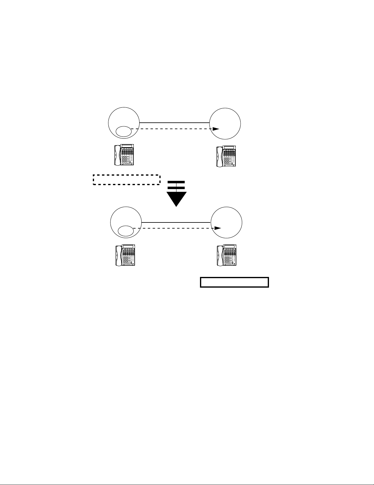
3.7.3 Example of Use of Facility on Fusion Network
...
...
...
...
...
...
...
...
...
...
...
...
...
...
...
...
As a example of use of facilities through Fusion Network, the explanations will give in the following
about Free Location Facility (FLF).
By using Free Location Facility (FLF) through Fusion Network, OAI Logical Number services can be
used at any nodes in the Fusion network. This feature is available with the Series 7400 (Release 8)
software.
OFFICE DATA DESIGN
Procedure for Setting Office Data for OAI Serv ic es
Node A
IP
... ... ... ... ...
... ... ... ... ...
... ... ... ... ...
... ... ... ... ...
Station Number : 200
OAI Logical Number : 5000
Node A
IP
... ... ... ... ...
... ... ... ... ...
... ... ... ... ...
... ... ... ... ...
Station Number : 200
Node B
... ... ... ... ...
... ... ... ... ...
... ... ... ... ...
... ... ... ... ...
Station Number : 300
OAI Logical Number 5000 is
converted from Station Number 200
to Station Number 300
Node B
...
...
...
... ...
...
...
...
... ...
...
...
...
... ...
...
...
...
... ...
Station Number : 300
OAI Logical Number : 5000
Note:
This service enables the Free Location Facility (FLF) beyond the nodes via the Fusion link. For
example, if OAI Logical Number 5000 is converted from Station Number 200 at Node A to Station
Number 300 at Node B. (Station Number 200 = OAI Logical Number 5000 → Station Number 300 =
OAI Logical Number 5000)
Information on OAI Logical Number Development is broadcast to all (Fusion network) nodes.
For this service, assign the system data as follows;
ASYD-SYS1 INDEX 31:06 (Mounting Capacity of Common Memory (CM) 6 Mbytes)
ASYDN-SYS1 INDEX 870, b0=1(FLF Fusion service is available)
ASYDL-SYS1 INDEX 864, b6=1 (FLF Error detailed Information is provided)
ND-70895 (E) CHAPTER 5
Page 85
Revision 1.0
Page 96

This page is for your notes.
CHAPTER 5 ND-70895 (E)
Page 86
Revision 1.0
Page 97

CHAPTER 6 MAINTENANCE
This chapter expl ains maintenance, fa ult diagnosis out of sys tem messages, fault repair procedure of the NEAX2400
IMX OAI System.
1. General
When a fault has been discov ered in the cou rse of mainte nance works, t he fault is to be diagnosed out of system
messages an d is to be repaire d by the following fault re pair procedure (Refer to Figure 6-1).
2. MAINTENANCE
• Routine Maintenance
System messages
indicating OAI fault
4. FAULT DIAGNOSIS
• Diagnosis out of System Messages
Figure 6-1 Flow of Maintenance Works
3. SYSTEM MESSAGES
• Message Detail Data
ND-70895 (E) CHAPTER 6
Page 87
Revision 1.0
Page 98

MAINTENANCE
Maintenance
2. Maintenance
2.1 Routine Maintenance
By the routine maintenance on the NEAX2400 IMX OAI System, the following are performed.
1. System messages pertaining to OAI faults
A check is made to see if any system message pertaining to OAI faults is printed out. (Refer to
Chapter 6, Section 3.1)
2.1.1 System Messages and Lamp Indications on TOPU
In the OAI s ystem, an alar m lamp on TOPU cor respondi ng to the faul ty equipment lights up. The alarm
lamps on TOPU corresponding to system messages are shown in Table 6-1.
Table 6-1 Relationship betwe e n System Messages and Alarm Lamps on TOPU
SYSTEM MESSAGE FRAME-TOP LAMP
No. NAME MJ MN SUP
REMARKS
4-R I/O Card Fault of IP
26-V LAN Interface Error Report
×
×
CHAPTER 6 ND-70895 (E)
Page 88
Revision 1.0
Page 99

3. System Messages
3.1 Outline
If any of the NEAX2400 IMX OAI functions becomes faulty , the corresponding system message shown in
Table 6-2 is displayed. This se ction e xplai ns th e mea ning o f each syst em messag e and me ssa ge det ail d ata.
MAINTENANCE
System Messages
Table 6-2 System Messages of OAI System
SYSTEM
MESSAGE No.
4-R TCP/IP Link Failure A fault has occurred to the UAP or to the line connected with the
26-V LAN Interface Error Report A fault, related to the TCP/IP connection between the PBX and
FAULT CONTENTS OF FAULT
external computer.
Host, occurred.
ND-70895 (E) CHAPTER 6
Page 89
Revision 1.0
Page 100
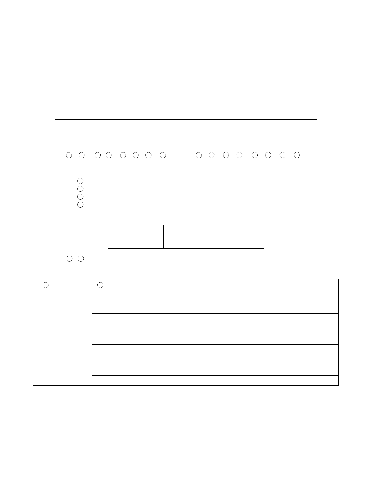
MAINTENANCE
System Messages
3.2 Message Detail Dat a
This paragraph describes the detailed information on the faults indicated by system messages (message
detail data).
3.2.1 Message Detail Data of System Mes sage “4- R”
System Message 4-R: TCP/IP Link Failure
1. Print-out Format
SYSTEM MESSAGE 4-R TCP/IP Link Failure
NEC - ESD DEC 22 21:32
1: xx xx xx xx xx xx xx xx 2: 00 00 00 00 00 00 00 00
1 2 3 4 5 6 7 8 9
2. Print-out infor m ation (typical)
1
Fault port number: 0-5
2
Communication Protocol: 03 = ETHER + TCP/IP
3
Error Code (ERRK): Refer to the table below (6-3 ERROR CODE)
4
Fault logic al channel number (LCID) : 01~10H (00 means the data is invalid)
10 11 12 13 14 15 16
Relation between LCID and PBX TCP port number
LCID TCP port number of the PBX
01 60030
5 8
~ IP address
Table 6-3 Error Code
2 3
PROTOCOL ERROR CODE CONTENT OF FAULT
03
(ETHER + TCP/IP)
01 TCP Connection disconnected (Normal) Note 1
02 Reception of a text that cannot be analyzed Note 2
03~09 Not used
10 (0A) TCP Connection disconnected (On the way) Note 2
11 (0B) Transmission to PZ-PC19 (LANI) i s disabled (Permanent) Note 2
12 (0C) Abnormal UAP is detected by Heart Beat function
13 (0D) Not used
14 (0E) TCP/IP Connection Error (B-level Infinite Loop, etc.) Note 2
15 (0F) Not used
Note 1:
This error code shows that the Host (UAP) is down manually. You can program not to output this detail
message at some offices using SYS1, INDEX864, b1 in ASYDL (Other messages than ERRK = 01 is output
when TCP connection disconnect ed is not output).
Note 2:
This data is output fo r Series 730 0 Release 6 or e arlie r. If your system is Series 7300 Release 7 or later, the
message is out p ut by 26-V” ins t e ad. (Refer to Section 3.2.2)
CHAPTER 6 ND-70895 (E)
Page 90
Revision 1.0
 Loading...