

Page 1

NWA-008869-001
ISSUE 1
In-Skin Router Installation Guide
JUNE, 2005
NEC Corporation
Page 2

LIABILITY DISCLAIMER
NEC Corporation reserves the right to change the specifications,
functions, or features, at any time, without notice.
NEC Corporation has prepared this document for use by its
employees and customers. The information contained herein is the
property of NEC Corporation and shall not be reproduced without
prior written approval from NEC Corporation.
NEAX and D
term
are registered trademark of NEC Corporation.
Copyright 2005
NEC Corporation
Printed in Japan
Page 3

PAG E No.
i 1
ii 1
iii 1
iv
1 1
2 1
3 1
4
5 1
6 1
7 1
8
9 1
10 1
11 1
12
13 1
14 1
15 1
16
17 1
18 1
19 1
20
21 1
22 1
23 1
24
25 1
26 1
27 1
28
29 1
30 1
31 1
32
33 1
34 1
DATE JUNE, 2005 DATE DATE DATE
DATE DATE DATE DATE
12345678
1
1
1
1
1
1
1
1
1
ISSUE 1 ISSUE 2 ISSUE 3 ISSUE 4
ISSUE 5 ISSUE 6 ISSUE 7 ISSUE 8
ISSUE No.
PAG E N o.
35 1
36
37 1
38 1
39 1
40
41 1
42 1
43 1
44
45 1
46 1
47 1
48
49 1
50 1
51 1
52
53 1
54 1
55 1
56
57 1
58 1
59 1
60
61 1
62 1
63 1
64
65 1
66 1
67 1
68
69 1
70 1
71 1
72
12345678
1
1
1
1
1
1
1
1
1
1
ISSUE No.
NEAX IPS
In-Skin Router Installation Guide
Revision Sheet 1/3
NWA-008869-001
Page 4

PAG E No.
73 1
74 1
75 1
76
77 1
78 1
79 1
80
81 1
82 1
83 1
84
85 1
86 1
87 1
88
89 1
90 1
91 1
92
93 1
94 1
95 1
96
97 1
98 1
99 1
100
101 1
102 1
103 1
104
105 1
106 1
107 1
108
109 1
110 1
DATE JUNE, 2005 DATE DATE DATE
DATE DATE DATE DATE
12345678
1
1
1
1
1
1
1
1
1
ISSUE 1 ISSUE 2 ISSUE 3 ISSUE 4
ISSUE 5 ISSUE 6 ISSUE 7 ISSUE 8
ISSUE No.
PAG E No.
111 1
112
113 1
114 1
115 1
116
117 1
118 1
119 1
120
121 1
122 1
123 1
124
125 1
126 1
127 1
128
129 1
130 1
131 1
132
133 1
134 1
135 1
136
137 1
138 1
139 1
140
141 1
142 1
143 1
144
145 1
146 1
147 1
148
12345678
1
1
1
1
1
1
1
1
1
1
ISSUE No.
NEAX IPS
In-Skin Router Installation Guide
Revision Sheet 2/3
NWA-008869-001
Page 5

PAG E No.
149 1
150 1
151 1
152
153 1
154 1
155 1
156
157 1
158 1
159 1
160
161 1
162 1
163 1
164
165 1
166 1
A1 1
A2
A3 1
A4 1
ISSUE No.
12345678
1
1
1
1
1
PAG E No.
ISSUE No.
12345678
ISSUE 1 ISSUE 2 ISSUE 3 ISSUE 4
DATE JUNE, 2005 DATE DATE DATE
ISSUE 5 ISSUE 6 ISSUE 7 ISSUE 8
DATE DATE DATE DATE
NEAX IPS
In-Skin Router Installation Guide
Revision Sheet 3/3
NWA-008869-001
Page 6

THIS PAGE LEFT BLANK INTENTIONALLY.
Page 7

NEAX IPS
In-Skin Router Installation Guide
TABLE OF CONTENTS
INTRODUCTION .................................................................................................................. 1
PURPOSE .................................................................................................................... 1
OUTLINE OF THIS MANUAL ...................................................................................... 1
TERMS IN THIS MANUAL ........................................................................................... 3
PBX System Designation ................................................................................................... 3
Terminal Name .................................................................................................................... 3
REFERENCE MANUAL ............................................................................................... 4
CHAPTER 1 GENERAL INFORMATION .......................................................................... 5
SYSTEM OUTLINE ...................................................................................................... 6
Main Feature of In-Skin Router .......................................................................................... 6
IPv6/IPv4 Tunneling ............................................................................................................ 7
Broadband Service Support .............................................................................................. 8
Network Connection ........................................................................................................... 9
CARD NAME AND FUNCTION ................................................................................... 10
SYSTEM CONDITIONS ............................................................................................... 11
Ethernet Connection .......................................................................................................... 11
Digital Private Line Connection ......................................................................................... 11
Local Console Connection ................................................................................................ 11
CHAPTER 2 INSTALLATION ............................................................................................. 13
PRECAUTIONS ........................................................................................................... 14
Static Electricity Guard ...................................................................................................... 14
REQUIRED EQUIPMENT ............................................................................................ 17
INSTALLATION PROCEDURE ................................................................................... 19
Switch Settings of MP Card ............................................................................................... 21
Switch Settings of PN-RTA Card ....................................................................................... 33
Switch Settings of PZ-M649 Card ...................................................................................... 36
Switch Settings of PZ-M650 Card ...................................................................................... 39
Switch Settings of PN-24DTA-C Card ............................................................................... 42
Switch Settings of PN-30DTC-C Card ............................................................................... 48
Locations of Lamps and Connectors of PZ-M623 Card .................................................. 53
Mounting PZ-M649 Card/PZ-M650 Card/PZ-M623 Card ................................................... 54
Mounting PN-RTA Card ...................................................................................................... 55
LAN Cable Connection of PN-RTA Card ........................................................................... 57
Cable Connection of PZ-M649 Card .................................................................................. 58
Cable Connection of PZ-M650 Card .................................................................................. 63
– i –
NWA-008869-001 Rev.1.0
attoc001.fm
Page 8

TABLE OF CONTENTS
LAN Cable Connection of PZ-M623 Card ......................................................................... 68
Connecting Local Console to PN-RTA Card .................................................................... 69
CHAPTER 3 BASICOPERATIONS AND VARIOUS EXPLANATIONS ............................ 71
COMMAND ENTRY ..................................................................................................... 72
Commands .......................................................................................................................... 72
Error message that may be displayed during command entry ...................................... 72
KEY OPERATIONS AND SCREEN DISPLAYS .......................................................... 73
Moving the cursor ...............................................................................................................73
Editing characters on the command line ......................................................................... 73
Calling previously entered commands ............................................................................. 74
Getting assistance in command entry .............................................................................. 75
Entering an abbreviation of a command .......................................................................... 76
Help functions ..................................................................................................................... 76
Screen displays .................................................................................................................. 77
Notes on command entry ................................................................................................... 77
MODES ........................................................................................................................ 78
Mode configuration ............................................................................................................ 78
Changing the In-Skin Router between operation and config modes ............................. 79
Changing the In-Skin Router between different config modes ...................................... 80
From operation mode to login authentication (logout) ................................................... 80
LOGIN AND USER RIGHTS ........................................................................................ 81
User rights ........................................................................................................................... 81
Registering users and setting user rights ........................................................................ 81
Changing passwords ......................................................................................................... 82
Erasing users ...................................................................................................................... 83
Login .................................................................................................................................... 83
Use of modes by more than one user ............................................................................... 84
SETTING DATA AND PROGRAM FILES ................................................................... 85
Setting data and programs ................................................................................................ 85
Locations used to store setting data and the program ................................................... 86
Startup config and running config .................................................................................... 87
Startup sequence ................................................................................................................87
CHAPTER 4 INITIALIZATION ........................................................................................... 91
INITIALIZATION PROCEDURE ................................................................................... 92
TURNING ON THE POWER ........................................................................................ 93
REGISTERING USERS AND SETTING PASSWORDS .............................................. 94
SETTING THE DATE AND TIME ................................................................................. 96
SETTING DEVICE NAMES .......................................................................................... 97
SAVING RUNNING CONFIG ....................................................................................... 98
– ii –
NWA-008869-001 Rev.1.0
attoc001.fm
Page 9

TABLE OF CONTENTS
RESTARTING THE IN-SKIN ROUTER WITH A COMMAND AND LOGGING IN ...... 99
TURNING OFF THE POWER TO TERMINATE THE IN-SKIN ROUTER .................... 100
SETTING UP THE LAN PORTS FOR SUITABLE COMMUNICATION MODES ........ 101
Setup method ...................................................................................................................... 101
SETTING UP THE WAN PRIVATE LINE (T1) ............................................................. 104
Setting line attributes for a T1 Line ................................................................................... 104
Shutting down and restarting the interface for the settings to take effect ................... 105
Saving setting data .............................................................................................................105
Checking the status of interface ....................................................................................... 105
SETTING UP THE WAN PRIVATE LINE (E1) ............................................................. 106
Setting line attributes for an E1 Line ................................................................................ 106
Shutting down and restarting the interface for the settings to take effect ................... 107
Saving setting data .............................................................................................................107
Checking the status of interface ....................................................................................... 107
SETUP FOR A REMOTE CONSOLE .......................................................................... 108
Setting an IP address and validating the interface .......................................................... 109
Checking the settings ........................................................................................................ 110
Starting up the telnet server .............................................................................................. 111
Checking the communication state .................................................................................. 112
Saving setting data .............................................................................................................114
CHAPTER 5 EXAMPLES OF SETUP ON NETWORKS ................................................... 115
ROUTING SETUP EXAMPLES (IPv4) ........................................................................ 116
Setting a static route ..........................................................................................................117
Setting RIP and RIPv2 ........................................................................................................ 118
Checking the communication state .................................................................................. 119
ROUTING SETUP EXAMPLES (IPv6) ........................................................................ 120
Enabling automatic address setting ................................................................................. 121
Setting a static route ..........................................................................................................121
Setting RIPng ...................................................................................................................... 122
Checking the communication state .................................................................................. 123
PPPoE SETUP EXAMPLE .......................................................................................... 124
Setup procedure .................................................................................................................125
Shutting down a PPPoE connection ................................................................................. 126
DIGITAL PRIVATE LINE NETWORK EXAMPLE (T1) ................................................ 127
Setup procedure .................................................................................................................128
DIGITAL PRIVATE LINE NETWORK EXAMPLE (E1) ................................................ 130
Setup procedure .................................................................................................................131
CHAPTER 6 MANAGEMENT AND MAINTENANCE ....................................................... 135
TFTP SETUP FOR FILE MANAGEMENT ................................................................... 136
– iii –
NWA-008869-001 Rev.1.0
attoc001.fm
Page 10

TABLE OF CONTENTS
CONFIG MANAGEMENT ............................................................................................ 137
Saving with the write memory command ......................................................................... 137
Config management with text files ................................................................................... 138
UPGRADING THE PROGRAM .................................................................................... 139
Upgrading procedure ......................................................................................................... 140
MANAGEMENT WITH SNMP ...................................................................................... 144
Setup procedure .................................................................................................................145
SETTING UP EVENT INFORMATION COLLECTION ................................................ 148
Displaying event information on a console ..................................................................... 149
Transferring event information to a syslog server .......................................................... 150
TELNET SECURITY .................................................................................................... 151
RESTARTING THE IN-SKIN ROUTER DURING OPERATION .................................. 152
Restarting by turning the power switch OFF and back ON ............................................ 152
Restarting with the reload command ................................................................................ 152
Restarting with the restart command ............................................................................... 153
SUPER RESET ............................................................................................................ 154
Procedure for performing a super reset ........................................................................... 154
CHAPTER 7 TROUBLESHOOTING ................................................................................. 157
IF THE LOCAL CONSOLE CANNOT BE USED ......................................................... 158
IF A REMOTE CONSOLE CANNOT BE USED .......................................................... 159
IF COMMUNICATION IS IMPOSSIBLE ...................................................................... 160
If communication with a specific network is impossible ................................................ 160
If communication is sometimes possible and sometimes impossible .......................... 160
If no communication is possible ....................................................................................... 160
IF THE IN-SKIN ROUTER DOES NOT START ........................................................... 161
If the ALARM lamp on the PN-RTA card is lit ................................................................... 161
If none of the lamps on the PN-RTA card is lit ................................................................. 161
If the boot monitor mode screen is displayed ................................................................. 161
COLLECTING FAULT INFORMATION ....................................................................... 164
IF YOU WANT TO ERASE CONFIG ........................................................................... 165
If you want to restore the settings of running config to those of startup config ......... 165
If you want to erase all settings of config ........................................................................ 165
IF SELF-DIAGNOSIS DOES NOT TERMINATES NORMALLY ................................. 166
APPENDIX SPECIFICATIONS .......................................................................................... A1
SPECIFICATIONS ....................................................................................................... A2
– iv –
NWA-008869-001 Rev.1.0
attoc001.fm
Page 11

INTRODUCTION
PURPOSE/OUTLINE OF THIS MANUAL
INTRODUCTION
PURPOSE
This manual explains the system description, the hardware installation, each settings and operation, information for management and maintenance, and specifications for the In-Skin Router of the NEAX 2000
IPS INTERNET PROTOCOL SERVER.
OUTLINE OF THIS MANUAL
This manual consists of seven chapters and one appendix. The following paragraphs summarize Chapters
1 through 7 and appendix.
CHAPTER 1 GENERAL INFORMATION
This chapter explains the system outline, card name and function, and system
conditions for In-Skin Router.
CHAPTER 2 INSTALLATION
This chapter explains the required equipment and the hardware installation
procedure to provide In-Skin Router.
CHAPTER 3 BASIC OPERATIONS AND VARIOUS EXPLANATIONS
This chapter explains the each key function that is used by the console, each of
mode, login and user rights, and the program configuration.
CHAPTER 4 INITIALIZATION
This chapter explains the basic setup operations that you must perform initially.
Also explains the required setup for connecting a remote console.
CHAPTER 5 EXAMPLES OF SETUP ON NETWORKS
This chapter explains examples of setup for routing on IPv4 and IPv6 networks.
CHAPTER 6 MANAGEMENT AND MAINTENANCE
This chapter explains the information for maintenance and management, including
file management, program upgrading, and event information collection procedures.
CHAPTER 7 TROUBLESHOOTING
This chapter explains the information that you may find helpful if an unexpected
error occurs.
– 1 –
NWA-008869-001 Rev.1.0
atch0001.fm
Page 12

APPENDIX SPECIFICATIONS
This appendix explains specifications related to the In-Skin Router.
INTRODUCTION
OUTLINE OF THIS MANUAL
– 2 –
NWA-008869-001 Rev.1.0
atch0001.fm
Page 13

INTRODUCTION
TERMS IN THIS MANUAL
TERMS IN THIS MANUAL
PBX System Designation
PBX system is designated as “PBX” or “system” usually.
When we must draw a clear line between the PBX system, they are designated as follows.
2000 IPS : NEAX 2000 IPS INTERNET PROTOCOL SERVER
DMR
IPS
IPS
: NEAX IPS
DM
: NEAX IPSDM INTERNET PROTOCOL SERVER
Term inal Nam e
The following IP terminals are designated as “D
minal in particular.
term
D
IP (IP Adapter Type) [For North America Only]
term
D
IP (IP Bundled Type)
term
D
IP INASET
term
D
SP20
term
D
SP30
DMR
INTERNET PROTOCOL SERVER
term
IP” usually, unless we need to mention the type of ter-
DMR
DM
NOTE 1: D
IP Adapter (IP Enabled D
able in D
term
75 (Series E)/D
term
IP.
term
85 (Series i) terminal can be used as the IP terminal by attaching the
term
). This terminal provides users with all features currently avail-
NOTE 2: In regard to China market, we have not released NEAX 2000 IPS INTERNET PROTOCOL
SERVER but NEAX 2000 is released.
– 3 –
NWA-008869-001 Rev.1.0
atch0001.fm
Page 14

INTRODUCTION
REFERENCE MANUAL
REFERENCE MANUAL
During installation, refer also to the manuals below:
System Manual:
Contains the system description, hardware installation procedure and programming procedure for the
NEAX 2000 IPS System.
Installation Procedure Manual:
Contains the installation procedure for the PBX system.
– 4 –
NWA-008869-001 Rev.1.0
atch0001.fm
Page 15

CHAPTER 1 GENERAL INFORMATION
CHAPTER 1
GENERAL INFORMATION
This chapter explains the system outline, card name and function, and system
conditions for the In-Skin Router.
SYSTEM OUTLINE .................................................................... 6
CARD NAME AND FUNCTION ................................................. 10
SYSTEM CONDITIONS ............................................................. 11
– 5 –
NWA-008869-001 Rev.1.0
atch1001.fm
Page 16

CHAPTER 1 GENERAL INFORMATION
SYSTEM OUTLINE
SYSTEM OUTLINE
The In-Skin Router is an IPv6 high-speed access router that can be accommodated in NEAX 2000 IPS.
With its full security functions, it allows you to create reliable, high-speed and high-quality networks.
Main Feature of In-Skin Router
High-speed transfer capability
With a high-speed software platform equipped, the In-Skin Router offers the transfer capability that can
accommodate the traffic of the information that are on the increase in the network.
IPv6 support
The In-Skin Router supports standard IPv6 functions, accommodating IPv4 and IPv6 dual stacks. It also
supports tunneling functions such as IPv6 over IPv4 and IPv4 over IPv6, making it easy for you to shift to
an IPv6 network while taking advantage of your existing IPv4 network.
Broadband support
With the PPPoE protocol equipped, the router allows you to use broadband services such as ADSL and
FTTH.
Full security functions
The In-Skin Router provides IPsec functions, allowing you to create a VPN over the Internet (PZ-M649
card/PZ-M650 card/PZ-M623 card is required).
Dynamic filtering functions, the router protects the internal network from illegal access and attack from
the outside.
Backup Power
The battery of NEAX 2000 IPS is available as the backup power of In-Skin Router, in case of power failure
etc. The backup power for In-Skin Router is not required.
– 6 –
NWA-008869-001 Rev.1.0
atch1001.fm
Page 17

CHAPTER 1 GENERAL INFORMATION
SYSTEM OUTLINE
IPv6/IPv4 Tunneling
Tunneling is the function that the information of a protocol is encapsulated into the packet of an another
protocol and transferred. Tunneling makes it possible to transfer data between networks having different
protocols. A maximum of eight tunnels are available, of which one is an automatic tunnel, and reserved.
Many of the present networks are created with IPv4 and, therefore, IPv6 networks will be separated by
IPv4 networks. If you want to shift to an IPv6 network in a stepwise manner, you can set a tunnel for the
communication between hosts.
An In-Skin Router encapsulates an IPv6 packet into a IPv4 datagram to send the encapsulated packet over
the IPv4 network. Upon receiving the encapsulated packet, another In-Skin Router extracts the IPv6 packet
from the IPv4 packet and sends it to an IPv6 host.
By using an existing IPv4 network, you can shift smoothly to an IPv6 network.
IPv6 over IPv4
IPv6 network
IPv6 Host
2000 IPS 2000 IPS
In-Skin Router
IPv6 packet IPv6 packetIPv4 packet
Encapsulation
IPv4 network
Tunneling
IPv6 network
In-Skin Router
IPv6 Host
Packet extraction
– 7 –
NWA-008869-001 Rev.1.0
atch1001.fm
Page 18

CHAPTER 1 GENERAL INFORMATION
SYSTEM OUTLINE
Broadband Service Support
With the PPPoE protocol equipped, this device allows you to connect to carriers that employ the PPPoE
protocol for connection to broadband services such as ADSL and FTTH.
* Different carriers provide different services. You must check the details of services beforehand.
Broadband Service Support
Office A
2000 IPS
In-Skin Router
MP
HUB HUB
PPPoE
ADSL
modem
To Internet
Internet service
provider
Office B
2000 IPS
In-Skin Router
MP
HUB HUB
PPPoE
ONU
ADSL line
Carrier
network
Optical fiber
ONU: Optical Network Unit
– 8 –
NWA-008869-001 Rev.1.0
atch1001.fm
Page 19

CHAPTER 1 GENERAL INFORMATION
SYSTEM OUTLINE
Network Connection
The In-Skin Router enables the connection with IP network and Digital Private Line (PZ-M649/PZ-M650
card is required).
Network Connection
2000 IPS
PZ-M649/
LEGACY TERMINAL
(SLT/D
term
)
LC/
DLC Card
PZ-M650
Card
T1/E1
Digital Private Line
DTI Card
NOTE
In-Skin Router
MP
HUB
PC D
HUB
term
IP
LAN
Local Console
NOTE: When originating a call from legacy terminal (single line telephone/D
network (T1) via PZ-M649 card, PN-24DTA-C (DTI) card is required.
When originating a call from legacy terminal (single line telephone/D
network (E1) via PZ-M650 card, PN-30DTC-C (DTI) card is required.
IP network
term
) to a digital private
term
) to a digital private
– 9 –
NWA-008869-001 Rev.1.0
atch1001.fm
Page 20

CHAPTER 1 GENERAL INFORMATION
CARD NAME AND FUNCTION
The table below shows the circuit card name and function for In-Skin Router.
In-Skin Router Card Name and Function
CARD NAME AND FUNCTION
CARD NAME
FUNCTION
NAME
PN-RTA RTA In-Skin Router Card
10/100BASE-TX: 1, 10BASE-T: 1, RS-232C (D-sub 9pin)
Maximum 8 cards per PIM
PZ-M649 DTI T1 Digital Trunk Interface (1.5 Mbps) Card
Mounted on PN-RTA Card
Provided a built-in CSU.
PZ-M650 DTI E1 Digital Trunk Interface (2 Mbps) Card
Mounted on PN-RTA Card
Provided a built-in CSU.
PZ-M623 ETHER Ether Control Card
Mounted on PN-RTA Card
10BASE-T: 1
FUNCTIONAL
– 10 –
NWA-008869-001 Rev.1.0
atch1001.fm
Page 21

CHAPTER 1 GENERAL INFORMATION
SYSTEM CONDITIONS
SYSTEM CONDITIONS
Ethernet Connection
For the LAN Ports of In-Skin Router, straight or cross cable (UTP or STP) is required. Prepare the cable
according to the equipment to be connected with the In-Skin Router, such as HUB, ADSL modem or PC.
Digital Private Line Connection
PZ-M649 card is required for connection with the digital private line (T1).
PZ-M650 card is required for connection with the digital private line (E1).
Local Console Connection
In-Skin Router is equipped with a console port. By connecting the local console (such as PC) to the console
port, you can perform basic setup of In-Skin Router from the local console.
As the connecting cable, the MAT cable (MAT CA-P/MAT CA-R/MAT CA-T) is required.
The local console requires a communication software conforming to VT-100. The communication software should be set as follows.
Item Setting
Communication rate 9600 bps
Data length 8 bits
Parity None
No. of stop bits 1 bit
Flow control None
– 11 –
NWA-008869-001 Rev.1.0
atch1001.fm
Page 22

THIS PAGE LEFT BLANK INTENTIONALLY.
– 12 –
NWA-008869-001 Rev.1.0
atch1001.fm
Page 23

CHAPTER 2 INSTALLATION
CHAPTER 2
INSTALLATION
This chapter explains the required equipment and the hardware installation
procedure to provide the In-Skin Router.
PRECAUTIONS ......................................................................... 14
REQUIRED EQUIPMENT .......................................................... 17
INSTALLATION PROCEDURE ................................................. 19
– 13 –
NWA-008869-001 Rev.1.0
atch2001.fm
Page 24

CHAPTER 2 INSTALLATION
PRECAUTIONS
Static Electricity Guard
You must wear a grounded wrist strap to protect circuit cards from static electricity.
Static Electricity Guard
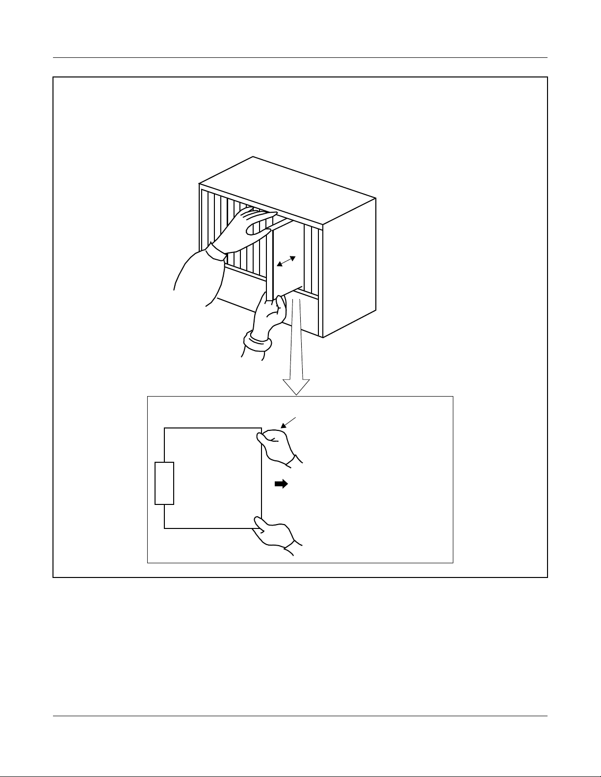
• WHEN PLUGGING/UNPLUGGING A CIRCUIT CARD
PBX
PRECAUTIONS
WRIST STRAP
• WHEN HOLDING A CIRCUIT CARD
FRAME GROUND SCREW
NEVER TOUCH THE COMPONENTS OR
SOLDERED SURFACE WITH BARE HANDS.
CARD FRONT
Continued on next page
– 14 –
NWA-008869-001 Rev.1.0
atch2001.fm
Page 25

Static Electricity Guard
• WHEN MAKING A SWITCH SETTING ON A CIRCUIT CARD
CIRCUIT
CARD
WEAR A WRIST STRAP AND PERFORM
THE WORK ON A GROUNDED
CONDUCTIVE WORK SURFACE.
• WHEN CARRYING A CIRCUIT CARD
CHAPTER 2 INSTALLATION
PRECAUTIONS
CIRCUIT
CARD
POLYETHYLENE
BAG
WHEN CARRYING A CIRCUIT
CARD AROUND, KEEP THE
CARD IN A CONDUCTIVE
POLYETHYLENE BAG.
The mark shown below is attached to the sheet for the work in which circuit cards are handled. When engaging in such work, the installer must be careful not to cause damage by static electricity.
ATTENTION
Contents
Static Sensitive
Handling
Precautions Required
CONDUCTIVE
– 15 –
NWA-008869-001 Rev.1.0
atch2001.fm
Page 26
CHAPTER 2 INSTALLATION
PRECAUTIONS
CAUTION
You must hold the edge of a circuit card when plugging or unplugging the circuit card. If you
touch another area, you may be exposed to hazard voltages.
PBX
NEVER TOUCH THE COMPONENTS OR SOLDERED SURFACE WITH BARE HANDS.
CARD FRONT
– 16 –
NWA-008869-001 Rev.1.0
atch2001.fm
Page 27

CHAPTER 2 INSTALLATION
REQUIRED EQUIPMENT
REQUIRED EQUIPMENT
This table shows the equipment required when providing the In-Skin Router.
Required Equipment for In-Skin Router
EQUIPMENT DESCRIPTION QUANTITY REMARKS
PN-RTA (RTA) In-Skin Router Card 1-8 Maximum 8/PIM
PZ-M649 (DTI) T1 Digital Trunk Interface (1.5
1-8 Mounted on PN-RTA Card
Mbps) Card
PZ-M650 (DTI) E1 Digital Trunk Interface (2
1-8 Mounted on PN-RTA Card
Mbps) Card
PZ-M623 (ETHER) Ether Control (10BASE-T)
1-8 Mounted on PN-RTA Card
Card
PC* Local Console 1
MAT CA-P
or
MAT CA-R
or
MAT CA-T
MAT cable with 25 pin D-SUB
connector (4 m [158 inch])
MAT cable with 25 pin D-SUB
connector (2 m [79 inch])
MAT cable with 9 pin D-SUB
1 Cable between the In-Skin
connector (2 m [79 inch])
HUB* As required
• 10BASE-T cable
(TIA/EIA category3 or
10BASE-T/100BASE-TX
cable
As required Cable between PN-RTA/PZ-
larger)*
• 100BASE-TX cable
(TIA/EIA category5)*
NOTE
NOTE
Router and local console.
M623 and IP network
Cable length:
Maximum 100 m (328 ft.)
T1 Network cable* Twisted pair cable with RJ-48C
connector
E1 Network cable* Twisted pair cable with RJ-48C
connector
*: Prepared by customers
– 17 –
As required Cable between PZ-M649 and
Digital Private Line (T1)
Cable length:
Maximum 200 m (655 ft.)
for DSX-1
Maximum 1758 m (5764 ft.)
for DS-1
As required Cable between PZ-M650 and
Digital Private Line (E1)
Cable length:
Maximum 400 m (1310 ft.)
NWA-008869-001 Rev.1.0
atch2001.fm
Page 28

CHAPTER 2 INSTALLATION
REQUIRED EQUIPMENT
NOTE: When originating a call from legacy terminal (single line telephone/D
network (T1) via PZ-M649 card, PN-24DTA-C (DTI) card is required.
When originating a call from legacy terminal (single line telephone/D
network (E1) via PZ-M650 card, PN-30DTC-C (DTI) card is required.
term
) to a digital private
term
) to a digital private
– 18 –
NWA-008869-001 Rev.1.0
atch2001.fm
Page 29

CHAPTER 2 INSTALLATION
INSTALLATION PROCEDURE
INSTALLATION PROCEDURE
Install the In-Skin Router according to the procedure below.
For the other NEAX 2000 IPS equipment, refer to the Installation Procedure Manual.
Installation Procedure
START
PZ-M649 is used PZ-M650 is used
Switch Settings of PZ-M649 Card
Page 36
Switch Settings of PN-24DTA-C Card
NOTE 2
Switch Settings of MP Card
Switch Settings of PN-RTA Card
Is PZ-M623 used?
No
Is PZ-M649/
PZ-M650 used?
PZ-M649/
PZ-M650
is not used
Page 21
Page 33
Yes
NOTE 1
Mounting PZ-M623 Card
Switch Settings of PZ-M650 Card
Page 39
Switch Settings of PN-30DTC-C Card
NOTE 3
Page 54
Page 42
Mounting PZ-M649 Card
Page 54
Page 48
Mounting PZ-M650 Card
Page 54
A
Continued on next page
– 19 –
NWA-008869-001 Rev.1.0
atch2001.fm
Page 30

Installation Procedure
A
CHAPTER 2 INSTALLATION
INSTALLATION PROCEDURE
PZ-M649 is used PZ-M650 is used
Cable Connection of PZ-M649 Card
Page 58
Mounting PN-RTA Card
LAN Cable Connection of
PN-RTA Card
Is PZ-M623 used?
No
Is PZ-M649/
PZ-M650 used?
PZ-M649/
PZ-M650
is not used
Page 55
Page 57
Yes
LAN Cable Connection of
PZ-M623 Card
Page 68
Cable Connection of PZ-M650 Card
Page 63
Connecting Local Console to
PN-RTA Card
END
Page 69
NOTE 1: PZ-M623 card has no switches.
Check the lamp indications and location of connectors with reference to Locations of Lamps
and Connectors of PZ-M623 Card. Page 53
NOTE 2: This procedure is required when originating a call from legacy terminal (single line telephone/
term
D
) to a digital private network (T1) via PZ-M649 card.
NOTE 3: This procedure is required when originating a call from legacy terminal (single line telephone/
term
D
) to a digital private network (E1) via PZ-M650 card.
– 20 –
NWA-008869-001 Rev.1.0
atch2001.fm
Page 31

CHAPTER 2 INSTALLATION
INSTALLATION PROCEDURE
Switch Settings of MP Card
PN-CP24-A/PN-CP24-B
ATTENTION
NOTE 1: When you input the external clock signals using PZ-M649 card, set the
switches as follows.
SW4-3: OFF SW4-4: OFF
However, when PN-24DTA card/PN-24CCT card/PN-24PRT card
mounted in PIM0, you do not need to set the switches of MP card.
NOTE 2: When you input the external clock signals using PZ-M650 card, set the switches as follows.
SW4-3: OFF SW4-4: ON
However, when PN-30DTC card/PN-2BRT card/PN-4BRT card/PN-30CCT card mounted in
PIM0, you do not need to set the switches of MP card.
Locations of Lamps, Switches, and Connectors
Contents
Static Sensitive
Handling
Precautions Required
JP1
VR
JP0
SW4
CONN
CONN: To CONN connector on PZ-M606-A (ETHER)
SW3
RUN
SW1
SW2
JACK
SYSD
L0
CLK IN
DK
RS1
RS0
– 21 –
NWA-008869-001 Rev.1.0
atch2001.fm
Page 32

Lamp Indications
CHAPTER 2 INSTALLATION
INSTALLATION PROCEDURE
LAMP
COLOR FUNCTION
NAME
RUN Green Flash (120 IPM): On Line
Flash (slowly) : Off Line
OFF or ON : This card is not operating.
Lights momentarily when initializing this card.
SYSD Red Flashes while writing the system data for backup to the Flash Memory.
Lights while copying the system data from the Flash Memory to the
SDRAM.
L0 Green Flashes while copying the MP program from the Flash Memory to the
SDRAM.
CLK IN Green Remains lit while receiving clock signals to the PLO.
– 22 –
NWA-008869-001 Rev.1.0
atch2001.fm
Page 33

CHAPTER 2 INSTALLATION
INSTALLATION PROCEDURE
Switch Settings
CAUTION
When the operating power is being supplied to this circuit card, do not plug/unplug this circuit
card into/from its mounting slot.
SWITCH NAME
SW3 (Rotary SW)
0
NOTE 1
SWITCH
NUMBER
0-F
SETTING
POSITION
0
2
3
5
NOTE 2
6
NOTE 2
7
NOTE 2
8
NOTE 2
FUNCTION CHECK
On Line
(Call processing is in progress)
Off Line (Call processing is stopped)
• I/O port: As per CM40 Y=08
Off Line (Call processing is stopped)
• I/O port: 9600 bps (Fixed)
Off Line (Call processing is stopped)
• I/O port: 9600 bps
Off Line (Call processing is stopped)
• I/O port: 19200 bps
Off Line (Call processing is stopped)
• I/O port: 38400 bps
Off Line (Call processing is stopped)
• I/O port: 57600 bps
B For clearing the office data
C For setting the resident system program
1, 4, 9
Not used
A, D-F
NOTE 1: Set the groove on the switch to the desired position.
NOTE 2: Only when executing “MP Program Download” using MATWorX, set the SW3 to 5-8.
Continued on next page
– 23 –
NWA-008869-001 Rev.1.0
atch2001.fm
Page 34

CHAPTER 2 INSTALLATION
INSTALLATION PROCEDURE
SWITCH NAME
SWITCH
NUMBER
SETTING
FUNCTION CHECK
POSITION
SW1 (Push SW) For initializing CPU
SW2
(Piano SW)
OFF
4
3
2
1
1
ON
2, 3
ON A-law (Australia)
OFF µ-law (North America)
Selection of PLO0 input
(Phase Locked Oscillator)
• For clock receiver office:
SW2-2 SW2-3 FUNCTION
OFF OFF
ON OFF
1.5 MHz clock
[For PN-24DTA/PN-24CCT/
PN-24PRT/PZ-M649]
192 kHz clock
[For PN-BRTA]
OFF ON
ON ON
2 MHz clock
[For PN-30DTC/PN-2BRT/
PN-4BRT/PN-30CCT/PN-30PRT/
PZ-M650]
Not used
• For clock source office:
SW2-2 SW2-3
OFF OFF
ON
4
When using RS1 port for built-in
MODEM
OFF When using RS1 port for RS-232C
Continued on next page
– 24 –
NWA-008869-001 Rev.1.0
atch2001.fm
Page 35

CHAPTER 2 INSTALLATION
INSTALLATION PROCEDURE
SWITCH
SETTING
SWITCH NAME
NUMBER
SW4 (Dip SW) 1 Not used
ON
123
4
2 Not used
3, 4
POSITION
OFF
OFF
Selection of PLO1 input
(Phase Locked Oscillator)
• For clock receiver office:
SW4-3 SW4-4 FUNCTION
OFF OFF 1.5 MHz clock
[For PN-24DTA/PN-24CCT/
PN-24PRT/PZ-M649]
ON OFF 192 kHz clock
[For PN-BRTA]
OFF ON 2 MHz clock
[For PN-30DTC/PN-2BRT/
PN-4BRT/PN-30CCT/PN-30PRT/
PZ-M650]
FUNCTION CHECK
ON ON Not used
• For clock source office:
SW4-3 SW4-4
OFF OFF
VR (Rotary SW) Variable Resistor for External Hold
20
Tone Source
(0-20 kΩ: Clockwise)
0
DK (Connector)
02
01
02 Ground detection
01 Ground sending
Continued on next page
– 25 –
NWA-008869-001 Rev.1.0
atch2001.fm
Page 36

CHAPTER 2 INSTALLATION
INSTALLATION PROCEDURE
SWITCH NAME
SWITCH
NUMBER
JP0 (Jumper pin)
Front
SETTING
POSITION
UP
DOWN
FUNCTION CHECK
For normal operation
(Battery backup ON)
Not used
(Battery backup OFF)
JP1 (Jumper pin)
RIGHT For using external hold tone source
Front
LEFT
For using internal hold tone source
The figure in the SWITCH NAME column and the position of in the SETTING POSITION column indicate the standard setting of the switch. When the switch is not set as shown by the figure and
, the setting of the switch varies with the system concerned.
– 26 –
NWA-008869-001 Rev.1.0
atch2001.fm
Page 37

PN-CP27-A
Locations of Lamps, Switches, and Connectors
CHAPTER 2 INSTALLATION
INSTALLATION PROCEDURE
NOTE 1: When you input the external clock signals using PZ-M649 card, set the
switches as follows.
SW4-3: OFF SW4-4: OFF
ATTENTION
Contents
Static Sensitive
Handling
Precautions Required
However, when PN-24DTA card/PN-24CCT card/PN-24PRT card
mounted in PIM0, you do not need to set the switches of MP card.
NOTE 2: When you input the external clock signals using PZ-M650 card, set the switches as follows.
SW4-3: OFF SW4-4: ON
However, when PN-30DTC card/PN-2BRT card/PN-4BRT card/PN-30CCT card mounted in
PIM0, you do not need to set the switches of MP card.
JP1
VR
JP0
SW4
SW3
RUN
SW1
SW2
JACK
SYSD
L0
CLK IN
STBY
MB
CONN
CONN: To CONN connector on PZ-M606-A (ETHER)
– 27 –
DK
RS1
RS0
NWA-008869-001 Rev.1.0
atch2001.fm
Page 38

Lamp Indications
CHAPTER 2 INSTALLATION
INSTALLATION PROCEDURE
LAMP
COLOR FUNCTION
NAME
RUN Green Flash (120 IPM): On Line
Flash (slowly) : Off Line
OFF or ON : This card is not operating.
Lights momentarily when initializing this card.
SYSD Red Flashes while writing the system data for backup to the Flash Memory.
Lights while copying the system data from the Flash Memory to the
SDRAM.
L0 Green Flashes while copying the MP program from the Flash Memory to the
SDRAM.
CLK IN Green Remains lit while receiving clock signals to the PLO.
STBY Red Remains lit while this card is a stand by mode.
– 28 –
NWA-008869-001 Rev.1.0
atch2001.fm
Page 39

CHAPTER 2 INSTALLATION
INSTALLATION PROCEDURE
Switch Settings
CAUTION
When the operating power is being supplied to this circuit card, do not plug/unplug this circuit
card into/from its mounting slot.
SWITCH NAME
SW3 (Rotary SW)
0
NOTE 1
SWITCH
NUMBER
0-F
SETTING
POSITION
0
2
3
5
NOTE 2
6
NOTE 2
7
NOTE 2
8
NOTE 2
FUNCTION CHECK
On Line
(Call processing is in progress)
Off Line (Call processing is stopped)
• I/O port: As per CM40 Y=08
Off Line (Call processing is stopped)
• I/O port: 9600 bps (Fixed)
Off Line (Call processing is stopped)
• I/O port: 9600 bps
Off Line (Call processing is stopped)
• I/O port: 19200 bps
Off Line (Call processing is stopped)
• I/O port: 38400 bps
Off Line (Call processing is stopped)
• I/O port: 57600 bps
B For clearing the office data
C For setting the resident system program
1, 4, 9
Not used
A, D-F
NOTE 1: Set the groove on the switch to the desired position.
NOTE 2: Only when executing “MP Program Download” using MATWorX, set the SW3 to 5-8.
Continued on next page
– 29 –
NWA-008869-001 Rev.1.0
atch2001.fm
Page 40

CHAPTER 2 INSTALLATION
INSTALLATION PROCEDURE
SWITCH NAME
SWITCH
NUMBER
SETTING
FUNCTION CHECK
POSITION
SW1 (Push SW) For initializing CPU
SW2
(Piano SW)
OFF
4
3
2
1
1
ON
2, 3
ON A-law (Australia)
OFF µ-law (North America)
Selection of PLO0 input
(Phase Locked Oscillator)
• For clock receiver office:
SW2-2 SW2-3 FUNCTION
OFF OFF
ON OFF
1.5 MHz clock
[For PN-24DTA/PN-24CCT/
PN-24PRT/PZ-M649]
192 kHz clock
[For PN-BRTA]
OFF ON
ON ON
2 MHz clock
[For PN-30DTC/PN-2BRT/
PN-4BRT/PN-30CCT/PN-30PRT/
PZ-M650]
Not used
• For clock source office:
SW2-2 SW2-3
OFF OFF
ON
4
When using RS1 port for built-in
MODEM
OFF When using RS1 port for RS-232C
Continued on next page
– 30 –
NWA-008869-001 Rev.1.0
atch2001.fm
Page 41

CHAPTER 2 INSTALLATION
INSTALLATION PROCEDURE
SWITCH
SETTING
SWITCH NAME
NUMBER
SW4 (Dip SW) 1 Not used
ON
123
4
2 Not used
3, 4
POSITION
OFF
OFF
Selection of PLO1 input
(Phase Locked Oscillator)
• For clock receiver office:
SW4-3 SW4-4 FUNCTION
OFF OFF 1.5 MHz clock
[For PN-24DTA/PN-24CCT/
PN-24PRT/PZ-M649]
ON OFF 192 kHz clock
[For PN-BRTA]
OFF ON 2 MHz clock
[For PN-30DTC/PN-2BRT/
PN-4BRT/PN-30CCT/PN-30PRT/
PZ-M650]
FUNCTION CHECK
ON ON Not used
• For clock source office:
SW4-3 SW4-4
OFF OFF
MB (Toggle SW)
NOTE3
UP For make-busy
DOWN
For normal operation
VR (Rotary SW) Variable Resistor for External Hold
20
Tone Source
(0-20 kΩ: Clockwise)
0
NOTE 3: When the power is on, flip the MB switch to ON (UP position) before plugging/unplugging the
circuit card.
Continued on next page
– 31 –
NWA-008869-001 Rev.1.0
atch2001.fm
Page 42

CHAPTER 2 INSTALLATION
INSTALLATION PROCEDURE
SWITCH NAME
DK (Connector)
02
01
JP0 (Jumper pin)
Front
SWITCH
NUMBER
02 Ground detection
01 Ground sending
SETTING
POSITION
UP
DOWN
FUNCTION CHECK
For normal operation
(Battery backup ON)
Not used
(Battery backup OFF)
JP1 (Jumper pin)
RIGHT For using external hold tone source
Front
LEFT
For using internal hold tone source
The figure in the SWITCH NAME column and the position of in the SETTING POSITION column indicate the standard setting of the switch. When the switch is not set as shown by the figure and
, the setting of the switch varies with the system concerned.
– 32 –
NWA-008869-001 Rev.1.0
atch2001.fm
Page 43

CHAPTER 2 INSTALLATION
INSTALLATION PROCEDURE
Switch Settings of PN-RTA Card
Set the switches to appropriate position according to the figure and tables shown below.
Locations of Lamps, Switches, and Connectors
PWR
SWM
ALM
BUSY
PWRSW
L1LNK
L1ACT
L1SPD
L2LNK
L2ACT
ATTENTION
Contents
Static Sensitive
Handling
Precautions Required
LAN2: To 10BASE-T
SUBCONN
LAN1: To 10BASE-T/100BASE-TX
Console: To Local Console
SUBCONN: To CONN connector on PZ-M649 (DTI)/PZ-M650 (DTI)/PZ-M623 (ETHER)
– 33 –
NWA-008869-001 Rev.1.0
atch2001.fm
Page 44

Lamp Indications
CHAPTER 2 INSTALLATION
INSTALLATION PROCEDURE
LAMP
COLOR FUNCTION
NAME
PWR Green ON : Operating power is ON.
OFF: Operating power is OFF.
ALM Red Remains lit when a trouble occurs.
BUSY
NOTE 1
L1LNK Green Remains lit while LAN1 port is connected to the network.
L1ACT Green Flashes while LAN1 port is sending or receiving the data.
L1SPD Green Remains lit while LAN1 port is operating at 100 Mbps.
L2LNK Green Remains lit while LAN2 port is connected to the network.
L2ACT Green Flashes while LAN2 port is sending or receiving the data.
Switch Settings
Green Remain lit while writing/reading the data to/from the flash memory.
CAUTION
When the operating power is being supplied to this circuit card, do not plug/unplug this circuit
card into/from its mounting slot.
SWITCH NAME
SWITCH
NUMBER
PWRSW
(Toggle SW)
NOTE 2
SETTING
FUNCTION CHECK
POSITION
UP
DOWN Operating power is ON
Operating power is OFF
Continued on next page
– 34 –
NWA-008869-001 Rev.1.0
atch2001.fm
Page 45

CHAPTER 2 INSTALLATION
INSTALLATION PROCEDURE
SWITCH NAME
SWM
(Piano Key SW)
OFF
4
3
2
1
ON
SWITCH
NUMBER
1
2
3 Not used
SETTING
POSITION
ON Test Mode
OFF
ON For aging
OFF
OFF
FUNCTION CHECK
For normal operation
For normal operation
ON Super Reset
4
OFF
For normal operation
The figure in the SWITCH NAME column and the position of in the SETTING POSITION column indicate the standard setting of the switch. When the switch is not set as shown by the figure and
, the setting of the switch varies with the system concerned.
NOTE 1: Do not turn off the system power and operating power of PN-RTA card while the BUSY lamp is
lit.
NOTE 2: When the power is on, flip the PWRSW switch to UP position (Operating power is off) before
plugging/unplugging the circuit card.
– 35 –
NWA-008869-001 Rev.1.0
atch2001.fm
Page 46

CHAPTER 2 INSTALLATION
INSTALLATION PROCEDURE
Switch Settings of PZ-M649 Card
Set the switches to appropriate position according to the figure and tables shown below.
Locations of Lamps, Switches, and Connectors
FACE REAR
ATTENTION
Contents
Static Sensitive
Handling
Precautions Required
Lamp Indications
PBXRED
PBXYEL
PBXBLU
W1LNK
W1ACT
SW
WAN
CONN
CONN: To SUBCONN Connector on PN-RTA
LAMP
COLOR FUNCTION
NAME
W1LNK Green Remains lit while WAN port is connected to the network.
W1ACT Green Flashes while WAN port is sending or receiving the data.
PBXRED Red Remains lit when a trouble occurs in T1 interface for PBX (PCM loss/
Multi Frame loss/Frame loss).
PBXYEL Red Remains lit when a trouble occurs in T1 interface for PBX (PMT
Alarm).
PBXBLU Red Remains lit when a trouble occurs in T1 interface for PBX (AIS
Alarm).
– 36 –
NWA-008869-001 Rev.1.0
atch2001.fm
Page 47

Switch Settings
CHAPTER 2 INSTALLATION
INSTALLATION PROCEDURE
SWITCH NAME
SW
(Piano Key SW)
ON
1
2
3
4
SWITCH
NUMBER
SETTING
POSITION
ON
1
NOTE 1
NOTE 2
OFF
ON
2
NOTE 1
NOTE 2
OFF
3 Not used
OFF
ON
4
FUNCTION CHECK
Source clock signal from network is
sent to the PLO0 input on MP card
(1.5 MHz clock).
Source clock signal from network is not
sent to the PLO0 input on MP card
(1.5 MHz clock).
Source clock signal from network is
sent to the PLO1 input on MP card
(1.5 MHz clock).
Source clock signal from network is not
sent to the PLO1 input on MP card
(1.5 MHz clock).
WAN port or T1 interface for PBX are
available.
OFF
Only WAN port is available.
The figure in the SWITCH NAME column and the position of in the SETTING POSITION column indicate the standard setting of the switch. When the switch is not set as shown by the figure and
, the setting of the switch varies with the system concerned.
Continued on next page
– 37 –
NWA-008869-001 Rev.1.0
atch2001.fm
Page 48

NOTE 1: Set SW-1 and SW-2 as follows:
DTI0 DTI1 DTI2 . . . . . DTI7
CHAPTER 2 INSTALLATION
INSTALLATION PROCEDURE
CONDITIONS
When one DTI
is provided.
When more
than one DTI is
provided.
SW-1SW-2SW-1SW-2SW-1SW
-2
SW-1SW
-2
ON OFF - - - - - -
ON OFF OFF ON OFF OFF OFF OFF
REMARKS
MP card will receive
the clock signal from
DTI0 at its PLO0
input.
MP card will receive
the clock signal from
DTI0 at its PLO0
input, under normal
conditions. Should a
clock failure occurs
with DTI0, MP card
will automatically
switch to the PLO1
input which gets
clock from DTI1.
NOTE 2: When the PBX is a clock source office, set the SW-1 and SW-2 on all the DTI cards mounted in
PIM0 to “OFF”.
NOTE 3: Mount the DTI card which receives a source clock signal into PIM0.
– 38 –
NWA-008869-001 Rev.1.0
atch2001.fm
Page 49

CHAPTER 2 INSTALLATION
INSTALLATION PROCEDURE
Switch Settings of PZ-M650 Card
Set the switches to appropriate position according to the figure and tables shown below.
Locations of Lamps, Switches, and Connectors
FACE REAR
W1LNK
W1ACT
SW
WAN
ATTENTION
Contents
Static Sensitive
Handling
Precautions Required
CONN: To SUBCONN Connector on PN-RTA
Lamp Indications
LAMP
COLOR FUNCTION
NAME
W1LNK Green Remains lit while WAN port is connected to the network.
W1ACT Green Flashes while WAN port is sending or receiving the data.
CONN
– 39 –
NWA-008869-001 Rev.1.0
atch2001.fm
Page 50

Switch Settings
CHAPTER 2 INSTALLATION
INSTALLATION PROCEDURE
SWITCH NAME
SW
(Piano Key SW)
ON
1
2
3
4
SWITCH
NUMBER
SETTING
POSITION
ON
1
NOTE 1
NOTE 2
OFF
ON
2
NOTE 1
NOTE 2
OFF
3 Not used
OFF
ON
4
FUNCTION CHECK
Source clock signal from network is
sent to the PLO0 input on MP card
(2.0 MHz clock).
Source clock signal from network is not
sent to the PLO0 input on MP card
(2.0 MHz clock).
Source clock signal from network is
sent to the PLO1 input on MP card
(2.0 MHz clock).
Source clock signal from network is not
sent to the PLO1 input on MP card
(2.0 MHz clock).
WAN port or E1 interface for PBX are
available.
OFF
Only WAN port is available.
The figure in the SWITCH NAME column and the position of in the SETTING POSITION column indicate the standard setting of the switch. When the switch is not set as shown by the figure and
, the setting of the switch varies with the system concerned.
Continued on next page
– 40 –
NWA-008869-001 Rev.1.0
atch2001.fm
Page 51

NOTE 1: Set SW-1 and SW-2 as follows:
DTI0 DTI1 DTI2 . . . . . DTI7
CHAPTER 2 INSTALLATION
INSTALLATION PROCEDURE
CONDITIONS
When one DTI
is provided.
When more
than one DTI is
provided.
SW-1SW-2SW-1SW-2SW-1SW
-2
SW-1SW
-2
ON OFF - - - - - -
ON OFF OFF ON OFF OFF OFF OFF
REMARKS
MP card will receive
the clock signal from
DTI0 at its PLO0
input.
MP card will receive
the clock signal from
DTI0 at its PLO0
input, under normal
conditions. Should a
clock failure occurs
with DTI0, MP card
will automatically
switch to the PLO1
input which gets
clock from DTI1.
NOTE 2: When the PBX is a clock source office, set the SW-1 and SW-2 on all the DTI cards mounted in
PIM0 to “OFF”.
NOTE 3: Mount the DTI card which receives a source clock signal into PIM0.
– 41 –
NWA-008869-001 Rev.1.0
atch2001.fm
Page 52

CHAPTER 2 INSTALLATION
INSTALLATION PROCEDURE
Switch Settings of PN-24DTA-C Card
Set the switches to appropriate position according to the figure and tables shown
below.
Locations of Lamps, Switches, and Connectors
SENSE
RUN
MAS
JP1
MB
SW1
SW0
ATTENTION
Contents
Static Sensitive
Handling
Precautions Required
JPR0
JRR1
AISS
CRC
PCM
FRM
RMT
AIS
BL
JPS
– 42 –
NWA-008869-001 Rev.1.0
atch2001.fm
Page 53

Lamp Indications
CHAPTER 2 INSTALLATION
INSTALLATION PROCEDURE
LAMP
COLOR FUNCTION
NAME
RUN Green Flashes at 120 IPM while this card is operating normally.
CRC Red Remains lit when detecting Cyclic Redundancy Checking (CRC)
errors.
PCM Red Remains lit when detecting PCM signal loss.
FRM Red Remains lit when detecting Frame Alignment signal loss.
RMT Red Remains lit when receiving Frame Alignment signal loss alarm from a
distant office.
AIS Red Remains lit when a pattern of consecutive “1” is received. The distant
office transmits this signal for a loopback test.
BL Red B channel status
ON : More than 10 channels are busy
OFF : All channels are idle
Flash (60 IPM) : Only one channel is busy
Flash (120 IPM) : 2 through 10 channels are busy
– 43 –
NWA-008869-001 Rev.1.0
atch2001.fm
Page 54

Switch Settings
CHAPTER 2 INSTALLATION
INSTALLATION PROCEDURE
SWITCH NAME
SENSE
(Rotary SW)
F
4
NOTE 1
MB (Toggle SW)
ON
NOTE 2
SWITCH
SETTING
FUNCTION CHECK
NUMBER
0-3 Not used
4-F Set the switch to match the AP Number (04-31) to be
AP No.
SW No.
POSITION
set by CM05.
SW1-4: ON
SW1-4: OFF
UP For make-busy
DOWN
04 05 06 07 08 09 10 11 12 13 14 15
20 21 22 23 24 25 26 27 28 29 30 31
456789ABCDEF
For normal operation
Continued on next page
– 44 –
NWA-008869-001 Rev.1.0
atch2001.fm
Page 55

CHAPTER 2 INSTALLATION
INSTALLATION PROCEDURE
SWITCH NAME
SW0
(Piano Key SW)
OFF
8
7
6
5
4
3
2
1
ON
SWITCH
NUMBER
1
NOTE 3
2
NOTE 3
3
NOTE 4
4
NOTE 4
5
NOTE 4
6
NOTE 4
7
NOTE 4
SETTING
FUNCTION CHECK
POSITION
ON
OFF
ON
OFF
ON Remote loopback
OFF
ON Local loopback (AIS send)
OFF
ON
OFF
ON
OFF
ON
OFF
Source clock signal from network is
sent to the PLO0 input on MP card.
Source clock signal from network is not
sent to the PLO0 input on MP card.
Source clock signal from network is
sent to the PLO1 input on MP card.
Source clock signal from network is not
sent to the PLO1 input on MP card.
For normal operation
For normal operation
Set equalizer according to the cable
length between the PBX and the C.O.
or CSU.
• For DS-1 (SW1-3 ON)
SW0-5 SW0-6 SW0-7 CABLE LENGTH TO CSU (0.5 φ)
ON ON ON 1199-1758 m (3930-5764 ft.)
OFF ON ON 599-1199 m (1965-3930 ft.)
ON OFF ON 0-599 m (0-1965 ft.)
OFF OFF ON Not used
OFF OFF OFF Signal is not sent
• For DSX-1/Hong Kong/Taiwan
(SW1-3 OFF)
SW0-5 SW0-6 SW0-7 CABLE LENGTH TO CSU (0.65 φ)
ON ON ON 0-40 m (0-131.2 ft.)
ON ON OFF 40-80 m (131.2-262.5 ft.)
ON OFF ON 80-120 m (262.5-394 ft.)
ON OFF OFF 120-160 m (394-525 ft.)
OFF ON ON 160-200 m (525-656 ft.)
OFF OFF OFF Signal is not sent
8 Not used
OFF
– 45 –
Continued on next page
NWA-008869-001 Rev.1.0
atch2001.fm
Page 56

CHAPTER 2 INSTALLATION
INSTALLATION PROCEDURE
SWITCH NAME
SW1
(Piano Key SW)
OFF
4
3
2
1
ON
NOTE 4
SWITCH
NUMBER
1 Not used
2 Not used
SETTING
POSITION
OFF
OFF
[North America only]
ON
3
OFF
[Hong Kong/Taiwan]
OFF
ON AP No. 04-15
4
OFF AP No. 20-31
FUNCTION CHECK
DS-1
(T1 with CSU function)
DSX-1
(T1 without CSU function)
Not used
JPR0 (Jumper pin)
JPR1 (Jumper pin)
JPS (Jumper pin)
UP
Neutral grounding on the receiving line
is provided.
Neutral grounding on the receiving line
DOWN
RIGHT
is not provided.
Line impedance: 100 Ω
LEFT Line impedance: 110 Ω
UP
Neutral grounding on the transmitting
line is provided.
Neutral grounding on the transmitting
DOWN
line is not provided.
Continued on next page
– 46 –
NWA-008869-001 Rev.1.0
atch2001.fm
Page 57

CHAPTER 2 INSTALLATION
INSTALLATION PROCEDURE
SWITCH NAME
SWITCH
NUMBER
MAS (Jumper pin)
SETTING
POSITION
UP Clock Source
DOWN
Clock Receiver
FUNCTION CHECK
AISS (Jumper pin) AIS signal is sent out when make-busy
UP
DOWN
or power on.
AIS signal is not sent out when makebusy or power on.
JP1 (Jumper pin)
LEFT
Always set to LEFT
The figure in the SWITCH NAME column and the position of in the SETTING POSITION column indicate the standard setting of the switch. When the switch is not set as shown by the figure and
, the setting of the switch varies with the system concerned.
NOTE 1: Set the groove on the switch to the desired position.
NOTE 2: When the power is on, flip the MB switch to ON (UP position) before plugging/unplugging the
circuit card.
NOTE 3: To receive a clock signal from MP card, set the SW0-1 and SW0-2 on all the DTI cards to
“OFF”.
NOTE 4: This card must be reset after the SW0-3 to SW0-7 switch settings. Set the MB switch to UP and
then DOWN.
– 47 –
NWA-008869-001 Rev.1.0
atch2001.fm
Page 58

CHAPTER 2 INSTALLATION
INSTALLATION PROCEDURE
Switch Settings of PN-30DTC-C Card
Set the switches to appropriate position according to the figure and tables shown
below.
Locations of Lamps, Switches, and Connectors
SENSE
RUN
MB
SW
ATTENTION
Contents
Static Sensitive
Handling
Precautions Required
JPR
JP1
JPS
PCM
FRM
MFRM
RMT
MRMT
AIS
BL
JP
– 48 –
NWA-008869-001 Rev.1.0
atch2001.fm
Page 59

Lamp Indications
CHAPTER 2 INSTALLATION
INSTALLATION PROCEDURE
LAMP
COLOR FUNCTION
NAME
RUN Green Flashes at 120 IPM when this card is normally operating.
PCM Red Remains lit when detecting PCM signal loss.
FRM Red Remains lit when detecting Frame Alignment signal loss.
MFRM Red Remains lit when detecting Multi-Frame Alignment signal loss on time
slot 16.
RMT Red Remains lit when receiving the alarm from a distant office because
Frame Alignment signal loss has been detected at the distant office.
MRMT Red Remains lit when receiving the alarm from a distant office because
Multi-Frame Alignment signal loss has been detected at the distant
office.
AIS Red Remains lit when indicating that the pattern of consecutive “1” is being
received. The distant office transmits this signal for a loopback test.
BL Red B channel status
ON : More than 10 channels are busy
OFF : All channels are idle
Flash (60 IPM) : Only one channel is busy
Flash (120 IPM) : 2 through 10 channels are busy
– 49 –
NWA-008869-001 Rev.1.0
atch2001.fm
Page 60

Switch Settings
CHAPTER 2 INSTALLATION
INSTALLATION PROCEDURE
SWITCH NAME
SENSE
(Rotary SW)
F
4
NOTE 1
MB (Toggle SW)
ON
NOTE 2
SWITCH
SETTING
FUNCTION CHECK
NUMBER
0-3 Not used
4-F Set the switch to match the AP Number (04-31) to be
AP No.
SW No.
POSITION
set by CM05.
SW-8: ON
SW-8: OFF
DOWN
04 05 06 07 08 09 10 11 12 13 14 15
20 21 22 23 24 25 26 27 28 29 30 31
456789ABCDEF
UP For make-busy
For normal operation
Continued on next page
– 50 –
NWA-008869-001 Rev.1.0
atch2001.fm
Page 61

CHAPTER 2 INSTALLATION
INSTALLATION PROCEDURE
SWITCH NAME
SW
(Piano Key SW)
OFF
8
7
6
5
4
3
2
1
ON
SWITCH
NUMBER
1
NOTE 3
2
NOTE 3
3
4
5
SETTING
FUNCTION CHECK
POSITION
ON
OFF
ON
OFF
ON Remote loopback
OFF
ON Local loopback (AIS send)
OFF
ON
OFF
Source clock signal from network is
sent to the PLO0 input on MP card.
Source clock signal from network is not
sent to the PLO0 input on MP card.
Source clock signal from network is
sent to the PLO1 input on MP card.
Source clock signal from network is not
sent to the PLO1 input on MP card.
For normal operation
For normal operation
Transmission line cable:
Coaxial cable (75 Ω)
Transmission line cable:
Twisted-pair cable (120 Ω)
6
ON
Not used (Always set to OFF)
7
OFF
ON AP No. 04-15
8
OFF AP No. 20-31
Continued on next page
– 51 –
NWA-008869-001 Rev.1.0
atch2001.fm
Page 62

CHAPTER 2 INSTALLATION
INSTALLATION PROCEDURE
SWITCH NAME
SWITCH
NUMBER
SETTING
FUNCTION CHECK
POSITION
JPS (Jumper pin) Balanced transmission
RIGHT
LEFT
(For twisted-pair cable)
TA is grounded on the transmission line
(For coaxial cable)
JPR (Jumper pin) Balanced transmission
UP
DOWN
(For twisted-pair cable)
RA is grounded on the transmission line
(For coaxial cable)
JP (Jumper pin)
RIGHT
Line impedance: 75 Ω
(For coaxial cable)
Line impedance: 120 Ω
LEFT
(For twisted-pair cable)
JP1 (Jumper pin)
DOWN
Always set to DOWN
The figure in the SWITCH NAME column and the position of in the SETTING POSITION column indicate the standard setting of the switch. When the switch is not set as shown by the figure and
, the setting of the switch varies with the system concerned.
NOTE 1: Set the groove on the switch to the desired position.
NOTE 2: When the power is on, flip the MB switch to ON (UP position) before plugging/unplugging the
circuit card.
NOTE 3: To receive a clock signal from MP card, set the SW-1 and SW-2 on all the DTI cards to “OFF”.
– 52 –
NWA-008869-001 Rev.1.0
atch2001.fm
Page 63

CHAPTER 2 INSTALLATION
INSTALLATION PROCEDURE
Locations of Lamps and Connectors of PZ-M623 Card
Check the lamp indication and location of connectors in the following figure and
table.
Locations of Lamps, Switches, and Connectors
FACE REAR
W1LNK
W1ACT
LAN
ATTENTION
Contents
Static Sensitive
Handling
Precautions Required
CONN: To SUBCONN Connector on PN-RTA
Lamp Indications
LAMP
COLOR FUNCTION
NAME
W1LNK Green Remains lit while LAN port is connected to the network.
W1ACT Green Flashes while LAN port is sending or receiving the data.
CONN
– 53 –
NWA-008869-001 Rev.1.0
atch2001.fm
Page 64

CHAPTER 2 INSTALLATION
/
/
INSTALLATION PROCEDURE
Mounting PZ-M649 Card/PZ-M650 Card/PZ-M623 Card
(1) Before mounting PZ-M649 card/PZ-M650 card/PZ-M623 card, set the
switches of the PN-RTA card and PZ-M649 card/PZ-M650 card to the
appropriate position.
(2) Mount the PZ-M649 card/PZ-M650 card/PZ-M623 card on the PN-RTA card.
STEP1:
Take off four screws from the rear side of PZ-M649 card/PZ-M650 card/
PZ-M632 card support.
NOTE: Supports and screws are attached to the PZ-M649 card/PZ-M650 card/PZ-M632 card.
ATTENTION
Contents
Static Sensitive
Handling
Precautions Required
STEP2:
Connect the CONN connector on the PZ-M649 card/PZ-M650 card/PZ-M632 card and the
SUBCONN connector on the PN-RTA card.
STEP3:
Secure the PZ-M649 card/PZ-M650 card/PZ-M632 card to the PN-RTA card with four screws
which have been taken off by STEP1.
NOTE: Only one PZ-M649 card, or one PZ-M650 card, or one PZ-M623 card can be mounted to one
PN-RTA card.
Taking off Screws
Support
CONN Connector of
PZ-M649 Card/
PZ-M650 Card/
PZ-M623 Card
PZ-M649 Card/PZ-M650 Card
PZ-M623 Card
Mounting PZ-M649 Card/PZ-M650 Card/PZ-M623 Card on PN-RTA Card
PZ-M649 Card/PZ-M650 Card
PZ-M623 Card
PN-RTA Card
SUBCONN Connector
on PN-RTA Card
– 54 –
NWA-008869-001 Rev.1.0
atch2001.fm
Page 65

CHAPTER 2 INSTALLATION
INSTALLATION PROCEDURE
Mounting PN-RTA Card
(1) Before mounting PN-RTA card, set the PWRSW switch to UP position
(Operating power is OFF).
(2) Mount the PN-RTA card in the AP00-AP11 slots of PIM0-PIM7, or AP00-
AP10 slots of PIM0 (for Backup CPU). Maximum of eight PN-RTA cards are
mountable per PIM.
PN-RTA Card Mounting Slots
• Regular PIM
ATTENTION
Contents
Static Sensitive
Handling
Precautions Required
LT0 1/AP0 1
LT00/AP00
VM
AC/DC
PWR
PIM
0-7
LTC 0
DC/DC
PWR
LT00-LT11 : Line/Trunk card mounting slots
AP00-AP11 : Application Processor card mounting slots
MP12 : PN-CP24-A/PN-CP24-B mounting slot
FP12 : PN-CP15 mounting slot
LT0 2/AP0 2
LT0 3/AP0 3
LT0 4/AP0 4
LT0 5/AP0 5
1
*
LTC 1
BWB
FRONT
VM : PZ-VM00/VM00-M/VM03-M mounting slot
PFT : PZ-8PFTB mounting slot
AC/DC PWR: PZ-PW121/PW126 mounting slot
DC/DC PWR: PZ-PW122 mounting slot
LT0 7/AP0 7
LT0 6/AP0 6
LTC 2
LT1 0/AP1 0
LTC 3
LT0 9/AP0 9
LT0 8/AP0 8
LT11 /AP11
MP12/FP12
PFT
*1 PN-RTA card can be mounted in the AP00-AP11 slots of PIM0-7.
– 55 –
Continued on next page
NWA-008869-001 Rev.1.0
atch2001.fm
Page 66

• PIM for Backup CPU System
CHAPTER 2 INSTALLATION
INSTALLATION PROCEDURE
PN-RTA Card Mounting Slots
LT01/AP01
LT00/AP00
VM
PIM0
(For
Backup
CPU)
LT00-LT10 : Line/Trunk card mounting slots
AP00-AP10 : Application Processor card mounting slots
MP00/MP01 : PN-CP27-A mounting slot
AC/DC
PWR
LTC 0
DC/DC
PWR
LT02/AP02
LT03/AP03
LT04/AP04
LT05/AP05
1
*
LTC 1
BWB
FRONT
VM : PZ-VM00/VM00-M/VM03-M mounting slot
PFT : PZ-8PFTB mounting slot
AC/DC PWR: PZ-PW121/PW126 mounting slot
DC/DC PWR: PZ-PW122 mounting slot
LT07/AP07
LT06/AP06
LTC 2
LT10/AP10
LTC 3
LT09/AP09
LT08/AP08
MP01
MP00
PFT
*1 PN-RTA card can be mounted in the AP00-AP10 slots of PIM0.
– 56 –
NWA-008869-001 Rev.1.0
atch2001.fm
Page 67

CHAPTER 2 INSTALLATION
INSTALLATION PROCEDURE
LAN Cable Connection of PN-RTA Card
Connect the LAN connector on the PN-RTA card and the IP network by using a 10BASE-T/100BASE-TX
cable.
PN-RTA - IP network Cable Connection
PN-RTA
LAN2
LAN1
10BASE-T Cable
Maximum 100 m (328 ft.)
8
Not used
7
Not used
6
RD−
5
Not used
4
Not used
3
RD+
2
TD−
1
TD+
Pins (RJ-45 Connector)
10BASE-T/100BASE-TX Cable
IP network
– 57 –
NWA-008869-001 Rev.1.0
atch2001.fm
Page 68

CHAPTER 2 INSTALLATION
INSTALLATION PROCEDURE
Cable Connection of PZ-M649 Card
Connect the cable to PZ-M649 card to provide a digital private network (T1). Page 59
When originating a call from legacy terminal (single line telephone/D
via PZ-M649 card, connect the cable between PN-RTA card and PN-24DTA-C (DTI) card via MDF
Page 60, 61 in addition to the above connection.
term
) to a digital private network (T1)
– 58 –
NWA-008869-001 Rev.1.0
atch2001.fm
Page 69

CHAPTER 2 INSTALLATION
INSTALLATION PROCEDURE
Cable Connection of WAN connector on PZ-M649 Card
Connect the WAN connector on the PZ-M649 card and the digital private line (T1).
PZ-M649 - Digital private network (T1) Cable Connection
PN-RTA
PZ-M649
WAN
T1 Network Cable
Digital Private Network (T1)
Maximum 200 m (655 ft.)
for DSX-1
Maximum 1758 m (5764 ft.)
for DS-1 NOTE
Not used
8
Not used
7
Not used
6
Tip (Transmit)
5
Ring (Transmit)
4
Not used
3
Tip (Receive)
2
Ring (Receive)
1
Pins (RJ-48C Connector)
NOTE: The cable length can be set by the interface command via the CLI (T1 lbo short-haul FEET or
TI lbo long-haul DB). The default setting is short-haul 0 (0 to 40 m [0 to 132 ft.]).
For details, refer to “Router Command Reference Manual”.
– 59 –
NWA-008869-001 Rev.1.0
atch2001.fm
Page 70

CHAPTER 2 INSTALLATION
INSTALLATION PROCEDURE
Location of AP Slots and LTC Connectors for PN-24DTA-C (DTI)
L
L
L
L
L
L
L
L
L
L
L
L
T
T
T
T
T
T
T
T
T
T
T
T
0
0
0
0
0
0
0
0
0
0
1
1
0
1
2
3
4
5
6
7
8
9
0
1
/
/
/
/
/
/
/
/
/
/
/
/
A
A
A
A
A
A
A
A
A
A
A
A
P
P
P
P
P
P
P
P
P
P
P
P
0
0
0
0
0
0
0
0
0
0
1
1
0
1
2
3
4
5
6
7
8
9
0
1
01
02
03
04
05
06
07
08
09
10
11
12
13
14
15
16
17
18
19
20
21
22
23
24
25
RA
TA
RA
TA
RA
TA
MJ
LTC0
26
27
28
29
30
31
32
33
34
35
36
37
38
39
40
41
42
43
44
45
46
47
48
49
50
RB
TB
RB
TB
RB
TB
MN
AP00
SLOT
AP01
SLOT
AP02
SLOT
01
02
03
04
05
06
07
08
09
10
11
12
13
14
15
16
17
18
19
20
21
22
23
24
25
RA
TA
RA
TA
RA
TA
LTC1
26
27
28
29
30
31
32
33
34
35
36
37
38
39
40
41
42
43
44
45
46
47
48
49
50
RB
TB
RB
TB
RB
TB
AP03
SLOT
AP04
SLOT
AP05
SLOT
01
02
03
04
05
06
07
08
09
10
11
12
13
14
15
16
17
18
19
20
21
22
23
24
25
RA
TA
RA
TA
RA
TA
LTC2
26
27
28
29
30
31
32
33
34
35
36
37
38
39
40
41
42
43
44
45
46
47
48
49
50
RB
TB
RB
TB
RB
TB
AP06
SLOT
AP07
SLOT
AP08
SLOT
01
02
03
04
05
06
07
08
09
10
11
12
13
14
15
16
17
18
19
20
21
22
23
24
25
RA
TA
RA
TA
RA
TA
LTC3
26
27
28
29
30
31
32
33
34
35
36
37
38
39
40
41
42
43
44
45
46
47
48
49
50
RB
TB
RB
TB
RB
TB
AP09
SLOT
AP10
SLOT
AP11
SLOT
– 60 –
NWA-008869-001 Rev.1.0
atch2001.fm
Page 71

CHAPTER 2 INSTALLATION
INSTALLATION PROCEDURE
Example of MDF Cross Connection for PN-24DTA-C (DTI)
PIM0
LTC1
J P MDFPN-RTA
AP04
AP05
PZ-M649 (DTI)
WAN
PN-24DTA-C (DTI)
RA
RB
TA
TB
RA
9
34
10
35
JP
17
9
34
10
35
LTC1
17
RECEIVE
RA
RB
TA
TB
TRANSFER
RECEIVE
RA
RB
TA
TB
T1 Network cable
42
18
43
– 61 –
42
18
43
RB
TA
TB
TRANSFER
To digital private network (T1)
Continued on next page
NWA-008869-001 Rev.1.0
atch2001.fm
Page 72

CHAPTER 2 INSTALLATION
INSTALLATION PROCEDURE
Example of MDF Cross Connection for PN-24DTA-C (DTI)
9
10
11
12
17
18
19
20
LTC1 (J)
RATA34
35
36
37
LTC1 (J)
RATA42
43
44
45
RB
TB
RB
TB
34
35
36
37
42
43
44
45
LTC1 (P)
RBTB9
10
11
12
LTC1 (P)
RBTB17
18
19
20
RA
TA
RA
TA
– 62 –
NWA-008869-001 Rev.1.0
atch2001.fm
Page 73

CHAPTER 2 INSTALLATION
INSTALLATION PROCEDURE
Cable Connection of PZ-M650 Card
Connect the cable to PZ-M650 card to provide a digital private network (E1). Page 64
When originating a call from legacy terminal (single line telephone/D
via PZ-M650 card, connect the cable between PN-RTA card and PN-30DTC-C (DTI) card via MDF
Page 65, 66 in addition to the above connection.
term
) to a digital private network (E1)
– 63 –
NWA-008869-001 Rev.1.0
atch2001.fm
Page 74

CHAPTER 2 INSTALLATION
INSTALLATION PROCEDURE
Cable Connection of WAN connector on PZ-M650 Card
Connect the WAN connector on the PZ-M650 card and the digital private line (E1).
PZ-M650 - Digital private network (E1) Cable Connection
PN-RTA
PZ-M650
WAN
Maximum 400 m (1310 ft.)
Not used
8
Not used
7
Not used
6
Tip (Transmit)
5
Ring (Transmit)
4
Not used
3
Tip (Receive)
2
Ring (Receive)
1
Pins (RJ-48C Connector)
E1 Network Cable
(Twisted-Pair Cable)
Digital Private Network (E1)
– 64 –
NWA-008869-001 Rev.1.0
atch2001.fm
Page 75

CHAPTER 2 INSTALLATION
INSTALLATION PROCEDURE
Location of AP Slots and LTC Connectors for PN-30DTC-C (DTI)
L
L
L
L
L
L
L
L
L
L
L
L
T
T
T
T
T
T
T
T
T
T
T
T
0
0
0
0
0
0
0
0
0
0
1
1
0
1
2
3
4
5
6
7
8
9
0
1
/
/
/
/
/
/
/
/
/
/
/
/
A
A
A
A
A
A
A
A
A
A
A
A
P
P
P
P
P
P
P
P
P
P
P
P
0
0
0
0
0
0
0
0
0
0
1
1
0
1
2
3
4
5
6
7
8
9
0
1
01
02
03
04
05
06
07
08
09
10
11
12
13
14
15
16
17
18
19
20
21
22
23
24
25
RA
TA
RA
TA
RA
TA
MJ
LTC0
26
27
28
29
30
31
32
33
34
35
36
37
38
39
40
41
42
43
44
45
46
47
48
49
50
RB
TB
RB
TB
RB
TB
MN
AP00
SLOT
AP01
SLOT
AP02
SLOT
01
02
03
04
05
06
07
08
09
10
11
12
13
14
15
16
17
18
19
20
21
22
23
24
25
RA
TA
RA
TA
RA
TA
LTC1
26
27
28
29
30
31
32
33
34
35
36
37
38
39
40
41
42
43
44
45
46
47
48
49
50
RB
TB
RB
TB
RB
TB
AP03
SLOT
AP04
SLOT
AP05
SLOT
01
02
03
04
05
06
07
08
09
10
11
12
13
14
15
16
17
18
19
20
21
22
23
24
25
RA
TA
RA
TA
RA
TA
LTC2
26
27
28
29
30
31
32
33
34
35
36
37
38
39
40
41
42
43
44
45
46
47
48
49
50
RB
TB
RB
TB
RB
TB
AP06
SLOT
AP07
SLOT
AP08
SLOT
01
02
03
04
05
06
07
08
09
10
11
12
13
14
15
16
17
18
19
20
21
22
23
24
25
RA
TA
RA
TA
RA
TA
LTC3
26
27
28
29
30
31
32
33
34
35
36
37
38
39
40
41
42
43
44
45
46
47
48
49
50
RB
TB
RB
TB
RB
TB
AP09
SLOT
AP10
SLOT
AP11
SLOT
– 65 –
NWA-008869-001 Rev.1.0
atch2001.fm
Page 76

CHAPTER 2 INSTALLATION
INSTALLATION PROCEDURE
Example of MDF Cross Connection for PN-30DTC-C (DTI)
PIM0
LTC1
J P MDFPN-RTA
AP04
AP05
PZ-M650 (DTI)
WAN
PN-30DTC-C (DTI)
RA
RB
TA
TB
RA
9
34
10
35
JP
17
9
34
10
35
LTC1
17
RECEIVE
RA
RB
TA
TB
TRANSFER
RECEIVE
RA
RB
TA
TB
E1 Network cable
42
18
43
– 66 –
42
18
43
RB
TA
TB
TRANSFER
To digital private network (E1)
Continued on next page
NWA-008869-001 Rev.1.0
atch2001.fm
Page 77

CHAPTER 2 INSTALLATION
INSTALLATION PROCEDURE
Example of MDF Cross Connection for PN-30DTC-C (DTI)
9
10
11
12
17
18
19
20
LTC1 (J)
RATA34
35
36
37
LTC1 (J)
RATA42
43
44
45
RB
TB
RB
TB
34
35
36
37
42
43
44
45
LTC1 (P)
RBTB9
10
11
12
LTC1 (P)
RBTB17
18
19
20
RA
TA
RA
TA
– 67 –
NWA-008869-001 Rev.1.0
atch2001.fm
Page 78

CHAPTER 2 INSTALLATION
INSTALLATION PROCEDURE
LAN Cable Connection of PZ-M623 Card
Connect the LAN connector on the PZ-M623 card and the IP network by a 10BASE-T cable.
PZ-M623 - IP network Cable Connection
PN-RTA
PZ-M623
LAN
Maximum 100 m (328 ft.)
Not used
8
Not used
7
RD−
6
Not used
5
Not used
4
RD+
3
TD−
2
TD+
1
Pins (RJ-45 Connector)
10BASE-T Cable
IP Network
– 68 –
NWA-008869-001 Rev.1.0
atch2001.fm
Page 79

CHAPTER 2 INSTALLATION
INSTALLATION PROCEDURE
Connecting Local Console to PN-RTA Card
Connect the Console connector on the PN-RTA card and the local console by using a MAT CA-P/CA-R/
CA-T cable.
Assign the initial data for the In-Skin Router from the local console.
Connecting Local Console to PN-RTA Card
PN-RTA
Console
Local Console
MAT CA-P (4 m [158 inch])
MAT CA-R (2 m [79 inch])
MAT CA-T (2 m [79 inch])
– 69 –
NWA-008869-001 Rev.1.0
atch2001.fm
Page 80

THIS PAGE LEFT BLANK INTENTIONALLY.
– 70 –
NWA-008869-001 Rev.1.0
atch2001.fm
Page 81

CHAPTER 3 BASICOPERATIONS AND VARIOUS EXPLANATIONS
CHAPTER 3
BASICOPERATIONS
AND VARIOUS
EXPLANATIONS
This chapter explains the each key function that is used by the console, each
of mode, login and user rights, and the program configuration.
COMMAND ENTRY ................................................................... 72
KEY OPERATIONS AND SCREEN DISPLAYS ....................... 73
MODES ...................................................................................... 78
LOGIN AND USER RIGHTS ...................................................... 81
SETTING DATA AND PROGRAM FILES ................................. 85
– 71 –
NWA-008869-001 Rev.1.0
atch3001.fm
Page 82

CHAPTER 3 BASICOPERATIONS AND VARIOUS EXPLANATIONS
COMMAND ENTRY
COMMAND ENTRY
Commands
This device accepts commands entered via the CLI (Command Line Interface).
Following the prompt displayed on the screen, enter a single command or multiple commands, delimiting
each with a space.
For a command requiring parameters, enter the command, followed by a space and parameters, delimiting
each parameter with a space.
For entry, use 1-byte alphanumeric characters and symbols. Except some commands (such as the login and
password commands), the commands are case-insensitive.
Router # help
Cursor
Command
Command prompt
Error message that may be displayed during command entry
If you enter a wrong command or a command that you are not permitted to enter with your user rights, an
error message will be displayed.
Router # aa
% aa
− − Invalid command.
Router #
– 72 –
NWA-008869-001 Rev.1.0
atch3001.fm
Page 83

CHAPTER 3 BASICOPERATIONS AND VARIOUS EXPLANATIONS
KEY OPERATIONS AND SCREEN DISPLAYS
KEY OPERATIONS AND SCREEN DISPLAYS
During command entry, you can use the cursor movement, character deletion, command entry assist, and
help functions.
Moving the cursor
On the command line, you can move the cursor to the right and left.
Ctrl + b , or
Ctrl + f , or
Ctrl + a
Ctrl + e
Router # enable
Router # enable − config
Router # enable − config
Router # enable − config
Router # enable − config
− config
Moves the cursor one character to the left.
Moves the cursor one character to the right.
Moves the cursor to the beginning of the line.
Moves the cursor to the end of the line.
Ctrl + b , or (Move one character to the left)
Ctrl + a (Move to the beginning of the line)
Ctrl + f , or (Move one character to the right)
Ctrl + e (Move to the end of the line)
Editing characters on the command line
In combination with the cursor movement functions, you can use the following functions to edit (delete
and replace) the desired characters on the command lines.
Back Space
Ctrl + d
Ctrl + t
Ctrl + k
Ctrl + c
Deletes the single character to the left of the cursor.
Deletes the single character at the cursor position.
Replaces the character at the cursor position with the preceding one.
Deletes all characters ranging from the cursor position to the end of the line.
Deletes all characters on the command line.
– 73 –
NWA-008869-001 Rev.1.0
atch3001.fm
Page 84

CHAPTER 3 BASICOPERATIONS AND VARIOUS EXPLANATIONS
KEY OPERATIONS AND SCREEN DISPLAYS
Router # enable − cnofofig
Router # enable − cnoofig
Router # enable − cnofig
Router # enable − config
Router # enable − co
Router #
Ctrl + d (Delete the character "f" at the cursor position)
Back Space (Delete the character "o" to the left of the cursor)
Ctrl + t (Replace the character "o" at the cursor position with the
preceding one "n")
Ctrl + k (Deletes all characters ranging from the cursor position to
the end of the line)
Ctrl + c (Delete all characters)
Calling previously entered commands
With appropriate key operations, you can call the commands that you have previously entered.
You can call the commands in the order from the newest to the oldest or from the oldest to the newest.
After you run through the history of commands in the buffer, you will be back to the previous prompt.
You can perform character editing operations on called commands.
MEMO: Upon a restart, the command history is cleared.
Ctrl + p , or
Ctrl + n , or
Calls the previously entered commands in the order from the newest to
the oldest.
Calls the previously entered commands in the order from the oldest to
the newest.
If you have entered the three commands “exit”, “telnet”, and “help” in this order since startup, you can call
them in the order shown below.
Router #
Router # help
Router # telnet
Router # exit
Router #
Ctrl + p , or
Ctrl + p , or
Ctrl + p , or
Ctrl + p , or
– 74 –
NWA-008869-001 Rev.1.0
atch3001.fm
Page 85

CHAPTER 3 BASICOPERATIONS AND VARIOUS EXPLANATIONS
KEY OPERATIONS AND SCREEN DISPLAYS
You can use the two command call functions in combination to go back and forth through the buffer.
Router #
Router # help
Router # telnet
Router # help
Router #
Router # exit
Ctrl + p , or
Ctrl + p , or
Ctrl + n , or
Ctrl + n , or
Ctrl + n , or
Getting assistance in command entry
Entering only the first several characters of a command and pressing the [Tab] key causes the full form of
the command to be displayed on the screen.
If there is only one command that begins with the entered characters, pressing the [Tab] key causes the
remaining characters of the command to be displayed on the screen.
Router # en
Router # enable − config
Ta b
MEMO: If there are several commands that begin with the entered characters, pressing the [Tab] key
does not cause the remaining characters of any of the commands to be displayed; instead, the
commands that begin with the entered characters are listed on the screen.
Router # e
enable
exit
Router # e
Ta b
− config
− − Enter configuration mode
− − Exit from the router
– 75 –
NWA-008869-001 Rev.1.0
atch3001.fm
Page 86

CHAPTER 3 BASICOPERATIONS AND VARIOUS EXPLANATIONS
KEY OPERATIONS AND SCREEN DISPLAYS
MEMO: If, after entering all characters of a command, you want to display command candidates with
the [Tab] key, first press the [Space] key to indicate that you have entered all characters of the
command and then press the [Tab] key. If you do not press the [Space] key to delimit the command, the command candidates that begin with the entered characters will be listed.
Router (config − Ethernet0.0) # ip
ip − − IPv4 interface subcommands
ipsec − − IPSec configuration commands
ipv6 − − IPv6 interface subcommands
Router (config − Ethernet0.0) # ip
access − list − − Configure access lists
cache − size − − Configure routing cache table size
dhcp − − Configure DHCP server
(Omitted)
Ta b
Space
If the Space
key is not
pressed
Ta b
If the Space
key is pressed
Entering an abbreviation of a command
If there is only one command that begins with the entered characters, you can enter the command simply
by pressing the [Enter] key.
Router # en
Router (config) #
Enter
For a command consisting of several words, you can enter an abbreviation of each word, provided that
word can be abbreviated. Delimit each word abbreviation with a space.
In the following example, the write memory command is entered with abbreviations of the respective
words.
Router (config) # wr m
Router (config) #
Enter
Help functions
The [?] key can display a list of command explanations.
Pressing the [?] key displays a list of explanations of the commands or parameters that are available in that
state.
– 76 –
NWA-008869-001 Rev.1.0
atch3001.fm
Page 87

CHAPTER 3 BASICOPERATIONS AND VARIOUS EXPLANATIONS
KEY OPERATIONS AND SCREEN DISPLAYS
Router (config − Ethernet0.0) # ip address
A.B.C.D/<0 − 32> − − IP address
dhcp − − Enable DHCP dynamic address assign
ipcp − − Enable IPCP dynamic address assign
unnumbered − − Enable IP processing without an explicit address
Router (config − Ethernet0.0) # ip address
?
MEMO: To get help, you can use the [Tab] key instead of the [?] key. If, however, there is only one com-
mand candidate, the [Tab] key, which is an entry assist function key, display the remaining
characters of the command, instead of an explanation of the command.
Screen displays
If more information than can be displayed on the screen at a time is to be displayed, “--More--” is displayed
in the middle of the display. To view the next several lines, press the [Space] key. To view the next lines
one at a time, press the [Enter] key. Pressing the [Q] key quits the display of the subsequent lines, returning
you to the prompt.
− − More − −
Notes on command entry
During command entry, note the following:
Use of ASCII characters not including control characters
For command entry, use ASCII characters (not including control characters).
Double quotation marks (“)
The ASCII double quotation (“) is handled in a special way in command parameter entry; the string of
characters enclosed in double quotations (“) are considered a valid string.
Either one of a pair of double quotations (“) is optional. If you omit the closing double quotation (“) used
to indicate the end of a valid character string, the character string ranging from the opening double quotation (“) to the end of the character string is considered valid. If you omit the opening double quotation (“),
the character string ranging from the first character to the closing double quotation (“) is considered valid.
– 77 –
NWA-008869-001 Rev.1.0
atch3001.fm
Page 88

CHAPTER 3 BASICOPERATIONS AND VARIOUS EXPLANATIONS
MODES
MODES
Mode configuration
The In-Skin Router provides operation mode and config mode. Config mode is divided into the following
three modes.
• Operation mode
• Config mode
Global config mode : Mode in which general setup can be performed
Device config mode : Mode in which each port can be set up for a specific physical operation
Interface config mode: Mode in which a physical port can be set up for a specific logical connection
operation
Each command is associated with a specific mode, and can be entered only after the router enters that
mode.
power ON
Self-
diagnosis
Login
authentication
User name
Password
exit
Mode Configuration
Operation
mode
Router #
enable - config
[ctrl] + [z]
interface xxxx
Global config
mode
Router (config) #
device xxxx
Config mode
Router (config-xxxx) #
exit
exit
Router (config-xxxx) #
Interface config
mode
device xxxx
Device config
mode
interface xxxx
The characters "Router" preceding the prompt on the screen is the default setting. If you set a host name using the
hostname command for router identification purposes, "Router" is replaced by this host name.
Indicates the transition assumed when no user is registered
(for example, when the router is just shipped from the factory)
– 78 –
NWA-008869-001 Rev.1.0
atch3001.fm
Page 89

CHAPTER 3 BASICOPERATIONS AND VARIOUS EXPLANATIONS
MODES
MEMO: Besides the modes mentioned above, the router also provides boot monitor mode. The router
never enters this mode during normal operation; use this mode to maintain the In-Skin Router
in the event of a fault or emergency.
Changing the In-Skin Router between operation and config modes
From operation mode to config mode
To change the In-Skin Router from operation mode to config mode, use the enable-config command. Upon
entering config mode, the In-Skin Router shows a different prompt.
Router # enable − config
Router (config) #
Enter
MEMO: When the In-Skin Router changes from operation mode to config mode for the first time, it enters
global config mode. If, after the In-Skin Router changed from config mode to operation mode,
you enter the enable-config command, the In-Skin Router enters the immediately preceding
config mode (global, interface, or device).
Router # enable − config
Router (config − Ethernet0.0) #
Enter
NOTE: You cannot change the In-Skin Router directly from operation mode to interface config or de-
vice config mode.
From config mode to operation mode
To change the In-Skin Router from config mode to operation mode, press [Ctrl] + [z].
Router (config) #
Router #
+
Ctrl z
– 79 –
NWA-008869-001 Rev.1.0
atch3001.fm
Page 90

CHAPTER 3 BASICOPERATIONS AND VARIOUS EXPLANATIONS
MODES
Changing the In-Skin Router between different config modes
From global config mode to interface or device config mode
To change the In-Skin Router from global config mode to interface or device config mode, specify the interface or device that you want to set up.
Router (config) # interface Ethernet0.0
Router (config − Ethernet0.0) #
Enter
From interface or device config mode to global config mode
To change the In-Skin Router from interface or device config mode to global config mode, use the exit
command.
Router (config − Ethernet0.0) # exit
Router (config) #
Enter
From operation mode to login authentication (logout)
To log out, use the exit command.
Router # exit
login :
Enter
– 80 –
NWA-008869-001 Rev.1.0
atch3001.fm
Page 91

CHAPTER 3 BASICOPERATIONS AND VARIOUS EXPLANATIONS
LOGIN AND USER RIGHTS
LOGIN AND USER RIGHTS
User rights
The In-Skin Router provides two user rights:
Monitor : Allows you to use the view, statistical information, cache information clear commands.
Does not allow you to use setup commands.
Administrator: Allows you to use all commands.
By looking at the command prompt, you can determine with which user right you have logged in.
If you have logged in with the administrator right
If you have logged in with the administrator right, you will see the “#” prompt.
Router #
If you have logged in with the monitor right
If you have logged in with the monitor right, you will see the “%” prompt.
Router %
Registering users and setting user rights
To register a user and set a user right, use the username command in global config mode.
In this example, a user is registered with the user name “nec-admin”, the password “to34kyo61”, and the
user right “administrator”. To register the user with the user right “monitor”, use monitor for the parameter.
The user name and the password may be up to 250 characters in total. The user name may, however, be up
to 16 characters.
Router (config) # username nec − admin password plain to34kyo61 administrator
% User 'nec − admin' has been added.
Router (config) #
Enter
– 81 –
NWA-008869-001 Rev.1.0
atch3001.fm
Page 92

CHAPTER 3 BASICOPERATIONS AND VARIOUS EXPLANATIONS
LOGIN AND USER RIGHTS
MEMO: If you attempt to enter an existing user name, an error message will be displayed.
Router (config) # username nec − admin password plain kyo69to397 monitor
% User 'nec − admin' is already configured.
Router (config) #
Enter
NOTE 1: For security, register at least one user with the administrator right. If no user is registered with
the administrator right, no login authentication is performed. Bear this in mind.
NOTE 2: The password should be a combination of characters and digits that is difficult for other people
to guess.
Changing passwords
You can change your password once you have logged in. To do this, use the password command in global
config mode.
In this example, the password of the user who has logged in with the user name “nec-admin” and the password “to34kyo61” is changed to “kyo69to397”.
Router (config) % password to34kyo61 kyo69to397
% Current user's password has been changed.
Router (config) %
Enter
NOTE: Only the passwords of those users who have logged in can be changed. The passwords of other
users cannot be changed.
– 82 –
NWA-008869-001 Rev.1.0
atch3001.fm
Page 93

CHAPTER 3 BASICOPERATIONS AND VARIOUS EXPLANATIONS
LOGIN AND USER RIGHTS
Erasing users
You can erase the registered users.
For erasure, use the no username command in global config mode. You must log in with the administrator
right.
Router (config) # no username nec − admin
% User 'nec − admin' has been deleted.
Router (config) #
Enter
Login
If a user has been registered with the administrator right, login authentication is performed at startup and
at access from a remote console. Log in with the registered user name and password.
In this example, a user logs in with the user name “nec-admin”, the password “to34kyo61”, and the user
right “administrator”.
login : nec
Password : to34kyo61
NEC Portable Internetwork Core Operating System Software
Copyright Notices :
Copyright (C) NEC Corporation 2001 − 2002. All rights reserved.
Copyright (C) 1985 − 1998 OpenROUTE Networks, Inc.
Copyright (C) 1984 − 1987, 1989 J. Noel Chiappa
Copyright (C) 1995 − 1998 Eric Young
Router #
− admin
Enter
Enter
In reality, the password is
not displayed on the screen
when you enter it.
– 83 –
NWA-008869-001 Rev.1.0
atch3001.fm
Page 94

CHAPTER 3 BASICOPERATIONS AND VARIOUS EXPLANATIONS
LOGIN AND USER RIGHTS
NOTE: If no user has been registered with the administrator right, no login authentication is performed
even if users have been registered with the monitor right.
If started up in this state, the router displays a warning message, followed by the administrator
right user prompt. Anyone can then enter commands with the administrator right. This is in order to prevent setup or change from becoming impossible.
A warning message is displayed.
Warning : skipping login authentication until an administrative user is added.
NEC Portable Internetwork Core Operating System Software
Copyright Notices :
Copyright (C) NEC Corporation 2001 − 2002. All rights reserved.
Copyright (C) 1985 − 1998 OpenROUTE Networks, Inc.
Copyright (C) 1984 − 1987, 1989 J. Noel Chiappa
Copyright (C) 1995 − 1998 Eric Young
Router #
The administrator right user prompt "#" is displayed.
Use of modes by more than one user
There are limits on the number of users that can enter the respective modes:
Operation mode: Up to three users (remote console: 2 + local console: 1)
Config mode : Only one user (remote/local console)
Only a single user can enter config mode at a time. This is in order to prevent setup competition.
Users with the administrator right and those with the monitor right are treated equal.
Forced logout due to timeout
If the user in config mode has not entered any command for a prescribed period of time, he or she will be
forced to log out, with the “login:” prompt displayed on the terminal used by that user. You can set the
timeout time with the terminal timeout command.
– 84 –
NWA-008869-001 Rev.1.0
atch3001.fm
Page 95

CHAPTER 3 BASICOPERATIONS AND VARIOUS EXPLANATIONS
SETTING DATA AND PROGRAM FILES
SETTING DATA AND PROGRAM FILES
Setting data and programs
The main program and setting data of the In-Skin Router are as shown below.
Program
Program: Program for the In-Skin Router. It executes various router functions. It can be upgraded.
Setting data
Config: Config is the setting data used to determine the operation of the In-Skin Router.
There are two types of config, running config and startup config.
The config in the DRAM area that is in use is called running config, while the config in flash memory is called startup config. Startup config is loaded into DRAM at startup to become running config.
Statistical and other information
Statistical and other information: Statistical information, event information, routing table and other data
that have been collected during the operation of the program.
Besides the above, there is a boot section. When the power switch is turned ON, the boot section operates
first to perform self-diagnosis of the In-Skin Router, load the program, and perform the other necessary
operations. If the program loading is interrupted due to an error such as a program file error, the In-Skin
Router enters device recovery mode called “boot monitor”.
– 85 –
NWA-008869-001 Rev.1.0
atch3001.fm
Page 96

CHAPTER 3 BASICOPERATIONS AND VARIOUS EXPLANATIONS
SETTING DATA AND PROGRAM FILES
Locations used to store setting data and the program
An outline of the configuration of the In-Skin Router is as shown in the figure below, as well as the locations used to store setting data.
Locations Used to Store Setting Data
-Erasure: clear command
-Content display: show running-config
command
-Setup/erasure/change: Various commands
-Content display: show startup-config
command
-Erasure: erase command,
super reset
-Content display: show flash command
-File erasure: erase command
Setting data/
statistical and other
information
Statistical and other
information
Running config
write memory
Startup config
Loaded at
startup
Program
Program Ver. X under
execution
Loaded at
startup
Program file
DRAM
Flash memory
Flash memory
Flash memory can store program files and startup config.
At startup by turning the power ON and at a restart with the reload command, the program files and startup
config in flash memory are loaded into DRAM.
With appropriate commands, you can erase files from flash memory and transfer files to and from a TFTP
server.
Even after the power is turned OFF, the program files will not be erased.
NOTE: Turning OFF the power switch while writing to the file system is in progress (the BUSY lamp
is flashing) may cause the files in the file system to be destroyed. During writing, never turn
OFF the power switch.
– 86 –
NWA-008869-001 Rev.1.0
atch3001.fm
Page 97

CHAPTER 3 BASICOPERATIONS AND VARIOUS EXPLANATIONS
SETTING DATA AND PROGRAM FILES
Operation area (DRAM)
This is the memory area where you can overwrite and erase data.
At startup, DRAM is cleared entirely, and program files and startup config are loaded from flash memory.
To make changes in setting data with a command is to make changes in running config in this area.
Startup config and running config
At startup, startup config is loaded into DRAM and becomes running config, so that immediately after startup, startup config and running config are identical. If you make setting changes with a command, running
config will differ from startup config.
To always keep startup config up to date, be sure to update startup config by overwriting it with running
config with the write memory command whenever you have made setting changes.
Startup sequence
At startup by turning ON the power switch
When you turn ON the power switch, the following sequence of operations takes place:
(1) With the power switch turned ON, the boot section starts to operate to perform self-diagnosis of the
In-Skin Router.
(2) The DRAM area is cleared.
(3) The program set with the boot entry command is loaded.
(4) The program is loaded into DRAM as the program to be executed.
(5) Startup config is loaded into DRAM as running config.
If no startup config is found, the factory settings are used at startup.
– 87 –
NWA-008869-001 Rev.1.0
atch3001.fm
Page 98

CHAPTER 3 BASICOPERATIONS AND VARIOUS EXPLANATIONS
SETTING DATA AND PROGRAM FILES
NOTE: If no startup program is set with the boot entry command, the program to be displayed at the
top with the show flash command will be loaded.
IX1000 Series Router POST (Power On Self Test)
DRAM TEST 1 : Pass
DRAM TEST 2 : Pass
NVRAM TEST : Pass
CPU TEST : Pass
PLD TEST : Pass
LAN1 TEST : Pass
LAN2 TEST : Pass
VOLTAGE : 3.199V Pass
TEMPERATURE : +36.0degC Pass
Copyright (C) NEC Corporation 2001. All rights reserved.
Copyright (C) 1985 − 1998 OpenROUTE Networks, Inc.
Copyright (C) 1995 − 1998 Eric Young
(1)
Self − diagnosis
Loading using Flash Load Image "ix1000 − ms − 4.0.5.ldc"
-----------------Starting at 20000
NEC Portable Internetwork Core Operating System Software
Copyright Notices :
Copyright (C) NEC Corporation 2001 − 2002. All rights reserved.
Copyright 1985 − 1998 by OpenROUTE Networks, Inc., All rights reserved
Copyright 1984 − 1987, 1989 by J. Noel Chiappa
Copyright 1995 − 1998 by Eric Young
Router #
(5)
Command prompt
display
(3) (4)
Boot program
check and loading
At a restart with the reload command
Almost the same operations as those performed at startup by turning ON the power switch are performed,
except that self-diagnosis is not performed and the (2) and subsequent steps are performed.
All of the running config and statistical and other information, that existed before the restart will be lost.
– 88 –
NWA-008869-001 Rev.1.0
atch3001.fm
Page 99

CHAPTER 3 BASICOPERATIONS AND VARIOUS EXPLANATIONS
SETTING DATA AND PROGRAM FILES
Router # reload
Are you sure you want to reload the router? (Yes or [No]) : y
Copyright (C) NEC Corporation 2001. All rights reserved.
Copyright (C) 1985 − 1998 OpenROUTE Networks, Inc.
Copyright (C) 1995 − 1998 Eric Young
Loading using Flash Load Image "ix1000 − ms − 4.0.5.ldc"
-----------------Starting at 20000
NEC Portable Internetwork Core Operating System Software
Copyright Notices :
(Omitted)
Router #
Enter
Enter
At a restart with the restart command
No program loading is performed, but the program previously loaded into DRAM is restarted. Startup config is loaded into DRAM as running config. If startup config cannot be found, the factory settings will be
used at startup.
All of the running config and statistical and other information, that existed before the restart will be lost.
Router # restart
Are you sure you want to restart the router? (Yes or [No] ) : y
NEC Portable Internetwork Core Operating System Software
Copyright Notices :
(Omitted)
Router #
Enter
– 89 –
Enter
NWA-008869-001 Rev.1.0
atch3001.fm
Page 100

THIS PAGE LEFT BLANK INTENTIONALLY.
– 90 –
NWA-008869-001 Rev.1.0
atch3001.fm
 Loading...