

Page 1

User Guide
NAS Server NS170
Page 2

Page 3

100
Proprietary Notice and Liability Disclaimer
The information disclosed in this document, including all designs and related materials, is the
valuable property of NEC Computers International and/or its licensors. NEC Computers
International and/or its licensors, as appropriate, reserve all patent, copyright and other
proprietary rights to this document, including all design, manufacturing, reproduction, use, and
sales rights thereto, except to the extent said rights are expressly granted to others.
The NEC Computers International product(s) discussed in this document are warranted in
accordance with the terms of the Warranty Statement accompanying each product. However,
actual performance of each product is dependent upon factors such as system configuration,
customer data, and operator control. Since implementation by customers of each product may
vary, the suitability of specific product configurations and applications must be determined by
the customer and is not warranted by NEC Computers International.
To allow for design and specification improvements, the information in this document is subject
to change at any time, without notice. Reproduction of this document or portions thereof without prior written approval of NEC Computers International is prohibited.
Trademar ks
Adobe, and Adobe Acrobat are registered trademarks of Adobe Systems, Incorporated.
Microsoft, Microsoft Windows, Windows NT, Windows 95, Windows 98, Windows 2000 and
Windows Storage Server 2003 are all registered trademarks of Microsoft Corporation.
MS-DOS is a registered trademark of Microsoft Corporation.
Intel and Pentium are registered trademarks of Intel Corporation.
All other product, brand, or trade names used in this publication are the trademarks or registered
trademarks of their respective trademark owners.
July 2004
Copyright 2004
NEC Computers International B.V.
Nieuweweg 279
6603 BN Wijchen
The Netherlands
All Rights Reserved
Page 4

Page 5

NS170 User Guide - Table of Contents
Contents - iii
Table of Contents
Using This Guide _______________________________________________________ ix
Text Conventions ____________________________________________________x
Related Documents __________________________________________________ xi
Safety Notices _____________________________________________________ xii
Care and Handling _________________________________________________ xiv
1. Server General Description ____________________________________________ 1-1
Server Overview ___________________________________________________ 1-2
Server Chassis _____________________________________________________ 1-3
Front View ____________________________________________________ 1-3
Rear View _____________________________________________________ 1-5
Internal View ___________________________________________________ 1-8
Motherboard ____________________________________________________ 1-9
Standard Features _________________________________________________ 1-11
Remote Power-On Feature ________________________________________ 1-12
AC-LINK Feature ______________________________________________ 1-12
Security ______________________________________________________ 1-12
NEC ESMPRO _________________________________________________ 1-12
Off-line Maintenance Utility ______________________________________ 1-12
Power Supply __________________________________________________ 1-13
Peripheral Bays ________________________________________________ 1-13
Optional Features _________________________________________________ 1-14
With Enhanced Cage ____________________________________________ 1-14
S-ATA Configuration ___________________________________________ 1-14
Rack Version _____________________________________________________ 1-15
Specifications __________________________________________________ 1-15
Removing the Rack Front Bezel ___________________________________ 1-15
Installing the Rack Front Bezel ____________________________________ 1-17
2. Setting Up Your Server _______________________________________________ 2-1
Overview _________________________________________________________ 2-2
Selecting a Site ____________________________________________________ 2-3
Unpacking the Server _______________________________________________ 2-4
Making Connections ________________________________________________ 2-5
Connecting the Power Cord __________________________________________ 2-6
Using the Server ___________________________________________________ 2-7
Powering On Your Server _________________________________________ 2-8
Powering Off Your Server _________________________________________ 2-9
Forcing a Power Shutdown ________________________________________ 2-9
Page 6

NS170 User Guide - Table of Contents
Contents - iv
3. Configuring Your Server ______________________________________________ 3-1
Overview _________________________________________________________ 3-2
BIOS Redirection Console ___________________________________________ 3-3
Definition ______________________________________________________ 3-3
Requirements ___________________________________________________ 3-3
HyperTerminal Configuration ______________________________________ 3-4
BIOS Setup Utility ________________________________________________ 3-11
Using the BIOS Setup Utility ______________________________________ 3-11
BIOS Setup Configuration Settings _________________________________ 3-12
Main Menu and Submenus _____________________________________ 3-12
Advanced Menu and Submenus __________________________________ 3-15
Security Menu _______________________________________________ 3-18
Server Menu and Submenus ____________________________________ 3-19
Boot Menu __________________________________________________ 3-21
Exit Menu __________________________________________________ 3-22
SCSISelect Utility _________________________________________________ 3-23
Running the SCSISelect Utility ____________________________________ 3-23
Adaptec SCSI Utility Configuration Settings _________________________ 3-24
SCSI Disk Utilities ______________________________________________ 3-25
Exiting Adaptec SCSI Utility ______________________________________ 3-26
RAID Configuration Utility _________________________________________ 3-27
Installing the Hard Disk Drives ____________________________________ 3-27
Activating the SATA RAID Feature ________________________________ 3-27
Running the Array Configuration Utility (ACU) _______________________ 3-28
Using the Array Configuration Utility _______________________________ 3-29
Managing Arrays _____________________________________________ 3-29
Viewing Array Properties ______________________________________ 3-29
Deleting Arrays ______________________________________________ 3-30
Creating Arrays ______________________________________________ 3-30
Assigning Array Properties _____________________________________ 3-31
Initializing Disk Drives ________________________________________ 3-34
Using the Disk Utilities __________________________________________ 3-35
Configuring MotherBoard Jumpers ___________________________________ 3-37
4. Upgrading Your Server _______________________________________________ 4-1
General Information ________________________________________________ 4-2
Static Precautions __________________________________________________ 4-2
Equipment Log ____________________________________________________ 4-3
Tools Recommended for Upgrading Your Server _________________________ 4-3
Preparing Your Server for Upgrade ____________________________________ 4-3
Removing or Installing the Right Side Door _____________________________ 4-4
Removing the Right Side Door _____________________________________ 4-4
Replacing the Right Side Door _____________________________________ 4-6
Removing and Replacing the Front Panel _______________________________ 4-8
Removing the Front Panel _________________________________________ 4-8
Replacing the Front Panel _________________________________________ 4-9
File Device ______________________________________________________ 4-11
Installing a file device ___________________________________________ 4-12
Removing a file device __________________________________________ 4-15
Page 7

NS170 User Guide - Table of Contents
Contents - v
Expansion File Device Bay _________________________________________ 4-16
Installing a File Device __________________________________________ 4-16
Removing a File Device __________________________________________ 4-20
Installing or Removing 3.5-inch Hard Disk Drives _______________________ 4-21
Installing a 3.5-inch Hard Disk Drive _______________________________ 4-22
Removing a 3.5-inch Hard Disk Drive ______________________________ 4-26
Installing or Removing Random Access Memory ________________________ 4-27
Installing DIMMs _______________________________________________ 4-28
Removing DIMMs ______________________________________________ 4-29
Installing and Removing a PCI Board _________________________________ 4-30
RAID Controller _______________________________________________ 4-31
SCSI Controller ________________________________________________ 4-34
Installing a Board onto the PCI Board _______________________________ 4-37
Setting after Installation __________________________________________ 4-39
Removing a Board from the PCI Board ______________________________ 4-40
Replacing the Battery ______________________________________________ 4-41
Cabling the Devices _______________________________________________ 4-42
The IDE Cable _________________________________________________ 4-42
The S-ATA Cable ______________________________________________ 4-42
Server Power Cables ____________________________________________ 4-43
Cabling a CD/DVD-ROM, CD-RW, or IDE Tape Drive ________________ 4-43
Cabling a Hard Disk Drive ________________________________________ 4-44
Cabling a Floppy Disk Drive ______________________________________ 4-45
Preparing the Devices ______________________________________________ 4-46
Preparing a CD-ROM or DVD-ROM Drive __________________________ 4-46
Preparing a S-ATA Hard Disk Drive ________________________________ 4-46
Preparing a Tape Drive __________________________________________ 4-47
IDE Device Configuration ________________________________________ 4-47
SCSI Device Configuration _______________________________________ 4-47
Internal Cabling __________________________________________________ 4-48
Installing SCSI Hard Disks _______________________________________ 4-48
Installing S-ATA Hard Disks ______________________________________ 4-49
Connecting a Disk Array Controller ________________________________ 4-50
Standard RAID Types ___________________________________________ 4-51
Connecting a 5.25-inch Device ____________________________________ 4-52
Power cables __________________________________________________ 4-53
5. Problems Solving ____________________________________________________ 5-1
Overview _________________________________________________________ 5-2
Static Precautions __________________________________________________ 5-2
Resetting the Server ________________________________________________ 5-3
Hard reset ______________________________________________________ 5-3
Soft reset ______________________________________________________ 5-3
Troubleshooting Guide ______________________________________________ 5-4
Server Viewers __________________________________________________ 5-4
Problems at initial Server Start-up _____________________________________ 5-5
Problems After the Server
Has Been Running Correctly _________________________________________ 5-6
Problems Running New Application Software ____________________________ 5-7
Page 8

NS170 User Guide - Table of Contents
Contents - vi
Problems and Suggestions ___________________________________________ 5-8
Problems with NS170 ____________________________________________ 5-9
Collecting Event Log ___________________________________________ 5-12
Collect Configuration Information _________________________________ 5-13
Collecting Dr. Watson Diagnostic Information _______________________ 5-13
Memory Dump ________________________________________________ 5-13
If You Need Assistance ____________________________________________ 5-14
Error Messages ___________________________________________________ 5-15
Error Messages after Power-on ____________________________________ 5-15
POST Error Messages ___________________________________________ 5-16
Beep Codes ______________________________________________________ 5-19
How to Identify BIOS Revision Level _________________________________ 5-20
Status Indicators __________________________________________________ 5-21
POWER Lamp _________________________________________________ 5-21
DISK ACCESS Lamp ___________________________________________ 5-22
LAN Connector Lamps __________________________________________ 5-22
Appendix A: Specifications _____________________________________________ A-1
Appendix B: IRQ and I/O Port Adresses ___________________________________B-1
Interrupt Requests __________________________________________________B-1
PIRQ and PCI Device ______________________________________________B-1
I/O Port Address ___________________________________________________B-2
Appendix C: Maintenance ______________________________________________ C-1
Making Backup Copies ______________________________________________C-1
Cleaning _________________________________________________________C-1
Cleaning the External Surfaces of the Server __________________________C-2
Cleaning the Interior of the Server ___________________________________C-2
Cleaning the Keyboard ____________________________________________C-3
Cleaning the Mouse ______________________________________________C-4
Cleaning an Optical Drive _________________________________________C-4
Appendix D: Product Configuration Record Table _________________________ D-1
Glossary _______________________________________________________ Glossary-1
Index ____________________________________________________________ Index-1
Page 9

Using This Guide
Welcome to the NAS Server NS170 User Guide. This user’s guide provides a quick reference to information about your server. Its goal is to familiarize you with your server
and the tasks necessary for system configuring and upgrading.
This guide contains the following information:
■ Chapter 1 contains information about the front, back and internal features of your
server and about the motherboard. It lists the standard and optional features of your
server. It also provides rack version of your server specific information.
■ Chapter 2 helps you installing the server in an appropriate place, make connections
and start using your server.
■ Chapter 3 shows you how to configure your server and helps you set up the various
options.
■ Chapter 4 provides all the information you need to remove components from your
server and install new ones. You will find in this chapter how to install hard disk
drives, upgrade memory, install optical devices... etc.
■ Chapter 5 gives you information about how to solve the issues you may encounter
with your server.
■ “Glossary” lists the main vocabulary used in this guide.
Page 10
NS170 User Guide - Using This Guide
x
Text Conventions
This guide uses the following text conventions:
Warning
Warnings alert you to situations that could result in serious personal injury or loss of life.
Caution
Cautions indicate situations that can damage the system hardware or software.
Note: Notes give important information about the material
being described.
■ Names of keystrokes, dialog boxes or areas are printed as boldface type. For
example: Ctrl, Enter, S, the ASCII Setup dialog box.
■ Text that you type is printed as boldface type. For example: type abc123.
■ File names are printed in uppercase letters. For example: AUTOEXEC.BAT.
Page 11

NS170 User Guide - Using This Guide
xi
Related Documents
In addition to this guide, the following system documentation may be included with
your system either as electronic files or as paper copy shipped with your server.
■ System Release Notes
Release Notes provide you with the latest information about your system. This
information was not available to be included in your user's guide at the time it was
developed and released.
Page 12

NS170 User Guide - Using This Guide
xii
Safety Notices
■ Caution: To reduce the risk of electric shock which could cause personal injury,
follow all safety notices. The symbols shown are used in your documentation and
on your equipment to indicate safety hazards.
■ Warning: Lithium batteries can be dangerous. Improper handling of lithium
batteries may result in an explosion. Dispose of lithium batteries as required by
local ordinance or as normal waste if no local ordinance exists.
■ Warning: The detachable power supply cord is intended to serve as the disconnect
device.
■ Warning: This equipment has a 3-wire, grounded power cord. To prevent
electrical hazards, do not remove or defeat the ground prong on the power cord.
Replace the power cord if it gets damaged. Contact your dealer for an exact
replacement.
■ Warning: The DC push-button on/off switch on the front panel does not turn off
the system AC power. Also, +5vdc is present on the system board whenever the
AC power cord is connected between the system and an AC outlet. Before doing
the procedures in this manual, make sure that your system is powered off and
unplug the AC power cord from the back of the chassis. Failure to disconnect
power before opening your system can result in personal injury and equipment
damage.
In the U.S.A. and Canada, the power cord must be a UL-listed detachable power cord
(in Canada, CSA-certified), type ST or SJT, 16 AWG, 3-conductor, provided with a
molded-on NEMA type 5-15 P plug cap at one end and a molded-on cord connector
body at the other end. The cord length must not exceed 9 feet (2.7 meters).
Outside the U.S.A. and Canada, the plug must be rated for 250 VAC, 10 amp minimum,
and must display an international agency approval marking. The cord must be suitable
for use in the end-user country. Consult your dealer or the local electrical authorities if
you are unsure of the type of power cord to use in your country. The voltage change
occurs via a switch in the power supply.
■ Warning: Under no circumstances should the user attempt to disassemble the
power supply. The power supply has no user-replaceable parts. Inside the power
supply are hazardous voltages that can cause serious personal injury. A defective
power supply must be returned to your dealer.
!
Page 13

NS170 User Guide - Using This Guide
xiii
Safety Notices for Users Outside the U.S.A. and Canada
■ PELV (Protected Extra-Low Voltage) Integrity: To ensure the extra-low voltage
integrity of the equipment, connect only equipment with mains-protected
electrically-compatible circuits to the external ports.
■ Remote Earths: To prevent electrical shock, connect all local (individual office)
computers and computer support equipment to the same electrical circuit of the
building wiring. If you are unsure, check the building wiring to avoid remote earth
conditions.
■ Earth Bonding: For safe operation, only connect the equipment to a building sup-
ply that is in accordance with current wiring regulations in your country. In the
U.K., those regulations are the IEE.
Page 14
NS170 User Guide - Using This Guide
xiv
Care and Handling
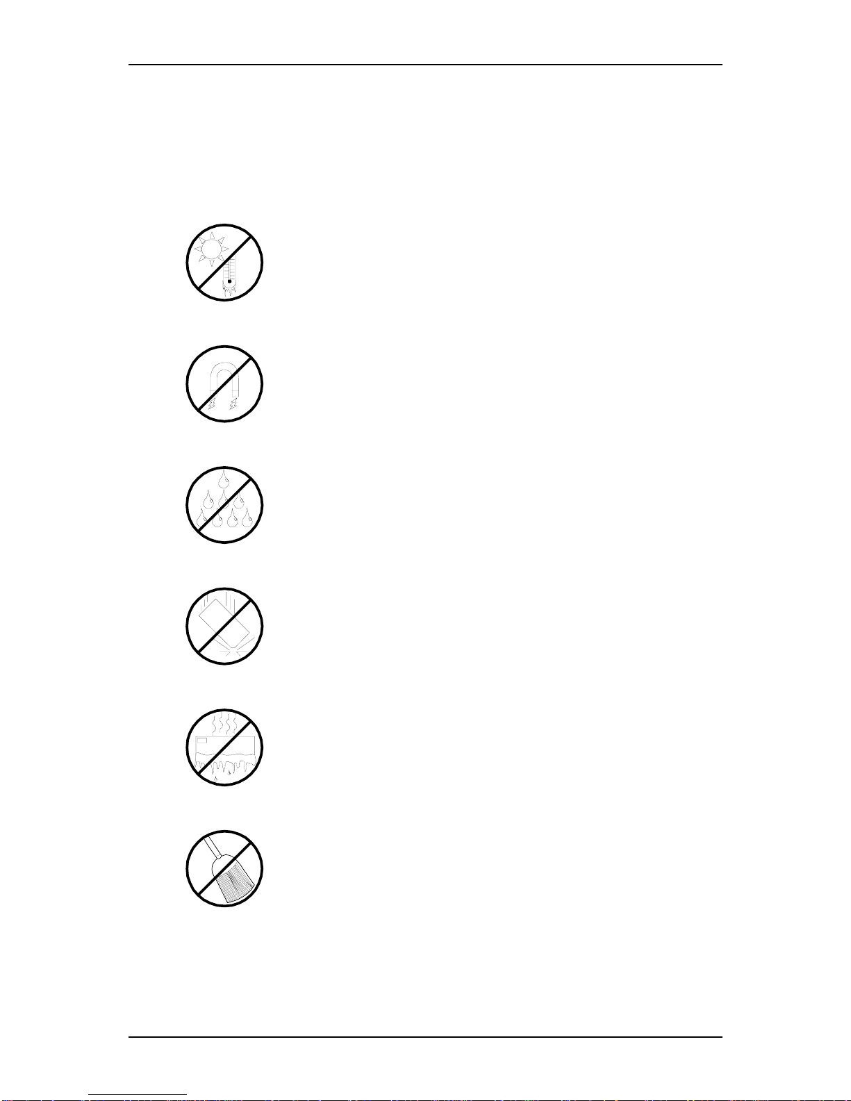
Use the following guidelines to properly handle and care for your system.
Protect the system from extremely low or high temperatures. Let
the system warm (or cool) to room temperature before using it.
Keep the system away from magnetic forces.
Keep the system dry. Do not wash the system with a wet cloth or pour fluid
into it.
Protect the system from being bumped or dropped.
Check the system for condensation. If condensation exists, allow it to
evaporate before powering on the system.
Keep the system away from dust, sand, and dirt.
Page 15

1
Server General Description
■ Server Overview
■ Server Chassis
■ Standard Features
■ Optional Features
■ Rack Version
100Syste m Over view
Page 16

NS170 User Guide - Server General Description
1 - 2
Server Overview
The NAS Server NS170 is based on the Intel® Pentium® 4 microprocessor family. It
offers the latest technology. The combination of compute performance, memory capacity, and integrated I/O provides a high performance environment for many server market applications. These range from large corporations supporting remote offices to
small companies looking to obtain basic connectivity capability such as file and print
services, e-mail, web access, web site server, etc. The NAS Server NS170 is housed
and available as a tower-based system. As application requirements increase, you can
expand your server with an additional memory, add-in boards and peripheral devices;
tape devices, CD-ROM, and hard disk drives.
Figure 1 - 1 : NS170
Your server features the following major components:
■ A high performance Intel® Pentium® 4 processor.
■ Up to 4GB of memory (using 1GB DIMMs). Minimum configuration is 256 MB
of memory.
■ Five integrated I/O expansion PCI slots for add-in boards (two 64-bit/66 MHz and
three 32-bit/ 33 MHz slots).
■ Onboard enhanced serial ATA RAID controller.
■ Onboard high-performance RAGE XL graphics accelerator.
■ Onboard 1000/100/10 network controller.
■ Integrated optical drive and 1.44MB diskette drive.
■ Four hard disks expansion bays.
■ One removable media expansion bay.
■ Embedded PC-compatible support (serial, parallel, mouse, keyboard, USB, LAN,
and video).
■ High degree of S-ATA hard disk drive fault tolerance and advanced disk array
management features through the use of RAID technology.
Page 17
NS170 User Guide - Server General Description
1 - 3
Server Chassis
Front View
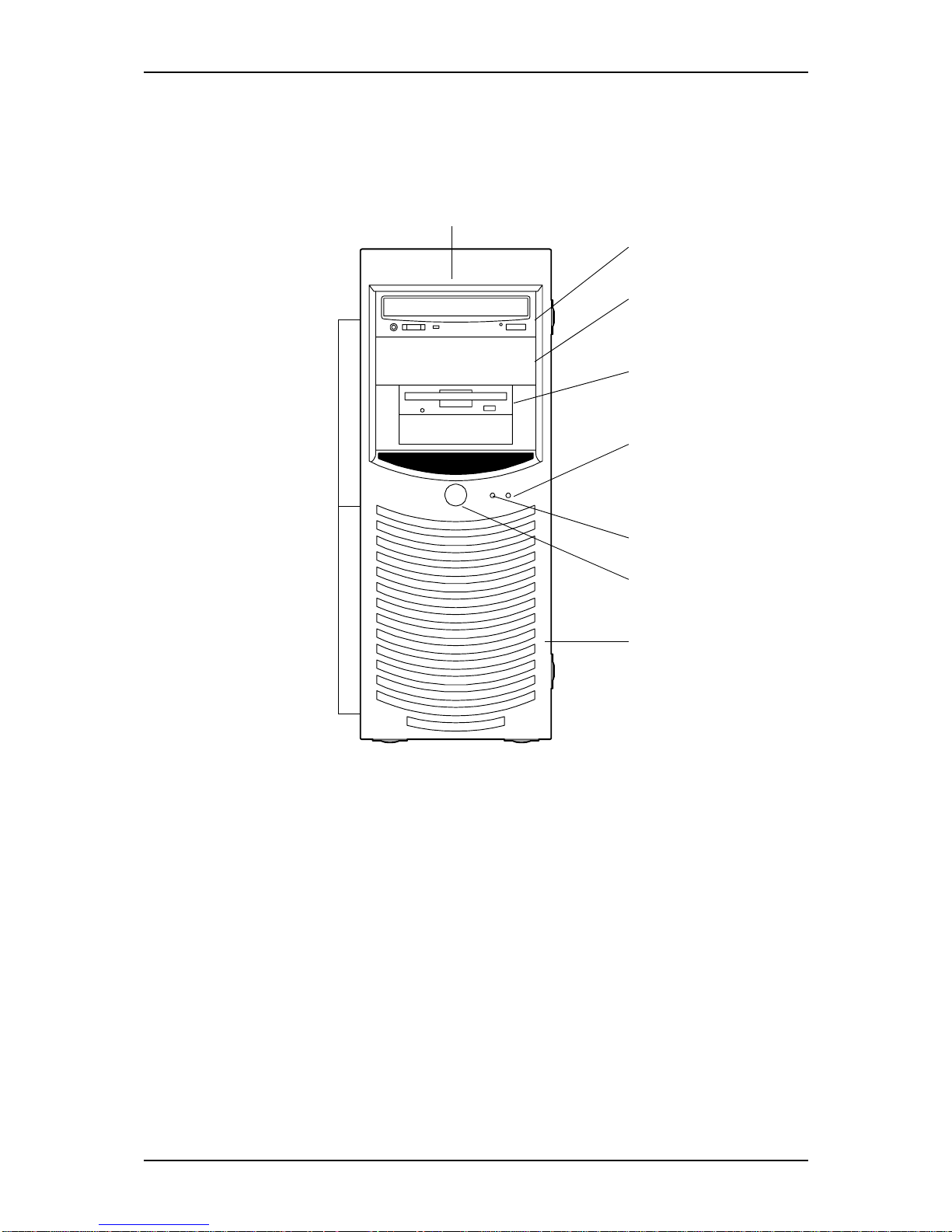
Figure 1 - 2 : NS170 Front View
1
2
3
4
5
6
7
8
9
Page 18

NS170 User Guide - Server General Description
1 - 4
1File bay
The file bay contains both a 5.25-inch device bay and a 3.5-inch device bay.
2 Optical drive
Each drive is equipped with the following:
- Tray eject button to eject the tray
- Access lamp that indicates the disk access status
- Emergency hole to forcibly eject the tray
3 5.25-inch device bay
Two 5.25-inch bays, one of which includes an optical drive.
A backup file may be installed in the other 5.25-inch device bay.
4 3.5-inch floppy disk drive
The floppy disk drive is equipped with the following:
- Eject button to eject the floppy disk
- Acces lamp that indicates the disk access status
5 Disk access lamp ( orange)
Lights up when a hard disk drive active, reading or retrieving data.
6 Status lamp (green)
Indicates whether the computer is on or off. A steady green lamp indicates the
computer is on. The lamp blinks green when the computer is in sleep mode.
7 Power button
Press this switch to turn on/off the power. Refer to the ‘Powering On Your Server’,
‘Powering Off Your Server’ and ‘Forcing a Power Shutdown’ sections hereafter for
details.
8
Front panel
The front panel protects the front face of the chassis
9
Release tabs
Press the release tabs to remove the front panel. See “Removing and Replacing the
Front Panel” on page 8.
Page 19

NS170 User Guide - Server General Description
1 - 5
Rear View
Figure 1 - 3 : NS170 Rear View
6 5 1
12 13
2
3
4
2
7
8
9
10
11
Page 20
NS170 User Guide - Server General Description
1 - 6
1 AC power connector
Connect the power cord to this socket.
2 Thumb screws
Secure the right side cover
3 Cable tie
Used to bundle the peripheral device cables (mouse and keyboard)
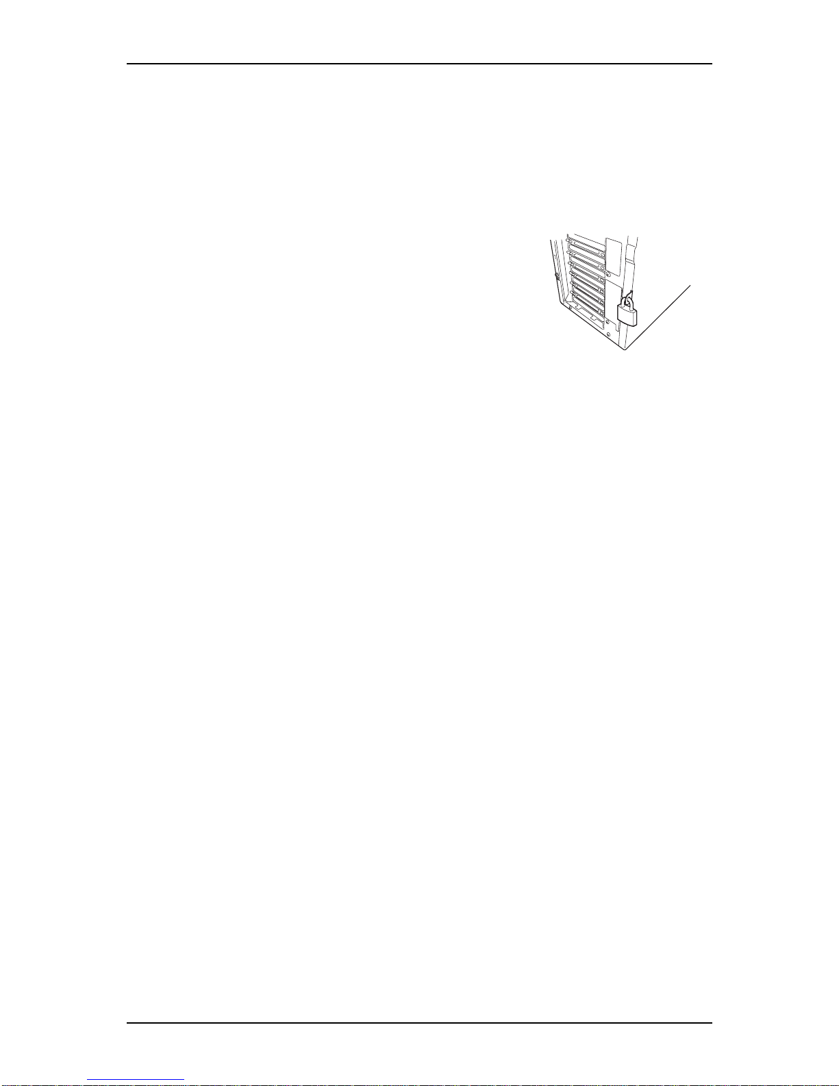
4 Cabinet lock
Installing a theft prevention device protects the internal components
from being stolen.
5 Mouse connector
Connect the mouse coming with the server to this socket.
6 Keyboard connector
Connect the keyboard coming with the server to this socket.
7 USB connectors
Connect devices accepting the USB interface to these sockets.
8 Serial port connector
Connect devices accepting the serial interface to this socket.
The server cannot be directly connected to a leased line through the
connector.
9 Printer port connector
The printer port connector can be connected to a printer with the
Centronics interface.
10 Monitor connector
Connect the display unit to this socket.
11 LAN connector
Use the LAN connector to connect the system to the network
(1000BASE-T/ 100BASE-TX/ 10BASE-T).
The value following the bold-faced number indicates the port
number.
12 1000/100/10 lamp
The 1000/100/10 indicates the LAN transfer rate
13 Link/ACT lamp
The link/ACT lamp shows the LAN access status
Page 21
NS170 User Guide - Server General Description
1 - 7
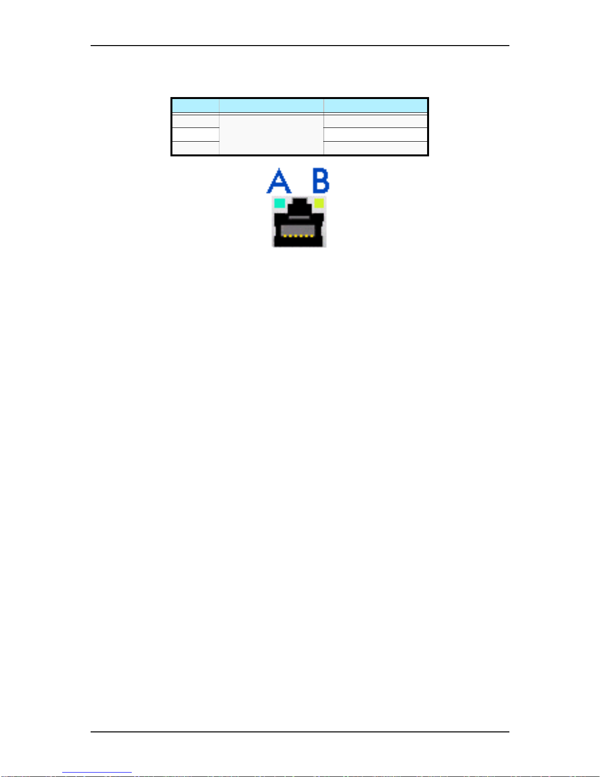
RJ45 Leds
Figure 1 - 4 : RJ45 Leds
Table 1 - 1: RJ45 Leds Activity
Speed Led A Activity Led B Activity
10 Lights ON (green)
when active
OFF
100 ON (green)
1000 ON (orange)
Page 22
NS170 User Guide - Server General Description
1 - 8
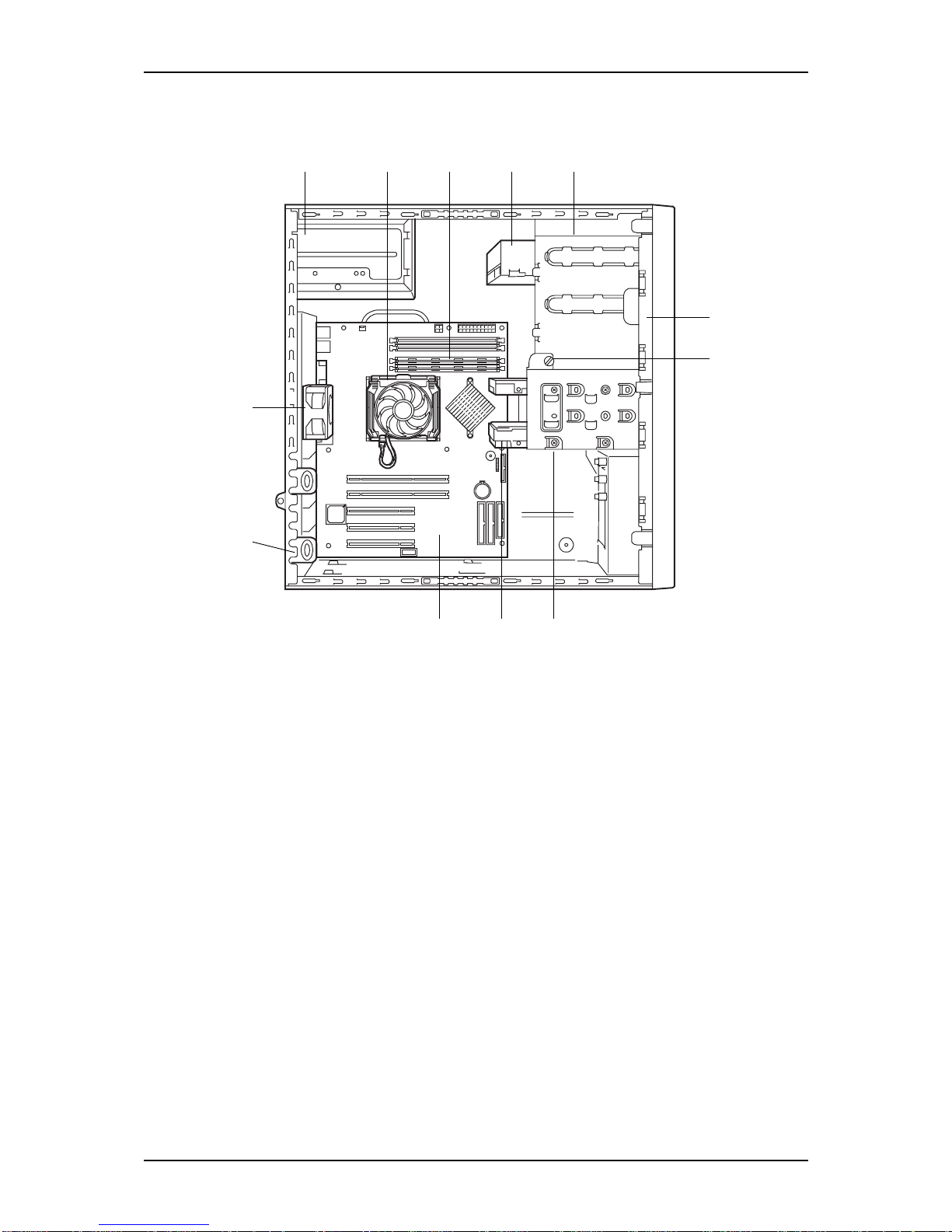
Internal View
Figure 1 - 5 : NS170 Internal View
1 Power supply
2 Processor cooling heatsink (mounted on the processor)
3DIMMs
4 CD-ROM drive
5 File bay
An optical drive and a floppy disk drive are installed. The standard device bay can include a
maximum of two 5.25-inch devices and two 3.5-inch device
6 3.5-inch floppy disk drive
7 Device bay fixing screw
To remove the hard disk drive bay, loosen and then remove this screw.
8 Hard disk drive bay
The hard disk drive bay can be equipped with 4 hard disk drives maximum.
9 Hard disk drive (optional)
10 Motherboard
11 PCI board retention spring
12 Rear cooling fan
1 2 3 4 5
10 9 8
6
7
12
11
Page 23
NS170 User Guide - Server General Description
1 - 9
Motherboard
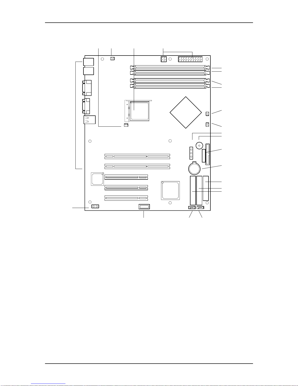
Figure 1 - 6 : NS170 Motherboard
1 Heat sink fan connector
2 Rear cooling fan connector
3 Processor socket
4 Power connectors
5 DIMM sockets
6 Hard disk drives cooling fan connectors
7
8 Configuration jumper switch (CMOS/Clear)
9 Speaker
10 Front panel interface connector
11 Lithium battery
12 Floppy disk drive connector
13 Ultra ATA100 connector
(primary, for optical drives)
5-#4
5-#3
5-#2
5-#1
6
7
8
9
10
11
12
13
14
19
18
17-#1
17-#2
17-#3
17-#4
17-#5
1 2 3 4
16 15-#1 15-#2
Page 24

NS170 User Guide - Server General Description
1 - 10
14 Ultra ATA100 connector
(secondary, for tape drive if any)
15 Serial ATA connectors
16 USB connector (not used)
17 PCI board slots
Slots 17 - #1 and #2:
64-bit/66 MHz, PCI, 3.3V
Slots17 - #3 to #5:
32-bit/33 MHz, PCI, 5.0V
18 LED connector
19 External connection connector
Page 25

NS170 User Guide - Server General Description
1 - 11
Standard Features
High performance
■ Intel® Pentium® 4 Processor
■ High-speed
1000BASE-T/100BASE-TX/10BASE-T
interface (1Gbps/100Mbps/10Mbps
supported)
■ Serial ATA 180
High reliability
■ Memory monitoring feature (single-bit
error correction/double bit error
detection)
■ Temperature detection
■ Processor fan monitoring feature
■ Internal voltage monitoring feature
■ BIOS password feature
■ Embedded serial ATA RAID drive
configuration feature
■ Optional SCSI and S-ATA RAID
controllers
Management utilities
■ NEC ESMPRO
■ Off-line Maintenance Utility
Power Saving Feature
■ Sleep feature (available for Windows
Server 2003/ Windows 2000)
Expandability
■ Five integrated I/O expansion PCI slots
(two 64-bit/ 66 MHz)
■ Large memory of up to 4GB (four 1GB
DIMMs)
■ Four hard disk drive bays
■ USB 2.0 interface
Many available features
■ Graphic accelerator “RAGE XL”
support
■ El Torito Bootable CD-ROM (no
emulation mode) format support
■ Remote power-on feature
■ AC-LINK feature
Self-diagnosis
■ Power On Self-Test (POST)
■ Test and Diagnosis
Easy and Fine Setup
■ Recovery CD
■ Maintenance/Administration CD
Page 26

NS170 User Guide - Server General Description
1 - 12
Remote Power-On Feature (Wake On LAN)
The remote power-on function turns on the server through a network. It sends a special
packet from the management computer to a remote server to turn it on if the server is
off-powered.
To enable this feature, you must select “Enabled” for each submenu in the Power Management Setup of the Advanced menu of the BIOS setup utility, “SETUP”.
The remote power-on feature is not available in the following cases:
■ Abnormal previous system shut-down
■ No power supply to the server (due to turned-off breaker, disconnected power cord,
power blackout, etc.)
AC-LINK Feature
When the power cord of the server is connected to an uninterruptible power supply
(UPS) unit, the server supports the power linkage feature that enables control over the
power supply from the UPS to the server. The AC-LINK feature can be enabled or disabled with the Power Mangement Setup in the Server menu of the BIOS setup utility.
Refer to chapter 3 for details.
Security
The BIOS setup utility feature provides a number of security features to prevent unauthorized or accidental access to the system. Once the security measures are enabled,
access to the system is allowed only after the user enters the correct password(s). For
example:
■ Set and enable an administrative password.
■ Set and enable a user password.
■ Check the user account when entering the BIOS setup utility or booting the system.
NEC ESMPRO
The NEC ESMPRO is a server management software that runs on the OS. The NEC
ESMPRO includes the NEC ESMPRO Manager for the server monitoring terminal
and the NEC ESMPRO Agent for the NEC Express server.
Off-line Maintenance Utility
The Off-line Maintenance Utility is used for proactive maintenance.
Page 27

NS170 User Guide - Server General Description
1 - 13
Power Supply
The server contains one auto-sensing 300-watt power supply at an operating frequency
of 50/60 Hz.
The power supply is designed to comply with existing emission standards and provide
sufficient power for a fully loaded system configuration.
Peripheral Bays
The server supports a variety of standard PC AT-compatible peripheral devices. The
chassis includes these peripheral bays:
■ Two 3.5-inch file bays for installing the standard 3.5-inch floppy disk drive (sup-
ports 720 KB and 1.44 MB floppy disk media) or an optional file device.
■ Two 5.25-inch file bays for installing half-height 5.25-inch peripheral devices such
as an optional tape drives (An optical drive is factory-installed).
■ The hard disk drive bays for installing up to four S-ATA hard disk drives.
Page 28

NS170 User Guide - Server General Description
1 - 14
Optional Features
You will find hereafter information about the optional components that may be
installed in your system.
With Enhanced Cage
■ Three 5.25-inch file bays for installing the standard 3.5-inch floppy disk drive in a
converter (supports 720 KB and 1.44 MB floppy disk media) and optional file
devices.
■ One slim CD-ROM drive.
S-ATA Configuration
The hard disk drive bays for installing up to four S-ATA hard disk drives.
Page 29
NS170 User Guide - Server General Description
1 - 15
Rack Version
This section applies only to the rack version of your server.
Specifications
The rack version of your system features an Intel Pentium 4 Northwood processor of a
minimum of 2.8 GHz.
Caution
Intel Pentium 4 Prescott processors are not supported.
Using an Intel Pentium 4 Prescott processor may cause
overheating and result in system damage.
Removing the Rack Front Bezel
Caution
Observe the safety precautions
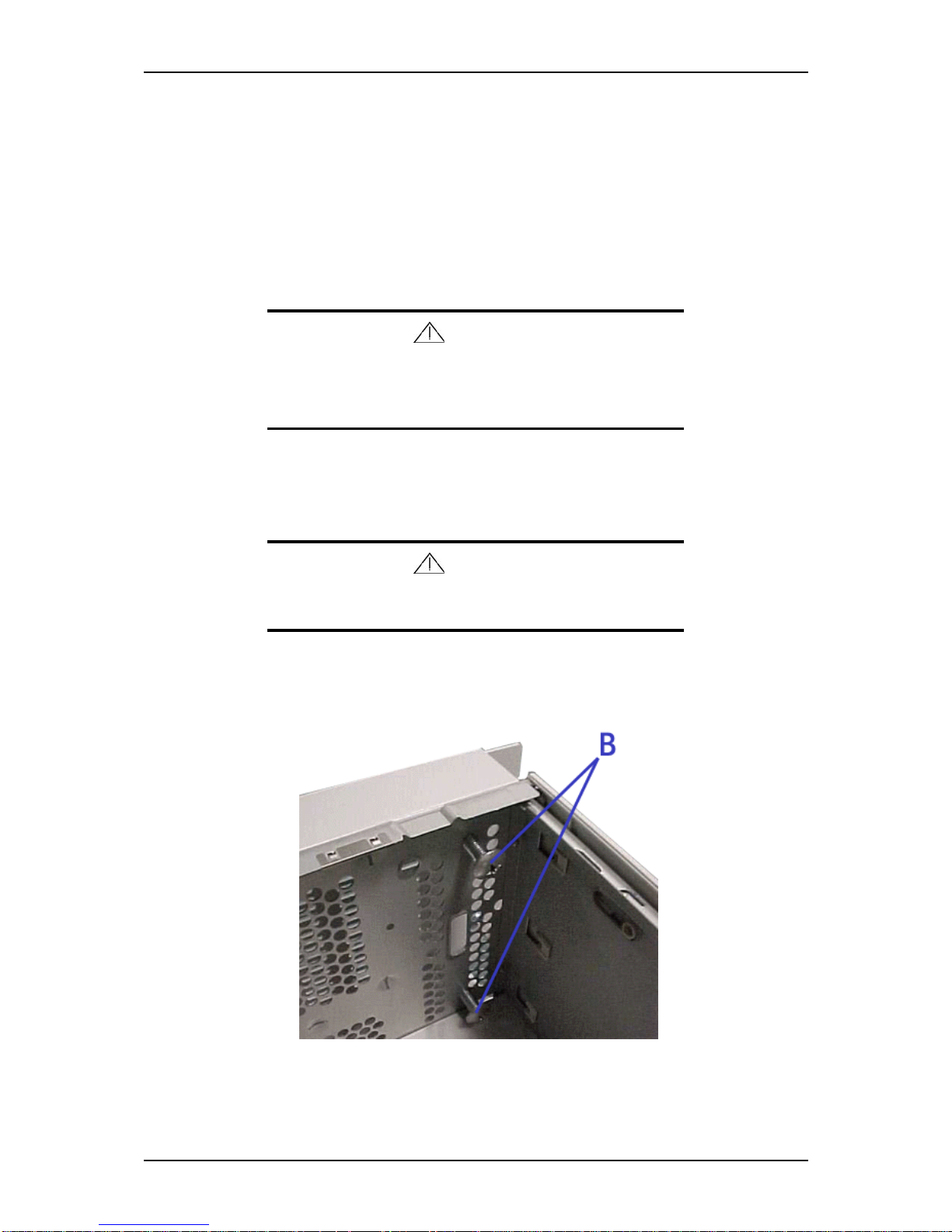
1. Remove the top cover (right side door). See “Removing or Installing the Right
Side Door” on page 4
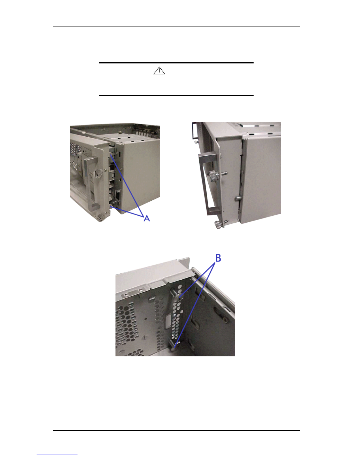
2. Remove the screws (B) securing the bezel to the frame.
Figure 1 - 7 : Removing the Screws
Page 30
NS170 User Guide - Server General Description
1 - 16
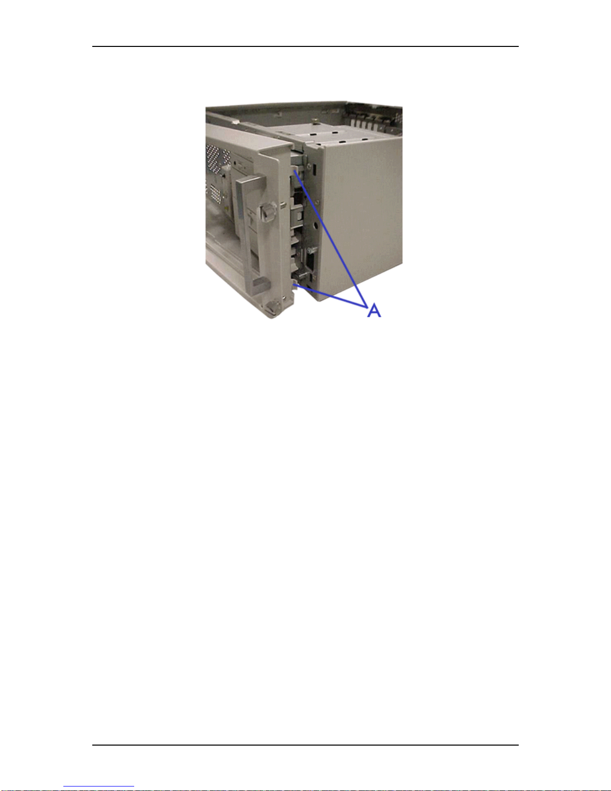
3. Open the Front Bezel pulling on the handle and remove the tabs (A) from the
frame as shown on the picture.
Figure 1 - 8 : Removing the Front Bezel
Your server is now ready to be upgraded.
Page 31
NS170 User Guide - Server General Description
1 - 17
Installing the Rack Front Bezel
Caution
Observe the safety precautions
1. Position the Front Bezel as shown on the pictures. The tabs (A) should click
into their respective slots.
Figure 1 - 9 : Positioning the Front Bezel
2. Fix the bezel to the frame with the screws (B) provided in the rack-mount kit.
Figure 1 - 10 : Fixing the Bezel
3. Replace the right side door. See “Removing or Installing the Right Side Door”
on page 4
Your server is ready to be reinstalled into a standard IAE 19-inch rack cabinet. Refer to
the ‘Rack Installation Guide’ documentation delivered with your server for instructions
and details.
Page 32

Page 33

2
Setting Up Your Server
■ Overview
■ Selecting a Site
■ Unpacking the Server
■ Making Connections
■ Connecting the Power Cord
■ Using the Server
Page 34

NS170 User Guide - Setting Up Your Server
2 - 2
Overview
This chapter describes how to select a site, unpack the server, make cable connections,
and power on the system units. Information on front and rear panel features, switches
and LEDs are also included in this chapter.
Page 35
NS170 User Guide - Setting Up Your Server
2 - 3
Selecting a Site
The server operates reliably in a typical office environment.
Choose a site that is:
■ Near grounded, three-pronged power outlets.
Note: For the United States and Canada, this means a
NEMA 6-15R outlet for 200-240 VAC. The system cannot be
used on a NEMA 5-15R outlet for 100-120 VAC. For other
international sites, this means three-pronged power outlets
applicable for the electrical code of the region.
Warning
Be sure the power service connection is through a properly
grounded outlet.
■ Clean, dust-free, and well ventilated. Every side ventilating openings kept free of
obstructions. Away from sources of heat, vibration or physical shock.
■ Isolated from strong electromagnetic fields and electrical noise produced by
electrical devices (such as air conditioners, large fans, large electric motors, radio
and TV transmitters, and high-frequency security devices)
■ Spacious enough to provide at least ten inches (25 centimeters) in front of the
system, five inches (13 centimeters) behind the system and three inches (eight
centimeters) on each side of the system for proper cooling, airflow, and cable
clearance.
Caution
Make sure to leave enough space behind the server (three
inches - eight centimeters).
Not doing so may result in overheating and damaging the
server.
■ Easily accessible for server maintenance and installation of server upgrades.
Page 36

NS170 User Guide - Setting Up Your Server
2 - 4
Unpacking the Server
When you receive your server, inspect the shipping containers prior to unpacking. If
the shipping boxes are damaged, note the damage, and if possible, photograph it for
reference. After removing the contents of the containers, keep the cartons and the
packing materials. If the contents appear damaged when you unpack the boxes, file a
damage claim with the carrier immediately.
Page 37
NS170 User Guide - Setting Up Your Server
2 - 5
Making Connections
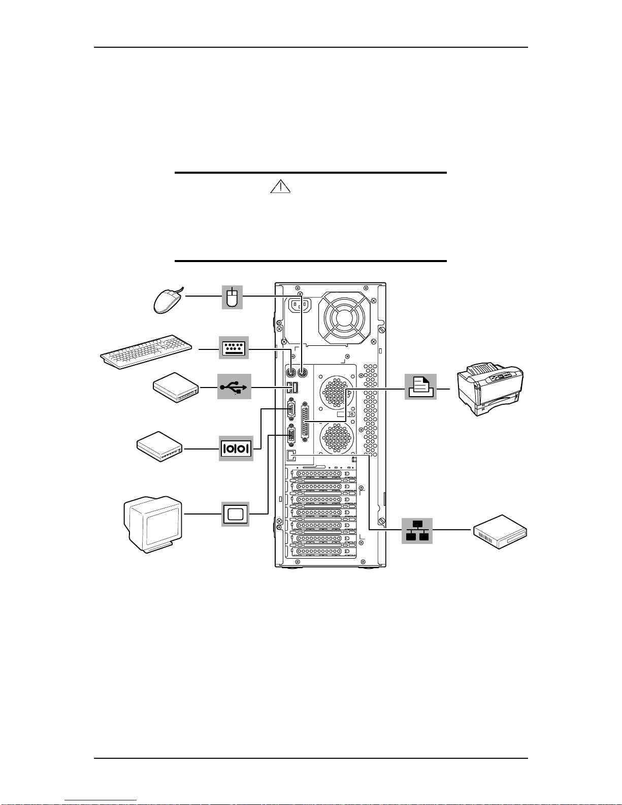
Connect your keyboard, monitor, and mouse. Also connect any external peripheral
devices such as a printer or scanner by following the instructions included with these
devices.
Caution
Damage to the system may result if the keyboard/ mouse cable
is inserted or removed when power is applied to the system.
Inserting a telephone line connector into a LAN RJ-45 port may
result in personal injury and equipment damage.
Figure 2 - 1 : Connecting Peripheral Devices
Page 38
NS170 User Guide - Setting Up Your Server
2 - 6
Connecting the Power Cord
Plug the female end of the AC power cord into the input receptacle on the rear of the
power supply cage. Plug the male end of the power cord into NEMA 5-15R outlet for
100-120 VAC, or CEE7, or UK outlet for 200-240 VAC.
If the power cord(s) supplied with the system is not compatible with the AC wall outlet
in your region, obtain a suitable power cord that meets the following criteria.
■ The power cord must be rated for the available AC voltage and have a current
rating that is at least 125% of the current rating of the system.
■ The power cord connector that plugs into the wall outlet must be terminated in a
grounding-type male plug designed for use in your region. It must have
certification marks showing certification by an agency acceptable in your region.
■ The power cord connector that plugs into the server must be an IEC- type CEE-22
female connector.
Warning
Your server shipped with a power cord for the power supply.
Do not attempt to modify or use the supplied AC power cord if it
is not the exact type required.
Page 39

NS170 User Guide - Setting Up Your Server
2 - 7
Using the Server
The following subsections describe how to use this server system properly and safely,
including an explanation of the server system power on/off sequences, what the POST
program checks in the server, and how to perform a forced power shutdown.
When using the server system the following precautions should be observed.
■ Make sure you power off the server before connecting or disconnecting cables
between the server and peripheral devices. Connecting or disconnecting the cables
while the server is powered on may cause malfunction or failures within the server.
■ Verify that the access lamp on the diskette drive is unlit before turning off the
server or ejecting the floppy disk. Turning off the server or ejecting the floppy disk
while the access lamp is lit may damage data being stored on the floppy disk.
■ After turning off the server, wait at least 10 seconds before turning it on again.
Cycling the power immediately may cause malfunction or failures of the server.
■ Before relocating the server, turn off the power and unplug the power cord from
the outlet. Moving the server when it is powered may cause malfunction or failures
of the server.
■ Clean the server regularly. Regular cleaning prevents failures of the server and its
components.
■ Lightning may cause a momentary voltage drop. To prevent this problem, an
uninterruptible power supply unit is recommended.
■ Only use options qualified for the server. A non-qualified option may be mounted
or connected to the server, but it may fail to operate normally or even cause failures. These types of failures are not covered under warranty.
Page 40
NS170 User Guide - Setting Up Your Server
2 - 8
Powering On Your Server
Caution
■ If the power cord is connected to a power control device
such as a UPS (Uninterruptive Power Supply), make sure
that the power control device is powered.
■ Do not turn off the server until characters following the Boot-
BIOS logo appears on the screen.
To power on your server:
1. Make sure all external devices, such as a video display, keyboard, and mouse
(optional) have been connected, and the power cords are connected.
2. Power on the video display and any other external devices.
Note: If the server power cord(s) is connected to a power
control unit such as an UPS (Uninterruptible Power Supply)
make sure that the power control unit is powered on.
3. Press the POWER switch on the front of the server chassis.
The POWER lamp lights green. If it is not lit, ensure the AC power cord is
connected to a functional ac power source.
After a few seconds your system begins the internal Power-On Self Tests (POST).
POST automatically checks the system board, CPU(s), memory, keyboard, mouse, and
most installed peripheral devices. POST also displays the start messages of the BIOS
setup utility during execution.
The POST check results should be checked in the following cases:
■ When the server is being used for the first time.
■ When the server appears to fail.
■ When the server beeps many times between power-on and OS start-up.
■ When an error message appears on the screen.
Page 41
NS170 User Guide - Setting Up Your Server
2 - 9
Note: For error messages that appear on the display unit,
refer to subsection POST Error Codes and Messages in
Chapter 5 of this Guide.
Caution
Always allow POST to complete before powering down your
server.
If you have problems powering on your server, refer to Problem Solving in Chapter 5.
Powering Off Your Server
When server power is on, pressing the power on/off switch on the front panel of the
server turns the power off.
To turn the server off:
1. Shutdown the operating system (OS).
2. If necessary, press the POWER switch on the front of the server chassis again
to power off the system.
The POWER lamp lights off.
3. Power off the peripheral devices.
Note: If the server power cord is connected to a power
control unit such as an UPS (Uninterruptible Power Supply),
refer to the UPS user's guide for proper power-off procedures.
Forcing a Power Shutdown
A forced power shutdown can be used when the power on/off switch does not power
off the server or the reset functions do not work.
To perform a forced power shutdown:
■ Press in on the power on/off switch located on the front panel of the server for at
least 4 seconds to force the server power off.
To power on after a forced shutdown, wait 10 seconds and then power on again.
Page 42

Page 43

3
Configuring Your Server
■ Overview
■ BIOS Redirection Console
■ BIOS Setup Utility
■ SCSISelect Utility
■ RAID Configuration Utility
■ Configuring MotherBoard Jumpers
Page 44

NS170 User Guide - Configuring Your Server
3 - 2
Overview
Configuration and setup utilities are used to change your server configuration. You can
configure your server, as well as option boards you may add to your server, using the
BIOS Setup Utility. Several unique system parameters are configured using the BIOS
Setup, which is stored in the system FLASH memory.
If your server has been factory configured, the BIOS Setup Utility does not need to be
run unless you want to change the password or security features, add certain types of
option boards or devices, or upgrade your server board.
This chapter also provides information on several system configuration parameters that
are set by jumpers on the server board. However, these parameters do not usually
require change.
Page 45
NS170 User Guide - Configuring Your Server
3 - 3
BIOS Redirection Console
This chapter describes how to setup the BIOS Redirection Console feature.
Definition
The BIOS redirection Console is a feature implemented in the BIOS of the
motherboard of your NS170.
It allows you to see on a second machine, everything located on the screen of the
NS170 during the booting phase.
When the boot phase reaches the Windows 2003 logo, the BIOS redirection console
stops displaying live information.
Note: The BIOS Redirection Console only works when the
processor is running in real mode and stops functioning when it
goes in protected-mode.
Requirements
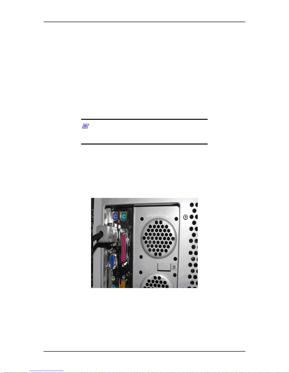
A NULL MODEM serial cable is required to connect your NS170 to a client through
its serial port.
Use COM1 located on the rear panel to connect your client to the NEC Storage NS170.
Figure 3 - 1 : COM1 on the NS170 Rear Panel
Page 46
NS170 User Guide - Configuring Your Server
3 - 4
HyperTerminal Configuration
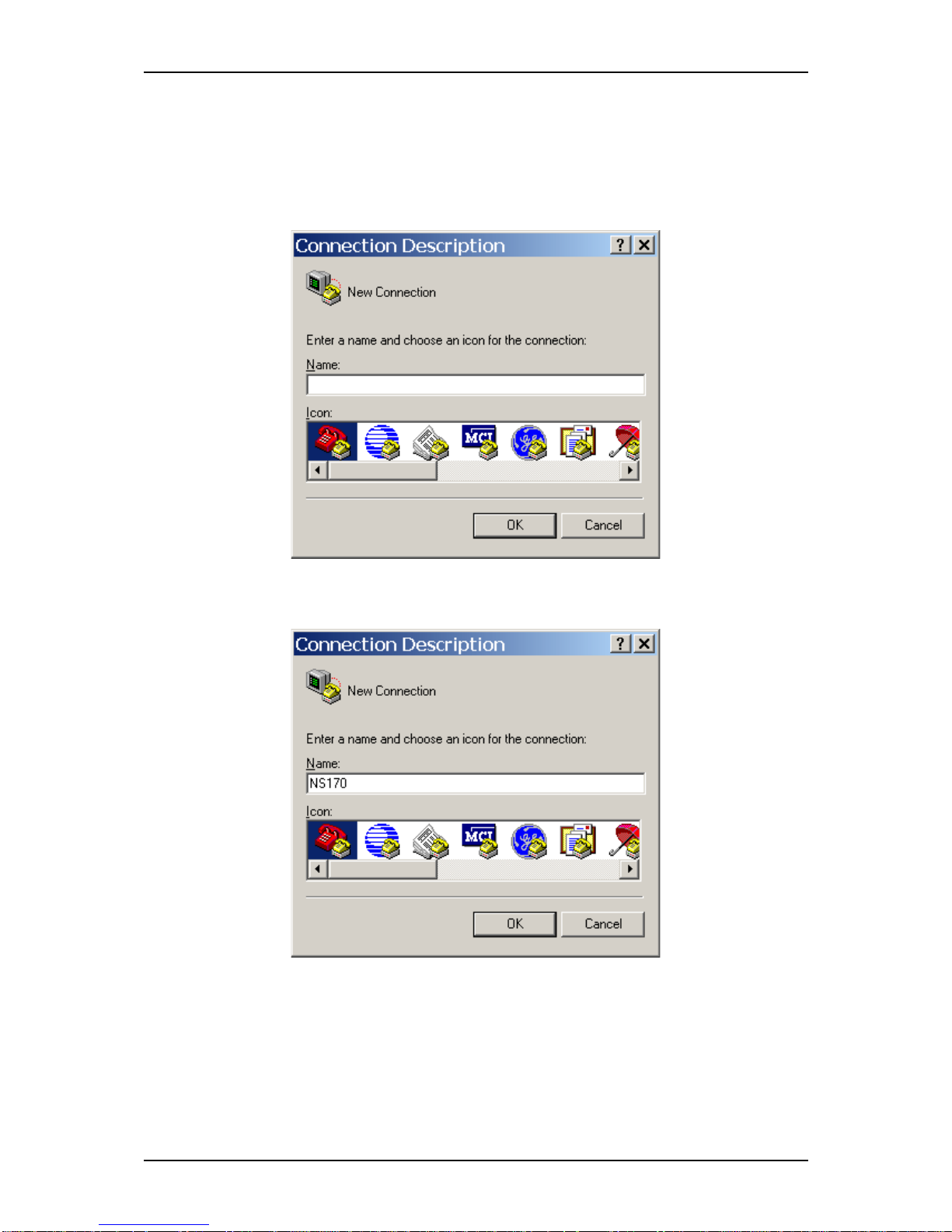
To configure HyperTerminal:
1. In Programs/Accessories/Communications launch HyperTerminal.
After a few seconds, the Connection Description dialog box opens.
2. In the Connection Description dialog box, type the name of the connection,
NS 170 for example.
Page 47
NS170 User Guide - Configuring Your Server
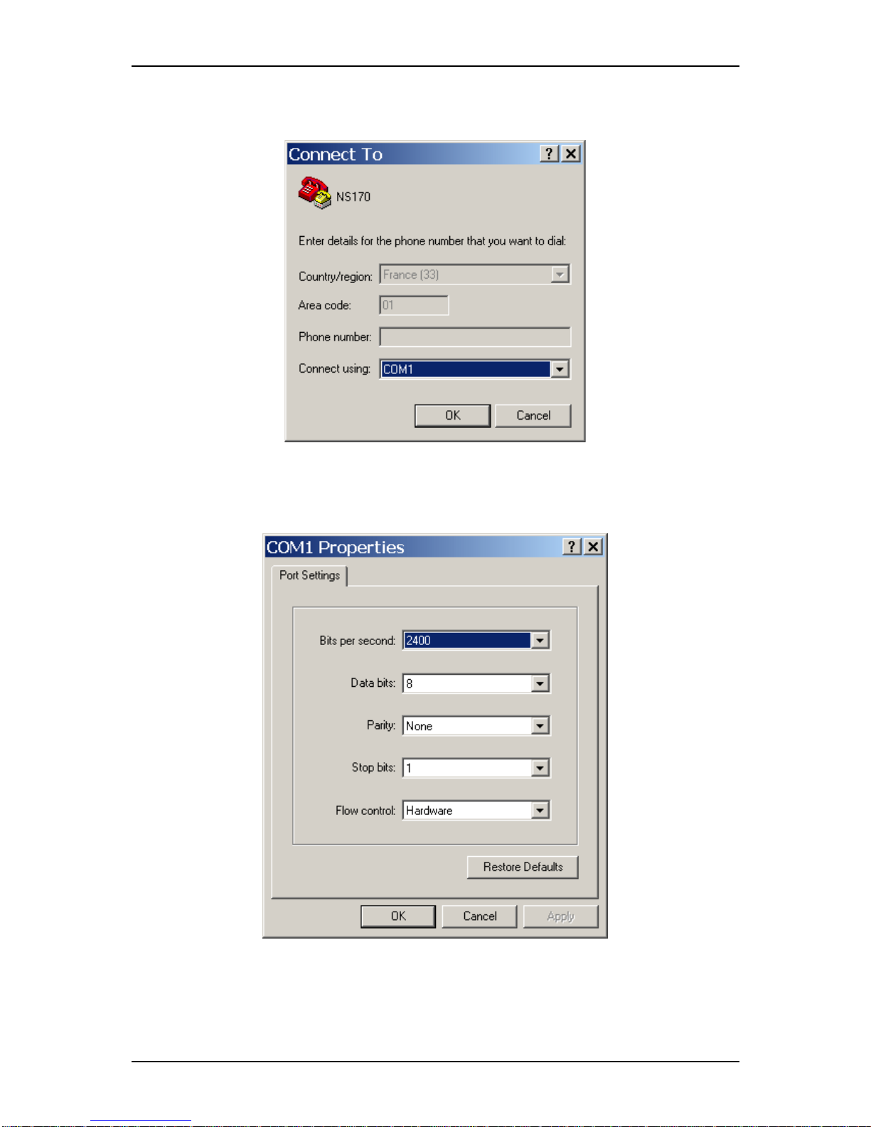
3 - 5
3. Choose an icon for the connection then click [OK].
The Connect To dialog box opens.
4. Select the COM port used on your second machine, for example COM1.
5. Click [OK].
The COM1 Properties dialog box opens.
Page 48
NS170 User Guide - Configuring Your Server
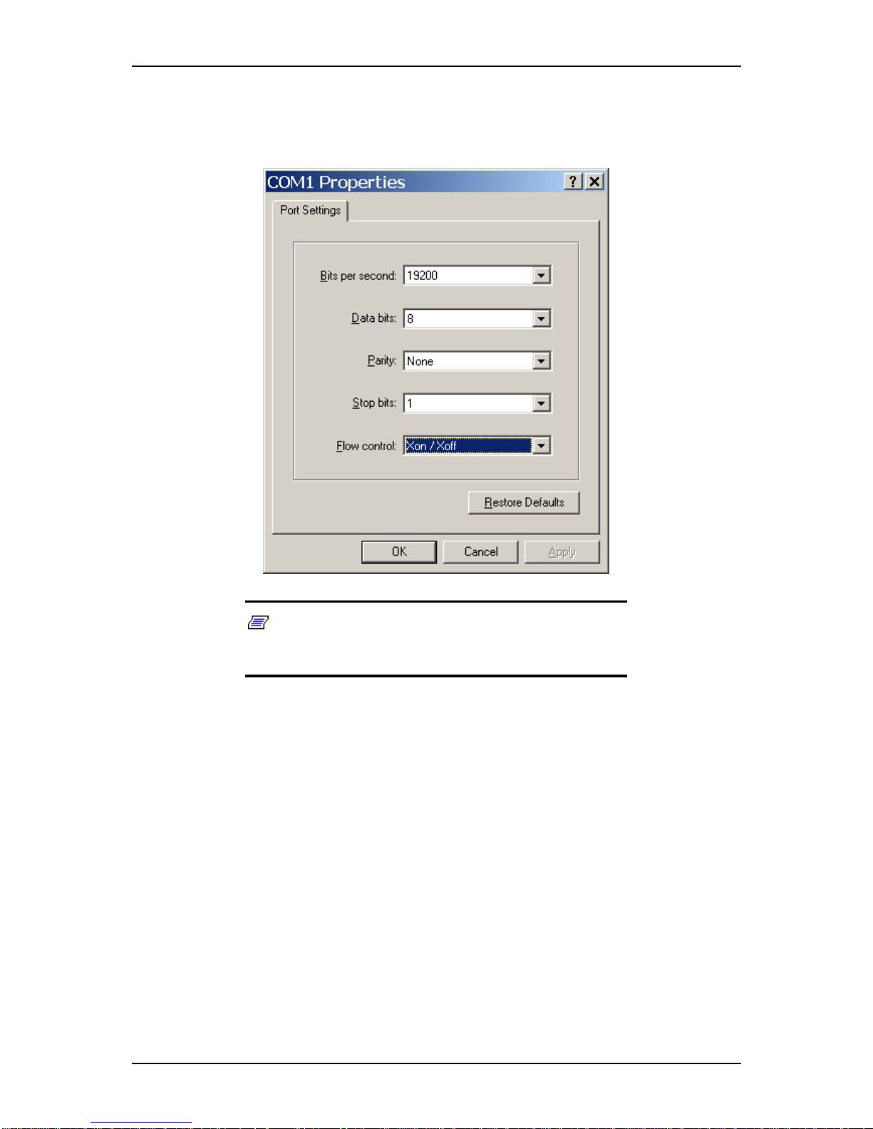
3 - 6
6. To configure the connection, enter the following parameters:
- Bits per second: 19200
- Flow control: Xon/Xoff.
Note: When you modify your serial connection speed,
setup the speed in the BIOS of the NS170 then modify it in the
HyperTerminal connection.
Page 49
NS170 User Guide - Configuring Your Server
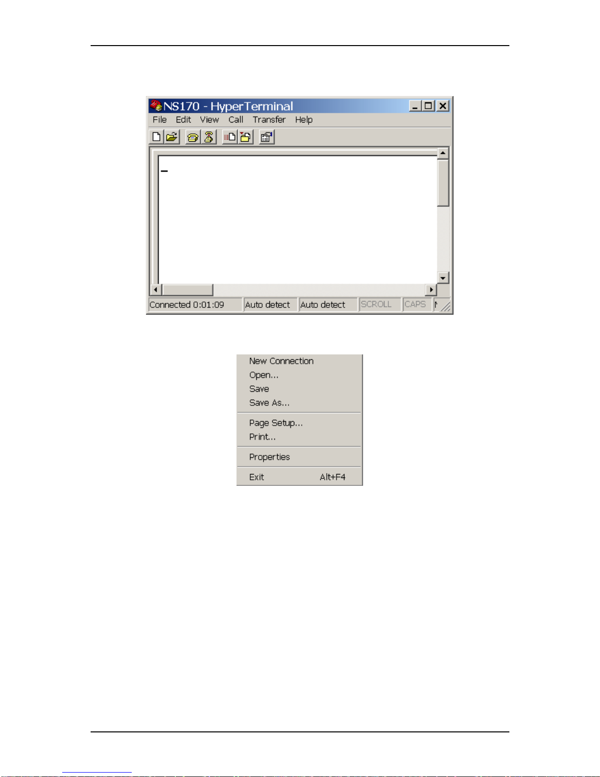
3 - 7
7. Click [OK].
The NS170 HyperTerminal windows opens.
8. In the menu click File.
The pull-down File menu unrolls.
Page 50
NS170 User Guide - Configuring Your Server
3 - 8
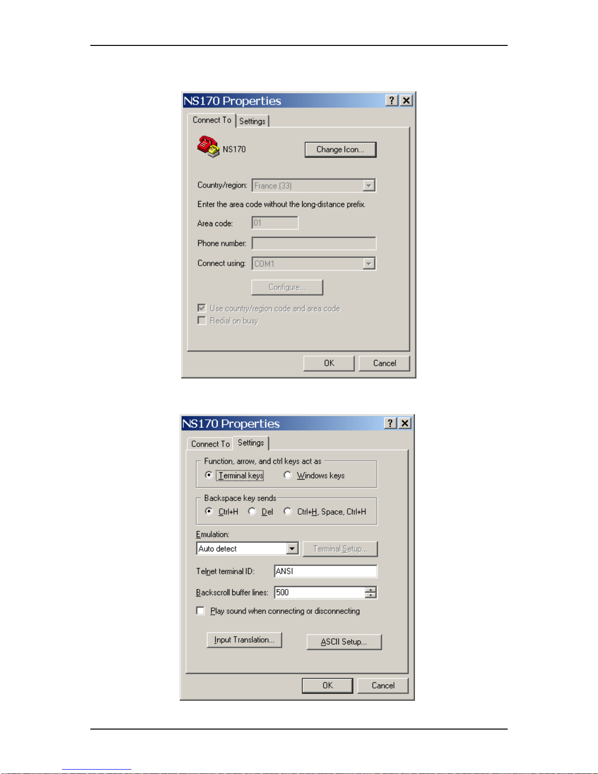
9. Click Properties.
The NS170 Properties dialog box opens.
10. Click the Settings tab.
The Settings tab opens.
Page 51
NS170 User Guide - Configuring Your Server
3 - 9
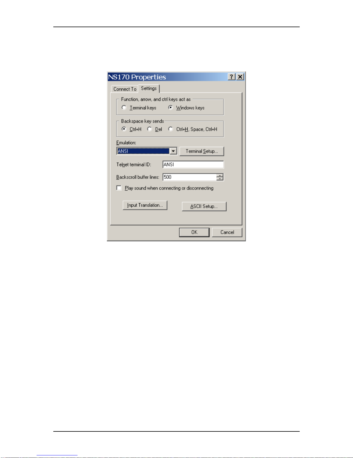
11. Set up as following:
- Function, arrow, and ctrl keys act as: Windows Key
- Emulation: ANSI
Page 52
NS170 User Guide - Configuring Your Server
3 - 10
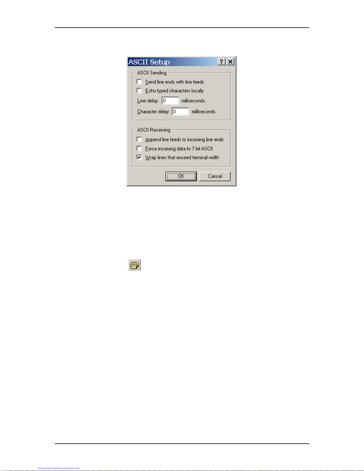
12. Click on [ASCII Setup...].
The ASCII Setup dialog box opens.
13. In the ASCII Receiving area unmark "Wrap lines that exceed terminal width"
then click [OK].
The ASCII Setup dialog box closes.
14. In the NS170 Properties dialog box click [OK].
The NS170 Properties dialog box closes.
15. Click [OK].
The ASCII Setup dialog box closes.
16. To enable the serial connection, in the HyperTerminal main window, click on
the CALL icon .
The BIOS boot screens is displayed.
Page 53
NS170 User Guide - Configuring Your Server
3 - 11
BIOS Setup Utility
The BIOS Setup Utility is used to change server configuration parameters. The utility
is resident in the system FLASH memory and does not require a diskette or an
operating system present to run.
Using the BIOS Setup Utility
You access the BIOS Setup utility when you turn on or reboot your server.
To run the BIOS Setup Utility:
1. Power-on or reboot the system. “Press <F2> to enter SETUP” displays.
2. Press F2. The BIOS Setup Utility starts and the Main Menu is displayed. The
menu bar at the top of the Main Menu lists the following selections:
Use the arrow keys to select a menu or an item on a displayed menu. Press the value
keys (listed in the table below) to cycle through the allowable values for the selected
field. Use the Exit menu’s “Save Values” selection to save the current values on all the
menus.
To display a submenu, position the cursor on a selection that has a submenu and press
ENTER. An arrow precedes selections with submenus.
Refer to the following table for information on the keys that you use with BIOS Setup.
These keys are also listed at the bottom of the Setup menu.
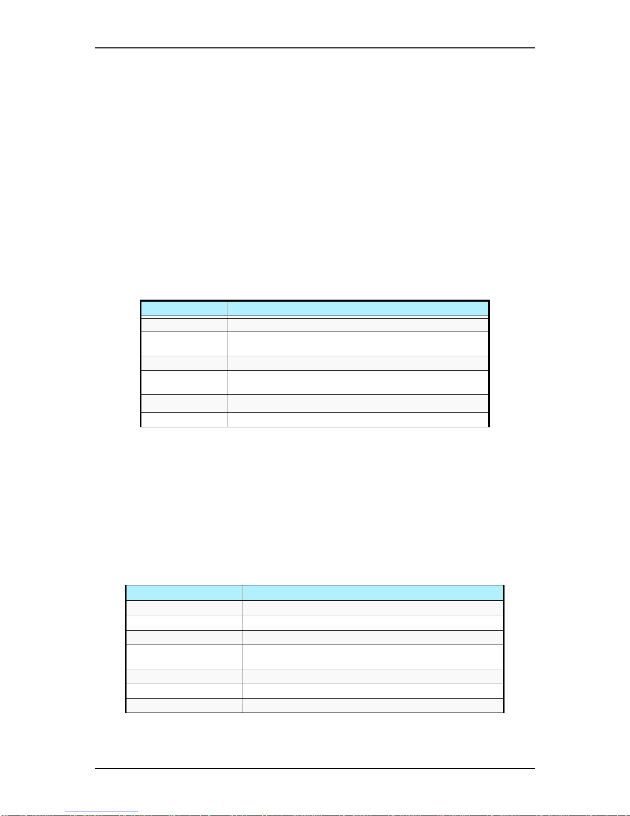
Table 3 - 1: Main Menu
Menu Use
Main Use this menu for basic system configuration.
Advanced Use this menu for setting the Advanced Features available on
your system.
Security Use this menu for setting passwords.
Server Use this menu to configure server specific options, the redirection
console and to display server information.
Boot Use this menu to configure Boot Device priority.
Exit Exits the current menu.
Table 3 - 2: BIOS Setup Keys
Key Function in Setup Menu
F1 or Alt-H Get Help about an item.
ESC Exit the current menu and return to the previous menu.
Left or right arrow keys Move between menus.
Up or down arrow keys Move cursor up and down. The cursor moves only to the settings
that you can change.
F9 Load default configuration values for this menu.
F10 Save configuration values and exit.
ENTER Execute command or Select ✟ submenu.
Page 54
NS170 User Guide - Configuring Your Server
3 - 12
BIOS Setup Configuration Settings
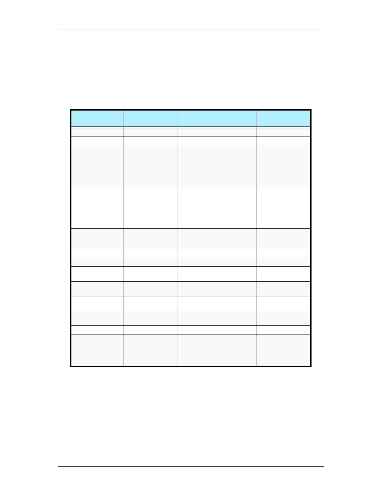
The BIOS Setup Configuration tables show the default settings for the BIOS Setup
Utility and provide a place for you to record any changes you make to these settings.
Recommended values are bold in the following tables.
Main Menu and Submenus
Table 3 - 3: Main Menu
Feature Choices or
Display Only
Description Your Setting
System Time HH:MM:SS Set the System Time.
System Date MM/DD/YYYY Set the System Date.
Legacy Diskette A Disabled
360 KB 5
¼”
1.2 MB 5
¼”
720 KB 3½”
1.44/1.25 Mb 3½”
2.88 MB 3½”
Select floppy disk drive type
Legacy Diskette B Disabled
360 KB 5
¼”
1.2 MB 5
¼”
720 KB 3½”
1.44/1.25 Mb 3½”
2.88 MB 3½”
Select floppy disk drive type
Hard Disk PreDelay
Disabled
3, 6, 9, 12, 15, 21,
30 Seconds
Allows to add a delay before
the first access of a hard disk
drive by the BIOS.
Primary IDE Master Selects sub-menu
Primary IDE Slave Selects sub-menu
Secondary IDE
Master
Selects sub-menu
Secondary IDE
Slave
Selects sub-menu
Serial ATA Channel
0 Master
Selects sub-menu
Serial ATA Channel
1 Master
Selects sub-menu
Processor Settings Selects sub-menu
Language English (US)
Français
Deutsch
Español
Italiano
Select the display language for
the BIOS.
Page 55
NS170 User Guide - Configuring Your Server
3 - 13
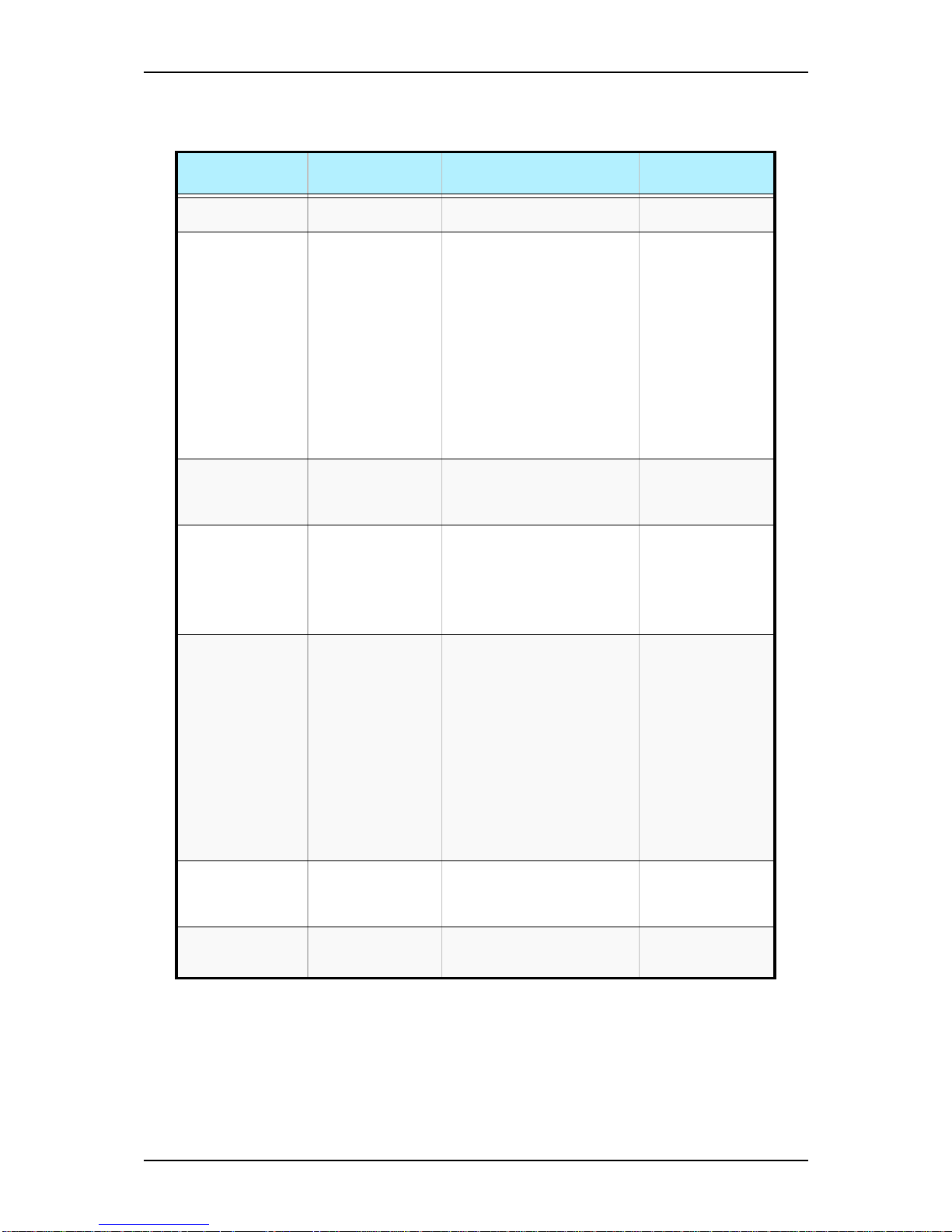
Table 3 - 4: Primary And Secondary Master And Slave IDE Submenus
Feature Choices or
Display Only
Description Your Setting
Type Auto
Not Installed
Select Auto if a device is
attached to the IDE channel.
LBA (Large Mode Disabled
Auto
LBA stands for "logical block
addressing". Instead of
referring to locations by passing
to the disk a cylinder, head and
sector number (CHS
addressing), the sectors are
serialized so that each just has
an integer number; 0, 1, 2, etc.
up to the total number of
sectors on the disk. Disabled
will disable the LBA mode, Auto
will enable it if the IDE device
supports it. This field is
informational only, for Type
Auto.
Block (Multi-Sector
Transfer)
Disabled
Auto
Enales or disables multiple
sector transfers support. This
field is informational only, for
Type Auto.
PI0 Mode Auto
0
1
2
3
4
Select the method for moving
data to/from the drive. This field
is informational only, for Type
Auto. This field is updated to
display only the modes
supported by the attached
device.
DMA Mode Auto
SWDMA0
SWDMA1
SWDMA2
MWDMA0
MWDMA1
MWDMA2
UDMA0
UDMA1
UDMA2
UDMA3
UDMA4
UDMA5
UDMA6
Selects the DMA mode used for
moving data to/from the drive.
This field is informative only for
Type Auto.
SMART Monitoring Auto
Disabled
Enabled
Enables or disables the Self
Monitoring, Analysis and
Reporting Technology
(S.M.A.R.T.)
32Bit Data Transfer Disabled
Enabled
This option allows you to
enable or disable 32 bit IDE
transfers.
Page 56
NS170 User Guide - Configuring Your Server
3 - 14
Notes:
1. This motherboard supports Intel Pentium 4 CPUs with
Hyper-Threading Technology
2. Hyper-Threading Technology is supported under Windows
2003, Windows XP and Linux 2.4x (kernel) and later
versions only. Under Linux, use the Hyper-Threading
compiler to compile code. If you are using any other
operating system, disable the Hyper-Threading Technology
in this submenu to ensure server stability and performance.
3. It is recommended that you install Windows XP Service
Pack 1.
4. Make sure to enable the Hyper-Threading Technology in
BIOS before installing a supported operating system.
5. For more information on Hyper-Threading Technology, visit
www.intel.com/info/hyperthreading.
Note: The BIOS may display more options that presented
here.
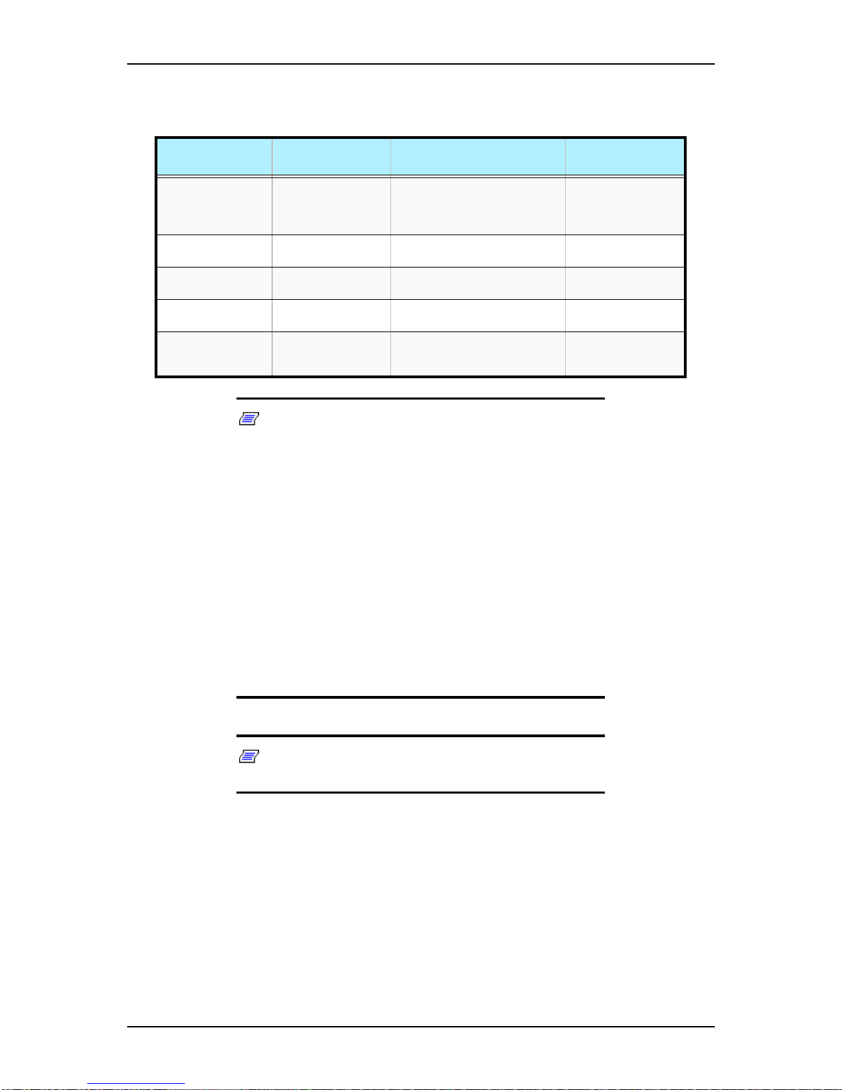
Table 3 - 5: Processor Settings Submenu
Feature Choices or
Display Only
Description Your Setting
Processor Retest Yes
No
If Yes is selected, the BIOS will
clear historical processor status
and retest the processor on
next boot.
Processor Speed Display only Displays the processor speed
detected by the BIOS
Processor 1 CPUID Display only Displays the processor CPU ID
detected by the BIOS
Processor 1 L2
Cache
Display only Displays the processor level 2
cache detected by the BIOS
Hyper-Threading
Technology
Enabled
Disabled
Enables or disables the HyperThreading technology.
See note below.
Page 57
NS170 User Guide - Configuring Your Server
3 - 15
Advanced Menu and Submenus
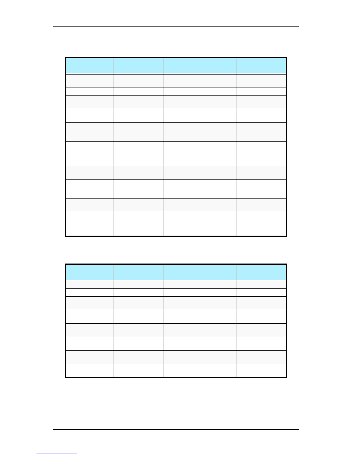
Table 3 - 6: Advanced Menu
Feature Choices or
Display Only
Description Your Setting
Memory
Configuration
Select submenu
PCI Configuration Select submenu
Peripheral
Configuration
Select submenu
Advanced Chipset
Control
Select submenu
Boot-time
Diagnostic Screen
Disabled
Enabled
Enables or disables the display
of the diagnostic screen during
boot.
Reset Configuration
Data
No
Yes
Select Yes if you want to clear
the Extended System
Configuration Data (ESCD)
area.
NumLock On
Off
Selects power on state for
NumLock.
Memory/Processor
Error
Boot
Halt
If Boot is selected, the system
will attempt to boot after a
memory or processor error.
SATA RAID Enable Disabled
Enabled
Enables or disables the SATA
RAID function.
Multiprocessor
Specification
1.1
1.4
Configures the MP specification
revision level. Some operating
systems will require 1.1 for
compatibility reasons.
Table 3 - 7: Memory Configuration Submenu
Feature Choices or
Display Only
Description Your Setting
System Memory Display only e.g. 640 KB
Extended Memory Display only e.g. 784896 KB
DIMM Group #1
Status
Display only e.g. Normal
DIMM Group #2
Status
Display only e.g. Normal
DIMM Group #3
Status
Display only e.g. Not Installed
DIMM Group #4
Status
Display only e.g. Not Installed
Memory Retest No
Yes
Clears the memory error status
Extended RAM Step 1MB
Disabled
Test the extended memory
once per MB or no test.
Page 58
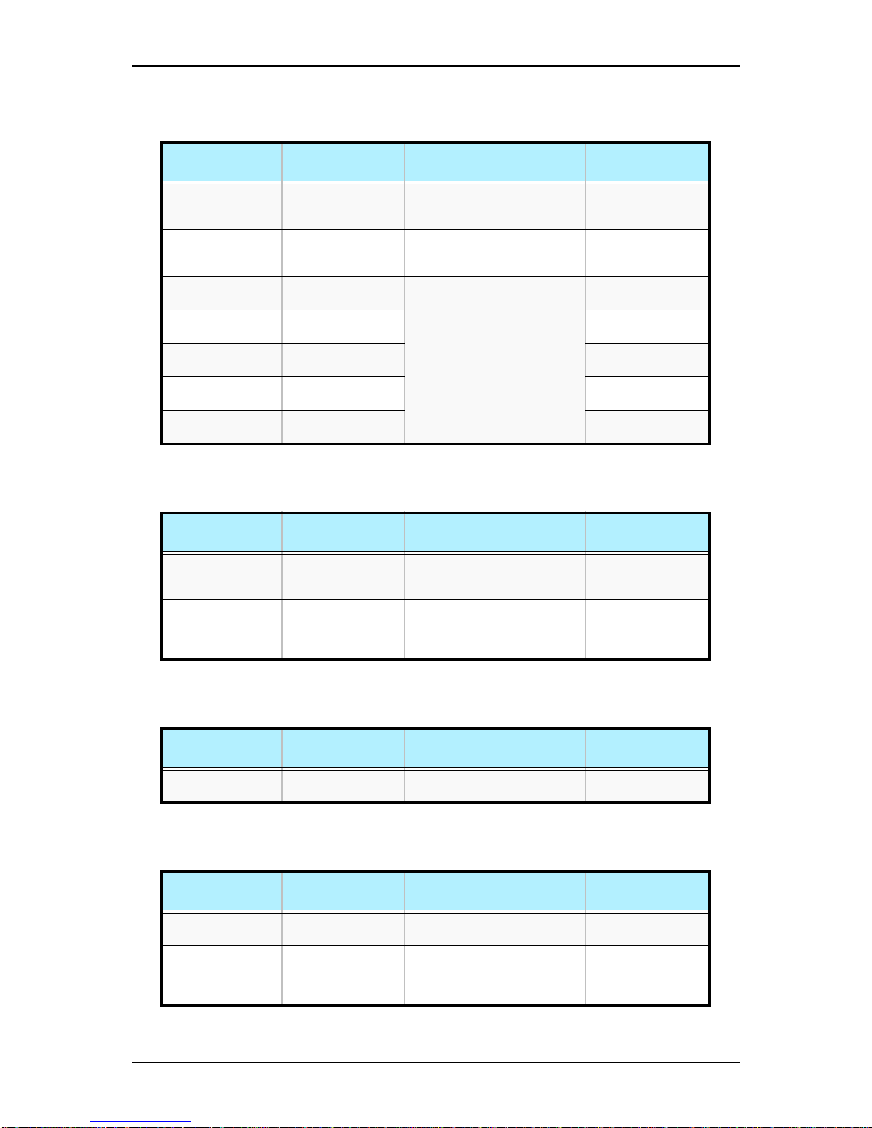
NS170 User Guide - Configuring Your Server
3 - 16
Table 3 - 8: PCI Configuration Submenu
Feature Choices or
Display Only
Description Your Setting
PCI Device,
Embedded device
#1
Select submenu
PCI Device,
Embedded device
#2
Select submenu
PCI Slot 1 Option
ROM
Disabled
Enabled
Initialises device expansion
ROM; Set it to disable if the
board is not implied in the boot
process.
PCI Slot 1 Option
ROM
Disabled
Enabled
PCI Slot 1 Option
ROM
Disabled
Enabled
PCI Slot 1 Option
ROM
Disabled
Enabled
PCI Slot 1 Option
ROM
Disabled
Enabled
Table 3 - 9: PCI Device, Embedded device #1 Submenu
Feature Choices or
Display Only
Description Your Setting
Onboard CSA LAN
Control
Disabled
Enabled
This option allows you to
enable or disable the onboard
CSA LAN controller
Option ROM Scan Disabled
Enabled
Initialises device expansion
ROM.
Only if Onboard CSA LAN
Control is enabled.
Table 3 - 10: PCI Device, Embedded device #2 Submenu
Feature Choices or
Display Only
Description Your Setting
Onboard VGA
Control
Disabled
Enabled
Enables or disables the
onboard VGA controller.
Table 3 - 11: Peripheral Configuration Submenu
Feature Choices or
Display Only
Description Your Setting
Serial Port A Disabled
Enabled
Enables or disables the serial
port A
Base I/O address 3F8
2F8
3E8
2E8
Set the base I/O address for
serial port A
Page 59
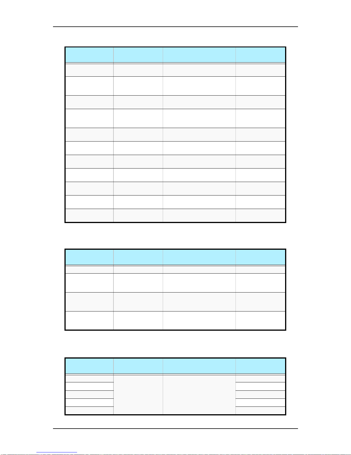
NS170 User Guide - Configuring Your Server
3 - 17
Interrupt IRQ3
IRQ4
Set the interrupt for serial port A
Serial port B Disabled
Enabled
Only if serial port B present,
grayed otherwise.
Same as serial port A
Parallel port Disabled
Enabled
Enables or disables the parallel
Port.
Mode Bi-directional
EPP
ECP
Set the mode for the parallel
port.
Base I/O adress 378
278
Set the base I/O address for the
parallel port.
Interrupt IRQ 5
IRQ 7
Set the interrupt for the parallel
port.
DMA channel DMA 1
DMA 3
Set the DMA channel for the
parallel port
PS/2 Mouse Disabled
Enabled
Enables or disables the PS/2
mouse.
USB Controller Disabled
Enabled
Enables or disables the USB
controller
Legacy USB
Support
Disabled
Enabled
Enables or disables support for
legacy USB.
Serial ATA Disabled
Enabled
Enables or disables Serial ATA.
Table 3 - 12: Advanced Chipset Control Submenu
Feature Choices or
Display Only
Description Your Setting
PCI Device Select submenu
Wake On LAN/PME Disabled
Enabled
Enables or disables system
wake-up when a LAN or PME
wake-up event occurs.
Wake On Ring Disabled
Enabled
Enables or disables system
wake-up when the modem is
ringing.
Wake On RTC
Alarm
Disabled
Enabled
Enables or disables system
wake-up when a RTC Alarm
wake-up event occurs.
Table 3 - 13: PCI Device Submenu
Feature Choices or
Display Only
Description Your Setting
PCI IRQ line 1 Disabled
Auto Select
IRQ 3, 4, 5, 6, 7, 9,
10, 11, 12, 14, 15
A PCI device cannot use IRQs
already in use by ISA or EISA
devices. Use Auto Select only if
no ISA or EISA legacy cards
are installed.
PCI IRQ line 2
PCI IRQ line 3
PCI IRQ line 4
PCI IRQ line 5
Table 3 - 11: Peripheral Configuration Submenu (Continued)
Feature Choices or
Display Only
Description Your Setting
Page 60
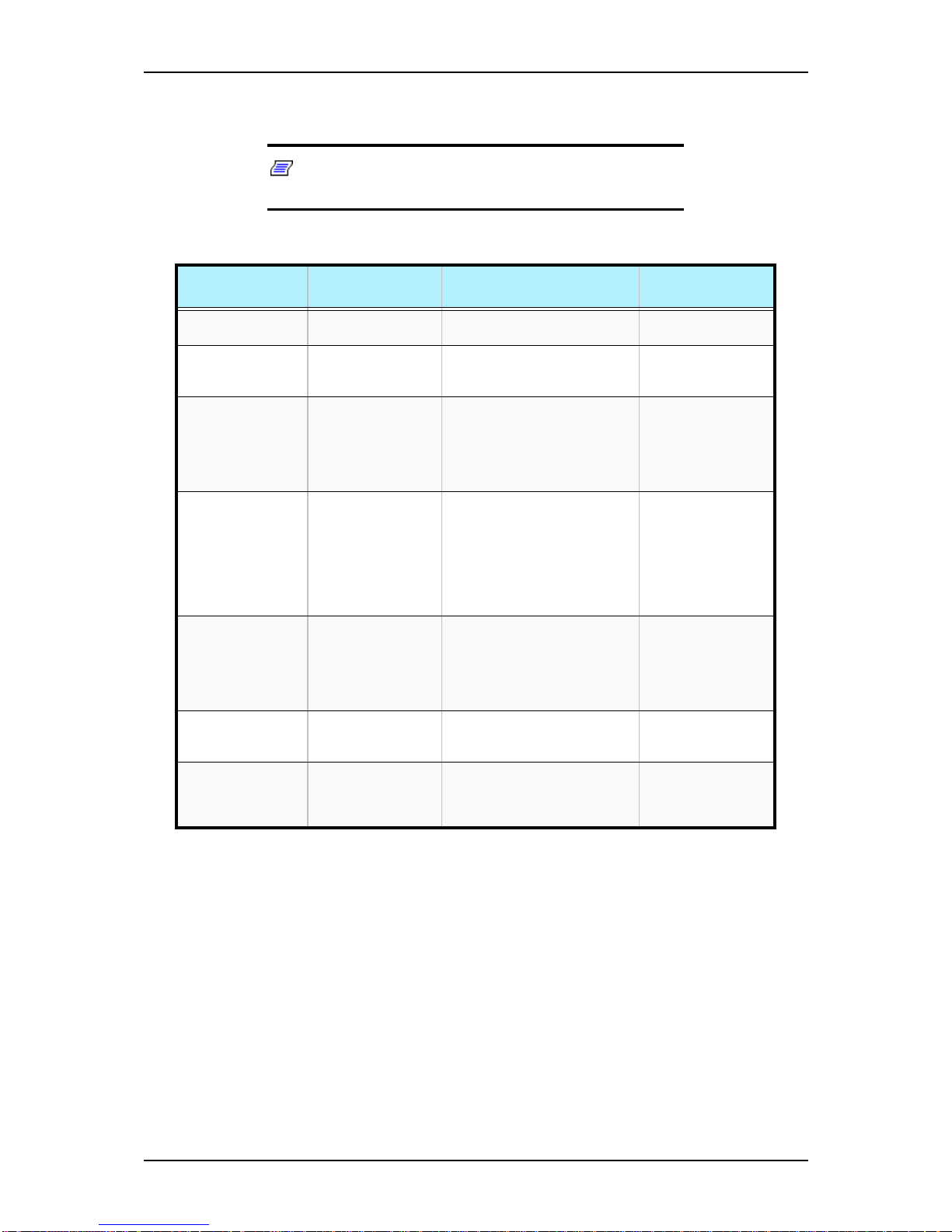
NS170 User Guide - Configuring Your Server
3 - 18
Security Menu
Note: Enabling the Supervisor Password field requires a
password for entering Setup. The passwords are not case sensitive.
Table 3 - 14: Security Menu
Feature Choices or
Display Only
Description Your Setting
User Password is Set
Clear
Indicates whether the user
password is set (view only).
Supervisor
Password is
Set
Clear
Indicates whether the
supervisor password is set
(display only).
Set User Password Up to 7
alphanumeric
characters
Press Enter to display the user
password entry screen. With a
user password, only certain
menus are accessible. This
option is available only if the
Supervisor Password is set.
Set Supervisor
Password
Up to 7
alphanumeric
characters
Press Enter to display the
supervisor password entry
screen. With the supervisor
password, all SETUP menus
are available for access. This
option is available only when
you log into the SETUP utility
with the supervisor password.
Password On Boot Disabled
Enabled
Specify whether to request a
password entry at boot-up.
Administrator password setup
is required.
Only available if supervisor
password is set.
Fixed Disk Boot
Sector
Normal
Write Protect
Allows to write protect hard disk
boot sector to protect against
viruses.
Floppy Write Protect User
Supervisor
Allows to control access to
diskette drives.
Only available if supervisor
password is set.
Page 61
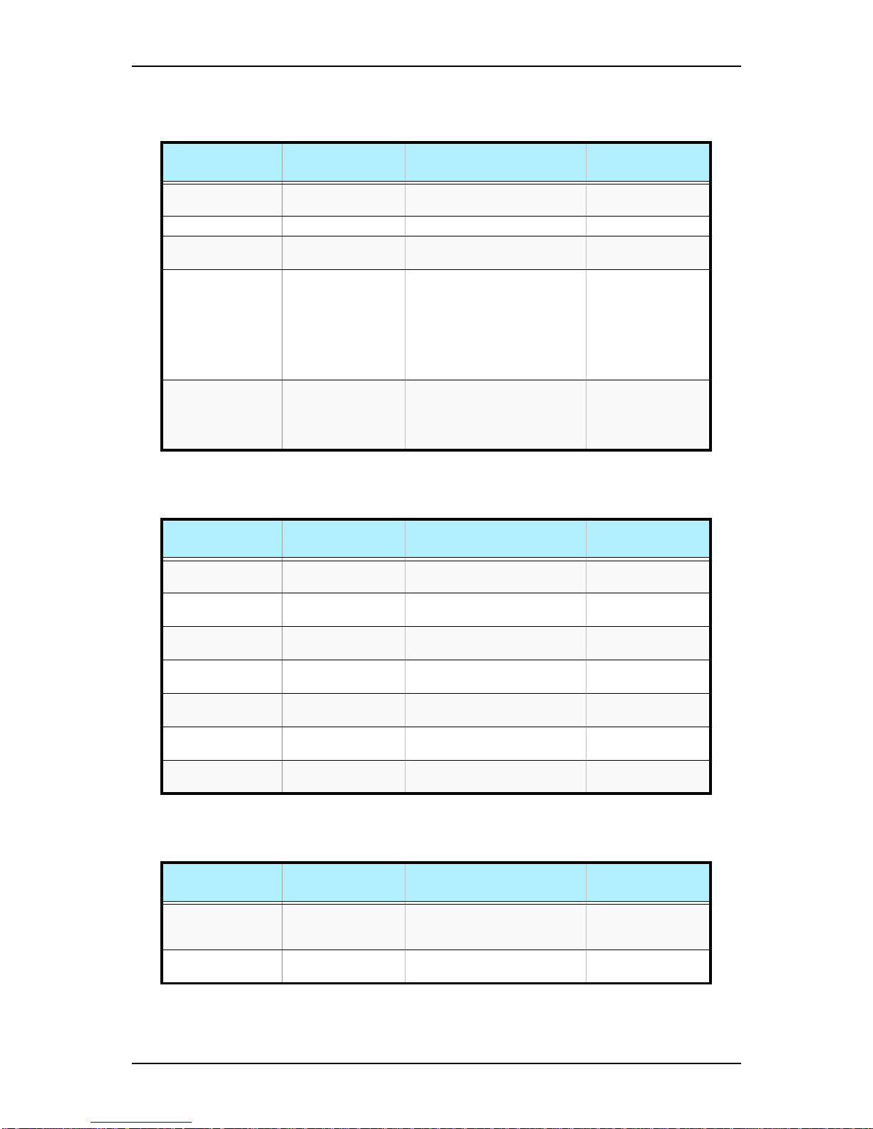
NS170 User Guide - Configuring Your Server
3 - 19
Server Menu and Submenus
Table 3 - 15: Server Menu
Feature Choices or
Display Only
Description Your Setting
System
Management
Select Submenu
Console Redirection Select Submenu
Assert NMI on
SERR
Disabled
Enabled
Sets support of PCI bus system
error (SERR).
POST Error Pause Disabled
Enabled
Specifies whether the system
waits for user intervention on
critical POST errors.
If no keyboard is connected to
the system, this option is
ignored and the system always
continues to bootup.
AC-LINK Stays Off
Last State
Power On
Sets the AC-LINK feature.
Determines the mode of
operation if a power loss
occurs.
Table 3 - 16: System Management Submenu
Feature Choices or
Display Only
Description Your Setting
BIOS Version e.g. 4N34 Indicates BIOS version number.
(View only)
Board Part Number e.g.856-123320-002 Indicates the part number of
mother board. (View only)
Board Serial
Number
_ Indicates the serial number of
mother board. (View only)
System Part
Number
e.g. [N8100-935] Indicates the system part
number. (View only)
System Serial
Number
e.g. KIR-000001 Indicates the serial number of
system. (View only)
Chassis Part
Number
e.g. 856-060350001
Indicates the part number of
chassis. (View only)
Chassis Serial
Number
e.g. 04 Indicates the serial number of
chassis. (View only)
Table 3 - 17: Console Redirection Submenu
Feature Choices or
Display Only
Description Your Setting
BIOS Redirection
Port
Disabled
Serial Port A
Specify the serial port to which
a hardware console is
connected.
ACPI Redirection
Port
Disabled
Serial Port A
Specify the serial port to which
an ACPI console is connected.
Page 62
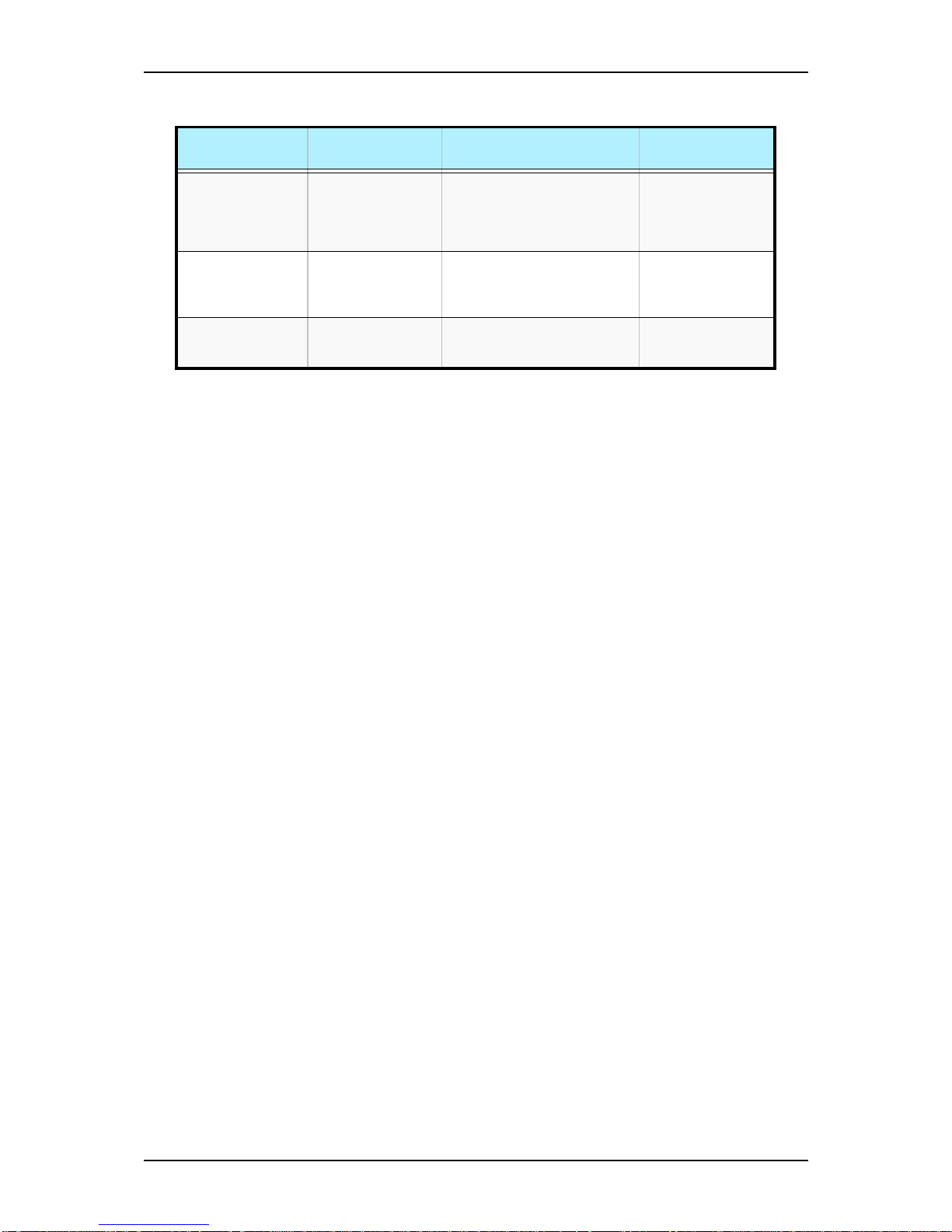
NS170 User Guide - Configuring Your Server
3 - 20
Baud Rate 9600
19.2K
38.4K
57.6K
115.2K
Selects a baud rate for
communications with the
connected HW console.
Flow Control None
XON/XOFF
CTS/RTS
CTS/RTS + CD
Select a flow control method.
Terminal Type PC ANSI
VT100+
VT-UTF8
Specify the type of remote
console.
Table 3 - 17: Console Redirection Submenu (Continued)
Feature Choices or
Display Only
Description Your Setting
Page 63
NS170 User Guide - Configuring Your Server
3 - 21
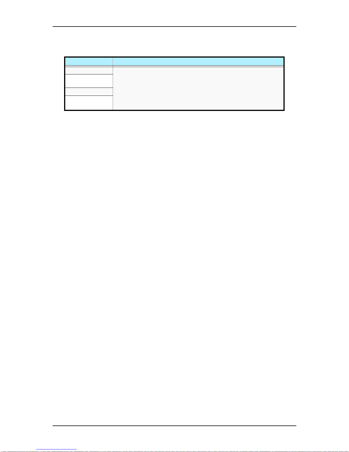
Boot Menu
Table 3 - 18: Boot Menu
Feature Description
CD-ROM Drive Keys used to view or configure devices:
<Enter> expand or collapses devices with a + or - in front
<Ctrl+Enter> expads all
>Shift+1> enables or disables a device
<+> and <-> moves the device up or down
<n> may move removable device beetween hard disks or removable disks
<d> removes a device that is not installed
+Removable
Devices
+ Hard Drive
IBA GE Slot 0208
v1216
Page 64
NS170 User Guide - Configuring Your Server
3 - 22
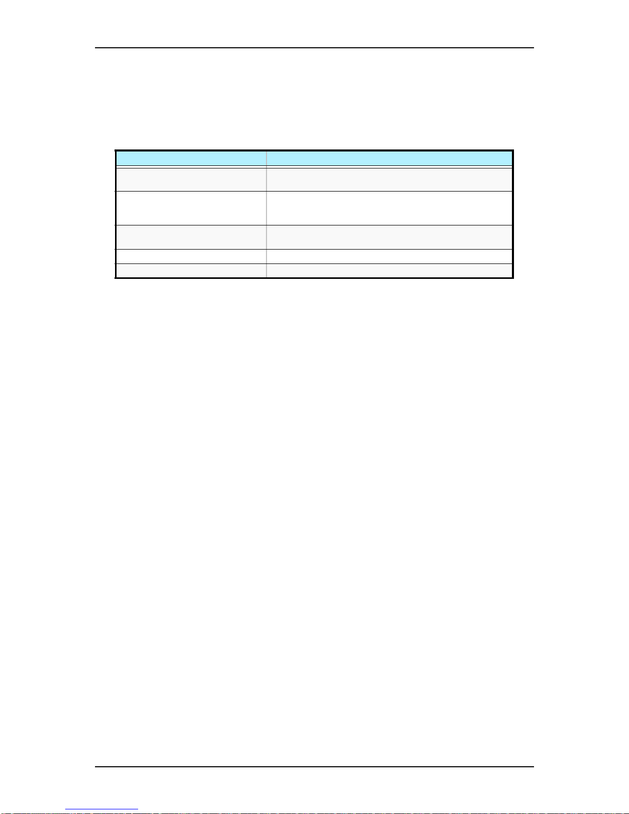
Exit Menu
You can make the following selections on the Exit Menu. Select an option using the up
or down arrow keys, then press <Enter> to execute the option. Pressing <Esc> does
not exit this menu. You must select one of the items from the menu or menu bar to exit.
Table 3 - 19: Exit Menu
Choices Description
Exit Saving Changes Exit after writing all modified Setup item values to NVRAM.
F10 key can be used for this operation.
Exit Discarding Changes Exit leaving NVRAM unmodified. User is prompted if any of
the setup fields were modified.
Esc key can be used for this operation.
Load Setup Defaults Load default values for all SETUP items.
F5 key can be used for this operation.
Discard Changes Read previous values of all Setup items from NVRAM.
Save Changes Save changes to NVRAM without exiting the Setup.
Page 65
NS170 User Guide - Configuring Your Server
3 - 23
SCSISelect Utility
The SCSISelect Utility detects and configures the SCSI controller located on the
system board or an optional SCSI controller board installed in your system. This utility
may be started with a simple key operation while POST is in progress and requires no
specific start-up disk.
The SCSISelect Utility is used mainly to set the transfer rate of connected SCSI device.
Use the SCSISelect Utility to:
■ Change default values
■ Check and/or change SCSI device settings that may conflict with those of other
devices in the server.
Running the SCSISelect Utility
You access the SCSISelect Utility when you turn on or reboot your system.
To run the utility, perform the following procedure:
1. Power-on or reboot the system.
2. When this message appears on the video monitor:
Press Ctrl-A to run SCSI Utility...
3. Press Ctrl+A to run this utility. The SCSI utility starts. When the Adaptec
SCSI Utility detects more than one 29320ALP host adapter, it displays a
selection menu listing the slot number of each adapter. When the selection
menu appears, select the adapter you wish to configure as follows:
29320ALP at slot 01 03:01:00
4. Once you select the adapter, the following screen is displayed:
5. If you wish to format a disk, verify disk media, or display a list of devices and
their SCSI IDs, select “SCSI Disk Utilities”. If you wish to configure the
adapter or a device, select “Configure/View Controller Settings”.
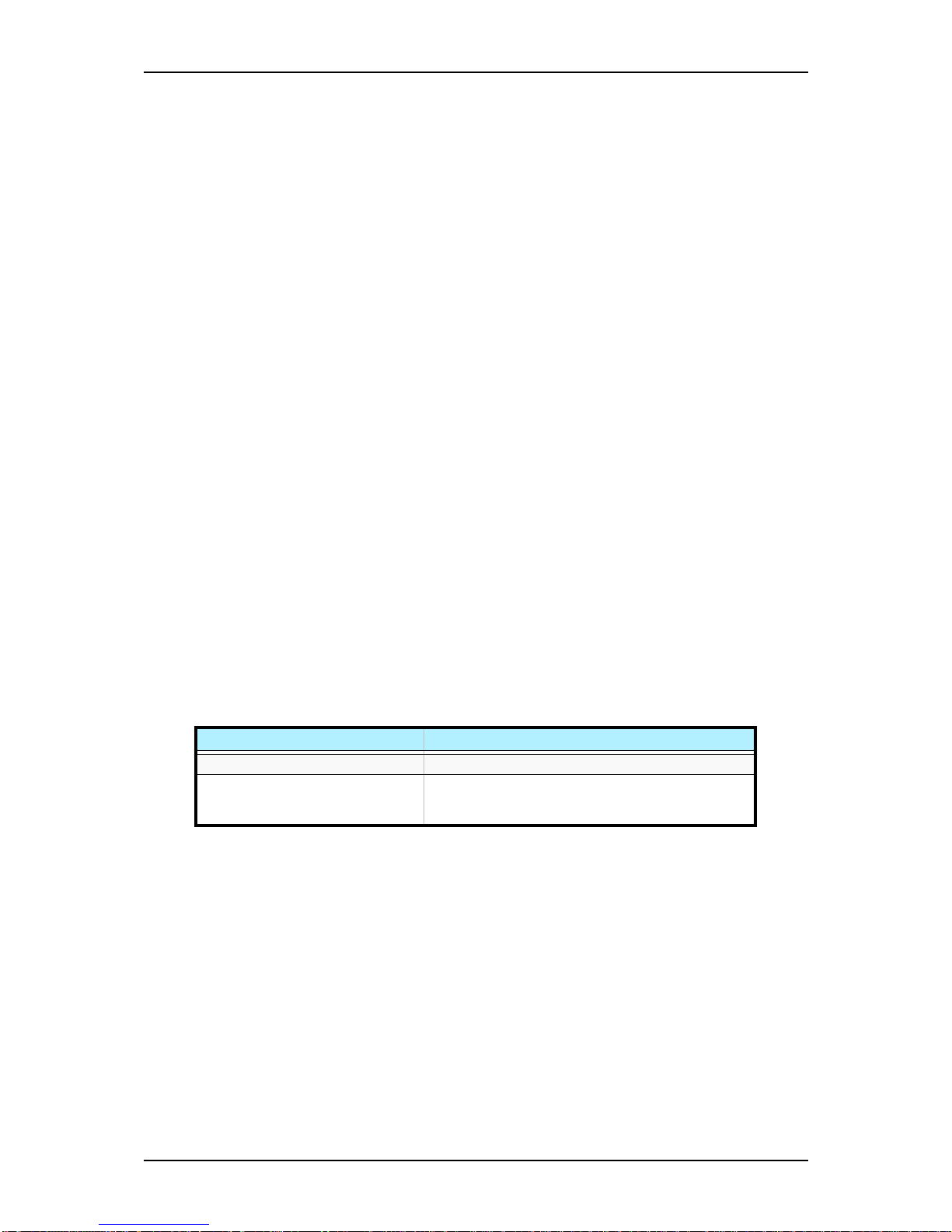
Table 3 - 20: SCSISelect Utility Selection Menu
Menu Description
Configure/View Controller Settings Configure host adapter and device settings.
SCSI Disk Utilities The utility scans the SCSI bus for SCSI devices,
reports a description of each device. Run these utilities
before configuring SCSI devices.
Page 66
NS170 User Guide - Configuring Your Server
3 - 24
Adaptec SCSI Utility Configuration Settings
The following keys are active for all Adaptec SCSI Utility screens:
The following table shows the normal settings for the Adaptec SCSI Utility and
provides a place for you to record any changes you make to these settings.
Table 3 - 21: Active Keys
Key Action
Arrows Up and down arrows move from one parameter to another within a
screen.
ENTER Displays options for a configurable parameter. Selects an option.
ESC Moves back to previous screen or parameter or EXIT if at the Main
menu.
F5 Switches between color and monochrome.
F6 Resets to host adapter defaults.
Table 3 - 22: SCSISelect Utility Setup Configurations
OPTION RECOMMENDED SETTING OR
DISPLAY ONLY
YOUR
CONFIGURATION
SCSI Bus Interface Definitions
SCSI Controller ID 7
SCSI Controller Parity Enabled
SCSI Controller Termination Enabled
Additional Options
Boot Device Configuration Press ENTER for menu
Master SCSI Controller 29320ALP slot 01 03:01:00
Boot SCSI Controller 29320ALP slot 01 03:01:00
SCSI Device Configuration Press ENTER for menu
Sync Transfer Rate (MB/Sec) 320
Packetized Ye s
QAS Yes
Initiate Wide Negotiation Yes
Enable Disconnection Yes
Send Start Unit Command Yes
BIOS Multiple LUN Support
No
1
Include in BIOS Scan
Yes
1
Advanced Configuration Press ENTER for menu.
Reset SCSI Bus at IC
Initialization
Enabled
Display <Ctrl-A> Messages
During BIOS Initialization
Enabled
Extended Int13 Translation for
DOS
Drives >1 GByte
Enabled
POST Display Mode Verbose
SCSI Controller Int13 Support
Enabled
1
Domain Validation
Enabled
1
Page 67
NS170 User Guide - Configuring Your Server
3 - 25
1
No effect if BIOS is disabled.
2
Do not remove media from a removable media drive if it is under BIOS control.
SCSI Disk Utilities
This utility scans the SCSI bus for SCSI devices, reports a description of each device.
Run these utilities before configuring SCSI devices.
To enter the utility, select "SCSI Disk Utilities" on the Options menu.
The SCSI ID scan begins displaying the message as shown below.
When the SCSI ID scan completes, the screen listing SCSI IDs and associated devices
appears.
With this screen you can determine the SCSI IDs for installed options. You can also
view the device information by selecting a device and pressing Enter.
Support Removable Disks
Under Int13 as Fixed Disks
Disabled
1, 2
BIOS Support for Bootable
CDROM
Enabled
1
Table 3 - 22: SCSISelect Utility Setup Configurations (Continued)
OPTION RECOMMENDED SETTING OR
DISPLAY ONLY
YOUR
CONFIGURATION
Scanning SCSI ID : 0 LUN Number : 0
Select SCSI Disk and press <Enter>
SCSI ID #0 : No device
SCSI ID #1 : No device
SCSI ID #2 : No device
SCSI ID #3 : No device
SCSI ID #4 : No device
SCSI ID #5 : No device
SCSI ID #6 : No device
SCSI ID #7 : Adaptec AIC-7901
SCSI ID #8 : No device
SCSI ID #9 : No device
SCSI ID #10 : No device
SCSI ID #11 : No device
SCSI ID #12 : No device
SCSI ID #13 : No device
SCSI ID #14 : No device
SCSI ID #15 : No device
Adaptec 29320ALP
Page 68
NS170 User Guide - Configuring Your Server
3 - 26
The following submenu is displayed.
The following table lists submenu items and descriptions.:
Exiting Adaptec SCSI Utility
To exit the Adaptec SCSI Utility, press ESC until a message prompts you to exit (if you
changed any settings, you are prompted to save the changes before you exit).
SCSI ID#4: xxxxxxxxx
Firmware: xxxx xxx
Capacity: xxGB
Format
Verify Disk Media
Table 3 - 23: Submenu Items
Submenu item Description
Format Formats the selected device.
Verify Disk Media Verifies all the sectors in the selected device. If one or more bad
sectors are found, the sectors are remapped.
Page 69
NS170 User Guide - Configuring Your Server
3 - 27
RAID Configuration Utility
Your server includes the serial ATA RAID controller by supporting the RAID levels 0
and 1. The Array Configuration Utility (ACU) that is an embedded BIOS utility is used
to create, configure, and manage arrays.
Note: To configure the RAID drive with more than two SATA hard disk drives, purchase the optional RAID controller
board and hard disk drives.
Installing the Hard Disk Drives
Install the two serial ATA hard disk drives to your server. Refer to Chapter 4 for details
Caution
Use identical hard disk drives.
Activating the SATA RAID Feature
To run the Array Configuration Utility (ACU), run the BIOS setup utility and change
the "SATA RAID Enable" option in the "Advanced" menu to "Enable". Refer to
"System BIOS (BIOS SETUP Utility)" described earlier in this chapter for detail.
Page 70
NS170 User Guide - Configuring Your Server
3 - 28
Running the Array Configuration Utility (ACU)
To run ARCU, press Ctrl+A when prompted by the following message during the
system startup:
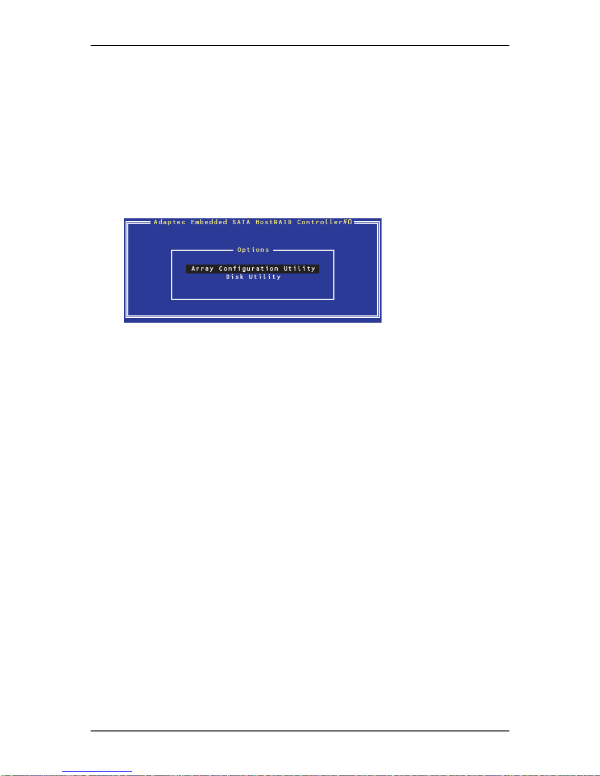
Press <Ctrl><A> for Adaptec RAID Configuration Utility
The ARCU menu appears, presenting these options:
■ Array Configuration Utility (ACU)
■ Disk Utilities
To select an option from this menu, browse with the arrow keys and then press Enter.
In some cases, selecting an option displays another menu. To return to the previous
menu at any time, press Esc.
Page 71
NS170 User Guide - Configuring Your Server
3 - 29
Using the Array Configuration Utility
The Array Configuration Utility (ACU) enables you to create, manage, and delete
arrays from the controller’s BIOS, and initialize drives.
Managing Arrays
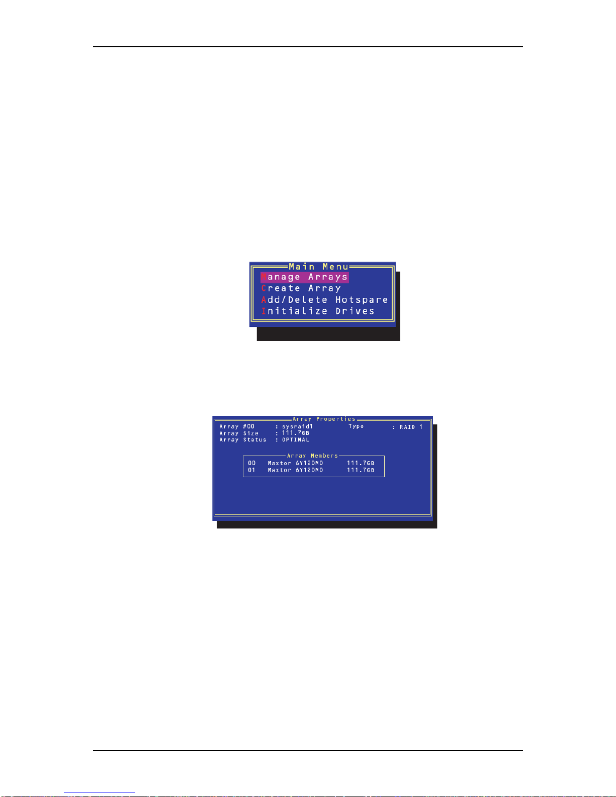
Use the Manage Arrays option to view array properties and members, and delete
arrays. The following sections describe these operations in greater detail.
Viewing Array Properties
To view the properties of an existing array:
1. At the BIOS prompt, press Ctrl + A.
2. From the ACU menu, select Manage Arrays.
3. From the List of Arrays dialog box, select the array you want to view and press
Enter.
The Array Properties dialog box appears, showing detailed information on the
array. The physical disks associated with the array are displayed here.
4. Press Esc to return to the previous menu.
Page 72
NS170 User Guide - Configuring Your Server
3 - 30
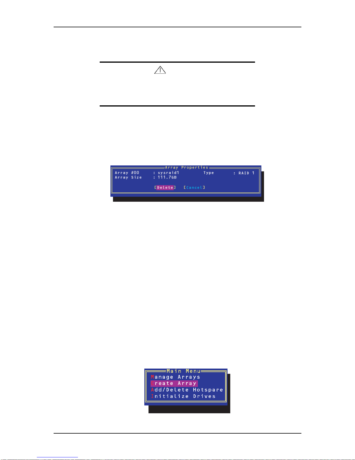
Deleting Arrays
Caution
Back up the data on an array before you delete it. Otherwise, all
data on the array is lost.
Deleted arrays cannot be restored.
To delete an existing array:
1. Turn on your server and press Ctrl + A when prompted to access the ARCU.
2. From the ACU menu, Array Configuration Utility.
3. From the main menu, select Manage Arrays.
Select the array you wish to delete and press Delete.
4. In the Array Properties dialog box, select Delete and press Enter.
The following prompt is displayed:
“Warning!! Deleting the array will render array unusable. Do you want to
delete the array?(Yes/No):”
RAID 1 only, the following prompt is also displayed:
“Deleting the partition will result in data loss! Do you also want to delete the
partition? (Yes/No):”
5. Press Y to delete the array or partition or N to return to the previous menu.
6. Press Esc to return to the previous menu.
Creating Arrays
Before creating arrays, make sure the disks for the array are connected and installed in
your system. Note that disks with no usable space, or disks that are uninitialized are
shown in gray and cannot be used. See Initializing Disk Drives described later.
To create an array:
1. Turn on your server and press Ctrl + A when prompted to access the ACU.
2. From the main menu, select Create Array.
Page 73
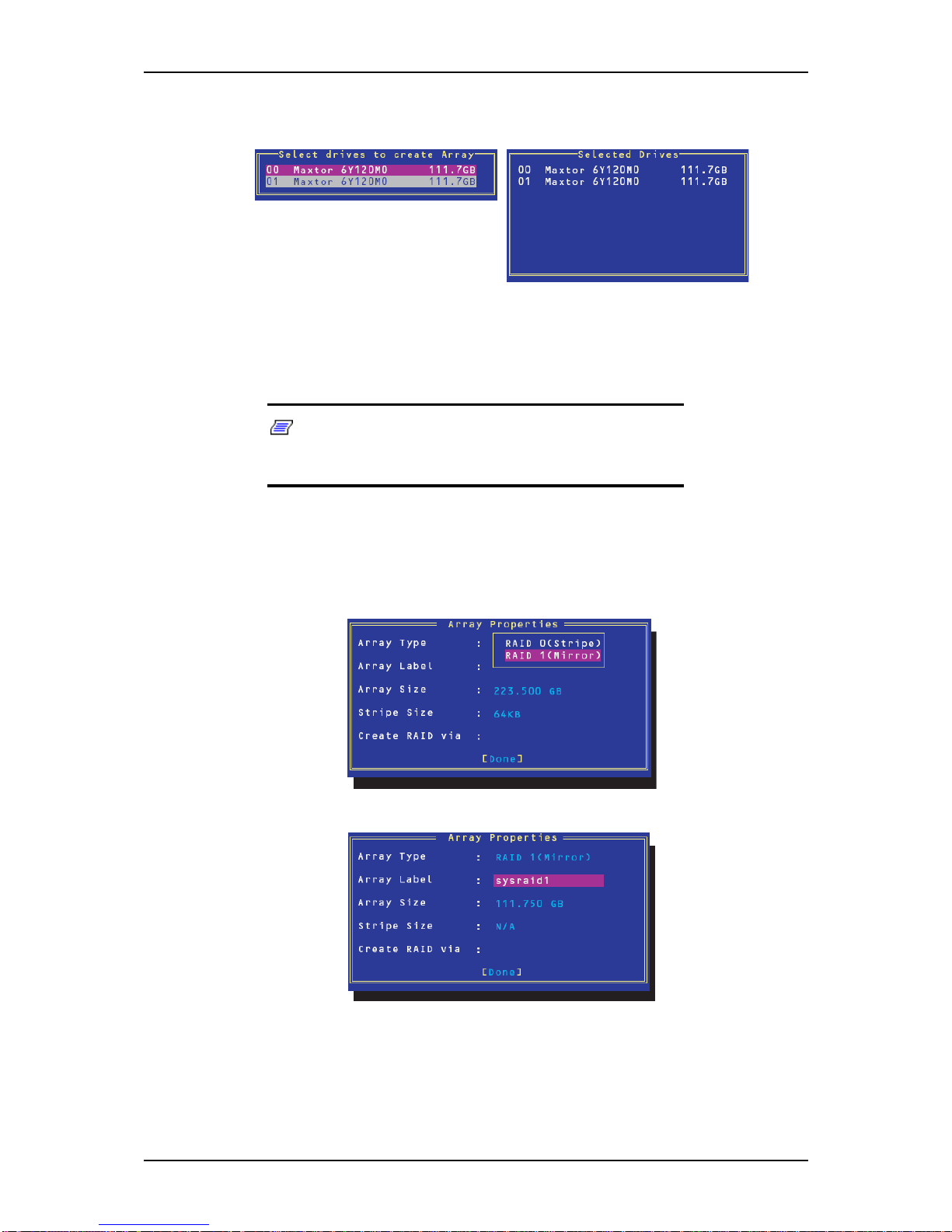
NS170 User Guide - Configuring Your Server
3 - 31
3. Select the disks for the new array and press Insert. To deselect any disk,
highlight the disk and press Delete.
4. Press Enter when both disks for the new array are selected. The Array
Properties menu displays.
Assigning Array Properties
Note: Once the array is created and its properties are
assigned, you cannot change the array properties using the
ACU. Instead, use Adaptec Storage Manager - Browser Edition.
To assign properties to the new array:
1. In the Array Properties menu, select an array type and press Enter. Note that
only the available array types, RAID0 and RAID1, are displayed. Each of
these types requires two drives.
2. Type in an optional label for the array and press Enter.
Page 74
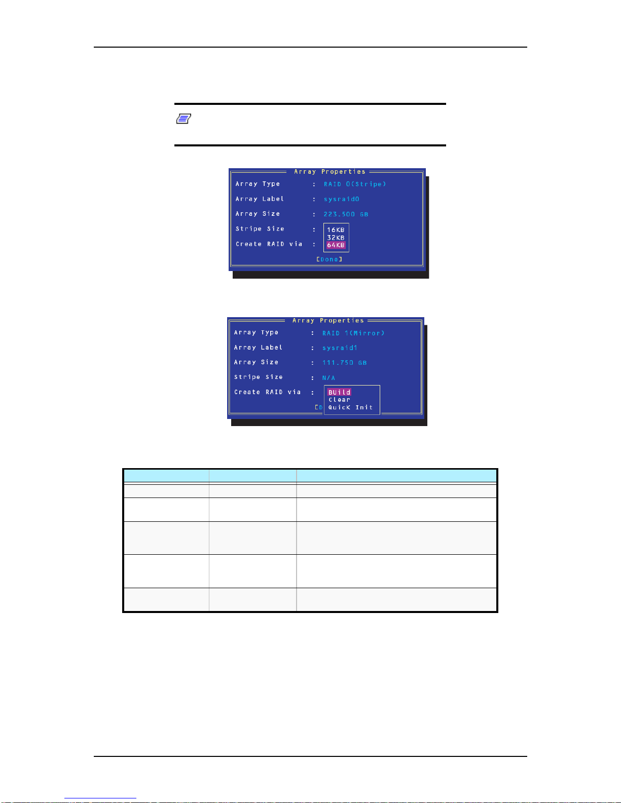
NS170 User Guide - Configuring Your Server
3 - 32
3. For RAID0, select the desired stripe size. Available stripe sizes are 16, 32, and
64 KB (default).
Note: NEC recommends that you do not change the
default.
4. Create RAID via allows you to select between the creation methods for RAID0
and RAID1. The following table gives examples of when each is appropriate.
Table 3 - 24: Using the Create RAID via property
RAID level Create via When appropriate
RAID0 No init Creating a RAID0 on new drives.
RAID0 Migrate Creating a RAID0 from on new drive and one drive
with data you wish to preserve.
RAID1 Build Any time you wish to create RAID1, but especially
if you have data on one drive that you wish to
preserve.
RAID Clear Creating a RAID1 on new drives, or when you
want to ensure that the array contains no data after
creation.
RAID1 Quick init Fastest way to create a RAID1. Appropriate when
using new drives.
Page 75
NS170 User Guide - Configuring Your Server
3 - 33
Caution
Do not interrupt the creation of a RAID 0 using the Migrate
option. Doing so would make the server unable to restart, and
there would be no way to recover the data that was on the
source drive.
Note:
■ Before adding a new drive to an array, back up any data
contained on the new drive. Otherwise, all data will be lost.
■ If you stop the Build or Clear process on a RAID1 from ACU,
you can only restart it from Adaptec Storage Manager Browser Edition.
■ RAID1 created using the Quick Init option may return some
data miscompares if you later run a consistency check. This
is normal and is not a cause for concern.
■ The ACU allows you to use drives of different sizes in a
RAID1. During a build operation however, only the smaller
drive can be selected as the source or first drive.
■ When migrating from single volume to RAID0, migrating
from a larger drive to a smaller drive is allowed. However the
destination drive must be at least half the capacity of the
source drive.
Caution
Adaptec does not recommend that you migrate or build an array
on Windows dynamic disks (volumes), as it will result in data
loss.
5. When you have finished, press Done.
Page 76
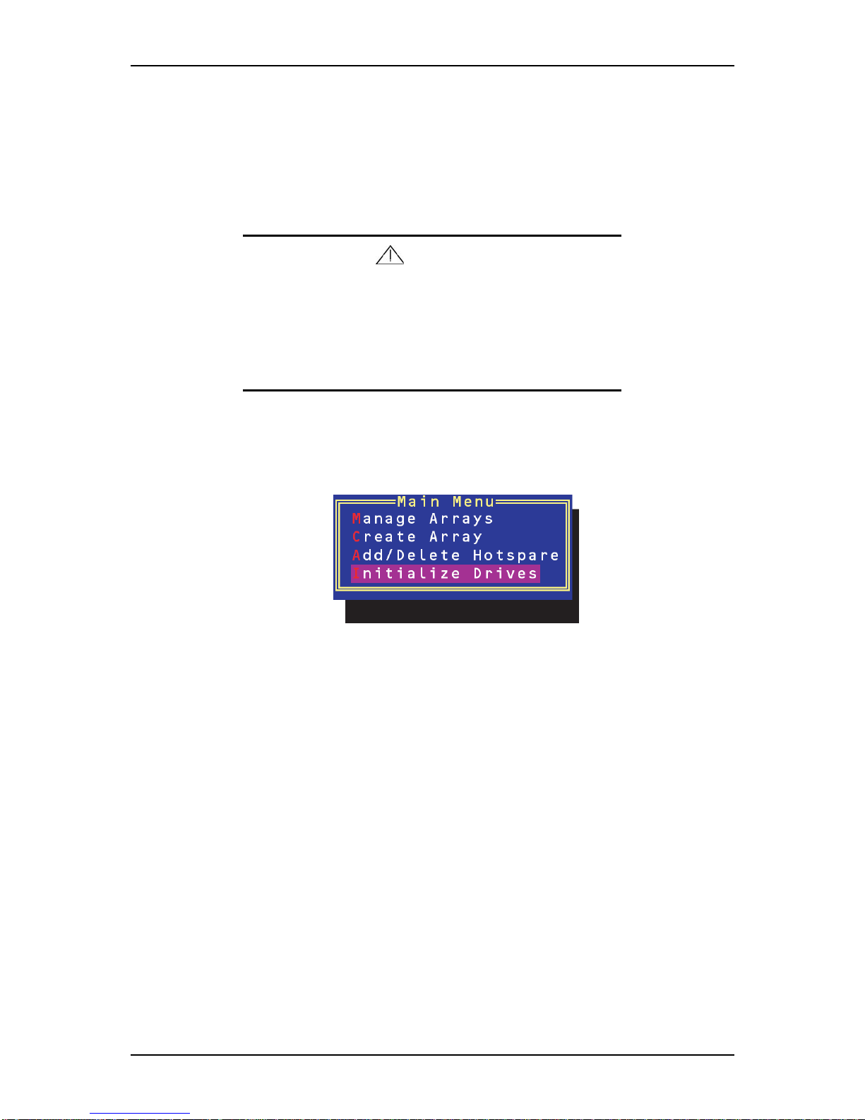
NS170 User Guide - Configuring Your Server
3 - 34
Initializing Disk Drives
If an installed disk does not appear in the disk selection list for creating a new array or
if it appears grayed out, you may have to initialize it before you can use it as part of an
array. Drives attached to the controller must be initialized before they can be used in an
array.
Caution
Initializing a disk overwrites the partition table on the disk and
makes any data on the disk inaccessible.
If the drive is used in an array, you may not be able to use the
array again. Do not initialize a disk that is part of a boot array. To
determine which disks are associated with a particular array,
see Viewing Array Properties described earlier in this section.
To initialize drives:
1. Turn on your server and press Ctrl + A when prompted to access the ACU.
2. Select Initialize Drives.
3. Use the up and down arrow keys to highlight the disk you wish to initialize and
press Insert.
4. Repeat Step 3 so that both drives to be initialized are selected.
5. Press Enter.
6. Read the warning message and ensure that you have selected the correct disk
drives to initialize. Type Y to continue.
Page 77
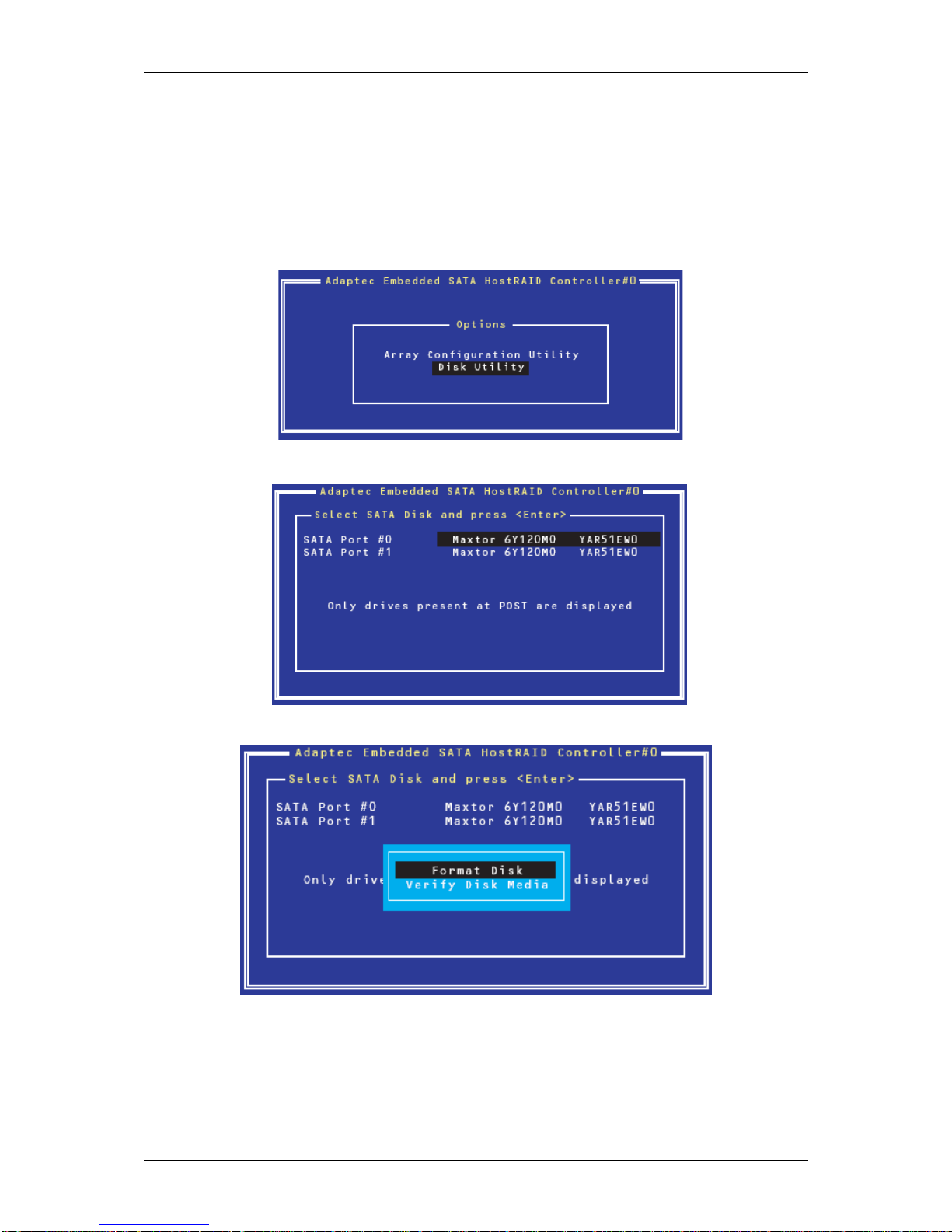
NS170 User Guide - Configuring Your Server
3 - 35
Using the Disk Utilities
The Disk Utilities enable you to format or verify the media of your Serial ATA hard
disks.
To access the disk utilities:
1. Turn on your server and press Ctrl + A when prompted to access the ACU.
2. From the ACU menu, select Disk Utilities.
3. Select the desired disk and press Enter.
You are offered the following options:
Page 78

NS170 User Guide - Configuring Your Server
3 - 36
■ Format Disk: Simulates a low-level format of the hard drive by writing zeros to
the entire disk. Serial ATA drives are low-level formatted at the factory and do not
need to be low-level formatted again.
Caution
Formatting destroys all data on the drive.
Be sure to back up your data before performing this operation.
■ Verify Disk Media—Scans the media of a disk drive for defects.
Page 79
NS170 User Guide - Configuring Your Server
3 - 37
Configuring MotherBoard Jumpers
Caution
■ Clearing the CMOS data resumes the factory-set configura-
tion data.
■ Do not change any other switch settings. Any change may
cause the server to fail or malfunction.
Warning
Never attempt to disassemble, repair, or alter the server on any
occasion other than described in this manual. Failure to follow
this instruction may cause an electric shock or fire as well as
malfunctions of the server.
To clear the CMOS data in the server:
1. Power off the server and disconnect the power cord and all the cables
connected on the rear of the server.
2. Remove the right side door (See “Removing or Installing the Right Side Door”
on page 4).
3. Remove the jumper from position 2 - 3 on jumper block.
Page 80
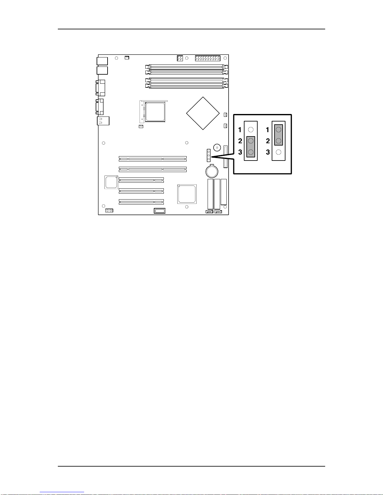
NS170 User Guide - Configuring Your Server
3 - 38
4. Install the jumper on position 1 - 2 (CMOS clear) of the jumper block.
A = Hold
B = Clear
Figure 3 - 2 : Configuring Motherboard Jumper
5. After three seconds, reinstall the jumper.
6. Reinstall the server and then turn on the power.
7. Press F2 when prompted to run the BIOS Setup utility, and select "Load Setup
Default" in the Exit menu.
A B
Page 81

4
Upgrading Your Server
■ General Information
■ Static Precautions
■ Equipment Log
■ Tools Recommended for Upgrading Your Server
■ Preparing Your Server for Upgrade
■ Removing or Installing the Right Side Door
■ Removing and Replacing the Front Panel
■ File Device
■ Expansion File Device Bay
■ Installing or Removing 3.5-inch Hard Disk Drives
■ Installing or Removing Random Access Memory
■ Installing and Removing a PCI Board
■ Replacing the Battery
■ Cabling the Devices
■ Preparing the Devices
■ Internal Cabling
Page 82
NS170 User Guide - Upgrading Your Server
4 - 2
General Information
Warning
■ The DC push-button on/off switch on the front panel does
not turn off completely the system AC power. Also, +5vdc is
present on the system boardwhenever the AC power cord is
connected between the system and an AC outlet. Before
doing the procedures in this manual, make sure that your
system is powered off and unplug the AC power cord from
the back of the chassis. Failure to disconnect power before
opening your system can result in personal injury and equipment damage.
■ Avoid burns: If the system has been running, any installed
processor and heat sink on the processor board(s) will be
hot. To avoid the possibility of a burn, be careful when
removing or installing components that are located near processors.
Caution
Operating your system with the side access panels removed
can damage your system components. For proper cooling and
airflow, always replace the side access panels before powering
on your system.
Contact your sales representative or dealer for a list of approved optional peripheral
devices.
Static Precautions
An electrostatic discharge (ESD) can damage disk drives, option boards, and other
components. You can provide some ESD protection by wearing an antistatic wrist strap
attached to chassis ground when handling system components.
Electronic devices can be easily damaged by static electricity. To prevent damage, keep
them in their protective packaging when they are not installed in your system.
Page 83

NS170 User Guide - Upgrading Your Server
4 - 3
Equipment Log
Use the equipment log form located at the end of this manual to record the model and
serial number of your system, all installed options, and any other pertinent information
specific to your system. You will need this information when configuring your system.
Tools Recommended
for Upgrading Your Server
Depending on the upgrade, you will need one or more of the following tools:
■ Phillips screwdriver (#1 bit and #2 bit)
■ Flat-head screwdriver
■ Small needle nose pliers
■ Pen or pencil
■ ESD workstation or antistatic wrist strap (recommended)
Preparing Your Server for Upgrade
To prepare your system for installation or removal of system components:
1. Observe the safety and ESD precautions listed under General Information and
Static Precautions at the beginning of this chapter.
2. Shutdown the operating system (OS).
3. If necessary, press the power on/off switch on the front panel of the server (see
See “Powering On Your Server” on page 8). The power-on LED goes out.
4. Power off the peripheral devices.
5. Unplug the system power cord(s) from the AC wall outlet(s).
Note: If the system power cord is connected to a power
control unit such as an UPS (Uninterruptible Power Supply),
refer to the UPS user's guide for proper power-off procedures.
6. Unplug all the I/O cables connected to the rear panel of your server.
Page 84
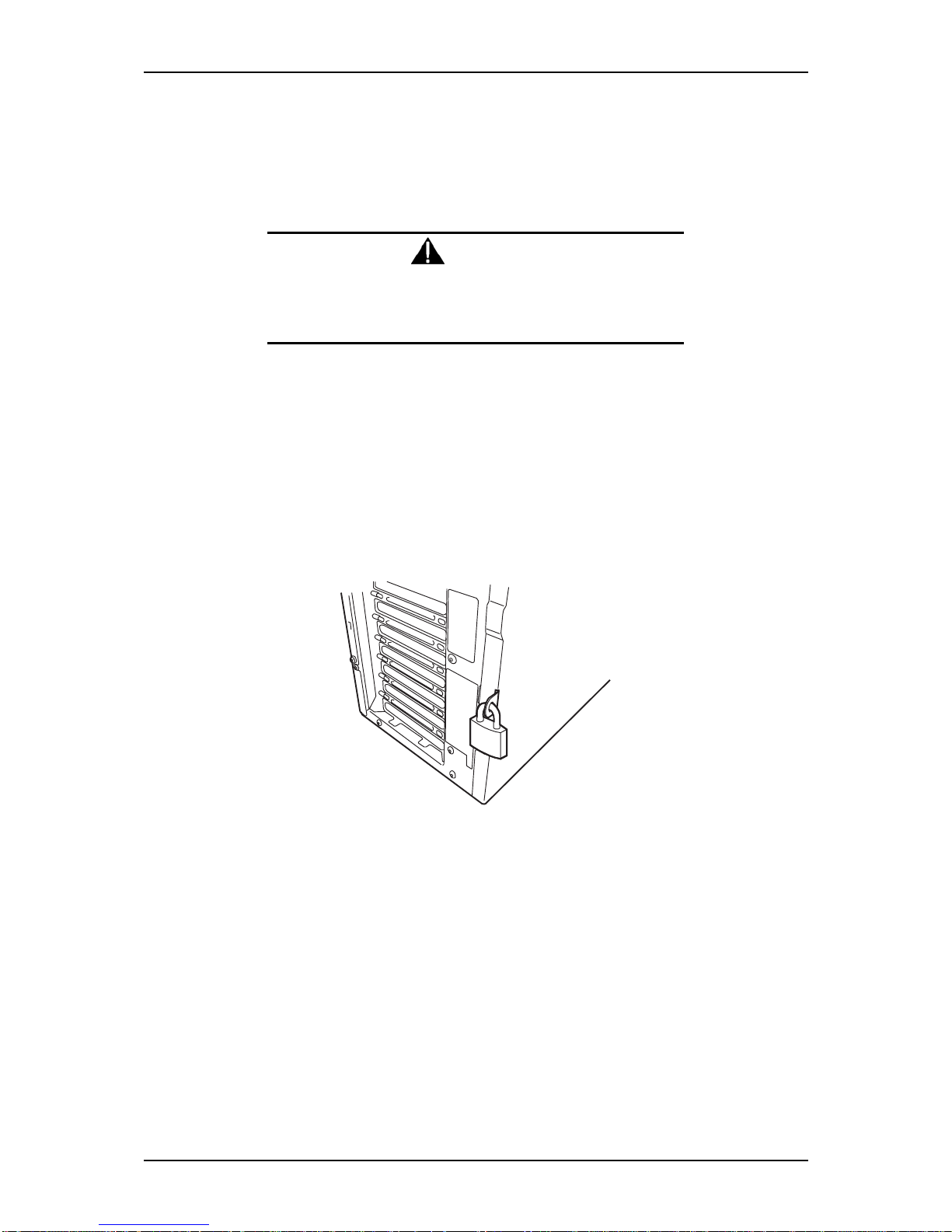
NS170 User Guide - Upgrading Your Server
4 - 4
Removing or Installing the Right Side Door
The right side door, also known as side cover, provides access to the disk drive bays, to
the motherboard and to the 5.25 and 3.5-inch bays.
Warning
Disconnect the power plug before working with the server.
Failure to do so may result in death or serious personal injury.
Removing the Right Side Door
1. Make sure the power switches for the computer, video monitor and any
peripheral devices are turned OFF and unplug the power cord (see the 'Safety
Precautions' chapter).
2. Disconnect the monitor and peripheral devices (printers, for instance) from the
system.
3. Unlock the right side door.
Figure 4 - 1 : Unlocking the Right Side Door
Page 85
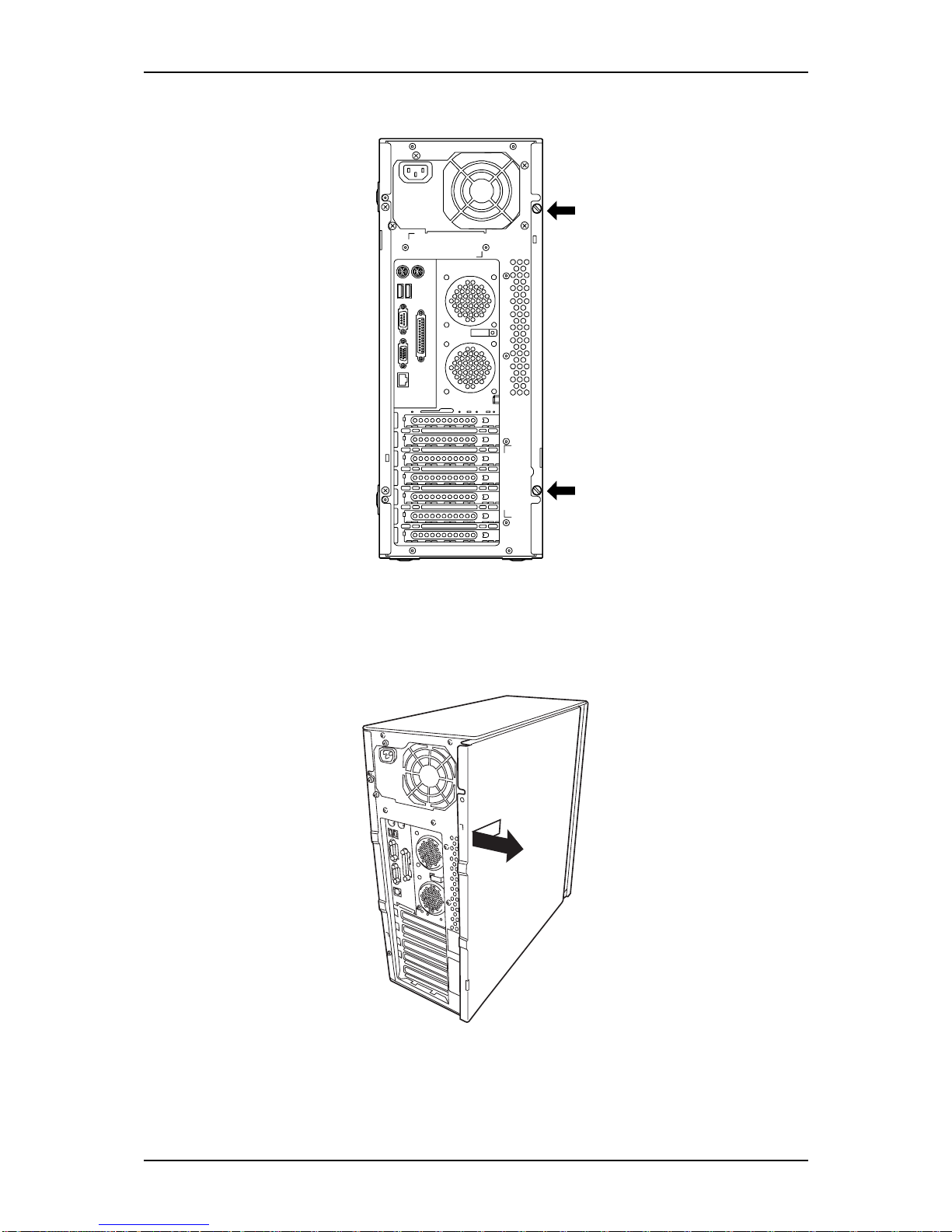
NS170 User Guide - Upgrading Your Server
4 - 5
4. Remove the two thumb screws located on the back of your system.
Figure 4 - 2 : Removing the Thumb Screws
5. Carefully slide the cover about two centimetres towards the back of the unit.
Please note that you may find this procedure easier to follow if you lay the unit
on the left side..
Figure 4 - 3 : Removing the Right Side Door
6. Lift the cover away from the computer
Page 86
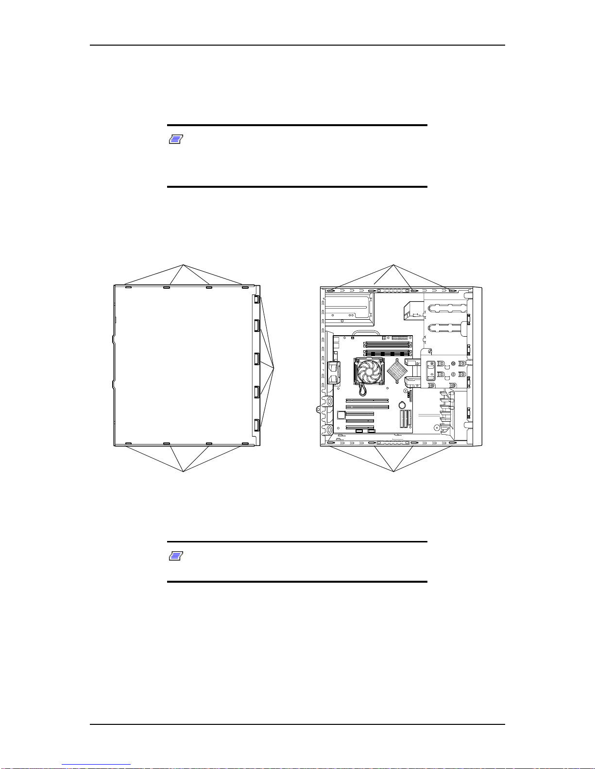
NS170 User Guide - Upgrading Your Server
4 - 6
Replacing the Right Side Door
Avoid damaging your system: before replacing the cover, make sure no cables or other
devices protrude from the chassis.
Note: If you have previously removed the front panel, be
sure to fasten it securely to the chassis before restoring the
cover. The front panel must be securely connected to the
chassis before you replace the cover.
1. Examine the interior side of the cover, and notice the 4 metal hooks located on
two opposite edges (A), and the 5 bigger hooks located on a third edge (B).
Notice the corresponding holes on the chassis (C).
Figure 4 - 4 : Locating Hooks and Holes
Note: Your server may slightly differ from the picture shown
here.
2. Leaving about 1 centimetre to slide the cover forward, lay the cover on the
chassis, and check that the metal hooks are ready to be inserted into their
C
C
A
A
B
Page 87
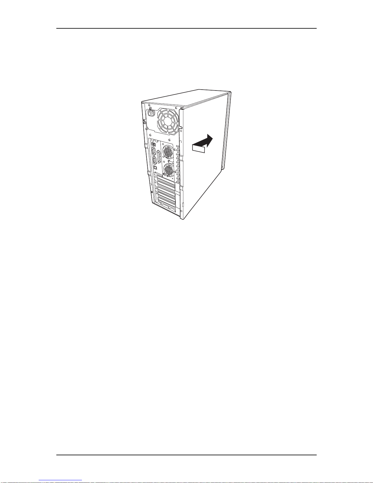
NS170 User Guide - Upgrading Your Server
4 - 7
corresponding slots. You may find this procedure easier to follow if you lay the
unit on the left side.
3. Make sure the cover is properly inserted; the cover, the chassis and the front
panel should fit squarely together.
4. Secure the two thumb screws in their respective holes.
Figure 4 - 5 : Replacing the Right Side Door
Page 88
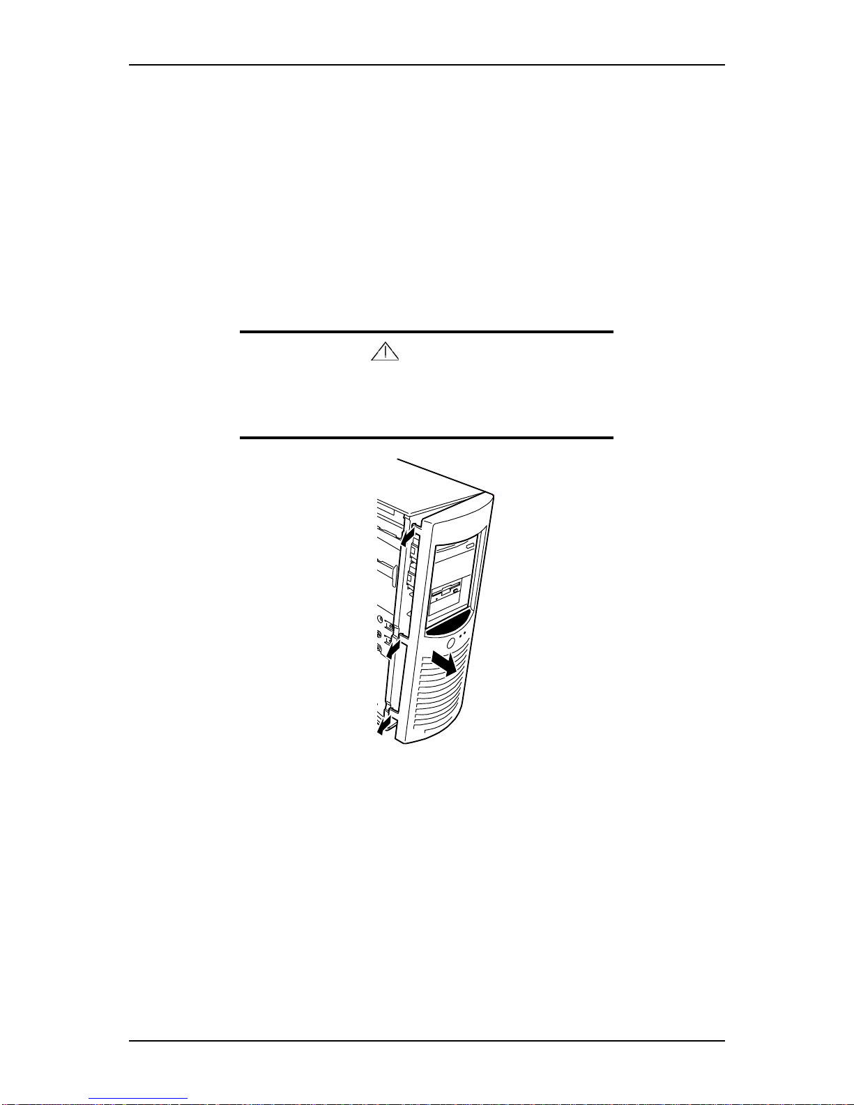
NS170 User Guide - Upgrading Your Server
4 - 8
Removing and Replacing the Front Panel
The front panel must be removed to install or remove the hard disk drive and 5.25-inch
device.
Removing the Front Panel
1. Remove the right side door. See “Removing or Installing the Right Side Door”
on page 4
2. Pull the release tabs (3) at the left end of the front panel toward you so that the
tabs are removed from the frame of the server.
Caution
Only pull out the tabs a little.
Pulling out the tabs toward you excessively would damage the
hooks fixing the right end of the front panel.
Figure 4 - 6 : Removing the Left Tabs
3. Gently pull the right side of the front panel toward you in order to free three
more pop-in tabs.
Page 89
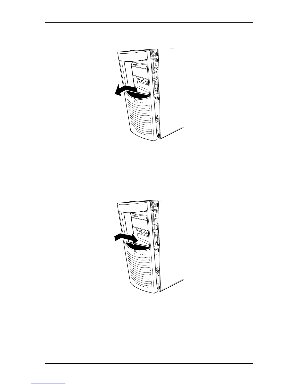
NS170 User Guide - Upgrading Your Server
4 - 9
4. Once the right side is free, pivot the front panel toward you until it is totally
released. Be careful not to damage the switches and LEDs board when pulling.
Figure 4 - 7 : Releasing the Right Tabs
Replacing the Front Panel
1. Insert the three tabs located on the right end of the front panel into their
respective slots. You may have to slightly pivot the front panel to aid the
process.
Figure 4 - 8 : Inserting the Right Tabs
Page 90
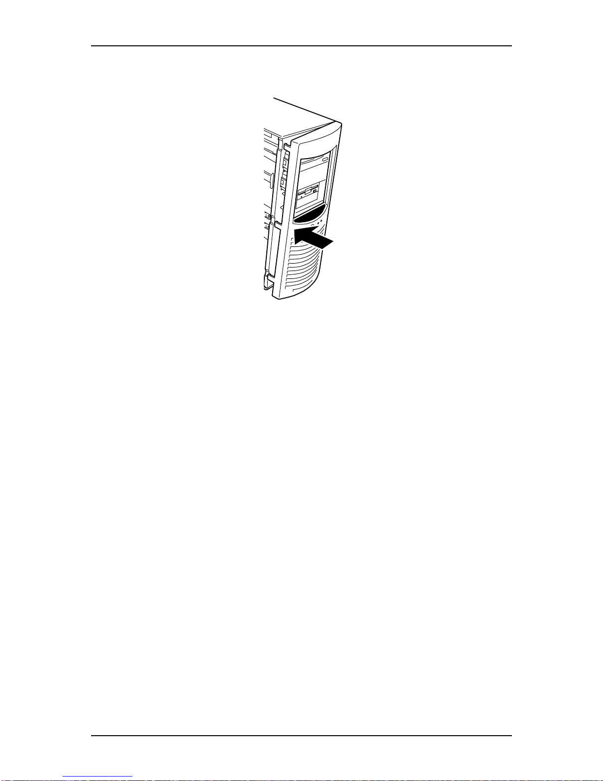
NS170 User Guide - Upgrading Your Server
4 - 10
2. Gently press on the left side of the front panel until the 3 remaining tabs are
securely inserted into their slots.
Figure 4 - 9 : Installing the Front Panel
3. Replace the right side door. See “Removing or Installing the Right Side Door”
on page 4
Page 91
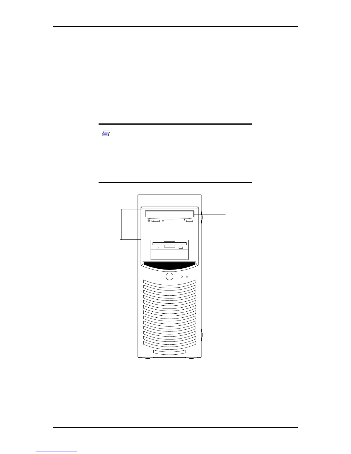
NS170 User Guide - Upgrading Your Server
4 - 11
File Device
The server has two slots on which backup devices including CD-RW, DVD-ROM and
magnetic tape drives are installed (the normally equipped CD-ROM drive occupies
another slot).
Install devices in the 5.25-inch device bay (A), also called standard cage, below the
CD-ROM drive (B).
The device bay (standard cage) is integrated to be a single chassis (the integrated
chassis is called the file bay).
Notes:
■ If a SCSI device is installed, the optional SCSI controller
board and built-in SCSI cable are required. See “Cabling the
Devices” on page 42
■ To install an IDE device, refer to table “IDE Device Configu-
ration” on page 5.
Figure 4 - 10 : Device Bay (Standard Cage)
A
B
Page 92
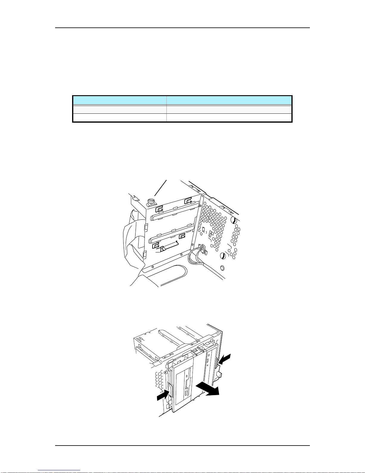
NS170 User Guide - Upgrading Your Server
4 - 12
Installing a file device
1. Provide the proper setting for the device. Refer to table “IDE Device
Configuration” on page 50.
See the table below for the settings of the devices which can be installed in the
device bay. See “Preparing the Device” on page 48
2. Remove the right side door and the front panel as described earlier in this
chapter.
3. Remove all the cables from the normally equipped CD-ROM and floppy disk
drives and the devices installed in the device bay.
4. Remove the screw (A) securing the hard disk bay.
Figure 4 - 11 : Removing the Hard Disk Bay Screw
5. Pull out the file bay from the server with the release tabs on both sides of the
file bay.
Figure 4 - 12 : Pulling out the File Bay
Table 4 - 1: 5.25-inch Devices Settings
Device 5.25-inch Device
SCSI device ID 4
IDE device MASTER on secondary IDE channel
A
Page 93
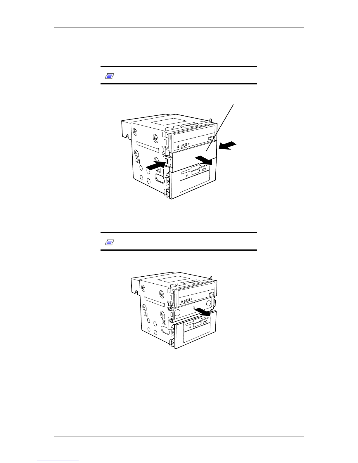
NS170 User Guide - Upgrading Your Server
4 - 13
6. Place the file bay on a flat and rigid table carefully.
7. Push the tabs on both sides of the dummy cover (A) to remove the cover.
Note: Save the removed dummy cover carefully.
Figure 4 - 13 : Removing the Dummy Cover
8. Remove the EMI cover.
Note: Save the removed EMI cover carefully.
Figure 4 - 14 : Removing the EMI Cover
A
Page 94
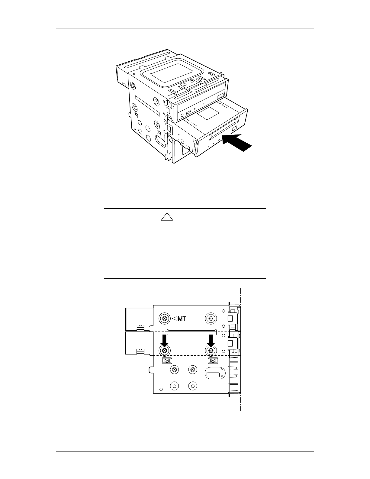
NS170 User Guide - Upgrading Your Server
4 - 14
9. Insert a file device into the file bay.
Figure 4 - 15 : Inserting a File Device
10. Align the screw holes on the device with those on the file bay and secure the
device by using the four screws provided with the device.
Caution
■ Use the screws provided with the optional device to secure
it. If not, use the screws provided with the server. Using
screws longer than the required length may cause the
device to be damaged.
■ Align the front face of the device to be installed with the front
face of the normally equipped CD-ROM drive.
Figure 4 - 16 : Aligning Screws
Page 95
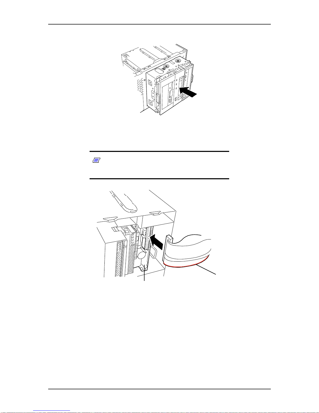
NS170 User Guide - Upgrading Your Server
4 - 15
11. Insert the file bay into the server and push it until a click occurs to lock it.
Figure 4 - 17 : Pushing the File Bay
12. Connect the interface and power cables to the 5.25-inch device installed from
one side of the server. See “Cabling the Devices” on page 42
Note: Connect the interface cable of the floppy disk drive
(A) so that the end with the red line (B) indicating pin 1 faces the
motherboard.
Figure 4 - 18 : Connecting Cables
13. Assemble the server.
14. If a SCSI device is installed, set the parameters including the transmission rate
using the BIOS utility of the SCSI controller. Refer to the manual provided
with the SCSI controller for details.
Removing a file device
The file device can be removed in the reverse order of the installation. If the device is
removed but not installed again, install the EMI and dummy covers.
B
A
Page 96
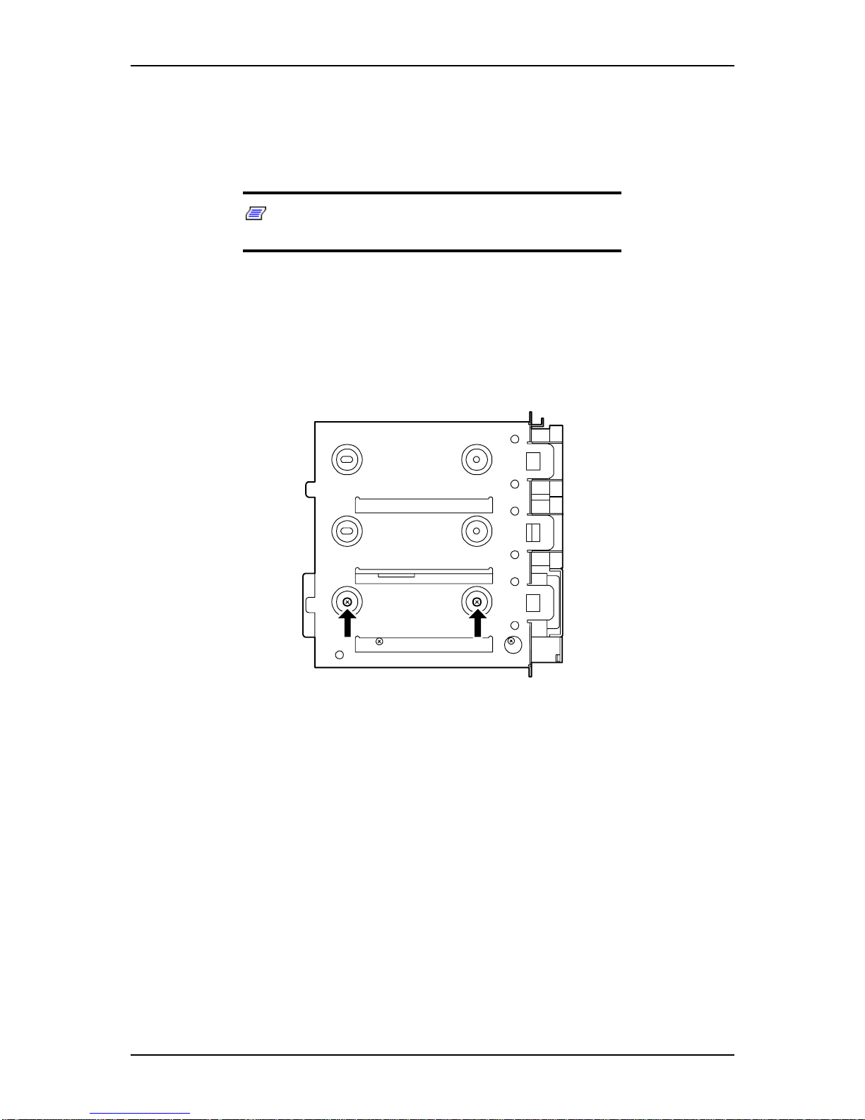
NS170 User Guide - Upgrading Your Server
4 - 16
Expansion File Device Bay
The optional expansion file device bay includes three 5.25-inch single-height devices
and one slim CD-ROM drive.
Note: An optional 5.25-inch to 3.5-inch converter can be
used to insert a 3.5-inch floppy disk drive.
Installing a File Device
1. Remove the standard file bay from the server. See "File Device" described
earlier in this chapter.
2. Remove the three screws securing the floppy disk drive to the standard file bay.
Save the screws for installation procedure.
Page 97
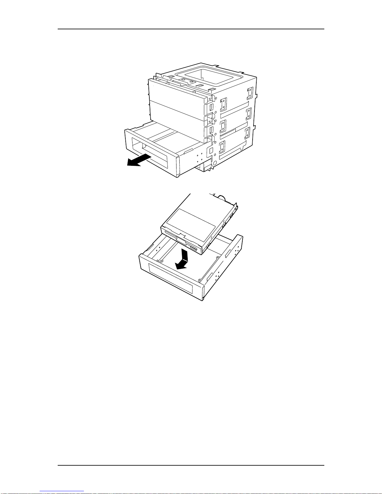
NS170 User Guide - Upgrading Your Server
4 - 17
3. Pull the floppy disk drive out of the standard file bay. Save the standard file bay
for future use.
4. Remove two screws on both sides of the expansion file bay.
5. Pull the floppy disk drive carrier out of the expansion file bay.Place the floppy
disk drive into the floppy disk drive carrier.
6. While holding the floppy disk drive in place, turn the carrier upside down.
7. Line up the screw holes in the carrier with the screw holes in the drive.
Page 98
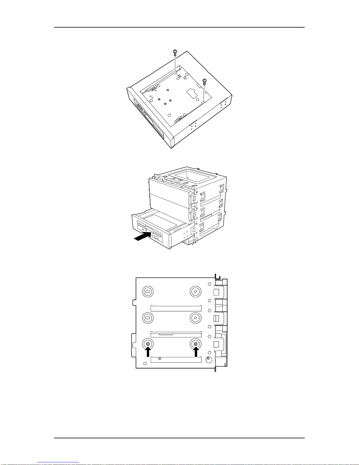
NS170 User Guide - Upgrading Your Server
4 - 18
8. Fix the floppy disk drive with two of the three screws removed in Step 2.
9. Slide the floppy disk drive carrier into the expansion file bay.
10. Secure the floppy disk drive to the expansion file bay with the screws
previously removed in Step 4.
11. Install the 5.25-inch file device(s) into the expansion file bay. See "File
Device" described earlier in this chapter.
Page 99
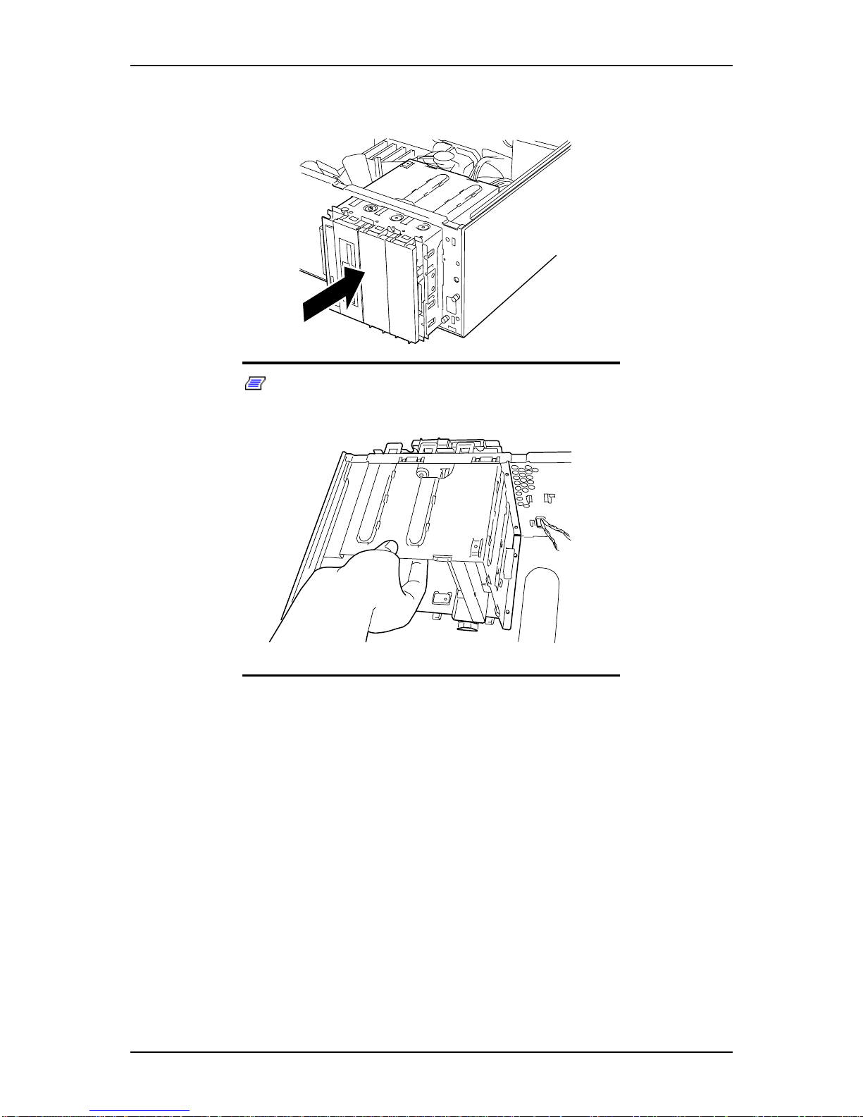
NS170 User Guide - Upgrading Your Server
4 - 19
12. Insert the file bay into the server then push the file bay until a click occurs.
The file bay is locked.
Note: If the expansion file bay cannot be inserted
completely, pull the file bay up while inserting the bay into the
server chassis.
Page 100
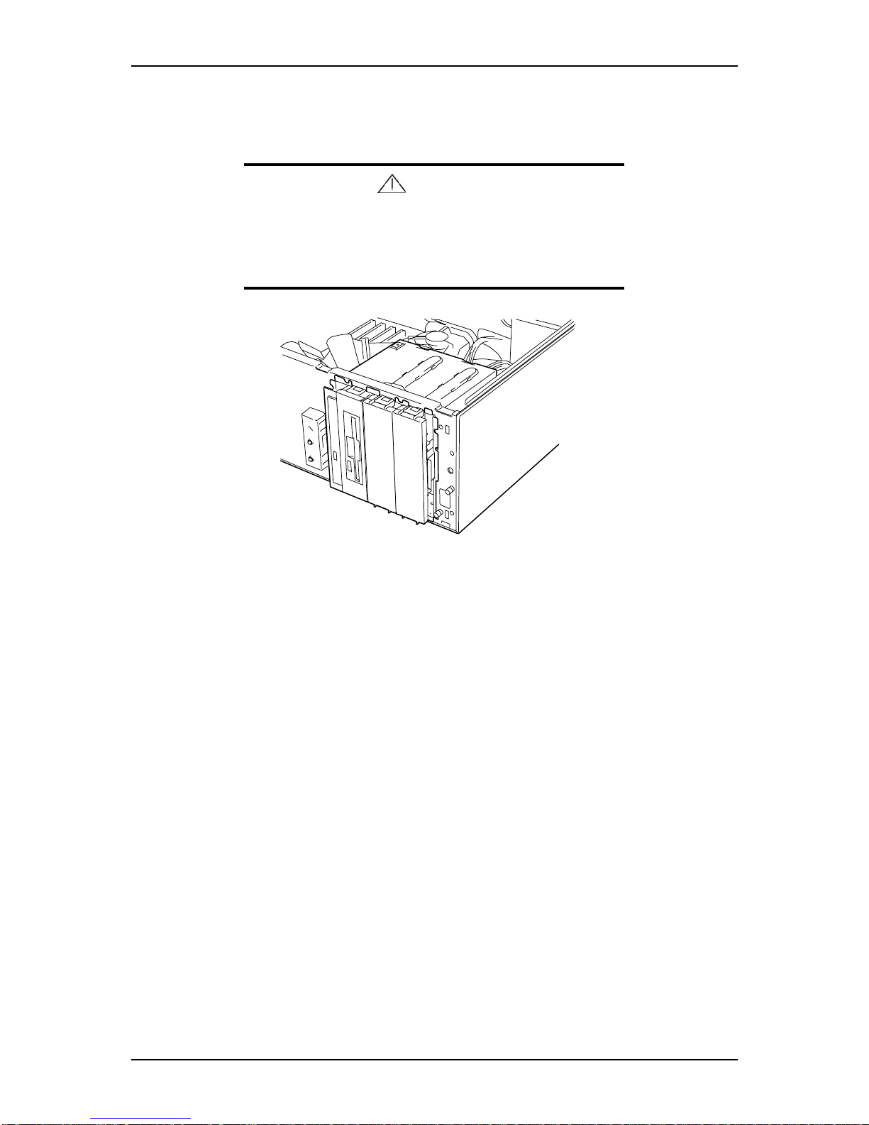
NS170 User Guide - Upgrading Your Server
4 - 20
13. Connect the interface and power cables to the 5.25-inch device installed from
one side of the server. See “Cabling the Devices” on page 42
Caution
The power relay cable is connected to the power connector of
the slim CD-ROM drive.
Connect the power cable from the power supply to the power
relay cable.
14. Assemble the server.
15. If a SCSI device is installed, set the parameters including the transmission rate
using the BIOS utility of the SCSI controller. Refer to the manual provided
with the SCSI controller for details.
16. Install the device driver for the installed device. Refer to the manual provided
with the device for details.
Removing a File Device
The expansion file bay can be removed in the reverse order of the installation.
 Loading...