

Page 1
NEC Display Solutions of America, Inc.
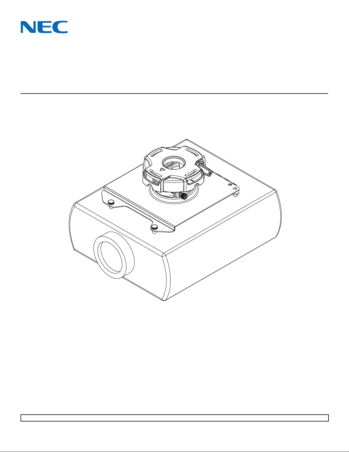
Installation and Assembly Manual:
Custom Ceiling Mount for NEC NP905, NP901W and
VT800 Projectors
Model: NP900CM
Features:
• ImageLockTM alignment prevents picture sag or drift
• Wrench access slot for easier flush mount installations
• Exclusive aluminum track quick release
Visit the Peerless Web Site at www.peerlessmounts.com
1 of 10
Maximum Load Capacity: 50 lb (22.7 kg)
ISSUED: 03-06-08 SHEET #: 055-9255-1
For customer care call 1-800-865-2112 or 708-865-8870.
Page 2
NOTE: Read entire instruction sheet before you start installation and assembly.
WARNING
• Do not begin to install your Peerless product until you have read and understood the instructions and warnings contained in this Installation Sheet. If you have any questions regarding any of the instructions or warnings, call Peerless
customer care at 1-800-729-0307.
• This product should only be installed by someone of good mechanical aptitude, has experience with basic building
construction, and fully understands these instructions.
• Make sure that the supporting surface will safely support the combined load of the equipment and all attached hardware and components.
• Never exceed the Maximum Load Capacity.
• Always use an assistant or mechanical lifting equipment to safely lift and position equipment.
• Tighten screws firmly, but do not overtighten. Overtightening can damage the items, greatly reducing their holding
power. See suggested torque values where applicable within these instructions.
• This product is intended for indoor use only. Use of this product outdoors could lead to product failure and personal
injury.
CAUTION
• It is the responsibility of the installer to ensure that the
projector is properly ventilated.
Tools Needed for Assembly
• stud finder ("edge to edge" stud finder is recommended)
• phillips screwdriver
• drill
• 1/4" bit for concrete surface
• 5/32" bit for wood studs
• open end wrench
• level
Table of Contents
Parts List .................................................................................................................................................................... 3
Installation to Extension Columns / Ceiling Plate ........................................................................................................ 4
Installation to Wood Joist Ceilings .............................................................................................................................. 5
Installation to Concrete Ceilings .................................................................................................................................. 6
Installation to Threaded Rods ...................................................................................................................................... 7
Attaching Adapter Plate to Projector ........................................................................................................................... 8
Attaching Adapter Plate to Projector Mount ................................................................................................................ 9
Projector Alignment ...................................................................................................................................................10
ISSUED: 03-06-08 SHEET #: 055-9255-1
Visit the Peerless Web Site at www.peerlessmounts.com
2 of 10
For customer care call 1-800-865-2112 or 708-865-8870.
Page 3
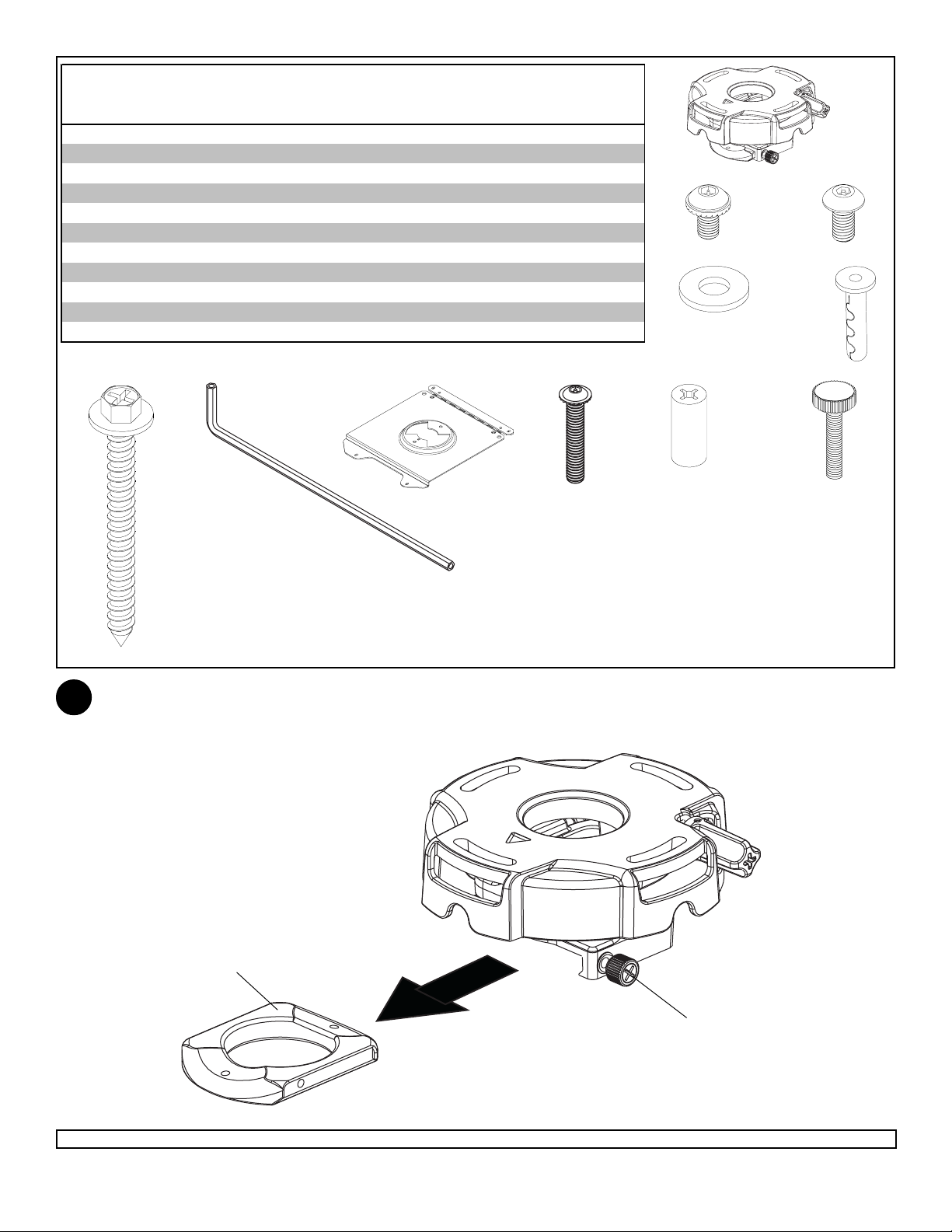
Before you start check the parts list to insure all of the parts shown are included.
Parts List
Description Qty. Pa rt #
projector mount assembly 1 055-2804
A
4 mm security allen wrench 1 560-9646
B
#10-32 x 3/8" serrated washer head socket pin screw 2 520-2151
C
#10-32 x 1/4" soc ket pin screw 1 520-2196
D
flat washer 2 540-1078
E
#14 x 2.5 phillips hex head wood screw 2 5S1-015-C04
F
concrete anchor 2 590-0097
G
AA
BB
CC
DD
NOTE: Actual parts may appear slightly different than illustrated.
F
adapter plate 1 055-2815
M3 x 25 mm serrated socket pin screw 2 510-2127
retaining spacer 4 590-2300
M3 x 25 mm knurled knob 2 560-7139
B
AA
BB
CC
A
C
E
D
G
DD
Disengage connection block from projector mount assembly (A) by unscrewing captive screw and sliding out
1
connection block as shown.
CONNECTION BLOCK
Visit the Peerless Web Site at www.peerlessmounts.com
A
3 of 10
CAPTIVE SCREW
ISSUED: 03-06-08 SHEET #: 055-9255-1
For customer care call 1-800-865-2112 or 708-865-8870.
Page 4
Installation to Extension Column / Ceiling Plate
NOTE: Refer to accompanying instructions with ceiling plates (sold separately) for installing these models to
2
ceiling.
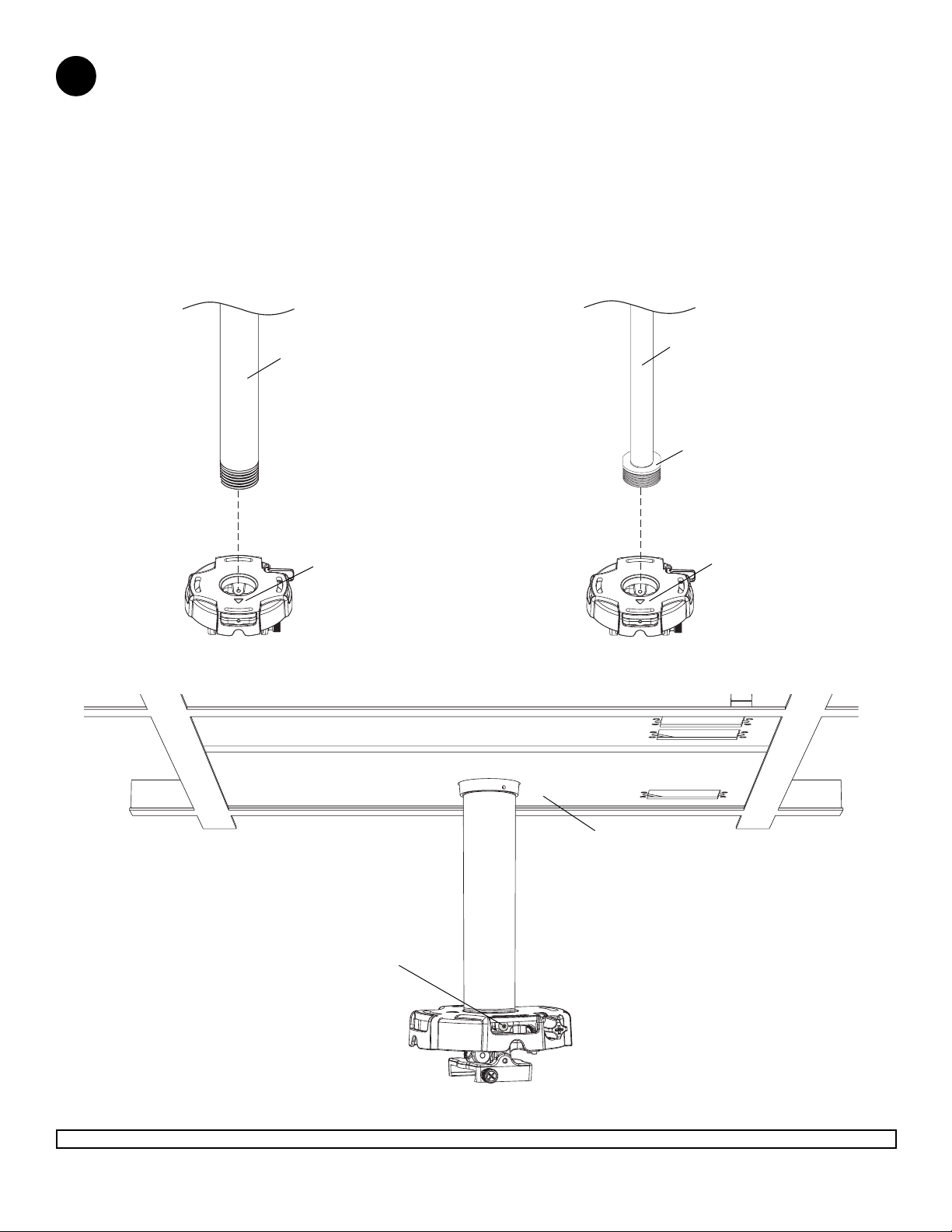
Screw projector mount assembly (A) onto extension column as shown in figure 2.1.
NOTE: For 3/4" extension columns, reducer ACC 913 (not included) will be required as shown in figure 2.2. Tighten
swivel stop screw against extension column, flush mount tube or reducer using 4 mm security allen wrench (B) as
shown in figure 2.3.
NOTE: Swivel stop screw is used to jam against threads of extension column, flush mount tube or reducer to
prevent any excess movement of projector mount assembly (A). Do not overtighten screw; overtightening screw will
damage threads making it difficult to separate products.
Skip to step 3.
A
1 1/2" EXTENSION
COLUMN
(SOLD SEPARATELY)
UL LISTED EXT OR ADJ
SERIES)
ARROW
INDICATES
FRONT OF
MOUNT
A
3/4" EXTENSION COLUMN
(SOLD SEPARATELY)
ACC 913
(NOT UL LISTED)
(SOLD SEPARATELY)
ARROW
INDICATES
FRONT OF
MOUNT
fig. 2.1 fig. 2.2
SWIVEL STOP
SCREW
Visit the Peerless Web Site at www.peerlessmounts.com
4 of 10
CMJ 455
(SOLD SEPARATELY)
fig. 2.3
ISSUED: 03-06-08 SHEET #: 055-9255-1
For customer care call 1-800-865-2112 or 708-865-8870.
Page 5
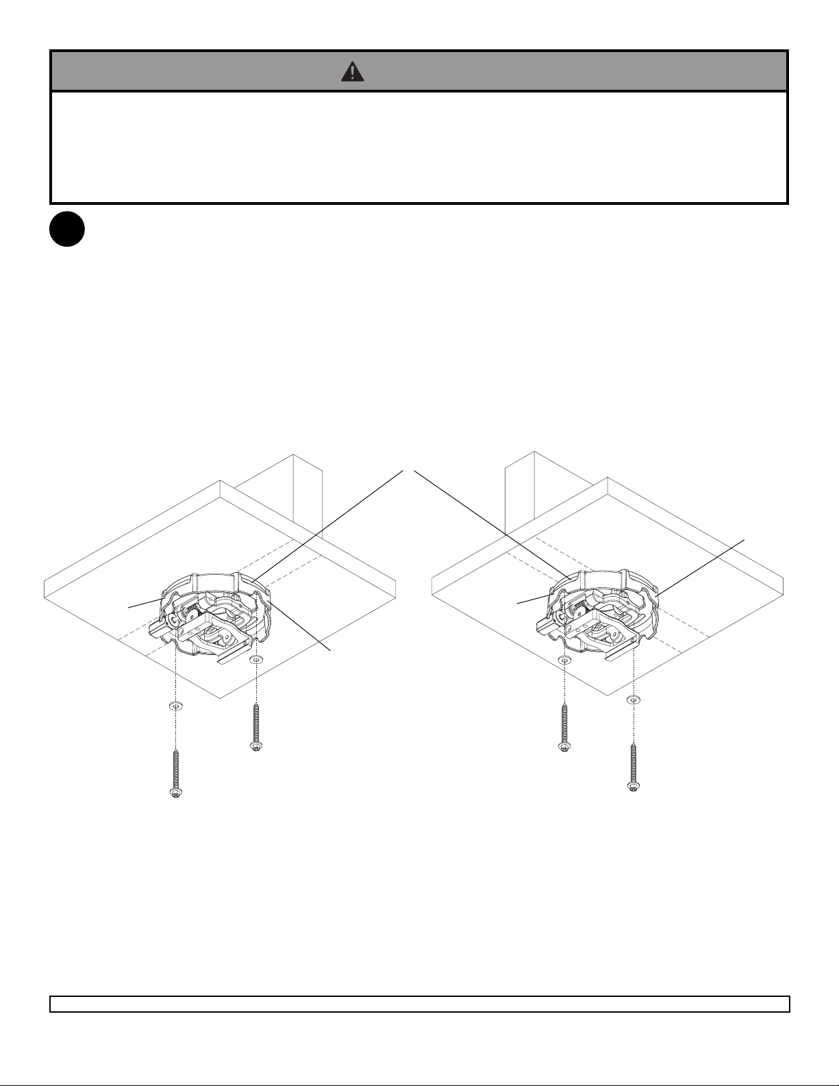
Installation To Wood Joist Ceilings
WARNING
• Tighten wood screws so that projector mount assembly is firmly attached, but do not overtighten. Overtightening can
damage the screws, greatly reducing their holding power.
• Never tighten in excess of 80 in • lb (9 N.M.).
• Make sure that mounting screws are anchored into the center of the studs. The use of an "edge to edge" stud finder is
highly recommended.
Place projector mount assembly (A) on ceiling as a template and mark the center of the two mounting holes. Make
2
sure that the mounting holes are in the center of the wood joist. Drill two 5/32" (4 mm) dia. holes to a minimum
depth of 2.5" (64 mm). Attach projector mount assembly (A) with two #14 x 2.5" (6 mm x 65 mm) wood screws (F)
and two flat washers (E) as shown in figure 2.4 or figure 2.5 depending on joist orientation. Tighten wood screws (D)
using 3/8" (10 mm) socket wrench, phillips screwdriver or 10mm open end wrench until projector mount
assembly (A) is firmly attached.
Skip to step 3.
ACCESS SLOT FOR
OPEN END WRENCH
ALLOWS TIGHTENING
WOOD JOIST
OF WOOD SCREW (D)
WITHOUT REMOVING
PROJECTOR
WOOD JOIST
A
E
F
FRONT OF
MOUNT
fig. 2.4
FRONT OF
MOUNT
A
E
F
fig. 2.5
Visit the Peerless Web Site at www.peerlessmounts.com
5 of 10
ISSUED: 03-06-08 SHEET #: 055-9255-1
For customer care call 1-800-865-2112 or 708-865-8870.
Page 6
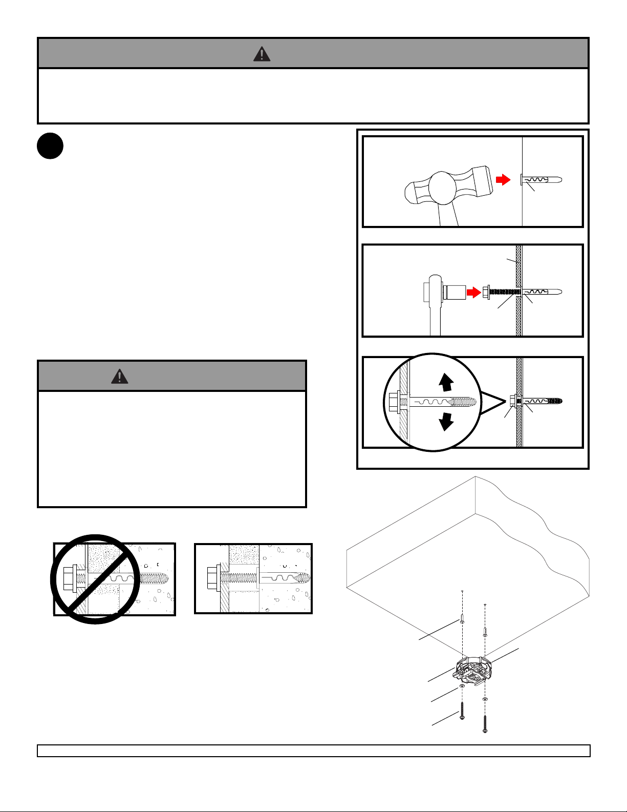
Installation to Concrete Ceilings
WARNING
• Tighten wood screws firmly, but do not overtighten. Overtightening can damage the screws, greatly reducing their
holding power.
• Never tighten in excess of 80 in • lb (9 N.M.).
Place projector mount assembly (A) on ceiling as a
2
template and mark the center of the two mounting
holes. Drill two 1/4" (6 mm) dia. holes to a minimum
depth of 2.5" (64 mm). Attach projector mount
assembly (A) using two concrete anchors (G), two
flat washers (E), and two #14 x 2.5" wood screws (F)
as shown in fig. 2.6 and 1, 2 and 3 (right). Tighten
wood screws (F) using 3/8" (10 mm) socket wrench,
phillips screwdriver or 10mm open end wrench until
projector mount assembly (A) is firmly attached.
NOTE: It is the responsibility of the installer to
verify that the ceiling will safely support the
combined load of all attached hardware and
components.
Skip to step 3.
WARNING
• Concrete anchors are not intended for attachment to
concrete ceiling covered with a layer of plaster,
drywall, or other finishing material. If mounting to
concrete ceiling covered with plaster/drywall is unavoidable, plaster/drywall (up to 5/8" thick) must be
counterbored as shown below. If plaster/drywall is
thicker than 5/8", custom fasteners must be supplied
by installer.
1
concrete
ceiling
G
Drill holes and insert anchors
2
Place mount over anchors and secure with screws
3
Tighten all fasteners
F
A
F
G
G
INCORRECT
A
plaster/
CUTAWAY VIEW
Visit the Peerless Web Site at www.peerlessmounts.com
dry wall
concrete
CORRECT
A
plaster/
dry wall
concrete
6 of 10
CONCRETE CEILING
G
FRONT OF
MOUNT
A
E
fig. 2.6
F
ISSUED: 03-06-08 SHEET #: 055-9255-1
For customer care call 1-800-865-2112 or 708-865-8870.
Page 7
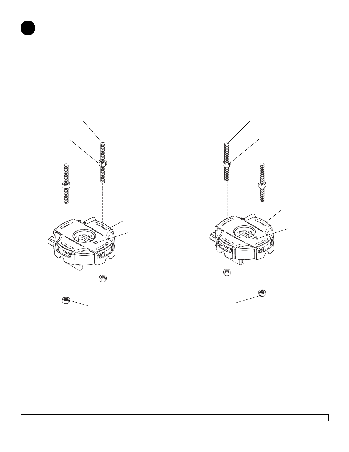
Installation to Threaded Rod
Thread two 1/4-20 hex thin nylon-insert locknuts (not included) on two 1/4-20 threaded rods (not included) to the
2
desired height of projector mount assembly. Attach projector mount assembly (A) to the two 1/4-20 threaded rods
using two 1/4-20 hex thin nylon-insert locknuts as shown in figure 2.7 or figure 2.8.
1/4-20 THREADED ROD
(NOT INCLUDED)
1/4-20 THREADED ROD
(NOT INCLUDED)
1/4-20 HEX THIN
NYLON-INSERT
LOCKNUT
(NOT INCLUDED)
fig. 2.7
1/4-20 HEX THIN
NYLON-INSERT
LOCKNUT
(NOT INCLUDED)
A
ARROW
INDICATES
FRONT OF
MOUNT
1/4-20 HEX THIN
NYLON-INSERT
LOCKNUT
(NOT INCLUDED)
1/4-20 HEX THIN
NYLON-INSERT
LOCKNUT
(NOT INCLUDED)
A
ARROW
INDICATES
FRONT OF
MOUNT
fig. 2.8
Visit the Peerless Web Site at www.peerlessmounts.com
7 of 10
ISSUED: 03-06-08 SHEET #: 055-9255-1
For customer care call 1-800-865-2112 or 708-865-8870.
Page 8
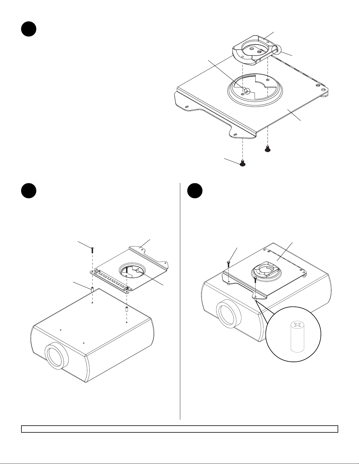
Attaching Adapter Plate to Projector
Align shoulder on connection block opposite notch
3
in adapter plate. Attach adapter plate to connection
block from projector mount assembly (A) using two
#10-32 x 3/8" serrated washer head socket pin
screws (C) as shown in figure 3.1.
NOTCH INDICATES
FRONT OF PROJECTOR
CONNECTION BLOCK
SHOULDER
AA
*Notch indicates front of projector.
4
Flip projector upside down and attach adapter
plate (AA) using two serrated socket pin screws (BB)
and retaining spacers (CC) as shown below. Tighten
using 4 mm allen wrench (DD).
BB
CC
AA
C
Secure adapter plate with two knurled knobs (DD)
and retaining spacers (CC) in remaining hole.
5
NOTE: Retaining spacers (CC) go between the
projector and adapter plate (AA).
fig. 3.1
AA
DD
*
CC
Visit the Peerless Web Site at www.peerlessmounts.com
8 of 10
ISSUED: 03-06-08 SHEET #: 055-9255-1
For customer care call 1-800-865-2112 or 708-865-8870.
Page 9
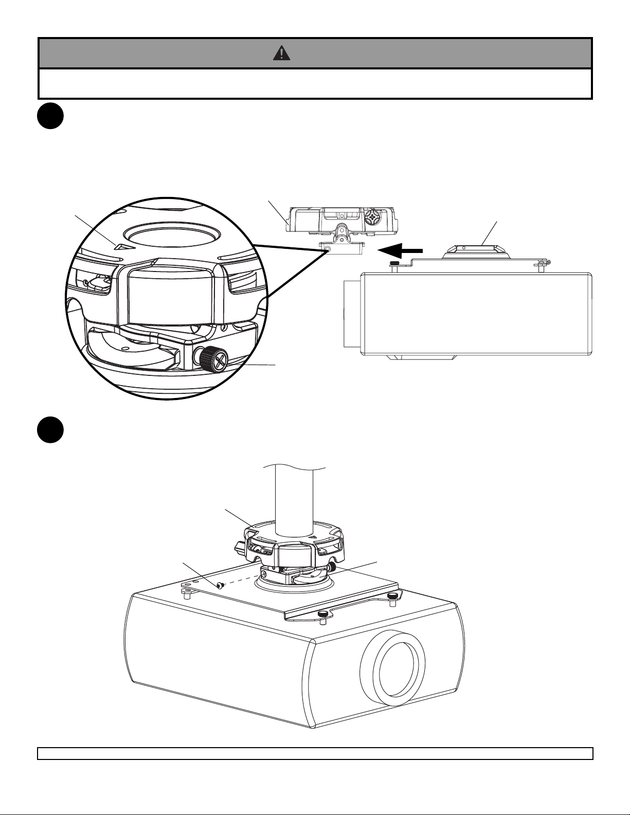
Attaching Adapter Plate to Projector Mount
WARNING
• Do not lift more weight than you can handle. Use additional man power or mechanical lifting equipment to safely handle
placement of the screen.
Slide connection block with projector into projector mount assembly (A) as shown. Tighten captive screw to secure
6
projector to projector mount assembly (A).
ARROW
INDICATES
FRONT OF
MOUNT
IMPORTANT: For security installations, insert one #10-32 x 1/4" socket pin screw (D) through projector mount
7
assembly (A) and into connection block as shown. Tighten screw using 4mm security allen wrench (B).
FRONT OF MOUNT
CAPTIVE SCREW
A
CONNECTION BLOCK
A
D
Visit the Peerless Web Site at www.peerlessmounts.com
9 of 10
CONNECTION BLOCK
ISSUED: 03-06-08 SHEET #: 055-9255-1
For customer care call 1-800-865-2112 or 708-865-8870.
Page 10
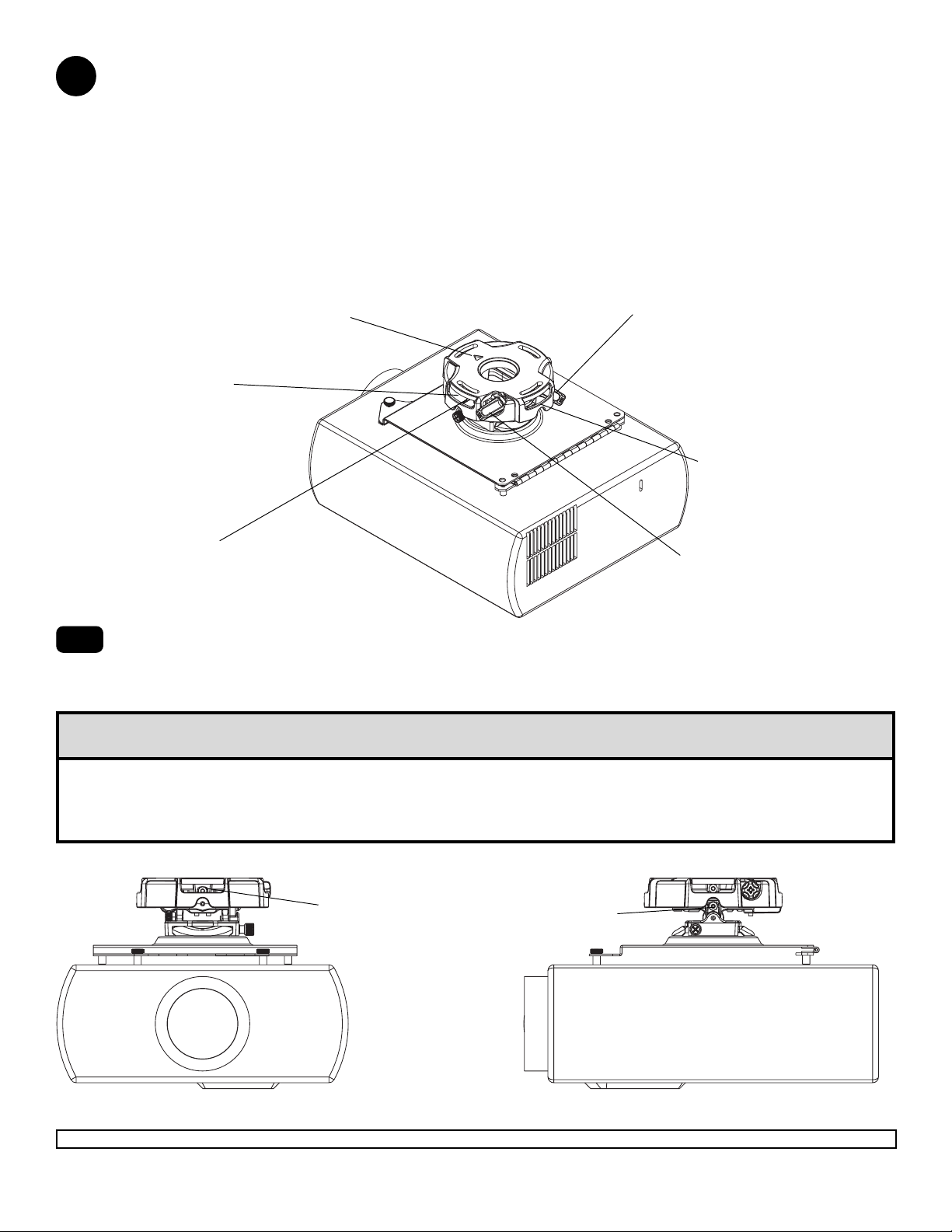
Projector Alignment
To adjust yaw (swivel) for wood stud, concrete ceiling, and threaded rod mounting applications:
8
Loosen wood screws (F) if flush mounted to wood joists (step 3) or concrete ceilings (step 4), or loosen locknuts on threaded rods (step 5), until projector mount can be rotated. Rotate mount to desired position and
retighten screws or locknuts.
To adjust yaw (swivel) for extension column applications: Loosen screw on projector mount assembly (A)
indicated below until projector mount can be rotated. Rotate mount to desired position and retighten screw.
To adjust pitch (forward and backward tilt): Turn knob on back of mount as shown below. Pull knob out and
turn by hand for easy adjustment or insert #2 phillips screwdriver in end of knob and turn.
To adjust roll (side to side tilt): Turn knob on side of mount as shown below. Pull knob out and turn by hand
for easy adjustment or insert #2 phillips screwdriver in end of knob and turn.
ARROW INDICATES
FRONT OF MOUNT
ACCESS SLOT FOR
OPEN END WRENCH
ALLOWS TIGHTENING
OF WOOD SCREW (F)
WITHOUT REMOVING
PROJECTOR
A
KNOB FOR PITCH
ADJUSTMENT
BACK OF MOUNT
8-1
SCREW FOR YAW (SWIVEL) STOP
(REFER TO STEP 2, INSTALLATION
TO EXTENSION COLUMNS, FIG. 2.3)
To prevent tampering with the pitch and roll adjustments: Tighten the two tamper resistant security screws
KNOB FOR ROLL
ADJUSTMENT
on the projector mount assembly using 4 mm security allen wrench (B) to lock the pitch and roll adjustments as
shown below.
Note: Tighten screws firmly, but do not overtighten. Overtightening can damage the mount.
CAUTION
• Do not adjust pitch or roll while tamper resistant security screws are fully engaged.
• Loosen the two tamper resistant security screws one complete turn before adjusting the projector mount assembly or
damage may occur.
TO LOCK ROLL TIGHTEN
TAMPER RESISTANT
SECURITY SCREW
TO LOCK PITCH TIGHTEN
TAMPER RESISTANT
SECURITY SCREW
FRONT VIEW
Visit the Peerless Web Site at www.peerlessmounts.com
SIDE VIEW
10 of 10
For customer care call 1-800-865-2112 or 708-865-8870.
All other brand and product names are trademarks or registered trademarks of their respective owners.
ISSUED: 03-06-08 SHEET #: 055-9255-1
© 2008, Peerless Industries, Inc. All rights reserved.
 Loading...