

Page 1

Projector
NP4100/NP4100W
User’s Manual
Page 2

Second edition, March 2009
• DLP, BrilliantColor and DynamicBlack are trademarks of Texas Instruments.
• IBM is a trademark or registered trademark of International Business Machines Corpora-
tion.
• Macintosh, Mac OS X and PowerBook are trademarks of Apple, Inc., registered in the
U.S. and other countries.
• Windows, PowerPoint, Internet Explorer, Windows 98, Windows Me, Windows 2000,
Windows XP or Windows Vista are trademarks or registered trademarks of Microsoft
Corporation.
• VESA is a registered trademark of Video Electronics Standards Association.
• Trademark PJLink is a trademark applied for trademark rights in Japan, the United States
of America and other countries and areas.
• Other product and company names mentioned in this user's manual may be the trademarks or registered trademarks of their respective holders.
Notes
(1) The contents of this user’s manual may not be reprinted in part or whole without permis-
sion.
(2) The contents of this user’s manual are subject to change without notice.
(3) Great care has been taken in the preparation of this user’s manual; however, should you
notice any questionable points, errors or omissions, please contact us.
(4) Notwithstanding article (3), NEC will not be responsible for any claims on loss of profit or
other matters deemed to result from using the Projector.
Page 3

Important Information
Safety Cautions
Precautions
Please read this manual carefully before using your NEC NP4100/NP4100W projector
and keep the manual handy for future reference. Your serial number is located on the
bottom of your projector.
Record it here:
CAUTION:
To turn off main power, be sure to remove the plug from power outlet. The
power outlet socket should be installed as near to the equipment as possible,
and should be easily accessible.
CAUTION:
• TO PREVENT SHOCK, DO NOT OPEN THE CABINET.
• THERE ARE HIGH-VOLTAGE COMPONENTS INSIDE.
• REFER SERVICING TO QUALIFIED SERVICE PERSONNEL.
This symbol warns the user that un-insulated voltage within the unit may be
sufficient to cause electrical shock. Therefore, it is dangerous to make any
kind of contact with any part inside of the unit.
This symbol alerts the user that important information concerning the operation and maintenance of this unit has been provided.
The information should be read carefully to avoid problems.
WARNING:
To prevent fire or shock, do NOT expose this unit to rain or moisture. Do NOT use
this unit’s plug with an extension cord or in an outlet unless all the prongs can be
fully inserted.
DOC Compliance Notice (for Canada only)
This Class B digital apparatus meets all requirements of the Canadian InterferenceCausing Equipment Regulations.
Machine Noise Information Regulation - 3. GPSGV (for Germany only)
The highest sound pressure level is less than 70 dB (A) in accordance with EN ISO
7779.
i
Page 4

Important Information
g
s
)
j
y
r
y
y
g
Laser Rating
This label is on the side of the remote control.
This mark is on the top
of the remote control.
CAUTION
CAUTION
Use of controls or adjustments or performance of procedures other than
those specified herein may result in hazardous radiation exposure.
Do not look into the laser pointer while it is on and do not point the laser
beam at a person. Serious injury could result.
Disposing of your used product
EU-wide le
that used electrical and electronic products carrying the mark (left
must be disposed of separately from normal household waste. This
includes pro
ou dispose of such products, please follow the guidance of you
local authority and/or ask the shop where you purchased the product.
After collecting the used products, the
proper wa
ative impact such as mercury contained in a lamp to the human
ne
health and the environment at the minimum level. The mark on the
electrical and electronic products only applies to the current European Union Member States.
islation as implemented in each Member State require
ectors and their electrical accessories or lamps. When
. This effort will help us reduce the wastes as well as the
are reused and recycled in a
WARNING TO CALIFORNIA RESIDENTS:
Handling the cables supplied with this product will expose you to lead, a chemical known
to the State of California to cause birth defects or other reproductive harm. Wash hands
after handling.
ii
Page 5

Important Information
RF Interference (for USA only)
WARNING:
The Federal Communications Commission does not allow any modifications or
changes to the unit EXCEPT those specified by NEC Display Solutions of America, Inc. in this manual. Failure to comply with this government regulation could
void your right to operate this equipment. This equipment has been tested and
found to comply with the limits for a Class B digital device, pursuant to Part 15 of
the FCC Rules. These limits are designed to provide reasonable protection
against harmful interference in a residential installation. This equipment generates, uses, and can radiate radio frequency energy and, if not installed and used
in accordance with the instructions, may cause harmful interference to radio
communications. However, there is no guarantee that interference will not occur in
a particular installation.
If this equipment does cause harmful interference to radio or television reception,
which can be determined by turning the equipment off and on, the user is encouraged to try to correct the interference by one or more of the following measures:
Reorient or relocate the receiving antenna.
Increase the separation between the equipment and receiver.
Connect the equipment into an outlet on a circuit different from that to which the
receiver is connected.
Consult the dealer or an experienced radio / TV technician for help.
For UK only: In UK, a BS approved power cable with molded plug has a Black (five
Amps) fuse installed for use with this equipment. If a power cable is not supplied with
this equipment please contact your supplier.
Important Safeguards
These safety instructions are to ensure the long life of your projector and to prevent fire
and shock. Please read them carefully and heed all warnings.
Installation
• Do not place the projector in the following conditions:
On an unstable cart, stand, or table.
Near water, baths or damp rooms.
In direct sunlight, near heaters or heat radiating appliances.
In a dusty, smoky or steamy environment.
On a sheet of paper or cloth, rugs or carpets.
iii
Page 6

Important Information
• If you wish to have the projector installed on the ceiling:
Do not attempt to install the projector yourself.
The projector must be installed by qualified technicians in order to ensure proper
operation and reduce the risk of bodily injury.
In addition, the ceiling must be strong enough to support the projector and the in-
stallation must be in accordance with any local building codes.
Please consult your dealer for more information.
CAUTION:
When shipping the projector, remove the optional lens beforehand. The lens
and the lens shift mechanism may encounter damage caused by improper
handling during transportation.
Place the projector in a horizontal position
Do not put the projector on its side when the lamp is turned on. Doing so may cause
damage to the projector.
CAUTION:
Do not drop the projector on your hand or fingers while lifting the projector to
replace the filters. Doing so could injure your hand or fingers.
iv
Page 7

Important Information
Fire and Shock Precautions
• Ensure that there is sufficient ventilation and that vents are unobstructed to prevent
the build-up of heat inside your projector (see page ix, x).
• Do not try to touch the ventilation outlet on the rear as it can become heated
while the projector is turned on and immediately after the projector is turned
off.
• Prevent foreign objects such as paper clips and bits of paper from falling
into your projector. Do not attempt to retrieve any objects that might fall into your projector. Do not insert any metal objects such as a wire or screwdriver into your project.
If something should fall into your projector, disconnect it immediately and have the
object removed by qualified service personnel.
• Do not place any objects on top of the projector.
• Do not touch the power plug during a thunderstorm. Doing so can cause electrical
shock or fire.
• The projector is designed to operate on a power supply of 100-240V AC 50/60 Hz.
Ensure that your power supply fits this requirement before attempting to use your
projector.
• Do not look into the lens while the projector is on. Serious damage to your eyes could
result.
• Keep any items such as magnifying glass out of the light path of the projector. The
light being projected from the lens is extensive, therefore any kind of abnormal objects that can redirect light coming out of the lens, can cause unpredictable outcome
such as fire or injury to the eyes.
• Do not cover the lens with the black lens cap or equivalent while the projector is on.
Doing so can lead to melting of the cap and possibly burning your hands due to the
heat emitted from the light output.
• Do not place any objects, which are easily affected by heat, in front of the projector
lens or a projector exhaust vent. Doing so could lead to the object melting or getting
your hands burned from the heat that is emitted from the light output and exhaust.
• Handle the power cable carefully. A damaged or frayed power cable can cause electric shock or fire.
Do not use any power cables other than the one supplied by NEC.
Do not bend or tug the power cable excessively.
Do not place the power cable under the projector, or any heavy object.
Do not cover the power cable with other soft materials such as rugs.
Do not heat the power cable
Do not handle the power plug with wet hands.
v
Page 8

Important Information
• Turn off the projector, unplug the power cable and have the projector serviced by
qualified service personnel under the following conditions:
When the power cable or plug is damaged or frayed.
If liquid has been spilled into the projector, or if it has been exposed to rain or
water.
If the projector does not operate normally when you follow the instructions
described in this user's manual.
If the projector has been dropped or the cabinet has been damaged.
If the projector exhibits a distinct change in performance, indicating a need for
service.
• Disconnect the power cable and any other cables before carrying the projector.
• Turn off the projector and unplug the power cable if the projector is not to be used for
an extended period of time.
• When using a LAN cable:
For safety, do not connect to the connector for peripheral device wiring that might
have excessive voltage.
• Turn off the projector and unplug the power cable before cleaning the cabinet or replacing the lamp.
CAUTION:
• Always carry your projector by using the carrying handle.
• Do not use the tilt-foot for purposes other than originally intended. Misuses
such as using the tilt foot to carry or hang (from the wall or ceiling) the projector can cause damage to the projector.
• Do not send the projector in the soft case by parcel delivery service or cargo
shipment. The projector inside the soft case could be damaged.
• Do not unplug the power cable from the wall outlet or projector when the projector is powered on. Doing so can cause damage to the AC IN connector of
the projector and (or) the prong plug of the power cable.
• To turn off the AC power supply when the projector is powered on, use a
power strip equipped with a switch and a breaker.
• The projector can be unplugged during its cool down period after it is turned
off.
• Do not try to touch the ventilation outlet on the rear as it can become heated
while the projector is turned on and immediately after the projector is turned
off.
• Do not turn off the AC power for 60 seconds after the lamp is turned on and
while the POWER indicator is blinking green. Doing so could cause premature
lamp failure.
• Do not place your hands near the lens opening while shifting the lens. Shifting
the lens could pinch your fingers or hands causing injury.
vi
Page 9
Important Information
Remote Control Precautions
• Handle the remote control carefully.
• If the remote control gets wet, wipe it dry immediately.
• Avoid excessive heat and humidity.
• Do not heat, take apart, or throw batteries into fire.
• If you will not be using the remote control for a long time, remove the batteries.
• Ensure that you have the batteries' polarity (+/–) aligned correctly.
•
Do not use new and old batteries together, or use different types of batteries together.
• Dispose of used batteries according to your local regulations.
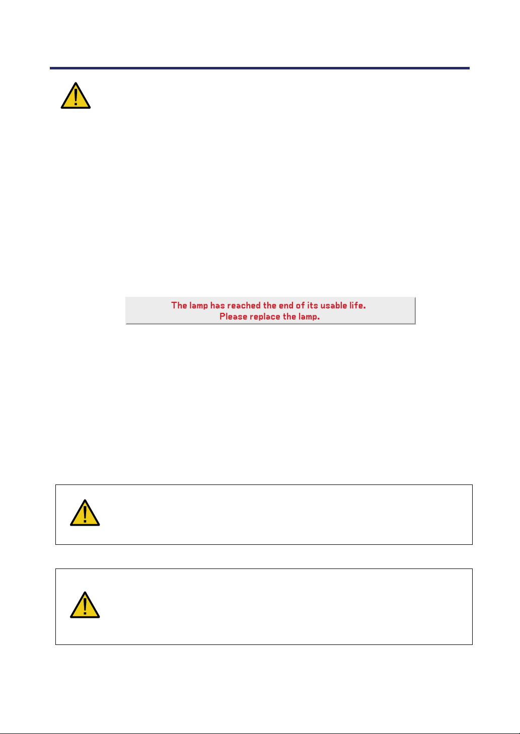
Lamp Replacement
To replace either of the lamps, follow all instructions provided on page 112.
Be sure to replace the lamp when the following is displayed on the screen:
If you continue to use the lamp after the lamp has reached the end of its usable life, the
lamp bulb may shatter, and pieces of glass may be scattered in the lamp case. Do not
touch them as the pieces of glass may cause injury.
If this happens, contact your dealer for lamp replacement.
Important Lamp Characteristic
The projector has a high-pressure mercury lamp as a light source.
A characteristic of mercury lamps is that brightness gradually decreases with age. Also
repeatedly turning the lamp on and off will increase the possibility of reduced brightness.
CAUTION:
When removing the lamp from a ceiling-mounted projector, make sure that no
one is under the projector. Glass fragments could fall if the lamp has been
burned out.
CAUTION:
In rare cases the lamp bulb may burn out during normal operation and cause
glass dust or shards to be discharged outward from the rear exhaust vent.
Do not inhale or do not touch glass dust or shards. Doing so could result in
injury.
vii
Page 10

Important Information
[Important 1] Operating the Lamp Continuously
If using the projector continuously for a long period, use of the menu (OSD) is recommended in order to properly cycle the lamps as described below.
To use the projector continuously in the dual lamp mode
Allow 2 hours per day of non usage time per lamp. Do this for both lamps at the same
time or for “Lamp 1” and “Lamp 2” at separate 2 hour intervals.
To use the projector continuously in single lamp mode
Use the two lamps (Lamp 1 and Lamp 2) alternately in a cycle of 24 hours or less.
Allow 2 hours or longer per day of no-use time for each lamp.
Contact your dealer for more details.
Note:
If using the menu, select "Off" for "Lamp Interval" from the on-screen menu
(see page 82).
viii
Page 11

Important Information
[Important 2] Clearance for Installing the Projector
Allow ample clearance between the projector and its surroundings as shown below.
Avoid installing the projector in a place where air movement from the HVAC is directed
at the projector.
Heated air from the HVAC can be taken in by the projector's intake vent. If this happens,
the temperature inside the projector will rise too high causing the over-temperature protector to automatically turn off the projectors power.
Example 1 – If there are walls on both sides of the projector.
Note:
The drawing shows the
proper clearance required
for the front, back and top of
the projector.
Example 2 – If there is a wall behind the projector.
(1) For floor installation:
(2) For ceiling mounting:
Note:
The drawing shows the
proper clearance required
for the back, sides and top
of the projector.
Note:
1. The drawing shows the
proper clearance required
for the front, sides, back and
bottom of the projector.
2. If suspending the projector 30 cm/12 inches away
from the ceiling, allow ample
clearance for all four sides
and the under the projector.
ix
Page 12

Important Information
(3) Upward or downward projection:
When using the projector in an upward projection angle, allow 1 m/ 40 inches or
greater between the exhaust vent and the wall.
When using the projector in a downward projection angle, allow 0.5 m/ 20 inches or
greater between the exhaust vent and the wall.
x
Page 13

Table of Contents
IMPORTANT INFORMATION............................................................................................................. I
SAFETY CAUTIONS................................................................................................................................I
1. INTRODUCTION ..............................................................................................................................1
WHAT’S IN THE BOX? ......................................................................................................................1
INTRODUCTION TO THE PROJECTOR...............................................................................................2
Features you’ll enjoy:.................................................................................................................... 2
PART NAMES OF THE PROJECTOR..................................................................................................3
Front-right view..............................................................................................................................3
Top View......................................................................................................................................... 4
Carrying the Projector...................................................................................................................5
Bottom view.................................................................................................................................... 6
TOP FEATURES................................................................................................................................7
Lens Controls................................................................................................................................. 7
OSD Controls and Status LEDS .................................................................................................8
TERMINAL PANEL FEATURES ........................................................................................................10
PART NAMES OF THE REMOTE CONTROL.....................................................................................12
Battery Installation.......................................................................................................................14
Operating Range for Wireless Remote Control ...................................................................... 15
Remote Control Precautions .....................................................................................................15
Using the Remote Control in Wired Operation .......................................................................16
2. INSTALLATION AND CONNECTIONS...................................................................................... 17
SETTING UP THE SCREEN AND THE PROJECTOR .........................................................................17
SELECTING A LOCATION................................................................................................................ 18
INSTALLING OR REMOVING THE OPTIONAL LENS .........................................................................19
Removing the Existing Lens From the Projector ....................................................................19
Installing the New Lens ..............................................................................................................21
Installing the New Lens Using the anti-theft screw ................................................................21
THROW DISTANCE AND SCREEN SIZE ..........................................................................................22
NP4100 Throw Distance and Screen Size Values.................................................................23
NP4100W Throw Distance and Screen Size Values.............................................................24
REPLACING COLOR WHEEL ..........................................................................................................27
MAKING CONNECTIONS................................................................................................................. 31
Connecting Your PC or Macintosh Computer......................................................................... 31
Connecting an External Monitor................................................................................................33
Connecting Your DVD Player with Component Output......................................................... 34
Connecting Your VCR ................................................................................................................35
CONNECTING TO A NETWORK ....................................................................................................... 36
CONNECTING THE SUPPLIED POWER CABLE ...............................................................................37
3. PROJECTING AN IMAGE (BASIC OPERATION) ................................................................... 38
TURNING ON THE PROJECTOR ......................................................................................................38
Note on Startup Screen (Menu Language Select screen) ....................................................39
SELECTING A SOURCE ..................................................................................................................40
ADJUSTING THE PICTURE POSITION AND PICTURE SIZE..............................................................41
Adjusting Picture Position Manually .........................................................................................41
xi
Page 14

Table of Contents
Lens Shift Adjustable Range .....................................................................................................43
From the Remote Control Unit ..................................................................................................43
Adjusting the Projector Level..................................................................................................... 45
OPTIMIZING AN RGB IMAGE AUTOMATICALLY..............................................................................46
Adjusting the Image Using Auto Adjust....................................................................................46
ADJUSTING VOLUME UP AND DOWN.............................................................................................47
TURNING OFF THE PROJECTOR ....................................................................................................48
About Direct Power Off...............................................................................................................49
After Use....................................................................................................................................... 49
4. CONVENIENT FEATURES ..........................................................................................................50
TURNING OFF THE IMAGE AND SOUND .........................................................................................50
FREEZING A PICTURE ....................................................................................................................50
ADJUSTING THE FOCUS/ZOOM MANUALLY...................................................................................51
Adjusting by Using the OSD Control Panel.............................................................................51
CHANGING LAMP MODE ................................................................................................................52
Changing Lamp Mode by Using the Projector's OSD Control Panel...................................52
Changing Lamp Mode by Using the Remote Control ............................................................53
GETTING INFORMATION .................................................................................................................54
ADJUSTING POSITION/CLOCK .......................................................................................................55
Adjusting Position/Clock/Phase by Using the OSD Control Panel ......................................55
Correcting Keystone by Using the Remote Control ...............................................................56
PREVENTING THE UNAUTHORIZED USE OF THE PROJECTOR ......................................................58
Locking the Projector .................................................................................................................. 58
Unlocking the Projector ..............................................................................................................60
USING THE PHYSICAL LOCK..........................................................................................................61
Using the Kensington Lock ........................................................................................................ 61
Using the Security Chain Lock ..................................................................................................61
5. USING ON-SCREEN DISPLAY ................................................................................................... 62
USING THE MENUS ........................................................................................................................62
Navigating the OSD ....................................................................................................................62
MENU TREE ...................................................................................................................................64
MENU ELEMENTS ..........................................................................................................................66
SOURCE MENU DESCRIPTIONS AND FUNCTIONS .........................................................................67
ADJUST MENU DESCRIPTIONS AND FUNCTIONS ..........................................................................68
Picture menu................................................................................................................................68
Image Options Menu ..................................................................................................................69
Video Menu ..................................................................................................................................73
DETAIL SETTINGS MENU DESCRIPTIONS AND FUNCTIONS ..........................................................76
General .........................................................................................................................................76
White Balance.............................................................................................................................. 78
Color Correction .......................................................................................................................... 79
SETUP MENU DESCRIPTIONS AND FUNCTIONS ............................................................................80
General .........................................................................................................................................80
Installation .................................................................................................................................... 86
Network Settings ......................................................................................................................... 93
Options..........................................................................................................................................94
INFORMATION MENU DESCRIPTIONS AND FUNCTIONS ...............................................................101
Usage Time................................................................................................................................101
Source......................................................................................................................................... 102
LAN..............................................................................................................................................103
xii
Page 15

Table of Contents
Version........................................................................................................................................104
RESET MENU DESCRIPTIONS AND FUNCTIONS ..........................................................................106
6. MAINTENANCE............................................................................................................................107
CLEANING THE PROJECTOR ........................................................................................................107
Cleaning the Cabinet ................................................................................................................107
Cleaning the Lens .....................................................................................................................107
Cleaning the Filters ...................................................................................................................108
REPLACING CONSUMABLE PARTS ..............................................................................................110
Replacing the Filters ................................................................................................................. 110
Replacing the Lamps................................................................................................................112
Resetting the Lamp Hours Counter........................................................................................114
7. APPENDIX.....................................................................................................................................115
USING THE OPTIONAL REMOTE MOUSE RECEIVER (NP01MR)................................................115
Connecting the remote mouse receiver to your computer..................................................115
When operating a computer through the remote mouse receiver .....................................115
When connecting using the USB terminal.............................................................................116
Operating your computer’s mouse from the remote control ...............................................116
About Drag Mode ......................................................................................................................116
TROUBLESHOOTING ....................................................................................................................117
Indicator Messages...................................................................................................................117
Common Problems and Solutions ..........................................................................................119
Tips for Troubleshooting...........................................................................................................119
IMAGE PROBLEMS .......................................................................................................................120
Lamp Problems..........................................................................................................................121
Remote Control Problems........................................................................................................121
Audio Problems .........................................................................................................................122
HAVING THE PROJECTOR SERVICED ..........................................................................................123
8. SPECIFICATIONS........................................................................................................................124
PROJECTOR SPECIFICATIONS .....................................................................................................124
Optical Specifications ...............................................................................................................124
Electrical Specifications............................................................................................................125
Mechanical Specifications........................................................................................................126
Environmental Considerations ................................................................................................126
Regulations ................................................................................................................................ 126
CABINET DIMENSIONS .................................................................................................................127
PIN ASSIGNMENTS OF MINI D-SUB 15 PIN INPUT CONNECTOR ................................................128
COMPATIBLE INPUT SIGNAL LIST ................................................................................................129
PC CONTROL CODES AND CABLE CONNECTIONS .....................................................................131
SCREEN TRIGGER .......................................................................................................................133
OPERATION USING HTTP BROWSER.........................................................................................134
Overview.....................................................................................................................................134
Preparation Before Use............................................................................................................134
Handling of the Address for Operation via a Browser..........................................................134
Configuring Network Settings..................................................................................................135
Structure of the HTTP Server..................................................................................................137
15 PIN GPIO CONTROL .............................................................................................................139
9. TROUBLESHOOTING CHECK LIST........................................................................................140
xiii
Page 16
1. Introduction
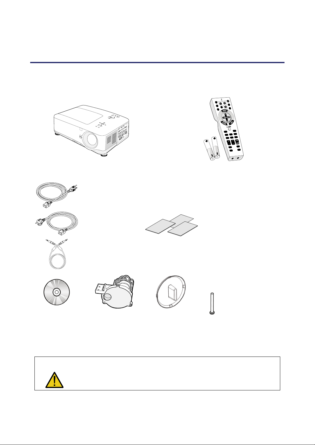
What’s in the Box?
Carefully unpack the projector and check that the following items are included:
NP4100/NP4100W Projector Remote Control (79TD5521)
CD-ROM
(This User’s manual)
(79TD6131)
North America
(AC 120V)
(79TD5701)
Europe
(AC 230V)
(79TD5711)
Remote Cable
10m/33ft
(79TD5481)
6 Segment Color
Wheel
(79TD5371)
Lens Hole Cap
(Installed)
(with Two AA alkaline batteries)
Quick setup guide
(79TD6151)
Important Information
(79TD6141)
For North America Only:
Registration Card
Limited Warranty
For customers in Europe: You
will find our current valid Guarantee Policy on our Web Site:
www.nec-display-solutions.com
Anti-Theft Screw for
lens x 1
(79TD5811)
Security Sticker
Contact your dealer immediately if any items are missing, appear damaged, or if the unit does not
work.
CAUTION
Avoid using the projector in dusty environments.
1
Page 17

1. Introduction
Introduction to the Projector
Features you’ll enjoy:
DLP projector with high resolution
Native WXGA support (NP4100W only)
A WXGA (1280 x 800) resolution provides wide screen display with an aspect ratio of
16:10.
High brightness
High brightness output of 6200 and 5500 lumens (NP4100 and NP4100W respectively) is achieved using the 4-segment color wheel.
Dual Lamp system
Two lamp system offers increased lamp life and energy savings along with redundancy.
Extensive optional lens with bayonet mount
Five types of optional lenses are available.
Powered Lens Shift, Zoom, and Focus offer installation flexibility
Powered Horizontal and Vertical lens shift provides the ability to project from off center
screen installations. Powered zoom and focus provide quick and easy adjustment.
Direct Power Off and Auto Power On
The projector has a feature called “Direct Power Off”. This feature allows the projector
to be turned off (even when projecting an image) using a power strip equipped with a
switch and a breaker.
Note:
Before using Direct Power Off, be sure to allow at least 20 minutes immediately
after turning on the projector and starting to display an image.
Also, the power cable can be removed immediately after turning off the projector.
Auto Start eliminates the need to always use the POWER (ON/STANDBY) button
on the remote control or projector cabinet.
A variety of input ports and a comprehensive array of system control interfaces
This projector supports input signals including BNC, DVI-D, analog RGB, component,
S-video, and composite.
3W+3W Stereo speaker
Built in 3W x 2 speakers are provided.
Preventing unauthorized use of the projector
Enhanced smart security settings for password protection, cabinet control panel lock to
help prevent unauthorized access, adjustments and theft deterrence.
Integrated RJ-45 connector for wired networking capability for property management.
Combination of BrilliantColor™ and 6-segment color wheel offers a more true color re-
production
2
Page 18

Part Names of the Projector
1. Introduction
Front-right view
ITEM LABEL DESCRIPTION SEE PAGE:
1.
2.
IR receiver Receiver for IR signal from remote control
Lamp cover Remove cover to replace lamp or color wheel
12
112
3.
4.
5.
6.
7.
8.
9.
10.
11.
12.
Lens control panel See Lens Controls
OSD control panel See OSD Controls and Status LEDS
I/O connector panel Connect various input devices
Intake vent Lamp cooling vent – do not obstruct
Speakers Built-in stereo speakers
Height adjuster Adjusts level of projector
Lens Remove lens hole cap before use
Lens release button
Anti-Theft Screw Prevent theft of the lens
Intake vent and front
filter
Important:
Grill openings on the projector allow for good air circulation, which keeps the projector lamp cool. Do not obstruct any of the grill openings.
Press the release button before removing the
lens
Keeps the front fan free of dust
– clean regularly for optimum performance
– do not obstruct
3
7
8
10
—
—
6, 45
—
—
—
108
Page 19

1. Introduction
Top View
ITEM LABEL DESCRIPTION SEE PAGE:
1.
2.
3.
4.
5.
6.
7.
Lens control panel See 3Lens Controls
Right-hand speaker Right-hand speaker
Lamp cover Remove cover to replace lamp or color wheel
Exhaust vent Exhaust vent – do not obstruct
OSD control panel See 3OSD Controls and Status LEDS
Rear intake vent Rear cooling intake – do not obstruct
Left intake vent Left-hand cooling intake – do not obstruct
7
—
112
—
8
—
—
4
Page 20

1. Introduction
Carrying the Projector
Always carry your projector by the handle.
Before moving or carrying the projector, disconnect the power cable and any other cables that may be attached to it.
When moving the projector or when the projector is not in use, cover the lens with the
lens cap.
To extend the projector handle, refer to the following guide.
1. Stand the projector on its end with the control panels at the bottom.
Note:
Stand the projector on its end by lifting the cabinet. Do not use the handle to place
the projector upright.
2. Lift the handle in the direction shown until it is fully extended.
5
Page 21

1. Introduction
Bottom view
ITEM LABEL DESCRIPTION SEE PAGE:
1.
2.
3.
4.
5.
6.
7.
Height adjusters Adjust projection height
Intake vent Color wheel cooling vent – do not obstruct
Front filter
Ceiling support holes
Security chain
opening
Rear filter
Side filter
With ceiling installation, use approved mounting hardware & M4 screws;
CAUTION
maximum depth of screw: 12 mm; distance from ceiling/ wall: 50/50 cm,
20/20 inch for proper ventilation; distance from fluorescent lamps: at least
50 cm front and back of then projector. For permanent installations, follow
local codes.
Keep the fan free of dust – clean regularly for
optimum performance
Contact your dealer for information on
mounting the projector on a ceiling
Attach anti-theft device –
see Using the Phy
Keep the fans free of dust –
clean regularly for optimum performance
sical Lock
45
—
108
—
61
108
6
Page 22

Top Features
1. Introduction
Lens Controls
ITEM LABEL DESCRIPTION SEE PAGE:
1.
ZOOM Increase/decrease projected image size
51
2.
3.
4.
5.
6.
UP CURSOR
RIGHT CURSOR
Move image left, right, up, or down
DOWN CURSOR
LEFT CURSOR
FOCUS Focus the projected image
7
51
Page 23

1. Introduction
OSD Controls and Status LEDS
ITEM LABEL DESCRIPTION SEE PAGE:
1.
2.
3.
4.
5.
6.
7.
MENU Open / Close the OSD
SELECT PAD Navigate and change settings in the OSD
RIGHT CURSOR/
VOLUME
INCREASE
EXIT Exit the On-Screen Display (OSD)
SOURCE
AUTO ADJUST Optimize image size, position, and resolution
LAMP 1
Increase volume
Change or select the input device
Green
See Indicator Messages
Flashing
62
62
47
63
40
46
118
8
Page 24

1. Introduction
ITEM LABEL DESCRIPTION SEE PAGE:
Green
8.
9.
10.
11.
12.
LAMP 2
Flashing
Green
POWER (LED)
STATUS (LED) Green
ON/STAND BY
ENTER Select or change settings in the OSD
Orange
Flashing
Turn the projector on or off
(main power switch must be turned on first)
See Indicator Messages
See Indicator Messages
Lamp ready you can safely turn
on or off the projector
118
117
117
10, 38
62
13.
LEFT
CURSOR/VOLUME
DECREASE
Decrease volume
9
47
Page 25

1. Introduction
Terminal Panel Features
ITEM LABEL DESCRIPTION SEE PAGE:
1.
2.
3.
4.
5.
6.
7.
8.
9.
COMPUTER 3 IN
AUDIO IN (3)
AUDIO OUT Audio loop-thru
MONITOR OUT Connect to a monitor
REMOTE 2 Connect the remote to the projector
AUDIO IN (2)
L/MONO, R
(COMPONENT)
PC CONTROL Installation control
REMOTE 1 For external control
Connect the DVI cable (not supplied) from a
computer
Connect the audio cable (not supplied) from
the input device
Connect the audio cable (not supplied) from
the input device
Connect an RCA audio cables (not supplied)
from the input device right and left channels
31
—
—
—
16
—
—
131
139
10
Page 26

1. Introduction
ITEM LABEL DESCRIPTION SEE PAGE:
When connected to the screen through a
commercially available cable, the screen de-
10.
SC TRIGGER
ploys automatically on start up of the
projector. The screen retracts when the projector is powered off (see notes below)
133
11.
12.
13.
14.
15.
16.
17.
18.
19.
S-VIDEO
POWER SWITCH Turn on/off the projector
AC IN Connect the supplied power cable
L/MONO, R
VIDEO IN
COMPONENT IN
(Y, Cb/Pb, Cr/Pr)
COMPUTER 2 IN
(R/Cr, G/Y, B/Cb,
H, V)
COMPUTER 1 IN
AUDIO IN (1)
Connect a commercially available S-video
cable from a video device
Connect RCA audio cables (not supplied)
from the input device right and left channels.
This audio jack is shared with S-Video input.
Connect a composite video cable (not supplied) from a video device to the yellow RCA
jack
Connect a component video enabled device
Connect RGBHV or Component signal from
computer or component video enabled device
Connect a VGA cable (not supplied) from a
computer
Connect the audio cable (not supplied) from
the input device
35
38, 48
37
—
35
34
31
31
—
20.
21.
LAN
SERVICE
Note:
To use this feature, you must turn on the Screen Trigger function on OSD.
Screen controllers are supplied and supported by screen manufacturers.
Do not use this jack for anything other than intended use. Connecting the wired
remote control to the Trigger mini jack causes damage to the remote control.
Connect a LAN cable (not supplied) from a
computer
Connect the USB cable (not supplied) from a
computer. For service personnel only.
11
103
—
Page 27

1. Introduction
Part Names of the Remote Control
The Remote Control unit supplied with the projector combines ergonomic design and utility
and includes features such as Volume and Zoom Control, Freeze Frame and a useful pointing tool in the form of a laser. Refer to the following diagram and table for button location and
functionality.
ITEM LABEL LABEL ITEM
1.
2.
3.
4.
5.
6.
7.
8.
9.
10.
11.
12.
13.
14.
15.
16.
17.
Remote jack Exit button
Laser pointer Laser button
Infrared transmitter L-Click button
LED R-Click button
Power OFF button* Focus/ Zoom button
Power ON button** Freeze button
Computer 1 button Lens shift button
Computer 2 button Aspect button
Video button Lamp mode button
Viewer button
(The VIEWER and
PAGE buttons will
work with the other
models, which have a
Viewer function.
NP4100/NP4100W
does not have this
function).
Component button Volume buttons
Computer 3 button
S-Video button
LAN button
(Not available on
NP4100/NP4100W)
Menu button Keystone button
Select ▲▼◄►
button
Enter button
18.
19.
20.
21.
22.
23.
24.
25.
26.
Auto ADJ. button
27.
28.
Magnify button
(Not available on
NP4100W)
Page Up/Down buttons
(The VIEWER and
PAGE buttons will
work with the other
models, which have a
Viewer function.
NP4100/NP4100W
does not have this function).
Picture button
29.
30.
31.
32.
PIC-Mute button
Help button
33.
34.
12
Page 28

1. Introduction
Important:
1. Avoid using the projector with bright fluorescent lighting turned on. Certain high-
frequency fluorescent lights can disrupt remote control operation.
2. Be sure nothing obstructs the path between the remote control and the projector. If the path between remote and projector is obstructed, you can bounce the
remote signal off certain reflective surfaces such as projector screens.
3. The buttons and keys on the projector have the same functions as the corresponding buttons on the remote control. This user’s manual describes the
functions based on the remote control.
Note:
*To turn off the projector, press the Power OFF button twice.
**To turn on the projector, press and hold the Power On button for a minimum of
two seconds.
13
Page 29

1. Introduction
Battery Installation
The Remote Control unit included with the projector does not contain batteries, though
batteries are supplied as part of the complete package. To insert (or replace) the batteries, refer to the following guide.
Remove the battery compartment
1.
cover by squeezing the locking
catch (A) and sliding the cover in
the direction of the arrow (B).
Insert the supplied batteries tak-
2.
ing note of the polarity (+/-) as
shown.
Replace the cover locator (A),
3.
and then click locking catch into
place (B).
14
Page 30

1. Introduction
Operating Range for Wireless Remote Control
The infrared signal operates by line-of-sight up to a distance of about 22 feet (7m) and
within a 60-degree angle of the remote sensor on the projector cabinet.
The projector will not respond if there are objects between the remote control and the
sensor, or if strong light falls on the sensor. Weak batteries will also prevent the remote
control from properly operating the projector.
Remote Control Precautions
The following precautions ensure that the remote operates correctly and safely.
Handle the remote control carefully.
If the remote control gets wet, wipe it dry immediately.
Avoid excessive heat and humidity.
Do not heat, take apart, or throw batteries into fire.
For extended periods of inactivity, remove the batteries.
Ensure that the batteries' polarity (+/–) aligned correctly.
Do not use new and old batteries together, or different types of batteries to-
gether.
Dispose of used batteries according to local regulations.
15
Page 31

1. Introduction
Using the Remote Control in Wired Operation
Connect the supplied remote cable to the REMOTE2 jack on the projector (see Terminal Panel Features on page 10) an
control (see item 1, Part Names of the Remote Control on page 12).
Note:
Connecting the remote cable to the REMOTE2 jack on the terminal panel will
make the wireless operation unavailable.
d the other end to the remote jack on the remote
16
Page 32

2. Installation and Connections
Setting Up the Screen and the Projector
This section briefly describes how to set up your projector and how to connect video and
audio sources.
Your projector is simple to set up and use. But before you get started, you must first:
• Set up a screen and the projector.
• Connect your computer or video equipment to the projector.
See Making Connections on pages 31, 32, 33, 34, and 35.
• Connect the supplied power cable.
See Connecting the Supplied Power Cable on page 37.
Note:
Ensure that the power cable and any other cables are disconnected before moving the projector. When moving the projector or when it is not in use, cover the
lens with the lens cap.
17
Page 33

2. Installation and Connections
Selecting a Location
Locating the projector correctly ensures optimum performance and a longer parts life.
Take note of the following when setting up the projector:
• The projector table or stand should be level and sturdy.
• Position the projector so that it is perpendicular to the screen.
• Ensure cables do not cause a trip hazard.
18
Page 34

2. Installation and Connections
Installing or Removing the Optional Lens
CAUTION:
• Do not shake or place excessive pressure on the projector or the lens compo-
nents as the projector and lens components contain precision parts.
• When shipping the projector with the optional lens, remove the optional lens
before shipping the projector. The lens and the lens shift mechanism may encounter damage caused by improper handling during transportation.
• Before removing or installing the lens, be sure to turn off the projector, wait
until the cooling fans stop, and turn off the main power switch.
• Do not touch the lens surface when removing or installing the lens.
• Keep fingerprints, dust or oil off the lens surface. Do not scratch the lens sur-
face.
• Work on a level surface with a soft cloth under it to avoid scratching.
• If you remove and store the lens, attach the lens cap to the projector to keep
off dust and dirt.
Removing the Existing Lens From the Projector
Pull out the lens cap.
1.
19
Page 35

2. Installation and Connections
Push the LENS
2.
RELEASE button all the
way in and rotate the lens
counterclockwise.
The existing lens will be
disengaged.
Note:
If the lens cannot be
removed even by using
the LENS RELEASE
button, the anti-theft
screw for lens may be
in use to secure the
lens. If that is the case,
remove the anti-theft
screw first.
Pull out the existing lens
3.
slowly.
CAUTION:
When Installing the lens into the projector, be sure to remove the lens cap
from the back of the optional lens before installing the optional lens into the
projector. Failure to do so will cause damage to the projector.
20
Page 36

Installing the New Lens
Insert the lens with the
1.
arrow mark on top.
Rotate the lens clock-
2.
wise until you feel it
click into place.
2. Installation and Connections
Installing the New Lens Using the anti-theft screw
Using the anti-theft
screw to prevent theft of
the lens.
Tighten the supplied
anti-theft screw on the
front bottom.
AAnnttii--tthheefftt ssccrreeww
21
Page 37

2. Installation and Connections
Throw Distance and Screen Size
Example of NP08ZL:
The further your projector is from the screen or wall, the larger the image. The minimum size
the image can be is approximately 40 inches (1 m) measured diagonally when the projector is
roughly 65 inches (1.7 m) from the wall or screen. The largest the image can be is 500 inches
(12.7 m) when the projector is about 843 inches (21.4 m) from the wall or screen.
Note:
The following image represents the NP4100 model. For the corresponding
NP4100W values, see NP4100W Throw Distance and Screen Size Values on
page 24.
22
Page 38

2. Installation and Connections
NP4100 Throw Distance and Screen Size Values
Screen Size NP06FL NP07ZL NP08ZL
Diagonal Width (C) Height (B)
[inches] [m] [inches] [m] [inches] [m] [inches] [m] [inches] [m] [inches] [m]
40 1.02 32 0.81 24 0.61 41.7 - 56.8 1.06 - 1.44 55.8 - 74.4 1.42 - 1.89
50 1.27 40 1.02 30 0.76 30.7 0.78 52.6 - 71.5 1.34 - 1.82 70.4 - 93.7 1.79 - 2.38
60 1.52 48 1.22 36 0.91 37.1 0.94 63.5 - 86.1 1.61 - 2.19 85.0 - 112.9 2.16 - 2.87
67 1.70 54 1.36 40 1.02 41.6 1.06 71.1 - 96.4 1.81 - 2.45 95.2 - 126.4 2.42 - 3.21
72 1.83 58 1.46 43 1.10 44.9 1.14 76.6 - 103.7 1.94 - 2.63 102.5 - 136.0 2.60 - 3.45
80 2.03 64 1.63 48 1.22 50.0 1.27 85.3 - 115.4 2.17 - 2.93 114.1 - 151.3 2.90 - 3.84
84 2.13 67 1.71 50 1.28 52.6 1.34 89.6 - 121.3 2.28 - 3.08 120.0 - 159.0 3.05 - 4.04
90 2.29 72 1.83 54 1.37 56.5 1.44 96.2 - 130.1 2.44 - 3.30 128.7 - 170.6 3.27 - 4.33
100 2.54 80 2.03 60 1.52 63.0 1.60 107.0 - 144.7 2.72 - 3.68 143.3 - 189.8 3.64 - 4.82
120 3.05 96 2.44 72 1.83 75.9 1.93 128.8 - 174.0 3.27 - 4.42 172.5 - 228.2 4.38 - 5.80
150 3.81 120 3.05 90 2.29 95.3 2.42 161.5 - 218.0 4.10 - 5.54 216.2 - 285.9 5.49 - 7.26
180 4.57 144 3.66 108 2.74 114.6 2.91 194.1 - 261.9 4.93 - 6.65 260.0 - 343.6 6.60 - 8.73
200 5.08 160 4.06 120 3.05 127.6 3.24 215.9 - 291.2 5.48 - 7.40 289.1 - 382.0 7.34 - 9.70
210 5.33 168 4.27 126 3.20 226.8 - 305.9 5.76 - 7.77 303.7 - 401.3 7.71 - 10.19
240 6.10 192 4.88 144 3.66 259.5 - 349.8 6.59 - 8.89 347.5 - 458.9 8.83 - 11.66
261 6.63 209 5.30 157 3.98 282.3 - 380.6 7.17 - 9.67 378.1 - 499.3 9.60 - 12.68
270 6.86 216 5.49 162 4.11 292.1 - 393.8 7.42 - 10.00 391.2 - 516.6 9.94 - 13.12
300 7.62 240 6.10 180 4.57 324.8 - 437.7 8.25 - 11.12 435.0 - 574.3 11.05 - 14.59
350 8.89 280 7.11 210 5.33 379.2 - 511.0 9.63 - 12.98 507.9 - 670.4 12.90 - 17.03
400 10.16 320 8.13 240 6.10 433.7 - 584.3 11.02 - 14.84 580.8 - 766.5 14.75 - 19.47
450 11.43 360 9.14 270 6.86 488.1 - 657.5 12.40 - 16.70 653.7 - 862.6 16.60 - 21.91
500 12.70 400 10.16 300 7.62 542.6 - 730.8 13.78 - 18.56 726.6 - 958.7 18.46 - 24.35
Screen Size NP09ZL NP10ZL
Diagonal Width (C) Height (B)
[inches] [m] [inches] [m] [inches] [m] [inches] [m] [inches] [m]
40 1.02 32 0.81 24 0.61 69.4 - 142.3 1.76 - 3.61 139.2 - 266.9 3.54 - 6.78
50 1.27 40 1.02 30 0.76 87.8 - 178.9 2.23 - 4.54 175.3 - 335.0 4.45 - 8.51
60 1.52 48 1.22 36 0.91 106.2 - 215.5 2.70 - 5.47 211.5 - 403.1 5.37 - 10.24
67 1.70 54 1.36 40 1.02 119.0 - 241.2 3.02 - 6.13 236.8 - 450.8 6.01 - 11.45
72 1.83 58 1.46 43 1.10 128.2 - 259.5 3.26 - 6.59 254.8 - 484.9 6.47 - 12.32
80 2.03 64 1.63 48 1.22 142.9 - 288.8 3.63 - 7.34 283.7 - 539.4 7.21 - 13.70
84 2.13 67 1.71 50 1.28 150.3 - 303.5 3.82 - 7.71 298.2 - 566.6 7.57 - 14.39
90 2.29 72 1.83 54 1.37 161.3 - 325.4 4.10 - 8.27 319.9 - 607.5 8.12 - 15.43
100 2.54 80 2.03 60 1.52 179.7 - 362.1 4.56 - 9.20 356.0 - 675.6 9.04 - 17.16
120 3.05 96 2.44 72 1.83 216.4 - 435.3 5.50 - 11.06 428.3 - 811.8 10.88 - 20.62
150 3.81 120 3.05 90 2.29 271.6 - 545.2 6.90 - 13.85 536.6 -
180 4.57 144 3.66 108 2.74 326.7 - 655.1 8.30 - 16.64 645.0 -
200 5.08 160 4.06 120 3.05 363.5 - 728.3 9.23 - 18.50 717.3 -
210 5.33 168 4.27 126 3.20 381.9 - 765.0 9.70 - 19.43 753.4 -
240 6.10 192 4.88 144 3.66 437.0 - 874.9 11.10 - 22.22 861.8 -
261 6.63 209 5.30 157 3.98 475.6 - 951.8 12.08 - 24.18 937.7 -
270 6.86 216 5.49 162 4.11 492.2 - 984.7 12.50 - 25.01 970.2 -
300 7.62 240 6.10 180 4.57 547.3 -
350 8.89 280 7.11 210 5.33 639.2 -
400 10.16 320 8.13 240 6.10 731.1 -
450 11.43 360 9.14 270 6.86 823.0 -
500 12.70 400 10.16 300 7.62 914.9 -
1094.6
13.90 - 27.80
1277.8
16.24 - 32.46
1460.9
18.57 - 37.11
1644.0
20.90 - 41.76
1827.2
23.24 - 46.41
Distance (A)
Distance (A)
1078.6
1259.2
1439.9
1620.5
1801.2
1016.1
13.63 - 25.81
1220.5
16.38 - 31.00
1356.7
18.22 - 34.46
1424.8
19.14 - 36.19
1629.1
21.89 - 41.38
1772.2
23.82 - 45.01
1833.5
24.64 - 46.57
-
2037.8
27.40 - 51.76
-
2378.3
31.98 - 60.41
-
2718.9
36.57 - 69.06
-
3059.4
41.16 - 77.71
-
3400.0
45.75 - 86.36
23
Page 39

2. Installation and Connections
NP4100W Throw Distance and Screen Size Values
Screen Size NP06FL NP07ZL NP08ZL
Diagonal Width (C) Height (B)
[inches] [m] [inches] [m] [inches] [m] [inches] [m] [inches] [m] [inches] [m]
40 1.02 34 0.86 21 0.54
50 1.27 42 1.08 26 0.67 33.1 0.84 56.5 -76.8 1.44 -1.95 75.8 - 100.8 1.93 - 2.56
60 1.52 51 1.29 32 0.81 40.0 1.02 68.2 -92.5 1.73 -2.35 91.5 - 121.4 2.32 - 3.08
67 1.70 57 1.44 36 0.90 44.9 1.14 76.4 -103.6 1.94 -2.63 102.4 - 135.9 2.60 - 3.45
72 1.83 61 1.55 38 0.97 48.3 1.23 82.3 -111.4 2.09 -2.83 110.2 - 146.2 2.80 - 3.71
80 2.03 68 1.72 42 1.08 53.9 1.37 91.6 -124.0 2.33 -3.15 122.8 - 162.7 3.12 - 4.13
84 2.13 71 1.81 45 1.13 56.6 1.44 96.3 -130.3 2.45 -3.31 129.0 - 171.0 3.28 - 4.34
90 2.29 76 1.94 48 1.21 60.8 1.54 103.3 -139.7 2.62 -3.55 138.4 - 183.4 3.52 - 4.66
100 2.54 85 2.15 53 1.35 67.7 1.72 115.0 -155.4 2.92 -3.95 154.0 - 204.0 3.91 - 5.18
120 3.05 102 2.58 64 1.62 81.6 2.07 138.4 -186.9 3.52 -4.75 185.3 - 245.3 4.71 - 6.23
150 3.81 127 3.23 79 2.02 102.4 2.60 173.5 -234.1 4.41 -5.95 232.2 - 307.2 5.90 - 7.80
180 4.57 153 3.88 95 2.42 123.1 3.13 208.6 -281.3 5.30 -7.14 279.2 - 369.2 7.09 - 9.38
200 5.08 170 4.31 106 2.69 137.0 3.48 232.0 -312.7 5.89 -7.94 310.4 - 410.5 7.88 - 10.43
210 5.33 178 4.52 111 2.83
240 6.10 204 5.17 127 3.23
261 6.63 221 5.62 138 3.51
270 6.86 229 5.82 143 3.63
300 7.62 254 6.46 159 4.04
350 8.89 297 7.54 185 4.71
400 10.16 339 8.62 212 5.38
450 11.43 382 9.69 238 6.06
500 12.70 424 10.77 265 6.73
44.8 -61.1 1.14 -1.55 60.2 - 80.1 1.53 - 2.04
243.7 -328.4 6.19 -8.34 326.1 - 431.1 8.28 - 10.95
278.8 -375.6 7.08 -9.54 373.0 - 493.0 9.47 - 12.52
303.3 -408.6 7.70 -10.38 405.8 - 536.4 10.31 - 13.62
313.9 -422.8 7.97 -10.74 419.9 - 555.0 10.67 - 14.10
349.0 -470.0 8.86 -11.94 466.8 - 616.9 11.86 - 15.67
407.5 -548.6 10.35 -13.93 545.0 - 720.1 13.84 - 18.29
465.9 -627.2 11.83 -15.93 623.2 - 823.4 15.83 - 20.91
524.4 -705.8 13.32 -17.93 701.4 - 926.6 17.82 - 23.54
582.9 -784.5 14.81 -19.93 779.6 - 1029.8
Screen Size NP09ZL NP10ZL
Diagonal Width (C) Height (B)
[inches] [m] [inches] [m] [inches] [m] [inches] [m] [inches] [m]
40 1.02 34 0.86 21 0.54 74.8 -153.2 1.90 -3.89 149.9 - 286.5 3.81 - 7.28
50 1.27 42 1.08 26 0.67 94.6 -192.5 2.40 -4.89 188.8 - 359.4 4.79 - 9.13
60 1.52 51 1.29 32 0.81 114.3 -231.9 2.90 -5.89 227.6 - 432.4 5.78 - 10.98
67 1.70 57 1.44 36 0.90 128.1 -259.4 3.25 -6.59 254.8 - 483.5 6.47 - 12.28
72 1.83 61 1.55 38 0.97 138.0 -279.1 3.51 -7.09 274.2 - 520.0 6.97 - 13.21
80 2.03 68 1.72 42 1.08 153.8 -310.6 3.91 -7.89 305.3 - 578.3 7.75 - 14.69
84 2.13 71 1.81 45 1.13 161.7 -326.3 4.11 -8.29 320.8 - 607.5 8.15 - 15.43
90 2.29 76 1.94 48 1.21 173.6 -349.9 4.41 -8.89 344.1 - 651.3 8.74 - 16.54
100 2.54 85 2.15 53 1.35 193.3 -389.2 4.91 -9.89 383.0 - 724.2 9.73 - 18.40
120 3.05 102 2.58 64 1.62 232.8 -467.9 5.91 -11.89 460.6 - 870.2 11.70 - 22.10
150 3.81 127 3.23 79 2.02 292.0 -586.0 7.42 -14.88 577.2 - 1089.0 14.66 - 27.66
180 4.57 153 3.88 95 2.42 351.3 -704.0 8.92 -17.88 693.7 - 1307.9 17.62 - 33.22
200 5.08 170 4.31 106 2.69 390.7 -782.7 9.92 -19.88 771.3 - 1453.8 19.59 - 36.93
210 5.33 178 4.52 111 2.83 410.5 -822.0 10.43 -20.88 810.2 - 1526.8 20.58 - 38.78
240 6.10 204 5.17 127 3.23 469.7 -940.0 11.93 -23.88 926.7 - 1745.7 23.54 - 44.34
261 6.63 221 5.62 138 3.51 511.2 -1022.6 12.98 -25.98 1008.3 - 1898.9 25.61 - 48.23
270 6.86 229 5.82 143 3.63 529.0 -1058.1 13.44 -26.87 1043.2 - 1964.5 26.50 - 49.90
300 7.62 254 6.46 159 4.04 588.2 -1176.1 14.94 -29.87 1159.7 - 2183.4 29.46 - 55.46
350 8.89 297 7.54 185 4.71 686.9 -1372.8 17.45 -34.87 1353.9 - 2548.2 34.39 - 64.72
400 10.16 339 8.62 212 5.38 785.6 -1569.5 19.96 -39.87 1548.1 - 2913.0 39.32 - 73.99
450 11.43 382 9.69 238 6.06 884.4 -1766.2 22.46 -44.86 1742.3 - 3277.8 44.25 - 83.26
500 12.70 424 10.77 265 6.73 983.1 -1962.9 24.97-49.86 1936.5 - 3642.6 49.19 - 92.52
Distance (A)
19.80 - 26.16
Distance (A)
24
Page 40

2. Installation and Connections
For screen sizes between 40 inches and 500 inches not indicated in the tables on pages 23
and 24, use the formulas below for the throw distance:
THROW DISTANCE FOR NP4100
LENS [INCHES] [METERS]
NP06FL C × 0.808 - 1.654 C × 0.808 - 0.042
NP07ZL
NP08ZL
NP09ZL
NP10ZL
C × 1.361 - 1.85
through C × 1.831 - 1.811
C × 1.823 - 2.52
through C × 2.403 - 2.441
C × 2.298 - 4.134
through C × 4.579 - 4.213
C × 4.516 - 5.315
through C × 8.514 - 5.512
THROW DISTANCE FOR NP4100W
C × 1.361 - 0.047
through C × 1.831 - 0.046
C × 1.823 - 0.064
through C × 2.403 - 0.062
C × 2.298 - 0.105
through C × 4.579 - 0.107
C × 4.516 - 0.135
through C × 8.514 - 0.140
LENS [INCHES] [METERS]
NP06FL C × 0.817 - 1.535 C × 0.817 - 0.039
NP07ZL
NP08ZL
C × 1.379 - 1.969
through C × 1.854 - 1.811
C × 1.844 - 2.362
through C × 2.435 - 2.48
C × 1.379 - 0.050
through C × 1.854 - 0.046
C × 1.844 - 0.060
through C × 2.435 - 0.063
NP09ZL
NP10ZL
* “C” means the screen width.
C × 2.328 - 4.134
through C × 4.639 - 4.173
C × 4.580 - 5.433
through C × 8.604 - 5.354
C × 2.328 - 0.105
through C × 4.639 - 0.106
C × 4.580 - 0.138
through C × 8.604 - 0.136
25
Page 41

2. Installation and Connections
Ceiling installation must be done by a qualified professional. Contact your
NEC dealer for more information.
It is not recommended you install the projector yourself.
Only use the projector on a solid, level surface. Serious injury and damage can occur if the projector falls to the ground.
CAUTION
Do not use the projector in an environment where extreme temperature
occurs. The projector must be used at temperatures between 41 degrees
Fahrenheit (5 degrees Celsius) and 104 degrees Fahrenheit (40 degrees
Celsius).
Screen damage will occur if the projector is exposed to moisture, dust or
smoke.
Do not cover the vents on the projector. Proper ventilation is required to
dissipate heat. Damage to the projector will occur if the vents are covered.
26
Page 42

2. Installation and Connections
Replacing Color Wheel
The NP4100/NP4100W projector comes with a four-segment color wheel installed. An additional six-segment color wheel comes included. To replace the color wheel (located under the
lamp cover adjacent to lamp 1) refer to the following guide.
Note:
• Before replacing the color wheel, be sure to turn off the projector, wait until the
cooling fans stop, and turn off the main power switch.
• Wait until the lamp house and the color wheel cool off.
• Do not touch the disk of the color wheel. Doing so may scratch the disk or leave
fingerprints, causing the image quality to degrade.
• Heed the following information if you own two or more NP4100/NP4100W projectors:
When replacing or re-installing the color wheel, the original color wheel preinstalled or supplied as an accessory must go back to its original projector. Your
color wheel and projector color wheel cover are given an identification number. Be
sure to use the color wheel pre-installed or supplied with your projector to match
its identification number.
If you remove a color wheel from one NP4100/NP4100W projector and re-install it
into another NP4100/NP4100W projector, performance may be compromised.
• Be sure turn off the main power switch before replacing the color wheel. Failure
to do so may result in electrical shock or damage to the projector, and cause an irregular color of the projected image.
Loosen the captive
1.
screw (A) on the lamp
cover.
Remove the lamp cover
2.
by sliding in the direction of the arrow (B).
27
Page 43

2. Installation and Connections
Remove the screws
3.
from the color wheel
cover. Lift cover in the
direction shown and
place on a clean, dust
free surface.
Unscrew the retaining
4.
screws on the
four-segment color
wheel.
Note:
Improper (loose)
installation of the color
wheel prevents an
image from being
displayed.
Lift the unit in the direc-
5.
tion shown.
28
Page 44

Insert the six-segment
6.
color wheel
Secure the retaining
7.
screws as shown.
2. Installation and Connections
Replace the wheel cover
8.
as shown and secure the
screws to lock the cover
in place.
29
Page 45

2. Installation and Connections
.
Align the lamp cover
9.
(A) with the arrow mark
on the cabinet and slide
it into place.
Secure the captive
10
screw (B).
Storing Unused Color Wheel:
Keep the unused color wheel in the zipper bag in which the supplied 6-segment color wheel
was packaged.
This bag prevents dust from falling or collecting on the color wheel.
30
Page 46

Making Connections
2. Installation and Connections
Connecting Your PC or Macintosh Computer
Enabling the computer’s external display
Displaying an image on the notebook PC’s screen does not necessarily mean it outputs
a signal to the projector. When using a PC compatible laptop, a combination of function
keys will enable/disable the external display. Usually, the combination of the Fn-key
along with one of the 12 function keys gets the external display to come on or off. For
example, NEC laptops use Fn + F3, while Dell laptops use Fn + F8 key combinations to
toggle through external display selections.
To connect a PC or Macintosh computer to the projector, refer to the following guide.
1. Connect a computer to the projector through one of the three available input data
connections before turning on the PC or the projector. The best signal order
(from best to least suitable) is as follows:
Computer 3 (DVI-D connector with HDCP) in as shown below (see item 1,
Terminal Panel Features on page 10) is a digital signal and offers the best
connection to your computer.
Note:
The DVI (DIGITAL) connector (COMPUTER 3) accepts VGA
(640x480), SVGA (800x600), 1152x864, XGA (1024x768), SXGA
(1280x1024), and SXGA+(1400x1050) on the NP4100.
The DVI (DIGITAL) connector (COMPUTER 3) accepts VGA
(640x480), SVGA (800x600), 1152x864, XGA (1024x768), WXGA
(1280x800), SXGA (1280x1024), and WXGA+(1440x900@ up to
75Hz) on the NP4100W.
What is HDCP/HDCP technology?
HDCP is an acronym for High-bandwidth Digital Content Protection.
High bandwidth Digital Content Protection (HDCP) is a system for preventing illegal copying of video data sent over a Digital Visual Interface
(DVI).
If you are unable to view material via the DVI input, this does not necessarily mean the projector is not functioning properly. With the
implementation of HDCP, there may be cases in which certain content
is protected with HDCP and might not be displayed due to the decision/intention of the HDCP community (Digital Content Protection,
LLC).
Computer 2 in (see item 17, Terminal Panel Features on page 10) is an
analog signal; use a DSUB-15 cable-to-5BNC connection.
Computer 1 in (see item 18, Terminal Panel Features on page 10) an
analog signal that uses a standard RGB computer cable.
31
Page 47

2. Installation and Connections
2. Turn on the projector and select the chosen method of connection from the
source menu before turning on the PC (see Selecting a Source on page 40).
Turn on the PC.
3.
Note:
Failure to follow the above steps may not activate the digital output of the graphics
card resulting in no picture being displayed. Should this happen, restart your PC.
32
Page 48

2. Installation and Connections
Connecting an External Monitor
Connect an external monitor to the projector through RGB out connections as shown below (see item 4, Terminal Panel Features on page 10).
Note:
• Daisy chain connection is not possible.
• The MONITOR OUT connector will output no video signal (Digital signal) from
the COMPUTER 3 IN connector.
• When audio equipment is connected, the projector speaker is disabled.
33
Page 49

2. Installation and Connections
Connecting Your DVD Player with Component Output
To connect a DVD Player to the projector, refer to the following guide.
1. Connect the DVD Player to the projector as shown below before turning on the
Player or the projector.
2. Turn on the projector and select Component from the source menu before turning on the DVD Player (see Selecting a Source on page 40).
Turn on the DVD Player.
3.
Note:
Refer to your DVD player's owner's manual for more information about your DVD
player's video output requirements.
34
Page 50

2. Installation and Connections
Connecting Your VCR
To connect you VCR, refer to the following diagram.
Note:
Refer to your VCR owner’s manual for more information about your device’s requirements.
Images may not be displayed correctly when using an S-Video or Video connection to fast-forward or fast-rewind scanning.
The AUDIO IN RCA jack is shared between VIDEO IN and S-VIDEO IN.
35
Page 51

2. Installation and Connections
Connecting to a Network
The projector comes standard with a LAN port that provides network connectivity using a
LAN (RJ-45) cable. Network settings and Alert Mail settings for the projector can be adjusted
after connecting to your network through a LAN cable.
To use a LAN connection, open your web browser and assign the project an IP address on
the Network Settings screen. See page 91.
Example of LAN connection:
36
Page 52

2. Installation and Connections
Connecting the Supplied Power Cable
Refer to the following guidelines to connect the power supply to the projector.
1. Locate the projector correctly. See Selecting a Location on page 18.
Ensure Main Power switch is in the off position (O).
2.
3. Connect power cable to mains outlet.
4. Connect power cable to power inlet (AC IN) on the projector, see Terminal
Panel Features on page 10.
Note:
Make sure that the prongs are fully inserted into both the AC IN and the wall
outlet.
Note:
Ensure that the cables do not create a trip hazard.
37
Page 53

3. Projecting an Image (Basic Operation)
Turning on the Projector
Once the projector is correctly located and the power cable and other connections are in
place, it is important that the projector is powered on correctly in order to avoid damage to
components and unnecessary wear and tear. Refer to the following guide to power on the
projector.
Connect the power cable (A).
1.
Press the main power switch ( I )
to the on position as shown (B).
The power LED lights orange.
B
Press the On/Standby button
2.
once (see
Status LEDS on page 8). The
power LED lights green and the
internal cooling fan starts.
After approximately 10 seconds,
3.
the power LED flashes intermittently green.
The Lamp1 and Lamp2 LEDs
4.
light green and the Power LED
flashes more rapidly.
Once the power LED is lit
5.
solidly green, the projector is
ready for use.
3OSD Controls and
A
Note:
If any of the LEDs remain flashing or blink there may be a problem with the startup.
Please refer to the Troubleshooting section on page 117.
38
Page 54

3. Projecting an Image (Basic Operation)
Note on Startup Screen (Menu Language Select screen)
In the first instance of powering on the projector, the language menu is displayed to select the default language.
Select the required default language using the ▲ or ▼ buttons on the OSD menu panel
or the remote control unit and press Enter.
Note:
The language select screen only appears on the first instance of power on. All
subsequent operations assume the selected default language. To change the default see page 85.
39
Page 55

3. Projecting an Image (Basic Operation)
Selecting a Source
The Source can be selected from the projector's control panel or from the remote control unit.
Refer to the following guide to select Source.
Press Menu on the OSD
1.
control panel or on the
remote control unit to display the Main Menu.
Scroll to the Source menu
using ▲or▼ and press
Enter.
Note:
Return to the projected
image by pressing Exit
twice.
Select the required source
2.
using ▲or▼ and press
Enter.
Note:
If an XGA signal is not correctly recognized on NP4100W, set "WXGA Mode" to
Off (see page 99).
To check if the signal is recognized, go to "Source" under "Information" menu (see
page 3102).
40
Page 56

3. Projecting an Image (Basic Operation)
Adjusting the Picture Position and Picture Size
The Picture Position and Picture Size can be adjusted manually from the lens control panel or
from the remote control unit. Refer to the following guides to adjust Picture Position manually.
Adjusting Picture Position Manually
Press the Select keypad in
1.
any direction to bring up
the Lens Shift window.
Press the directional key
2.
as required to shift the
image. Releasing the
directional arrow will
re-center the cursor.
To alter the picture size,
3.
press Menu and select the
Adjust menu using
▲or▼. Press Enter to
open the Adjust menu.
Press ◄or► to select Im-
age Options followed by
▲or▼ to select the
Aspect Ratio. Press
Enter.
41
Page 57

3. Projecting an Image (Basic Operation)
The Aspect Ratio win-
4.
dow is displayed. Select
the desired picture size
using ▲or▼ and press
Enter.
Note:
The NP4100 and
NP4100W support different Aspect Ratio options
as shown.
When finished, press Exit
5.
to return to the projected
image.
NP4100 Aspect Ratio Options
NP4100W Aspect Ratio Options
42
Page 58

3. Projecting an Image (Basic Operation)
Lens Shift Adjustable Range
The adjustable range for lens shift is tabulated below and subject to the conditions listed.
Note:
The drawings below are applied to the lenses for NP07ZL, NP08ZL, NP09ZL, and
NP10ZL. The lens for NP06FL does not have a lens shift feature.
From the Remote Control Unit
Press the Lens Shift but-
1.
ton to bring up the Lens
Shift window.
43
Page 59

3. Projecting an Image (Basic Operation)
Press the directional keys
2.
as required to shift the
image. Releasing the directional arrow will recenter the cursor.
To alter the picture size,
3.
press the Aspect button to
display the Aspect Ratio
window.
Note:
The NP4100 and
NP4100W support different Aspect Ratio options
as shown.
Select the desired picture
4.
size using ▲or▼ and
press Enter.
When finished, press Exit
5.
to return to the projected
image.
NP4100 Aspect Ratio Options
NP4100W Aspect Ratio Options
44
Page 60

Adjusting the Projector Level
To raise the level of the projec-
1.
tor, twist the adjusters clockwise.
To lower the level of the projec-
2.
tor, lift the projector and twist
the adjusters counter clockwise.
3. Projecting an Image (Basic Operation)
45
Page 61

3. Projecting an Image (Basic Operation)
Optimizing an RGB Image Automatically
Adjusting the Image Using Auto Adjust
To optimize an RGB image automatically refer to the following guide.
Press the Auto ADJ. button on the Remote Unit (see item 27, Part Nam
mote Control on page 12) to optimize an RGB image automatically.
This adjustment may be necessary when you connect your computer for the first time.
es of the Re-
46
Page 62

3. Projecting an Image (Basic Operation)
Adjusting Volume Up and Down
The volume can be adjusted from the OSD Control Panel or with the Remote Control unit.
Refer to the following as a guide.
Press the Volume +/-
1.
buttons on the remote
control or the Select pad
left and right keys on the
OSD control panel. The
volume level is displayed
on screen.
Use the Volume +/- but-
2.
tons or the Select pad left
and right keys on the OSD
control panel to adjust the
level.
47
Page 63

3. Projecting an Image (Basic Operation)
Turning off the Projector
Once the projector is no longer required, it is important to shut it down correctly to avoid
damage or unnecessary wear and tear to the projector.
• Do not unplug the power cable from the wall outlet or projector when
the projector is powered on. Doing so can cause damage to the AC IN
CAUTION
Refer to the following guide to shut down the projector.
Press the On/Standby button
1.
once. The OSD displays the
message shown on the right.
connector of the projector and (or) the prong plug of the power cable.
To turn off the AC power supply when the projector is powered on,
use a power strip equipped with a switch and a breaker.
• Do not turn off the AC power supply within 10 seconds of making adjustment or setting changes and closing the menu. Doing so can
cause loss of adjustments and settings and return to default.
Press the On/Standby button
2.
again or Enter on the OSD control panel or the remote control
to verify power off.
The cooling fans keep operating
for a while (Cooling-off time).
The cooling fans stop operating
when the projector turns off
The projector enters Standby
3.
mode and the power LED lights
orange.
Press the Main Power switch to
4.
the off position (O) to turn off
the projector.
48
Page 64

3. Projecting an Image (Basic Operation)
About Direct Power Off
The projector has a feature called "Direct Power Off". This feature allows the projector to
be turned off (even when projecting an image) using a power strip equipped with a
switch and a breaker.
Note:
Before using Direct Power Off, be sure to allow at least 20 minutes immediately
after turning on the projector and starting to display an image.
After Use
Preparation: Make sure that the projector is turned off.
1. Unplug the power cable.
2. Disconnect any other cables.
3. Return the height adjusters to their original, minimum position.
4. Cover the lens with the lens cap.
49
Page 65

4. Convenient Features
Turning Off the Image and Sound
The projected image and sound can be turned off for short periods of time with the remote
control. This feature is useful for breaking up presentations or for other brief interruptions in
projections. To turn off the picture and image, refer to the following guide.
1. Press the PIC-MUTE button on the remote control once
(see Part Names of the Remote Control on page 12).
To resume projection, press the PIC-MUTE button once more.
2.
Note:
For extended periods of time it is recommended that the projector be powered off.
Freezing a Picture
The projected image can be frozen for short periods of time via the remote control. This feature is useful for capturing still images from movies or freezing an animation at a particular
point. To freeze the projected image, refer to the following guide.
1. Press the Freeze button on the remote control once
(see Part Names of the Remote Control on page 12).
The screen freezes.
2.
3. To resume, press the Freeze button once more.
Note:
For extended periods of time it is recommended that the projector be powered off.
50
Page 66

4. Convenient Features
Adjusting the Focus/Zoom Manually
The focus and zoom can be adjusted manually from the projector focus/zoom panel or from
the remote control unit. Refer to the following guides to adjust the focus and zoom manually.
Adjusting by Using the OSD Control Panel
Press the Focus or Zoom
1.
button on the projector
panel to display the
appropriate window.
Adjust the focus/zoom
2.
using the increase and
decrease buttons as
required.
Press Exit to return to the
3.
projected image.
51
Page 67

4. Convenient Features
Changing Lamp Mode
The projector has two lamp modes available, Normal and Eco. The Normal mode is used for
everyday standard projection, whereas the Eco mode is used for saving power and lamp life.
To change the Lamp Mode, refer to the following guides.
Changing Lamp Mode by Using the Projector's OSD Control Panel
Press Menu on the projector's
1.
OSD control panel to display the
Main Menu. Scroll to the Setup
menu using ▲or▼ and press
Enter.
Select the General tab using
2.
◄or► and select Lamp Mode
using ▲or▼. Press Enter.
From the Lamp Mode window,
3.
select Normal or Eco using
▲or▼. Select OK and press
Enter.
52
Page 68

Changing Lamp Mode by Using the Remote Control
Press the Lamp Mode button on
1.
the remote control to access the
Lamp Mode menu.
4. Convenient Features
From the Lamp Mode window,
2.
select Normal or Eco using
▲or▼. Move the cursor to OK
and press Enter.
Note:
When the projector is in Eco mode, brightness may be affected.
Normal Mode: 100% Brightness
Eco Mode: approx. 85% Brightness
53
Page 69

4. Convenient Features
Getting Information
Press the HELP button on the remote control to display the "Information" screen. Use ◄ or
► to select a tab.
54
Page 70

4. Convenient Features
Adjusting Position/Clock
The Position/Clock/Phase and Keystone Correction can be adjusted manually from the projector's control panel or from the remote control unit. Refer to the following guides to adjust
the Keystone Distortion manually.
Adjusting Position/Clock/Phase by Using the OSD Control Panel
Press the Menu button to
1.
display the Main menu.
Select the Adjust menu
using ▲or▼ and press
Enter to display the
Adjust menu.
From the Adjust menu,
2.
press ◄or► to select Image Options and scroll
using ▲or▼ to
Horizontal, Vertical,
Clock, or Phase.
Adjust the Horizontal,
3.
Vertical, Clock, or Phase
sliding bars using the select ▲▼◄► buttons.
Press Exit to return to the
4.
projected image.
55
Page 71

4. Convenient Features
Correcting Keystone by Using the Remote Control
IMPORTANT:
When adjusting the keystone, set the lens shift position to the following.
• Horizontal: the lens center
• Vertical: the bottom of the projected image is aligned with the lens
center line in height.
Press the Keystone button
1.
to display the Keystone
window.
Adjust the Horizontal and
2.
Vertical sliding bars using the select ▲▼◄►
buttons.
Adjust the slide bars until
3.
the screen trapezoid is a
regular shape (see
diagram).
Press Exit to return to the
4.
projected image.
Note:
Holding down the Keystone button 2 seconds resets the default keystone values.
56
Page 72

4. Convenient Features
ADJUSTMENT HORIZONTAL VERTICAL
Keystone Max. +/– 35° approx. Max. +/– 40° approx.
The following are conditions under which the maximum angle is achieved:
When the NP08ZL lens is used
When the lens shift position is set to the following.
Horizontal: the lens center
Vertical: the bottom of the projected image is aligned with the lens center line in
height.
If you adjust the lens shift:
Image is projected in Wide mode
Resolution is XGA (NP4100) / WXGA (NP4100W)
Note:
Higher resolution than XGA (NP4100) / WXGA (NP4100W) narrows the adjustable range.
Aspect Ratio ........... 4:3 (NP4100) / 16:10 (NP4100W)
Horizontal and Vertical are adjusted separately.
A combination of both adjustments narrows the adjustable range.
57
Page 73

4. Convenient Features
Preventing the Unauthorized Use of the Projector
The projector has an inbuilt security feature to lock the OSD control panels and deny remote
control operation. The security feature has no default keyword; in the first instance of enabling the security feature, the user must define a keyword.
Locking the Projector
To setup the security keyword, refer to the following guide.
Press Menu on the OSD control
1.
panel on the projector or remote
control to display the Main
Menu. Scroll to the Setup menu
using ▲or▼ and press Enter.
The Setup menu is displayed.
2.
Select the Installation tab using
◄or► and select Security using
▲or▼. Press Enter.
58
Page 74

You are prompted to enable the
3.
Security Function. Select OK
and press Enter.
Select On using the ▼ button.
The keyword window is dis-
4.
played. Enter a keyword between
4 and 10 characters using
▲▼◄►. Press Enter.
4. Convenient Features
Once a successful keyword is
5.
entered, a confirmation screen is
displayed. Enter the same
password as the previous step
and write it down for later
reference. Press Enter. A
security activation message is
displayed. Select Cancel to return to the Setup menu or select
OK to enable security.
59
Page 75

4. Convenient Features
Unlocking the Projector
To unlock the projector, refer to the following guide.
When the projector is locked,
1.
either by request during operation or at start up, the locked
message is displayed.
To unlock the projector, press
2.
Menu on the control panel or
remote control. The keyword
window is displayed. Enter the
previously defined keyword to
activate the projector.
60
Page 76

4. Convenient Features
Using the Physical Lock
For security and authorized usage, the projector comes with two types of security features,
the Kensington Lock and the Security Chain Lock.
Using the Kensington Lock
If you are concerned about security, attach the projector to a permanent object with the
Kensington slot and a security cable.
Note:
Contact your vendor for details on purchasing a suitable Kensington security cable. The security lock corresponds to Kensington’s MicroSaver Security System. If
you have any comment, contact: Kensington, 2853 Campus Drive, San Mateo,
CA94403, U.S.A. Tel: 800-535-4242, http://www.Kensington.com.
Using the Security Chain Lock
In addition to the password protection function and the Kensington lock, the Security
Chain Opening helps protect the NP4100/NP4100W from unauthorized use.
See the following picture.
61
 Loading...