

Page 1
NEC Display Solutions of America, Inc.
NP400/NP500/NP600 Installation Guide
Ceiling Mounted and Desktop Rev 1.0
Contents
Product Description, Lens Specs, Notes and Formulas Pg 1
Diagrams & Distance Charts
Cabinet Dimensions
Ceiling Mount Dimensions
Input Panel and Control Codes
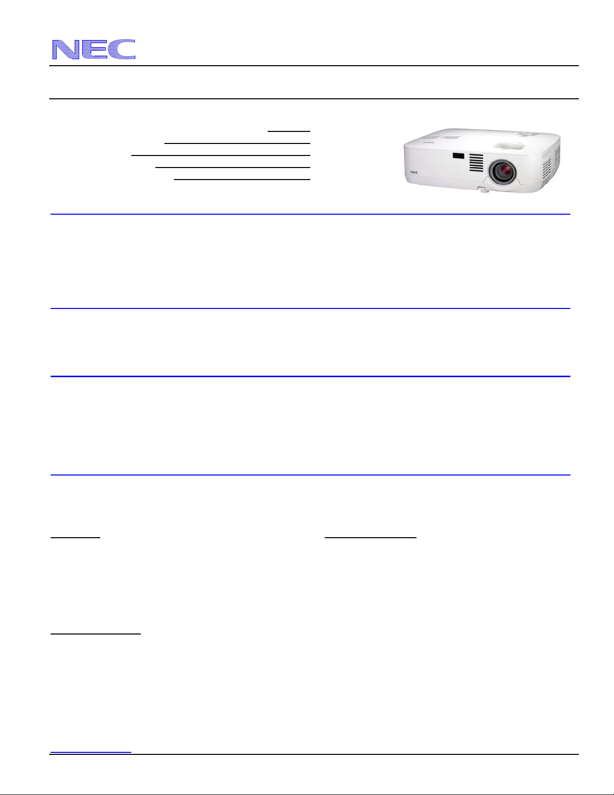
Product Description
Type: 3 panel LCD projector, Dimensions: 12.1” (W) x 4.3” (H) x 10.4” (D)
0.63” p-Si TFT w/MLA Weight: 6.6 lbs
Resolution: 1024 x 768 Brightness: NP400 - 2600 Lumens
Fan Noise: 35 dB / 29dB @ 1 meter NP500 - 3000 Lumens
NP600 - 3500 Lumens
Power Consumption: NP400/NP500 295W (max) BTU’s: 1007 BTU/hour
NP600 325W (max)
Lens Specifications
Throw Ratio: 1.5 – 1.8:1 (for 100” diagonal) Focal Length: 19.8mm – 23.7mm
Offset Angle: 8.0° - 9.6° (for 100” diagonal) F/#: 1.7 - 2.0
Screen Sizes: 21” - 300” diagonal (4:3) Manual Focus/Manual Zoom
Notes
For screen sizes not indicated on the projection tables, use the formulas below.
If the figures on the tables do not match the results of formulas, use the figures in the table.
• All calculations are based on a 4:3 aspect ratio.
• Distances are in inches, for millimeters multiply by 25.4.
• Distances may vary ±5%.
Formulas
The Projection Formulas use the image width for calculation. For proper projection placement, determine the image width
for the desired screen size. Use the Screen Formulas below to calculate all screen dimensions. Plug in the width for “W” in
the Projection Formulas.
Refer to the diagrams and charts for popular screen sizes on page 2:
Definitions: 4:3 Screen Formulas:
W = Image Width W = H x 4/3
H = Image Height (size) H = W x 3/4
B = Vertical distance between lens center and screen center Screen Diagonal = W x 5/4
C = Throw distance
D = Vertical distance between lens center and screen top
(screen bottom for desktop application)
Projection Formulas:
B = 0.258W
C (wide) = 1.5496W – 1.823
C (tele) = 1.8638W – 1.820
D = 0.118W
α (wide) = tan¯¹ (B/C(wide))
α (tele) = tan¯¹ (B/C(tele))
www.necdisplay.com NP400/NP500/NP600 Page 1 of 6
Pg 2
Pg 3-4
Pg 5
Pg 6
Page 2
d
inch
inch
NEC Display Solutions of America, Inc.
NP400/NP500/NP600 Installation Guide
Ceiling Mounted and Desktop Rev 1.0
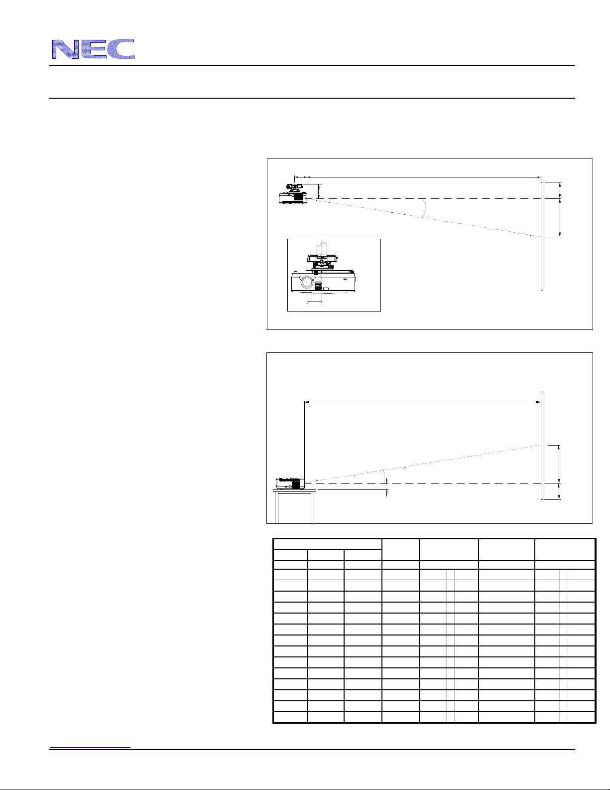
Diagrams and Distance Charts
The following shows the proper relative positions of the projector and screen. Refer to the table to determine the position of
installation.
Distances are in inches. For millimeters multiply by 25.4.
Ceiling Mounted
Desktop
Distance Chart for popular 4:3 screens
Note: For screen sizes not indicated on the projection
tables, use the formulas on page 1.
4.56"
5.17"
Lens Offset From
Mount Pipe
2.79
2.22"
Scr een Size (4:3)
Diagonal Width(W) Height (H)
inches inches inches inches
30 24 18 6 35 - 43 9.9 - 8.2
60 48 36 12 73 - 88 9.7 - 8.0
67 53.6 40.2 14 81 - 98 9.7 - 8.0
72 57.6 43.2 15 87 - 106 9.6 - 8.0
84 67.2 50.4 17 102 - 123 9.6 - 8.0
90 72 54 19 110 - 132 9.6 - 8.0
100 80 60 21 122 - 147 9.6 - 8.0
120 96 72 25 147 - 177 9.6 - 8.0
150 120 90 31 184 - 222 9.5 - 8.0
180 144 108 37 221 - 267 9.5 - 8.0
210 168 126 43 258 - 311 9.5 - 7.9
240 192 144 50 296 - 356 9.5 - 7.9
270 216 162 56 333 - 401 9.5 - 7.9
300 240 180 62 370 - 445 9.5 - 7.9
C
Throw Distance
C
Throw Distance
B
C
w ide - tele
es
D
-3
-6
-6
-7
-8
-8
-9
-11
-14
-17
-20
-23
-25
-28
Screen Top
Screen Ctr
Screen Ctr
Screen Bottom
α
w ide - tele
es
egrees
D
Lens Ctr
B
B
Lens Ctr
D
www.necdisplay.com NP400/NP500/NP600 Page 2 of 6
Page 3

NEC Display Solutions of America, Inc.
NP400/NP500/NP600 Installation Guide
Ceiling Mounted and Desktop Rev 1.0
Cabinet Dimensions
The following drawings show the cabinet dimensions.
Dimensions are in inches. For millimeters multiply by 25.4.
t
s
Lamp
u
a
h
x
E
e
k
a
Zoom Lever
Focus Lever
Lens Center
Exhaust
Lens Center
t
n
I
www.necdisplay.com NP400/NP500/NP600 Page 3 of 6
Page 4

NEC Display Solutions of America, Inc.
NP400/NP500/NP600 Installation Guide
Ceiling Mounted and Desktop Rev 1.0
Cabinet Dimensions (continued)
The following drawings show the cabinet dimensions.
Dimensions are in inches. For millimeters multiply by 25.4.
t
s
u
a
h
x
E
e
k
a
t
n
I
Exhaust
Lens Center
Intake
3 - M4*8 Max
for Ceiling Mount Kit
www.necdisplay.com NP400/NP500/NP600 Page 4 of 6
Page 5

NEC Display Solutions of America, Inc.
NP400/NP500/NP600 Installation Guide
Ceiling Mounted and Desktop Rev 1.0
Optional Ceiling Mount Dimensions (Model #: NP600CM)
The following drawings show the ceiling mount dimensions.
Dimensions are in inches. For millimeters multiply by 25.4.
www.necdisplay.com NP400/NP500/NP600 Page 5 of 6
Page 6

NEC Display Solutions of America, Inc.
NP400/NP500/NP600 Installation Guide
Ceiling Mounted and Desktop Rev 1.0
Input / Output Panel
PC Control Codes
Function Code Data
POWER ON 02H 00H 00H 00H 00H 02H
POWER OFF 02H 01H 00H 00H 00H 03H
INPUT SELECT COMPUTER 02H 03H 00H 00H 02H 01H 01H 09H
INPUT SELECT VIDEO 02H 03H 00H 00H 02H 01H 06H 0EH
INPUT SELECT S-VIDEO 02H 03H 00H 00H 02H 01H 0BH 13H
INPUT SELECT DVI (DIGITAL) 02H 03H 00H 00H 02H 01H 1AH 22H
INPUT SELECT DVI (ANALOG) 02H 03H 00H 00H 02H 01H 02H 0AH
PICTURE MUTE ON 02H 10H 00H 00H 00H 12H
PICTURE MUTE OFF 02H 11H 00H 00H 00H 13H
SOUND MUTE ON 02H 12H 00H 00H 00H 14H
SOUND MUTE OFF 02H 13H 00H 00H 00H 15H
PROJECTOR INFORMATION REQUEST 00H BFH 00H 00H 01H 02H C2H
ERROR STATUS REQUEST 00H 88H 00H 00H 00H 88H
INFORMATION REQUEST 03H 8AH 00H 00H 00H 8DH
Note: Contact your NEC rep for codes not listed.
Cable Connection
Communication Protocol:
Baud Rate: 38400 bps
Data Length: 8 bits
Parity: No Parity
Stop Bit: One Bit
X on/off: None
Communications: Full duplex
12
67 8
34
9
5
To TxD of PC
To RxD of PC
To GND of PC
PC Control Connector (D-Sub 9P
NOTE 1 : Pins 1, 4, 6, and 9 are used inside the projector.
NOTE 2: For long cable runs it is recommended to set communication speed within the projector to 9600 bps.
NOTE 3: Jumper “Request to Send” and “Clear to Send” together on both ends of the cable to simplify cable connection.
To RTS of PC
To CTS of PC
www.necdisplay.com NP400/NP500/NP600 Page 6 of 6
 Loading...