

Page 1
DLP Cinema® Projector
Installation Manual
DLP Cinema® Projector Head
NP-02HD
Light Module
NP-24LU01/NP-20LU01/NP-18LU01
Model No.
NP-02HD
NP-24LU01 / NP-20LU01 / NP-18LU01
Page 2

Introduction
DLP Cinema Projector Installation and Adjustment NEC Display Solutions, Ltd. Manual (This document) describes the procedures
to install, adjust and maintain the projector (NP-02HD). For safe and correct installation, adjustment and use of this projector, carefully read this document before location assessment and installation.
Refer to the operation manuals of the applicable products for basic operation and remarks of the projector. This document expects
the readers who have basic knowledge about projector installation. After reading, please keep this document under care of the
company which installed or adjusted the projector.
The product name used in this manual
In this manual, the device name is written as listed below. If the function has difference by devices, the product name is written in
the text.
• NP-02HD
• NP-90MS01/NP-90MS02
• Digital Cinema Communicator v2
..............................................Projector
......................Media block or IMB
...........DCC
2
Page 3
Important Information
Precautions
Please read this manual carefully before using your NP02HD and keep the manual handy for future reference. The
NP-02HD (projector unit) is called the “projector”, and the
NP-90MS01/NP-90MS02 (integrated media server) is called
the “media block” or “IMB” in this manual.
• DLP (Digital Light Processing), DLP Cinema, DLP Cinema
logo and CineLink are trademarks of Texas Instruments.
• CineLink is a trademark of Texas Instruments.
• Other product names and logos mentioned in the user’s
manual may be the trademarks or registered trademarks of
their respective holders.
• The display screens and illustrations shown in this manual
may differ slightly from the actual ones.
• GPL/LGPL Software Licenses
The product includes software licensed under GNU General
Public License (GPL), GNU Lesser General Public License
(LGPL), and others.
For more information on each software, see “readme.pdf”
inside the “about GPL&LGPL” folder on the supplied
CD-ROM.
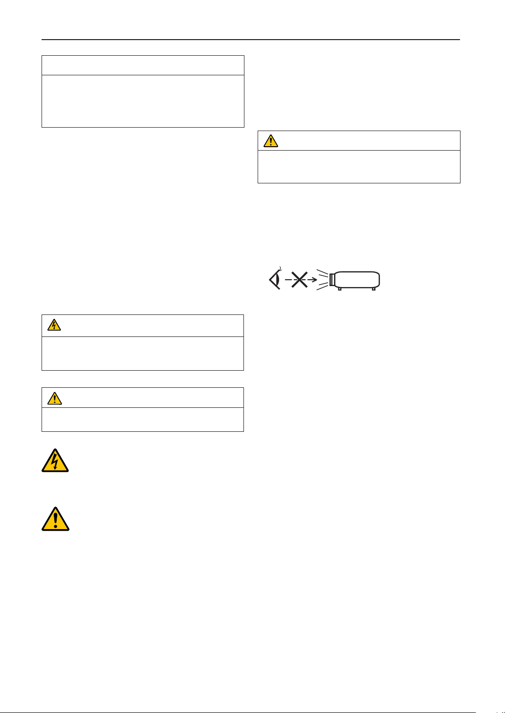
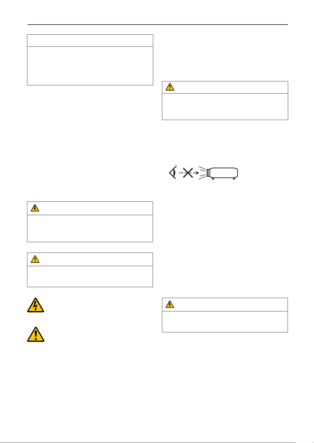
WARNING
TO REDUCE THE RISK OF FIRE OR ELECTRIC SHOCK,
DO NOT EXPOSE THIS APPLIANCE TO RAIN OR
MOISTURE.
CAUTION
TO PREVENT ELECTRIC SHOCK, DO NOT OPEN TOP
COVER. NO USER SERVICEABLE PARTS INSIDE.
This symbol warns the user that uninsulated voltage within the unit may have sufficient magnitude
to cause electric shock. Therefore, it is dangerous
to make any kind of contact with any part inside of
this unit.
This symbol alerts the user that important literature
concerning the operation and maintenance of this
unit has been included. Therefore, it should be
read carefully in order to avoid any problems.
Laser Safety Caution
This product is classified as Class 1 of IEC60825-1 Third edition
2014. This product is classified as RG3 of IEC62471-5 First
edition 2015. This product is classified as RG3 of IEC62471:2006
(for USA). Obey the laws and regulations of your country in relation to the installation and management of the device.
CAUTION
Use of controls or adjustments of procedures other than
those specified herein may lead to hazardous laser radiation
exposure.
• Hazardous optical radiation is emitted from this product, RG3
IEC 62471: 2006 (for USA).
• No direct exposure to the beam shall be permitted, RG3 IEC
62471-5: 2015.
• Do not look into the lens while the projector is on. Serious
damage to your eyes could result.
• Keep any items such as magnifying glass out of the light path
of the projector. The light being projected from the lens is
extensive, therefore any kind of abnormal objects that can
redirect light coming out of the lens, can cause unpredictable
outcome such as fire or injury to the eyes.
• When turning on the projector, ensure that nobody is facing
towards the lens in the path of the light emitted from the laser.
• This product can only be operated in theaters by specified
personnel. Customers should not operate this product.
DOC Compliance Notice (for Canada only)
This Class A digital apparatus meets all requirements of the
Canadian ICES-003 Standards.
Machine Noise Information Regulation - 3. GPSGV,
The highest sound pressure level is less than 70 dB (A) in accordance with EN ISO 7779.
3
Page 4
Important Information
WARNING
This equipment is compliant with Class A of CISPR 32. In a
residential environment this equipment may cause radio
interference.
CAUTION
• In order to reduce any interference with radio and television reception use a signal cable with ferrite core
attached. Use of signal cables without a ferrite core
attached may cause interference with radio and television
reception.
• This equipment has been tested and found to comply
with the limits for a Class A digital device, pursuant to Part
15 of the FCC Rules. These limits are designed to provide
reasonable protection against harmful interference when
the equipment is operated in a commercial environment.
This equipment generates, uses, and can radiate radio
frequency energy and, if not installed and used in accordance with the installation manual, may cause harmful
interference to radio communications. Operation of this
equipment in a residential area is likely to cause harmful
interference in which case the user will be required to
correct the interference at his own expense.
WARNING
THE END USER IS NOT ALLOWED TO OPEN OR MODIFY
THE PRODUCT.
NO USER SERVICEABLE PARTS.
MAINTENANCE AND SERVICE OF THE PRODUCT IS ONLY
TO BE HANDLED BY NEC AUTHORIZED TECHNICIANS.
Important Safeguards
These safety instructions are to ensure the long life of your projector and to prevent fire and shock. Please read them carefully
and heed all warnings.
Installation
1. Do not point the projection beam toward other people or
reflective objects.
2. Consult your dealer for information about transporting and
installing the projector. Do not attempt to transport and
install the projector yourself. The projector must be installed
by qualified technicians in order to ensure proper operation
and reduce the risk of bodily injury.
3. Place the projector on a flat, level surface in a dry area away
from dust and moisture. Do not put the projector on its side
when the laser is on. Doing so may cause damage to the
projector.
4. Do not place the projector in direct sunlight, near heaters or
heat radiating appliances.
5. Exposure to direct sunlight, smoke or steam could harm
internal components.
6. Handle your projector carefully. Dropping or jarring your
projector could damage internal components.
7. To carry the projector, a minimum of six persons are
required.
8. Do not hold the lens part with your hand. Otherwise the
projector may tumble or drop, causing personal injury.
9. Do not place heavy objects on top of the projector.
10. Turn off the projector, and disconnect the power cable
before moving the projector.
For C2 connection, turn off the projector, shut down the AC
power to the projector and the light using a circuit breaker.
Disconnect the cables between devices and the light
before moving the projector.
11. Do not install and store the projector in the below circumstances. Failure to do so may cause of malfunction.
• In powerful magnetic fields
• In corrosive gas environment
• Outdoors
12. If you wish to have the projector installed on the ceiling;
• Do not attempt to install the projector yourself.
• The projector must be installed by qualified technicians
in order to ensure proper operation and reduce the risk
of bodily injury.
• Install the breaker in a location that is easy to reach by
hand.
• To prevent ceiling collapse, the ceiling should be able to
support the combined weight (158 kg*
2
(150 kg*
) and lens (8 kg) for an extended period of time,
and the installation must be in accordance with any local
building codes.
1
*
When the light module NP-18LU01is installed, the
weight is about 149 kg.
2
*
When the light module NP-18LU01is installed, the
weight is about 141 kg.
• Please consult your dealer for more information.
Refer to “2-2-1. Installing the Projector on the Ceiling”
(page 55) for details on the attachment positions when
installing on the ceiling.
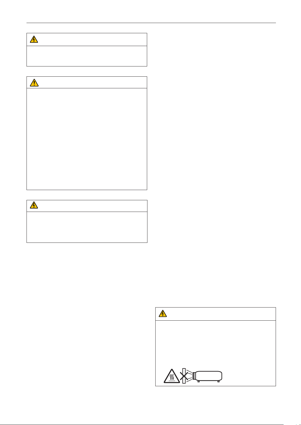
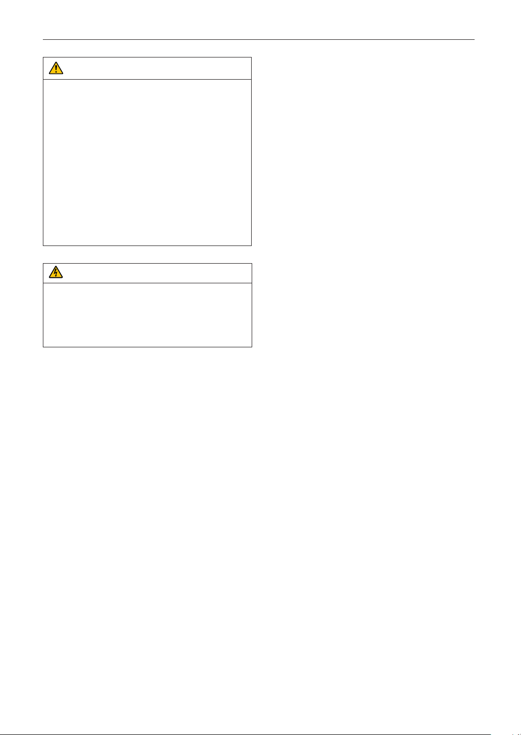
WARNING
1. Do not use the projector with the supplied lens cap or
equivalent while the projector is operating. This may
cause the lens cap to heat up and deform or melt.
2. Do not place any objects, which are easily affected by
heat, in front of the projector lens. Doing so could lead to
the object melting from the heat that is emitted from the
light output.
1
) of the projector
4
Page 5
Important Information
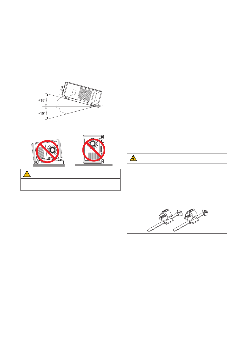
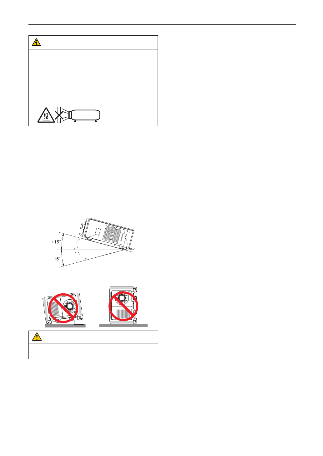
When using the projector tilted in the forward or backward
direction, use it in the range of (+15° to -15°) from horizontal. If
you tilt it outside of this range or tilt it to the left or right, it may
become damaged.
If the projector is tilted outside of this range when used tilted in
the forward or backward direction, “TiltDegreeOver” is displayed on the LCD screen. If this message appears, change the
installation of the projector so that the angle is within the given
range from horizontal.
When installed on a floor or a desktop
CAUTION
This equipment is not suitable for use in locations where
children are likely to be present
Power Supply
1. Consult your dealer for installing the power cable to the
projector. DO NOT install the power cable by yourself.
Doing so may cause a fire or electric shock.
The projector is so designed that it operates with the power
supply voltage described below.
For C1 connection
(When the AC power to the projector power supply and the
light power supply is provided by a single cable)
• AC 200V-240V single phase 50/60Hz
For C2 connection
(When the AC power to the projector power supply and the
light power supply is provided by separate cables)
• AC 100V-240V single phase 50/60Hz (projector power
supply)
• AC 200V-240V single phase 50/60Hz (light power
supply)
Ensure that your power supply fits this requirement before
attempting to use your projector.
2. The power cable is not included with the projector. Use a
power cable that meets the standards and power supply
voltage of the country where you are using the projector.
Refer to “2-3. Selecting the Power Cable for C2 Connection
(English)” for details.
3. Handle the power cable carefully. A damaged or frayed
power cable can cause electric shock or fire.
• Do not bend or tug the power cable excessively.
• Do not place the power cable under the projector, or any
heavy object.
• Do not cover the power cable with other soft materials
such as rugs.
• Do not heat the power cable.
4. Placing the power cable and the signal cable closely to
each other can cause beat noise. If this happens, keep the
two separated so that beat noise is not generated.
Beat noise is corruption of the picture often seen as a rolling
band moving through the image.
5. Do not touch the projector during a thunder storm. Doing
so can cause electrical shock or fire.
6. When installed on the ceiling, install the breaker in a location that is easy to reach by hand.
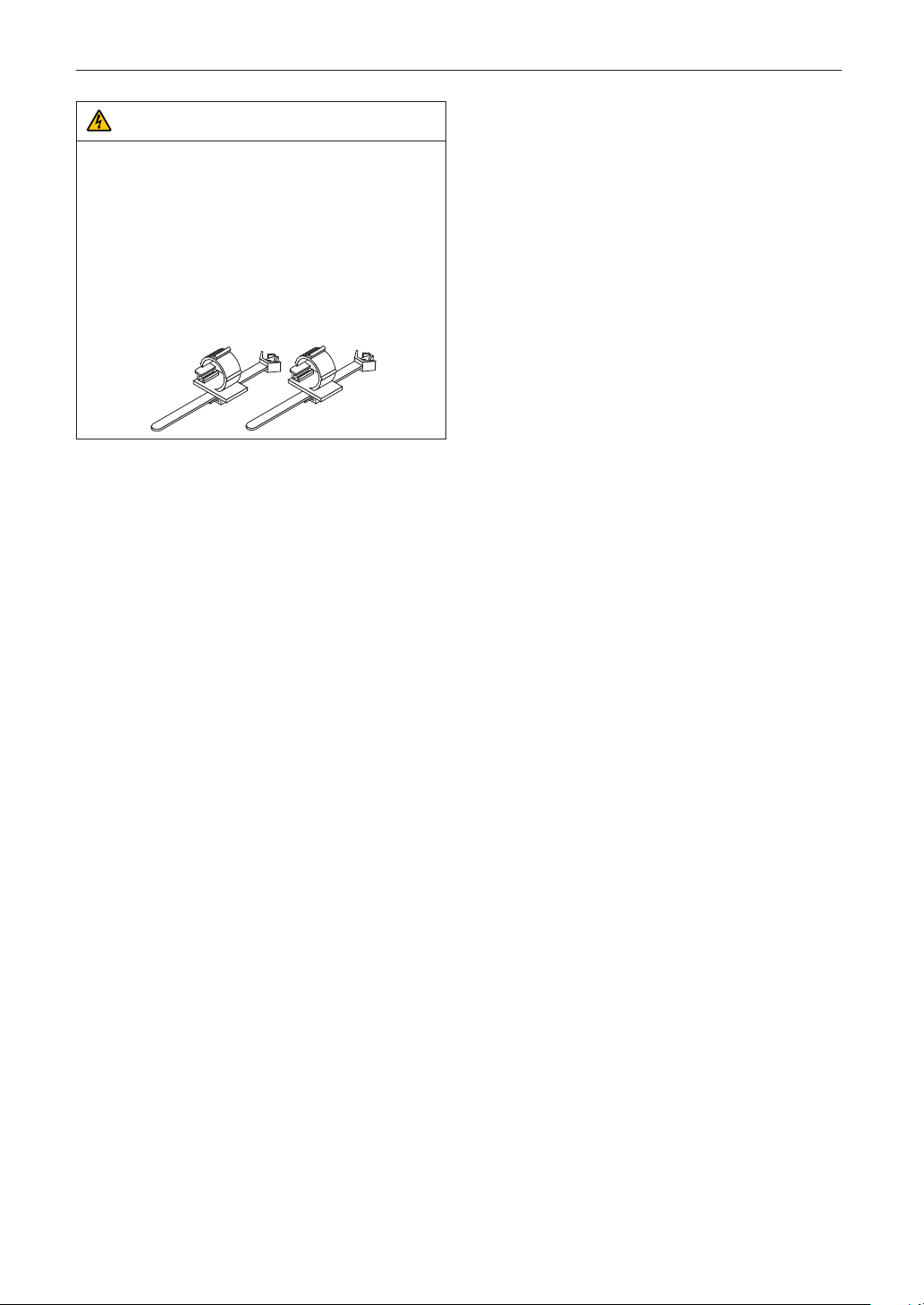
CAUTION
The power cable stopper (shown in below) is supplied with
this projector.
To prevent the power cable from coming loose, make sure
that all the prongs of the power cable are fully inserted into the
AC IN terminal of the projector before using the power cable
stopper to fix the power cable. A loose contact of the power
cable may cause a fire or electric shock. For using the power
cable stopper, refer to the user’s manual.
Fire and Shock Precautions
1. Ensure that there is sufficient ventilation and that vents are
unobstructed to prevent potentially dangerous concentrations of ozone and the build-up of heat inside your projector. Allow at least 24 inches (60 cm) of space between your
projector and a wall. In particular, clear a space of 26.7
inches (70 cm) or more in front of the air outlet on the rear
surface and 12 inches (30 cm) or more on the upper part of
the projecter body. (See page 39)
5
Page 6

Important Information
2. Prevent foreign objects such as paper clips and bits of
paper from falling into your projector. Do not attempt to
retrieve any objects that might fall into your projector. Do
not insert any metal objects such as a wire or screwdriver
into your projector. If something should fall into your projector, shut down the AC power to the projector immediately
and have the object removed by a qualified service
person.
For C2 connection, turn off the projector, shut down the AC
power to the projector and the light using a circuit breaker,
and contact your dealer/distributor.
3. Turn off the projector, shut down AC power by using a circuit breaker and contact qualified service personnel under
the following conditions. For C2 connection, turn off the
projector, shut down the AC power to the projector and the
light using a circuit breaker, and contact your dealer/distributor for a repair.
• When the power cable or plug is damaged or frayed.
• If liquid has been spilled into the projector, or if it has
been exposed to rain or water.
• If the projector does not operate normally when you follow
the instructions described in this user’s manual.
• If the projector has been dropped or the cabinet has
been damaged.
• If the projector exhibits a distinct change in performance,
indicating a need for service.
4. When using a LAN cable:
For safety, do not connect to the connector for peripheral
device wiring that might have excessive voltage.
Cleaning
1. Shut down AC power by using a circuit breaker before
cleaning.
For C2 connection, turn off the projector, shut down the AC
power to the projector and the light using a circuit breaker.
2. Clean the cabinet periodically with a cloth. If heavily soiled,
use a mild detergent. Never use strong detergents or solvents such as alcohol or thinner.
3. Use a blower or lens paper to clean the lens, and be careful
not to scratch or mar the lens.
4. Do not handle the projector and the power cable with wet
hands. Doing so can cause electrical shock or fire.
CAUTION
1. Do not shut down AC power to the projector under the
following conditions.
Doing so can damage the projector.
• While projecting images
• While cooling after the power is turned off.
(The STATUS indicator LED blinks in orange while the
fan is rotating, and “cooling...” is displayed on the LCD
screen. )
- When using the NP-90MS01/NP-90MS02: 100
seconds
• During IMB Operation (if the projector is not in standby
state)
2. Do not turn off the AC power for 90 seconds after the
laser is turned on and while the POWER indicator is blinking green. Doing so could cause premature laser failure.
3. Keep hands away from the lens mounting portion while
the lens shift is in operation. Failure to do so could result
in fingers being pinched between the cabinet and lens
cover.
4. When main body is damaged, cooling fluids may come
out of internal part. DO NOT touch and drink the cooling
fluid.
When the cooling fluids are swallowed or contacted with
your eyes, please consult with doctors immediately.
Caution on Carrying the Projector/Handling the Optional
Lens
When installing/removing a lens, shut down the AC power to
the projector.
When shipping the projector with the lens, remove the lens
before shipping the projector. Always attach the dust
cap to the lens whenever it is not mounted on the projector. The
lens and the lens shift mechanism may encounter damage
caused by improper handling during transportation.
6
Page 7

Handling the Battery
• Take care when handling the battery, as it could cause fire,
injury, or damage to surrounding objects.
- Do not short out, dismantle, or place batteries in a fire.
• Dispose of used batteries according to your local
regulations.
• There is a battery mounted on the electronic circuit board
within the main unit. When disposing of the main unit, do not
dismantle the device or remove the internal circuit board, and
contact the shop where you purchased the product or your
local government agency.
Peripheral Devices and Connecting Cables
Use shielded cables for the cables connecting the IMB with
peripheral devices (GPI, GPO, AES cables). If you use a nonshielded cable, there is a risk that radio interference may occur.
WARNING TO CALIFORNIA RESIDENTS:
Handling the cables supplied with this product will expose
you to lead, a chemical known to the State of California to
cause birth defects or other reproductive harm. WASH
HANDS AFTER HANDLING
Important Information
Light Module
1. A light module containing multiple laser diodes is included
in the product as the light source.
2. These laser diodes are sealed in the light module. No main-
tenance or service is required for the performance of the
light module.
3. End user is not allowed to replace the light module.
4. Contact qualified distributor for light module replacement
and further information.
7
Page 8

Important Information
Disposing of your used product
EU-wide legislation as implemented in each Member State requires that used electrical and electronic products carrying the mark (left) must be
disposed of separately from normal household
waste.
This includes projectors and their electrical accessories. When you dispose of such products,
please follow the guidance of your local authority
and/or ask the shop where you purchased the
product.
After collecting the used products, they are reused
and recycled in a proper way. This effort will help
us reduce the wastes as well as the negative
impact to the human health and the environment
at the minimum level.
The mark on the electrical and electronic products
only applies to the current European Union Member States.
For EU: The crossed-out wheeled bin implies that
used batteries should not be put to the general
household waste! There is a separate collection
system for used batteries, to allow proper treatment and recycling in accordance with legislation.
According the EU directive 2006/66/EC, the
battery can’t be disposed improperly. The bat-
tery shall be separated to collect by local
service.
For questions relating to unclear points or repairs
Contact your dealer or the following support branch for questions relating to unclear points, malfunctions and repairs of the
product.
In Europe
Company Name: NEC Display Solutions Europe GmbH
Address: Landshuter Allee 12-14, D-80637 Munichi, Germany
Telephone: +49 89 99699 0
Fax Line: +49 89 99699 500
Email Address: [email protected]
WEB Address: https://www.nec-display-solutions.com
In China
Company Name: NEC Solutions (China) Co., Ltd.
Address: Rm 1903, Shining Building, 35 Xueyuan Rd,
Haidian District Beijing 100191, P.R.C.
Telephone: +8610-4008-900-678
Email Address: [email protected]
In Hong Kong and Taiwan
Company Name: Strong Westrex, Inc.
Address: Room 4108 China Resources Building, No. 26
Harbour Road, Wanchai, Hong Kong
Telephone: +852 2827 8289
Fax Line: +852 2827 5993
Email Address: [email protected]
In South Korea
Company Name: Hyosung ITX Co., Ltd.
Address: 1F, Ire Building, 2, Yangpyeong-dong 4-ga,
Yeongdeungpo-gu, Seoul, Korea 150-967
Telephone: +82-2-2102-8591
Fax Line: +82-2-2102-8600
Email Address: [email protected]
WEB Address: http://www.hyosungitx.com
In Australia and New Zealand
Company Name: NEC Australia Pty Ltd
Address: 26 Rodborough Road Frenchs Forest NSW 2086
Telephone: 131 632 (from anywhere in Australia)
Email Address: [email protected]
WEB Address: http://www.nec.com.au
In Thailand, Singapore, Malaysia, Indonesia and
Philippines
Company Name: Goldenduck International Co., Ltd.
Address: 65 Soi Phutthamothon Sai 1, 21 Bangramad,
Talingchan, Bangkok, Thailand 10170
Telephone: +66-2887-8807
Fax Line: +66-2887-8808
Email Address: [email protected]
In North America
Company Name: NEC Display Solutions of America, Inc.
Address: 500 Park Boulevard, Suite 1100 Itasca, Illinois
60143, U.S.A.
Telephone: +1 800 836 0655
Fax Line: +1 800 356 2415
Email Address: [email protected]
WEB Address: https://www.necdisplay.com/
8
Page 9
Label Information
Label A
Important Information
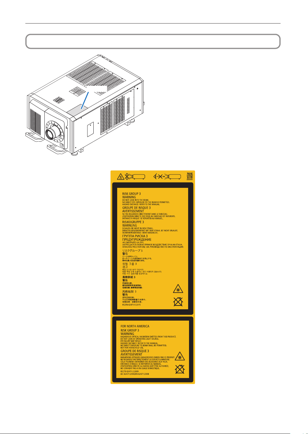
Label A: Lamp Warning Label
9
Page 10
Important Information
Label C
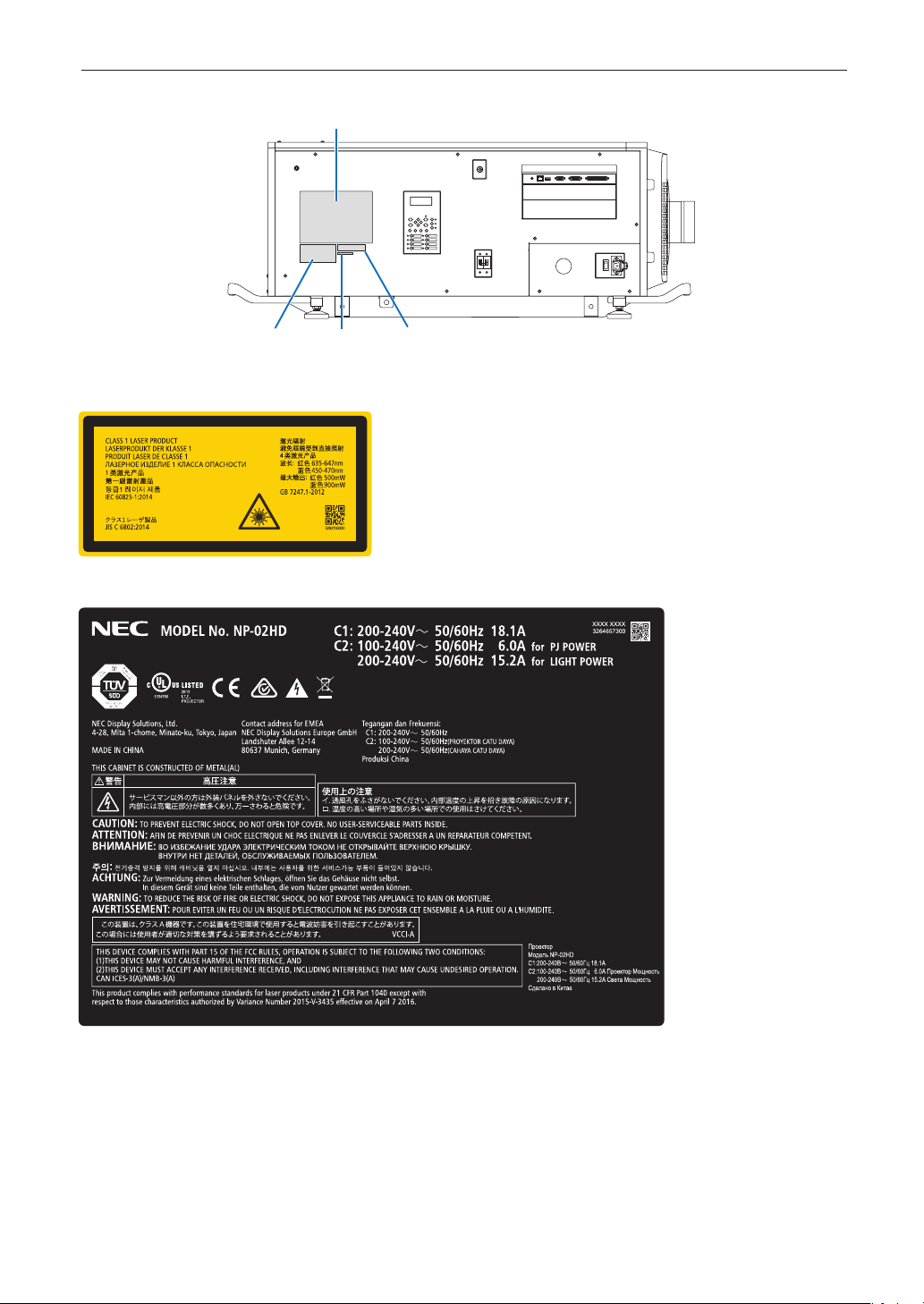
• Label B
Laser Explanatory Label
• Label C
Label B
Label E
Label D
10
Page 11

• Label D
• Label E
Important Information
11
Page 12
Important Information
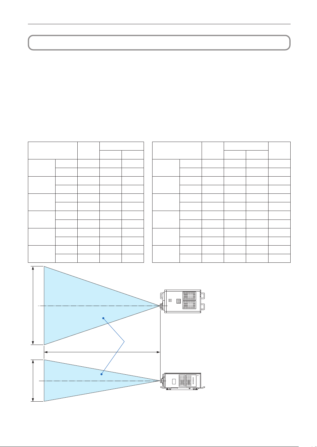
Radiation Range of Emitted Light by the Projector (HD: Hazard Distance)
• The below table describes the radiation range of emitted light by the projector that is classified as Risk Group 3 (RG3) of
IEC62471-5 First edition 2015.
• The below table describes the radiation range of emitted light by the projector that is classified as Risk Group 3 (RG3) of
IEC62471:2006.(for USA).
• Please keep within bounds for installing the projector.
Install a barrier for preventing human eyes from entering the RG3 area.For the barrier installation position, keep horizontal safety
zone over 1.5m from the RG3 area.In case to install the projector over head, keep over 3m distance at least between the floor
surface and the RG3 area.
Operators shall control access to the beam within the hazard distance or install the product at the height that will prevent exposures of spectators’ eyes within the hazard distance.
(IEC62471-5 First edition 2015) (IEC62471:2006 (for USA))
Screen size(m)
EHv
21.4
NC-60LS12Z
NC-60LS14Z
NC-60LS16Z
NC-60LS19Z
NC-60LS24Z
NC-60LS39Z
Lens
Wide 5.0 4.2 2.2
Tele 7.5 4.1 2.2 Tele 7.5 4.1 2.2 6.3
Wide 5.5 3.9 2.1
Tele 8.0 3.9 2.1 Tele 8.0 3.9 2.1 7.2
Wide 6.0 3.8 2.0
Tele 9.5 3.8 2.0 Tele 9.5 3.8 2.0 7.9
Wide 6.5 3.4 1.8
Tele 11.0 3.4 1.8 Tele 11.0 3.4 1.8 9.4
Wide 9.0 3.8 2.0
Tele 15.5 3.7 2.0 Tele 15.5 3.7 2.0 15.7
Wide 12.9 3.3 1.7
Tele 21.5 3.3 1.7 Tele 21.5 3.3 1.7
RG3
HD(m)
Screen size(m)
H V H V
NC-60LS12Z
NC-60LS14Z
NC-60LS16Z
NC-60LS19Z
NC-60LS24Z
NC-60LS39Z
Lens
Wide 5.0 4.2 2.2 2.8
Wide 5.5 3.9 2.1 3.4
Wide 6.0 3.8 2.0 3.1
Wide 6.5 3.4 1.8 3.2
Wide 9.0 3.8 2.0 5.9
Wide 12.9 3.3 1.7 7.7
RG3
HD(m)
H
[Plan view]
RG3 range
HD
V
[Side view]
* If lens shift is utilized, please consider the shift of projected image according to the volume of lens shift.
12
Page 13
Important Information
CAUTION
Please heed all precaution for safety.
To install the projector
• For planning the layout of the projector, make sure to take safety measures instructed on the installation manual.
• In order to refuse danger, install either a wall outlet within easy reach for pulling out the power plug in emergency or a device
as a breaker to shut down the power supply to the projector.
• Take safety measures preventing human eyes from entering the RG3 area.
• Considering the installation place, select an appropriate lens and secure safety zone that is determined for each lens. For
operation on the powered projector as light adjustment, make sure appropriate safety measures have been taken.
• Check the validity of taken security measures if appropriate safety zone based on the installed lens is secured. Periodically
check the validity and keep these results.
• Educate the administrator of the projector (operators) about safety before starting to operate the projector.
To use the projector
• Instruct the administrator of the projector (operators) to perform inspections before powering on the projector. (Including the
safety check against emitted light by the projector)
• Instruct the administrator of the projector (operators) to be in circumstances able to control the projector whenever the projector is powered on for an emergency.
• Instruct the administrator of the projector (operators) to keep the installation manual, user’s manual and inspection records to
a place where they can take these documents out easily.
• Instruct them to clarify if the projector is conformed to standards of each country and region.
13
Page 14
Wichtige Informationen
Vorsichtsmaßnahmen:
Lesen Sie sich dieses Handbuch bitte sorgfaltig durch,
bevor Sie den NP-02HD benutzen, und bewahren Sie das
Bedienungshandbuch in reifbarer Nahe als spatere Referenz
auf. In diesem Handbuch wird der NP-02HD (Projektoreinheit) „Projektor“ und das NP-90MS01/NP-90MS02 (integrieter Media-Server) „Media Block“ oder „IMB“ genannt.
• DLP (Digital Light Processing), DLP Cinema, DLP Cinema logo
und CineLink sind Warenzeichen von Texas Instruments.
• CineLink ist ein Warenzeichen von Texas Instruments.
• Die anderen in diesem Bedienungshandbuch verwendeten
Produktnamen und Logos können Warenzeichen oder eingetragene Warenzeichen der jeweiligen Inhaber sein.
• Die Bildschirmanzeigen und Abbildungen in diesen Handbuch
können leicht von den tatsächlichen Anzeigen abweichen.
• GPL/LGPL Softwarelizenzen
Das Produkt beinhaltet Software, die unter GNU General
Public License (GPL), GNU Lesser General Public License
(LGPL) und anderen lizenziert ist.
Für weitere Informationen zu jeder Software lesen Sie bitte
die „readme.pdf“ im Ordner „about GPL&LGPL“ auf der mitgelieferten CD-ROM.
WARNUNG
ZUR VERRINGERUNG DES RISIKOS VON FEUER ODER
EINES ELEKTRISCHEN SCHLAGS DARF DAS GERÄT
WEDER REGEN NOCH FEUCHTIGKEIT AUSGESETZT
WERDEN.
ACHTUNG
ZUR VERMEIDUNG EINES ELEKTRISCHEN SCHLAGS
ÖFFNEN SIE NICHT DIE OBERE ABDECKUNG, IM INNEREN GIBT ES KEINE ZU WARTENDEN TEILE.
Vorsichtsmaßnahmen zur Lasersicherheit
Dieses Produkt ist gemas IEC60825-1 Dritte Auflage 2014 als
Klasse 1 klassifiziert. Dieses Produkt ist als RG3 von IEC62471-5
Erste Ausgabe 2015 eingestuft. Beachten Sie bei der Installation und Verwaltung des Geräts die Gesetze und Bestimmungen Ihres Landes.
ACHTUNG
Die Verwendung von Bedienelementen oder die Änderung
von Prozeduren in Abweichung von den in diesem Handbuch beschriebenen könnte zu gefährlichem Kontakt mit
Laserstrahlung führen.
• Keine direkte Exposition gegenüber dem Strahl ist zulässig,
RG3 IEC 62471-5: 2015.
• Schauen Sie nicht in die Linse, wenn der Projektor eingeschaltet ist. Dies könnte schwere Augenverletzungen zur
Folge haben.
• Lichtkegel des Projektors fern. Da das von der Linse projizierte Licht umfassend ist, können alle abnormalen Gegenstände, die in der Lage sind, das aus der Linse austretende
Licht umzulenken, unvorhersehbare Ereignisse wie z.B.
einen Brand oder Augenverletzungen verursachen.
• Wenn Sie den Projektor einschalten, stellen Sie sicher, dass
sich keine Personen in dem vom Laser abgegebenen Lichtstrahl zur Linse hingewandt befinden.
• Dieses Produkt darf in Vorführsälen nur durch festgelegtes
Personal betrieben werden. Endkunden dürfen dieses
Produkt nicht bedienen.
Maschinenlärminformations-Verordnung – 3. GPSGV,
Der höchste Schalldruckpegel beträgt 70 dB(A) oder weniger
gemäß EN ISO 7779.
14
Dieses symbol warnt den bediener, dass innerhalb
des gerätes unisolierte teile vorhanden sind, die
hochspannung führen und deren berührung einen
elektrischen schlag verursachen kann.
Dieses symbol macht den bëdiener darauf aufmerksam, dass wichtige, den betrieb und die wartung des
gerätes betreffende schriften beigefügt sind. um
irgendwelche probleme zu vermeiden, sollten diese
beschreibungen sorgfältig gelesen werden.
WARNUNG
Dieses Gerät entspricht Klasse A von CISPR 32. Dieses
Produkt kann Funkstörungen in der häuslichen Umgebung
verursachen.
Page 15
Wichtige Informationen
ACHTUNG
• Verwenden Sie ein Signalkabel mit Ferritkern, um Störungen
beim Radio- und Fernsehempfang zu reduzieren. Die Verwendung eines Signalkabels ohne Ferritkern kann Störungen beim Radio- und Fernsehempfang verursachen.
• Durch Prüfung dieses Gerätes nach FCC, Part 15 wurde
die Einhaltung der Grenzwerte für digitale „Class A“Geräte bestätigt. Diese Grenzwerte gelten für einen wirksamen Schutz gegen Störungen in Gewerbegebieten.
Dieses Gerät erzeugt und verwendet Funkfrequenzenergie und kann diese ausstrahlen und kann, wenn es nicht
entsprechend dem Bedienungshandbuch aufgestellt und
betrieben wird, Störungen beim Radio- und Fernsehempfang verursachen. Die Verwendung dieses Gerätes in
Wohngebieten verursacht wahrscheinlich Störungen,
die der Benutzer in eigener Verantwortung zu beseitigen
hat.
WARNUNG
DER ENDBENUTZER DARF DAS PRODUKT NICHT ÖFFNEN ODER MODIFIZIEREN.
ES GIBT KEINE VOM BENUTZER ZU WARTENDEN TEILE.
DIE WARTUNG DES PRODUKTS DARF NUR VON NECAUTORISIERTEN TECHNIKERN DURCHGEFÜHRT
WERDEN.
Wichtige Sicherheitshinweise
Diese Sicherheitshinweise sollen eine lange Lebensdauer Ihres
Projektors sicherstellen und vor Feuer und elektrischen Schlägen schützen. Lesen Sie diese Hinweise sorgfältig durch und
beachten Sie alle Warnungen.
Installation
1. Richten Sie den Projektionsstrahl nicht auf Personen oder
reflektierende Gegenstände.
2. Wenn Sie Informationen zum Transport und zur Installation
des Projektors wünschen, wenden Sie sich an Ihren Händler. Versuchen Sie nicht, den Projektor selbst zu transportieren oder zu installieren. Zur Gewährleistung eines ordnungsgemäßen Betriebs des Projektors und zur
Minimierung des Risikos von Verletzungen von Personen
muss der Projektor von qualifizierten Technikern installiert
werden.
3. Stellen Sie den Projektor auf eine flache, waagerechte Fläche in einer trockenen Umgebung; frei von Staub und
Feuchtigkeit. Drehen Sie den Projektor nicht auf die Seite,
wenn der Laser eingeschaltet ist. Anderenfalls kann es zur
Beschädigung des Projektors kommen.
4. Stellen Sie den Projektor weder in direktes Sonnenlicht
noch in die Nähe einer Heizung oder sonstiger Hitze
abstrahlender Einrichtungen.
5. Wenn das Gerät direktem Sonnenlicht, Rauch oder Dampf
ausgesetzt wird, können interne Komponenten beschadigt
werden.
6. Behandeln Sie Ihren Projektor vorsichtig. Fallenlassen oder
starkes Schutteln kann interne Komponenten
beschädigen.
7. Zum Tragen des Projektors werden mindestens sechs Personen benotigt.
8. Halten Sie den Projektor nicht mit der Hand am Linsenbereich fest. Anderenfalls kann der Projektor umkippen oder
herunterfallen und Verletzungen verursachen.
9. Legen Sie keine schweren Gegenstände auf den
Projektor.
10. Schalten Sie den Projektor aus, und ziehen Sie das Netzkabel ab, bevor Sie den Projektor umsetzen.
Für Anschluss C2 schalten Sie den Projektor aus, und tren-
nen Sie die Netzspannung zur Spannungsversorgung des
Projektors und der Lichtquelle mithilfe eines Ausschalters.
Trennen Sie die Kabel zwischen Geräten und der Lampe,
bevor Sie den Projektor bewegen.
11. Installieren und bewahren Sie den Projektor nicht unter den
nachfolgend aufgeführten Umständen auf. Nichtbeachtung
kann eine Fehlfunktion verursachen.
• In starken Magnetfeldern
• In einer Umgebung mit Schadgas
• Im Freien
12. Wenn der Projektor an der Decke installiert werden soll:
• Versuchen Sie nicht, den Projektor selbst zu installieren.
• Der Projektor muss von qualifiziertem Servicepersonal
installiert werden, um einen ordnungsgemäßen Betrieb
sicherzustellen und die Verletzungsgefahr zu
reduzieren.
• Installieren Sie den Leistungsschalter an einer Stelle, die
von Hand leicht erreichbar ist.
• To prevent ceiling collapse, the ceiling should be able to
support the combined weight (158 kg*
2
(150 kg*
and the installation must be in accordance with any local
building codes.
*
*
• Weitere Informationen erhalten Sie von Ihrem
Fachhändler.
Einzelheiten zu den Befestigungspositionen bei Decken-
montage finden Sie unter „2-2-1. Installing the Projector on
the Ceiling“ (Seite 55).
) and lens (8 kg) for an extended period of time,
1
When the light module NP-18LU01is installed, the
weight is about 149 kg.
2
When the light module NP-18LU01is installed, the
weight is about 141 kg.
1
) of the projector
15
Page 16
Wichtige Informationen
WARNUNG
1. Verwenden Sie den Projektor nicht, während die mitgelieferte Linsenkappe oder Ähnliches angebracht ist, und der
Projektor in Betrieb ist. Andernfalls kann sich die Linsenkappe oder Glasschutzkappe erhitzen und sich verformen oder schmelzen.
2. Platzieren Sie keine hitzeempfi ndlichen Objekte vor der
Projektorlinse. Dies könnte zum Schmelzen des Objekts
durch die Hitze am Lichtausgang führen.
Wenn Sie den Projektor nach vorne oder hinten gekippt verwenden wollen, kippen Sie ihn in einem Bereich von +15° bis
-15° von der Horizontalen. Wenn Sie ihn außerhalb dieses
Bereichs oder nach links oder rechts kippen, kann es zu einer
Beschädigung des Projektors kommen.
Wenn Sie den Projektor nach vorne oder hinten gekippt verwenden und der Projektor außerhalb dieses Bereichs gekippt wird,
wird auf dem LCD-Bildschirm „TiltDegreeOver“ angezeigt. Wenn
diese Meldung angezeigt wird, ändern Sie die Installation des
Projektors, sodass der Winkel innerhalb des angegebenen
Bereichs von der Horizontalen liegt.
Bei einer Boden- oder Tischmontage
ACHTUNG
Dieses Gerät ist nicht für den Einsatz an Orten geeignet, an
denen wahrscheinlich Kinder zugegen sind
Spannungsversorgung
1. Zum Installieren des Netzkabels am Projektor wenden Sie
sich bitte an Ihren Fachhändler. UNTER KEINEN UMSTÄNDEN versuchen, das Netzkabel selbst zu installieren.
Brand- und Schlaggefahr.
Der Projektor wurde so konzipiert, dass er mit der unten
aufgeführten Netzspannung läuft.
Für Anschluss C1
(Wenn die Netzspannung zur Spannungsversorgung des
Projektors und der Lichtquelle über ein einzelnes Kabel
zugeführt wird)
• AC 200 V-240 V einphasig 50/60 Hz
Für Anschluss C2
(Wenn die Netzspannung zur Spannungsversorgung des
Projektors und der Lichtquelle über getrennte Kabel zugeführt wird)
• AC 100 V-240 V einphasig 50/60 Hz (Spannungsversor-
gung zum Projektor)
• AC 200 V-240 V einphasig 50/60 Hz (Spannungsversor-
gung zur Lichtquelle)
Stellen Sie sicher, dass die vorhandene Spannungsversor-
gung diesen Vorgaben entspricht, bevor Sie versuchen,
Ihren Projektor zu betreiben.
2. Es wird kein Netzkabel mit dem Projektor geliefert. Verwenden Sie ein Netzkabel, das die Normen und Netzspannung
des Landes, in dem der Projektor verwendet wird, erfüllt.
Siehe „2-4. Auswahl des Netzkabels für Anschluss C2
(Deutsch)“ betreffend den Einzelheiten.
3. Behandeln Sie das Netzkabel vorsichtig. Ein beschädigtes
oder durchgescheuertes Netzkabel kann elektrische
Schläge oder einen Brand verursachen.
• Biegen oder ziehen Sie das Netzkabel nicht übermäßig.
• Legen Sie das Netzkabel nicht unter den Projektor oder
unter einen anderen schweren Gegenstand.
• Bedecken Sie das Netzkabel auch nicht mit weichen
Materialien, z. B. mit Teppichen.
• Erhitzen Sie das Netzkabel nicht.
4. Wenn Sie das Netzkabel und das Signalkabel in unmittelbarer Nähe zueinander platzieren, kann Überlagerungsrauschen auftreten. Vergrößern Sie in einem derartigen Fall
den Abstand zwischen diesen beiden Kabeln.
5. Berühren Sie den Projektor auf keinen Fall während eines
Gewitters. Wenn Sie dies nicht beachten, kann dies zu
einem elektrischen Schlag oder einem Feuer führen.
6. Wenn der Projektor an der Decke montiert wird, installieren
Sie den Leistungsschalter an einer Stelle, die von Hand
leicht erreichbar ist.
16
Page 17
Wichtige Informationen
ACHTUNG
Der nachfolgend abgebildete Netzkabelstopper wird mit
diesem Projektor mitgeliefert.
Um zu verhindern, dass sich das Netzkabel löst, stellen Sie
sicher, dass alle Stifte des Netzkabels vollständig in den
Wechselstromeingangsanschluss des Projektors eingesteckt sind, bevor Sie den Netzkabelstopper verwenden,
um das Netzkabel zu fixieren. Ein lockerer Kontakt des
Netzkabels kann einen Brand oder Stromschlag verursachen. Informationen zur Verwendung des Netzkabelstoppers finden Sie im Benutzerhandbuch.
Vorsichtsmasnahmen zur Vermeidung von Bränden und
elektrischen Schlägen
1. Sorgen Sie für ausreichende Belüftung und stellen Sie
außerdem sicher, dass die Lüftungsschlitze frei bleiben,
damit sich innerhalb des Projektors kein Hitzestau bilden
kann. Lassen Sie mindestens 60 cm Abstand zwischen
Ihrem Projektor und der Wand. Halten Sie insbesondere
einen Freiraum von mindestens 70 cm vor dem Luftauslass
auf der Rückseite und von mindestens 30 cm oberhalb des
Projektorgehäuses. (Seite 41)
2. Vermeiden Sie, dass Fremdgegenstande wie Büroklammern und Papierschnipsel in den Projektor fallen. Versuchen Sie nicht, in den Projektor gefallene Gegenstände
selbst zu entfernen. Stecken Sie keine Metallgegenstande
wie einen Draht oder Schraubendreher in Ihren Projektor.
Wenn etwas in den Projektor gefallen ist, schalten Sie sofort
die Stromversorgung des Projektors ab, und lassen Sie den
Gegenstand von qualifiziertem Servicepersonal entfernen.
Für Anschluss C2 schalten Sie den Projektor aus, trennen
Sie die Netzspannung zur Spannungsversorgung des Projektors und der Lichtquelle mithilfe eines Ausschalters und
wenden Sie sich an Ihren Handler/Lieferanten.
3. Schalten Sie den Projektor aus, ziehen Sie den Netzstecker
und kontaktieren Sie unter den folgenden Bedingungen
qualifiziertes Service-Personal.
Für Anschluss C2 schalten Sie den Projektor aus, trennen
Sie die Netzspannung zur Spannungsversorgung des Projektors und der Lichtquelle mithilfe eines Ausschalters und
wenden Sie sich für Reparaturarbeiten an Ihren Handler/
Lieferanten.
• Wenn das Netzkabel oder der Netzstecker beschädigt
oder ausgefranst ist.
• Falls Flüssigkeit in den Projektor gelangt ist, oder wenn
er Regen oder Wasser ausgesetzt war.
• Falls der Projektor nicht normal arbeitet, obwohl Sie die
in diesem Bedienungshandbuch beschriebenen Anleitungen befolgen.
• Wenn der Projektor fallengelassen oder das Gehäuse
beschädigt wurde.
• Wenn der Projektor eine eindeutige Leistungsveränderung aufweist, die einer Wartung bedarf.
4. Wenn ein LAN-Kabel verwendet wird:
Schließen Sie es aus Sicherheitsgründen nicht an den
Anschluss der Peripheriegeräte-Verbindung an, das sie
eine zu hohe Spannung führen könnte.
Reinigung
1. Schalten Sie vor der Reinigung die Stromversorgung durch
Herausdrehen der Sicherung ab.
Für Anschluss C2 schalten Sie den Projektor aus und tren-
nen Sie die Netzspannung zur Spannungsversorgung des
Projektors und der Lichtquelle mithilfe eines Ausschalters.
2. Reinigen Sie das Gehäuse regelmäßig mit einem Tuch. Bei
starker Verschmutzung verwenden Sie ein mildes Reinigungsmittel. Reinigen Sie das Gerät niemals mit starken
Reinigungsoder Lösungs-mitteln wiez.B. Alkohol oder
Verdünner.
3. Reinigen Sie die Linse mit einer Blaseinrichtung oder einem
Linsentuch. Beachten Sie dabei, dass die Linsenoberfläche
weder zerkratzt noch auf andere Weise beschädigt wird.
4. Berühren Sie den Projektor oder das Netzkabel nicht mit
nassen Handen. Andernfalls kann es zu elektrischen Schlagen oder zu einem Brand kommen.
17
Page 18
Wichtige Informationen
ACHTUNG
1. In den folgenden Situationen darf die Netzspannung nicht
getrennt werden. Der Projektor konnte sonst beschadigt
werden.
Anderenfalls kann der Projektor beschadigt werden.
• Während der Projizierung von Bildern
• Während des Abkühlens nach Ausschalten der
Stromzufuhr.
(Die STATUS-Anzeige blinkt orange, wahrend das
Geblase in Betrieb ist, und auf der LCD-Anzeige wird
„cooling…“ angezeigt.)
- Bei Verwendung des NP-90MS01/NP-90MS02:
90 Sekunden
• Während des IMB-Betriebs (wenn sich der Projektor
nicht im Standby-Modus befindet)
2. Schalten Sie den Wechselstrom 90 Sekunden lang nicht
aus, nachdem der Laser eingeschaltet wurde und während die POWER-Anzeige grün blinkt. Anderenfalls
könnte der Laser vorzeitig ausfallen.
3. Halten Sie die Hände fern vom Linsenmontageteil, während der Linsenversatz in Betrieb ist. Anderenfalls könnten Finger zwischen Gehäuse und Linsendeckel eingeklemmt werden.
4. Wenn das Hauptteil beschädigt ist, kann Kühlungsflüssigkeit aus dem Inneren austreten. Berühren Sie die Flüssigkeit NICHT, und trinken Sie sie NICHT.
Wenn die Kühlungsflüssigkeit geschluckt wurde oder in
Augenkontakt kam, rufen Sie bitte sofort einen Arzt.
Vorsicht beim Transportieren des Projektors/Umgang mit
der optischen Linse
Wenn Sie ein Objektiv installieren/entfernen, schalten Sie die
Stromversorgung des Projektors ab.
Wenn Sie den Projektor mit der Linse verschicken, entfernen
Sie die Linse vor dem Versand. Bringen Sie immer die Staubschutzkappe an der Linse an, wenn diese nicht am Projektor
angebracht ist. Die Linse und der Lens Shift Mechanismus können durch unsachgemäße Handhabung während des Transports beschädigt werden.
Peripheriegeräte und Verbindungskabel
Verwenden Sie abgeschirmte Kabel für die Verbindungskabel
zwischen dem IMB mit Peripheriegeräten (GPI-, GPO-, AESKabel). Wenn Sie ein nicht abgeschirmtes Kabel verwenden,
besteht die Gefahr, dass Funkstörungen auftreten.
Lichtmodul
1. Als Lichtquelle dient dem Produkt ein Lichtmodul bestehend aus mehreren Laserdioden.
2. Diese Laserdioden sind im Lichtmodul eingeschlossen. Für
die Leistung des Lichtmoduls ist keine Wartung erforderlich.
3. Der Endbenutzer darf das Lichtmodul nicht austauschen.
4. Wenden Sie sich an einen qualifizierten Händler, wenn Sie
das Lichtmodul austauschen wollen oder weitere Informationen benötigen.
Entsorgung Ihres benutzten Gerätes
Die EU-weite Gesetzgebung, wie sie in jedem
einzelnen Mitgliedstaat gilt, bestimmt, dass
benutzte elektrische und elektronische Geräte mit
dieser Markierung (links) getrennt vom normalen
Haushaltsabfall entsorgt werden müssen.
Dies schließt Projektoren und deren elektrisches
Zubehör mit ein. Folgen Sie beim Entsorgen eines
solchen Gerätes bitte den Anweisungen Ihrer örtlichen Behörde und/oder konsultieren Sie den Händler, bei dem Sie das Gerät erworben haben.
Nach der Sammlung benutzter Geräte werden
diese erneut verwendet und entsprechend den
Umweltbestimmungen recycelt. Das trägt dazu
bei, die Abfallmenge sowie die negativen Auswirkungen auf die menschliche Gesundheit und
die Umwelt auf ein Minimum zu reduzieren.
Die Markierung auf elektrischen und elektronischen
Geräten gilt nur für die gegenwärtigen Mitgliedstaaten der Europäischen Union.
Umgang mit der Batterie
• Seien Sie äusserst vorsichtig beim Hantieren der Batterie, um
jedes Risiko von Brand, Verletzungen oder Beschädigungen
anderer Objekte.
- Die Batterien nicht kurzschliessen, demontieren oder ins
Feuer werfen.
• Entsorgen Sie verbrauchte Batterien entsprechend den in
Ihrem Land geltenden Bestimmungen.
• Auf der Leiterplatte der Haupteinheit ist eine Batterie montiert. Zerlegen Sie die Haupteinheit beim Entsorgen nicht,
und entfernen Sie nicht die interne Leiterplatte. Wenden Sie
sich stattdessen an den Händler, bei dem Sie das Gerät
erworben haben, oder an die zuständige Behörde.
18
Für die EU: Der durchgestrichene Abfallbehälter
bedeutet, dass verbrauchte Batterien nicht über
den allgemeinen Hausmüll entsorgt werden dürfen. Es gibt ein getrenntes Sammelsystem für Altbatterien, um die ordnungsgemäße Behandlung
und Wiederverwertung entsprechend den geltenden Vorschriften zu ermöglichen.
Gemäß der Richtlinie 2006/66/EG dürfen Bat-
terien nicht auf ungeeignete Weise entsorgt
werden. Die Batterie muss getrennt durch
einen örtlichen Entsorger gesammelt werden.
Page 19

Wichtige Informationen
Bei Fragen, die sich aus unklaren Punkten oder
Reparaturarbeiten ergeben
Bei Fragen, die sich aus unklaren Punkten, Fehlfunktionen
oder Reparaturarbeiten am Produkt ergeben, wenden Sie sich
an Ihren Händler oder an die folgende Niederlassung.
In Europa
Firmenname: NEC Display Solutions Europe GmbH
Adresse: Landshuter Allee 12-14, D-80637 Munichi, Germany
Telefon: +49 89 99699 0
Fax-Nummer: +49 89 99699 500
E-Mail-Adresse: [email protected]
Web-Adresse: http://www.nec-display-solutions.com
In Nordamerika
Firmenname: NEC Display Solutions of America, Inc.
Adresse: 500 Park Boulevard, Suite 1100 Itasca, Illinois
60143, U.S.A.
Telefon: +1 800 836 0655
Fax-Nummer: +1 800 356 2415
E-Mail-Adresse: [email protected]
Web-Adresse: http://www.necdisplay.com/
In China
Firmenname: NEC Solutions (China) Co., Ltd.
Addresse: Rm 1903, Shining Building, 35 Xueyuan Rd,
Haidian District Beijing 100191, P.R.C.
Telefon: +8610-4008-900-678
E-Mail-Adresse: [email protected]
In Australien und Neuseeland
Firmenname: NEC Australia Pty Ltd
Adresse: 26 Rodborough Road Frenchs Forest NSW 2086
Telefon: 131 632 (von überall in Australien)
E-Mail-Adresse: [email protected]
Web-Adresse: http://www.nec.com.au
In Thailand, Singapur, Malaysia, Indonesien und
Philippinen
Firmenname: Goldenduck International Co., Ltd.
Adresse:
Telefon: +66-2887-8807
Fax-Nummer: +66-2887-8808
E-Mail-Adresse: [email protected]
65 Soi Phutthamothon Sai 1, 21 Bangramad,
Talingchan, Bangkok, Thailand 10170
In Hongkong und Taiwan
Firmenname: Strong Westrex, Inc.
Adresse: Room 4108 China Resources Building, No. 26
Harbour Road, Wanchai, Hong Kong
Telefon: +852 2827 8289
Fax-Nummer: +852 2827 5993
E-Mail-Adresse: [email protected]
In Südkorea
Firmenname: Hyosung ITX Co., Ltd.
Adresse: 1F, Ire Building, 2, Yangpyeong-dong 4-ga,
Yeongdeungpo-gu, Seoul, Korea 150-967
Telefon: +82-2-2102-8591
Fax-Nummer: +82-2-2102-8600
E-Mail-Adresse: [email protected]
Web-Adresse: http://www.hyosungitx.com
19
Page 20
Wichtige Informationen
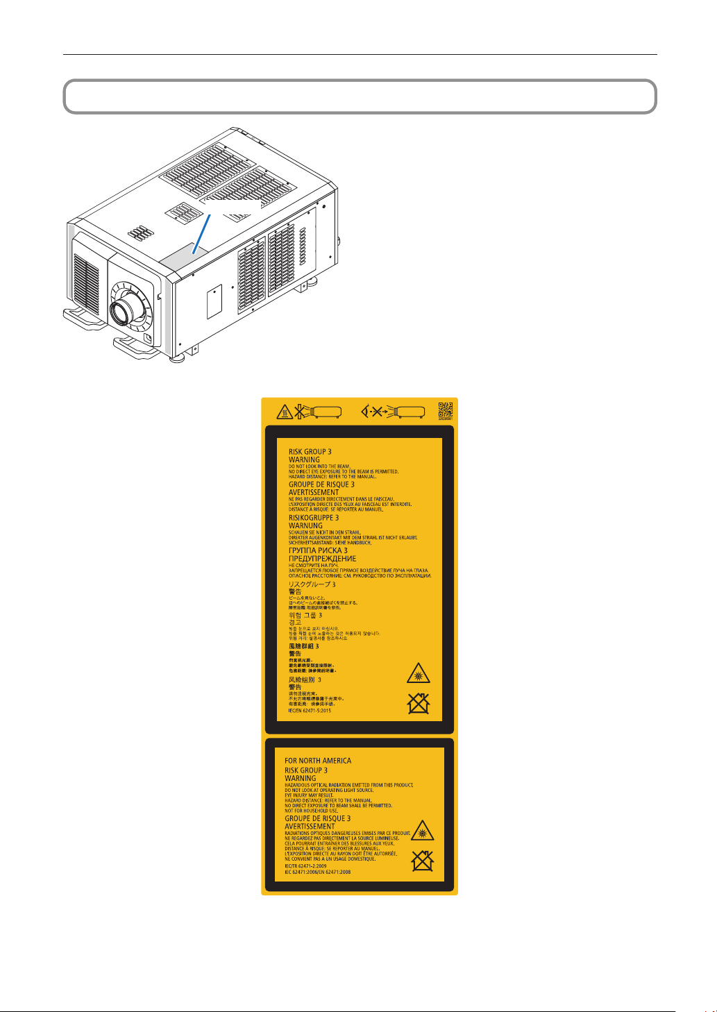
Laseraustrittsmodule
Aufkleber A
Aufkleber A: Lampenwarnschild
20
Page 21
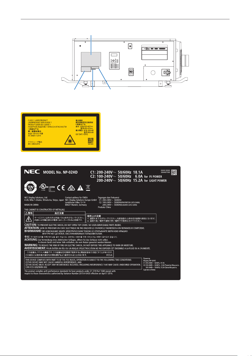
Aufkleber C
Wichtige Informationen
• Aufkleber B
Laser-Hinweisschild
• Aufkleber C
Aufkleber B
Aufkleber E
Aufkleber D
21
Page 22

Wichtige Informationen
• Aufkleber D
• Aufkleber E
22
Page 23
Wichtige Informationen
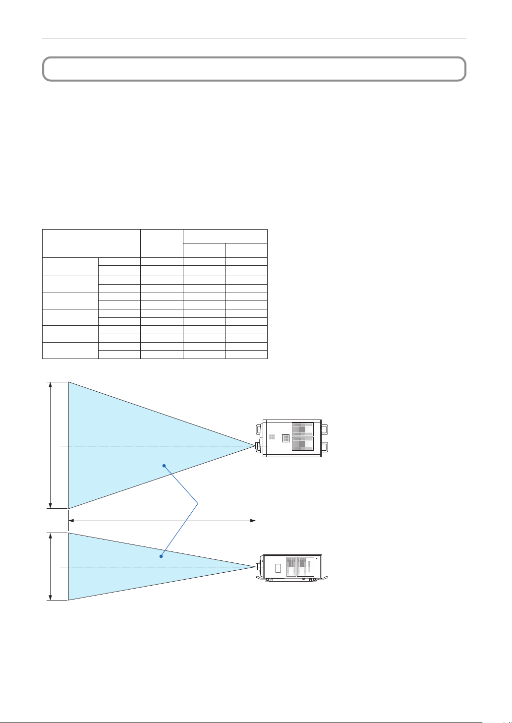
Strahlungsbereich des abgegebenen Lichts durch den Projektor(Sicherheitsabstand – HD: Hazard distance)
• Die nachfolgend abgebildete Tabelle gibt den Strahlungsbereich des abgegebenen Lichts durch den Projektor an, das als Risik-
ogruppe 3 (RG3) nach IEC62471-5 Erste Ausgabe 2015 eingestuft.
• Bitte bei der Installation des Projektors die Einschränkungen beachten.
Installieren Sie zum Schutz der menschlichen Augen vor dem RG3-Bereich eine Abdeckung.
Achten Sie darauf, dass sich bei der Installation der Abdeckung die horizontale Sicherheitszone mindestens 1,5 m vom RG3Bereich entfernt befindet.
Falls der Projektor über Kopf installiert wird, halten Sie einen Abstand von mindestens 3 m zwischen der Bodenfläche und dem
RG3-Bereich ein.
Bediener müssen den Zugang zum Strahl innerhalb des Gefahrenabstands kontrollieren oder das Produkt so hoch installieren,
dass die Augen der Zuschauer innerhalb des Gefahrenabstands nicht dem Strahl ausgesetzt werden können.
(IEC62471-5 First edition 2015)
Bildschirmgröße(m)
H V
NC-60LS12Z
NC-60LS14Z
NC-60LS16Z
NC-60LS19Z
NC-60LS24Z
NC-60LS39Z
Linse
Breit 5,0 4,2 2,2
Tele
Breit 5,5 3,9 2,1
Tele 8,0 3,9 2,1
Breit 6,0 3,8 2,0
Tele 9,5 3,8 2,0
Breit 6,5 3,4 1,8
Tele 11,0 3,4 1,8
Breit 9,0 3,8 2,0
Tele 15,5 3,7 2,0
Breit 12,9 3,3 1,7
Tele 21,5 3,3 1,7
RG3
HD(m)
7,5 4,1 2,2
H
[Draufsicht]
RG3-Bereich
HD
V
[Seitenansicht]
* Falls der Linsenversatz verwendet wird, berücksichtigen Sie bitte die Verschiebung des projizierten Bildes je nach Umfang des
Linsenversatzes.
23
Page 24
Wichtige Informationen
ACHTUNG:
Bitte beachten Sie alle Sicherheitshinweise.
Installation des Projektors
• Beachten Sie bei der Planung des Aufbaus des Projektors die Sicherheitsmaßnahmen im Installationshandbuch.
• Installieren Sie zur Gefahrenverringerung eine Wandsteckdose in Reichweite, damit der Netzstecker im Notfall herausgezogen
werden kann, oder einen Trennschalter, um die Stromversorgung zum Projektor unterbrechen zu können.
• Beachten Sie zum Schutz der menschlichen Augen vor dem RG3-Bereich die Sicherheitsmaßnahmen.
• Wählen Sie eine geeignete Linse für den Installationsort aus, und halten Sie die Sicherheitszone, die für die jeweilige Linse
vorgesehen ist, ein. Beachten Sie die entsprechenden Sicherheitsmaßnahmen, wenn Sie Einstellungen am Licht des eingeschalteten Projektors vornehmen.
• Prüfen Sie, ob die Sicherheitsmaßnahmen eingehalten wurden, wenn die entsprechende Sicherheitszone gemäß der installierten Linse eingestellt wird. Prüfen Sie dies in regelmäßigen Abständen und dokumentieren Sie die Ergebnisse.
• Weisen Sie den Administrator des Projektors (Bediener) in die Sicherheitsbestimmungen ein, bevor dieser mit dem Betrieb
des Projektors beginnt.
Verwendung des Projektors
• Weisen Sie den Administrator des Projektors (Bediener) an, den Projektor vor dem Einschalten zu überprüfen (einschließlich
der Sicherheitsprüfung des abgegebenen Lichts durch den Projektor).
• Unterrichten Sie den Administrator des Projektors (Bediener) über die erforderlichen Maßnahmen zur Kontrolle des eingeschalteten Projektors, falls ein Notfall eintritt.
• Weisen Sie den Administrator des Projektors (Bediener) an, das Installationshandbuch, das Benutzerhandbuch und die Inspektionsdokumente an einem Ort zu verwahren, an dem leicht auf diese Dokumente zugegriffen werden kann.
• Weisen Sie ihn an, zu prüfen, ob der Projektor den Standards des entsprechenden Landes und der jeweiligen Region
entspricht.
24
Page 25

Table of Contents
Introduction ......................................................................................................................................................................... 2
Important Information ........................................................................................................................................................3
Wichtige Informationen .................................................................................................................................................... 14
Installation of the light module ....................................................................................................................................... 27
1. Before Setting Up Your Projector ............................................... 40
1-1. Clearance for Installing the Projector (English) ................................................................................................... 40
1-2. Freiraum bei der Projektorinstallation (Deutsch) .................................................................................................42
1-3. Selecting the lens unit ............................................................................................................................................ 44
1-3-1. Screen Type ..................................................................................................................................................44
1-3-2. Calculating the lens zoom magnication to use ....................................................................................... 46
1-4. Carrying the projector ............................................................................................................................................48
1-5. Removing the Projector Covers .............................................................................................................................49
1-5-1. Removing and Mounting the Lens Cover ..................................................................................................51
1-5-2. Removing and Mounting the Side Panel ....................................................................................................53
1-5-3. Removing and Mounting the Filter Cover .................................................................................................. 53
2. Setting Up Your Projector .......................................................... 54
2-1. Setup Procedure ..................................................................................................................................................... 54
2-2. Projector Installation ..............................................................................................................................................55
2-2-1. Installing the Projector on the Ceiling .......................................................................................................56
2-2-2. Terms for Preparation of Frames and Ceiling Hanging Brackets ............................................................57
2-3. Selecting the Power Cable for C2 Connection (English) ..................................................................................... 58
2-3-1. AC Power Work Specications ....................................................................................................................59
2-4. Auswahl des Netzkabels für Anschluss C2 (Deutsch) ........................................................................................61
2-4-1. Netzstrom-Spezikationen .......................................................................................................................... 62
2-5. Connecting the power cable (English) ..................................................................................................................64
2-5-1. Power supply construction specications ................................................................................................ 64
2-5-2. Procedure for connecting the power cable (C1 connection) ................................................................... 71
2-5-3. Procedure for connecting the power cable (C2 connection) ................................................................... 74
2-6. Anschließen des Netzkabels (Deutsch) ................................................................................................................ 79
2-6-1. Technische Daten zum Netzanschluss ..................................................................................................... 79
2-6-2. Anschluss des Stromkabels (Anschluss C1) ............................................................................................ 86
2-6-3. Anschluss des Stromkabels (Anschluss C2) ............................................................................................ 89
2-7. Mounting the Lens Unit .......................................................................................................................................... 94
2-7-1. Part names of Lens Mount .......................................................................................................................... 95
2-8. Mounting the Option Board ...................................................................................................................................98
2-8-1. Make the option board usable ..................................................................................................................100
3. Projector Adjustment and Connecting ..................................... 102
3-1. Flow of Adjustment and Connecting ................................................................................................................... 102
3-2. Recovering from Tamper Errors ...........................................................................................................................103
3-2-1. Clearing tamper events ............................................................................................................................. 104
3-3. Turning your Projector On....................................................................................................................................106
3-4. Setting the Date and Time in the Projector ......................................................................................................... 107
3-5. Setting the Projector Projection Method............................................................................................................. 108
3-6. Adjusting the Lens ............................................................................................................................................... 109
3-6-1. Display the Test Pattern ............................................................................................................................. 109
3-6-2. Adjusting the Screen Angle ......................................................................................................................110
3-7. Connecting with the Image Input Port .................................................................................................................111
3-8. Connecting the Various Control Terminal ........................................................................................................... 112
3-9. CG adjustments .................................................................................................................................................... 11 3
25
Page 26

Installation of the light module
4. LCD Menu ................................................................................ 118
4-1. List of Menu ........................................................................................................................................................... 118
4-1-1. When You Use the Service Personnel Menu ............................................................................................ 121
4-2. Title Select ............................................................................................................................................................. 122
4-2-1. Title select (Title Memory) ......................................................................................................................... 122
4-2-2. Test Pattern ................................................................................................................................................. 122
4-3. Conguration ........................................................................................................................................................ 123
4-3-1. Light Setup ................................................................................................................................................. 123
4-3-2. Lens Control ............................................................................................................................................... 123
4-3-3. Reset ........................................................................................................................................................... 124
4-3-4. Setup ........................................................................................................................................................... 126
4-3-5. Installation .................................................................................................................................................. 128
4-3-6. Memory ....................................................................................................................................................... 133
4-4. Title Setup ............................................................................................................................................................. 134
4-4-1. Preset Button .............................................................................................................................................. 134
4-5. Information ............................................................................................................................................................ 135
4-5-1. Light ............................................................................................................................................................ 135
4-5-2. Lens Type .................................................................................................................................................... 135
4-5-3. Preset Button .............................................................................................................................................. 135
4-5-4. Usage .......................................................................................................................................................... 136
4-5-5. Error Code .................................................................................................................................................. 136
4-5-6. Version ........................................................................................................................................................ 137
4-5-7. IP Address...................................................................................................................................................137
4-5-8. Setup Date .................................................................................................................................................. 138
4-5-9. Option Status ............................................................................................................................................. 138
5. Appendix .................................................................................. 139
5-1. List of Registered Titles (when shipped from the factory) ................................................................................ 139
5-2. Error Code List ...................................................................................................................................................... 140
5-3. Remote Interlock Connector ................................................................................................................................ 146
5-4. Outline Drawing .................................................................................................................................................... 148
26
Page 27
Installation of the light module
NOTE
1
The NP-24LU01, NP-20LU01 and NP-18LU01 light modules can be used in combination with the projector head (NP-02HD). Other
light modules cannot be used in combination with the projector head.
The explanation on how to install the light module assumes the projector is as it was when shipped from the factory. In addition, in
this explanation the projector head is referred to as the “main unit”. To remove the light module, follow the procedure in reverse order.
- No one other than a specialized service person should install the light module. Otherwise the equipment could
be damaged or accidents could occur.
The main unit weighs approximately 86 kg, the light module (NP-24LU01 and NP-20LU01)* approximately 65
-
kg. When moving the unit, use a cart or a simple crane and be careful not to bang the unit against other objects. The unit should only be lifted by multiple persons, being very careful not to get their fingers crushed. Attempting to lift the unit alone could cause injury or lower back pain.
* The NP-18LU01 weighs approximately 56 kg.
- Install the light module in a place with little dust. If not, dust may enter the optical unit and decrease image quality.
- Do not loosen any screws other than those specified, and do not disconnect any connectors other than those
specified.
Preparation: Tools required for installation of the light module
Long Phillips screwdriver (500 mm or longer, magnetized)
Dedicated positioning bars: 2 (Please contact NEC Display Solutions.)
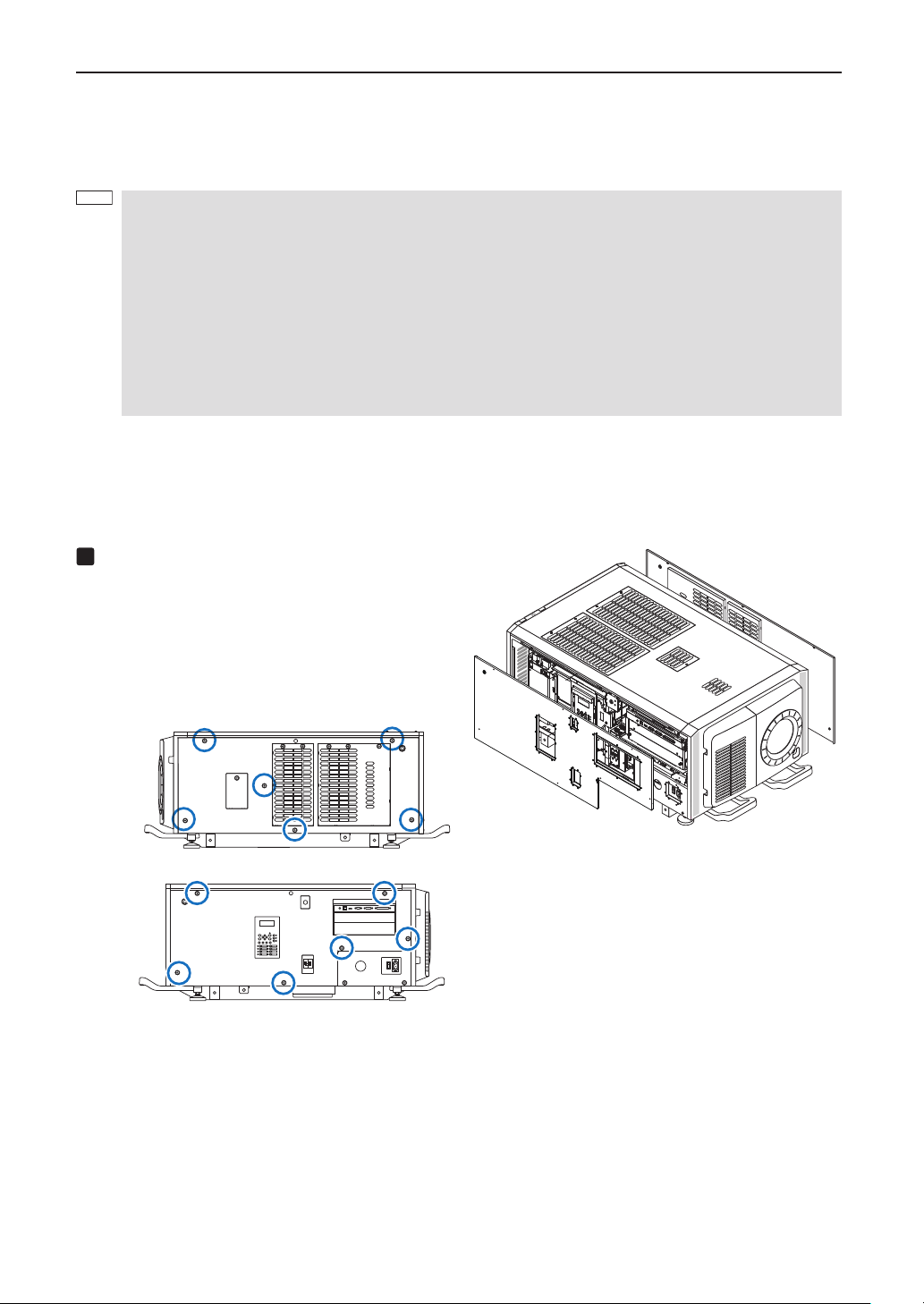
Remove the shipping reinforcement brack-
ets that are built into the main unit.
(1) Remove the left and right side panels.
Turn each of the six M4 screws counterclockwise
until they turn freely (they do not come off), open
the panel a little, then lift the panel (to detach it
from the hooks) and remove it.
27
Page 28
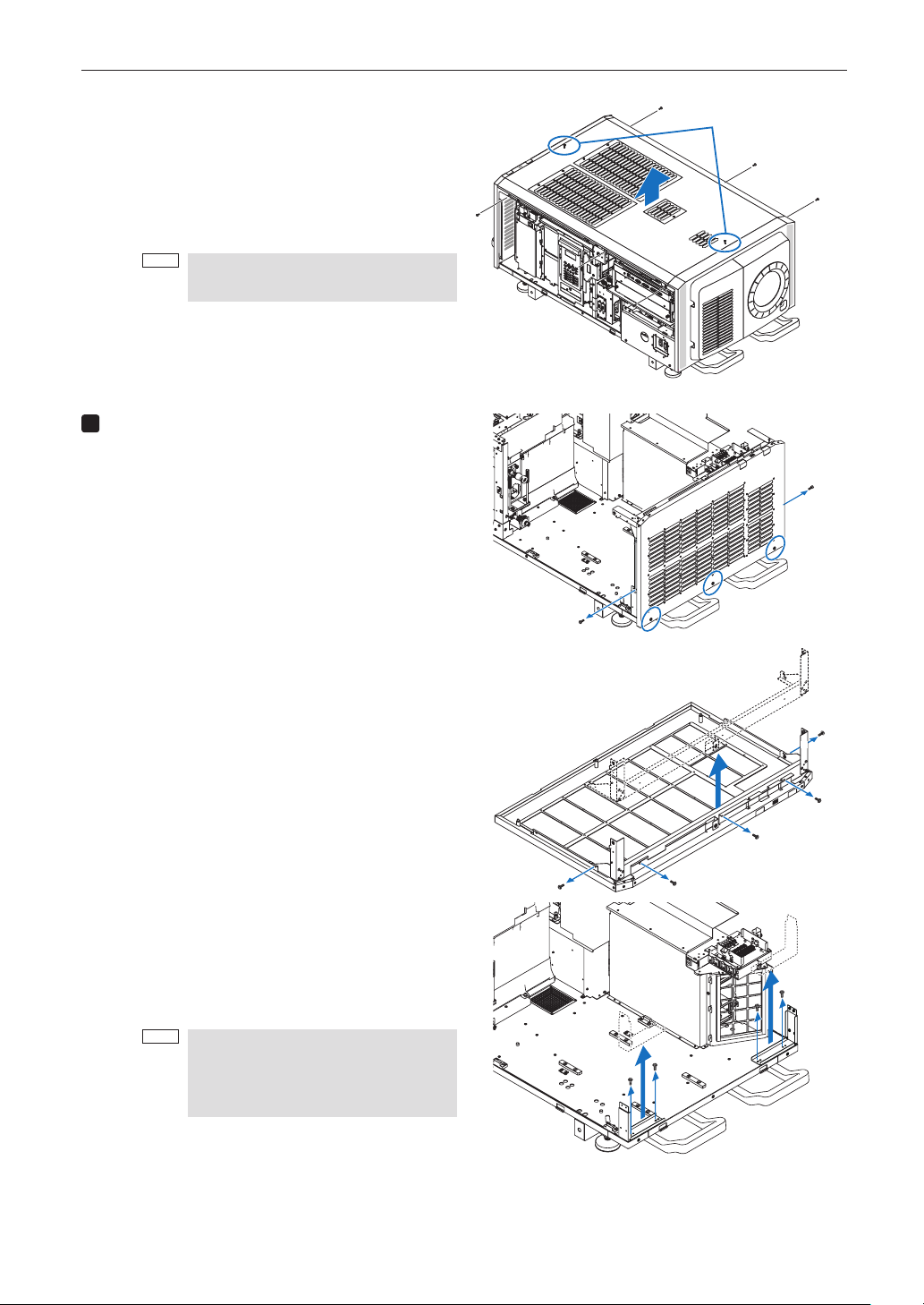
Installation of the light module
(2) Remove the top panel.
Remove the three M4 screws (silver) on the left
and right sides respectively.
Turn the two M4 screws (black) at the front and
back centers of the top panel until they turn
freely (they do not come off), then lift the panel
and remove it.
NOTE
The six screws removed in (2)
used in step 8 (4). Do not discard them.
2
Remove the shipping reinforcement brack-
will be
①
ets that are built into the main unit.
(1) Turn the M4 screws at the left and right sides near
the bottom of the rear panel counterclockwise and
remove them.
Next, turn the three screws along the bottom edge
counterclockwise until they turn freely (they do not
come off) and remove.
The rear panel detaches from the base.
These screws do not come off.
(2) Remove the five M4 screws from the rear panel
and remove the shipping reinforcement brackets.
(3) Remove the M4 screws (two each) from the left
and right shipping reinforcement brackets on the
base, then remove the shipping reinforcement
brackets.
The removed rear panel will be mounted on the
light module later.
NOTE
The nine M4 screws removed in (2)
and (3) will be used in step 8 (1) (seven
screws) and step 8 (4) (two screws). Do
not discard them.
28
Page 29
3
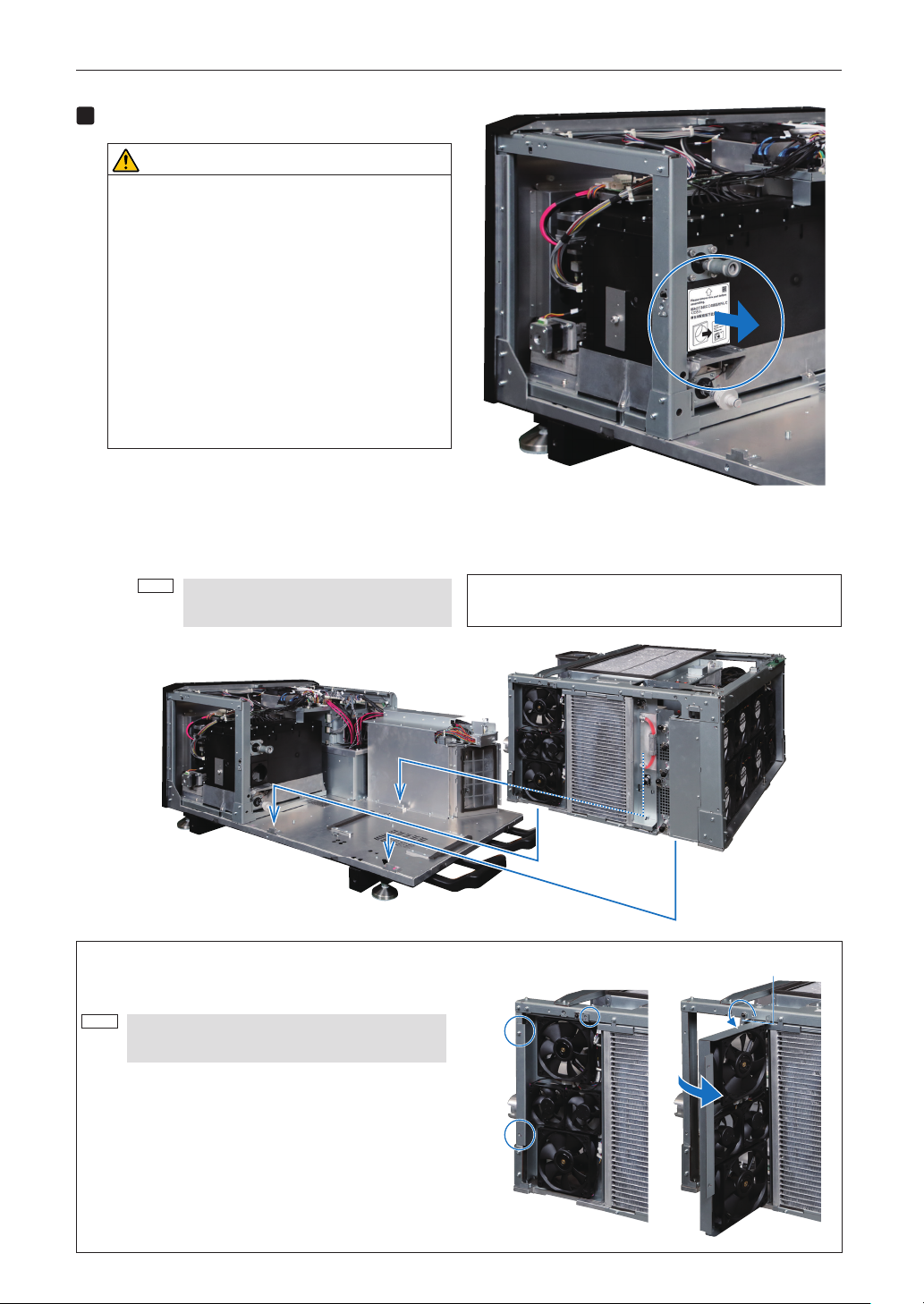
Place the light module on the main unit.
NOTE
CAUTION
The light module (NP-24LU01 and NP-
・
20LU01)* weighs approximately 65 kg. To
avoid lower back pain, it should only be installed by multiple people.
* The NP-18LU01 weighs approximately
56 kg.
When placing it on the main body, be care-
・
ful not to crush your fingers.
There are four mounting screw holes for eye
・
bolts in the light module.
Do not use them for anything other than
suspending the light module. Otherwise the
projector may be damaged.
(1) Remove the dustproofing section of the light
source socket.
(2) Line up the notches in the light module's base with
the three stoppers and place them over the inside
of the stoppers.
NOTE
Make sure that the light module's base is
flush against the main unit.
Installation of the light module
If placing the light module on the main unit by hand, open the
fan bracket and hold the upper part of the frame.
[Light module]
[Main unit]
Opening the fan bracket
Remove the three M4 screws, open the fan bracket, then turn
the stopper downward.
Be sure to apply the stopper to prevent crushing
your fingers.
When closing the fan bracket, set the stopper back in its original position and tighten it together with the frame.
Stopper
29
Page 30
Installation of the light module
4
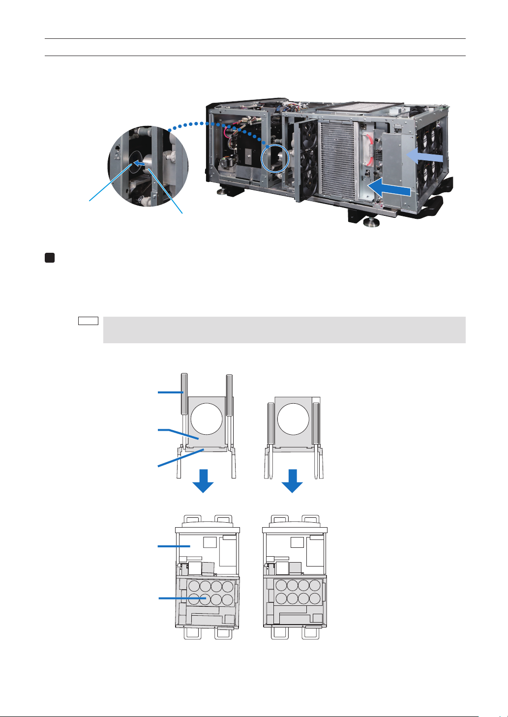
If the dedicated positioning bars do not fit into the bracket,
(3) Slide the light module forward.
When this is done, the tip of the light module's light flux pipe is inserted into the light source socket of the main
unit.
Light source socket
Light flux pipe
Fine-adjust the light module's mounting position.
(1) Insert the two dedicated positioning bars into the light module (see the figure).
If they enter up to the base, there is no need for the adjustment.
If the dedicated positioning bars do not fit into the bracket, move the light module a little and find the position at
which they can be inserted.
NOTE
To avoid bending the dedicated positioning bars, do not shake the light module left and right when lining
up the bars with the holes.
Dedicated positioning bar
Light flux pipe of light module
Positioning bracket
Projector
Light module
the alignment of positions is not correct.
If the dedicated positioning bars insert
into the bracket smoothly,
the alignment of positions is correct.
[Cross-section image view]
[Top image view]
30
Page 31
Installation of the light module
5
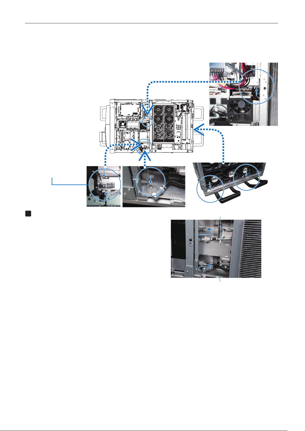
(2) Once the position is set, tighten with the four M6 cross-slot upset screws (temporarily fixed to the light module
base) and the two M5 cross-slot upset screws (included with the main unit).
(3) Remove the dedicated positioning bars.
Use the M5 screws included
with the main unit for these two
screws.
Connect the cooling hoses.
Press the joints of the two cooling hoses on the main
unit and the light module in until they click into place.
The joint locks when it is pressed in.
Pull to check that the hoses do not disconnect.
- To disconnect, press in the white button and pull out.
Cooling hose
Cooling hose
31
Page 32

Installation of the light module
6
7
Close the fan bracket and fasten it.
(1) Rotate the stopper clockwise and line it up with the
screw hole.
(2) Close the fan bracket and tighten it with the three
M4 screws.
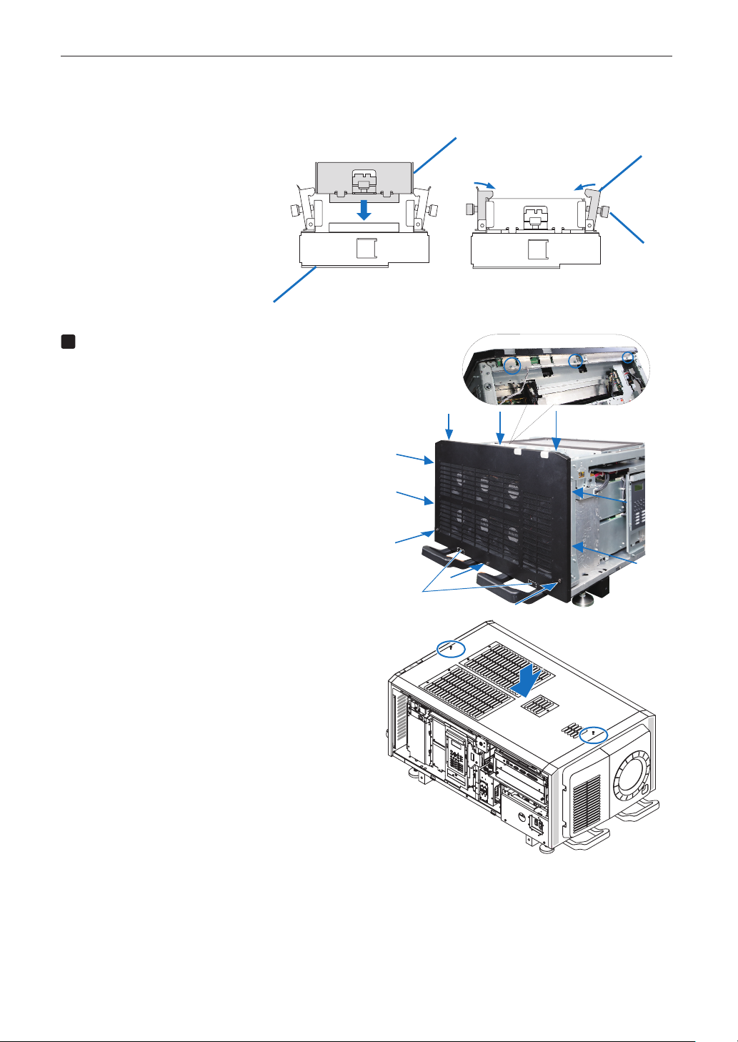
Mount the quick release board onto the
light module's connector holder.
(1) Turn the knobs of the quick release board that is
temporarily fixed to the main unit's frame until they
turn freely and remove the quick release board.
Stopper
Quick release board
32
Page 33
Installation of the light module
8
(2) Now carefully insert the quick release board into light module's connector holder, attach the left and right hooks to
the ends of the quick release board, then turn the knobs to fasten.
Quick release board
Hook
Connector holder
Mount the rear panel and the top panel.
(1) Attach the two hooks on the main unit's base to
the rear panel, then use the seven M4 screws removed in step 2 (three at the top, two at the right
and two at the left) to fasten.
(2) Tighten the three screws at the bottom of the rear
panel.
Knob
(3) Place the top panel on the main unit, then tighten
the two screws at the front and back centers of the
top panel.
Hook
33
Page 34

Installation of the light module
(4) Use the six M4 screws (silver) removed in step 1 (2) and the two M4 screws removed in step 2 to fasten at four po-
sitions respectively on the left and right sides.
When doing this, tighten the screws in the notch-less screw holes on left and right sides.
Notch
9
Mount the left and right side panels.
(1) Insert the service key into the key in the panel and
turn it clockwise to unlock.
When unlocked, the key cannot be removed.
(2) Place the lower edges of the panel onto the two
hooks on the main unit and close the panel.
Service key
Hook
(3) Tighten the side panel's seven fixing screws.
(4) Turn the service key counterclockwise to lock it.
Upon shipment from the factory, the notch filter kit (NFK-G24) for the NP-24LU01 and NP-20LU01 is installed on the
main unit.
When using the main unit in combination with the NP-18LU01 light module, replace the notch filter kit with the NFK-G18
that is included with the main unit. For instructions on replacing the notch filter, see “Replacing the Notch Filter” on
page 00.
34
Page 35

Installation of the light module
Replacing the notch filter kit
Upon shipment from the factory, the notch filter kit (NFK-G24) for the NP-24LU01 and NP-20LU01 light modules is installed on the
main unit. When using the main unit in combination with the NP-18LU01 light module, replace the notch filter kit with the NFK-G18
that is included with the main unit.
(for the NP-18LU01 light module)
CAUTION
• Before replacing the notch filter, turn off the power, wait for the cooling fans to come to a complete stop, turn off the projector's
power switch and the light source's power switch, shut off the AC power, then check to make sure that the main unit has cooled
down sufficiently. Removing the notch filter kit while the unit is operating may cause burns or electric shock when inside parts
are touched.
• Replace the notch filter kit in a place with little dust. Also be careful not to touch the filter or to get dust or the like on it.
Notch filter cover
1
Remove the notch filter cover.
(1) Turn the screw counterclockwise until it turns freely,
then pull and open.
The screw does not come off.
(2) Lift the notch filter cover upward and remove it.
(1)
(2)
35
Page 36

Installation of the light module
2
3
Take out the notch filter kit.
(1) Turn the knob counterclockwise until it turns freely.
The knob does not come off.
(2) Pull the notch filter kit straight out to remove it.
Install the new notch filter kit (NFK-G18).
(1) Point the arrow upwards and slowly insert the
notch filter kit into the insertion slot in the main unit,
being careful not to hit the filter section.
NOTE
- Check the notch filter kit's model
name.
- Do not touch or hit the filter section.
(1)
(2)
(1)
Insertion slot
(2)
Filter section
(2) Turn the knob clockwise to tighten it.
4. Mount the notch filter cover.
(1) Insert the two tabs on the notch filter cover into the
grooves in the main unit, then close the cover.
(2) Turn the screw clockwise to tighten it.
Store the notch filter kit that was removed in a safe
place.
(1)
(2)
36
Page 37
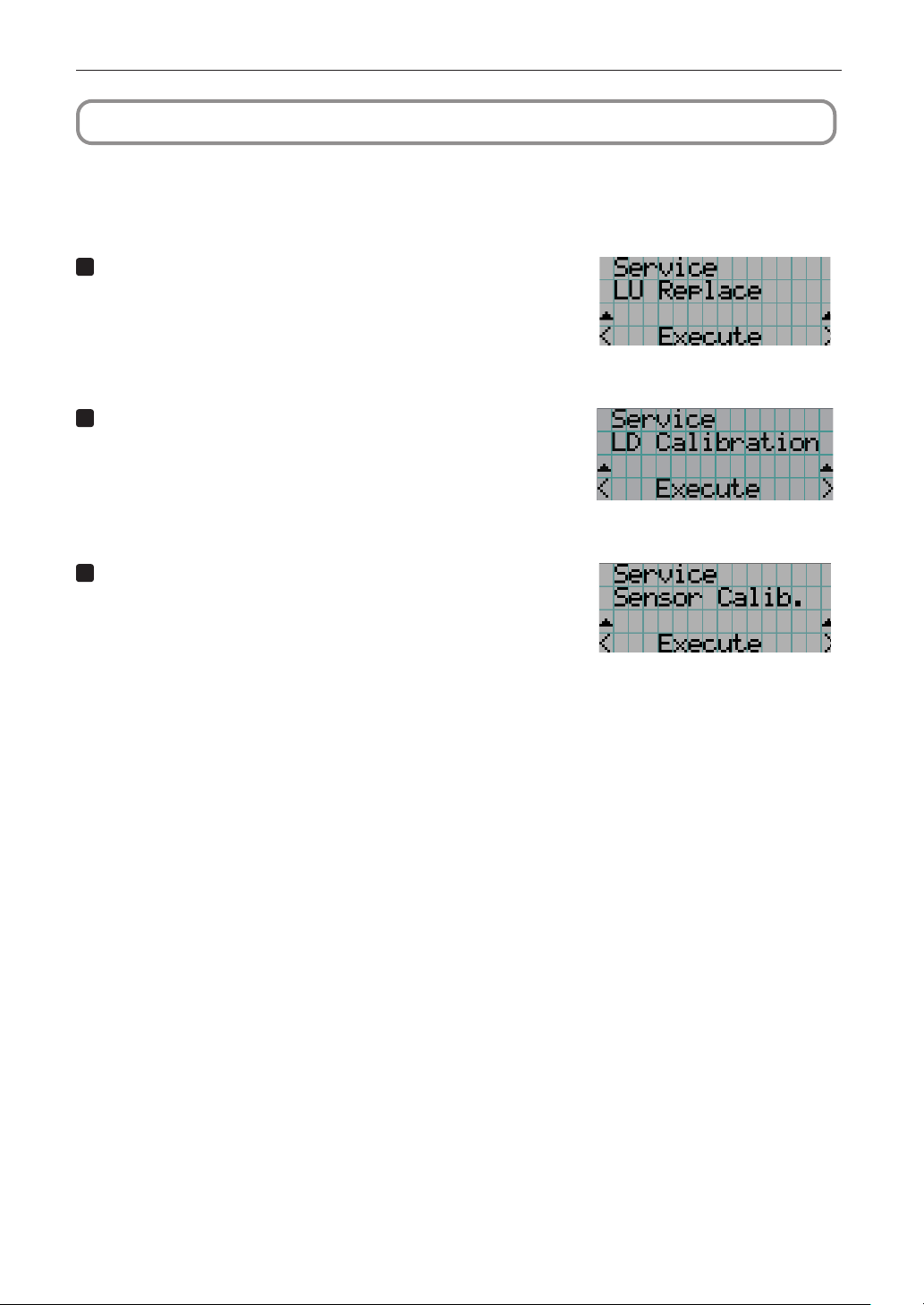
Installation of the light module
1
3
Maintaining the information of light module
Store the various information and the initial adjustment data of the light module to the projector head.
To execute the following steps, first you need to log in the projector main unit as a serviceman.
To use the menu for Serviceman, refer to “4-1-1. Using the Menu for Serviceman” (page 121)
Store the various information of the light module.
(1) Press the MENU operation button to display the adjustment menu on
the LCD panel.
(2) Select Configuration → Installation → Service → LU Replace and ex-
ecute it.
2
Measure the adjustment data on the light source of the
light module and store them.
(1) Press the MENU operation button to display the adjustment menu on
the LCD panel.
(2) Select Configuration
ecute it.
Measure the initial brightness value of the light source of
the light module and store them.
(1) Press the MENU operation button to display the adjustment menu on
the LCD panel.
(2) Select Configuration → Installation → Service → Sensor Calibration and
execute it.
→
Installation → Service → LD Calibration and ex-
37
Page 38

Installation of the light module
1
2
3
4
Shadow adjustment
If the illumination position of the light source deviates, shadows will appear around the projection screen. Shadow adjustment
consists of adjusting for this deviation. Perform shadow adjustment when replacing the light module.
WARNING
No one other than a specialized service person should perform this adjustment. Doing so may result in
・
electric shock or short circuits.
Do not drop any screws, etc. Doing so may cause short circuits.
・
Shadow adjustment is performed with the power turned on. Do not short-circuit the circuit boards with
・
the tools.
Before removing or mounting external panels and circuit boards, turn off the main unit's power, wait for
・
the cooling fans to come to a complete stop, then shut off the supply of AC power to the projector and
the light source with a circuit breaker, etc. After this, check that the main unit has cooled down sufficiently before performing the adjustment.
WARNING
Do not look at the lens during projection. Doing so may damage your eyes.
・
Required tools: #2 Phillips screwdriver
5.5 mm nut driver
Remove the right side panel.
See page 53
Remove the IF board.
Remove the six M3 screws, then remove the IF board.
NOTE
- Do not disconnect the board connector.
Turn on the projector's power.
Turn on the power of the projector and the light source
and warm up for about 15 minutes.
Refer to page 106 for instructions on turning on the
power.
Select the shadow adjustment mode from
the adjustment menu.
(1) Press the MENU operation button to display the
adjustment menu on the LCD panel.
(2) Select Installation
Note that you must log in to the projector with Ad-
vanced User privileges or higher in order to access
“Service Adj.”.
→
Service Adj. → Shadow Adj.
IF board
38
Page 39
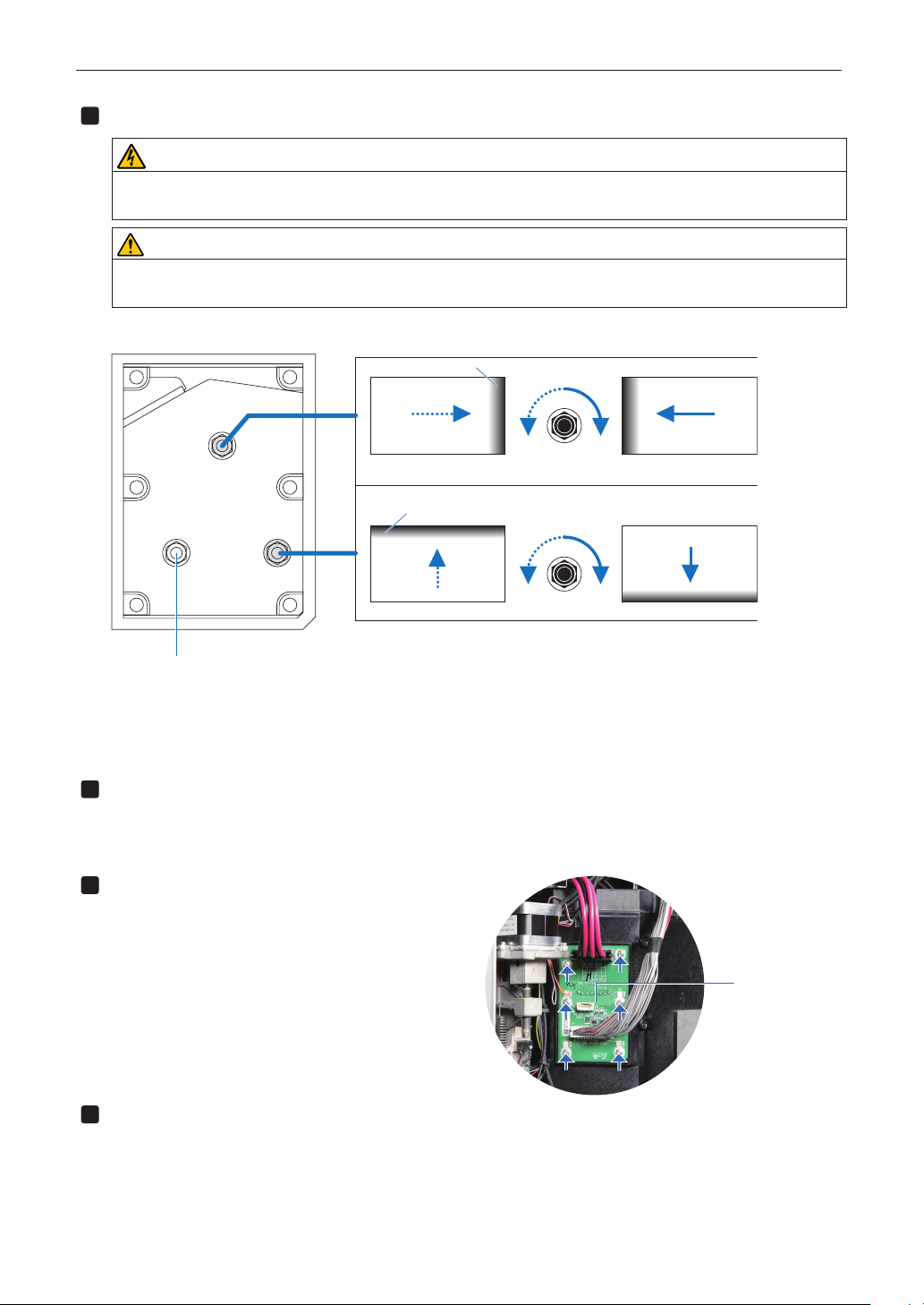
Installation of the light module
5
6
Adjust the illumination position of the light source.
CAUTION
Do not short-circuit the circuit boards with the tools.
・
Do not touch anything other than the shadow adjustment nut.
・
CAUTION
Strong light is projected during operation, so do not look into the lens. Doing so may cause dam-
・
age to the eyes.
(1) Turn the nut to adjust so that no shadows are displayed on the projection screen.
Shadow
Adjusting horizontally
ClockwiseCounterclockwise
Do not touch this nut.
(2) Cancel the Shadow Adj menu.
Turn off the projector main unit.
Turn off the projector's power.
Turn off all power to the projector and shut off the AC
power supply.
7
Mount the IF board.
Mount the IF board with the six M3 screws.
Shadow
Adjusting vertically
ClockwiseCounterclockwise
IF board
8
Mount the right side panel.
See page 52
This completes shadow adjustment.
39
Page 40
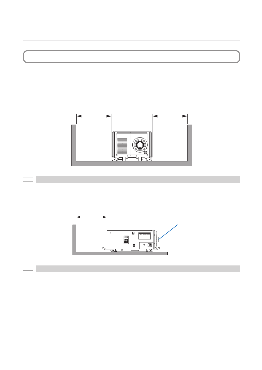
1. Before Setting Up Your Projector
1-1. Clearance for Installing the Projector (English)
Allow ample clearance between the projector and its surroundings as shown below.
Avoid installing the projector in a place where air movement from the HVAC is directed at the projector.
Heated air from the HVAC can be taken in by the projector’s intake vent. If this happens, the temperature inside the projector will
rise too high causing the over-temperature protector to automatically turn off the projectors power.
Example 1 – If there are walls on both sides of the projector.
60cm/23.6"
or greater
The drawing shows the proper clearance required for the front, back and top of the projector.
NOTE
60cm/23.6"
or greater
Example 2 – If there is a wall behind the projector.
(1) For floor installation:
70cm/27.6"
or greater
The drawing shows the proper clearance required for the front, sides and top of the projector.
NOTE
Lens
40
Page 41

Before Setting Up Your Projector
(2) For ceiling mounting:
30cm/12"
or greater
Lens
70cm/27.6"
or greater
• The drawing shows the proper clearance required for the front, sides, back and bottom of the projector.
NOTE
• If suspending the projector 30 cm/12 inches away from the ceiling, allow ample clearance for all four sides and the
under the projector.
41
Page 42

Before Setting Up Your Projector
HINWEIS
HINWEIS
1-2. Freiraum bei der Projektorinstallation (Deutsch)
Achten Sie auf ausreichenden Freiraum zwischen dem Projektor und seiner Umgebung, wie unten gezeigt.
Vermeiden Sie es, den Projektor an einer Stelle zu installieren, an der er den Luftströmungen von Klimaanlagen ausgesetzt ist.
Die aufgeheizte Luft aus einer Klimaanlage kann vom Lüftungseinlass des Projektors aufgenommen werden. Dadurch wird die
Innentemperatur des Projektors zu stark erhöht, was dazu führt, dass der Überhitzungsschutz des Projektors diesen automatisch
ausschaltet.
Beispiel 1 - Wenn sich Wände auf beiden Seiten des Projektors befinden.
60 cm
oder mehr
Die Abbildung zeigt den ordnungsgemäßen Abstand für die Vorder-, Rück- und Oberseite des Projektors.
60 cm
oder mehr
Beispiel 2 - Wenn sich eine Wand hinter dem Projektor befindet.
(1) Bei Installation auf einem fl achen Untergrund:
70 cm
oder mehr
Linse
Die Abbildung zeigt den ordnungsgemäßen Abstand für die linke, rechte, Vorder- und Oberseite des Projektors.
42
Page 43

Before Setting Up Your Projector
HINWEIS
(2) Bei der Deckenmontage:
30 cm
oder mehr
Linse
70 cm
oder mehr
• Die Abbildung zeigt den ordnungsgemäßen Abstand für die linke, rechte, Vorder-, Rück- und Unterseite des
Projektors.
• Wenn Sie den Projektor 30 cm von der Decke entfernt installieren, achten Sie auf ausreichende Freiräume auf allen
vier Seiten und unter dem Projektor.
43
Page 44
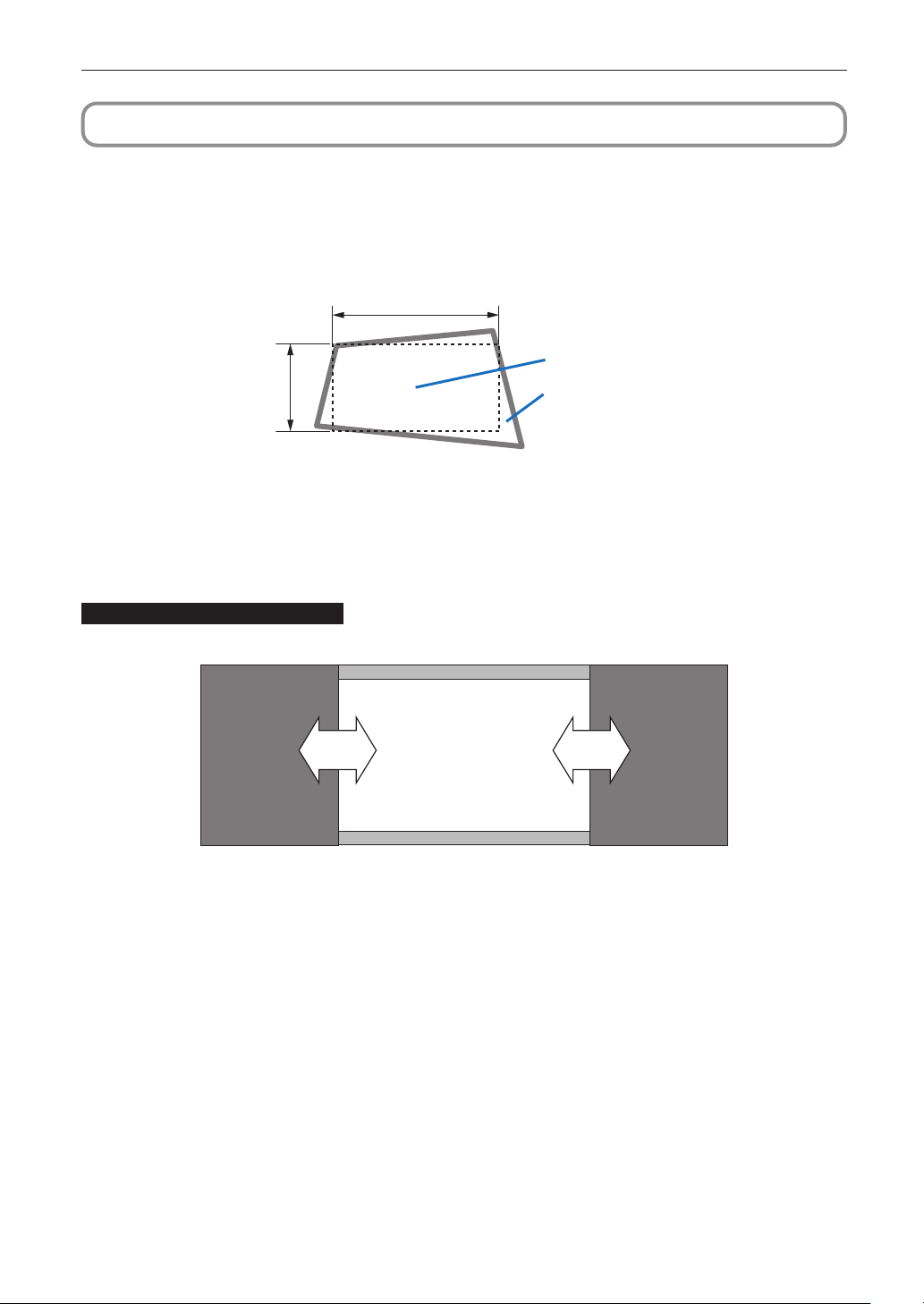
Before Setting Up Your Projector
1-3. Selecting the lens unit
This section provides guideline information on how to select the screen size, the projector mounting position, and the type of lens
unit that is appropriate for your presentation purposes. Multiple lens units are sold separately as options for this projector. Select
an appropriate lens unit according to the environment in which your projector is installed. Note that all descriptions given in this
manual assume the angle of projection is zero degree. In the case of projection from an upper position or from the left or right, it is
necessary to calculate the width for the minimum projected image at a size larger than the screen size.
Width of minimum
Screen
Projected image
1-3-1. Screen Type
The following two types of screen masks can be used for the DLP Cinema Projector. Check the screen mask for your projector for
its type before selecting lens units, because types of lens units to be used on the projector and its settings depend upon the type
of screen mask you use.
Horizontal moving screen mask
Screen masks move horizontally to adjust the screen.
ScreenScreen mask Screen mask
44
Page 45

Vertical moving screen mask
Screen masks move vertically to adjust the screen.
Before Setting Up Your Projector
Screen mask
Screen
Screen mask
45
Page 46
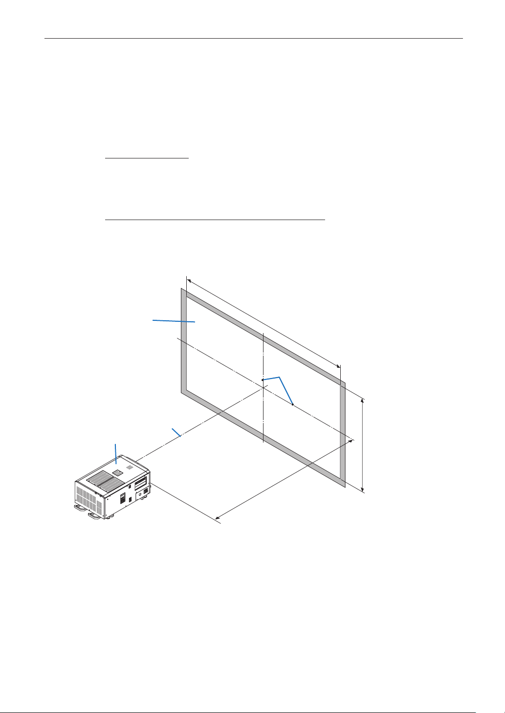
Before Setting Up Your Projector
1-3-2. Calculating the lens zoom magnication to use
The lens zoom magnification required when installing the projector is calculated using the following method.
(1) Calculate the lens zoom magnification for SCOPE projection.
(2) Calculate the lens zoom magnification for VISTA (FLAT) and HDTV projection.
(3) Select the lens that satisfies the zoom magnification calculated in (1) and (2).
SCOPE projection:
Lens
magnification
Length of projection (L)
=
Screen width (W)
VISTA (FLAT)/HDTV projection:
Lens
magnification
Note: Number of pixels per horizontal line: 1998 for VISTA (FLAT); 1920 for HDTV
Select a lens that meets the magnification requirement for SCOPE, VISTA (FLAT), and HDTV screen types.
=
Screen width (W) × (2048 ÷ (Number of pixels per horizontal line × 2))
Screen
Projector
Length centerline
Length of projection (L)
Screen width (W)
Centerlines
Screen height (H)
46
Length of projection (L)
Page 47
Before Setting Up Your Projector
Option lenses
The lens units that can be attached to this projector are shown in the following table.
MODEL Magnifying
NC-60LS12Z
NC-60LS14Z
NC-60LS16Z
NC-60LS19Z
NC-60LS24Z
NC-60LS39Z
Examples of selecting the lens unit
If the “projection distance (L) = 30 m, the screen width (W) = 15 m”:
1.20 - 1.81
1.40 - 2.05
1.59 - 2.53
1.90 - 3.25
2.40 - 3.90
3.90 - 6.52
SCOPE projection =
VISTA (FLAT) projection =
HDTV projection =
30m
15m
30m
15m × (2048 ÷ 1998)
30m
15m × (2048 ÷ 1920)
= 2.0x
= 1.95x
= 1.88x
Therefore, the following lens units, which satisfy the magnifications in all of the above projections, are selected.
• NC-60LS16Z
47
Page 48

Before Setting Up Your Projector
1-4. Carrying the projector
WARNING
• When moving the projector, it should be carried by holding the handles or hook on the base of the unit by 6 or more people.
• When moving the projector, first turn off the power and always disconnect the power plug from the electrical outlet, and check
that all of the connecting cables between equipment and the lenses have been removed.
• For C1 connection, turn off the projector, shut down AC power by using a circuit breaker.
• For C2 connection, turn off the projector, shut down the AC power to the projector and the light using a circuit breaker.
Handles
Hook
Hook
Handles
48
Page 49
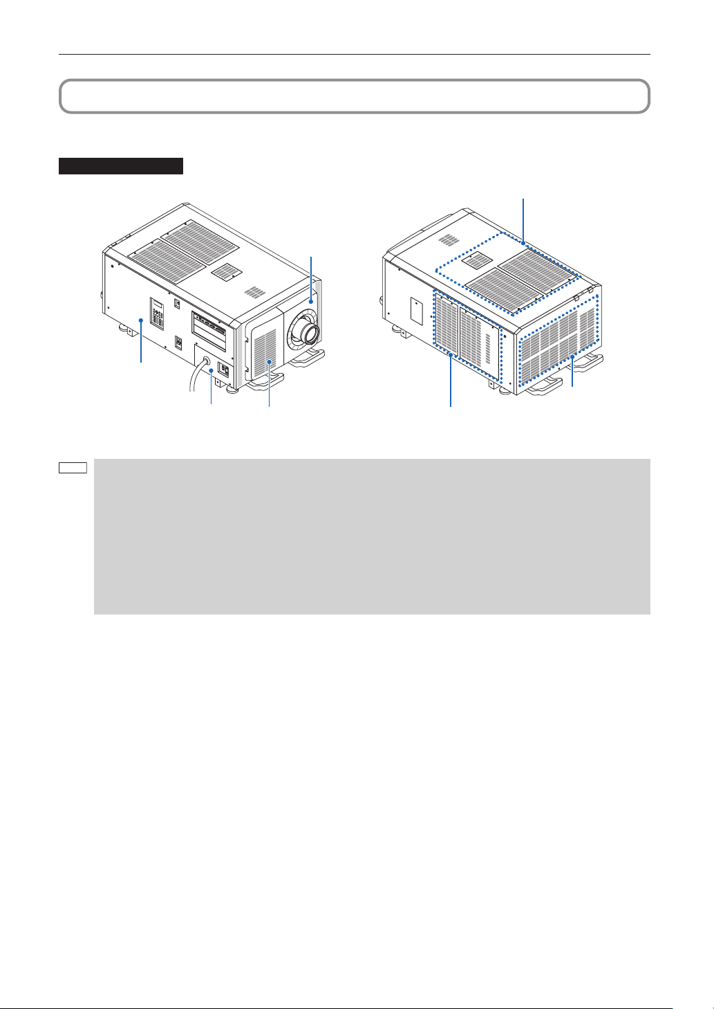
Before Setting Up Your Projector
1-5. Removing the Projector Covers
This section provides guideline information on how to remove and mount covers on the projector.
Name of the cover
Air inlet (Filter cover / Filter)
Lens cover
Side panel
Plate inlet
Air inlet (Filter cover / Filter) Air inlet (Filter cover / Filter)
Air outlet
• “Side panel” and “Lens cover” are equipped with key locks. Special keys (service key) are required to remove or
NOTE
mount them. Refer to “Position of the key locks on the covers” (page 50) for details.
• If you remove the lens cover or side panel, a tamper event is detected by the tamper detection circuit. When you
start the projector after attaching the cover, the following error message is displayed on the LCD screen of the
projector main unit.
- “IMB: Service Door Tamper”
• Encrypted contents cannot be displayed while an error message is being displayed. Refer to “3-2. Recovering from
Tamper Errors” (page 103) for details on how to clear the error message.
• Do not turn on the power when the lens cover and the side panel are removed.
• When removing the lens cover, return the lens shift to the center position before turning off the power.
49
Page 50

Before Setting Up Your Projector
Position of the key locks on the covers
When removing or attaching a cover of the projector main unit, the lock needs to be unlocked using the included service key. The
positions of the locks on each of the covers are as follows.
WARNING
TO REDUCE THE RISK OF ELECTRIC SHOCK AND LASER RADIATION, DO NOT OPEN COVER. NO USER-SERVICEABLE
PARTS INSIDE. REFER SERVICING AND INSTALLATION TO QUALIFIED SERVICE PERSONNEL AND INSTALLATION
PERSONNEL.
When a cover is removed, the power to the unit is automatically turned off by the safety protection system.
NOTE
Lens Cover
The lock is unlocked when attaching or removing lenses (page 51, 94).
Just canceling the lock will not allow you to remove the service key.
Side Panel
The lock is unlocked when attaching or removing the option board (page 98).
Just canceling the lock will not allow you to remove the service key.
50
Page 51

1-5-1. Removing and Mounting the Lens Cover
1
2
Preparation: Service key (attached goods)
Remove the front lter cover.
Pull the filter cover in the direction of the arrow to remove it.
Handle
Unlock the lens cover.
Unlock the cover using the service key.
Before Setting Up Your Projector
51
Page 52

Before Setting Up Your Projector
3
NOTE
Remove the lens cover.
The lens cover is secured to the projector body by two claws each at the cover top and bottom.
Hold the cover sides and pull toward you.
Handle
Handle
• This completes removing the lens cover. To mount the cover, perform the removal procedure in reverse. Make sure to lock the
key.
Hook
* Lens cover removed condition
If the cover is not properly mounted, an error may occur. Securely push all claws into the position.
52
Page 53

Before Setting Up Your Projector
1
2
3
1-5-2. Removing and Mounting the Side Panel
Preparation: Phillips-head screwdriver (No.2), service key (attached goods)
Loosen the seven xing screws on the side panel.
Loosen four screws on the side panel until they are free to spin. The screws do not detach from the panel.
Unlock the lock on the side panel.
Use the service key to unlock the lock.
Remove the side panel.
The side panel is fixed in place by hooks at the bottom (in 2 locations). Tilt the side panel toward you and pull up to remove
it. Do not use force when tilting the side panel.
Hook (2 locations)
This completes removing the side panel. To mount the side panel, perform the removal procedure in reverse. Make sure that you
do not forget to tighten the screws or to lock the key lock.
1-5-3. Removing and Mounting the Filter Cover
Refer to the user’s manual for details on how to remove and attach the filter cover.
53
Page 54

2. Setting Up Your Projector
2-1. Setup Procedure
Set up the projector according to the procedure below. This chapter describes the installation of procedure until turning on of the
power.
• Step1
Projector Installation (See page 55).
• Step2
Selecting the Power Cable (See page 58).
Connecting the Power Cable (See page 64).
• Step3
Mounting the Lens Unit (See page 94).
• Step4
Mounting the following optional parts as required.
- Installing the Media Block (NP-90MS01/NP-90MS02) (See page 98).
54
Page 55
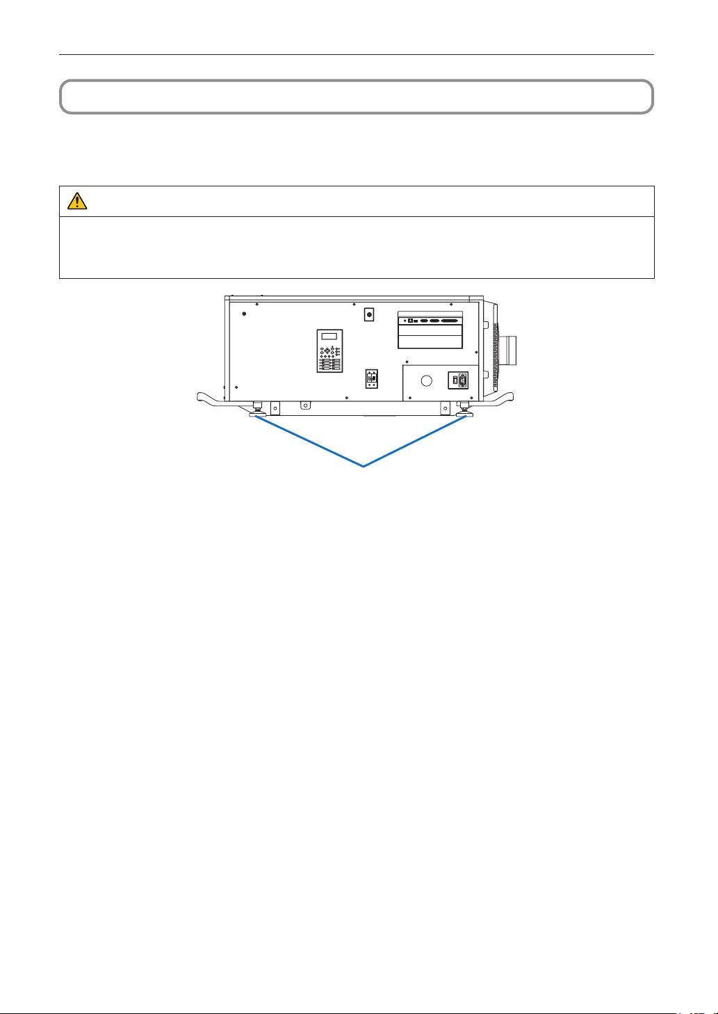
Setting Up Your Projector
2-2. Projector Installation
Move the projector to the projection position and install it corresponding to the screen and projection conditions.
To correct the inclination to the right or left of the projector, use the level adjusters at 4 positions. You can extend the level adjuster
to 10 mm at the maximum (Rotate it counterclockwise for extension).
CAUTION
• Do not extend the adjuster by more than 10 mm. Rotating it forcefully may cause the adjuster to come off or be damaged.
• To adjust the level adjusters of the projector, extend the two level adjusters at the front and the back at the same time so that
the weight is imposed to them equally. If you adjust only one adjuster, the weight is not imposed equally, which may result in
level adjuster failure.
Level adjusters (in four positions)
55
Page 56

Setting Up Your Projector
270
213.5
2-2-1. Installing the Projector on the Ceiling
To install the projector on the ceiling, install it by referring to the following specifications.
30
Max M8x20
55.5
214
720
586
Max M8x20
140
300 253300
874
56
Unit : mm
The ceiling mounting surface
Lens center
(Lens shift 0)
48.5
275
211
600
Lens center
(Lens shift 0)
Max M8x20
64
509
445
Page 57

Setting Up Your Projector
NOTE
2-2-2. Terms for Preparation of Frames and Ceiling Hanging Brackets
Ask whoever is installing the projector to prepare a specifically designed frame and ceiling hanging brackets (Charged Service).
Take note of the following upon its design.
- There are intake openings and exhaust openings on the side of the main unit, exhaust openings on the rear, intake openings
on the front, intake openings on the top side. Make sure that the design does not obstruct these openings. Also make sure to
secure enough space to allow easy removal of the filter cover for cleaning the filter.
- Remove the adjusters on the main unit if they will interfere with the frame. The adjusters can be removed by turning them.
- Attach the frame and ceiling hanging brackets to the screw holes (in four positions) provided on the bottom surface of the main
unit for ceiling hanging installation.
Refer to the specification sheet for dimensions between the centers of the screw holes. Note that the screw holes on the main
unit have the dimensions of an M8 thread and a maximum depth of 20 mm (the lengths of the bolts are to be calculated according to the design).
- Horizontal adjustment mechanism (for example, bolts and nuts in four positions)
- Design the frame so that it will not easily collapse.
- To prevent ceiling collapse, the ceiling should be able to support the combined weight (158 kg*1) of the projector (150 kg*2) and
lens (8 kg) for an extended period of time, and the installation must be in accordance with any local building codes.
1
*
When the light module NP-18LU01is installed, the weight is about 149 kg.
*2 When the light module NP-18LU01is installed, the weight is about 141 kg.
Make sure there are at least six people taking part when lifting this unit.
Attempting to lift this unit alone may lead to injury or cause pain in the lower back.
57
Page 58

Setting Up Your Projector
NOTE
2-3. Selecting the Power Cable for C2 Connection (English)
The power cable for C2 Connection is not included with the projector. Refer to “2-3-1. AC Power Work Specifications” (page 59)
and provide the necessary power cable.
WARNING
Carefully read the contents described in this section before connection and connect the cables according to the proper procedure. Inappropriate handling may cause fatal, serious or other bodily injuries due to fire or electric shock.
CAUTION
• Before connecting the power cables, check that the main power switch of the projector is turned off. Implement the connec-
tion with AC power shut off.
• Be sure to ground the equipment to ensure safety. Use a power cable that meets the standards and power supply voltage of
the country where you are using the projector (page 59), and always connect the equipment to the ground. If the ground is
not connected, it may cause electrical shocks.
• When connecting the power cable plugs to the AC IN and the electrical outlet, securely insert the plugs all the way in. If the
connection between the power cable plug and the electrical outlet is loose, the plug area may generate heat, causing burns
and accidents.
• In order to prevent the power plug from being disconnected from the projector, fix the power cable by using the power cable
stopper supplied with this unit. For how to use the power cable stopper, refer to “Attaching the power cable stopper” (page
59).
• Install the electric outlet nearby the projector main unit so that the power supply can be cut by unplugging the AC
power cable.
• When plugging in or unplugging the AC power cable, make sure that the main power switch is pushed to the [O]
position. Failure to do so may cause damage to the projector.
• Do not use a three-phase power supply. Doing so may cause malfunction.
58
Page 59

Setting Up Your Projector
NOTE
2-3-1. AC Power Work Specications
ACpowersupplyequipment
Do not use any voltage other than those shown below for the AC power supply connected to the projector.
For C2 connection (when using two different power cables to supply the AC power to the projector and the light source
separately)
- AC100– 240 V single phase, 50/60Hz
(Power supply to the projector)
- AC200– 240 V single phase, 50/60Hz
(Power supply to the light source)
ACpowersupplycablefortheprojector
The projector is equipped with an IEC60320-C14 inlet to connect an AC power supply cable. Use an IEC60320-C13 compliant AC
power cable connector and ensure that the connector meets the following current capacity specifications.
Power supply voltage Projector input current Power cable current capacity
AC 100V-240V 4.9 A 10A or higher
Furthermore, use plugs, cables, and connectors that are suitable for the regulations of the country of installation, as shown in the
following table.
• For users in North America
Use a power cable no longer than 4.5m/14.76 ft according to National Electrical Code.
• For UK only: In UK, a BS approved power cable with moulded plug has a black (10 Amps) fuse installed for use
with this equipment. If a power cable is not supplied with this equipment, please contact your supplier.
Germany
CEE 7
USA
NEMA 6-15P
Plug
Cable
Connector
Plug Cable Connector
H05VV-F 3x1mm
Plug Cable Connector
SJT 3 x AWG 16 IEC60320 C13
2
IEC60320 C13
59
Page 60
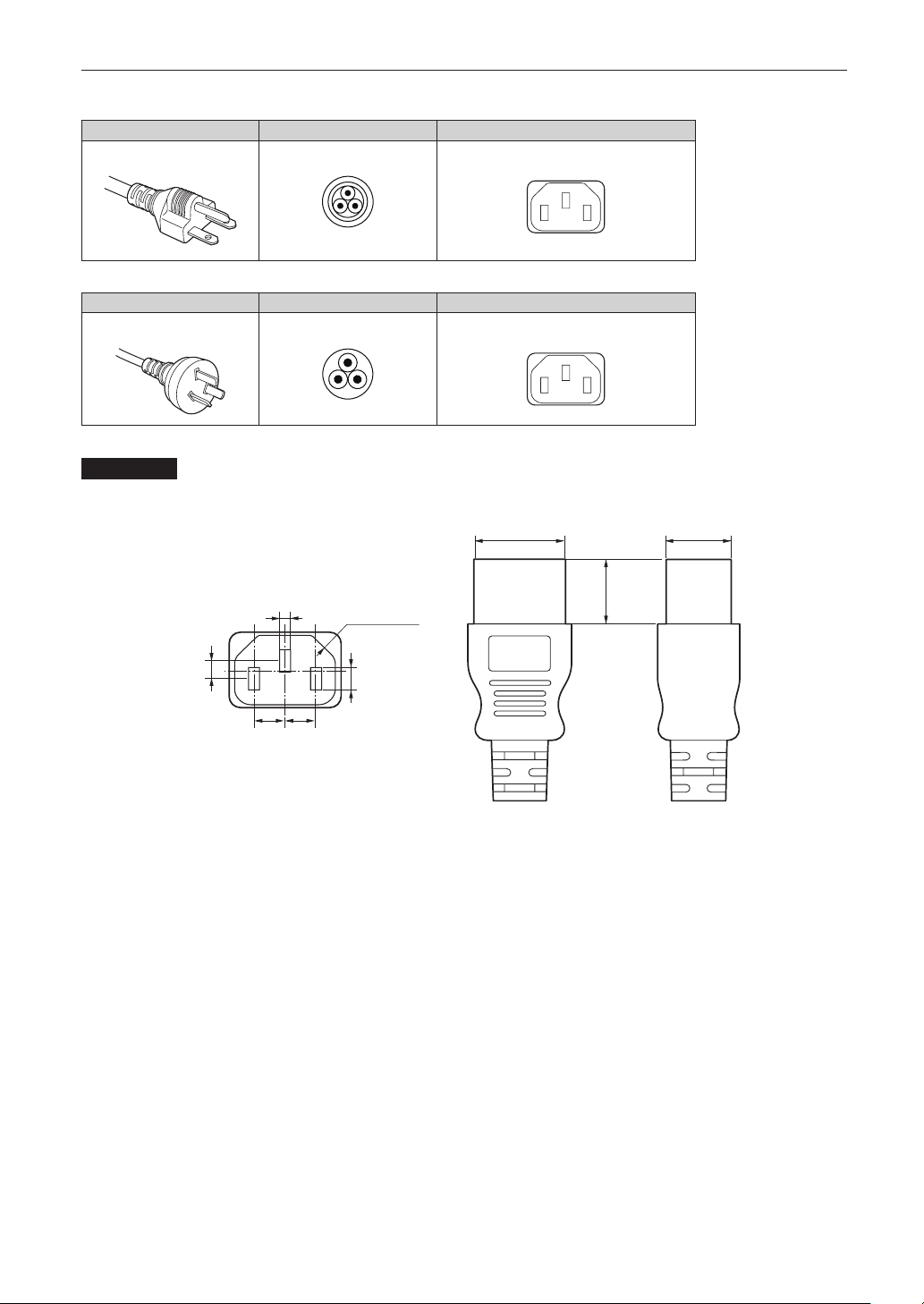
Setting Up Your Projector
Japan
Plug Cable Connector
JIS C 8303
HVCTF 3 x 1.25mm
China
Plug Cable Connector
GB2099
RVV 300/500 GB17465.1
Connector
Dimensions of the connector of the power cable are shown below.
2
IEC60320 C13
28
+0
-
0.9
20
+0
-
0.7
0
+0.5
-
4
Unit: mm
2.5
+0.5
-
0
4-R3.5
(Min)
20
(Min)
0
+0.5
-
5
+0.5
+0.5
7
7
-
0
-
0
60
Page 61

Setting Up Your Projector
HINWEIS
2-4.
Es wird kein Netzkabel für Anschluss C2 mit dem Projektor geliefert. Nehmen Sie auf „2-4-1. Netzstrom-Spezifikationen“ (Seite 62)
Bezug, und beschaffen Sie das notwendige Netzkabel.
Lesen Sie diesen Abschnitt vor dem Herstellen der Verbindungen sorgfältig durch, und schließen Sie die Kabel anhand der
ordnungsgemäßen Verfahren an. Falsche Handhabung kann zu schweren oder sogar tödlichen Verletzungen durch Brand oder
einen elektrischen Schlag führen.
• Bevor Sie das Netzkabel anschließen, prüfen Sie, ob die Hauptstromschalter des Projektors ausgeschaltet ist. Stellen Sie die
Verbindungen bei ausgeschaltetem Netzstrom her.
• Erden Sie das Gerät, um die Sicherheit zu gewährleisten. Verwenden Sie ein Netzkabel, das die Normen und Netzspannung
des Landes, in dem der Projektor verwendet wird, erfüllt (Seite 62), und schließen Sie das Gerät stets an Erde an. Wenn keine
Erde angeschlossen wird, kann es zu elektrischen Schlägen kommen.
• Führen Sie die Netzkabelstecker beim Anschließen bis zum Anschlag in den Netzeingang und die Netzsteckdose ein. Sitzt
der Netzstecker nicht fest in der Netzsteckdose, kann Wärme im Steckerbereich erzeugt werden, die zu Verbrennungen und
Unfällen führen kann.
• Um eine Trennung des Netzsteckers vom Projektor zu verhindern, fixieren Sie das Netzkabel, indem Sie den mit diesem Gerät
gelieferten Netzkabelstopper verwenden. Die Verwendung des Netzkabelstoppers siehe 62.
Auswahl des Netzkabels für Anschluss C2 (Deutsch)
WARNUNG
ACHTUNG
• Installieren Sie die Steckdose nahe beim Projektor, so dass Sie die Stromzufuhr unterbrechen konnen, indem Sie
das Netzkabel abtrennen.
• Vergewissern Sie sich, dass der Hauptstromschalter auf der Position [O] steht, bevor Sie das Netzkabel anschliesen
oder abziehen. Anderenfalls kann es zu einer Beschadigung des Projektors kommen.
• Verwenden Sie keine Dreiphasen-Stromversorgung. Anderenfalls kann es zu einer Funktionsstorung kommen.
61
Page 62
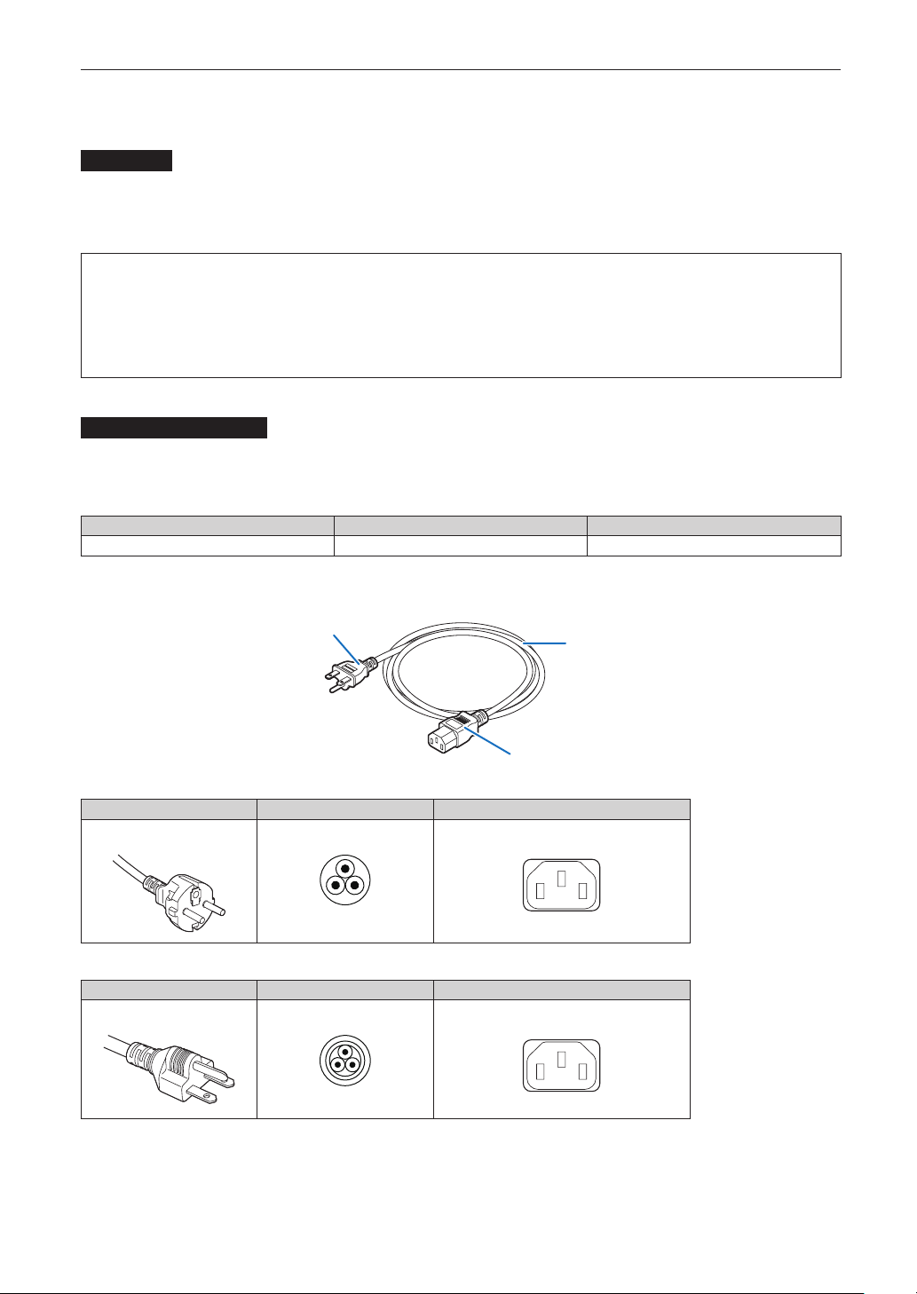
Setting Up Your Projector
2-4-1. Netzstrom-Spezikationen
Netzkabel
Der Projektor ist mit einem C19-Steckverbinder gemäß IEC60320 zum Anschließen des Netzkabels ausgestattet. Sorgen Sie dafür,
dass die Netzkabel, die von den Steckverbindern am Projektor zum Netzanschluss führen, über die unten angegebenen Stromkapazitäten verfügen.
For C2 connection (when using two different power cables to supply the AC power to the projector and the light source
separately)
- AC100– 240 V single phase, 50/60Hz
(Power supply to the projector)
- AC200– 240 V single phase, 50/60Hz
(Power supply to the light source)
NetzkabelfürdenProjektor
Der Projektor ist mit einem C14-Eingang gemäß IEC60320 zum Anschließen des Netzkabels ausgestattet.Verwenden Sie einen
IEC60320 C13-kompatiblen Netzkabelanschluss und sorgen Sie dafür, dass der Anschluss über die unten angegebene Stromkapazität verfügt.
Netzspannung Projektor-Eingangsstrom Netzkabel-Stromkapazität
100 - 240V Wechselstrom 4,9 A
10 A oder höher
Furthermore, use plugs, cables, and connectors that are suitable for the regulations of the country of installation, as shown in the
following table.
Stecker
Kabel
Steckverbinder
Deutschland
CEE 7
Stecker Kabel Steckverbinder
H05VV-F 3x1mm
2
IEC60320 C13
USA
Stecker Kabel Steckverbinder
NEMA 6-15P
SJT 3 x AWG 16 IEC60320 C13
62
Page 63
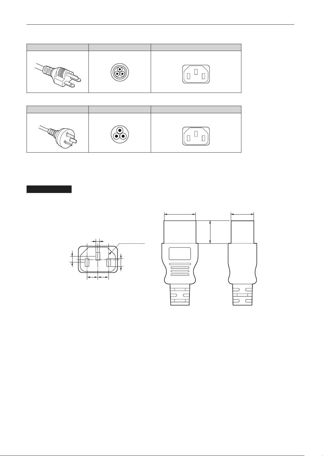
Japan
JIS C 8303
Stecker Kabel Steckverbinder
HVCTF 3 x 1.25mm
2
IEC60320 C13
China
Stecker Kabel Steckverbinder
GB2099
RVV 300/500 GB17465.1
Für Benutzer in UK
Verwenden Sie ein Netzteil mit BS-Zulassung und 10A-Sicherung.
Steckverbinder
Die Abmessungen des Netzkabels sind unten angegeben.
28
Setting Up Your Projector
+0
-
0.9
20
+0
-
0.7
0
+0.5
-
4
Einheit: mm
2.5
+0.5
-
0
4-R3.5
(Min)
20
(Min)
0
+0.5
-
5
+0.5
+0.5
7
7
-
0
-
0
63
Page 64
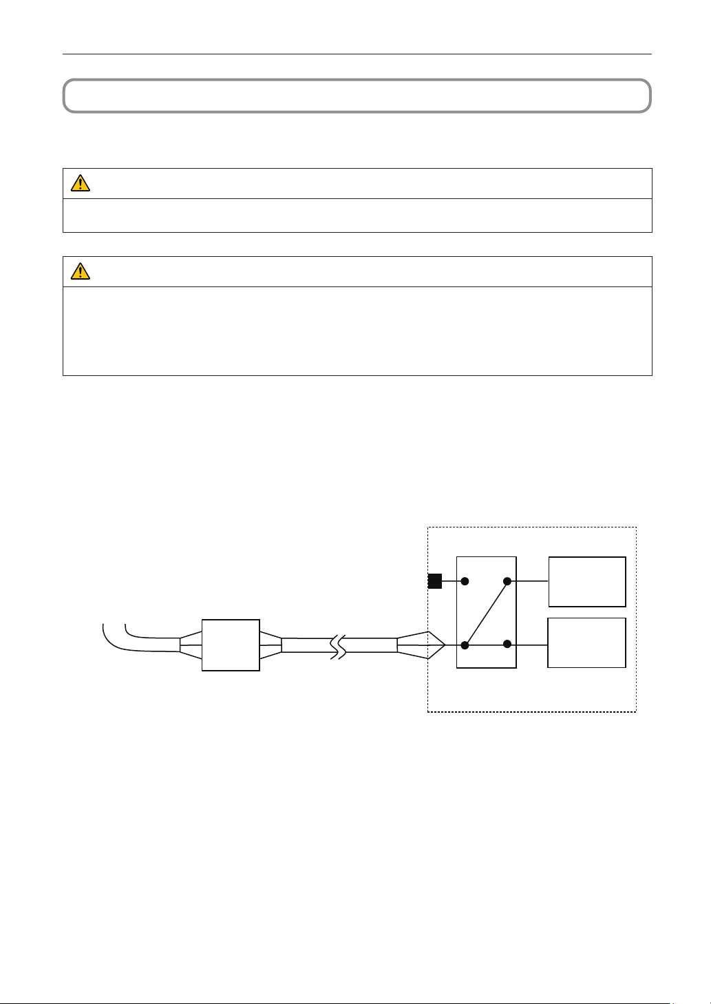
Setting Up Your Projector
2-5. Connecting the power cable (English)
Connect the power cable of the projector. The AC power cable is not attached as an accessory. Be sure to have professional
technicians do any power supply construction.
WARNING
Carefully read the contents described in this section before connection and connect the cables according to the proper procedure. Inappropriate handling may cause fatal, serious or other bodily injuries due to fire or electric shock.
CAUTION
• Make sure that the AC power supply is disconnected before carrying out the work of connecting the power supply cable.
• Be sure to follow the contents described in this section.
• Entrust a specialist to carry out the power supply work from the power supply equipment of the building to the place of projec-
tor installation.
• Be sure to ground the equipment to ensure safety. To avoid electric shock, request a professional to carry out the grounding
and related works. Make sure to ground the equipment before supply of the AC power.
2-5-1. Power supply construction specications
There are two different ways to connect the power cables, the C1 connection and the C2 connection.
•C1connection
AC power is provided to the projector power supply and the light power supply by a single cable.
AC power supply
equipment
Breaker
AC power supply cable
Input Selection
C1 connection
Projector
(Main unit)
Light power
supply unit
64
Page 65
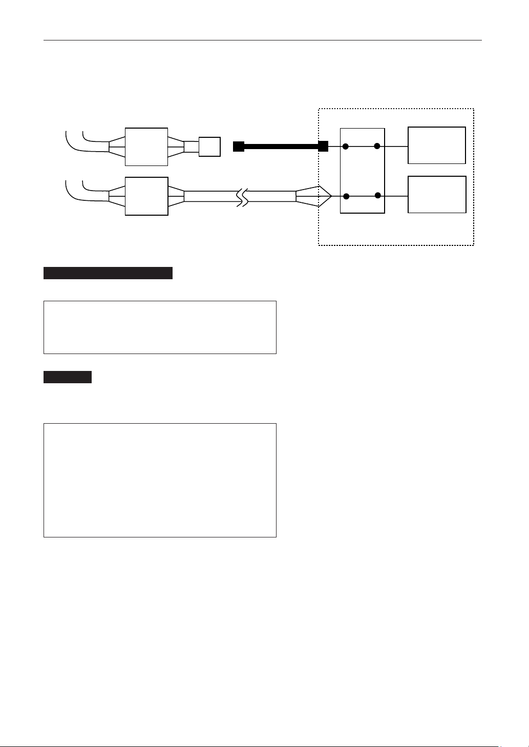
Setting Up Your Projector
•C2connection
AC power is provided to the projector power supply and the light power supply by separate cables.
C2 connection
AC power supply
equipment
AC power supply
equipment
Breaker
Breaker
Electric outlet
AC power supply cable
AC power supply
cable
Input Selection
Projector
(Main unit)
Light power
supply unit
ACpowersupplyequipment
Do not connect AC power supply voltages to the projector other than those indicated below.
When using with a C1 connection
•200 - 240 V AC, single phase, 50/60 Hz
When using with a C2 connection
•100 - 240 V AC, single phase, 50/60 Hz (projector power supply)
•200 - 240 V AC, single phase, 50/60 Hz (light power supply)
Breakers
When connecting the AC power supply from the power supply equipment of the building to the projector, be sure to connect it
through a breaker. The capacity of the breaker must be as indicated below.
When using with a C1 connection
•Power supply for projector + power supply for light
200V-240 V AC: Input current 40A
Inrush current 150A or higher @10msec
When using with a C2 connection
•Power supply for projector
100V-240 V AC: Input current 10A
Inrush current 60A or higher @10msec
•Power supply for light
200V-240 V AC: Input current 40A
Inrush current 150A or higher @10msec
65
Page 66

Setting Up Your Projector
InputSelection
The power supply connection method is configured by the wiring to the input selection. The configurations are as follows.
LN
C1
ConnectionC2Connection
ACpowersupplycable
• For the AC power cable, use a cable of thickness as appropriate for the installation country and made of copper as shown below.
• Use a round type UL-listed solderless terminal for the section connected to the main unit. In addition, when clamping this terminal
with the cable, use an UL listed tool.
CompatibleCablesandSolderlessTerminals
The specifications of the terminals for attaching the power cables are as follows.
L N
Power supply terminal L, N
Grounding terminal G
The size of the solderless terminal to use and the fastening torque of the screws varies depending on the type of terminal block.
Use the cable and solderless terminal that is suitable for the specific type of terminal block as shown in the following table. This
specifies the model name of the recommended solderless terminals. Use these parts or equivalent parts. If you are unable to use
the recommended solderless terminals, ensure that you use terminals of the dimensions shown in the following diagram.
66
Page 67

Setting Up Your Projector
WARNING
• The power supply unit handles large electrical currents. To maintain safety, use wires with the specifications as shown in the
following table, and affix to the terminals at the designated attachment torque.
• Always use solderless terminals with the dimensions as shown in the following diagram.
• The use of parts with dimensions other than as designated creates a risk of the AC power supply unit short circuiting due to
the terminal block generating heat and melting because the terminal block of the light power supply unit cannot be attached
correctly.
•PowersupplyterminalL,N(Black)
JIS IEC/EN UL CSA
Thickness of compatible wiring
(using solderless terminal)
Solderless terminal dimensions M5 x 10
Tightening torque 2.0 to 2.5N·m
Solderless terminal dimensions
14mm
2
Max 12.2
Max 5.8
14mm
2
Min 4.5
AWG6 or
AWG8
Min φ6.1
Min 1.0
-Max 2.0
AWG6 or
AWG8
Min 1.0
-Max 2.0
Solderless terminal recommended
part (J.S.T parts)
J.S.T: J.S.T. Manufacturing Co. Ltd.
Unit: mm
Model R8-5 When using AWG6: Model R14-5
When using AWG8: Model R8-5
67
Page 68

Setting Up Your Projector
•GroundterminalG(Green/Yellow)
JIS IEC/EN UL CSA
Thickness of compatible wiring
(using solderless terminal)
Solderless terminal dimensions M6 x 15
Tightening torque 3.5 to 5.0N·m
Solderless terminal dimensions
14mm
Unit: mm
2
Max 13
Max 11
14mm
2
Min 7.5
AWG6 or
AWG8
Min φ6.1
AWG6 or
AWG8
Min 1.0
-Max 2.0
Min 1.0
-Max 2.0
Solderless terminal recommended
part (J.S.T parts)
J.S.T: J.S.T. Manufacturing Co. Ltd.
Model 8-8NS When using AWG6: Model R14-6
When using AWG8: Model 8-8NS
68
Page 69

Setting Up Your Projector
1
2
Connectingthecable
In order to attach the power cable to the connector block, connect the wires using the following procedure such that the individual
wires cannot directly touch each other.
Remove the power cable sleeves from the terminals
to ensure that the sleeves are not pinched by the terminal attachment screw.
Pull back the sleeves from the terminal area before fastening the screw
to prevent the sleeves from being pinched.
Attach the sleeves after tightening the screw.
Tighten the fixing screw to the designated torque.
Use sleeves and secure the insulation to ensure that terminals do not touch
each other. If the cables are attached to the power supply terminal without
using sleeves, there is a risk of the terminals touching each other as shown
in the photograph on the right.
Sleeves
69
Page 70

Setting Up Your Projector
When connecting the cables to the ground terminal block, ensure that
parts other than the solderless terminal (such as cable wires and fittings)
are not pinched within the terminal fastening area.
When correctly fastened.
When the cable wire has become pinched due to using a solderless terminal with dimensions other than as designated.
70
Page 71

Setting Up Your Projector
1
2
3
2-5-2. Procedure for connecting the power cable (C1 connection)
Preparation: Phillips-head screwdriver (No. 2), service key (projector accessory)
WARNING
• Before connecting the power cable, make sure that the AC power supply is disconnected. Otherwise a fire or electric shock
may occur.
• High leakage current flows. Do NOT connect the power supply before grounding connection.
Remove the plate inlet.
Remove the plate inlet by loosening the fixing screws (at four points).
In Europe, replace it with the supplied φ35 plate inlet. Use the fixing screws that were used before the replacement of the
plate inlet.
Plate Inlet
Pass the power cable through the cable hole of the plate.
If you use the supplied φ35 plate inlet, pass the power cable through a commercially available cable stopper and then
insert it into the cable hole.
Cable stopper
Remove the terminal cover of the power supply terminals.
Remove the terminal cover by pulling it upward.
71
Page 72

Setting Up Your Projector
4
5
6
Insert the L/N lines of the AC power cable into the connection terminals, and tighten the
screws.
Insert the crimping terminals of the AC power cable into the retaining holes of the connection terminals, and tighten the
screws with the Phillips-head screwdriver.
WARNING
Securely screw the AC power cable to the connection terminals. Also, after tightening the screws, make sure that all the power
cable lines are securely screwed. A failure to do this could result in an accident causing death, injury, etc.
Put the terminal cover on the power supply terminals.
Follow the reverse procedure to removal of the terminal cover.
Insert the grounding cable into the grounding terminal, and screw it.
Insert the crimping terminal of the grounding cable into the retaining hole of the connection terminal, and tighten the screw
with the Phillips-head screwdriver.
WARNING
Securely screw the grounding cable to the connection terminal. Also, after tightening the screw, make sure that the screw is
securely tightened. A failure to do this could result in an accident causing death, injury, etc.
72
Page 73
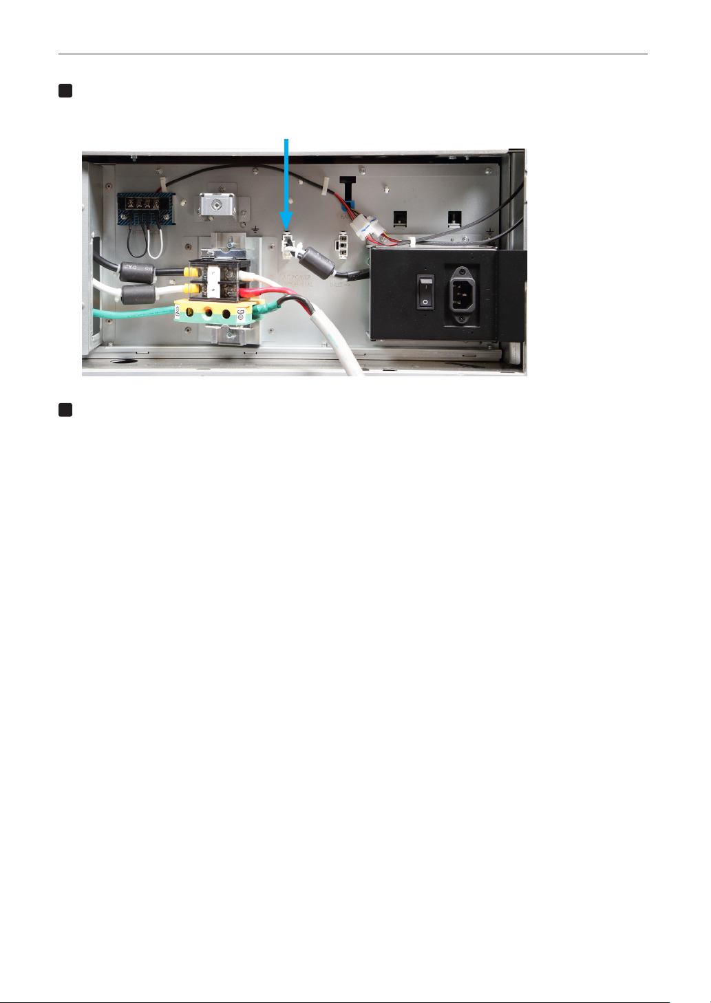
7
Configure the power supply for C1 connection.
8
For C1 connection, connect the left-side connector.
Connect the C1 connector.
Fix the plate inlet with the xing screws (at four points).
In Europe, fix the supplied φ35 plate inlet.
Setting Up Your Projector
73
Page 74

Setting Up Your Projector
1
2
3
2-5-3. Procedure for connecting the power cable (C2 connection)
Preparation: Phillips-head screwdriver (No. 2), service key (projector accessory)
WARNING
Before connecting the power cable, make sure that the AC power supply is disconnected. Otherwise a fire or electric shock may
occur.
Follow steps 1 to 7 in “2-5-2. Procedure for connecting the power cable (C1 connection)”
(page 71).
Configure the power supply for C2 connection.
For C2 connection, connect the right-side connector.
Connect the C2 connector.
Fix the plate inlet with the fixing screws (at four points).
74
Page 75

Setting Up Your Projector
4
5
Connect the AC power supply cable to the AC input of the projector.
Insert the plug firmly all the way into the AC input.
AC input
Make sure you insert the plug rmly.
Connect the power plug to the electrical outlet.
This completes the connection of the AC power supply cable.
75
Page 76

Setting Up Your Projector
NOTE
1
2
Attachingthepowercablestopper
To prevent the power cable from accidently removing from the AC IN of the projector, attach the supplied power cable stopper to
clamp the power cable.
CAUTION
• To prevent the power cable from coming loose, make sure that all the prongs of the power cable are fully inserted into the AC
IN terminal of the projector before using the power cable stopper to fix the power cable. A loose contact of the power cable
may cause a fire or electric shock.
• Do not bundle the power cable. Doing this could cause heat or a fire.
• Do not clamp the power cable with other cables. Doing so can generate noise, which can affect adversely the signal
cable.
• Once the power cable stopper is attached, it cannot be removed.
Set the clamper band to the power cable side, and insert the end of band of the power cable
stopper into the slot next to the AC IN on the terminal panel.
Attach the power cable stopper to the other side in the same way.
Pass each band through the slits in the power cable stopper.
Pass the bands through them so that the power cable will be sandwiched from left and right.
band
76
Page 77

3
Slide the clamper to the hilt of the power cable.
4
Pulling the knob in the arrow direction allows you to adjust the clamper position.
Once the clamper position is adjusted, release the knob to lock the clamper.
knob
Pull the band to hold the power cable.
Pulling the knob in the arrow direction allows you to adjust the band position.
Pull the top and bottom bands by keeping their balance.
Once the band position is adjusted, release the knob to lock.
Setting Up Your Projector
knob
This completes the attachment of the power cable stopper.
knob
77
Page 78
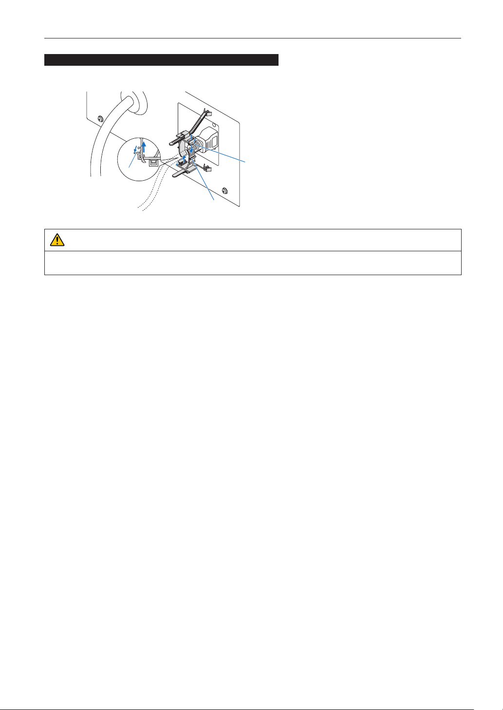
Setting Up Your Projector
Removingthepowercablefromthepowercablestopper
Pull the knob of the clamper and loosen the band.
knob
knob
band
CAUTION
The projector may become hot temporarily when the power is turned off or if the AC power is disconnected while the projector
is projecting. Take care when handling the projector.
78
Page 79

Setting Up Your Projector
2-6. Anschließen des Netzkabels (Deutsch)
Schließen Sie das Netzkabel des Projektors an. Das Netzkabel ist nicht abziehbar sondern fest mit dem Gerät verbunden. Lassen
Sie die Installation einer Netzstromversorgung unbedingt nur von professionellen Elektrikern durchführen.
WARNUNG
Lesen Sie diesen Abschnitt sorgfältig durch, bevor Sie die Kabel anschließen, und befolgen Sie beim Anschließen der Kabel die
entsprechenden Anweisungen. Durch unsachgemäße Handhabung kann es infolge von Bränden oder elektrischen Schlägen zu
tödlichen, schweren oder anderen Verletzungen kommen.
ACHTUNG
• Vergewissern Sie sich, dass das Gerät von der Stromversorgung getrennt ist, bevor Sie das Netzkabel anschließen.
• Befolgen Sie auf jeden Fall die Anweisungen in diesem Abschnitt.
• Beauftragen Sie einen Fachmann mit der Installation die Stromzufuhr von der Stromversorgungsanlage des Gebäudes zum
Aufstellort des Projektors.
• Erden Sie das Gerät, um die Sicherheit zu gewährleisten. Um elektrische Schläge zu vermeiden beauftragen Sie einen Fachmann mit der Erdung und den damit verbundenen Arbeiten. Stellen Sie sicher, dass das Gerät geerdet ist, bevor Sie Strom
zuführen.
2-6-1. Technische Daten zum Netzanschluss
Die Netzkabel können auf zweierlei Weise angeschlossen werden: zum einen über Anschluss C1 und zum anderen über Anschluss
C2.
•AnschlussC1
Die Stromversorgung zu den Netzteilen des Projektors und der Lichtquelle wird über ein einzelnes Kabel zugeführt.
Anschluss C1
Projektor
Netzstromversorgung
Sicherung
Netzstromkabel
Eingabe Auswahl
(Grundgerät)
Licht Netzteil
79
Page 80

Setting Up Your Projector
•AnschlussC2
Die Stromversorgung zu den Netzteilen des Projektors und der Lichtquelle wird über getrennte Kabel zugeführt.
Anschluss C2
Netzstromversorgung
Netzstrom-
versorgung
Sicherung
Sicherung
Elektrosteckdos
Netzstromkabel
Netzstromkabel
Projektor
(Grundgerät)
Licht Netzteil
Eingabe Auswahl
Wechselstromversorgung
Betreiben Sie den Projektor nur mit den unten angegebenen Netzspannungen.
Bei Verwendung von Anschluss C1
•200 – 240 V AC, einphasig, 50/60 Hz
Bei Verwendung von Anschluss C2
•100 – 240 V AC, einphasig, 50/60 Hz (Stromversorgung des Projektors)
•200 – 240 V AC, einphasig, 50/60 Hz (Stromversorgung der Lichtquelle)
Sicherungen
When connecting the AC power supply from the power supply equipment of the building to the projector, be sure to connect it
through a breaker. The capacity of the breaker must be as indicated below.
Bei Verwendung von Anschluss C1
•Stromversorgung des Projektors + Stromversorgung der
200V-240 V AC: Eingangsstrom 40A
Einschaltstrom 150A oder höher @10msec
Bei Verwendung von Anschluss C2
•Stromversorgung des Projektors
100V-240 V AC: Eingangsstrom 10A
Einschaltstrom 60A oder höher @10msec
•Stromversorgung der Lichtquelle
200V-240 V AC: Eingangsstrom 40A
Einschaltstrom 150A oder höher @10msec
Lichtquelle
80
Page 81

Setting Up Your Projector
EingabeAuswahl
Die Netzanschluss Methode wird durch die Schaltung der Eingabe Auswahl festgelegt. Die Konfigurationsmöglichkeiten sind im
Folgenden aufgeführt.
Anschluss C1 Anschluss C2
LN
C1
ConnectionC2Connection
Netzkabel
• Verwenden Sie als Netzkabel ein Kabel mit einer Kabelader aus Kupfer und einem Leiterquerschnitt, der den Vorgaben des
jeweiligen Landes entspricht (siehe folgende Abbildung).
• Verwenden Sie eine runde lötfreie Anschlussklemme mit dem UL Listing-Prüfzeichen für den an der Haupteinheit angeschlossenen Kabelabschnitt. Verwenden Sie darüber hinaus bei der Klemmung dieser Anschlussklemme ein Werkzeug mit dem UL
Listing-Prüfzeichen.
KompatibleKabelundlötfreieAnschlussklemmen
Die technischen Daten für die Anschlussklemmen zum Befestigen der Netzkabel sind im Folgenden aufgeführt.
L N
Netzklemme L, N
Erdklemme G
Die Größe der zu verwendenden lötfreien Anschlussklemme und das Anzugsmoment der Schrauben hängen von der Art des Klemmenblocks ab. Verwenden Sie das Kabel und die lötfreie Anschlussklemme, die jeweils für den entsprechenden Klemmenblock
geeignet sind (siehe folgende Tabelle). In dieser Tabelle sind die Modellnamen der empfohlenen lötfreien Anschlussklemmen angegeben. Verwenden Sie die angegebenen oder gleichwertige Bauteile. Wenn Sie die empfohlenen lötfreien Anschlussklemmen nicht
verwenden können, stellen Sie sicher, dass Sie Anschlussklemmen verwenden, deren Abmessungen den Angaben in der folgenden
Tabelle entsprechen.
81
Page 82
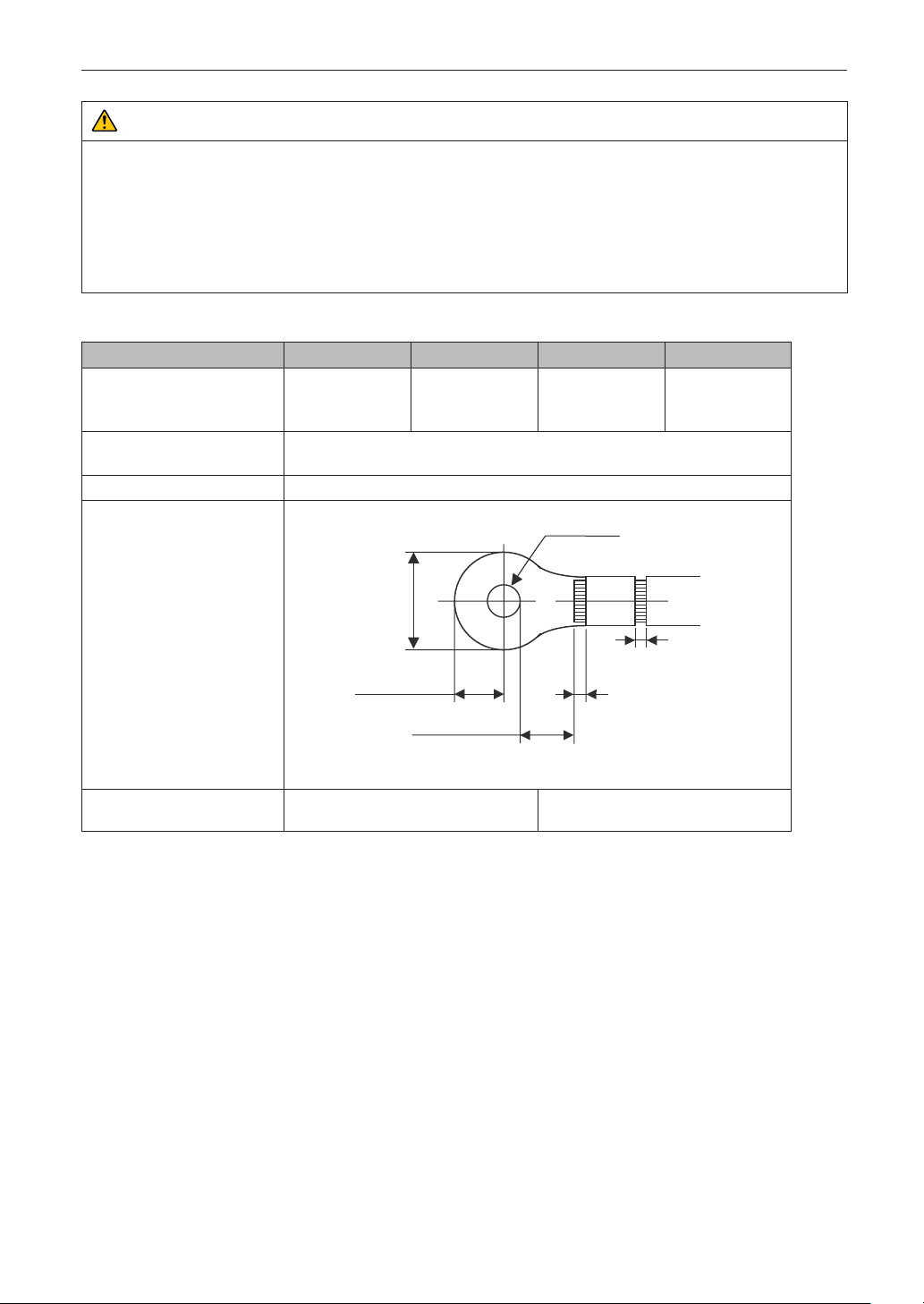
Setting Up Your Projector
WARNUNG
• Das Netzteil verarbeitet hohe elektrische Ströme. Verwenden Sie zur Gewährleistung der Sicherheit Kabeladern entsprechend
den in der folgenden Tabelle aufgeführten Vorgaben, und befestigen Sie die Anschlussklemmen am angegebenen
Klemmenblock.
• Verwenden Sie immer lötfreie Anschlussklemmen, deren Abmessungen den Angaben in der folgenden Abbildung
entsprechen.
• Die Verwendung von Bauteilen mit abweichenden Abmessungen birgt die Gefahr eines Kurzschlusses des Netzteils aufgrund
von Hitzeentwicklung und Schmelzen des Klemmenblocks, da der Klemmenblock für die Stromversorgung der Lichtquelle
nicht ordnungsgemäß angebracht werden kann.
•NetzklemmeL,N(Schwarz)
JIS IEC/EN UL CSA
Leiterquerschnitt kompatibler
Kabel (bei Verwendung lötfreier
Anschlussklemmen)
Abmessungen lötfreier
Anschlussklemmen
Anzugsmoment 2,0 bis 2,5 N·m
Abmessungen lötfreier
Anschlussklemmen
14mm
M5 x 10
2
14mm
2
AWG6 oder
AWG8
Min φ6.1
AWG6 oder
AWG8
Empfohlene Modelle für lötfreie
Anschlussklemmen (J.S.T-Teile)
J.S.T: J.S.T. Manufacturing Co. Ltd.
Max 12.2
Max 5.8
Min 4.5
Unit: mm
Modell R8-5 Bei AWG6: Modell R14-5
Bei AWG8: Modell R8-5
Min 1.0
-Max 2.0
Min 1.0
-Max 2.0
82
Page 83
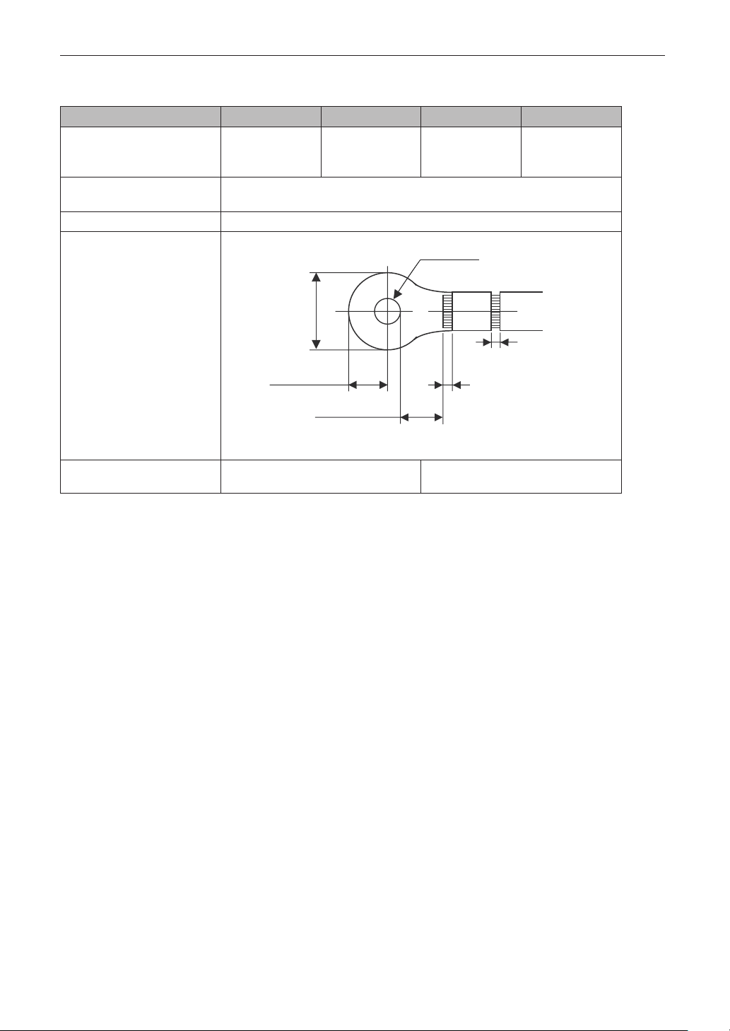
•ErdungsklemmeG(Grün/Gelb)
JIS IEC/EN UL CSA
Leiterquerschnitt kompatibler
Kabel (bei Verwendung lötfreier
Anschlussklemmen)
Abmessungen lötfreier
Anschlussklemmen
Anzugsmoment 3,5 bis 5,0 N·m
Abmessungen lötfreier
Anschlussklemmen
2
14mm
M6 x 15
Unit: mm
Max 13
Max 11
14mm
2
Min 7.5
AWG6 bis
AWG8
Min φ6.1
Setting Up Your Projector
AWG6 oder
AWG8
Min 1.0
-Max 2.0
Min 1.0
-Max 2.0
Empfohlene Modelle für lötfreie
Anschlussklemmen (J.S.T-Teile)
J.S.T: J.S.T. Manufacturing Co. Ltd.
Modell 8-8NS Bei AWG6: Modell R14-6
Bei AWG8: Modell 8-8NS
83
Page 84

Setting Up Your Projector
1
2
AnschließendesKabels
Schließen Sie zum Befestigen des Netzkabels am Klemmenblock die Drähte entsprechend den folgenden Anweisungen an, sodass
sich die einzelnen Drähte nicht direkt berühren können.
Ziehen Sie die Kabelmanschetten der Netzkabel von
den Anschlussklemmen zurück, um sicherzustellen,
dass diese nicht von der Schraube der Anschlussklemme eingeklemmt werden.
Ziehen Sie die Kabelmanschette von der Anschlussklemme zurück,
bevor Sie die Schraube anziehen, damit die Kabelmanschette nicht eingeklemmt wird.
Schieben Sie die Manschetten nach dem Anziehen der
Schraube wieder an ihre richtige Position.
Ziehen Sie die Befestigungsschraube mit dem angegebenen Drehmoment an.
Verwenden Sie Kabelmanschetten und fixieren Sie das Isolationsmaterial,
damit sich die Anschlussklemmen nicht berühren. Wenn die Kabel ohne
Kabelmanschetten an der Netzklemme befestigt werden, besteht die Gefahr,
dass sich die Anschlussklemmen wie in der Abbildung rechts berühren.
Manschetten
84
Page 85
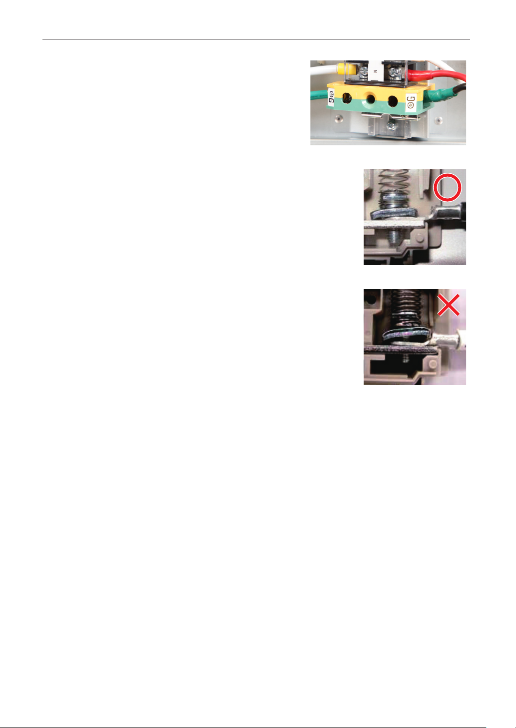
Achten Sie beim Anschließen der Kabel an die Masseanschlussklemme
darauf, dass keine anderen Teile als der Quetschkabelschuh (z. B. Kabeladern undVerschraubungen) in der Klemmenbefestigung eingeklemmt
werden.
Richtig befestigt.
Kabeldraht ist verkantet, da eine lötfreie Anschlussklemme mit Abmessungen verwendet wurde, die nicht den Vorgaben entsprechen.
Setting Up Your Projector
85
Page 86

Setting Up Your Projector
1
2
2-6-2. Anschluss des Stromkabels (Anschluss C1)
Vorbereitung: Kreuzschraubenzieher (Nr. 2), Serviceschlüssel (Projektorzubehör)
WARNUNG
• Stellen Sie sicher, dass die Stromversorgung unterbrochen ist, bevor Sie das Stromkabel anschließen. Es besteht Brand- und
Stromschlaggefahr.
• Es entsteht viel Kriechstrom. Stellen Sie unbedingt sicher, die Stromversorgung nur anzuschließen, nachdem die Erdung
angeschlossen ist.
Entfernen Sie die Platte Inlet.
Remove the plate inlet by loosening the fixing screws (at four points).
In Europe, replace it with the supplied φ35 plate inlet. Use the fixing screws that were used before the replacement of the
plate inlet.
Platte Inlet
Vergewissern Sie sich, dass das Stromkabel durch die Kabelöffnung passieren kann, und zie-
hen Sie das Stromkabel durch die Kabelöffnung der Platte Inlet.
Wenn Sie die beigefügte 35mm-Platte Inlet benutzen, sichern Sie das Stromkabel mit einem handelsüblichen Kabelfixierer
in der Kabelöffnung.
Kabelxierer
86
Page 87

Setting Up Your Projector
3
4
5
6
Entfernen Sie den Deckel der Strombuchse.
Ziehen Sie dazu den Deckel zu sich hin und heben Sie ihn nach oben.
Stecken Sie die L-Leitung und N-Leitung des Stromkabels in die Anschlussbuchse und schrau-
ben Sie sie fest.
Stecken Sie den Crimpanschluss des Stromkabels in die Öffnung der Anschlussbuchse und schließen Sie die Schrauben
mit einem Kreuzschraubenzieher.
WARNUNG
Verschrauben Sie das Stromkabel gut in der Anschlussbuchse. Vergewissern Sie sich nach dem Schließen der Schrauben, dass
alle Stromkabel gut verschraubt sind. Wenn die Schrauben nicht richtig geschlossen sind, können Tod und schwere Verletzungen die Folge sein.
Befestigen Sie den Deckel der Strombuchse.
Gehen Sie dabei in umgekehrter Reihenfolge zum Entfernen vor.
Stecken Sie das Erdungskabel in die Anschlussbuchse und schrauben Sie es fest.
Stecken Sie den Crimpanschluss des Erdungskabels in die Öffnung der Anschlussbuchse, und schließen Sie die Schrauben mit einem Kreuzschraubenzieher.
WARNUNG
Verschrauben Sie das Erdungskabel gut in der Anschlussbuchse. Vergewissern Sie sich nach dem Schließen der Schrauben,
dass das Erdungskabel gut verschraubt ist. Wenn die Schrauben nicht richtig geschlossen sind, können Tod und schwere
Verletzungen die Folge sein.
87
Page 88

Setting Up Your Projector
7
8
Configure the power supply for C1 connection.
For C1 connection, connect the left-side connector.
Connect the C1 connector.
Fix the plate inlet with the xing screws (at four points).
EU-Region: Befestigen Sie die als Zubehör beigefügte 35mm-Platte Inlet.
88
Page 89
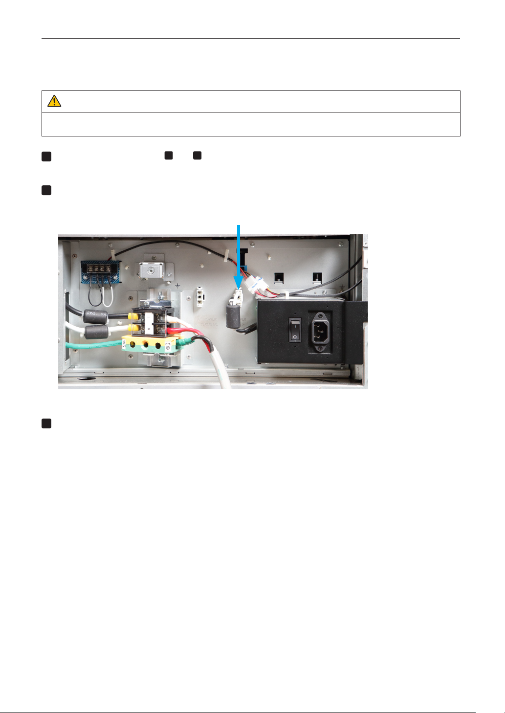
Setting Up Your Projector
1
2
3
2-6-3. Anschluss des Stromkabels (Anschluss C2)
Vorbereitung: Kreuzschraubenzieher (Nr. 2), Serviceschlüssel (Projektorzubehör)
WARNUNG
Stellen Sie sicher, dass die Stromversorgung unterbrochen ist, bevor Sie das Stromkabel anschließen. Es besteht Brand- und
Stromschlaggefahr.
Führen Sie die Schritte 1 bis 7 unter „2-6-2. Anschluss des Stromkabels (Anschluss C1)“
(Seite 86) aus.
Configure the power supply for C2 connection.
For C2 connection, connect the right-side connector.
Connect the C2 connector.
Fix the plate inlet with the fixing screws (at four points).
89
Page 90

Setting Up Your Projector
4
5
Connect the AC power supply cable to the AC input of the projector.
Insert the plug firmly all the way into the AC input.
AC input
Make sure you insert the plug rmly.
Connect the power plug to the electrical outlet.
Dadurch ist der Anschluss des Netzkabels abgeschlossen.
90
Page 91

Setting Up Your Projector
NOTE
1
2
AnbringendesNetzkabelstoppers
To prevent the power cable from accidently removing from the AC IN of the projector, attach the supplied power cable stopper to
clamp the power cable.
CAUTION
• To prevent the power cable from coming loose, make sure that all the prongs of the power cable are fully inserted into the AC
IN terminal of the projector before using the power cable stopper to fix the power cable. A loose contact of the power cable
may cause a fire or electric shock.
• Do not bundle the power cable. Doing this could cause heat or a fire.
• Do not clamp the power cable with other cables. Doing so can generate noise, which can affect adversely the signal
cable.
• Once the power cable stopper is attached, it cannot be removed.
Set the clamper band to the power cable side, and insert the end of band of the power cable
stopper into the slot next to the AC IN on the terminal panel.
Attach the power cable stopper to the other side in the same way.
Pass each band through the slits in the power cable stopper.
Pass the bands through them so that the power cable will be sandwiched from left and right.
band
91
Page 92
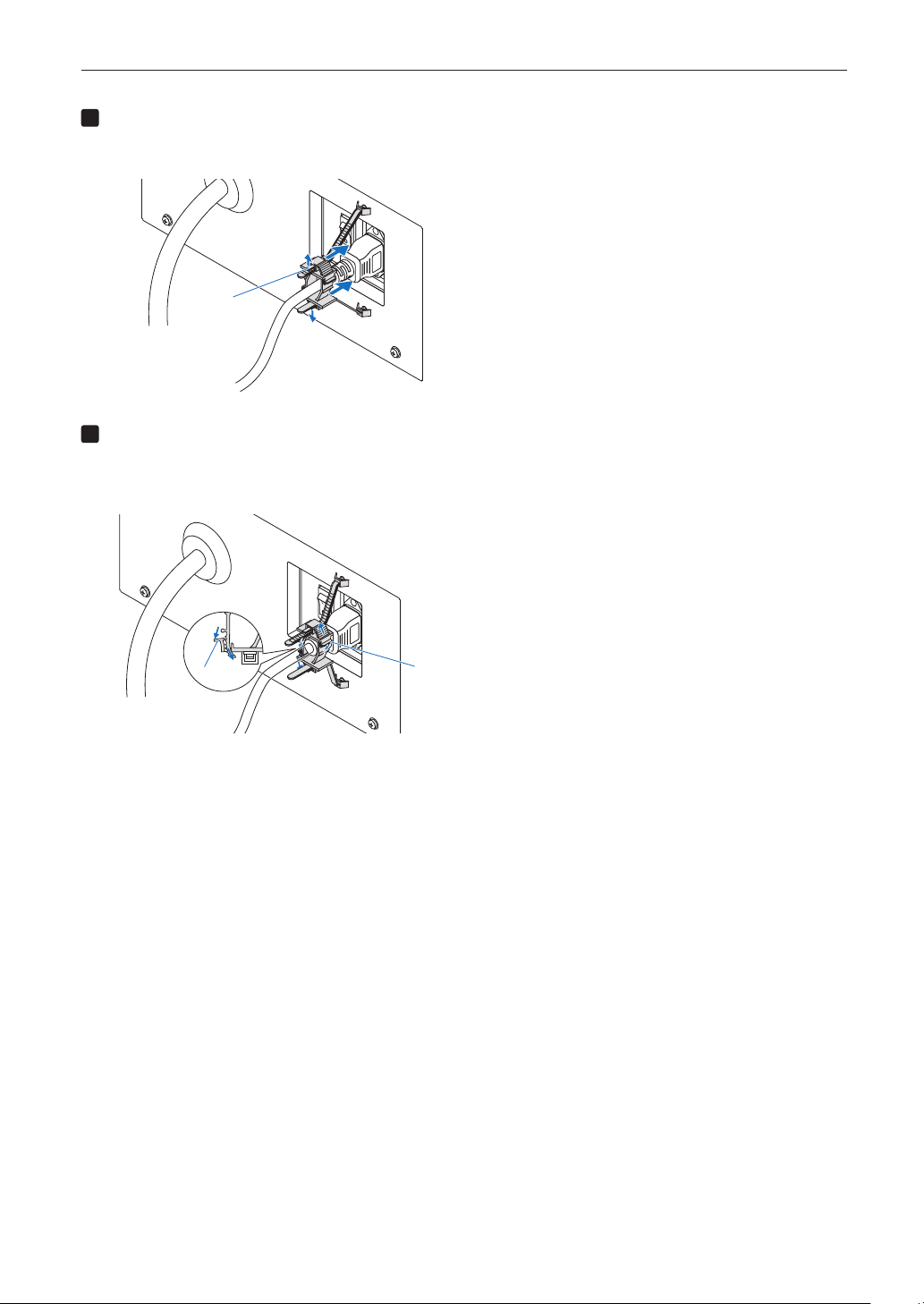
Setting Up Your Projector
3
4
Slide the clamper to the hilt of the power cable.
Pulling the knob in the arrow direction allows you to adjust the clamper position.
Once the clamper position is adjusted, release the knob to lock the clamper.
knob
Pull the band to hold the power cable.
Pulling the knob in the arrow direction allows you to adjust the band position.
Pull the top and bottom bands by keeping their balance.
Once the band position is adjusted, release the knob to lock.
knob
This completes the attachment of the power cable stopper.
knob
92
Page 93

Setting Up Your Projector
Removingthepowercablefromthepowercablestopper
Pull the knob of the clamper and loosen the band.
knob
knob
band
CAUTION
The projector may become hot temporarily when the power is turned off or if the AC power is disconnected while the projector
is projecting. Take care when handling the projector.
93
Page 94

Setting Up Your Projector
NOTE
2-7. Mounting the Lens Unit
The lens units that can be attached to this projector are shown in the following table.
MODEL Magnifying
NC-60LS12Z 1.20 - 1.81
NC-60LS14Z 1.40 - 2.05
NC-60LS16Z 1.59 - 2.53
NC-60LS19Z 1.90 - 3.25
NC-60LS24Z 2.40 - 3.90
NC-60LS39Z 3.90 - 6.52
• The other NEC optional lenses are not available on this model.
• The projector and lenses are made of precision parts. Do not subject them to shock or excessive forces.
• Remove the lens unit when moving the projector. If not, the lens could be subject to shock while the projector is
being moved, damaging the lens and the lens shift mechanism.
• When removing or installing the lens unit, return the position of the lens to the center before turning off the power
to the projector. If the position of the lens is not returned to center, the front cover will interfere with the lens and the
cover cannot be removed or installed.
• When installing or removing the lens unit, first confirm that the main power switch to the projector is off, and then
disconnect the AC power supply. After the AC power supply has been disconnected, allow the projector to sufficiently cool before starting this work.
• Never touch the lens surface while the projector is operating.
• Be very careful not to let dirt, grease, etc., on the lens surface and not to scratch the lens surface.
• Perform these operations on a flat surface over a piece of cloth, etc., to prevent the lens from getting scratched.
• When leaving the lens off the projector for long periods of time, mount the lens mount cap on the projector to
prevent dust or dirt from getting inside.
• If you remove the lens cover, a tamper event is detected by the tamper detection circuit. When you start the projec-
NOTE
tor after attaching the cover, the following error message is displayed on the LCD screen of the projector main unit.
- “IMB: Service Door Tamper” (When NP-90MS01 mounted)
• Encrypted contents cannot be displayed while an error message is being displayed. Refer to “3-2. Recovering from
Tamper Errors” (page 103) for details on how to clear the error message.
94
Page 95

Setting Up Your Projector
1
3
Thischapterillustratesthefactorydefaultsettings.
2-7-1. Part names of Lens Mount
Lens unit fall prevention metal tting Lens control connector
Release lever
Lens mount capLens stopper
Remove the lens cover.
Forremovingthelenscover,referto“1-5-1.RemovingandMountingtheLensCover”onpage51.
2
Remove the lens mount cap.
(1) Rotate the release lever clockwise in the upward
direction.
The lens stopper will be released.
(2) Rotate the lens mount cap counterclockwise
and remove it.
Keep the lens mount cap in a safe place for later
use.
Remove the lens cap from the rear end
of the lens unit.
Keepthelenscapinasafeplaceforlateruse.
(1)
(2)
95
Page 96
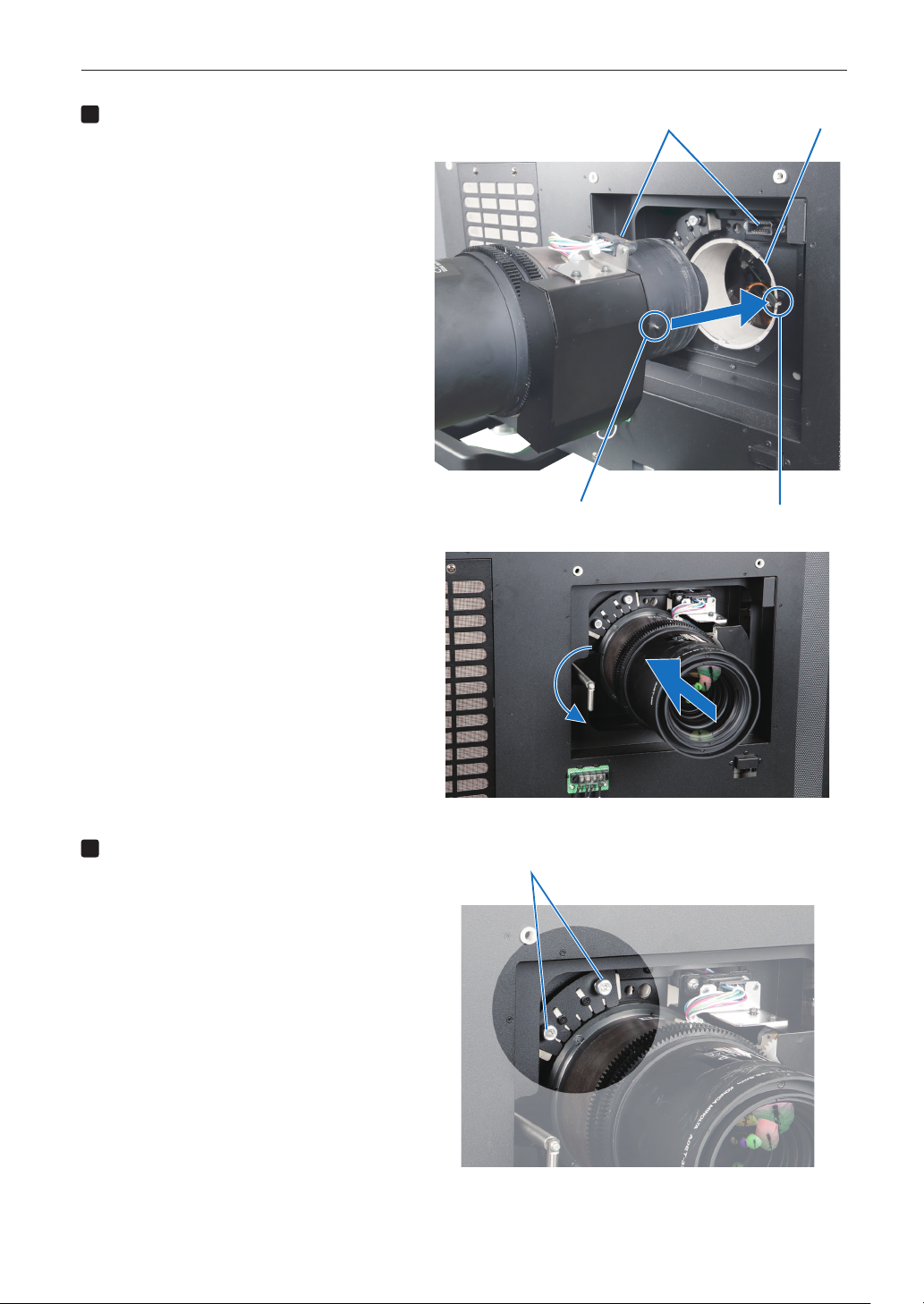
Setting Up Your Projector
4
5
Mount the lens unit to the lens mount
of the projector.
(1) Align the guide slit of the lens mount with the
position of the pin on the lens unit.
(2) Slowly insert the lens unit into the lens mount.
While doing this, try to connect the lens unit’s
connector with the lens mount’s lens control
connector.
(3) Rotate the release lever counterclockwise in the
downward direction to lock the lens unit.
Lens control connector
Pin
Lens mount
Guide slit
Use the fall prevention metal fitting to
Loosen these screws.
fix the lens unit.
(1) Tighten the screws (at two points).
96
Page 97

(2) Slide the fall prevention metal fitting downward.
6
(3) Tighten the two screws that were loosened.
Setting Up Your Projector
Attach the lens cover.
For details on attaching the lens cover, refer to
“1-4-1.RemovingandMountingtheLensCover”.
Makesurethereleaseleverissetinthedownward
direction.If it is set in the upward direction,the
lenscovercannotbeattached.
This completes the installation of the lens unit.
Removalisdoneinreverseorderofinstallation.
97
Page 98

Setting Up Your Projector
2-8. Mounting the Option Board
This section describes the procedure of mounting the media block. The following option board can be mounted to the slot of the
projector.
Name Slot
IMB NP-90MS01
NP-90MS02
Preparation:
Phillips-head screwdriver (No.2), service key (attached goods).
• Step1
Remove Side Panel from the Projector (See page 53)
• Step2
Mount the Option Board to the Projector (See this page)
• Step3
Mount the Side Panel to the Projector (See page 53)
• Step4
Clear the Tamper Error (See page 103)
Setting up the Projector (See page 100)
• If you remove the side panel, a tamper event is detected by the tamper detection circuit. When you start the projec-
NOTE
tor after attaching the cover, the following error message is displayed on the LCD screen of the projector main unit.
- “IMB: Service Door Tamper”
• If you remove the blocking panel or option board from a slot, a tamper event is detected by the tamper detection
circuit. When you start the projector after attaching the option board, the following error message is displayed on
the LCD screen of the projector main unit. Since the marriage is also cleared at the same time, re-marriage is
necessary.
- “IMB: Physical Marriage Tamper”, “IMB: Marriage NOT Active”
• Encrypted contents cannot be displayed while an error message is being displayed. Refer to “3-2. Recovering from
Tamper Errors” (page 103) for details on how to clear the error message.
*
98
Page 99
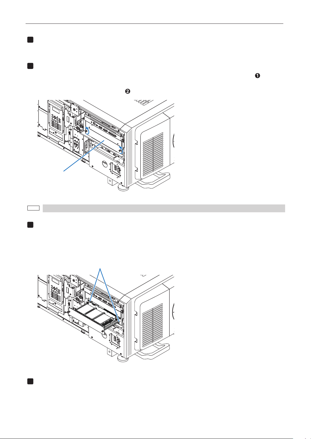
Setting Up Your Projector
1
2
NOTE
3
4
Remove the side panel.
Side panel of the projector should be removed to mount the option board. For the procedure of removing the side panel,
refer to “1-5-2. Removing and Mounting the Side Panel” (page 53).
Remove the blocking panel from slot.
1. Loosen the knurled screws (2 places) of slot until their rotations become idle ( ). Screws
cannot be removed.
2. Remove the blocking panel ( ).
Slot
Carefully store the blocking panel and screws that you removed.
Mount the option board to the projector.
1. Insert the board by following the guide on either side of the slot.
2. While pushing up and holding the board, tighten up the knurled screws (2 places) until
it fix.
guide (left/right)
Mount the side panel to the projector.
This completes the mounting of option board. Next, clear any tamper events. For details on how to clear tamper events, refer to
“3-2. Recovering from Tamper Errors” (page 103). A setting to use option board is needed, after recovering from tamper error. For
the procedure, refer to “2-8-1. Make the option board usable” (page 100).
99
Page 100

Setting Up Your Projector
1
2
3
4
5
6
2-8-1. Make the option board usable
By registering the mounted option board to the slot, you can use option board by setting up the projector. This procedure is
described for the example, when IMB (NP-90MS02) is mounted to slot. For the operation of the projector, refer to projector’s “User’s
Manual”.
TIP
DCC can be used to set up.
For the procedure by using DCC, refer to “Digital Cinema Communicator v2 Installation Manual”.
Set the projector in standby mode.
Enable the service personnel menu.
These settings are for our service personnel and cannot normally (user mode) be used. You need to enter a passcode to
enable the service personnel menu. Refer to the “4-1-1. When You Use the Service Personnel Menu” (page 121) for the
procedure.
Press the MENU button on the control panel.
“Title Select” is displayed in the menu. From this procedure on, control panel of the projector will be used.
Press the LEFT/RIGHT button to display “Configuration” and press the DOWN button.
Press the LEFT/RIGHT button to display “Installation” and press the DOWN button.
Press the LEFT/RIGHT button to display “Option Slot” and press the DOWN button.
100
 Loading...