

NEC NLT-40PAN Service Manual
SERVICE MANUAL
NLT-40PAN
40inch TFT-LCD TV/MONITOR
2007. 09. 15

1
CONTENTS
1. SAFETY PRECAUTION
‥‥‥‥‥‥‥‥‥‥‥‥‥‥‥‥‥‥‥‥‥‥‥‥
2
2. BLOCK DIAGRAM
‥‥‥‥‥‥‥‥‥‥‥‥‥‥‥‥‥‥‥‥‥‥‥‥‥‥
3
3. GENERAL SPECIFICATION
‥‥‥‥‥‥‥‥‥‥‥‥‥‥‥‥‥‥‥‥‥
13
4. TROUBLE SHOOTING
‥‥‥‥‥‥‥‥‥‥‥‥‥‥‥‥‥‥‥‥‥‥‥‥
16
5. CONTROLS OF FRONT PANEL
‥‥‥‥‥‥‥‥‥‥‥‥‥‥‥‥‥‥‥‥
19
6. CONNECTIONS OF BACK PANEL
‥‥‥‥‥‥‥‥‥‥‥‥‥‥‥‥‥‥
20
7. REMOTE CONTROL HANDSET
‥‥‥‥‥‥‥‥‥‥‥‥‥‥‥‥‥‥‥
21
8. PCB LAYOUT
‥‥‥‥‥‥‥‥‥‥‥‥‥‥‥‥‥‥‥‥‥‥‥‥‥‥‥‥
23
9. SCHEMATIC DIAGRAM
‥‥‥‥‥‥‥‥‥‥‥‥‥‥‥‥‥‥‥‥‥‥
25
10. EXPLODED VIEW
‥‥‥‥‥‥‥‥‥‥‥‥‥‥‥‥‥‥‥‥‥‥‥‥‥
37
11. REPLACEMENT PARTS LIST
‥‥‥‥‥‥‥‥‥‥‥‥‥‥‥‥‥‥‥‥
38
2
1. Safety Instructions
Important Safety Notice
Many electrical and mechanical parts in this chassis have special safety-related characteristics.
These parts are identified by in the Schematic Diagram and Replacement Parts List.
It is essential that these special safety parts should be replaced with the same components as
recommended in this manual to prevent Shock, Fire, or other Hazards.
Do not modify the original design without permission of manufacturer.
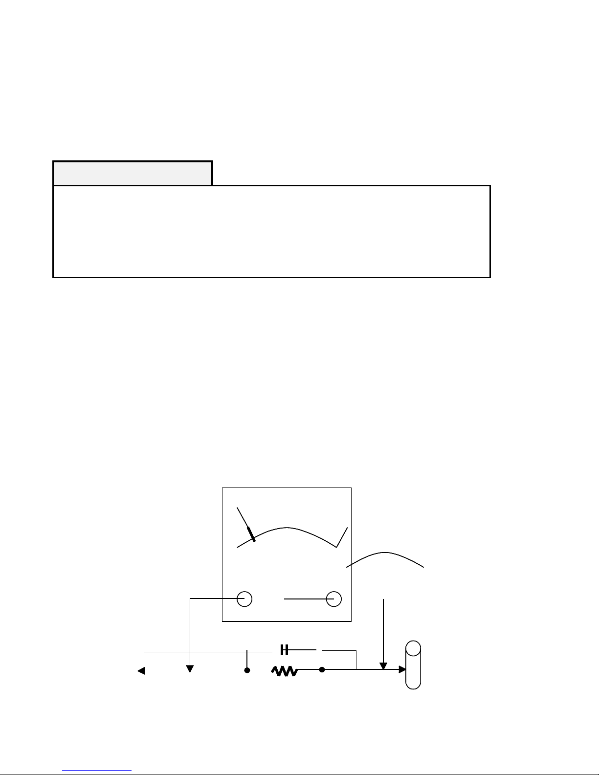
Leakage Current Hot Check (See below Figure)
Plug the AC cord directly into the AC outlet. Do not use a line Isolation Transformer during this check. Connect
1.5K/10watt resistor in parallel with a 0.15uF capacitor between a known good earth ground (Water Pipe, Conduit, etc)
and the exposed metallic parts. Measure the AC voltage across the resistor using AC voltmeter with 1000 ohms/volt or
more sensitivity. Reverse plug of the AC cord into the AC outlet and repeat AC voltage measurements for each exposed
metallic part. Any voltage measured must not exceed 0.75 volt RMS, which is, corresponds to 0.5mA. In case any
measurement is out of the limits specified, there is possibility of shock hazard and the set must be checked and repaired
before it is returned to the customer.
AC Volt-meter
Good Earth Ground
such as WATER PIPE,
CONDUIT etc.
1.5 Kohm/10W
0.15uF
To Instrument’s
exposed
METALLIC PARTS
AC Volt-meter
Good Earth Ground
such as WATER PIPE,
CONDUIT etc.
1.5 Kohm/10W
0.15uF
To Instrument’s
exposed
METALLIC PARTS
3
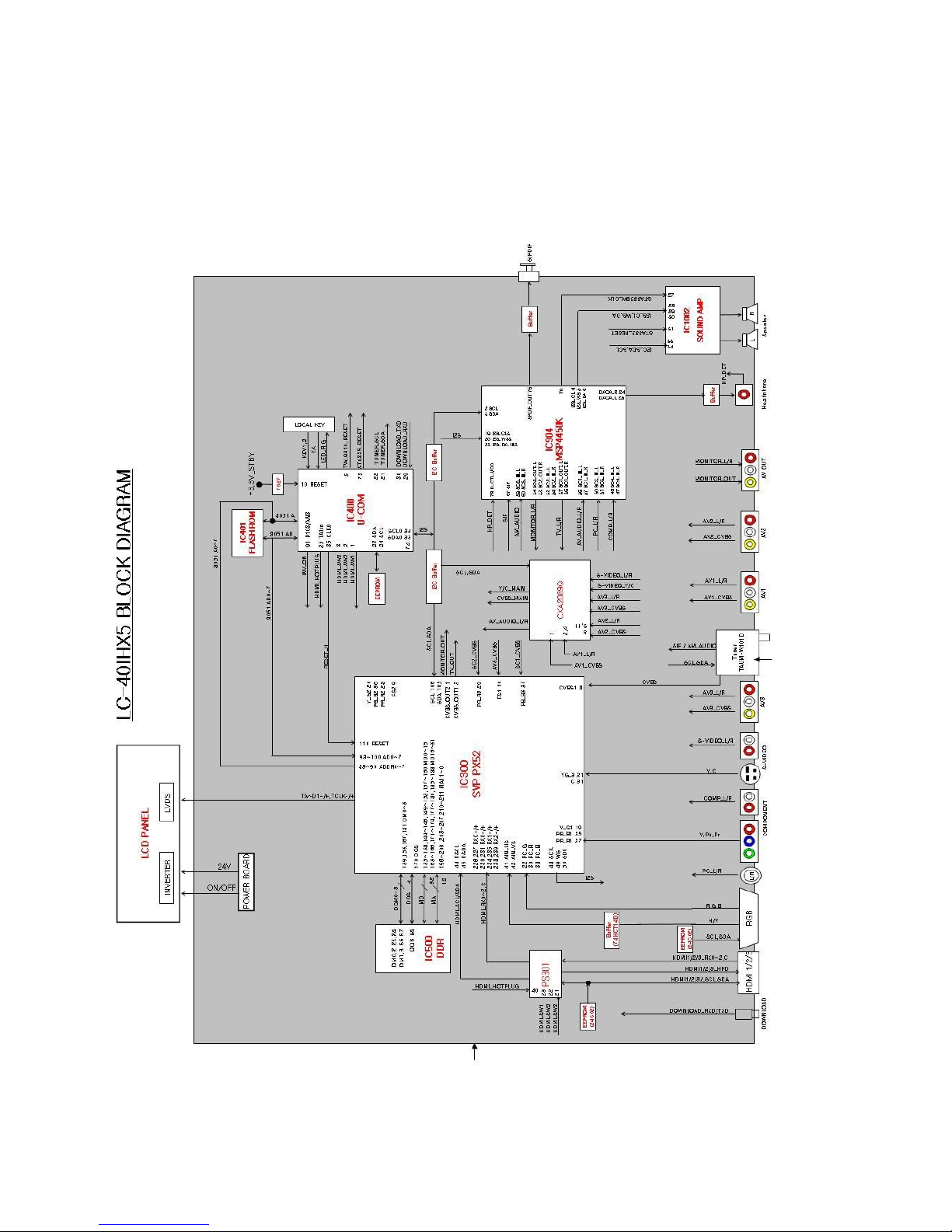
2. BLOCK DIAGRAM
■ BLOCK DIAGRAM
4
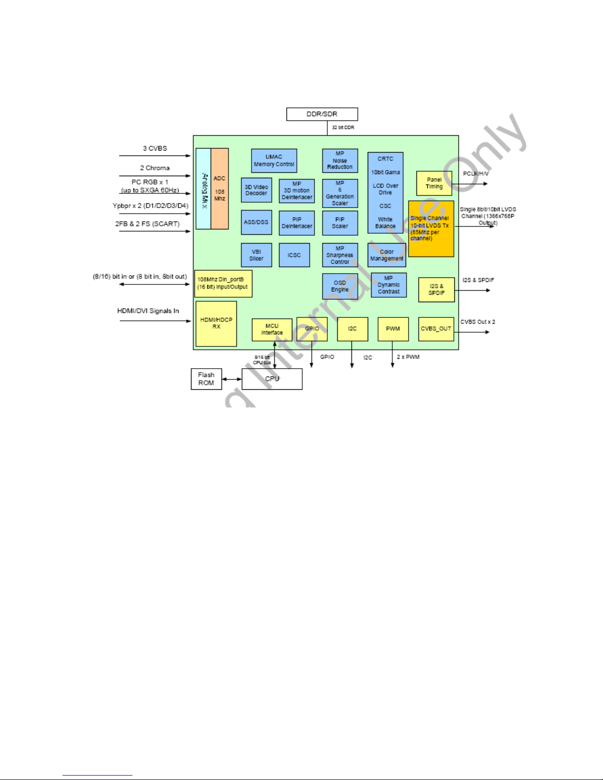
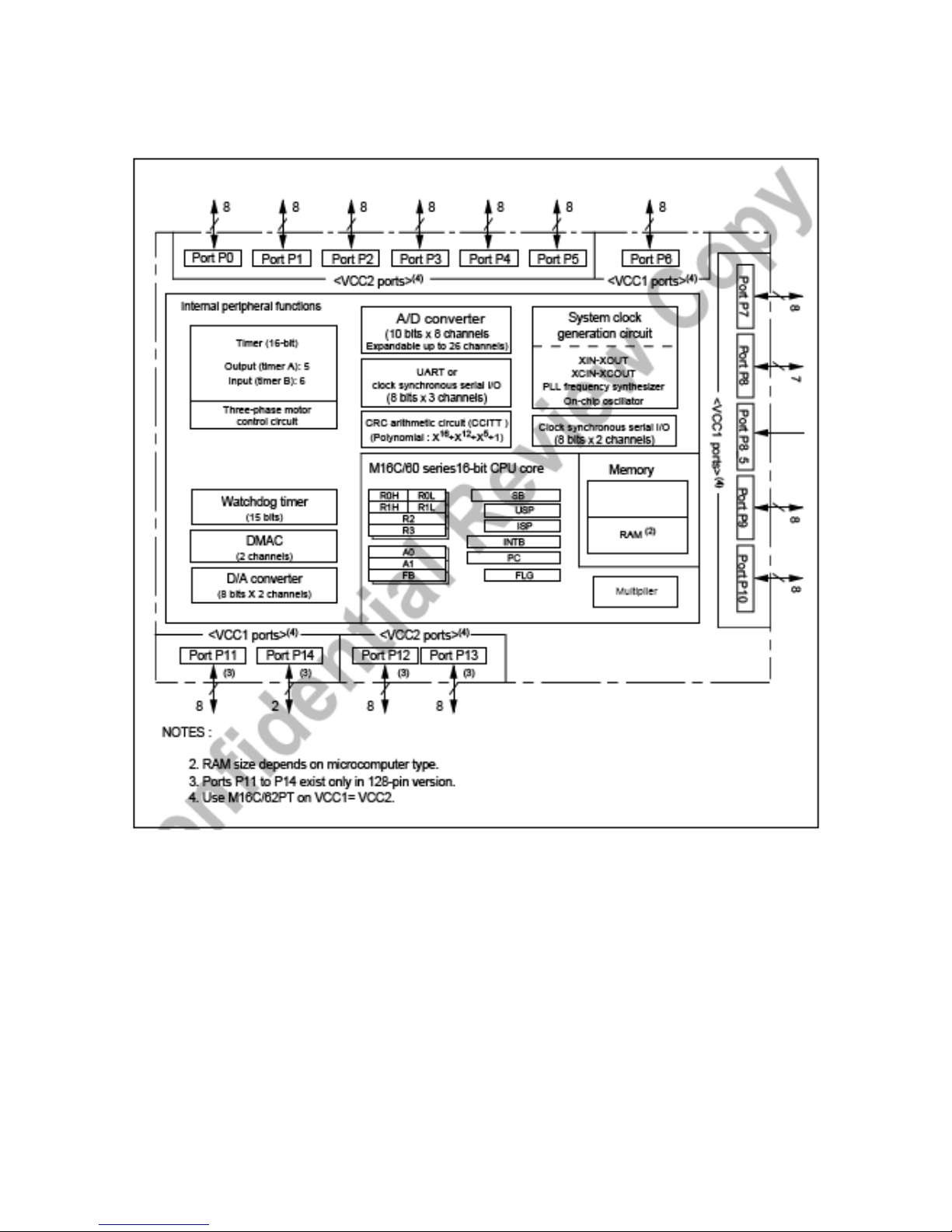
■
IC FUNCTIONAL BLOCK DIAGRAM (SVP-PX52)
5
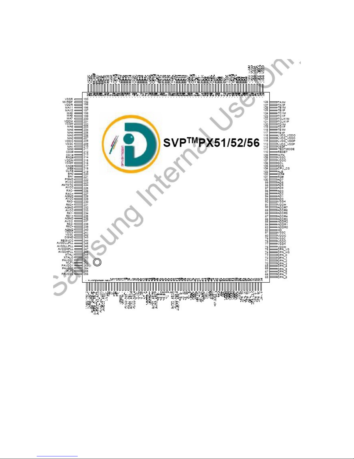
■
IC PIN ASSIGNMENT (SVP-PX52)
6
■ IC BLOCK DIAGRAM (M30300SAGP#U5C)
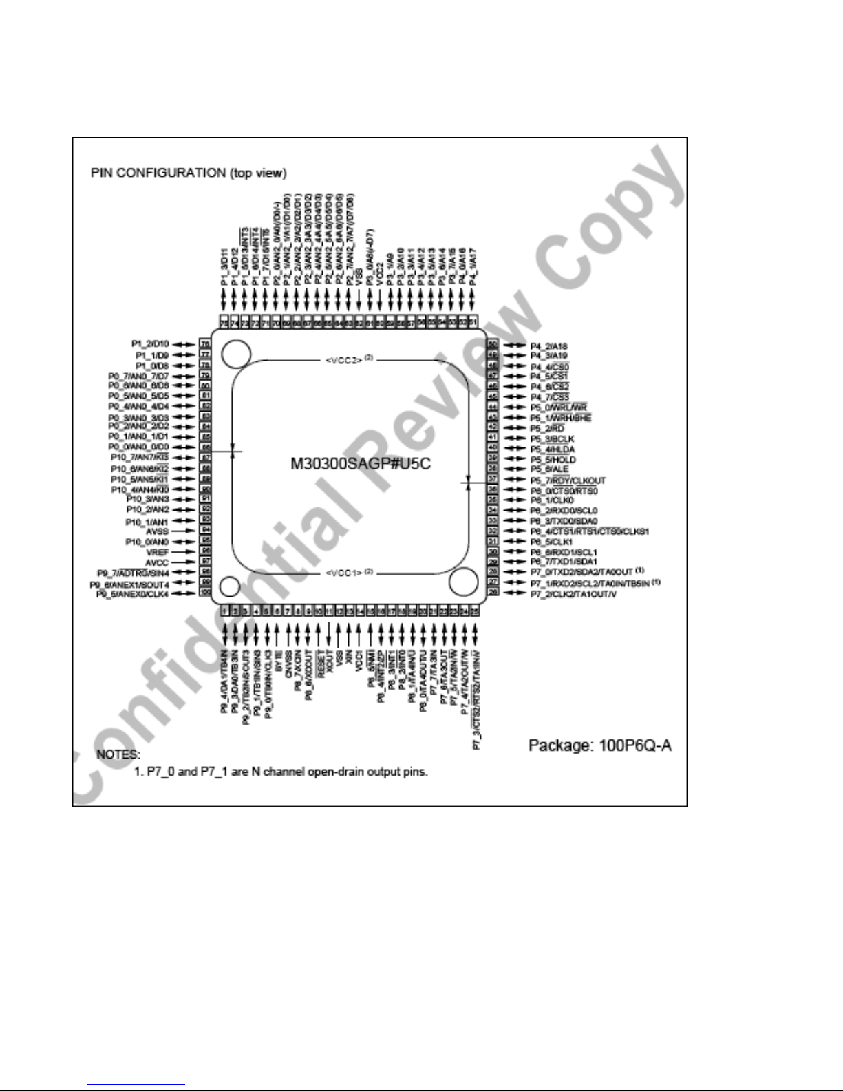
7
■ IC PIN OUT (M30300SAGP#U5C)
8
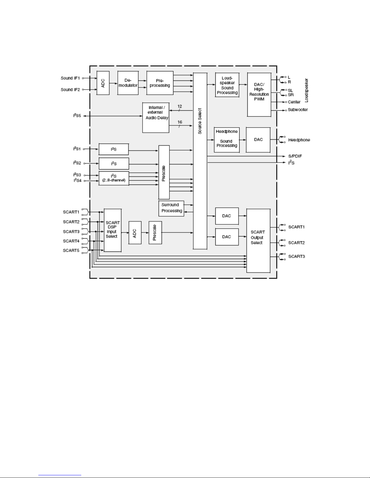
■ IC BLOCK DIAGRAM (MSP44/46xyK,PMQFP80-1)
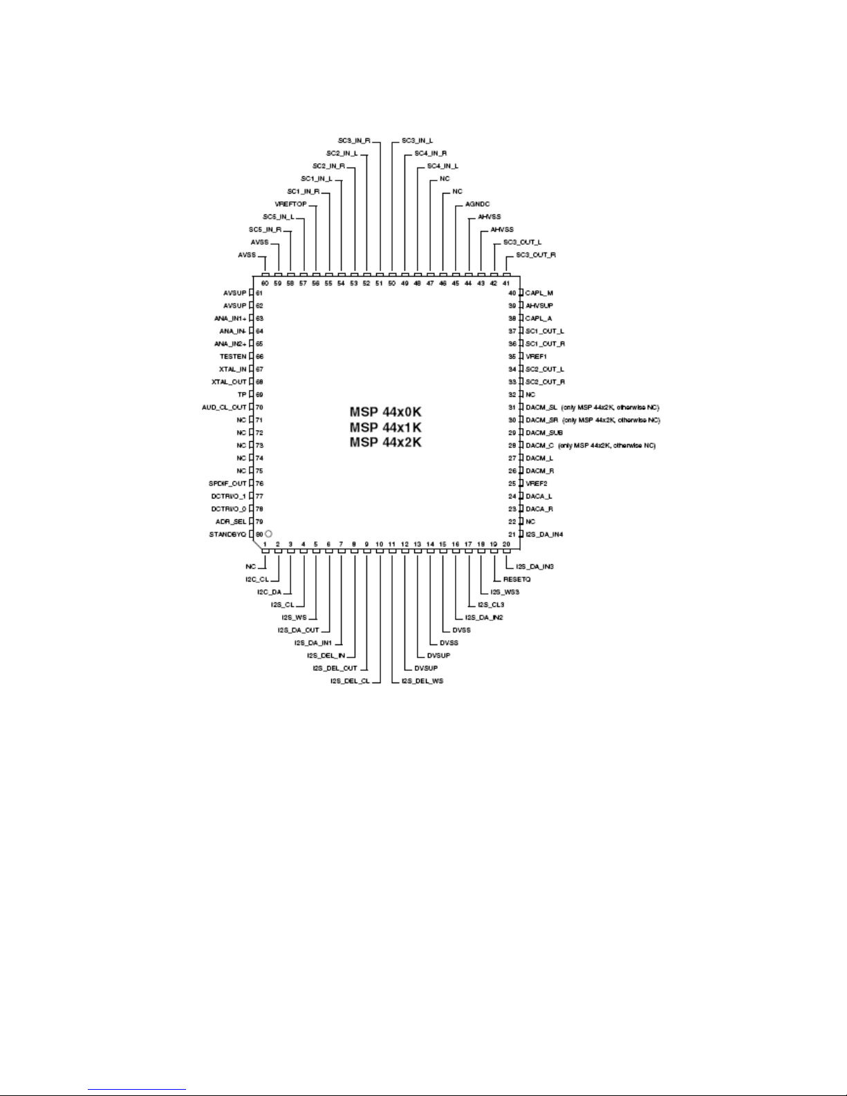
9
■ IC PIN OUT (MSP44/46xyK,PMQFP80-1)
10
■
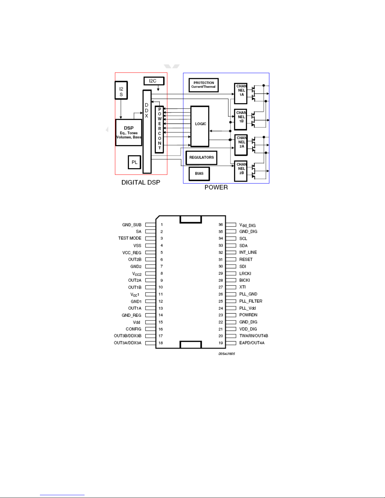
IC BLOCK DIAGRAM (STA335BW)
■
IC PIN OUT (STA335BW)
11
■
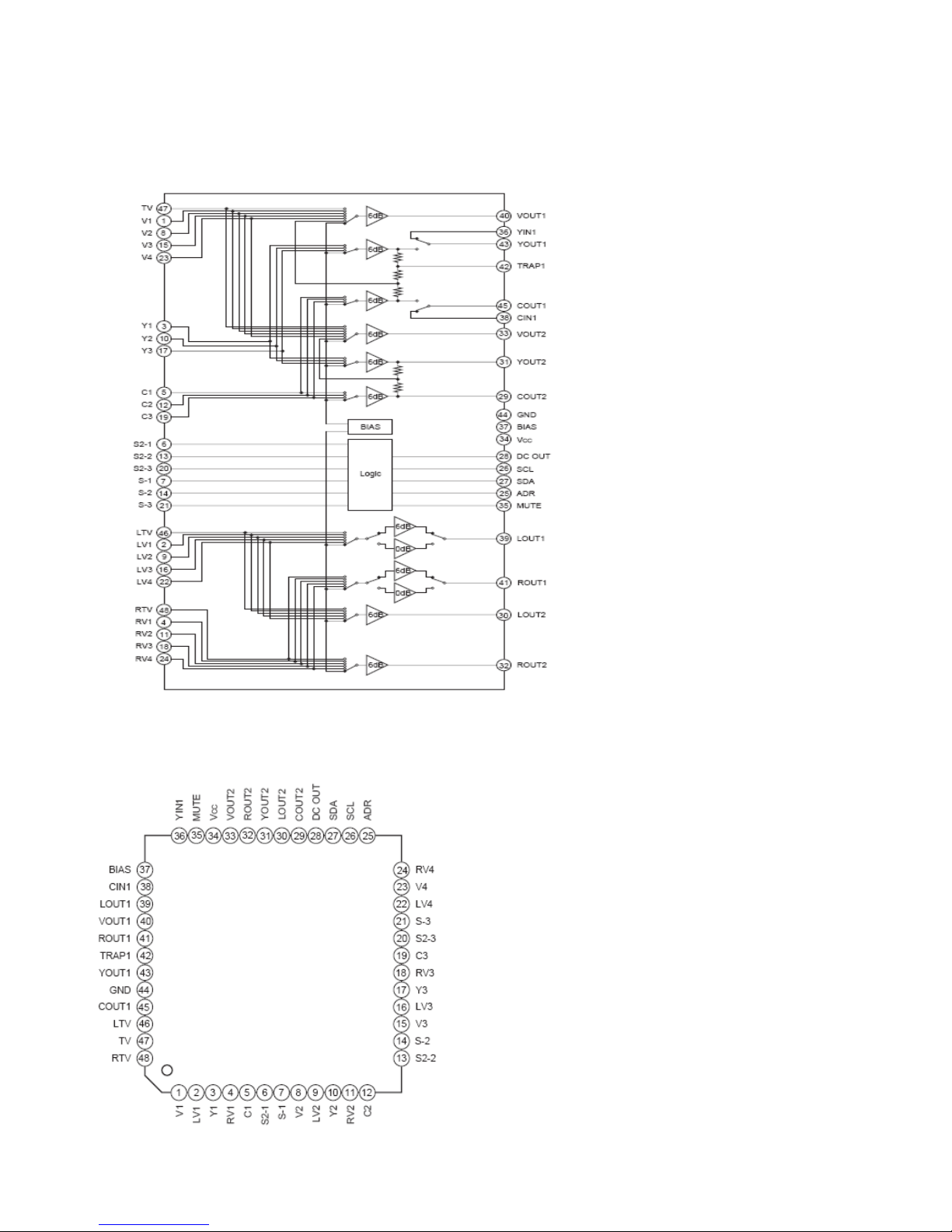
IC BLOCK DIAGRAM (CXA2089Q,QFP)
■
IC PIN OUT (CXA2089Q,QFP)
12
■
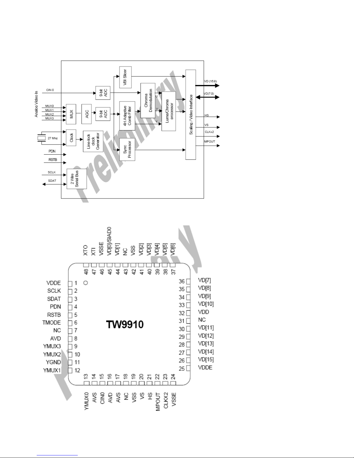
IC BLOCK DIAGRAM (TW9910,QFN)
■
IC PIN OUT (CXA2089Q,QFP)
13
3. General Speci;cation
No Item Specification Remark
Min Typ Max Unit
1. Video Input 1) NTSC M
2) NTSC 4.43
3) PAL
4) SECAM
3.579545 / 60 Hz
4.433618 / 60 Hz
4.433618 / 50 Hz
4.286 / 50 Hz
2. Component Input 480i/59.94/60Hz
576i/50Hz
480p/59.94/60Hz
576p/50Hz
720p/50/59.94/60Hz
1080i/50/59.94/60Hz
Table 1.
(Component)
3. RGB DTV Input 480i/59.94/60Hz
576i/50Hz
480p/59.94/60Hz
576p/50Hz
720p/50/59.94/60Hz
1080i/50/59.94/60Hz
Table 2.
(RGB DTV)
4. RGB PC Input VGA (640x480)
SVGA (800x600)
XGA (1024x768)
SXGA (1280x1024)
MAC
Table 3.
(RGB PC)
5. HDMI(DVI) DTV Input 480i/59.94/60Hz
576i/50Hz
480p/59.94/60Hz
576p/50Hz
720p/50/59.94/60Hz
1080i/50/59.94/60Hz
Table 4.
(DVI DTV)
6. HDMI(DVI) PC Input VGA (640x480)
SVGA (800x600)
XGA (1024x768)
SXGA (1280x1024)
MAC
Table 3.
(DVI PC)
8. Input Voltage AC 100 ~ 240 V, 50hz / 60hz
9. External Interface RGB PC/RGB DTV
Input
1 D-Sub 15 Pin
PC Sound Input 1 Ear-phone Jack
(RGB PC,HDMI
공용
)
HDMI(DVI) Input 3 HDMI Connector
COMPONENT Input 1 RCA 3P
Component L/R 1 RCA 2P
AV Input 3 RCA 3P
AV Out 1 RCA 3P(Side)
S-VIDEO Input 1 S-VIDEO JACK
S-VIDEO Audio Input 1 RCA 2P
SPDIF Input 1 OPTICAL JACK
Headphone out 1 Ear-phone Jack (Side)
10. HDMI(DVI) PC Input VGA (640x480)
SVGA (800x600)
XGA (1024x768)
SXGA (1280x1024)
MAC
Table 3.
(DVI PC)
 Loading...