

NEC S2900, NF2900-SR40E User Manual
NEC Storage S2900
NF2900-SR40E
Disk Array Unit
User's Guide
NOTE:
Read this manual carefully before using the unit. Keep
this manual nearby as a handy reference and refer to
the "CAUTION" and "WARNING" statements whenever
necessary.
All rights reserved by NEC Corporation. This document
must be used solely for the purpose for which it was
furnished by NEC Corporation. No part of this document
may be reproduced or disclosed to others, in any form,
without the prior written permission of NEC Corporation.
856-850822-101-A

Trademarks
Microsoft, Windows, Windows NT, and Windows Server 2003 are registered trademarks or trademarks of
Microsoft Corporation in the United States and other countries.
HP-UX is a registered trademark of Hewlett-Packard Company of the United States.
Solaris is a trademark or registered trademarks of Sun Microsystems, Inc. in the United States and other
countries.
All other product, brand, or trade names used in this publication are the trademarks or registered trademarks of
their respective trademark owners.
Remarks
(1) No part of this manual may be photocopied in any form without prior written consent from NEC.
(2) The information in this manual is subject to change without notice.
(3) All possible efforts are being made to ensure the accuracy of this manual, but in the event that
any technical or editorial errors or omissions are found, contact your dealer.
(4) Save this manual in a convenient area after you finished reading it.
(5) When transferring this unit to another person, be sure to transfer this manual also.
(6) NEC shall not be liable for any loss or lost profits from the use of this disk array unit regardless of
the item in (3).
© NEC Corporation 2006
FEDERAL COMMUNICATIONS COMMISSION
RADIO FREQUENCY INTERFERENCE STATEMENT
NOTE: This equipment has been tested and found to comply with the limits for a Class A digital
device, pursuant to Part 15 of the FCC Rules. These limits are designed to provide reasonable
protection against harmful interference when the equipment is operated in a commercial environment.
This equipment generates, uses, and can radiate radio frequency energy and, if not installed and used
in accordance with the instruction manual, may cause harmful interference to radio communications.
Operation of this equipment in a residential area is likely to cause harmful interference in which case
the user will be required to correct the interference at their own expense.
Momentary voltage drop prevention:
This network storage unit may be affected by a momentary voltage drop caused by lightning. To
prevent a momentary voltage drop, an AC uninterruptible power supply (UPS) unit should be used.
“ Perchlorate Material - special handling may apply.
See www.dtsc.ca.gov/hazardouswaste/perchlorate.”
Safety Precautions
Before using this unit, read this manual carefully and use precaution in order to use this unit safely and
correctly and to avoid any risk of accident or injury to your person or properties. Keep this manual
nearby for easy reference.
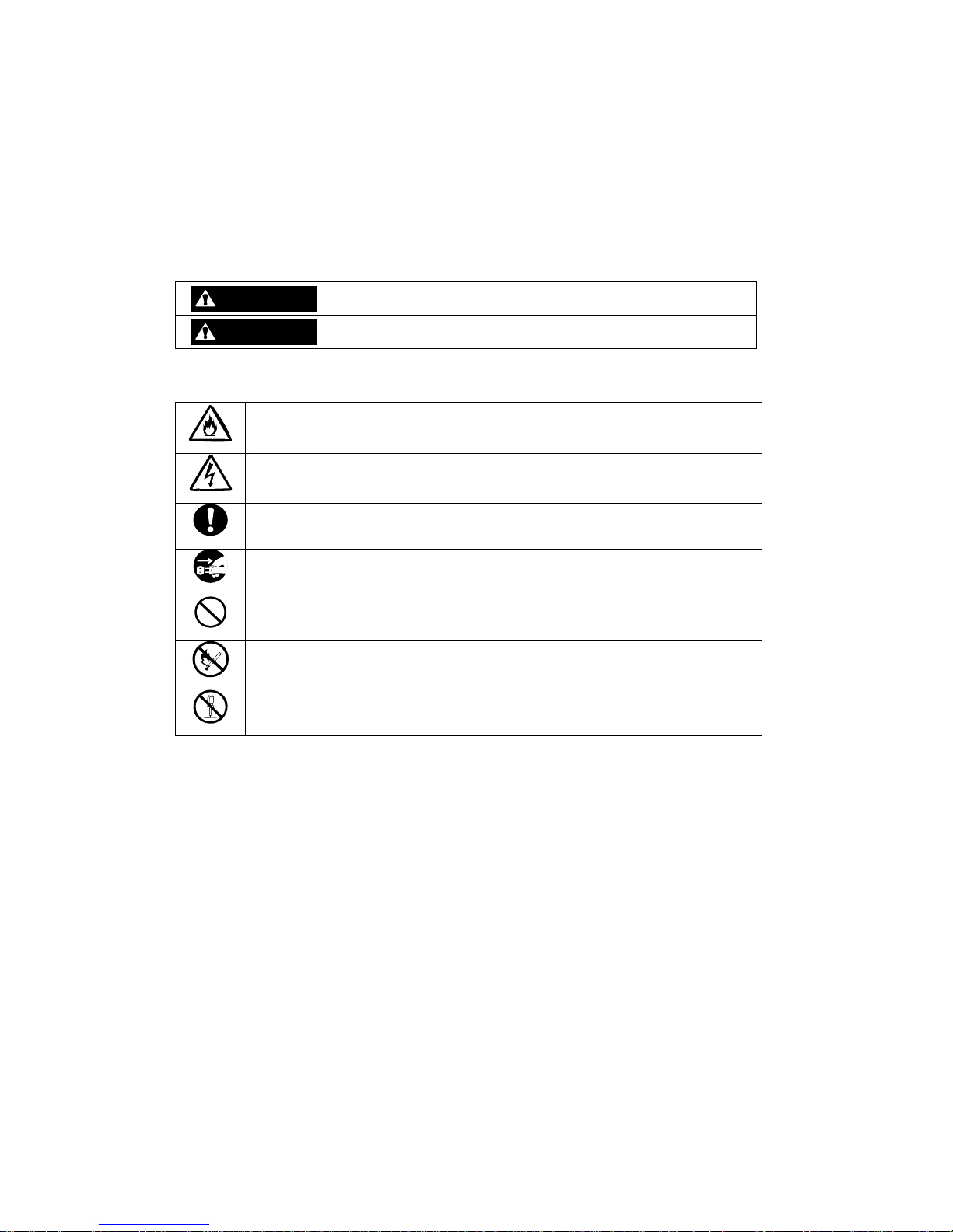
The following symbols are used in this manual so that you can easily understand how to operate the
unit safely and correctly.
WARNING
CAUTION
Indicates there is a risk of death or serious injury.
Indicates there is a risk of burn or injury.
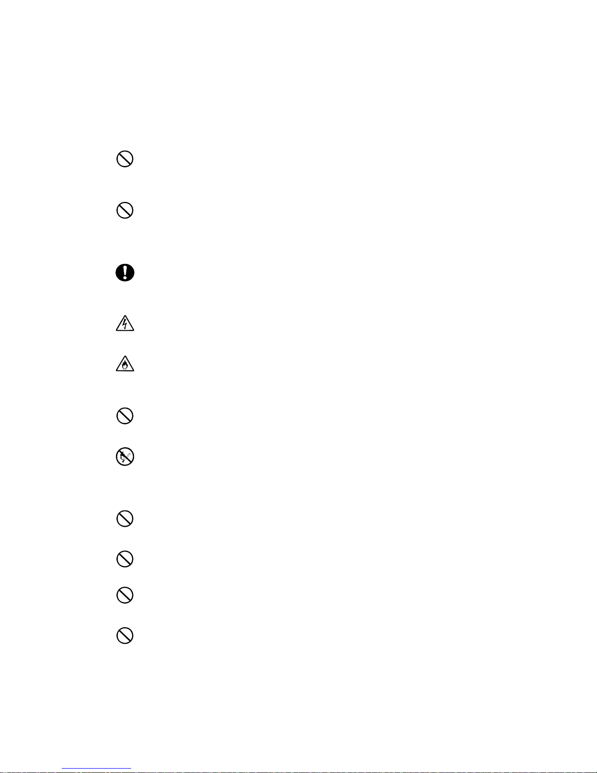
Risks and the necessary actions to reduce risks are indicated indi vidually by the following symbols.
Indicates the risk of smoke emission or fire outbreak.
Indicates the risk of electric shock.
Indicates required general actions for operators.
Indicates instructions to pull out the plug of a power cord from outlet.
Indicates not i c e of general prohib ition.
Indicates instructions to keep a device away from inflammable objects.
Indicates the danger of an injury due to harmful material.
i
Notes on Use
The following includes information necessary for the proper and safe operation of the disk array unit.
WARNING
Do not use the disk array unit in an area with high humidity or water usage. If so,
a fault, electrical shock, or fire may occur.
Do not use the disk array unit in an area where inflammable gas and/or
combustible substance are placed. If so, fire or an explosion may occur.
Do not concentrate power cords to just a few AC outlets. If so, fire may occur.
Do not set heavy materials on any power cord. If so, the coating of the power
cord may be broken, fire may occur, and/or you may be electrically shocked.
Do not insta ll the disk array unit in an a rea of high humidity or dust. Remove any
dust adhering to AC outlets and the plugs of power cords. If dust accumulates on
an AC outlet and/or plug, fire may occur.
Do not connect the plug of a power cord to an AC outlet with wet hands. If so, you
may be electrically shocked.
The disk array unit can accept the power in the range of 100 - 240 VAC (50/60
Hz). Using power of a diff erent voltage may cause electric shock, smoke, and/or
fire to occur.
The controller of the disk array unit contains a lithium battery. Do not remove the
lithium battery. The li thium battery may explode when it is brought close to fire or
when immersed in water. Dispose of the controller according to local ordinances.
Contact your local government for details.
If the disk array unit does not operate normally due to the life of the lithium
batteries, contact your service representative. Do not disassemble the controller,
or replace or c harge the batte ry by yourself.
CAUTION
Do not install the disk array unit and the host systems in an unstable environment.
If so, the equipment may fall causing injury to you and/or the array.
Do not install the disk array unit and the power cords in any area with direct
sunshine or near any apparatus generating heat such as a heater. If so, a fault may
occur. Further, the protective coating of the power cords may be damaged causing
fire or electric shock to occur.
Insert the plug of a power cord to an AC outlet securely. Any power cord shall be
routed with sufficient margin to avoid excess force from being given to the plugs of
the power cord or the power cord itself. If a power cord is removed from the AC
outlet during operation, data may be lost and/or a fault may occur.
To prevent electric shocks, connect the array power cord to an earth grounded AC
outlet. Connection of the grounding line to a gas pipe is extremely dangerous. Never
do it.
ii
Connect or remove a periphe ral device from the disk array unit after turning off all
the power supplies of the disk array unit and peripherals and pulling out the power
cords from the AC outlets. If not, some units may be broken and/or you may be
electrically shocked.
To carry or reinstall the disk array unit, disconnect all cables and power cords
beforehand. If not, some units may be broken, you may be electrically shocked,
and/or a fire may occur.
Handle optical fibers carefully and gently.
The minimum bending radius of optical fiber shall be 30 mm.
Dust and/or dirt may attenuate the optical power of optical fiber causing data errors
to occur. Clean any optical fiber cable whenever it is inserted into the mating
connector with the following procedure.
1. Blow parts cleaning gas (e.g. compressed air) to the connector of the optical fiber
cable for several seconds.
2. Wipe the connector with a non-woven cloth soaked with alcohol for several passes.
3. Apply the compressed air to the connector again.
To install the unit in a rack, observe the following guidelines.
1. TMRA – If installed in a rack, consideration should be given to installing the
equipment in an environment compatible with the TMRA.
2. Reduced Air Flow – Installation in a rack should be such that the amount of air flow
required for safe operation of the equipment is not compromised.
3. Mechanical loading – Mounting of the equipment in the rack should be such that a
hazardous condition is not created due to uneven mechanical loading.
4. Circuit Overloading – Consideration should be given to the connection of the
equipment to the supply circuit and the effect that overloading the circuits might
have on overcurrent protection and supply wiring. Appropriate consideration of
equipment nameplate ratings should be used when addressing this concern.
5. Reliable grounding – Reliable grounding of rack-mounted equipment should be
maintained. Particular attention should be given to supply connections other than
direct conn ections to the branch circuit (e.g., use of power strips).
Notes on Disposal
Disposing of your used NEC product
In the European Union
EU-wide legislation as implemented in each Member State requires that used electrical and
electronic products carrying the mark (left) must be disposed of separately from normal
household waste. The equipment with this mark may include electrical accessories
(e.g. memory cards). When disposing of used NEC products, you should comply with
applicable legislation or such terms which may have been agreed between NEC and
your company regarding used products. The mark on the electrical and electronic
products only applies to the current European Union Member States.
Outside the European Union
If you wish to dispose of used electrical and electronic products outside the European Union,
please contact your local authority and ask for the correct method of disposal.
iii
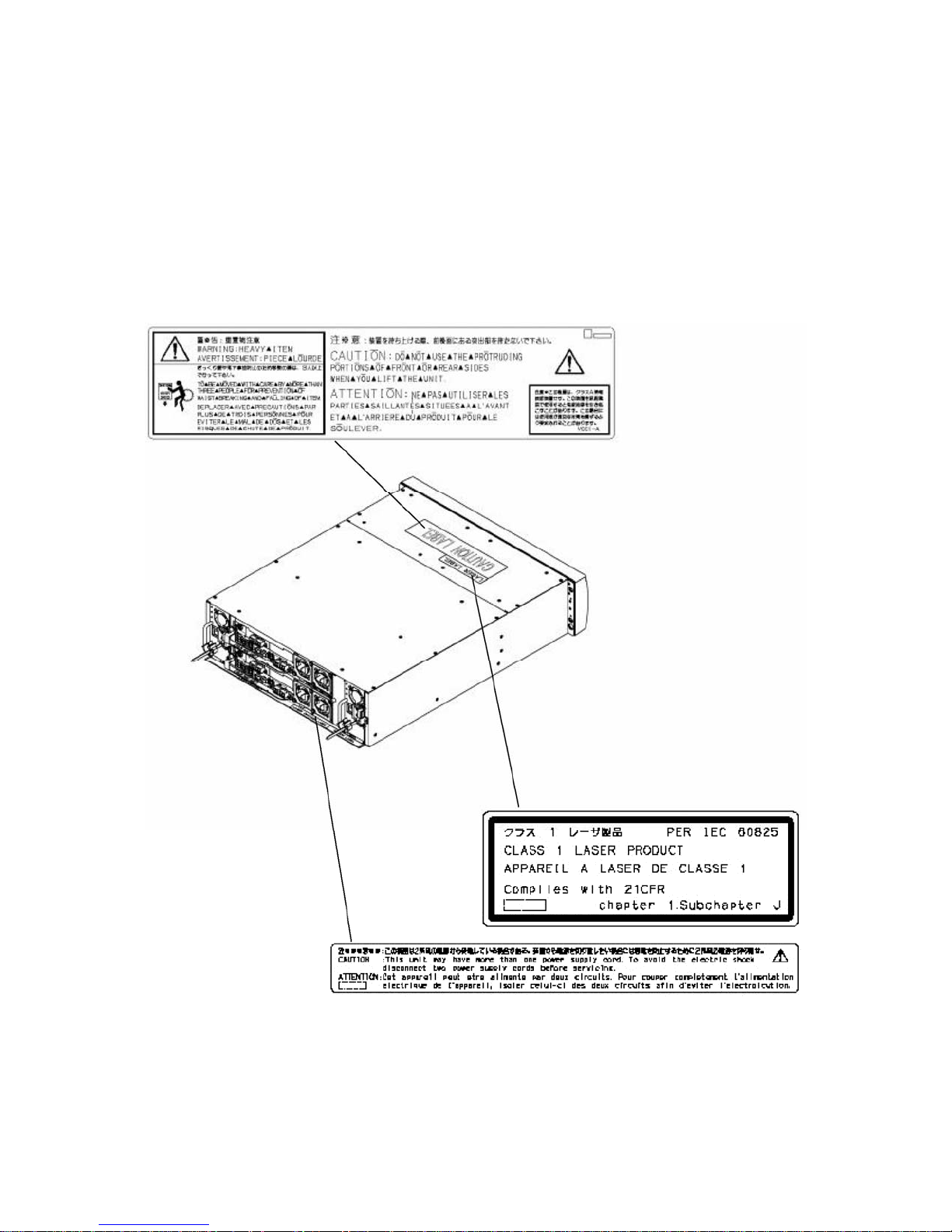
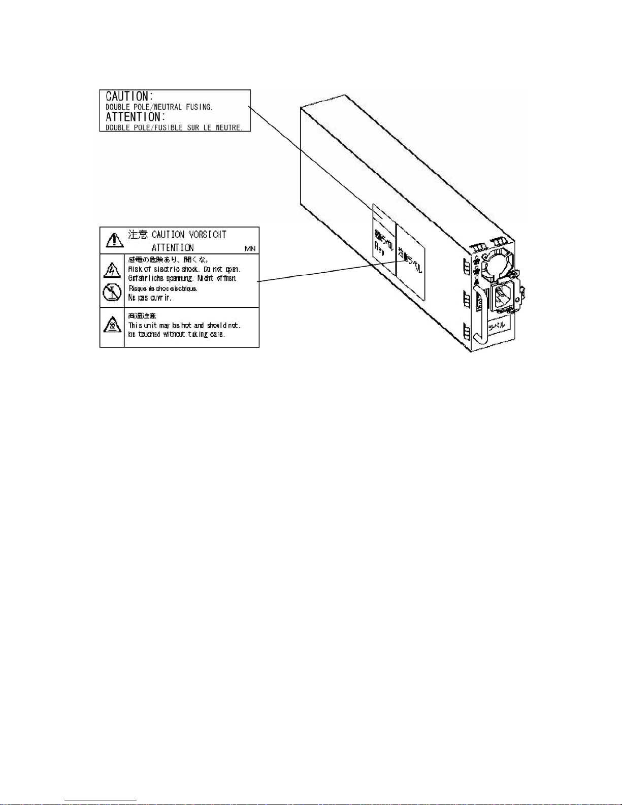
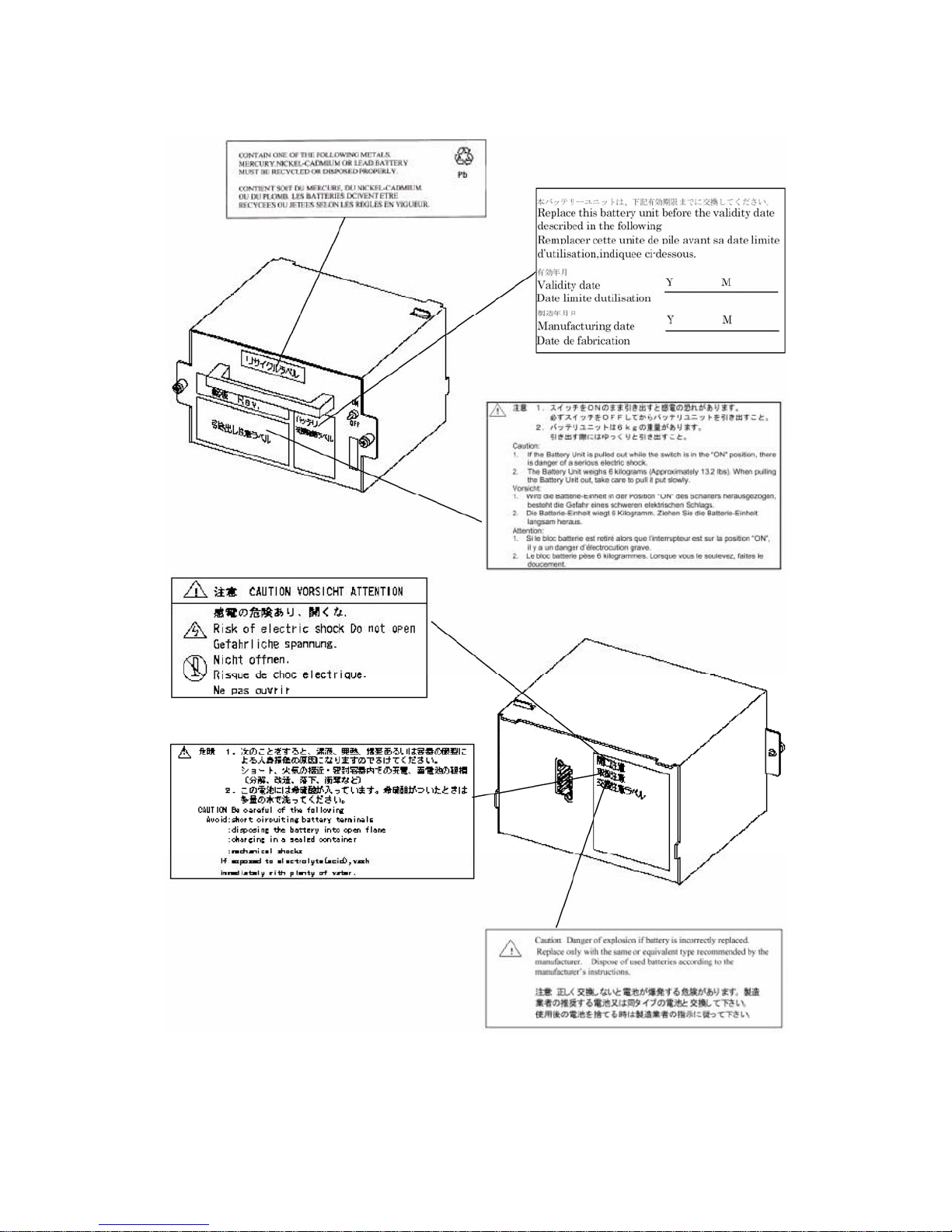
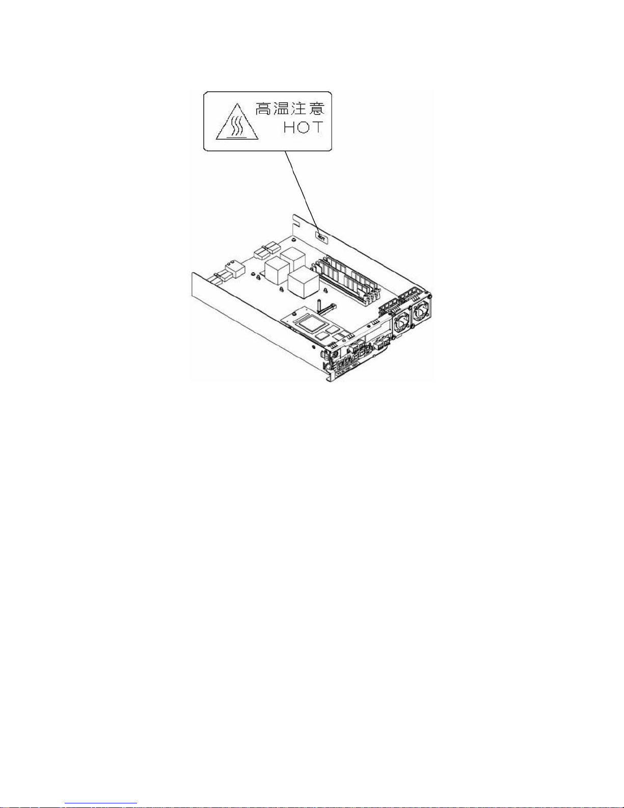
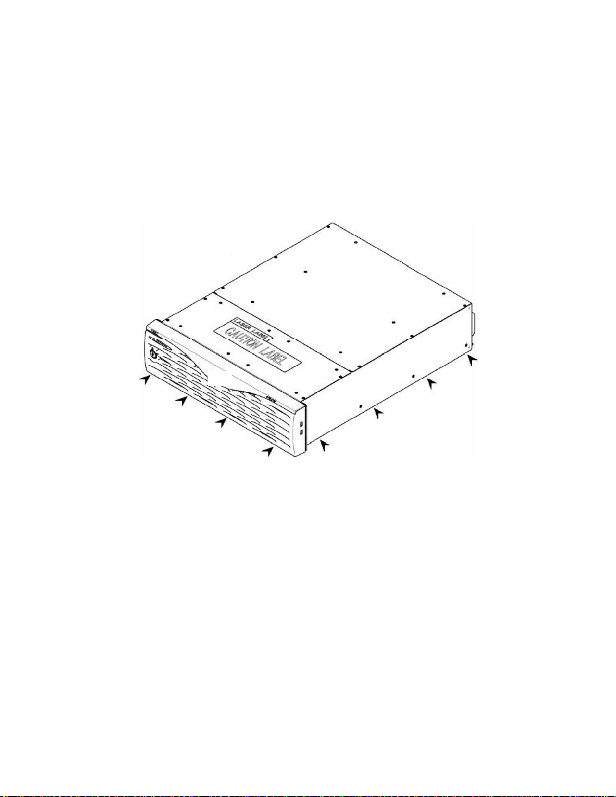
Notes on Safety
The warning label is attached in the vicinity of or directly to components in your disk array unit that
pose a possible danger and to inform the user that a hazardous situation may arise when oper ati ng t he
disk array unit. (Do not intentionally remove or damage any of the labels.)
If you find any labels totally/partially removed or illegible due to damage, contact your sales
representative.
iv
v
vi
vii

Preface
Thank you very mu ch for your purchase of the disk array unit. This manual is intended to enable you
to correctly use the disk array unit NF2900-SR40E connected with the NEC Express5800 series,
NX7000/NX7700 series, or CX5000 series system.
Before using the disk array unit, also read the manuals of several devices including the NEC
Express5800 , NX7000/NX7700 or CX5000 series, your FibreChannel controller, and any FC-AL
SCSI connection mechanism, to be connected with the disk array unit as well as the manual of the
operating system in use.
NEC Storage BaseProduct software needs to be purchased separately before using the disk array unit.
Various options, such as the FC disk drive option which enables extension of equipment capacity, the
cache extension memory option which enables extension of the cache memory capacity, the Disk
Expansion port option which enables extension of the DE ports, and a rack-mounted kit option for
installing in racks other than standard, are available for yourNF2900-SR40 disk-array equipment.
Please read Chapter 9.2 "Optional Parts" for details.
After reading the manual, store it in an area where you can access it easily.
1st edition, September 2006
viii

Check of Components in the Package
(1) Unpacking
Open the package and carefully remove the disk array unit and accessories from the package.. The
disk array unit is very heavy. Accordingly, if two people or less lift the unit, personal injury may
occur. At least three people should remove the disk array unit from the package. Always support the
bottom of the unit and never carry the unit by grasping the power supply on the rear face or the
projections of the controller.
The package is special l y designed for carriage of a precision device. Do not dispose of the package
because it is required to return the disk array unit to the factory for any repairs.
(2) Inspection
After unpacking, check that all the components listed in the table below are provided. If any of the
components is missed, contact your sales representative. Next, inspect the disk array unit and
accessories. If any of the components is damaged, contact your sales representative.
No. Product name Remarks Qty
1 NEC Storage S2900 1
2 Front bezel For NEC Storage S2900, with
security key
3 User's Guide (this document) 1
4 Rack mount kit For NEC Storage rack (L and R) 1
5 Modem Cable (Length 1 m, for connection
between modem and DAC)
6 Express Builder software 1
7 NF2800 Event Logging Tool SD card 1
8 Packing list 1
9 Notes on Use 1
1
1
* Use the FC cable (HSSDC-HSSDC) provided with the disk array unit or the available optionally
DE cable (NF9120-SJ34E) for connecting disk array unit with the FC disk enclosure/SATA. disk
enclosure.
ix

NF2900-SR40E
x
Legend
Symbols in the Text
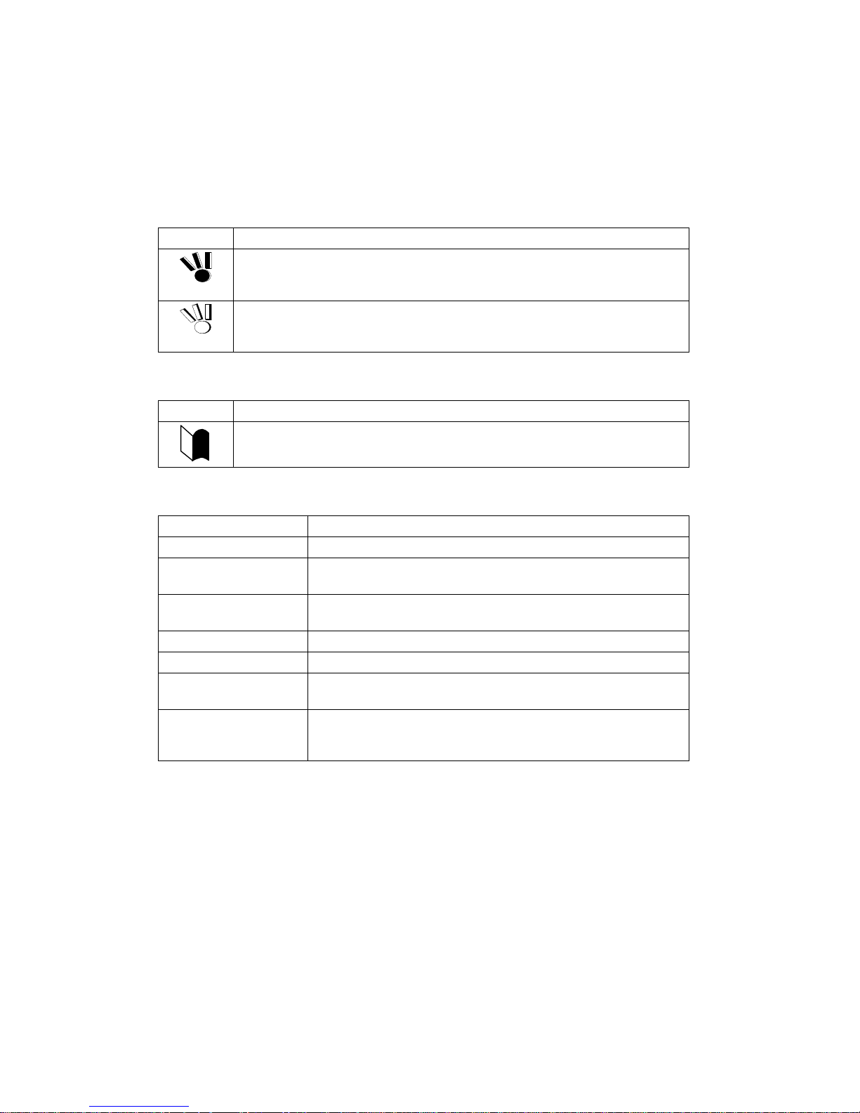
This User's Guide uses the following symbols to indicate improper handling which may cause the disk
array unit to become defective.
Symbol Description
If the description is ignored while handling the disk array unit, the unit may
become defective, software used in the unit may become corrupted, and/or
the data created by the user may be lost.
If the description is ignored while handling the disk array unit, the unit may
become defective and/or software used in the unit may not function
properly.
This User's Guide also uses the following symbol.
Symbol Description
Supplement of the text
This User's Guide uses the following terms to indicate specific devices.
Disk array unit NF2900-SR40E.
Array controller The NEC Storage S2900.
FC Disk enclosure The NEC Storage S2900 FC disk enclosure
(sold separately).
SATA Disk enclosure The NEC Storage S2900 SATA disk enclosure (sold
separately).
Disk drive The hard disk drive with dedicated tray.
Dummy tray The dedicated tray only, with no hard disk drive installed.
Host system The NEC Express5800 series, NX 7000/NX7700 series, or
CX5000 series.
Host bus adapter The FibreChannel controller for NEC Express5800 or CX5000
series or the FC-AL SCSI connection mechanism for the NEC
NX7000/NX7700 series,
xi

Contents
1. Notes on Installation and Handling of Disk Array Unit..........................................1
1.1 Note on Carrying theDisk Array Unit ...............................................................................1
1.2 The Disk Array Unit Installation Environment................................................................. 2
1.3 Installation and Connection of the Disk Array Unit.......................................................... 3
1.4 Notes on Use of the Disk Array Unit....................................... ... .... ... .... .... ... .... .... ... .... ... ... 4
1.5 Routine Inspection of the Disk Array Unit........................................................................ 5
1.6 Notes on Storage and Carriage of the Disk Array Unit..................................................... 6
2. Features of the Disk Array Unit................................................................................ 8
2.1 Hot Spare Feature.............................................................................................................. 9
2.2 Write Cache Feature........................................................................................................ 10
2.3 Management Software.......... .... .... ... .... ... .... .... ... .... ... .... ... .... .... ... .... .... ... .......................... 11
2.4 RAID Configuration................................... ... .... .... ... .... ... .... .... ... .... ... .... .... ... .... ... .... .... ... . 12
3. Names and Roles of Components.........................................................................13
3.1 Array Controller (Front)............... ... .... ........................................... ... .... .... ... .... ... .... .... ... . 13
3.2 Array Controller (Rear)............................................................................. ...................... 15
3.3 Battery Backup Unit........................................................................................................ 16
3.4 Power Supply for Array Controller................................................................................. 17
3.5 Controller ........................................................................................................................ 19
3.6 DE Port (Option) (NF2900-SP02E) ........................................... .... .... ... .... ... .... ... .... .... ... . 22
4. Installation and Connection Procedures...............................................................23
4.1 Installation and Connection Procedures.......................................................................... 23
5. Connection of the Disk Array Unit......................................................................... 25
5.1 Notes on Connection of the Disk Array Unit ............................. .... ... .... .... ... .... ............... 27
5.2 Connection of the Disk Array Unit.................................................................................. 28
5.3 Connection of the Disk Array Unit as Additional Unit ................................................... 36
5.4 Connection of the Ethernet Cable.................................................................................... 40
5.5 Connection of the Power Cords....................................................................................... 41
6. The Addition of Optional Devices..........................................................................44
6.1 Addition of a Disk Enclosure .......................................................................................... 44
6.2 Addition of a DE Port...................................................................................................... 51
6.3 Addition of Cache Memory............................................................................................. 57
7. Handling of the Disk Array Unit .............................................................................64
7.1 Notes on Handling of the Disk Array Unit...................................................................... 64
7.2 Power On/Off of the Disk Array Unit .............................. ... .... ... .... ... .... .... ... .... .... ... .... ... . 65
7.3 LD (Logical Disk) Setting Procedure.................................. .... ... .... .... ... .... ... .... ... .... .... ... . 70
7.4 Spare Disk Setting Procedure... .... ... .... ... .... .... ... .... ... .... ... .... .... ... .... ... .... .... ... .... .... ... .... .... 70
8. Troubleshooting......................................................................................................71
8.1 Troubleshooting Tips ...................................................................................................... 72
8.2 Computer Virus Protection.............................................................................................. 73
8.3 Indications at Occurrence of Fault .................................................................................. 74
8.4 Replacement of a Controller....................... .... ... .... ... .... .... ... .... ... .... ... .... .... ... .... .... ... .... ... . 75
8.5 Replacement of a Controller Cooling Fan...... ... .... ... .... .... ... .... ... .... .... ... .... ... .... .... ... .... ... . 78
8.6 Replacement of a Power Supply for an Array Controller ..................... .... ... .... .... ... .... ... . 79
xii

Replacement of a Battery Backup Unit.. .... .... ... .... ... .... .... ... .... ... .... ... .... .... ... .... ... .... ........ 82
8.7
8.8 Replacement of a Disk Drive ......................... ... .... ... .... ... .... .... ... .... ... .... .... ... .... .... ........... 84
8.9 Replacement of a Power Supply for a Disk Enclosure.................................................... 87
8.10 Replacement of an Adapter........................................................ .... .... ... .... ... .... ... .... .... ... . 92
8.11 Location of Model Name and Serial Numbers............. .... ....................................... .... ... . 95
8.12 Preparations before Contacting Technical Supportl........................................................ 96
8.13 Service and Support................................ .... .... ... .... ........................................... ... .... .... ... . 96
8.14 Unit Life/Repair Service Period...................................................................................... 96
8.15 Disposal of the Disk Array Unit...................................................................................... 96
9. Product Specifications ........................................................................................... 97
9.1 Basic Specifications of the Disk Array Unit.................................................................... 97
9.2 Optional Components...................................................................................................... 98
9.3 Environmental Conditions . ... .... .... ... .... ... .... .... ........................................... ... .... ... .... .... ... . 99
9.4 Power Specification......................................................................................................... 99
9.5 External Dimensions and Weight.................................................................................... 99
9.6 Life Expectancies of Components................................................................................... 99
Appendix A Features of the Disk Array Unit.......................................................... 100
1. Battery Backup......................................................................................................100
2. Repair Time............................................................................................................100
3. Logical Disk Capacity ...........................................................................................100
3.1 Arbitrary Logical Disk Capacity ............................................. ... ................................... 100
3.2 Maximum Logical Disk Capacity ................................................................................. 100
4. Access Control......................................................................................................101
4.1 Port Mode...................................................................................................................... 101
4.2 WWN Mode ................................................... ... .... ... .... ... .... .... ... .... ... .... .... ... .... ............. 101
5. Dynamic Data Replication....................................................................................101
6. Remote Data Replication......................................................................................102
7. Miscellaneous Settings.........................................................................................102
8. Various Default Values.......................................................................................... 102
9. Notes on the Use of DynamicDataReplication/ Remote DataReplication........ 103
10. Setting of Operating System Type....................................................................... 103
11. NEC Storage Software ..........................................................................................104
12. Updating of Control Software...............................................................................104
13. Snap Shot............................................................................................................... 105
13.1 Note on Using Snap Shot ...................................... ... .... .... ... .... ... .... ... .... .... ... .... ... .... .... .. 105
xiii

Appendix B Installation Procedure.........................................................................106
1. Creation of Logical Disks.....................................................................................106
1.1 Binding Logical Disks................................................................................................... 106
Appendix C Use of a Maintenance PC ................................................................... 107
1. Initialization by Maintenance PC.......................................................................... 107
1.1 Connection of Maintenance PC .... ... .... ........................................... .... ... .... ... .... ... .... .... .. 107
1.2 Configuration................................................................................................................. 109
1.2.1 Control Configuration ............................................................................................... 109
1.2.2 Port Configuration..................................................................................................... 110
1.2.3 FC Port Configuration................................................................................................111
1.2.4 Resource Configuration............................................................................................. 115
1.2.5 Network Properties.................................................................................................... 117
2. Confirmation of Unit Setup................................................................................... 119
2.1 Confirmation of FC Port Configuration ........................................................................ 119
2.2 Confirmation of Base Product Setting............... .... ... .... .... ... .... ... .... ... .... .... ... .... .... ... .... .. 120
2.3 Activation on Modification of FC Port Configuration.............................. ... .... ... .... .... .. 121
Appendix D Installing Unit into a Rack ..................................................................122
1. Installing the Rack-mount Kit (Accessory) into an NEC Storage Rack............ 122
1.1 Installing Unit on New Universal Rack Mount Kit....................................................... 122
1.2 Installing Unit on Universal Rack Mount Kit ............................ .... .... ... .... ... .... ... .... .... .. 126
1.2.1 Angle Hole Fitting Rail............................................................................................. 127
1.2.2 Round Hole Fitting Rail ............................................................................................ 133
2. Installing Unit into an HP Rack ............................................................................139
2.1 Installation of Rails ....................................................................................................... 139
2.2 Installation of Unit......................................................................................................... 144
3. Installing Unit into a Sun StorEdge Rack............................................................ 145
3.1 Installation of Rails ....................................................................................................... 145
3.2 Installation of Unit......................................................................................................... 147
4. Installing Unit on an Express Old-type Rack...................................................... 148
4.1 Installing the Rack Mount Kit....................................................................................... 149
4.2 Installation of Unit......................................................................................................... 150
5. Cable Wiring .......................................................................................................... 151
xiv
1. Notes on the Installation and Handling of the
Disk Array Unit
1.1 Note on Carrying Disk Array Unit
Be sure to support the bottom of the disk array unit when carrying it.
Hold the front or side bottom of the disk array unit when possible.
1
1.2 Disk Array Unit Installation Environment
Before installation of the disk array unit, take into account the following items regarding the location,
room temperature, space required fo r ha ndli ng, ventilation, and other environmental conditions.
Install the disk array unit indoors.
Do not expos e the disk ar ray unit to di rect sunlight. Use a window shade or
curtain to block sunlight from the unit if necessary.
Install the disk array unit on a level floor of sufficient strength. In addition, do
not apply shocks and/or vibrations to the disk array unit. If so, some
components may be dropped to cause the disk array unit to be defected and/or
people to be injured.
Install the disk array unit in an area per the following conditions; temperature
range between 5°C - 40°C and humidity range between 10% - 80% (without
condensation).
Do not install the disk array unit in an area of high humidity. If so, a fault or
electrical shock may occur.
Do not install the disk array unit in an environment of chemical steam emission
or an area where the disk array unit may come in contact with inflammable
substances. If so, a fault, fire, or an explosion may occur.
Do not install the disk array unit in a dirty or dusty environment. If so, a fault
may occur.
Do not install the disk array unit and the power cords in any area with direct
sunshine or near any apparatus generating heat such as a heater. If so, a fault
may occur. Further, the protective coating of the power cords may be damaged
causing fire or electric shock to occur.
Do not install the disk array unit near televisions, radios, and cordless
telephones, as interference may occur.
Do not use cellular phones near the disk array unit. If so, a fault may occur.
Do not install the disk array unit near a device generating a strong magnetic
field. If so, a fault may occur.
Install the disk array unit so that the ventilating holes on the front and rear
faces are not blocked. If not, a fault may occur.
2
1.3 Installation and Connection of the Disk Array Unit
WARNING
Do not use the disk array unit in an area of high humidity. If so, a fault,
electrical shock, or fire may occur.
Do not use the disk array unit in an area wh ere inflammable gas and/or
combustible substances are used. If so, fire or anexplosion may occur.
Do not install the disk array unit in a dirty or dusty environment. Remove
any dust adh ering to AC ou tlets and the plugs of power cords. A ny dust
adhering to an AC outlet and/or plug, may be a potential cause of fire.
Avoid overloading AC outle ts with too many devices. If so, fire may occur.
Do not put any heavy materials on a power cord. If so, the coating of the
power cord may be damaged, fire may occur, and/or you may be electrically
shocked.
Always dry your hands prior to connec ting the plug of a power cord to an
AC outlet. If not, you may be electrically shocked.
CAUTION
Make sure to disconnect all power cords and FC cables before relocating
the disk array unit. If not, a malfunction of the system, an electric shock
and/or fire may occur.
The disk array unit can accept power between 100 - 240 VAC (50/60 Hz).
Using power of different voltage may cause electric shock, smoke, and/or
fire to occur.
Do not install the disk array unit and the power cords in an area of direct
sunshine or near any apparatus generating heat such as a heater. If so, a
fault may occur. Further, the insulating coating of the power cord may be
damaged causing fire or electric shock to occur.
The array controller and the disk enclosure weigh 34 kg or more. Hold the
array controller and disk enclosure firmly using at least three people to carry
it. Carrying the devices only by two or less people may cause personal
injury or damage to the unit.
Select the place where the disk array unit can be connected to the AC
outlet by using the attached power cord.
Insert the plug of a power cord into an AC outlet securely. If some
clearance remains between the plug of the power cord and the AC outlet,
dust may enter into the clearance. This then may cause fire to occur.
Provide sufficient margins for the cables connected to the disk array unit so
that the cables do not present an entanglement problem. Prevent power
plugs and FC connectors from suffering excessive force.
3
Do not allow cables connected to the disk array unit to become crimped. If
so, a fault or fire may occur.
Use only NEC approved cables for those connected to the disk array unit
and check the destinations to which the cables are connected. In addition,
always lock power cords and FC cables when they are connected.
Use a power source independent from televisions or radios. Otherwise,
interference may be generated.
To connect a cable to the mating connector, make sure that the connector
of the cable is not damaged and any pins are not bent. Using a cable not
approved by NEC or a damaged cable may cause fire to occur.
To disconnect a cable from the mating connector, always hold the
connector of the cable. Do not pull the cable itself to dis connect it.
1.4 Notes on Use of the Disk Array Unit
Do not let any animal (pets) or children handle the cables connected to the
disk array unit. Pulling the cable may cause the unit to fall down, resulting in
personal injury or failure of the unit.
Do not let any liquids such as water into the disk array unit. If so, you may
be electrically shocked or the unit may become defective. If liquids do enter
into the disk array unit, turn off the power and contact your sales
representative or maintenance engineer. If the disk array unit seems dry,
remember that only a small amount of liquid remaining may cause the unit
to become defective.
Do not let any foreign substances such as clips and screws enter into the
disk array unit through the ventilating holes on the front or rear face. If so, a
fault may occur.
Do not disassemble or modify the disk array unit. If so, a fault or electrical
shock may occur. Also, repair of the unit will be charged regardless of
warranty.
If the disk array unit will not be used for a long period of time, disconnect
the plugs of the power cords from the AC outlets for safety.
Disconnect the power plug from the outlet when a thunderstorm is
approaching. If it starts thundering before you disconnect the power plug, do
not touch any part of the unit including the cables. If any failure is found
later, contact your sales representative.
4
1.5 Routine Inspection of the Disk Array Unit
CAUTION
To clean the disk array unit, always turn off the power and also disconnect
the plugs of the power cords from AC outlets. If not, you may be electrically
shocked.
If a surface of the disk array unit becomes dirty, wipe the surface lightly
with a soft cloth. Wiping the surface using chemicals such as benzene and
thinner, or volatile chemicals, may cause the surface to become deformed
or discolored. In addition, note that spraying insecticide on any surface may
cause the surface to become deformed or discolored.
It is recommended to clean the inside of the disk array unit periodically.
This is because dust may accumulate after the disk array unit has been
used for a long time.
Contact your maintenance engineer for the cleaning of the inside of the disk
array unit.
Users must not disassemble and/or repair the disk array unit because that is
dangerous.
Do not use any Battery Backup Unit exceeding its life. If so, a fault or fire
may occur. (Assumed life of a battery backup unit (BBU): 5 years operating
environment at temperature of 27°C)
5
1.6 Notes on Storage or Carriage of the Disk Array Unit
Do not store the disk array unit in an area where the temperature may
increase extremely or the difference between the warm and cold states is
considerably large. In addition, do not store the disk array unit in an area
with high humidity or dust.
Store the array in the original shipping carton. Note that foreign
substances such as water and metals must not get into the disk array uni t
during storage. Using the disk array unit with any foreign substance inside
may cause a fault, electrical shock, or fire to occur.
During the storage, do not put any materials on the disk array unit. Do not
place the disk array unit anywhere that the unit may fall. To use the disk
array unit after a storage period of longer than six months, it is
recommended to contact your maintenance engineer for inspection and/or
repair.
The array controller and the disk enclosure weigh 34 kg or more. Hold the
array controller and disk enclosure firmly using at least three people to carry
it. Carrying the devices by two or less people may Cause personal injury.Do
not hold the protrusions from the power supply or controller. Doing so
applies excessive force to the power supply and controller. As a result, the
power suppl y or controller may be damaged, and/or the array controller or
disk enclosure may fall and cause personal injury.
Make sure to package the disk array unit with the original packing material
when transporting it. If any other packing materials are used, any vibration
or shock generated during transportation may cause a malfunction of the
unit.
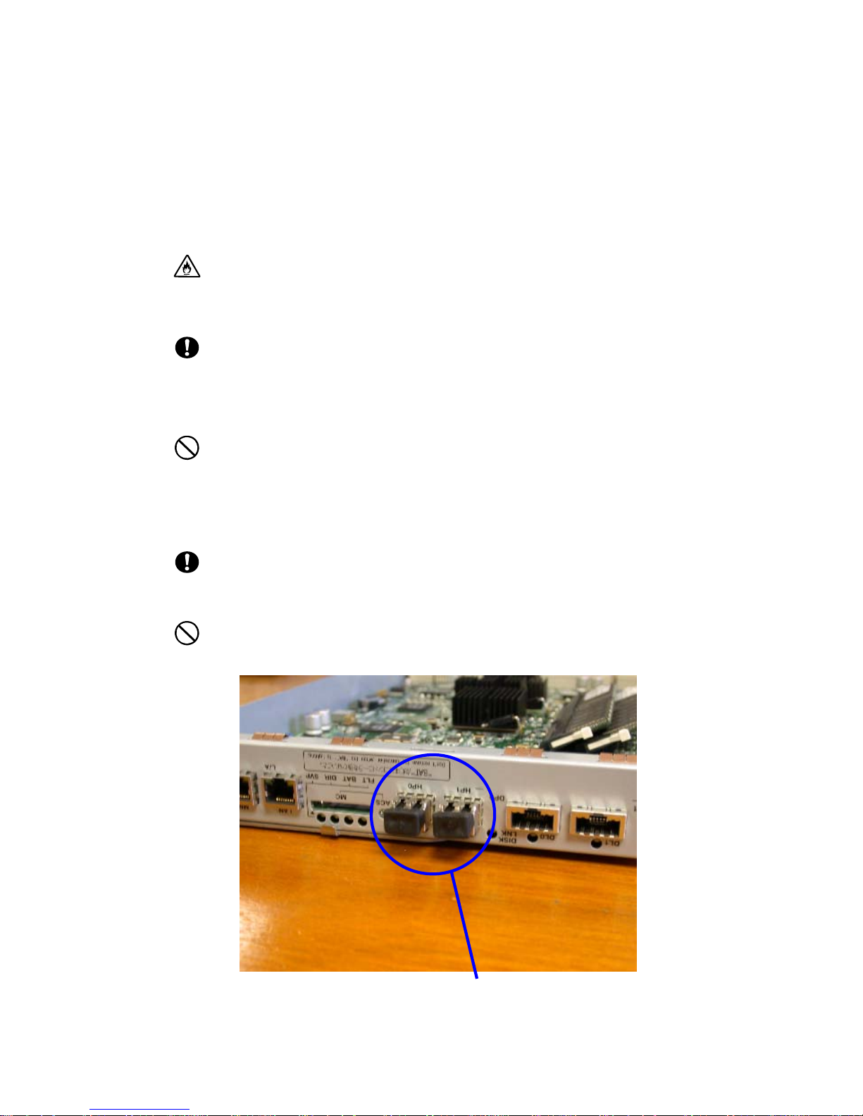
During storage and transporting the disk array unit, attach the dust proof
cover to the FC connectors to prevent dust accumulation. (See the figure
below)
Dust proof cover
6

7
2. Features of the Disk Array Unit
The disk array unit has the following features.
The NF2900-SR40E is a high-performance disk array unit designed for the NEC Express5800,
NX7000/NX7700, and CX5000 systems.
* Ask your sales representative about non-NEC servers (hosts) which are supported and compatible
operating systems.
Fibre Channel (FC) and SATA disk enclosures (optional) to enable the expansion of the storage
capacity of the disk array unit are available.
The NF2900-SR40E supports RAID levels 1, 5, 6, 10 and 50. If a fault occurs in a single disk drive,
theNF2900-SR40E can continue the operation without a loss of data.
Any defective disk drive can be replaced with a new one without system shutdown. Further, the disk
array unit has an auto repair feature which automatically starts data recovery after the replacement of
the defective disk drive.
If a single disk drive is specified as the spare disk, the data in the defected disk drive can be
immediately recovered in the spare disk. The use of this hot spare feature as well as the auto repair
feature allows the data in the defected disk drive to be automatically recovered in the spare disk as
soon as a disk drive becomes defective. This improves the system reliability.
The disk array unit has a cache memory data hold function made a vailable by the cache memory,
power supply, and battery backup unit. The function allows comfortable high-speed data processing to
be done under high reliability.
Further, owing to the redundant configuration of the controller, fan, power supply, and battery backup
unit as well as disk drive, the entire system is not shut down if any part of the system becomes
defective during operation.
See Section 9.2 "Optional Components" for the product names and part numbers of options.
The above features of the disk array unit are effective only for hardware failure
(e.g., the ha rd disk is physically damaged or inoperative). Any software failure
(e.g., the da ta is lost or rewritten due to program ex cursion) is not covered by
these features. Should a software failure occur, the system could seriously be
damaged. To minimize the damage, be sure to back up the data periodically.
8
2.1 Hot Spare Feature
Hot Spare disks can be installed in the disk array unit. If a disk drive becomes defective, the data in the
defective disk drive is recovered in the spare disk. After the data recovery, the disk drive operates
normally while the defective disk is replaced. A defective disk drive can be replaced without turning
off the power of the disk array unit.
With the factory defaults, the replaced disk drive works as a spare disk.
The data can also be recovered in another other disk enclosure.
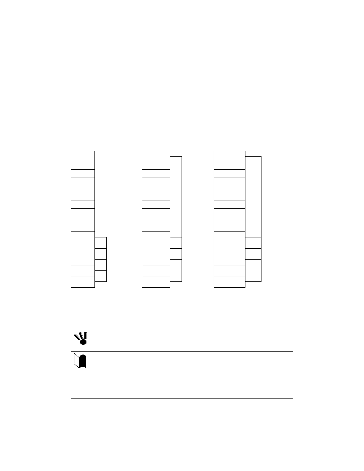
The diagram below presents an example of the hot spare operatio n
PDN14 Spare disk PDN14
PDN13 PDN13 PDN13
PDN12 PDN12 PDN12
PDN11 PDN11 PDN11
PDN10 PDN10 PDN10
PDN9 PDN9 PDN9
PDN8
PDN7 PDN7 PDN7
PDN6 PDN6 PDN6
PDN5 PDN5 PDN5
PDN4
PDN3
PDN2
PDN1
PDN0
Failure in PDN1 Recovery of data
→
LDN0 RAID5
PDN8
PDN4
PDN3
PDN2
PDN1
PDN0
in spare disk
→
LDN0 RAID5
* PDN (Physical Disk Number): Disk drive
LDN (Logical Disk Number): Logical Disk Number
PDN14
PDN8
PDN4
PDN3
PDN2
PDN1
PDN0
Replacement of PDN 1
LDN0 RAID5
Spare Disk
Do not move an y of the factory-installed disk drives into another slot.
The spare disk can operate properly only when it has a capacity and a
rotational speed equal to the defective disk drive.
If disk drives having different capacities and/or revolutions coexist, spare
disks of the different capacities and/or revolutions must be defined to manage
the disk drives clearly.
Up to 32 spare disks may be installed in the entire disk array unit.
9

2.2 Write Cache Feature
For RAID levels 5, 6, or 50, the performance of the disk array unit may decrease during the writing of
small amounts of data. This is because the previous data and parity data must be read to recalculate the
parity.
So, the disk array unit is equipped with cache memory. When write data is stored in the cache memory,
the disk array unit terminates the command processing and then writes the data to the disk drive,
improving the performance.
In general, if the power is shut down before the data saved in the cache memory is written to the disk
drive, the data in the cache memory will be lost. To prevent this, the disk array unit provides a battery
backup to the power supply to retain data in the cache memory.
The backup time using the Battery Backup Unit is restricted as follows:
The backup time of the battery backup unit depends on the capacity of the installed cache memory and
the service period of the battery. The following table shows the backup time when two battery backup
units are installed and they are both fully charged.
The following conditions are imposed to make the write cache preservation feature effective:
Two controllers, one or more battery backup units, and power supplies for the battery backup unit
(PS0 for BBU0, PS1 for BBU1) are installed and operating normally.
The battery backup units are fully charged.
If any of the conditions are not satisfied, the write cache preservation feature will not work properly.
The batteries installed in the battery bac kup unit are fu lly charged for about eight hours.
If the battery switch on battery backup unit is not turned on, the battery backup unit does not operate.
Cache memory capacity
4GB 96H 48H
8GB 72H 36H
16GB 48H 24H
* The battery backup time can be maintained by replacing the battery at intervals of 2.5 years
(with charge).
* The life expectancy of a battery is 5 years. However, if the pow er on/off sequence is required
everyday, the batteries a re exhausted faster. If so, the batteries should be replaced with
charge at intervals of 2.5 years.
Battery Back Up unit Service period
2 .5 years or under 2.5 to 5 years
10
2.3 Management Software
The S2900 Disk Array management software " NEC Storage Manager Base Product" (available
optionally included) can be used to allow the host system to display the resources in the disk array unit
in a real time mode.
NEC Storage Manager also enables you to set the following parameters through the host computer:
Setting of the RAID configuration (RAID 1, 5, 6, 10, 50, and hot spare disk)
Resetting of the RAID configuration
Maintenance of an error log
Before the di sk array unit can be used to store data, the license lock must be
released by using the license code provided with the NEC Storage BaseProduct.
11
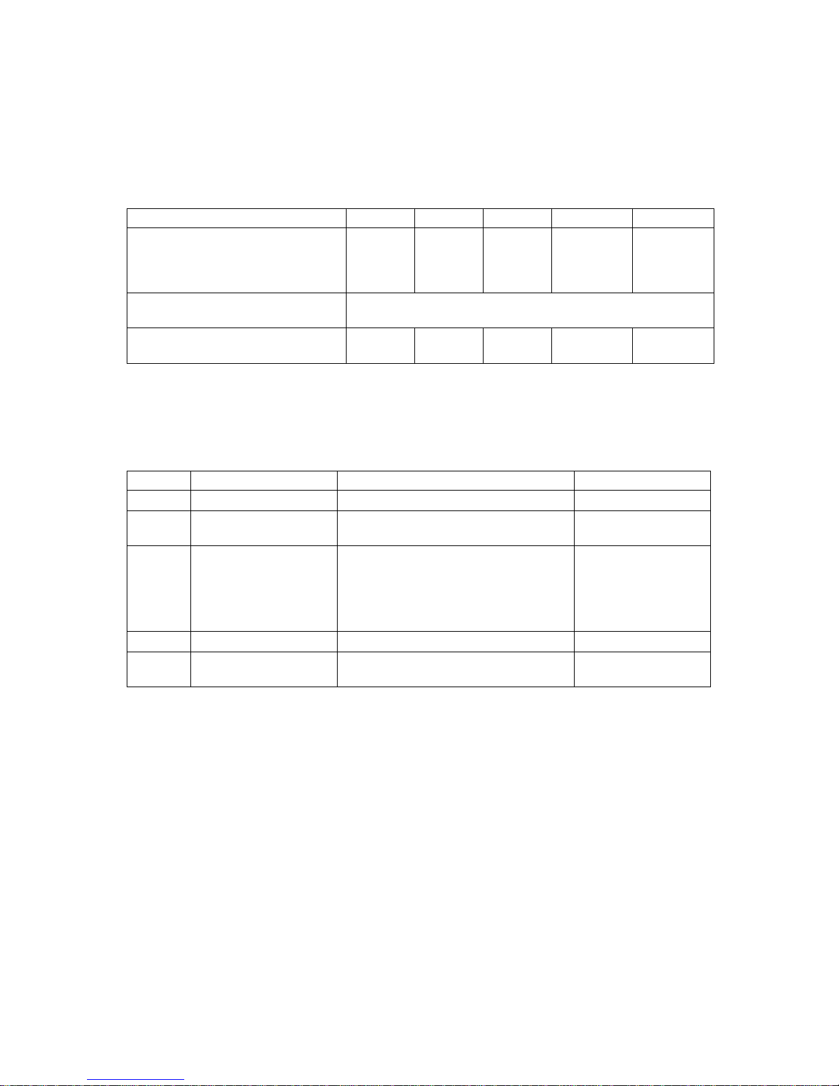
2.4 RAID Configuration
The RAID configuration in the disk array unit can be used in the combinations shown in the table
below.
RAID le vel RAID1 RAID5 RAID6 *1 RAID10 RAID50
2x2 6x2
Number of logical drives in
configuration
Number of logical drives per
subsystem
Storage capacity per logical drive
(When a 73-G B disk drive is used)
* A combination of disk drives of the same capacity and same rotation al speed is required for configuring logical
drives.
*1 Two modes (66%-mode and 80% mode) can be selected according to capacity efficiency.
1+1 4+1 6 to 240
1,024 maximum
71.6GB 286.4GB 286.4GB
to 13TB
3x2 7x2
4x2 8x2
5x2
143.2GB to
572.8GB
5x2, 5x4
572.8GB to
1145.6GB
The RAID levels have the following characteristics.
Level Function Advantage Disadvantage
RAID1 Mirroring High reliability High cost
RAID5 Striping of data and
redundant data
RAID6 Striping of data and
redundant data
RAID10 Striping of RAID-1 High-speed data read/write High cost
RAID50 Striping of RAID-5 High-speed data read
High capacity efficiency Low-speed data
writing
High reliability that allows continuous
operation even with multiple HDD
failures.
Capacity can be expanded for every
drive.
High capacity efficiency
Low-speed data
writing
High implementation
cost
12
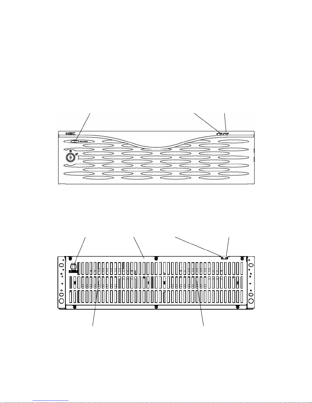
3. Names and Roles of Components
This chapter describes the names and functions of the components in the disk array unit.
3.1 Array Controller (Front)
(5) SHUTDOWN switch
(1) POWER LED (2) SERVICE LED
A front bezel is installed on the front face of the array controller as shown in the figure above.
The front bezel can be removed by releasing the lock with the accessory key and pulling out toward
you with your hands hooked on the both sides of the bezel. In this state, the accessory key cannot be
pulled out. To pull the key out from the front bezel, you must set the key at the lock position.
Removing the front bezel, you can view the battery cover shown in the figure below.
(5) SHUTDOWN switch (3) Battery cover
(1) POWER LED (2) SERVICE LED
(4) Battery Backup Unit (BBU0) (4) Battery Backup Unit (BBU1)
13
 Loading...