

NEC S2500, S1500, NF2500-SR40E, NF1500-SR40E User Manual
A
r
NEC Storage S2500
NF2500-SR40E
NEC Storage S1500
NF1500-SR40E
Disk Array Unit
User's Guide
NOTE:
Read this manual carefully before using the unit. Keep this
manual nearby as a handy reference and refer to the
"CAUTION" and "WARNING" statements whenever necessary.
NEC CONFIDENTIAL AND PROPRIETARY
ll rights reserved by NEC Corporation. This document must be
used solely for the purpose for which it was furnished by NEC
Corporation. No part of this document may be reproduced o
disclosed to others, in any form, without the prior written
permissio n of NEC Corporation.
856-850725-101-A

Trademarks
Microsoft, Windows, Windows NT , W indows 2000, and W indows Server 2003 are registered trademarks or
trademarks of Microsoft Corporation in the United States and other countries.
HP and HP-UX are registered trademarks of Hewlett-Pack ar d Compa ny of the United States.
Sun, Solaris, and StorEdge are tr ademarks or registered trademarks of Sun Microsystems, Inc. in the United
States and other countries.
Linux is a registered trademark or trademark of Linus Torvalds in the United States and other countries.
All other product, brand, or trade names used in this publication are the trademarks or registered trademarks of
their respective trademark owners.
Remarks
(1) No part of this manual may be photocopied in any form without prior written consent from NEC.
(2) The information in this manual is subject to change without notice.
(3) All possible efforts are being made to create this manual, but in the event that any technical or
editorial errors or omissions are found, contact your dealer.
(4) Save this manual in a convenient area even after you finished reading it.
(5) When transferring this unit to other person, be sure to transfer this manual also.
(6) NEC shall not be liable for any loss or lost profits from the use of this disk array unit regardless of
the item in (3).
(7) This unit is not intended to be installed into the installation or equipment associated with human
life, such a s medical equipment; nuclear installations or equipment, aerial and/or space
equipment, transportation installations and equipment and is to be installed into and to control the
installation or equipment requiring high reliability. If you use this unit for these installations,
equipment, or control systems, NEC shall not be liable for an accident leading to an injury or
death, fire, or social loss resulting from a breakdown of our product.
© NEC Corporation 2005
i
FEDERAL COMMUNICATIONS COMMISSION
RADIO FREQUENCY INTERFERENCE STATEMENT
NOTE: This equipment has been tested and found to comply with the limits for a Class A digital
device, pursuant to Part 15 of the FCC Rules. These limits are designed to provide reasonable
protection against harmful interference when the equipme nt is ope r ated i n a comme r cial environment.
This equipment generates, uses, and can radiate radio frequency energy and, if not installed and used
in accordance with the instruction manual, may cause harmful interference to radio communications.
Operation of this equipment in a residential area is likely to cause harmful interference in which case
the user will be required to correct the interference at the user’s own expense.
ii
Safety Precautions
Before using this unit, read this manual carefully and take proper precautions in order to use this unit
safely and correctly, avoiding the potential for any personal or property damage. Keep this manual
nearby for easy reference.
The following symbols are used in this man u al so t hat y ou can easily understand how to operate the
unit safely and correctly.
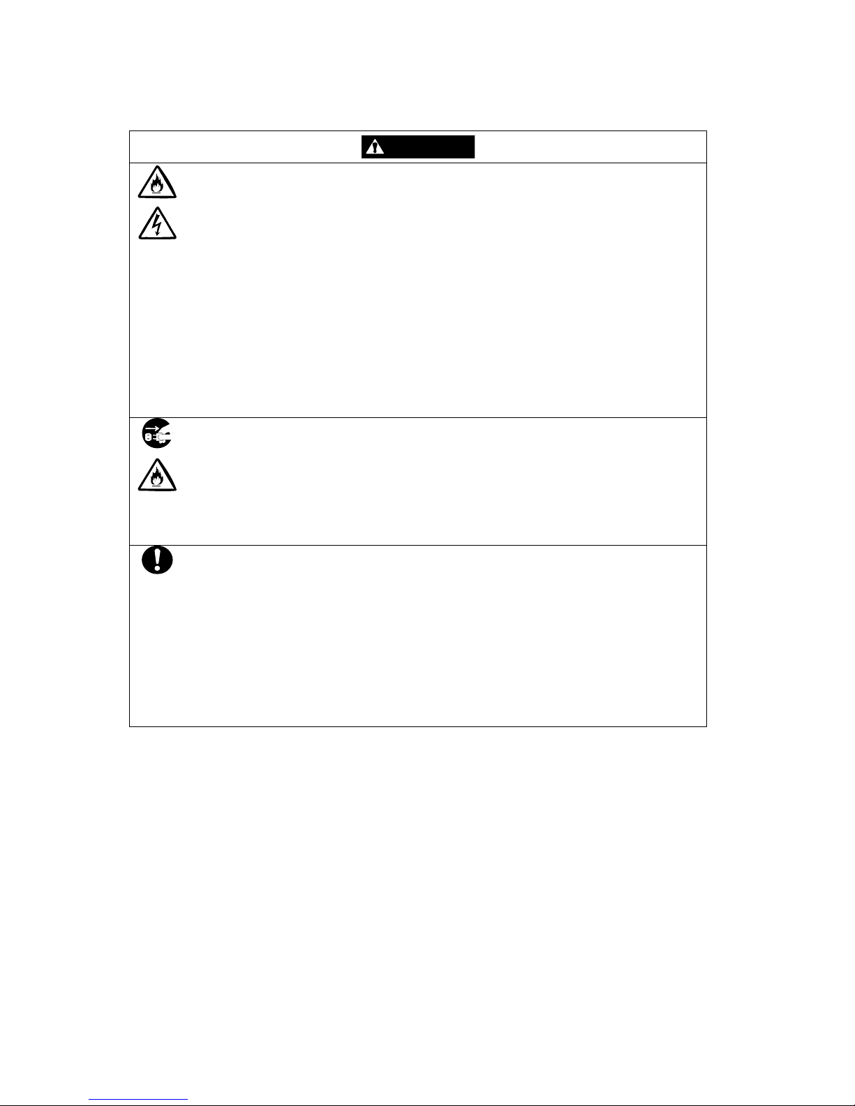
WARNING
CAUTION
Indicates that there is a risk of death or serious injury.
Indicates that there is a risk of burn or injury.
Risks and the necessary actions to reduce risks are indicated individually by the following symbols.
Indicates the risk of smoke emission or fire outbreak.
Indicates the risk of electric shock.
Indicates required general actions for operators.
Indicates instructions to pull out the plug of a power cord from outlet.
Indicates not i c e of ge ne r a l prohibition.
Indicates instructions to keep a device away from inflammable objects.
Indicates the danger of an injury due to harmful material.
iii
Notes on Use
The following includes information necessary for proper and safe operation of the disk array unit.
WARNING
• Do not use the disk array unit in an area of high humidity or water usage. If so, a
fault, electrical shock, or fire may occur.
• Do not use the disk array unit in an area where inflammable gas and/or
combustible substances are placed. If so, fire or explosion may occur.
• Do not overload AC outlets with power cords. If so, fire may occur.
• Do not put any heavy materials on a power cord. If so, the coating of the power
cord may be broken, fire may occur, and/or you may be electrically shocked.
• Do not install the disk array unit in a dirty or dusty environment. Remove any dust
adhering to AC outlets and the plugs of power cords. Should any dust remain
adhering to an AC outlet and/or plug, fire may occur.
• Do not connect the plug of a power cord to an AC outlet with a wet hand. If so, you
may be electrically shocked.
• While the disk array unit NFx500-SR40E can accept the power in the range of 100
- 240 VAC (50/60 Hz), the power cord shipped with the disk array unit can only
accept 100 – 120 VAC. Use 100 – 120 VAC (50/60 Hz) when the included power
cord is used. Using power of a different voltage may cause electric shock, smoke,
and/or fire to occur.
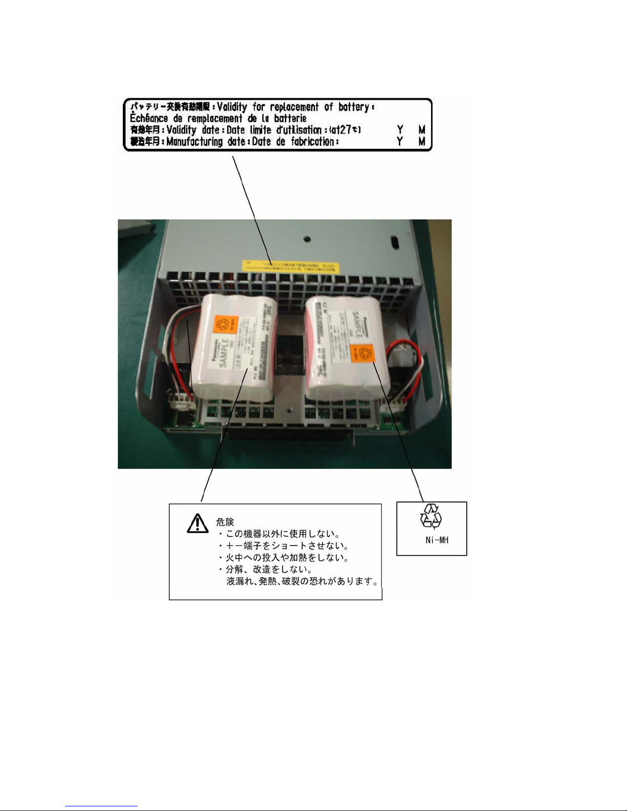
• The controller of the disk array unit contains a lithium battery. Do not remove the
lithium battery. The lithium battery may explode when it is brought close to fire or
immersed in water. Dispose of the controller according to local ordinances.
Contact your local government for details.
• If the disk array unit does not operate normally due to the life of the lithium
batteries, contact your service representative. Do not disassemble the controller,
or replace or charge battery by yourself.
iv
CAUTION
• Do not install the disk array unit and the host systems in an unsafe or unstable
manner. If so, damage may occur to the unit and/or you may be personally injured.
• Do not install the disk array unit and the power cords in an area with direct sunshine
or near any apparatus generating heat such as a heater. If so, a fault may occur.
Further, the insulating coating of the power cord may be melted causing fire or
electric shock to occur.
• Insert the plug of a power cord to an AC outlet securely. Tightly secure the DC
power cable with the screw. Any power cord shall be routed with sufficient margin to
avoid excess strain from being applied to the plugs of the power cord or the power
cord itself. If a power cord is removed from the AC outlet during operation, data may
be lost and/or a fault may occur.
• To prevent electric shocks, connect all power cords to an AC outlet with earth
grounding. Connection of the earth line to a gas pipe is extremely dangerous. Never
do it.
• Before connecting or removing a peripheral device from the disk array unit, turn off
all the power switches of the disk array unit and peripherals and pull out the power
cords from the AC outlets or distribution board. If not, some units may be damaged
and/or you may be electrically shocked.
• To carry or reinstall the disk array unit, disconnect all cables and power cords
beforehand. If not, some units may be damaged, you may be electrically shocked,
and/or a fire may occur.
• Handle optical fibers carefully and gently.
• The minimum bending radius of optical fiber shall be 30 mm.
• Dust and/or dirt may attenuate the optical power of optical fiber to cause data errors
to occur. Clean any optical fiber cable whenever it is inserted into the mating
connector with the following procedure. Never clean a connector in which light is
present in the fiber.
1. Use a lint-free "wipe" that has been dipped into alcohol (use of 99% reagentgrade alcohol is recommended).
2. Followed immediately by a dry lint-free wipe.
3. And finally to blow-dry using a can of clean, compressed air
v

To install the unit in a rack, observe the following guidelines.
1. Temperature – If installed in a rack, consideration should be given to installing the
equipment in an environment compatible with the manufacturer's recommended
ambient temperature (TMRA).
2. Reduced Air Flow – Installation in a rack should be such that the amount of air flow
required for safe operation of the equipm ent is not compromised.
3. Mechanical loading – Mounting of the equipment in the rack should be such that a
hazardous condition is not achieved due to uneven mechanical loading.
4. Circuit Overloading – Consideration should be given to the connection of the
equipment to the supply circuit and the effect that overloading the circuits might
have on overcurrent protection and supply wiring. Appropriate consideration of
equipment nameplate ratings should be used when addressing this concern.
5. Reliable Grounding – Reliable grounding of rack-mounted equipment should be
maintained. Particular attention should be given to supply connections other than
direct conn ections to the branch circuit (e.g., use of power strips).
vi
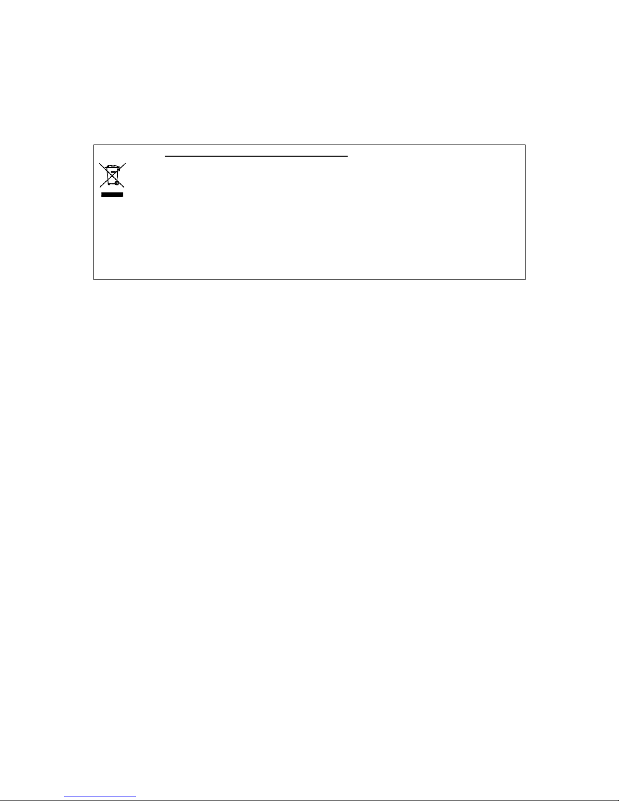
Notes on Disposal
Disposing of your used NEC product
In the European Union
EU-wide legislation as implemented in each Member State requires that used electrical and
electronic products carrying the mark (Left) must be disposed of separately from normal
household waste. The equipme nt with this mark may in c l ud e electrical ac c e s s o ri e s
(e.g. memory cards). When disposing of used NEC products, you should comply with
applicable legislation or such terms which may have been agreed between NEC and
your company regarding used products. This mark on electrical and electronic
products only applies to the current European Union Member States.
Outside the European Union
If you wish to dispose of used electrical and electronic products outside the European
Union, please contact your local authority and ask for the correct method of disposal.
vii
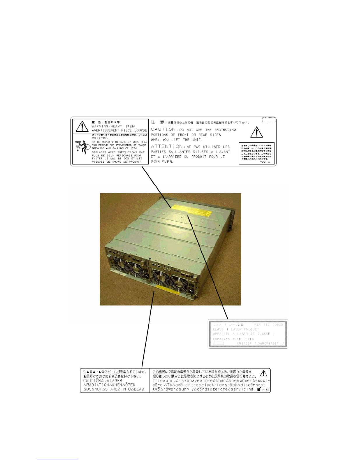
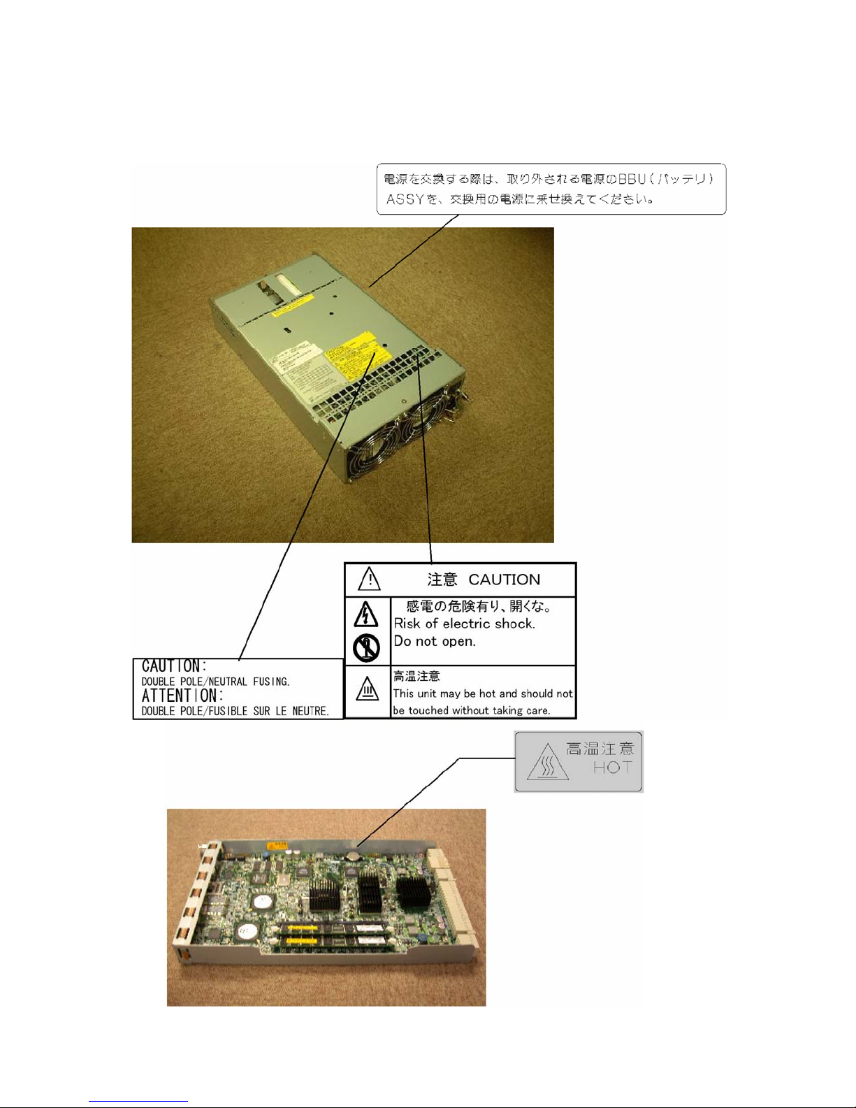
Indication on Safety
The warning label is attached to components (or a location in their vicinity) that pose a possible
danger or to inform the user that a hazardous situation may arise when operating the disk array unit.
(Do not intentionally remove or damage any of the labels.)
If you find any labels totally/partially removed or illegible due to damage, contact your sales
representative.
viii
Power supply for NFx500-SR40E
ix
x
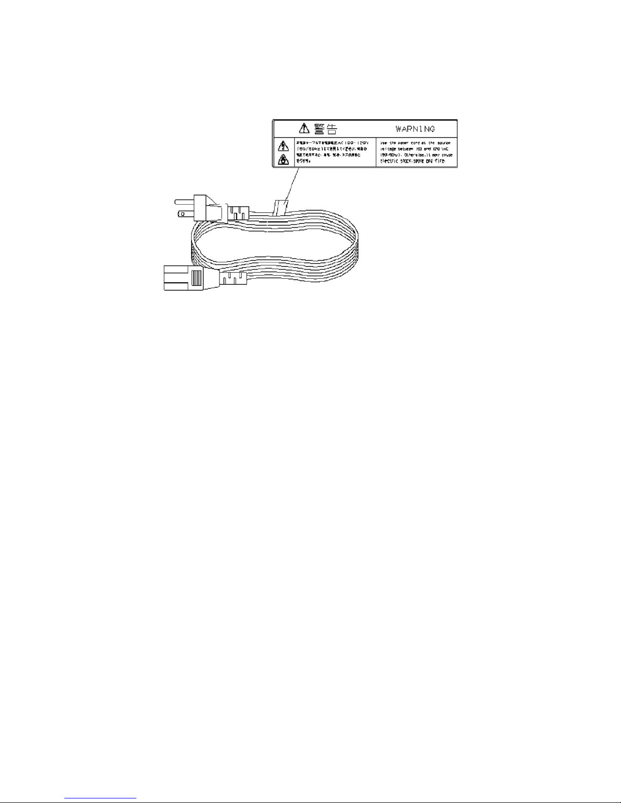
AC Power Cord
xi

Preface
Thank you very mu ch for your purchase of th i s NF x 500-SR40E.dis k ar ray unit. This manual is
intended to enable you to correctly use the disk array unit
Before using the disk array unit, you might also read the manuals of several other devices including
any of the NEC Express5800 series, the NX7000/NX7700i series or CX5000 series computers, any
FC-AL SCSI connection mechanism or FibreChannel controller that is to be connected with the disk
array unit and the manual of the operating system in use.
The NEC Storage BaseProduct software needs to be purchased se pa r ately for using the disk array unit.
The following options are available for the disk array unit:
Options for NF2500-SR40E
Cache memory NF2500-SC01E
Options for NF2500-SR40E/NF1500-SR40E
FC disk enclosure NF2500-SE42E
SATA disk enclosure NF2500-SE82E
FC disk drive ( 73GB/10Krpm) NF2500-SM413E
FC disk drive (147GB/10Krpm) NF2500-SM414E
FC disk drive (300GB/10Krpm) NF2500-SM415E
FC disk drive ( 73GB/15Krpm) NF2500-SM423E
FC disk drive (147GB/15Krpm) NF2500-SM424E
SATA disk drive (400GB/7200rpm) NF2500-SM802E
Options for NF1500-SR40E
Cache memory NF1500-SC04E
Option battery NF1500-SZ01E
To install the disk array unit in a non-standard rack:
Rack mount kit NF9100-SK01E, NF9100-SK02E, and NF9100-SK03E
After reading this manual, keep it nearby for use as a handy reference.
First edition, December 2005
xii
Pre-Installation Checklist
(1) Unpacking
Open the package and remove the disk array unit and accessories from the package carefully. The disk
array unit is very heavy. Accordingly, if two people or less lift the unit, personal injury may occur. To
remove the disk array unit from the package, more than three people should always support the bottom
of the unit without holding the power supply and the projections of the controller.
The package is specially designed for conveyance of a precision device. Do not dispose of the package
because it is required to return the disk array unit to the factory for any repair.
(2) Inspection
After unpacking, check that all the components listed in the table below are provided. If any of the
components are missing, contact your sales representative. Next, inspect the disk array unit and
accessories. If any of the components are damaged, contact your sales representative.
No. Product name Remarks Qty
1 NEC Storage S2500/S1500 S2500: NF2500-SR40E
S1500: NF1500-SR40E
Note: An SD card is mounted only on
CONT0.
2 Power cord Length 3 m (for 100 VAC) 2
3 Front mask With security key 1
4 User's Guide This document 1
5 Rack mount kit For NEC Storage rack (L and R) 1
6 Software
7 Packing list 1
NEC Storage S2500/S1500 Disk Array
control program CD
1
1
xiii
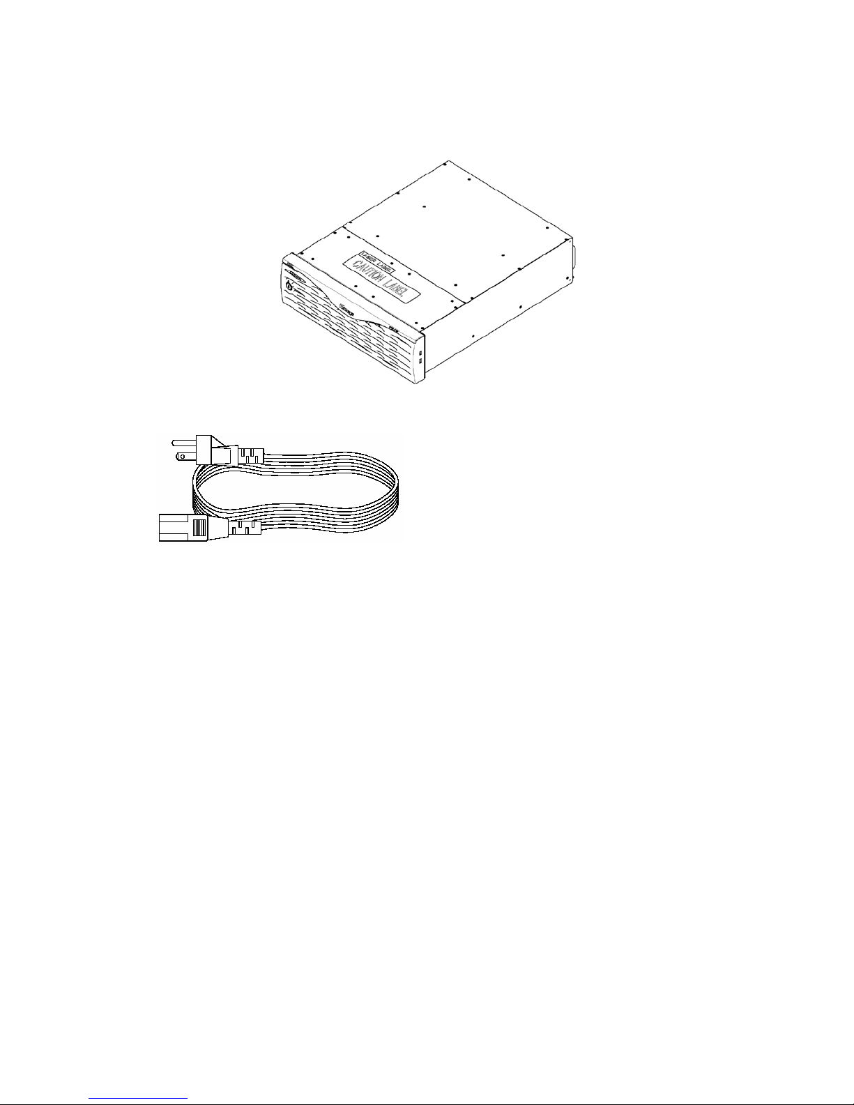
(1) NEC Storage S2500/S1500 disk array unit
(The figure above shows the unit with the front mask installed.)
(2) Power cord (x2), or
(3) Front mask (4) User's Guide
(5) Rack-mount kit (6) Software
(7) Packing list
xiv
Legend
Symbols in the Text
This User's Guide uses the following symbols to indicate improper handling which may cause the disk
array unit to become defective.
Symbol Description
If the description is ignored when handling the disk array unit, the unit may
become defective, some software used in the unit may be damaged, and/or
the data created by the user may become corrupted.
This User's Guide also uses the following symbol.
Symbol Description
This User's Guide uses the following terms to indicate specific devices.
If the description is ignored when handling the disk array unit, the unit may
become defective and/or some software used in the unit may not operate
properly.
Supplement of the text
Disk array unit Indicates the NF2500-SR40E and/or the NF1500-SR40E .
FC disk enclosure
SATA disk enclosure
Disk drive Indicates the hard disk drive with dedicated tray.
Dummy tray
Host system
Host bus adapter
Indicates the additional FC disk enclosure NF2500-SE42E
(sold separately).
Indicates the additional SATA disk enclosure NF2500-SE82E
(sold separately).
Indicates the dedicated tray only, with no hard disk drive
installed.
Indicates the NEC Express5800, NX 7000/NX7700i , or
CX5000 series.
Indicates the FibreChannel controller for the NEC
Express5800 or CX5000 series, or the FC-AL SCSI connection
mechanism for the NX7000/NX7700i series.
xv

Contents
1. Notes on the Installation and Handling of the Disk Array Unit.............................1-1
1.1 Note on Carrying the Disk Array Unit............................. .... ... .... .......................................1-1
1.2 Environmental Considerations for the Use of the Disk Array Unit...................................1-2
1.3 Installation and Connection of the Disk Array Unit..........................................................1-3
1.4 Notes on Use of the Disk Array Unit........................ ... .... .... ... . ... ... .... .... ... .... ... .... ... .... .... ...1-4
1.5 Routine Inspection of theDisk Array Unit.........................................................................1-5
1.6 Notes on Storage or Conveyance of theDisk Array Unit...................................................1-6
2. Features of the Disk Array Unit...............................................................................2-1
2.1 Hot Spare Feature..............................................................................................................2-2
2.2 Write Cache Feature ..........................................................................................................2-3
2.3 Software Products..............................................................................................................2-4
2.4 Management Software.......................................................................................................2-4
2.5 Updating of Control Software....................................................... .... ... .... .... ... .... .... ... .... ...2-5
2.6 RAID Configuration..........................................................................................................2-5
3. Names and Roles of Sections .................................................................................3-1
3.1 Front View.........................................................................................................................3-1
3.2 Rear View..........................................................................................................................3-3
3.3 Power Supply ....................................................................................................................3-5
3.4 Controller...........................................................................................................................3-7
3.5 Battery Backup Unit........................................................................................................3-10
4. Installation and Connection Procedures................................................................4-1
4.1 Installation and Connection Procedures........ .... ... .... ... .... .... ....... ... .... ... .... .... ... .... .... ... .... ...4-1
5. Connection of Disk Array Unit.................................................................................5-1
5.1 Notes on Connection of the Disk Array Unit ....................................................................5-2
5.2 Connection of theDisk Array Unit.......................................... .... ... .... ... .... .........................5-3
5.3 Connection of the Disk Array Unit as Additional Unit......................................................5-7
5.4 Connection of theEthernet Cable................................................ ... .... ... .... .... ... .... .... ... .... . 5-11
5.5 Connection of thePower Cords............................. .... ... .... .... ... .... ... .... .... ... .... ... .... ... .... .... .5-12
6. Addition of Optional Devices...................................................................................6-1
6.1 Addition of Disk Drives...................................................................................... .... ... .... ...6-1
6.2 Addition of a Disk Enclosure........................................................ .... .... ... .... .....................6-7
6.3 Addition of Cache Memory Modules..............................................................................6-15
6.4 Addition of theOptional Battery......................................................................................6-20
7. Handling of the Disk Array Unit...............................................................................7-1
7.1 Notes on Handling of theDisk Array Unit.........................................................................7-1
7.2 Power On/Off of the Disk Array Unit....................................................... .... ... .... .... ... .... ...7-2
7.3 LD (Logical Disk) Setting Procedure................................................................................7-6
7.4 Spare Disk Setting Procedure...... .... ... .... ... .... .... ... .... ... .... ....... .... ... .... .... ... .... ... .... ... .... .... ...7-6
8. Troubleshooting........................................................................................................ 8-1
8.1 Countermeasures Taken when Occurrence of a Fault is Suspected...................................8-2
xvi

8.2 Indication at Occurrence of Fault..................... .... .... ... .... .... ... .... ... .... .... ... .... ... .... ... .... .......8-4
8.3 Controller Failure ..............................................................................................................8-5
8.4 Power Supply Failure ........................................................................................................8-9
8.5 Battery Backup Unit Failure............................................................................................8-14
8.6 Disk Drive Failure....................... .... ... .... ... .... .... ... .... ... .... ... .... .... ... .... .... ... .... ... .... ... .... .....8-15
8.7 Model and Serial Numbers..............................................................................................8-18
8.8 Computer Virus ...............................................................................................................8-20
8.9 Contacting Technical Supportl ........................................................................................8-20
8.10 Service and Support.........................................................................................................8-20
8.11 Unit Life/Repair Service Period......................................................................................8-21
8.12 Disposal of Disk Array Unit............................................................................................8-21
9. Product Specification............................................................................................... 9-1
9.1 Basic Specifications of theDisk Array Unit... ... .... .... ... .... ... .... .... ... .... ... .... .... ... .... ... ...........9-1
9.2 Optional Components........................................................................................................9-1
9.2.1 Options for NEC Storage S2500................................................................................9-1
9.2.2 Options for NEC Storage S1500................................................................................9-1
9.2.3 Options common to NEC Storage S2500/S1500..................................... .... .... ... .... ...9-1
9.2.4 Accessories common to NEC Storage Series ............................................................9-2
9.3 Environmental Conditions.................................................................................................9-3
9.4 Power Specifications .........................................................................................................9-3
9.5 External Dimensions and Weight......................................................................................9-3
9.6 Life Expectancies of Components.....................................................................................9-3
Appendix A Features of Disk Array Unit................................................................ A-1
1. Battery Backup ........................................................................................................ A-1
2. Repair Time .............................................................................................................. A-1
3. Logical Disk Capacity.............................................................................................. A-2
3.1 Arbitrary Logical Disk Capacity ......................................................................................A-2
3.2 Maximum Logical Disk Capacity.....................................................................................A-2
4. Access Control ........................................................................................................ A-2
4.1 Port Mode.........................................................................................................................A-3
4.2 WWn Mode ......................................................................................................................A-3
5. Dynamic Data Replication....................................................................................... A-3
6. Miscellaneous Settings ........................................................................................... A-4
7. Various Default Values ............................................................................................ A-4
8. Notes on Use of DynamicDataReplication............................................................ A-4
9. Setting of OS Type................................................................................................... A-5
10. Software Products............................................................................................ A-5
11. Updating of Control Software.......................................................................... A-6
12. Snap Shot.......................................................................................................... A-6
12.1 Note on Using Snap Shot .................................................................................................A-7
Appendix B Installation Procedure......................................................................... B-1
1. Creation of Logical Disks........................................................................................ B-1
xvii

1.1 Binding Logical Disk ......................... .... ... .... .... ... .... ... .... .... ... .... ... .... ... .... ........................ B-1
Appendix C Use of a Maintenance PC ................................................................... C-1
1. Initialization by a Maintenance PC......................................................................... C-1
1.1 Connection of a Maintenance PC..................... .... .... ... .... .... ... .... ... .... .... ... .... ... ................. C-1
1.2 Configuration.................................................................................................................... C-4
1.2.1 Port Configuration .................................................................................................... C-4
1.2.2 FC Port Configuration .............................................................................................. C-5
1.2.3 Resource Configuration............................................................................................ C-8
2. Confirmation of Unit Setup....................................................................................C-11
2.1 Activation on Modification of FC Port Configuration................................................... C-11
2.2 Confirmation of FC Port Configuration ......................................................................... C-12
2.3 Confirmation of Resource Configuration....................................................................... C-13
Appendix D Installing Unit on Rack........................................................................ D-1
1. Installing Rack-mount Kit (Accessory) in a NEC Storage Rack.......................... D-1
1.1 Installing Unit on New Universal Rack Mount Kit.......................................................... D-1
1.2 Installing Unit on Universal Rack Mount Kit ..................................................................D-5
1.2.1 Angle Hole Fitting Rail............................................................................................. D-6
1.2.2 Round Hole Fitting Rail..........................................................................................D-12
2. Installing Unit in a HP Rack.................................................................................. D-18
2.1 Installation of Rails.........................................................................................................D-18
2.2 Installation of Rack Nuts................................................................................................D-22
2.3 Installation of Unit..........................................................................................................D-23
3. Installing Unit in a Sun StorEdge Rack................................................................ D-24
3.1 Installation of Rails.........................................................................................................D-24
3.2 Installation of Unit..........................................................................................................D-26
4. Installing Unit in an Express Old-type Rack ....................................................... D-27
4.1 Installing the Rack Mount Kit............ .... ... .... .... ... .... ... .... .... ... .... ... .... ... .... .... ... .... .... ... .... D-28
4.2 Installation of Unit..........................................................................................................D-29
5. Cable Wiring........................................................................................................... D-30
Notes on the Installation and Handling of the Disk Array
Unit
Note on Carrying Disk Array Unit
Be sure to hold the bottom the disk array unit when carrying it.
Hold the front or side bottom of the disk array unit if possible.
xviii
xix
Environmental Considerations for the Use of Disk Array Unit
During installation of the disk array unit, take into account the following considerations on the
location, room temperature, space required for handling, ventilation, and other conditions.
• Install the disk array unit indoors.
Do not expose the disk array unit to direct sunlight. Use a window shade or
curtain to block sunlight on the unit if necessary.
• Install the disk array unit on a lev el surface of sufficient streng th. In additio n, do
not apply shocks and/or vibrations to the disk array unit. If so, some
components may be damaged causing the disk array unit to become defective
and/or personal injury.
• Install the disk array unit in an area under the following conditions; temperature
range between 5°C - 40°C and a humidity range between 10% - 80% (without
condensation).
• Do not install the disk array i n an area with running water or oils, areas
contaminated by liquids such as water and oil, steam, areas with steam or
other high moisture content. If so, a fault or electrical shock may occur
• Do not install the disk array in an area near the emission of chemical steam or
an area where the disk array may come in contact with an inflammable
substance. If so, a fault, fire, or explosion may occur.
• Do not install the disk array unit in dirty or dusty environments. If so, a fault
may occur.
• Do not install the disk array unit in an area with direct sunshine or near fire or
an apparatus generating heat such as stove. If so, a fault or deformation may
occur.
• Do not install the disk array unit near TV, radio, or cordless telephones as
some interference may appear in the TV, radio, or cordless telephone.
• Do not use cellular phones near the disk array unit. If so, a fault may occur.
• Do not install the disk array unit near any device generating a strong magnetic
field, such as audio speakers. If so, a fault may occur.
• Do not install the disk array unit so that the ventilating holes on the front and
rear faces are blocked. If so, heat generation and/or fault may occur.
xx

Installation and Connection of Disk Array Unit
WARNING
• Do not use the disk array unit in an area of high humidity or where water
usage occurs. If so, a fault, electrical shock, or fire may occur.
• Do not use the disk array unit in an area where inflammable gas and/or
combustible materials are placed. If so, fire or explosion may occur.
• Do not install the disk array unit in a dirty or dusty environment. Remove
any dust adhering to AC outlets and the plugs of power cords. If dust
remains adhering to an AC outlet and/or plug, fire may occur.
• Do not overload AC outlets with power cords. If so, fire may occur.
• Do not put heavy materials on a power cord. If so, the insulating coating of
the power cord may be broken, fire may occur, and/or you may be
electrically shocked.
• Do not connect the plug of a power cord to an AC outlet or distribution
board with a wet hand. If so, you may be electrically shocked.
CAUTION
• Make sure to disconnect all power cords and cables before relocating the
disk array unit. If not, a malfunction of the system, an electric shock and/or
fire may occur.
• While the disk array unit can accept power in the range of 100 - 240 VAC
(50/60 Hz), the power cord shipped with the disk array unit can only accept
100 – 120 VAC. Use 100 – 120 VAC (50/60 Hz) when the enclosed power
cord is used. Using power of different voltage may cause electric shock,
smoke, and/o r f i r e t o occur.
• Do not install the disk array unit and the power cords in an area with direct
sunshine or near any apparatus generating heat such as a heater. If so, a
fault may occur. Further, the insulating coating of the power cord may be
damaged causing fire or electric shock to occur.
• The disk array unit weighs 34 kg or more. Hold the disk array unit or disk
enclosure firmly using at least three people to carry it. Carrying the devices
by two or less people may cause personal injury.
• Select a location where the disk array unit can be connected to the AC
outlet or distribution board by using the attached power cord, without using
an extension cord,
• Insert the plug of a power cord into an AC outlet securely. If some clearance
remains between the plug of the power cord and the AC outlet, dust may
enter into the clearance. This then may cause fire to occur.
• Provide sufficient margins for the cables connected to the disk array unit so
that entanglement is not an issue. Avoid placing unnecessary strain on
power plugs and FC connectors.
• Do not crimp cables connected to the disk array unit. If so, a fault or fire
may occur.
xxi
• Use the cables provided by NEC as those connected to the disk array unit
and check the destinations to which the cables are connected. In addition,
always secure power cords and FC cables when they are connected.
• Use a power source independent from any TV or radio. Otherwise,
interference may be generated.
• To connect a cable to the mating connector, make sure that the connector
of the cable is not damaged and any pins are not bent. Using a cable not
approved by NEC or a damaged cable may cause a fault or fire to occur.
• To disconnect a cable from the mating connector, always hold the
connector of the cable. Do not pull the cable itself to disconnect it.
Notes on Use of the Disk Array Unit
• Do not let any animals (pets) or children touch the cables connected to the
disk array unit. Pulling the cable may cause the unit to fall down, resulting in
failure of the unit or personal injury.
• Do not let any liquid such as water into the disk array unit. If so, you may be
electrically shocked or the unit may become defective. If some liquid does
enter into the disk array unit, immediately turn off the power, unplug the
power cord from AC outlet or distribution board, and contact your sales
representative or maintenance engineer. If the disk array unit seems dry,
remember, only a small amount of liquid may cause the unit to become
defective.
• Do not let any foreign substances such as paperclips or screws into the disk
array unit through the ventilating holes on the front or rear face. If so, a fault
may occur.
• Do not disassemble or modify the disk array unit in any way. If so, a fault or
electrical shock may occur. And, your warranty will be voided.
• If the disk array unit will not be used for a long period of time, disconnect the
plugs of the power cords from the AC outlet or distribution board for safety.
• It is advised that you disconnect the power plug from the outlet or
distribution board when a thunderstorm is approaching. If it starts
thundering before you disconnect the power plug, do not touch any part of
the unit including the cables. If any failure is found later, contact your sales
representative.
xxii
Routine Inspection of the Disk Array Unit
CAUTION
• To clean the disk array unit, always turn off the power and also disconnect
the plugs of the power cord from AC outlets. If not, you may be electrically
shocked.
• If a surface of the disk array unit becomes dirty, wipe the surface lightly with
a soft cloth. Wiping the surface by using chemicals such as benzene and
thinner, or other volatile chemicals, may cause the surface to become
deformed or discolored. In addition, note that spraying insecticide on a
surface may cause the surface to be deformed or discolored.
•
• It is recommended to clean the inside of the disk array unit periodically. This
is because dust may accumulate.
Contact your sales representative or maintenance engineer for the cleaning
of the inside of the disk array unit.
Users must not disassemble and/or repair the disk array unit as this is
dangerous.
• Do not use any battery backup unit exceeding its service life. If so, a fault or
fire may occur.
xxiii
Notes on the Storage or Moving of the Disk Array Unit
• Do not store the disk array unit in an area where the temperature may
increase extremely or the temperature difference between the warm and
cold states is considerably large. In addition, do not store the disk array unit
in an area with high humidity or dust.
• Note that foreign substances such as water and metal should be prevented
from entering into the disk array unit during storage. Using the disk array
unit with any foreign substance inside may cause a fault, electrical shock, or
fire to occur.
• During storage, do not put any materials on the disk array unit and do not
place the disk array unit in an environment where the unit may fall or be
dropped.
• To use the disk array unit after storage for longer than six months, it is
recommended that you contact your sales representative or maintenance
engineer for inspection and/or repair.
• The disk array unit weighs 34 kg or more. Hold the disk array unit firmly
using at least three people to carry it. Carrying the device by two or less
people may cause personal injury.
• When transporting the unit, make sure to package the disk array unit with
the packing material that shipped with the disk array unit. If any other
packing materials are used, vibration or shock generated during
transportation may cause a malfunction of the unit.
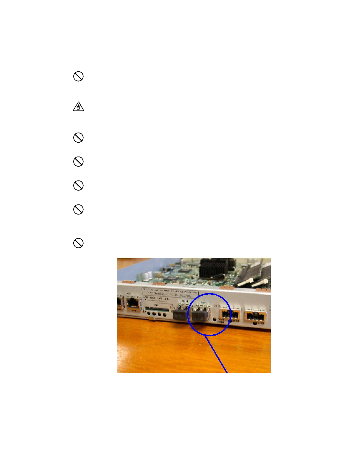
• During storage and transporting, attach the dust proof cover to the FC
connectors to prevent dust sticking. (See the figure below)
Features of the Disk Array Unit
This disk array unit has the following features.
xxiv
Dust proof cover
The NFx500-SR40E is a high-performance disk array unit designed for use with the NEC
Express5800 (Windows 2000 /Windows Server 2003 / Turbolinux 7 Server / RedHat Linux 7.2 /
Miracle Linux Standard Edition 2.1 / RedHat Enterprise Linux AS 2.1 / RedHat Enterprise Linux ES
2.1), NX7000/NX7700i (HP-UX), and CX5000 (Solaris) systems.
* Ask your sales representative for non-NEC servers (hosts) which are supported and compatible
operating systems.
The storage capacity of this disk array unit can be easily expanded by installing an additional FC disk
drive (optional) into the expansion slot of the disk array unit.
Expansion of the storage capacity of the disk array unit of is also possible by adding an additional FC
or SATA disk enclosure (optional) to the disk array unit.
The disk array unit supports RAID types 1, 5, 6, 10 and 50. If a fault occurs in a single disk drive (2
disk drives for RAID type 6), the disk array unit will continue the operation without loss of data.
Any defective disk drive can be replaced with a new one without system shutdown. Further, the disk
array unit has an auto repair feature which automatically starts data recovery after the replacement of
the defective disk drive.
If a single disk drive is specified as the spare disk, the data in the defective disk drive can be
immediately recovered in the spare disk. The use of this hot spare feature as well as the auto repair
feature allows the data in the defective disk drive to be automatically recovered in the spare disk as
soon as a disk drive becomes defective. This improves the system reliability.
The disk array unit has a cache memory data hold function when us ing the battery backup unit (BBU).
This function allows comfortable high-speed data processing to be done with high reliability.
Further, owing to the redundant configuration of the controller, fan, power supply, and battery backup
unit as well as the spare disk drive, high availability is achieved.
See Section 9.2 "Optional Components" for the product names and part numbers of options.
The above features of the disk array unit are effective only for hardware failures
(e.g., the hard disk is physically damaged or inoperative). Any software failure
(e.g., the data is lost or rewritten due to program excursion) is not covered by
these features. Should a software failure occur, the system could seriously be
damaged. To minimize the damage, be sure to back up the data periodically.
xxv
Hot Spare Feature
p
Spare disks can be installed in the disk array unit. If a disk drive becomes defective, the data in the
defective disk drive is recovered in the spare disk. After the data recovery, the disk drive operates
normally if another disk drive becomes defective.
A defective disk drive can be replaced without turning off the power of the disk array unit.
With the shipping default, if the spare disk replaces a disk drive that has become defective and the
spare is replaced with a new drive, the replaceme nt disk dr ive wor k s as a spar e di sk dr ive .
The data can also be recovered in another other disk enclosure.
Example of hot spare operation (LDN0 RAID5)
PDN14 Spare disk PDN14 PDN14
PDN13 PDN13 PDN13
PDN12 PDN12 PDN12
PDN11 PDN11 PDN11
PDN10 PDN10 PDN10
PDN9 PDN9 PDN9
PDN8
PDN7 PDN7 PDN7
PDN6 PDN6 PDN6
PDN5 PDN5 PDN5
PDN4 PDN4 PDN4
PDN3 PDN3 PDN3
PDN2
PDN1 PDN1 PDN1
PDN0 PDN0 PDN0
Failure in PDN1 Recovery of data
⇒
LDN0 RAID5
PDN8
PDN2
in spare disk
⇒
LDN0 RAID5
PDN8
⇐
LDN0 RAID5
S
are Disk
PDN2
Replacement of PDN 1
PDN1 works as a spare disk
* PDN: Physical Disk Number
LDN: Logical Disk Number
Do not move any of the factory-installed disk drives into another slot.
The spare disk can operate only when it has a capacity and a revolution
equal to the defected disk drive.
If disk drives having different capacities and/or revolutions coexist, spare
disks of the dif f e r ent c a pacities and/or r evolutions must be de f i ned to manage
the disk drives clearly.
Up to 32 spare disks may be installed in the entire disk array unit.
xxvi
Write Cache Feature
For RAID type 5, 6, or 50, the performance of the disk array unit may be decreased during the writing
of a small amount of data. This is because the previous data and parity data must be read to recalculate
the parity.
This disk array unit is equipped with cache memory. When write data is stored in the cache memory,
the disk array unit terminates the command processing and then writes the cached data to the disk
drive, improving the performance.
The cache memory is backed up with the battery backup unit. To increase data security,
an uninterruptible power supply (UPS) should also be used.
In general, if the power is shut down before the data saved in the cache memory is written to disk
drive, the data in the cache memory will be lost. To prevent this, the disk array unit featur es a batte ry
backup unit installed in the power supply to retain data in the cache memory.
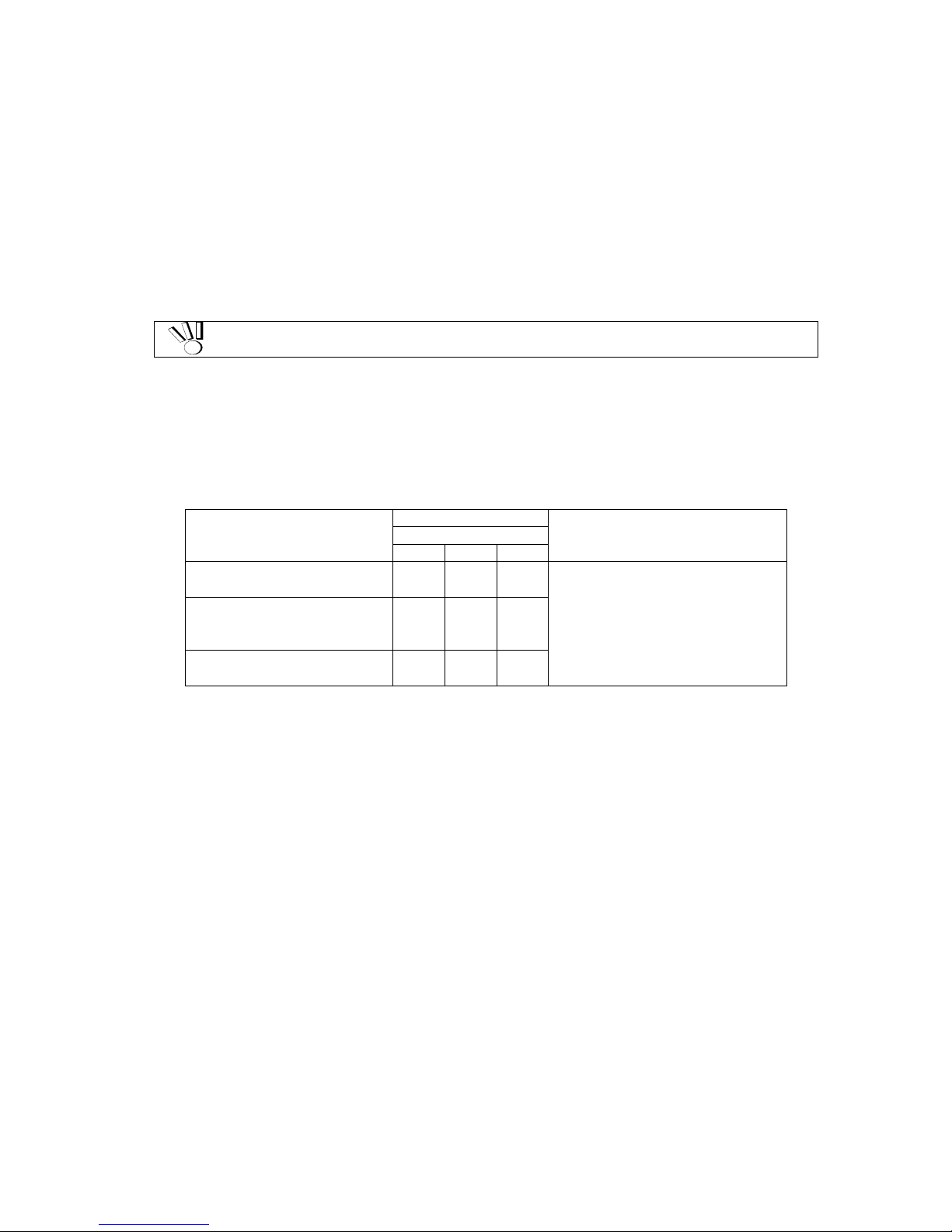
The backup time of the battery backup unit depends on the number of battery backup units installed.
The following table shows the backup time when the battery backup units are installed and they are
fully charged.
Number of Battery Backup
Units Installed
Standard configuration
(S1500)
Expanded configuration with
optional batteries
(S1500)
Standard configuration
(S2500)
* If the ambient temperature or backup frequency exceeds the conditions described
above, the battery back units need to be replaced (not a warranty replacement) before
they reach their service life of 5 years. Ask your NEC sales representative for the
relationship between the operation mode and the life of a battery backup unit.
Period of Service
Up to 5 years
2GB 4GB 8GB
24H 24H –
72H 48H –
– 72H 36H
Operating Conditions
Ambient temperature: @25ºC
Backup frequency: Once a week
16-hour discharging (power-off)
The following conditions are necessary to make the write cach e f eatur e effective:
The disk array unit will operate normally with the following components installed:
– 2 controllers (or 1 controller if you have enabled Write Cache from the maintenance PC)
– 1 or mor e power supplie s
– 1 or more battery backup units installed in the power supply or power supplies above
(BBU0 for PS0 and BBU1 for PS1)
The battery backup units are fully charged.
If any of the conditions is not satisfied, the write cache feature does not work sufficiently.
The batteries installed in the battery backup unit are fully charged after about 6 hours.
xxvii
Software Products
To use the disk array unit, the following software product is required:
For S2500:
NEC Storage BaseProduct Ver4.2 (or later) - NEC Storage S2500
For S1500:
NEC Storage BaseProduct Ver4.2 (or later) - NEC Storage S1500
To use the disk array unit, release the license lock using the license code that is provided with "NEC
Storage BaseProduct Ver4.2 - NEC Storage S2500 (S1500)".
A trained technician is responsible for releasing the license lock of "NEC Storage BaseProduct Ver4.2
-NEC Storage S2500 (S1500)" during the installation of the disk array unit. Please give the person the
license code provided with the product.
Before the disk array unit can be used, the license lock must be released by using the
license code provided with NEC Storage BaseProduct.
Be sure to release the license lock. A disk array unit with the license lock remaining
locked cannot receive any maintenance services because the operation cannot be
For other software products available for the disk array unit, ask your sales representative.
guaranteed.
Management Software
NEC Storage BaseProduct Ver4.2 (or later) - NEC Storage S2500 (S1500) or the management
software WebSAM NEC Storage Manager can be used to allow the host system to display the
resources in the disk array unit in the real time mode.
NEC Storage Manager also enables you to set the following parameters through the host computer:
Setting of RAID configuration (RAID 1, 5, 6, 10, 50, and hot spare disk)
Resetting of RAID configuration
Downloading firmware
Error Reporting Log
xxviii
Updating of the Control Software
At times, NEC may develo p an d rel ease new functions or fe at ures for the disk array unit . These
changes may be made available by upgrading the version of storage control software.
You can update the storage control software by yourself. However, if you fail to update it properly, the
disk array unit may not function properly.
NEC maintenance service representatives can provide the service for updating the storage control
software (at an additional charge). It is strongly recommended that you should ask your NEC trained
maintenance service representative to update storage control software..
RAID Configuration
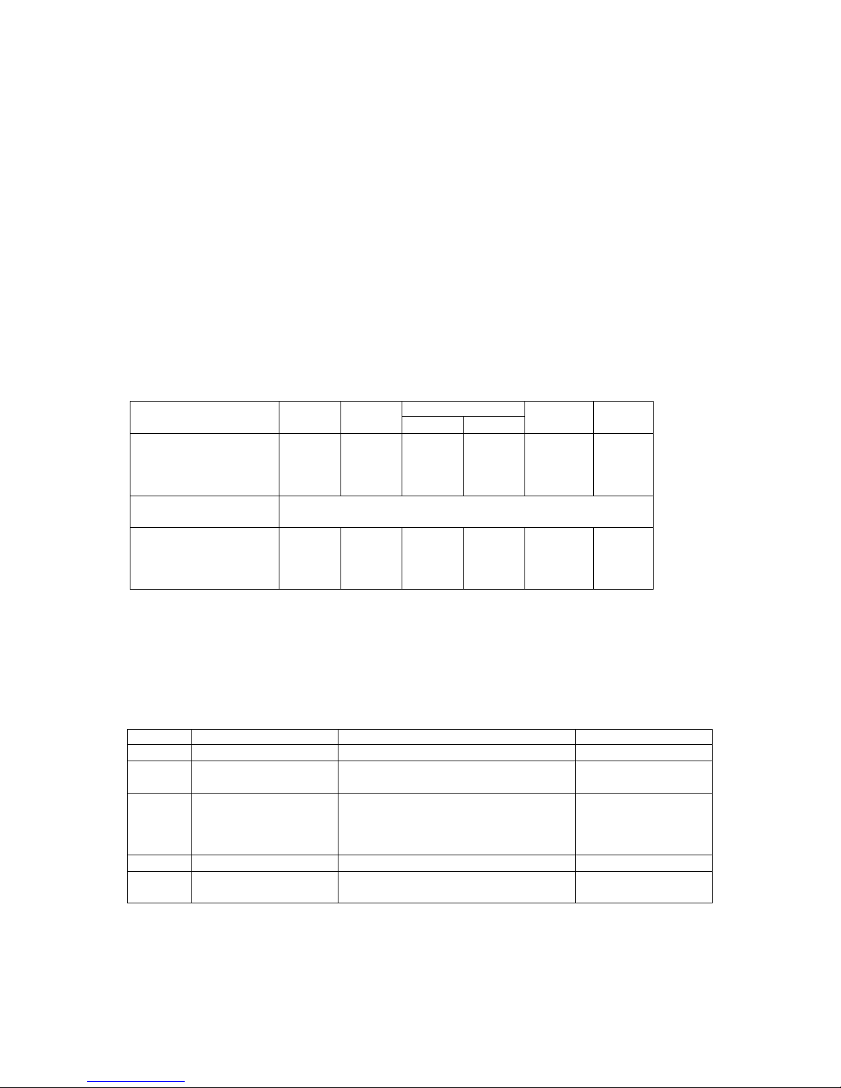
The RAID configuration in the disk array unit can be used in the combinations shown in the table
below. (G = 1000^3)
RAID type RAID1 RAID5
Number of logical drives
in configuration
Number of logical drives
per subsystem
Storage capacity per
logical drive (When 73GB disk drive is used)
1+1 4+1 6 to 120 6 to 60
71.6GB 286.4GB
RAID6 *1
S2500 S1500
1,024 max.
286.4GB
to 6TB
286.4GB
to 3TB
RAID10 RAID50
2x2, 3x2,
4x2, 5x2,
6x2, 7x2,
8x2
143.2GB
to
572.8GB
5x2, 5x4
572.8GB
to
1145.6G
B
* A combination of disk drives of the same capacity and same rotational speed is required for configuring logical
drives.
The NFx500-SE82E only supports RAID6 and does not support any other RAID configuration.
*1 Two mod es (66%-mode and 80%-mode) can be selected according to capacity efficiency.
The RAID types have the following characteristi cs.
Level Function Advantage Disadvantage
RAID1 Mirroring High reliability High cost
RAID5
RAID6
RAID10 Striping of RAID-1 High-speed data read/write High cost
RAID50 Striping of RAID- 5
Striping of data and
redundant data
Striping of data and
redundant data
High capacity efficiency
High reliability that allows continuous
operation even if two disk drives fail.
Capacity can be expanded for every
drive.
High-speed data read
High capacity efficiency
Low-speed data
writing
Low-speed data
writing
High induction cost
xxix
 Loading...