

NEC NF2300-SR412E, NF2300-SR413E, NF2300-SR422E, NF2300-SR414E User Manual
NF2300-SR412E/SR413E/SR414E/SR422E
Disk Array Unit
User's Guide
NOTE:
Read this manual carefully before using the unit. Keep this
manual nearby as a handy reference and refer to the
"CAUTION" and "WARNING" statements whenever necessary.
NEC CONFIDENTIAL AND PROPRIETARY
A
ll rights reserved by NEC Corporation. This document must be
used solely for the purpose for which it was furnished by NEC
Corporation. No part of this document may be reproduced or
disclosed to others, in any form, without the prior written
permission of NEC Corporation.
856-850305-101-A
FEDERAL COMMUNICATIONS COMMISSION
RADIO FREQUENCY INTERFERENCE STATEMENT
NOTE: This equipment has been tested and found to comply with the limits for a Class A
digital device, pursuant to Part 15 of the FCC Rules. These limits are designed to
provide reasonable protection against harmful interference when the equipment is
operated in a commercial environment. This equipment generates, uses, and can radiate
radio frequency energy and, if not installed and used in accordance with the instruction
manual, may cause harmful interference to radio communications. Operation of this
equipment in a residential area is likely to cause harmful interference in which case the
user will be required to correct the interference at his own expense.
Warning
This is a Class A product. In domestic environment this product may cause radio
interference in which case the user may be required to take adequate measures.
i
Safety Precautions
Before using this unit, read this manual carefully and keep cautions in order to use this
unit safely and correctly and to avoid to be a cause of damage to the body or properties.
Keep this manual to see whenever it is necessary.
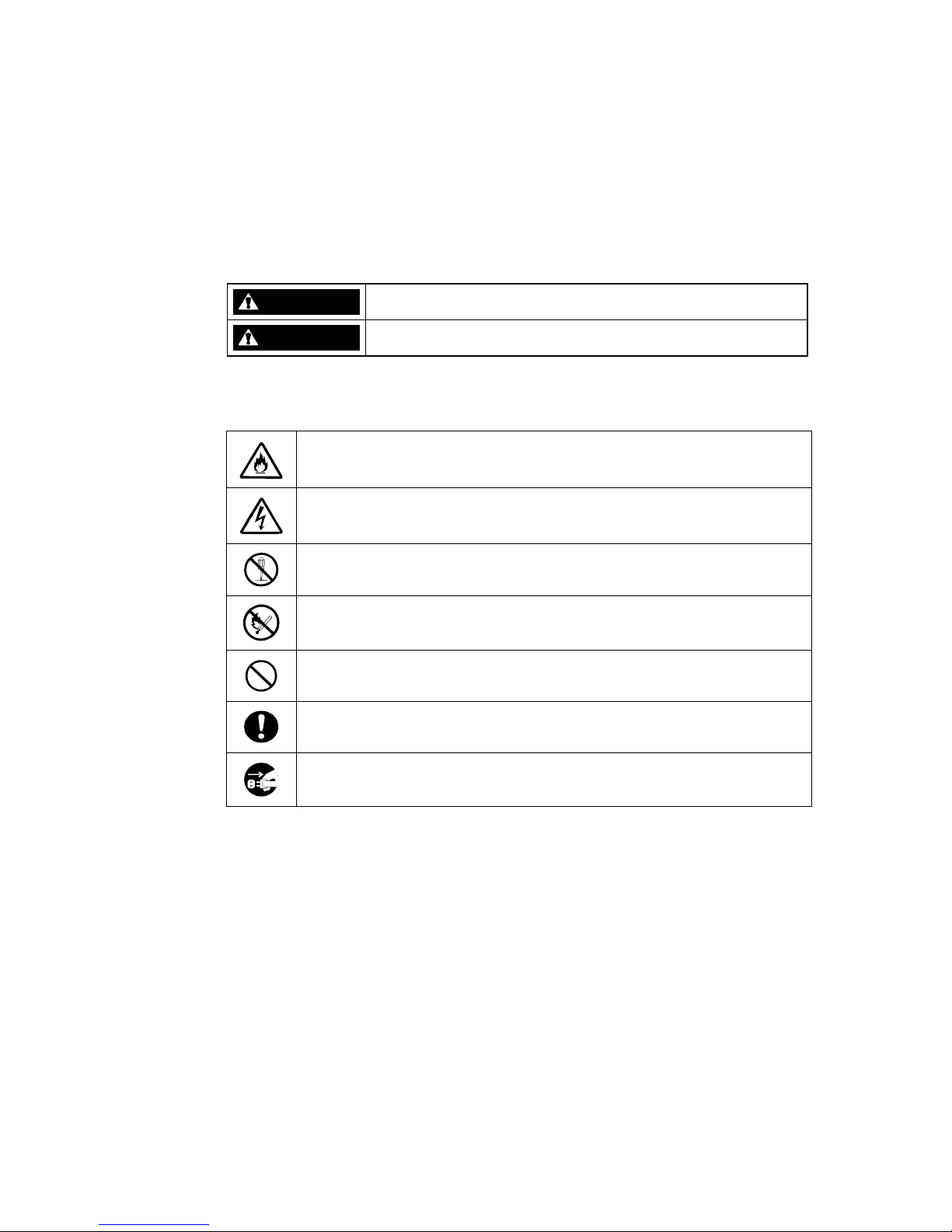
The following symbols are used in this manual so that you can easily understand how to
operate the unit safely and correctly.
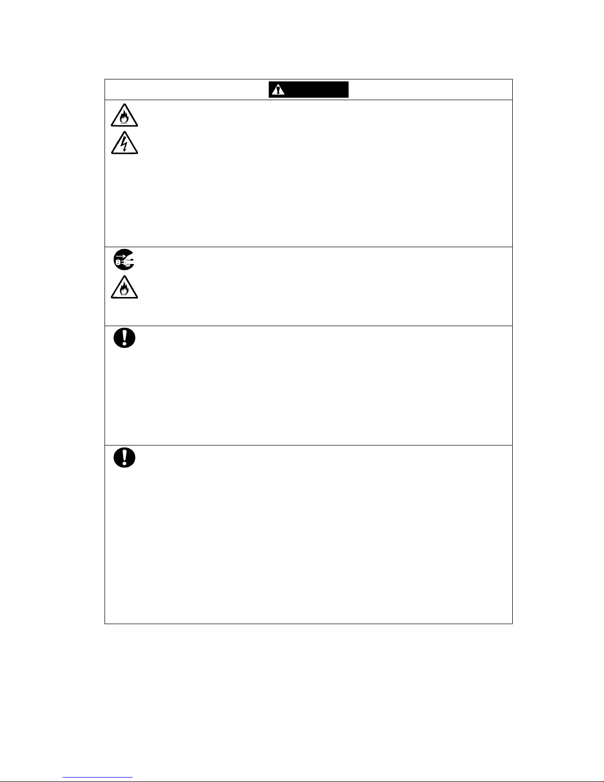
WARNING
Indicate there is a risk of death or serious wound.
CAUTION
Indicate there is a risk of burn or injury.
Risks and necessary actions to reduce risks are indicated individually by the following
symbols.
Indicates the risk of smoke emission or fire outbreak.
Indicates the risk of electric shock.
Indicates the danger of an injury due to harmful material.
Indicates instructions to keep a device away from inflammable object.
Indicates notice of general prohibition.
Indicates required general actions for operators.
Indicates instructions to pull the plug of a power cord from outlet and to off
main circuit breaker.
ii
Notes on Use
The following includes information necessary for proper and safe operation of the disk
array unit.
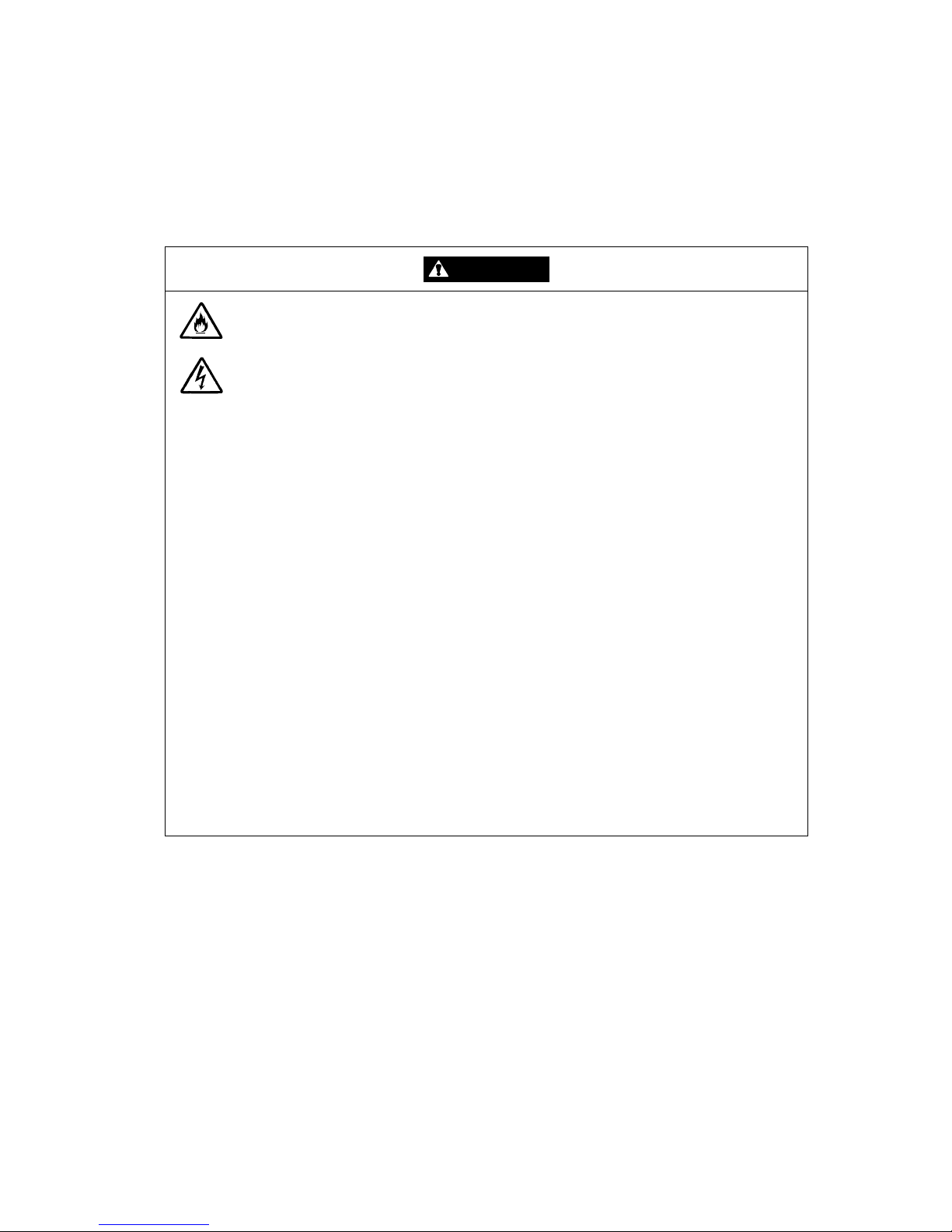
WARNING
Do not use the disk array unit in an area with much moisture or water usage. If so,
a fault, electrical shock, or fire may occur.
Do not use the disk array unit in an area where inflammable gas and/or
combustible substance are placed. If so, fire or explosion may occur.
Do not concentrate power cords only to some AC outlets. If so, fire may occur.
Do not put a heavy substance on a power cord. If so, the coating of the power
cord may be broken, fire may occur, and/or you may be electrically shocked.
Do not install the disk array unit in an area of much moisture or dust. Remove dust
adhering to AC outlets and the plugs of power cords, if any. If dust remains
adhering to an AC outlet and/or plug, fire may occur.
Do not connect the plug of a power cord to an AC outlet with a wet hand. If so, you
may be electrically shocked.
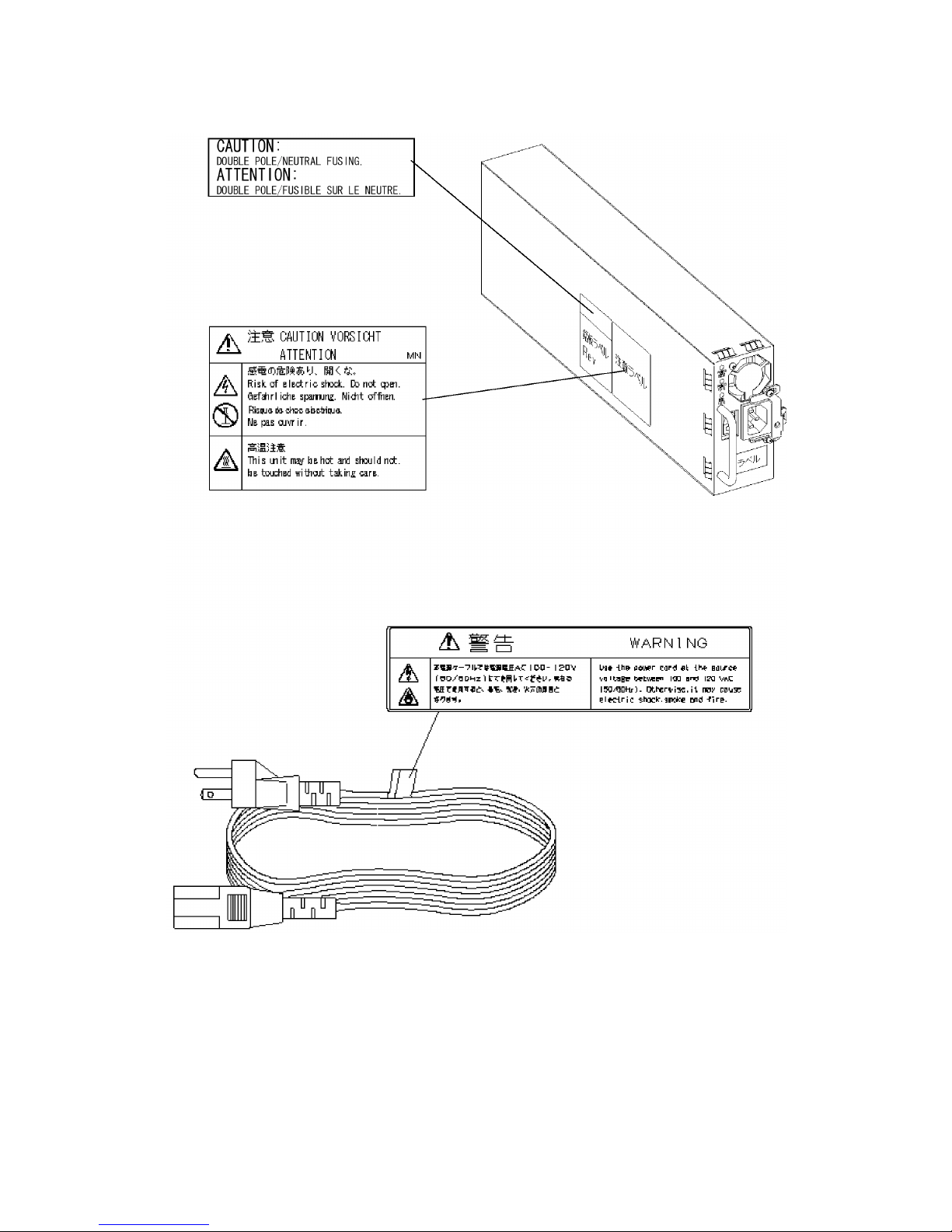
While the disk array unit can accept the power of 100 - 240 VAC (50/60 Hz), the
power cord coming with the disk array unit can only accept 100 – 120 VAC. Use
100 – 120 VAC (50/60 Hz) when the attached power cord is used. Using power of
different voltage may cause electric shock, smoke, and/or fire to occur.
The LAN card of the disk array unit contains lithium battery. Do not remove the
lithium battery. The lithium battery may explode when it is brought close to fire or
immersed in water. Dispose of the LAN card according to local ordinance. Contact
your local government for details.
If the disk array unit does not operate normally due to the life of the lithium
batteries, contact your service representative. Do not disassemble the LAN card,
or replace or charge battery by yourself.
iii
CAUTION
Do not install the disk array unit and the host systems on unstable places. If so,
some substances may be dropped to cause you to be injured.
Do not install the disk array unit and the power cords in an area with direct sunshine
or near an apparatus generating heat such as a heater. If so, a fault may occur.
Further, the coating of the power cord may be melted to cause fire or electric shock
to occur.
Insert the plug of a power cord to an AC outlet securely. Any power cord shall be
routed with sufficient margin to avoid excess force from being given to the plugs of
the power cord or the power cord itself. If a power cord is removed from the AC
outlet during operation, data may be lost and/or a fault may occur.
To prevent electric shocks, connect a power cord to an AC outlet with earth
terminal. Connection of the earth line to a gas tube is extremely dangerous. Never
do it.
Connect or remove a peripheral device from the disk array unit after turning off all
the powers of the disk array unit and peripherals and pulling out the power cords
from the AC outlets. If not, some units may be broken and/or you may be electrically
shocked.
To carry or reinstall the disk array unit, disconnect all cables and power cords
beforehand. If not, some units may be broken, you may be electrically shocked,
and/or a fire may occur.
Handle optical fibers carefully and gently.
The minimum bending radius of optical fiber shall be 30 mm.
Dust and/or dirt may attenuate the optical power of optical fiber to cause data errors
to occur. Clean any optical fiber cable whenever it is inserted into the mating
connector in the following procedure.
1. Blow parts cleaning gas (e.g. air splay) to the connector of the optical fiber cable
for several seconds.
2. Wipe the connector with non-woven cloth soaked with alcohol for several times.
3. Blow the parts cleaning gas to the connector again.
To install the unit in a rack, observe the following guidelines.
1. TMRA – If installed in a rack, consideration should be given to installing the
equipment in an environment compatible with the TMRA.
2. Reduced Air Flow – Installation in a rack should be such that the amount of air flow
required for safe operation of the equipment is not compromised.
3. Mechanical loading – Mounting of the equipment in the rack should be such that a
hazardous condition is not achieved due to uneven mechanical loading.
4. Circuit Overloading – Consideration should be given to the connection of the
equipment to the supply circuit and the effect that overloading the circuits might
have on overcurrent protection and supply wiring. Appropriate consideration of
equipment nameplate ratings should be used when addressing this concern.
5. Reliable Earthing – Reliable earthing of rack-mounted equipment should be
maintained. Particular attention should be given to supply connections other than
direct connections to the branch circuit (e.g., use of power strips).
iv
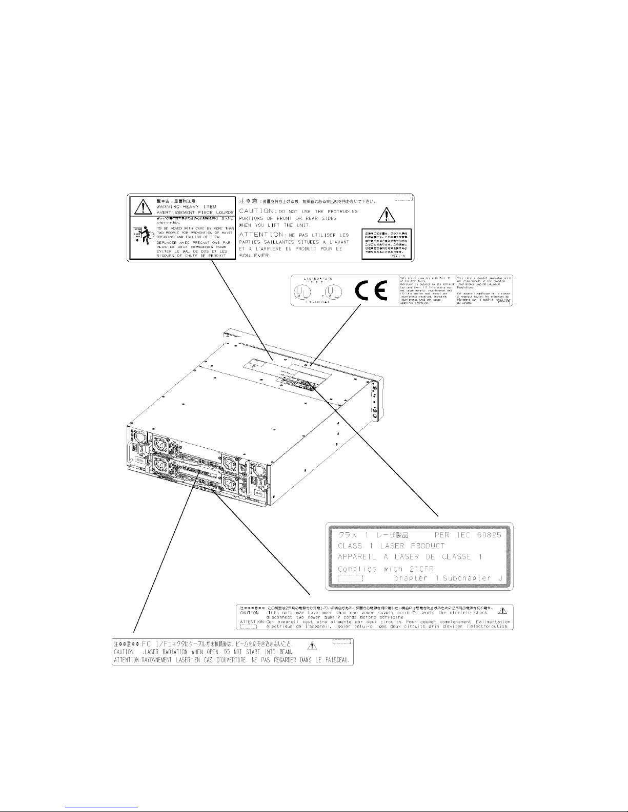
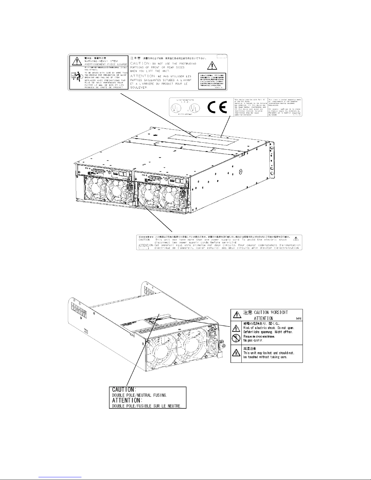
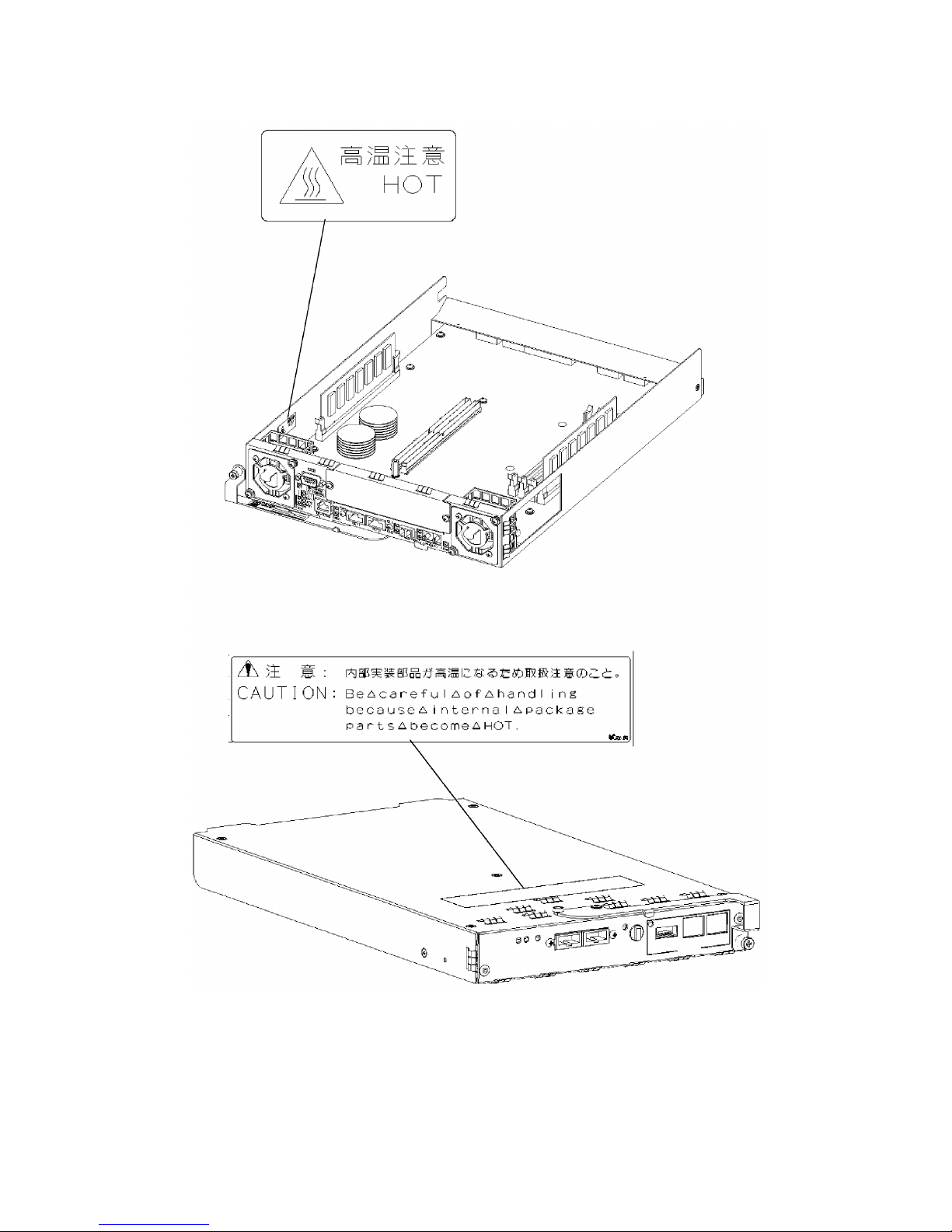
Indication on Safety
Warning labels are put on parts possibly be dangerous and/or surroundings in the disk
array unit. They are intended to always make you conscious of possible dangers when you
handle the disk array unit. (Do not peel off the labels or do not make them dirty.) If any of
the labels is not put on the proper position, is peeled off a little, or is dirty to make it
unreadable, contact your sales agent or maintenance engineer.
v
vi
vii
viii

ix
Trademarks
Microsoft, Windows, Windows NT, and Windows 2000 are registered trademarks of
Microsoft Corporation in the United States and other countries.
HP-UX is a registered trademark of Hewlett-Packard Company of the United States.
Solaris is a trademark or registered trademarks of Sun Microsystems, Inc. in the United
States and other countries.
All other product, brand, or trade names used in this publication are the trademarks or
registered trademarks of their respective trademark owners.
Momentary voltage drop prevention
This product may be affected by a momentary voltage drop caused by lightning. To
prevent a momentary voltage drop, an AC uninterruptive power supply (UPS) unit should
be used.
Notes
(1) No part of this manual may be photocopied in any form without prior written
consent from NEC.
(2) The information in this manual is subject to change without notice.
(3) All possible efforts are being made to create this manual, but in the event that any
technical or editorial errors or omissions are found, contact your dealer.
(4) Save this manual in a convenient area even after you finished reading it.
(5) When transferring this unit to other person, be sure to transfer this manual also.
(6) NEC shall not be liable for any loss or lost profits from the use of this disk array unit
regardless of the item in (3).
(7) This unit is not intended to be installed into the installation or equipment associated
with human life, such as medical equipment, atomic installation or equipment, aerial
and space equipment, transportation installation and equipment and to be installed
into and to control the installation or equipment requiring high reliability. If you use
this unit for these installation, equipment, or control system, NEC shall not be liable
for an accident leading to an injury or death, fire, or social loss resulting from a
breakdown of our product.
© 2003 NEC Corporation
No part of this manual may be photocopied or modified in any form without prior written
consent from NEC.

x
Preface
Thank you very much for your purchase of the disk array unit. This manual is intended to
enable you to correctly use the disk array unit NF2300-SR4xxE connected with the NEC
Express5800 series, NX7000 series, or CX5000 series system.
Before using the disk array unit, also read the manuals of several devices including NEC
Express5800 series, FibreChannel controller, NX7000 series, FC-AL SCSI connection
mechanism, or CX5000 series to be connected with the disk array unit and the manual of
the used OS.
NEC Storage BaseProduct needs to be purchased separately for using the disk array unit.
The following options are provided for NF2300-SR4xxE disk array unit:
To expand storage capacity:
• Additional disk enclosure NF2300-SE41E
• Additional 36-GB disk drive NF2300-SM412E
• Additional 73-GB disk drive NF2300-SM413E
• Additional 147-GB disk drive NF2300-SM414E
• Additional 36-GB/15,000 rpm disk drive NF2300-SM422E
To expand cache memory size:
• Additional cache memory NF2300-SC01E and NF2300-SC02E
To expand host port:
• Additional host FC port NF2300-SP03E
To expand disk port:
• Additional control card NF2300-SP02E
After reading the manual, store it in an area where you can access it easily.
First edition, February 2003

xi
Check of Components in Package
(1) Unpacking
Open the package and take out the disk array unit and accessories from the package
without large shock. The disk array unit is greatly heavy. Accordingly, if two people
or less lift the unit, their backs may be damaged. To take out the disk array unit from
the package, more than three people should always support the bottom of the unit
without holding the power supply on the rear face and the projections of the
controller.
The package is specially designed for carriage of a precision device. Do not dispose
of the package because it is required to return the disk array unit to the factory for its
repair.
(2) Inspection
After unpacking, check that all the components listed in the table below are
provided. If any of the components is missed, contact your sales agent. Next, inspect
the disk array unit and accessories. If any of the components is damaged, contact
your sales agent.
No. Product name Remarks Qty
1 NEC Storage S2300 1/2 1
2 NEC Storage S2300 2/2 1
NF2300-SR412E: 36 GB 3
NF2300-SR413E: 73 GB 3
NF2300-SR414E: 147 GB 3
3 Disk drive
(Installed in NEC Storage S2300
2/2)
NF2300-SR422E: 36 GB/15K 3
4 Power cord Length 5 m (for 100-120 VAC) 4
5 HSSDC cable Length 1 m 2
6 DE diagnosis cable Length 1 m 2
For NEC Storage S2300 1/2 1 7 Front mask
For NEC Storage S2300 2/2 1
8 Key 2
9 User's Guide (this document) 1
10 Packing list 1
11 Location label 1
12 T&D program DAT cartridge for NX7000 system 1
13 Rack mount kit For NEC Storage rack (L and R) 2
* Use the FC cable (HSSDC) and DE diagnosis cable provided with the additional
disk enclosure or separately priced DE cable (NF9120-SJ04E) for connecting disk
array unit NEC Storage S2300 with the additional disk enclosure.
xii
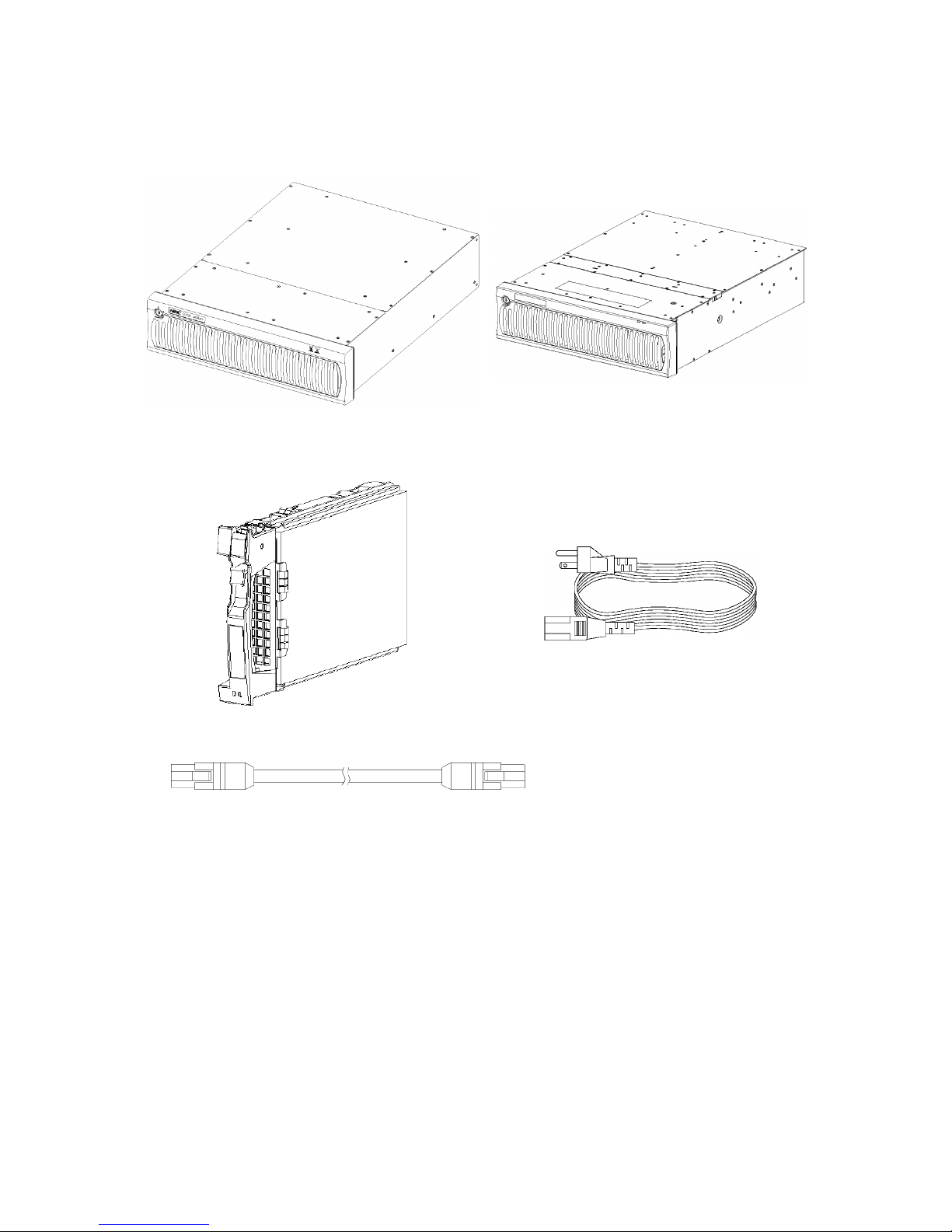
NF2300-SR4xxE
(1) NEC Storage S2300 (1/2) (The figure above
shows the unit with the front mask installed.)
(2) NEC Storage S2300 (2/2) (The figure
above shows the unit with the front mask
installed.)
(3) Disk drive (4) Power cord
(5) HSSDC cable (6) DE diagnosis cable
(7) Front mask (8) Key
(9) User's Guide (10) Packing list
(11) Location label (12) T&D program
(13) Rack-mount kit
xiii
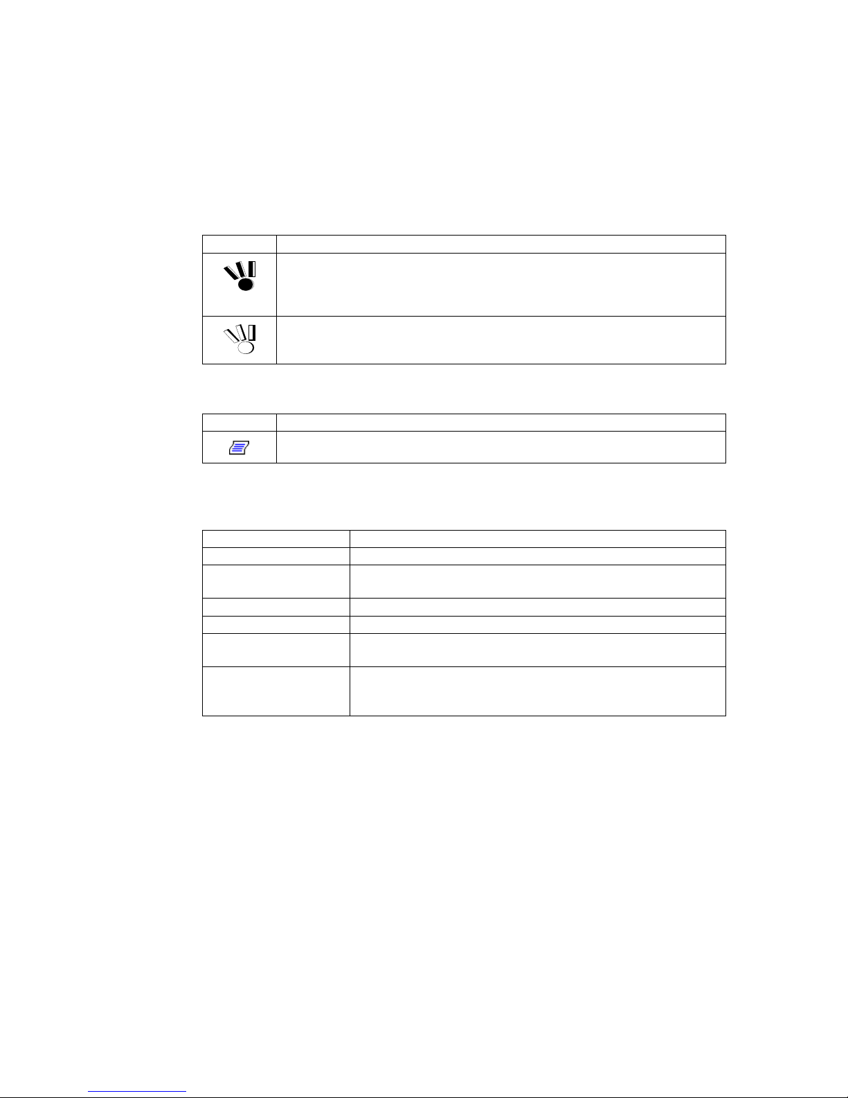
Legend
Symbols in the Text
This User's Guide uses the following symbols to indicate improper handling which may
cause the disk array unit to be defected or frozen.
Symbol Description
If the description is ignored to handle the disk array unit incorrectly, the unit may
be defected, some software used in the unit may be broken, and/or the data created
by the user may be broken.
If the description is ignored to handle the disk array unit incorrectly, the unit may
be defected and/or some software used in the unit may not operate normally.
This User's Guide also uses the following symbol.
Symbol Description
Supplement of the text
This User's Guide uses the following terms to indicate specific devices.
Disk array unit Indicates NF2300-SR4xxE.
Array controller Indicates the NEC Storage S2300 1/2.
Disk enclosure Indicates the NEC Storage S2300 2/2 and additional disk enclosure
(sold separately).
Disk drive Indicates the hard disk with dedicated tray.
Dummy tray Indicates the dedicated tray only, with no hard disk installed.
Host system Indicates the NEC Express5800 series, NX 7000 series, or CX5000
series.
Host bus adapter Indicates the FibreChannel controller for NEC Express5800 series,
FC-AL SCSI connection mechanism for NX7000 series, or
FibreChannel controller for CX5000 series.

xiv
Contents
Safety Precautions..............................................................................................i
Notes on Use..................................................................................................... ii
Indication on Safety........................................................................................... iv
NF2300-SR4xxE.............................................................................................. xii
1. NOTES ON INSTALLATION AND HANDLING OF DISK ARRAY UNIT........1
1.1 Note on Carrying Disk Array Unit.........................................................1
1.2 Environment in Use of Disk Array Unit.................................................2
1.3 Installation and Connection of Disk Array Unit .....................................3
1.4 Notes on Use of Disk Array Unit ..........................................................5
1.5 Routine Inspection of Disk Array Unit ..................................................6
1.6 Notes on Storage or Carriage of Disk Array Unit..................................7
2. FEATURES OF DISK ARRAY UNIT.............................................................8
2.1 Hot Spare Feature...............................................................................9
2.2 Write Cache Feature .........................................................................11
2.3 Dynamic Cross Call Feature..............................................................12
2.4 Management Software.......................................................................12
2.5 RAID Configuration............................................................................13
3. NAMES AND ROLES OF SECTIONS ........................................................14
3.1 Array Controller (Front)......................................................................14
3.2 Array Controller (Rear) ......................................................................16
3.3 Battery Backup Unit...........................................................................17
3.4 Power Supply for Array Controller .....................................................18
3.5 Controller...........................................................................................20
3.6 LAN Card...........................................................................................23
3.7 Disk Enclosure (Front).......................................................................25
3.8 Disk Enclosure (Rear)........................................................................27
3.9 Power Supply for Disk Enclosure.......................................................28
3.10 Adapter..............................................................................................30
3.11 Additional Control Card......................................................................32
3.12 Additional FC Port .............................................................................34
4. INSTALLATION AND CONNECTION PROCEDURES ...............................35
4.1 Installation and Connection Procedures ............................................35
5. CONNECTION OF DISK ARRAY UNIT......................................................36
5.1 Notes on Connection of Disk Array Unit.............................................37
5.2 Connection of Disk Array Unit............................................................38
5.3 Connection of Disk Array Unit as Additional Unit ...............................48
5.4 Connection of Ethernet Cable............................................................52
5.5 Connection of Power Cords...............................................................53

xv
6. ADDITION OF OPTIONAL DEVICES .........................................................56
6.1 Addition of Disk Drive ........................................................................56
6.2 Addition of Disk Enclosure.................................................................61
6.3 Addition of Additional Control Card....................................................67
6.4 Addition of Additional Host FC Port ...................................................73
6.5 Addition of Cache Memory ................................................................74
7. HANDLING OF DISK ARRAY UNIT.............................................................79
7.1 Notes on Handling of Disk Array Unit.................................................79
7.2 Power On/Off of Disk Array Unit ........................................................80
7.3 LD (Logical Disk) Setting Procedure..................................................84
7.4 Spare Disk Setting Procedure............................................................84
8. ACTION TAKEN AT OCCURRENCE OF FAULT OR ERROR ...................85
8.1 Countermeasures Taken When Occurrence of a Fault is Suspected.86
8.2 Computer Virus .................................................................................87
8.3 Indication at Occurrence of Fault .......................................................88
8.4 Fault of Controller..............................................................................89
8.5 Fault of Controller Cooling Fan..........................................................92
8.6 Fault of LAN Card..............................................................................93
8.7 Fault of Power Supply for Array Controller.........................................94
8.8 Fault of Battery Backup Unit..............................................................97
8.9 Fault of Disk Drive.............................................................................99
8.10 Fault of Power Supply for Disk Enclosure........................................102
8.11 Fault of Adapter...............................................................................106
8.12 Check of Type Name and Manufacturing Numbers .........................109
8.13 Preparation before Phone Call.........................................................111
8.14 Service and Support ........................................................................111
8.15 Unit Life/Repair Service Period........................................................111
8.16 Disposal of Disk Array Unit ..............................................................111
9. PRODUCT SPECIFICATION....................................................................112
9.1 Basic Specification of Disk Array Unit ..............................................112
9.2 Optional Components......................................................................112
9.3 Environmental Conditions of Disk Array Unit ...................................113
9.4 Power Specification.........................................................................113
9.5 External Dimension and Weight of Disk Array Unit ..........................113
9.6 Life Expectancies of Components ...................................................113
9.7 How to Change Topology and Data Transfer Rate ..........................114

xvi
Appendix A Features of Disk Array Unit .........................................................116
1. Battery Backup................................................................................116
2. Cross Call Feature...........................................................................116
2.1 Initial Assignment Feature...........................................................116
2.2 Auto Assignment Feature............................................................117
2.3 Cross Call Feature ......................................................................117
3. Expand LUN Feature.......................................................................118
4. Auto Repair Mode............................................................................118
5. Hot Spare Mode ..............................................................................119
6. 1-BBU Cache Enable Mode.............................................................119
7. 1-Controller Cache Enable Mode.....................................................119
8. Repair Time.....................................................................................120
9. Dummy Logical Disk........................................................................120
10. Dynamic Capacity Expansion ..........................................................120
11. Logical Disk Capacity ......................................................................128
11.1 Arbitrary Logical Disk Capacity ...................................................128
11.2 Maximum Logical Disk Capacity..................................................128
12. Access Control ................................................................................130
12.1 Port Mode ...................................................................................130
12.2 WWn Mode.................................................................................130
13. Dynamic Data Replication ...............................................................131
14. Miscellaneous Settings....................................................................131
15. Various Default Values ....................................................................131
16. Notes on Use of NEC Storage DynamicDataReplication .................132
17. Disk Enclosure Movement...............................................................133
18. Setting of OS Type ..........................................................................133
19. Program Products............................................................................134
20. Updating of Control Software...........................................................134
Appendix B Installation Procedure .................................................................135
1. Creation of Logical Disks.................................................................135
1.1 Unbinding Logical Disk Already Bound .......................................135
1.2 Binding Logical Disk....................................................................136
1.3 Turning on Cross Call Feature ....................................................137
1
1. NOTES ON INSTALLATION AND HANDLING OF DISK
ARRAY UNIT
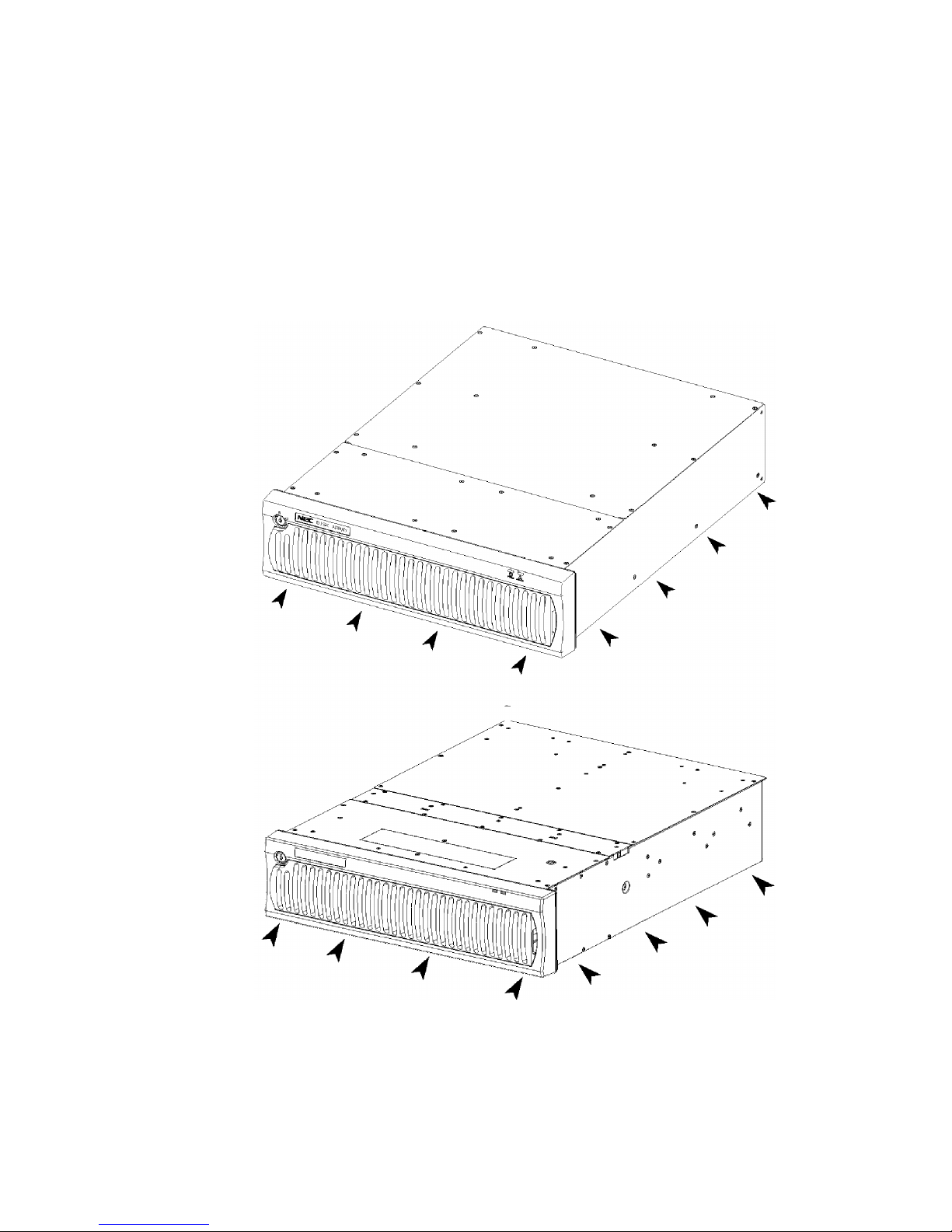
1.1 Note on Carrying Disk Array Unit
Be sure to hold the bottom the disk array unit when carrying it.
Hold the front or side bottom of the disk array unit if possible.
2
1.2 Environment in Use of Disk Array Unit
In installation of the disk array unit, take into account the following items on the location,
room temperature, space required for handling, ventilation, and other conditions.
Install the disk array unit indoors.
Do not expose the disk array unit to direct sunlight. Use a window shade or
curtain to block sunlight to the unit if necessary.
Install the disk array unit on a level floor with sufficient strength. In addition, do
not give shocks and/or vibrations to the disk array unit. If so, some components
may be dropped to cause the disk array unit to be defected and/or people to be
injured.
Install the disk array unit in an area under the following conditions; temperature
range between 5°C - 40°C and humidity range between 10% - 80% (without
condensation).
Do not install the disk array unit in an area with water or oil poured, area
suffering liquid such as water and oil, suffering steam, area with steam, and
area with much moisture. If so, a fault or electrical shock may occur.
Do not install the disk array unit in an area with emission of chemical steam or
an area where the disk array unit may be contact with inflammable substance.
If so, a fault, fire, or explosion may occur.
Do not install the disk array unit in an area with much dust. If so, a fault may
occur.
Do not install the disk array unit in an area with direct sunshine or near fire or
an apparatus generating heat such as stove. If so, a fault or deformation may
occur.
Do not install the disk array unit near TV, radio, and codeless telephone. Some
noise may appear in the TV, radio, and codeless telephone.
Do not use cellular phones near the disk array unit. If so, a fault may occur.
Do not install the disk array unit near a device generating strong magnetism. If
so, a fault may occur.
Install the disk array unit so that the ventilating holes opened on the front and
rear faces are not blocked. If not, heat generation and/or fault may occur.
3
1.3 Installation and Connection of Disk Array Unit
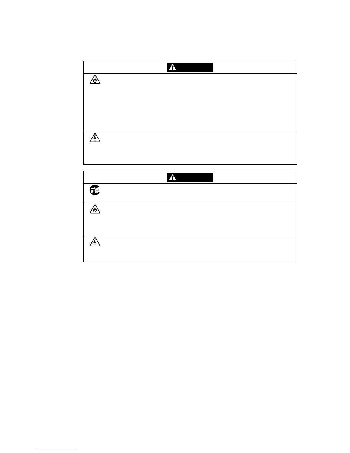
WARNING
Do not use the disk array unit in an area with much moisture or water
usage. If so, a fault, electrical shock, or fire may occur.
Do not use the disk array unit in an area where inflammable gas and/or
combustible substance are placed. If so, fire or explosion may occur.
Do not install the disk array unit in an area of much moisture or dust.
Remove dust adhering to AC outlets and the plugs of power cords, if any.
If dust remains adhering to an AC outlet and/or plug, fire may occur.
Do not concentrate power cords only to some AC outlets. If so, fire may
occur.
Do not put a heavy substance on a power cord. If so, the coating of the
power cord may be broken, fire may occur, and/or you may be electrically
shocked.
Do not connect the plug of a power cord to an AC outlet with a wet hand. If
so, you may be electrically shocked.
CAUTION
Make sure to disconnect all power cords and FC cables before relocating
the disk array unit. If not, a malfunction of the system, an electric shock
and/or fire may occur.
While the disk array unit can accept the power of 100 - 240 VAC (50/60
Hz), the power cord coming with the disk array unit can only accept 100 –
120 VAC. Use 100 – 120 VAC (50/60 Hz) when the attached power cord
is used. Using power of different voltage may cause electric shock,
smoke, and/or fire to occur.
Do not install the disk array unit and the power cords in an area with direct
sunshine or near an apparatus generating heat such as a heater. If so, a
fault may occur. Further, the coating of the power cord may be melted to
cause fire or electric shock to occur.
4
The array controller and the disk enclosure weigh 34 kg or more. Hold the
array controller and disk enclosure firmly with at least three people to carry
it. Carrying the devices only by two or less people may strain their back.
Select the place where the disk array unit can be connected to the AC
outlet by using the attached power cord or the power cord approved by
NEC.
Insert the plug of a power cord into an AC outlet securely. If some
clearance remains between the plug of the power cord and the AC outlet,
dust may enter into the clearance. This then may cause fire to occur.
Provide sufficient margins for the cables connected to the disk array unit
so that legs may not be trapped by the cables. Avoid power plugs and FC
connectors from suffering excess forces.
Do not use cables connected to the disk array unit with them leaving bent.
If so, a fault or fire may occur.
Use the cables approved by NEC as those connected to the disk array
unit and check the destinations to which the cables are connected. In
addition, always lock power cords and FC cables when they are
connected.
Use the power source independent from TV or radio. Otherwise, a noise
may be generated.
To connect a cable to the mating connector, make sure that the connector
of the cable is not damaged and any pins are not bent. Using a cable not
approved by NEC or a damaged cable may cause fire to occur.
To disconnect a cable from the mating connector, always hold the
connector of the cable. Do not hold the cable itself to disconnect it.
5
1.4 Notes on Use of Disk Array Unit
Do not let any animal (pet) or children touch the cable connected to the
disk array unit. Pulling the cable may cause the unit to fall down, resulting
in failure of the unit.
Do not enter any liquid such as water into the disk array unit. If so, you
may be electrically shocked or the unit may be defected. If some liquid is
entered into the disk array unit, turn off the power and contact your sales
agent or maintenance engineer. If the disk array unit seems dry, only a
small amount of liquid may remain to cause the unit to be defected.
Do not enter foreign substances such as clip and screw into the disk array
unit through the ventilating holes on the front or rear face. If so, a fault
may occur.
Do not disassemble or modify the disk array unit. If so, a fault or electrical
shock may occur. Repair of the unit will be charged regardless of
warranty.
If the disk array unit will not be used for a long period, disconnect the
plugs of the power cords from the AC outlets for safety.
Disconnect the power plug from the outlet when a thunderstorm is
approaching. If it starts thundering before you disconnect the power
plug, do not touch any part of the unit including the cables. If any failure is
found later, contact your sales agent.
6
1.5 Routine Inspection of Disk Array Unit
CAUTION
To clean the disk array unit, always turn off the power and also disconnect
the plugs of power cord from AC outlets. If not, you may be electrically
shocked.
If a surface of the disk array unit becomes dirt, wipe the surface lightly with
soft cloth. Wiping the surface by using chemicals such as benzene and
thinner, or volatile chemicals, may cause the surface to be deformed or
discolored. In addition, note that splaying insecticide on a surface may
cause the surface to be deformed or discolored.
It is recommended to clean the inside of the disk array unit periodically. It
is because dust may be accumulated after the disk array unit is used for a
long time.
Contact your sales agent or maintenance engineer for the cleaning of the
inside of the disk array unit.
Users must not disassemble and/or repair the disk array unit because it is
dangerous.
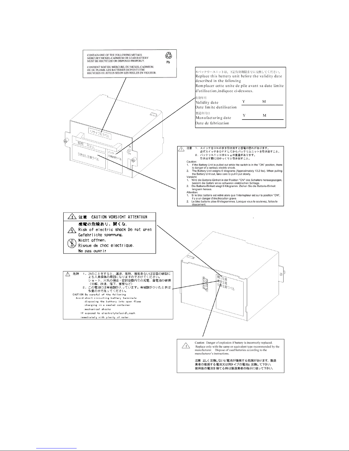
Do not use any battery backup unit exceeding its life. If so, a fault or fire
may occur. (Assumed life of battery backup unit: 2.5 years in operating
environment at temperature of 27°C)
7
1.6 Notes on Storage or Carriage of Disk Array Unit
Do not store the disk array unit in an area where the temperature may
increase extremely or the difference between the warm and cold states is
considerably large. In addition, do not store the disk array unit in an area
with much moisture or dust.
Note that foreign substances such as water and metals may not be
entered into the disk array unit during storage. Using the disk array unit
with some foreign substance left inside may cause a fault, electrical shock,
or fire to occur.
During the storage, do not put any substance on the disk array unit or do
not place the disk array unit on an area where the unit may be dropped.
To use the disk array unit after storage for longer than six months, it is
recommended to contact your sales agent or maintenance engineer for
inspection and/or repair.
The array controller and the disk enclosure weigh 34 kg or more. Hold the
array controller and disk enclosure firmly with at least three people to carry
it. Carrying the devices only by two or less people may strain their back.
Do not hold the protrusions from the power supply or controller. Doing so
applies excessive force to the power supply and controller. As a result,
the power supply or controller may be damaged, and/or the array
controller or disk enclosure may fall and cause personal injury.
Make sure to package the disk array unit when transporting it with the
packing material that comes with the disk array unit. If any other packing
materials are used, a vibration or shock generated during transportation
may cause a malfunction of the unit.
8
2. FEATURES OF DISK ARRAY UNIT
The disk array unit has the following features.
NF2300-SR4xxE is a high-performance disk array unit designed for NEC Express5800,
NX7000, and CX5000 systems. NF2300-SR412E, NF2300-SR413E, NF2300-SR414E
and NF23200-SR422E are equipped with three 36GB, 73GB, 147GB and 36GB/15,000
rpm disk drives, respectively.
* Ask your sales agent for non-NEC servers (hosts) which are supported and
compatible operating systems.
You can easily expand the storage capacity by installing additional disk drives (options) in
expansion slots (at shipment: 12 slots) of the disk array unit.
An additional disk enclosure (option) to enable the expansion of the storage capacity of
the disk array unit is provided for the disk array unit.
NF2300-SR4xxE supports RAID levels 0, 1, 5, and 10. If a fault occurs in a single disk
drive, NF2300-SR4xxE can continue the operation without loss of data (except RAID
level 0).
Any defected disk drive can be replaced with a new one without system shutdown.
Further, the disk array unit has the auto repair feature which automatically starts data
recovery after the replacement of the defected disk drive.
If a single disk drive is specified as the spare disk, the data in the defected disk drive can
be immediately recovered in the spare disk. The use of this hot spare feature as well as the
auto repair feature allows the data in the defected disk drive to be automatically recovered
in the spare disk as soon as a disk drive is defected. This improves the system reliability.
The disk array unit has the cache memory data hold function by using cache memory,
power supply, and battery backup unit. The function allows comfortable high-speed data
processing to be done under high reliability.
Further, owing to the redundant configuration of the controller, fan, power supply, and
battery backup unit as well as disk drive, the entire system is not shut down if any part of
the system is defected during operation.
See Section 9.2 "Optional Components" for the product names and part numbers of
options.
Above features of the disk array unit are effective only for the hardware failure
(e.g., the hard disk is physically damaged or inoperative). The software failure
(e.g., the data is lost or rewritten due to program excursion) is not covered by
these features. When the software failure would occur, the system could
seriously be damaged. To minimize the damage, be sure to back up the data
periodically.
9
2.1 Hot Spare Feature
Spare disks can be installed in the disk array unit. If a disk drive in the same FC loop as
the spare disk, the data in the defective disk drive is recovered in the spare disk. After the
data recovery, the disk array drive operates normally if another disk drive is defected
(except for RAID level 0). A defective disk drive can be replaced without turning off the
power of the disk array unit.
With the setting at the shipment, if the disk drive defected during the operation by using
the spare disk is replaced with a normal disk drive, the data is immediately repaired from
the spare disk to the normal disk drive.
Example of hot spare operation
DRV14
Spare disk
DRV14
DRV14
Spare disk
DRV13 DRV13 DRV13
DRV12 DRV12 DRV12
DRV11 DRV11 DRV11
DRV10 DRV10 DRV10
DRV9 DRV9 DRV9
DRV8 → DRV8 → DRV8
DRV7 DRV7 DRV7
DRV6 DRV6 DRV6
DRV5 DRV5 DRV5
DRV4
DRV4
DRV4
DRV3
DRV3
DRV3
DRV2
LDN0 RAID5
DRV2
LDN0 RAID5
DRV2
LDN0 RAID5
DRV1
DRV1
DRV1
DRV0
DRV0
DRV0
Failure in DRV1 Recovery of data
in spare disk
Replacement of DRV 1
Restore the data from spare
disk to DRV 1
* DRV: Disk drive
LDN: Logical Disk Number
The setting of the spare disk is invalid in RAID level 0. Use the spare disk in
RAID level 1, 5, or 10.
Do not move any of the factory-installed disk drives into another slot.

10
When you change a failing disk to a spare disk, confirm the following to get
the spare disk to function normally:
The capacity of the spare disk is equal to or greater than that of the failing
disk.
The rotational speed of the spare disk is equal to or faster than that of the
failing disk.
Therefore, if a large-capacity disk is defined as a spare disk, it can cover all
the disks of a high-speed drive. However, if your disk array unit contains disks
of different capacities or different rotational speeds, you should define a spare
disk matching the capacity and rotational speed of each disk in order to clarify
disk management.
Up to 2 spare disks can be installed for each disk enclosure. Up to 16 spare
disks can be installed for the entire disk array unit.
11
2.2 Write Cache Feature
For RAID level 5, the performance of the disk array unit may be decreased during writing
of a small amount of data. It is because the previous data and parity data must be read to
recalculate the parity.
The disk array unit is equipped with cache memory. When write data is stored in the cache
memory, the disk array unit terminates the command processing and then writes the data
to disk drive for improving the performance.
The cache memory is subject to battery backup by the battery backup unit.
However, for higher safety of data protection, it is recommended to use UPS
(uninterruptive power supply).
In general, if the power is shut down before the data saved in the cache memory is written
to disk drive, the data in the cache memory will be lost. To prevent this, the disk array unit
provides the battery backup by power supply and battery backup unit to retain data in the
cache memory.
The backup time is restricted as follows:
• Four days in full charge status of both the two batteries in the installation of cache
memory of the maximum capacity
The following conditions are imposed to make the write cache feature effective:
• Two controllers, one or more battery backup units, and power supplies for the battery
backup unit (PS0 for BBU0, PS1 for BBU1) are installed to operate normally.
• The battery backup units are fully charged.
If any of the conditions is not satisfied, the write cache feature does not work sufficiently.
The batteries installed in the battery backup unit are fully charged for about eight hours.
If the battery switch on battery backup unit is not turned on, the battery backup unit does
not operate.
12
2.3 Dynamic Cross Call Feature
The disk array unit is equipped with two array controllers to enable dynamic cross call
control. In the configuration, the two array controllers can access to all logical disks by
turning on cross call feature (factory-set is off). If either of the array controllers is
defected, the disk array unit can continue the operation by using the remaining array
controller. Setting can be changed by using management software.
In order to use this feature, middleware is required as well as OS.
2.4 Management Software
To view the resources of the disk array unit through the host computer in real time, use the
disk array unit management software "NEC Storage Manager" of "NEC Storage
BaseProduct Ver 2.1 - NEC Storage S2300" (separately priced) that is used with the disk
array unit. NEC Storage Manager also enables you to set the following parameters
through the host computer:
• Setting of RAID configuration (RAID0, 1, 5, 10, and hot spare disk)
• Resetting of RAID configuration
• Setting of various features such as cross-call mode
• Collection of error log
To use the disk array unit, you need to purchase "NEC Storage BaseProduct
- NEC Storage Ver2.1 2300" sold separately.
Before the disk array unit can be used, the license lock must be released by
using the license code provided with NEC Storage BaseProduct.
Be sure to release the license lock. A disk array unit without the license lock
being released cannot receive any maintenance services because the
operation cannot be guaranteed.
 Loading...