

Page 1
PART OF STOCK # 151969
®
Maintenance Manu al
ND-70926 (E)
ISSUE 1
JANUARY, 2000
NEC America, Inc.
Page 2

LIABILITY DISCLAIMER
NEC America, Inc. reserves the right to change the specifications,
functions, or features, at any time, without notice.
NEC America, Inc. has prepared this document for use by its
employees and custome rs. The information contained herein is
the property of NEC America, Inc. and shall not be reproduced
without prior written approval from NEC America, Inc.
NEAX and D
term
are registered trademar ks of NEC Corporation.
MATWorX is a trademark of NEC Corporation.
Copyright 2000
NEC America, Inc.
Printed in U.S.A.
Page 3
PAGE No.
i 1
ii 1
iii 1
iv
1 1
2 1
3 1
4
5 1
6 1
7 1
8
9 1
10 1
11 1
12
13 1
14 1
15 1
16
17 1
18 1
19 1
20
21 1
22 1
23 1
24
25 1
26 1
27 1
28
29 1
30 1
31 1
32
33 1
34 1
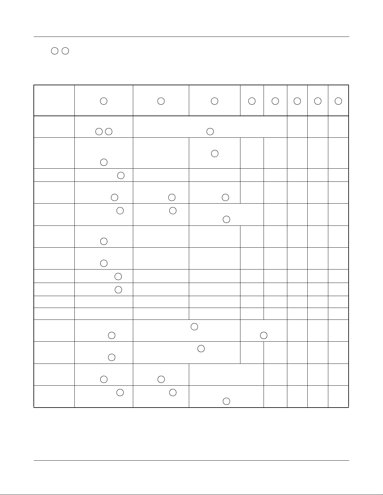
DATE JANUARY, 2000 DATE DATE DATE
DA TE DATE DATE DATE
NEAX2000 IVS
12345678
1
1
1
1
1
1
1
1
1
ISSUE 1 ISSUE 2 ISSUE 3 ISSUE 4
ISSUE 5 ISSUE 6 ISSUE 7 ISSUE 8
2
ISSUE No.
PAGE No.
35 1
36
37 1
38 1
39 1
40
41 1
42 1
43 1
44
45 1
46 1
47 1
48
49 1
50 1
51 1
52
53 1
54 1
55 1
56
57 1
58 1
59 1
60
61 1
62 1
63 1
64
65 1
66 1
67 1
68
69 1
70 1
71 1
72
12345678
1
1
1
1
1
1
1
1
1
1
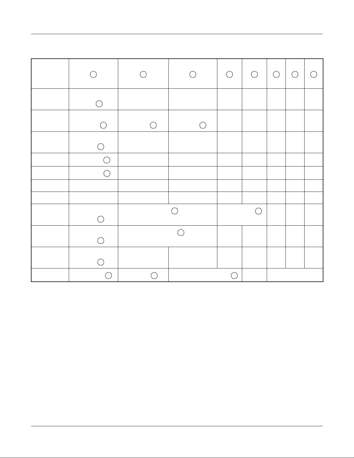
Maintenance Manual
ISSUE No.
Revision Sheet 1/2
ND-70926 (E)
Page 4
PAGE No.
73 1
74 1
75 1
76
77 1
78 1
79 1
80
81 1
82 1
83 1
84
85 1
86 1
87 1
88
89 1
90 1
91 1
92
93 1
94 1
95 1
96
97 1
98 1
99 1
100
101 1
102 1
103 1
104
105 1
106 1
107 1
108
109 1
110 1
DATE JANUARY, 2000 DATE DATE DATE
DA TE DATE DATE DATE
NEAX2000 IVS
12345678
1
1
1
1
1
1
1
1
1
ISSUE 1 I SSUE 2 ISSUE 3 ISSUE 4
ISSUE 5 I SSUE 6 ISSUE 7 ISSUE 8
2
ISSUE No.
PAGE No.
111 1
112
113 1
114 1
115 1
116
117 1
118 1
119 1
120
121 1
122 1
123 1
124
12345678
1
1
1
1
Maintenance Manual
ISSUE No.
Revision Sheet 2/2
ND-70926 (E)
Page 5

NEAX2000 IVS
2
Maintenance Manual
TABLE OF CONTENTS
Page
LIST OF FIGURES . . . . . . . . . . . . . . . . . . . . . . . . . . . . . . . . . . . . . . . . . . . . . . . . . . . . . . . . iii
LIST OF TABLES . . . . . . . . . . . . . . . . . . . . . . . . . . . . . . . . . . . . . . . . . . . . . . . . . . . . . . . . . iv
INTRODUCTION . . . . . . . . . . . . . . . . . . . . . . . . . . . . . . . . . . . . . . . . . . . . . . . . . . . . . . . . . 1
PURPOSE . . . . . . . . . . . . . . . . . . . . . . . . . . . . . . . . . . . . . . . . . . . . . . . . . . . . . . . . . . . . . . . . . . 1
USING THIS MANUAL. . . . . . . . . . . . . . . . . . . . . . . . . . . . . . . . . . . . . . . . . . . . . . . . . . . . . . . . . 1
REFERENCE MANUALS. . . . . . . . . . . . . . . . . . . . . . . . . . . . . . . . . . . . . . . . . . . . . . . . . . . . . . . 2
CHAPTER 1 MAINTENANCE SERVICE FEATURES . . . . . . . . . . . . . . . . . . . . . . . . . . . 3
HOW TO READ THIS CHAPTER. . . . . . . . . . . . . . . . . . . . . . . . . . . . . . . . . . . . . . . . . . . . . . . . . 4
FAULT MESSAGES. . . . . . . . . . . . . . . . . . . . . . . . . . . . . . . . . . . . . . . . . . . . . . . . . . . . . . . . . . . 5
General Description . . . . . . . . . . . . . . . . . . . . . . . . . . . . . . . . . . . . . . . . . . . . . . . . . . . . . . . . 5
Service Conditions . . . . . . . . . . . . . . . . . . . . . . . . . . . . . . . . . . . . . . . . . . . . . . . . . . . . . . . . . 6
Programming Procedure . . . . . . . . . . . . . . . . . . . . . . . . . . . . . . . . . . . . . . . . . . . . . . . . . . . . 7
Operating Procedure . . . . . . . . . . . . . . . . . . . . . . . . . . . . . . . . . . . . . . . . . . . . . . . . . . . . . . . 11
STATION LINE STATUS DISPLAY . . . . . . . . . . . . . . . . . . . . . . . . . . . . . . . . . . . . . . . . . . . . . . . 32
General Description . . . . . . . . . . . . . . . . . . . . . . . . . . . . . . . . . . . . . . . . . . . . . . . . . . . . . . . . 32
Service Conditions . . . . . . . . . . . . . . . . . . . . . . . . . . . . . . . . . . . . . . . . . . . . . . . . . . . . . . . . . 32
Programming Procedure . . . . . . . . . . . . . . . . . . . . . . . . . . . . . . . . . . . . . . . . . . . . . . . . . . . . 32
Operating Procedure . . . . . . . . . . . . . . . . . . . . . . . . . . . . . . . . . . . . . . . . . . . . . . . . . . . . . . . 32
BATTERY RELEASE CONTROL. . . . . . . . . . . . . . . . . . . . . . . . . . . . . . . . . . . . . . . . . . . . . . . . . 34
General Description . . . . . . . . . . . . . . . . . . . . . . . . . . . . . . . . . . . . . . . . . . . . . . . . . . . . . . . . 34
Service Conditions . . . . . . . . . . . . . . . . . . . . . . . . . . . . . . . . . . . . . . . . . . . . . . . . . . . . . . . . . 34
Programming Procedure . . . . . . . . . . . . . . . . . . . . . . . . . . . . . . . . . . . . . . . . . . . . . . . . . . . . 34
Operating Procedure . . . . . . . . . . . . . . . . . . . . . . . . . . . . . . . . . . . . . . . . . . . . . . . . . . . . . . . 35
STATION/TRUNK STATUS DISPLAY . . . . . . . . . . . . . . . . . . . . . . . . . . . . . . . . . . . . . . . . . . . . . 36
General Description . . . . . . . . . . . . . . . . . . . . . . . . . . . . . . . . . . . . . . . . . . . . . . . . . . . . . . . . 36
Service Conditions . . . . . . . . . . . . . . . . . . . . . . . . . . . . . . . . . . . . . . . . . . . . . . . . . . . . . . . . . 36
Programming Procedure . . . . . . . . . . . . . . . . . . . . . . . . . . . . . . . . . . . . . . . . . . . . . . . . . . . . 37
Operating Procedure . . . . . . . . . . . . . . . . . . . . . . . . . . . . . . . . . . . . . . . . . . . . . . . . . . . . . . . 37
DIAGNOSTICS. . . . . . . . . . . . . . . . . . . . . . . . . . . . . . . . . . . . . . . . . . . . . . . . . . . . . . . . . . . . . . . 38
General Description . . . . . . . . . . . . . . . . . . . . . . . . . . . . . . . . . . . . . . . . . . . . . . . . . . . . . . . . 38
Service Conditions . . . . . . . . . . . . . . . . . . . . . . . . . . . . . . . . . . . . . . . . . . . . . . . . . . . . . . . . . 38
Programming Procedure . . . . . . . . . . . . . . . . . . . . . . . . . . . . . . . . . . . . . . . . . . . . . . . . . . . . 39
Operating Procedure . . . . . . . . . . . . . . . . . . . . . . . . . . . . . . . . . . . . . . . . . . . . . . . . . . . . . . . 39
BATTERY REPLACEMENT. . . . . . . . . . . . . . . . . . . . . . . . . . . . . . . . . . . . . . . . . . . . . . . . . . . . . 46
PERIODIC ALARM. . . . . . . . . . . . . . . . . . . . . . . . . . . . . . . . . . . . . . . . . . . . . . . . . . . . . . . . . . . . 47
General Description . . . . . . . . . . . . . . . . . . . . . . . . . . . . . . . . . . . . . . . . . . . . . . . . . . . . . . . . 47
Service Conditions . . . . . . . . . . . . . . . . . . . . . . . . . . . . . . . . . . . . . . . . . . . . . . . . . . . . . . . . . 47
Programming Procedure . . . . . . . . . . . . . . . . . . . . . . . . . . . . . . . . . . . . . . . . . . . . . . . . . . . . 48
NEAX2000 IVS2 Maintenance Manual
ND-70926 (E), Issue 1.0
Page i
Page 6

TABLE OF CONTENTS
Page
CHAPTER 2 TROUBLESHOOTING . . . . . . . . . . . . . . . . . . . . . . . . . . . . . . . . . . . . . . . . . 51
PRECAUTIONS . . . . . . . . . . . . . . . . . . . . . . . . . . . . . . . . . . . . . . . . . . . . . . . . . . . . . . . . . . . . . . 52
Procedure for Unplugging/Plugging Circuit Cards . . . . . . . . . . . . . . . . . . . . . . . . . . . . . . . . . 52
Static Electricity Guard . . . . . . . . . . . . . . . . . . . . . . . . . . . . . . . . . . . . . . . . . . . . . . . . . . . . . 53
Turning Power ON . . . . . . . . . . . . . . . . . . . . . . . . . . . . . . . . . . . . . . . . . . . . . . . . . . . . . . . . . 56
Turning Power OFF . . . . . . . . . . . . . . . . . . . . . . . . . . . . . . . . . . . . . . . . . . . . . . . . . . . . . . . . 57
OUTLINE OF TROUBLESHOOTING. . . . . . . . . . . . . . . . . . . . . . . . . . . . . . . . . . . . . . . . . . . . . . 58
FAULT DETECTION. . . . . . . . . . . . . . . . . . . . . . . . . . . . . . . . . . . . . . . . . . . . . . . . . . . . . . . . . . . 59
FAULT DIAGNOSIS AND TROUBLESHOOTING . . . . . . . . . . . . . . . . . . . . . . . . . . . . . . . . . . . . 65
Display on MAT/CAT . . . . . . . . . . . . . . . . . . . . . . . . . . . . . . . . . . . . . . . . . . . . . . . . . . . . . . . 65
Fault Message . . . . . . . . . . . . . . . . . . . . . . . . . . . . . . . . . . . . . . . . . . . . . . . . . . . . . . . . . . 65
Station Line Sta tus Display . . . . . . . . . . . . . . . . . . . . . . . . . . . . . . . . . . . . . . . . . . . . . . . . 80
Lamp Indication on Cards . . . . . . . . . . . . . . . . . . . . . . . . . . . . . . . . . . . . . . . . . . . . . . . . . . . 83
Troubleshooting by Contents of Complaint . . . . . . . . . . . . . . . . . . . . . . . . . . . . . . . . . . . . . . 95
Explanation of Symbols in Troubleshooting Procedure . . . . . . . . . . . . . . . . . . . . . . . . . . 96
How to Follow the “Tree” . . . . . . . . . . . . . . . . . . . . . . . . . . . . . . . . . . . . . . . . . . . . . . . . . . 96
Station Line Fault . . . . . . . . . . . . . . . . . . . . . . . . . . . . . . . . . . . . . . . . . . . . . . . . . . . . . . . 98
C.O. Line/Tie Line Fault . . . . . . . . . . . . . . . . . . . . . . . . . . . . . . . . . . . . . . . . . . . . . . . . . . 101
Power Failure Transfer (PFT) Fault . . . . . . . . . . . . . . . . . . . . . . . . . . . . . . . . . . . . . . . . . 111
term
D
Fault . . . . . . . . . . . . . . . . . . . . . . . . . . . . . . . . . . . . . . . . . . . . . . . . . . . . . . . . . . . . . 112
ATTCON Fault . . . . . . . . . . . . . . . . . . . . . . . . . . . . . . . . . . . . . . . . . . . . . . . . . . . . . . . . . 114
DSS Console Fault . . . . . . . . . . . . . . . . . . . . . . . . . . . . . . . . . . . . . . . . . . . . . . . . . . . . . . 116
ATTCON Self-Test Procedure . . . . . . . . . . . . . . . . . . . . . . . . . . . . . . . . . . . . . . . . . . . . . 117
CHAPTER 3 MAINTENANCE OPERATION . . . . . . . . . . . . . . . . . . . . . . . . . . . . . . . . . . . 121
DATA SAVING . . . . . . . . . . . . . . . . . . . . . . . . . . . . . . . . . . . . . . . . . . . . . . . . . . . . . . . . . . . . . . . 122
DATA LOADING. . . . . . . . . . . . . . . . . . . . . . . . . . . . . . . . . . . . . . . . . . . . . . . . . . . . . . . . . . . . . . 12 3
DATA VERIFICATION . . . . . . . . . . . . . . . . . . . . . . . . . . . . . . . . . . . . . . . . . . . . . . . . . . . . . . . . . 124
Page ii
NEAX2000 IVS2 Maintenance Manual
ND-70926 (E), Issue 1.0
Page 7

LIST OF FIGURES
Figure Title Page
Figure 1-1 System Diagram of Battery Release Control . . . . . . . . . . . . . . . . . . . . . . . . . . . . . . . . 34
Figure 1-2 Periodic Alarm Indications . . . . . . . . . . . . . . . . . . . . . . . . . . . . . . . . . . . . . . . . . . . . . . 47
Figure 2-1 Static Electricity Guard (1 of 2) . . . . . . . . . . . . . . . . . . . . . . . . . . . . . . . . . . . . . . . . . . 53
Figure 2-1 Static Electricity Guard (2 of 2) . . . . . . . . . . . . . . . . . . . . . . . . . . . . . . . . . . . . . . . . . . .54
Figure 2-2 Troubleshooting Outline . . . . . . . . . . . . . . . . . . . . . . . . . . . . . . . . . . . . . . . . . . . . . . . . 58
Figure 2-3 Alarm Indication R o u te s . . . . . . . . . . . . . . . . . . . . . . . . . . . . . . . . . . . . . . . . . . . . . . . . 59
Figure 2-4 Sections for Troubleshooting Procedure . . . . . . . . . . . . . . . . . . . . . . . . . . . . . . . . . . . 95
Figure 2-5 How to Follow the “Tree” . . . . . . . . . . . . . . . . . . . . . . . . . . . . . . . . . . . . . . . . . . . . . . . 97
Figure 2-6 SN610/SN708/SN709/SN712 ATTCON Key Number . . . . . . . . . . . . . . . . . . . . . . . . . 120
NEAX2000 IVS2 Maintenance Manual
ND-70926 (E), Issue 1.0
Page iii
Page 8

LIST OF TABLES
Table Title Page
Table 1-1 Fault Occurrence Kind Number . . . . . . . . . . . . . . . . . . . . . . . . . . . . . . . . . . . . . . . . . . 12
Table 1-2 Fault Restoration Kind Number . . . . . . . . . . . . . . . . . . . . . . . . . . . . . . . . . . . . . . . . . . 13
Table 1-3 Standard Data Set of External Alar m Ki nd . . . . . . . . . . . . . . . . . . . . . . . . . . . . . . . . . 14
Table 1-4 Alarm Kind and Alarm Lamps . . . . . . . . . . . . . . . . . . . . . . . . . . . . . . . . . . . . . . . . . . . 15
Table 1-5 Fault Information . . . . . . . . . . . . . . . . . . . . . . . . . . . . . . . . . . . . . . . . . . . . . . . . . . . . . 16
Table 1-6 Fault Restoration Information . . . . . . . . . . . . . . . . . . . . . . . . . . . . . . . . . . . . . . . . . . . 17
Table 1-7 Examples of Fault Occurrence Displ ay Using MATWorX . . . . . . . . . . . . . . . . . . . . . . 25
Table 1-8 Example of Fault Restoration Display Using MATWorX . . . . . . . . . . . . . . . . . . . . . . . 30
Table 1-9 Status of Single Line Telephone and D
Table 1-10 Station Status Inf o rmation . . . . . . . . . . . . . . . . . . . . . . . . . . . . . . . . . . . . . . . . . . . . . . 40
Table 1-11 Trunk Status Information . . . . . . . . . . . . . . . . . . . . . . . . . . . . . . . . . . . . . . . . . . . . . . . 43
Table 1-12 Alarm Information . . . . . . . . . . . . . . . . . . . . . . . . . . . . . . . . . . . . . . . . . . . . . . . . . . . . 45
Table 2-1 Procedure for Unplugging/Plugging Circuit Cards . . . . . . . . . . . . . . . . . . . . . . . . . . . . 52
Table 2-2 Lamp Indications on Circuit Cards . . . . . . . . . . . . . . . . . . . . . . . . . . . . . . . . . . . . . . . . 61
Table 2-3 Remedial Action on Each Fault Kind . . . . . . . . . . . . . . . . . . . . . . . . . . . . . . . . . . . . . . 67
Table 2-4 Fault Restoration Information . . . . . . . . . . . . . . . . . . . . . . . . . . . . . . . . . . . . . . . . . . . 78
Table 2-5 Line Status and Remedial Action . . . . . . . . . . . . . . . . . . . . . . . . . . . . . . . . . . . . . . . . . 81
Table 2-6 Remedial Action on Each Lamp Status . . . . . . . . . . . . . . . . . . . . . . . . . . . . . . . . . . . . 83
term
. . . . . . . . . . . . . . . . . . . . . . . . . . . . . . . . . 33
Page iv
NEAX2000 IVS2 Maintenance Manual
ND-70926 (E), Issue 1.0
Page 9

INTRODUCTION
Purpose
INTRODUCTION
PURPOSE
This manual explains the maintenance service featur es provided with th e NEAX2000 IVS2, and
the recommended troubleshooting procedure when a fault has occurred, for maintenance personnel of this system.
USING THIS MANUAL
This manual contains the following chapters:
CHAPTER 1 MAINTENANCE SERVICE FEATURES
This chapter describes the ge ne r a l description, service conditio ns, programming, and operatin g
procedures of the maintenance service features.
CHAPTER 2 TROUBLESHOOTING
This chapter describes the precautions before troubleshooting and the troubleshooting procedure flowchart.
CHAPTER 3 MAINTENANCE OPERATION
This chapter explains how to save the office data and how to load and verify the office data.
NEAX2000 IVS2 Maintenance Manual
ND-70926 (E), Issue 1.0
Page 1
Page 10

INTRODUCTION
Reference Manuals
REFERENCE MANUALS
Refer to the following manuals during maintenance and troubleshooting:
Command Manual Describes the Customer Administration Termina l (CAT) op-
eration, command function, and setting data required for
programming the PBX system.
MATWorX Studio User’s Guide Provides information to install and use the MATWorX Studio
program. Includes highlight about fe atures of the program.
This guide is a supp lement to the MATWorX Studio online
Help system, which provides context-sensitive information
and procedures to perf orm tasks using the MA TW orX Studio .
Installation Procedure Manual Provides the installation procedures for the PBX system.
Page 2
NEAX2000 IVS2 Maintenance Manual
ND-70926 (E), Issue 1.0
Page 11

CHAPTER 1
MAINTENANCE SERVICE
FEATURES
This chapter describes the general description, service conditions,
programming, and operating procedures of the maintenance service
features.
NEAX2000 IVS2 Maintenance Manual
ND-70926 (E), Issue 1.0
Page 3
Page 12

CHAPTER 1 MAINTENANCE SERVICE FEATURES
How to Read This Chapter
HOW TO READ THIS CHAPTER
In the programming procedure, the meaning of (1), (2), and marking are as follows:
(1): 1st Data
(2): 2nd Data
: Initial Data
With the system data clear command (CM00, CM01), the data with this marking is
automatically assigned for each command.
Page 4
NEAX2000 IVS2 Maintenance Manual
ND-70926 (E), Issue 1.0
Page 13
CHAPTER 1 MAINTENANCE SERVICE FEATURES
Fault Messages
FAULT MESSAGES
General Description
This feature stores fault information into the Fault Store Memory and displays the fault information on the Mai ntenance Administr ation Terminal (MAT) or the Customer Administr ati on Terminal
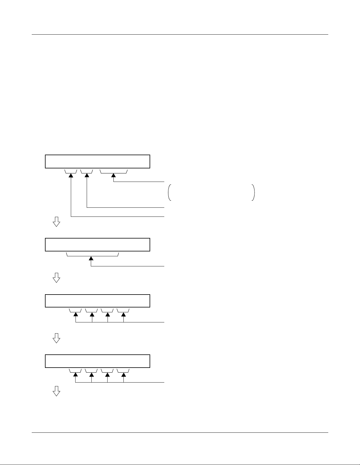
(CAT). The display format is shown below:
(1) Display Format on CAT/MAT by Command Operation
The fault information is separated into four parts and displayed on four screens.
1ST SCREEN
1: 01 MN MP 00
CPU KIND AND NO. THAT DETECTED THE FAULT
MP 00 : MP
FP 00-03 : FP NO. 0-3
AP 04-15, 20-31 : AP NO. 4-15, 20-31
ALARM KIND (MJ/MN/–)
FAULT OCCURRENCE KIND NO./FAULT RESTORATION KIND NO.
2ND SCREEN
2: 99/10/24 20:31
3RD SCREEN
3: X X X X X X X X
4TH SCREEN
4: X X X X X X X X
TO 1ST SCREEN OF NEXT INFORMATION
DATE AND TIME OF FAULT OCCURRENCE AND RESTORATION
FAULT INFORMATION/
FAULT RESTORATION INFORMATION
FAULT INFORMATION/
FAULT RESTORATION INFORMATION
NEAX2000 IVS2 Maintenance Manual
ND-70926 (E), Issue 1.0
Page 5
Page 14
CHAPTER 1 MAINTENANCE SERVICE FEATURES
Fault Messages
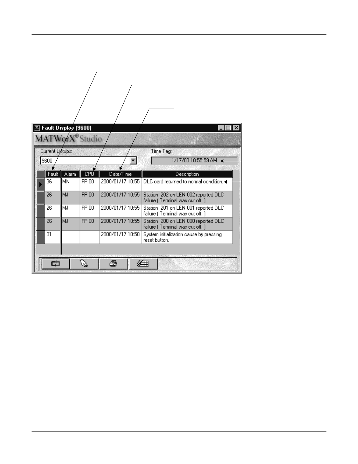
(2) Display Format using MATWorX Studio
The fault information displays in the order that faults occur.
Fault Occurrence Kind No./Fault Restoration Kind No.
CPU Kind and Number : CPU No. Detecting Fault Occurrence/
Date and Time of Fault Occurrence and Restoration:
Year, Month, Date, Time
Fault Restoration
MP, AP xx
Renewal Date of
Fault Content
Fault Information/
Fault Restoration Information
Service Conditions
(1) Printout of fault information is possible through the printer connected to the MAT.
(2) The maximum number of fault information that can be stored is 64. If the stored information
exceeds 64, the storing method (either overwriting new data or no t s toring new data) can
be selected by CM08>451.
(3) To provide external alarm indication, equipment such as an Alarm Display Panel must be
installed. External alarm indication is provided using a contact to ground at the main
distribution frame. One contact is needed for minor alarms, and one contact is needed for
major alarms.
(4) The alarm kind (Majo r Alarm, Minor Al arm, or No Alarm Indicat ion) ca n be prog r ammed b y
CMEA Y=2 for each fault kind.
Page 6
NEAX2000 IVS2 Maintenance Manual
ND-70926 (E), Issue 1.0
Page 15
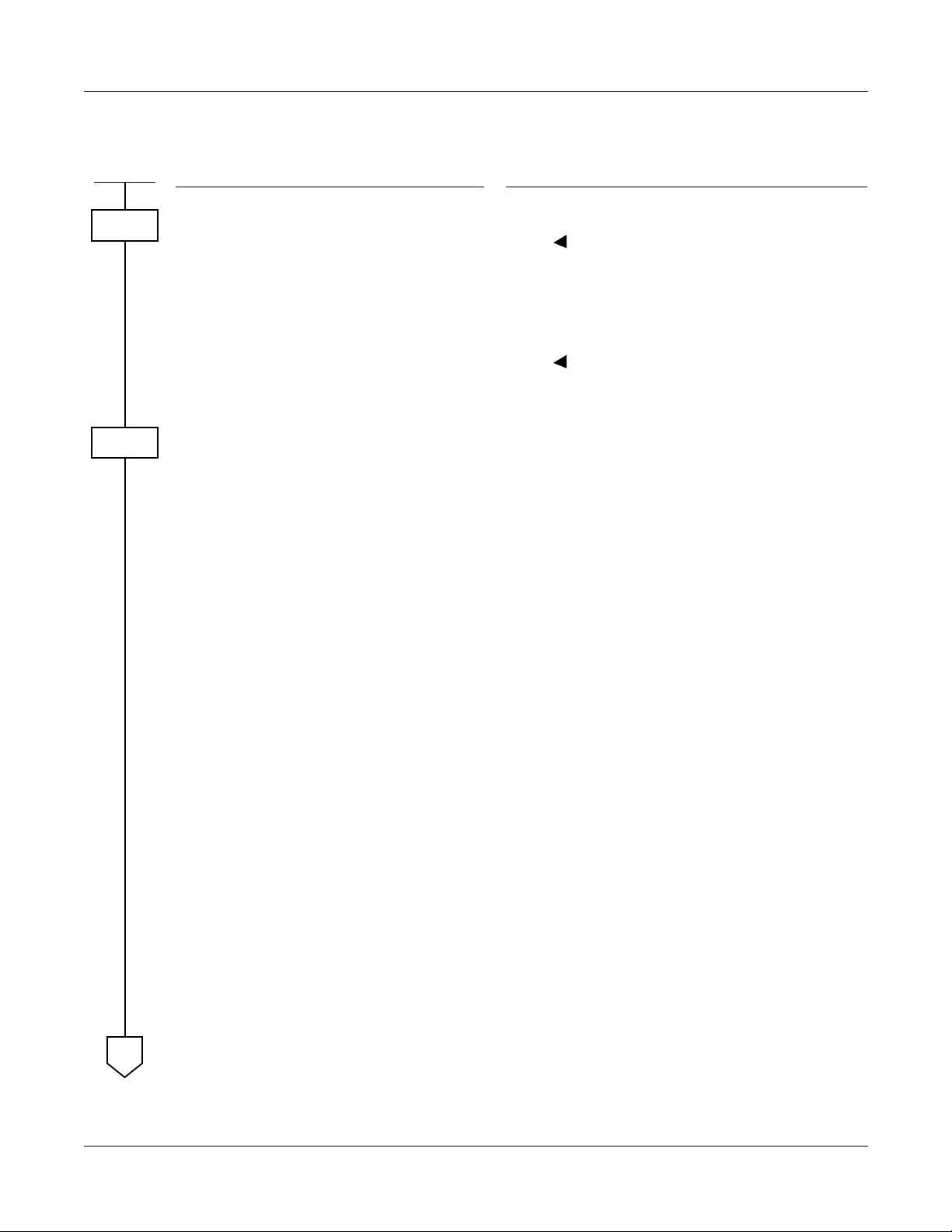
Programming Procedure
CHAPTER 1 MAINTENANCE SERVICE FEATURES
Fault Messages
START
CM08
CMEA
A
DESCRIPTION DATA
Enable the fault information storage
feature.
Specify the processing at the time of
fault stor a ge memory overflow .
Assign which kind of fault information
is stored into the fault information
memory, and which kind of fault indicates an alarm.
NOTE 1:
NOTE 2:
Even if the external alarm
may be set as MN or MJ
alarm for system initialized
(1st data=01), no alarm is
output in th e case of Power
On, Reset key operated, in itialization from the MAT/
CAT, and initialization by
MP SW3 switch selection.
The External Alarm Kind for
“Number of faulty trunks
was more than predetermined number ” is assigned
by CM42>06, 07. When
CM42>06, 07 is assigned,
the 2nd data of CMEA Y=2
simply means the fault info rmation is to be registered
into Fault Memory. In this
case, Alarm K ind ca nn ot be
changed.
(1)
450
(2)
1 : To be provided
(1)
451
(2)
0 : No fault information is registered
in case of fault memory overflow
1 : Fault information is overwritten in
case of fault memory overflow
•
Y=2
(1)
01 : System initialization
NOTE 1
04 : MP-FP/AP communication failure
08 : FP/AP card down
09 : Power failure
12 : CS/ZT fault occurred
16 : Periodic alarm
18 : FP/AP card returned to normal
condition
19 : Power failure returned to normal
condition
20 : DTI line failure
21 : DCH/BRT/PRT D-channel link
connection failure
22 : CCH link connection failure
24 : Number of f aulty trunks w as more
than predetermined number
NOTE 2
[Australia Only]
NEAX2000 IVS2 Maintenance Manual
ND-70926 (E), Issue 1.0
Page 7
Page 16

CHAPTER 1 MAINTENANCE SERVICE FEATURES
Fault Messages
A
CMEA
NOTE 3:
NOTE 4:
DESCRIPTION DATA
The External Alarm Kind for
“Number of lockout stations
was more than predetermined number” is fixed as
MN. The 2nd data of CMEA
Y=2 simply means the fault
information is to be registered into Fault Memory.
In this case, Alarm Kind
cannot be changed.
The External Alarm Kind for
“Number of faulty trunks
was less than predetermined number” is fixed to
No Alarm. The 2nd data of
CMEA Y=2 simply means
that the fault information is
to be registered into Fault
Memory. In this case, Alarm
kind cannot be changed.
(1) 25 : Number of lockout stations was
more than predetermined n umber
NOTE 3
26 : DLC card down
27 : Synchronism of DPC missed
28 : SMDR output buffer memory
overflow
2B : CS/ZT fault occurred
30 : DTI line returned to normal
condition
31 : DCH/BRT/PRT D-channel link
connection returned to normal
condition
32 : CCH link conn ectio n returned to
normal c ondition
34 : Number of faulty trunks was less
than predetermined number
NOTE 4
[Australia Only]
B
Page 8
NEAX2000 IVS2 Maintenance Manual
ND-70926 (E), Issue 1.0
Page 17
CHAPTER 1 MAINTENANCE SERVICE FEATURES
Fault Messages
B
CMEA
NOTE 5:
NOTE 6:
DESCRIPTION DATA
The External Alarm Kind for
“Number of lockout stations
was less than predetermined number” is fixed to
No Alarm. The 2nd data of
CMEA Y=2 simply means
that the fault information is
to be registered into Fault
Memory. In this case, Alarm
Kind cannot be changed.
CMEA programming can be
set using the Fault Storage
add-in of MATWorX.
(1)
35 : Number of lockout stations
restored to less than pre-
deter mined number
36 : DLC card returned to normal
condition
37 : Synchronism of DPC returned to
normal c ondition
38: : SMDR output buffer memory
returned to normal condition
3B : CS/ZT returned to normal
condition
(2)
0 : Fault memory store/No External
Alarm output
1 : Fault memory store/External
Alarm is MN alarm
2 : Fault memory stor e/ External
Alarm is MJ alarm
3 : Fault memory store/External
Alarm Kind is determined by
standard data
NOTE 5
NONE : No fault memory store/No
External Alarm output
CM42
Assign the number of stations in line
lockout to give MN (minor) alarm.
(1)
(2)0101-99 : Number of lockout stations
END
NEAX2000 IVS2 Maintenance Manual
ND-70926 (E), Issue 1.0
Page 9
Page 18

CHAPTER 1 MAINTENANCE SERVICE FEATURES
Fault Messages
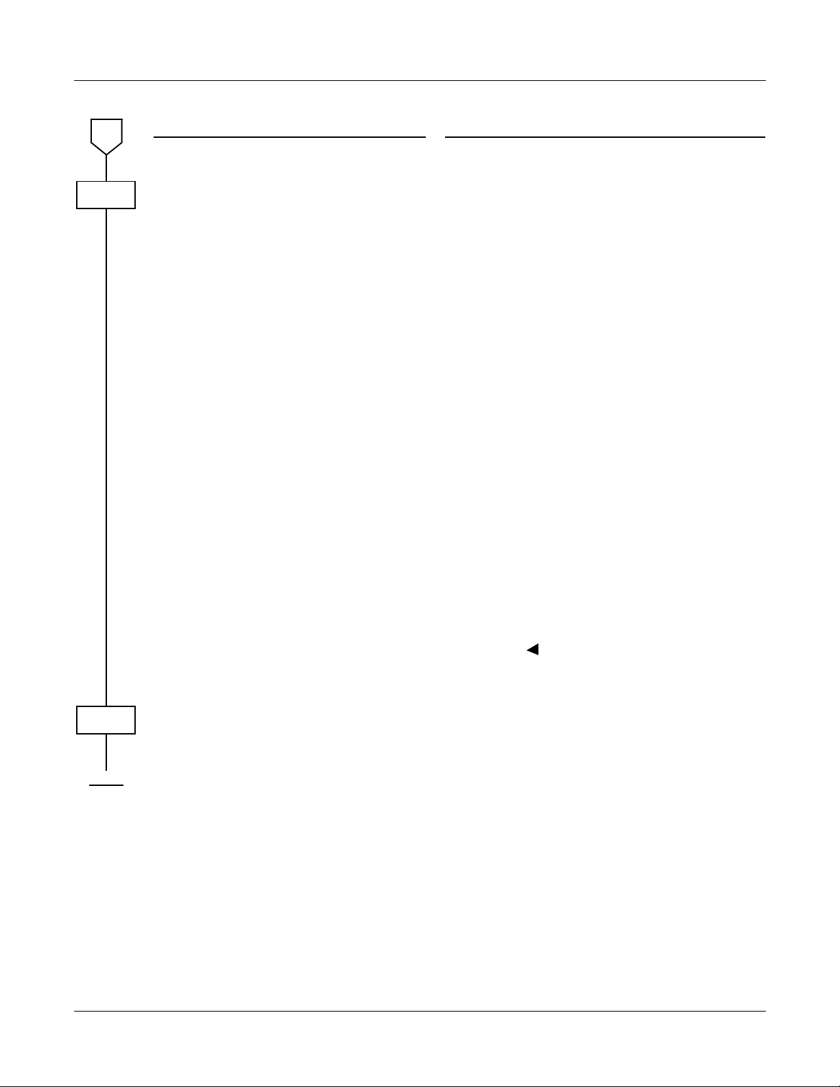
To clear the MJ/MN alarm by external key, perform the following programming.
START
CM10
CM61
DESCRIPTION DATA
Assign the card number for external
key interface (PN-DK00) to the
desired LEN.
NOTE 1:
NOTE 2:
Assign the function of MJ/MN alarm
clear key to the external key.
The card number of th e external key interface (PNDK00) must be assigned to
the first LEN (LEVEL 0) and
third LEN (LEVEL 2) of ea ch
card slot.
Circuit No. 3 of E963 is used
for built-in External Key Interface of MP card by setting CM61.
(1)
000-763: LEN
(2)
E900-E963:
Card No. of external key interface
(PN-DK00)
For PIM0/1: E900-E915
For PIM2/3: E916-E931
For PIM4/5: E932-E947
For PIM6/7: E948-E963
YY=30
•
(1)
XX Z
XX : Card No. of PN-DK00 (00-63)
Z : Circuit No. (0-3)
633 : MP built-in External Key Interface
END
Page 10
(2)
00: MJ/MN alarm clear key
NEAX2000 IVS2 Maintenance Manual
ND-70926 (E), Issue 1.0
Page 19
CHAPTER 1 MAINTENANCE SERVICE FEATURES
Fault Messages
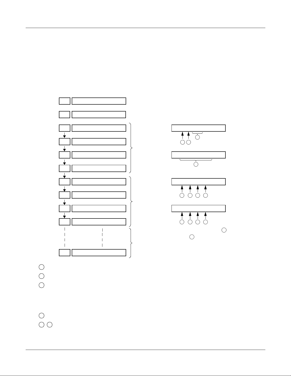
Operating Procedure
(1) To Display Fault Message by CAT
The following flowchart shows the operation procedure for displaying fault messages by
entering a command code (CMEA Y=0) from the CAT or by using the MOC Terminal feature
or the MAT function in the MATWorX Studio.
Operation:
ST
COMMAND=
EA0
00
DE
DE
DE
DE
DE
DE
DE
DE
DE
EA0>
1: 01 – – MP00
2: 99/10/25 13:30
3: F0 FF FF FF
4: FF FF FF FF
1: 20 – – AP 06
2: 99/10/25 16:00
3: F0 FF FF FF
4: FF FF FF FF
INFORMATION 1
INFORMATION 2
INFORMATION 64
1: 01 – – MP00
3
21
2: 99/10/25/13:30
4
3: F0 FF FF FF
65
78
4: F0 FF FF FF
109
11 12
For explanation of data
through , refer to the following
12
1
list.
+
+
DE DATA NOT FOUND
1
:Fault Kind Number (See Table 1-1.)
2
:External Alarm Kind (MJ/MN) (See Table 1-3.)
3
CPU Kind and Number that detected the fault
MP00 : MP
FP00-03 : FP Number 0-3
AP04-15, 20-31 : AP Number 4-15, 20-31
4
:Date and Time of Fault Occurrence and Restoration
12
5
- : Fault Info rmation/Fault Restoration Information (See Table 1-5.)
NEAX2000 IVS2 Maintenance Manual
ND-70926 (E), Issue 1.0
Page 11
Page 20
CHAPTER 1 MAINTENANCE SERVICE FEATURES
Fault Messages
1
:Fault Kind Number
Table 1-1 Fault Occurrence Kind Number
FAULT KIND NUMBER FAULT CONTENT
01 System initialization
04 MP-FP/AP communication failure
08 FP/AP card down
09 Power failu r e
12 CS/ZT fault occurred
16 It is a day for periodic maintenance
20 DTI line failure
21 DCH/BRT/PRT D-channel link connection failure
22 CCH link connection failure
24
[Australia Only]
25 Number of lockout stations was more than predetermined
26 DLC card down
27 Synchronism of DP C mi sse d
28 SMDR output buffer memory overflow
2B CS/ZT fault occurred
Number of faulty trunks was more than predetermined number
number
Page 12
NEAX2000 IVS2 Maintenance Manual
ND-70926 (E), Issue 1.0
Page 21
CHAPTER 1 MAINTENANCE SERVICE FEATURES
Table 1-2 Fault Restoration Kind Number
FAULT KIND NUMBER FAULT RESTORATION CONTENT
18 FP/AP card returned to normal condition
19 Power failure returned to normal condition
30 DTI line returned to normal condition
31 DCH/BRT/PRT D-channel link connection returned to normal
condition
32 CCH link connection returned to normal condition
Fault Messages
34
[Australia Only]
35 Number of lockout stations was less than predetermined number
36 DLC card returned to n ormal condition
37 Synchronism of DPC returned to normal condition
38 SMDR output buffer memory returned to normal condition
3B CS/ZT returned to normal condition
Number of faulty trunks was less than predetermined number
NEAX2000 IVS2 Maintenance Manual
ND-70926 (E), Issue 1.0
Page 13
Page 22

CHAPTER 1 MAINTENANCE SERVICE FEATURES
Fault Messages
2
:External Alarm Kind (MJ/MN/–)
External Alarm Kind—Minor (MN), Major (MJ) , or no alarm (e xternal alarm not pr ovi ded) is
programmed by CMEA Y=2. Table 1-3 shows the standard data set by the 2nd data=3 of
CMEA Y=2.
Table 1-3 Standard Data Set of External Alarm Kind
FAULT
FAULT CONTENT
ALARM
KIND
01 System Initialization MN ALARM
04 MP-FP/AP communication failure MN ALARM
08 FP/AP card down MN ALARM
09 Power failure MJ ALARM
12 CS/ZT fault occurred –
16 It is a day for periodic maintenance –
18 FP/AP card returned to normal condition –
19 Power failure returned to normal condition –
20 DTI line failure MN ALARM
21 DCH/BRT/PRT D-channel link connection failure MN ALARM
22 CCH link connection failure MN ALARM
24
[Australia
Only]
Number of f aulty trunks w as more th an predet ermined num ber M J/MN
ALARM
KIND
Page 14
25 Number of lockout stations was more than predetermined
number (Refer to CM42>01 in Command Manual.)
MN ALARM
(Fixed)
26 DLC card down –
27 Synchronism of DPC missed MN ALARM
28 SMDR output buffer memory overflow MN ALARM
2B CS/ZT fault occurred –
30 DTI line returned to normal condition –
31 DCH/BRT/PRT D-channel link connection returned to normal
–
condition
32 CCH link connection returned to normal condition –
NEAX2000 IVS2 Maintenance Manual
ND-70926 (E), Issue 1.0
Page 23

CHAPTER 1 MAINTENANCE SERVICE FEATURES
Fault Messages
Table 1-3 Standard Data Set of External Alarm Kind (Continued)
FAULT
FAULT CONTENT
KIND
34
[Australia
Only]
35 Number of lockout stations was less than predetermined
36 DLC card returned to normal condition –
37 Synchronism of DPC returned to normal –
38 SMDR output buffer memory returned to normal condition –
3B CS/ZT returned to normal condition –
The alarm lamps in Table 1-4 are indicated according to the alarm kind.
Number of faulty trunks was less than p r edetermined number –
number
Table 1-4 Alarm Kind and Alarm Lamps
ALARM
KIND
–
Alarm Lamp
Alarm Kind
MJ Steady light – Steady light –
MN – Steady lig ht – Steady light
External Alarm
Indication
MJ
External Alarm
Indication
MN
PZ-PW121MJPZ-PW121
MN
NEAX2000 IVS2 Maintenance Manual
ND-70926 (E), Issue 1.0
Page 15
Page 24
CHAPTER 1 MAINTENANCE SERVICE FEATURES
s
Fault Messages
12
5
- : Fault Info rmation/Fault Restoration Information
Table 1-5 Fault Information
FAULT
KIND
NUMBER
5 6 7 8 9
10
11
12
01 Initial Kind,
a
,
b
04 Communication
Failure Kind
d
08
FP/AP No.
e
09 Power Failure
12
Kind 1
Fault Kind AP No.
f f f
g
16 Inspection Kind
j
20 F ault Detail Ki nd
l
21
22
D-ch No.
CCH No.
m
n
24
System Initialization Information
Number of
Communication
Failures
Power Failure
Kind 2
h
c
FP/AP No.
e
Po wer F ail ure
Kind 3
CS/ZT Interface No.
i
25
26 DLC Fai lure
o
Kind
27 DPC Failure
r
Kind
LEN
DPC No.
p
Station No.
q
28 Memory Kind Overflow Kind
t
2B
Page 16
Fault Kind AP No.
v
u
w
CS/ZT Interface No.
x
NEAX2000 IVS2 Maintenance Manual
ND-70926 (E), Issue 1.0
Page 25
FAULT
KIND
NUMBER
18 FP/AP
CHAPTER 1 MAINTENANCE SERVICE FEATURES
Table 1-6 Fault Restoration Information
5 6 7 8 9
e
No.
Fault Messages
10
11
12
19 Power Failure
Kind 1
k k k
30 Fault Detail
31
32
Kind
D-ch No.
CCH No.
l
m
n
34
35
36 DLC Failure
o
Kind
37 DPC Failure
Kind
r
38 Memory
3B
Kind
Faul t Kind AP No. CS/ZT Interface No.
t
y
Power Failure
Kind 2
LEN
DPC No.
z
Power Failure
Kind 3
p
s
Station No.
A
q
NEAX2000 IVS2 Maintenance Manual
ND-70926 (E), Issue 1.0
Page 17
Page 26

CHAPTER 1 MAINTENANCE SERVICE FEATURES
Fault Messages
a
:Kind of System Initialization information (Upp er digit)
1: Program address information
2: Receive command information
F: No system initialization information
:Initial Kind (Lower digit)
b
0: Power On Initialize
1: Initialize by Reset Button (SW1)
2: Serious failure 1
3: Serious failure 2
4: Not used
5: Serious failure 3
6: Serious failure 4
7: Serious failure 5
8: Serious failure 6
9: SW3 was changed to 0
A: Serious failure 7
B: Initialize by CAT/MAT
C: Not used
D: Not used
E: Not used
F: Not used
Page 18
c
:System Initialization Information
The address of the program which caused system initialization
:Communication Failure Kind
d
00: Overflow of data sending buffer to the FP/AP
01: Invalid data received from FP/AP
e
:FP/AP Number
00-03 : FP No. 0-3
04-15, 20-31 : AP No. 4-15, 20-31
NEAX2000 IVS2 Maintenance Manual
ND-70926 (E), Issue 1.0
Page 27

CHAPTER 1 MAINTENANCE SERVICE FEATURES
:Power Failure Kind
f
00: AC input failure
01: Fuse break
02: PWR alarm
g
:Fault Kind
00: Fault notice from CS/ZT
01: CS/ZT initial failure
02: CS/ZT condition read failure
03: CS/ZT condition unmatch
04: B channel condition unmatch
05: SYS-ID upload failure
06: SYS-ID download failure
07: CS/ZT make busy failure
08: CS/ZT data load fa i lur e
09: B channel make busy failure
0A: CS/ZT operation parameter change failure
0B: LCCH sending position failure
0C: Carr ier selection failure
[North America/Latin America Only]
0D: CS/ZT expan si on data re ad failure
0E: CS/ZT expansion data setting failure
0F: CS/ZT operation parameter 2 c hange failure
Fault Messages
:AP No. of CS/ZT fault occurred 04-15, 20-31
h
:CS/ZT Interface No. of fault occurred 000-255
i
j
:Inspection Kind
00: Battery check
:Power Failure Restoration Kind
k
00: AC input failure
01: Fuse break
02: PWR alarm
NEAX2000 IVS2 Maintenance Manual
ND-70926 (E), Issue 1.0
Page 19
Page 28

CHAPTER 1 MAINTENANCE SERVICE FEATURES
Fault Messages
:Fault Detail Kind
l
00: PCM los s
01: Frame loss
02: Multi frame loss
03: AIS error
04: Remote alarm
05: Multi remote alarm
06: S-bit error
07: Not used
08: CRC error
09: Slip detected
0A: Main signal all 1 (for BRT)
0B: INFO 0 (for BRT)
0C: INFO 2 (for BRT)
0D: Not used
0E: Not used
0F: Not used
m
:D-channel Circuit No.
DCH/BRT/PRT: 00-07 =D-channel No. 0-7
n
:CCH No.
00-07=CCH No. 0-7
o
:DLC Failure Kind
00:Termi nal was cut off
02: Short circu it
03: Ring wire was grounded
04: Tip wire was grounded or terminal was unconnected
05: Terminal failure
08: Terminal circuit failure
p
:LEN (000-763)
Page 20
q
:Station No. (X-XXXXXXXX)
NEAX2000 IVS2 Maintenance Manual
ND-70926 (E), Issue 1.0
Page 29

CHAPTER 1 MAINTENANCE SERVICE FEATURES
r
:D PC Failure Kind
00: DPC on the side of partner
01: DPC on the side of oneself
s
:DPC No.
t
:M emory Kind
00: Billing memory block
01: Host CPU No. 0 output Buffer memory block
02: Host CPU No. 1 output Buffer memory block
03: Automatic print Buffer memory block
04: Notice of the rest of memory block numbers in the system
05: CCIS output Buffer memory block
06: CS report traffic data memory block
Fault Messages
u
:Overflow Kind
When setting CMD000>126:0
00: Memory accumulation exceeds the value set by CMD001>229 or CMD003>26-30
01: Mem ory overflowed
When setting CMD000>126:1
01: Memory accumulation exceeds the value set by CMD001>229 or CMD003>26-30
For memory kind 04, regardless of CMD000>126
01: Memory accumulation exceeds the value set by CMD001>229 or CMD003>26-30
v
:Fault Kind
00: CS/ZT connection down
01: CS/ZT carrier has no space
w
:AP No. of CS/ZT fault occurred 04-15, 20-31
x
:CS/ZT Interface No. of CS/ZT fault occurred 000-255
NEAX2000 IVS2 Maintenance Manual
ND-70926 (E), Issue 1.0
Page 21
Page 30

CHAPTER 1 MAINTENANCE SERVICE FEATURES
Fault Messages
y
:Fault Restoration Kind
00: CS/ZT connection returned
01: CS/ZT carrier has space
z
:AP No. returned to normal condition
A
:CS/ZT Interface No. returned to normal condition
Page 22
NEAX2000 IVS2 Maintenance Manual
ND-70926 (E), Issue 1.0
Page 31

(2) To Clear MJ/MN Alarm
•
To clear both MJ/MN ala rms
Operation:
CHAPTER 1 MAINTENANCE SERVICE FEATURES
Fault Messages
ST COMMAND=
•
To clea r MJ alarm only
Operation:
•
To clear MN alarm only
EA1
00
CCC
EA1
01
CCC
DE+EA1>
DE+EA1>00:00 –
EXE+OK
ST COMMAND=
DE+EA1>
DE+EA1>01:01 –
EXE+OK
Operation:
ST COMMAND=
EA1
02
CCC
NEAX2000 IVS2 Maintenance Manual
ND-70926 (E), Issue 1.0
DE+EA1>
DE+EA1>02:02 –
EXE+OK
Page 23
Page 32

CHAPTER 1 MAINTENANCE SERVICE FEATURES
Fault Messages
(3) To Display Fault Messages using MATWorX Studio
Refer to the MATWorX Studio User’s Guide or to the Fault Display online Help in the
MATWorX Studio to display fault messages.
Table 1-5 provides an explanatio n of the 8-byte d ata that appears in the D escription column.
Table 1-7 shows e xamples of f ault occurren ce messages and Table 1-8 shows ex amples of
fault restoration information that the Fault Display add-in may display.
Page 24
NEAX2000 IVS2 Maintenance Manual
ND-70926 (E), Issue 1.0
Page 33

CHAPTER 1 MAINTENANCE SERVICE FEATURES
Table 1-7 Examples of Fault Occurrence Display Using MATWorX
Fault Alarm Date CPU Description
01 - 99/01/08 13:26 MP System initialization
Type : Power On Initialize
Data = (F0 FF FF FF FF FF FF FF)
01 - 99/01/08 13:26 MP System initialization
Type : Initialize by Reset Button (SW1)
Data = (F1 FF FF FF FF FF FF FF)
01 MJ 99/01/08 13:26 MP System initialization
Type : Serious failure 1
Data = (12 23 45 67 89 FF FF FF)
01 MJ 99/01/08 13:26 MP System initialization
Type : Serious failure 2
Data = (13 34 56 78 9A FF FF FF)
01 MJ 99/01/08 13:26 MP System initialization
Type : Serious failure 3
Data = (F5 FF FF FF FF FF FF FF)
01 MJ 99/01/08 13:26 MP System initialization
Type : Serious failure 4
Data = (16 67 89 AB CD FF FF FF)
01 MJ 99/01/08 13:26 MP System initialization
Type : Serious failure 5
Data = (F7 FF FF FF FF FF FF FF)
01 MJ 99/01/08 13:26 MP System initialization
Type : Serious failure 6
Data = (F8 FF FF FF FF FF FF FF)
01 - 99/01/08 13:26 MP System initialization
Type : SW3 Switch was changed to 0
Data = (F9 FF FF FF FF FF FF FF)
01 MJ 99/01/08 13:26 MP System initialization
Type : Serious failure 7
Data = (2A 11 22 33 44 FF FF FF)
01 - 99/01/08 13:26 MP System initialization
Type : Initialize by CAT or MAT
Data = (FB FF FF FF FF FF FF FF)
01 MJ 99/01/08 13:26 MP System initialization
Type : switching
Data = (FC FF FF FF FF FF FF FF)
03 MN 99/01/08 13:26 MP The number of hopper entry was more than the caution level
Hopper kind = H-rank
Data = (F0 FF FF FF FF FF FF FF)
03 MN 99/01/08 13:26 MP The number of hopper entry was more than the caution level
Hopper kind = L-rank
Data = (F1 FF FF FF FF FF FF FF)
Fault Messages
NEAX2000 IVS2 Maintenance Manual
ND-70926 (E), Issue 1.0
Page 25
Page 34

CHAPTER 1 MAINTENANCE SERVICE FEATURES
Fault Messages
Table 1-7 Examples of Fault Occurrence Display Using MATWorX (Continued)
Fault Alarm Date CPU Description
04 MN 99/01/08 13:26 MP MP-FP/AP communication failure
Overflow of data sending buffer to FP/AP. (Count = 10 FP/AP NO. = 04)
Data = (F0 0A 04 FF FF FF FF FF)
04 MN 99/01/08 13:26 MP MP-FP/AP communication failure
Invalid data received from FP/AP. (Count = 96 FP/AP NO. = 07)
Data = (F1 60 07 FF FF FF FF FF)
04 MN 99/01/08 13:26 MP MP-FP/AP communication failure
Invalid data received from FP/AP. (Coun t = 100 or more FP/AP NO. =
11)
Data = (F1 FF 0B FF FF FF FF FF)
08 MN 99/01/08 13:26 MP FP/AP card down
(FP/AP NO. = 52)
Data = (F4 FF FF FF FF FF FF FF)
09 MJ 99/01/08 13:26 MP Power failure
Power Failure Kind : AC input failure
Data = (00 01 02 FF FF FF FF FF)
09 MJ 99/01/08 13:26 MP Power failure
Power Failure Kind : Fuse break
Data = (01 02 00 FF FF FF FF FF)
09 MJ 99/01/08 13:26 MP Power failure
Power Failure Kind : PWR alarm
Data = (02 00 01 FF FF FF FF FF)
12 MN 99/01/08 13:27 MP CS/ZT fault occurred
Fault kind : Fault notice from CS/ZT (CS/ZT No. = 10)
Data = (00 04 00 10 31 01 FF FF)
12 MN 99/01/08 13:27 MP CS/ZT fault occurred
Fault kind : CS/ZT initial failure (CS/ZT No. = 10)
Data = (01 04 00 10 31 01 FF FF)
12 MN 99/01/08 13:27 MP CS/ZT fault occurred
Fault kind : CS/ZT condition read failure (CS/ZT No. = 10)
Data = (02 04 00 10 31 01 FF FF)
12 MN 99/01/08 13:27 MP CS/ZT fault occurred
Fault kind : CS/ZT condition unmatch (CS/ZT No. = 10)
Data = (03 04 00 10 31 01 FF FF)
12 MN 99/01/08 13:27 MP CS/ZT fault occurred
Fault kind : Bch condition unmatch (CS/ZT No. = 10)
Data = (04 04 00 10 31 01 FF FF)
12 MN 99/01/08 13:27 MP CS/ZT fault occurred
Fault kind : SYS-ID upload failure (CS/ZT No. = 10)
Data = (05 04 00 10 31 01 FF FF)
12 MN 99/01/08 13:27 MP CS/ZT fault occurred
Fault kind : SYS-ID download failure (CS/ZT No. = 10)
Data = (06 04 00 10 31 01 FF FF)
12 MN 99/01/08 13:27 MP CS/ZT fault occurred
Fault kind : CS/ZT make busy failure (CS/ZT No. = 10)
Data = (07 04 00 10 31 FF FF FF)
Page 26
NEAX2000 IVS2 Maintenance Manual
ND-70926 (E), Issue 1.0
Page 35

CHAPTER 1 MAINTENANCE SERVICE FEATURES
Fault Messages
Table 1-7 Examples of Fault Occurrence Display Using MATWorX (Continued)
Fault Alarm Date CPU Description
12 MN 99/01/08 13:27 MP CS/ZT fault occurred
Fault kind : CS/ZT data load failure (CS/ZT No. = 10)
Data = (08 04 00 10 31 FF FF FF)
12 MN 99/01/08 13:27 MP CS/ZT fault occurred
Fault kind : Bch make busy failure (CS/ZT No. = 10)
Data = (09 04 00 10 31 FF FF FF)
12 MN 99/01/08 13:27 MP CS/ZT fault occurred
Fault kind : CS/ZT operation parameter change failure (CS/ZT No. = 0)
Data = (0A FF FF 10 31 FF FF FF)
12 MN 99/01/08 13:27 MP CS/ZT fault occurred
Fault kind : LCCH sending position failure (CS/ZT No. = 0)
Data = (0B FF FF 10 31 FF FF FF)
12 MN 99/01/08 13:27 MP CS/ZT fault occurred
Fault kind : Carrier selection failure (CS/ZT No. = 0)
Data = (0C FF FF 10 31 FF FF FF)
12 MN 99/01/08 13:27 MP CS/ZT fault occurred
Fault kind : CS/ZT expansion data read failure (CS/ZT No. = 0)
Data = (0D 01 FF 10 31 FF FF FF)
12 MN 99/01/08 13:27 MP CS/ZT fault occurred
Fault kind : CS/ZT expansion data setting failure (CS/ZT No. = 0)
Data = (0E FF FF 10 31 FF FF FF)
12 MN 99/01/08 13:27 MP CS/ZT fault occurred
Fault kind : CS/ZT operation parameter 2 cha nge failure (CS/ZT No. =
0)
Data = (0F FF FF 10 31 FF FF FF)
12 MN 99/01/08 13:27 MP CS/ZT fault occurred
Fault kind : (CS/ZT No. = 0)
Data = (10 FF FF 10 31 FF FF FF)
16 MN 99/01/08 19:30 MP It is a day for periodic maintenance
Battery check (TK = 0)
Data = (F8 FF FF FF FF FF FF FF)
20 MJ 99/01/08 13:28 AP 5 DTI line failure
PCM loss
Data = (F0 FF FF FF FF FF FF FF)
20 MJ 99/01/08 13:28 AP 5 DTI line failure
Frame loss
Data = (F1 FF FF FF FF FF FF FF)
20 MJ 99/01/08 13:28 AP 5 DTI line failure
Multi frame loss
Data = (F2 FF FF FF FF FF FF FF)
20 MJ 99/01/08 13:28 AP 5 DTI line failure
AIS error
Data = (F3 FF FF FF FF FF FF FF)
20 MJ 99/01/08 13:28 AP 5 DTI line failure
Remote alarm
Data = (F4 FF FF FF FF FF FF FF)
NEAX2000 IVS2 Maintenance Manual
ND-70926 (E), Issue 1.0
Page 27
Page 36

CHAPTER 1 MAINTENANCE SERVICE FEATURES
Fault Messages
Table 1-7 Examples of Fault Occurrence Display Using MATWorX (Continued)
Fault Alarm Date CPU Description
20 MJ 99/01/08 13:28 AP 5 DTI line failure
Multi remote alarm
Data = (F5 FF FF FF FF FF FF FF)
20 MJ 99/01/08 13:28 AP 5 DTI line failure
S-bit error
Data = (F6 FF FF FF FF FF FF FF)
20 MJ 99/01/08 13:28 AP 5 DTI line failure
CRC error
Data = (F8 FF FF FF FF FF FF FF)
20 MJ 99/01/08 13:28 AP 5 DTI line failure
Slip detect ed
Data = (F9 FF FF FF FF FF FF FF)
20 MJ 99/01/08 13:28 AP 5 DTI line failure
Main signal all 1
Data = (FA 01 FF FF FF FF FF FF)
20 MJ 99/01/08 13:28 AP 5 DTI line failure
INFO 0
Data = (FB FF FF FF FF FF FF FF)
20 MJ 99/01/08 13:28 AP 5 DTI line failure
INFO 2
Data = (FC FF FF FF FF FF FF FF)
21 MN 99/01/08 13:28 AP 6 DCH/BRT/PRT D-channel link connection failure
(D-ch NO. = 3)
Data = (03 FF FF FF FF FF FF FF)
22 MN 99/01/08 13:28 AP 7 CCH link connection failure
(CCH NO. = 3)
Data = (03 FF FF FF FF FF FF FF)
24 MN 99/01/08 13:26 FP 0 Number of faulty trunks was more than predetermined number
Data = (FF FF FF FF FF FF FF FF)
25 MN 99/01/08 13:26 M P Numb er of lockout stations was more than predetermined number
Data = (FF FF FF FF FF FF FF FF)
26 MN 99/01/08 13:28 FP 1 DLC card down
DLC Failure Kind : Terminal was cut off (Station number = 2000)
Data = (00 00 80 20 00 FF FF FF)
26 MN 99/01/08 13:28 FP 1 DLC card down
DLC Failure Kind : Short circuit (Station number = 2000)
Data = (02 00 80 20 00 FF FF FF)
26 MN 99/01/08 13:28 FP 1 DLC card down
DLC Failure Kind : Ring wire was grounded (Station number = 2000)
Data = (03 00 80 20 00 FF FF FF)
26 MN 99/01/08 13:28 FP 1 DLC card down
DLC Failure Kind : Tip wire was grounded or terminal was unconnected
(Station number = 2000)
Data = (04 00 80 20 00 FF FF FF)
Page 28
NEAX2000 IVS2 Maintenance Manual
ND-70926 (E), Issue 1.0
Page 37

CHAPTER 1 MAINTENANCE SERVICE FEATURES
Fault Messages
Table 1-7 Examples of Fault Occurrence Display Using MATWorX (Continued)
Fault Alarm Date CPU Description
26 MN 99/01/08 13:28 FP 1 DLC card down
DLC Failure Kind : Terminal failure (Station number = 2000)
Data = (05 00 80 20 00 FF FF FF)
26 MN 99/01/08 13:28 FP 1 DLC card down
DLC Failure Kind : Terminal not connected (Station number = 2000)
Data = (06 00 80 20 00 FF FF FF)
26 MN 99/01/08 13:28 FP 1 DLC card down
DLC Failure Kind : Terminal circuit failure (Station number = 2000)
Data = (08 00 80 20 00 FF FF FF)
27 MN 99/01/08 13:27 FP 0 Synchronism of DPC missed
DPC on the side of a partner (DPC Number = 0001FFFF)
Data = (00 00 01 FF FF FF FF FF)
27 MN 99/01/08 13:27 FP 0 Synchronism of DPC missed
DPC on the side of oneself (DPC Number = 0005FFFF)
Data = (01 00 05 FF FF FF FF FF)
28 MN 99/01/08 13:28 AP 10SMDR output buffer memory overflow
(Memory Kind = 00 Overflow kind : External relay turns ON and OFF)
Data = (00 00 FF FF FF FF FF FF)
2B MN 99/01/08 13:27 MP CS/ZT fault occurred
Fault kind : CS/ZT connection down (CS/ZT No. = 10)
Data = (00 04 00 10 31 01 FF FF)
2B MN 99/01/08 13:27 MP CS/ZT fault occurred
Fault kind : CS/ZT carrier has no space (CS/ZT No. = 10)
Data = (01 04 00 10 FF FF FF FF)
NEAX2000 IVS2 Maintenance Manual
ND-70926 (E), Issue 1.0
Page 29
Page 38

CHAPTER 1 MAINTENANCE SERVICE FEATURES
Fault Messages
Table 1-8 Example of Fault Restoration Display Using MATWorX
Fault Alarm Date CPU Description
18 - 99/01/08 13:26 MP FP/AP card returned to normal condition
(FP/AP NO. = 52)
Data = (F4 FF FF FF FF FF FF FF)
19 - 99/01/08 13:26 MP Power failure returned to normal condition
Recover Kind : AC input failure
Data = (00 01 02 FF FF FF FF FF)
19 - 99/01/08 13:26 MP Power failure returned to normal condition
Recover Kind : fuse break
Data = (01 02 00 FF FF FF FF FF)
19 - 99/01/08 13:26 MP Power failure returned to normal condition
Recover Kind : PWR alarm
Data = (02 00 01 FF FF FF FF FF)
30 - 99/01/08 13:28 AP 5 DTI line returned to normal condition
PCM loss
Data = (F0 FF FF FF FF FF FF FF)
30 - 99/01/08 13:28 AP 5 DTI line returned to normal condition
Frame loss
Data = (F1 FF FF FF FF FF FF FF)
30 - 99/01/08 13:28 AP 5 DTI line returned to normal condition
Multi frame loss
Data = (F2 FF FF FF FF FF FF FF)
30 - 99/01/08 13:28 AP 5 DTI line returned to normal condition
AIS error
Data = (F3 FF FF FF FF FF FF FF)
30 - 99/01/08 13:28 AP 5 DTI line returned to normal condition
Remote alarm
Data = (F4 FF FF FF FF FF FF FF)
30 - 99/01/08 13:28 AP 5 DTI line returned to normal condition
Multi Remote alarm
Data = (F5 FF FF FF FF FF FF FF)
30 - 99/01/08 13:28 AP 5 DTI line returned to normal condition
S-bit error
Data = (F6 FF FF FF FF FF FF FF)
30 - 99/01/08 13:28 AP 5 DTI line returned to normal condition
CRC error
Data = (F8 FF FF FF FF FF FF FF)
30 - 99/01/08 13:28 AP 5 DTI line returned to normal condition
Slip detect ed
Data = (F9 FF FF FF FF FF FF FF)
30 - 99/01/08 13:28 AP 5 DTI line returned to normal condition
Main signal all 1
Data = (FA 01 FF FF FF FF FF FF)
30 - 99/01/08 13:28 AP 5 DTI line returned to normal condition
INFO 0
Data = (FB FF FF FF FF FF FF FF)
30 - 99/01/08 13:28 AP 5 DTI line returned to normal condition
INFO 2
Data = (FC FF FF FF FF FF FF FF)
Page 30
NEAX2000 IVS2 Maintenance Manual
ND-70926 (E), Issue 1.0
Page 39

CHAPTER 1 MAINTENANCE SERVICE FEATURES
Fault Messages
Table 1-8 Example of Fault Restoration Display Using MATWorX (Continued)
Fault Alarm Date CPU Description
31 - 99/01/08 13:28 AP 6 DCH/BRT/PRT D-channel link connection returned to normal condition
(D-ch NO. = 3)
Data = (03 FF FF FF FF FF FF FF)
32 - 99/01/08 13:28 AP 7 CCH link connection returned to normal condition
(CCH NO. = 3)
Data = (03 FF FF FF FF FF FF FF)
34 - 99/01/08 13:26 FP 0 Number of faulty trunks was less than predetermined number
Data = (FF FF FF FF FF FF FF FF)
35 - 99/01/08 13:26 MP Number of lockout stations was less than predetermined number
Data = (FF FF FF FF FF FF FF FF)
36 - 99/01/08 13:28 FP1 DLC card returned to normal condition
Recover Kind No. : 0 (Station number = 200015)
Data = (00 00 80 20 00 15 FF FF)
36 - 99/01/08 13:28 FP1 DLC card returned to normal condition
Recover Kind No. : 2 (Station number = 200016)
Data = (02 00 80 20 00 16 FF FF)
36 - 99/01/08 13:28 FP1 DLC card returned to normal condition
Recover Kind No. : 3 (Station number = 200017)
Data = (03 00 80 20 00 17 FF FF)
36 - 99/01/08 13:28 FP1 DLC card returned to normal condition
Recover Kind No. : 4 (Station number = 200020)
Data = (04 00 80 20 00 20 FF FF)
36 - 99/01/08 13:28 FP1 DLC card returned to normal condition
Recover Kind No. : 5 (Station number = 200021)
Data = (05 00 80 20 00 21 FF FF)
36 - 99/01/08 13:28 FP1 DLC card returned to normal condition
Recover Kind No. : 6 (Station number = 200022)
Data = (06 00 80 20 00 22 FF FF)
36 - 99/01/08 13:28 FP1 DLC card returned to normal condition
Recover Kind No. : 8 (Station number = 200023)
Data = (08 00 80 20 00 23 FF FF)
37 - 99/01/08 13:27 FP0 Synchronism of DPC returned to normal condition
DPC on the side of a partner (DPC Number = 0001FFFF)
Data = (00 00 01 FF FF FF FF FF)
37 - 99/01/08 13:27 FP0 Synchronism of DPC returned to normal condition
DPC on the side of oneself (DPC Number = 0005FFFF)
Data = (01 00 05 FF FF FF FF FF)
38 - 99/01/08 13:28 AP 10SMDR output buffer memory returned to normal condition
(Memory Kind = 00)
Data = (00 FF FF FF FF FF FF FF)
3B - 99/01/08 13:27 MP CS/ZT returned to normal condition
Fault kind : CS/ZT connection returned (CS/ZT No. = 10)
Data = (00 04 00 10 31 01 FF FF)
3B - 99/01/08 13:27 MP CS/ZT returned to normal condition
Fault kind : CS/ZT carrier has space (CS/ZT No. = 10)
Data = (01 04 00 10 FF FF FF FF)
NEAX2000 IVS2 Maintenance Manual
ND-70926 (E), Issue 1.0
Page 31
Page 40

CHAPTER 1 MAINTENANCE SERVICE FEATURES
Station Line Status Display
STATION LINE STATUS DISPLAY
General Description
This feature displays the line s tatus for a single line te lephone or a D
term
using the CAT or the
MAT.
Service Conditions
(1) This feature is not available when the system is off-line.
(2) When performing this feature for a single line telephone, this feature may affect the status
of the other teleph one in the sam e line circui t card. There f ore , use th is f eatu re only when a
line fault has occurred (do not use under a normal state).
Programming Procedure
No program m i ng is required.
Operating Procedure
Operation:
ST COMMAND=
EC1
X-XXXXXXXX
(Station N o.)
DE+EC1>
DE+XXXXXXXX : XX XX XX
Explanation of Screen Informat ion:
1
Station Number: X-XXXXXXXX (1-8 digits)
Page 32
XXXXXXXX : XX XX XX
1
NEAX2000 IVS2 Maintenance Manual
ND-70926 (E), Issue 1.0
4
2
3
Page 41

2
Analog Line/Digital Line
00: LC (Single Line Telephone)
term
10: DLC (D
3
Hardware Test
)
See Table 1-9.
CHAPTER 1 MAINTENANCE SERVICE FEATURES
Station Line Status Display
INDICATION
00 Terminal is not connected. Terminal is not connected, or
01 Terminal is connected. Terminal is connecte d.
02 Loop (Shor t circuit is made
03 Ring wire is grounded Ring wire is grounded.
04 LC card is not mounted. DLC card is not mounted.
05 Test busy Terminal Failure
06 – DLC card down
07 ––
08 – Line failure detected
Table 1-9 Status of Single Line Telephone and D
STATUS OF SINGLE
LINE TELEPHONE
on the line.)
STATUS OF D
Tip wire is grounded.
Short circuit is made on the
line.
term
term
REMARKS
4
Software Test
01 - FF: See Table 1-10. (This data is the same as the status code of CMF5.)
NEAX2000 IVS2 Maintenance Manual
ND-70926 (E), Issue 1.0
Page 33
Page 42

CHAPTER 1 MAINTENANCE SERVICE FEATURES
Battery Release Control
BATTERY RELEASE CONTROL
General Description
When the A C po we r is to be cut off inten tion ally (such as mai ntena nce f o r the b ui lding ), thi s f eature can disconnect the batteries fro m the PBX, u sing the M AT or the CAT, and prev e nt an e xcessive discharge of the ba ttery.
Figure 1-1 System Diagram of Battery Release Control
PBX
C.O.
NETWORK
MODEM
MAT
BATTERY
PWR
ENTERING COMMAND
MODEM
MP
BATTERY CONNECTION RELAY
Service Conditions
The battery disconnection is canceled if the system is initialized (Power off/on or Reset).
Programming Procedure
No program m i ng is required.
Page 34
NEAX2000 IVS2 Maintenance Manual
ND-70926 (E), Issue 1.0
Page 43

Operating Procedure
(1) To disconnect the battery
ST COMMAND=
CHAPTER 1 MAINTENANCE SERVICE FEATURES
Battery Release Control
EC0
00
DE+EC0>
DE+EC0>00:1 –
EXE+EC0>00:1 – 0
0
OK
(2) To cancel the battery disconnection
ST COMMAND=
EC0
00
DE+EC0>
DE+EC0>00:0 –
EXE+EC0>00:0 – 1
1
OK
The current status displays after entering first data 00
(1: Battery connection)
The status changes to battery disconnection after
entering second data 0.
The current status displays after entering first data 00
(0: Battery disconnection)
The status change s to b attery connectio n after enter ing
second data 1.
NEAX2000 IVS2 Maintenance Manual
ND-70926 (E), Issue 1.0
Page 35
Page 44

CHAPTER 1 MAINTENANCE SERVICE FEATURES
Station/Trunk Status Display
STATION/TRUNK STATUS DISPLAY
General Description
This feature allows station/trunk connection status to be displayed on the MAT. If the status is abnormal, this feature can forcibly release the connection using th e MOC Terminal feature of M ATWorX or the CAT.
Service Conditions
(1) Printout of connection status or execution report of forced release is available through the
printer connected to the MAT.
(2) This feature is available for the following items:
• Trunk number (analog trunks)
• Station number
• Virtual station number (Except for Intercom/Attendant position loop line.)
(3) The MAT continues to scan and update the latest con nection status on the screen on a rea l-
time basis.
Page 36
NEAX2000 IVS2 Maintenance Manual
ND-70926 (E), Issue 1.0
Page 45

CHAPTER 1 MAINTENANCE SERVICE FEATURES
Programming Procedure
No program m i ng is required.
Operating Procedure
(1) To display Station/Trunk Status:
Refer to the MATWorX Studio User’s Guide.
(2) To forcibly release the station/trunk connection:
Operation:
ST COMMAND=
Station/Trunk Status Display
EB0
DXXX
(Trunk No.)
EB2
X-XXXXXXXX
(Station No.)
FX-FXXXXXXXX
term
No.)
(D
DE+EB0>
DE+XXX : CCC
Trunk No.
ST COMMAND=
DE+EB2>
DE+XXXXXXXX : CCC
Station No.
NEAX2000 IVS2 Maintenance Manual
ND-70926 (E), Issue 1.0
Page 37
Page 46

CHAPTER 1 MAINTENANCE SERVICE FEATURES
Diagnostics
DIAGNOSTICS
General Description
To assist maintenance personnel, this feature provides diagnostic capabilities such as fault code
generation, device status information and alarm information recording, which can be accessed
from the MAT or the CAT.
Service Conditions
(1) The following station status information can be displayed on the MAT or the CAT by direct
command:
• Idle
• Line Lockout
• Dialing
• Tone Trunk Connection (reorder tone, busy tone, service set tone, etc.)
• Types of Connection (station-to-station, three-way calling, voice calling, holding, etc.)
• Destination number (trunk number, register number)
• Short circuit on line
(2) The following trunk status information can be displayed on the MAT or the CAT by direct
command:
• Idle
• Ringing in
• Incoming queue to Attendant Console
• Holding
• In a tandem connection
• Incoming queue to UCD
• Dialing
• Receiving dialed digits
Page 38
NEAX2000 IVS2 Maintenance Manual
ND-70926 (E), Issue 1.0
Page 47

CHAPTER 1 MAINTENANCE SERVICE FEATURES
Diagnostics
(3) The following information is st ored and can be displayed on the MAT or the CAT using a
memory dump command in hexadecimal format:
• Program address where an endless loop has occurred
• Last initialization time for main program
• Last initialization time for firmware program
• The reason for initialization (power-on,
RESET
key, endless loop, rotary switch, command
from MAT or CAT)
(4) The PBX has a built-in patrol program that monitors the status of all connected devices.
Additionally, when no response or an invalid response from a device is received, this
program stores in memory the slot number of that device. From the MAT or the CAT, a
maintenance person can read the slot number of any device that does not respond to the
main processor or provides an illegal status to the main processor.
Programming Procedure
No program m i ng is required.
Operating Procedure
(1) Station Status Information
Operation:
ST COMMAND=
F50
0 + X-XXXXXXXX
(Station N o.)
(D
term
or
No.)
0 + FX-FXXXXXXXX
DE+F50>
DE+XXXX : XX XX XX XX
Status Code of the designated Address +3
Status Code of the designated Address +2
Status Code of the designated Address +1
Status Code of the designated Address
Designated Address
For the meaning of status code, see Table 1-10.
NEAX2000 IVS2 Maintenance Manual
ND-70926 (E), Issue 1.0
Page 39
Page 48

CHAPTER 1 MAINTENANCE SERVICE FEATURES
Diagnostics
Table 1-10 Station Status Information
STATUS
DESCRIPTION REMARKS
CODE
01 Idle
02 In Line Lockout mode
10 Dialing to an ORT
11 Dialing to a trunk
12 Dialing to an ORT (After consultation hold a s tation)
13 Dialing to an ORT (After consultation hold a trunk)
14 Dialing to a trunk (After consultation hold a station)
15 Dialing to a trunk (After consultation hold a trunk)
1F Dialing to an ORT (After consultation hold 3 party Confer-
ence Trunk)
20 In Reorder Tone connection
21 In Reorder Tone c onnection (While con sultation hold a
Station)
22 In Reorder Tone connection (While consu l tat io n h old a trunk)
23 In Reorder Tone connection (While consultation hold 3 party
Conference Trunk)
2C In Howler Tone connection
30 In Service Set tone connection
32 In Service Set tone connection (While consultation hold a
trunk)
40 In Ringback Tone Connection
41 In Ringback Tone Connection for the second call
(After consultation hold a station)
42 In Ringback Tone connection fo r the second call
(After consultation hold a trunk)
44 In Ringback Tone connection for the operator call
45 In Ringback Tone connection for operator call
(After consultation hold a station)
Page 40
NEAX2000 IVS2 Maintenance Manual
ND-70926 (E), Issue 1.0
Page 49

CHAPTER 1 MAINTENANCE SERVICE FEATURES
Table 1-10 Station Status Information (Continued)
Diagnostics
STATUS
DESCRIPTION REMARKS
CODE
46 In Ringback Tone connection for operator call
(After consultation hold a trunk)
50 Ringing (Call from a station)
51 Ringing (Call from an outside party)
55 Ringing (Automatic Wake Up Call)
60 In Station to Station connection
62 In 3 Way Ca lling
65 Holding
66
Voice Call to a D
67 Voice Call from a Station
71 In Statio n to Trunk connect i on
72 Three-way calling with a station and a trunk
term
NOTE:
C4
In a CAT mode (For D
term
)
C8 In a UCD Queue
C9 In a UCD Queue after holding a station
CA In a UCD Queue after holding a trunk
The status codes not described in this table mean busy conditions.
NEAX2000 IVS2 Maintenance Manual
ND-70926 (E), Issue 1.0
Page 41
Page 50

CHAPTER 1 MAINTENANCE SERVICE FEATURES
Diagnostics
(2) Trunk Status Information
Operation:
ST COMMAND=
F50
0 + DXXX
(Trunk No.)
DE+F50>
DE+XXXX : XX XX XX XX
Status Code of the designated Address +3
Status Code of the designated Address +2
Status Code of the designated Address +1
Status Code of the designated Address
Designated Address
For the meaning of status code, see Table 1-11.
Page 42
NEAX2000 IVS2 Maintenance Manual
ND-70926 (E), Issue 1.0
Page 51

CHAPTER 1 MAINTENANCE SERVICE FEATURES
Table 1-11 Trunk Status Information
Diagnostics
STATUS
CODE
01 Incoming queue to Attendant Console
03 Attendant Camp On
04 In a trun k to station connection
05 Dialing In (Tie Line)
06 In a tandem connection
08 Hold by Exclusive/Nonexclusive Hold
09 TAS in progress
0A Incoming queue to UCD
0B Threeway Calling with a station and two trunks
0D In Ringback To ne/Busy Tone connection (Tie Line)
0E Waiting for release signal from d istant office
10 Sending dialed digits (Outgoing Trunk of a tandem
connection)
DESCRIPTION REMARKS
11 Threeway calling with two stations
14 Dialing In (Incoming Trunk of a trunk to trun k connection)
19
Ringing In (Trunk Direct Appearance on D
term
)
1A Ringing In (Direct In Termination-DIT)
1B Ringing In (Trunk Direct Appearance and DIT)
20 Holding by Call Hold
21 Holding by Call Park
2A Incoming Queue to UCD (While se nding message)
2B Incoming Queue to UCD (After sending message)
FF Idle
NEAX2000 IVS2 Maintenance Manual
ND-70926 (E), Issue 1.0
Page 43
Page 52

CHAPTER 1 MAINTENANCE SERVICE FEATURES
Diagnostics
(3) Alarm Information
Operation:
ST COMMAND=
F53
XXXX
(Memory Dump Data)
DE+F53>
DE+XXXX : XX XX XX XX
See Table 1-12.
Designated Address
Page 44
NEAX2000 IVS2 Maintenance Manual
ND-70926 (E), Issue 1.0
Page 53

CHAPTER 1 MAINTENANCE SERVICE FEATURES
Table 1-12 Alarm Information
Diagnostics
MEMORY DUMP
DA T A
0000 Last Initialization Time for Main Processor (MP)
0001 Reason for System Initialization
ALARM INFORMATION REMARKS
DD HH MM SS
Second (00-59)
Minute (00-59)
Hour (00-23)
Date (01-31)
00: Power on
01: SW1 on MP card
02: Endless Loop in H-Rank
03: Endless Loop in L-Rank
05: Stack Trouble
06: Address Trouble
07: COP Alarm
08: Abor t
09: SW3 on MP card
0B: Command from MAT/CAT
No fault
System fault
No fault
0004 Last Initialization Time for Firmware Processor (FP0-
FP3)
DD HH MM SS
Second (00-59)
Minute (00-59)
Hour (00-23)
Date (01-31)
NOTE:
Press the key to display the next FP data.
S
NEAX2000 IVS2 Maintenance Manual
ND-70926 (E), Issue 1.0
Page 45
Page 54

CHAPTER 1 MAINTENANCE SERVICE FEATURES
Battery Replacement
BATTERY REPLACEMENT
The interval of battery replacement depends on the ambient temperature.
The following caution label, which is attached to the reverse side of the Fr o nt Cover for PIM and
BATTM, shows battery replacement intervals.
When you set u p the b attery fo r the first time , record the insta llation da te . Refer to the BATTERY
REPLACEMENT TABLE for the recommended periods to replac e the battery.
BATTERY REPLACEMENT TABLE
INSTALLATION DATE:
AMBIENT
TEMPERATURE
REPLACEMENT
INTERVAL
o ELECTROLYTE LEAKAGE OR OTHER HAZARDS
MAY RESULT IF THE BATTERY IS NOT REPLACED
IN ACCORDANCE WITH THE SPECIFIED INTERVALS.
5 ~ 35°C
(AVERAGE 25°C)
3 YEARS 1 YEAR
0 ~ 50°C
(AVERAGE 25°C)
2 YEARS
0 ~ 50°C
(AVERAGE 40°C)
CAUTION
o DO NOT STRIKE A MATCH OR CAUSE A SPARK
IN VICINITY OF BATT ERY.
o PLACE THE EQUIPMENT IN WELL
VENTILATED AREA .
o DO NOT SHORT.
o REPLACE BATTERY ONLY AFTER BATTERY
GASES HAVE BEEN DIS PERSED.
TO PREVENT INJURY AND SKIN BURN,
PAY ATTENTION TO THE FOLLOWING.
Page 46
NEAX2000 IVS2 Maintenance Manual
ND-70926 (E), Issue 1.0
Page 55

PERIODIC ALARM
General Description
CHAPTER 1 MAINTENANCE SERVICE FEATURES
Periodic Alarm
This feature can indicate t h e al arm on the D
term
function key or external alarm display panel for
periodic inspection.
The PBX controls the time of periodic inspection, and when the time (assigned by CM43 Y=2)
comes, indicates the alarm.
Figure 1-2 Periodic Alarm Indications
PBX
MP
Record the time of
periodic inspection
panel
MJ MN
1
2
A
B
4
C
G
H
I
D
E
5
J
K
7
L
P
Q
6
R
S
8
T
U
V
9
0
O
P
E
R
#
Indicate the alarm
when the time of
periodic inspection comes
3
F
F
e
a
t
u
r
e
Service Conditions
(1) Use CM43 Y=2 to assign the time (year, month, date, time) of periodic inspection; for
example, batter y exchange.
(2) When the time of periodic inspection comes, the D
setting is the MJ alarm, or flashes with 60 IPM when the setting is the MN alarm. At the
same time, the alarm display panel can indicate the alarm.
(3) Up to two D
term
s in a system can indicate the periodic alarm.
(4) The alarm indication can be cleared by assignin g CMEA Y=1 from CAT/MAT.
NEAX2000 IVS2 Maintenance Manual
ND-70926 (E), Issue 1.0
term
alarm function key lights when the
Page 47
Page 56

CHAPTER 1 MAINTENANCE SERVICE FEATURES
Periodic Alarm
Programming Procedure
START
CM43
CM51
DESCRIPTION DATA
Assign the date and time setting for
periodic alarm.
Assign the battery exchange to
inspection kind.
Specify the D
term
for alarm display.
Y=2
•
(1)
00
(2)
YYYY MM DD HH
YYYY :1999-2050 (Year)
MM :01-12 (Month)
DD :01-31 (Date)
HH :00-23 (Hour)
Y=3
•
(1)
00
(2)
0 : Battery exchange alarm
NONE :No Data
Y=16
•
(1)
(2)
term
01: D
02: D
term
1
2
X-XXXXXXXX (My line number of
term
D
)
CM90
CMEA
END
Assign the alarm indication key to
term
D
function key.
Set the External Alarm Kind to MJ/
MN alarm.
NONE :No Data
Y=00
•
(1)
My line number + +Key number (01-
,
24)
(2)
F5020
Y=2
•
(1)
16
(2)
1: MN alarm
Alarm display
:
2: MJ alarm
Page 48
NEAX2000 IVS2 Maintenance Manual
ND-70926 (E), Issue 1.0
Page 57

•
To clear the alarm display
CHAPTER 1 MAINTENANCE SERVICE FEATURES
Periodic Alarm
START
CMEA
END
DESCRIPTION DATA
Clear the alarm display.
•
Y=1
00: Clear both MJ/MN alarm
01: Clear MJ alarm
02: Clear MN alarm
NEAX2000 IVS2 Maintenance Manual
ND-70926 (E), Issue 1.0
Page 49
Page 58

This page is for your notes.
Page 50
NEAX2000 IVS2 Maintenance Manual
ND-70926 (E), Issue 1.0
Page 59

CHAPTER 2
TROUBLESHOOTING
This chapter describes the precautions and the troubleshooting procedures.
NEAX2000 IVS2 Maintenance Manual
ND-70926 (E), Issue 1.0
Page 51
Page 60

CHAPTER 2 TROUBLESHOOTING
Precautions
PRECAUTIONS
Procedure f or Unplugging/Plugging Cir cuit Cards
When removing a ci rcuit card from the PIM or when mounting a ci rcuit card in the PIM, f oll ow the
procedure in Table 2-1.
Table 2-1 Procedure for Unplugging/Plugging Circuit Cards
PROCEDURE
CIRCUIT CARD
PLUG UNPLUG
CONDITION
PN-CP14 (MP)
•
PZ-PW121 (AC/DC PWR)
•
PZ-PW122 (DC/DC PWR)
•
PZ-M537 (EXPMEM)
•
PN-AP00-A (DBM)
•
PN-AP00-B (AP00)
•
PN-AP01 (AP01)
•
PN-BRTA (BRT)
•
PN-2BRTC (BRT)
•
PN-CP15 (FP)
•
PN-24DTA-C (DTI)
•
PN-30DTC-A (DTI)
•
PN-24PRTA (PRT)
•
PN-PW00 (EXTPWR)
•
PN-4RSTB (MFR)
•
PN-4RSTC (CIR)
•
PN-SC00 (CCH)
•
PN-SC01 (DCH)
•
PN-SC03 (ICH)
•
PN-SC03-A (CSH)
•
(1) Power off
(2) Plug in
(3) Power on
(1) Power off
or MB
switch on
(2) Plug in
(3) Power on
or MB
switch off
(1) Power off
(2) Unplug
(3) Power on
(1) Power off
or MB
switch on
(2) Unplug
(3) Power on
These circuit cards must be
plugged in or unplugged only with
power off to p rev ent damage to the
card or other system circuitry.
These circuit cards must be
plugged in or unplugged under
Make Busy condition or power off
to prevent damage to the card or
other system circuitry.
Page 52
NEAX2000 IVS2 Maintenance Manual
ND-70926 (E), Issue 1.0
Page 61

CHAPTER 2 TROUBLESHOOTING
Static Electricity Guard
You must wear a grounded wrist strap to protect circuit cards from static electricity.
Figure 2-1 Static Electricity Guard (1 of 2)
• WHEN PLUGGING/UNPLUGGING A CIRCUIT CARD
PBX
FRAME GROUND SCREW
WRIST STRAP
Precautions
• WHEN HOLDING A CIRCUIT CARD
NEVER TOUCH THE COMPONENTS OR
SOLDERED SURFACE WITH BARE HANDS.
CARD FRONT
NEAX2000 IVS2 Maintenance Manual
ND-70926 (E), Issue 1.0
Page 53
Page 62

CHAPTER 2 TROUBLESHOOTING
Precautions
Figure 2-1 Static Electricity Guard (2 of 2)
WHEN MAKING A SWITCH SETTING ON A CIRCUIT CARD
•
CIRCUIT
CARD
WEAR A WRIST STRAP AND PERFORM
THE WORK ON A GROUNDED
CONDUCTIVE WORK SURFACE.
WHEN CARRYING A CIRCUIT CARD
•
CIRCUIT
CARD
CONDUCTIVE
POLYETHYLENE
BAG
WHEN CARRYING A CIRCUIT CARD
AROUND, KEEP THE CARD IN A
CONDUCTIVE POLYETHYLENE BAG.
Page 54
NEAX2000 IVS2 Maintenance Manual
ND-70926 (E), Issue 1.0
Page 63

CHAPTER 2 TROUBLESHOOTING
Precautions
CAUTION
You must hold the edge of a circuit card when plugging or unplugging the circuit card. If you
touch another area, you may be exposed to hazardous voltages.
PBX
NEVER TOUCH THE COMPONENTS
OR SOLDERED SURFACE WITH
BARE HANDS.
CARD FRONT
NEAX2000 IVS2 Maintenance Manual
ND-70926 (E), Issue 1.0
Page 55
Page 64

CHAPTER 2 TROUBLESHOOTING
Precautions
Turning Power ON
CAUTION
1. When the operating pow er is being sup plied to the PZ- PW121 card, do not plug/unpl ug this
circuit card into/from its mounting slot.
2. When the system is configured with two or more PIMs, the BUS cab le provides gang con trol
for the PZ-PW121 card of PIM0 and other PIMs. Therefore, if the power of PIM0 is off, no
power is supplied to the whole system even when the power switch(es) of other PIMs are
left on. Note, howe ve r , that the batte ry continues to charge e v en under these c ircumstances.
3. Do not turn off the PZ-PW121 card on PIM1 to PIM7 when the system is operating.
(1) Check the switch position of each PZ-PW121 card before turning power on.
• Make sure that the AC120V/240V selector switch is positioned to appropriate voltage for
each country (AC120V or AC240V).
SW
240V100V/120V
• Make sure that the battery mode selector switch is positioned as shown below to meet the
kind of battery:
SW101
OFF
12
1 : Not used
2 : ON (SEAL/FLOAT2)
OFF (OPEN/FLOAT1)
ON
(2) Turn the SW1 switches of all the PZ-PW121 cards to ON. First, turn ON PIM1 to PIM7.
Then, turn ON PIM0 last of all.
Page 56
NEAX2000 IVS2 Maintenance Manual
ND-70926 (E), Issue 1.0
Page 65

CHAPTER 2 TROUBLESHOOTING
Precautions
Turning Power OFF
(1) Before turning power off, make sure that all line/tr unk cards are not operating by no busy
lamps indication.
(2) Turn the SW1 switches of all the PZ-PW121 cards to O FF. First, turn OFF PIM0. Then, turn
OFF PIM1 to PIM7.
NEAX2000 IVS2 Maintenance Manual
ND-70926 (E), Issue 1.0
Page 57
Page 66

CHAPTER 2 TROUBLESHOOTING
Outline of Troubleshooting
OUTLINE OF TROUBLESHOOTING
Figure 2-2 shows an outline of the recommended troubleshooting procedure.
Figure 2-2 Troubleshooting Outline
START
FAULT DETECTION
FAULT DIAGNOSIS
AND
TROUBLESHOOTING
END
Fault Detection Method (See Page 59.)
(1) Alarm Indication on PWRU, Alarm Display
Panel
(2) Lamp Indication on Circuit Cards
(3) Complaint from station user or operator
Fault Diagnosis and Troubleshooting Method
(1)Display on MAT/CAT (See Page 65.)
Fault Message
•
Station Line Status Display
•
(2)Lamp Indication on Cards
(See Page 83.)
(3)Contents of complaint from station user
or operator (See Page 95.)
Page 58
NEAX2000 IVS2 Maintenance Manual
ND-70926 (E), Issue 1.0
Page 67

CHAPTER 2 TROUBLESHOOTING
Fault Detection
FAULT DETECTION
This section describes the way in which alarm indications are given. If a fault occurs in the system, you can detect the fault via the routes shown in Figure 2-3.
Figure 2-3 Alarm Indication Routes
ALARM DISPLAY PANEL
PWR
MJ/MN ALARM
INDICATION
MAINTENANCE
MJ MN
PWR CARD
MJ
MN
ON
MJ/MN ALARM
INDICATION
PERSONNEL
LAMP INDICATION
CIRCUIT CARD
COMPLAINT FROM
STATION USER OR OPERATOR
NEAX2000 IVS2 Maintenance Manual
ND-70926 (E), Issue 1.0
Page 59
Page 68

CHAPTER 2 TROUBLESHOOTING
Fault Detection
(1) Fault Detection b y Al arm Indication
When a fault occurs in the system, you can detect the fault by a Major (MJ) alarm or Minor
(MN) alarm indicated on the AC/DC PWR card or by the external Alarm Display Panel.
(2) Fault Detection by Lamp Indication on Circuit Cards
When a fault occurs in the system, you can detect the fault by lamp indication on circuit
cards, such as a Major (MJ) or Minor (MN) alarm indicated on the MP card. Table 2-2 iden-
tifies the alarm indication lamps on each ci rcuit card. F or details of l amp indication on circuit
cards, refer to the Installation Procedure Manual.
(3) Fault Detection b y Complaint from Station Use r or Operator
When you receive a complain t about a problem f rom a sta tion us er or an o perator, collect
as much inf ormation on the prob lem as possib le, and th en troublesh oot the prob lem according to the procedure in "Troubleshooting by Contents of Complaint" on Page 95.
Page 60
NEAX2000 IVS2 Maintenance Manual
ND-70926 (E), Issue 1.0
Page 69

CHAPTER 2 TROUBLESHOOTING
Table 2-2 Lamp Indications on Circuit Cards
Fault Detection
KIND OF
CIRCUIT CARD
CARD NAME
LAMP
NAME
COLOR
NORMAL ABNORMAL
INDICATIONS
Control Cards PN-CP14 (MP) RUN Green 120 IPM Flash Steady ON or OFF
PN-CP15 (FP) RUN Green 120 IPM Flash Steady ON or OFF
PN-PW00
RUN Green Steady ON OFF
(EXTPWR)
PZ-PW121
ON Green Steady ON OFF
(AC/DC PWR)
PZ-PW122
ON Green Steady ON OFF
(DC/DC PWR)
Application
Processor Cards
PN-AP00-A
(DBM)
PN-AP00-B
RUN Green 120 IPM Flash Steady ON or OFF
RUN Green 120 IPM Flash Steady ON or OFF
(AP00)
PN-AP01
RUN Green 120 IPM Flash Steady ON or OFF
(AP01)
PN-BRTA (BRT) RUN Green 120 IPM Flash Steady ON or OFF
PN-2BRTC
(BRT)
PN-CC01
(ETHER)
PN-24DTA-C
(DTI)
ALM Red OFF Steady ON
RUN Green 120 IPM Flash Steady ON or OFF
ALM0 Red OFF Steady ON
ALM1 Red OFF Steady ON
RUN Green 60 IPM Flash Steady ON or OFF
RUN Green 120 IPM Flash Steady ON or OFF
AIS Red OFF Steady ON
RMT Red OFF Steady ON
FRM Red OFF Steady ON
PCM Red OFF Steady ON
CRC Red OFF Steady ON
NEAX2000 IVS2 Maintenance Manual
ND-70926 (E), Issue 1.0
Page 61
Page 70

CHAPTER 2 TROUBLESHOOTING
Fault Detection
Table 2-2 Lamp Indications on Circuit Cards (Continued)
KIND OF
CIRCUIT CARD
Application
Processor Cards
INDICATIONS
CARD NAME
PN-30DTC-A
(DTI)
LAMP
COLOR
NAME
RUN Green 120 IPM Flash Steady ON or OFF
AIS Red OFF Steady ON
NORMAL ABNORMAL
MRMT Red OFF Steady ON
RMT Red OFF Steady ON
MFRM Red OFF Steady ON
FRM Red OFF Steady ON
PCM Red OFF Steady ON
PN-24PRT
(PRT )
RUN Green 120 IPM Flash Steady ON or OFF
LC Green Steady ON OFF
AIS Red OFF Steady ON
RMT Red OFF Steady ON
FRM Red OFF Steady ON
PCM Red OFF Steady ON
CRC Red OFF Steady ON
PN-4RSTB
RUN Green 120 IPM Flash Steady ON or OFF
(MFR)
PN-4RSTC
RUN Green 120 IPM Flash Steady ON or OFF
(CIR)
PN-SC00 (CCH) RUN Green 120 IPM Flash Steady ON or OFF
Page 62
LC Green Steady ON OFF
PN-SC01 (DCH) RUN Green 120 IPM Flash Steady ON or OFF
LC Green Steady ON OFF
PN-SC03 (ICH) RUN Green 120 IPM Flash Steady ON or OFF
DOPE0
DOPE1
DOPE2
DOPE3
DOPE4
DOPE5
DOPE6
DOPE7
Green Steady ON OFF
Green Steady ON OFF
Green Steady ON OFF
Green Steady ON OFF
Green Steady ON OFF
Green Steady ON OFF
Green Steady ON OFF
Green Steady ON OFF
NEAX2000 IVS2 Maintenance Manual
ND-70926 (E), Issue 1.0
Page 71

CHAPTER 2 TROUBLESHOOTING
Table 2-2 Lamp Indications on Circuit Cards (Continued)
Fault Detection
KIND OF
CARD NAME
CIRCUIT CARD
Application
Processor Cards
Line /Trunk Cards PN-2COTD
PN-SC03-A
(CSH)
(COT)
[For Australia/
Others]
PN-4COTE
(COT)
[For Australia]
LAMP
INDICATIONS
COLOR
NAME
RUN Green 120 IPM Flash Steady ON or OFF
DOPE0
DOPE1
DOPE2
DOPE3
DOPE4
DOPE5
DOPE6
DOPE7
LF0 Red OFF Steady ON
LF1 Red OFF Steady ON
LF0 Red OFF Steady ON
LF1 Red OFF Steady ON
LF2 Red OFF Steady ON
Green Steady ON OFF
Green Steady ON OFF
Green Steady ON OFF
Green Steady ON OFF
Green Steady ON OFF
Green Steady ON OFF
Green Steady ON OFF
Green Steady ON OFF
NORMAL ABNORMAL
PN-6COTJ
(COT)
[For Australia]
LF3 Red OFF Steady ON
LF0 Red OFF Steady ON
LF1 Red OFF Steady ON
LF2 Red OFF Steady ON
LF3 Red OFF Steady ON
LF4 Red OFF Steady ON
LF5 Red OFF Steady ON
NEAX2000 IVS2 Maintenance Manual
ND-70926 (E), Issue 1.0
Page 63
Page 72

CHAPTER 2 TROUBLESHOOTING
Fault Detection
Table 2-2 Lamp Indications on Circuit Cards (Continued)
KIND OF
CARD NAME
CIRCUIT CARD
Line/Trunk Cards PN-8COTT
(COT)
[For Australia]
PN-2CSIA
(CSI)
[For North
America/
Latin America]
LAMP
INDICATIONS
COLOR
NAME
LF0 Red OFF Steady ON
LF1 Red OFF Steady ON
LF2 Red OFF Steady ON
LF3 Red OFF Steady ON
LF4 Red OFF Steady ON
LF5 Red OFF Steady ON
LF6 Red OFF Steady ON
LF7 Red OFF Steady ON
OPE Green Steady ON OFF
B12 Red ON/OFF 60 IPM Flash
B11 Red ON/OFF 60 IPM Flash
B10 Red ON/OFF 60 IPM Flash
B02 Red ON/OFF 60 IPM Flash
B01 Red ON/OFF 60 IPM Flash
NORMAL ABNORMAL
B00 Red ON/OFF 60 IPM Flash
PN-2CSIA-A
(CSI)
[For Australia/
OPE Green Steady ON OFF
B12 Red ON/OFF 60 IPM Flash
B11 Red ON/OFF 60 IPM Flash
Others]
B10 Red ON/OFF 60 IPM Flash
B02 Red ON/OFF 60 IPM Flash
B01 Red ON/OFF 60 IPM Flash
B00 Red ON/OFF 60 IPM Flash
PN-M03(M03) OPE Green Steady ON OFF
PN-M10(M10) CK0 Green Steady ON OFF
CK1 Green Steady ON OFF
TALM Red OFF Steady ON
RALM Red OFF Steady ON
Page 64
NEAX2000 IVS2 Maintenance Manual
ND-70926 (E), Issue 1.0
Page 73

CHAPTER 2 TROUBLESHOOTING
Fault Diagnosis and Troubleshooting
FAULT DIAGNOSIS AND TROUBLESHOOTING
Display on MAT/CAT
When the MJ/MN alarm is on, you can diagnose the contents of the fault by the Fault Message
and the Station Line Status Display features, which are displayed on the MAT or the CAT, and
restore the fault.
FAULT MESSAGE
Item (1) shows the display format for the Fault Message feature, and item (2) shows the fault diagnosis and troubleshooting method. For details of the Fault Message feature, see "Fault Mes-
sages" on Page 5.
(1) Display Format
1st Screen
1: 01 MN MP 00
2nd Screen
2: 99/10/24 20:31
3rd Screen
3: X X X X X X X X
CPU Kind and No. that detected the fault
MP 00 : MP
FP 00-03 : FP No. 0-3
AP 04-15, 20-31 : AP No. 4-15, 20-31
Alarm Kind (MJ/MN/–)
Fault Occurrence Kind No./Fault Restoration Kind No.
Date and Time of Fault Occurrence and Restoration
Fault Information/
Fault Restoration Information
(For details, see Table 2-3 and Table 2-4.)
4th Screen
4: X X X X X X X X
Fault Information/
Fault Restoration Information
(For details, see Table 2-3 and Table 2-4.)
NEAX2000 IVS2 Maintenance Manual
ND-70926 (E), Issue 1.0
Page 65
Page 74

CHAPTER 2 TROUBLESHOOTING
Fault Diagnosis and Troubleshooting
(2) Fault Diagnosis and Troubleshooting
Table 2-3 shows the fault information and the remedial action on each fault kind. Table 2-4
shows the fault restoration info rmation on ea ch fault restoration kind. Diagn ose cont ents of
the fault and perform the remedial action listed in Table 2-3.
If the corresponding fault restoration kind n umber sho wn in Table 2-4 also displays, no spe-
cific action is required.
Page 66
NEAX2000 IVS2 Maintenance Manual
ND-70926 (E), Issue 1.0
Page 75

CHAPTER 2 TROUBLESHOOTING
Fault Diagnosis and Troubleshooting
Table 2-3 Remedial Action on Each Fault Kind
FAULT
FAULT
KIND
CONTENT
FAULT INFORMATION REMEDIAL ACTION
NUMBER
01 System initialized 3: XX XX XX XX
1 2 3
4: XX XX XX XX
3
1
Kind of System Initialization
related information
1: Program address
information
2: Receive command
information
F: No system initialization
related information
2
Initial Kind (See below.)
3
The address of the program
which caused system
initialization
Initial Kind 0: Power On Initialize No specific action is
Initial Kind 1: Initialize by Reset
required.
Button (SW1)
Initial Kind 2: Serious failure 1 Replace the MP card.
Initial Kind 3: Serious failure 2 Replace the MP card.
Initial Kind 5: Serious failure 3 Replace the MP card.
Initial Kind 6: Serious failure 4 Replace the MP card.
Initial Kind 7: Serious failure 5 Replace the MP card.
Initial Kind 8: Serious failure 6 Replace the MP card.
Initial Kind 9: SW3 was changed
to 0
No specific action is
required.
Initial Kind A: Serious failure 7 Replace the MP card.
Initial Kind B: Initialize by CAT/MAT No specific action is
required.
NEAX2000 IVS2 Maintenance Manual
ND-70926 (E), Issue 1.0
Page 67
Page 76

CHAPTER 2 TROUBLESHOOTING
Fault Diagnosis and Troubleshooting
Table 2-3 Remedial Action on Each Fault Kind (Continued)
FAULT
FAULT
KIND
CONTENT
FAULT INFORMATION REMEDIAL ACTION
NUMBER
04 MP-FP/AP commu-
nication fa ilu re
08 FP/AP card down 3: XX XX XX XX
3: XX XX XX XX
1 2 3
Communication Failure Kind
1
00: Overflow of data sending
buffer to the FP/AP
01: Invalid data received from
FP/AP
2
Number of communication
failures
3
FP/AP Number
00-03: FP No. 0-3
04-15: AP No. 4-15, 20-31
FP/AP Number
00-03 :FP No. 0-3
04-15, 20-31:AP No. 4-
Replace the corre-
sponding FP or AP
card indicated in the
FP/AP Number.
Replace the corre-
sponding FP or AP
card indicated in the
FP/AP Number.
15, 20-31
09 Power failure 3: XX XX XX XX
Power Failure Kind
(See below.)
Power Failure Kind 00: AC input
Power Failure Kind 01: Fuse break Check for a break in
Power Failure Kind 02: PWR alarm
failure
Check to see if the AC
power source is cut off
or the plug is discon-
nected.
the battery fuse.
1
Check the output
voltage of the PWR
card.
2
Replace the PWR
card.
Page 68
NEAX2000 IVS2 Maintenance Manual
ND-70926 (E), Issue 1.0
Page 77

CHAPTER 2 TROUBLESHOOTING
3
Fault Diagnosis and Troubleshooting
Table 2-3 Remedial Action on Each Fault Kind (Continued)
FAULT
FAULT
KIND
CONTENT
FAULT INFORMATION REMEDIAL ACTION
NUMBER
12 CS/ZT Fault 3. XX XX XXXX
1 2
1
Fault Kind (See below.)
2
AP No. of CS/ZT fault occur-
rence 04-15, 20-31
3
CS/ZT Interface No. o f CS/ZT
fault occurrence 000-255
Fault Kind 00: Fault notice from
Fault Kind 01:CS/ZT initial failure
CS/ZT
No specific action is
required.
1
Make the CS/ZT
Make busy or
Make idle condition
by CME5 Y=3.
2
Turn ON • OFF the
CS/ZT power
switch.
Fault Kind 02: CS/ZT condition
read fa i lur e
Fault Kind 03: CS/ZT condition
unmatch
Fault Kind 04: B channel condition
unmatch
1
Make the CS/ZT
Make busy or
Make idle condition
by CME5 Y=3.
2
Turn ON • OFF the
CS/ZT power
switch.
No specific action is
required.
No specific action is
required.
NEAX2000 IVS2 Maintenance Manual
ND-70926 (E), Issue 1.0
Page 69
Page 78

CHAPTER 2 TROUBLESHOOTING
Fault Diagnosis and Troubleshooting
Table 2-3 Remedial Action on Each Fault Kind (Continued)
FAULT
FAULT
KIND
CONTENT
FAULT INFORMATION REMEDIAL ACTION
NUMBER
12 CS/ZT Fault Fa ult Kind 05: SYS-ID upload
failure
Fault Kind 06: SYS-ID download
failure
1
Check the LEN No .
of the CS/ZT with
SYS-ID is correct
by CMAE Y=00>02
2
Make the CS/ZT
Make busy or
Make idle condition
by CME5 Y=3.
3
Turn ON • OFF the
CS/ZT power
switch.
1
When input the
SYS-ID from MAT,
check if the number
is correct.
2
Check the CS/ZT
is CS/ZT without
SYS-ID
3
Make the CS/ZT
Make busy or Mak e
idle condition by
CME5 Y=3.
4
Turn ON • OFF the
CS/ZT power
switch.
Page 70
NEAX2000 IVS2 Maintenance Manual
ND-70926 (E), Issue 1.0
Page 79

CHAPTER 2 TROUBLESHOOTING
Fault Diagnosis and Troubleshooting
Table 2-3 Remedial Action on Each Fault Kind (Continued)
FAULT
FAULT
KIND
CONTENT
FAULT INFORMATION REMEDIAL ACTION
NUMBER
12 CS/ZT Fault Fault Kind 07:CS/ZT make busy
failure
Fault Kind 08:CS/ZT data load
failure
Fault Kind 09:B channel make
busy failure
Make the C S/ZT M ak e
busy or Make idle condition by CME5 Y=3.
1
Make the CS/ZT
Make busy or
Make idle condition
by CME5 Y=3.
2
Turn ON • OFF the
CS/ZT power
switch.
1
Make the CS/ZT
Make busy or
Make idle condition
by CME5 Y=3.
2
Turn ON • OFF the
CS/ZT power
switch.
Fault Kind 0A:CS/ZT operation
parameter change
failure
1
Make the CS/ZT
Make busy or
Make idle condition
by CME5 Y=3.
2
Turn ON • OFF the
CS/ZT power
switch.
NEAX2000 IVS2 Maintenance Manual
ND-70926 (E), Issue 1.0
Page 71
Page 80

CHAPTER 2 TROUBLESHOOTING
Fault Diagnosis and Troubleshooting
Table 2-3 Remedial Action on Each Fault Kind (Continued)
FAULT
FAULT
KIND
CONTENT
FAULT INFORMATION REMEDIAL ACTION
NUMBER
12 CS/ZT Fault Fault Kind 0B:LCCH sending
position failure
Fa ul t Ki nd 0C:Carrier selection
failure
[North America/
Latin America
Only]
Fault Kind 0D:CS/ZT expansion
data read failure
1
Make the CS/ZT
Make busy or
Make idle condition
by CME5 Y=3.
2
Turn ON • OFF the
CS/ZT power
switch.
No specific action is
required.
1
Make the CS/ZT
Make busy or
Make idle condition
by CME5 Y=3.
2
Turn ON • OFF the
CS/ZT power
switch.
Fault Kind 0E:CS/ZT expansion
data setting failure
Fault Kind 0F:CS/ZT operation
parameter
2 changing failure
1
Make the CS/ZT
Make busy or
Make idle condition
by CME5 Y=3.
2
Turn ON • OFF the
CS/ZT power
switch.
1
Make the CS/ZT
Make busy or
Make idle condition
by CME5 Y=3.
2
Turn ON • OFF the
CS/ZT power
switch.
Page 72
NEAX2000 IVS2 Maintenance Manual
ND-70926 (E), Issue 1.0
Page 81

CHAPTER 2 TROUBLESHOOTING
Fault Diagnosis and Troubleshooting
Table 2-3 Remedial Action on Each Fault Kind (Continued)
FAULT
FAULT
KIND
CONTENT
NUMBER
16 Periodic
maintenance
20 DTI line failure 3: XX
FAULT INFORMATION REMEDIAL ACTION
Inspection kind 00: Battery check Exchange the battery.
XX XX XX
Fault Details Kind
(See below.)
Fault Detail Kind 00: PCM Loss Check the DTI cable
connection.
Fault Detail Kind 01: Frame Loss
Fault Detail Kind 02: Multi frame
Loss
Fault Detail Kind 03: AIS error
Fault Detail Kind 04: Remote
alarm
Fault Detail Kind 05: Multi remote
alarm
Fault Detail Kind 06: S-bit error Check the DTI cable
Fault Detail Kind 08: CRC error
Replace the DTI card.
connection.
21 DCH/BR T/PR T link
connection failure
22 CCH link
connection failure
Fault Detail Kind 09: Slip detected
Fault Detail Kind 0A: Main signal
all 1 (for BRT)
Fault Detail Kind 0B: INFO 0 (for
BRT)
Fault Detail Kind 0C: INFO 2 (for
BRT)
3: XX
XX XX XX
D-channel circuit No.
In case of DCH/BRT/PRT
00: Channel No. 0
3: XX XX XX XX
CCH No.
[00-07: CCH No. 0-7]
Check the status of the
local-office side line or
the public network side
line.
Check the status of the
local-office side line or
the remote-office side
line.
NEAX2000 IVS2 Maintenance Manual
ND-70926 (E), Issue 1.0
Page 73
Page 82

CHAPTER 2 TROUBLESHOOTING
Fault Diagnosis and Troubleshooting
Table 2-3 Remedial Action on Each Fault Kind (Continued)
FAULT
KIND
CONTENT
NUMBER
24
[Australia
Only]
25 N um be r of li n e
Number of faul ty
trunks was more
than predetermined number
lockout stations
was more than
predetermined
number
FAULT
FAULT INFORMATION REMEDIAL ACTION
1
Search for a line
fault trunk b y
CMB0 Y=1
or CMF5 Y=0.
2
Check to see if the
trunk line is faulty.
1
Search for stations
in line lockout by
the configuration
report on the MAT.
2
Place the ha ndset
of any station i n line
lockout back onto
the hookswitch.
3
If the station
remains in the line
lockout state, check
the line state (the
line between the
station and the
PBX may be
shorted).
Page 74
NEAX2000 IVS2 Maintenance Manual
ND-70926 (E), Issue 1.0
Page 83

CHAPTER 2 TROUBLESHOOTING
Fault Diagnosis and Troubleshooting
Table 2-3 Remedial Action on Each Fault Kind (Continued)
FAULT
FAULT
KIND
CONTENT
FAULT INFORMATION REMEDIAL ACTION
NUMBER
26 DLC card down 3: XX XX XX XX
1 2 3
4: XX XX XX XX
3
1
DLC Failure Kind (See belo w.)
2
LEN (000-763)
3
Station No. (X - XXXXXXXX)
DLC Failure Kind 00: Terminal was
cut off
1
Check the cable
connection
between the
terminal and the
PBX.
2
Check to see if the
cable is cut off.
3
Check to see if the
Tip wire of the
cable is grou nd ed.
DLC Failure Kind 02: Short circuit
was made on
the line
DLC Failure Kind 03: Ring wire
was
grounded
DLC Failure Kind 04: Tip wire was
grounded or
terminal was
unconnected
Check to see if a sho rt
circuit exists on the
line.
Check to see if the
Ring wire of the cable
is grounded.
1
Check the cable
connection
between the
terminal and the
PBX.
2
Check to see if the
cable is cut off.
3
Check to see if the
Tip wire of the
cable is grou nd ed.
NEAX2000 IVS2 Maintenance Manual
ND-70926 (E), Issue 1.0
Page 75
Page 84

CHAPTER 2 TROUBLESHOOTING
Fault Diagnosis and Troubleshooting
Table 2-3 Remedial Action on Each Fault Kind (Continued)
FAULT
FAULT
KIND
CONTENT
FAULT INFORMATION REMEDIAL ACTION
NUMBER
26 DLC card down DLC Failure Kind 05: Terminal
DLC Failure Kind 08: Terminal
27 Synchronism of
DPC missed
3: XX XX XX XX
1 2
1
DPC Failure Kind
2
DPC Number
DPC Failure Kind 00:DPC on the
failure
circuit failure
side of
partner
Replace the terminal
with a known good
one and check to see
if the same failure
occurs.
Replace the terminal
with a known good
one and check to see
if the same failure
occurs.
1
Check the switch
setting of DPC on
the side of p artner.
28 SMDR output
buffer memory
overflow
DPC Failure Kind 01:DPC on the
side of
oneself
3: XX
1
2
XX XX XX
1 2
Memory Kind
Overflow Kind
(See Page 21.)
Memory kind 00: Billing memory
block
Memory kind 01: Host CPU No. 1
output Buffer
memory bloc k
2
If the fault cannot
be cleared, replace
the card.
1
Check the switch
setting of DPC.
2
If the fault cannot
be cleared, replace
the card.
Page 76
NEAX2000 IVS2 Maintenance Manual
ND-70926 (E), Issue 1.0
Page 85

CHAPTER 2 TROUBLESHOOTING
3
Fault Diagnosis and Troubleshooting
Table 2-3 Remedial Action on Each Fault Kind (Continued)
FAULT
KIND
CONTENT
NUMBER
28 SMDR output
buffer memory
overflow
FAULT
FAULT INFORMATION REMEDIAL ACTION
Memory kind 02: Automatic print
Buffer memory
block
Memory kind 03: Automatic print
Buffer memory
block
Memory kind 04: Notice of the rest
of memory block
numbers in the
system
Memory kind 05: CCIS output
Buffer memory
block
Memory kind 06: CS report traffic
data memory
block
Confirm if the printer
power is on or printer
is out of paper.
2B CS/ZT Fault
occurred
3: XX
1
2
XX XXXX
1 2
Fault Kind (See be low)
AP No. of CS/ZT fault
occurrence 4-15, 20-31
3
CS/ZT Interface No . of CS/ZT
fault occurrence 000-255
Fault Kind 00:CS/ZT connection
down
Fault Kind 01:CS/ZT carrier has
no space
Check the connection
of CS/ZT and PBX
from CS/ZT Interface
No.
No specific action is
required.
NEAX2000 IVS2 Maintenance Manual
ND-70926 (E), Issue 1.0
Page 77
Page 86

CHAPTER 2 TROUBLESHOOTING
Fault Diagnosis and Troubleshooting
Table 2-4 Fault Restoration Information
FAULT
RESTORATION
KIND NUMBER
18 AP card returned to normal
19 Power failure returned to
30 DTI line returned to normal
FAULT RESTORATION
CONTENT
condition
normal co ndition
condition
FAULT RESTORATION
INFORMATION
3: XX XX XX XX
FP/AP Number
00-03 : FP No. 0-3
04-15, 20-31: AP No. 4-15,
20-31
3: XX XX XX XX
Power Failure
Restoration Kind
00: AC input failure
01: Fuse break
02: PWR alarm
3: XX XX XX XX
Fault Detail Kind
00: PCM Loss
01: Frame Loss
02: Multi frame Loss
03: AIS error
04: Remote Alarm
05: Multi remote alarm
06: S-bit Error
08: CRC Error
09: Slip Detected
0A: Main signal all 1 (for BRT)
0B: INFO 0 (for BRT)
0C: INFO 2 (for BRT)
31 DCH/BRT/PRT link connection
32 CCH link connection returned
34
[Australia Only]
Page 78
returned to the normal
condition
to normal condition
Number of faulty trunks was
less than predetermin ed
number
NEAX2000 IVS2 Maintenance Manual
ND-70926 (E), Issue 1.0
3: XX XX XX XX
D-channel circuit No.
In case of DCH/BRT/PRT
00: Channel No. 0
3: XX XX XX XX
CCH No.
[00-07: CCH No. 0-7]
Page 87

CHAPTER 2 TROUBLESHOOTING
Fault Diagnosis and Troubleshooting
Table 2-4 Fault Restoration Information (Continued)
FAULT
RESTORATION
KIND NUMBER
35 Number of lockout stations was
36 DLC returned to normal
FAULT RESTORATION
CONTENT
less than predetermin ed
number
condition
FAULT RESTORATION
INFORMATION
3: XX
4: XX XX XX XX
1
XX XX XX
1 2 3
3
DLC Failure Kind
00: Terminal was cut off
02: Short circuit was made on the
line
03: Ring wire was grounded
04: Tip wire was grounded or ter-
minal was unconnected
05: Terminal failure
08: Terminal circuit failure
37 Synchronism of DP C returned
to normal condition
38 SMDR output buffer memory
returned to normal condition
3B CS/ZT returned to nor mal
condition
2
LEN (000-763 )
3
Station No. (X-XXXXXXXX)
3: XX XX XX XX
DPC Number
DPC Failure Kind
3: XX XX XX XX
Memory kind
3. XX
1
XX XXXX
1 2 3
F ault Restoration Kind
00: CS/ZT connection returned
01: CS/ZT carrier has space
2
AP No. returned to normal
condition
04-15, 20-31
3
CS/ZT Interface No. CS/ZT
returned to normal condition
000-255
NEAX2000 IVS2 Maintenance Manual
ND-70926 (E), Issue 1.0
Page 79
Page 88

CHAPTER 2 TROUBLESHOOTING
Fault Diagnosis and Troubleshooting
STATION LINE STATUS DISPLAY
Item (1) sho ws the disp lay format for the Station Line St atus Display feature, a nd item ( 2) sho ws
the fault diagnosis and troubleshooting method.
For details of the Station Line Status Display feature, see "Station Line Status Display" on Page
32.
(1) Display Format
X X X X : X X X X XX
Software Test Result (See Table 2-5.)
Hardware Test Result (See Table 2-5.)
Analog Line/Digital Line
00 : LC (Single Line Telephone)
10 : DLC (D
Station Number
term
)
(2) Fault Diagnosis and Troubleshooting
Table 2-5 shows the line status and the remedial action on each indicated data. Diagnose
the contents of the fault and perform the remedial action by referring to Table 2-5.
Page 80
NEAX2000 IVS2 Maintenance Manual
ND-70926 (E), Issue 1.0
Page 89

CHAPTER 2 TROUBLESHOOTING
Fault Diagnosis and Troubleshooting
Table 2-5 Line Status and Remedial Action
INDICATED
DA T A
Hardware Test
00 Terminal is
01 Terminal is
02 Loop (Short
03 Ring wire is
04 LC card is
05 Test busy No action is required. Terminal
06 DLC card
08
SINGLE LINE TELEPHONE
LINE
STATUS
not connected
connected
circuit is
made on
the line)
grounded
not
mounted
REMEDIAL
ACTION
1
Check the cabl e
connection
between the
terminal and the
PBX.
2
Check to see if the
cable is cut off.
No action is required. Term inal is
Check to see if a
short circuit exists on
the line.
Check to see if the
Ring wire of the cable
is grounded.
Check to see if the
LC card is properly
mounted.
LINE
STATUS
Terminal is
not connected or
Tip wire is
grounded
connected
Short circuit
is made on
the line
Ring wire is
grounded
LC card is
not
mounted
failure
down
Line failure
detect
term
D
REMEDIAL
ACTION
1
Check the cable
connection
between the
terminal and the
PBX.
2
Check to see if the
cable is cut off.
3
Check to see if the
Tip wire of the
cable is grounded.
No action is required.
Check to see if a
short circuit exists on
the line.
Check to see if the
Ring wire of t he cab le
is grounded.
Check to see if the
LC card is properly
mounted.
Replace the terminal
with a known good
one and check to see
if the same failure
occurs.
Replace the card with
a known good one
and check to see if
the same failure
occurs.
Replace the terminal
with a known good
one and check to see
if the same failure
occurs.
NEAX2000 IVS2 Maintenance Manual
ND-70926 (E), Issue 1.0
Page 81
Page 90

CHAPTER 2 TROUBLESHOOTING
Fault Diagnosis and Troubleshooting
Table 2-5 Line Status and Remedial Action (Continued)
SINGLE LINE TELEPHONE
D
term
INDICATED
DA T A
LINE
STATUS
Software Test
01 Idle No action is required. Idle No action is required.
02 Line
Lockout
Other than 01, 02 Busy No action is required. Busy No action is re quired.
REMEDIAL
ACTION
Place the handset of
the station in line
lockout back onto the
hookswitch.
LINE
STATUS
Line
Lockout
REMEDIAL
ACTION
Place the ha ndset of
the station in line
lock ou t back onto the
hookswitch.
Page 82
NEAX2000 IVS2 Maintenance Manual
ND-70926 (E), Issue 1.0
Page 91

CHAPTER 2 TROUBLESHOOTING
Fault Diagnosis and Troubleshooting
Lamp Indication on Cards
This section describes the method for fault diagnosis and troubleshooting when you detect the
fault occurrence by lamp indication on circuit cards.
Table 2-6 shows the contents of the fault and the remedial action on each lamp status.
Table 2-6 Remedial Action on Each Lamp Status
CARD NAME LAMP STATUS
PN-CP14 (MP) RUN lamp is not
flashing
PN-CP15 (FP) RUN lamp is not
flashing
FAULT
CONTENT
Abnormal
operation of MP
card
Abnormal
operation of FP
card
REMEDIAL ACTION
1
Check the setting of SW2.
SW2-1 : ON (in case of A-law)
: OFF (in case of µ-law)
SW2-4 : OFF
2
Check to see if the SW3 switch
is set to “0” (On Line).
3
If the fault cannot be cleared,
replace the card.
1
Confirm the mounting slot of the
FP card. (PIM2, 4, 6: Slot 12/
PIM0: Slot 11)
2
Check the setting of SENSE.
Location of FP SENSE
PIM0 0
PIM2 1
PIM4 2
PIM6 3
3
Reset the MB switch.
(Down→Up→Down)
4
Check to see if the BUS cable
between each PIM is properly
connected.
5
If the fault cannot be cleared,
replace the card.
NEAX2000 IVS2 Maintenance Manual
ND-70926 (E), Issue 1.0
Page 83
Page 92

CHAPTER 2 TROUBLESHOOTING
Fault Diagnosis and Troubleshooting
Table 2-6 Remedial Action on Each Lamp Status (Continued)
CARD NAME LAMP STATUS
PN-PW00
(EXTPWR)
PZ-PW121
(AC/DC PWR)
PZ-PW122
(DC/DC PWR)
RUN lamp is not on-48V power is not
ON lamp is not onOperation power
FAULT
CONTENT
being supplied
is not being
supplied
REMEDIAL ACTION
1
Confirm the lamp indication of
PZ-PW121 all lamps.
2
If the fault cannot be cleared,
replace the PN-PW00 card.
3
If PZ-PW121 lamp has abnormal
condition, rep lace the PZ-P W1 21
card.
1
Confirm the connection of PZPW121 and PZ-PW122.
2
Turn PZ-PW122 SW switch on.
3
Confirm the lamp indication of
PZ-PW121 all lamps.
4
If the fault cannot be cleared,
replace the PZ-PW122 card.
5
If PZ-PW121 lamp has abnormal
condition, rep lace the PZ-P W1 21
card.
PN-AP00-A
(DBM)
RUN lamp is not
flashing
Abnormal
operation of DBM
card
1
Confirm the programming data:
CM05.
2
Check to see if the SENSE switch
is set as per the AP Number (04-
15) assigned by CM05.
3
Reset the MB switch.
(Down→Up→Down)
4
Check the setting of SW1.
SW1-1: ON
SW1-2: ON
SW1-3: ON
SW1-4: OFF
5
If the fault cannot be cleared,
replace the card.
Page 84
NEAX2000 IVS2 Maintenance Manual
ND-70926 (E), Issue 1.0
Page 93

CHAPTER 2 TROUBLESHOOTING
Fault Diagnosis and Troubleshooting
Table 2-6 Remedial Action on Each Lamp Status (Continued)
CARD NAME LAMP STATUS
PN-AP00-B
(AP00)
PN-AP01 (AP01) RUN lamp is not
RUN lamp is not
flashing
flashing
FAULT
CONTENT
Abnormal
operation of
AP00 card
Abnormal
operation of
AP01 card
REMEDIAL ACTION
1
Confirm the programming data:
CM05.
2
Check to see if the SENSE switch
is set as per the AP Number (0415, 20-31) assigned by CM05.
3
Reset the MB switch.
(Down→Up→Down)
4
Check the setting of SW1.
SW1-1: ON
SW1-2: ON
SW1-3: ON
5
If the fault cannot be cleared,
replace the card.
1
Confirm the programming data:
CM05.
2
Check to see if the SENSE switch
is set as per the AP Number (04-
15) assigned by CM05.
PN-BRTA (BRT) RUN lamp is not
flashing
ALM lamp is on Transmission line
Abnormal
operation of BRT
card
fault
3
Reset the MB switch.
(Down→Up→Down)
4
If the fault cannot be cleared,
replace the card.
1
Confirm the programming data:
CM05, CM07 Y=02.
2
Check to see if the SENS switch
is set as per the AP Number (04-
15) assigned by CM05.
3
Reset the MB switch.
(Down→Up→Down)
4
If the fault cannot be cleared,
replace the card.
1
Confirm circuit line status.
2
Confirm PSTN line status.
NEAX2000 IVS2 Maintenance Manual
ND-70926 (E), Issue 1.0
Page 85
Page 94

CHAPTER 2 TROUBLESHOOTING
Fault Diagnosis and Troubleshooting
Table 2-6 Remedial Action on Each Lamp Status (Continued)
CARD NAME LAMP STATUS
PN-2BRTC
(BRT)
RUN lamp is not
flashing
ALM0 lamp is on No.0 circuit
ALM1 lamp is on No.1 circuit
FAULT
CONTENT
Abnormal
operation of BRT
card
transmission line
fault
transmission line
fault
REMEDIAL ACTION
1
Confirm the programming data:
CM05.
2
Check to see if the SENSE switch
is set as per the AP Number (0415, 20-31) assigned by CM05,
CM07 Y=2.
3
Reset the MB switch.
(Down→Up→Down)
4
If the fault cannot be cleared,
replace the card.
1
Confirm No.0 circuit line status.
2
Confirm PSTN line status.
1
Confirm No.1 circuit line status.
2
Confirm PSTN line status.
PN-CC01
(ETHER)
RUN lamp is not
flashing
Abnormal
operation of
ETHER card
Replace the ETHER card.
Page 86
NEAX2000 IVS2 Maintenance Manual
ND-70926 (E), Issue 1.0
Page 95

CHAPTER 2 TROUBLESHOOTING
Fault Diagnosis and Troubleshooting
Table 2-6 Remedial Action on Each Lamp Status (Continued)
CARD NAME LAMP STATUS
PN-24DTA-C
(DTI)
RUN lamp is not
flashing
CRC lamp is on Bit Error Rate
PCM lamp is on No PCM signals
FAULT
CONTENT
Abnormal
operation of DTI
card
exceeds the
predetermined
value
arrive from the
distant office
REMEDIAL ACTION
1
Confirm the programming data:
CM05, CM07 Y=01.
2
Check to see if the SENS switch
is set as per the AP Number (0415, 20-31) assigned by CM05.
3
Reset the MB switch.
(Down→Up→Down)
4
If the fault cannot be cleared,
replace the card.
1
Check the receive line and external equipment.
2
Replace the remote DTI card.
1
Check to see if the DTI cable is
correctly connected.
2
Plug and unplug the DTI card.
Repeat this step two or three
times.
FRM lamp is on Frame Alignment
signals from the
distant office cannot be receiv ed
RMT lamp is on Frame Alignment
signals cannot be
sent to the
remote PBX
AIS lamp is on Remote PBX is in
the loop-bac k test
1
Check the receive line and external equipment.
2
Replace the remote DTI card.
1
Check the transmission line and
external equipment.
2
Replace the DTI card.
Check the switch settings of the
remote DTI card.
NEAX2000 IVS2 Maintenance Manual
ND-70926 (E), Issue 1.0
Page 87
Page 96

CHAPTER 2 TROUBLESHOOTING
Fault Diagnosis and Troubleshooting
Table 2-6 Remedial Action on Each Lamp Status (Continued)
CARD NAME LAMP STATUS
PN-30DTC-A
(DTI)
RUN lamp is not
flashing
PCM lamp is on No PCM signals
FRM lamp is on Frame Alignment
FAULT
CONTENT
Abnormal
operation of DTI
card
arrive from the
distant office
signals from the
distant office cannot be receiv ed
REMEDIAL ACTION
1
Confirm the programming data:
CM05, CM07 Y=01.
2
Check to see if the SENS switch
is set as per the AP Number (0415, 20-31) assigned by CM05.
3
Reset the MB switch.
(Down→Up→Down)
4
If the fault cannot be cleared,
replace the card.
1
Check to see if the DTI cable is
correctly connected.
2
Plug and unplug the DTI card.
Repeat this step two or three
times.
1
Check the receive line and external equipment.
2
Replace the DTI card.
MFRM lamp is onMulti Frame
Alignment signals
from the distant
office cannot be
received
RMT lamp is on Frame Alignment
signals cannot be
sent to the
remote PBX
MRMT lamp is onFrame Alignment
signals from the
distant office cannot be receiv ed
AIS lamp is on Remote PBX is in
the loop-bac k test
1
Check the receive line and external equipment.
2
Replace the DTI card.
1
Check the transmission line and
external equipment.
2
Replace the DTI card.
1
Confirm the switch setting on the
DTI board indicating an alarm.
2
Replace the DTI card not indicating an alarm, with a spare.
Check the switch settings of the
remote DTI card.
Page 88
NEAX2000 IVS2 Maintenance Manual
ND-70926 (E), Issue 1.0
Page 97

CHAPTER 2 TROUBLESHOOTING
Fault Diagnosis and Troubleshooting
Table 2-6 Remedial Action on Each Lamp Status (Continued)
CARD NAME LAMP STATUS
PN-24PRT
(PRT)
RUN lamp is not
flashing
LC lamp is not onISDN primary
CRC lamp is on Bit Error Rate
FAULT
CONTENT
Abnormal
operation of PRT
card
rate D-channel
data link
connection failure
exceeds the
predetermined
value
REMEDIAL ACTION
1
Confirm the programming data:
CM05, CM07 Y=01.
2
Check to see if the SENS switch
is set as per the AP Number (0415, 20-31) assigned by CM05.
3
Reset the MB switch.
(Down→Up→Down)
4
If the fault cannot be cleared,
replace the card.
Check the status of the local-office
side line or the public network side
line.
1
Check the receive line and external equipment.
2
Replace the remote PRT card.
PCM lamp is on No PCM signals
arrive from the
distant office
FRM lamp is on Frame Alignment
signals from the
distant office cannot be receiv ed
RMT lamp is on Frame Alignment
signals cannot be
sent to the
remote PBX
AIS lamp is on Remote PBX is in
the loop-bac k test
1
Check to see if the PRT cable is
correctly connected.
2
Plug and unplug the PRT card.
Repeat this step two or three
times.
1
Check the receive line and external equipment.
2
Replace the remote PRT card.
1
Check the transmission line and
external equipment.
2
Replace the PRT card.
Check the switch settings of the
remote PRT card.
NEAX2000 IVS2 Maintenance Manual
ND-70926 (E), Issue 1.0
Page 89
Page 98

CHAPTER 2 TROUBLESHOOTING
Fault Diagnosis and Troubleshooting
Table 2-6 Remedial Action on Each Lamp Status (Continued)
CARD NAME LAMP STATUS
PN-4RSTB
(MFR)
PN-4RSTC
(CIR)
RUN lamp is not
flashing
RUN lamp is not
flashing
FAULT
CONTENT
Abnormal
operation of MFR
card
Abnormal
operation of CIR
card
REMEDIAL ACTION
1
Confirm the programming data:
CM05.
2
Check to see if the SENSE switch
is set as per the AP Number (0415, 20-31) assigned by CM05.
3
Reset the MB switch.
(Down→Up→Down)
4
If the fault cannot be cleared,
replace the card.
1
Confirm the programming data:
CM05.
2
Check to see if the SENSE switch
is set as per the AP Number (04-
15) assigned by CM05.
3
Reset the MB switch.
(Down→Up→Down)
PN-SC00 (CCH) RUN lamp is not
flashing
LC lamp is not onCCH link
Abnormal
operation of CCH
card
connection failure
4
If the fault cannot be cleared,
replace the card.
1
Confirm the programming data:
CM05.
2
Check to see if the SENS switch
is set as per the AP Number (0415, 20-31) assigned by CM05.
3
Reset the MB switch.
(Down→Up→Down)
4
If the fault cannot be cleared,
replace the card.
Check the status of the local-office
side line or the remote-office side
line.
Page 90
NEAX2000 IVS2 Maintenance Manual
ND-70926 (E), Issue 1.0
Page 99

CHAPTER 2 TROUBLESHOOTING
Fault Diagnosis and Troubleshooting
Table 2-6 Remedial Action on Each Lamp Status (Continued)
CARD NAME LAMP STATUS
PN-SC01 (DCH) RUN lamp is not
flashing
LC lamp is not onDCH D-channel
PN-SC03
(ICH)
RUN lamp is not
flashing
FAULT
CONTENT
Abnormal operation of DCH card
link connection
failure
Abnormal operation of ICH card
REMEDIAL ACTION
1
Confirm the programming data:
CM05.
2
Check to see if the SENS switch
is set as per the AP Number (0415, 20-31) assigned by CM05.
3
Reset the MB switch.
(Down→Up→Down)
4
If the fault cannot be cleared,
replace the card.
Check the status of the local-office
side line or the public network side
line.
1
Confirm the programming data:
CM05.
2
After confirmation of CM05, reset
the system (Push the SW1 of
MP).
DOPE lamp is
not on
D channel link is
not connected
between ICH and
ILC
3
Check to see if the SENS switch
is set as per the AP Number (0415, 20-31) assigned by CM05.
4
Reset the MB switch.
(Down→Up→Down)
5
If the fault cannot be cleared,
replace the card.
1
Confirm the programming data:
CM06.
2
Confirm if the corresponding ILC
card is removed.
3
If the fault cannot be cleared,
replace the card.
NEAX2000 IVS2 Maintenance Manual
ND-70926 (E), Issue 1.0
Page 91
Page 100

CHAPTER 2 TROUBLESHOOTING
Fault Diagnosis and Troubleshooting
Table 2-6 Remedial Action on Each Lamp Status (Continued)
CARD NAME LAMP STATUS
PN-SC03-A
(CSH)
RUN lamp is not
flashing
DOPE lamp is
not on
FAULT
CONTENT
Abnormal operation of CSH card
D channel link is
not connected
between CSH
and CSI
REMEDIAL ACTION
1
Confirm the programming data:
CM05.
2
After confirmation of CM05, reset
the system (Push the SW1 of
MP).
3
Check to see if the SENS switch
is set as per the AP Number (0415, 20-31) assigned by CM05.
4
Reset the MB switch.
(Down→Up→Down)
5
If the fault cannot be cleared,
replace the card.
1
Confirm the programming data:
CM06 Y=10
2
Confirm if the corresponding CSI
card is removed.
3
If the fault cannot be cleared,
replace the card.
PN-2COTD
(COT)
[For Australia/
Others]
PN-4COTE
(COT)
[For Australia]
PN-6COTJ
(COT)
[For Australia]
PN-8COTT
(COT)
[For Australia]
LF lamp is on Transmission line
fault
LF lamp is on Transmission line
fault
LF lamp is on Transmission line
fault
LF lamp is on Transmission line
fault
1
Search for a line fault by CMB0
Y=1 or CMF5 Y=0.
2
Check to see if the trunk line is
faulty.
1
Search for a line fault by CMB0
Y=1 or CMF5 Y=0.
2
Check to see if the trunk line is
faulty.
1
Search for a line fault by CMB0
Y=1 or CMF5 Y=0.
2
Check to see if the trunk line is
faulty.
1
Search for a line fault by CMB0
Y=1 or CMF5 Y=0.
2
Check to see if the trunk line is
faulty.
Page 92
NEAX2000 IVS2 Maintenance Manual
ND-70926 (E), Issue 1.0
 Loading...