

DATA SHEET
LASER DIODE
NDL7701P Series
1 550 nm OPTICAL FIBER COMMUNICATIONS
InGaAsP STRAINED MQW DFB DC-PBH LASER DIODE MODULE
DESCRIPTION
The NDL7701P Series is a 1 550 nm phase-shifted DFB (Distributed Feed-Back) laser diode with single mode
fiber. The strained Multiple Quantum Well (st-MQW) structure is adopted to achieve stable dynamic single
longitudinal mode operation over wide temperature range of –20 to +85 °C.
It is designed for all STM-1 and STM-4 applications.
FEATURES
• Peak emission wavelength λp = 1 550 nm
• Low threshold current Ith = 15 mA @ TC = 25 °C
• Wide operating temperature range TC = −20 to +85 °C
• InGaAs monitor PIN-PD
• Based on Bellcore TA-NWT-000983
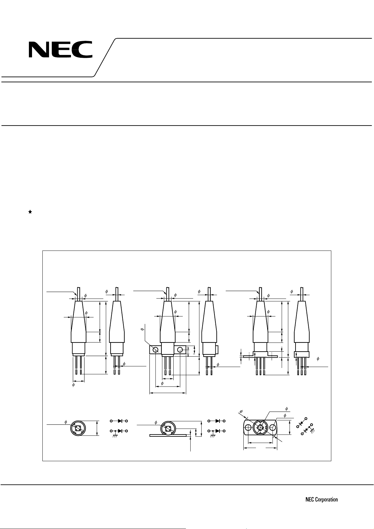
NDL7701P
Optical Fiber
SM-9/125
Length: 1 m
3.2±0.25
6±0.1
PIN CONNECTIONS
P.C.D. = 2
43
2
1
7±0.2
515
20±1.0 27.4±1.0
4
1
7±0.2
φ
Case
0.9
0.45±0.05
PD
LD
Optical Fiber
SM-9/125
Length: 1 m
2.22–
3
P.C.D. = 2
2
PACKAGE DIMENSIONS
in millimeters
NDL7701P1 NDL7701P2
3.2±0.25
7±0.2
6±1.06±1.0
12.7±0.2
17.0±0.2
0.9
515
4.0±0.2
2.0±0.2
20±1.0 27.4±1.0
PIN CONNECTIONS
7.2±0.3
3.7±0.3
1.0±0.1
4
1
Case
43
1
2
Optical Fiber
SM-9/125
Length: 1 m
0.45±0.05
PD
3
2
LD
0.5±0.2
0.3
PIN CONNECTIONS
16
3
12±0.15
16.0
P.C.D. = 2
2
1
4
3.2±0.25
7±0.2
515
2.5±1.0
2– 2.5
0.9
27.7±1.0
0.3
19.5±1.0
PD
3
7±0.2
2
LD
4
4– 0.45
±0.05
1
Case
The information in this document is subject to change without notice.
Document No. P10715EJ4V0DS00 (4th edition)
Date Published November 1998 NS CP(K)
Printed in Japan
The mark
••••
shows major revised points.
©
1995
NDL7701P Series
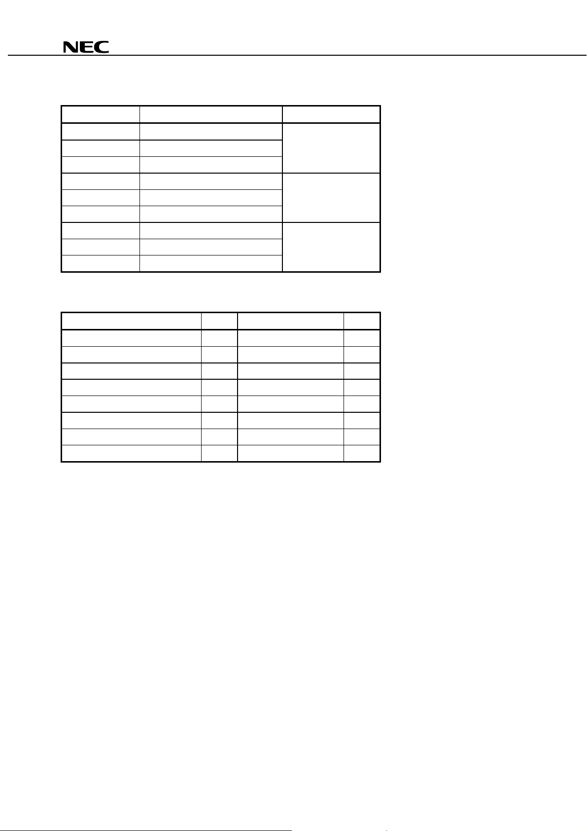
ORDERING INFORMATION
Part Number Available Connector Flange Type
NDL7701P Without Connector No Flange
NDL7701PC With FC-PC Connector
NDL7701PD With SC-PC Connector
NDL7701P1 Without Connector Flat Mount Flange
NDL7701P1C With FC-PC Connector
NDL7701P1D With SC-PC Connector
NDL7701P2 Without Connector Vertical Flange
NDL7701P2C With FC-PC Connector
NDL7701P2D With SC-PC Connector
ABSOLUTE MAXIMUM RATINGS (TC = −−−−20 to +85 °°°°C, unless otherwise specified)
Parameter Symbol Ratings Unit
Optical Output Power from Fiber P
Forward Current of LD I
Reverse Voltage of LD V
Forward Current of PD I
Reverse Voltage of PD V
Operating Case Temperature T
Storage Temperature T
Lead Soldering Temperature (10 s) T
f
F
R
F
R
C
stg
sld
5.0 mW
150 mA
2.0 V
10 mA
20 V
−
20 to +85
−
40 to +85
260
°
C
°
C
°
C
2
NDL7701P Series
η
g
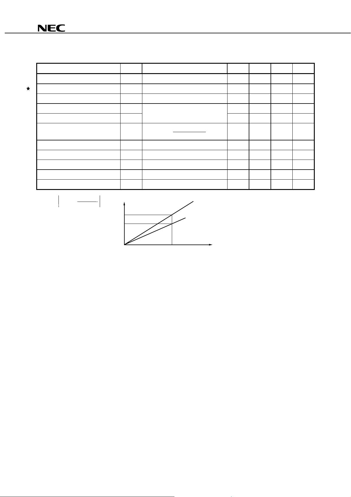
ELECTRO-OPTICAL CHARACTERISTICS (TC = −−−−20 to +85 °°°°C, unless otherwise specified)
Parameter Symbol Conditions MIN. TYP. MAX. Unit
Forward Voltage V
Threshold Current I
Differential Effi c i ency from Fiber
Peak Emission Wavel ength
F
Pf = 2.0 mW, TC = 25 °C1.3V
th
TC = 25 °C1525mA
η
d
Pf = 2.0 mW, TC = 25 °C0.1W/A
λ
p
Pf = 1.0 mW, PN 1/2, Ib = Ith, 1 530 1 550 1 570 nm
Side Mode Suppression Ratio SMSR 622 Mb/s-NRZ 30 dB
η
d
Temperature Dependence of
Differential Effi c i ency from Fiber
Rise Time t
Fall Time t
Monitor Current I
Monitor Dark Current I
Tracking Error
P
γ = 10 log
*1
f
P
2.0 mW
f
(mW)
2.0
f
P
0
∆η
d
∆
d
= 10 lo
r
10-90%, TC = 25 °C0.5ns
f
90-10%, TC = 25 °C0.5ns
m
VR = 5 V, Pf = 2.0 mW 100
D
VR = 5 V, TC = 25 °C0.15nA
*1
γ
Im = const. (@ Pf = 2 mW, TC = 25 °C) 1.0 dB
(@ P
(TC = 85 °C)
η
d
(TC = 25 °C)
TC = 25 ˚C
C
= –20 to +85 ˚C
T
I
m
f
(25 ˚C) = 2.0 mW)
−
3.0
−
2.5 dB
µ
I
m
A
3

NDL7701P Series
DFB-LD FAMILY FOR TELECOM
Absolute Maximum Rat i ngs Typical Characteristics
p
Part Number
T
(°C)
C
stg
T
(°C)
th
I
(mA)
f
P
(mW)
TYP. MIN. TYP.
NDL7603P Series −40 to +85 −40 to +85 15 2 1 310 ≤ STM-4 : 622 Mb/s Coax i al
NDL7620P Series 0 to +70 −40 to +85 45 (MAX.) 2 1 310 ≤ STM-16: 2.5 Gb/s Coaxial
NDL7701P Series −20 to +85 −40 to +85 15 2 1 550 ≤ STM-4 : 622 Mb/s Coax i al
NDL7705P Series −40 to +85 −40 to +85 15 2 1 550 ≤ STM-4 : 622 Mb/s Coax i al
NX8562LB −20 to +65 −40 to +85 20 20
NX8563LB Series −20 to +65 −40 to +85 20 10
NDL7910P −20 to +70 −40 to +85 7 0.5
Wavelength selectable for ITU-T standards upon request.
*1
Wavelength selectable for ITU-T standards.
*2
λ
(nm)
1 550
ITU-T
1 550
SDH Application Package
*1
CW Light Source for
external modulator
*2
CW Light Source for
external modulator
*1
≤ STM-16: 2.5 Gb/s
EA modulator
integrated DFB-LD
BFY
BFY
BFY
4

NDL7701P Series
REFERENCE
Document Name Document No.
NEC semiconductor device reliability/quality control system C11159E
Quality grades on NEC semic onductor devices C11531E
Semiconductor device mounting technology manual C10535E
Semiconductor selection guide X10679E
5

[MEMO]
NDL7701P Series
6

[MEMO]
NDL7701P Series
7

NDL7701P Series
CAUTION
Within this device there exists GaAs (Gallium Arsenide) material which is a
harmful substance if ingested. Please do not under any circumstances break the
hermetic seal.
NEC Corporation
DANGER
INVISIBLE LASER RADIATION
AVOID DIRECT EXPOSURE TO BEAM
OUTPUT POWER mW MAX
WAVELENGTH nm
CLASS lllb LASER PRODUCT
SEMICONDUCTOR LASER
AVOID EXPOSURE-Invisible
Laser Radiation is emitted from
this aperture
The export of this product from Japan is prohibited without governmental license. To export or re-export this product from
a country other than Japan may also be prohibited without a license from that country. Please call an NEC sales
representative.
No part of this document may be copied or reproduced in any form or by any means without the prior written
consent of NEC Corporation. NEC Corporation assumes no responsibility for any errors which may appear in this
document.
NEC Corporation does not assume any liability for infringement of patents, copyrights or other intellectual
property rights of third parties by or arising from use of a device described herein or any other liability arising
from use of such device. No license, either express, implied or otherwise, is granted under any patents,
copyrights or other intellectual property rights of NEC Corporation or others.
While NEC Corporation has been making continuous effort to enhance the reliability of its semiconductor devices,
the possibility of defects cannot be eliminated entirely. To minimize risks of damage or injury to persons or
property arising from a defect in an NEC semiconductor device, customers must incorporate sufficient safety
measures in its design, such as redundancy, fire-containment, and anti-failure features.
NEC devices are classified into the following three quality grades:
"Standard", "Special", and "Specific". The Specific quality grade applies only to devices developed based on
a customer designated "quality assurance program" for a specific application. The recommended applications
of a device depend on its quality grade, as indicated below. Customers must check the quality grade of each
device before using it in a particular application.
Standard: Computers, office equipment, communications equipment, test and measurement equipment,
audio and visual equipment, home electronic appliances, machine tools, personal electronic
equipment and industrial robots
Special: Transportation equipment (automobiles, trains, ships, etc.), traffic control systems, anti-disaster
systems, anti-crime systems, safety equipment and medical equipment (not specifically designed
for life support)
Specific: Aircrafts, aerospace equipment, submersible repeaters, nuclear reactor control systems, life
support systems or medical equipment for life support, etc.
The quality grade of NEC devices is "Standard" unless otherwise specified in NEC's Data Sheets or Data Books.
If customers intend to use NEC devices for applications other than those specified for Standard quality grade,
they should contact an NEC sales representative in advance.
Anti-radioactive design is not implemented in this product.
NEC Building, 7-1, Shiba 5-chome,
Minato-ku, Tokyo 108-01, Japan
Type number:
Manufactured:
Serial Number:
This product conforms to FDA
regulations as applicable
to standards 21 CFR Chapter 1.
Subchapter J.
M4 96. 5
 Loading...