

Page 1

NDA-24305
ISSUE 1
STOCK # 2 00813
®
ISDN Feature Programming Manual
OCTOBER, 2000
NEC America, Inc.
Page 2

Page 3

LIABILITY DISCLAIMER
NEC America, Inc. reserves the right to change the specifications, functions, or
features, at any time, without notice.
NEC America, Inc. has prepared this document for use by its employees and
custom ers. Th e info rma tion co ntai ne d here in is the prop erty of NEC America ,
Inc. and shall not be reproduced without prior written approval from NEC
Americ a, In c .
NEAX
®
and D
term®
are registered trademarks of NEC Corporation.
Copy right 2000
NEC America, Inc.
Printed in the U.S.A
Page 4

Page 5

PAGE No.
i 1
ii 1
iii 1
iv
v 1
vi 1
vii 1
viii
1 1
2 1
3 1
4
5 1
6 1
7 1
8
9 1
10 1
11 1
12
13 1
14 1
15 1
16
17 1
18 1
19 1
20
21 1
22 1
23 1
24
25 1
26 1
27 1
28
29 1
30 1
DATE OCTOBER, 2000 DA TE DATE DATE
DATE DATE DATE DATE
12345678
1
1
1
1
1
1
1
1
1
ISSUE 1 ISSUE 2 ISSUE 3 ISSUE 4
ISSUE 5 ISSUE 6 ISSUE 7 ISSUE 8
ISSUE No.
PAGE No.
31 1
32
33 1
34 1
35 1
36
37 1
38 1
39 1
40
41 1
42 1
43 1
44
45 1
46 1
47 1
48
49 1
50 1
51 1
52
53 1
54 1
55 1
56
57 1
58 1
59 1
60
61 1
62 1
63 1
64
65 1
66 1
67 1
68
12345678
1
1
1
1
1
1
1
1
1
1
ISSUE No.
NEAX2400 IPX
ISDN Feature Programming Manual
Revisi on S heet 1/5
NDA-24305
Page 6

PAGE No.
69 1
70 1
71 1
72
73 1
74 1
75 1
76
77 1
78 1
79 1
80
81 1
82 1
83 1
84
85 1
86 1
87 1
88
89 1
90 1
91 1
92
93 1
94 1
95 1
96
97 1
98 1
99 1
100
101 1
102 1
103 1
104
105 1
106 1
DATE OCTOBER, 2000 DA TE DATE DATE
DATE DATE DATE DATE
12345678
1
1
1
1
1
1
1
1
1
ISSUE 1 ISSUE 2 ISSUE 3 ISSUE 4
ISSUE 5 ISSUE 6 ISSUE 7 ISSUE 8
ISSUE No.
PAGE No.
107 1
108
109 1
110 1
111 1
112
113 1
114 1
115 1
116
117 1
118 1
119 1
120
121 1
122 1
123 1
124
125 1
126 1
127 1
128
129 1
130 1
131 1
132
133 1
134 1
135 1
136
137 1
138 1
139 1
140
141 1
142 1
143 1
144
12345678
1
1
1
1
1
1
1
1
1
1
ISSUE No.
NEAX2400 IPX
ISDN Feature Programming Manual
Revisi on S heet 2/5
NDA-24305
Page 7

PAGE No.
145 1
146 1
147 1
148
149 1
150 1
151 1
152
153 1
154 1
155 1
156
157 1
158 1
159 1
160
161 1
162 1
163 1
164
165 1
166 1
167 1
168
169 1
170 1
171 1
172
173 1
174 1
175 1
176
177 1
178 1
179 1
180
181 1
182 1
DATE OCTOBER, 2000 DA TE DATE DATE
DATE DATE DATE DATE
12345678
1
1
1
1
1
1
1
1
1
ISSUE 1 ISSUE 2 ISSUE 3 ISSUE 4
ISSUE 5 ISSUE 6 ISSUE 7 ISSUE 8
ISSUE No.
PAGE No.
183 1
184
185 1
186 1
187 1
188
189 1
190 1
191 1
192
193 1
194 1
195 1
196
197 1
198 1
199 1
200
201 1
202 1
203 1
204
205 1
206 1
207 1
208
209 1
210 1
211 1
212
213 1
214 1
215 1
216
217 1
218 1
219 1
220
12345678
1
1
1
1
1
1
1
1
1
1
ISSUE No.
NEAX2400 IPX
ISDN Feature Programming Manual
Revisi on S heet 3/5
NDA-24305
Page 8

PAGE No.
221 1
222 1
223 1
224
225 1
226 1
227 1
228
229 1
230 1
231 1
232
233 1
234 1
235 1
236
237 1
238 1
239 1
240
241 1
242 1
243 1
244
245 1
246 1
247 1
248
249 1
250 1
251 1
252
253 1
254 1
255 1
256
257 1
258 1
DATE OCTOBER, 2000 DA TE DATE DATE
DATE DATE DATE DATE
12345678
1
1
1
1
1
1
1
1
1
ISSUE 1 ISSUE 2 ISSUE 3 ISSUE 4
ISSUE 5 ISSUE 6 ISSUE 7 ISSUE 8
ISSUE No.
PAGE No.
259 1
260
261 1
262 1
263 1
264
265 1
266 1
267 1
268
269 1
270 1
271 1
272
273 1
274 1
275 1
276
277 1
278 1
279 1
280
281 1
282 1
283 1
284
285 1
286 1
287 1
288
289 1
290 1
291 1
292
293 1
294 1
295 1
296
12345678
1
1
1
1
1
1
1
1
1
1
ISSUE No.
NEAX2400 IPX
ISDN Feature Programming Manual
Revisi on S heet 4/5
NDA-24305
Page 9

PAGE No.
297 1
298 1
ISSUE No.
12345678
PAGE No.
ISSUE No.
12345678
ISSUE 1 ISSUE 2 ISSUE 3 ISSUE 4
DATE OCTOBER, 2000 DA TE DATE DATE
ISSUE 5 ISSUE 6 ISSUE 7 ISSUE 8
DATE DATE DATE DATE
NEAX2400 IPX
ISDN Feature Programming Manual
Revisi on S heet 5/5
NDA-24305
Page 10

Page 11

NDA-24305
ISSUE 1
OCTOBER, 2000
NEAX2400 IPX
ISDN Feature Programming Manual
TABLE OF CONTENTS
Page
LIST OF FIGURES . . . . . . . . . . . . . . . . . . . . . . . . . . . . . . . . . . . . . . . . . . . . . . . . . . . . . . . . . . . . . . . . . . . . . . . . v
LIST OF TABLES. . . . . . . . . . . . . . . . . . . . . . . . . . . . . . . . . . . . . . . . . . . . . . . . . . . . . . . . . . . . . . . . . . . . . . . . . vii
CHAPTER 1 INTRODUCTION . . . . . . . . . . . . . . . . . . . . . . . . . . . . . . . . . . . . . . . . . . . . . . . . . . . . . . . . . . . . . 1
1. GENERAL. . . . . . . . . . . . . . . . . . . . . . . . . . . . . . . . . . . . . . . . . . . . . . . . . . . . . . . . . . 1
2. HOW TO FOLLOW THE MANUAL . . . . . . . . . . . . . . . . . . . . . . . . . . . . . . . . . . . . . . . . . . 1
2.1 CONFIGURATION OF THIS MANUAL . . . . . . . . . . . . . . . . . . . . . . . . . . . . . . . . . . . . . . . . . . . 1
CHAPTER 2 GENERAL INFORMATION . . . . . . . . . . . . . . . . . . . . . . . . . . . . . . . . . . . . . . . . . . . . . . . . . . . . . 3
1. GENERAL. . . . . . . . . . . . . . . . . . . . . . . . . . . . . . . . . . . . . . . . . . . . . . . . . . . . . . . . . . 3
2. HARDWARE CONFIGURATION. . . . . . . . . . . . . . . . . . . . . . . . . . . . . . . . . . . . . . . . . . . . 3
3. BASIC KNOWLEDGE . . . . . . . . . . . . . . . . . . . . . . . . . . . . . . . . . . . . . . . . . . . . . . . . . . 4
3.1 MESSAGE SEQUENCES FOR LAYER 3 . . . . . . . . . . . . . . . . . . . . . . . . . . . . . . . . . . . . . . . . . 4
3.2 BEARER CAPABILITY (BC) INFORMATION ELEMENT . . . . . . . . . . . . . . . . . . . . . . . . . . . . . 5
CHAPTER 3 BASIC DATA ASSIGNMENT FOR ISDN . . . . . . . . . . . . . . . . . . . . . . . . . . . . . . . . . . . . . . . . . . . 7
1. ISDN LINE ACCESS CODE ASSIGNMENT . . . . . . . . . . . . . . . . . . . . . . . . . . . . . . . . . . . . 7
2. ISDN TRUNK DATA ASSIGNMENT. . . . . . . . . . . . . . . . . . . . . . . . . . . . . . . . . . . . . . . . . . 9
3. CALLING NUMBER PATTERN DATA (CNP) ASSIGNMENT . . . . . . . . . . . . . . . . . . . . . . . . . 15
CHAPTER 4 COMMANDS CONCERNING ISDN DATA ASSIGNMENT . . . . . . . . . . . . . . . . . . . . . . . . . . . .17
1. GENERAL. . . . . . . . . . . . . . . . . . . . . . . . . . . . . . . . . . . . . . . . . . . . . . . . . . . . . . . . . 17
2. COMMANDS . . . . . . . . . . . . . . . . . . . . . . . . . . . . . . . . . . . . . . . . . . . . . . . . . . . . . . . 18
2.1 ASYD: ASSIGNMENT OF SYSTEM DATA. . . . . . . . . . . . . . . . . . . . . . . . . . . . . . . . . . . . . . . 18
2.2 ASFC: ASSIGNMENT OF SERVICE FEATURE CLASS DATA. . . . . . . . . . . . . . . . . . . . . . . 21
2.3 ARTD: ASSIGNMENT OF ROUTE CLASS DATA . . . . . . . . . . . . . . . . . . . . . . . . . . . . . . . . . 21
2.4 ARTI: ASSIGNMENT OF TRUNK APPLICATION DATA . . . . . . . . . . . . . . . . . . . . . . . . . . . 22
CHAPTER 5 GATEWAY SERVICE . . . . . . . . . . . . . . . . . . . . . . . . . . . . . . . . . . . . . . . . . . . . . . . . . . . . . . . . 27
A-76 ALTERNATE ROUTING-PRI. . . . . . . . . . . . . . . . . . . . . . . . . . . . . . . . . . . . . . . . . . . . . . . 31
A-88 AUTOMATIC CALL DISTRIBUTION-PRI . . . . . . . . . . . . . . . . . . . . . . . . . . . . . . . . . . . . . 32
A-92 ANNOUNCEMENT SERVICE-PRI . . . . . . . . . . . . . . . . . . . . . . . . . . . . . . . . . . . . . . . . . . 34
A-94 AUTOMATIC CIRCUIT ASSURANCE-PRI. . . . . . . . . . . . . . . . . . . . . . . . . . . . . . . . . . . . 35
A-96 AUTOMATIC TRUNK TEST-PRI. . . . . . . . . . . . . . . . . . . . . . . . . . . . . . . . . . . . . . . . . . . . 36
B-19 BOSS-SECRETARY TRANSFER-PRI . . . . . . . . . . . . . . . . . . . . . . . . . . . . . . . . . . . . . . . 37
B-22 BOSS-SECRETARY OVERRIDE-PRI . . . . . . . . . . . . . . . . . . . . . . . . . . . . . . . . . . . . . . . 38
C-95 CALL FORWARDING-ALL CALLS-P RI . . . . . . . . . . . . . . . . . . . . . . . . . . . . . . . . . . . . . . 40
C-95D CALL FORWARDING-ALL CALLS-D
C-96 CALL FORWARDING-BUSY LINE-PRI . . . . . . . . . . . . . . . . . . . . . . . . . . . . . . . . . . . . . . 45
C-97 CALL PICKUP-GROUP-PRI . . . . . . . . . . . . . . . . . . . . . . . . . . . . . . . . . . . . . . . . . . . . . . . 47
term
-PRI. . . . . . . . . . . . . . . . . . . . . . . . . . . . . . . . . . 42
NDA-24305 TABLE OF CONTENTS
Page i
Revision 1.0
Page 12

TABLE OF CONTENTS (CONTINUED)
Page
C-97D CALL PICKUP-GROUP-D
C-98 CALL TRANSFER-ATTENDANT-PRI . . . . . . . . . . . . . . . . . . . . . . . . . . . . . . . . . . . . . . . . 49
C-99 CALL TRANSFER-ALL CALLS-PRI . . . . . . . . . . . . . . . . . . . . . . . . . . . . . . . . . . . . . . . . . . 50
C-99D CALL TRANSFER-ALL CALLS-D
C-100 CONSULTATION HOLD-ALL CALLS-PRI. . . . . . . . . . . . . . . . . . . . . . . . . . . . . . . . . . . . . 52
C-100D CONSULTATION HOLD-ALL CALLS-D
C-101 CALL FORWARDING-INTERCEPT/ANNOUNCEMENT-PRI . . . . . . . . . . . . . . . . . . . . . . 54
C-102 CALL PICKUP-DIRECT-PRI. . . . . . . . . . . . . . . . . . . . . . . . . . . . . . . . . . . . . . . . . . . . . . . . 56
C-114 CALL WAITING-TERMINATING-PRI . . . . . . . . . . . . . . . . . . . . . . . . . . . . . . . . . . . . . . . . . 57
C-119 CALL PARK-PRI. . . . . . . . . . . . . . . . . . . . . . . . . . . . . . . . . . . . . . . . . . . . . . . . . . . . . . . . . 58
C-123 CALL FORWARDING-ALL CALLS-ANNOUNCEMENT-PRI . . . . . . . . . . . . . . . . . . . . . . . 60
C-125 CALL FORWARDING-INTERCEPT-PRI . . . . . . . . . . . . . . . . . . . . . . . . . . . . . . . . . . . . . . 63
C-129 CALL FORWARDING-DON’T ANSWER-PRI. . . . . . . . . . . . . . . . . . . . . . . . . . . . . . . . . . . 64
D-115 DISTINCTIVE RINGING-PRI . . . . . . . . . . . . . . . . . . . . . . . . . . . . . . . . . . . . . . . . . . . . . . . 66
D-116D DO NOT DISTURB-D
D-117 DATA LINE SECURITY-PRI. . . . . . . . . . . . . . . . . . . . . . . . . . . . . . . . . . . . . . . . . . . . . . . . 68
D-118 DATA PRIVACY ON DEMAND-PRI . . . . . . . . . . . . . . . . . . . . . . . . . . . . . . . . . . . . . . . . . . 69
D-119 DATA INTERFACE-AUTOMATIC ANSWER-PRI . . . . . . . . . . . . . . . . . . . . . . . . . . . . . . . 70
D-120 DATA TRANSPARENCY-PRI . . . . . . . . . . . . . . . . . . . . . . . . . . . . . . . . . . . . . . . . . . . . . . 71
D-121 DATA COMMUNICATIONS-PRI . . . . . . . . . . . . . . . . . . . . . . . . . . . . . . . . . . . . . . . . . . . . 72
D-122 DATA UNIFORM NUMBERING PLAN-PRI . . . . . . . . . . . . . . . . . . . . . . . . . . . . . . . . . . . . 76
D-137 DIRECT-IN TERMINATION (DIT)-PRI . . . . . . . . . . . . . . . . . . . . . . . . . . . . . . . . . . . . . . . . 78
E-14D ELAPSED TIME DISPLAY-D
F-21 FLEXIBLE NUMBERING OF STATIONS-PRI . . . . . . . . . . . . . . . . . . . . . . . . . . . . . . . . . . 81
F-26 FAULTY TRUNK REPORT-PRI . . . . . . . . . . . . . . . . . . . . . . . . . . . . . . . . . . . . . . . . . . . . . 82
H-14D HANDS-FREE ANSWER BACK-D
H-15 HOT LINE-OUTSIDE-PRI. . . . . . . . . . . . . . . . . . . . . . . . . . . . . . . . . . . . . . . . . . . . . . . . . . 84
I-24 INCOMING CALL IDENTIFICATION-PRI. . . . . . . . . . . . . . . . . . . . . . . . . . . . . . . . . . . . . . 86
I-25 INCOMING ISDN CALL TO TIE LINE CONNECTION-PRI . . . . . . . . . . . . . . . . . . . . . . . . 88
I-26 INDIALING THROUGH MAIN-PRI . . . . . . . . . . . . . . . . . . . . . . . . . . . . . . . . . . . . . . . . . . . 90
I-27 INTER-PBX COORDINATED STATION NUMBERING PLAN-PRI . . . . . . . . . . . . . . . . . . 92
I-28 ISDN INDIVIDUAL CALLING LINE IDENTIFICATION (ICLID) . . . . . . . . . . . . . . . . . . . . . 93
I-36 INTER-OFFICE OFF-HOOK QUEUING-PRI . . . . . . . . . . . . . . . . . . . . . . . . . . . . . . . . . . . 94
L-31 LEAST COST ROUTING-3/6-DIGIT-PRI . . . . . . . . . . . . . . . . . . . . . . . . . . . . . . . . . . . . . . 96
L-32 LCR-TIME OF DAY ROUTING-PRI . . . . . . . . . . . . . . . . . . . . . . . . . . . . . . . . . . . . . . . . . . 99
L-33 LCR-ATTENDANT MANUAL OVERRIDE-PRI. . . . . . . . . . . . . . . . . . . . . . . . . . . . . . . . . 100
L-34 LCR-AUTOMATIC OVERFLOW TO DDD-PRI. . . . . . . . . . . . . . . . . . . . . . . . . . . . . . . . . 101
L-35 LCR-CLOCKED MANUAL OVERRIDE-PRI. . . . . . . . . . . . . . . . . . . . . . . . . . . . . . . . . . . 102
L-42 LAST NUMBER CALL-PRI. . . . . . . . . . . . . . . . . . . . . . . . . . . . . . . . . . . . . . . . . . . . . . . . 103
L-42D LAST NUMBER CALLED-D
L-44 LDN NIGHT CONNECTION-PRI . . . . . . . . . . . . . . . . . . . . . . . . . . . . . . . . . . . . . . . . . . . 106
L-46 LDN NIGHT CONNECTION-OUTSIDE-PRI. . . . . . . . . . . . . . . . . . . . . . . . . . . . . . . . . . . 107
L-49 LCR-SPECIAL LINE WARNING TONE-PRI. . . . . . . . . . . . . . . . . . . . . . . . . . . . . . . . . . . 108
M-71 MISCELLANEOUS TRUNK ACCESS-PRI. . . . . . . . . . . . . . . . . . . . . . . . . . . . . . . . . . . . 109
M-72 MISCELLANEOUS TRUNK RESTRICTION-PRI . . . . . . . . . . . . . . . . . . . . . . . . . . . . . . . 110
M-73 MUSIC ON HOLD-PRI . . . . . . . . . . . . . . . . . . . . . . . . . . . . . . . . . . . . . . . . . . . . . . . . . . . 111
M-74 MODEM POOLING-PRI . . . . . . . . . . . . . . . . . . . . . . . . . . . . . . . . . . . . . . . . . . . . . . . . . . 112
M-75 MULTIPLE CALL FORWARDING-ALL CALLS-PRI. . . . . . . . . . . . . . . . . . . . . . . . . . . . . 114
N-20 NIGHT CONNECTION-FIXED-PRI . . . . . . . . . . . . . . . . . . . . . . . . . . . . . . . . . . . . . . . . . 116
N-21 NIGHT CONNECTION-FLEXIBLE-PRI . . . . . . . . . . . . . . . . . . . . . . . . . . . . . . . . . . . . . . 117
term
-PRI . . . . . . . . . . . . . . . . . . . . . . . . . . . . . . . . . . . . . . . . . . . 48
term
-PRI . . . . . . . . . . . . . . . . . . . . . . . . . . . . . . . . . . . . . 51
term
-PRI . . . . . . . . . . . . . . . . . . . . . . . . . . . . . . . . 53
term
-PRI . . . . . . . . . . . . . . . . . . . . . . . . . . . . . . . . . . . . . . . . . . . . . . 67
term
-PRI. . . . . . . . . . . . . . . . . . . . . . . . . . . . . . . . . . . . . . . . . 80
term
-PRI . . . . . . . . . . . . . . . . . . . . . . . . . . . . . . . . . . . . 83
term
-PRI . . . . . . . . . . . . . . . . . . . . . . . . . . . . . . . . . . . . . . . . 104
TABLE OF CONTENTS NDA-24305
Page i i
Revision 1.0
Page 13

TABLE OF CONTENTS (CONTINUED)
Page
N-22 NON-DELAY OPERATION-PRI . . . . . . . . . . . . . . . . . . . . . . . . . . . . . . . . . . . . . . . . . . . . 118
N-29 NIGHT CONNECTION OUTSIDE-SYSTEM-PRI. . . . . . . . . . . . . . . . . . . . . . . . . . . . . . . 119
N-31 NAILED DOWN CONNECTION-PRI . . . . . . . . . . . . . . . . . . . . . . . . . . . . . . . . . . . . . . . . 120
O-24 OUTGOING TRUNK QUEUING-PRI . . . . . . . . . . . . . . . . . . . . . . . . . . . . . . . . . . . . . . . . 121
O-26 OUTGOING TRUNK QUEUING-DELUXE-PRI . . . . . . . . . . . . . . . . . . . . . . . . . . . . . . . . 123
O-28 OFF-HOOK QUEUING-PRI . . . . . . . . . . . . . . . . . . . . . . . . . . . . . . . . . . . . . . . . . . . . . . . 125
O-30 OUTGOING TRUNK QUEUING-ATTENDANT-PRI. . . . . . . . . . . . . . . . . . . . . . . . . . . . . 126
O-32 OVERFLOW-UCD-PRI. . . . . . . . . . . . . . . . . . . . . . . . . . . . . . . . . . . . . . . . . . . . . . . . . . . 127
P-37 PEG COUNT-PRI. . . . . . . . . . . . . . . . . . . . . . . . . . . . . . . . . . . . . . . . . . . . . . . . . . . . . . . 129
P-38 PRIMARY CALL RESTRICTION-PRI. . . . . . . . . . . . . . . . . . . . . . . . . . . . . . . . . . . . . . . . 130
P-39 PRI TRUNK TO TIE LINE CONNECTION WITH PAD CONTROL . . . . . . . . . . . . . . . . . 131
P-47 PAGING TRANSFER-PRI . . . . . . . . . . . . . . . . . . . . . . . . . . . . . . . . . . . . . . . . . . . . . . . . 132
P-49 PRI FAILSAFE ROUTING . . . . . . . . . . . . . . . . . . . . . . . . . . . . . . . . . . . . . . . . . . . . . . . . 134
R-35 RESTRICTION FROM OUTGOING CALLS-PRI . . . . . . . . . . . . . . . . . . . . . . . . . . . . . . . 135
S-82 SPEED CALLING-SYSTEM-PRI . . . . . . . . . . . . . . . . . . . . . . . . . . . . . . . . . . . . . . . . . . . 136
S-82D SPEED CALLING-SYSTEM-D
S-83 STATION MESSAGE DETAIL RECORDING SYSTEM-RS232C-PRI. . . . . . . . . . . . . . . 139
S-84 SPEED CALLING-STATION-PRI . . . . . . . . . . . . . . . . . . . . . . . . . . . . . . . . . . . . . . . . . . . 142
S-85 SPEED CALLING-GROUP-PRI . . . . . . . . . . . . . . . . . . . . . . . . . . . . . . . . . . . . . . . . . . . . 143
S-86 SIMULTANEOUS VOICE AND DATA TRANSMISSION-PRI . . . . . . . . . . . . . . . . . . . . . 144
S-87 SYNCHRONOUS DATA SWITCHING-PRI . . . . . . . . . . . . . . . . . . . . . . . . . . . . . . . . . . . 147
S-88 SMDR FOR DATA CALL-RS232C-PRI . . . . . . . . . . . . . . . . . . . . . . . . . . . . . . . . . . . . . . 148
S-89 SPEED CALLING OVERRIDE-SYSTEM-PRI . . . . . . . . . . . . . . . . . . . . . . . . . . . . . . . . . 149
S-107 STATION INDIVIDUAL TRUNK ACCESS-PRI. . . . . . . . . . . . . . . . . . . . . . . . . . . . . . . . . 150
T-37 TANDEM SWITCHI N G OF TI E TRUNKS-2/4-WIRE-PRI. . . . . . . . . . . . . . . . . . . . . . . . . 151
T-38 THREE-WAY CALLING-PRI. . . . . . . . . . . . . . . . . . . . . . . . . . . . . . . . . . . . . . . . . . . . . . . 153
T-38D THREE-WAY CALLING- D
T-40 TOLL DENIAL/TOLL DIVERSION-PRI. . . . . . . . . . . . . . . . . . . . . . . . . . . . . . . . . . . . . . . 155
T-41 TOLL RESTRICTION-3/6-DIGIT-PRI. . . . . . . . . . . . . . . . . . . . . . . . . . . . . . . . . . . . . . . . 156
U-6 UNIFORM CALL DISTRIBUTION (UCD)-PRI . . . . . . . . . . . . . . . . . . . . . . . . . . . . . . . . . 158
term
-PRI . . . . . . . . . . . . . . . . . . . . . . . . . . . . . . . . . . . . . . 137
term
-PRI. . . . . . . . . . . . . . . . . . . . . . . . . . . . . . . . . . . . . . . . . . 154
CHAPTER 6 SUPPLEMENTARY SERVICE . . . . . . . . . . . . . . . . . . . . . . . . . . . . . . . . . . . . . . . . . . . . . . . . 161
1. ISDN TERMINAL (5 ESS). . . . . . . . . . . . . . . . . . . . . . . . . . . . . . . . . . . . . . . . . . . . . . . 163
2. ISDN TERMINAL (NATIONAL ISDN1) . . . . . . . . . . . . . . . . . . . . . . . . . . . . . . . . . . . . . . . 163
3. PRI STATION (H0) . . . . . . . . . . . . . . . . . . . . . . . . . . . . . . . . . . . . . . . . . . . . . . . . . . . 165
4. PRI STATION (H11) . . . . . . . . . . . . . . . . . . . . . . . . . . . . . . . . . . . . . . . . . . . . . . . . . . 167
C-103 CALLING PARTY RECOGNITION SERVICE
(CALL FORWARDING-ALL CALLS/BUSY LINE/DON’T ANSWER) . . . . . . . . . . . . . . . . 169
C-104 CALLING PARTY RECOGNITION SERVICE [DIRECT-IN TERMINATION (DIT)] . . . . . 172
C-170 CALL REDIRECTION (FOR AT&T #4ESS) . . . . . . . . . . . . . . . . . . . . . . . . . . . . . . . . . . . 175
D-123 DID ADDRESSING. . . . . . . . . . . . . . . . . . . . . . . . . . . . . . . . . . . . . . . . . . . . . . . . . . . . . . 176
N-47 NETWORK NAME DISPLAY (NI-2 PRI). . . . . . . . . . . . . . . . . . . . . . . . . . . . . . . . . . . . . . 178
S-93 SID TO TERMINATING USER - DISPLAY. . . . . . . . . . . . . . . . . . . . . . . . . . . . . . . . . . . . 180
S-136 SID TO TERMINATING USER (CALL-BY-CALL) - DISPLAY FOR AT&T (#4ESS). . . . . 181
S-94 SID TO TERMINATING USER - DTE. . . . . . . . . . . . . . . . . . . . . . . . . . . . . . . . . . . . . . . . 182
S-95 SUB ADDRESS - ADDRESSING. . . . . . . . . . . . . . . . . . . . . . . . . . . . . . . . . . . . . . . . . . . 183
A-77 ACCUNET ACCESS154. . . . . . . . . . . . . . . . . . . . . . . . . . . . . . . . . . . . . . . . . . . . . . . . . . 184
B-27 B-CHANNEL SERVICE CONTROL . . . . . . . . . . . . . . . . . . . . . . . . . . . . . . . . . . . . . . . . . 185
C-106 CALL-BY-CALL POOL MANAGEMENT. . . . . . . . . . . . . . . . . . . . . . . . . . . . . . . . . . . . . . 186
C-105 CALL-BY-CALL SERVICE SELECTION . . . . . . . . . . . . . . . . . . . . . . . . . . . . . . . . . . . . . 187
NDA-24305 TABLE OF CONTENTS
Page iii
Revision 1.0
Page 14

TABLE OF CONTENTS (CONTINUED)
Page
C-164 CCIS TANDEM CALL-CALLING PARTY NUMBER (CPN) DELIVERY TO ISDN & Q-SIG
NETWORKS. . . . . . . . . . . . . . . . . . . . . . . . . . . . . . . . . . . . . . . . . . . . . . . . . . . . . . . . . . . 188
D-152 D-CHANNEL BACKUP - PRI . . . . . . . . . . . . . . . . . . . . . . . . . . . . . . . . . . . . . . . . . . . . . . 191
M-76 MEGACOM ACCESS. . . . . . . . . . . . . . . . . . . . . . . . . . . . . . . . . . . . . . . . . . . . . . . . . . . . 194
M-77 MEGACOM800 SERVICE . . . . . . . . . . . . . . . . . . . . . . . . . . . . . . . . . . . . . . . . . . . . . . . . 195
N-40 NON-FACILITY ASSOCIATED SIGNALING - PRI. . . . . . . . . . . . . . . . . . . . . . . . . . . . . . 196
Q-5 Q-SIG/ISDN INTERNATIONAL GATEWAY SWITCHING . . . . . . . . . . . . . . . . . . . . . . . . 200
S-90 SDN ACCESS . . . . . . . . . . . . . . . . . . . . . . . . . . . . . . . . . . . . . . . . . . . . . . . . . . . . . . . . . 204
S-91/S-92 SID TO NETWORK - PRE SENT/SID TO NETWORK - PRIVACY. . . . . . . . . . . . . . . . . . 205
S-96 SUB ADDRESS - PRESENT . . . . . . . . . . . . . . . . . . . . . . . . . . . . . . . . . . . . . . . . . . . . . . 207
T-42 TRUNK PROVISIONING SERVIC E SELECTION . . . . . . . . . . . . . . . . . . . . . . . . . . . . . . 208
W-9 WIDE BAND SWITCHING FOR AT&T #4ESS. . . . . . . . . . . . . . . . . . . . . . . . . . . . . . . . . 209
C-112/T-44 CALLING PARTY INFORMATION TRANSFER/TRANSFER MESSAGE (TRM) . . . . . . 210
N-42 NATIONAL - ISDN2 - PRI. . . . . . . . . . . . . . . . . . . . . . . . . . . . . . . . . . . . . . . . . . . . . . . . . 213
V-18 VIRTUAL TIE LINE. . . . . . . . . . . . . . . . . . . . . . . . . . . . . . . . . . . . . . . . . . . . . . . . . . . . . . 214
E-23 EVENT BASED CCIS - ISDN TRANSPORT . . . . . . . . . . . . . . . . . . . . . . . . . . . . . . . . . . 219
E-24 EVENT BASED CCIS - Q-SIG TRANSPORT . . . . . . . . . . . . . . . . . . . . . . . . . . . . . . . . . 231
C-152 CALL COMPL ETION O N NO REPLY (CCNR). . . . . . . . . . . . . . . . . . . . . . . . . . . . . . . . . 240
C-148 CALL COMPLETION TO BUSY SUBSCRIBER (CCBS) . . . . . . . . . . . . . . . . . . . . . . . . . 246
C-153 CNIP/CONP . . . . . . . . . . . . . . . . . . . . . . . . . . . . . . . . . . . . . . . . . . . . . . . . . . . . . . . . . . . 254
C-158 CALL FORWARDIN G S UPPLEMENTARY SERVICE (SS-CF) WITH REROUTING . . . 257
C-159 CALL TRANSFER SUPPLEMENTARY SERVICE (SS-CT) WITH REROUTING . . . . . . 270
I-42 IS-11572 (LAYER 3 SPECIFICATIONS FOR INTER-PBX SIGNAL ING PROTOCOL) . . 277
Q-4 Q-SIG (CIRCUIT SWITCHED BASIC CALL - ETSI VERSION) . . . . . . . . . . . . . . . . . . . . 285
A-136 ADVICE OF CHARGE (AOC) - RECEIPT AND DISPLAY OF AOC FROM A FOREIGN Q-SIG
NETWORK . . . . . . . . . . . . . . . . . . . . . . . . . . . . . . . . . . . . . . . . . . . . . . . . . . . . . . . . . . . . 294
TABLE OF CONTENTS NDA-24305
Page i v
Revision 1.0
Page 15

LIST OF FIGURES
Figure Title Page
Figure 2-1 Hardware Configuration . . . . . . . . . . . . . . . . . . . . . . . . . . . . . . . . . . . . . . . . . . . . . . . . . . . . 3
Figure 2-2 Message Sequences for Layer3 . . . . . . . . . . . . . . . . . . . . . . . . . . . . . . . . . . . . . . . . . . . . . . 4
Figure 3-1 ATRK for 24PRT . . . . . . . . . . . . . . . . . . . . . . . . . . . . . . . . . . . . . . . . . . . . . . . . . . . . . . . . . 11
Figure 3-2 ATRK for 24DTR + 2DCH . . . . . . . . . . . . . . . . . . . . . . . . . . . . . . . . . . . . . . . . . . . . . . . . . . 12
Figure 3-3 Calling Number When Interworking with FCCS Link . . . . . . . . . . . . . . . . . . . . . . . . . . . . . 15
Figure 5-1 Typical Modem-to-Modem Connection . . . . . . . . . . . . . . . . . . . . . . . . . . . . . . . . . . . . . . . . 72
Figure 5-2 Modem Pool to Modem Pool . . . . . . . . . . . . . . . . . . . . . . . . . . . . . . . . . . . . . . . . . . . . . . . . 73
Figure 5-3 Asynchronous DTE Connected to a Data Module . . . . . . . . . . . . . . . . . . . . . . . . . . . . . . . 74
Figure 5-4 Example of SMDR Assignments . . . . . . . . . . . . . . . . . . . . . . . . . . . . . . . . . . . . . . . . . . . . 141
Figure 6-1 Assigning Transfer Destination . . . . . . . . . . . . . . . . . . . . . . . . . . . . . . . . . . . . . . . . . . . . . 174
Figure 6-2 Example of a Call Originated through CCIS Line to Corresponding ISDN Network . . . . . 189
Figure 6-1 Connection Patterns for UUS Transmission . . . . . . . . . . . . . . . . . . . . . . . . . . . . . . . . . . . 291
NDA-24305 LIST OF FIGURES
Page v
Revision 1.0
Page 16

This page is for your notes.
LIST OF FIGURES NDA-24305
Page vi
Revision 1.0
Page 17

LIST OF TABLES
Table Title Page
Table 2-1 Hardware . . . . . . . . . . . . . . . . . . . . . . . . . . . . . . . . . . . . . . . . . . . . . . . . . . . . . . . . . . . . . . . 3
Table 5-1 Gateway Service List . . . . . . . . . . . . . . . . . . . . . . . . . . . . . . . . . . . . . . . . . . . . . . . . . . . . . 27
Table 5-1 ACD Features . . . . . . . . . . . . . . . . . . . . . . . . . . . . . . . . . . . . . . . . . . . . . . . . . . . . . . . . . . 32
Table 6-1 ISDN Station . . . . . . . . . . . . . . . . . . . . . . . . . . . . . . . . . . . . . . . . . . . . . . . . . . . . . . . . . . 161
Table 6-2 Supplementary Service List. . . . . . . . . . . . . . . . . . . . . . . . . . . . . . . . . . . . . . . . . . . . . . . 161
Table 5-1 Reference: Output Layer 1 Protocol. . . . . . . . . . . . . . . . . . . . . . . . . . . . . . . . . . . . . . . . . 202
Table 6-1 Transparency of Bearer Capability When Interworking with C.O./Tie Line. . . . . . . . . . . . 278
NDA-24305 LIST OF TABLES
Page v ii
Revision 1.0
Page 18

This page is for your notes.
LIST OF TABLES NDA-24305
Page viii
Revision 1.0
Page 19

CHAPTER 1 INTRODUCTION
1. GENERAL
The ISDN System Data Design Manual provides general information for ISDN, office data design for ISDN,
and ISDN se rv i ce.
2. HOW TO FOLLOW THE MANUAL
2.1 CONFIGURATION OF THIS MANUAL
This manual is comprised as follows.
CHAPTER 2 GENERAL INFORMATION
1. GENERAL
2. HARDW ARE CONFIGURATION
3. BASIC KNOWLEDGE
CHAPTER 3 BASIC DATA ASSIGNMENT FOR ISDN
1. ISDN LINE ACCESS CODE ASSIGNMENT
2. ISDN TR UNK DATA ASSIGNMENT
3. CALLING NUMBER PATTERN DATA (CNP) ASSIGNMENT
CHAPTER 4 COMMANDS CONCERNING ISDN DATA ASSIGNMENT
1. GENERAL
2. COMM ANDS
CHAPTER 5 GATEWAY SERVICE
CHAPTER 6 SUPPLEMENTARY SERVICE
1. ISDN Terminal (5 ESS)
2. ISDN Ter minal (National ISDN1)
3. PRI station (H0)
4. PRI station (H11)
APPENDIX A ISDN FEATURE IN FUSION NETWORK
NDA-24305 CHAPTER 1
Page 1
Revision 1.0
Page 20

This page is for your notes.
CHAPTER 1 NDA-24305
Page 2
Revision 1.0
Page 21
CHAPTER 2 GENERAL INFORMATION
1. GENERAL
This chapter explains basic office data assignment procedures for ISDN and describes ISDN service features.
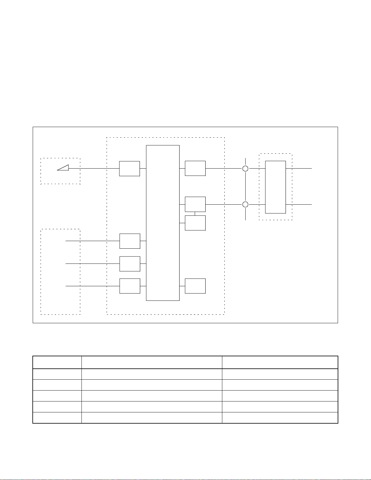
2. HARDWARE CONFIGURATION
The system provi des PRT as a pr imary ra te I SDN interfa ce. DTI with DCH is avail able also. The hardwar e configuration is shown in Figure 2-1.
NT2
TE1
TE2
Dterm
DP/PB
G3FAX
ATTCON
ILC
ELC
LC
ATI
PBX
PRT
DTI
DCH
PLO
T
NT1
DSU
ISDN
NT1: Network Termination 1
NT2: Network Termination 2
TE1 : ISD N Terminal Equipme nt
TE2: Non ISDN Terminal Equipment
DSU: Digital Service Unit
DA: Data Adapter
PC: Person al C om p ut e r wi th V.24
Figure 2-1 Hardware Configuration
Table 2-1 Hardware
SYMBOL HARDWARE REMARKS
PRT PA-24PRTB-A IS D N p rimary rate Interfac e
DCH PA-2DCHA D-channel Handler
DTI PA-24DTR Digital trunk interface
PLO PA-CK16-A/17-A Phase Lock Oscillator
ILC PA-8ILCG ISDN Terminal Equipment
NDA-24305 CHAPTER 2
Page 3
Revision 1.0
Page 22
GENERAL INFORMATION
3. BASIC KNOWLEDGE
3.1 MESSAGE SEQUENCES FOR LAYER 3
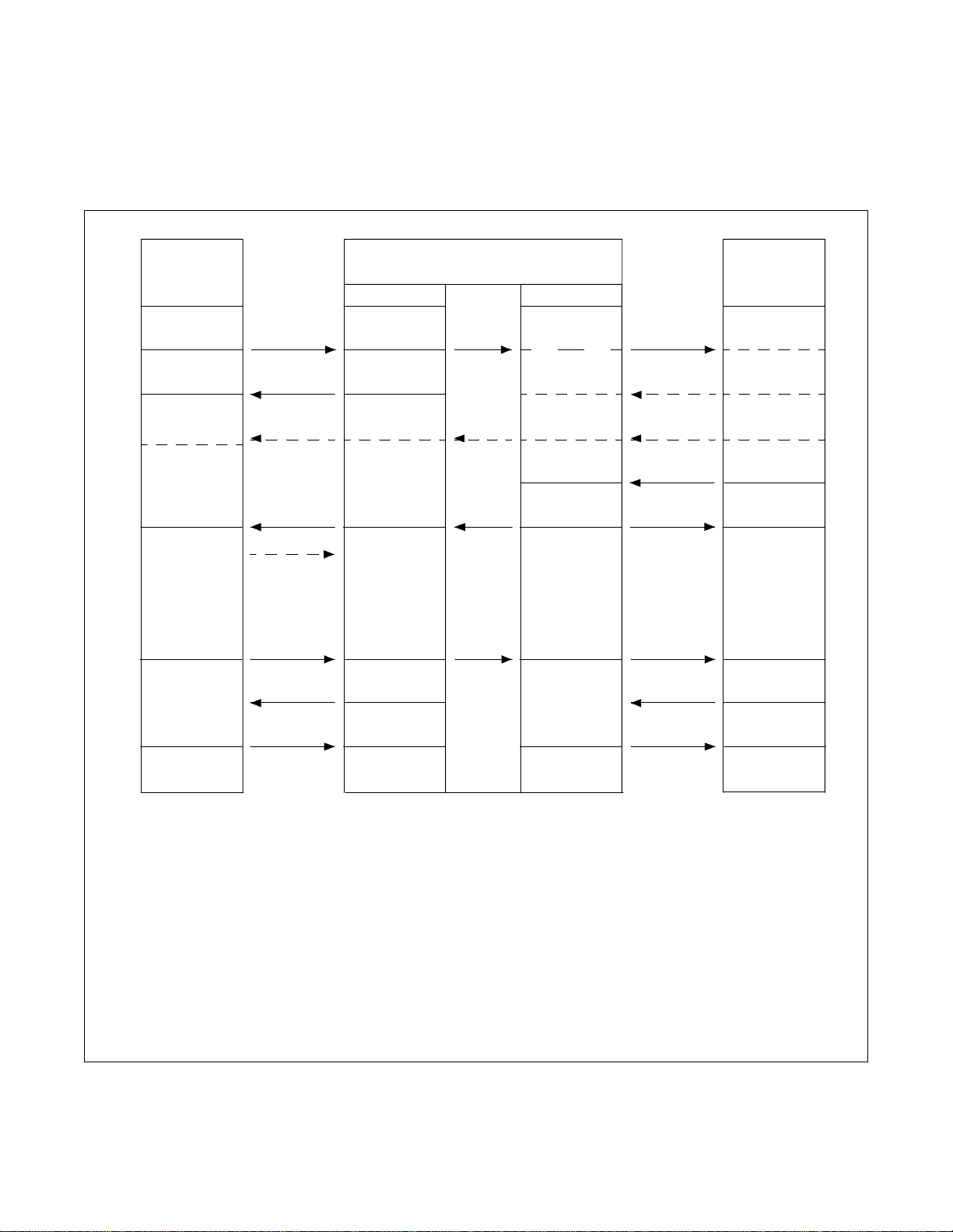
The message sequence for call establishment and clearing is shown in Figure 2-2.
State of
Originating
User Side
Null
(0)
Call Initiated
(1)
OG call
Proceeding
(3)
Call D e livered
(4)
Active
(10)
Disconnect
Request
(11)
Null
(0)
SETUP
CALL PROC
ALERT/PROG
CONN
CONN ACK
DISC
REL
RELCOM
OG Side
Null
(0)
Call Initiated
(1)
OG call
Proceeding
(3)
Call Delivered
(4)
Active
(10)
Disconnect
Request
(11)
Release
Request
(19)
Null
(0)
State of Network
IC Side
Null
(0)
Call Present
(6)
IC call
Proceeding
(9)
Call Received
(7)
Connect
Request
(8)
Active
(10)
Disconnect
Indication
(12)
Null
(0)
SETUP
CALL PROC
ALERT/PROG
CONN
CONN ACK
DISC
REL
RELCOM
State of
Termi nating
User Side
Null
(0)
Call Present
(6)
IC call
Proceeding
(9)
Call Received
(7)
Connect
Request
(8)
Active
(10)
Disconnect
Indication
(12)
Release
Request
(19)
Null
(0)
Note 1:
<Call established message> <Call clearing message>
ALERT: Alerting DISC: Disconnect
CALL PROC: Call Proceeding REL: Release
CONN: Connect RELCOM: Release Complete
CONN ACK: Connect Acknowl edge
PROGRESS: Progress
SETUP: Setup
Note 2:
CHAPTER 2 NDA-24305
Page 4
Revision 1.0
The number in ( ) shows Call state value for User or Network.
Figure 2-2 Message Sequences for Layer3
Page 23

GENERAL INFORMATION
3.2 BEA R E R CAPABILIT Y (B C) INFORMATION ELEMENT
The purpose of the Bearer Capability (BC) information element is to indicate a bearer service to be provided by
the network (ISDN). It contains only information which may be used by the network.
The Bearer Capability information element is used for compatibility checking in the connection as well as Low
Laye r (LLC)/High Layer (H LC) Capability.
The f ollow i n g show s th e rela ti on bet ween a term inal and BC.
Kind of T erminal BC
Analog single line telephone Speech
term
Digital telephone (D
) Speech
G3 (Group 3) Fax 3.1 kHz audio
Modem 3.1 kHz audio
DTE via Data Module/Adaptor Unrestricted digita l
G4 (Group 4) Fax Unrestricted digital
NDA-24305 CHAPTER 2
Page 5
Revision 1.0
Page 24

This page is for your notes.
CHAPTER 2 NDA-24305
Page 6
Revision 1.0
Page 25

CHAPTER 3 BASIC DATA ASSIGNMENT FOR ISDN
1. ISDN LINE ACCESS CODE ASSIGNMENT
To initiate seizure of an outgoing trunk, one of four methods - OGC, OGCA, LCR, LCRS - can be used in the
system. Among the four methods, however, “LCR” method alone can access an ISDN line. For this reason, be
sure to assign “LCR” as “Kind of service (SRV)” in the ASPA command. The following explains how to
program LCR data.
STEP 1: ANPD - Assign the first digit of the LCR access code for the ISDN line.
STEP 2: ASPA - Assign the LCR access code for a dummy route number.
- Any dummy route number can be used if the route number is not duplicated.
- When Sub Address Dialing is desired, assign SUB=1. (Refer to Feature “SUB ADDRESS
- PRESENT”)
- An example “Sub Address Dialing” from a station is shown below.
-00-81-35463-1111
9
- International Sub Address (SA)
Access Code
- Country Code
(CC)
-Subscriber
Number (SN)
-*5650#
ISDN Address
ISDN trunk access code (LCR)
- A station user may dial the Sub Address when he/she uses the ISDN trunk access code
with SUB=1. The call will be originated after Register Inter Digit Timer value if the
station user does not dial Sub Address.
- The Register Inter Digit Timer is determined by ASYD SYS1 INDEX 129. (Default data =
6 seconds.)
STEP 3: AMND- Assign the Maximum Necessary Digits (MND) for each Area/Office code (DC).
- DC must include ISDN trunk access code and ISDN address but not a Sub Address (SA).
- Analog/Digital Line Data (A/D) must be assigned as data 1 (Digital) for the DC which
includes ISDN trunk access code.
A/D = 1
STEP 4: ARNP - Assign the ISDN trunk access code to the ISDN Bch route number, but not a dummy route
number.
STEP 5: ARTD - Assign the following CDN data for the dummy route number.
TCL (CDN 6) = 1 or 4 (depending on the requirement)
L/T ( CDN 7) = 1
AC (CDN 13) = 1
- The other CDNs may be left at default value (data 0) for the dummy route.
NDA-24305 CHAPTER 3
Page 7
Revision 1.0
Page 26

BASIC DATA ASSIGNMENT FOR ISDN
STEP 6: AFRS - Assign Number Pattern Code (NPC) and Outgoin g Route Sele ction P attern Number (OPR)
for the dummy route number.
- NPC may include ISDN trunk access code and ISDN address but not a Sub Address (SA).
- OPR is a kind of intermediator between AFRS and AOPR . Therefore any number may be
used from 1 through 4000. (Be careful not to assign duplicat ed OPR.)
STEP 7: AOPR - Assign ISDN Bch route number to the OPR which has been assigned in the AFRS
command.
- Since the system should transmit only ISDN address, skip the ISDN trunk access code.
- Route advance is available by programming RA, E and RT. OVFT is also available.
- ACMO is available with programming P N L.
- ATCP and/or ASDC is available with programming TDPTN.
STEP 8: ARSC - Assign RSC that allows RRIs for both ISDN Bch trunk route and the dummy route but not
for ISDN Dch trunk route.
For the Bearer Capability (BC) in ISDN;
Note:
Caller should provide the following service class data
ASFC - SFI48 = 1 (for 3.1 kHz audio) ---- Group 3 Fax. Mode
SFI48 = 0 (for speech)
m
CHAPTER 3 NDA-24305
Page 8
Revision 1.0
Page 27

2. ISDN TRUNK DATA ASSIGNMENT
STEP 1: ASYD - Assign the following indexes.
BASIC DATA ASSIGNMENT FOR ISDN
SYSl Index 91: Single PLO b7
b6 b5 b4
0 1 0 1
Dual PLOs b7
b6 b5 b4
1 1 1 1
SYSl Index 186: CCIS/ISDN in service b6 b6
SYSl Index 187: always 00 (hex)
SYSl Index 220: ISDN is in serv i ce For BRI Type of Interface
STEP 2: ARTD - Assign the route data for both Bch and Dch.
Data for Bch/ Data for Dch
2 - ONSG : 2/2 4 - INSG : 2/2 5 - TF : 3/0 6 - TCL : 1/1
7 - L/T : 1/1 8 - RLP : 2/2 10 - SMDR : 1/0 15 - LSG : 12/13
28 - ANS : 1/1 30 - PAD : 4/7 31 - OGRL : 1/0 32 - ICRL : 1/0
34 - GUARD : 1/0 45 - A/D : 1/0 50 - DPLY : 1/0 63 - LY ER1 : 0
65 - INT :
Note 1
66 - DC :
Note 2
The other data should be “0” (default data).
1 0 (When b6=1, ISDN service is invalid.)
Note 1:
Note 2:
INT (CDN65): 1 N-ISDN2
2 Australia
3 INS 1500
4 ITU (CCITT), ETS I
5 AT&T (#4/#5 ESS)
6 INS 64
7 NT DMS 100 / DMS 250
8 Not used
9 TTC Q931a protocol Tie Line (Japan)
10 Q-SIG. (ETS 300 172)/IS-11572
For “SUB ADDRESS - ADDRESSING”, assign “0”. (Refer to “SUB Addr ess - Addr essing ” in Chapter
6.)
For “DID ADDRESSING”, refer to “DID Addressing” in Chapter 6.
NDA-24305 CHAPTER 3
Page 9
Revision 1.0
Page 28

BASIC DATA ASSIGNMENT FOR ISDN
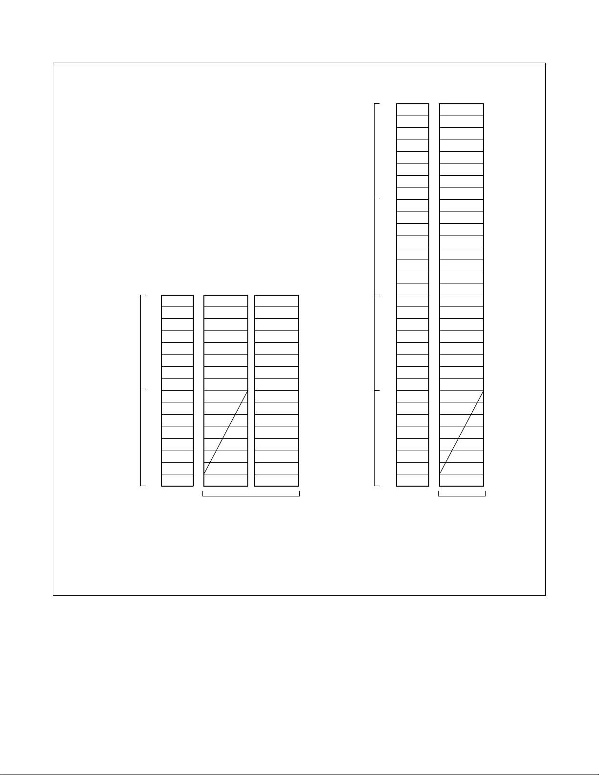
STEP 3: ATRK - Assign the trunk data for Bch only here. Note that the data assignment for Dch must be
performed after the ACSC command assignment.
- How Bch and Dch LEN appear in PIM is shown in Figure 3-1 and Figure 3-2.
- As seen from those Figures, the number of B-channels and D-channels are:
24 PRT (B channel × 23, D channel × 2)
- Regarding the route number of the Bch assigned by the ARTD command, assign the Bch’s
trunk number and Line Equipment Number (LEN).
The above is for the basic (minimum) data. Refer to Chapter 4, ”Commands Concerning ISDN Data
Note:
Assignment” for others.
CHAPTER 3 NDA-24305
Page 10
Revision 1.0
Page 29
Odd
Number
Group
Even
Number
Group
Bch 8
Bch 1
Dch 2
Note
7
6
5
4
3
2
Dch 1
Bch 23
Bch 9
Level Slot x Slot y
LV 7
6
5
4
3
2
1
LV 0
LV 7
6
5
4
3
2
1
LV 0
Note
22
21
20
19
18
17
16
15
14
13
12
11
10
BASIC DATA ASSIGNMENT FOR ISDN
Level Slot
Dch 1
Bch 23
Bch 1
Dch 2
Group
n+3
Group
n+2
Group
n+1
Group
n
LV 7
6
5
4
3
2
1
LV 0
LV 7
6
5
4
3
2
1
LV 0
LV 7
6
5
4
3
2
1
LV 0
LV 7
6
5
4
3
2
1
LV 0
Note 1:
Note 2:
IF 16 PORTS/ SLOT
IF 32 PORTS/SLOT
Slot x and Slot y must be in the same HW.
The even-numbered module group, Unit 0, Group 0 cannot be assigned as Dch LEN data.
Figure 3-1 ATRK for 24PRT
NDA-24305 CHAPTER 3
Page 11
Revision 1.0
Page 30
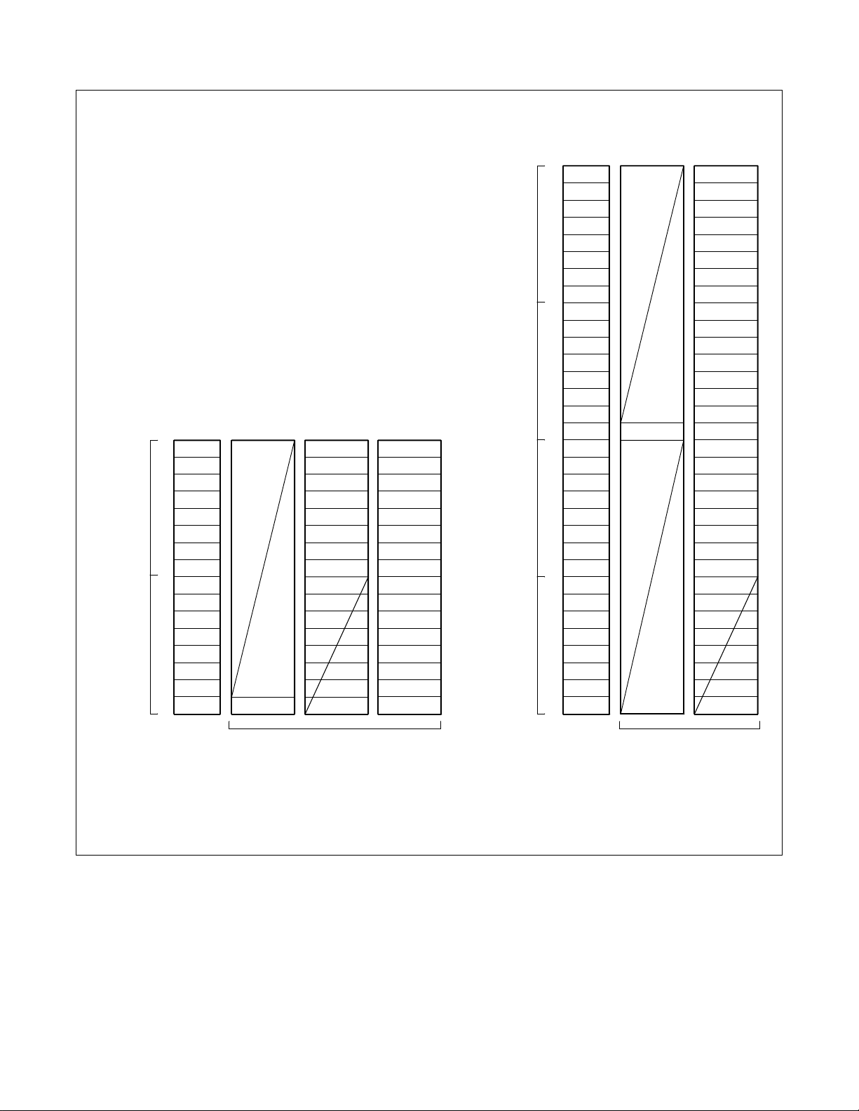
BASIC DATA ASSIGNMENT FOR ISDN
• When #0 DCH of 2DCH card is used.
Odd
Number
Group
Even
Number
Group
Level Slot x Slot y
LV 7
6
5
4
3
2
1
LV 0
LV 7
6
5
4
3
2
1
LV 0
Slot
Dch 2
Note
Bch 8
Bch 1
Dch 1
7
Bch 23
6
5
4
3
2
Bch 9
Note
22
21
20
19
18
17
16
15
14
13
12
11
10
Group
n+3
Group
n+2
Group
n+1
Group
n
Level Slot
LV 7
6
5
4
3
2
1
LV 0
LV 7
6
5
4
3
2
1
LV 0
LV 7
LV 0
LV 7
LV 0
Dch 2
6
5
4
3
2
1
6
5
4
3
2
1
Slot
Dch 1
Bch 23
Bch 1
IF 16 PORTS/SLOT
Note 1:
Note 2:
Slot x and Slot y must be in the same HW.
The even-numbered module group, Unit 0, Group 0 cannot be assigned as Dch LEN data.
Figure 3-2 AT RK for 24DTR + 2DCH
STEP 4: ADPC-Assign Point Code for both Bch route and Dch route.
- The values for a Point Code is 1 through 16383. You can assign any number as the Point
Code for them, however, do not duplicate the Point Code which is used for No. 7 CCIS.
CHAPTER 3 NDA-24305
Page 12
Revision 1.0
IF 32 PORTS/SLOT
Page 31

STEP 5: ACSC - Assign Dch and Bch location for CSCG.
- The values for CSCG is 130 through 255.
- Even number CSCGs are used for Dch location and odd number CSCGs are used for Bch
location. Although Bch location is the same as Dch location when PRT is used.
- CCH, which represents Dch and Bch location, is assigned as shown below.
BASIC DATA ASSIGNMENT FOR ISDN
CCH: XX
X XX
Group (00 - 23)
Unit (0 - 3)
Module Group (00 - 07)
- CCH must be assigned as the first group in the highway to which PRT is mounted.
- CCH=00000 is prohibited.
- Assign the same LEN in CIC GROUP (0~7) for a CSCG when PRT is used for 23B+D
- Examples of ACSC assignment are shown below.
00-03 04 05 06 07 08 09
01 03 05 07 09 11
00 02 04 06 08 10
HW0 HW1 HW2
(1) Condition: When 24PRT is mounted i n S lot 0 7 o f PIM0, ACSC data is as follows.
CSCG CCH CIC GROUP CSCG CCH CIC GROUP
130
(for Dch)
00004
00004
00004
00004
00004
00004
00004
00004
0
1
2
3
4
5
6
7
131
(for Bch)
00004
00004
00004
00004
00004
00004
00004
00004
0
1
2
3
4
5
6
7
The location of DCH (Dch Handler) which is built in PRT must b e assigned in the parameter “CCH” of
Note:
this command.
NDA-24305 CHAPTER 3
Page 13
Revision 1.0
Page 32

BASIC DATA ASSIGNMENT FOR ISDN
(2) Condition: 24DTR is mounted in Slot 07 of PIM0 and 2DCH is mounted in Slot 05 of
PIM0, ACSC data is as follows.
CSCG CCH CIC GROUP CSCG CCH CIC GROUP
Note 1:
Note 2:
130
(for Dch)
The location of DCH (Dch Handler) must be assigned in the “CCH” parameter of this command.
Above is an example when #0 DCH of PA-2DCH circuit card is used.
00002
00002
00002
00002
00002
00002
00002
00002
0
1
2
3
4
5
6
7
131
(for Bch)
00004
00004
00004
00004
00004
00004
00004
00004
0
1
2
3
4
5
6
7
STEP 6: ACIC1 - With respect to PC assigned in the ADPC command, assign CSCG of the Dch assigned in
the ACSC command.
STEP 7: ATRK - Assign the trunk data for Dch referring to Figure 3-1 and 3-2.
STEP 8: MBTK - Cancel Make Busy Status of all B channels in the PRT card.
Circuit card must be initialized after this assignment.
Note:
CHAPTER 3 NDA-24305
Page 14
Revision 1.0
Page 33

BASIC DATA ASSIGNMENT FOR ISDN
3. CALLING NUMBER PATTERN DATA (CNP) ASSIGNMENT
Calling party number can be transmitted included in the ISDN messages through ISDN network. This function
provides the PBX use r with a varie ty of ISDN servi ces. This section descri bes some conditions for progra mming
data related with this function when interworking with the Fusion link as shown Figure 3-3.
Example)
ISDN
network
RT=6, LGRT=16
Station B (6 10000)
DID no. : 0297-74-1234
Since Station A originates a call via the ISDN line established in Node A in this example, the calling
Note:
party number to be received by the destination station is the DID No. programmed at Node A.
Node B
FCCS
Node A
ISDN
network
RT=3, LGRT=13
Stati on A (600000)
DID no. : 0471-81-1 96 9
Destination' s
number
03-3454 -1111
Calling part y number
0471-81-1969
.
Note
Figure 3-3 Calling Number When Interworking with FCCS Link
(1) This data should be assigned at NCN.
(2) Calling Number Pattern (CNP) for the outgoi ng call (CALLING P ARTY RECOGNITION) and that for the
incoming call (SID TO NETWORK-PRESENT) should be separated.
(3) The services to be rel a t ed with this feature are shown below.
• CALL PARTY RECOGNITION SERVICE (DIRECT-IN-TERMINATION)
• CALL PARTY RECOGNITION SERVICE (CALL FORWARDING-ALL CALLS/BUSY LINE/
DON’T ANSWER)
• SID TO NETWORK-PRESENT/SID TO NETWORK-PRIVACY
PROGRAMMING
ACNPN and ACNDN command must be use d i n pairs. The use of oth er p airs, for e xampl e ACNP and AC NDN,
is not recommended.
(1) Originating from the non-ISDN terminal
STEP 1: ACNPN - Apply the Calling Number Pattern number to the logical route to be provided SID to
Network-Present.
OG/IC=O (Outgoing Call; SID to Network-Present)
LGRT=the route used for SID to Network -Present
CNP=Calling Number Pattern (1~1023)
* The detail for the pattern is programmed with the ACNDN command.
NDA-24305 CHAPTER 3
Revision 1.0
Page 15
Page 34

BASIC DATA ASSIGNMENT FOR ISDN
STEP 2: ACNDN - Assign the number of digits to be added to or omitted from the calling party number data
for each Calling N u mber Pattern programmed in ACNPN.
CNP=Calling Number Pattern assigned with ACNPN command.
SKIP=the number of digits to be skipped.
ADD=the number of digits to be added.
DC=the number to be skipped or added.
Do not assign “0” at both “SKIP” and “ADD” parameter.
Note:
[Example Data]
Programmed Data
ACNPN: OG=O, LGRT=2, CNP=2
ACNDN: CNP=2, SKIP=0, ADD=6, DC=047182
In this case, 0471-82-4211, th e DID number for the station (station no. 511), is sent to the terminating node.
PBX
Bch (LGRT=2)
PRT ISDN Network
“0471-82-4211 ” is receive d.
Station 511
DID no.: 0471 -82 -421 1
PBX
FCCS
(2) Originating from the ISDN terminal
STEP 1: ACNPN- Apply the Calling Number Pattern data to the log ical rout e to be provid ed SID t o Network-
Present.
OG/IC=O (Outgoing Call; SID to Network-Present)
LGRT=the route for SID to Network -Present
CNP=Calling Number Pattern (1~1023)
*The detail for the pattern is programmed with the ACNDN command.
STEP 2: ACNDN- Assign the Calling Number data.
CNP=Calling Number Pattern assigned with ACNPN command.
SKIP=the number of digits to be skipped.
ADD=the number of digits to be added.
DC=the number to be skipped or added.
[Example Data]
Programmed Data
ACNPN: OG=O, LGRT=2, CNP=2
ACNDN: CNP=2, SKIP=0, ADD=6, DC=047182
When ISDN terminal 221 (DID no. is not assigned)
originates a call
DID no. assigned to the ILC port no. 222 is sent
PBX
DID no.
0471-8 2-3664
222ISDN
Terminal
Port no.
220
ILC
221 DID no. is not assigned
DID no. of Station 222 is 0471-82-3665
FCCS
When ISDN terminal 222 (DID no. is 0471-82-3665)
originates a call
DID no. of ISDN terminal 222 is sent
PBX
Bch (LG R T=2)
PRT
ISDN terminal
221
222
ISDN net work
Calling party number
0471-82-3664
0471-82-3665
CHAPTER 3 NDA-24305
Page 16
Revision 1.0
Page 35

CHAPTER 4 COMMANDS CONCERNING ISDN DATA ASSIGNMENT
1. GENERAL
This chapter explains commands concerning ISDN. Commands explained in Chapter 3, “Basic Data
Assignm ent for IS D N ” are not included in this chapter.
• ASYD: Assignment of System Data Note
• ASFC: Assignment of Service Feature Class Data Note
• ARTD: Assignment of Route Class Data Note
• ARTI: Assignment of Trunk Application Data
This chapter covers only Index (data) related to ISDN.
Note:
NDA-24305 CHAPTER 4
Page 17
Revision 1.0
Page 36

COMMANDS CONCERNING ISDN DATA ASSIGNMENT
2. COMMANDS
2.1 ASYD: ASSIGNMENT OF SYSTEM D ATA
SYSTEM
DA T A
TYPE
(SYS)
SYSTEM
DA T A
INDEX
(INDEX)
0-511
76
DATA
(DATA)
00-FF
(Hex)
BIT CORRE-
SPONDING
DATA
DATA
0/1
0b
0b
0b
0b
0b
0b
BIT
b
b
b
0
1
2
3
4
5
6
7
0
SYSTEM DATA CONTENTS
Not used Table Development:
Same Num ber Special Access Code
Data (ASPS command)
Common or Separate
Day/Night Data Tables.
0/1 = Common/Separate
Call Forwarding Service by Calling
Number Data (AFCP command)
0/1 = Common/Separate
Not used
Note:
When data
tables are
designated as
“Common”,
the Day mode
designation
must be used
in the
respective
commands.
0/1 = Link Re-Connection Not Involved/Link Re-Connection
Involved
Note:
An Interoffice transfer service is available. For example,
with No. 7 CCIS, a caller has called outside their own
1
office but is actually talking with somebody in their own
office. This bit is used to reconfigure links so they are not
wasted in call transfer service.
b
Res tricti on check based on t he caller’s restriction cla ss when the
1
outgoing trunk is using the No. 7 CCIS in a tandem connection.
0/1 = No Chec k/Check
186
0b
0b
0/1 = -/No. 7 CCIS Loop-Back Test in progress
2
Not used
3
b
Serial C al l- L o op Release:
4
0/1 = Out (CCSA key)/In Service (No CCSA key)
b
Clearing of the buffer memory for use in the centralized
5
management report (For CCIS).
0/1 = not necessary/necessary
b
CCIS or ISDN:
6
0/1 = Out/In Service
b
Centralized IC Billing Office Code:
7
0/1 = Ineffective/Effective
187 00 Data Bus used for CCIS/ISDN cards (Assign 00 Hex)
CHAPTER 4 NDA-24305
Page 18
Revision 1.0
Page 37

COMMANDS CONCERNING ISDN DATA ASSIGNMENT
SYSTEM
DATA
TYPE
(SYS)
1
SYSTEM
DATA
INDEX
(INDEX)
0-511
220
DATA
(DATA)
00-FF
(Hex)
BIT CORRE-
SPONDING
DA T A
DATA
0/1
BIT
b
b
b
b
b
b
0
b
b
SYSTEM DATA CONTENTS
Protocol of ISDN Terminal (BRI station)
0
0: Japan (INS64)
1: U.S.A. (5ESS)
1
2: Australia (TPH 1962)
3: Not used
2
4: Not used
5: N-ISDN1
3
6-15: Not used
RA (Rat e Ad ap t ati on) for ISDN Termin al
4
0: RA designated by ADA2 command
1: V.110/X.30
5
2: Not used
3: Not used
ISDN service (When Ind ex 186 bit 6 = 1 )
6
0/1 = In Service/Out of Service
ISDN Trunk Layer 3 Timer
7
0/1 = Stop/Activate
Note 1
Note 1:
Call Forwarding Service by Calling
b
0
Number Data (“AFCP” command)
226
0b
0b
0b
0b
0b
0b
0b
1
2
3
4
5
6
7
Not used
Normally assign “0”. (Only specif ic service needs data “1” in this bit.)
Related Layer3 Timer: T303, T310, T313.
Separate or Common
Tenant Data Table
development for the
respective commands
0/1 = Separate/
Common
Note:
When data “1”
is assigned, data
must be assigned
for Tenant 1 (TN
= 1) in the
respective
commands.
NDA-24305 CHAPTER 4
Page 19
Revision 1.0
Page 38

COMMANDS CONCERNING ISDN DATA ASSIGNMENT
SYSTEM
DATA
TYPE
(SYS)
1
SYSTEM
DATA
INDEX
(INDEX)
0-511
230
248
DATA
(DATA)
00-FF
(Hex)
BIT CORRE-
SPONDING
DATA
DA T A
0/1
0b
0b
0b
BIT
0-b6
b
0-b3
b
7
4
b
5
6
b
7
SYSTEM DATA CONTENTS
Not used
Timing for receiving or sending ISDN/CCIS message.
0/1 = 32 ms/128 ms
Maximum Digits for Call Forwarding External Restriction (for
Australia only)
0: 12 digits A: 10 digits
1-8: 8 digits B: 11 digits
9: 9 digits C-F: 12 digits
Not used
Malicious call (ISDN) Service
Note 1
0/1 = Out/In Service
Not used
Tone to be sent out when the handset has been lifted off-hook at
the stat ion on w hi ch C.F.-Al l C alls s er vice is set.
0/1 = Dial Tone (DT)/Special Dial Tone (SPDT)
Note 1:
Note 2:
T321 Timer (SERV ACK receiving Timer)
478
Timer Value = MTC x 1 sec.
(Default data 00 Hex: 30 sec.)
Timer for Dch Back u p
Waiting Timer for a changeover when an ACT Dch detects Layer
2 down in a self or facing office.
479
Timer Value = MTC x 1sec.
(Default data 00 Hex: 0 sec.)
Available in Au stralia and U.A.E.
For AT&T/Northern Telecom in U.S.A.
Note 2
b7 b6 b5 b4 b3 b2 b1 b0
MTC
Note 2
b7 b6 b5 b4 b3 b2 b1 b0
MTC
CHAPTER 4 NDA-24305
Page 20
Revision 1.0
Page 39

COMMANDS CONCERNING ISDN DATA ASSIGNMENT
2.2 ASFC: ASSIGNMENT OF SERVICE FEATURE CLASS DATA
SFI 31: For SID to Terminating User-DTE
0 = –
1 = SID to Terminating User-DT E
SFI 48: For Bearer Service
0 = Speech
1 = 3.1 KHz Audio (Modem, G3 Fax)
SFI 94: For SID to Network - Privacy [CLIR]
0 = –
1 = SID to Network - Privacy
SFI 175: F or Advice of Charge (AOC) - Receipt and Display of AOC from a Foreign Q-SIG NETWORK
0 = Out of Service
1 = In Service
2.3 ARTD: ASSIGNMENT OF ROUTE CLASS DATA
H1 (CDN96) ISDN H1 Switching
0 = –
1 = In Service
CI (CDN98) ISDN transmitting information
0 = –
1 = 16-Digit Caller Number service, Attribute Information Notification servi ce
(BC, LLC, HLC) and Calling Sub-Address Transfer service
2-15 = –
ADVPRA (CDN111) ISDN PRI Failure Routing Service
0 = –
1 = In Service
This data is valid for dummy routes.
Note:
CMRT (CDN115) Common use of Route Numbers of ISDN trunks
0 = –
1 = In Service
BOB (CDN118) Broad Band
0 = 64K
1 = N × 64K
NDA-24305 CHAPTER 4
Page 21
Revision 1.0
Page 40

COMMANDS CONCERNING ISDN DATA ASSIGNMENT
2.4 ARTI: ASSIGNMENT OF TRUNK APPLICATION DATA
RST (CDN1) Assignment of Restart
0 = Restart Send per Individual Channel
1 = –
2 = –
3 = Restart not Send
HMT (CDN2) When assigning this data, zero (0) should always be entered.
TRCRST (CDN3) Call Restriction b y Information transf er rate in Bearer Capability Information Element
0 = No restriction
1 = Data call restriction (Unrestricte d di g ital, Restricted digital and Video da ta calls are
restricted.)
2 = Speech call restriction (Speech, 3.1 KHz audio and 7KHz audio calls are restricted.)
3-15 = –
TRSRST (CDN4) Call Restriction b y Information transf er rate in Bearer Capability Information Element
0 = No restriction
1 = 384 kbps (H0) call is restricted
2 = 1536 kbps (H11)/1920 kbps (H12) call is restricted
3 = 384 kbps and 1536 (H11)/1920 (H12) kbps calls are restricted
4-15 = –
T309LNK (CDN5)Assignment of Timer T309 for Data Link Failure
0 = Layer 2 Alarm with T309 is Disabled
1 = Layer 2 Alarm [Te mporary] with T309 is Enabled
2 = Layer 2 Alarm [Permanent] with T309 is Enabled
3 = –
T309CON (CDN6)Assignment of Timer T309 for Layer 1 Failur e
0 = Layer 1 Alarm with T309 is Disabled
1 = Layer 1 Alarm [Te mporary] with T309 is Enabled
2 = Layer 1 Alarm [Permanent] with T309 is Enabled
3 = –
LLCRST (CD N7) Call restrict ion by u ser rat e in Low Layer Capability Information Elem e nt
0 = No restriction
1-31 = Call which includes this user rate value is restricte d Note 1
Note 1:
User ra t e v a lue is based on ITU-T Q-931.
DTRT (CDN11) Detection of ALL 1 alarm signal (DTI Layer 1 alarm)
0 = –
1 = Detection of ALL 1 alarm signal as a Layer 1 alarm
TMPRT (CDN12) Temporary Route Information over CCIS
0 = –
1 = In CC IS, the route informatio n can be transferred b y th e call con tr ol message s.
Moreover, the call restriction ca n be ch eck ed re fe r r i n g t o t his route info rm a tion.
CHAPTER 4 NDA-24305
Page 22
Revision 1.0
Page 41

COMMANDS CONCERNING ISDN DATA ASSIGNMENT
IRL (CDN15) Clear call when DTI alarm is detected.
0 = –
1 = Clear call when DTI alarm is detected Note 2
Note 2:
This data should be set when there is no Dch in the physical DTI.
MTC (CDN16) Assignment of Timer T309 Value. Restoration timer (TC×MTC) sec.
0-15 = TC (CDN18) × MTC (Restart timer value)
TC (CDN17) Timer T309 Counter Value
0 = –4 = 30sec.
1 = 64 msec.5 = 5 m in.
2= –6 = 1 sec.
3= 2 sec.7 = –
DVRST (CDN20) Call restriction while Tie Line is backed up on ISDN.
0 = No Restriction
1 = Speech call restriction (Speech. 3.1 kHz audio, 7 kHz audio calls are restricted.)
2 = Data call restriction (Unrestricted digital, restricted digital and Video data are
restricted.)
3 = Both Speech and Data call s are restricted.
RSCT (CDN21) Call restriction by Temporary Route Information Note 3
0 = No Restriction
1 = Restriction
Note 3:
This data is effective when TMPRT = 1.
ROCG (CDN22) Outgoing Call Account by Temporary Route Information Note 4
0 = –
1 = Effective
Note 4:
This data is effective when TMPRT = 1.
RICG (CDN23) Incoming Call Account by Temporary Route Information Note 5
0/1 = Out of Service/In Service
Note 5:
This data is effective when TMPRT = 1.
STSENQ (CDN24) Status Inquiry Message Send Note 6
0/1 = Out of Service/In Service
Note 6:
This data is not effective in Australia.
RETMSG (CDN30) Return Message for Connect ISDN LINE with Analog Trunk
0 = CALL PROC. + ALERT
1 = CALL PROC. + ALERT or CALL PROC. + PROGRESS
NDA-24305 CHAPTER 4
Page 23
Revision 1.0
Page 42

COMMANDS CONCERNING ISDN DATA ASSIGNMENT
ANI (CDN31) Timing to deman d ANI Informatio n
0 = There is no ANI demand at Incoming call
1 = After receiving 1st digit
2 = After receiving 2nd digit
3 = After receiving 3rd digit
4 = After receiving 4th digit
5 = After receiving 5th digit
6 = After receiving 6th digit
7 = After receiving 7th digit
SRV (CDN32) Additional Service Selection Note 7
Bit0: Advice of Charge (AOC)
0 = Valid
1 = Invalid
Bit1: Malicious Call Trace (MCT)/Malicious Call Identification (MCID)
0 = Valid
1 = Invalid
Bit2-Bit6: –
Bit7: For TON (CDN28) and/or NPI (CDN29)
0 = Invalid
1 = Valid
Note 7:
Input this data by a decimal.
TON (CDN33) Type of Number Note 8
0 = Unknown
1 = International Number
2 = National Number
3 = Network Special Number
4 = Subscriber Number
5=–
6 = Abbreviated Number
7 = Re se rved fo r Extension
Note 8:
This dat a is effective when ARTD CDN65 (INT) = 4 and SR V ( CDN2 7) bi t7 = 1 .
NPI (CDN34) Numbering Plan Identification Note 9
0 = Unknown
1 = ISDN/Telephony Numbering Plan
2=–
3 = Data Numbering Plan
4 = Telex Numbering Plan
5-7 = –
8 = National Standard Numbering Plan
9 = Private Numbering Plan
10-14 =–
15 = Reserved for Extension
Others =–
Note 9:
CHAPTER 4 NDA-24305
Page 24
Revision 1.0
This data is effective when ARTD CDN65 (INT) = 4 and ARTI SRV (CDN27) bit7 = 1.
Page 43

COMMANDS CONCERNING ISDN DATA ASSIGNMENT
L/T (CDN35) Local/Toll
Note 10
0 = Local
1=Toll
Note 10:
Only for Russia
ECCIS (CDN36) Event Based CCIS (E-CCIS) for the public ISDN Line
0/1 = Out of Service/In Service
ECCISTM (CDN3 7) Rele ase tim er for E-CCIS Line
0 = 3 minutes (Default setting)
1 = 15 seconds
2 = 30 seconds
3 = 1 minute
4 = 2 minutes
5 = 5 minutes
6 = 10 minutes
7 = 15 minutes
8 = 30 minutes
9 = 1 hour
10-13 = Not used
14 = Immediately after call completion
15 = Not released
ECCISOB (CDN38) OG Billing for E-CCIS Line
0/1 = Out of Service/In Service
ECCISIB (CDN39) IC Billing for E-CCIS Line
0/1 = Out of Service/In Service
SPMET (CDN40) Meter Pulse Observation Control
0=–
1 = Low to High Transition
2 = High to Low Transition
3 = Low to High & High to Low Transition
ECCISTD (CDN42) Addressing Information used in E-CCIS
0 = Called DID Number
1 = Called Sub Address
MFCG2 (C D N 43) Calling Part y C atego ry
0 = Subscriber with Priority
1 = Subscriber without Priority
OPCC (CDN44) Optimal Call Control
0/1 = In Service/Out of Service
INTD (CDN47) Interface Detail Note 11
0=Q-SIG
1 = IS-11572
NDA-24305 CHAPTER 4
Page 25
Revision 1.0
Page 44

COMMANDS CONCERNING ISDN DATA ASSIGNMENT
JECCIS (CDN48) Common Use with E-CCIS RT Note 11
0/1 = Out of Service/In Service
ECCIS2 (CDN49) E-CCIS System Note 11
0 = Fixed Channel System
1 = Common Channel System
2=Not used
3=Not used
Note 11:
Valid since Series 7300 Release 4.
CTCF (CDN52 ) SS-CT/SS-CF Servi ce Note 12
0/1 = Out of Service/In Service
Note 12:
Valid since Series 7400 Release 8.
RERT (CDN53) Rerouting function (used in conjunction with SS-CT/SS-CF service) Note 13
Note 13:
Valid since Series 7400 Release 8.
For the other CDNs in trunk application data, zero (0) should always be entered.
CHAPTER 4 NDA-24305
Page 26
Revision 1.0
Page 45

CHAPTER 5 GATEWAY SERVICE
This chapter explains data assignment for ISDN gateway service. Refer to ISDN Features and Specifications for
availability of each Gateway Service on the Fusion Network.
Table 5-1 Gateway Service List (1/4)
SERVICE
FEATURE
CODE
A-76 Alternate Routing-PRI
A-88 Automatic Call Distribution-PRI
A-92 Announcement Service-PRI
A-94 Automatic Circuit Assurance-PRI
A-96 Automatic Trunk Test-PRI
B-19 Boss-S ecretary Transfer-PRI
B-22 Boss-S ecretary Override -PR I
SERVICE FEATURE NAME R EMARKS
C-95 Call Forwarding-All Calls-PRI
term
C-95D Call Forwarding-All Calls-D
-PRI
C-96 Call Forwarding-Busy Line-PRI
C-97 Call Pickup-Group-PRI
term
C-97D Call Pickup-Group-D
-PRI
C-98 Call Transfer-Attendant-PRI
C-99 Call Transfer-All Calls-PRI
term
C-99D Call Transfer-All Calls-D
-PRI
C-100 Consultation Hold-All Calls-PRI
term
C-100D Consultation Hold-All Calls-D
-PRI
C-101 Call Forwarding-Intercept/Announcement-PRI
C-102 Call Pickup-Direct-PRI
C-114 Call Waiting-Terminating-PRI
C-119 Call Park-PRI
C-123 Call Forwarding-All Calls-Announcement-PRI
C-125 Call Forwarding-Intercept-PRI
C-129 Call Forwarding-Don’t Answer-PRI
D-115 Distinctive Ringing-PRI
NDA-24305 CHAPTER 5
Page 27
Revision 1.0
Page 46

GATEWA Y SERV IC E
Table 5-1 Gateway Service List (2/4)
SERVICE
FEATURE
CODE
D-116D Do Not Disturb-D
SERVICE FEATURE NAME R EMARKS
term
-PRI
D-117 Data Line Security-PRI
D-118 Data Privacy on Demand-PRI
D-119 Data Interface-Automatic Answer-PRI
D-120 Data Transparency-PRI
D-121 Data Communications-PRI
D-122 Data Uniform Numbering Plan-PRI
D-137 Direct-In Termination (DIT)-PRI
term
E-14D Elapsed Time Display-D
-PRI
F-21 Flexible Numbering of Stations-PRI
F-26 Faulty Trunk Report-PRI
H-14D Hands-Free Answer Back-D
term
-PRI
H-15 Hot Line-Outside-PRI
I-24 Incoming Call Identification-PRI
I-25 Incoming ISDN Call to Tie Line Connection-PRI
I-26 Indialing Through Main-PRI
I-27 Inter-PBX Coordinated Station Numbering Plan-PRI
I-28 ISDN Individual Calling Line Identification (ICLID)
I-36 Inter-Office Off-Hook Queuing-PRI
L-31 Least Cost Routing-3/6-Digit-PRI
L-32 LCR-Time of Day Routing-PRI
L-33 LCR-Attendant Manual Override-PRI
L-34 LCR-Automatic Ove rflow to DDD-PRI
L-35 LCR-Clocked Manual Override-PRI
L-42 Last Num b er Ca ll-PRI
term
L-42D L as t N u mber Called-D
-PRI
L-44 LDN Night Conn e ction- PRI
CHAPTER 5 NDA-24305
Page 28
Revision 1.0
Page 47

Table 5-1 Gateway Service List (3/4)
SERVICE
FEATURE
CODE
SERVICE FEATURE NAME R EMARKS
L-46 LDN Night Conn e ction-Outs i de-PRI
L-49 LCR-Special Line Warning Tone-PRI
M-71 Miscellaneous Trunk Access-PRI
M-72 Miscellaneous Trunk Restriction-PRI
M-73 Music On Hold-PRI
M-74 Modem Pooling-PRI
M-75 Multiple Call Forw arding-All Calls-PRI
N-20 Night Connection-Fixed-PRI
N-21 Night Connection-Flexible-PRI
N-22 Non-Delay Operation-PRI
GATEWAY SERVICE
N-29 Night Connection Outside-System-PRI
N-31 Nailed Down Connection-PRI
O-24 Outgoing Trunk Queuing-PRI
O-26 Outgoing Trunk Queuing-Deluxe-PRI
O-28 Off-Hook Queuing-PRI
O-30 Outgoing Trunk Queuing-Attendant-PRI
O-32 Overflow-UCD-PRI
P-37 Peg Count-PRI
P-38 Primary Call Restriction-PRI
P-39 PRI Trunk to Tie Line Connection with Pad Control
P-47 Paging Transfer-PRI
P-49 PRI Failsafe Routing
R-35 Restriction from Outgoing Calls-PRI
S-82 Speed Calling-System-PRI
term
S-82D Speed Calling-System-D
-PRI
S-83 Station Message Detail Recording System-RS232C-PRI
NDA-24305 CHAPTER 5
Page 29
Revision 1.0
Page 48

GATEWA Y SERV IC E
Table 5-1 Gateway Service List (4/4)
SERVICE
FEATURE
CODE
SERVICE FEATURE NAME R EMARKS
S-84 Speed Calling-Station-PRI
S-85 Speed Calling-Group-PRI
S-86 Simultaneous Voice and Data Transm i ssion- PRI
S-87 Synchronous Data Switching-PRI
S-88 SMDR for Data Call-RS232C-PRI
S-89 Speed Calling Override-System-PRI
S-107 Station Individual Trunk Access-PRI
T-37 Tandem Switching of Tie Trunk-2/4-Wire-PRI
T-38 Three-Way Calling-PRI
term
T-38D Three-Way Calling-D
-PRI
T-40 Toll Denial/Toll Diversion-PRI
T-41 Toll Restriction-3/6-Digit-PRI
U-6 Uniform Call Distrib ution (UCD) -PRI
CHAPTER 5 NDA-24305
Page 30
Revision 1.0
Page 49

ALTERNATE ROUTING-PRI
A-76 ALTERNATE ROUTING-PRI
1. General Descript ion
This feature is provided with LCR which automatically routes ISDN outgoing on-net calls over alternate
facilities when the first-choice trunk group is busy. The user selects the first-choice route by dialing the
corresponding acce ss code, and the equipment then routes the call through alterna te trunk groups only if the first
is busy. The PBX will also add or delete digits, when necessary, to complete the call to the desired station.
2. Operating Procedure
No manual operation is required.
3. Programming
STEP 1: Assign “ISDN Line Access Code” data referring to Chapter 3, “Bas ic Da ta Assign ment for ISDN ”
and the data for the alternate trunk access.
Note:
STEP 7: AOPR - Assign ISDN Bch route number and the alternate route number to
the OPR
STEP 8: ARSC - Assign RSC that allows Route Restriction Indexes (RRIs) for ISDN Bch
trunk route, the dummy route and the alternate trunk route.
STEP 2: Assign “ISDN Trunk” data referring to Chapter 3 , Section 2, “ISDN Trunk Data Assignment” and
the data for the alternate trunk.
NDA-24305 CHAPTER 5
Page 31
Revision 1.0
Page 50

AUTOMATIC CALL DISTRIBUTION-PRI
A-88 AUTOMATIC CALL DISTRIBUTION-PRI
1. General Descript ion
This feature allows Automatic Call Distribution (ACD) features to be activated for incoming calls from ISDN
trunks.
Table 5-1 ACD Features
CODE NO. FEATURE NAME AVAILABILITY
A-31 Abandoned Call Search ×
A-34 Assistance-ACD Agent ×
A-35 Automatic Answer ×
A-37 Availability-ACD Position ×
A-80 Announcements ×
B-21 Break Mode Not Applicable
C-35 Call Distribution to Agents ×
C-67 Call Transfer to Split Queue ×
C-68 Call Waiting Indication-LCD Display/CW Lamp ×
C-70 Calling Party Identification ×
C-108 Call Control Vector Not Applicable
C-127 Call Forwarding-Split ×
E-6 Emergency/Recorder ×
F-10 Function Groups (Splits) Not Applicable
F-25 Flexible ID Codes Not Applicable
H-20 Holidays Scheduling Not Applicable
L-19 Logon/Logoff Not Applicable
M-28 Monitoring-ACD Supervisor ×
M-29 Multiple Customer Groups (ACD Groups) Not Applicable
M-79 Multiple Supervisor Groups (Splits) Not Applicable
N-12 Night Service-ACD ×
N-14 Non-ACD Call Not Applicable
CHAPTER 5 NDA-24305
Page 32
Revision 1.0
Page 51

AUTOMATIC CAL L DISTRIBUTION-P RI
Table 5-1 ACD Features
CODE NO. FEATURE NAME AVAILABILITY
O-19 Overflow Outside-ACD ×
P-21 Priority Queuing-ACD ×
P-40 Pilot Numbers Not Applicable
P-45 Personal Emergency and Assist ×
Q-1 Queuing-AC D ×
R-19 Release-ACD Position ×
S-97 Split Display-ACD Position Not Applicable
S-98 Split Selection Not Applicable
T-24 Trunk Trouble Report-MIS ×
T-49 Tally Count ×
T-50 Time of Day/Week Routing Not Applicable
Z-1 Zip Tone-ACD Position ×
Note 1:
Note 2:
Note 3:
The features indicated “Not Applicable” are features not related to trunks.
ACD features are not available for incoming data calls from ISDN trunk.
When an incom ing ca ll p laced in a queue, th e cal l is au t o mat ically released in 90 seconds.
2. Operating Procedure
Refer to ACD System Manual.
3. Programming
STEP 1: Assign the Basic Data for ISDN. (Refer to Chapter 3, “Basic Data Assignment for ISDN”.)
STEP 2: Assign ACD D ata (Refer to ACD System Manual.)
NDA-24305 CHAPTER 5
Page 33
Revision 1.0
Page 52

ANNOUNCEMENT SERVICE-PRI
A-92 ANNOUNCEMENT SERVICE-PRI
1. General Descript ion
This feature allows a user from the ISDN trunk to hear a prearranged announcement when the user dials a
predetermi n ed access code.
This feature requires an announcement machine or a Digital Announcement Trunk (DAT).
Note:
2. Operating Procedure
1. The system receives the announcement trunk access code.
(a) If a multiple connection is made, the announcement is repeatedly sent out.
(b) If a single connection is made, the announcement is sent out only once and then the announcement
trunk is released. If the syste m data specifi es “Ringback Tone is to be sent”, Ringback T one is retu rned
to the caller after the announcement finishes.
2. The office data is checked for the following.
(a) Multiple or single connection.
(b) 30-second forced disconnection.
(c) Ringback Tone to be sent or not to be sent after the announcement finishes.
(d) Remote office answer signal sending to be sent or not to be sent.
3. The call is connected to the Announcement Trunk, and the caller hears the announcement.
4. If 30-sec. forced disconnection is specified, the Announcement Trunk is released 30 seconds after the call
has been connected to the Announcement Trunk, and the caller receives the Busy Tone. Otherwise, the call
remains connected to the Announcement Trunk until the caller hangs up.
3. Programming
STEP 1: Assign the Basic Data for ISDN (Refer to Chapter 3, “Basic Data Assignment for ISDN”).
STEP 2: Assign the announcement data (Refer to “[A-15] ANNOUNCEMENT SERVICE” in Feature
Programming Manual.)
CHAPTER 5 NDA-24305
Page 34
Revision 1.0
Page 53

AUTOMATIC CIRCUIT ASSURANCE-PRI
A-94 AUTOMATIC CIRCUIT ASSURANCE-PRI
1. General Descript ion
When a call connection time is less than or greater tha n a pre-determined time peri od, the system can dis play or
print a reference to it using this feature.
Note 1:
Note 2:
This feature cannot be activated without Station Message Detail Recording System-RS232C[S-10].
This feature is not activated for Station-to-Station or Station-to-Attendant calls under the following
conditions:
• When the station performs a switchhook flash.
term
• When the station presses the D
line/feature key (“HOLD”, “SHF”, or “TRF”).
• When the Attendant presses “HOLD” key.
• When the ca ll is ov err id d en by another call.
• Wh en the statio n a nswer s C a l l Waiti n g or At t e ndant Camp-On call.
2. Operating Procedure
No manual operation is required.
3. Programming
STEP 1: Assign the Basic Data for ISDN (Refer to Chapter 3, “Basic Data Assignment for ISDN”).
STEP 2: Assign SMDR data.
STEP 3: ASYD - System Data 1, Index 44 : bit 0=1 (Automatic Circuit Assurance is in service)
Index 45 : Short Duration Timer
Index 46 : Long Duration Timer
NDA-24305 CHAPTER 5
Page 35
Revision 1.0
Page 54

AUTOMATIC TRUNK TEST-PRI
A-96 AUTOMATIC TRUNK TEST-PRI
1. General Descript ion
The AUTOMATIC TRUNK TEST capability provides a functional test on a large number of ISDN tr unks at a
prearranged time. The results of the test are reported at the MAINTENANCE ADMINISTRATION
TERMINA L (MAT) [M-18]. The test ca n i nc l ude : R ingback Tone T est, 1 kHz Tone Test and Trunk Selection
Test, by having the proper Test Trunk termination at the distant office.
2. Operating Procedure
Refer to “[A-21] AUTOMATIC TRUNK TEST” in Feature Programming Manual.
3. Service Conditions
1. One LTST (PH-M23) card is required as additional hardware.
2. Trunks are tested in conjunction with the connecting office through the selected trunk, on a one at a time
basis. The following different trunk functions can be tested on all trunks in a specified group:
• Trunk selection
• Detection of Ringback Tone sent back from the connecting office after test number outpulsing.
• Detection of test tone (1 kHz) returned from Automatic Answer Trunk facility, if provided at the
connecting office.
3. As part of the AUTOMATIC TRUNK TEST facility, an Automatic Answer Trunk (AAT) is provided at the
PBX to answer incoming test calls. Upon terminating the incoming test call from the originating office
through a selected test trunk, the AAT generates a 1 kHz tone to the originating office as an
acknowledgement signal.
4. When ordering the execution of this feature via the MAT, the system will prompt for either “Immediate or
Scheduled Execution” of the AUTOMATIC TRUNK TEST. If Scheduled execution is chosen, the time
when the test begins is entered via the MAT. From the time the test is ordered until the completion of the
test, the MAT is dedicated to the AUTOMATIC TRUNK TEST function.
5. INDIVID UAL T RUNK AC CESS [I-4] must be available when activating this feature .
6. Trunk test data must be assigned by “ATTD” command.
7. This service is available to trunks that can receive PB signals.
4. Programming
Refer to “[A-21] AUTOMATIC TRUNK TEST” in Feature Programming Manual.
CHAPTER 5 NDA-24305
Page 36
Revision 1.0
Page 55

BOSS-SECRETARY TRANSFER-PRI
B-19 BOSS-SECRETARY TRANSFER-PRI
1. General Descript ion
This service fe ature allo ws a secret ary to voice-a nnounce a call to a boss when the secreta ry answe rs a call fr om
an ISDN trunk on the boss’ line.
2. Operating Procedure
1. Call ter m inate s to boss’ line .
term
2. Secretar y an s w ers the call on Boss’ line of Secretar y’s D
.
3. Secretary presses boss’ line key; incoming call is placed on hold, a signal tone is transmitted over the
speaker of boss’ D
term
, and boss and secreta ry c a n t alk by VOICE CALL-D
term
[V-2D].
Note 1
The LCD displays (Boss and Secretary):
ICM XXXX
(Time Disp lay)
term
4. If the “MIC” key of boss’ D
5. Secretary hangs up (
Note 2
line is placed on hold. At this time, boss’ line of Secretary’s D
answer the held call at any time. (
is on, Boss can converse HANDS FREE-D
); a signal tone is transmitted over the speaker of boss’ D
term
is placed on hold, too, and secretary can
Note 3
)
6. Boss lifts the handset, presses the boss’ line key, and answers the call. The LCD is displayed:
term
[D
Series III] [D
XFR XXXX
(Time Display)
Note 1:
If the boss is talking on another line or has a single line telephone, boss’ station rings and VOICE
term
Series E]
TRANSFER XXXX
(Time Display)
CALL [V-2D] cannot be activated.
term
[H-4D].
term
again, and boss’
Note 2:
If the boss answers before the secretary hangs up, the boss will talk to the secretary. At this time, the
secretary can talk to the incoming call, to the boss by pressing the boss’ line key or the transfer key.
Note 3:
If the boss doesn’t answer the held call in a specific time, secretary will be recalled by the held call.
3. Programming
STEP 1: ASFC - Assign SFI 51=1 (Boss-Secretary is in service) to the secretary station.
STEP 2: AKYD - Boss’ My-line must be assigned as a sub-line on the secretary’s phone .
Secretary must have D
Note:
term
for this operation. Boss may have a single line telephone.
NDA-24305 CHAPTER 5
Page 37
Revision 1.0
Page 56

BOSS-SECRETARY OVERRIDE-PRI
B-22 BOSS-SECRETARY OVERRIDE-PRI
1. General Descript ion
This feature enables a secretary to voice-announce a call from an ISDN trunk to a boss when he is currently on
his My-line.
2. Operating Procedure
Exam pl e: Station 200, Boss
Station 201, Se cretary
Boss is currently connected to Trunk “A”. Call from an ISDN trunk (Trunk “B”) terminates to Station 201,
intended for 200.
1. Secretar y an s w ers station 201.
2. Secretary asks caller to hold and presses “CALL HOLD” [C-6] feature key or “TRANSFER” key and dials
CALL HOLD [C-6] code (CALL WAITING-ORIGINATING [C-31] key can also be used).
Secretary hears Dial Tone.
3. Secretary presses “SPEED CALLING-ONE TOUCH” [S-26D] key on which BOSS-SECRETARY
OVERRIDE tone code, RECALL key and Boss’ station number (200) has been programmed.
4. Secretar y hears Ringba c k T one ; Boss receives three bursts of Waiting Tone.
<BOSS’ RESPONSE OPTIONS>
Operations when the boss converses with Trunk “A” while talking with trunk “B”.
1. Boss presses the “TRANSFER” key. If Boss has a single line telephone, flashes hook switch.
2. Boss c onverses wi t h Trunk “A” and Trunk “B” receives hold to n e (MUSIC ON HOLD [M-7]).
3. Boss presses the “TRANSFER” key again. If a single line telephone, f lashes hook switch again.
4. Boss converses with Trunk “B”. (THREE-WAY CALLING [T-2] is not available).
Other operations while Boss and Secretary are talking.
Case 1:
1. Boss or secretary presses the “TRANSFER” key.
2. The Boss and Secretary are disconnected; Boss converses with Trunk “A”, Secretary converses with Trunk
“B” respectively.
Case 2:
1. Boss hangs up and secretary converses with Trunk “B” again.
2. Boss’ station rings and Trunk “A” receives Ringback Tone.
3. Boss lifts the handset and converses with Trunk “A” again.
CHAPTER 5 NDA-24305
Page 38
Revision 1.0
Page 57

BOSS-SECRETARY OVERRIDE-PRI
Operation s w hen the boss ans w er s the secret ar y.
Case 1:
1. Boss presses the: “ANSWER” key or “TRANSFER” key. If Boss has a single line telephone, flashes hook
switch.
2. Boss converses with Secretary (Trunk “A” is placed on hold).
3. Secretary hangs up, Boss is speaking with Trunk “B”.
Case 2:
1. Boss presses the “ANSWER” key or “TRANSFER” key. If Boss has a single line telephone, flashes hook
switch.
2. Boss converses with Secretary (Trunk “A” is placed on hold).
3. Boss presses 201 key and converses with Trunk “A”, Secretary hears Reorder Tone.
Case 3:
1. Boss hangs up, Boss’ station rings and Secretary hears Ringback Tone.
2. Boss lifts the handset and converses with Secretary.
3. The r est of operations are same as Item 3 of
Case 4:
Case 1
or
Case 2
.
If Boss does not respond to 3 bursts of Waiting Tone:
Secretary presses “CALL HOLD” key to resume talking to Trunk “B”.
3. Programming
STEP 1: ASYD - System Data 2, Index 10, bit4: 1 = Dialing “ACC Code + Station No.” is available.
(Call Waiting-Originating)
bit7: Call Waiting Tone 0/1=Once/At Intervals.
STEP 2: ANPD - Assign a number level for feature access code.
STEP 3: ASPA - Assign an access code to BOSS SECRETARY OVERRIDE, SRV=SSCA, SIDA=53
STEP 4: ASFC - Allows following restric tion; SFI5, 6, 10, 11 and 51.
STEP 5: AKYD - Boss’ My-line must be assigned as a sub-line on the secretary’s phone.
NDA-24305 CHAPTER 5
Page 39
Revision 1.0
Page 58

CALL FORWARDING-ALL CALLS-PRI
C-95 CALL FORWARDING-ALL CALLS-PRI
1. General Descript ion
This feature permits all calls from an ISDN network destined for a particular station to be routed to another
station (or to the Attendant) r egardless of the busy or idl e status of the call ed station. Activation and cancell ation
may be accomplished by either the individual station user or the Attendant.
2. Operating Procedure
To activate CALL FORWARDING-ALL CALLS-PRI from an Individual Station:
1. Lift the handset; receive Dial Tone.
2. Dial the CALL FORWARDING-ALL CALLS-PRI access code; receive Special Dial Tone.
3. Dial the d esired target station number; receive Service Set Tone.
To cancel CALL FORWARDING-ALL CALLS-PRI from an Individual Station:
1. Lift the handset; receive Dial Tone.
2. Dial the CALL FORWARDING-ALL CALLS-P RI cancellation code; receive Service Set Tone.
To activate CALL FORWARDING-ALL CALLS-PRI from the ATTENDANT CONSOLE [A-3].
1. Press an idle “LOOP” key.
2. Dial the CALL FORWARDING-ALL CALLS-PRI access code; receive Special Dial Tone.
3. Dial the TENANT [T-12] number (2/3 digits).
4. Dial the originating station number.
5. Dial the d esired target station number; receive Service Set Tone.
To cancel CALL FORWARDING-ALL CALLS-PRI from the ATTENDANT CONSOLE [A-3].
1. Press an idle “LOOP” key.
2. Dial the specific CALL FORWARDING-ALL CALLS-PRI cancellation code; receive Special Dial Tone.
3. Dial the TENANT [T-12] number (2/3 digits).
4. Dial the originating station number; receive Service Set Tone.
CHAPTER 5 NDA-24305
Page 40
Revision 1.0
Page 59

CALL FORWARDING-ALL CALLS-PRI
3. Programming
STEP 1: ASYD - System Data 1, Index 4, bit 6: One burst of ringing at t he forwarding s tation when CALL
FORWARDING-ALL CALLS is in service? 0/1: No/
Yes. (single-line station only)
Index 248, bit 7:Dial Tone to be sent out when a station on which CALL
FORWARDING-ALL CALLS is set, goes off-hook to
place and outgoing call 0/1: Dial Tone/Special Dial Tone.
Index 69, bit 1: A burst of Ringback Tone to alert the person receiving a
call that this is a CALL FORWARDING-ALL CALLS
call. In servic e? 0/1: No/Yes. Normally assigned as data
“0”.
bit 2: Send short tone when a recalled C.F.-All Calls call is
answered. 0/1: Not Required/Required.
System Data 2, Index 6, bit 4: Call Origination Restriction of a station upon setting
CALL FORWARDING-ALL CALLS.
0/1=Restricted/Allowed.
STEP 2: ANPD - Reserve a number level for feature access and cancel. Assign Connection Index, CI = N;
Normal. Assign NND in accordance with a predetermined numbering plan.
STEP 3: ASPA - Assign an access code to CALL FORWARDING-ALL CALLS entry SID = 8. And to
CALL FORWARDING-ALL CALLS cancel SID = 9. Assign Connection Status Index
(CI) for Normal service.
STEP 4: ASFC - Assign a Service Feature Class that allows SFI = 7 to the Class of stations which will
activate CALL FORWARDING-ALL CALLS.
STEP 5: AKYD - For D
term
sets, CALL FORWARDING-ALL CALLS may be assigned to a programmable
line/feature key. Assign KYI = 1 and FKY = 2.
STEP 6: ATNR - Allow tenant-to-tenant connection for Inter- and Intra-tenant connections. Assign Tenant
Restriction Index (TRI) = 1. For this feature to be set by the Attendant Console, assign
Inter- and Intra-Tenant Connection TRI = 3, via the Attendant Console. Also allow TRI =
0, station-to-station calling.
NDA-24305 CHAPTER 5
Page 41
Revision 1.0
Page 60

CALL FORWARDING-ALL CALLS-D
term
-PRI
C-95D CALL FORWARDING-ALL CALLS-D
term
-PRI
1. General Descript ion
This feature permits all calls from an ISDN network destined for a particular station to be routed to another
station or to the Attendant, regardless of the busy or idle status of the called station. Acti vation a nd cancellation
may be accomplished by the station user or the Attendant.
CALL FORWARDING-ALL CALLS-D
multi-line appearances on the D
CALLS-D
term
-PRI [C-95D] for all sub-lines on the D
term
term
-PRI [C-95D] may be set or canceled by the station user for all
. In this way, a single station user may set CALL FORWARDING-ALL
term
.
2. Operating Procedure
To set CALL FORWARDING-ALL CALLS-D
term
-PRI from My-line:
1. Lift the handset or press the “SPEAKER” button; receive Dial Tone.
2. Press the CALL FORWARDING-ALL CALLS-D
term
-PRI feature key; receive Special Dial Tone.
3. Dial the d esired target station number; receive Service Set Tone. The LED will light. The LCD displays:
term
[D
Series III] [D
TARGET
STATION
FWD SET XXXX
term
Series E]
FORWARD SET XXXX
TAR GE T
STATION
(Time Display)
term
Series III] [D
[D
OR
FWD SET OPR
(Time Display)
OPERATOR
4. Replace the handset or press the “SPEAKER” key.
To monitor CALL FORWARDING-ALL CALLS-D
1. Press the CALL FORWARDING-ALL CALLS-D
term
[D
Series III] [D
TARGET
STATION
FWD XXXX
(Time Display)
term
Series III] [D
[D
OR
FWD SET OPR
(Time Display)
term
Series E]
FORWARD SET OPR
(Time Display)
term
-PRI from My-line:
term
-PRI feature key. The LCD displays:
term
Series E]
FORWARD XXXX
(Time Display)
term
Series E]
FORWARD SET OPR
TAR GE T
STATION
(Time Display)
OPERATOR
CHAPTER 5 NDA-24305
Page 42
Revision 1.0
(Time Display)
Page 61

CALL FORWARDING-ALL CALLS-D
term
-PRI
To cancel CALL FORWARDING-ALL CALLS-D
term
-PRI from My-line:
1. Lift the handset or press the “SPEAKER” key; receive Dial Tone.
2. Press the CALL FORWARDING-ALL CALLS-D
term
-PRI feature key; receive Service Set Tone.
The LED of the associated feature key will go out. The LCD displays:
term
[D
Series III] [D
FWD CNCL
(Time Display)
term
Series E]
FORWARD CANCEL
(Time Display)
3. Replace the handset or press the “SPEAKER” key.
term
To set CALL FORWARDING-ALL CALLS-D
-PRI for multi-line appearance other than the My-line:
1. Lift the handset or press the “SPEAKER” key.
2. Press the multi-line appearance; receive Dial T one. Then press CALL FORWARDING-ALL CALLS-D
term
PRI feature key; receive Special Dial Tone.
3. Dial the desired target station number; receive Service Set Tone. The LED of the associated feature key does
not light at the station setting the service. If the multi-line appearance is another D
term
’s My-line, that
station’s feature key LED will light. The setting station’s LCD displays:
term
[D
Series III] [D
TARGET
STATION
term
Series E]
TARGET
STATION
-
FWD SET XXXX
(Time Display)
FORWARD SET XXXX
(Time Display)
4. Replace the handset or press the “SPEAKER” key.
5. If the target station is the Attendant, the LCD displays:
term
[D
Series III] [D
FWD SET OPR
(Time Display)
To monitor CALL FORWARDING-ALL CALLS-D
term
term
Series E]
FORWARD SET OPR
(Time Display)
-PRI for a m ulti-line app earance oth er than the M y-
line:
1. Press the mu lti-line appearance . Then press the CALL FORWAR DING-ALL CA LLS-D
key. The LCD displays:
term
[D
Series III] [D
FWD SET XXXX
TARGET
STATION
term
Series E]
FORWARD SET XXXX
term
-PRI featur e
TARGET
STATION
(Time Display)
(Time Display)
NDA-24305 CHAPTER 5
Page 43
Revision 1.0
Page 62

CALL FORWARDING-ALL CALLS-D
term
-PRI
To cancel CALL FORWARDING-ALL CALLS-D
term
-PRI for a multi-line appearance other than the My-line:
1. Lift the handset or press the “SPEAKER” key; receive Dial Tone.
2. Press the multi- line ap pear ance; r eceive Dial Tone. Then press t he CA LL FO RWARDIN G-AL L CA LLS -
term
D
-PRI feature k e y ; receive Service Set Tone. The LCD d i spla y s :
term
[D
Series III] [D
FWD CNCL
(Time Display)
term
Series E]
FORWARD CANCEL
(Time Display)
The associated LED that is lit at another station goes out.
3. Replace the handset or press the “SPEAKER” key.
3. Programming
Refer to [C-5] CALL FORWARDING-ALL CALLS”.
CHAPTER 5 NDA-24305
Page 44
Revision 1.0
Page 63

CALL FORWARDING-BUSY LINE-PRI
C-96 CALL FORWARDING-BUSY LINE-PRI
1. General Descript ion
This feature permits a call to a busy station to be immediately forwarded to a predesignated station or to the
ATTENDANT CONSOLE [A-3].
If a called station is in a hunt group and forwards calls to another hunt group, it can be determined by system
data, whether the calling party is directed to the called parties hunt group or the terminating parties hunt group
when all of the forwarded stations are busy.
2. Operating Procedure
To set CALL FORWARDING-BUSY LINE-PRI from an Individual Station:
1. Lift the handset; receive Dial Tone.
2. Dial the specific CALL FORWARDING-BUSY LINE-PRI access code; receive Special Dial T one.
3. Dial the d esired target station number; receive Service Set Tone.
To cancel CALL FORWARDING-BUSY LINE-PRI from an Individual Station:
1. Lift the handset, receive Dial Tone.
2. Dial the specific CALL FORWARDING-BUSY LINE-PRI cancel code; receive Service Set Tone.
To set CALL FORWARDING-BUSY LINE-PRI from the ATTENDANT CONSOLE [A-3]:
1. Press an idle “LOOP” key.
2. Dial the specific CALL FORWARDING-BUSY LINE-PRI access code; receive Special Dial Tone.
3. Dial the TENANT SERVICE [T-12] number (2 digits).
4. Dial the originating station number.
5. Dial the d esired target station number; receive Service Set Tone.
To cancel CALL FORWARDING-BUSY LINE-PRI from the ATTENDANT CONSOLE [A-3]:
1. Press an idle “LOOP” key.
2. Dial the specific CALL FORWARDING-BUSY LINE-PRI cancel code.
3. Dial the TENANT SERVICE [T-12] number (2 digits).
4. Dial the originating station number; receive Service Set Tone.
3. Programming
STEP 1: ASYD - System Data 1, Index 5, bit 0: Access codes for CALL FORWARDING-BUSY LINE
and CALL FORWARDING-DON’T ANSWER are same
or separate? 0/1: Same/Separate.
bit 5: Hunting Group when transferred party is busy (Station
Hunting after C.F.-Busy Line) 0/1: Hunt in Transferring
Party’s Group/Hunt in Transferred Party’s Group
bit 7: Multiple Call Forwarding Service 0/1: Out/In Service
STEP 2: ANPD - Reserve a number level for feature access and cancel. Assign Connection Index, CI=N;
Normal. Assign NND in accordance with a predetermined numbering plan.
NDA-24305 CHAPTER 5
Page 45
Revision 1.0
Page 64

CALL FORWARDING-BUSY LINE-PRI
STEP 3: ASPA - Assign an access code to CALL FORWARDING-BUSY LINE Entry, SID=10 and to
CALL FORWARDING-BUSY LINE Cancel, SID=11. Assign Connection Status Index
(CI) for Normal service.
STEP 4: ASFC - Assign the stations to receive CALL FORWARDING-BUSY LINE a Service Feature
Class that al low s SFI=9.
STEP 5: AKYD - For D
term
sets, CALL FORWARDING-BUSY LINE may be assigned to a programmable
line/feature key. Assign KYI=1 and FKY=1.
STEP 6: ATNR - Allow tenant-to-tenant connection for Inter- and Intra-tenant connections. Assign Tenant
Restriction Index (TRI)=1. For this feature to be set by the Attendant Console assignment,
assign TRI=3 for Inter - and Intra-t enant conne ction vi a the Attenda nt Console. This allows
a station in one tenant to be Call Forwarded to a station in the same or different tenant . Also
assign TRI=0, station-to-station calling.
STEP 7: ACFO - For tenant-wide CALL FORWARDING-BUSY LINE of an incoming DID and DIT calls,
Note
Step 7 is necessary for CALL FORWARDING on a system basis only.
Note:
Assign CF=1 for a destination (CFI) of either the Attendant Console or a station.
CHAPTER 5 NDA-24305
Page 46
Revision 1.0
Page 65

CALL PICKUP-GROUP-PRI
C-97 CALL PICKUP-GROUP-PRI
1. General Descript ion
This feature permits a station user to answer ISDN Network calls directed to other lines in a preset CALL
PICKUP-GROUP simply by dialing a pickup code.
2. Operating Procedure
Picking up an incoming ISDN call:
1. A c all from the ISDN network terminates to a trunk.
2. Stations within the same CALL PICKUP-GROUP-PRI ring.
3. Lifts the handset; receives Dial Tone.
4. Dials the cal l pick u p code; the ca l l is connecte d t o the sta tion.
Picking up an incoming call (Consultation Hold):
1. A c all from the ISDN network terminates to a trunk.
2. The station within the same CALL PICKUP-GROUP-PRI ring.
3. The station flashes the switchhook; receives special Dial Tone.
4. Dials the cal l pick u p code; the ca l l is connecte d t o the sta tion.
5. The first party is put on CALL HOLD [C-6] status.
3. Programming
STEP 1: ANPD - Reserve a number level for feature access and cance l. Assign Connection In d ex , CI=N, H ;
Normal, Hooking. Assign NND in accordance with a predetermined numbering plan.
STEP 2: ASPA - Assign an access code for the CALL PICKUP GROUP, SID = 7 for Connection Status
Index (CI) of Normal and Hooking.
STEP 3: ACPG - Assign members of CALL PICKUP GROUP. If two stations are ringing simultaneously,
the station that was programmed first will be picked up first.
Maximum 100 stations per group.
Note:
• No limit to the number of Groups per system.
• Stations must belong to the same tenant.
NDA-24305 CHAPTER 5
Page 47
Revision 1.0
Page 66

CALL PICKUP-GROUP-D
term
-PRI
C-97D CALL PICKUP-GROUP-D
term
-PRI
1. General Descript ion
This feature permits a station user to answer an ISDN network call directed to another line in a preset CALL
PICKUP-GROUP by using a programmable line/feature key.
CALL PICKUP-GROUP-D
term
D
.
term
-PRI may be used by seizing Dial Tone from any multi-line appearance on the
2. Operating Procedure
Picking up an incoming call:
1. An incoming call from the ISDN network terminates to a trunk.
2. The stations within the same call pickup group ring.
3. Lifts the handset; receives Dial Tone.
4. Press the call pickup group feature key; the call is connected to the station. The LCD displays:
term
[D
Series III]
PCK XXXX
CALLED
STATION
XXXX
CALLING
STATION/TRUNK
term
[D
Series E]
PICK UP XXXX
CALLED
STATION
XXXX
CALLING
STATION/TRUNK
(Time Display)
(Time Display)
Picking up an incoming call (consultation Hold):
1. An incoming call from the ISDN network terminates to a trunk.
2. The stations within the same call pickup group ring.
3. Press the “T RA NSFER”/“CALL HOLD” featur e key; r ece ives Special Di al Tone.
4. Press the call pickup group feature key; the call is connected to the station.
5. The first party is put on CALL HOLD [C-6] status.
3. Programming
STEP 1 ~ STEP 3: Refer to [C-97] “CALL PICKUP-GROUP-PRI” in this manual.
STEP 4: AKYD - Optional. Assign a programmable Line/Feature key as a CALL PICKUP key. Assign KYI
= 1 and FKY = 12.
CHAPTER 5 NDA-24305
Page 48
Revision 1.0
Page 67

CALL TRANSFER-ATTENDANT-PRI
C-98 CALL TRANSFER-ATTENDANT-PRI
1. General Descript ion
This featu re permits a stati o n user, while connect ed to an ISD N ne t work call, to signal the Attendant and have
the Attendan t tra n sfer t he c a ll to anoth er station wi thin the system.
2. Operating Procedure
Calling the Attendant:
1. While engaged in a PRI trunk call, press the switchhook; receive Special Dial Tone.
2. Dial the operator/access code.
3. a. ATTENDANT CONSOLE [A-3] “RCL” lamp flashes and buzzer sounds.
b. The station receives Ringback Tone.
Answering by the Attendant:
1. Refer to “ATTENDANT CONSOLE USER’S GUIDE”.
If the station wishes to return to the Central Office trunk call while the Attendant is being called:
1. Press the switchhook; the “RCL” lamp goes out; the buzzer stops.
2. Ringback Tone stops; the station returns to PRI trunk call.
3. Programming
STEP 1: ASYD - System Data 2, Index 1, bit 0 and 1: Assign a data to allow CONSULTATION HOLD. All
types of connections.
STEP 2: ATNR - Allow tenant restriction. Assign Tenant Restriction Index (TRI) 0, and 4 on an intra-and
Inter-tenant basis.
NDA-24305 CHAPTER 5
Page 49
Revision 1.0
Page 68

CALL TRANSFER-ALL CALLS-PRI
C-99 CALL TRANSFER-ALL CALLS-PRI
1. General Descript ion
This feature permits a station user to transfer incoming or outgoing ISDN calls to another station within the
system without Attendant assistance.
2. Operating Procedure
To transfer a call in progress:
1. While connected with the first party; press the switchhook; receive Special Dial Tone.
2. Dial the third party; receive Ringback Tone.
3. At this point, the station user can either:
(a) Hang up before the third party answers. The first and third parties will be connected when third party
answers.
(a) Wait for third party answer and announce the transfer while keeping the first party in a CONSULTA-
TION HOLD-ALL CALLS-PRI [C-100 ] con diti on. When the st ation u ser hangs up, the f ir st and third
parties will be automatically connected.
3. Programming
STEP 1: ASYD - System Data 1, Index 69, bit 0: Return transferred ca ll to transferring party a fter the
elapse of the Recall Timer . Only applicable to blind
transfers.
bit 2: Short tone on r ecall of CALL TRANSFER-ALL CALLS.
Ringback Tone is briefly heard by the person answering
the recall.
Index 140: (if ASFC SFI 103 = 0)/Index 247 (if ASFC SFI 103 = 1).
Assign the Recall Timer for a station-to-station CALL
TRANSFER-ALL CALLS. For 30 seconds, assign data
00H. (TC3 = 2 sec, TC7 = 8 sec.) RAM data 3FH for 30
seconds.
System Data 2, Index 1, bits 0 & 1:Assign a data to allow CONSULTATION HOLD [C-17,
C-17D].
STEP 2: ATNR - Allow tenant-to-tenant connection for Intra- and Inter-tenant connections. Assign Tenant
Restriction Index (TRI) 0 and 4 on an Intra- and Inter-tenant basis.
STEP 3: ARSC - The station receiving the call must be assigned a Route Restriction Class (RSC) that will
allow th e stati on t o be con n ected to the trunk if a trunk is involved.
CHAPTER 5 NDA-24305
Page 50
Revision 1.0
Page 69

CALL TRANSFER-ALL CALLS-D
term
-PRI
C-99D CALL TRANSFER-ALL CALLS-D
term
-PRI
1. General Descript ion
This feature per mi t s a sta tio n u ser t o tra n sfer inco ming or outgoing ISDN calls without Attendant assistance.
2. Operating Procedure
To transfer a call in progress:
1. While connected with the firs t p arty, press the “TRANSFER” key; receive Special Dial Tone.
2. Dial the third party; receive Ringback Tone.
3. At this point, the station user can either wait and announce the call or hang up before the transfer is
completed. The LCD display for an announced transfer will be:
term
[D
Series III] [D
TRANSFERRED
PARTY
XFR XXXX
(Time Display)
term
Series E]
TRANSFERRED
PARTY
TRANSFER XXXX
(Time Display)
The LCD display for an unannounced transfer will be:
term
[D
Series III] [D
TRANSFERRING
PARTY
XFR XXXX
XXXX
TRANSFERRED
PARTY
term
TRANSFER XXXX
(Time Display)
3. Programming
Refer to [C-99] “CALL TR ANSFER- A LL CALLS-PRI” in this manual.
Series E]
TRANSFERRING
(Time Display)
PARTY
XXXX
TRANSFERRED
PARTY
NDA-24305 CHAPTER 5
Page 51
Revision 1.0
Page 70

CONSULTATION HOLD-ALL CALLS-PRI
C-100 CONSULTATION HOLD-ALL CALLS-PRI
1. General Descript ion
This feature permits a station user to hold any incoming or outgoing ISDN network call or any intraoffice call
while originating a call to another station within the system.
2. Operating Procedure
To hold the original call and place the second call:
1. Press the switchhook; receive Special Dial Tone.
2. The original call is held.
3. Dial the second station number; receive Ringback Tone.
4. The second station answers; the consultation hold state has been entered.
To return to the original call:
1. In a ny of the following cases, the calling station can return to the original call by pressing the switchhook:
(a) The Second station called for consultation is busy.
(b) The Calling station cannot access to second station due to restriction or any other reason.
(c) Second station does not answer.
2. If the second party hangs up, the calling station will automatically be returned to the original call.
If the originating station flashes the switchhook, THREE-WAY CALLING [T-2] will be initiated.
3. Programming
STEP 1: ASYD - System Data 2, Index 1,bits 0 & 1:CONSULTATION HOLD allowed or denied? 00:
Denied; 01: Originati ng and Terminating Calls all owed,
Tandem Call Denied; 11: All calls allowed. Normally
assign data “11”.
System Data 3, Index 2, bits 0-3: Switchhook flash starts timer. To calculate this value:
(1-FH) × 120 msec = Timer.
bits 4-7: Switchhook flash ends timer. To calculat e this value: (1-
FH) × 120 msec = Timer. For both beginning and
ending timers, assign 91H for 120-1080 msec.
f (t) b it 0-3 bit 4-7
0ms
120ms
SHF detect
1080ms Disconnection
No detection
CHAPTER 5 NDA-24305
Page 52
Revision 1.0
Page 71

CONSULTATION HOLD-ALL CALLS-D
term
-PRI
C-100D CONSULTATION HOLD-ALL CALLS-D
term
-PRI
1. General Descript ion
This feature permits a D
term
station user to hold any incoming or outgoing ISDN network calls while originating
a call to another station within the system.
2. Operating Procedure
To hold the original call and place second call from a D
term
:
1. Press the “TRANSFER” key; receive Special Dial Tone.
2. The original call is held.
3. Dial the second station number; receive Ringback Tone.
4. The Second station answers; the consultation hold state has been entered.
To return to the original call from a D
term
:
1. In any of the following cases, t he calling station ca n return to the original c all by pressi ng the “TRANSFER”
key:
(a) Second station called for consultation is busy.
(b) Calling station cannot access to the second station due to a restrictio n or som e othe r re ason.
2. If the second station hangs up, the calling station will automatically be returned to the original call.
term
3. If the second station stays on, pressing the “TRANSFER” k ey retur ns the origin al call to the D
while the
second call is being held.
Press the “CONF” key to initiate THREE-WAY CALLING [T-2].
3. Programming
Refer to [C-100] “CONSULTATION HOLD-ALL CALLS-PRI” in this manual.
NDA-24305 CHAPTER 5
Page 53
Revision 1.0
Page 72

CALL FORWARDING-INTERCEPT/ANNOUNCEMENT-PRI
C-101 CALL FORWARDING-INTERCEPT/ANNOUNCEMENT-PRI
1. General Descript ion
This feature provides for the interception of a called party number received via ISDN by DIRECT INWARD
DIALING [D-8] calls whi ch cannot be completed ( unassigned s tat ion, level, etc.) . These c alls a re auto matically
routed to a recorde d announcement , informi ng the caller that a n inoperat ive number was reache d and giving the
listed directory number for information.
This f eatu r e p e rmit s a station originat ed c all, upon e n c ounteri ng a restricted outgoing number, to automatically
be routed to a recorded announcement informing the caller that the dialed number is restricted for this station.
This feature permits a station originated call, upon encountering a trunk busy condition, to automatically be
routed to a recorded announcement informing the caller that all the outgoing trunks are busy.
This featur e r equires an announcement trunk and an announcement machine or a Digital Announcement
Note:
Trunk (DAT).
2. Operating Procedure
No manual operation is required.
3. Programming
STEP 1: ACFO - Enable this feature by allowing CF = 3: CALL FORWARDING-INTERCEPT/
ANNOUNCEMENT. The CFI parameter will come up for assignment. An Attendant
Console may be programmed so that intercepted calls can terminate at the CALL
FORWARD INTERCEPT key. If no assignment is made, the PBX program goes to the
AAED command for announcement trunk information because the destination of the
transfer is a trunk and not a station or Attendant Console.
STEP 2: A RT D - Assign the announcemen t ro u te (i n t he case of D A T) as shown below:
RT: 1
1-OSGS : 2 2-ONSG : 2 6-TCL : 4 7-L/T : 1 15-LSG : 0*
*If a PA-8TL
The other data than above must be set “0” (default data).
STEP 3: ATRK - Assign the LENs, Announcement Trunk Route Number, Trunk Number, and Tenant
Number.
STEP 4: MBTK - Assign the Make Idle status to the Announce ment Trunk.
STEP 5: ARRC - If TIE Line or REMOTE ACCESS TO PBX [R-2] connection to the ANNOUNCEMENT
SERVICE Trunk is required, allow trunk-to-trunk connection using ARI: D, Direct
Connection.
CHAPTER 5 NDA-24305
Page 54
Revision 1.0
Page 73

CALL FORWARDING-INTERCEPT/ANNOUNCEMENT-PRI
STEP 6: AAED - Used to assign Announcement equipment. Assign:
TN: Tenant Number;
EQP: Announcement Equipment Number
0: Dead Level
1: Unused Number (LCR OPR not programmed)
2: Available
3: Available
4: Outgoing Trunk Group Busy Announcement
5: Available
6: Available
7: Outgoing Route Restriction Announcement
8-15: Available for ANNOUNCEMENT SERVICE [A-15] applications.
RT, TK: Route & Trunk number of the trunk connected to the Announcement Equipm ent;
C: Duration of Connection, 0/1: Disconnec tion occurs i n 30 seconds/ the connect ion
is held until the station releases. See the requirements of the announcement
equipment.
R: S ending RBT, 0/1: Sending RBT/Not sending RBT. Normally assign data “0”.
A: Answer Signal Sending, 0/1: No answer from Incoming trunk/Answer from
Incoming trunk. Normally assign data “0”. No answer signal is sent to the CO.
Therefore calling party will not be billed for the call.
M: Multiple Connection 0/1: Single Connection/Multiple Connection. See the
req uirements of the a nnouncement equipment.
STEP 7: ACFR - Assignment of Call Forwarding Restriction. Upon determining which types of Call Class
Indexes (CCI) will be answered via CALL FORWARDING-INTERCEPT; for example,
DID call; allow that CCI a Transfer Service Feature Index of 1, for CALL
FORWARDING-ALL CALLS, DON’T ANSWER, BUSY.
NDA-24305 CHAPTER 5
Page 55
Revision 1.0
Page 74

CALL PICKUP-DIRECT-PRI
C-102 CALL PICKUP-DIRECT-PRI
1. General Descript ion
This feature allows a station user to pick up an ISDN call to any other station in the system by dialing a specific
call pickup code.
2. Operating Procedure
To pick-up an incoming call:
1. Lift the handset; receive Dial Tone.
2. Dial the CA L L PI CK U P-D I RECT-PRI cod e ; receive Second Dial Tone.
3. Dial the specific station number to be picked up; the incoming call is connected to your station.
3. Programming
STEP 1: ASYD - System Data 2, Index 1, bits 0 & 1:CONSULTATION HOLD-ALL CALLS [C-17]
allowed or denied. 00: Denied; 01: Originating and
Terminating Calls allowed, Tandem Call Denied;
11: All calls allowed.
STEP 2: ANPD - Reserve a number level for feature access. Assign for normal.
STEP 3: ASPA - Assign an access code to CALL PICKUP-DIRECT, SRV = SSC, SID = 35 for Connection
Status Index (CI) of Normal.
STEP 4: ASFC - Assign a Service Feature Class that allows SFI 29 to the stations.
CHAPTER 5 NDA-24305
Page 56
Revision 1.0
Page 75

CALL WAITING-TERMINATING-PRI
C-114 CALL WAITING-TERMINATING-PRI
1. General Descript ion
This feature enables a busy station to receive a second incoming call from DID trunk of ISDN network. A Call
Waiting Tone is sent to the busy station, the user can use CALL HOLD [C-3] to answer the second call. CALL
HOLD [ C-3 ] m ay b e u se d t o alternate between the two cal l s.
2. Operating Procedure
To activate CALL WAITING-TERMINATING on an incoming ISDN trunk call:
1. The system receives the called station numbe r.
2. If the called station is busy, CALL WAITING-TERMINATING is automatically set;
calling station receives Call Waiting Ringback Tone.
Call Waiting Tone (2 beeps) is sent to the busy station. If the called station is a D
term
LED of “ANSWER”
key flashes.
To answer a CALL WAITING-TERMINATING call:
1. Call Waiting Tone is heard during the call in progress.
2. Flashing the switchhook or pressing the “AN SWER” key on the D
term
will hold the existing call.
3. CALL WAITING-TERMINATING is automatically connected.
4. Another switchhook flash or pressing the “ANSWER” key on the D
term
will return to the original call and
hold the second call.
OR
1. Call Waiting Tone is heard during call in progress.
2. The called station hangs up; priority ringing is sent.
Priority ringing = 0.4 sec. ON 0.2 sec. OFF 0.8 sec. ON
0.2 sec. OFF 0.4 sec. ON 0.4 sec. OFF
3. Lift the handset to answer.
3. Programming
STEP 1: Assign the Basic Data for ISDN. (Refer to Chapter 3, “Basic Data Assignment for ISDN”.)
STEP 2: ASYD - System Data 2 Index 10, bit 6: Call Waiting-Terminating Servi ce 0/1=Out/In Service.
STEP 3: ASFC - Assign SFI6=1 (Call Waiting-Terminating Service is allowed.). Also SFI11=1 (Data Line
Security is OFF.).
STEP 4: ARTD - For DID Trunk (Bch) of ISDN, a ssign CDN46 (CW)=1.
NDA-24305 CHAPTER 5
Page 57
Revision 1.0
Page 76

CALL PARK-PRI
C-119 CALL PARK-PRI
1. General Descript ion
This feature enables the Attendant(s) or station users to “Park” calls fro m the ISDN netwo rk ag a i nst their own
station numbers. Calls can easily be retrieved from any station within the system.
2. Operating Procedure
When an ISDN trunk party and ATTENDANT CONSOLE [A-3] are talking:
1. The Attendant presses the “CALL PARK” key; the CALL PARK number is automatically selected and
displayed at the ATTENDANT CONSOLE [A-3].
2. The Attendant receives Service Set Tone.
3. The Attendant presses either the “RELEASE” or “CANCEL” key.
If no CALL PARK numbers are available, Attendant receives Busy Tone and no number is displayed.
Note:
When an ISDN trunk party and a station user are talking:
1. The station user momentarily presses the switchhook; receives Special Dial Tone.
2. Dial the CALL PARK access code, the ISDN trunk connects to the called station is placed into call park
state; receives Service Set Tone.
3. Replace the handset.
To retrieve a Parked Call from the Setting Station:
1. Dial the CALL PARK local retrieval code; the par ked call is reconnected.
To retrieve a Parked Call from a Different Station:
1. Dial the CALL PARK remote retrieval code and the number of the station which has parked the call; the
parked call is reconnected.
To retrieve a Parked Call set by ATTENDANT CONSOLE [A-3] from the station user.
1. Dial the CALL PARK remote retrieval code and call park number; the parked call is reconnected.
CHAPTER 5 NDA-24305
Page 58
Revision 1.0
Page 77

CALL PARK-PRI
3. Programming
STEP 1: ASYD - System Data 1, Index 142: For CALL PARK recall, the Miscellaneous Timer
Counter is assigned in bits 0-3. The Timer Class is
assigned in bits 4-6. Timer Class of 3 = 2 seconds.
Timer Counter of 4 = 30 seconds. (Default: 450
seconds.)
b7 b4 b3 b0
TC MTC
Misc. Time r
Timer Class
TC = 3 : 2 Sec. Increments
TC = 4 : 30 Sec. Increm en ts
System Data 2, Index 1, bits 0&1: CONSULTATION HOLD-ALL CAL LS [C-17]
Counter
allowed or denied.
00: Denied: 01:Originating and Terminating Calls
allowed, 10:Tandem Call Denied 11:All calls allowed.
STEP 2: ANPD - Reserve a number level for feature access and retrieval. Assign for normal and hooking.
Assign NND in accordance with a predetermined numbering plan.
STEP 3: ASPA - Assign an access code to:
(a) CALL PA RK access code, SRV = SSC, SID = 61, Connection Index of Hooking.
(b) CALL PARK local retrieval code, SRV = SSC, SID = 62, Connection Index of
Normal.
(c) CALL PARK remote retrieval code, SRV = SCC, SID = 63, NND = number of digits
in the access code, and assign a Connection Index of Normal.
STEP 4: ASFC - Assign a Service Feature Class that allows SFI 67 to the applic able stations . This allows the
station to park a call and to retrieve a parked call. Assign stations a Service Feature Class
the allows SFI 68, CALL PARK called. This allows a station to be parked by another
station or Attendant Console.
STEP 5: ASAT - This command must be assigned to designate a specific station number to the Attendant
Console. This number is used to identify the Attendant Console when parking a call.
NDA-24305 CHAPTER 5
Page 59
Revision 1.0
Page 78

CALL FORWARDING-ALL CALLS-ANNOUNCEMENT-PRI
C-123 CALL FORWARDING-ALL CALL S-ANNOUNCEMENT-PRI
1. General Descript ion
This feature permits all calls from ISDN trunks destined for a particular station to be routed to a recorded
announcement. Activation and cancellation may be accomplished either by the individual station user or the
ATTENDANT CONSOLE [A-3].
This service feature requires “Digital Announcement T runk ( D AT)”
Note:
2. Operating Procedure
To activate CALL FORWARDING-ALL CALLS-ANNOUNCEMENT from an Individual Station:
1. Lift the handset: receive Dial Tone.
2. Dial the CALL FORWARDING-ALL CALLS-ANNOUNCEMENT access code (same as CALL
FORWARDING-ALL CALLS [C-5]): receive Special Dial Tone.
3. Dial the desired announcement trunk access code (same as ANNOUNCEMENT SER VICE [A-15]): receive
Service Set Tone.
(If activation is not po s s ibl e, receive the Busy Tone.)
To cancel CALL FORWARDING-ALL CALLS-ANNOUNCEMENT from an Individual Station:
1. Lift the handset: receive Dial Tone.
2. Dial the CALL FORWARDING-ALL CALLS-ANNOUNCEMENT cancel code (same as CALL
FORWARDING-ALL CALLS [C-5]): receive Service Set Tone.
3. Programming
CALL FORWARDING-ALL CALLS
STEP 1: ASYD - System Data 1, Index 4, bit 6: One burst of ringing at forwarding station when CALL
FORWARDING-ALL CALLS [C-5] is in service? 0/1:
No/Yes. (for a single line station only)
Index 69, bit 1: A burst of Ringback Tone to alert the person receiving a
call that this is a CALL FORWARDING-ALL CALLS
[C-5] call. In s erv i ce? 0/1: No/Yes. Normally assig ne d as
data “0”.
System Data 2, Index 6, bit 4: Enable station set for CALL FORWARDING-ALL
CALLS [C-5] to be allowed to use their phones normally.
If data “0” is assigned, the station will only be able to call
the Attendant Console. Assign on a permanent basis.
STEP 2: ANPD - Reserve a number level for service feature access and cancel. Assign for normal. Assign
NND in accordance with a predetermined numbering plan.
STEP 3: ASPA - Assign an access code to CALL FORWARDING-ALL CALLS [C-5] entry SID = 8, and
to CALL FORWARDING-ALL CALLS [C-5] cancel SID = 9. Assign Connection Status
Index (CI) for normal service.
CHAPTER 5 NDA-24305
Page 60
Revision 1.0
Page 79

CALL FORWARDING-ALL CALLS-ANNOUNCEMENT-PRI
STEP 4: ASFC - Assign the stations to activate CALL FORWARDING-ALL CALLS [C-5] a Service
Feature Class t h at al low s SFI = 7.
STEP 5: AKYD - For D
term
sets, CALL FORWARDING-ALL CALLS [C-5] may be assigned to a
programmable line/feature key. Assign KYI = 1 and FKY = 2.
STEP 6: ATNR - Allow tenant-to-tenant connection for Inter-and Intra-tenant connections. Assign Tenant
Restriction Index (TRI) = 1. For this service feature to be set by the Attendant Console,
assign Inter- and Intra-Tenant connection via the Attendant Console TRI = 3. Also allow
TRI = 0, station-to-station calling.
ANNOUNCEMENT SERVICE
STEP 1: ANPD - Reserve a number level for Trunk Access. Assign for Connection Indexes for Normal.
Assign NND values in accordance with a predetermined numbering plan.
STEP 2: ASPA - Assign an access code to the announcement trunk. Assign SRV = ANNC and the EQP
number assignment should be as assigned with the AAED command.
STEP 3: A RT D - Assign the announcemen t ro u te (i n t he case of D A T) as shown below.
RT: 1
1-OSGS : 2 2-ONSG : 2 6-TCL : 4 7-L/T : 1
The other data must be set “0” (default data).
STEP 4: ATRK - Assign the LENs, Announcement Trunk Route Number, Trunk Number, and Tenant
Number. Assign one or more trunks to a specific route used as an announcement trunk.
STEP 5: MBTK - Assign the Make Idle status to the announc ement t run k.
STEP 6: ARRC - Allow trunk-to-trunk connection (Bch route (ISDN) to Announcement Trunk route) using
ARI: D, Direct Connection.
NDA-24305 CHAPTER 5
Page 61
Revision 1.0
Page 80

CALL FORWARDING-ALL CALLS-ANNOUNCEMENT-PRI
STEP 7: AAED - Assign announcement equipment.
TN: Tenant Number
EQP: Announcement Equipment Number
0: Dead Level
1: Unused Number (LCR OPR not programmed)
2: Available
3: Available
4: Outgoing Trunk Group Busy Announcement
5: Available
6: Available
7: Outgoing Route Restriction Announcement
8-15: Available for ANNOUNCEMENT SERVICE [A-15] applications.
RT, TK: Route and trunk number of the trunk connected to the announcement
equipment;
C: Duration of Connection, 0/1: Disconnection occurs in 30 seconds/the
connection is held until the station releases. See the requirements of the
announcement equipment.
R: Sending RBT, 0/1: Sendin g RBT/Not send ing RBT. Normally assign data “0”.
A: Answer Signal Sending, 0/1: No answer from Incoming trunk/Answer from
Incoming trunk. Normally assign data “0”. No answer signal is sent to the C.O.
Therefore, calling party will not be billed for the ca ll.
M: Multiple Connection 0/1: Single Connection/Multiple Connection. See the
req uirements of the a nnouncement equipment.
CHAPTER 5 NDA-24305
Page 62
Revision 1.0
Page 81

CALL FORWARDING-INTERCEPT-PRI
C-125 CALL FORWARDING-INTERCEPT-PRI
1. General Descript ion
This feature provides for interception of incoming calls from ISDN trunk which cannot be completed
(unassigned stat ion, level, etc.) . These calls are automatically routed to a predetermined station or Attendant.
2. Operating Procedure
No manual operation is required.
3. Programming
Refer to [C-101] “CALL FORWARDING-INTERCEPT/ANNOUNCEMENT-PRI” in this manual.
NDA-24305 CHAPTER 5
Page 63
Revision 1.0
Page 82

CALL FORWARDING-DON’T ANSWER-PRI
C-129 CALL FORWARDING-DON’T ANSWER-PRI
1. General Descript ion
This feature permits a call from an ISDN network to an unanswered station to be forwarded to a predesignated
station or to the Attendant when the called station doesn’t answer after a predetermined time interval.
2. Operating Procedure
To set CALL FORWARDING-DON'T ANSWER-PRI from an individual station:
1. Lift the handset; receive Dial Tone.
2. Dial the specific CALL FORWARDING-DON'T ANSWER-PRI access code; receive Special Dial Tone.
3. Dial the d esired target station number; receive Service Set Tone.
To cancel CALL FORWARDING-DON'T ANSWER-PRI from an individual station:
1. Lift the handset; receive Dial Tone.
2. Dial the specific CALL FORWARDING-DON'T ANSWER-PRI cancel code; receive Service Set Tone.
To set CALL FORWARDING-DON'T ANSWER-PRI from the ATTENDANT CONSOLE [A-3]:
1. Press an idle “LOOP” key.
2. Dial the specific CALL FORWARDING-DON'T ANSWER-PRI access code; receive Special Dial Tone.
3. Dial the TENANT SERVICE [T-12] number (2 Digits).
4. Dial the originating station number.
5. Dial the d esired target station number; receive Service Set Tone.
To cancel CALL FORWARDING-DON'T ANSWER-PRI from the ATTENDANT CONSOLE [A-3]:
1. Press an idle “LOOP” key.
2. Dial the specific CALL FORWARDING-DON'T ANSWER-PRI cancel code; receive Special Dial Tone.
3. Dial the TENANT SERVICE [T-12] number (2 Digit).
4. Dial the originating station number; receive Service Set Tone.
CHAPTER 5 NDA-24305
Page 64
Revision 1.0
Page 83

CALL FORWARDING-DON’T ANSWER-PRI
3. Programming
STEP 1: ASYD - System Data 1, Index 5, bit 0: Are the access codes for CALL FORWARDING-BUSY
LINE [C-2] and CALL FORWARDING-DON’T
ANSWER the same or separate? 0/1: Same/Separate.
Index 69, bit 1: Send short tone when a call forwarded via C.F.-ALL
Calls service is answered. 0/1: Not Required/Required
bit 2: Send short tone when a recalled C.F.- All Calls call is
answered. 0/1: Not Required/Required
Index 139: Assign the No Answer timer for station-to-station, DID
and TIE L i ne calls . Default data is 30 se c.
Index 141: Assign the No Answer timer for incoming calls via the
Attendant Console. It will then be forwarded to the next
station according to SYS1, Index 145 timer. Default data
is 10sec.
Index 145: Assign the time an incoming call via the Attendant
Console will ring at the CALL FORWARD-DON’T
ANSWER station before recalling to the Attendant
Console. Default data is 32sec.
STEP 2: ANPD - Reserve a number level for feature access and cancel. Assign Connection Index, CI = N;
Normal. Assign NND in accordance with a predetermined numbering plan.
STEP 3: ASPA - Assign an access code to CALL FORWARDING-DON’T ANSWER entry, SID = 12, and
to CALL FORWARDING-DON’T ANSWER cancel, SID = 13. Assign Connecti on Sta tus
Index (CI) for Normal service.
STEP 4: ASFC - Assign the stations to receive CALL FORWARDING-DON’T ANSWER a Service
Feature Class t h at al low s SFI = 8.
STEP 5: AKYD - For D
term
sets, CALL FORWARDING-DON’T ANSWER may be assigned to a
programmable line/feature key. Assign KYI = 2 and FKY = 22.
STEP 6: ATNR - Allow tenant-to-tenant connection for Inter- and Intra-tenant connections. Assign Tenant
Restriction Index (TRI) = 1. For this service feature to be set by the Attendant Console,
assign Inter- and Intra-Tenant connection via the Attendant Console, TRI = 3. Also assign
TRI = 0, station-to-station calling.
STEP 7: ACFO - For tenant-wide C ALL FORWARDING-DON’T ANSWER assign C F = 2 for a de stination
Note
(CFI) of either the Attendant Console or a station.
STEP 8: ACFS - CALL FORWARDING-DON’T ANSWER can also be assigned via the ACFS comm an d.
Step 7 is necessary for Call Forwarding on a system basis only.
Note:
NDA-24305 CHAPTER 5
Page 65
Revision 1.0
Page 84

DISTINCTIVE RINGING-PRI
D-115 DISTINCTIVE RINGING-PRI
1. General Descript ion
This feature pr ovides d isti nctive sta tio n ringing patterns so t hat the sta tion use r can di stin guish b etween int ernal
and external incoming calls.
2. Operating Procedure
No manual operation is required.
3. Programming
STEP 1: Assign the Basic Data for ISDN. (Refer to Chapter 3, “Basic Data Assignment for ISDN”.)
STEP 2: ASYD - System Data 1, Index 72, bit 6: Is DISTINCTIVE RINGING applied to calls handled via
the Attendant Console? 0/1: No/Yes. Otherwise these
calls will ring as station-to-station calls.
RINGER PATTERN 0
Normally used for C.O. Calls.
System Data 3, Index 0. Assign data 21H for C.O. calls to ring 1 second ON, 2 seconds OFF. Assign
42H for 2 seconds on, 4 seconds off, on a per-route basis. Go to ARTD CDN 12.
System Data 3, Index 3, bit 0. Should Ringer Pattern 0 be assigned interrupted ringing capability? 0/
1: No/Yes.
RINGER PATTERN 1
Normally us e d for Sta t i on- to -S t a t i on Calls.
System Data 3, Index 1. Assign data 42H for station-to-station calls to ring for 2 seconds ON and 4
seconds OFF.
System Data 3, Index 3, bit 1. Should ring er pa ttern 1 be assigne d interr upted ringe r pat tern 1 rin ging
capability? 0/1: No/Yes.
RINGER PATTERN 5
System Data 3, Index 3, bit 5. Enable ringer pattern 5? 0/1: No/Yes. Thi s r in ge r patte r n is a pplic able
to CALL BACK [C-1], OUTGOING TRUNK QUEUING [O-2], and CALL WAITINGORIGINATING [C-31].
System Data 3, Inde x 7. Assign data 24H for 4 seconds ON, 2 seconds OFF. (Ringer pattern 5.)
STEP 3: ARTD - To provide a distinctive ring to specific routes, assign data “1” to CDN 12, Distinctive Ring
(DR).
STEP 4: ASFC - Assign a Service Feature Class that allows SFI 48, Burst Ri nging, to PA-16LC port st ati ons
that will not operate using DISTINCTIVE RINGING. With this feature, the system does
not l ook at ASYD , S y s tem Data 3, Index 3 bits 0 and 1 to determine how this telephone will
ring. Telex, FAX machines, and OPX stations may require a longer ringing signal. Digital
term
D
s will not respond to this feature.
CHAPTER 5 NDA-24305
Page 66
Revision 1.0
Page 85

DO NOT DISTURB-D
term
-PRI
D-116D DO NOT DISTURB-D
term
-PRI
1. General Descript ion
This feature allows a st ation use r to set Do Not Disturb status. Incoming ISDN calls will be denied access to the
My-line while DND status is in effect.
2. Operating Procedure
To set Do Not Disturb:
Press the Do Not Disturb (“DND”) Ke y. The associated LED will light. The LCD displays:
DND SET XXXXXXXX
(Time Display)
To cancel Do Not Disturb:
Press the Do Not Disturb (“DND”) Ke y. The LED will go out. The LCD displays:
term
[D
Series III] [D
term
Series E]
DND CNCL XXXXXXXX
DND CANCEL XXXXXXXX
(Time Display)
3. Programming
STEP 1: AKYD - Assign the following key data for the D
TN: 1
STN: Station Nu mb e r
TP: Type of D
term
(0~3)
KYN: Key Number (1-40)
KYI: Service Index
0: Key Not Used
1: Feature Key
2: Multi-line key
KD: Not assigned for Feature Key
FKY: Function Key Number
FKY=50, DO NOT DISTURB.
STEP 2: ASFC - Select an indication type (RST/DND) on the display of a D
station which has been set DO NOT DISTURB.
SFI= 114 Calling Party DND Indication (D
0/1: RST/DND
term
.
term
)
(Time Display)
term
when it terminates to a
NDA-24305 CHAPTER 5
Page 67
Revision 1.0
Page 86

DATA LINE SECURITY-PRI
D-117 DATA LINE SECURITY-PRI
1. General Descript ion
This feature a llows those line ci rcuits used for ISDN DATA transmission t o be prot ected from inte rruptions suc h
as ATTENDANT CAMP-ON [A-1], BUSY VERIFICATION [B-3], EXECUTIVE RIGHT OF WAY [E-1],
and ATTENDANT OVERRIDE [A-7].
2. Operating Procedure
No manual operation is required.
3. Programming
STEP 1: ASFC - Set the Data Line Security to a data terminal.
SFI 11=0
CHAPTER 5 NDA-24305
Page 68
Revision 1.0
Page 87

DATA PRIVACY ON DEMAND-PRI
D-118 DATA PRIVACY ON DEMAND-PRI
1. General Descript ion
This feature allows a station user to prevent interruptions to ISDN data calls by ATTENDANT CAMP-ON [A1], BUSY VERIFICATION [B-3], CALL WAITING-TERMINATING [C-12], or ATTENDANT OVERRIDE
[A-7] by dialing a DATA PRIVACY feature code. This feature i s set automatic a l l y wh en a data connection is
established.
2. Operating Procedure
To activate DATA PRIVACY ON DEMAND-PRI from a single line:
1. Lift handset; receive Dial Tone.
2. Dial desired number.
3. Before beginning data communications, flash switchhook; receive Special Dial Tone.
4. Dial DATA PRIVACY ON DEMAND-PRI access code; receive Service Set Tone.
5. Flash switchhook to return to original connection, or wait 30 seconds to return automatically .
6. To cancel Data Privacy, flash switchhook; receive Special Dial Tone.
7. Dial DATA PRIVACY ON DEMAND-PRI cancel code; receive Service Set Tone.
8. To return to original connection, flash switchhook mome ntarily, or wa i t 30 se co n d s to r e turn auto matically.
term
To activate DATA PRIVACY ON DEMAND-PRI from a D
.
1. Lift handset; receive Dial Tone.
2. Dial desired number.
3. Before b eginning d ata communicat ions, press the “DND” key.
4. The display shows “PRV SET” for 3 seconds and returns to original connection. The “DND” lamp flashes
as long as DATA PRIVACY ON DEMAND-PRI is set.
5. If the DND key is pressed again, “PRV CNCL” is displayed for three seconds and DATA PRIVACY ON
DEMAND-PRI will be canceled.
Data connection (D
term
/Data Adapter).
1. No manual operation is required. When a Data Call (Data Adapter) is originated, DATA P RIVACY ON
DEMAND-PRI is set automatically. When the data call is di sconnected, DATA PRIVACY ON DEMANDPRI is canceled automatically.
3. Programming
STEP 1: ANPD - Reserve a number level for access code.
STEP 2: ASPA - Assign CI=H SRV=SSCA SIDA=48 (Data Privacy on Demand; Entry)
Assign CI=H SRV=SSCA SIDA=49 (Data Privacy on Demand; Cancel)
STEP 3: AKYD - Assign FKI=1, FKY=50 (Do Not Disturb)
NDA-24305 CHAPTER 5
Page 69
Revision 1.0
Page 88

DATA INTERFACE-AUTOMATIC ANSWER -PRI
D-119 DATA I N T ER F A CE-AUTO M A T I C ANSWE R-PRI
1. General Descript ion
This feature enables incoming ISDN Data Calls to be answered automatically by a D
term
/Data Adapter.
2. Operating Procedure
To set DATA INTERFACE AUTOMATIC ANSWER-PRI, select the Attribute Data Entry o r change t he switch
setting for Auto Answer. Refer to ATTRIBUTE DATA ENTRY [A-39] for details.
term
The D
Setting the D
/Data Adapter may be set in two ways:
term
Data Adapter for Auto Answer by changing the Terminal Attribute Da t a II
1. Press the “DATA” key; The DATA lamp lights steadily and the display shows 'D'.
2. Press the “DTX” key (or “ANSWER” key). The “DTX” lamp (or ANSWER lamp) lights steadily.
3. The display shows 'DATA SET'.
4. Key in '00'; the display shows 'ER CHECK XX YY'; press the “#” key.
5. The display shows 'AUTO ANS 01 YY'.
6. Key in '01'; the display shows 'AUTO ANS 01 01'.
7. Press the “#” key, and Service Set Tone (2 beeps) is heard; press the “DATA” key.
8. Auto Answer Setup is complete.
Setting the D
term
Data Adapter for Auto Answer by pressing the “DSPY/AUTO” key:
1. Press the “DSPY/AUTO” key. The “DSPY/AUTO” lamp lights steadily.
2. Auto Answer Setup is complete.
ER=DTR
Note:
3. Programming
STEP 1: ARSC - Allow the restriction for an incoming call from ISDN trunk (Bch).
STEP 2: ASDT - Assign an Data Terminal (DTE).
TEC=13 (Data Terminal via Data Adaptor)
TEC=16 (Data Terminal via Data Module)
STEP 3: AKYD - Assign the Data key on D
term
.
FKI=1, FKY=29 (DATA)
FKI=1, FKY=30 (DSPY/AUTO)
FKI=1, FKY=31 (DTX)
CHAPTER 5 NDA-24305
Page 70
Revision 1.0
Page 89

DATA TRANSPARENCY-PRI
D-120 DATA TRANSPARENCY-PRI
1. General Descript ion
This feature provides a completely transparent switched data path between two connected Data Terminals via
PRI.
2. Operating Procedure
Establish a data call us ing the procedures d escribed in th e ASYNCHRONOUS DATA SWITCHING [A- 24] and
SYNCHRONOUS DATA SWITCHING [S-29] feature descriptions.
When the data connection has been established, information transfer between the two connected DTEs is
completely transparent at speeds up to 9.6 kbps asynchronous and 56 kbps synchronous. The system does not
alter the data in any manner.
3. Programming
No program m ing is re q u ire d.
NDA-24305 CHAPTER 5
Page 71
Revision 1.0
Page 90

DATA COMMUNICATIONS-PRI
D-121 DATA COMMUNICATIONS-PRI
1. General Descript ion
This feature enables data communicatio n betwee n two systems, through PRI ove r ISDN (Digital Line Link). The
ISDN link can be accessed through various connections.
Unrestricted Data:
Note:
• The following communication speeds are supported:
Asynchronous Synchronous
50-9600 bps 2.4K, 4.8K, 9.6K, a nd 4 8K bps
2. Operating Procedure
1. Modem-to-Modem.
(Figure 5-1 illustrates a typical Modem-to-Modem connection.)
DTE
Sync. or Async.
Modem
16LC
Analog
Station
ISDN
PRI 16LCPRI
PBX PBX
Sync. or Async.
Modem
Analog
Station
Figure 5-1 Typical Modem-to-Modem Connection
(a) An analog telephone user with a modem dials a remote extension which also has a modem.
(b) The remote modem rings and is manually or automatically answered .
(c) The remote modem returns answer tone (modem tone).
(d) Both modems exchange carrier signals.
(e) A data communications path is established.
DTE
CHAPTER 5 NDA-24305
Page 72
Revision 1.0
Page 91

2. Modem Pool to Modem Pool. (Illustrated in Figure 5-2.)
DATA COMMUNICATIONS-PRI
PRI
DM or DA
(Async. Only)
Modem
Pool
DTE
DM or DA
(Async. Only)
PRI
ISDN
Modem
Pool
PBX PBX
Figure 5-2 Modem Pool to Modem Pool
• Asynchronous Data Terminal connected to a Data Module;
1. Enter “DM CALL <ENTER>” on the DTE keyboard; “READY” is returned.
2. Enter the number of the remote DTE: “DIAL XXXXX <ENTER>”.
3. “CALLING” is returned and the local modem pool is transferred to ISDN.
4. “WAITING” will be displayed until the call is answered.
5. The remote Data Module or Data Adapter manually or automatically a n s wer s the data call and the
remote modem pool is connecte d between the cal l e d st ation a n d the IS DN netwo rk.
6. “OPEN” is returned to the calling Data Module.
7. The remote modem pool sends answer tone.
8. Both modems exchange carrier signals.
9. Data transmission can begin.
10. To terminate the data call, enter “<ESC>-DM <ENTER>”.
11. “ACK” is returned; enter “RLS <ENTER>” to disconnect from the Data Module.
12. “RELEASED” is returned when the data path is disconnected.
term
• Asynchronous data terminal connected to a Data Adapter via a D
;
1. Press the “VOICE LINE” key to originate.
2. Dial the number of the terminal you want to call, “XXXXXX”.
term
3. “XXX YY” is displayed on the D
and the LED of the voice key lights (XXX=trunk type,
YY=trunk number). For example, DDD 36.
4. The remote Data Module or Data Adapter manually or automatically an s wer s the data call and the
remote modem pool is transferred in between the called station and the ISDN channel.
5. The remote modem sends answer tone.
term
6. On receipt of the answer tone, the D
user presses the “DTX” key.
7. “WAIT D XXX YY” is displayed when the called terminal is idle (XXX=trunk type, YY=trunk
number).
term
8. The local modem pool is transferred in between the D
Data Adapter and the loc al PRI chan nel.
9. Both modems exchange carrier signals.
10. “RDY D XXX YY” (for D
on calling D
term
(XXX=trunk type, YY=trunk number).
term
Series III)/“READY D XXX YY” (for D
term
Series E) is displayed
11. Data transmission can begin.
DTE
NDA-24305 CHAPTER 5
Page 73
Revision 1.0
Page 92

DATA COMMUNICATIONS-PRI
3. Unrestri ct ed Data.
• Asynchronous DTE Connected to a Data Module;
Sync. or Async.
DTE
DM or DA
Figure 5-3 Asynchronous DTE Connected to a Data Module
1. Enter “DM CALL <ENTER>” on the DTE keyboard; “READY” is returned.
2. Enter the number of the remote DTE: “DIAL XXXXX <ENTER>”.
3. “CALLING” is returned.
4. “WAITING” will be displayed until the call is answered.
5. “OPEN ” is returned wh en the called D T E an s w ers .
6. Data transmission can begin.
7. To terminate the data call, enter “<ESC>-DM <ENTER>”.
8. “ACK” is returned; enter “RLS <ENTER>” to disconnect from the Data Module.
9. “RELEASED” is returned when the data path is disconnected.
ISDN
PRI
PBX PBX
PRI
Sync. or Async.
DM or DA
DTE
term
• Asynchronous or Synchronous DTE Connected to a D
/Data Adapter (either a straight digital con-
nection or a modem pool connection);
1. Press the “DATA” key to originate.
term
2. “D” appears o n t he LC D ( D
); the DATA key LED illuminates.
3. Dial the remote DTE number: “XXXXX”.
term
4. “WAIT D DTE XXX YY” (D
5. “RDY D DTE XXX YY” (for D
) will be displayed until the called terminal answers.
term
Series III)/“READY D XXX YY” (for D
played when the called terminal answers.
6. Data transmission can begin.
7. Press the “DATA” key to disconnect.
8. The da ta path is disconnected; the LED of the “DATA” key switches off.
term
Series E) is dis-
CHAPTER 5 NDA-24305
Page 74
Revision 1.0
Page 93

DATA COMMUNICATIONS-PRI
3. Programming
STEP 1: Assign the Basic Data for ISDN. (Refer to Chapter 3, “Basic Data Assignment for ISDN”.)
Pooled modems and modems connected to analog stations may be used on PRI channels when a straight
Note:
digital data connection is not required. With PRI, modem pooling will always be automatic when
accessing a PRI channel by settin g the “AMND” command (Parameter A/D) to 0. If “AMND” (Parameter
A/D) is set to 1, the channel will either use modem pooling or a straight digital path depending on the
number dialed. This number is compared with the PRI link to the other end switch to determine if an
analog or digital extension is being called.
NDA-24305 CHAPTER 5
Page 75
Revision 1.0
Page 94

DATA UNIFORM NUMBERING PLAN-PRI
D-122 DATA UNIFORM NUMBERING PLAN-PRI
1. General Descript ion
This feature enables data stations to be assigned a set of UNIFORM NUMBERS to distinguish data extensions
from voice extensions.
DTE
PBX
ISDN(PRI) ISDN(PRI)
8
DA
Examp le: D TE User DIAL S 8 + 63 2- 5 XX X
PBXPBX
LOCATION
CODE:
632
5XXX
DA
CPU
HOST
COMPUTER
2. Operating Procedure
Originatin g a Data Adapter call us i n g u n iform numbering:
1. Dial the private line access code (Usually “8”).
2. Dial the Interoff ic e number ( lo cation c ode uni form num ber) and the desire d DTE number; RDX (Inte rof f ice
number)-XXXX (Desired DTE number).
3. When the called DTE answers, data communication can begin.
Originating a Data Adapter call using Inter-office coordinate numbering plan:
1. Dial the Interoffice number (location code uniform number).
2. Dial2 the desired DTE number.
3. When the called DTE answers, data communication can begin.
CHAPTER 5 NDA-24305
Page 76
Revision 1.0
Page 95

DATA UNIFORM NUMBERING PLAN-PRI
3. Programming
STEP 1: Assign the Basic Data for ISDN. (Refer to Chapter 3, “Basic Data Assignment for ISDN”)
STEP 2: AUNE - Assign Uniform Numbering Data in a terminating office.
<Example>
Uniform Numbering
8+632+5XXX
Station No.
Uniform No.
LCR Access Code
Skip Digits
Inter-office coordinate Numbering
632 + 5XXX
Station No.
Uniform No.
Skip Digits
STEP 3: AM ND- Assign DC (Destination Code) including ACC and/or Uniform No. and MND (Necessary
Number of digits)
STEP 4: RRC - Allow the restriction between Incoming PRI and Dummy route.
A/D=D
NDA-24305 CHAPTER 5
Page 77
Revision 1.0
Page 96

DIRECT-IN TERMINATION (DIT)-PRI
D-137 DIRECT-IN TERMINATION (DIT)-PRI
1. General Descript ion
This feature automatically routes incoming network exchange calls from an ISDN network and Public/Private
Telecommunication net work direct ly to a preselecte d station without Attend ant assis tance. The call can then be
processed by the called party. THREE- WAY CALLING [T-2], CALL T RANSFER [C-10], etc., are handled in
the same manner as any normal trunk call.
2. Operation Procedure
The calling pa rty, out side the syst em, dials the telephone number a s usual. However, the c all is answe red direct ly
at a predetermined station, bypassing the ATTENDANT CONSOLE [A-3].
3. Programming
STEP 1: Assign the Basic Data for ISDN. (Refer to Chapter 3, “Basic Data Assignment for ISDN”.)
STEP 2: ASYD - System Data 1, Index 147: DI T s upervisory timer for a busy station.
Note: This index works when System Data 2, Index 11, bit 7=1.
System Data 2,Index 11,bit 7:Will the DIT call to a busy station be routed to ATT or queue
to the busy station?
0/1=ATT/Queue
Note: If the call goes to ATT, it will ring in on the BUSY
or ICPT key.
STEP 3: ARSC - The DIT target station receiving the call m ust b e assigne d a R oute Rest rict ion Class (RSC) ,
allowing the station t o be connected t o the trunk. The DIT route must be allowed via Route
Restriction Indexes (RRI) 0 & 1.
STEP 4: ACFR - Designate the type of i nc oming Call Class Indexes (CCI) which require a Transf er Service
Feature Index (TSFI) = 3, DIRECT-IN TERMINATION. The type of CCI must match
CDN 6 of the DIT route. For Night DI T (NIGHT CONNECTION-FIXED [N-1]), a llow the
CCI a TSFI = 2, NIGHT CONNECTION-FIXED [N-1].
For Day and Night DIT Service-Same Station
STEP 5: ACSI - Assign the Route Number, Trunk Nu mber, and Connection S ervice Index = 3 for DIT. Then
assign the Tenant Number and Station Number to serve as the DIT station.
For Day DIT Service
STEP 6: ACSA - Assign the Route Number, Trunk Number, Connection Service Index A = 2 for DIT. Then
assign the Tenant Number and Station Number to serve as the DIT station.
CHAPTER 5 NDA-24305
Page 78
Revision 1.0
Page 97

DIRECT-IN TERMINATION (DIT)-PRI
For Day and Night DIT service-Different Stations
STEP 7: ACSA - Assign the Route Number, Trunk Number, Connection Service Index A = 2 for DIT. Then
assign the Tenant Number and Station Number to serve as the DIT station.
ACSI - Assign the Route Number, Trunk Number, Connection Service Index = 4 for NIGHT
CONNECTION-FIXED (DIT) [N-1]. Then assign the Tenant Number and Station
Number to serve as the DIT station.
Night DIT Only
STEP 8: ACSI - Assign the Route Number, Trunk Number, Connection Service Index = 4 for NIGHT
CONNECTION-FIXED (DIT) [ N-1]. Then assign the Te nant Number and S tatio n Num ber
to serve as th e DI T sta t i on.
NDA-24305 CHAPTER 5
Page 79
Revision 1.0
Page 98

ELAPSED TIME DISPLAY-D
term
-PRI
E-14D ELAPSED TIME DISPLAY-D
term
-PRI
1. General Descript ion
This feature provides an LCD display of the time elapsed while a D
2. Operating Procedure
No manual operation is required.
3. Programming
No programing is required.
term
is connected to a PRI trunk.
CHAPTER 5 NDA-24305
Page 80
Revision 1.0
Page 99

FLEXIBLE NUMBERING OF ST ATIONS-PRI
F-21 FLEXIBLE NUMBERING OF STATIONS-PRI
1. General Descript ion
This feature pr ovides th e abil ity to assign voi ce stati on numbers a nd data stati on numbers, to any correspon ding
instrument location depending solely upon numbering plan limitations.
2. Operating Procedure
No manual operation is required.
3. Programming
STEP 1: ASYD - System Data 1, Index 16: Enable one- to five-digit station numbering for the
system. Assign 3FH.
Index 92, bit 3: Must be assigned as data “1”.
STEP 2: A NPD - Rese rve an access code for s tation numberin g. Only the statio ns with the NND assi gned
here will appear on the BLF.
STEP 3: A SPA - Assign the station numbe ring in such a way t hat the system wi ll differentiate th e station
numbering via the access codes programmed here. For the example shown, the following
data is programmed:
For station 31; For station 321; For station 322;
TN: 1TN: 1TN: 1
ACC: 31 ACC: 321 ACC: 322
CI: N, H. CI: N, H. C I: N, H.
SRV: STN SRV: STN SRV: STN
NND: 2 NND: 3 NND: 4
STEP 4: ASDT - Assign the station number.
NDA-24305 CHAPTER 5
Page 81
Revision 1.0
Page 100

FAULTY TRUNK REPORT-PRI
F-26 FAULTY TRUNK REPORT-PRI
1. General Descript ion
This feature allows a station to report a noisy or faulty ISDN trunk number by dialing a special access code
before hanging up. The FAULTY TRUNK REPORT consists of Trunk number, Station number, associated
Time Division Switch and reported time. This information is displayed at the MAINTENANCE
ADMINISTRATION TERMINAL [M-18] and/or fault printer.
2. Operating Procedure
To enter a FAULTY TRUNK REPORT:
1. Switchhook flash before disconnecting ; r eceive Spec ial Dial Tone.
2. Dial the FAULTY TRUNK REPORT access code; receive Service Set Tone.
3. The MAT [M-18] records the FAULTY TRUNK REPORT and returns the line to the original connection.
3. Programming
STEP 1: ANPD - Reserve a number level for feature access code.
CI=H, NND=Number of digits for an access code.
STEP 2: ASPA - Assign an access code.
CI=H, SRV=S SC, SID=46 (FAULTY TRUNK REPORT)
STEP 3: ASFC - Allow this service restriction. SFI46=1
CHAPTER 5 NDA-24305
Page 82
Revision 1.0
 Loading...