

Page 1

NDA-24300
ISSUE 1
STOCK # 200787
®
System Operations and Maintenance Manual
OCTOBER, 2000
NEC America, Inc.
Page 2

LIABILITY DISCLAIMER
NEC America, Inc. reserves the right to change the specifications,
functions, or features, at any time, without notice.
NEC America, Inc. has prepared this document for use by its
employees and custome rs. The information contained herein is
the property of NEC America, Inc. and shall not be reproduced
without prior written approval from NEC America, Inc.
NEAX and D
term
are registered trademarks of NEC Corporation.
Copyright 2000
NEC America, Inc.
Printed in U.S.A.
Page 3

PAGE No.
i 1
ii 1
iii 1
iv
v 1
vi 1
vii 1
viii
ix 1
x 1
xi 1
xii
xiii 1
xiv 1
xv 1
xvi
1 1
2 1
3 1
4
5 1
6 1
7 1
8
9 1
10 1
11 1
12
13 1
14 1
15 1
16
17 1
18 1
19 1
20
21 1
22 1
DATE OCTOBER, 2000 DATE DATE DATE
DATE DATE DATE DATE
12345678
1
1
1
1
1
1
1
1
1
ISSUE 1 ISSUE 2 ISSUE 3 ISSUE 4
ISSUE 5 ISSUE 6 ISSUE 7 ISSUE 8
ISSUE No.
PAGE No.
23 1
24
25 1
26 1
27 1
28
29 1
30 1
31 1
32
33 1
34 1
35 1
36
37 1
38 1
39 1
40
41 1
42 1
43 1
44
45 1
46 1
47 1
48
49 1
50 1
51 1
52
53 1
54 1
55 1
56
57 1
58 1
59 1
60
12345678
1
1
1
1
1
1
1
1
1
1
NEAX2400 IPX
System Operatio ns a nd Maintenance Manual
ISSUE No.
Revision Sheet 1/9
NDA-24300
Page 4

PAGE No.
61 1
62 1
63 1
64
65 1
66 1
67 1
68
69 1
70 1
71 1
72
73 1
74 1
75 1
76
77 1
78 1
79 1
80
81 1
82 1
83 1
84
85 1
86 1
87 1
88
89 1
90 1
91 1
92
93 1
94 1
95 1
96
97 1
98 1
DATE OCTOBER, 2000 DATE DATE DATE
DATE DATE DATE DATE
12345678
1
1
1
1
1
1
1
1
1
ISSUE 1 ISSUE 2 ISSUE 3 ISSUE 4
ISSUE 5 ISSUE 6 ISSUE 7 ISSUE 8
ISSUE No.
PAGE No.
99 1
100
101 1
102 1
103 1
104
105 1
106 1
107 1
108
109 1
110 1
111 1
112
113 1
114 1
115 1
116
117 1
118 1
119 1
120
121 1
122 1
123 1
124
125 1
126 1
127 1
128
129 1
130 1
131 1
132
133 1
134 1
135 1
136
12345678
1
1
1
1
1
1
1
1
1
1
NEAX2400 IPX
System Operatio ns a nd Maintenance Manual
ISSUE No.
Revision Sheet 2/9
NDA-24300
Page 5

PAGE No.
137 1
138 1
139 1
140
141 1
142 1
143 1
144
145 1
146 1
147 1
148
149 1
150 1
151 1
152
153 1
154 1
155 1
156
157 1
158 1
159 1
160
161 1
162 1
163 1
164
165 1
166 1
167 1
168
169 1
170 1
171 1
172
173 1
174 1
DATE OCTOBER, 2000 DATE DATE DATE
DATE DATE DATE DATE
12345678
1
1
1
1
1
1
1
1
1
ISSUE 1 ISSUE 2 ISSUE 3 ISSUE 4
ISSUE 5 ISSUE 6 ISSUE 7 ISSUE 8
ISSUE No.
PAGE No.
175 1
176
177 1
178 1
179 1
180
181 1
182 1
183 1
184
185 1
186 1
187 1
188
189 1
190 1
191 1
192
193 1
194 1
195 1
196
197 1
198 1
199 1
200
201 1
202 1
203 1
204
205 1
206 1
207 1
208
209 1
210 1
211 1
212
12345678
1
1
1
1
1
1
1
1
1
1
NEAX2400 IPX
System Operatio ns a nd Maintenance Manual
ISSUE No.
Revision Sheet 3/9
NDA-24300
Page 6

PAGE No.
213 1
214 1
215 1
216
217 1
218 1
219 1
220
221 1
222 1
223 1
224
225 1
226 1
227 1
228
229 1
230 1
231 1
232
233 1
234 1
235 1
236
237 1
238 1
239 1
240
241 1
242 1
243 1
244
245 1
246 1
247 1
248
249 1
250 1
DATE OCTOBER, 2000 DATE DATE DATE
DATE DATE DATE DATE
12345678
1
1
1
1
1
1
1
1
1
ISSUE 1 ISSUE 2 ISSUE 3 ISSUE 4
ISSUE 5 ISSUE 6 ISSUE 7 ISSUE 8
ISSUE No.
PAGE No.
251 1
252
253 1
254 1
255 1
256
257 1
258 1
259 1
260
261 1
262 1
263 1
264
265 1
266 1
267 1
268
269 1
270 1
271 1
272
273 1
274 1
275 1
276
277 1
278 1
279 1
280
281 1
282 1
283 1
284
285 1
286 1
287 1
288
12345678
1
1
1
1
1
1
1
1
1
1
NEAX2400 IPX
System Operatio ns a nd Maintenance Manual
ISSUE No.
Revision Sheet 4/9
NDA-24300
Page 7

PAGE No.
289 1
290 1
291 1
292
293 1
294 1
295 1
296
297 1
298 1
299 1
300
301 1
302 1
303 1
304
305 1
306 1
307 1
308
309 1
310 1
311 1
312
313 1
314 1
315 1
316
317 1
318 1
319 1
320
321 1
322 1
323 1
324
325 1
326 1
DATE OCTOBER, 2000 DATE DATE DATE
DATE DATE DATE DATE
12345678
1
1
1
1
1
1
1
1
1
ISSUE 1 ISSUE 2 ISSUE 3 ISSUE 4
ISSUE 5 ISSUE 6 ISSUE 7 ISSUE 8
ISSUE No.
PAGE No.
327 1
328
329 1
330 1
331 1
332
333 1
334 1
335 1
336
337 1
338 1
339 1
340
341 1
342 1
343 1
344
345 1
346 1
347 1
348
349 1
350 1
351 1
352
353 1
354 1
355 1
356
357 1
358 1
359 1
360
361 1
362 1
363 1
364
12345678
1
1
1
1
1
1
1
1
1
1
NEAX2400 IPX
System Operatio ns a nd Maintenance Manual
ISSUE No.
Revision Sheet 5/9
NDA-24300
Page 8

PAGE No.
365 1
366 1
367 1
368
369 1
370 1
371 1
372
373 1
374 1
375 1
376
377 1
378 1
379 1
380
381 1
382 1
383 1
384
385 1
386 1
387 1
388
389 1
390 1
391 1
392
393 1
394 1
395 1
396
397 1
398 1
399 1
400
401 1
402 1
DATE OCTOBER, 2000 DATE DATE DATE
DATE DATE DATE DATE
12345678
1
1
1
1
1
1
1
1
1
ISSUE 1 ISSUE 2 ISSUE 3 ISSUE 4
ISSUE 5 ISSUE 6 ISSUE 7 ISSUE 8
ISSUE No.
PAGE No.
403 1
404
405 1
406 1
407 1
408
409 1
410 1
411 1
412
413 1
414 1
415 1
416
417 1
418 1
419 1
420
421 1
422 1
423 1
424
425 1
426 1
427 1
428
429 1
430 1
431 1
432
433 1
434 1
435 1
436
437 1
438 1
439 1
440
12345678
1
1
1
1
1
1
1
1
1
1
NEAX2400 IPX
System Operatio ns a nd Maintenance Manual
ISSUE No.
Revision Sheet 6/9
NDA-24300
Page 9

PAGE No.
441 1
442 1
443 1
444
445 1
446 1
447 1
448
449 1
450 1
451 1
452
453 1
454 1
455 1
456
457 1
458 1
459 1
460
461 1
462 1
463 1
464
465 1
466 1
467 1
468
469 1
470 1
471 1
472
473 1
474 1
475 1
476
477 1
478 1
DATE OCTOBER, 2000 DATE DATE DATE
DATE DATE DATE DATE
12345678
1
1
1
1
1
1
1
1
1
ISSUE 1 ISSUE 2 ISSUE 3 ISSUE 4
ISSUE 5 ISSUE 6 ISSUE 7 ISSUE 8
ISSUE No.
PAGE No.
479 1
480
481 1
482 1
483 1
484
485 1
486 1
487 1
488
489 1
490 1
491 1
492
493 1
494 1
495 1
496
497 1
498 1
499 1
500
501 1
502 1
503 1
504
505 1
506 1
507 1
508
509 1
510 1
511 1
512
513 1
514 1
515 1
516
12345678
1
1
1
1
1
1
1
1
1
1
NEAX2400 IPX
System Operatio ns a nd Maintenance Manual
ISSUE No.
Revision Sheet 7/9
NDA-24300
Page 10

PAGE No.
517 1
518 1
519 1
520
521 1
522 1
523 1
524
525 1
526 1
527 1
528
529 1
530 1
531 1
532
533 1
534 1
535 1
536
537 1
538 1
539 1
540
541 1
542 1
543 1
544
545 1
546 1
547 1
548
549 1
550 1
551 1
552
553 1
554 1
DATE OCTOBER, 2000 DATE DATE DATE
DATE DATE DATE DATE
12345678
1
1
1
1
1
1
1
1
1
ISSUE 1 ISSUE 2 ISSUE 3 ISSUE 4
ISSUE 5 ISSUE 6 ISSUE 7 ISSUE 8
ISSUE No.
PAGE No.
555 1
556
557 1
558 1
559 1
560
561 1
562 1
563 1
564
565 1
566 1
567 1
568
569 1
570 1
571 1
572
573 1
574 1
575 1
576
577 1
578 1
579 1
580
581 1
582 1
583 1
584
585 1
586 1
587 1
588
589 1
590 1
591 1
592
12345678
1
1
1
1
1
1
1
1
1
1
NEAX2400 IPX
System Operatio ns a nd Maintenance Manual
ISSUE No.
Revision Sheet 8/9
NDA-24300
Page 11

PAGE No.
593 1
594 1
595 1
596
597 1
598 1
599 1
600
601 1
602 1
603 1
604
605 1
606 1
607 1
608
609 1
610 1
611 1
612
613 1
614 1
615 1
616
617 1
618 1
619 1
620
621 1
622 1
623 1
624
625 1
626 1
627 1
628
629 1
630 1
DATE OCTOBER, 2000 DATE DATE DATE
DATE DATE DATE DATE
12345678
1
1
1
1
1
1
1
1
1
ISSUE 1 ISSUE 2 ISSUE 3 ISSUE 4
ISSUE 5 ISSUE 6 ISSUE 7 ISSUE 8
ISSUE No.
PAGE No.
12345678
NEAX2400 IPX
System Operatio ns a nd Maintenance Manual
ISSUE No.
Revision Sheet 9/9
NDA-24300
Page 12

NDA-24300
ISSUE 1
OCTOBER, 2000
NEAX2400 IPX
System Operations and Maintenance Manual
TABLE OF CONTENTS
Page
LIST OF FIGURES . . . . . . . . . . . . . . . . . . . . . . . . . . . . . . . . . . . . . . . . . . . . . . . . . . . . . . . . . . . . . . . . . . . . . . . x
LIST OF TABLES . . . . . . . . . . . . . . . . . . . . . . . . . . . . . . . . . . . . . . . . . . . . . . . . . . . . . . . . . . . . . . . . . . . . . . . . xiv
CHAPTER 1 INTRODUCTION . . . . . . . . . . . . . . . . . . . . . . . . . . . . . . . . . . . . . . . . . . . . . . . . . . . . . . . . . . . 1
1. GENERAL . . . . . . . . . . . . . . . . . . . . . . . . . . . . . . . . . . . . . . . . . . . . . . . . . . . . . . . . . . . . . . . . . . . . . . 1
2. HOW TO FOLLOW THIS MANUAL. . . . . . . . . . . . . . . . . . . . . . . . . . . . . . . . . . . . . . . . . . . . . . . . . . . 1
CHAPTER 2 SYSTEM MAINTENANCE OUTLINE . . . . . . . . . . . . . . . . . . . . . . . . . . . . . . . . . . . . . . . . . . . 3
1. GENERAL . . . . . . . . . . . . . . . . . . . . . . . . . . . . . . . . . . . . . . . . . . . . . . . . . . . . . . . . . . . . . . . . . . . . . . 3
1.1 Purpose . . . . . . . . . . . . . . . . . . . . . . . . . . . . . . . . . . . . . . . . . . . . . . . . . . . . . . . . . . . . . . . . . . . 3
1.2 Administrative Management Procedures . . . . . . . . . . . . . . . . . . . . . . . . . . . . . . . . . . . . . . . . . . 3
1.3 Summary of This Manual’s Contents . . . . . . . . . . . . . . . . . . . . . . . . . . . . . . . . . . . . . . . . . . . . . 4
2. BASIC KNOWLEDGE . . . . . . . . . . . . . . . . . . . . . . . . . . . . . . . . . . . . . . . . . . . . . . . . . . . . . . . . . . . . . 4
2.1 System Configuration. . . . . . . . . . . . . . . . . . . . . . . . . . . . . . . . . . . . . . . . . . . . . . . . . . . . . . . . . 5
2.2 Line Equipment Numbers (LENS) . . . . . . . . . . . . . . . . . . . . . . . . . . . . . . . . . . . . . . . . . . . . . . . 9
2.2.1 Module Group . . . . . . . . . . . . . . . . . . . . . . . . . . . . . . . . . . . . . . . . . . . . . . . . . . . . . . . . 9
2.2.2 Unit . . . . . . . . . . . . . . . . . . . . . . . . . . . . . . . . . . . . . . . . . . . . . . . . . . . . . . . . . . . . . . . . 10
2.2.3 Group . . . . . . . . . . . . . . . . . . . . . . . . . . . . . . . . . . . . . . . . . . . . . . . . . . . . . . . . . . . . . . 11
2.2.4 Level . . . . . . . . . . . . . . . . . . . . . . . . . . . . . . . . . . . . . . . . . . . . . . . . . . . . . . . . . . . . . . . 12
2.3 Local Partition (LP) Number. . . . . . . . . . . . . . . . . . . . . . . . . . . . . . . . . . . . . . . . . . . . . . . . . . . . 13
2.4 System Messages . . . . . . . . . . . . . . . . . . . . . . . . . . . . . . . . . . . . . . . . . . . . . . . . . . . . . . . . . . . 14
2.5 Fault Detecting Function . . . . . . . . . . . . . . . . . . . . . . . . . . . . . . . . . . . . . . . . . . . . . . . . . . . . . . 15
2.6 Range of Faults Specification. . . . . . . . . . . . . . . . . . . . . . . . . . . . . . . . . . . . . . . . . . . . . . . . . . . 18
2.7 Explanation of Terms . . . . . . . . . . . . . . . . . . . . . . . . . . . . . . . . . . . . . . . . . . . . . . . . . . . . . . . . . 25
3. HOW TO READ PRECAUTIONS, DIAGNOSTIC, AND FAULT REPAIR INFORMATION . . . . . . . . . 26
3.1 Precaution about Diagnostic Procedure/Fault Repair Procedure. . . . . . . . . . . . . . . . . . . . . . . . 26
3.2 How to Follow Diagnostic Procedure/Fault Repair Procedure . . . . . . . . . . . . . . . . . . . . . . . . . . 30
4. REPORTING FAULT TO NEC. . . . . . . . . . . . . . . . . . . . . . . . . . . . . . . . . . . . . . . . . . . . . . . . . . . . . . . 33
4.1 Fault Reporting Method . . . . . . . . . . . . . . . . . . . . . . . . . . . . . . . . . . . . . . . . . . . . . . . . . . . . . . . 33
4.2 Forwarding Faulty Circuit Card Method . . . . . . . . . . . . . . . . . . . . . . . . . . . . . . . . . . . . . . . . . . . 35
CHAPTER 3 SYSTEM MESSAGES . . . . . . . . . . . . . . . . . . . . . . . . . . . . . . . . . . . . . . . . . . . . . . . . . . . . . . 37
0-C Reset Interrupt . . . . . . . . . . . . . . . . . . . . . . . . . . . . . . . . . . . . . . . . . . . . . . . . . . . . . . . . . . . . . 42
0-D CPU Clock Down . . . . . . . . . . . . . . . . . . . . . . . . . . . . . . . . . . . . . . . . . . . . . . . . . . . . . . . . . . . 44
0-E C-Level Infinite Loop . . . . . . . . . . . . . . . . . . . . . . . . . . . . . . . . . . . . . . . . . . . . . . . . . . . . . . . . 45
0-F Memory Failure . . . . . . . . . . . . . . . . . . . . . . . . . . . . . . . . . . . . . . . . . . . . . . . . . . . . . . . . . . . . 47
0-G B1-Level Infinite Loop (Permanent) . . . . . . . . . . . . . . . . . . . . . . . . . . . . . . . . . . . . . . . . . . . . . 49
0-H B1-Level Infinite Loop (Temporary) . . . . . . . . . . . . . . . . . . . . . . . . . . . . . . . . . . . . . . . . . . . . . 50
NDA-24300 TABLE OF CONTENTS
Page i
Issue 1
Page 13

TABLE OF CONTENTS (CONTINUED)
Page
0-I Mate CPU Failure. . . . . . . . . . . . . . . . . . . . . . . . . . . . . . . . . . . . . . . . . . . . . . . . . . . . . . . . . . . 51
0-J Abnormal Interrupt . . . . . . . . . . . . . . . . . . . . . . . . . . . . . . . . . . . . . . . . . . . . . . . . . . . . . . . . . . 52
1-A Both TSW Failure (Permanent) . . . . . . . . . . . . . . . . . . . . . . . . . . . . . . . . . . . . . . . . . . . . . . . . 53
1-B TSW Failure (Permanent) . . . . . . . . . . . . . . . . . . . . . . . . . . . . . . . . . . . . . . . . . . . . . . . . . . . . 54
1-C Both TSW Write Failure . . . . . . . . . . . . . . . . . . . . . . . . . . . . . . . . . . . . . . . . . . . . . . . . . . . . . . 55
1-D TSW Write Failure . . . . . . . . . . . . . . . . . . . . . . . . . . . . . . . . . . . . . . . . . . . . . . . . . . . . . . . . . . 56
1-E Both TSW Clock Failure. . . . . . . . . . . . . . . . . . . . . . . . . . . . . . . . . . . . . . . . . . . . . . . . . . . . . . 57
1-F TSW Clock Failure . . . . . . . . . . . . . . . . . . . . . . . . . . . . . . . . . . . . . . . . . . . . . . . . . . . . . . . . . . 58
1-O Both PLO Failure . . . . . . . . . . . . . . . . . . . . . . . . . . . . . . . . . . . . . . . . . . . . . . . . . . . . . . . . . . . 59
1-P PLO Failure . . . . . . . . . . . . . . . . . . . . . . . . . . . . . . . . . . . . . . . . . . . . . . . . . . . . . . . . . . . . . . . 61
1-S Module Group Down Failure . . . . . . . . . . . . . . . . . . . . . . . . . . . . . . . . . . . . . . . . . . . . . . . . . . 63
1-T TSW ACT Change Report . . . . . . . . . . . . . . . . . . . . . . . . . . . . . . . . . . . . . . . . . . . . . . . . . . . . 64
1-U DLKC Data Transfer Failure (Permanent) . . . . . . . . . . . . . . . . . . . . . . . . . . . . . . . . . . . . . . . . 66
1-V DLKC Data Transfer Failure (Temporary) . . . . . . . . . . . . . . . . . . . . . . . . . . . . . . . . . . . . . . . . 67
1-W PLO Restore . . . . . . . . . . . . . . . . . . . . . . . . . . . . . . . . . . . . . . . . . . . . . . . . . . . . . . . . . . . . . . 68
3-B C-Level Infinite Loop (Permanent) . . . . . . . . . . . . . . . . . . . . . . . . . . . . . . . . . . . . . . . . . . . . . . 69
3-C C-Level Infinite Loop (Temporary) . . . . . . . . . . . . . . . . . . . . . . . . . . . . . . . . . . . . . . . . . . . . . . 70
3-D Lock-Up Failure (Permanent). . . . . . . . . . . . . . . . . . . . . . . . . . . . . . . . . . . . . . . . . . . . . . . . . . 71
3-E Lock-Up Failure (Temporary). . . . . . . . . . . . . . . . . . . . . . . . . . . . . . . . . . . . . . . . . . . . . . . . . . 72
3-F -48V Over Current . . . . . . . . . . . . . . . . . . . . . . . . . . . . . . . . . . . . . . . . . . . . . . . . . . . . . . . . . . 73
3-G Ground Failure . . . . . . . . . . . . . . . . . . . . . . . . . . . . . . . . . . . . . . . . . . . . . . . . . . . . . . . . . . . . . 74
3-H Digital Line Warning. . . . . . . . . . . . . . . . . . . . . . . . . . . . . . . . . . . . . . . . . . . . . . . . . . . . . . . . . 75
3-I Digital Line Failure . . . . . . . . . . . . . . . . . . . . . . . . . . . . . . . . . . . . . . . . . . . . . . . . . . . . . . . . . . 76
3-J Digital Line Restore . . . . . . . . . . . . . . . . . . . . . . . . . . . . . . . . . . . . . . . . . . . . . . . . . . . . . . . . . 77
4-C Both TSW Ready Failure . . . . . . . . . . . . . . . . . . . . . . . . . . . . . . . . . . . . . . . . . . . . . . . . . . . . . 78
4-D TSW Ready Failure . . . . . . . . . . . . . . . . . . . . . . . . . . . . . . . . . . . . . . . . . . . . . . . . . . . . . . . . . 79
4-Q DLKC Ready Failure . . . . . . . . . . . . . . . . . . . . . . . . . . . . . . . . . . . . . . . . . . . . . . . . . . . . . . . . 80
4-S MUX Ready Failure . . . . . . . . . . . . . . . . . . . . . . . . . . . . . . . . . . . . . . . . . . . . . . . . . . . . . . . . . 81
4-T Both MUX Ready Failure . . . . . . . . . . . . . . . . . . . . . . . . . . . . . . . . . . . . . . . . . . . . . . . . . . . . . 82
4-U PCI Card Failure . . . . . . . . . . . . . . . . . . . . . . . . . . . . . . . . . . . . . . . . . . . . . . . . . . . . . . . . . . . 83
4-V PCI Card Failure Recovered . . . . . . . . . . . . . . . . . . . . . . . . . . . . . . . . . . . . . . . . . . . . . . . . . . 85
6-A System Failure . . . . . . . . . . . . . . . . . . . . . . . . . . . . . . . . . . . . . . . . . . . . . . . . . . . . . . . . . . . . . 87
6-B RGU & Howler Failure . . . . . . . . . . . . . . . . . . . . . . . . . . . . . . . . . . . . . . . . . . . . . . . . . . . . . . . 88
6-C Line Load Control Start . . . . . . . . . . . . . . . . . . . . . . . . . . . . . . . . . . . . . . . . . . . . . . . . . . . . . . 89
6-D Line Load Control Stop . . . . . . . . . . . . . . . . . . . . . . . . . . . . . . . . . . . . . . . . . . . . . . . . . . . . . . 90
6-H Bad Call Notification. . . . . . . . . . . . . . . . . . . . . . . . . . . . . . . . . . . . . . . . . . . . . . . . . . . . . . . . . 91
6-I STA-Test Connection Data . . . . . . . . . . . . . . . . . . . . . . . . . . . . . . . . . . . . . . . . . . . . . . . . . . . 96
6-J Emergency Call . . . . . . . . . . . . . . . . . . . . . . . . . . . . . . . . . . . . . . . . . . . . . . . . . . . . . . . . . . . . 99
6-L Emergency Control Start . . . . . . . . . . . . . . . . . . . . . . . . . . . . . . . . . . . . . . . . . . . . . . . . . . . . . 100
6-M Emergency Control Stop . . . . . . . . . . . . . . . . . . . . . . . . . . . . . . . . . . . . . . . . . . . . . . . . . . . . . 101
6-N Abnormal Call Duration Data . . . . . . . . . . . . . . . . . . . . . . . . . . . . . . . . . . . . . . . . . . . . . . . . . . 102
6-O SMDR Output Buffer Overflow Alarm. . . . . . . . . . . . . . . . . . . . . . . . . . . . . . . . . . . . . . . . . . . . 105
6-P SMDR Output Buffer Overflow Release. . . . . . . . . . . . . . . . . . . . . . . . . . . . . . . . . . . . . . . . . . 108
7-A System Initialize With Data Load . . . . . . . . . . . . . . . . . . . . . . . . . . . . . . . . . . . . . . . . . . . . . . . 109
7-B System Initialize. . . . . . . . . . . . . . . . . . . . . . . . . . . . . . . . . . . . . . . . . . . . . . . . . . . . . . . . . . . . 111
7-C CPU MBR Key Turn ON. . . . . . . . . . . . . . . . . . . . . . . . . . . . . . . . . . . . . . . . . . . . . . . . . . . . . . 112
7-D CPU MBR Key Turn OFF. . . . . . . . . . . . . . . . . . . . . . . . . . . . . . . . . . . . . . . . . . . . . . . . . . . . . 113
7-E TSW MBR Key Turn ON . . . . . . . . . . . . . . . . . . . . . . . . . . . . . . . . . . . . . . . . . . . . . . . . . . . . . 114
7-F TSW MBR Key Turn OFF . . . . . . . . . . . . . . . . . . . . . . . . . . . . . . . . . . . . . . . . . . . . . . . . . . . . 115
TABLE OF CONTENTS NDA-24300
Page ii
Issue 1
Page 14

TABLE OF CONTENTS (CONTINUED)
Page
7-G TSW PLO Key Turn ON. . . . . . . . . . . . . . . . . . . . . . . . . . . . . . . . . . . . . . . . . . . . . . . . . . . . . . 116
7-H TSW PLO Key Turn OFF . . . . . . . . . . . . . . . . . . . . . . . . . . . . . . . . . . . . . . . . . . . . . . . . . . . . . 117
7-I ALMC MB Key Turn ON. . . . . . . . . . . . . . . . . . . . . . . . . . . . . . . . . . . . . . . . . . . . . . . . . . . . . . 118
7-J ALMC MB Key Turn OFF. . . . . . . . . . . . . . . . . . . . . . . . . . . . . . . . . . . . . . . . . . . . . . . . . . . . . 119
7-K PM MB Key Turn ON . . . . . . . . . . . . . . . . . . . . . . . . . . . . . . . . . . . . . . . . . . . . . . . . . . . . . . . . 120
7-L PM MB Key Turn OFF . . . . . . . . . . . . . . . . . . . . . . . . . . . . . . . . . . . . . . . . . . . . . . . . . . . . . . . 121
7-M NCU MB Key Turn ON. . . . . . . . . . . . . . . . . . . . . . . . . . . . . . . . . . . . . . . . . . . . . . . . . . . . . . . 122
7-N NCU MB Key Turn OFF . . . . . . . . . . . . . . . . . . . . . . . . . . . . . . . . . . . . . . . . . . . . . . . . . . . . . . 123
7-O Cyclic Diagnosis Normal . . . . . . . . . . . . . . . . . . . . . . . . . . . . . . . . . . . . . . . . . . . . . . . . . . . . . 124
7-P Cyclic Diagnosis Information (Error Detected). . . . . . . . . . . . . . . . . . . . . . . . . . . . . . . . . . . . . 134
7-U PLO MB Key Turn ON . . . . . . . . . . . . . . . . . . . . . . . . . . . . . . . . . . . . . . . . . . . . . . . . . . . . . . . 156
7-V PLO MB Key Turn OFF . . . . . . . . . . . . . . . . . . . . . . . . . . . . . . . . . . . . . . . . . . . . . . . . . . . . . . 157
13-A CCH Clock Failure . . . . . . . . . . . . . . . . . . . . . . . . . . . . . . . . . . . . . . . . . . . . . . . . . . . . . . . . . . 158
13-B CCH C-Level Infinite Loop Failure (Permanent) . . . . . . . . . . . . . . . . . . . . . . . . . . . . . . . . . . . 159
13-C CCH C-Level Infinite Loop Failure (Temporary). . . . . . . . . . . . . . . . . . . . . . . . . . . . . . . . . . . . 160
13-D CCH Lock-Up Failure (Permanent) . . . . . . . . . . . . . . . . . . . . . . . . . . . . . . . . . . . . . . . . . . . . . 161
13-E CCH Lock-Up Failure (Temporary) . . . . . . . . . . . . . . . . . . . . . . . . . . . . . . . . . . . . . . . . . . . . . 162
13-F CCH B-Level Infinite Loop Failure (Permanent). . . . . . . . . . . . . . . . . . . . . . . . . . . . . . . . . . . . 163
13-G CCH B-Level Infinite Loop Failure (Temporary). . . . . . . . . . . . . . . . . . . . . . . . . . . . . . . . . . . . 164
13-H CCS Link Failure (Permanent). . . . . . . . . . . . . . . . . . . . . . . . . . . . . . . . . . . . . . . . . . . . . . . . . 165
13-I CCS Link Failure (Temporary). . . . . . . . . . . . . . . . . . . . . . . . . . . . . . . . . . . . . . . . . . . . . . . . . 167
13-J Restoration From CCS Link Failure . . . . . . . . . . . . . . . . . . . . . . . . . . . . . . . . . . . . . . . . . . . . . 169
13-K CCH Reset Interrupt Failure. . . . . . . . . . . . . . . . . . . . . . . . . . . . . . . . . . . . . . . . . . . . . . . . . . . 170
13-N Digital Line Warning. . . . . . . . . . . . . . . . . . . . . . . . . . . . . . . . . . . . . . . . . . . . . . . . . . . . . . . . . 171
13-O Digital Line Failure . . . . . . . . . . . . . . . . . . . . . . . . . . . . . . . . . . . . . . . . . . . . . . . . . . . . . . . . . . 172
13-P Digital Line Restore . . . . . . . . . . . . . . . . . . . . . . . . . . . . . . . . . . . . . . . . . . . . . . . . . . . . . . . . . 173
13-Q DRU Battery Operation . . . . . . . . . . . . . . . . . . . . . . . . . . . . . . . . . . . . . . . . . . . . . . . . . . . . . . 174
13-R DRU Line Operation. . . . . . . . . . . . . . . . . . . . . . . . . . . . . . . . . . . . . . . . . . . . . . . . . . . . . . . . . 175
13-Z Power Failure. . . . . . . . . . . . . . . . . . . . . . . . . . . . . . . . . . . . . . . . . . . . . . . . . . . . . . . . . . . . . . 176
15-A VPS Failure (Temporary). . . . . . . . . . . . . . . . . . . . . . . . . . . . . . . . . . . . . . . . . . . . . . . . . . . . . 177
15-B VPS Failure (Permanent). . . . . . . . . . . . . . . . . . . . . . . . . . . . . . . . . . . . . . . . . . . . . . . . . . . . . 178
15-C VPS Restore . . . . . . . . . . . . . . . . . . . . . . . . . . . . . . . . . . . . . . . . . . . . . . . . . . . . . . . . . . . . . . 179
16-A Inside Trunk All Busy . . . . . . . . . . . . . . . . . . . . . . . . . . . . . . . . . . . . . . . . . . . . . . . . . . . . . . . . 180
16-B Virtual Tie Line Set Report. . . . . . . . . . . . . . . . . . . . . . . . . . . . . . . . . . . . . . . . . . . . . . . . . . . . 182
16-C Virtual Tie Line Cancel Report. . . . . . . . . . . . . . . . . . . . . . . . . . . . . . . . . . . . . . . . . . . . . . . . . 183
16-E Virtual Tie Line Set Time Out. . . . . . . . . . . . . . . . . . . . . . . . . . . . . . . . . . . . . . . . . . . . . . . . . . 184
16-F Sender Start Time Out . . . . . . . . . . . . . . . . . . . . . . . . . . . . . . . . . . . . . . . . . . . . . . . . . . . . . . . 187
16-K I/O Port Line OFF. . . . . . . . . . . . . . . . . . . . . . . . . . . . . . . . . . . . . . . . . . . . . . . . . . . . . . . . . . . 194
16-L I/O Port Line Restore . . . . . . . . . . . . . . . . . . . . . . . . . . . . . . . . . . . . . . . . . . . . . . . . . . . . . . . . 195
16-M Hard Clock Failure . . . . . . . . . . . . . . . . . . . . . . . . . . . . . . . . . . . . . . . . . . . . . . . . . . . . . . . . . . 196
16-N Hard Clock Restore . . . . . . . . . . . . . . . . . . . . . . . . . . . . . . . . . . . . . . . . . . . . . . . . . . . . . . . . . 197
16-T IOC Failure (Temporary) . . . . . . . . . . . . . . . . . . . . . . . . . . . . . . . . . . . . . . . . . . . . . . . . . . . . . 198
16-U IOC Failure (Permanent) . . . . . . . . . . . . . . . . . . . . . . . . . . . . . . . . . . . . . . . . . . . . . . . . . . . . . 199
16-X Station Exchanged Report. . . . . . . . . . . . . . . . . . . . . . . . . . . . . . . . . . . . . . . . . . . . . . . . . . . . 200
17-A CCH MBR Key Turn ON . . . . . . . . . . . . . . . . . . . . . . . . . . . . . . . . . . . . . . . . . . . . . . . . . . . . . 203
17-B CCH MBR Key Turn OFF. . . . . . . . . . . . . . . . . . . . . . . . . . . . . . . . . . . . . . . . . . . . . . . . . . . . . 204
17-C CCH MB Key Turn ON. . . . . . . . . . . . . . . . . . . . . . . . . . . . . . . . . . . . . . . . . . . . . . . . . . . . . . . 205
17-D CCH MB Key Turn OFF . . . . . . . . . . . . . . . . . . . . . . . . . . . . . . . . . . . . . . . . . . . . . . . . . . . . . . 206
17-H Day/Night Change Information. . . . . . . . . . . . . . . . . . . . . . . . . . . . . . . . . . . . . . . . . . . . . . . . . 207
NDA-24300 TABLE OF CONTENTS
Page iii
Issue 1
Page 15

TABLE OF CONTENTS (CONTINUED)
Page
17-O IOC MB Key Turn ON . . . . . . . . . . . . . . . . . . . . . . . . . . . . . . . . . . . . . . . . . . . . . . . . . . . . . . . 209
17-P IOC MB Key Turn OFF. . . . . . . . . . . . . . . . . . . . . . . . . . . . . . . . . . . . . . . . . . . . . . . . . . . . . . . 210
17-Q IOC MBR Key Turn ON . . . . . . . . . . . . . . . . . . . . . . . . . . . . . . . . . . . . . . . . . . . . . . . . . . . . . . 211
17-R IOC MBR Key Turn OFF . . . . . . . . . . . . . . . . . . . . . . . . . . . . . . . . . . . . . . . . . . . . . . . . . . . . . 212
23-P DCH Back-Up Automatic Change Start/End . . . . . . . . . . . . . . . . . . . . . . . . . . . . . . . . . . . . . . 213
23-Q DCH Back-Up Manual Change Start/End . . . . . . . . . . . . . . . . . . . . . . . . . . . . . . . . . . . . . . . . 215
23-Y MUX Clock Failure . . . . . . . . . . . . . . . . . . . . . . . . . . . . . . . . . . . . . . . . . . . . . . . . . . . . . . . . . . 217
23-Z Both MUX Clock Failure. . . . . . . . . . . . . . . . . . . . . . . . . . . . . . . . . . . . . . . . . . . . . . . . . . . . . . 218
26-N MAT Log. . . . . . . . . . . . . . . . . . . . . . . . . . . . . . . . . . . . . . . . . . . . . . . . . . . . . . . . . . . . . . . . . . 219
26-R Call Trace. . . . . . . . . . . . . . . . . . . . . . . . . . . . . . . . . . . . . . . . . . . . . . . . . . . . . . . . . . . . . . . . . 220
26-V LAN Interface Error Report . . . . . . . . . . . . . . . . . . . . . . . . . . . . . . . . . . . . . . . . . . . . . . . . . . . 224
26-W LAN Interface Release Report. . . . . . . . . . . . . . . . . . . . . . . . . . . . . . . . . . . . . . . . . . . . . . . . . 228
33-A MUX Clock Restore . . . . . . . . . . . . . . . . . . . . . . . . . . . . . . . . . . . . . . . . . . . . . . . . . . . . . . . . . 230
33-B SDT Alarm Warning . . . . . . . . . . . . . . . . . . . . . . . . . . . . . . . . . . . . . . . . . . . . . . . . . . . . . . . . . 231
33-C SDT Alarm Trouble . . . . . . . . . . . . . . . . . . . . . . . . . . . . . . . . . . . . . . . . . . . . . . . . . . . . . . . . . 233
33-D SDT Alarm Restore . . . . . . . . . . . . . . . . . . . . . . . . . . . . . . . . . . . . . . . . . . . . . . . . . . . . . . . . . 236
33-E SDT Interface Change Notify. . . . . . . . . . . . . . . . . . . . . . . . . . . . . . . . . . . . . . . . . . . . . . . . . . 237
CHAPTER 4 UNIT/CIRCUIT CARD REPLACEMENT PROCEDURE . . . . . . . . . . . . . . . . . . . . . . . . . . . . . 239
1. LPM ACCOMMODATING UNIT/CIRCUIT CARD REPLACEMENT PROCEDURE . . . . . . . . . . . . . . 239
1.1 Precaution . . . . . . . . . . . . . . . . . . . . . . . . . . . . . . . . . . . . . . . . . . . . . . . . . . . . . . . . . . . . . . . . . 239
1.2 Circuit Card Mounting Face Layout . . . . . . . . . . . . . . . . . . . . . . . . . . . . . . . . . . . . . . . . . . . . . . 239
1.3 Operating Procedures . . . . . . . . . . . . . . . . . . . . . . . . . . . . . . . . . . . . . . . . . . . . . . . . . . . . . . . . 241
1.3.1 CPR Replacement Procedure. . . . . . . . . . . . . . . . . . . . . . . . . . . . . . . . . . . . . . . . . . . . 242
1.3.2 EMA Card Replacement Procedure . . . . . . . . . . . . . . . . . . . . . . . . . . . . . . . . . . . . . . . 258
1.3.3 IOC Card Replacement Procedure . . . . . . . . . . . . . . . . . . . . . . . . . . . . . . . . . . . . . . . . 261
1.3.4 Power Supply Unit Replacement Procedure. . . . . . . . . . . . . . . . . . . . . . . . . . . . . . . . . 263
1.3.5 MISC Card Replacement Procedure. . . . . . . . . . . . . . . . . . . . . . . . . . . . . . . . . . . . . . . 265
2. TSWM ACCOMMODATING CIRCUIT CARD REPLACEMENT PROCEDURE . . . . . . . . . . . . . . . . . 266
2.1 Precaution . . . . . . . . . . . . . . . . . . . . . . . . . . . . . . . . . . . . . . . . . . . . . . . . . . . . . . . . . . . . . . . . . 266
2.2 Circuit Card Mounting Face Layout . . . . . . . . . . . . . . . . . . . . . . . . . . . . . . . . . . . . . . . . . . . . . . 266
2.3 Operating Procedures . . . . . . . . . . . . . . . . . . . . . . . . . . . . . . . . . . . . . . . . . . . . . . . . . . . . . . . . 267
2.3.1 GT Card Replacement Procedure. . . . . . . . . . . . . . . . . . . . . . . . . . . . . . . . . . . . . . . . . 268
2.3.2 TSW Card Replacement Procedure . . . . . . . . . . . . . . . . . . . . . . . . . . . . . . . . . . . . . . . 272
2.3.3 DLKC Card Replacement Procedure . . . . . . . . . . . . . . . . . . . . . . . . . . . . . . . . . . . . . . 277
2.3.4 PLO Card Replacement Procedure. . . . . . . . . . . . . . . . . . . . . . . . . . . . . . . . . . . . . . . . 279
2.3.5 PWR SW Card Replacement Procedure. . . . . . . . . . . . . . . . . . . . . . . . . . . . . . . . . . . . 281
2.3.6 MISC Card Replacement Procedure. . . . . . . . . . . . . . . . . . . . . . . . . . . . . . . . . . . . . . . 282
3. PIM ACCOMMODATING CIRCUIT CARD REPLACEMENT PROCEDURE . . . . . . . . . . . . . . . . . . . 283
3.1 Precaution . . . . . . . . . . . . . . . . . . . . . . . . . . . . . . . . . . . . . . . . . . . . . . . . . . . . . . . . . . . . . . . . . 283
3.2 Circuit Card Mounting Face Layout . . . . . . . . . . . . . . . . . . . . . . . . . . . . . . . . . . . . . . . . . . . . . . 283
3.3 Operating Procedures . . . . . . . . . . . . . . . . . . . . . . . . . . . . . . . . . . . . . . . . . . . . . . . . . . . . . . . . 284
3.3.1 LC/TRK Circuit Card Replacement Procedure . . . . . . . . . . . . . . . . . . . . . . . . . . . . . . . 285
3.3.2 MUX Card Replacement Procedure . . . . . . . . . . . . . . . . . . . . . . . . . . . . . . . . . . . . . . . 286
3.3.3 SDT Card Replacement Procedure. . . . . . . . . . . . . . . . . . . . . . . . . . . . . . . . . . . . . . . . 289
3.3.4 PWR Card Replacement Procedure . . . . . . . . . . . . . . . . . . . . . . . . . . . . . . . . . . . . . . . 294
4. FAN UNIT REPLACEMENT. . . . . . . . . . . . . . . . . . . . . . . . . . . . . . . . . . . . . . . . . . . . . . . . . . . . . . . . . 296
5. CPR COOLING FAN REPLACEMENT . . . . . . . . . . . . . . . . . . . . . . . . . . . . . . . . . . . . . . . . . . . . . . . . 301
TABLE OF CONTENTS NDA-24300
Page iv
Issue 1
Page 16

TABLE OF CONTENTS (CONTINUED)
Page
6. FUSE REPLACEMENT . . . . . . . . . . . . . . . . . . . . . . . . . . . . . . . . . . . . . . . . . . . . . . . . . . . . . . . . . . . . 304
CHAPTER 5 FAULT REPAIR PROCEDURES . . . . . . . . . . . . . . . . . . . . . . . . . . . . . . . . . . . . . . . . . . . . . . 309
1. LINE FAULT. . . . . . . . . . . . . . . . . . . . . . . . . . . . . . . . . . . . . . . . . . . . . . . . . . . . . . . . . . . . . . . . . . . . . 311
1.1 Check Point . . . . . . . . . . . . . . . . . . . . . . . . . . . . . . . . . . . . . . . . . . . . . . . . . . . . . . . . . . . . . . . . 312
1.2 Line Control . . . . . . . . . . . . . . . . . . . . . . . . . . . . . . . . . . . . . . . . . . . . . . . . . . . . . . . . . . . . . . . . 312
1.3 Line Fault - When Dial Tone (DT) Cannot Be Heard . . . . . . . . . . . . . . . . . . . . . . . . . . . . . . . . . 313
1.4 Line Fault - When Dialing Results in Wrong Connection . . . . . . . . . . . . . . . . . . . . . . . . . . . . . . 315
1.5 Line Fault - When Bell Does Not Ring . . . . . . . . . . . . . . . . . . . . . . . . . . . . . . . . . . . . . . . . . . . . 316
1.6 When Call Cannot Be Answered and Speech Cannot Be Made . . . . . . . . . . . . . . . . . . . . . . . . 317
1.7 D
2. TRUNK FAULT . . . . . . . . . . . . . . . . . . . . . . . . . . . . . . . . . . . . . . . . . . . . . . . . . . . . . . . . . . . . . . . . . . 320
2.1 Check Point . . . . . . . . . . . . . . . . . . . . . . . . . . . . . . . . . . . . . . . . . . . . . . . . . . . . . . . . . . . . . . . . 320
2.2 Trunk Control . . . . . . . . . . . . . . . . . . . . . . . . . . . . . . . . . . . . . . . . . . . . . . . . . . . . . . . . . . . . . . . 323
2.3 Trunk (ORT, SND, CFT) Fault . . . . . . . . . . . . . . . . . . . . . . . . . . . . . . . . . . . . . . . . . . . . . . . . . . 324
2.4 Trunk (COT, TLT, DTI) Fault . . . . . . . . . . . . . . . . . . . . . . . . . . . . . . . . . . . . . . . . . . . . . . . . . . . 325
3. ATTCON/DESKCON FAULT. . . . . . . . . . . . . . . . . . . . . . . . . . . . . . . . . . . . . . . . . . . . . . . . . . . . . . . . 329
3.1 Check Point . . . . . . . . . . . . . . . . . . . . . . . . . . . . . . . . . . . . . . . . . . . . . . . . . . . . . . . . . . . . . . . . 329
3.2 ATTCON/DESKCON Control . . . . . . . . . . . . . . . . . . . . . . . . . . . . . . . . . . . . . . . . . . . . . . . . . . . 329
3.3 ATTCON/DESKCON Fault. . . . . . . . . . . . . . . . . . . . . . . . . . . . . . . . . . . . . . . . . . . . . . . . . . . . . 331
4. UNIT FAULT . . . . . . . . . . . . . . . . . . . . . . . . . . . . . . . . . . . . . . . . . . . . . . . . . . . . . . . . . . . . . . . . . . . . 333
4.1 Check Point . . . . . . . . . . . . . . . . . . . . . . . . . . . . . . . . . . . . . . . . . . . . . . . . . . . . . . . . . . . . . . . . 334
4.2 Unit Fault - Fault Related to Speech . . . . . . . . . . . . . . . . . . . . . . . . . . . . . . . . . . . . . . . . . . . . . 336
4.3 Unit Fault - When Dial Tone (DT) Cannot Be Heard . . . . . . . . . . . . . . . . . . . . . . . . . . . . . . . . . 340
4.4 Unit Fault - ACT-Side MUX Card Is Faulty and System Has Changed Over. . . . . . . . . . . . . . . 344
5. SPEECH PATH (TSW) SYSTEM FAULT . . . . . . . . . . . . . . . . . . . . . . . . . . . . . . . . . . . . . . . . . . . . . . 346
5.1 Check Point . . . . . . . . . . . . . . . . . . . . . . . . . . . . . . . . . . . . . . . . . . . . . . . . . . . . . . . . . . . . . . . . 346
5.2 Speech Path System Fault - Fault Related to Speech. . . . . . . . . . . . . . . . . . . . . . . . . . . . . . . . 349
5.3 Speech Path System Fault - When Dial Tone (DT) Cannot Be Heard. . . . . . . . . . . . . . . . . . . . 353
5.4 Speech Path System Fault - STBY Side Has Become Faulty . . . . . . . . . . . . . . . . . . . . . . . . . . 354
6. CONTROL SYSTEM FAULT . . . . . . . . . . . . . . . . . . . . . . . . . . . . . . . . . . . . . . . . . . . . . . . . . . . . . . . . 356
6.1 Check Point . . . . . . . . . . . . . . . . . . . . . . . . . . . . . . . . . . . . . . . . . . . . . . . . . . . . . . . . . . . . . . . . 356
6.2 Control System Fault - Fault Occurs Intermittently. . . . . . . . . . . . . . . . . . . . . . . . . . . . . . . . . . . 359
6.3 Control System Fault - STBY Side Is Faulty . . . . . . . . . . . . . . . . . . . . . . . . . . . . . . . . . . . . . . . 361
7. ALARM INDICATION FAULT. . . . . . . . . . . . . . . . . . . . . . . . . . . . . . . . . . . . . . . . . . . . . . . . . . . . . . . . 364
7.1 Check Point . . . . . . . . . . . . . . . . . . . . . . . . . . . . . . . . . . . . . . . . . . . . . . . . . . . . . . . . . . . . . . . . 364
7.2 Fault of Alarm Indicating Panel . . . . . . . . . . . . . . . . . . . . . . . . . . . . . . . . . . . . . . . . . . . . . . . . . 364
7.3 Fault That Cannot Be Detected . . . . . . . . . . . . . . . . . . . . . . . . . . . . . . . . . . . . . . . . . . . . . . . . . 366
8. POWER SUPPLY FAULT . . . . . . . . . . . . . . . . . . . . . . . . . . . . . . . . . . . . . . . . . . . . . . . . . . . . . . . . . . 367
8.1 Check Point . . . . . . . . . . . . . . . . . . . . . . . . . . . . . . . . . . . . . . . . . . . . . . . . . . . . . . . . . . . . . . . . 367
8.2 Fuse Blown Fault . . . . . . . . . . . . . . . . . . . . . . . . . . . . . . . . . . . . . . . . . . . . . . . . . . . . . . . . . . . . 371
8.3 Circuit Breaker OFF Fault in PWR Supply. . . . . . . . . . . . . . . . . . . . . . . . . . . . . . . . . . . . . . . . . 372
8.4 Fault of Alarm Lamps on PWR Supply. . . . . . . . . . . . . . . . . . . . . . . . . . . . . . . . . . . . . . . . . . . . 373
9. FAN UNIT FAULT . . . . . . . . . . . . . . . . . . . . . . . . . . . . . . . . . . . . . . . . . . . . . . . . . . . . . . . . . . . . . . . . 374
9.1 Check Point . . . . . . . . . . . . . . . . . . . . . . . . . . . . . . . . . . . . . . . . . . . . . . . . . . . . . . . . . . . . . . . . 374
9.2 Fan Unit Fault. . . . . . . . . . . . . . . . . . . . . . . . . . . . . . . . . . . . . . . . . . . . . . . . . . . . . . . . . . . . . . . 375
term
Fault . . . . . . . . . . . . . . . . . . . . . . . . . . . . . . . . . . . . . . . . . . . . . . . . . . . . . . . . . . . . . . . . . 318
NDA-24300 TABLE OF CONTENTS
Page v
Issue 1
Page 17

TABLE OF CONTENTS (CONTINUED)
Page
10. TONE FAULT. . . . . . . . . . . . . . . . . . . . . . . . . . . . . . . . . . . . . . . . . . . . . . . . . . . . . . . . . . . . . . . . . . . . 376
10.1 Check Point . . . . . . . . . . . . . . . . . . . . . . . . . . . . . . . . . . . . . . . . . . . . . . . . . . . . . . . . . . . . . . . . 376
10.2 Tone Fault . . . . . . . . . . . . . . . . . . . . . . . . . . . . . . . . . . . . . . . . . . . . . . . . . . . . . . . . . . . . . . . . . 377
11. SYSTEM DOWN FAULT . . . . . . . . . . . . . . . . . . . . . . . . . . . . . . . . . . . . . . . . . . . . . . . . . . . . . . . . . . . 379
11.1 When Cause for Fault Cannot Be Identified. . . . . . . . . . . . . . . . . . . . . . . . . . . . . . . . . . . . . . . . 380
11.2 When Faulty Circuit Cards Can Be Assumed From System Message . . . . . . . . . . . . . . . . . . . 382
12. COMMON CHANNEL INTEROFFICE SIGNALING (CCIS) LINE FAULT . . . . . . . . . . . . . . . . . . . . . . 383
12.1 Check Point . . . . . . . . . . . . . . . . . . . . . . . . . . . . . . . . . . . . . . . . . . . . . . . . . . . . . . . . . . . . . . . . 383
12.2 CCIS Line Control . . . . . . . . . . . . . . . . . . . . . . . . . . . . . . . . . . . . . . . . . . . . . . . . . . . . . . . . . . . 383
12.3 Specific CCH/CCT Card Is Faulty . . . . . . . . . . . . . . . . . . . . . . . . . . . . . . . . . . . . . . . . . . . . . . . 384
12.4 Fault of CCH, DTI and Related Flat Cable. . . . . . . . . . . . . . . . . . . . . . . . . . . . . . . . . . . . . . . . . 385
13. INTEGRATED SERVICE DIGITAL NETWORK (ISDN) LINE FAULT . . . . . . . . . . . . . . . . . . . . . . . . . 386
13.1 Check Point . . . . . . . . . . . . . . . . . . . . . . . . . . . . . . . . . . . . . . . . . . . . . . . . . . . . . . . . . . . . . . . . 386
13.2 ISDN Line Control . . . . . . . . . . . . . . . . . . . . . . . . . . . . . . . . . . . . . . . . . . . . . . . . . . . . . . . . . . . 386
13.3 Specific DCH/PRT Card Is Faulty . . . . . . . . . . . . . . . . . . . . . . . . . . . . . . . . . . . . . . . . . . . . . . . 387
13.4 Fault of DCH, DTI, and Related Flat Cable . . . . . . . . . . . . . . . . . . . . . . . . . . . . . . . . . . . . . . . . 388
14. HARD TIME CLOCK FAULT . . . . . . . . . . . . . . . . . . . . . . . . . . . . . . . . . . . . . . . . . . . . . . . . . . . . . . . . 389
CHAPTER 6 SYSTEM OPERATIONS . . . . . . . . . . . . . . . . . . . . . . . . . . . . . . . . . . . . . . . . . . . . . . . . . . . . . 391
1. ALARM INDICATIONS . . . . . . . . . . . . . . . . . . . . . . . . . . . . . . . . . . . . . . . . . . . . . . . . . . . . . . . . . . . . 391
1.1 Kinds of Alarm Indications . . . . . . . . . . . . . . . . . . . . . . . . . . . . . . . . . . . . . . . . . . . . . . . . . . . . . 391
1.2 How to Stop Alarm Indications . . . . . . . . . . . . . . . . . . . . . . . . . . . . . . . . . . . . . . . . . . . . . . . . . . 392
1.3 Alarm Indications on TOPU . . . . . . . . . . . . . . . . . . . . . . . . . . . . . . . . . . . . . . . . . . . . . . . . . . . . 392
1.4 Variable Alarm Indication . . . . . . . . . . . . . . . . . . . . . . . . . . . . . . . . . . . . . . . . . . . . . . . . . . . . . . 393
2. COLLECTION OF SYSTEM MESSAGES. . . . . . . . . . . . . . . . . . . . . . . . . . . . . . . . . . . . . . . . . . . . . . 393
2.1 Automatic Printout to System Message Dedicated Printer. . . . . . . . . . . . . . . . . . . . . . . . . . . . . 393
2.2 Display on MAT . . . . . . . . . . . . . . . . . . . . . . . . . . . . . . . . . . . . . . . . . . . . . . . . . . . . . . . . . . . . . 394
3. INDICATION OF LOCKOUT STATIONS. . . . . . . . . . . . . . . . . . . . . . . . . . . . . . . . . . . . . . . . . . . . . . . 394
3.1 Indicating Method. . . . . . . . . . . . . . . . . . . . . . . . . . . . . . . . . . . . . . . . . . . . . . . . . . . . . . . . . . . . 394
3.2 Recovery Procedure. . . . . . . . . . . . . . . . . . . . . . . . . . . . . . . . . . . . . . . . . . . . . . . . . . . . . . . . . . 394
4. LINE LOAD CONTROL . . . . . . . . . . . . . . . . . . . . . . . . . . . . . . . . . . . . . . . . . . . . . . . . . . . . . . . . . . . . 396
5. IOC LINE MONITOR . . . . . . . . . . . . . . . . . . . . . . . . . . . . . . . . . . . . . . . . . . . . . . . . . . . . . . . . . . . . . . 400
6. LINE MANAGEMENT . . . . . . . . . . . . . . . . . . . . . . . . . . . . . . . . . . . . . . . . . . . . . . . . . . . . . . . . . . . . . 401
6.1 Make-Busy/Make-Busy Cancel of Station and Data Terminal . . . . . . . . . . . . . . . . . . . . . . . . . . 401
6.2 Class Change and Number Change of Station and Data Terminal . . . . . . . . . . . . . . . . . . . . . . 402
6.3 Make-Busy/Make-Busy Cancel of C.O. Line/Tie Line . . . . . . . . . . . . . . . . . . . . . . . . . . . . . . . . 402
6.4 Line Management Commands . . . . . . . . . . . . . . . . . . . . . . . . . . . . . . . . . . . . . . . . . . . . . . . . . . 403
7. STATION MESSAGE DETAIL RECORDING SYSTEM (SMDR) . . . . . . . . . . . . . . . . . . . . . . . . . . . . 403
7.1 Transmission Data to SMDR Equipment . . . . . . . . . . . . . . . . . . . . . . . . . . . . . . . . . . . . . . . . . . 404
7.2 Details on Transmission Data . . . . . . . . . . . . . . . . . . . . . . . . . . . . . . . . . . . . . . . . . . . . . . . . . . 409
7.2.1 Calling Party Information/Called Party Information . . . . . . . . . . . . . . . . . . . . . . . . . . . . 409
7.2.2 Call Start/Call End Time Information. . . . . . . . . . . . . . . . . . . . . . . . . . . . . . . . . . . . . . . 410
7.2.3 Called Number . . . . . . . . . . . . . . . . . . . . . . . . . . . . . . . . . . . . . . . . . . . . . . . . . . . . . . . 411
7.2.4 Account Code/Authorization Code . . . . . . . . . . . . . . . . . . . . . . . . . . . . . . . . . . . . . . . . 412
7.2.5 Route Advance Information. . . . . . . . . . . . . . . . . . . . . . . . . . . . . . . . . . . . . . . . . . . . . . 413
7.2.6 Condition B Information. . . . . . . . . . . . . . . . . . . . . . . . . . . . . . . . . . . . . . . . . . . . . . . . . 413
TABLE OF CONTENTS NDA-24300
Page vi
Issue 1
Page 18

TABLE OF CONTENTS (CONTINUED)
Page
7.2.7 Call Metering Information . . . . . . . . . . . . . . . . . . . . . . . . . . . . . . . . . . . . . . . . . . . . . . . 414
7.2.8 Office Code of Calling (Called) Party and Billing Process Office . . . . . . . . . . . . . . . . . 414
7.2.9 Text Format of Centralized Billing - Fusion . . . . . . . . . . . . . . . . . . . . . . . . . . . . . . . . . . 415
7.2.10 Text Format of SMDR - TCP/IP Interface . . . . . . . . . . . . . . . . . . . . . . . . . . . . . . . . . . . 423
8. TRAFFIC MANAGEMENT . . . . . . . . . . . . . . . . . . . . . . . . . . . . . . . . . . . . . . . . . . . . . . . . . . . . . . . . . . 425
8.1 Kind of Traffic Measurement . . . . . . . . . . . . . . . . . . . . . . . . . . . . . . . . . . . . . . . . . . . . . . . . . . . 425
8.2 Operating Procedure . . . . . . . . . . . . . . . . . . . . . . . . . . . . . . . . . . . . . . . . . . . . . . . . . . . . . . . . . 427
9. OFFICE DATA MANAGEMENT. . . . . . . . . . . . . . . . . . . . . . . . . . . . . . . . . . . . . . . . . . . . . . . . . . . . . . 433
9.1 Office Data Stored Locations. . . . . . . . . . . . . . . . . . . . . . . . . . . . . . . . . . . . . . . . . . . . . . . . . . . 433
9.2 Office Data Preservation . . . . . . . . . . . . . . . . . . . . . . . . . . . . . . . . . . . . . . . . . . . . . . . . . . . . . . 433
9.3 Office Data Management Procedure . . . . . . . . . . . . . . . . . . . . . . . . . . . . . . . . . . . . . . . . . . . . . 434
9.4 Call Forwarding Data/Individual Speed Calling Data Management . . . . . . . . . . . . . . . . . . . . . . 437
9.5 One-Touch Speed Call Memory Data Management . . . . . . . . . . . . . . . . . . . . . . . . . . . . . . . . . 437
9.6 Data Management Commands . . . . . . . . . . . . . . . . . . . . . . . . . . . . . . . . . . . . . . . . . . . . . . . . . 437
10. TEST OPERATIONS OF VARIOUS KINDS . . . . . . . . . . . . . . . . . . . . . . . . . . . . . . . . . . . . . . . . . . . . 438
10.1 Designated Connection Test (Station) . . . . . . . . . . . . . . . . . . . . . . . . . . . . . . . . . . . . . . . . . . . . 439
10.2 Designated Connection Test (DESKCON/ATTCON). . . . . . . . . . . . . . . . . . . . . . . . . . . . . . . . . 449
10.3 Bad Call Notification. . . . . . . . . . . . . . . . . . . . . . . . . . . . . . . . . . . . . . . . . . . . . . . . . . . . . . . . . . 451
11. ROUTINE DIAGNOSIS . . . . . . . . . . . . . . . . . . . . . . . . . . . . . . . . . . . . . . . . . . . . . . . . . . . . . . . . . . . . 452
11.1 Related System Data . . . . . . . . . . . . . . . . . . . . . . . . . . . . . . . . . . . . . . . . . . . . . . . . . . . . . . . . . 452
11.2 Routine Diagnosis Result. . . . . . . . . . . . . . . . . . . . . . . . . . . . . . . . . . . . . . . . . . . . . . . . . . . . . . 454
12. SYSTEM CONTROL PROCEDURES . . . . . . . . . . . . . . . . . . . . . . . . . . . . . . . . . . . . . . . . . . . . . . . . . 455
12.1 Changeover/Make-Busy/Make-Busy Cancel of Equipment . . . . . . . . . . . . . . . . . . . . . . . . . . . . 455
12.1.1 General . . . . . . . . . . . . . . . . . . . . . . . . . . . . . . . . . . . . . . . . . . . . . . . . . . . . . . . . . . . . . 455
12.1.2 How to Control CPU Block . . . . . . . . . . . . . . . . . . . . . . . . . . . . . . . . . . . . . . . . . . . . . . 461
12.1.3 Manual System Changeover of CPU . . . . . . . . . . . . . . . . . . . . . . . . . . . . . . . . . . . . . . 463
12.1.4 Forced Changeover of CPU . . . . . . . . . . . . . . . . . . . . . . . . . . . . . . . . . . . . . . . . . . . . . 465
12.1.5 How to Control Switching Block . . . . . . . . . . . . . . . . . . . . . . . . . . . . . . . . . . . . . . . . . . 466
12.1.6 Manual System Changeover of Speech Path System . . . . . . . . . . . . . . . . . . . . . . . . . 467
12.1.7 Manual System Changeover of PLO. . . . . . . . . . . . . . . . . . . . . . . . . . . . . . . . . . . . . . . 472
12.2 Initialization. . . . . . . . . . . . . . . . . . . . . . . . . . . . . . . . . . . . . . . . . . . . . . . . . . . . . . . . . . . . . . . . . 474
12.2.1 General . . . . . . . . . . . . . . . . . . . . . . . . . . . . . . . . . . . . . . . . . . . . . . . . . . . . . . . . . . . . . 474
12.2.2 System Initialization by Turning ON Power Supply. . . . . . . . . . . . . . . . . . . . . . . . . . . . 475
12.2.3 System Initialization by Key Operations on TOPU . . . . . . . . . . . . . . . . . . . . . . . . . . . . 476
12.2.4 System Initialization by Keys on CPU Front Panel . . . . . . . . . . . . . . . . . . . . . . . . . . . . 484
12.2.5 System Initialization by SINZ Command. . . . . . . . . . . . . . . . . . . . . . . . . . . . . . . . . . . . 485
12.2.6 Peripheral Equipment Initialization (Line/Trunk Initialization) . . . . . . . . . . . . . . . . . . . . 486
12.3 How to Turn ON/OFF Whole System . . . . . . . . . . . . . . . . . . . . . . . . . . . . . . . . . . . . . . . . . . . . . 487
12.3.1 How to Turn On Whole System. . . . . . . . . . . . . . . . . . . . . . . . . . . . . . . . . . . . . . . . . . . 487
12.3.2 How to Turn OFF Whole System . . . . . . . . . . . . . . . . . . . . . . . . . . . . . . . . . . . . . . . . . 488
12.4 System Start-Up. . . . . . . . . . . . . . . . . . . . . . . . . . . . . . . . . . . . . . . . . . . . . . . . . . . . . . . . . . . . . 489
CHAPTER 7 ROUTINE MAINTENANCE PROCEDURE . . . . . . . . . . . . . . . . . . . . . . . . . . . . . . . . . . . . . . . 495
1. GENERAL . . . . . . . . . . . . . . . . . . . . . . . . . . . . . . . . . . . . . . . . . . . . . . . . . . . . . . . . . . . . . . . . . . . . . . 495
1.1 Flow of Procedures . . . . . . . . . . . . . . . . . . . . . . . . . . . . . . . . . . . . . . . . . . . . . . . . . . . . . . . . . . 495
1.2 Required Test Equipment and Tools . . . . . . . . . . . . . . . . . . . . . . . . . . . . . . . . . . . . . . . . . . . . . 496
2. ROUTINE MAINTENANCE PROCEDURES . . . . . . . . . . . . . . . . . . . . . . . . . . . . . . . . . . . . . . . . . . . . 497
NDA-24300 TABLE OF CONTENTS
Page vii
Issue 1
Page 19

TABLE OF CONTENTS (CONTINUED)
Page
2.1 Ambient Conditions in Switch Room Check. . . . . . . . . . . . . . . . . . . . . . . . . . . . . . . . . . . . . . . . 498
2.2 Alarm Check. . . . . . . . . . . . . . . . . . . . . . . . . . . . . . . . . . . . . . . . . . . . . . . . . . . . . . . . . . . . . . . . 499
2.3 MAT/Printer Check. . . . . . . . . . . . . . . . . . . . . . . . . . . . . . . . . . . . . . . . . . . . . . . . . . . . . . . . . . . 500
2.4 Collection of System Messages. . . . . . . . . . . . . . . . . . . . . . . . . . . . . . . . . . . . . . . . . . . . . . . . . 501
2.5 Display of Locked-out Station. . . . . . . . . . . . . . . . . . . . . . . . . . . . . . . . . . . . . . . . . . . . . . . . . . . 502
2.6 Fan Unit Check. . . . . . . . . . . . . . . . . . . . . . . . . . . . . . . . . . . . . . . . . . . . . . . . . . . . . . . . . . . . . . 503
2.7 Alarm Tests . . . . . . . . . . . . . . . . . . . . . . . . . . . . . . . . . . . . . . . . . . . . . . . . . . . . . . . . . . . . . . . . 504
2.8 Main Power System Check . . . . . . . . . . . . . . . . . . . . . . . . . . . . . . . . . . . . . . . . . . . . . . . . . . . . 505
2.9 Trunk RGU Check . . . . . . . . . . . . . . . . . . . . . . . . . . . . . . . . . . . . . . . . . . . . . . . . . . . . . . . . . . . 506
2.10 ATTCON/DESKCON Check. . . . . . . . . . . . . . . . . . . . . . . . . . . . . . . . . . . . . . . . . . . . . . . . . . . . 507
2.11 System Check . . . . . . . . . . . . . . . . . . . . . . . . . . . . . . . . . . . . . . . . . . . . . . . . . . . . . . . . . . . . . . 509
3. ROUTINE MAINTENANCE CHECK LISTS. . . . . . . . . . . . . . . . . . . . . . . . . . . . . . . . . . . . . . . . . . . . . 510
CHAPTER 8 MAINTENANCE COMMANDS . . . . . . . . . . . . . . . . . . . . . . . . . . . . . . . . . . . . . . . . . . . . . . . . 519
1. GENERAL . . . . . . . . . . . . . . . . . . . . . . . . . . . . . . . . . . . . . . . . . . . . . . . . . . . . . . . . . . . . . . . . . . . . . . 519
ALLC Assignment of Line Load Control . . . . . . . . . . . . . . . . . . . . . . . . . . . . . . . . . . . . . . . . . . . 522
ALMG Assignment of Alarm Grade Data . . . . . . . . . . . . . . . . . . . . . . . . . . . . . . . . . . . . . . . . . . . 523
ATRF Assignment of Traffic Measurement Order . . . . . . . . . . . . . . . . . . . . . . . . . . . . . . . . . . . . 524
ATRFN Assignment of Traffic Measurement Order for Fusion Network. . . . . . . . . . . . . . . . . . . . . 525
BOSD Back Up One-Touch Speed Call Memory Data. . . . . . . . . . . . . . . . . . . . . . . . . . . . . . . . . 526
CADSD Continuous Assignment of Station Data . . . . . . . . . . . . . . . . . . . . . . . . . . . . . . . . . . . . . . 527
CATK Continuous Assignment of Trunk Data . . . . . . . . . . . . . . . . . . . . . . . . . . . . . . . . . . . . . . . 530
CBCN Control of Broadcasting for NDM. . . . . . . . . . . . . . . . . . . . . . . . . . . . . . . . . . . . . . . . . . . . 537
CCSE Change of Common Signaling Channel Equipment . . . . . . . . . . . . . . . . . . . . . . . . . . . . . 538
CDBU Change of Dch Backup . . . . . . . . . . . . . . . . . . . . . . . . . . . . . . . . . . . . . . . . . . . . . . . . . . . 539
CMOD Change of System Mode . . . . . . . . . . . . . . . . . . . . . . . . . . . . . . . . . . . . . . . . . . . . . . . . . . 540
CMWL Control Message Waiting Lamp . . . . . . . . . . . . . . . . . . . . . . . . . . . . . . . . . . . . . . . . . . . . 541
CMWL_T Control Message Waiting Lamps – Telephone Number . . . . . . . . . . . . . . . . . . . . . . . . . . 542
CPRS Controlled Alternate PRSCs . . . . . . . . . . . . . . . . . . . . . . . . . . . . . . . . . . . . . . . . . . . . . . . 543
CSCL Continuous Change of Station Class. . . . . . . . . . . . . . . . . . . . . . . . . . . . . . . . . . . . . . . . . 544
CSTN Continuous Change of Station Number. . . . . . . . . . . . . . . . . . . . . . . . . . . . . . . . . . . . . . . 545
DCBD Display of Call Block Entry Data . . . . . . . . . . . . . . . . . . . . . . . . . . . . . . . . . . . . . . . . . . . . 546
DCEN Display of Connection Trunk LENS Data for LDM. . . . . . . . . . . . . . . . . . . . . . . . . . . . . . . 548
DCON Display of Connection Status . . . . . . . . . . . . . . . . . . . . . . . . . . . . . . . . . . . . . . . . . . . . . . 549
DFTD Display of System Message Details . . . . . . . . . . . . . . . . . . . . . . . . . . . . . . . . . . . . . . . . . 550
DISS Display of Program Issue . . . . . . . . . . . . . . . . . . . . . . . . . . . . . . . . . . . . . . . . . . . . . . . . . 551
DLEN Display of LENS Data . . . . . . . . . . . . . . . . . . . . . . . . . . . . . . . . . . . . . . . . . . . . . . . . . . . .552
DLSL Display of Lockout Station - LENS . . . . . . . . . . . . . . . . . . . . . . . . . . . . . . . . . . . . . . . . . . 554
DLSS Display of Lockout Station - Number. . . . . . . . . . . . . . . . . . . . . . . . . . . . . . . . . . . . . . . . . 555
DLSS_T Display of Lock Out Station – Number – Telephone Number . . . . . . . . . . . . . . . . . . . . . . 556
DLTEL Display of Telephone Number from LENS for LDM. . . . . . . . . . . . . . . . . . . . . . . . . . . . . . 557
DNTEL Display of Telephone Number from LENS for NDM . . . . . . . . . . . . . . . . . . . . . . . . . . . . . 558
DPKG Display of Setting Port Package . . . . . . . . . . . . . . . . . . . . . . . . . . . . . . . . . . . . . . . . . . . . 559
DPSW Display Package Switch Status. . . . . . . . . . . . . . . . . . . . . . . . . . . . . . . . . . . . . . . . . . . . . 560
DSTN Display of Station Data . . . . . . . . . . . . . . . . . . . . . . . . . . . . . . . . . . . . . . . . . . . . . . . . . . .561
DTELN Display of Telephone Number Data for NDM . . . . . . . . . . . . . . . . . . . . . . . . . . . . . . . . . . 562
DTF101 Display of Terminal Traffic Data . . . . . . . . . . . . . . . . . . . . . . . . . . . . . . . . . . . . . . . . . . . . 564
DTF102 Display of Route Traffic Data. . . . . . . . . . . . . . . . . . . . . . . . . . . . . . . . . . . . . . . . . . . . . . .565
DTF103 Display of Station Peg Count Data . . . . . . . . . . . . . . . . . . . . . . . . . . . . . . . . . . . . . . . . . . 566
TABLE OF CONTENTS NDA-24300
Page viii
Issue 1
Page 20

TABLE OF CONTENTS (CONTINUED)
Page
DTF104 Display of Attendant Peg Count Data . . . . . . . . . . . . . . . . . . . . . . . . . . . . . . . . . . . . . . . . 567
DTF105 Display of Route Peg Count Data . . . . . . . . . . . . . . . . . . . . . . . . . . . . . . . . . . . . . . . . . . . 568
DTF201 Display of Service Peg Count Data . . . . . . . . . . . . . . . . . . . . . . . . . . . . . . . . . . . . . . . . . . 569
DTF301 Display of UCD Route Peg Count Data. . . . . . . . . . . . . . . . . . . . . . . . . . . . . . . . . . . . . . . 570
DTF302 Display of UCD Group Peg Count Data. . . . . . . . . . . . . . . . . . . . . . . . . . . . . . . . . . . . . . . 571
DTF303 Display of Station Peg Count Data . . . . . . . . . . . . . . . . . . . . . . . . . . . . . . . . . . . . . . . . . . 572
DTF501 Display of Attendant Answering Peg Count Data . . . . . . . . . . . . . . . . . . . . . . . . . . . . . . . 573
DTF601 Display of Connection Route Peg Count Data . . . . . . . . . . . . . . . . . . . . . . . . . . . . . . . . . 574
DTF602 Display of Connection Route Traffic Data . . . . . . . . . . . . . . . . . . . . . . . . . . . . . . . . . . . . . 575
DTF101N Display of Terminal Traffic Data for Fusion Network. . . . . . . . . . . . . . . . . . . . . . . . . . . . . 576
DTF102N Display of Route Traffic Data for Fusion Network . . . . . . . . . . . . . . . . . . . . . . . . . . . . . . . 577
DTF103N Display of Station Peg Count Data for Fusion Network. . . . . . . . . . . . . . . . . . . . . . . . . . . 578
DTF104N Display of Attendant Peg Count Data for Fusion Network. . . . . . . . . . . . . . . . . . . . . . . . . 579
DTF105N Display of Route Peg Count Data for Fusion Network. . . . . . . . . . . . . . . . . . . . . . . . . . . . 580
DTF201N Display of Service Peg Count Data for Fusion Network . . . . . . . . . . . . . . . . . . . . . . . . . . 581
DTF301N Display of UCD Route Peg Count Data for Fusion Network . . . . . . . . . . . . . . . . . . . . . . . 582
DTF302N Display of UCD Group Peg Count Data for Fusion Network . . . . . . . . . . . . . . . . . . . . . . . 583
DTF303N Display of UCD Station Peg Count Data for Fusion Network . . . . . . . . . . . . . . . . . . . . . . 584
DTF501N Display of Attendant Answering Peg Count Data for Fusion Network. . . . . . . . . . . . . . . . 585
DTF601N Display of Connection Route Peg Count Data for Fusion Network . . . . . . . . . . . . . . . . . . 586
DTF602N Display of Connection Route Traffic Data for Fusion Network . . . . . . . . . . . . . . . . . . . . . 587
FLINST File Install . . . . . . . . . . . . . . . . . . . . . . . . . . . . . . . . . . . . . . . . . . . . . . . . . . . . . . . . . . . . . 588
HDD_FDD Data Control Between HDD and FDD . . . . . . . . . . . . . . . . . . . . . . . . . . . . . . . . . . . . . . . . 589
HDD_MAT Data Control Between HDD and MAT. . . . . . . . . . . . . . . . . . . . . . . . . . . . . . . . . . . . . . . . 591
HDD_MAT_N Data Control Between HDD and MAT for NDM. . . . . . . . . . . . . . . . . . . . . . . . . . . . . . . . . 592
HDFP HDD Format of PBX . . . . . . . . . . . . . . . . . . . . . . . . . . . . . . . . . . . . . . . . . . . . . . . . . . . . . 593
MBCT Make Busy of Connection Trunk for LDM . . . . . . . . . . . . . . . . . . . . . . . . . . . . . . . . . . . . . 594
MBLE Make Busy of LENS . . . . . . . . . . . . . . . . . . . . . . . . . . . . . . . . . . . . . . . . . . . . . . . . . . . . . 595
MBPM Make Busy of Port Microprocessor . . . . . . . . . . . . . . . . . . . . . . . . . . . . . . . . . . . . . . . . . . 596
MBRT Make Busy of Route . . . . . . . . . . . . . . . . . . . . . . . . . . . . . . . . . . . . . . . . . . . . . . . . . . . . .597
MBSM Make Busy of System Message Printout. . . . . . . . . . . . . . . . . . . . . . . . . . . . . . . . . . . . . . 598
MBST Make Busy of Station. . . . . . . . . . . . . . . . . . . . . . . . . . . . . . . . . . . . . . . . . . . . . . . . . . . . .599
MBST_T Make Busy of Station – Telephone Number . . . . . . . . . . . . . . . . . . . . . . . . . . . . . . . . . . . 600
MBTC Make Busy of Trunk-Continuous . . . . . . . . . . . . . . . . . . . . . . . . . . . . . . . . . . . . . . . . . . . . 601
MBTK Make Busy of Trunk. . . . . . . . . . . . . . . . . . . . . . . . . . . . . . . . . . . . . . . . . . . . . . . . . . . . . .602
MEM_HDD Data Control Between Memory and HDD . . . . . . . . . . . . . . . . . . . . . . . . . . . . . . . . . . . . . 603
MEM_HDD_N Data Control Between Memory and HDD for NDM . . . . . . . . . . . . . . . . . . . . . . . . . . . . . . 604
MFCH Make Busy of FCCH . . . . . . . . . . . . . . . . . . . . . . . . . . . . . . . . . . . . . . . . . . . . . . . . . . . . . 605
PMBU Port Microprocessor Back Up . . . . . . . . . . . . . . . . . . . . . . . . . . . . . . . . . . . . . . . . . . . . . . 606
RALM Release Alarm. . . . . . . . . . . . . . . . . . . . . . . . . . . . . . . . . . . . . . . . . . . . . . . . . . . . . . . . . . 607
RALMN Release Alarm for NDM. . . . . . . . . . . . . . . . . . . . . . . . . . . . . . . . . . . . . . . . . . . . . . . . . . . 608
RLST Release Station/Trunk. . . . . . . . . . . . . . . . . . . . . . . . . . . . . . . . . . . . . . . . . . . . . . . . . . . .609
RLST_T Release of Station/Trunk – Telephone Number . . . . . . . . . . . . . . . . . . . . . . . . . . . . . . . . 610
SINZ System Initialization. . . . . . . . . . . . . . . . . . . . . . . . . . . . . . . . . . . . . . . . . . . . . . . . . . . . . . 612
SPTS Scanning of Port Status. . . . . . . . . . . . . . . . . . . . . . . . . . . . . . . . . . . . . . . . . . . . . . . . . . .613
SRTS Scanning of Route Status . . . . . . . . . . . . . . . . . . . . . . . . . . . . . . . . . . . . . . . . . . . . . . . . . 618
XHFD X-RAY HD or FDD Diagnosis . . . . . . . . . . . . . . . . . . . . . . . . . . . . . . . . . . . . . . . . . . . . . . 619
NDA-24300 TABLE OF CONTENTS
Page ix
Issue 1
Page 21

LIST OF FIGURES
Figure Title Page
Figure 2-1 Flow of Administrative Management Procedures. . . . . . . . . . . . . . . . . . . . . . . . . . . . . . . . . . . 3
Figure 2-2 System Configuration. . . . . . . . . . . . . . . . . . . . . . . . . . . . . . . . . . . . . . . . . . . . . . . . . . . . . . . . 5
Figure 2-3 Face Layout of IMG0 . . . . . . . . . . . . . . . . . . . . . . . . . . . . . . . . . . . . . . . . . . . . . . . . . . . . . . . . 6
Figure 2-4 Face Layout of IMG1 . . . . . . . . . . . . . . . . . . . . . . . . . . . . . . . . . . . . . . . . . . . . . . . . . . . . . . . . 7
Figure 2-5 Face Layout of IMG2/3. . . . . . . . . . . . . . . . . . . . . . . . . . . . . . . . . . . . . . . . . . . . . . . . . . . . . . . 8
Figure 2-6 LENS Format . . . . . . . . . . . . . . . . . . . . . . . . . . . . . . . . . . . . . . . . . . . . . . . . . . . . . . . . . . . . . . 9
Figure 2-7 Module Group Allocations . . . . . . . . . . . . . . . . . . . . . . . . . . . . . . . . . . . . . . . . . . . . . . . . . . . . 9
Figure 2-8 Unit Number Allocations. . . . . . . . . . . . . . . . . . . . . . . . . . . . . . . . . . . . . . . . . . . . . . . . . . . . . . 10
Figure 2-9 Group Number Allocations. . . . . . . . . . . . . . . . . . . . . . . . . . . . . . . . . . . . . . . . . . . . . . . . . . . . 11
Figure 2-10 Level Number Allocations . . . . . . . . . . . . . . . . . . . . . . . . . . . . . . . . . . . . . . . . . . . . . . . . . . . . 12
Figure 2-11 LP Number Allocations. . . . . . . . . . . . . . . . . . . . . . . . . . . . . . . . . . . . . . . . . . . . . . . . . . . . . . . 13
Figure 2-12 System Message Example. . . . . . . . . . . . . . . . . . . . . . . . . . . . . . . . . . . . . . . . . . . . . . . . . . . . 14
Figure 2-13 Fault Detection General Diagram. . . . . . . . . . . . . . . . . . . . . . . . . . . . . . . . . . . . . . . . . . . . . . . 15
Figure 2-14 Fault Detection Block Diagram. . . . . . . . . . . . . . . . . . . . . . . . . . . . . . . . . . . . . . . . . . . . . . . . . 16
Figure 2-15 General System Block Diagram. . . . . . . . . . . . . . . . . . . . . . . . . . . . . . . . . . . . . . . . . . . . . . . . 19
Figure 2-16 CPU Controlling Block Diagram. . . . . . . . . . . . . . . . . . . . . . . . . . . . . . . . . . . . . . . . . . . . . . . . 20
Figure 2-17 Speech Path Block Diagram . . . . . . . . . . . . . . . . . . . . . . . . . . . . . . . . . . . . . . . . . . . . . . . . . . 22
Figure 2-18 Speech Path Range of Fault . . . . . . . . . . . . . . . . . . . . . . . . . . . . . . . . . . . . . . . . . . . . . . . . . . 24
Figure 2-19 3M
Figure 2-20 How to Hold a Circuit Card. . . . . . . . . . . . . . . . . . . . . . . . . . . . . . . . . . . . . . . . . . . . . . . . . . . . 27
Figure 2-21 How to Set the ROM in IC Socket . . . . . . . . . . . . . . . . . . . . . . . . . . . . . . . . . . . . . . . . . . . . . . 28
Figure 2-22 How to Clean the Connector Portion . . . . . . . . . . . . . . . . . . . . . . . . . . . . . . . . . . . . . . . . . . . . 29
Figure 2-23 How to Clean Gold-Plated Terminal. . . . . . . . . . . . . . . . . . . . . . . . . . . . . . . . . . . . . . . . . . . . . 29
Figure 2-24 Diagnostic Work Items and Symbols Example . . . . . . . . . . . . . . . . . . . . . . . . . . . . . . . . . . . . 32
Figure 2-25 Recovery Procedure Example . . . . . . . . . . . . . . . . . . . . . . . . . . . . . . . . . . . . . . . . . . . . . . . . . 33
Figure 2-26 Circuit Card Version Number, Program Name, and Program Package Version Number . . . . 34
Figure 4-1 Circuit Card Mounting Face Layout of LPM . . . . . . . . . . . . . . . . . . . . . . . . . . . . . . . . . . . . . . . 240
Figure 4-2 CPR Face Layout. . . . . . . . . . . . . . . . . . . . . . . . . . . . . . . . . . . . . . . . . . . . . . . . . . . . . . . . . . . 242
Figure 4-3 How to Replace the CPU . . . . . . . . . . . . . . . . . . . . . . . . . . . . . . . . . . . . . . . . . . . . . . . . . . . . . 243
Figure 4-4 Removal of Front Panel and Top Cover from CPR . . . . . . . . . . . . . . . . . . . . . . . . . . . . . . . . . 244
Figure 4-5 Insertion of ISAGT and LANI Cards. . . . . . . . . . . . . . . . . . . . . . . . . . . . . . . . . . . . . . . . . . . . . 245
Figure 4-6 Reattachment of CPR Top Cover and Front Panel . . . . . . . . . . . . . . . . . . . . . . . . . . . . . . . . . 246
Figure 4-7 Accommodation of New CPR into LPM . . . . . . . . . . . . . . . . . . . . . . . . . . . . . . . . . . . . . . . . . . 247
Figure 4-8 Insertion of New HFD into CPR . . . . . . . . . . . . . . . . . . . . . . . . . . . . . . . . . . . . . . . . . . . . . . . . 248
Figure 4-9 Removal of Front Panel and Top Cover From CPR. . . . . . . . . . . . . . . . . . . . . . . . . . . . . . . . . 254
Figure 4-10 Insertion of ISAGT and LANI Cards. . . . . . . . . . . . . . . . . . . . . . . . . . . . . . . . . . . . . . . . . . . . . 255
Figure 4-11 Reattachment of CPR Top Cover and Front Panel . . . . . . . . . . . . . . . . . . . . . . . . . . . . . . . . . 256
Figure 4-12 Location of New CPR Into LPM . . . . . . . . . . . . . . . . . . . . . . . . . . . . . . . . . . . . . . . . . . . . . . . . 257
Figure 4-13 Insertion of New HFD Into CPR . . . . . . . . . . . . . . . . . . . . . . . . . . . . . . . . . . . . . . . . . . . . . . . . 258
Figure 4-14 Circuit Card Mounting Face Layout of TSWM . . . . . . . . . . . . . . . . . . . . . . . . . . . . . . . . . . . . . 266
Figure 4-15 System Block Diagram (Connections Between GT and CPU). . . . . . . . . . . . . . . . . . . . . . . . . 268
Figure 4-16 System Block Diagram (TSW and Other Speech Path Echelons). . . . . . . . . . . . . . . . . . . . . . 273
Figure 4-17 LEDs and Switches for TSW Changeover. . . . . . . . . . . . . . . . . . . . . . . . . . . . . . . . . . . . . . . . 274
Figure 4-18 Circuit Card Mounting Face Layout of PIM . . . . . . . . . . . . . . . . . . . . . . . . . . . . . . . . . . . . . . . 283
Figure 4-19 FANU Locations. . . . . . . . . . . . . . . . . . . . . . . . . . . . . . . . . . . . . . . . . . . . . . . . . . . . . . . . . . . . 296
Figure 4-20 Preparation for FANU Replacement (Fans on TOPU). . . . . . . . . . . . . . . . . . . . . . . . . . . . . . . 297
Figure 4-21 How to Replace FANU (Fans on TOPU) . . . . . . . . . . . . . . . . . . . . . . . . . . . . . . . . . . . . . . . . . 298
Figure 4-22 Preparation for FANU Replacement (Fans in Fan Box). . . . . . . . . . . . . . . . . . . . . . . . . . . . . . 299
Figure 4-23 How to Replace FANU (Fans in Fan Box) . . . . . . . . . . . . . . . . . . . . . . . . . . . . . . . . . . . . . . . . 300
®
Model 8012 Portable Field Service Kit. . . . . . . . . . . . . . . . . . . . . . . . . . . . . . . . . . . . . . . 27
LIST OF FIGURES NDA-24300
Page x
Issue 1
Page 22

LIST OF FIGURES (CONTINUED)
Figure Title Page
Figure 4-24 CPR Face Layout. . . . . . . . . . . . . . . . . . . . . . . . . . . . . . . . . . . . . . . . . . . . . . . . . . . . . . . . . . . 301
Figure 4-25 Extraction of CPR from LPM . . . . . . . . . . . . . . . . . . . . . . . . . . . . . . . . . . . . . . . . . . . . . . . . . . 302
Figure 4-26 Rear View of CPR . . . . . . . . . . . . . . . . . . . . . . . . . . . . . . . . . . . . . . . . . . . . . . . . . . . . . . . . . . 302
Figure 4-27 How to Remove the Cooling FAN . . . . . . . . . . . . . . . . . . . . . . . . . . . . . . . . . . . . . . . . . . . . . . 303
Figure 4-28 Fuses Used by System . . . . . . . . . . . . . . . . . . . . . . . . . . . . . . . . . . . . . . . . . . . . . . . . . . . . . . 304
Figure 4-29 Blown Fault Example . . . . . . . . . . . . . . . . . . . . . . . . . . . . . . . . . . . . . . . . . . . . . . . . . . . . . . . . 304
Figure 4-30 Fuse Locations Within System. . . . . . . . . . . . . . . . . . . . . . . . . . . . . . . . . . . . . . . . . . . . . . . . . 305
Figure 4-31 Fuse Location Within TSWM . . . . . . . . . . . . . . . . . . . . . . . . . . . . . . . . . . . . . . . . . . . . . . . . . . 306
Figure 4-32 RGU Fuse Blown Fault Flowchart . . . . . . . . . . . . . . . . . . . . . . . . . . . . . . . . . . . . . . . . . . . . . . 307
Figure 4-33 DC -48V Fuse Blown Fault Flowchart . . . . . . . . . . . . . . . . . . . . . . . . . . . . . . . . . . . . . . . . . . . 308
Figure 5-1 Controlling LC/ELC Circuit Cards and Speech Path . . . . . . . . . . . . . . . . . . . . . . . . . . . . . . . . 312
Figure 5-2 Controlling Trunk Circuit Cards and Speech Path . . . . . . . . . . . . . . . . . . . . . . . . . . . . . . . . . . 323
Figure 5-3 ATT Connector Cabling and Connector Leads Accommodation. . . . . . . . . . . . . . . . . . . . . . . 330
Figure 5-4 Range of Units . . . . . . . . . . . . . . . . . . . . . . . . . . . . . . . . . . . . . . . . . . . . . . . . . . . . . . . . . . . . . 333
Figure 5-5 Unit Control Block Diagram (Dual Configuration). . . . . . . . . . . . . . . . . . . . . . . . . . . . . . . . . . . 334
Figure 5-6 Unit Control Block Diagram (Single Configuration) . . . . . . . . . . . . . . . . . . . . . . . . . . . . . . . . . 335
Figure 5-7 MUX Card Locations . . . . . . . . . . . . . . . . . . . . . . . . . . . . . . . . . . . . . . . . . . . . . . . . . . . . . . . . 335
Figure 5-8 Speech Path Block Diagram . . . . . . . . . . . . . . . . . . . . . . . . . . . . . . . . . . . . . . . . . . . . . . . . . . 347
Figure 5-9 CPU Controlling Block Diagram . . . . . . . . . . . . . . . . . . . . . . . . . . . . . . . . . . . . . . . . . . . . . . . . 357
Figure 5-10 Alarm Bus Cable Connections Diagram. . . . . . . . . . . . . . . . . . . . . . . . . . . . . . . . . . . . . . . . . . 362
Figure 5-11 Cable Routing for Alarm Indications. . . . . . . . . . . . . . . . . . . . . . . . . . . . . . . . . . . . . . . . . . . . . 365
Figure 5-12 Cabling Related to Alarm Indicating Panel. . . . . . . . . . . . . . . . . . . . . . . . . . . . . . . . . . . . . . . . 365
Figure 5-13 Block Diagram of Power Supply System (IMG0) . . . . . . . . . . . . . . . . . . . . . . . . . . . . . . . . . . . 367
Figure 5-14 Block Diagram of Power Supply System (IMG1) . . . . . . . . . . . . . . . . . . . . . . . . . . . . . . . . . . . 368
Figure 5-15 Block Diagram of Power Supply System (IMG2/3) . . . . . . . . . . . . . . . . . . . . . . . . . . . . . . . . . 368
Figure 5-16 Power Supply to PIM . . . . . . . . . . . . . . . . . . . . . . . . . . . . . . . . . . . . . . . . . . . . . . . . . . . . . . . . 369
Figure 5-17 Power Supply to LPM. . . . . . . . . . . . . . . . . . . . . . . . . . . . . . . . . . . . . . . . . . . . . . . . . . . . . . . . 369
Figure 5-18 Power Supply to TSWM. . . . . . . . . . . . . . . . . . . . . . . . . . . . . . . . . . . . . . . . . . . . . . . . . . . . . . 370
Figure 5-19 Circuit Diagram of Fan Unit and Thermal Unit. . . . . . . . . . . . . . . . . . . . . . . . . . . . . . . . . . . . . 374
Figure 5-20 Dial Tone Connection. . . . . . . . . . . . . . . . . . . . . . . . . . . . . . . . . . . . . . . . . . . . . . . . . . . . . . . . 376
Figure 5-21 External Hold Tone Supply Block Diagram . . . . . . . . . . . . . . . . . . . . . . . . . . . . . . . . . . . . . . . 378
Figure 5-22 System Down Fault Repair Sequence . . . . . . . . . . . . . . . . . . . . . . . . . . . . . . . . . . . . . . . . . . . 379
Figure 5-23 Controlling CCIS Line. . . . . . . . . . . . . . . . . . . . . . . . . . . . . . . . . . . . . . . . . . . . . . . . . . . . . . . . 383
Figure 5-24 Controlling ISDN Line. . . . . . . . . . . . . . . . . . . . . . . . . . . . . . . . . . . . . . . . . . . . . . . . . . . . . . . . 386
Figure 6-1 System Status Monitor. . . . . . . . . . . . . . . . . . . . . . . . . . . . . . . . . . . . . . . . . . . . . . . . . . . . . . . 391
Figure 6-2 Alarm Indications . . . . . . . . . . . . . . . . . . . . . . . . . . . . . . . . . . . . . . . . . . . . . . . . . . . . . . . . . . . 391
Figure 6-3 Alarm Indications on TOPU . . . . . . . . . . . . . . . . . . . . . . . . . . . . . . . . . . . . . . . . . . . . . . . . . . . 392
Figure 6-4 Automatic Printout to System Message Dedicated Printer Operating Procedure . . . . . . . . . . 393
Figure 6-5 Recovery Procedure From Lockout Station . . . . . . . . . . . . . . . . . . . . . . . . . . . . . . . . . . . . . . . 394
Figure 6-6 Line Load Control Operations on ATTCON—Setting. . . . . . . . . . . . . . . . . . . . . . . . . . . . . . . . 396
Figure 6-7 Line Load Control Operations on ATTCON—Cancelling. . . . . . . . . . . . . . . . . . . . . . . . . . . . . 397
Figure 6-8 Locations of Lamps (ATTCON) . . . . . . . . . . . . . . . . . . . . . . . . . . . . . . . . . . . . . . . . . . . . . . . . 397
Figure 6-9 Line Load Control Key Operations on DESKCON—Setting . . . . . . . . . . . . . . . . . . . . . . . . . . 398
Figure 6-10 Line Load Control Key Operations on DESKCON—Cancelling. . . . . . . . . . . . . . . . . . . . . . . . 398
Figure 6-11 Line Load Control Indication (DESKCON) . . . . . . . . . . . . . . . . . . . . . . . . . . . . . . . . . . . . . . . . 399
Figure 6-12 Class Change and Number Change of Station and Data Terminal Procedure . . . . . . . . . . . . 402
Figure 6-13 Make-Busy/Make-Busy Cancel of C.O. Line/Tie Line Procedure . . . . . . . . . . . . . . . . . . . . . . 402
Figure 6-14 Message Format for Outgoing Call . . . . . . . . . . . . . . . . . . . . . . . . . . . . . . . . . . . . . . . . . . . . . 406
Figure 6-15 Message Format for Incoming Call . . . . . . . . . . . . . . . . . . . . . . . . . . . . . . . . . . . . . . . . . . . . . 407
NDA-24300 LIST OF FIGURES
Page xi
Issue 1
Page 23

LIST OF FIGURES (CONTINUED)
Figure Title Page
Figure 6-16 Message Format for Station-to-Station Call. . . . . . . . . . . . . . . . . . . . . . . . . . . . . . . . . . . . . . . 408
Figure 6-17 Message Format for Outgoing Call - Fusion . . . . . . . . . . . . . . . . . . . . . . . . . . . . . . . . . . . . . . 417
Figure 6-18 Message Format for Incoming Call - Fusion . . . . . . . . . . . . . . . . . . . . . . . . . . . . . . . . . . . . . . 418
Figure 6-19 Message Format for Station-to-Station Call - Fusion. . . . . . . . . . . . . . . . . . . . . . . . . . . . . . . . 419
Figure 6-20 SMDR—TCP/IP Interface Billing Output Devices . . . . . . . . . . . . . . . . . . . . . . . . . . . . . . . . . . 423
Figure 6-21 IPX “MAT Menu” Display Image (Example). . . . . . . . . . . . . . . . . . . . . . . . . . . . . . . . . . . . . . . 428
Figure 6-22 DTFD Command Display Image (Example). . . . . . . . . . . . . . . . . . . . . . . . . . . . . . . . . . . . . . . 430
Figure 6-23 “Listup Report” Window when “View Database” is Selected (Example) . . . . . . . . . . . . . . . . . 431
Figure 6-24 “Export” Dialog for Traffic Report Text File Saving . . . . . . . . . . . . . . . . . . . . . . . . . . . . . . . . . 431
Figure 6-25 Office Data Change Procedure (for Release 1 or 2) . . . . . . . . . . . . . . . . . . . . . . . . . . . . . . . . 434
Figure 6-26 Office Data Change Procedure (for Release 3 or Later) . . . . . . . . . . . . . . . . . . . . . . . . . . . . . 435
Figure 6-27 Backup Commands . . . . . . . . . . . . . . . . . . . . . . . . . . . . . . . . . . . . . . . . . . . . . . . . . . . . . . . . . 436
Figure 6-28 Test Operation Method Examples . . . . . . . . . . . . . . . . . . . . . . . . . . . . . . . . . . . . . . . . . . . . . . 438
Figure 6-29 Register Test Procedure/Connection Diagram . . . . . . . . . . . . . . . . . . . . . . . . . . . . . . . . . . . . 440
Figure 6-30 Sender Test Procedure/Connection Diagram . . . . . . . . . . . . . . . . . . . . . . . . . . . . . . . . . . . . . 441
Figure 6-31 3-Party Conference Test Procedure . . . . . . . . . . . . . . . . . . . . . . . . . . . . . . . . . . . . . . . . . . . . 442
Figure 6-32 3-Party Conference Test Connection Diagram . . . . . . . . . . . . . . . . . . . . . . . . . . . . . . . . . . . . 443
Figure 6-33 Tone Test Procedure/Connection Diagram . . . . . . . . . . . . . . . . . . . . . . . . . . . . . . . . . . . . . . . 444
Figure 6-34 Interrupt Ringing (IR) Test Procedure/Connection Diagram . . . . . . . . . . . . . . . . . . . . . . . . . . 446
Figure 6-35 Trunk Test Procedure . . . . . . . . . . . . . . . . . . . . . . . . . . . . . . . . . . . . . . . . . . . . . . . . . . . . . . . 447
Figure 6-36 Trunk Test Connection Diagram . . . . . . . . . . . . . . . . . . . . . . . . . . . . . . . . . . . . . . . . . . . . . . . 448
Figure 6-37 Switching Network General Block Diagram . . . . . . . . . . . . . . . . . . . . . . . . . . . . . . . . . . . . . . . 456
Figure 6-38 How to Check LEDs and SW Keys for System Changeover (IMG0). . . . . . . . . . . . . . . . . . . . 457
Figure 6-39 How to Check LEDs and SW Keys for System Changeover (IMG1). . . . . . . . . . . . . . . . . . . . 458
Figure 6-40 How to Check LEDs and SW Keys for System Changeover (IMG2/3) . . . . . . . . . . . . . . . . . . 459
Figure 6-41 How to Check STATUS LEDs . . . . . . . . . . . . . . . . . . . . . . . . . . . . . . . . . . . . . . . . . . . . . . . . . 460
Figure 6-42 System Block Diagram (Switching Network Between CPU and GT). . . . . . . . . . . . . . . . . . . . 462
Figure 6-43 CPU in ACT/STBY Mode . . . . . . . . . . . . . . . . . . . . . . . . . . . . . . . . . . . . . . . . . . . . . . . . . . . . . 463
Figure 6-44 GT in ACT/STBY Mode . . . . . . . . . . . . . . . . . . . . . . . . . . . . . . . . . . . . . . . . . . . . . . . . . . . . . . 463
Figure 6-45 CPU Changeover via MBR Key. . . . . . . . . . . . . . . . . . . . . . . . . . . . . . . . . . . . . . . . . . . . . . . . 464
Figure 6-46 LED Indications Before and After CPU Changeover . . . . . . . . . . . . . . . . . . . . . . . . . . . . . . . . 464
Figure 6-47 Forced CPU Changeover. . . . . . . . . . . . . . . . . . . . . . . . . . . . . . . . . . . . . . . . . . . . . . . . . . . . . 465
Figure 6-48 System Block Diagram (Switching Network for Speech Path System) . . . . . . . . . . . . . . . . . . 468
Figure 6-49 TSW/DLKC/MUX in ACT Mode . . . . . . . . . . . . . . . . . . . . . . . . . . . . . . . . . . . . . . . . . . . . . . . . 469
Figure 6-50 TSW/DLKC/MUX in STBY Mode . . . . . . . . . . . . . . . . . . . . . . . . . . . . . . . . . . . . . . . . . . . . . . . 469
Figure 6-51 Speech Path System Changeover via Active GT MBR Key . . . . . . . . . . . . . . . . . . . . . . . . . . 470
Figure 6-52 LED Indications Before and After Speech Path System Changeover . . . . . . . . . . . . . . . . . . . 470
Figure 6-53 Check of Active PLO . . . . . . . . . . . . . . . . . . . . . . . . . . . . . . . . . . . . . . . . . . . . . . . . . . . . . . . . 471
Figure 6-54 PLO in ACT/STBY Mode . . . . . . . . . . . . . . . . . . . . . . . . . . . . . . . . . . . . . . . . . . . . . . . . . . . . . 472
Figure 6-55 PLO Changeover via MB Key . . . . . . . . . . . . . . . . . . . . . . . . . . . . . . . . . . . . . . . . . . . . . . . . . 473
Figure 6-56 LED Indications Before and After PLO Changeover . . . . . . . . . . . . . . . . . . . . . . . . . . . . . . . . 473
Figure 6-57 Conceptional Diagram of Initial Program Load . . . . . . . . . . . . . . . . . . . . . . . . . . . . . . . . . . . . 477
Figure 6-58 Related Keys and LEDs for System Initialization. . . . . . . . . . . . . . . . . . . . . . . . . . . . . . . . . . . 478
Figure 6-59 How to Turn ON the Whole System. . . . . . . . . . . . . . . . . . . . . . . . . . . . . . . . . . . . . . . . . . . . . 487
Figure 6-60 How To Turn OFF the Whole System . . . . . . . . . . . . . . . . . . . . . . . . . . . . . . . . . . . . . . . . . . . 488
Figure 7-1 Flow of Procedures . . . . . . . . . . . . . . . . . . . . . . . . . . . . . . . . . . . . . . . . . . . . . . . . . . . . . . . . . 495
Figure 7-2 Adjusting Time on ATTCON. . . . . . . . . . . . . . . . . . . . . . . . . . . . . . . . . . . . . . . . . . . . . . . . . . . 507
Figure 7-3 Desk Console. . . . . . . . . . . . . . . . . . . . . . . . . . . . . . . . . . . . . . . . . . . . . . . . . . . . . . . . . . . . . . 508
Figure 8-1 Port Status Report (MG) Display . . . . . . . . . . . . . . . . . . . . . . . . . . . . . . . . . . . . . . . . . . . . . . . 614
LIST OF FIGURES NDA-24300
Page xii
Issue 1
Page 24

LIST OF FIGURES (CONTINUED)
Figure Title Page
Figure 8-2 Port Status Report (MG, Unit) Display . . . . . . . . . . . . . . . . . . . . . . . . . . . . . . . . . . . . . . . . . . . 615
Figure 8-3 Port Status Report (MG, Unit, Group) Display—Designating Group . . . . . . . . . . . . . . . . . . . . 616
Figure 8-4 Port Status Report (MG, Unit, Group) Display—Designating Group-Trunk . . . . . . . . . . . . . . . 617
NDA-24300 LIST OF FIGURES
Page xiii
Issue 1
Page 25

LIST OF TABLES
Table Title Page
Table 2-1 Summary of This Manual’s Contents . . . . . . . . . . . . . . . . . . . . . . . . . . . . . . . . . . . . . . . . . . .4
Table 2-2 Kinds of Circuit Card Front Restart . . . . . . . . . . . . . . . . . . . . . . . . . . . . . . . . . . . . . . . . . . . . . 26
Table 3-1 System Messages List . . . . . . . . . . . . . . . . . . . . . . . . . . . . . . . . . . . . . . . . . . . . . . . . . . . . . . 37
Table 3-2 Error Code . . . . . . . . . . . . . . . . . . . . . . . . . . . . . . . . . . . . . . . . . . . . . . . . . . . . . . . . . . . . . . . . 225
Table 3-3 Error Kind (ERRK) . . . . . . . . . . . . . . . . . . . . . . . . . . . . . . . . . . . . . . . . . . . . . . . . . . . . . . . . . . 227
Table 4-1 LPM Unit/Circuit Cards and Reference Items . . . . . . . . . . . . . . . . . . . . . . . . . . . . . . . . . . . . . 241
Table 4-2 TSWM Circuit Cards and Reference Items . . . . . . . . . . . . . . . . . . . . . . . . . . . . . . . . . . . . . . . 267
Table 4-3 PIM Circuit Cards and Reference Items . . . . . . . . . . . . . . . . . . . . . . . . . . . . . . . . . . . . . . . . .284
Table 5-1 Fault Repair Procedure Quick Reference . . . . . . . . . . . . . . . . . . . . . . . . . . . . . . . . . . . . . . . . 309
Table 5-2 Line Fault Situation . . . . . . . . . . . . . . . . . . . . . . . . . . . . . . . . . . . . . . . . . . . . . . . . . . . . . . . . . 311
Table 5-3 Trunk Fault Situation . . . . . . . . . . . . . . . . . . . . . . . . . . . . . . . . . . . . . . . . . . . . . . . . . . . . . . . . 320
Table 5-4 Timings for Trunks . . . . . . . . . . . . . . . . . . . . . . . . . . . . . . . . . . . . . . . . . . . . . . . . . . . . . . . . . 321
Table 5-5 Timings for Senders . . . . . . . . . . . . . . . . . . . . . . . . . . . . . . . . . . . . . . . . . . . . . . . . . . . . . . . . 322
Table 5-6 Unit Fault Situation . . . . . . . . . . . . . . . . . . . . . . . . . . . . . . . . . . . . . . . . . . . . . . . . . . . . . . . . . 333
Table 5-7 Speech Path (TSW) System Fault Situation . . . . . . . . . . . . . . . . . . . . . . . . . . . . . . . . . . . . . . 346
Table 5-8 Control System Fault Situation . . . . . . . . . . . . . . . . . . . . . . . . . . . . . . . . . . . . . . . . . . . . . . . . 356
Table 5-9 Alarm Indication Fault Situation . . . . . . . . . . . . . . . . . . . . . . . . . . . . . . . . . . . . . . . . . . . . . . . 364
Table 5-10 PWR Supply Fault Situation . . . . . . . . . . . . . . . . . . . . . . . . . . . . . . . . . . . . . . . . . . . . . . . . . . 367
Table 5-11 CCIS Line Fault Situation . . . . . . . . . . . . . . . . . . . . . . . . . . . . . . . . . . . . . . . . . . . . . . . . . . . . 383
Table 5-12 ISDN Line Fault Situation . . . . . . . . . . . . . . . . . . . . . . . . . . . . . . . . . . . . . . . . . . . . . . . . . . . . 386
Table 6-1 Description of Alarm Indications on TOPU . . . . . . . . . . . . . . . . . . . . . . . . . . . . . . . . . . . . . . .392
Table 6-2 Message Judgment Criteria . . . . . . . . . . . . . . . . . . . . . . . . . . . . . . . . . . . . . . . . . . . . . . . . . . 400
Table 6-3 ASCII Code . . . . . . . . . . . . . . . . . . . . . . . . . . . . . . . . . . . . . . . . . . . . . . . . . . . . . . . . . . . . . . . 405
Table 6-4 Centralized Billing—Fusion Kinds of Data . . . . . . . . . . . . . . . . . . . . . . . . . . . . . . . . . . . . . . .415
Table 6-5 Traffic Measurement Types . . . . . . . . . . . . . . . . . . . . . . . . . . . . . . . . . . . . . . . . . . . . . . . . . . 425
Table 6-6 Designated Connection Test (Station) Operations . . . . . . . . . . . . . . . . . . . . . . . . . . . . . . . . . 439
Table 6-7 Tone Numbers . . . . . . . . . . . . . . . . . . . . . . . . . . . . . . . . . . . . . . . . . . . . . . . . . . . . . . . . . . . . 445
Table 6-8 Changeover of CPU Block . . . . . . . . . . . . . . . . . . . . . . . . . . . . . . . . . . . . . . . . . . . . . . . . . . . 461
Table 6-9 Changeover of Switching Block . . . . . . . . . . . . . . . . . . . . . . . . . . . . . . . . . . . . . . . . . . . . . . . 466
Table 6-10 System Initialization by Turning On Power Supply Procedure . . . . . . . . . . . . . . . . . . . . . . . . 475
Table 6-11 System Initialization Procedure Types . . . . . . . . . . . . . . . . . . . . . . . . . . . . . . . . . . . . . . . . . . 476
Table 6-12 System Initialization Without Loading [Procedure #1] . . . . . . . . . . . . . . . . . . . . . . . . . . . . . . . 479
Table 6-13 System Initialization With Office Data Loading From HD [Procedure #2] . . . . . . . . . . . . . . . . 480
Table 6-14 System Initialization with Program Loading From HD [Procedure #3] . . . . . . . . . . . . . . . . . . 481
Table 6-15 System Initialization With Office Data And Program Loading From HD [Procedure #4] . . . . . 482
Table 6-16 System Initialization by Phase 1 Restart [Procedure #5] . . . . . . . . . . . . . . . . . . . . . . . . . . . . 483
Table 6-17 System Initialization by Keys on CPU Front Panel Procedure . . . . . . . . . . . . . . . . . . . . . . . . 484
Table 6-18 System Initialization by SINZ Command Procedure . . . . . . . . . . . . . . . . . . . . . . . . . . . . . . . . 485
Table 6-19 Line/Trunk Initialization Procedure . . . . . . . . . . . . . . . . . . . . . . . . . . . . . . . . . . . . . . . . . . . . . 486
Table 6-20 Start-Up When Basic & Application Software Is Installed [Procedure #1] . . . . . . . . . . . . . . . . 490
Table 6-21 Start-Up When Basic, Application Software, and Office Data Installed [Procedure #2] . . . . . 492
Table 7-1 Test Equipment and Tools . . . . . . . . . . . . . . . . . . . . . . . . . . . . . . . . . . . . . . . . . . . . . . . . . . . 496
Table 7-2 List of Routine Maintenance Procedures . . . . . . . . . . . . . . . . . . . . . . . . . . . . . . . . . . . . . . . .497
Table 8-1 Command List . . . . . . . . . . . . . . . . . . . . . . . . . . . . . . . . . . . . . . . . . . . . . . . . . . . . . . . . . . . . . 519
Table 8-2 Type of Traffic Measurement Explanation . . . . . . . . . . . . . . . . . . . . . . . . . . . . . . . . . . . . . . . 524
Table 8-3 Type of Traffic Measurement Explanation . . . . . . . . . . . . . . . . . . . . . . . . . . . . . . . . . . . . . . . 525
Table 8-4 Telephone Equipment Number Explanation . . . . . . . . . . . . . . . . . . . . . . . . . . . . . . . . . . . . . . 552
LIST OF TABLES NDA-24300
Page xiv
Issue 1
Page 26

LIST OF TABLES (CONTINUED)
Table Title Page
Table 8-5 Internal Route Number Explanation . . . . . . . . . . . . . . . . . . . . . . . . . . . . . . . . . . . . . . . . . . . . 553
Table 8-6 Route Number Explanation . . . . . . . . . . . . . . . . . . . . . . . . . . . . . . . . . . . . . . . . . . . . . . . . . . . 597
Table 8-7 Type of Circuit Cards . . . . . . . . . . . . . . . . . . . . . . . . . . . . . . . . . . . . . . . . . . . . . . . . . . . . . . . 614
Table 8-8 Route Number Explanation . . . . . . . . . . . . . . . . . . . . . . . . . . . . . . . . . . . . . . . . . . . . . . . . . . . 617
NDA-24300 LIST OF TABLES
Page xv
Issue 1
Page 27

This page is for your notes.
LIST OF TABLES NDA-24300
Page xvi
Issue 1
Page 28

CHAPTER 1 INTRODUCTION
1. GENERAL
This manual describes routine system mainten ance procedures and faul t repair procedures. Thi s chapter explains
how to follow the manual and provides precautions pertaining to maintenance jobs as a whole. Be sure to read
this chapter thoroughly before starting the required maintenance project.
2. HOW TO FOLLOW THIS MANUAL
If technicians engage in a fault repair with a sufficient amount of knowledge of the system (system
configurations, controlling systems, functions, etc.), the time spent repairing the system is minimized. This
manual provides explanations about the system, while placing emphasis on system configurations, controlling
systems, and functions. If fau lts of all conceivable cas es are to be assumed for the expl anations, the explanat ions
may lack reality and be more difficult to understand. Therefore, this manual provides the explanations on the
basis of the following points:
(1) It is very important to determine whether the fault occurred in the PBX or at any of the peripheral equip-
ment.
(2) In case the PBX is faulty, explanations are provided about the actions to take until the faulty circuit card/
cards are identified.
(3) Explanations will be omitted pertaining to the following faults:
• Fault of peripheral equipment (MAT, telephone sets, etc.)
• Fault due to an error in office data assignment
• Fault due to an error in ins tall atio n proced ure (an er ror i n circ uit ca rd swit ch s etting, c ross- conn ecti on,
etc.)
(4) How to Read This Manual
• When a fau lt is to be repaire d for the first time
See Section 3, How to Read Prec autions, Diagnostic,
Go to Chapter 5.
See Section 4, Reporti ng Fault to NEC, in Chapter 2.
and F a ult Repair Information, Chapter 2.
NDA-24300 CHAPTER 1
Page 1
Issue 1
Page 29
INTRODUCTION
• When only the contents of a system message needs to be known, or when a fault is to be diagnosed
from a system message
• When the range of faulty conditions has been specified and a faulty circuit card can be assumed
• When investigating the system for the purpose of a fault repair
Chapter 5
Chapter 5
See Section 4, Repo rting Fault to NEC, in Chapter 2.
See Section 2, Basic Knowledge, in Chapter 2.
Chapter 5
• When replacing a unit/circuit card with a spare
Chapter 4
• When performing routine maintenance
Chapter 7
CHAPTER 1 NDA-24300
Page 2
Issue 1
Page 30
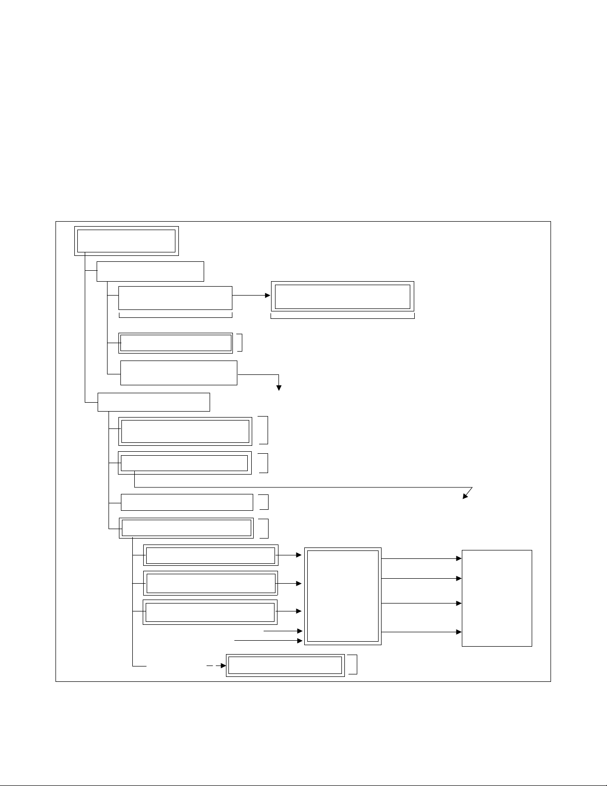
CHAPTER 2 SYSTEM MAINTENANCE OUTLINE
1. GENERAL
1.1 Purpose
This chapter explains the outline of fault diagnosis and duties necessary to maintain the PBX.
1.2 Administrative Management Procedures
Figure 2-1 shows the work flow of the administrative management procedures.
Administrative
Management Procedures
Administrative Procedures
Expansion and Change of
Station Users
See Chapter 6
Traffic Management
Actions on Claims from
Station Users and/or Operators
Management Procedures
Station Message Detail
Recording System (SMDR)
Routine Diagnosis
Diagnosis result, system message displays abnormality
Routine Maintenance
System Status Monitor
Alarm Indications
Collection of System Messages
Indication of Lockout Stations
See Chapter 6
(A)
(B)
Office Data Management and Office
Data Protection
See Chapter 6
(A)
See Chapter 6
See Chapter 6
See Chapter 7
See Chapter 6
Fault Analysis/
Test Operation/
Changeover/
Make-Busy/Circuit
Card Change/
Initialization
Line fault
Circuit card fault
Terminal
(Tel., etc.) fault
Fault cause not
able to be localized
(B)
Refer to
Chapter 5
(Abnormal
Congestion)
Line Load Control
See Chapter 6
Figure 2-1 Flow of Administrative Management Procedures
NDA-24300 CHAPTER 2
Page 3
Issue 1
Page 31

SYSTEM MAINTENANCE OUTLINE
1.3 Summary of This Manual’s Contents
Table 2-1 provides a brief description of the contents for each chapter in this manual.
Table 2-1 Summary of This Manual’s Contents
CHAPTER DESCRIPTION
2See Section 2, Basic Knowledge.
Explains basic knowledge of fault detection and indi cation, functions and fault range of th e system,
etc.
See Section 3, Ho w to Read Pr ecautions, Diagnos tic , and Fault Repair Information.
Explains the methods of procedure performance and various symbols used in the description.
See Section 4, Reporting Fault to NEC.
Explains the method of f orward ing f ault y circ uit cards, the meth od of creating a hist ory recor d for fu-
ture fault repair, and the method of reporting faults to NEC.
3 Explains how to read and analyze system messages.
4 Explains the method of replacing a unit/circuit card due to a fault.
5 Explains repair procedures corresponding to the faults of processors or equipment.
6 Explains how to control the system in service management functions and precautions required in the
system control process.
7 Explains routine maintenance.
8 Explains the commands used in the system administrative management procedure.
2. BASIC KNOWLEDGE
This section identifi es the information nec essary for the system operations and maintenance procedures.
2.1 System Configuration
2.2 Line Equipment Numbers (LENS)
2.3 Local P artition (LP) Numbe r
2.4 System Messages
2.5 Fault Detecting Function
2.6 Range of Faults Specification
2.7 Explanation of Terms
CHAPTER 2 NDA-24300
Page 4
Issue 1
Page 32

SYSTEM MAINTENANCE OUTLINE
2.1 System Configuration
Figure 2-2 sho ws t he sys tem configuration of the f ully e xpanded 4-IMG t ype. F or detai ls on e ach modul e
accommodation, see Figure 2-3 through Figure 2-5.
IMG0
TOPU
PIM3
PIM2
FANU
PIM1
PIM0
LPM
BASEU
BASEU: Base U n i t
DUMMY: Dummy Box
FANU: Fan Unit
LPM: Local Processor Module
PIM: Port Interface Module
TOPU: Top Unit
TSWM: Time Division Switch Module
Figure 2-2 System Configuration
IMG1
TOPU
PIM3
PIM2
FANU
PIM1
PIM0
TSWM
BASEU
FRONT VIEW
IMG2
TOPU
PIM3
PIM2
FANU
PIM1
PIM0
DUMMY
BASEU
IMG3
TOPU
PIM3
PIM2
FANU
PIM1
PIM0
DUMMY
BASEU
NDA-24300 CHAPTER 2
Page 5
Issue 1
Page 33

SYSTEM MAINTENANCE OUTLINE
Figure 2-3 shows the face layout of IMG0.
IMG0
TOPU
00 01 02 03 04 05 06 07 08 09 10 11 12 13 14 15 16 17 18 19 20 21 22 23
PH-PC36 (MUX)
PH-PC36 (MUX)
PWR0
PWR1
PIM 3
00 01 02 03 04 05 06 07 08 09 10 11 12 13 14 15 16 17 18 19 20 21 22 23
PH-PC36 (MUX)
PH-PC36 (MUX)
PWR1
PWR0
PIM 2
FANU
00 01 02 03 04 05 06 07 08 09 10 11 12 13 14 15 16 17 18 19 20 21 22 23
PH-PC36 (MUX)
PWR1
PWR0
PIM 1
Note:
0000010102020303040405 06 07 08 09 10 11 12 13 14 15 16 17 18 19 20 21 22 23
PH-PC36 (MUX) PH-PC36 (MUX)
PWR1
PWR0
PIM 0
PH-PC40 (E MA)
PH-IO24 (IOC)
Note
LPM
BASEU
Front View
The 2nd IOC card (optional) may be mounted in this slot.
Figure 2-3 Face Layout of IMG0
PH-PC36 (MUX)
CHAPTER 2 NDA-24300
Page 6
Issue 1
Page 34

SYSTEM MAINTENANCE OUTLINE
Figure 2-4 shows the face layout of IMG1.
TOPU
00 01 02 03 04 05 06 07 08 09 10 11 12 13 14 15 16 17 18 19 20 21 22 23
PA-PW 55-A (PW R 0)
PA-PW 54-A (PW R 1)
PWR1
PWR0
PIM 3
00 01 02 03 04 05 06 07 08 09 10 11 12 13 14 15 16 17 18 19 20 21 22 23
PA-PW 55-A (PW R 0)
PA-PW 54-A (PW R 1)
PWR0
PWR1
PIM 2
FANU
00 01 02 03 04 05 06 07 08 09 10 11 12 13 14 15 16 17 18 19 20 21 22 23
PWR0
PWR1
PIM 1
IMG1
PH-PC36 (MUX)
PH-PC36 (MUX)
PH-PC36 (MUX)
PH-PC36 (MUX)
PH-PC36 (MUX)
PH-PC36 (MUX)
PH-PC36 (MUX)
0000010102020303040405 06 07 08 09 10 11 12 13 14 15 16 17 18 19 20 212122
PH-PC36 (MUX) PH-PC36 (MUX)
PH-PC36 (MUX)
PWR0
PWR1
PIM 0
TSWM
BASEU
PWRSW0
05 06 07 08 09 10 11 12 13 14 15 16 17 18 19 20
PWRSW1
MISC
MISC
MISC
MISC
MISC
DLKC0
DLKC1
GT0
GT1
TSW01
TSW00
TSW02
TSW03
TSW10
TSW11
PLO0
TSW12
TSW13
Front View
PWRSW: PH-PW14 DLKC: PH-PC20 GT: PH-GT09 TSW: PH-SW12
PLO: PH-CK16/17/16-A/17-A
Note:
No circuit card is mounted in Slot 02 of TSWM. Instead, on the backboard of this slot, a
terminal resistor with a total of two in a dual system is fastened.
Figure 2-4 Face Layout of IMG1
22 23
23
PLO1
NDA-24300 CHAPTER 2
Page 7
Issue 1
Page 35

SYSTEM MAINTENANCE OUTLINE
Figure 2-5 shows the face layout of IMG 2/3.
IMG2/3
TOPU
00 01 02 03 04 05 06 07 08 09 10 11 12 13 14 15 16 17 18 19 20 21 22 23
PH-PC36 (MUX)
PH-PC36 (MUX)
PWR1
PWR0
PIM 3
00 01 02 03 04 05 06 07 08 09 10 11 12 13 14 15 16 17 18 19 20 21 22 23
PH-PC36 (MUX)
PH-PC36 (MUX)
PWR1
PWR0
PIM 2
FANU
PIM 1
PIM 0
DUMMY
00 01 02 03 04 05 06 07 08 09 10 11 12 13 14 15 16 17 18 19 20 2121222223
PH-PC36 (MUX)
PWR1
PWR0
00 01 02 03 04 05 06 07 08 09 10 11 12 13 14 15 16 17 18 19 20 21 22 23
PH-PC36 (MUX) PH-PC36 (MUX)
PH-PC36 (MUX)
PWR1
PWR0
BASEU
Figure 2-5 Face Layout of IMG2/3
CHAPTER 2 NDA-24300
Page 8
Issue 1
Front View
Page 36

SYSTEM MAINTENANCE OUTLINE
2.2 Line Equipment Numbers (LENS)
The Line Equipment Numbers (LENS) are used to specify the location of a circuit (trunk/port) in any of
the PIM universal slots. Refer to the figures in this section, and confirm the LENS format used in the
system.
As shown in Fig ure 2-6, the LENs co nsist s of si x digit s: tw o dig its fo r MG, one digit for U, tw o digi ts fo r
G, and one digi t for Lv.
LENS = XX X XX X
Lv (Level) : 0 - 7
Note:
If an FCH (PA-FCHA) card is used, line gr oups 24-31 can be u sed as the e xtended gr oup numbers.
2.2.1 Module Group
Figure 2-7 explai ns the Module Gr oup (MG). In a full y expande d system, the MG number ranges from
00 to 07.
IMG0
TOPU
PIM3
MG01
PIM2
FANU
G (Group) : 00 - 23
U (Unit) : 0 - 3
MG (Module Group) : 00 - 07
Figure 2-6 LENS Format
IMG1
TOPU
MG03
FANU
MG05
IMG2
TOPU
FANU
Note
IMG3
TOPU
MG07
FANU
PIM1
PIM0
MG00
LPM
BASEU
MG02
TSWM
BASEU
FRONT VIEW
MG04
DUMMY
BASEU
Figure 2-7 Module Group Allocations
NDA-24300 CHAPTER 2
MG06
DUMMY
BASEU
Page 9
Issue 1
Page 37

SYSTEM MAINTENANCE OUTLINE
2.2.2 Unit
Figure 2-8, which represents a fully expanded system, explains the Unit (U) numbers. The numbers
range from 0 to 3, a nd each u nit r epres ents th e PI M universal sl ots, No. 04-12 ( U 0/2) or No. 15-23 (U
1/3).
On each Module Group (MG: #00 - 07), a total of four Units (U0 - U3) can be assigned.
PIM3
PIM2
PIM1
PIM0
Slots No.
IMG0
TOPU
U2
U3
MG01
U0
U2
FANU
U1
U3
MG00
U0
BASEU
U1
LPM
Unit Number (U = 0/2) Unit Number (U = 1/3)
00 02 04 05 06 07 08 09 10 11 12 13 14 15 16 17 18 19 20 21 22 23
IMG1
TOPU
U2
MG03
U0
U2
MG02
U0
TSWM
BASEU
U3
U1
FANU
U3
U1
FRONT VIEW
U2
MG05
U0
FANU
U2
MG04
U0
DUMMY
BASEU
IMG2
TOPU
U3
U1
U3
U1
U2
MG07
U0
U2
MG06
U0
DUMMY
BASEU
IMG3
TOPU
U3
U1
FANU
U3
U1
PWR
PWR
Number
of
Time Slots
(16)(16)
16 16 16 16 16 16
Control Control
Figure 2-8 Unit Number Allocations
CHAPTER 2 NDA-24300
Page 10
Issue 1
MUX (PH-PC36) 0
MUX (PH-PC36) 1
192 TS192 TS
PIM
16 16 16 16 16 16 32 32 3216 16 16 16 16 16 32 32 32
Page 38

SYSTEM MAINTENANCE OUTLINE
2.2.3 Group
The Group (G) numbers are allocated as shown in Figure 2-9. A total of two Groups are assigned on
each universal slots within the PIM. Slot numbers 10, 11, 12, 21, 22, 23 can contain a total of four
Groups as an exception.
A total of two or four Groups (G) can be assig ned on eac h PIM uni ve rsal s lot.
PIM3
PIM2
PIM1
PIM0
IMG0
TOPU
U2
U3
MG01
U0
U2
U0
U1
FANU
U3
MG00
U1
LPM
BASEU
00 02 04 05 06 07 08 09 10 11 12 13 14 15 16 17 18 19 20 21 22 23
PWR
PWR
IMG1
TOPU
U2
MG03
U0
U2
MG02
U0
TSWM
BASEU
U3
U1
FANU
U3
U1
U2
U0
U2
U0
MUX (PH -P C 36) 0
IMG2
TOPU
MG05
FANU
MG04
DUMMY
BASEU
MUX (PH -P C 36) 1
U3
U1
U3
U1
PIM
FRONT VIEW
U2
U0
U2
U0
DUMMY
IMG3
TOPU
MG07
FANU
MG06
BASEU
U3
U1
U3
U1
G = 03
G = 02
Slot No. 05
Slot No. 10
G = 15
16 ports total
G = 14
32 ports total
G = 13
Note:
G = 12
11
10
14
13
12
19
18
17
16
22
20
PIM
21
Group No.
Slot No.
Extended
Group No.
Note
01
00(25)(24)
27 29 31
26 28 30
04 05 06 07 08 09 10 11 12 13 14 15 16 17 18 19 20 21 22 23 00 02
030205040706090811
10
15
14
13
12
19
18
17
16
23
22
21
20
010003020504070609
08
27 29 31
26 28 30
23
15
U = 0 / 2 U = 1 / 3
In addition to Group No. 00 - 23, the system can use No. 24 - 31 as theoretically valid numbers.
Figure 2-9 Group Number Allocations
NDA-24300 CHAPTER 2
Page 11
Issue 1
Page 39

SYSTEM MAINTENANCE OUTLINE
2.2.4 Level
Figure 2-10 explains the Level (Lv) numbers. There are a total of eight Levels (Lv0 - Lv7) on every
Group number, which ranges from 00 to 31.
A total of eight Levels (Lv0 - Lv7) c an be ass i gned on each Group.
PIM3
PIM2
PIM1
PIM0
U2
MG01
U0
U2
MG00
U0
BASEU
IMG0
TOPU
FANU
LPM
U3
U1
U3
U1
IMG1
TOPU
U2
MG03
U0
FANU
U2
MG02
U0
TSWM
BASEU
U3
U1
U3
U1
FRONT VIEW
IMG2
TOPU
U2
MG05
U0
FANU
U2
MG04
U0
DUMMY
BASEU
U3
U1
U3
U1
U2
MG07
U0
U2
MG06
U0
DUMMY
BASEU
IMG3
TOPU
FANU
U3
U1
U3
U1
Group
(G = Odd No., < 11)
Group
(G = Even No., < 10)
Group No.
Level (Lv)
7
6
5
4
3
2
1
0
7
6
5
4
3
2
1
0
U = 0 / 2
00 02 04 05 06 07 08 09 10 11 12 13 14
0100030205040706090811
(24) (25)
2726292831
15
19
23
14
18
22
13
17
21
10
12
16
20
30
16-port Slot
U = 1 / 3
15 16 17 18 19 20 21 22 23
0100030205040706090811
2726292831
15
19
14
18
13
17
10
12
16
30
32-port Slot
23
22
PIM
21
20
Level (Lv)
7
6
5
4
3
Group
(G = 15/19/23)
2
1
0
7
6
5
4
3
Group
(G = 14/18/22)
2
1
0
7
6
5
4
3
Group
(G = 13/17/21)
2
1
0
7
6
5
4
3
Group
(G = 12/16/20)
2
1
0
Figure 2-10 Level Number Allocations
CHAPTER 2 NDA-24300
Page 12
Issue 1
Page 40

SYSTEM MAINTENANCE OUTLINE
2.3 Local Partition (LP) Number
The Local Partition (LP) number refers to a logical local processor number, theoretically assigned for each
IMG that consists of four (or less) Port Interface Modules (PIM). Though the local processor does not
actually e xist in any of the IM Gs, ex cept for IMG0, the system can apply the tw o-digit LP number to each
IMG (see Figure 2-11) on its da ta memory program. The LP numbers are used primarily i n t he following
cases:
• Display of system messages
• Assignment of line load control data (ALLC command)
• Backup for Call Forwarding/Speed Calling data (MEM_HDD command), etc.
The Local Partition No. (two digits, even number) is assigned on each IMG.
IMG0
TOPU
PIM3
PIM2
FANU
PIM1
PIM0
LPM
BASEU
LP No. = 00 LP No. = 02 LP No. = 04 LP No. = 06
IMG1
TOPU
PIM3
PIM2
FANU
PIM1
PIM0
TSWM
BASEU
FRONT VIEW
IMG2
TOPU
PIM3
PIM2
FANU
PIM1
PIM0
DUMMY
BASEU
IMG3
TOPU
PIM3
PIM2
FANU
PIM1
PIM0
DUMMY
BASEU
Figure 2-11 LP Number Allocations
NDA-24300 CHAPTER 2
Page 13
Issue 1
Page 41

SYSTEM MAINTENANCE OUTLINE
2.4 System Messages
System messages display during routine diagnosis, system operation status controlling, and fault
occurrence. Figure 2- 12 shows an example of a system message.
Refer to Chapter 3 for details on each message.
(1) SYSTEM MESSAGE 3-E SUP LOCK UP FAILURE (TEMPORARY)
(2) NEC TOKYO JUL 24 09:35
(3) LP00-0-ACT
(4)
Meaning:
1:1102 0000 0000 0000 2:0000 0000 0000 0000 3:0000 0000 0000 0000
4:0000 0000 0000 0000 5:0000 0000 0000 0000 6:0000 0000 0000 0000
7:0000 0000 0000 0000 8:0000 0000 0000 0000 9:0000 0000 0000 0000
(1) : SYSTEM MESSAGE 3-E SUP LOCK-UP FAILURE (TEMPORARY)
Meaning of the message
System Message Level
(Indicated by Alarm Lamp) Note
System Message Number
Note:
There ar e four kin ds of alarm information to be indicated by alarm lamps : MN,
MJ, SUP, and No Indication.
(2) : Office Name, Date and Time
(3) : LP00-0-ACT
ACT/STBY indication for dual systems
No.0/No.1 system indication for dual systems
Faulty processor/Related processor
(4) : Message detail data (notation by hexadecimal numbers)
Figure 2-12 System Message Example
CHAPTER 2 NDA-24300
Page 14
Issue 1
Page 42

SYSTEM MAINTENANCE OUTLINE
2.5 Fault Detecting Function
The system fin ds a f ault b y its f aul t dete cting c ircui t and th e f aul t detec ting progr am. Once a fa ult occ urs,
the system initiates a remedial action such as system changeover, make-busy setting, or restart processing
by the automatic di agnosis func tion. This ac tion reduces the influe nce of the f ault so t hat system ser vicing
may be minimized. The result of the process taken and the fault situation are indicated for equipment
concerned.
Among the faults, those related to speech path (noise , one-way speech, sp eech inability, etc.) are not
detectable. Since t hese f ault r eports a re to be obtaine d from a s tation o r operator, periodic trunk tests must
be performed without failure to detect the faults related to speech path.
Figure 2-13 show s an out line of fault detecti on, and Figure 2-14 shows a block di agram of f ault det ection.
Fault Occurrence
Indication
Display of
System Messages
Indication of
Alarm Lamps
on TOPU
NEC
Information
Collection and Diagnosis
Example of Faults
IOC
Fault of line/trunk card
CPU
NEAX 2400 IMS
EMA
TSW write failure,
Fault of cloc ks , etc.
Abnormal temperature,
power supply failure ,
fuse blowing, etc., within
the equipment frame
Figure 2-13 Fault Detection General Diagram
NDA-24300 CHAPTER 2
Page 15
Issue 1
Page 43

SYSTEM MAINTENANCE OUTLINE
Alarm Lamps on TOPU
Symbols
To MAT,
Printer, etc.
: Circuit Card
: Main faults to be detected
: Speech path
: Flow of fault information
IOC
CPU
Firmware
Fault
C-level
monitor
RDY
Clock
etc.
TSWM
Howler
Ringing
Circuit
GT
RDY
Clock
Write
etc.
Ready
Thermal Reed Relay
LC/TRK
MUX
TSW/INT
DLKC
PWR
Note:
MJ, MN fault
Power, Fuse blown fault
Fault
Information
Note
Temperature, CPU fault
Speech Path System fault (SPE)
RGU, Howler fault
PFT fault
CPU Clock fault
SYMBOL NAME SYMBOL NAME
CPU
EMA
IOC
LC/TRK
GT
PWR
Central Processing Unit
Emergency Alarm Controller
I/O Controller
Line/Trunk
Gate
Power Supply
Figure 2-14 Fault Detection Block Diagram
CHAPTER 2 NDA-24300
Page 16
Issue 1
DLKC
TSW
TSWM
INT
MUX
PWR Supply
Failure,
Fuse Blown
EMA
Data Link Controller
Speech Path Control Interface
Time Division S w itch
Multiplexer
Time Division Switch Module
Page 44

SYSTEM MAINTENANCE OUTLINE
(a) Main Faults
Faults that may o ccur in the syst em can be general ly categor ized into Processo r System F ault, Speech
Path System Fault, Line/Trunk Fault, etc.
• Processor System Fault
The CPU alarm detecting circuit contin uously monitors whether the CPU is working normally. If
a fault is detected, the CPU calls up the diagnostic program, which identifies the cause of the fault
and determines whether the fault is temporary or permanent. When the fault affects system
operations, Active/Standby status of the CPU is changed over (provided that the system has dual
configuration).
• Bus System Fault
The CPU transfers line/trunk card control information to the associated peripheral circuits via IO
Bus. When a parity error is detected in the transfer data or when the required information cannot
be transferred from a circuit card, the CPU identifies the cause of the fault, changes over the CPU
so that system operation is not affected, and executes restart processing.
• Speech Path Fault
The CPU monitors the operating status of the TSW card, the occurrence of errors in writing data
to the switch memory, and the basic clocks suppli ed to the s peech path . Upon detect ing a f ault, th e
CPU identifies the cause of the fault, determines whether the fault is temporary or permanent, and
executes required processing such as changeover of the TSW card.
•Others
The alarm detecting circui t on the EMA card con tinuousl y monitors the occ urrence of fa ults in the
PWR supply cards, such as abnormal temperatures within the equipment frame, and lights the
alarm lamp on the TOPU when a fault is detected.
(b) Lamp Indications on the TOPU
When a fault occurs, the corr esponding lamp on the T OPU indicate s the locati on of the f ault. F or the
meaning of each lamp indication, refer to Chapter 6.
NDA-24300 CHAPTER 2
Page 17
Issue 1
Page 45

SYSTEM MAINTENANCE OUTLINE
2.6 Rang e of Faults Specification
(1) Upon receiving a fault report from a station user or an operator, the technician can assume a faulty card
exists if the ran ge to be af fected by the fault ca n be determin ed. Fo r the detail ed procedure , refer to Chap-
ter 5. Use the fo llowing actions to check the MDF:
(a) Check the LENS of the reporter (Station or ATTCON/DESKCON).
(b) Check other circuits of the circuit card in which the reporter (station line or ATTCON/DESKCON)
is located.
(c) Check the ot her gr oups ( other circ uit c ards mou nted i n the sa me module) in t he mo dule in which the
reporter is located.
(d) Check lines in each of the other modules on the basis of plural lines.
(2) If the fault cannot be dete cted by the system (a f ault relate d to the speech path s uch as noise duri ng speech,
one-way speech, speech inability), the range of (a) through (d) (itemized above) should be limited.
(3) Wh e n a ma jo r faul t is det e cted i n the du al sys te ms , the C PU or TS W sy st em auto m ati c al ly ch ang es over
if the fault ra nge is (c) an d (d). In th is case, the w hole modul e involved is placed into m ake-busy sta tus
even if the fault is partial, and the station lines currently operating normally become faulty status.
Diagnose the fault from the content of the system message displayed and repair the fault as required.
(4) When limiting the range of faults, consider the system circuitry that consists of the control (see Figur e 2-
16, where CPU 0 is active) and speech path syst ems (se e Figure 2-17).
(5) As seen from the block diagrams in Figure 2-15 through Figure 2-18, if a fault occurs within the common
portions to be controlled, all other associated portions are affected by that fault occurrence. If the range
of faults is outside PIM fault, CPU/TSW system changeover is executed (only when the fault is detectable
by the system).
CHAPTER 2 NDA-24300
Page 18
Issue 1
Page 46

SYSTEM MAINTENANCE OUTLINE
E1/DS1
with
Fusion Link
IMG0
PM BUS
LC/TRK LC/TRK
PM BUS
LC/TRK LC/TRK
PM BUS
LC/TRK LC/TRK
PM BUS
FCH LC/TRK
DTI
MUX
MUX
MUX
MUX
SERIAL BUS
TSWM
TSW 00
To MUX
TSW 01
To MUX (IMG2)
T
S
W
I
/
O
B
U
S
0
TSW 02
To MUX (IMG3)
TSW 03
PLO 0
MISC I/O BUS MISC I/O BUS
DLKC 0 DLKC 1
TSW 10
To MUX
TSW 11
To MUX (IMG2)
TSW 12
To MUX (IMG3)
TSW 13
MISC
PLO 1
T
S
W
I
/
O
B
U
S
0
MUX
MUX
MUX
MUX
PM BUS
LC/TRK LC/TRK
PM BUS
LC/TRK LC/TRK
PM BUS
LC/TRK LC/TRK
PM BUS
LC/TRK
FCH
DTI
E1/DS1
with
Fusion Link
Symbols
: Circuit Card
GT 1GT 0
G
T
B
LPM
HUB HUB
10 BASE-T 10 BASE-T
EMA: PH-PC40 ISAGT: PZ-GT13 LANI: PZ-PC19 GT: PH-GT09 IOC: PH-IO24
TSW: PH-SW12 DLKC: PH-PC20 M UX: PH-PC36 PLO: PH-CK16/17/16-A/17-A
U
S
ISAGT
CPU 0
LANI LANI
MISC I/O BUS
EMA
01
MISC
IOC
RS-232C
MAT
10 BASE-T
HUB
G
T
B
U
S
ISAGT
CPU 1
LANI LANI
MATAP
Figure 2-15 General System Block Diagram
NDA-24300 CHAPTER 2
Page 19
Issue 1
Page 47

SYSTEM MAINTENANCE OUTLINE
PIM 3
PIM 2
PIM 1
PIM 0
MUX
MUX
MUX
MUX
IMG0
LC/TRK
LC/TRK
LC/TRK
LC/TRK
PM BUS
PM BUS
PM BUS
PM BUS
PM BUS
PM BUS
PM BUS
PM BUS
LC/TRK
LC/TRK
LC/TRK
LC/TRK
MUX
MUX
MUX
MUX
TSWM
PIM 3
PIM 2
PIM 1
PIM 0
M
M
M
M
M
U
U
X
X
003
002
TSW/INT TSW/INT TSW/INTTSW/INT
M
U
U
U
U
X
X
X
X
001
000
013
012
MUX
MUX
MUX
MUX
TSW
M
M
/INT
U
U
X
X
011
010
TSW
02
TSW
/INT
TSW
03
IMG1
LC/TRK
LC/TRK
LC/TRK
LC/TRK
PM BUS
PM BUS
PM BUS
PM BUS
PM BUS
PM BUS
PM BUS
PM BUS
M
M
M
U
U
U
X
X
X
100
101
102
LC/TRK
LC/TRK
LC/TRK
LC/TRK
M
U
X
103
MUX
MUX
MUX
MUX
To IMG 2To IMG 3 To IMG 3To IMG 2
TSW
TSW
M
M
M
M
U
U
U
U
X
X
X
X
110
111
112
113
/INT
/INT
TSW
TSW
13
12
TSW 00 TSW 10 TSW 11TSW 01
TSW I/O
DLKC 1
DLKC 1
MISC BUS
BUS
LPM
CPR
CPU clock
PCI BUS
LANI
Note 2
ISAGT 0
CPU 0
MEMORY
T
M
ISA BUS
CPU board
Reset Signal
PWR
MISC BUS
EMA
PWR
IOC /
MISC
MISC BUS
IOP1
Note 3
IOP0
CPR
(ST-BY)
ISAGT 1
GT 0
GT 1
BUS
TSW I/O
MISC BUS
MISC BUS
DLKC 0
MISC BUS
MISC BUS
Note 1
MISC BUS
PLO 0 PLO 1
Symbols
: Controlling Routes of CPU : Cable
: Circuit card (active) : Circuit card (STBY)
: External Cable : Clock Oscillator
: Signral
T
EMA: PH-PC40 ISAGT: PZ-GT13
LANI: PZ-PC19 GT: PH-GT09
IOC: PH-IO24 TSW: PH-SW12
DLKC: PH-PC20 PLO: PH-CK16/17/16-A/17-A
MUX: PH-PC36
Note 1: The circuit cards, drawn by dotted lines, indicate they are in STBY state. These cards (TSW, MUX and
DLKC) are totally changed over to the ACT mode, when the MBR key of the active GT (PH-GT09) card is
once flipped. However, PLO (PH-CK16/17/16-A/17-A) is independent and not affected by the development.
Note 2: If the ACT/STBY of CPU is once changed over, the system of GT (in TSWM) also changes over.
Note 3: Though an external cable is physically connected between ISAGT0 and GT1, the actual control signal is
sent/received only between ISAGT0 and GT0. This is because GT0 and GT1 are having a multiple connection
on the backboard side. (Refer to Chapter 6, Section 12.)
Figure 2-16 CPU Controlling Block Diagram
CHAPTER 2 NDA-24300
Page 20
Issue 1
Page 48

SYSTEM MAINTENANCE OUTLINE
PIM 3
PIM 2
PIM 1
PIM 0
MUX
MUX
MUX
MUX
IMG2
LC/TRK
LC/TRK
LC/TRK
LC/TRK
PM BUS
PM BUS
PM BUS
PM BUS
PM BUS
PM BUS
PM BUS
PM BUS
LC/TRK
LC/TRK
LC/TRK
LC/TRK
MUX
MUX
MUX
MUX
PIM 3
PIM 2
PIM 1
PIM 0
MUX
MUX
MUX
MUX
IMG3
LC/TRK
LC/TRK
LC/TRK
LC/TRK
PM BUS
PM BUS
PM BUS
PM BUS
PM BUS
PM BUS
PM BUS
PM BUS
LC/TRK
MUX
LC/TRK
MUX
LC/TRK
MUX
LC/TRK
MUX
To IMG 0To IMG 1 To IMG 1To IMG 0
TSWM
M
M
M
M
U
U
U
U
X
X
X
X
023
022
021
020
TSW/INT TSW/INT TSW/INTTSW/INT
TSW
/INT
TSW
00
TSW
/INT
TSW
01
M
M
M
M
M
M
M
U
U
U
U
X
X
X
X
120
121
122
123
M
U
U
U
U
X
X
X
X
130
131
132
133
M
M
M
M
U
U
U
U
X
X
X
X
033
032
031
030
TSW
/INT
TSW
10
TSW
/INT
TSW
11
TSW 02 TSW 12 TSW 13TSW 03
BUS
TSW I/O
MISC BUS
DLKC 1
DLKC 1
MISC BUS
LPM
CPR
CPU clock
PCI BUS
LANI
Note 2
ISAGT 0
ISA BUS
CPU 0
MEMORY
CPU board
TSW I/O
MISC BUS
BUS
DLKC 0
IOP1
GT 0
Note 3
T
M
MISC BUS
Reset Signal
PWR
EMA
IOC /
MISC
MISC BUS
PWR
IOP0
CPR
(ST-BY)
ISAGT 1
GT 1
T
MISC BUS
MISC BUS
Note 1
MISC BUS
PLO 0 PLO 1
Symbols
: Controlling Routes of CPU : Cable
: Circuit card (active) : Circuit card (STBY)
: External Cable : Clock Oscillator
: Signral
EMA: PH-PC40 ISAGT: PZ-GT13
LANI: PZ-PC19 GT: PH-GT09
IOC: PH-IO24 TSW: PH-SW12
DLKC: PH-PC20 PLO: PH-CK16/17/16-A/17-A
MUX: PH-PC36
Note 1: The circuit cards, drawn by dotted lines, indicate they are in STBY state. These cards (TSW, MUX and
DLKC) are totally changed over to the ACT mode, when the MBR key of the active GT (PH-GT09) card is
once flipped. However, PLO (PH-CK16/17/16-A/17-A) is independent and not affected by the development.
Note 2: If the ACT/STBY of CPU is once changed over, the system of GT (in TSWM) also changes over.
Note 3: Though an external cable is physically connected between ISAGT0 and GT1, the actual control signal is
sent/received only between ISAGT0 and GT0. This is because GT0 and GT1 are having a multiple connection
on the backboard side. (Refer to Chapter 6, Section 12.)
Figure 2-16 CPU Controlling Block Diagram (Continued)
NDA-24300 CHAPTER 2
Page 21
Issue 1
Page 49

SYSTEM MAINTENANCE OUTLINE
PIM 3
PIM 2
PIM 1
PIM 0
MUX
MUX
MUX
MUX
LC/TRK
LC/TRK
LC/TRK
LC/TRK
IMG0
LC/TRK LC/TRK
LC/TRK LC/TRK
LC/TRK LC/TRK
LC/TRK LC/TRK
MUX
MUX
MUX
MUX
PIM 3
PIM 2
PIM 1
PIM 0
MUX
MUX
MUX
MUX
LC/TRK
LC/TRK
LC/TRK
LC/TRK
IMG1
MUX
LC/TRK LC/T RK
MUX
LC/TRK LC/T RK
MUX
LC/TRK LC/T RK
MUX
LC/TRK LC/T RK
LVDS (Low Voltage Differential Signaling)
TSWM
TSW 00
MUX 003
MUX 002
MUX 001
MUX 000
TSW/INT
TSW 10
MUX 100
MUX 101
MUX 102
MUX 103
TSW/INT
Symbols
: Speech Path
: Circuit Card (active)
Figure 2-17 Speech Path Block Diagram
TSW 01
MUX 013
MUX 012
MUX 011
MUX 010
TSW/INT
TSW 11
MUX 110
MUX 111
MUX 112
MUX 113
TSW/INT
: Cable
: Circuit Card (STBY)
To IMG2
To IMG2
TSW/
TSW/
INT
INT
TSW
TSW
02
12
TSW: PH-SW12
MUX: PH-PC36
To IMG3
TSW/
INT
TSW
03
To IMG3
TSW/
INT
TSW
13
CHAPTER 2 NDA-24300
Page 22
Issue 1
Page 50

SYSTEM MAINTENANCE OUTLINE
PIM 3
PIM 2
PIM 1
PIM 0
MUX
MUX
MUX
MUX
LC/TRK
LC/TRK
LC/TRK
LC/TRK
IMG2
LC/TRK LC/TRK
LC/TRK LC/TRK
LC/TRK LC/TRK
LC/TRK LC/TRK
MUX
MUX
MUX
MUX
PIM 3
PIM 2
PIM 1
PIM 0
MUX
MUX
MUX
MUX
LC/TRK
LC/TRK
LC/TRK
LC/TRK
IMG3
MUX
LC/TRK LC/T RK
MUX
LC/TRK LC/T RK
MUX
LC/TRK LC/T RK
MUX
LC/TRK LC/T RK
LVDS (Low Voltage Differential Signaling)
TSWM
TSW 02
MUX 023
MUX 022
MUX 021
MUX 020
TSW/INT
TSW 12
MUX 120
MUX 121
MUX 122
MUX 123
TSW/INT
Symbols
: Speech Path
: Circuit Card (Active)
Figure 2-17 Speech Path Block Diagram (Continued)
TSW 03
MUX 033
MUX 032
MUX 031
MUX 030
TSW/INT
TSW 13
MUX 130
MUX 131
MUX 132
MUX 133
TSW/INT
: Cable
: Circuit Card (STBY)
To IMG0
To IMG0
TSW/
TSW/
INT
INT
TSW
TSW
00
TSW: PH-SW12
MUX: PH-PC36
10
To IMG1
TSW/
INT
TSW
01
To IMG1
TSW/
INT
TSW
11
NDA-24300 CHAPTER 2
Page 23
Issue 1
Page 51

SYSTEM MAINTENANCE OUTLINE
A fault within this range affects two sl ots.
PIM 3
PIM 2
PIM 1
LC/TRK
LC/TRK
A fault within this range
affects the circuit card.
LC/TRK
LC/TRK
A fault within this range
affects the circuit card.
LC/TRK
LC/TRK
32ch
32ch
32ch
MUX
A fault within this range
affects two slots.
MUX
A fault within this range
affects two slots.
MUX
A fault within this range
affects this module.
512ch
A fault within this range
affects this module.
512ch
A fault within this range
affects this module.
512ch
PIM 0
Symbols
A fault within this range
affects the circuit card.
A fault within this range
affects two slots.
LC/TRK
LC/TRK
A fault within this range
affects the circuit card.
TSW
: Circuit Card : Possible fault range to be affected : Speech Path
32ch
MUX
TSW/INT
A fault within this range
affects this module.
512ch
Figure 2-18 Speech Path Range of Fault
CHAPTER 2 NDA-24300
Page 24
Issue 1
Page 52

2.7 Explanation of Terms
• C-Level Infinite Lo o p
The program repeatedly e xecutes speci fic routines due to a fault of the main memory , data des truction,
etc. The program is not a ble to b e proces se d normall y. This faulty condition is re ferr ed to as Program
Infinite Loop. C-Level infinite loop is a state where a clock-level program, which runs under clock
interrupt disable state, is in an infi nite loop status.
• B-Level Infinite Lo o p
This is a state where a program infinite loop has occurred during a connection processing and the
connection for the ne xt call is not able to be processed.
• Port Microprocessor (PM)
Each line/trunk card mounted in the PIM is equipped with a processor called Port Microprocessor
(PM), which continuously supervi se s the lines /t runks.
• Ready Error
For acknowledging the connection between the CPU and a circuit card, an interface signal called
Ready Signal is used. When the CPU has accessed a specific circuit card and the normality of the
connection is ac kno wledged, th e Ready S ignal is returne d to the CPU wi thin 6 µs. If the Ready signa l
is not returne d to the CPU within 6 µs after access, the situation is referred to as Ready Error.
SYSTEM MAINTENANCE OUTLINE
• Parity Error
For confirming the normality of data transfer between the CPU and the circuit card under the control
of the CPU, parity check is made. When an error is detected in a parity check, it is referred to as Parity
Error. Parity check means to confirm the normality of data by adding an error detecting parity bit to
a set of data to be transferred.
When a set of data is transferred , a parity bit is added to the data so that the data has an even-number
of “1” bits (it is referred to as Even Parity). When there is an odd-number of “1” bits in the received
one set of data, it is detected as an error.
• Monitor Restart
Monitor restart processing suspends current processings in progress without applying any hardware
controlling, allowing the system to restart its operations from th e monitor program.
The system abandons only the processings of the calls being handled by the program, and maintains
all the connections that have already been established.
• Circuit Card Front Initializing Restart
The whole system is forcibly initialized. However, the initialization varies with the setting of the
SENSE switch on the DSP of CPU (see Table 2-2).
NDA-24300 CHAPTER 2
Page 25
Issue 1
Page 53

SYSTEM MAINTENANCE OUTLINE
Table 2-2 Kinds of Circuit Card Front Restart
SENSE (0~F) KIND OF RESTART REMARKS
1 DM C lear Restart
2 DM Load Restart When the system is in operation
5 OAI Memory Clear Restart
C OFF-line Restart
• PM (Line/Trunk Card) Make-Busy Restart
In this processing, the fault y PM (Line/Trunk Card) is isolated from the system and, at the same ti me,
the calls associated with that faulty PM (Line/Trunk Card) are released. No calls related to the faulty
PM (Line/T runk Card) are processed and t he system normal ly runs without the faulty PM (Line/T runk
Card).
• Data Copy Restart
In a system of dual CPU conf iguration, t he RAM memory (including th e data memory) is copi ed from
the ACT side CPU into the STBY side CPU, and ACT/STBY is changed over and monitor restart is
executed.
In the case of this restart processing, only the ACT side CPU and the STBY side CPU are changed
over without any effect on the current connections. However, no call processings are executed while
the restart processing is in progress (from copying until the end of the changeover).
3. HOW TO READ PRECAUTIONS, DIAGNOSTIC, AND FAULT REPAIR INFORMATION
3.1 Precaution about Diagnostic Procedure/Fault Repair Procedure
When performi ng diagnostic p rocedures/fau lt repair procedures, always adhere to the following actions:
(1) W hen replacing a circuit card with a spare, h andle the circuit card usi ng the Field Servic e Kit.
(a) To protect the circuit card from static electricity, wear a wrist strap before handling the circuit ca rd.
(b) B efore extractin g th e ci rcuit card from its mounting slot, set its MB s witch to the UP side (ON).
(2) When holding a circuit card by hand, wear glov es and be careful not to touch mounted pa r ts , go ld-plated
terminal, etc., on the circuit card.
The 3M
Model 8012 Portable Field Service Kit, shown in Figure 2-19, is recommended as an effective
countermeasure against static electricity.
CHAPTER 2 NDA-24300
Page 26
Issue 1
Page 54

SYSTEM MAINTENANCE OUTLINE
Connect ground wire to the Earth
terminal of the Module Group.
Place the Circuit
Card on a
conductive sheet.
Note:
Wrist Strap
3M is a registered trademark of Minnesota Mining and Manufacturing, Inc.
Figure 2-19 3M
Circuit Card
8
7
6
5
4
4
3
3
2
2
1
OFF
1
OFF
8
7
6
8
5
7
4
6
3
5
2
4
1
OFF
3
2
1
OFF
Plastic Bag
8
7
6
5
4
3
2
1
OFF
4
3
2
1
OFF
®
Model 8012 Portable Field Service Kit
Gold Plated Terminal
7
4
2
3
8
4
1
2
3
6
1
5
OFF
OFF
4
2
3
7
8
5
6
1
OFF
4
2
3
7
8
5
6
1
OFF
4
2
7
3
8
5
6
1
OFF
Circuit Card
Note
Card Puller Tab
Note:
Do not touch the Gold-Plated Terminal with bare hands.
Figure 2-20 How to Hold a Circuit Card
NDA-24300 CHAPTER 2
Page 27
Issue 1
Page 55

SYSTEM MAINTENANCE OUTLINE
(3) When a circuit card appears to be faulty, check the following items before replacing it with a spare:
(a) Poor connector contact at the circuit card may be responsible for the fault. Repeat insertion and ex-
traction of the circuit card a few times. Clean the connector portion, and reche ck for proper operation.
(b) C hec k th e le ad w i res o f vert ic al ly- m oun t ed pa rts ( resi s to rs , ca pa cit or s , e tc. ) to ensu re th ey have not
shorted each other or broken.
(c) Check t he back side o f the c ircui t car d to se e i f there i s an y short -cir cuite d solde red por tion, or mod-
ified cross connect ion wires erroneously left unconnected.
(d) Check the ROMs to ensure proper seating in the IC socket. Figure 2-21 shows a leg th at is be nt an d
not set in the socket.
A pin is bent, not
inserted in the socket.
ROM
SOCKET
Figure 2-21 How to Set the ROM in IC Socket
CHAPTER 2 NDA-24300
Page 28
Issue 1
Page 56

SYSTEM MAINTENANCE OUTLINE
(4) How to clean the connector portion (gold-pl ated terminal):
(a) Dip th e gold-plated terminal port ion in the clea ning fluid for 3 to 5 seconds (on ly PA-XX type circuit
card), as sh own i n Figure 2-22.
Cleaning
Fluid
Circuit
Card
Figure 2-22 How to Clean the Connector Portion
Container
Note 1:
Some of the parts are subject to damage if they come in contact with the cleansing liquid. Be careful
to allow only the connector portion (gold-plated terminal) to contact the cleaning liquid.
Note 2:
Be sure to use fresh cleaning fluid (FREON or isopropyl alcohol).
(b) Using a soft cotton cloth, wipe both s ides of the connector po rtion (gol d-plate d terminal) clean (onl y
PA-XX type circuit card), as shown in Figure 2-23.
gauze
Gold-plated terminal
Figure 2-23 How to Clean Gold-Pl at ed Terminal
Note 1:
Note 2:
Use cloth (gauze, etc.) to clean.
After wiping, be careful not to leave lint on the surface of the circuit card.
(5) When a check on the flat cable or LT cable is directed in the tree, check the following items:
(a) Make a visual check to see if the connector is properly connected.
(b) Poor connector contact may be responsible for the faul t. Repeat connection and disconne ction a fe w
times, and check again to see if the connector is properly connected.
(c) Perform continuity test on the flat cable.
(6) When replacing the circuit card is directed in the tree, replace the circuit card with a spare as per Chapter 4.
(7) When multiple circuit cards a ppear to be faulty, before replacing them with spares, remount them (one at
a time) into their slots , to determine which cards should be replaced.
NDA-24300 CHAPTER 2
Page 29
Issue 1
Page 57

SYSTEM MAINTENANCE OUTLINE
• The following is an e xample where the fault was recovered after the replacement of circuit cards:
START
Set the 1st circuit card back into its mounting slot
If the fault recurs: Replace the circuit card .
Set the 2nd circuit card back into its mounting slot
If the fault recurs: Replace the circuit card .
Set the 3rd circuit card back into its mounting slot
If the fault recurs: Replace the circuit card .
If a circuit card is found to be faulty, send the faulty circuit card for repair.
The fault may be a temporary one, or due to poor contact of the circuit card. Observe the
situation fo r a while.
END
(8) When a fault recovery is completed, use the RALM command to clear all the alarm indications and
registered sys tem messages. If r equired, rest ore temporary cros s connections and transient data for testi ng
to the origi nal ones.
3.2 How to Follow Diagnostic Procedure/Fault Repair Procedure
(a) Diagnostic Work
A fault diagnost ic pro ced ure by syste m messa ge is e xplai ned in the “TREE” f ormat o n an in dividual
system message basis.
• Proceed with judgment as to whether the fault status coincides with the indicated status, following
the sequence beginning from START.
• How to proceed with the diagnosis work is explained in Figure 2-24.
STEP 1 Determine whether the fault coincides with the fault status (1) in Figure 2-24.
STEP 2 If the fault status does coincide, t he fault is indica ted by (2) . Repair the fault by r eferri ng to the
relevant section in Chapter 5. Otherwise, pro cee d to (3).
STEP 3 Perform the work indicated by (3). The result of the work (3) is broken down as indicated by
(4).
STEP 4 Determine whether the result of work (3) coincides with the status indicated by (5). If so, the
fault(s) is/are indicated either by (6) or by (7). If not, proceed to the next Step.
CHAPTER 2 NDA-24300
Page 30
Issue 1
Page 58

SYSTEM MAINTENANCE OUTLINE
STEP 5 Perform the work indicated by (8), and if the result of the work is the same as the status indi-
cated, the fault is indicated by (9). If the fault repair work indicated by (9) affects another normal line, recheck the work as indicated by (10).
(b) Fault Repair Procedure
A fault repair procedure is explained by means of “TREE” format in Chapter 5. The following ex-
plains how to follow the “TREE” format and proceed with designated work. See Figure 2-25.
• Begin from START and proceed with the necessary repair work following the sequence.
• When a faulty circuit ca rd (or circuit cards) is suspect ed, replace the f aulty circu it card with a spar e
in accorda nc e with the work p r ocedure pertaining to that specific circuit card.
STEP 1 Replace the circuit card indicated by (A) with a spare and check it. Perform the detailed work
as per (B). If the fault status is beyond repair, proceed to the next step.
STEP 2 If the range of the fault or the system configuration is as indicated by (C), perform a check as
indicated by (D). If the fault status is beyond repair, proceed to the next step.
STEP 3 Replace the circuit card indicated by (E) with a spare and check it. The detailed procedure in-
dicated by (G) varies with the system configuration indicated by (F).
NDA-24300 CHAPTER 2
Page 31
Issue 1
Page 59

SYSTEM MAINTENANCE OUTLINE
Note:
START
END
(4)
When
Perform
When
(1)
(3)
(5)
When
(5)
When
(8)
with
performed
(2)
FAULT
FAULT SUPERVISION
FAULT
FAULT
: It is the fault of
Section No.
(7)
: It is the fault of
Section No.
(9)
:
CHECK OF WORK
Section No.
(Chapter 5)
(11)
(6)
(Chapter 5)
(11)
(10)
(Chapter 5)
(11)
(1): Judgment of fault status
(2),(6),(7),(9): When the fault status c oincides with the ind ication, t he caus e of the fau lt is indica ted.
(11): When repairing the fault, refer to the relevant section in Chapter 5.
(3): Operating items for diagnosis
(4): Branching of the result of the operation
(5): Judgment of the status of the result of the operation
(8): When operating method is unknown, refer to Chap ter 6.
Figure 2-24 Diagnostic Work Items and Symbols Example
CHAPTER 2 NDA-24300
Page 32
Issue 1
Page 60

SYSTEM MAINTENANCE OUTLINE
START
Check
When
Check
When
When
(A)
(C)
(E)
(F)
(B)
(D)
Check
(G)
(F)
(G)
END
Figure 2-25 Recovery Procedure Example
4. REPORTING FAULT TO NEC
When the cause of a fault is uncertain, make note of the situation involved and report it to NEC. When forwarding faulty circuit cards to NEC, exercise cau tion to protect from static el ectricity.
4.1 Fault Reporting Method
The following three items must be included in the report without fail:
(1) Faulty situation (reports should be similar to “dial tone is not heard only on individual lines,” “incoming
C.O. line calls are not able to be terminated only to a specific ATTCON/DESKCON,” etc.)
• Faulty phenomena
On lifting the handset, d ia l tone is not heard but side tone is heard, etc.
NDA-24300 CHAPTER 2
Page 33
Issue 1
Page 61

SYSTEM MAINTENANCE OUTLINE
• History of fault
When did the fault occu r? What kind of repair procedur e has been executed? Does the fault still exist
or not exist? etc.
• Range of fault
Range of fault sh ould be report ed: Single li ne?, Specif ic trunk? , Specif ic circuit card?, Speci fic PIM?,
Whole system?, etc.
(2) Circuit Card Version Number, Program Name, and Program Package Version Number of the circuit card.
See Figure 2-26.
PA16LCBE
Circuit Card Name
Circuit Card Version Number
Program Name
SPA16LCBE
SP 785
A 6A
Program Package
Version Number
Front
9A 91-03
TR 5448
Right View of Circuit Card
Figure 2-26 Circuit Card Version Number, Program Name, and Program Package Version Number
CHAPTER 2 NDA-24300
Page 34
Issue 1
Page 62

SYSTEM MAINTENANCE OUTLINE
4.2 Forwarding Faulty Circuit Card Method
Send the faulty circuit card to the NEC agent to whom a request is made for a replacement card. Adhere
to the following procedure for sending the faulty circuit card:
(1) Insert connector covers onto the circuit card terminals.
(2) Put the circuit card into a static electricity protective bag.
(3) Pack the circuit card with air cap, etc.
(4) Set the circuit card into the cardboard box for that specific circuit card.
(5) If multiple circuit cards are to be sent, set each circuit card in a separate cardboard box and stuff the box
with shock absorbing material.
Note:
When sending a fault y circuit card, put it in a static gua rd bag . To pre vent dama ge , never place the cir-
cuit card in a vinyl bag or ship it without a protective bag.
NDA-24300 CHAPTER 2
Page 35
Issue 1
Page 63

This page is for your notes.
CHAPTER 2 NDA-24300
Page 36
Issue 1
Page 64

CHAPTER 3 SYSTEM MESSAGES
This chapter explains how to read and ana lyze sy stem message s displayed du ring routine diag n osis, syst em operation status controlling, and occurrence of a fault within the system. Ta ble 3-1 provides a list of system messages.
Table 3-1 System Messages Lis t
MESSAGE NO. SYSTEM MESSAGE
0-C Reset Interrupt
0-D CPU Clock Down
0-E C-Level Infinite Loop
0-F Memory Failure
0-G B 1-Level Inf inite Loop (Permanent)
0-H B 1-Level Inf inite Loop (Temporary)
0-I Mate CPU Failure
0-J Abnormal Interrupt
1-A B ot h TSW Failure (Permanent)
1-B TSW Failure (Permanent)
1-C Both TSW Writ e Failure
1-D TSW Write Failure
1-E Both TSW Clock F a i l ure
1-F TSW Clock Failure
1-O B ot h PLO Failure
1-P PLO Failure
1-S Module Group Down Failure
1-T TSW ACT Change Report
1-U DLKC Data Transfer Failure (Permanent)
1-V DLKC Data Transfer Failure (Temporary)
1-W PLO Restore
2-T AP-INT Data Transfer Failure (Permanent) Note 4
2-U AP-INT Data Transfer Failure (Temporary) Note 4
2-V IP Data Transfer Failure (Permanent) Note 4
2-W IP Data Transfer Failure (Temporary) Note 4
NDA-24300 CHAPTER 3
Page 37
Issue 1
Page 65

SYSTEM MESSAGES
Table 3-1 System Messages List (Continued)
MESSAGE NO. SYSTEM MESSAGE
3-B C-Level Infinite Loop (Permanent)
3-C C-Level Infinite Loop (Temporary)
3-D Lo ck-Up Failure (Permanent)
3-E Lock-Up Failure (Temporary)
3-F -48V Over Current
3-G Ground Failure
3-H Digital Line Warning
3-I Digital Line Failure
3-J Digital Line Restore
4-C Both TSW Ready F a i l ur e
4-D TS W Ready F ai lure
4-Q DLKC Ready Failure
4-R IO Ready Failure for UAP Note 4
4-S MUX Ready Failure
4-T Both MUX Ready Failure
4-U PCI Card Failure
4-V PCI Card Failure Recovered
6-A System Failure
6-B RGU & Howler Failure
6-C Line Load Control Start
6-D Line Load Control Stop
6-H Bad Call Notification
6-I STA-Test Connection Data
6-J Emergency Call
6-L Emergency Control Start
6-M Emergency Control Stop
6-N Abnormal Call Duration Data
6-O SMDR Output Buffer Overflow Alarm
6-P SMDR Output Buffer Overflow Release
7-A System Initialize With Data Load
CHAPTER 3 NDA-24300
Page 38
Issue 1
Page 66

Table 3-1 System Messages List (Continued)
MESSAGE NO. SYSTEM MESSAGE
7-B System Initialize
7-C CPU MBR Key Turn ON
7-D CPU MBR Key Turn OFF
7-E TSW MBR Key Turn ON
7-F TSW MBR Key Turn OFF
7-G TSW PLO Key Turn ON
7-H TSW PLO Key Turn OFF
7-I ALMC MB Key Turn ON
7-J ALMC MB Key Turn OFF
7-K PM MB Key Turn ON
7-L PM MB Key Turn OFF
7-M NCU MB Key Turn ON
SYSTEM MESSAGES
7-N NCU MB Key Turn OFF
7-O Cyclic Diagnosis Normal
7-P Cyclic Diagnosis Information (Error Detected)
7-U PLO MB Key Turn ON
7-V PLO MB Key Turn OFF
13-A CCH Clock Failure
13-B CCH C-Level Infinite Loop Failure (Permanent)
13-C CCH C-Level Infinite Loop Failure (Temporary)
13-D CCH Lock-Up Failure (Permanent)
13-E CCH Lock-Up Failure (Temporary)
13-F CCH B-Level Infinite Loop Failure (Permanent)
13-G CCH B-Level Infinite Loop Failure (Temporary)
13-H CCS Link Failure (Permanent)
13-I CCS Link Failure (Temporary)
13-J Restoration From CCS Link Failure
13-K CCH Reset Interrupt Failure
13-N Digital Line Warning
13-O Digital Line Failure
NDA-24300 CHAPTER 3
Page 39
Issue 1
Page 67

SYSTEM MESSAGES
Table 3-1 System Messages List (Continued)
MESSAGE NO. SYSTEM MESSAGE
13-P Digital Line Restore
13-Q DRU Battery Operation
13-R DRU Line Operation
13-Z Power Failure
15-A VPS Failure (Temporary)
15-B VPS Failure (Permanent)
15-C VPS Restore
16-A Inside Trunk All Busy
16-B Virtual Tie Line Set Report
16-C Virtual Tie Line Cancel Report
16-E Virtual Tie Line Set Time Out
16-F Sender Start Time Out
16-K I/O Port Line OFF
16-L I/O Port Line Restore
16-M Hard Clock Failure
16-N Hard Clock Restore
16-T IOC Failure (T emporary)
16-U IOC Failure (Permanent)
16-X Station Exchanged Report
17-A CCH MBR Key Turn ON
17-B CCH MBR Key Turn OFF
17-C CCH MB Key Turn ON
17-D CCH MB Key Turn OFF
17-H Day/Night Change Information
17-O IOC MB Key Turn ON
17-P IOC MB Key Turn OFF
17-Q IOC MBR Key Turn ON
17-R IOC MBR Key Turn OFF
23-J ATM Interface Warning Note 2
23-K ATM Interface Failure Note 2
CHAPTER 3 NDA-24300
Page 40
Issue 1
Page 68

Table 3-1 System Messages List (Continued)
MESSAGE NO. SYSTEM MESSAGE
23-L ATM Interface Recovered Note 2
23-P DCH Back-Up Automatic Change Start/End
23-Q DCH Back-Up Manual Change Start/End
23-R ATM Interface Change Report Note 2
23-S FCCH Failure Note 1
23-T FCCH Failure Recovered Note 1
23-U FCCH Status Notice Note 1
23-W FCCH Advancing Start Note 1
23-X FCCH Advancing End Note 1
23-Y MUX Clock Failure
23-Z Both MUX Clock Failure
25-J ZT Operation Start Note 3
SYSTEM MESSAGES
25-K ZT Set Up NG Note 3
25-L ZT Fault Note 3
25-M ZT Fault Recovery Note 3
25-N ZT Carrier Fault Note 3
26-N MAT Log
26-R Call Trace
26-V LAN Interface Error Report
26-W LAN Interface Release Report
27-C ATM Interface Port MB Key ON Note 2
27-D ATM Interface Port MB Key OFF Note 2
33-A MUX Clock Restore
33-B SDT Alarm Warning
33-C SDT Alarm Trouble
33-D SDT Alarm Restore
33-E SDT Interface Change Notify
Note 1:
Note 2:
Note 3:
Note 4:
Refer to Fu sion Network System Manu al.
Refer to the manual related to ATM.
Refer to Wireless System Manual.
Refer to the manual related to OAI.
NDA-24300 CHAPTER 3
Page 41
Issue 1
Page 69

SYSTEM MESSAGES
Reset Interrupt
0-C
Default Alarm:
MN
This messag e displays w he n the process or is reset due to a failure in the system.
1: XXXX XX00 XXXX 0000 2: 0000 0000 0000 0000 3: 0000 0000 0000 0000
➀➁ ➂ ➃
4: 0000 0000 0000 0000 5: 0000 0000 0000 0000 6: 0000 0000 0000 0000
7: 0000 0000 0000 0000 8: 0000 0000 0000 0000 9: 0000 0000 0000 0000
Default Grade:
3
Grade Modified: Lamp Modified:
➀
Self-CPU Restart Information
b7 b6 b4 b3 b1 b0
➁
Mate-CPU Restart Information (FF
H: not mounted)
b7 b6 b4 b3 b1 b0
➂
Related-call Release Result
b7 b0
b0: 0/1 = -/Monitor Restart
b1: 0/1 = -Phase 1 Restart Note 1
b3: 0/1 = -/Initialization
b4: 0/1 = -/Data Copy Restart executed (for Dual-CPU system only)
b6: 0/1 = Program Load not executed/executed
b7: 0/1 = ACT/STBY (active system indication after restart)
b0: 0/1 = -/Monitor Restart
b1: 0/1 = -Phase 1 Restart Note 1
b3: 0/1 = -/Initialization
b4: 0/1 = -/Data Copy Restart executed (for Dual-CPU system only)
b6: 0/1 = Program Load not executed/executed
b7: 0/1 = ACT/STBY (active system indication after restart)
b7: 0/1 = Call Release Processing after rest art ->“Normal End”/“ Abnorm al
End”
Reference: See Chapter 5, Section 6.2 and Section 6.3, for the repair procedure.
CHAPTER 3 NDA-24300
Page 42
Issue 1
Page 70

➃
Data Load Result after restart
processing
b7 b6 b5 b4 b3 b2 b1 b0
b15 b11 b9 b8
SYSTEM MESSAGES
b0: 0/1 = Office Data Load ->“Normal End”/“Abnormal End”
b1: 0/1 = Data Load ->“Normal End”/“Abnormal End”
b2: 0/1 = Individual Speed Calling data load is “Normal End”/“ Abnormal
End”
b3: 0/1 = PS transfer service data load is “Normal End”/“Abnormal End”
b4: 0/1 = PS Name Display service data load is “Normal End”/“ Abnormal
End”
b5: 0/1 = -/Network DM Load ->“Normal End”/“Abnormal End”
b6: 0/1 = -/Local DM Load ->“Normal End”/“Abnormal End”
b7: 0/1 = -/DM Non Load
b8: 0/1 = User Assign Soft Key data load is “Normal End”/“Abnormal
End”
b9: 0/1 = Number Sharing data load is “Normal End”/“Abnormal End”
Note 2
b11: 0/1 = Call Block data load is “Normal End”/“Abnormal End”
Note 1:
Note 2:
Phase 1 Restart is executed when initializing the system without disrupting the following two-way
connections that have already been established:
• Basic two-way connections (STN-STN, STN-TRK, TRK-TRK)
• Fixed connections
• Two-way connections established on a Fusion link
For more details, see Chapter 6, Section 12.2.3.
Number sharing data load also affects the data load of Dual Station Calling Over-FCCS.
NDA-24300 CHAPTER 3
Page 43
Issue 1
Page 71

SYSTEM MESSAGES
CPU Clock Down
0-D
Default Alarm:
MN
This message displays when a fault has occurred to the clock oscillator in the CPU.
1: XXXX XX00 0000 0000 2: 0000 0000 0000 0000 3: 0000 0000 0000 0000
➀ ➁➂
4: 0000 0000 0000 0000 5: 0000 0000 0000 0000 6: 0000 0000 0000 0000
7: 0000 0000 0000 0000 8: 0000 0000 0000 0000 9: 0000 0000 0000 0000
➀
Self-CPU Restart Information
b7 b5 b4 b3 b0
Default Grade:
3
b0: 0/1=-/Monitor Restart
b3: 0/1=-/Initialization
b4: 0/1=Data Copy restart (for Dual-CPU system only)
b5: 0/1=-/MB control
b7: 0/1=ACT/STBY (active system indication after restart)
Grade Modified: Lamp Modified:
➁
Male-CPU Resta rt Informatio n (FF
H: not mounted)
b7 b5 b4 b3 b0
➂
Related Call Informatio n
b0: 0/1=-/Monitor Restart
b3: 0/1=-/Initialization
b4: 0/1=-/Data Copy restart (for Dual-CPU system only)
b5: 0/1=-/MB control
b7: 0/1=ACT/STBY (active system indication after restart)
b7: 0/1=Released/Not released
b7 b0
Reference: See Chapter 5, Section 6.2, for the repa ir procedure.
CHAPTER 3 NDA-24300
Page 44
Issue 1
Page 72

SYSTEM MESSAGES
C-Level Infinite Loop
0-E
Default Alarm:
SUP
C-level infinite loop is a state where a clock-level program, running under clock interrupt disable state, is in
an infinite loop. This message displays when the counter value to check the normality of the processing has
become abnormal.
0-E C-level Infinite Loop
1: XXXX XXXX XXXX XXXX 2: XXXX XXXX XXXX XXXX 3: XXXX XXXX XXXX XXXX
Default Grade:
2
Grade Modified: Lamp Modified:
➀ ➁ ➂ ➃ ➄ ➅ ➆
4: XXXX XXXX XXXX XXXX 5: XXXX XXXX XXXX XXXX 6: XXXX XXXX XXXX XXXX
➇
➇
7: XXXX XXXX XXXX XXXX 8: XX00 0000 0000 0000 9: 0000 0000 0000 0000
➇
➀
Self-CPU Rest art Informatio n after
clock fault occurrence
b7 b5 b4 b3 b0
➁
Mate-CPU Restart Information
b7 b5 b4 b3 b0
b0: 0/1 = -/Monitor Restart
b3: 0/1 = -/Initialization
b4: 0/1 = -/Data Copy Restart (for Dual-CPU system only)
b5: 0/1 = -/MBcontrol
b7: 0/1 = ACT/STBY (active system indication after restart)
b0: 0/1 = -/Monitor Restart
b3: 0/1 = -/Initialization
b4: 0/1 = -/Data Copy Restart (for Dual-CPU system only)
b5: 0/1 = -/MBcontrol
b7: 0/1 = ACT/STBY (active system indication after restart)
➂
NMI Factor
b7 b6 b5 b4 b3 b2 b1 b0
b0: 0/1 = -/Reset by Power On
b1: 0/1 = -/Watchdog Timer timeout
b2: 0/1 = ISAGT is mounted/ISGAT is not mounted
b3: 0/1 = -/OSC clock interrupt on ISGAT
b4: 0/1 = -/IO parity Alarm
b5: 0/1 = -/IO ready Alarm
b6: 0/1 = -/External NMI
Reference: See Chapter 5, Section 6.2, for the repa ir procedure.
NDA-24300 CHAPTER 3
Page 45
Issue 1
Page 73

SYSTEM MESSAGES
➃
System Controlling Port B
b7 b6 b5 b4 b3 b2 b1 b0
➄
CPU Alarm
b7 b6 b5 b4 b3 b2 b1 b0
➅
CPU Changeover Factors
b7 b6 b5 b4 b3 b2 b1 b0
b0: 0/1 = Timer 2 Gate ON/OFF
b1: 0/1 = Speaker Gate ON/OFF
b2: 0/1 = Parity Check Enable/MASK
b3: 0/1 = Channel Check Enable/MASK
b4: 0/1 = -/RAM Refresh Pulse Output State
b5: 0/1 = -/Timer 2 Outp ut St ate
b6: 0/1 = -/Channel Check Error Detected
b7: 0/1 = -/Parity Error Detected
b0: 0/1 = -/ACT-side Processor CLK Alarm
b1: 0/1 = -/ACT-side Processor COP Alarm
b2: 0/1 = -/ACT-side Processor MEM Alarm
b3: 0/1 = -/ACT-side Processor Emergency Timer Overflow
b4: 0/1 = -/STBY-side Processor CLK Alarm
b5: 0/1 = -/STBY-side Processor COP Alarm
b6: 0/1 = -/STBY-side Processor MEM Alarm
b7: 0/1 = -/STBY-side Processor Emergency Timer Ov erflow
b0: 0/1 = -/CLK Alarm
b1: 0/1 = -/Emergenc y Timer Overflow
b2: 0/1 = -/SOFT EMA
b3: 0/1 = -/SOFT changeover
b4: 0/1 = -/Emergency Counter Overflow
b5: 0/1 = STBY/ACT
b6: 0/1 = Dual/Single
b7: 0/1 = CPU #0/CPU#1
➆
System AL M
b7 b6 b5 b4 b3 b2 b1 b0
➇
Data Analyzed by NEC Engineers
CHAPTER 3 NDA-24300
Page 46
Issue 1
b0: 0/1 = -/Main Power Alarm
b1: 0/1 = -/Power Alarm
b2: 0/1 = -/FUSE Alarm
b3: 0/1 = -/TEMP MJ Alarm
b4: 0/1 = -/TEMP MN Alarm
b5: 0/1 = -/Parity Alarm
b6: 0/1 = Card is not mounted/ mou nt e d
b7: 0/1 = -/EMA CLK Ala rm
Page 74

SYSTEM MESSAGES
Memory Failure
0-F
Default Alarm:
SUP
This message displays when a CPU memory read/write error occ urs.
0-F Memory Failure
1: XXXX XXXX XXXX XXXX 2: XXXX XXXX XXXX XXXX 3: XXXX XXXX XXXX XXXX
Default Grade:
3
Grade Modified: Lamp Modified:
➀ ➁ ➂ ➃ ➄ ➅ ➆
4: XXXX XXXX XXXX XXXX 5: XXXX XXXX XXXX XXXX 6: XXXX XXXX XXXX XXXX
➇
➇
7: XXXX XXXX XXXX XXXX 8: XX00 0000 0000 0000 9: 0000 0000 0000 0000
➇
➀
Information on Self-CPU Restart
after detection of a clock fault
b7 b5 b4 b3 b0
➁
Mate-CPU Restart Information
b7 b5 b4 b3 b0
b0: 0/1 = -/Monitor Restart
b3: 0/1 = -/Initialization
b4: 0/1 = -/Data Copy Restart (for Dual-CPU system only)
b5: 0/1 = -/MBcontrol
b7: 0/1 = ACT/STBY (active system indication after restart)
b0: 0/1 = -/Monitor Restart
b3: 0/1 = -/Initialization
b4: 0/1 = -/Data Copy Restart (for Dual-CPU system only)
b5: 0/1 = -/MBcontrol
b7: 0/1 = ACT/STBY (active system indication after restart)
➂
NMI Factor
b7 b6 b5 b4 b3 b2 b1 b0
b0: 0/1 = -/Reset by Power On
b1: 0/1 = -/Watchdog Timer timeout
b2: 0/1 = ISGAT is mounted/ISGAT is not mounted
b3: 0/1 = -/OSC clock interrupt on ISGAT
b4: 0/1 = -/IO parity Alarm
b5: 0/1 = -/IO ready Alarm
b6: 0/1 = -/External NMI
Reference: See Chapter 5, Section 6.2, for the repa ir procedure.
NDA-24300 CHAPTER 3
Page 47
Issue 1
Page 75

SYSTEM MESSAGES
➃
System Controlling Port B
b7 b6 b5 b4 b3 b2 b1 b0
➄
CPU Alarm
b7 b6 b5 b4 b3 b2 b1 b0
b0: 0/1 = Timer 2 Gate ON/OFF
b1: 0/1 = Speaker Gate ON/OFF
b2: 0/1 = Parity Check Enable/MASK
b3: 0/1 = Channel Check Enable/MASK
b4: 0/1 = -/RAM Refresh Pulse Output State
b5: 0/1 = -/Timer 2 Outp ut St ate
b6: 0/1 = -/Channel Check Error Detected
b7: 0/1 = -/Parity Error Detected
b0: 0/1 = -/ACT-side Processor CLK Alarm
b1: 0/1 = -/ACT-side Processor COP Alarm
b2: 0/1 = -/ACT-side Processor MEM Alarm
b3: 0/1 = -/ACT-side Processor Emergency Timer Overflow
b4: 0/1 = -/STBY-side Processor CLK Alarm
b5: 0/1 = -/STBY-side Processor COP Alarm
b6: 0/1 = -/STBY-side Processor MEM Alarm
b7: 0/1 = -/STBY-side Processor Emergency Timer Ov erflow
➅
CPU Changeover Factors
b7 b6 b5 b4 b3 b2 b1 b0
➆
System AL M
b7 b6 b5 b4 b3 b2 b1 b0
➇
Data Analyzed by NEC Engineers
b0: 0/1 = -/CLK Alarm
b1: 0/1 = -/Emergenc y Timer Overflow
b2: 0/1 = -/SOFT EMA
b3: 0/1 = -/SOFT changeover
b4: 0/1 = -/Emergency Counter Overflow
b5: 0/1 = STBY/ACT
b6: 0/1 = Dual/Single
b7: 0/1 = CPU #0/CPU #1
b0: 0/1 = -/Main Power Alarm
b1: 0/1 = -/Power Alarm
b2: 0/1 = -/FUSE Alarm
b3: 0/1 = -/TEMP MJ Alarm
b4: 0/1 = -/TEMP MN Alarm
b5: 0/1 = -/Parity Alarm
b6: 0/1 = Card is not mounted/ mou nt e d
b7: 0/1 = -/EMA CLK Ala rm
CHAPTER 3 NDA-24300
Page 48
Issue 1
Page 76

SYSTEM MESSAGES
B1-Level Infinite Loop (Permanent)
0-G
Default Alarm:
MN
This message displays when a B-leve l inf inite loop failure occurs.
0-F Memory Failure
1: XXXX XXXX XXXX XXXX 2: XXXX XXXX XXXX XXXX 3: XXXX XXXX XXXX XXXX
Default Grade:
2
Grade Modified: Lamp Modified:
➀ ➁➂
4: XXXX XXXX XXXX XXXX 5: XXXX XXXX XXXX XXXX 6: XXXX XXXX XXXX XXXX
➃
➃
7: XXXX XXXX XXXX XXXX 8: XX00 0000 0000 0000 9: 0000 0000 0000 0000
➃
➀
Information on Self-CPU Restart
after detection of a clock fault
b7 b5 b4 b3 b0
➁
Mate-CPU Restart Information
b7 b5 b4 b3 b0
b0: 0/1 = -/Monitor Restart
b3: 0/1 = -/Initialization
b4: 0/1 = -/Data Copy restart (for Dual-CPU system only)
b5: 0/1 = -/MB control
b7: 0/1 = ACT/STBY (active system indication after restart)
b0: 0/1 = -/Monitor Restart
b3: 0/1 = -/Initialization
b4: 0/1 = -/Data Copy Restart (for Dual-CPU system only)
b5: 0/1 = -/MBcontrol
b7: 0/1 = ACT/STBY (active system indication after restart)
➂
B-level Infinite Loop
b7 b1 b0
➃
Data Analyzed by NEC Engineers
b0: 0/1 = -/B-le vel Infinite Loop
b1: 0/1 = -/Task Timer Timeout
Reference: See Chapter 5, Section 6.2, for the repa ir procedure.
NDA-24300 CHAPTER 3
Page 49
Issue 1
Page 77

SYSTEM MESSAGES
B1-Level Infinite Loop (Temporary)
0-H
Default Alarm:
SUP
This message displays when, in the CPU program processing, the counter value to check the normality of the
processing has become abnormal.
1: XXXX XXXX XXXX XXXX 2: XXXX XXXX XXXX XXXX 3: XXXX XXXX XXXX XXXX
➀ ➁ ➂ ➃ ➃ ➃
4: XXXX XXXX XXXX XXXX 5: XXXX XXXX XXXX XXXX 6: XXXX XXXX XXXX XXXX
➃➃➃
7: XXXX XXXX XXXX XXXX 8: XX00 0000 0000 0000 9: 0000 0000 0000 0000
➃➃
Default Grade:
1
Grade Modified: Lamp Modified:
➀
Self-CPU Restart Information
b7 b5 b4 b3 b0
➁
Mate-CPU Resta rt Informatio n (FF
H: not mounted)
b7 b5 b4 b3 b0
➂
b7 b1 b0
b0: 0/1 = -/Monitor Restart
b3: 0/1 = -/Initialization
b4: 0/1 = -/Data Copy restart (for Dual-CPU system only)
b5: 0/1 = -/MB control
b7: 0/1 = ACT/STBY (active system indication after restart)
b0: 0/1 = -/Monitor Restart
b3: 0/1 = -/Initialization
b4: 0/1 = -/Data Copy restart (for Dual-CPU system only)
b5: 0/1 = -/MB control
b7: 0/1 = ACT/STBY (active system indication after restart)
b0: 0/1 = -/B-le vel Infinite Loop
b1: 0/1 = -/Task Timer Timeout
➃
Data Analyzed by NEC Engineers
Reference: See Chapter 5, Section 6.2 and Section 6.3, for the repair procedure.
CHAPTER 3 NDA-24300
Page 50
Issue 1
Page 78

SYSTEM MESSAGES
Mate CPU Failure
0-I
Default Alarm:
SUP
This message displays when a fault, such as the Clock down or C-level infinite loop error, has occurred.
1: XX00 0000 0000 0000 2: 0000 0000 0000 0000 3: 0000 0000 0000 0000
➀
4: 0000 0000 0000 0000 5: 0000 0000 0000 0000 6: 0000 0000 0000 0000
7: 0000 0000 0000 0000 8: 0000 0000 0000 0000 9: 0000 0000 0000 0000
➀
Mate-CPU Restart Information
b7 b3 b2 b1 b0
Default Grade:
3
b0: 0/1 = -/CPU clock down
b1: 0/1 = -/C-level infinite loop
b2: 0/1 = -/Memory error, Parity alarm
b3: 0/1 = -/Emergenc y Timer Overflow
Grade Modified: Lamp Modified:
Reference: See Chapter 5, Section 6.2 and Section 6.3, for the repair procedure.
NDA-24300 CHAPTER 3
Page 51
Issue 1
Page 79

SYSTEM MESSAGES
Abnormal Interrupt
0-J
Default Alarm:
SUP
This message displays when the system is interrupting abnormally in the processing.
1: XXXX XXXX XXXX XXXX 2: XXXX XXXX XXXX XXXX 3: XXXX XXXX XXXX XXXX
➀ ➁ ➂ ➃ ➃ ➃ ➃
4: XXXX XXXX XXXX XXXX 5: XXXX XXXX XXXX XXXX 6: XXXX XXXX XXXX XXXX
➃➃➃
7: XXXX XXXX XXXX XXXX 8: XX00 0000 0000 0000 9: 0000 0000 0000 0000
➃➃
➀
Self-CPU Restart Information
b7 b5 b4 b3 b0
Default Grade:
2
b0: 0/1 = -/Monitor Restart
b3: 0/1 = -/Initialization
b4: 0/1 = -/Data Copy restart (for Dual-CPU system only)
b5: 0/1 = -/MB control
b7: 0/1 = ACT/STBY (active system indication after restart)
Grade Modified: Lamp Modified:
➁
Mate-CPU Resta rt Informatio n (FF
H: not mounted)
b7 b5 b4 b3 b0
➂
b7 b3 b0
➃
Data Analyzed by NEC Engineers
b0: 0/1 = -/Monitor Restart
b3: 0/1 = -/Initialization
b4: 0/1 = -/Data Copy restart (for Dual-CPU system only)
b5: 0/1 = -/MB control
b7: 0/1 = ACT/STBY (active system indication after restart)
b0: 0/1 = -/Abnormal Interrupti on (Hardware)
b3: 0/1 = -/Program Exception
Reference: See Chapter 5, Section 6.2 and Section 6.3, for the repair procedure.
CHAPTER 3 NDA-24300
Page 52
Issue 1
Page 80

SYSTEM MESSAGES
Both TSW Failure (Permanent)
1-A
Default Alarm:
MN
This message displays when link information cannot be written into the switch memory of the TSW in both
systems.
1: XXXX XXXX XXXX XXXX 2: 0000 0000 0000 0000 3: 0000 0000 0000 0000
➀ ➁ ➂
4: 0000 0000 0000 0000 5: 0000 0000 0000 0000 6: 0000 0000 0000 0000
7: 0000 0000 0000 0000 8: 0000 0000 0000 0000 9: 0000 0000 0000 0000
Default Grade:
3
Grade Modified: Lamp Modified:
➀
TSW system in which a fault is
detected
b7 b0
➁
Status at the time of fault detection
b7 b6 b0
➂
Data Analyzed by NEC Engineers
Reference: See Chapter 5, Section 5.3, for the repa ir procedure.
b0: 0/1 = TSW No. 0/TSW No. 1
b0: 0/1 = TSW No. 0 system/TSW No. 1 system
b6: Speech Path in ACT status
0/1 = No. 0 system/No. 1 system
NDA-24300 CHAPTER 3
Page 53
Issue 1
Page 81

SYSTEM MESSAGES
TSW Failure (Permanent)
1-B
Default Alarm:
MN
This message displays when link information cannot be written into the switch memory of the TSW card in
one of the dual systems.
1: XXXX XXXX XXXX XXXX 2: 0000 0000 0000 0000 3: 0000 0000 0000 0000
➀ ➁ ➂
4: 0000 0000 0000 0000 5: 0000 0000 0000 0000 6: 0000 0000 0000 0000
7: 0000 0000 0000 0000 8: 0000 0000 0000 0000 9: 0000 0000 0000 0000
Default Grade:
3
Grade Modified: Lamp Modified:
➀
TSW system in which a fault is
detected
b7 b0
➁
Status at the time of fault detection
b7 b6 b0
➂
Data Analyzed by NEC Engineers
Reference: See Chapter 5, Section 5.4, for the repa ir procedure.
b0: 0/1 = TSW No. 0/TSW No. 1
b0: 0/1 = TSW No. 0/TSW No. 1
b6: 0/1 = Speech Path in ACT status
No. 0 system/N o. 1 system
CHAPTER 3 NDA-24300
Page 54
Issue 1
Page 82

SYSTEM MESSAGES
Both TSW Write Failure
1-C
Default Alarm:
MN
This message displa ys when the li nk informatio n cannot be writ ten into th e switch memory of th e TSW in both
systems.
1: XXXX XXXX XXXX XXXX 2: 0000 0000 0000 0000 3: 0000 0000 0000 0000
➀ ➁ ➂
4: 0000 0000 0000 0000 5: 0000 0000 0000 0000 6: 0000 0000 0000 0000
7: 0000 0000 0000 0000 8: 0000 0000 0000 0000 9: 0000 0000 0000 0000
Default Grade:
2
Grade Modified: Lamp Modified:
➀
TSW system in which a fault is
detected
b7 b0
➁
b7 b6 b0
➂
Data Analyzed by NEC Engineers
Reference: See Chapter 5, Section 5.2 and Section 6.2, for the repair procedure.
b0: 0/1 = TSW No. 0/TSW No. 1
b0: 0/1 = TSW No. 0/TSW No. 1
b6: 0/1 = Speech Path in ACT status
No. 0 system/N o. 1 system
NDA-24300 CHAPTER 3
Page 55
Issue 1
Page 83

SYSTEM MESSAGES
TSW Write Failure
1-D
Default Alarm:
MN
This message d ispl ays whe n the li nk in form atio n canno t be wr itte n into th e swit ch me mory of the TS W card
in one of the dual systems.
1: XXXX XXXX XXXX XXXX 2: 0000 0000 0000 0000 3: 0000 0000 0000 0000
Default Grade:
2
Grade Modified: Lamp Modified:
➀ ➁ ➂
4: 0000 0000 0000 0000 5: 0000 0000 0000 0000 6: 0000 0000 0000 0000
7: 0000 0000 0000 0000 8: 0000 0000 0000 0000 9: 0000 0000 0000 0000
➀
TSW system in which a fault is
detected
b7 b0
➁
Status at the time of fault detection
b7 b6 b0
➂
Data Analyzed by NEC Engineers
Reference: See Chapter 5, Section 5.2, Section 5.4, and Section 6.2, for the repair procedure.
b0: 0/1 = TSW No. 0/TSW No. 1
b0: 0/1 = TSW No. 0/TSW No. 1
b6: 0/1 = Speech Path ACT status
TSW No. 0 system is ACT/TSW No. 1 system is ACT
CHAPTER 3 NDA-24300
Page 56
Issue 1
Page 84

SYSTEM MESSAGES
Both TSW Clock Failure
1-E
Default Alarm:
MN
This message displays when the system detects a clock failure, such as TSW internal clock down or Frame
Head down, in both systems.
1: XXXX XX00 0000 0000 2: 0000 0000 0000 0000 3: 0000 0000 0000 0000
➀ ➁ ➂
4: 0000 0000 0000 0000 5: 0000 0000 0000 0000 6: 0000 0000 0000 0000
7: 0000 0000 0000 0000 8: 0000 0000 0000 0000 9: 0000 0000 0000 0000
Default Grade:
3
Grade Modified: Lamp Modified:
➀
TSW card in which a fault is
detected
b0: 0/1 = -/TSW No. 0 system
b1: 0/1 = -/TSW No. 1 system
b7 b1 b0
➁
Clock status of No. 0 TSW
b7 b6 b2 b0
➂
Clock status of No. 1 TSW
Note:
Refer to the meaning of ➁.
b2: 0/1 = -/DTG output do wn
b6: 0/1 = -/External 32 ch Clock (PLO) No. 0 System down
b7: 0/1 = -/External 32 ch Clock (PLO) No. 1 System down
Reference: See Chapter 5, Section 5.3, for the repa ir procedure.
NDA-24300 CHAPTER 3
Page 57
Issue 1
Page 85

SYSTEM MESSAGES
TSW Clock Failure
1-F
Default Alarm:
MJ
This message displays when the system detects a clock failure, such as TSW internal clock down or Frame
Head down, in one of the dual systems.
1: XXXX XX00 0000 0000 2: 0000 0000 0000 0000 3: 0000 0000 0000 0000
➀ ➁ ➂
4: 0000 0000 0000 0000 5: 0000 0000 0000 0000 6: 0000 0000 0000 0000
7: 0000 0000 0000 0000 8: 0000 0000 0000 0000 9: 0000 0000 0000 0000
Default Grade:
3
Grade Modified: Lamp Modified:
➀
TSW card in which a fault is
detected
b0: 0/1 = -/TSW No. 0
b1: 0/1 = -/TSW No. 1 system
b7 b1 b0
➁
Clock status of No. 0 TSW
b7 b6 b2 b0
➂
Clock status of No. 1 TSW
Note:
Refer to the meaning of ➁.
b2: 0/1 = -/DTG output down
b6: 0/1 = -/External 32 ch Clock (PLO) No. 0 System down
b7: 0/1 = -/External 32 ch Clock (PLO) No. 1 System down
Reference: See Chapter 5, Section 5.4, for the repa ir procedure.
CHAPTER 3 NDA-24300
Page 58
Issue 1
Page 86

SYSTEM MESSAGES
Both PLO Failure
1-O
Default Alarm:
MJ
This message displays when the system detects a fault, such as input clock all down or output clock down in
the PLO cards, at both sides.
1: XXXX XXXX XX00 0000 2: 0000 0000 0000 0000 3: 0000 0000 0000 0000
➀ ➁ ➂ ➃ ➄
4: 0000 0000 0000 0000 5: 0000 0000 0000 0000 6: 0000 0000 0000 0000
7: 0000 0000 0000 0000 8: 0000 0000 0000 0000 9: 0000 0000 0000 0000
Default Grade:
3
Grade Modified: Lamp Modified:
➀
Detected PLO number
b7 b0
➁
Valid Information bit for Scan Data
1
b7 b6 b5 b4 b3 b2 b1 b0
➂
Valid Information bit for Scan Data
2
b7 b6 b5 b4 b3 b2 b1 b0
Reference: See Chapter 4, Section 2.3.2 and Section 2.3.4, for the cir cuit card replacement proce dure.
b0: 0/1 = No. 0 PLO/No. 1 PLO
b0-b7: Bit position corresponding to the detected information in Scan Data 1
( ) is flagged “1”.
➃
b0-b7: Bit position corresponding to the detected information in Scan Data 2
( ) is flagged “1”.
➄
NDA-24300 CHAPTER 3
Page 59
Issue 1
Page 87

SYSTEM MESSAGES
➃
Scan Data 1: Current Status of PLO
card
b7 b6 b5 b4 b3 b2 b1 b0
➄
Scan Data 2: Current Status of PLO
card
b7 b4 b1 b0
b0: Clock status at time of detection
0/1 = STBY/ACT
b1: Circuit Card status at time of detection
0/1 = PLO synchronizing/PLO self runn in g or drift abnormal
b2: 0/1 = -/Input clock down
b3, b4:Route of Input clock
b4 b3 DCS Input Route Route Of Input Clock
00 0 0
01 1 1
10 - 2
11 - 3
b5: 0/1 = -/PLO input all down
b6: 0/1 = -/PLO output down
b7: 0/1 = -/Drifting
b0: 0/1 = -/5msec Burst Clock down
b1: 0/1 = -/Frame Synchronization from SY NC card is d ow n
b4: 0/1 = -/Internal OSC clock down
CHAPTER 3 NDA-24300
Page 60
Issue 1
Page 88

SYSTEM MESSAGES
PLO Failure
1-P
Default Alarm:
MN
This message displays whe n the system detects all the fa ilures concerned with input clock down or output cloc k
down in the PLO card at the ACT side. Whe n this message is indicated, the PLO card changeover executes.
Default Grade:
3
Grade Modified: Lamp Modified:
Note:
The No. 0 PLO card automatically changes over to No. 1. The changeover of No. 1 to No. 0 is not
automatic.
1: XXXX XXXX XX00 0000 2: 0000 0000 0000 0000 3: 0000 0000 0000 0000
➀ ➁ ➂ ➃ ➄
4: 0000 0000 0000 0000 5: 0000 0000 0000 0000 6: 0000 0000 0000 0000
7: 0000 0000 0000 0000 8: 0000 0000 0000 0000 9: 0000 0000 0000 0000
➀
Self-CPU Restart Information
b7 b0
➁
Valid Information bit for Scan Data
1
b0: 0/1 = No. 0 PLO/No. 1 PLO
b0-b7: Bit position corresponding to the detected information in Scan Data 1
( ) is flagged “1”.
➃
b7 b6 b5 b4 b3 b2 b1 b0
➂
Valid Information bit for Scan Data
2
b7 b6 b5 b4 b3 b2 b1 b0
Reference: See Chapter 4, Section 2.3.2 and Section 2.3.4, for the cir cuit card replacement proce dure.
b0-b7: Bit position corresponding to the detected information in Scan Data 2
( ) is flagged “1”.
➄
NDA-24300 CHAPTER 3
Page 61
Issue 1
Page 89

SYSTEM MESSAGES
➃
Scan Data 1: Status of PLO card
b7 b6 b5 b4 b3 b2 b1 b0
➄
Scan Data: Status of PLO card
b7 b4 b1 b0
b0: Clock status at time of detection
0/1 = STBY/ACT
b1: Circuit card at time of detection
0/1 = PLO synchronizing/PLO self runn ing or dri ft ing
b2: 0/1 = -/Input clock down
b3, b4:Route of Input clock
b4 b3 DCS Input Route Route Of Input Clock
00 0 0
01 1 1
10 - 2
11 - 3
b5: 0/1 = -/PLO input all down
b6: 0/1 = -/PLO output down
b7: 0/1 = -/Drifting
b0: 0/1 = -/5msec Burst Clock down
b1: 0/1 = -/Frame Synchronization from SY NC card is d ow n
b4: 0/1 = -/Internal OSC clock down
CHAPTER 3 NDA-24300
Page 62
Issue 1
Page 90

SYSTEM MESSAGES
Module Group Down Failure
1-S
Default Alarm:
MJ
This message displays when a fault of the speech path system has occurred in a specific Module Group. The
specific Module Group is placed into make-busy state.
1: XXXX XX00 0000 0000 2: 0000 0000 0000 0000 3: 0000 0000 0000 0000
➀ ➁ ➂
4: 0000 0000 0000 0000 5: 0000 0000 0000 0000 6: 0000 0000 0000 0000
7: 0000 0000 0000 0000 8: 0000 0000 0000 0000 9: 0000 0000 0000 0000
Default Grade:
3
Grade Modified: Lamp Modified:
➀
MG number of fault detection
b0: 0/1 = Even-numbered MG/Odd-numbered MG
b7 b0
➁
Kind of failure
b0-b7: 00H/01H = -/ACT side TSW fault
b7 b6 b5 b4 b3 b2 b1 b0
➂
Speech Path/Clock System
b7 b1 b0
b0: ACT side speech path
0/1 = No. 0 system/No. 1 system
b1: ACT side clock
0/1 = No. 0 system/No. 1 system
Reference: See Chapter 4, Section 2.3.2, for the circuit card replacement procedure.
NDA-24300 CHAPTER 3
Page 63
Issue 1
Page 91

SYSTEM MESSAGES
TSW ACT Change Report
1-T
Default Alarm:
NON
This message displays when the changeover of the TSW sys tem is exec ute d.
1: XXXX 0000 XXXX XXXX 2: 0000 0000 0000 0000 3: 0000 0000 XXXX XXXX
➀ ➁ ➂ ➃ ➄ ➅ ➆ ➇ ➈ ➉
4: 0000 0000 0000 0000 5: 0000 0000 0000 0000 6: 0000 0000 0000 0000
7: 0000 0000 0000 0000 8: 0000 0000 0000 0000 9: 0000 0000 0000 0000
➀
ACT side Speech Path (TSW) after
changeover
Default Grade:
2
b0: 0/1 = No. 0 system/No. 1 system
Grade Modified: Lamp Modified:
b7 b0
➁
Reason for changeover
b7 b6 b5 b4 b3 b2 b1 b0
b7-b4 b3-b0 Card Contents
01TSWI/O Alarm
2 32ch Clock down, FH down
3 24ch Clock down, FH down
6 TSW SW Memory write failure
9 I/O Alarm release
10 32ch Clock down recovered,
FH down recovered
11 24ch Clock down recovered,
FH down recovered
13 TSW MBR key OFF
15 TSW ACT/STBY changeov er by CMOD
command
6 1 MUX MUX circuit card Ready failure
2 MUX circuit card clock failure
CHAPTER 3 NDA-24300
Page 64
Issue 1
Page 92

➅
➂~
➆~➉
Status of ACT side TSW card
b7 b6 b5 b4 b3 b2 b1 b0
Status of ST-BY side TSW card
b7 b6 b5 b4 b3 b2 b1 b0
SYSTEM MESSAGES
➂
➃
➄
➅
b0-b3, b4-b7: The status of TSW card in each MG (00~07)
➆
➇
➈
➉
MG00 MG01
MG02 MG03
MG04 MG05
MG06 MG07
b7-b4 b3-b0
0000 = Normal
0001 = Abnormal (Impossible to make links)
MG00 MG01
MG02 MG03
MG04 MG05
MG06 MG07
b7-b4 b3-b0
b0-b3, b4-b7: The status of TSW card in each MG (00~07)
0000 = Normal
0001 = Abnormal (Impossible to make links)
NDA-24300 CHAPTER 3
Page 65
Issue 1
Page 93

SYSTEM MESSAGES
DLKC Data Transfer Failure (Permanent)
1-U
Default Alarm:
MN
This message displays when DLKC data transfer failure (temporary), shown in message [1-V], occurs more
than 16 times an hour. At this time, the faulty DLKC card is down and its switching network automatically
changes over.
1: XXXX XX00 0000 0000 2: 0000 0000 0000 0000 3: 0000 0000 0000 0000
➀ ➁ ➂
4: 0000 0000 0000 0000 5: 0000 0000 0000 0000 6: 0000 0000 0000 0000
7: 0000 0000 0000 0000 8: 0000 0000 0000 0000 9: 0000 0000 0000 0000
Default Grade:
3
Grade Modified: Lamp Modified:
➀
System status of faulty DLKC card
b7 b0
➁
Error Code
b7 b6 b5 b4 b3 b2 b1 b0
➂
Details on Switching Network
b7 b1 b0
b0: 0/1 = No. 0 sy st e m / No. 1 system
01H: Firmware fault
02H: Data transfer time out to DLKC
03H: No answer time out (at DLKC)
04H: Data parity error
b0: Status of Speech Path System (including DLKC)
0/1 = No. 0 system is ACT/No . 1 system is ACT
b1: Status of ba sic clock
0/1 = No. 0 system is ACT/No . 1 system is ACT
CHAPTER 3 NDA-24300
Page 66
Issue 1
Page 94

SYSTEM MESSAGES
DLKC Data Transfer Failure (Temporary)
1-V
Default Alarm:
SUP
This message displays when a data sending error or no answer error occurs at the time of data transfer from
CPU to DLKC card.
1: XXXX XX00 0000 0000 2: 0000 0000 0000 0000 3: 0000 0000 0000 0000
➀ ➁ ➂
4: 0000 0000 0000 0000 5: 0000 0000 0000 0000 6: 0000 0000 0000 0000
7: 0000 0000 0000 0000 8: 0000 0000 0000 0000 9: 0000 0000 0000 0000
Default Grade:
1
Grade Modified: Lamp Modified:
➀
System status of faulty DLKC card
b7 b0
➁
Error Code
b7 b6 b5 b4 b3 b2 b1 b0
➂
Details on Switching Network
b7 b1 b0
b0: 0/1 = No. 0 sy st e m / No. 1 system
01H: Firmware fault
02H: Data transfer time out to DLKC
03H: No answer time out (at DLKC)
04H: Data parity error
b0: Status of Speech Path System (including DLKC)
0/1 = No. 0 system is ACT/No. 1 system is ACT
b1: Status of basic clock
0/1 = No. 0 system is ACT/No. 1 system is ACT
b7: Information on Reset of STBY DLKC Note
0/1 = - /STBY DLKC card was reset
Note:
This data displays when the STBY DLKC card is detected as faulty.
NDA-24300 CHAPTER 3
Page 67
Issue 1
Page 95

SYSTEM MESSAGES
PLO Restore
1-W
Default Alarm:
NON
This message displays when a fail ure such as internal clock down occurr ed to PLO is restored.
1: XXXX XX00 0000 0000 2: 0000 0000 0000 0000 3: 0000 0000 0000 0000
➀ ➁ ➂
4: 0000 0000 0000 0000 5: 0000 0000 0000 0000 6: 0000 0000 0000 0000
7: 0000 0000 0000 0000 8: 0000 0000 0000 0000 9: 0000 0000 0000 0000
➀
Restoration of PLO fault
Default Grade:
3
b0: 0/1 = PLO No. 0 system/PLO No. 1 sys tem
Grade Modified: Lamp Modified:
b7 b0
➁
Current Status of PLO card
b7 b6 b5 b4 b3 b2 b1 b0
b0: 0/1 = Clock is in STBY si de/ A CT side
b1: 0/1 = PLO synchronizing / PLO sel f running or drifting
b2: 0/1 = -/Input clock down
b3, b4:Route of input clock (see the table below)
b4 b3
0 0 No. 0 M-OSC Route 0
0 1 No. 1 M-OSC Route 1
10 – Route 2
b5: 0/1 = -/PLO input all down
b6: 0/1 = -/PLO output down
b7: 0/1 = -/Drifting
Connected With Primary
Oscillator (M-OSC)
–Route 3
Connected With
External Clock
➂
Current Status of PLO card
b7 b4 b1 b0
CHAPTER 3 NDA-24300
Page 68
Issue 1
b0: 0/1 = -/5msec clock down
b1: 0/1 = -/Frame Synchronization from SY NC card is d ow n
b4: 0/1 = -/Internal OSC clock down
Page 96

SYSTEM MESSAGES
C-Level Infinite Loop (Permanent)
3-B
Default Alarm:
MN
This message displays when a C-level program abnormal state is detected as permanent. When the Port Microprocessor (PM) on an LC/TRK c ard detects t he abnor mal sta te, the PM plac es the c ard int o make-b usy sta tus. If the failure occurs more tha n 15 times an hou r, th e syste m judges the failu re as perma nent and i ssues th e
this system message.
1: XX00 0000 0000 0000 2: 0000 0000 0000 0000 3: 0000 0000 0000 0000
➀
4: 0000 0000 0000 0000 5: 0000 0000 0000 0000 6: 0000 0000 0000 0000
7: 0000 0000 0000 0000 8: 0000 0000 0000 0000 9: 0000 0000 0000 0000
Default Grade:
3
Grade Modified: Lamp Modified:
➀
Faulty Circuit Card Mounting
Location
b7 b6 b5 b4 b3 b2 b1 b0
b0-b4: Group
b5-b6: Unit (0-3)
b7: Module Group (0/1)
NDA-24300 CHAPTER 3
Page 69
Issue 1
Page 97

SYSTEM MESSAGES
C-Level Infinite Loop (Temporary)
3-C
Default Alarm:
SUP
This message displays when C-level program is detec ted as abnormal by the Por t Microprocessor (PM) mounted on an LC/TR K card. If the fai lure o ccurs le ss than 15 times /hour , and a B-m onito r/Init ial resta rt exe cutes
as the result, the failure is judged as temporary and this message is created.
1: XX0X 0000 0000 0000 2: 0000 0000 0000 0000 3: 0000 0000 0000 0000
➀ ➁
4: 0000 0000 0000 0000 5: 0000 0000 0000 0000 6: 0000 0000 0000 0000
7: 0000 0000 0000 0000 8: 0000 0000 0000 0000 9: 0000 0000 0000 0000
Default Grade:
1
Grade Modified: Lamp Modified:
➀
Faulty Circuit Card Mounting
Location
b7 b6 b5 b4 b3 b2 b1 b0
➁
PM Restart Type
b7 b0
Note:
B-monitor Restart: Ports whose link has already been established remain connected. Ports processing
a call-origination may be released.
Initial Res tart: All ports on the circuit card are forcibly released to be placed in id le state.
b0-b4: Group
b5-b6: Unit (0-3)
b7: Module Group (0/1)
b0: 0/1 = B-monitor/Initial Restart Note
CHAPTER 3 NDA-24300
Page 70
Issue 1
Page 98

SYSTEM MESSAGES
Lock-Up Failure (Permanent)
3-D
Default Alarm:
MN
At the periodic interval, the CPU sends diagnosis data to the Port Microprocessor (PM) on LC/TRK cards in
order to monitor the PM. If th e CPU cannot receive the return data within a predetermined period of time, the
system displays this data. When the failure is detected more than 15 times per hour, the failure is judged as
permanent.
1: XX00 0000 0000 0000 2: 0000 0000 0000 0000 3: 0000 0000 0000 0000
➀
4: 0000 0000 0000 0000 5: 0000 0000 0000 0000 6: 0000 0000 0000 0000
7: 0000 0000 0000 0000 8: 0000 0000 0000 0000 9: 0000 0000 0000 0000
Default Grade:
3
Grade Modified: Lamp Modified:
➀
Faulty Circ uit Card Location
b7 b6 b5 b4 b3 b2 b1 b0
b0-b4: Group
b5-b6: Unit (0-3)
b7: Module Group
0/1 = Even-numbered MG/Odd-numbered MG
Reference: See Chapter 5, Section 6.2, for the repa ir procedure.
NDA-24300 CHAPTER 3
Page 71
Issue 1
Page 99

SYSTEM MESSAGES
Lock-Up Failure (Temporary)
3-E
Default Alarm:
SUP
At the periodic interval, the CPU sends diagnosis data to the Port Microprocessor (PM) on LC/TRK cards in
order to monitor the PM. If th e CPU cannot receive the return data within a predetermined period of time, the
system displays this data. When the fai lure is det ected les s than 15 times per hour, the fa ilure is judged as temporary.
1: XX00 0000 0000 0000 2: 0000 0000 0000 0000 3: 0000 0000 0000 0000
➀ ➁
4: 0000 0000 0000 0000 5: 0000 0000 0000 0000 6: 0000 0000 0000 0000
7: 0000 0000 0000 0000 8: 0000 0000 0000 0000 9: 0000 0000 0000 0000
Default Grade:
1
Grade Modified: Lamp Modified:
➀
Faulty Circ uit Card Location
b7 b6 b5 b4 b3 b2 b1 b0
➁
PM Restart Type
b7 b0
b0-b4: Group
b5-b6: Unit (0-3)
b7: Module Group
0/1 = Even-numbered MG/Odd-numbered MG
b0: 0/1 = B-monitor/Initial Restart
CHAPTER 3 NDA-24300
Page 72
Issue 1
Page 100

3-F
Default Alarm:
SUP
-48V Over Current
Default Grade:
3
SYSTEM MESSAGES
Grade Modified: Lamp Modified:
This message displ ays whe n over curre nt of the o perat ing powe r (DC-4 8V) is sup plied from t he ATI/ ELC cir cuit card to the Atten da nt Console/D
term
. When thi s fault occurs, the related circu it card is pl aced into ma ke-
busy state and stops supplying power.
1: XX00 0000 0000 0000 2: 0000 0000 0000 0000 3: 0000 0000 0000 0000
➀
4: 0000 0000 0000 0000 5: 0000 0000 0000 0000 6: 0000 0000 0000 0000
7: 0000 0000 0000 0000 8: 0000 0000 0000 0000 9: 0000 0000 0000 0000
➀
Location of faulty PM
b7 b6 b5 b4 b3 b2 b1 b0
b0-b4: Group
b5, b6:Unit
b7: 0/1 = Even-numbered MG/Odd-numbered MG
NDA-24300 CHAPTER 3
Page 73
Issue 1
 Loading...