

Page 1
Medical Display
MultiSync MDC212C2
INSTALLATION & MAINTENANCE GUIDE
Page 2
Index
Warning, Caution ..........................................................................................................................English-1
Intended Use ................................................................................................................................English-2
Registration Information ...............................................................................................................English-3
Recommended use ......................................................................................................................English-4
Safety Precautions and Maintenance ...........................................................................................English-4
Cleaning the LCD Panel ...............................................................................................................English-5
Cleaning the Cabinet ....................................................................................................................English-5
Contents .......................................................................................................................................English-6
Quick Start ....................................................................................................................................English-7
Controls ........................................................................................................................................English-12
Using the PICTURE MODE function ............................................................................................English-17
Quick screen QA test function ......................................................................................................English-18
Advanced OSD .............................................................................................................................English-19
Specifi cations ...............................................................................................................................English-25
Features .......................................................................................................................................English-26
Troubleshooting ............................................................................................................................English-27
STAND-ALONE CALIBRATION ...................................................................................................English-29
Self Calibration .............................................................................................................................English-30
Gamma Adjust ..............................................................................................................................English-31
GAMMA MEASURE .....................................................................................................................English-32
AMBIENT SENSOR CALIBRATION .............................................................................................English-32
Manufacturer’s Recycling and Energy Information .......................................................................English-34
Symbol Information
This symbol warns the user that uninsulated voltage within the unit may have suffi cient
magnitude to cause electric shock. Therefore, it is dangerous to make any kind of contact with
any part inside this unit.
This symbol alerts the user that important literature concerning the operation and maintenance of
this unit has been included. Therefore, it should be read carefully in order to avoid any problems.
Protective earth terminal marked.
Stand by.
AC Input.
UL MARK CERTIFICATION, ANSI/AAMI ES60601-1:2005
+C1:09+A2:10 cUL, CAN/CSA-C22.2 NO.60601-1:2008
5BL6
E362662
MEDICAL - GENERAL MEDICAL EQUIPMENT
AS TO ELECTRICAL SHOCK, FIRE AND MECHANICAL
HAZARD ONLY IN ACCORDANCE WITH ANSI/AAMI
ES60601-1:2005 +C1:09+A2:10 AND CAN/CSA-C22.2
NO.60601-1:2008
Windows is a registered trademark of Microsoft Corporation. NEC is a registered trademark of NEC Corporation.
ErgoDesign is a registered trademark of NEC Display Solutions, Ltd. in Austria, Benelux, Denmark, France,
Germany, Italy, Norway, Spain, Sweden, U.K.
All other brands and product names are trademarks or registered trademarks of their respective owners.
DisplayPort and DisplayPort Compliance Logo are trademarks owned by the Video Electronics Standards
Association in the United States and other countries.
Page 3
WARNING
TO PREVENT FIRE OR SHOCK HAZARDS, DO NOT EXPOSE THIS UNIT TO RAIN OR MOISTURE. ALSO, DO NOT
USE THIS UNIT’S POLARIZED PLUG WITH AN EXTENSION CORD RECEPTACLE OR OTHER OUTLETS UNLESS THE
PRONGS CAN BE FULLY INSERTED.
REFRAIN FROM OPENING THE CABINET AS THERE ARE HIGH VOLTAGE COMPONENTS INSIDE. REFER SERVICING
TO QUALIFIED SERVICE PERSONNEL.
CAUTION
TO REDUCE THE RISK OF ELECTRIC SHOCK, MAKE SURE POWER CORD IS UNPLUGGED FROM WALL SOCKET. TO
FULLY DISENGAGE THE POWER TO THE UNIT, PLEASE DISCONNECT THE POWER CORD FROM THE AC OUTLET.
DO NOT REMOVE COVER (OR BACK). NO USER SERVICEABLE PARTS INSIDE. REFER SERVICING TO QUALIFIED
SERVICE PERSONNEL.
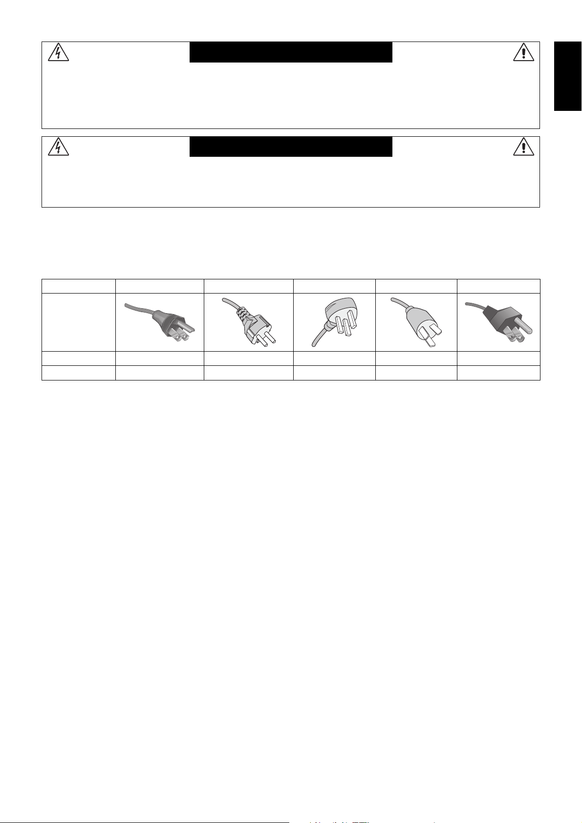
Power Cord Important Information
CAUTION: Please use the power cord provided with this monitor in accordance with the table below. If a power cord is not
supplied with this equipment, please contact your supplier. For all other cases, please use a power cord that matches the
AC voltage of the power outlet and has been approved by and complies with the safety standard of your particular country.
When you use this Monitor in North America, you should use a North America Hospital Grade power cord.
Plug Type North America European Continental U.K. Chinese Japanese
(green dot)
Plug Shape
English
Country
Voltage
NOTE: This product can only be serviced in the country where it was purchased.
U.S.A./Canada EU (except U.K.) U.K. China Japan
120 230 230 220 100
English-1
Page 4

Intended Use
The MDC212C2 Color displays are intended to be used for displaying and viewing of digital images for diagnosis by trained
physicians.
To guarantee the display performance as specifi ed, it must only be used in conjunction with NEC approved display controllers.
MDC212C2 cannot be used for a life-support system.
This device must not be used in digital mammography.
This device is designed for exclusive interconnection with IEC 60601-1 certifi ed equipment.
Contraindications: None known.
Safety Precaution
The unit is designed for exclusive interconnection with IEC 60950-1 certifi ed equipment outside of patient environment and
IEC 60601-1 certifi ed equipment inside the patient environment.
• Equipment connected to digital interfaces must comply with the respective IEC standards (e.g. IEC 60950-1 for data
processing equipment and IEC 60601-1 for medical equipment).
• This device complies with IEC 60601-1-2. To minimize the interference from other equipment, a minimum 0.5 m distance
shall be kept from other potential electromagnetic sources, such as a cell phone.
• To reduce the risk of electric shock, make sure the power cord is unplugged from the wall socket. To fully disengage
the power to the unit, please disconnect the power cord from the ac outlet. Do not remove the front or back cover. No
user serviceable parts inside. Refer servicing to qualifi ed service personnel. The AC outlet shall be readily available and
accessible.
This device is equipped with an integrated front sensor and ambient light sensor complying with the IEC 62563-1 standard
requirements for measurement devices with a calibration traceable to a primary standards laboratory. Therefore, these sensors
can be re-calibrated using external luminance and illuminance meters as a reference, which were calibrated following country
specifi c legal obligations for metrological control. When re-calibrated in a regular manner, the integrated front sensor and
ambient light sensor may then be used for remote quality assurance following the IEC 62563-1 standard. NEC Display Solutions
recommends to check the integrated front sensor and ambient light sensor at intervals of two (2) years.
North America Customers
Grounding reliability can only be achieved when the equipment is connected to an equivalent receptacle marked “Hospital Only”
or “Hospital Grade”. That signal input port need to be connected properly and that any unused signal input port shall not be
accessible for the patient to contact in the patient area after the LCD is integrated into a medical system.
Federal law restricts this device to sale by or on the order of a licensed healthcare practitioner.
European Customers
Unpacking, installation and calibration of this monitor must only be done by authorized and trained personnel. Any installation
done by a non-authorized person is done under his own risk and we accept no responsibility in any device malfunctioning.
Medical Imaging
MDC212C2 is designed for 1600 x 1200 medical imaging.
English-2
Page 5
Registration Information
Declaration of the Manufacturer
Declaration
Declaration of the Manufacturer
Means of Conformity
Device Classifi cation: Class I, non-measuring function
Applicable Rules: Annex IX, Rules 1.4 (Section 1)
and 1.1 (Section 3)
Product Name: MDC212C2
21.3" Diagnostic Imaging Color
LCD monitor
Model Number: MDC212C2
UMDNS Code: 16603
NEC Display Solutions Europe GmbH declares that the product
listed is in conformity with the essential requirements and
provisions of the Council Directive 93/42/EEC, including the
amendments of the Council Directive 2007/47/EC as well as
the Council Directive 2011/65/EU (ROHS), and conforms to the
applicable clauses of the following standards:
– EN 60601-1
– EN 60601-1-2
– EN 61000-3-2
– EN 61000-3-3
– EN 50581:2012
NEC Display Solutions Europe GmbH
Landshuter Allee 12-14. 80637 Muenchen, Germany
FCC Information
1. Use the attached specifi ed cables with this monitor so as not to interfere with radio and television reception.
(1) Please use the supplied power cord or equivalent to ensure FCC compliance.
(2) Please use the supplied shielded video signal cable.
Use of other cables and adapters may cause interference with radio and television reception.
2. This equipment has been tested and found to comply with the limits for a Class B digital device, pursuant to part 15 of the FCC Rules.
These limits are designed to provide reasonable protection against harmful interference in a residential installation. This equipment
generates, uses, and can radiate radio frequency energy, and, if not installed and used in accordance with the instructions, may cause
harmful interference to radio communications. However, there is no guarantee that interference will not occur in a particular installation.
If this equipment does cause harmful interference to radio or television reception, which can be determined by turning the equipment off and
on, the user is encouraged to try to correct the interference by one or more of the following measures:
• Reorient or relocate the receiving antenna.
• Increase the separation between the equipment and receiver.
• Connect the equipment into an outlet on a circuit different from that to which the receiver is connected.
• Consult your dealer or an experienced radio/TV technician for help.
If necessary, the user should contact the dealer or an experienced radio/television technician for additional suggestions.
The user may fi nd the following booklet, prepared by the Federal Communications Commission, helpful: “How to Identify and Resolve
Radio-TV Interference Problems.” This booklet is available from the U.S. Government Printing Offi ce, Washington, D.C., 20402,
Stock No. 004-000-00345-4.
English
Declaration of Conformity
This device complies with Part 15 of FCC Rules. Operation is subject to the following two conditions. (1) This device may not cause harmful
interference, and (2) this device must accept any interference received, including interference that may cause undesired operation.
U.S. Responsible Party: NEC Display Solutions of America, Inc.
Address: 500 Park Boulevard, Suite 1100
Itasca, Illinois 60143
Tel. No.: (630) 467-3000
Type of Product: Display Monitor
Equipment Classifi cation: Class B Peripheral
Model: MDC212C2
We hereby declare that the equipment specifi ed above conforms
to the technical standards as specifi ed in the FCC Rules.
Classifi cation
According to the type of protection against electric shock: CLASS I
According to the degree of protection against electric shock: No applied part
According to the degree of protection against ingress of water as detailed in the current edition of IEC529: IPX0
According to the method of sterilization or disinfection recommended by the manufacturer: Not Specifi ed
According to the degree of safety of application in the presence of a FLAMMABLE AN AESTHETIC MIXTURE WITH AIR or a WITH OXYGEN
OR NITROUS OXIDE: Not AP or APG category
According to the mode of operation: Continuous operation
English-3
Page 6
Recommended use
Safety Precautions and Maintenance
FOR OPTIMUM PERFORMANCE, PLEASE
NOTE THE FOLLOWING WHEN SETTING UP
AND USING THE LCD MONITOR:
WARNING: Do not modify this equipment without authorization of the manufacturer.
WARNING: To disconnect this product from the mains supply disconnect the mains plug from the socket outlet.
WARNING: To avoid risk of electric shock, this equipment must only be connected to a supply mains with protective earth.
WARNING: No modifi cation of this equipment is allowed.
WARNING: For EMC details information, please contact the NEC local representative.
• DO NOT OPEN THE MONITOR. There are no user serviceable parts inside and opening or removing covers may expose
you to dangerous shock hazards or other risks. Refer all servicing to qualifi ed service personnel.
• Do not spill any liquids into the cabinet or use your monitor near water.
• Do not insert objects of any kind into the cabinet slots, as they may touch dangerous voltage points, which can be harmful or
fatal or may cause electric shock, fi re or equipment failure.
• Do not place any heavy objects on the power cord. Damage to the cord may cause shock or fi re.
• Do not place this product on a sloping or unstable cart, stand or table, as the monitor may fall, causing serious damage to
the monitor.
• The power supply cord you use must have been approved by and comply with the safety standards of your country.
(Type H05VV-F 3G 1mm
• In UK, use a BS-approved power cord with molded plug having a black (5A) fuse installed for use with this monitor.
• Do not place any objects onto the monitor and do not use the monitor outdoors.
• Do not bend power cord.
• Do not use monitor in high temperatured, humid, dusty, or oily areas.
• For reliable performance and long useful life of this product, it is mandatory to not cover any vents on the monitor.
• Vibration can damage the backlight. Do not install where the monitor will be exposed to continual vibration.
• If monitor or glass is broken, do not come in contact with the liquid crystal and handle with care.
• To prevent damage to the LCD monitor caused by tipping over due to earthquakes or other shocks, make sure to install the
monitor in a stable location and take measures to prevent falling.
• Please do not touch patient and this medical device at the same time.
Immediately turn off the power, unplug your monitor from the wall outlet and move to a safe location then refer servicing to qualifi ed
service personnel under the following conditions. If the monitor is used in this condition, the monitor may cause fall, fi re and electric
shock:
• If the monitor stand has been cracked or peeled.
• If the monitor has been wobbled.
• If the monitor has an unusual odor.
• When the power supply cord or plug is damaged.
• If liquid has been spilled, or objects have fallen into the monitor.
• If the monitor has been exposed to rain or water.
• If the monitor has been dropped or the cabinet damaged.
• If the monitor does not operate normally by following operating instructions.
• Allow adequate ventilation around the monitor so that heat can properly dissipate. Do not block ventilated
CAUTION
• The power cable connector is the primary means of detaching the system from the power supply.
• Handle with care when transporting. Save packaging for transporting.
• Do not touch LCD panel surface while transporting, mounting and setting.
• Carry the monitor holding the built-in handle and bottom frames of the monitor.
• Do not carry holding only the stand.
• This monitor has the integrated front sensor. Do not touch the integrated front sensor while carrying the
2
should be used in Europe).
openings or place the monitor near a radiator or other heat sources. Do not put anything on top of monitor.
The monitor should be installed close to a power outlet which is easily accessible.
Applying pressure on the LCD panel can cause permanent damage.
monitor. Do not apply any stress to the integrated front sensor.
English-4
Page 7
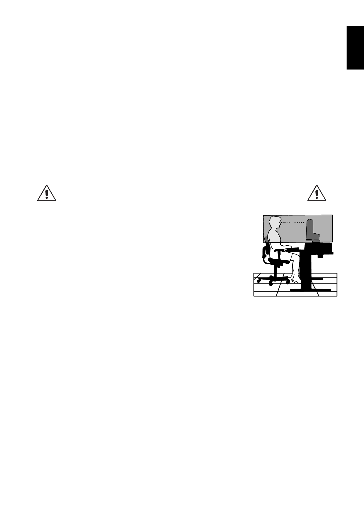
Image Persistence: When a residual or “ghost” image of a previous image remains visible on the screen, this is called image
persistence. Unlike CRT monitors, LCD monitors’ image persistence is not permanent, but constant images being displayed for
a long period of time should be avoided.
To alleviate image persistence, turn off the monitor for as long as the previous image was displayed. For example, if an image
was on the monitor for one hour and a residual image remains, the monitor should be turned off for one hour to erase the image.
NOTE: The power management function of the operating system must be activated so that the monitor’s backlight is
automatically switched off after maximum 15 minutes whenever the system is not in use.
Maintenance:
a) Before fi rst use of this monitor for diagnostic imaging, an initial calibration to DICOM Part 14 is highly recommended.
To ensure constant visual quality over the life of this monitor, the recommended time interval to re-calibrate this model is
12 months.
b) This model is equipped with an integrated front sensor and ambient light sensor complying with the IEC 62563-1 standard
requirements for measurement devices with a calibration traceable to a primary standards laboratory. Therefore, these sensors
can be re-calibrated using external luminance and illuminance meters as a reference, which were calibrated following country
specifi c legal obligations for metrological control. When re-calibrated in a regular manner, the integrated front sensor and
ambient light sensor may then be used for remote quality assurance following the IEC 62563-1 standard. NEC Display Solutions
recommends to re-calibrate the integrated front sensor and ambient light sensor latest after 2 years.
NOTE: A regular “Reference Calibration” with the NEC Display Solutions GammaCompMD QA software and a properly-
managed USB color sensor is highly recommended in order to keep front sensor measurements accurate over time.
The recommended time interval to re-adjust the front sensor is 24 months.
CORRECT PLACEMENT AND ADJUSTMENT OF THE MONITOR CAN
REDUCE EYE, SHOULDER AND NECK FATIGUE. CHECK THE
FOLLOWING WHEN YOU POSITION THE MONITOR:
English
• For optimum performance during normal operation, allow 30 minutes for the display
to warm up. For re-calibration and DICOM conformance tests, please allow at least
60 minutes to achieve best results.
• Adjust the monitor height so that the top of the screen is at or slightly below eye level.
Your eyes should look slightly downward when viewing the middle of the screen.
• Position your monitor no closer than 40 cm (15.75 inches) and no further away than
70 cm (27.56 inches) from your eyes. The optimal distance is 50 cm (19.69 inches).
• Rest your eyes periodically by focusing on an object at least 20 feet away. Blink often.
• Position the monitor at a 90° angle to windows and other light sources to minimize glare
and refl ections. Adjust the monitor tilt so that ceiling lights do not refl ect on your screen.
• Avoid displaying fi xed patterns on the monitor for long periods of time to avoid image
persistence (after-image effects).
• Get regular eye checkups.
Cleaning the LCD Panel
• When the LCD is dusty, please gently wipe with a soft cloth.
• Please do not rub the LCD panel with hard or coarse material.
• Please do not apply pressure to the LCD surface.
• Please do not use OA cleaner as it will cause deterioration or discoloration on the LCD surface.
Cleaning the Cabinet
• Unplug the power supply
• Gently wipe the cabinet with a soft cloth
• To clean the cabinet, dampen the cloth with a neutral detergent and water, wipe the cabinet and follow with a dry cloth.
NOTE: Many plastics are used on the surface of the cabinet. DO NOT clean with benzene, thinner, alkaline detergent,
alcoholic system detergent, glass cleaner, wax, polish cleaner, soap powder, or insecticide. Do not touch rubber or
vinyl to the cabinet for a long time. These types of fl uids and fabrics can cause the paint to deteriorate, crack or peel.
English-5
Page 8
Contents
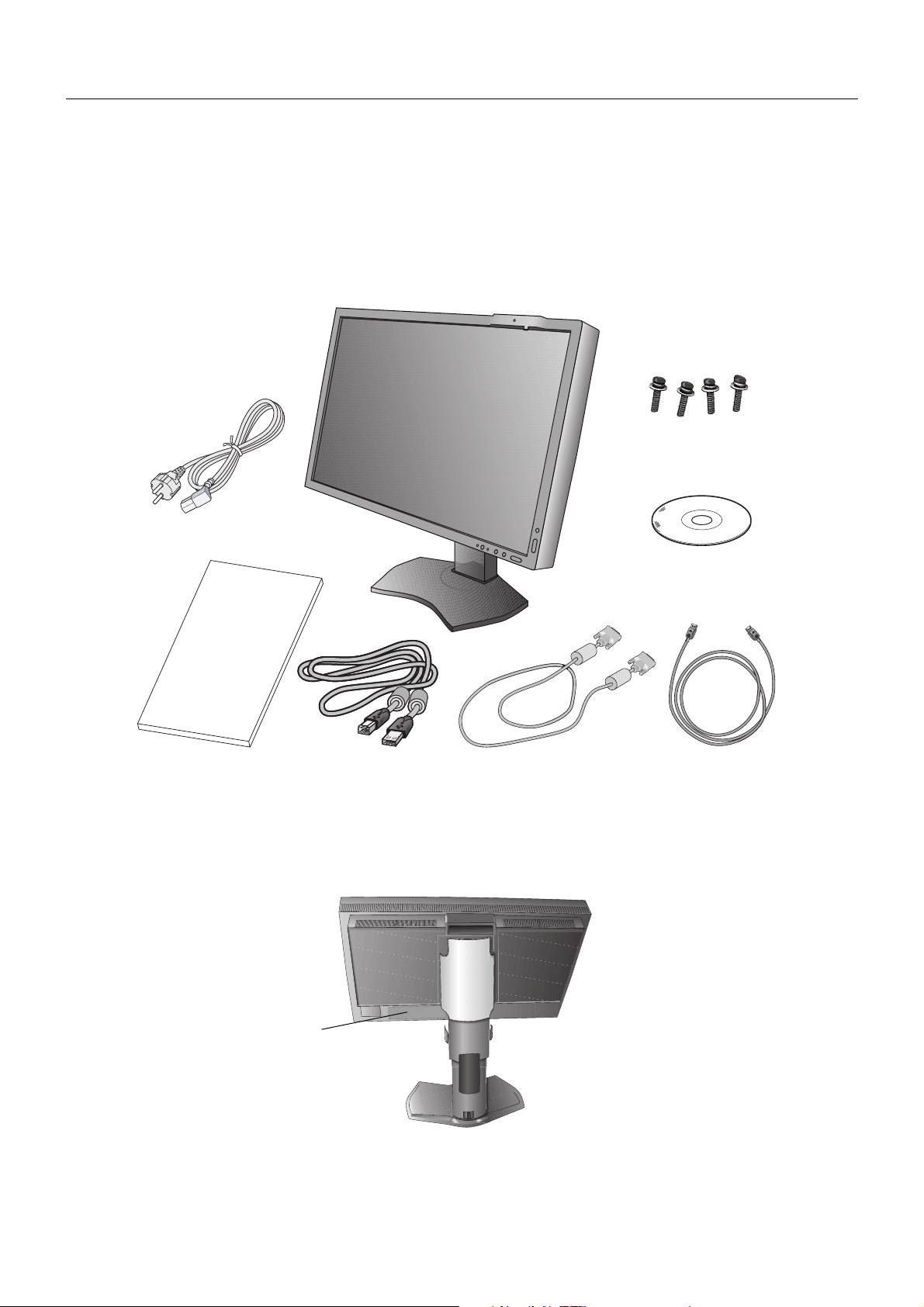
Your new NEC monitor box* should contain the following:
• Monitor with tilt/swivel/pivot/height adjust stand
• Power Cord*
• DVI-D cable
• DisplayPort cable
• USB Cable
• Quick Reference Guide
• CD-ROM
• Screw (x 4) (to mount the monitor to a fl exible arm (page 11))
1
Screws
Power Cord*
Quick Reference
Quick Reference Guide DVI-D cable DisplayPort cable
* Remember to save your original box and packing material to transport or ship the monitor.
*1 Type and number of power cords included will depend on the where the LCD monitor is to be shipped. When more than one power cord is
included, please use a power cord that matches the AC voltage of the power outlet and has been approved by and complies with the safety
standard of your particular country.
1
CD-ROM
Guide
USB Cable
The model name is on the label.
Rating label on the
back of the display.
English-6
Page 9
Quick Start
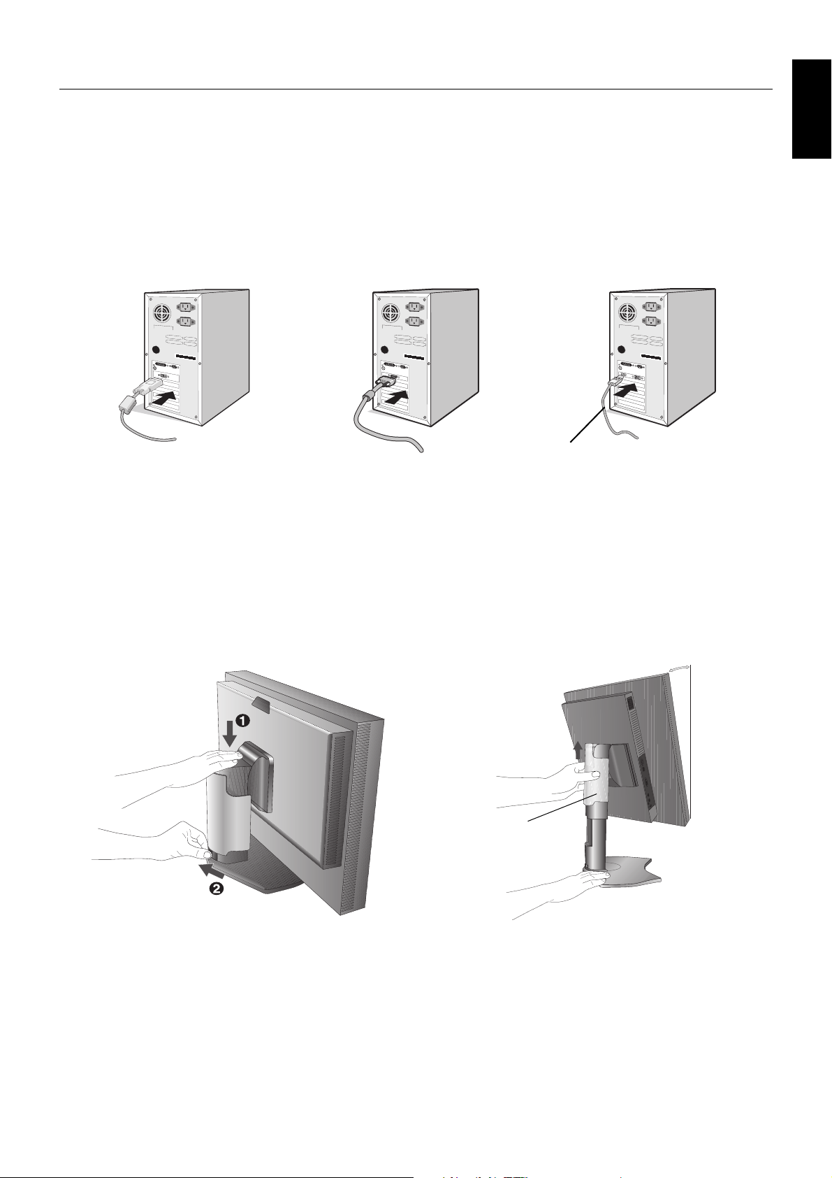
To connect the LCD monitor to your system, please follow these instructions:
NOTE: Make sure to read “Recommended Use” (page 4) before installation.
In order to display the maximum resolution, a display controller that can output a resolution of 1600 x 1200 is needed.
1. Turn off the power to your computer.
2. For a PC with DVI digital output: Connect the DVI signal cable to the connector of the display card in your system
(Figure A.1). Tighten all screws.
For a PC with Analog output: Connect a 15-pin mini D-SUB signal cable (not included) to the connector of the display card
in your system (Figure A.2).
For a PC with DisplayPort output: Connect the DisplayPort cable to the connector of the display card in your system
(Figure A.3).
DisplayPort cable
Figure A.1 Figure A.2
Figure A.3
English
NOTE: 1. Please use a DisplayPort cable with a DisplayPort logo.
2. When removing the DisplayPort cable, hold down the top button to release the lock.
3. Height adjustment is locked by lock button. Place hand on top of the monitor to push down the screen to the lowest position.
Slide the lock button to unlock (Figure B.1).
NOTE: Handle with care when unlocking stand.
Place hands on each side of the monitor to tilt the LCD panel 30-degree angle and lift up to the highest position.
Slide the cable cover up (Figure B.2).
NOTE: Cable cover is not removable.
30° Tilt
Cable cover
Figure B.1 Figure B.2
English-7
Page 10
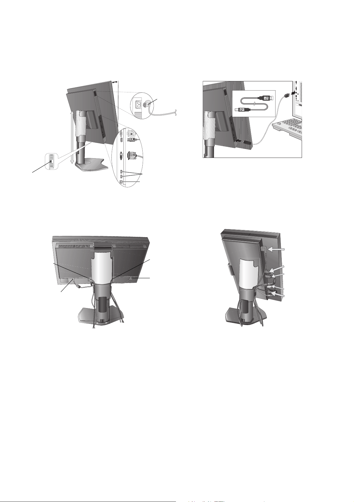
4. Connect all cables to the appropriate connectors (Figure C.1). When using the USB cable, connect the B type connector
B Type
to the USB upstream port on the right back side of the monitor and the A type connector to the downstream port on the
computer (Figure C.1a). If using the cord from a USB device, plug into one of the downstream ports of the monitor.
NOTE: Incorrect cable connections may result in irregular operation, damage display quality/components of LCD module
and/or shorten the module’s life.
For re-calibration and display management, the USB cable shipped with the display must be connected with a USB
port of the computer as well.
30° Tilt
A Type
A Type
Power cord
Highest
B Type
Stand
Position
D-SUB
DisplayPort
B Type
DVI-D
Figure C.1a
USB downstream
USB downstream
USB upstream
Figure C.1
5. To keep the cables neatly organized, place them into the cable management system that is built into the stand.
Place the cables in the hooks fi rmly and evenly (Figure C.2 and Figure C.3).
6. Please check that you can still rotate, raise and lower the monitor screen when you have installed the cables.
Power Cord
DVI Cable
D-SUB Cable*
Power Cord
1
D-SUB Cable*
DisplayPort Cable
1
USB Cable
1
: Cable not included.
*
DVI Cable
USB Cable
Figure C.2 Figure C.3
English-8
Page 11
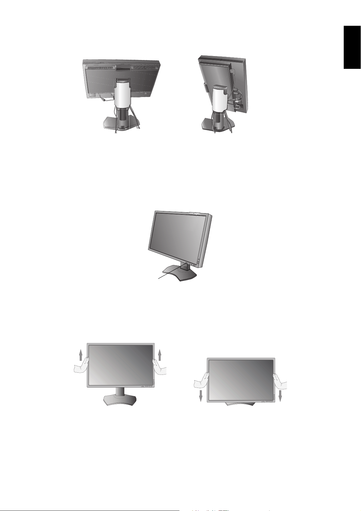
7. Slide down the cable cover (Figure D.1).
8. Connect one end of the power cord to the AC inlet on the back of the monitor and the other end to the power outlet.
NOTE: Please refer to Caution section of this manual for proper selection of AC power cord.
Figure D.1
9. Turn on the monitor with the front power button (Figure E.1) and the computer.
10. No Touch Auto Adjust automatically adjusts the monitor to optimal settings upon initial setup for most timings. For further
adjustments, use the following OSD controls:
• AUTO CONTRAST (Analog input only)
• AUTO ADJUST (Analog input only)
Refer to the Controls section of this User’s Manual for a full description of these OSD controls.
NOTE: If you have any problems, please refer to the Troubleshooting section of this User’s Manual.
English
Power Button
Figure E.1
Raise and Lower the Monitor Screen
The monitor may be raised or lowered in either Portrait or Landscape mode.
To raise or lower screen, place hands on each side of the monitor and lift or lower to the desired height (Figure RL.1).
NOTE: Handle with care when raising or lowering the monitor screen.
Figure RL.1
English-9
Page 12
Screen Rotation
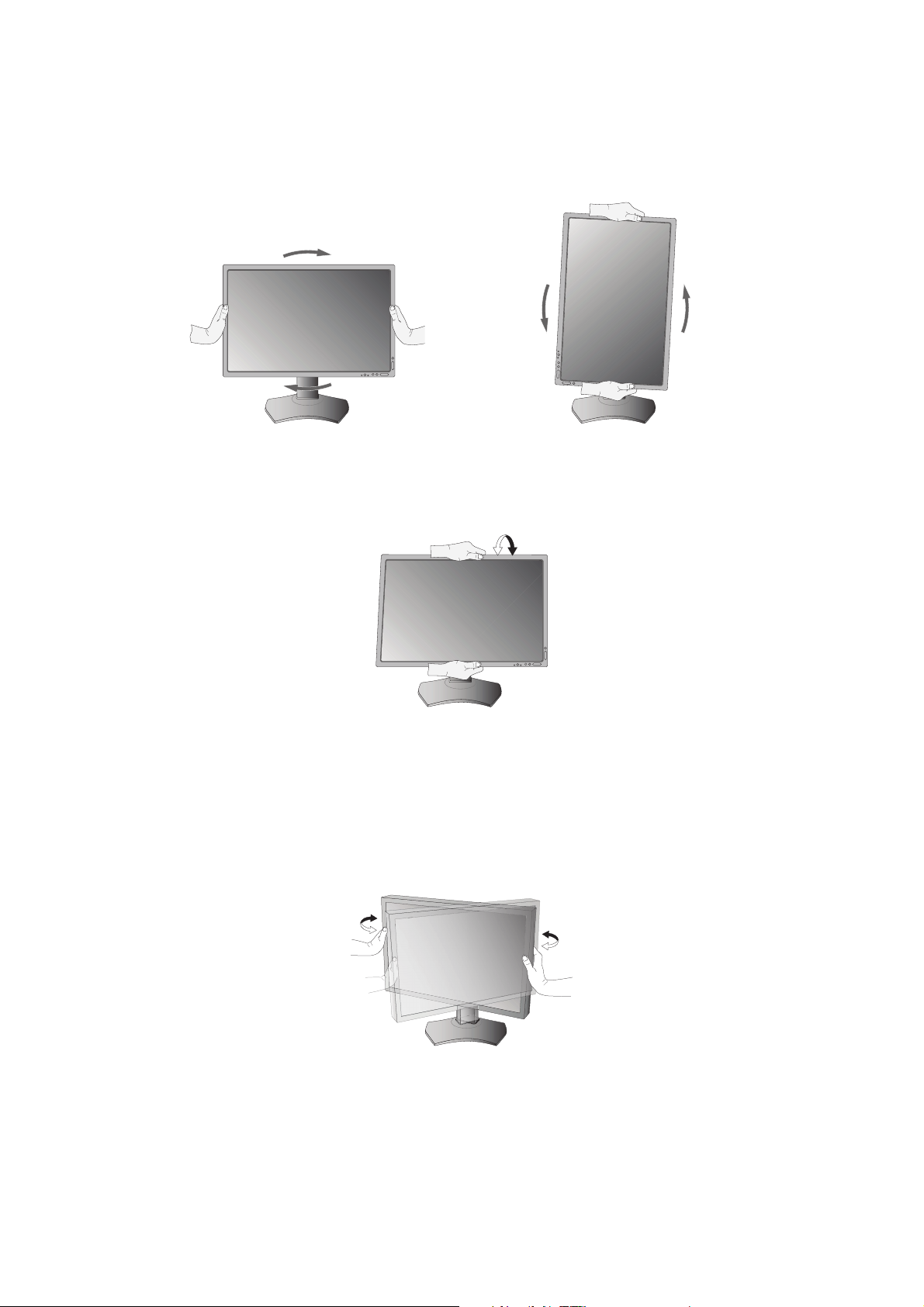
Before rotating, the screen must be raised to the highest level and tilt to avoid knocking the screen on the desk or pinching your
fi ngers. Disconnect all cables.
To raise the screen, place hands on each side of the monitor and lift up to the highest position (Figure RL.1).
To rotate screen, place hands on each side of the monitor screen and turn clockwise from Landscape to Portrait or counterclockwise from Portrait to Landscape (Figure R.1).
To rotate OSD menu between landscape and portrait, refer to “Controls” section.
Figure R.1
Tilt
Grasp top and bottom sides of the monitor screen with your hands and adjust the tilt as desired (Figure TS.1).
Figure TS.1
NOTE: Handle with care when tilting the monitor screen.
NOTE: This monitor has the integrated front sensor. Do not touch the integrated front sensor while carrying the monitor.
Do not apply any stress to the integrated front sensor.
Swivel
Grasp both sides of the monitor screen with your hands and adjust the swivel as desired (Figure TS.2).
Figure TS.2
English-10
Page 13
Flexible Arm Installation
This LCD monitor is designed for use with a fl exible arm.
To prepare the monitor for alternate mounting purposes:
• Follow the instructions provided by the manufacturer of the display mount.
• To meet the safety requirements, the monitor must be mounted to an arm that supports the weight of the monitor.
See page 25 for details. Remove the monitor stand before mounting.
* Contact your dealer for more information.
Remove Monitor Stand for Mounting
To prepare the monitor for alternate mounting purposes:
1. Disconnect all cables.
2. Place hands on each side of the monitor and lift up to the highest position.
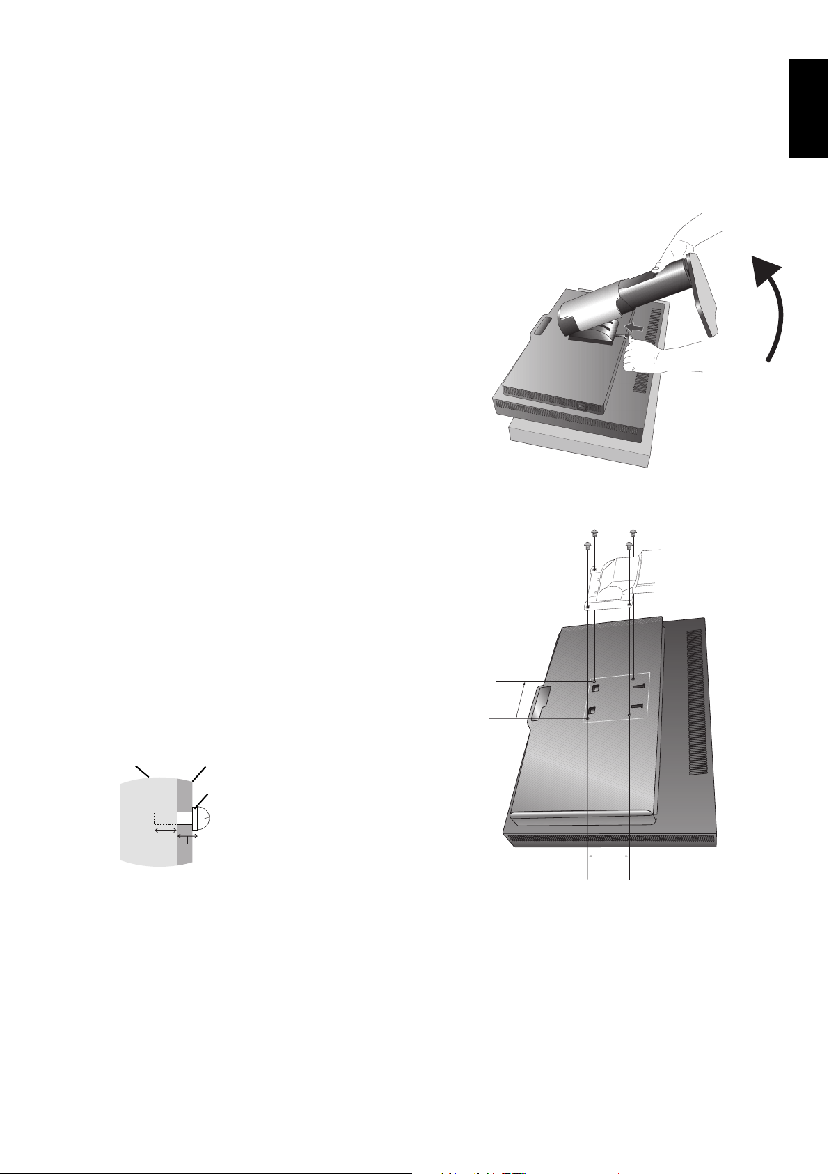
3. Place monitor face down on a non-abrasive surface (Figure S.1).
Be sure to not apply any stress or pressure to the integrated front sensor.
To avoid this, lay the monitor face down on a desk or table with the integrated
front sensor, situated off the edge (Figure S.1).
4. Place one hand around the base and one hand on the Quick Release Lever.
Push and hold the Quick Release Lever in the direction indicated by the
arrows (Figure S.1).
5. Lift up the stand to unhook it from the monitor (Figure S.1).
The monitor can now be mounted using an alternate method.
Reverse the process to reattach stand.
NOTE: Handle with care when removing monitor stand.
Figure S.1
English
Mount the Flexible arm
This LCD monitor is designed for use with a fl exible arm.
1. Follow the instructions on how Remove Monitor Stand for
Mounting to remove the stand.
2. Using the attached 4 screws, attach the arm to the monitor
(Figure F.1).
Caution: Use ONLY the screws (4 pcs) that are included, M4 size
screws (Length: thickness of bracket and washer +
5-7 mm) when mounting to avoid damage to the monitor
and stand. To fulfi l the safety requirements the monitor
must be mounted to an arm which guaranties the
necessary stability under consideration of the weight of
the monitor. The LCD monitor should only be used with
an approved arm (e.g. TUEV GS mark).
Unit
5-7 mm
NOTE: Tighten all screws.
(recommended Fasten Force: 98 - 137N•cm)
Mounting
Bracket
Washer
Screw
Thickness
of bracket
and washer
100 mm
100 mm
Weight of LCD assembly: 4.8 kg
Figure F.1
English-11
Page 14
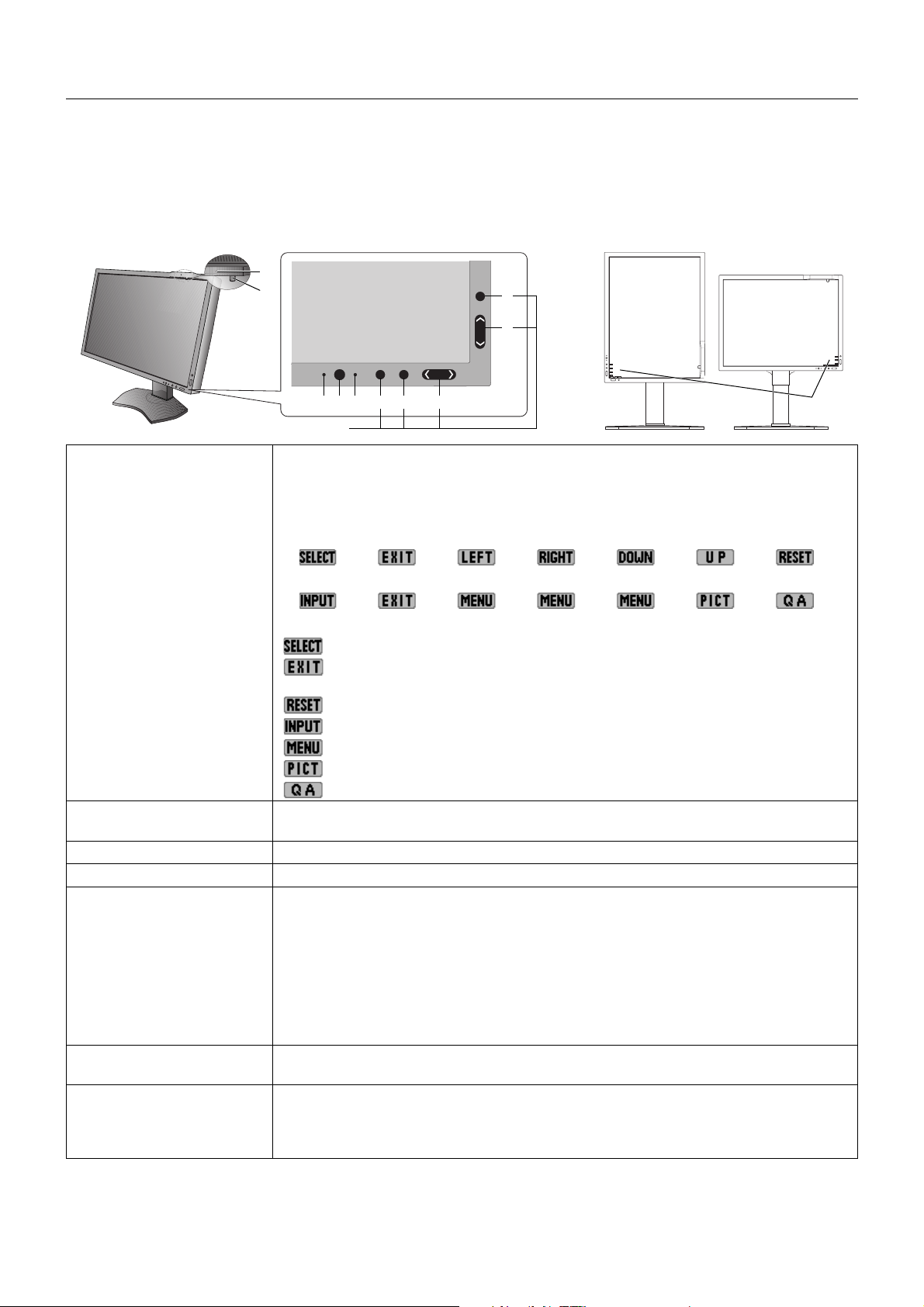
Controls
OSD (On-Screen Display) control buttons on the front of the monitor
function as follows:
To access the OSD menu, press the MENU button.
The Key Guide appears pressing any button when not in the OSD control menu.
NOTE: The OSD must be closed in order to change the signal input.
6
7
E
D
34
2
5. Control Buttons
1 KEY GUIDE The Key Guide appears on the screen when the OSD control menu is accessed.
The Key Guide will rotate when the OSD control menu is rotated.
Perform along the notifi cation of each key.
NOTE: The KEY GUIDE appears as follows:
• KEY GUIDE when OSD menu is displayed.
• KEY GUIDE when OSD menu is undisplayed.
Each KEY GUIDE works as follows:
- Selects the item.
- Exits any OSD sub menu.
Exits the OSD Control menu.
- Resets the OSD back to factory settings.
- Changes the input source.
- Shows OSD menu.
- Shows PICTURE MODE.
- Shows the quick screen QA test pattern.
2 AMBIENT LIGHT SENSOR Detects the level of ambient light, allowing the monitor to make adjustments to various
settings. Do not cover this sensor (See page 20).
3 POWER Turns the monitor on and off.
4 LED Indicates that power is on.
5 Control Buttons A. INPUT button, SELECT button
B. EXIT button
C. LEFT/RIGHT button, MENU button
D. UP/DOWN button, MENU/PICT button
E. RESET button, QA button
NOTE: When not in the OSD control menu, press the RESET button for at least
3 seconds to display the quick screen QA test pattern (grayscale) drawing and check the
display performance.
6 HUMAN SENSOR Detects human presence in front of the monitor by infrared radiation emitted from human
body. Do not cover this sensor (See page 22).
7 FRONT SENSOR Detects screen luminance and color changes over time.
Used for luminance and color stabilization, standalone (Self Calibration, Gamma Adjust,
Gamma Measure) and network (Gamma Adjust, Gamma Measure) controlled calibrations
and conformance tests.
CBA
1
English-12
Page 15
SETTING OSD LANGUAGE
• Use the control buttons (LEFT/RIGHT or UP/DOWN or MENU) to access the “LANGUAGE SELECTION” menu.
• Press the LEFT/RIGHT or UP/DOWN buttons to select the desired OSD language.
• To exit from this OSD menu, press EXIT button.
NOTE: Setting the OSD language is only necessary upon initial setup. The OSD language will stay the same until changed
by the user.
Luminance/Contrast Controls
LUMINANCE
Adjusts the overall image and background screen luminance.
NOTE: For low luminance settings, the display will automatically compensate by adjusting the screen contrast.
This will result in a reduced contrast ratio.
For high luminance settings, the display will automatically compensate by turning down uniformity
compensation. This may result in decreased uniformity.
If digital compensation occurs, the luminance value on the OSD will change to magenta.
NOTE: The optimal display performance will be in the range where the OSD luminance value is black. When the
display cannot achieve the desired luminance, the numerical luminance value on the OSD will blink.
BLACK
Adjusts the black luminance.
When low settings are selected that cannot be displayed, the indicator on the OSD will turn magenta.
CONTRAST (Analog input only)
Adjusts the overall image and background screen brightness by input signal level.
NOTE: It is recommended to use LUMINANCE to adjust screen brightness for lower power consumption and
improved image quality.
English
AUTO CONTRAST (Analog input only)
Adjusts the image displayed for non-standard video inputs.
Image Controls
LEFT / RIGHT
Controls Horizontal Image Position within the display area of the LCD.
DOWN / UP
Controls Vertical Image Position within the display area of the LCD.
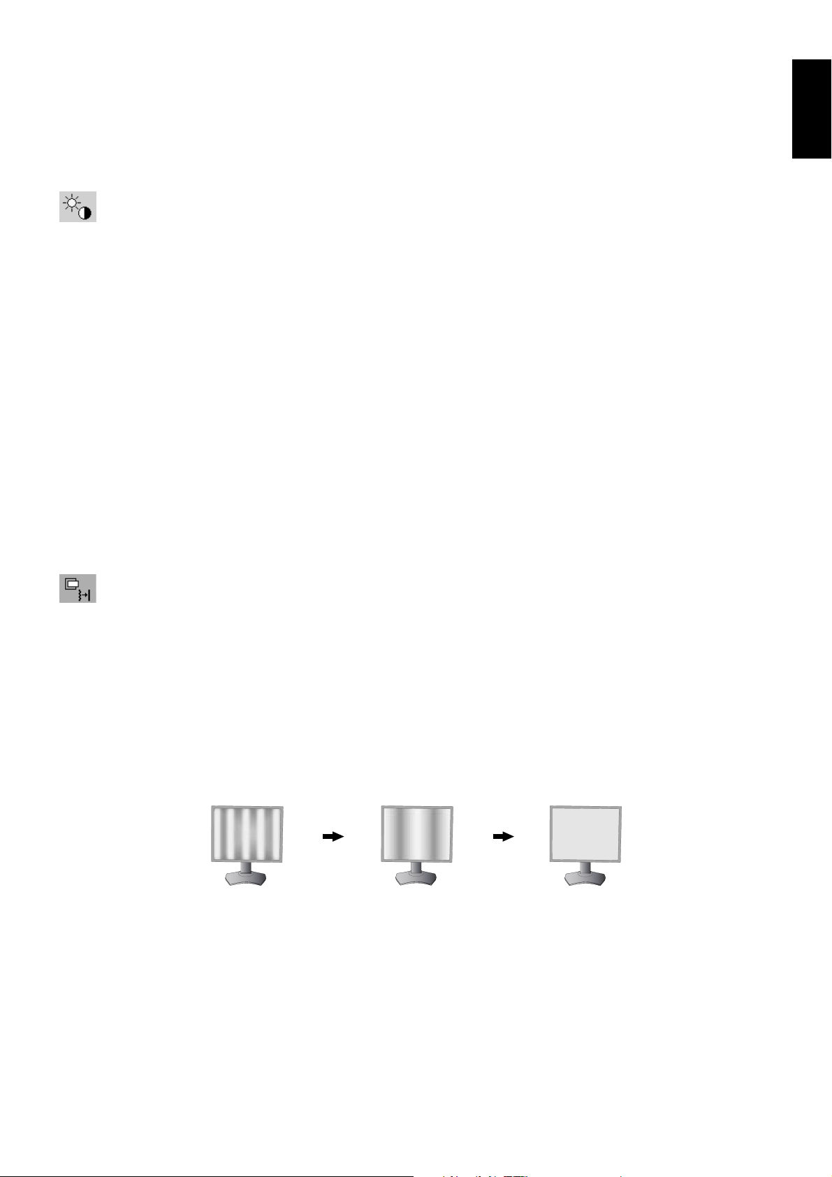
H.SIZE (V.SIZE) (Analog input only)
Adjusts the horizontal size by increasing or decreasing this setting.
If the “AUTO ADJUST” function do not give you a satisfactory picture setting, a further tuning can be performed using
the “H.SIZE (or V.SIZE)” function (dot clock). For this a Moiré test pattern could be used. This function may alter the
width of the picture. Use LEFT/RIGHT Menu to center the image on the screen. If the H.SIZE (or V.SIZE) is wrongly
calibrated, the result would look like the left drawing. The image should be homogeneous.
When H.SIZE value is
wrong.
When H.SIZE value is
improved.
When H.SIZE value is
correct.
English-13
Page 16
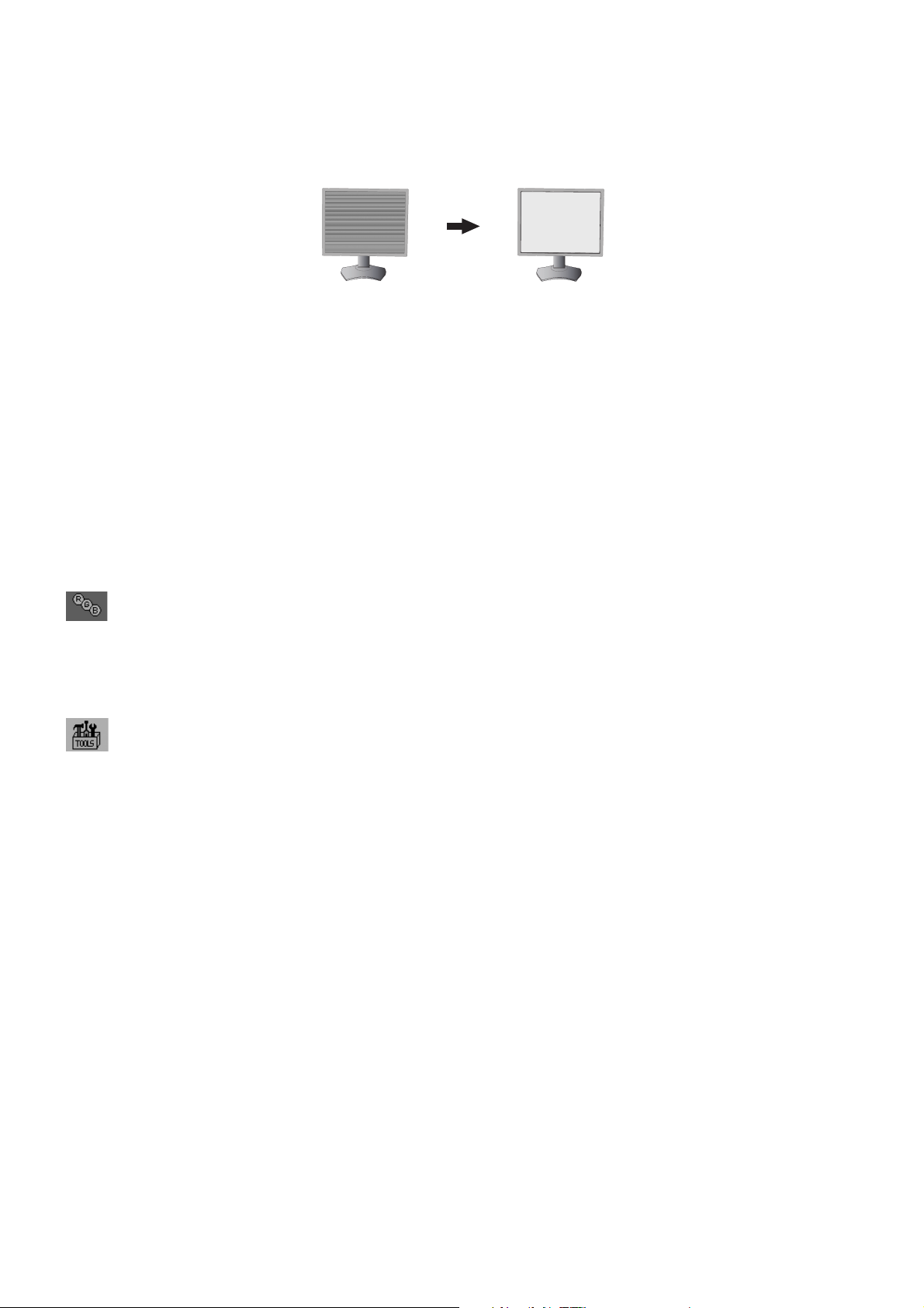
FINE (Analog input only)
Improves focus, clarity and image stability by increasing or decreasing this setting.
If the “AUTO ADJUST” function and the “H.SIZE” function do not give you a satisfactory picture setting, a fi ne tuning
can be performed using the “FINE” function.
For this a Moiré test pattern could be used. If the FINE value is wrongly calibrated, the result would look like the left
drawing. The image should be homogeneous.
When FINE value is
wrong.
When FINE value is
correct.
EXPANSION
Sets the zoom method.
FULL: The image is expanded to full screen, regardless of the resolution.
ASPECT: The image is expanded without changing the aspect ratio.
OFF: The image is not expanded.
SHARPNESS
This function is digitally capable of keeping crisp image at any time. It is continuously adjustable to get as distinct or as
soft an image as your prefer and set independently by different timings.
AUTO ADJUST (Analog input only)
Automatically adjusts the Image Position and H. SIZE settings and FINE settings.
When using AUTO ADJUST, we recommend to display a white image to fi ll the screen.
Color Control Systems
PICTURE MODE
Changes the Picture mode that is most suitable for the type of content that is shown. 5 Picture modes are available
to be customized. See Advanced menu Tag1 PICTURE MODE (page 19) and “Using the PICTURE MODE function”
(page 17) for more information.
Tools
VIDEO DETECT
Selects the method of video detection when more than one video input is connected.
FIRST: When current video input signal is not present, then the monitor searches for a video signal from the other
video input(s) port. If a video signal is present in another port, then the monitor switches the video source input port
to the new found video source automatically. The monitor will not look for other video signals while the current video
source is present.
LAST: When the monitor is displaying a signal from the current source and a new secondary source is supplied to
the monitor, then the monitor will automatically switch to the new video source. When current video input signal is not
present, then the monitor searches for a video signal from the other video input port(s). If the video signal is present in
another port, then the monitor switches the video source input port to the new found video source automatically.
NONE: The Monitor will not search the other video input port unless the monitor is turned on.
English-14
Page 17

OFF MODE
The Intelligent Power Manager allows the monitor to enter into a power saving mode after a period of inactivity.
The OFF MODE has four settings.
OFF: Monitor does not go into power save mode when the input signal is lost.
STANDARD: Monitor enters power save mode automatically when the input signal is lost.
ADVANCED: The signal detection circuit works always. Recovery time to normal mode is faster than STANDARD.
Power consumption is slightly higher than STANDARD.
NOTE: When set to STANDARD, if the image does not reappear when the signal is restarted, please change the
setting to ADVANCED.
OPTION: Monitor enters power save mode automatically when the amount of surrounding light goes below the level that
is determined by the user. The level can be adjusted in OFF MODE SETTING in Tag 6 of the Advanced OSD menu.
When in power save mode, the LED on the front of the monitor blinks amber. While in power save mode, push any of
the front buttons, except for POWER and SELECT to return to normal.
When the amount of surrounding light returns to normal levels, the monitor will automatically return to normal mode.
MENU Tools
LANGUAGE
OSD control menus are available in nine languages.
OSD LEFT/RIGHT
You can choose where you would like the OSD control image to appear on your screen. Selecting OSD Location
allows you to manually adjust the position of the OSD control menu left or right.
OSD DOWN/UP
You can choose where you would like the OSD control image to appear on your screen. Selecting OSD Location
allows you to manually adjust the position of the OSD control menu Up or Down.
English
OSD TURN OFF
The OSD control menu will stay on as long as it is use. You can select how long the monitor waits after the last touch
of a button to shut off the OSD control menu. The preset choices are 10-120 seconds by 5-second increments.
OSD LOCK OUT
This control completely locks out access to all OSD control functions. When attempting to activate OSD controls while
in the Lock Out mode, a screen will appear indicating the OSD controls are locked out.
There are two types of OSD LOCK OUT:
OSD LOCK OUT with no control: To activate the OSD Lock Out function, press SELECT, then “RIGHT” button and
hold down simultaneously. To deactivate the OSD Lock Out, press SELECT, then “RIGHT” button and hold down
simultaneously while in the OSD menu. No controls can be adjusted while in the lock out mode.
CUSTOM: Refer to the Advanced OSD Menu.
NOTE: OSD control menu will disappear after the time set in OSD TURN OFF or when the EXIT button is pressed.
Input Select and Quick screen QA test function are not locked out.
OSD COLOR
Adjusts the color of the OSD Menu. “Tag window frame color”, “Item select color” and “Adjust window frame color” can
be changed to Red, Green, Blue, or Gray.
FACTORY PRESET
Selecting FACTORY PRESET allows you to reset all OSD control settings back to the factory settings except
VIDEO DETECT, LANGUAGE, OSD LOCK OUT and OSD COLOR. Individual settings can be reset by highlighting the
control to be reset and pressing the RESET button.
English-15
Page 18

QA TEST
Provides a quick daily visual image quality check of this diagnostic monitor by just using a button on the monitor.
GRAYSCALE MODE
This function changes the display image to monochrome.
OFF: The Display Image is COLOR.
MODE1: The signal Input is 8 bit monochrome. The display shows a grayscale image. This mode uses only the Green
channel of an R/G/B input signal.
MODE2: Input is R/G/B Color, but the monitor changes the color space to YUV. The displayed image will become
monochrome. Only Y data passes the R/G/B LUT.
Information
Provides information about the current resolution display and technical data including the preset timing being used and
the horizontal and vertical frequencies. Indicates the model and serial numbers of your monitor.
OSD Warning
OSD Warning menus disappear with EXIT button.
NO SIGNAL: This function gives a warning when there is no Horizontal or Vertical Sync. After power is turned on or
when there is a change of input signal, the No Signal window will appear.
OUT OF RANGE: This function gives a recommendation of the optimized resolution and refresh rate. After the power
is turned on or there is a change of input signal or if the video signal doesn’t have proper timing, the Out Of Range
menu will appear.
BACKLIGHT LIFETIME: At 1000/500/0 hours of estimated remaining backlight lifetime, a warning message will be
displayed. Please contact your supplier when this warning message is displayed.
LUMINANCE WARNING: This warning indicates that the monitor cannot keep user set luminance levels. Please
contact your supplier when this warning message is displayed.
If you need detailed information about the controls, please use the ADVANCED OSD menu.
English-16
Page 19
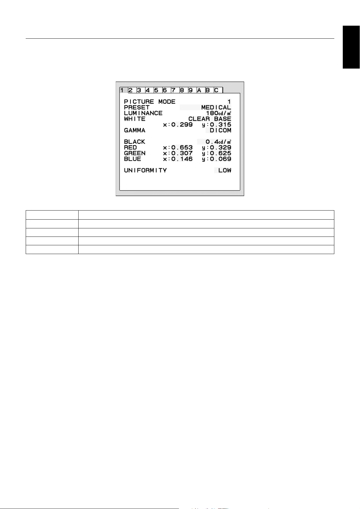
Using the PICTURE MODE function
Choose the Picture mode which is the most suitable for the type of displayed content.
These are the available modes: MEDICAL, Gamma 2.2 and PROGRAMMABLE.
• Each PICTURE MODE includes PRESET, LUMINANCE, WHITE, Color Gamut (RED, GREEN, BLUE), GAMMA, BLACK,
UNIFORMITY, AMBIENT LIGHT COMP., RESPONSE IMPROVE and (6-AXIS ADJUST) settings.
You can change these settings in Tag1 and Tag2 on the Advanced OSD.
The type of PRESET
English
PRESET PURPOSE
MEDICAL
Gamma 2.2
TEXT
PROGRAMMABLE
NOTE: A “PICTURE MODE IS LOCKED” warning message appears when PICTURE MODE is locked out.
To unlock the PICTURE MODE settings, press “SELECT” and “UP” buttons at the same time.
You can unlock the PICTURE MODE settings by OSD LOCK OUT in Tag6 of Advanced OSD as well.
Factory setting. Recommended setting for displaying medical images.
Medical settings for endoscopic imaging view. Setting for Gamma 2.2 image.
The conditions are optimal for viewing documents and sRGB images.
For Hardware Calibration settings by NEC Display Solutions QA software (some OSD settings are disabled).
English-17
Page 20
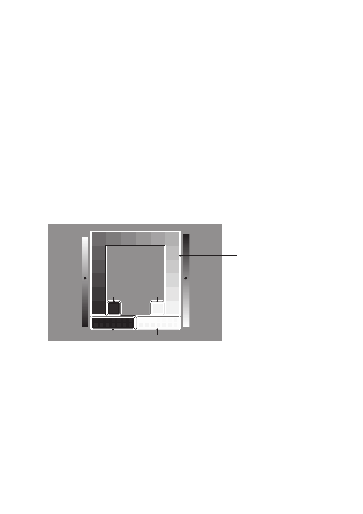
Quick screen QA test function
Allows the monitor to display an internal test pattern similar to AAPM TG18-QC, without using an external signal source. A quick
overall visual evaluation as well as an inspection of the gray levels according to DICOM is available with this built-in method.
- If the monitor is connected with a video signal source (computer):
Make sure that no OSD menu is displayed, then press the RESET button for more than 3 seconds or press the RESET button
twice. This will start drawing the test pattern across the screen, then start the DICOM MEASURE routine, if GAMMA in the
PICTURE MODE is set to DICOM. Please note that the monitor must be warmed up for at least 30 minutes for this test to
deliver valid results. The test pattern will hide the image of the signal source.
After fi nishing the measurements done with the integrated front sensor, the result will be displayed.
The MAX. GSDF ERROR result (in %) is a quick indicator of the gray level quality against the ideal DICOM curve. Depending on
the QA standard which is used in your country, different GSDF error limits may exist. Please compare the actual result with your
local regulations or guidelines.
You may now check the gray levels and the overall quality visually.
To exit the QA TEST mode, press “EXIT”. The image of the video signal source will return.
- If the monitor is not connected with any video signal source:
Make sure that only the NO SIGNAL message is displayed, then press the RESET button for more than 3 seconds. This will
start drawing the test pattern across the screen, then start the DICOM MEASURE routine, if GAMMA in the PICTURE MODE is
set to DICOM. Please note that the monitor must be warmed up for at least 30 minutes for this test to deliver valid results.
After fi nishing the measurements done with the integrated front sensor, the result will be displayed.
The MAX. GSDF ERROR result (in %) is a quick indicator of the gray level quality against the ideal DICOM curve. Depending on
the QA standard which is used in your country, different GSDF error limits may exist. Please compare the actual result with your
local regulations or guidelines.
You may now check the gray levels visually to compare with the measurement result.
To exit the QA TEST mode, press “EXIT”.
16 level luminance patches should
be discernible from each other.
Luminance ramp elements should
be visible without any bending.
5% and 95% luminance patches
should be discernible from the
surrounding 0% luminance
respectively 100% luminance
patches.
Low-contrast patterns create
with 8 bit digital driving patterns.
English-18
Page 21
Advanced OSD
<How to use the advanced OSD>
• When both OSD and Key Guide are off, push the “RESET” and “EXIT” buttons two times simultaneously.
• You will see the Advanced OSD.
This menu is larger than the normal OSD.
<How to exit the advanced OSD>
• Push the “EXIT” button.
To make an adjustment, ensure that the tag is highlighted, then press “SELECT”.
To move to another tag, press “EXIT”, then press “LEFT” or “RIGHT” to highlight another tag.
Tag1 PICTURE MODE Selects the PICTURE MODE.
PRESET Sets PICTURE MODE PRESET from the type of PRESET (see page 15).
LUMINANCE Adjusts the overall image and screen background luminance.
Press “Left” or “Right” to adjust.
When the LUMINANCE is adjusting to a new level, a numerical value will blink until the
luminance reaches the target value.
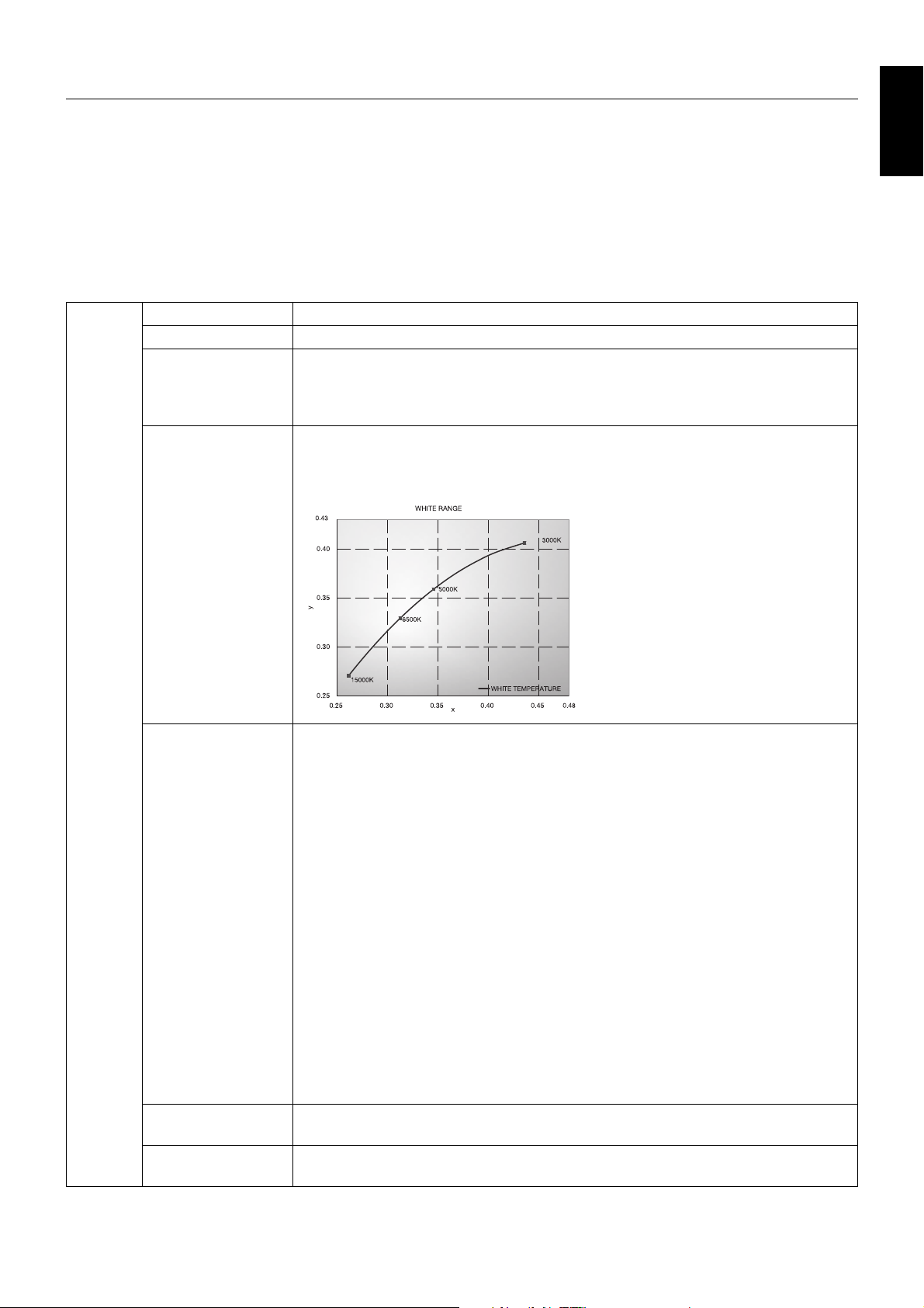
WHITE Adjusts the white color by temperature or xy setting. A lower color temperature will make
the screen reddish and a higher color temperature will make the screen bluish. A stronger
x makes the screen reddish, a stronger y makes it greenish and weak xy makes it a
bluish white.
English
GAMMA Manually select the desired Gamma* correction for the monitor.
The LUT is calculated based on the factory calibration data or GAMMA ADJUST data for
each individual monitor. Six choices are available:
DICOM, LOG LINEAR, L Star, CUSTOM, sRGB and PROGRAMMABLE.
DICOM: DICOM GSDF (Grayscale Standard Display Function).
LOG LINEAR: Luminance changes logarhythmically in response to a linear change of
gradation.
L Star: GAMMA setting for eciRGB_v2 and Lab color space.
CUSTOM: This is displayed as numerical value which you select. The gamma value is
selectable within a range between 0.5 and 4.0, with 0.1 intervals.
sRGB: Setting for sRGB.
PROGRAMMABLE: The Gamma correction (Display Function) can be changed by
using the NEC Display Solutions QA Software. Used for DICOM calibration according to
DICOM Part 14. This setting can be selected only by using the NEC Display Solutions
software when PICTURE MODE is set to PROGRAMMABLE1. Not selectable on the
Advanced menu.
*Gamma - The way luminance is distributed across the intensity spectrum by a monitor,
Gamma is defi ned by the relationship between the signal input voltage and the resulting
intensity of the monitor's light output. A perfect linear device would have a Gamma of 1.0.
A Gamma correction to DICOM Part 14 is used to alter the luminance output of a monitor
to gray steps which appear linear to the human visual system.
CUSTOM VALUE CUSTOM VALUE can be adjusted when CUSTOM is selected as the GAMMA setting.
The gamma value is selectable within a range between 0.5 and 4.0, with 0.1 intervals.
BLACK Adjusts the black luminance. When the selected settings are too low to be displayed,
the indicator on the OSD will turn magenta.
English-19
Page 22
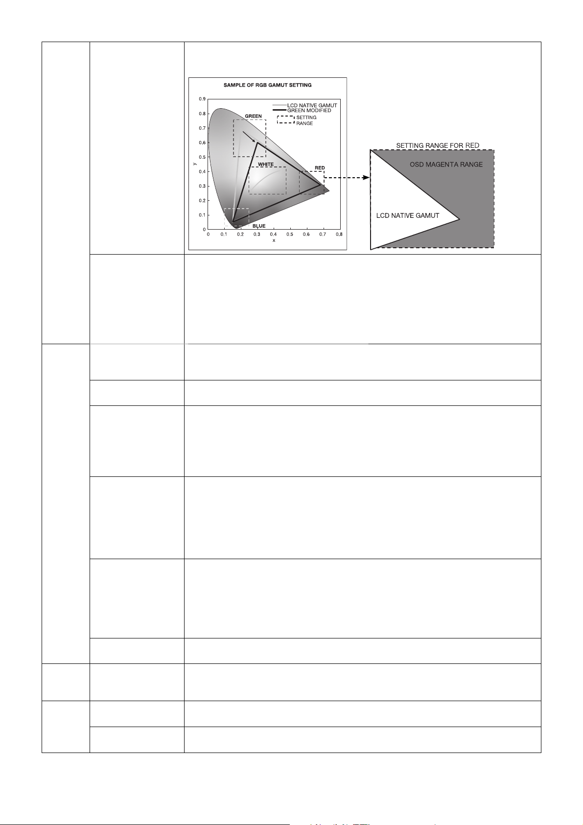
RED
GREEN
Adjusts color gamut. When the selected settings are outside of the LCD gamut, the
indicator on the OSD will turn magenta.
BLUE
UNIFORMITY This function electronically compensates for the slight variations in the white uniformity
level as well as for deviations in color that may occur throughout the display area of
the screen. These variations are characteristic of LCD panel technology. This function
improves the color and evens out the luminance uniformity of the display.
NOTE: Using the UNIFORMITY feature does reduce the overall peak luminance of the
display. If greater luminance is desired over the uniform performance of the display, then
UNIFORMITY should be turned off. A higher number produces a better effect, but may
also reduce CONTRAST RATIO.
Tag2 SHARPNESS This is a digital capability for keeping a crisp image at all signal timings. It continuously
adjusts to maintain as distinct or as soft image as you prefer, and is set independently
according to different timings. Press “LEFT” or “RIGHT” to adjust.
RESPONSE
IMPROVE
COLOR
STABILIZATION
AMBIENT LIGHT
COMP.
(6 - AXIS ADJUST) HUE: Adjusts the hue of each color*
SHORTCUT
CUSTOM
Tag3 DIGITAL LONG
CABLE
(DVI input only)
Tag4 AUTO ADJUST*
1
(Analog input only)
AUTO CONTRAST*
(Analog input only)
*1 This item does not reset by FACTORY PRESET (Tag7).
Turns the Response Improve function on or off. Response Improve may reduce blurring
that occurs in some moving images.
Stabilizes the color of the image. Compensates for a yellow color shift that occurs with
long-term LCD usage.
OFF: No function.
ON: Stabilizes Color.
NOTE: When the function is ON, the lifetime of the LUMINANCE setting level will be
reduced.
Adjusts the luminance and gamma value to be in user setting value including outside
luminance level.
OFF: No ambient light compensation.
1: Compensation based on the infl uence of external light measured during the
calibration.
2: Compensation based on the infl uence of surrounding light with constant
measurement of external light.
2
. The change in color will appear on screen and the
menu color bars will show the amount of adjustment.
SATURATION: Adjusts the color depth of each color*
2
. Press the “RIGHT” button and the
color vividness increases.
OFFSET: Adjusts the color brightness of each color*
2
. Press “RIGHT” button and the
color Brightness increases.
*2: RED, YELLOW, GREEN, CYAN, BLUE and MAGENTA.
You can select the PICTURE MODE which are displayed in PICTURE MODE shortcut
menu.
Compensates for image degradation caused by using a long cable.
A lower number produces less compensation.
Automatically adjusts the Image Position and H.SIZE settings and FINE settings.
Press “SELECT” to activate Auto Adjustment.
1
Adjusts the image displayed for non-standard video inputs. Press “SELECT” to adjust.
Any adjustment requires the image to have white portions.
English-20
Page 23
CONTRAST
(Analog input only)
BLACK LEVEL
Adjusts the image brightness and contrast in relation to the background.
Press “LEFT” or “RIGHT” to adjust.
Adjusts the RGB black level by input signal level.
(Analog input only)
Tag5 H.POSITION Controls Horizontal Image Position within the display area of the LCD.
Press “LEFT” or “RIGHT” to adjust.
V.POSITION Controls Vertical Image Position within the display area of the LCD.
Press “LEFT” or “RIGHT” to adjust.
H.SIZE
(Analog input only)
Adjusts the horizontal size of the screen.
If the “AUTO ADJUST” function do not give you a satisfactory picture setting, a further
tuning can be performed using the “H.SIZE (V.SIZE)” function (dot clock). For this a Moiré
test pattern could be used. This function may alter the width of the picture. Use LEFT/
RIGHT Menu to center the image on the screen. If the H.SIZE (V.SIZE) is incorrectly
calibrated, vertical bands will appear. The image should be homogeneous.
FINE
(Analog input only)
Improve focus, clarity and image stability by increasing or decreasing this setting.
If the “AUTO ADJUST” function and the “H.SIZE” function do not give you a satisfactory
picture setting, a fi ne tuning can be performed using the “FINE” function. For this a Moiré
test pattern could be used. If the Fine value is incorrectly calibrated, horizontal lines will
appear on the display. The image should be homogeneous.
H.RESOLUTION Adjusts the horizontal size by increasing or decreasing the setting.
Press “RIGHT” button to expand the width of the image on the screen.
Press “LEFT” button to narrow the width of the image on the screen.
V.RESOLUTION Adjusts the vertical size by increasing or decreasing the setting.
Press “RIGHT” button to expand the height of the image on the screen.
Press “LEFT” button to narrow the height of the image on the screen.
EXPANSION Sets the zoom method.
FULL: The image is expanded to full screen, regardless of the resolution.
ASPECT: The image is expanded without changing the aspect ratio.
OFF: The image is not expanded.
SIDE BORDER
Adjusts the side black bars color between black and white.
COLOR
1
Tag6 VIDEO DETECT*
Selects the method of video detection when more than one computer is connected.
Press “LEFT” or “RIGHT” to select.
FIRST: When current video input signal is not present, then the monitor searches for a
video signal from the other video input port(s). If the video signal is present in another
port, then the monitor switches the video source input port to the new found video source
automatically. The monitor will not look for other video signals while the current video source
is present.
LAST: When the monitor is displaying a signal from the current source and a new
secondary source is supplied to the monitor, then the monitor will automatically switch to
the new video source. When current video input signal is not present, then the monitor
searches for a video signal from the other video input port. If the video signal is present
another
in
port, then the monitor switches the video source input
port(s)
video source automatically.
NONE: The Monitor will not search the other video input port unless the monitor is
turned on.
English
to the new found
*1 This item does not reset by FACTORY PRESET (Tag7).
English-21
Page 24
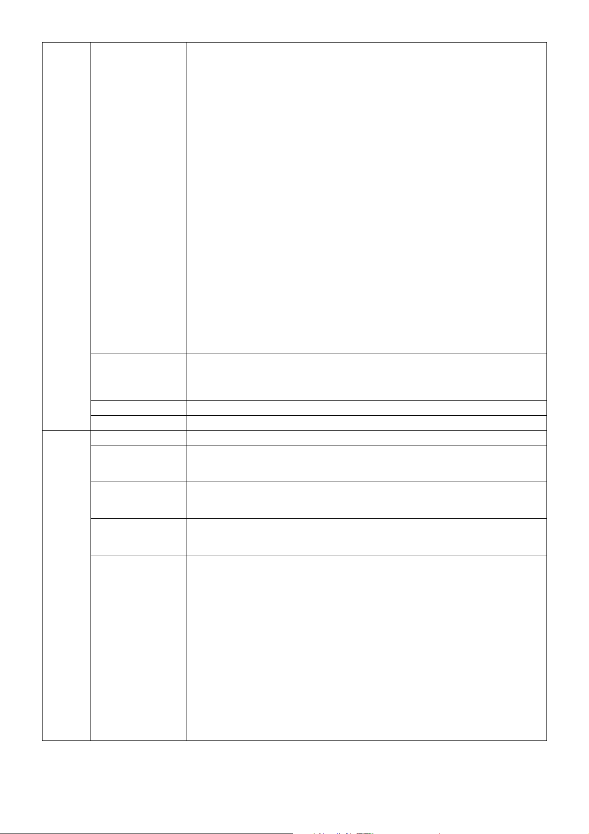
POWER
MANAGEMENT
Sets the energy saving mode.
HUMAN SENSING: HUMAN SENSING has three settings:
OFF: No human sensing.
DEEP: After it is detected that there is no person, the monitor shifts to energy saving
mode automatically.
When a person comes near the monitor again, it resumes from the energy saving
mode and displays the images.
LIGHT: After it is detected that there is no person after a period of time, the monitor
shifts to low luminance mode automatically to reduce the power consumption. When
a person comes near the monitor again, the monitor will automatically return to normal
mode.
SENSITIVITY: SENSITIVITY has three settings.
NORMAL: Detects a person within about 80 cm from the monitor.
NEAR: Sensitivity is decreased.
FAR: Sensitivity is increased.
START TIME: Adjusts the wait time to react. (in minutes)
(SENSING STATUS): Displays the Sensing Status on the bottom of the OSD.
The Sensing Status is only displayed when the OSD cursor is placed on SENSITIVITY.
The Sensing Status does not change when HUMAN SENSING is OFF.
When the monitor detects a person leaving from the monitor, the color gauge passes
the left arrow on the bar.
When the monitor detects a person approaching to the monitor, the color gauge
passes the right arrow on the bar.
NOTE: The monitor may not detect a person in a resting state and shift to energy
saving mode.
The detection range is within about 80cm from the monitor when SENSITIVITY is set
NORMAL.
OFF MODE The Intelligent Power Manager allows the monitor to enter into a power saving mode after
a period of inactivity.
OFF MODE SETTING: Adjusts the ILLUMINANCE value for OFF MODE. Shows
illuminance.
1
LED BRIGHTNESS*
LED COLOR*
Tag7 LANGUAGE*
1
1
Controls the brightness of the power LED on the monitor.
Toggles the power LED on the front between blue or green.
OSD control menus are available in nine languages. Press “LEFT” or “RIGHT” to select.
OSD H.POSITION You can choose where you would like the OSD control image to appear on your screen.
Selecting OSD Location allows you to manually adjust the position of the OSD control
menu left or right.
OSD V.POSITION You can choose where you would like the OSD control image to appear on your screen.
Selecting OSD Location allows you to manually adjust the position of the OSD control
menu up or down.
OSD TURN OFF The OSD control menu will stay on as long as it is use. You can select how long the
monitor waits after the last touch of a button to shut off the OSD control menu.
The preset choices are 10-120 seconds in 5 second increments.
OSD LOCK OUT*
1
This control completely locks out access to all OSD control functions. When attempting
to activate OSD controls while in the Lock Out mode, a screen will appear indicating the
OSD controls are locked out.
There are two types of OSD LOCK OUT:
OSD LOCK OUT with no control: To activate the OSD Lock Out function, press SELECT,
then “RIGHT” button and hold down simultaneously. To deactivate the OSD Lock Out,
press SELECT, then “RIGHT” button and hold down simultaneously while in the OSD
menu. No controls can be adjusted while in the lock out mode.
CUSTOM: Press RESET and EXIT to enter the CUSTOM Menu. Select ENABLE or
DISABLE for POWER KEY INPUT SEL, PICTURE MODE and WARNING (OSD LOCK
OUT) then press SELECT. To Deactivate the OSD Lock Out function, press RESET and
EXIT to bring up the LOCK OUT warning.
Press SELECT, SELECT, LEFT, RIGHT, LEFT, RIGHT, EXIT.
NOTE: OSD control menu will disappear after the time set in OSD TURN OFF or when
EXIT button is pressed.
Quick screen QA test function is not locked out.
*1 This item does not reset by FACTORY PRESET (Tag7).
English-22
Page 25
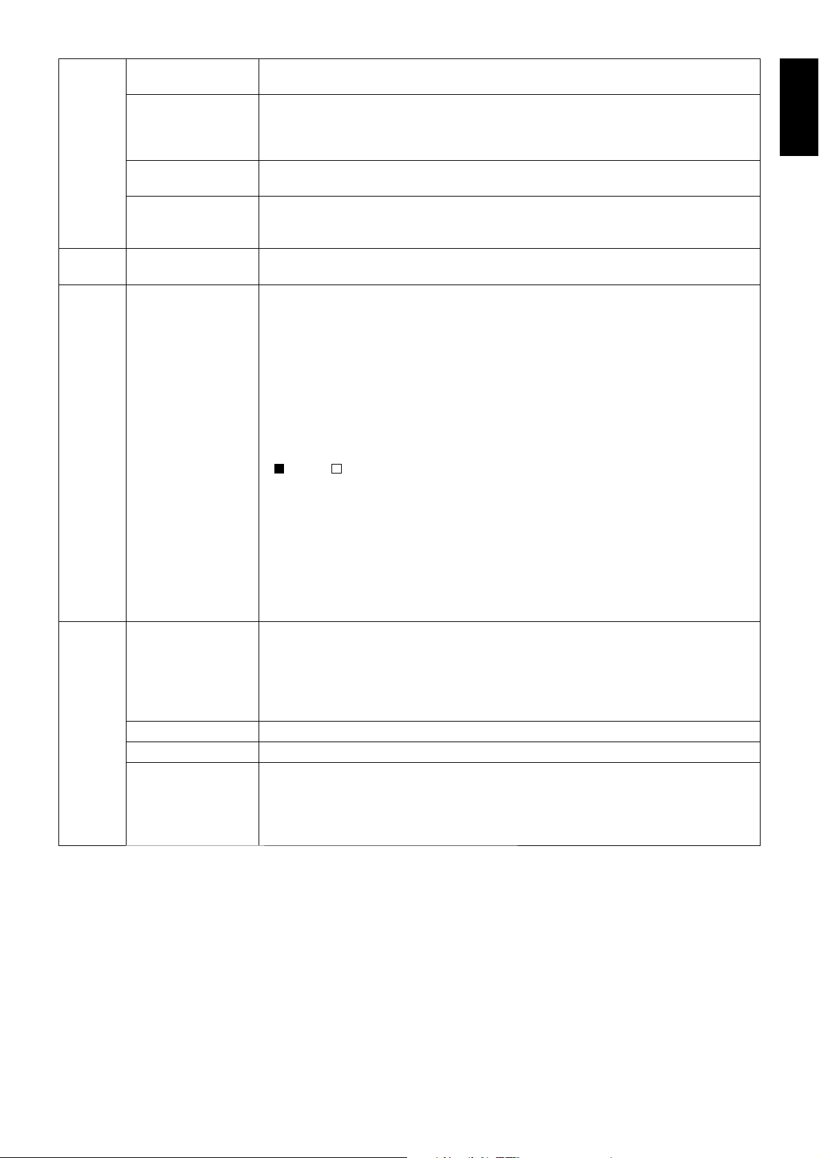
OSD COLOR*
1
“Tag window frame color”, “Item select color” & ”Adjust Window frame color” can be
changed.
BOOT LOGO*
1
The NEC logo is briefl y displayed after the monitor is powered on. This feature can be
turned on or off in the OSD.
Note: If the “EXIT” button is kept pressed while NEC logo is displayed, the BOOT LOGO
menu will appear. It is possible to change the BOOT LOGO setting.
SIGNAL
INFORMATION*
1
FACTORY PRESET*
Signal information can be displayed in the corner of the screen.
Signal information is either “ON/OFF”.
1
Selecting FACTORY PRESET allows you to reset all OSD control settings back to the
factory settings. Highlighting the control to be reset and pressing the RESET button can
reset individual settings.
Tag8 DATE & TIME*
1
Sets the date, time, and daylight saving region. Date & time must be set in order for the
“SCHEDULE” function to operate.
Tag9 SCHEDULE*
1
Programs the GAMMA MEASURE working schedule.
Up to three different schedules can be programmed.
You can select the time and date for GAMMA MEASURE.
QC SCHEDULE:
Use the “Left” or “Right” buttons to select “GAMMA MEASURE only” or “GAMMA
MEASURE and then GAMMA ADJUST”.
Use the down button and “SELECT” to edit schedule.
Use the “Left” or “Right” buttons to move the cursor horizontally.
Use the “Down” or “Up” buttons to up/down schedule number, date and time.
A square mark next to the number of the schedule indicates that the selected schedule
is in effect.
: enable : disable
INTERVAL:
Set the frequency with wich the schedule will be executed (days, weeks, months and
weeks per month).
When you set “0”, the schedule works once.
NOTE: When a schedule overlaps, the schedule from the later would be canceled.
QC RESULT:
Show the past 14 results. The lower the number, it will be the new results.
Use the down button and “SELECT” to show schedule result.
Use the “Down” or “Up” buttons to show other schedule result.
TagA ROTATION OSD:
LANDSCAPE: Display the OSD with landscape mode.
PORTRAIT: Display the OSD with portrait mode.
PICTURE:
OFF: The window image is not rotated.
ON: The window image always rotated.
DDC/CI This function allows the DDC/CI function enable or DISABLE.
BLANK SIGNAL SKIP Skip no signal inputs when you change input signal with INPUT button.
1
INPUT SETTING*
(Analog input only)
Video Band Width: Reduce the visual “noise” level of the input signal. The higher the
number, the greater the effect of reducing the noise. Press “LEFT” or “RIGHT” to select.
Clamp position: Operating your monitor at a non-standard timing may cause images to
appear darker than normal or have color distortion. Use of the Clamp position control will
adjust images to their normal state.
*1 This item does not reset by FACTORY PRESET (Tag7).
English
English-23
Page 26
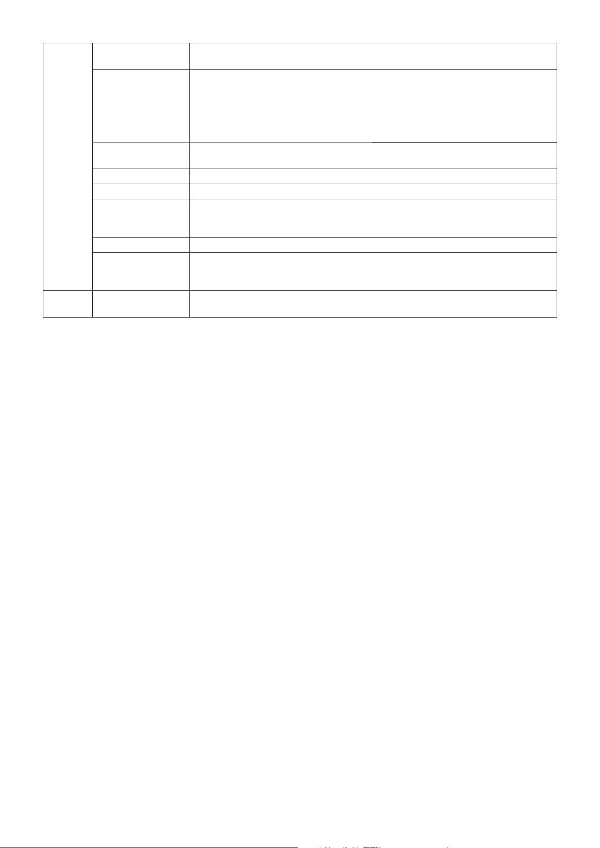
TagB QA TEST*
1
Provides a quick daily visual image quality check of this diagnostic monitor by just using
a button on the monitor. See page 16.
GRAYSCALE MODE This function changes the display image to monochrome.
OFF: The Display Image is COLOR.
MODE1: The signal Input is 8 bit monochrome. The display shows a grayscale image.
This mode uses only the Green channel of an R/G/B input signal.
MODE2: Input is R/G/B Color, but the monitor changes the color space to YUV. The
displayed image will become monochrome. Only Y data passes the R/G/B LUT.
STAND ALONE
CALIBRATION*
1
SELF TEST MODE*
TEMPERATURE*
BACKLIGHT
LIFETIME*
1
Selects the Calibration mode (page 32).
1
Displays an all white screen.
1
Current internal temperature is shown in degrees (C).
The estimated remaining lifetime of the display backlight is indicated here. Backlight
lifetime depends mainly on the desired calibrated settings. The lower the calibrated
setting, the longer the backlight’s estimated lifetime.
1
HOURS RUNNING*
ILLUMINANCE*
1
Shows total running time.
Shows the lux value calculated by the ambient light sensor. The ILLUMINANCE value is
dependent on the type and position of light source. It may differ from the value measured
by the illuminance meter.
TagC INFORMATION*
1
Provides information about the current display resolution. Technical data, including the preset
timing currently being used and the horizontal and vertical frequencies is also displayed.
*1 This item does not reset by FACTORY PRESET (Tag7).
English-24
Page 27
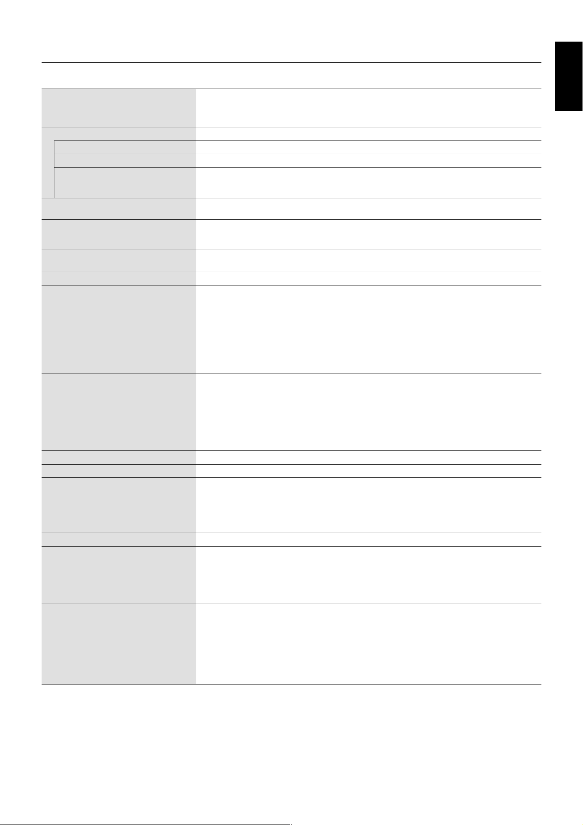
Specifi cations
Monitor Specifi cations MultiSync MDC212C2 Notes
LCD Module Diagonal:
Viewable Image Size:
Native Resolution (Pixel Count):
54.0 cm/21.3 inches
54.0 cm/21.3 inches
1600 x 1200
Input Signal
DisplayPort: DisplayPort Connector: Digital RGB Applicable to HDCP
DVI: DVI-D 24pin: Digital RGB DVI, applicable to HDCP
VGA: 15pin Mini D-sub: Analog RGB
Sync
Display Colours 1,073,741,824 (DisplayPort 10 bit)
16,777,216 (DVI)
2
Synchronization Range Horizontal:
Vertical:
Viewing Angle Left/Right:
Up/Down:
31.5 kHz to 94.0 kHz, 99.5 kHz*
31.5 kHz to 92.0 kHz, 99.5 kHz*
50 Hz to 85 Hz
±89° (CR > 10)
±89° (CR > 10)
(Analog)
2
(Digital)
Image Formation Time 8 ms (Gray to gray Typ)
Resolutions Supported (Some systems may
not support all modes listed).
640 x 480*
720 x 400*
800 x 600*
1024 x 768*
1280 x 720*
1280 x 960*
1280 x 1024*
1
at 60 Hz to 85 Hz
1
at 70 Hz to 85 Hz
1
at 56 Hz to 85 Hz
1
at 60 Hz to 85 Hz
1
at 50 Hz to 60 Hz
1
at 60 Hz to 85 Hz
1
at 60 Hz to 85 Hz
1600 x 1200 at 60 Hz to 75 Hz (Analog)
1600 x 1200 at 60 Hz (Digital).............................. NEC DISPLAY SOLUTIONS cites recommended
1200 x 1600 at 60 Hz resolution for optimal display performance.
Active Display Area Landscape: Horiz.:
Vert.:
Portrait: Horiz.:
Vert.:
USB Hub I/F:
Port:
432 mm/17.0 inches
324 mm/12.8 inches
324 mm/12.8 inches
432 mm/17.0 inches
USB Specifi cation Revision 3.0
Upstream 1
Downstream 3
Load Current:
Maximum 0.9 A per port
Power Supply AC 100-240 V ~ 50/60 Hz
Current Rating 1.0 - 0.6 A (with option)
Dimensions Landscape:
466.4 mm (W) x 374.6 - 524.6 mm (H) x 227.6 mm (D)
18.4 inches (W) x 14.7 - 20.7 inches (H) x 9.0 inches (D)
Portrait:
359.0 mm (W) x 484.0 - 580.0 mm (H) x 227.6 mm (D)
14.1 inches (W) x 19.1 - 22.8 inches (H) x 9.0 inches (D)
Height Adjustment:
150 mm / 5.9 inches (Landscape orientation)
96 mm / 3.8 inches (Portrait orientation)
Weight 8.0 kg (17.6 lbs)
Sensor Accuracy and Repeatability
Front Sensor Accuracy*
Repeatability:
Ambient Sensor Accuracy:
2
:
+/-10% (Lv>10cd/m
+/-2% (Standard Deviation)
2
), +/-1cd/m2 (10cd/m2 ≧ Lv>2cd/m2), +/-0.5cd/m2 (Lv ≦ 2cd/m2)
+/-10% (Light source: White-LED Diffusion light, Distance:
60 cm, Angle: 0 +/-10 degrees from the vertical axis of
Repeatability:
the ambient sensor).
+/-5% (Same as Accuracy conditions).
Environmental Considerations
Operating Temperature:
Humidity:
Altitude:
Atmospheric pressure:
Storage Temperature:
Humidity:
Altitude:
Atmospheric pressure:
At 20-25 degrees, Target Luminance 180 cd/m2, Factory measurement value.
*1 Interpolated Resolutions: When resolutions are shown that are lower than the pixel count of the LCD module, text may appear different. This is normal and
necessary for all current fl at panel technologies when displaying non-native resolutions full screen. In fl at panel technologies, each dot on the screen is actually
one pixel, so to expand resolutions to full screen, an interpolation of the resolution must be done.
*2 1200 x 1600 resolution only.
5°C to 35°C/41°F to 95°F
20% to 80%
-1247 to 16,404 Feet/-380 to 5,000 m
540 hPa to 1060 hPa
-20°C to 60°C/-4°F to 140°F
10% to 85%
-1247 to 40,000 Feet/-380 to 12,192 m
200 hPa to 1060 hPa
NOTE: Technical specifi cations are subject to change without notice.
Active matrix; thin fi lm transistor (TFT) liquid crystal
display (LCD); 0.270 mm dot pitch; 440 cd/m
luminance; 180 cd/m
2
calibrated luminance;
2
max
1500:1 contrast ratio (typical).
0.7 Vp-p/75 ohm
Separate sync.TTL level Positive/Negative
Composite sync.TTL level Positive/Negative
Depends on display card used.
Automatically
Automatically
Automatically
English
English-25
Page 28

Features
DisplayPort: DisplayPort is designed to be the future-ready, scalable solution for high performance digital display connectivity. It
enables the highest resolutions, the fastest refresh rates and deepest color depths over standard cables.
DVI-D: The digital-only subset of DVI ratifi ed by the Digital Display Working Group (DDWG) for digital connections between
computers and displays. As a digital-only connector, analog support is not provided off a DVI-D connector. As a DVI-based
digital only connection, only a simple adapter is necessary for compatibility between DVI-D and other DVI-based digital
connectors such as DFP and P&D.
P&D (Plug and Display): The VESA standard for digital fl at panel monitor interfaces. It is more robust than DFP since it
allows for other options off a signal connector (options like USB, analog video and IEEE-1394-995). The VESA committee
has recognized that DFP is a subset of P&D. As a DVI-based connector (for the digital input pins), only a simple adapter is
necessary for compatibility between P&D and other DVI-based digital connector such as DVI and DFP.
Pivoting Stand: Allows users to adjust the monitor to the orientation that best fi ts their application, either Landscape orientation
for wide documents, or Portrait orientation for the ability to preview a full page on one screen at one time. The Portrait
orientation is also perfect for full screen video conferencing.
Reduced Footprint: Provides the ideal solution for environments with space constraints that still require superior image quality.
The monitor’s small footprint and low weight allow it to be moved or transported easily from one location to another.
Natural Color Matrix: Combines Six-axis color control and the sRGB standard. Six-axis color control permits color adjustments
via six axes (R, G, B, C, M and Y) rather than through the three axes (R, G and B) previously available. The sRGB standard
provides the monitor with a uniform color profi le. This assures that the colors displayed on the monitor are exactly the same as
on the color printout (with sRGB supporting operating system and sRGB printer). This allows you to adjust the colors on your
screen and customise the color accuracy of your monitor to a variety of standards.
OSD (On-Screen Display) Controls: Allow you to quickly and easily adjust all elements of your screen image via simple to use
on-screen menus.
Plug and Play: The Microsoft
the monitor to send its capabilities (such as screen size and resolutions supported) directly to your computer, automatically
optimizing display performance.
Intelligent Power Manager System: Provides innovative power-saving methods that allow the monitor to shift to a lower power
consumption level when on but not in use, saving two-thirds of your monitor energy costs, reducing emissions and extending the
useful life of the monitor’s backlights.
Multiple Frequency Technology: Automatically adjusts monitor to the display card’s scanning frequency, thus displaying the
resolution required.
FullScan Capability: Allows you to use the entire screen area in most resolutions, signifi cantly expanding image size.
Wide Viewing Angle Technology: Allows you to be able to see the monitor from any angle (178°) from any orientation —
Portrait or Landscape. Provides full 178° viewing angles either up, down, left or right.
VESA Standard Mounting Interface: Allows users to connect your MultiSync monitor to any VESA standard third party
mounting arm or bracket.
UNIFORMITY: This feature compensates for slight variations in the white uniformity level that may occur on the screen and
improves the color and evens out the luminance uniformity of the display.
Response Improve: Improved gray to gray response.
Adjustable stand with pivot capability: Adds fl exibility to your viewing preferences.
Front sensor: Detects screen luminance changes over time. Used for luminance stabilization, standalone (Self Calibration,
Gamma Adjust, DICOM Measurement) and network (Gamma Adjutst, DICOM Measurement) controlled calibrations and
conformance tests.
Quick screen QA test function: Provides a quick daily visual image quality check of this diagnostic monitor by just using a
button on the monitor.
HDCP (High-bandwidth Digital Content Protection): HDCP is a system for preventing illegal copying of video data sent
over a digital signal. If you are unable to view material via the digital input, this does not necessarily mean the display is not
functioning properly. With the implementation of HDCP, there may be cases in which certain content is protected with HDCP and
might not be displayed due to the decision/intention of the HDCP community (Digital Content Protection, LLC).
USB 3.0 hub: USB 3.0 hub for faster communication with the workstation, e.g. using a USB-stick.
Human Sensor: Shifts to a lower power consumption level when a person leaves the monitor, saving your monitor energy
costs. When a person comes near the monitor, the monitor will automatically return to normal mode.
This feature detects infrared radiations from human body without interfering with other devices.
®
solution with the Windows® operating system facilitates setup and installation by allowing
English-26
Page 29

Troubleshooting
No picture
• The signal cable should be completely connected to the display card/computer.
• The display card should be completely seated in its slot.
• The front power button and computer power switch should be in the ON position.
• Check to make sure that a supported mode has been selected on the display card or system being used.
(Please consult display card or system manual to change graphics mode.)
• Check the monitor and your display card with respect to compatibility and recommended settings.
• Check the signal cable connector for bent or pushed-in pins.
• The monitor does not support a DisplayPort converter adapter.
• Check whether the computer can support the power requirements of the display controller.
• Check the signal input.
• If the front LED is dark green, check the status of the OFF MODE (see page 24) or HUMAN SENSING or SENSITIVITY
(see page 24).
Power Button does not respond
• Unplug the power cord of the monitor from the AC outlet to turn off and reset the monitor.
Image Persistence
• Image persistence is when a residual or “ghost” image of a previous image remains visible on the screen. Unlike CRT
monitors, LCD monitors’ image persistence is not permanent, but constant images being displayed for a long period
of time should be avoided. To alleviate image persistence, turn off the monitor for as long as the previous image was
displayed. For example, if an image was on the monitor for one hour and a residual image remains, the monitor should
be turned off for one hour to erase the image.
NOTE: As with all personal display devices, NEC DISPLAY SOLUTIONS recommends using a moving screen saver at
regular intervals whenever the screen is idle or turning off the monitor when not in use.
English
Picture is discolored
• First, use the front POWER button to turn off the monitor. Then use the POWER button turn the monitor on while holding
RESET and SELECT (INPUT) buttons at the same time. This will reset all color parameters to the factory setting. This
reset will take about 10 seconds and then the factory settings screen is displayed.
Message “OUT OF RANGE” is displayed (screen is either blank or shows rough images only)
• Image is displayed only roughly (pixels are missing) and OSD warning “OUT OF RANGE” is displayed: Either signal
clock or resolution is too high. Choose one of the supported modes.
• OSD warning “OUT OF RANGE” is displayed on a blank screen: Signal frequency is out of range. Choose one of the
supported modes.
Image is unstable, unfocused or swimming is apparent
• Signal cable should be completely attached to the computer.
• Use the OSD Image Adjust controls to focus and adjust display by increasing or decreasing the fi ne adjustment.
When the display mode is changed, the OSD Image Adjust settings may need to be readjusted.
• Check the monitor and your display card with respect to compatibility and recommended signal timings.
• If your text is garbled, change the video mode to non-interlace and use 60Hz refresh rate.
LED on monitor is not lit (no green, blue or amber color can be seen)
• Power Switch should be in the ON position and power cord should be connected.
• Increase LED BRIGHTNESS adjustment.
Picture is not as bright
• LCD luminance degradation occurs due to long-term usage or extreme cold and high temperature conditions.
Display image is not sized properly
• Use the OSD Image Adjust controls to increase or decrease the Coarse adjustment.
• Check to make sure that a supported mode has been selected on the display card or system being used.
(Please consult display card or system manual to change graphics mode.)
• Adjust H.RESOLUTION or V.RESOLUTION in Tag5 advanced OSD menu.
No Video
• If no video is present on the screen, turn the Power button off and on again.
• Make certain the computer is not in a power-saving mode (touch the keyboard or mouse).
• Some display cards do not output video signal when monitor is turned OFF/ON or disconnect/connect from the AC power
cord under low resolution with DisplayPort.
English-27
Page 30

Self Diagnosis
• The LCD display is equipped with the ability to self diagnose abnormalities. When the LCD detects a problem, the LED
on the front fl ashes in a pattern of long and short blinks, depending on the type of problem detected.
• If the LED signals a problem, please refer service to qualifi ed personnel for service.
USB Hub does not operate
• Check to make sure the USB cord is properly connected. Refer to your USB device User’s Manual.
• Turn the Power button off and on again.
Human sensor does not work
• Make sure there is human presence in front of the monitor.
• Make sure there is no object in front of Human sensor.
• Make sure there is no equipment which radiating infrared rays in front of monitor.
• The monitor may not detect a person in a resting state or wearing a mask.
English-28
Page 31
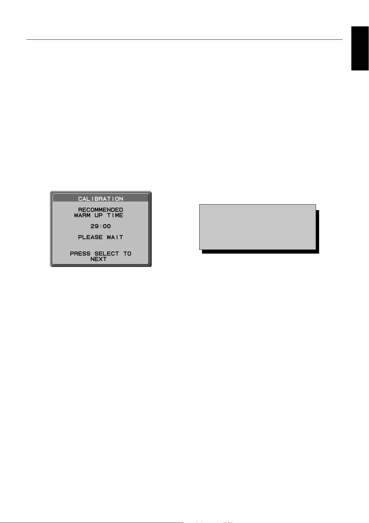
STAND-ALONE CALIBRATION
Stand alone calibration can recalibrate the display without using a computer by the integrated front sensor or connecting an
external sensor. There are 4 functions in STAND-ALONE CALIBRATION.
• Self Calibration: Manually adjust the integrated front sensor with an external near range color analyzer reference, which is
traceable to a primary standards laboratory.
• Gamma Adjust: Recalibrates Gamma data by the integrated front sensor.
• GAMMA Measurement: Measures GAMMA error ratio.
• AMBIENT SENSOR CALIBRATION: To manually adjust the integrated ambient light sensor with an external color analyzer
reference, which is traceable to a primary standards laboratory.
NOTE: Stand before proper Stand-Alone calibration can be performed, the display should warm-up for a minimum of
30 minutes. If Stand-Alone calibration is started before the monitor is warmed up, a warning will appear on-screen
(Figure A.1).
NOTE: Refer to the KEY MAP (Figure A.2) to adjust the settings for calibration.
Stand-Alone calibration should be performed in either portrait or landscape orientation.
NOTE: To start calibration without a computer, perform the following steps.
When the “NO SIGNAL” message appears on screen, press the “LEFT” and then “RIGHT” buttons and hold them
down simultaneously. The CALIBRATION menu will appear.
NOTE: The image may be distorted when signal input is changed while calibrating.
KEY MAP
UP/DOWN: Changes from setting to setting
LEFT/RIGHT: Changes the setting selection
(ie...SELF or COPY)
SELECT: Moves to the next step of calibration
EXIT: Moves back one step of calibration
English
Figure A.2
Figure A.1
CAUTION: Please use a properly-managed external near range color analyzer. If there is any doubt about the result of
the Stand-Alone calibration result, please contact your supplier.
English-29
Page 32
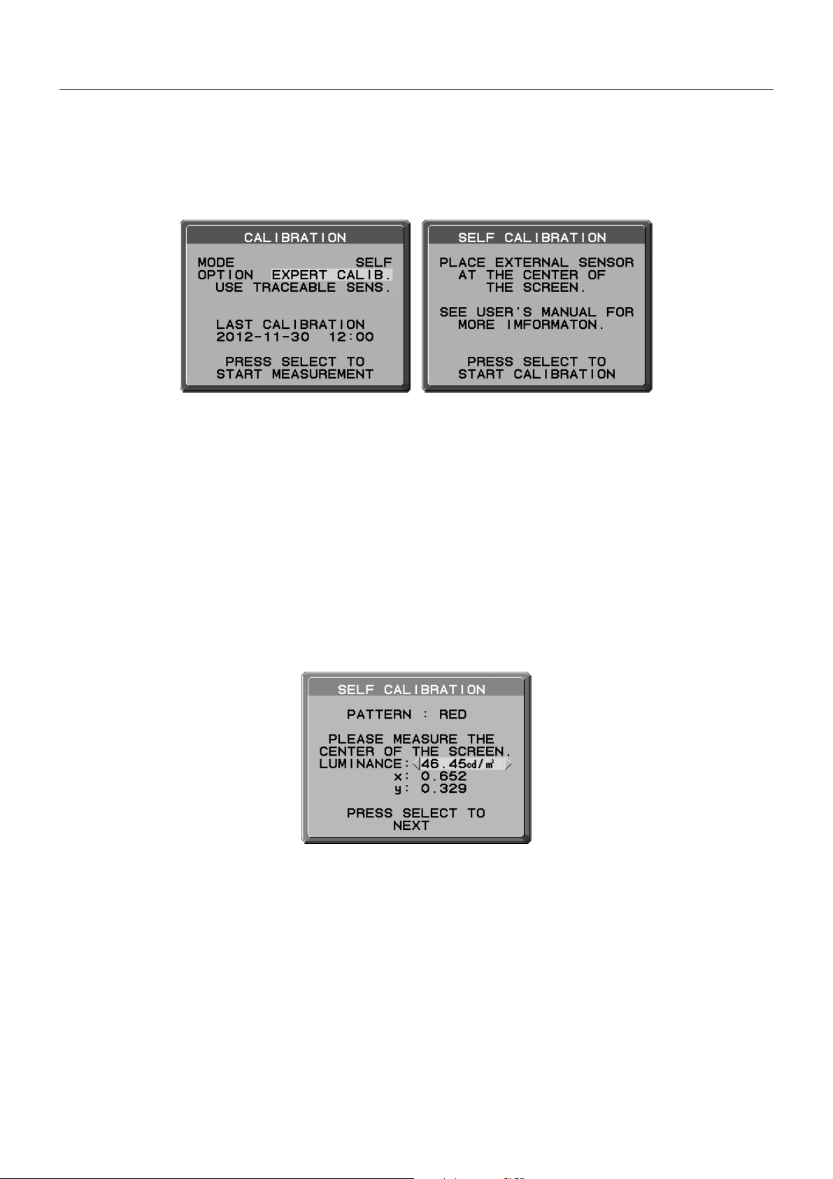
Self Calibration
Manually adjust the integrated front sensor with an external near range color analyzer reference, which is traceable to a primary
standards laboratory. All PICTURE MODES are updated when Self Calibration is performed.
NOTE: An external near range color analyzer, which is traceable to a primary standards laboratory, is required.
1. To show the CALIBRATION menu, select STAND ALONE CALIBRATION in the advanced menu (page 24), or press the
“LEFT” and then “RIGHT” buttons and hold them down simultaneously when the “NO SIGNAL” message appears on screen.
2. Use “LEFT” or “RIGHT” to select SELF in the MODE selection (Figure S.1). Press SELECT to go to the next section.
Figure S.1 Figure S.2
3. The procedure will ask for the external near range color analyzer to be placed on the center of the display panel
(Figure S.2). Place the external near range color analyzer in the center of the display panel, then press SELECT.
NOTE: Place an external near range color analyzer fl at against the LCD to avoid any infl uence of ambient light.
DO NOT press an external near range color analyzer against the display panel.
4. The measument screen will be displayed. Measure the luminance and chromaticity value of the center of the display by
using the external near range color analyzer. Input the measured value to LUMINANCE and chromaticity by using the control
keys, then press SELECT (Figure S.3).
5. According to the message window, repeat the measurement of luminance and chromaticity and input the measured value
until the procedure is completed.
NOTE: If chromaticity value is not measured by your external near range color analyzer, only input the luminance value and
press SELECT.
6. GAMMA Measurement is then executed automatically. After completing GAMMA Measurement, you can set DATE and TIME
by using control keys.
Figure S.3
English-30
Page 33
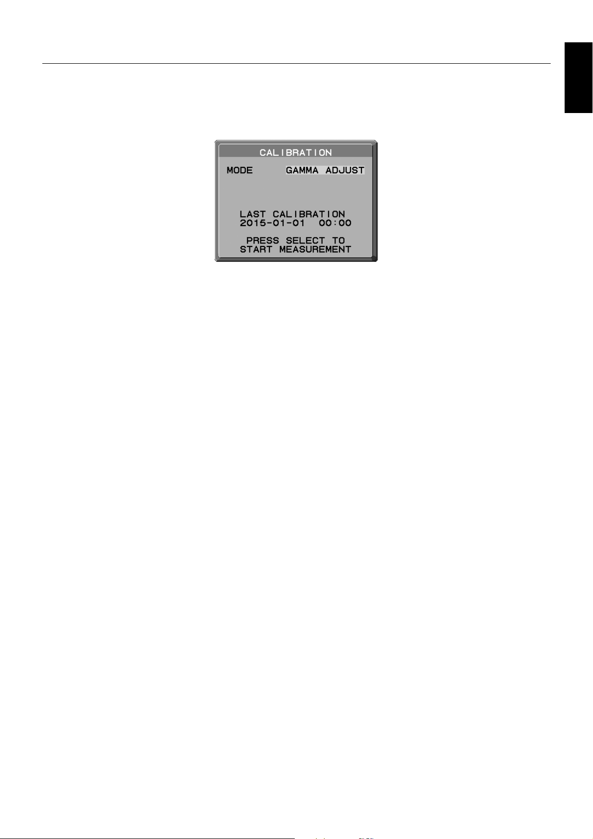
Gamma Adjust
By using the integrated front sensor, Gamma Adjust recalibrates the LCD gamma. Gamma Adjust is recommended if MAX
GSDF ERROR exceeds the medical standards. All PICTURE MODES are updated when Gamma Adjust is performed.
1. To show the CALIBRATION menu, select the STAND ALONE CALIBRATION in the advanced menu (page 24).
2. Select GAMMA ADJUST in the MODE selection (Figure 1).
3. Press SELECT to start the calibration. This may take several minutes depending on user setting.
Figure 1
4. GAMMA Measurement is continuously executed automatically.
After completing GAMMA Measurement, you can set DATE and TIME using control keys.
English
English-31
Page 34
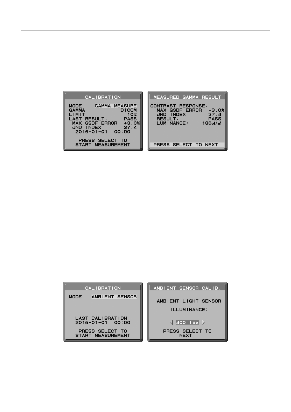
GAMMA MEASURE
DICOM PART14 can be performed by using the integrated front sensor.
1. To show the CALIBRATION menu, select the STAND ALONE CALIBRATION in the advanced menu (page 29).
2. Use “LEFT” or “RIGHT” to select GAMMA MEASURE in the MODE selection (Figure D.1).
3. Select the GAMMA that you want to measure and press SELECT.
NOTE: This function is effective only if GAMMA (Advanced menu Tag1) is DICOM or PROGRAMMABLE.
4. After the GAMMA MEASURED RESULT message appears (Figure D.2). You can set DATE and TIME using control keys,
and press SELECT.
5. To end the calibration mode, press “EXIT”.
Figure D.2Figure D.1
NOTE: If RESULT is FAIL, please perform GAMMA ADJUST.
AMBIENT SENSOR CALIBRATION
AMBIENT SENSOR CALIBRATION can manually calibrate the ambient light sensor.
This function is effective when AMBIENT LIGHT COMP. (page 20) setting is 1 or 2.
Please perform AMBIENT SENSOR CALIBRATION in the following cases:
• The usage environment has changed
NOTE: Please execute the Ambient Sensor Calibration under indirect light.
AMBIENT SENSOR CALIBRATION requires an illuminance meter and a telescopic luminance meter.
1. In power off mode, measure the luminance value of the center of the screen by the telescopic luminance meter. If a
telescopic luminance meter is not available, go to next step.
2. Turn on the display. After a lapse of 30 minutes, select AMBIENT SENSOR in the calibration mode (Figure AS.1).
For a proper calibration, the display should warm-up for a minimum of 30 minutes. If AMBIENT SENSOR CALIBRATION is
started before the display is warmed up, a warning message will appear on-screen.
3. AMBIENT Calibration message appears. Press SELECT.
4. Input the value measured by the illuminance meter which should be installed at the same angle as the display (Figure AS.5).
Input the value by using the control keys, then press SELECT (Figure AS.2).
Figure AS.1
Figure AS.2
English-32
Page 35
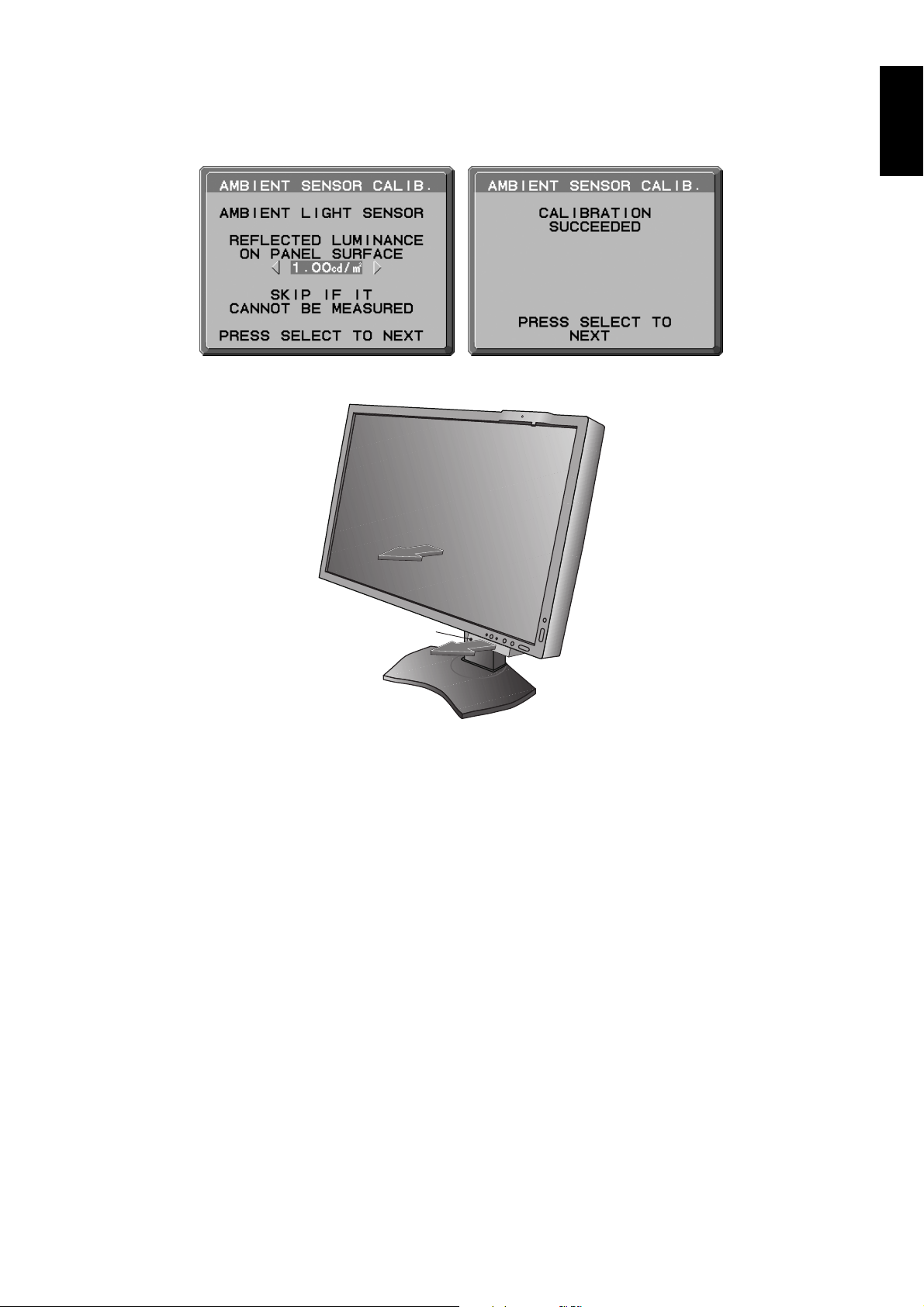
5. Input the value measured at 1, and press SELECT (Figure AS.3).
When not having measured, press SELECT without changing the value.
6. After the CALIBRATION SUCCEEDED message appears (Figure AS.4), press SELECT.
You can set DATE and TIME by using control keys, and press SELECT.
7. To end the calibration mode, press EXIT.
Figure AS.4Figure AS.3
English
Illuminance meter
Figure AS.5
English-33
Page 36
Manufacturer’s Recycling and Energy Information
NEC DISPLAY SOLUTIONS is strongly committed to environmental protection and sees recycling as one of the company’s
top priorities in trying to minimize the burden placed on the environment. We are engaged in developing environmentallyfriendly products, and always strive to help defi ne and comply with the latest independent standards from agencies such as
ISO (International Organisation for Standardization) and TCO (Swedish Trades Union).
Disposing of your old NEC product
The aim of recycling is to gain an environmental benefi t by means of re-use, upgrading, reconditioning or reclamation of
material. Dedicated recycling sites ensure that environmentally harmful components are properly handled and securely
disposed. To ensure the best recycling of our products, NEC DISPLAY SOLUTIONS offers a variety of recycling procedures
and gives advice on how to handle the product in an environmentally sensitive way, once it has reached the end of its life.
All required information concerning the disposal of the product and country-specifi c information on recycling facilities can be
found on our following websites:
http://www.nec-display-solutions.com/greencompany/ (in Europe),
http://www.nec-display.com (in Japan) or
http://www.necdisplay.com (in USA).
Energy Saving
This monitor features an advanced energy saving capability. When a VESA Display Power Management Signalling (DPMS)
Standard signal is sent to the monitor, the Energy Saving mode is activated. The monitor enters a single Energy Saving mode.
Mode Power consumption LED colour
Normal Operation (with option) Approx. 54 W Green or blue
Energy Saving Mode Less than 6 W Amber
Off Mode Less than 0.3 W Unlit
For additional information visit:
http://www.necdisplay.com/ (in USA)
http://www.nec-display-solutions.com/ (in Europe)
http://www.nec-display.com/global/index.html (Global)
WEEE Mark (European Directive 2012/19/EU)
Disposing of your used product:
In the European Union
EU-wide legislation as implemented in each Member State requires that used electrical and electronic products
carrying the mark (left) must be disposed of separately from normal household waste. This includes monitors
and electrical accessories, such as signal cables or power cords. When you dispose of such products, please
follow the guidance of your local authority or ask the shop where you purchased the product, or if applicable,
follow applicable legislation or agreement you may have. The mark on electrical and electronic products may
only apply to the current European Union Member States.
Outside the European Union
If you wish to dispose of used electrical and electronic products outside the European Union, please contact your local authority
and ask for the correct method of disposal.
NEC Display Solutions, Ltd.
4-28, Mita 1-chome, Minato-ku, Tokyo,
Japan
NEC Display Solutions of America, Inc.
500 Park Blvd. Suite 1100 Itasca,
Illinois 60143
USA
Phone: +1-630.467.3000
Fax: +1-630.467.3010
English-34
NEC Display Solutions Europe GmbH
Landshuter Allee 12-14
D-80637 Muenchen
Germany
Phone: +49(0)89/99699-0
Fax: +49(0)89/99699-500
3rd Edition, August 2016
 Loading...