

NEC MT1056 Installation Guide

NEC Solutions (America), Inc.
Visual Systems
MT1055/1056 Installation Data
with Standard Zoom Lens
Contents
Product Description, Lens Specs, Notes and Formulas Page 1
Projection Distances and Screen Sizes
Ceiling Mount Installation
Desktop Setup
Cabinet Dimensions
Top, Front and Right Side
Bottom, Back and Left Side
Ceiling Mount Dimensions
Control Codes
Product Description
Type: 3 panel, 1.3” p-Si TFT w/MLA LCD projector Dimensions: 11.1”(W) x 4.8”(H) x 14.9”(D)
Native Resolution: 1024 x 768 Weight: 13.3 lbs
Brightness: 3000 ANSI Lumens (2600 for MT1055) Manual Focus/Manual Zoom
Std Lens Specifications
Throw Ratio: 1.8 – 2.2 : 1 (approx) Focal Length: 49.3 – 59.3mm
Offset Angle: 9.8 – 10.5(Wide)/8.2 – 8.6(Tele) F/#: 1.8 – 2.2
Screen Sizes: 30” – 300” Diagonal
Notes
For screen sizes not indicated on the projection tables, use the formulas below.
If the figures on the tables do not match the results of formulas, use the figures in the table.
The ceiling must be strong enough to support the LCD projector and the installation must be in accordance with any local
building codes.
• All calculations are based on 4:3 aspect ratio.
• Distances are in inches, for millimeters multiply by 25.4.
• Distances may vary ±5%.
Formulas
Units: Inches (for millimeters multiply final number by 25.4)
Definitions:
H = Horizontal Screen Width (4:3)
V = Vertical Screen Height (4:3)
B = Vertical distance between lens center and screen center
C = Throw distance
D = Vertical distance between lens center and screen top (screen bottom for desktop application)
α = Throw Angle
Projection Formulas:
B = 0.3193H H = Screen Diagonal x 4/5
C (wide) = 1.8588H – 3.171 V = Screen Diagonal x 3/5
C (tele) = 2.2299H – 2.710 Screen Diagonal = H x 5/4
D = 0.0557H
α (wide) = tan
α (tele) = tan
-1
-1
Screen Formulas (4:3):
(B/C(wide))
(B/C(tele))
v 3.0
Page 2
Page 3
Page 4
Page 5
Page 6
Page 7
Page 1
NEC Solutions (America), Inc.
Visual Systems
MT1055/1056 Installation Data
with Standard Zoom Lens v 3.0
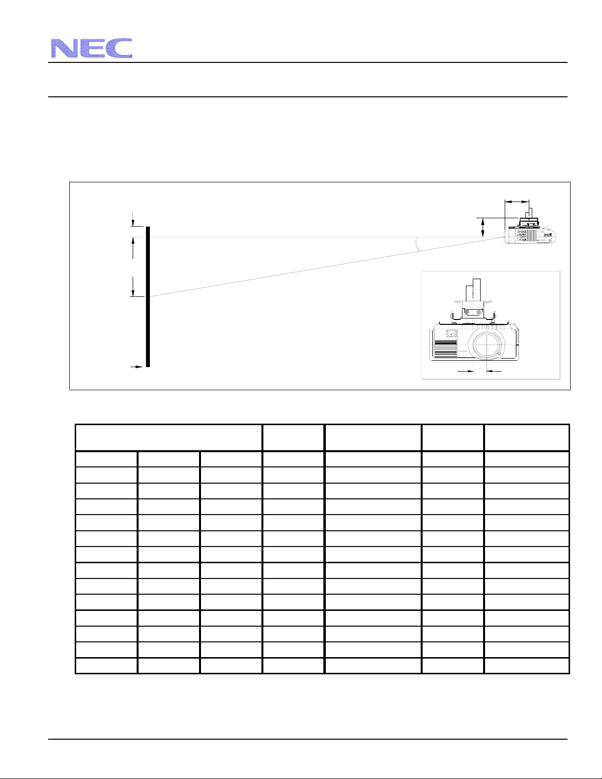
Projection Distance and Screen Size for Ceiling Mount
The following shows the proper relative position of the projector and screen. Refer to the table for installation data.
Distances are in inches. For millimeters multiply by 25.4.
Ceiling Mount Installation
7.5"
Screen Top
Lens Ctr
D
C
Throw Distance
α
5.8"
B
Screen Ctr
Scrn Bottom
`
@
AC IN
Lens Offset from
Mounting Pipe
1.7"
Distance Chart
Screen Size
Diagonal Width Height wide - tele wide - tele
40" 32" 24" 10.2" 56.3" - 68.6" 1.8" 10.3° - 8.5°
60" 48" 36" 15.3" 86.1" - 104.3" 2.7" 10.1° - 8.4°
67" 53.6" 40.2" 17.1" 96.5" - 116.8" 3.0" 10.1° - 8.3°
72" 57.6" 43.2" 18.4" 103.9" - 125.7" 3.2" 10.0° - 8.3°
84" 67.2" 50.4" 21.5" 121.7" - 147.1" 3.7" 10.0° - 8.3°
90" 72" 54" 23.0" 130.7" - 157.8" 4.0" 10.0° - 8.3°
100" 80" 60" 25.5" 145.5" - 175.7" 4.5" 10.0° - 8.3°
120" 96" 72" 30.6" 175.3" - 211.4" 5.4" 9.9° - 8.3°
150" 120" 90" 38.3" 219.9" - 264.9" 6.7" 9.9° - 8.2°
180" 144" 108" 46.0" 264.5" - 318.4" 8.0" 9.9° - 8.2°
210" 168" 126" 53.6" 309.1" - 371.9" 9.4" 9.9° - 8.2°
240" 192" 144" 61.3" 353.7" - 425.4" 10.7" 9.8° - 8.2°
270" 216" 162" 69.0" 398.3" - 479.0" 12.0" 9.8° - 8.2°
300" 240" 180" 76.6" 443.0" - 532.5" 13.4" 9.8° - 8.2°
Note: For screen sizes not indicated on the projection tables, use the formulas on page 1.
BCD
α
Page 2
NEC Solutions (America), Inc.
Visual Systems
MT1055/1056 Installation Data
with Standard Zoom Lens v 3.0
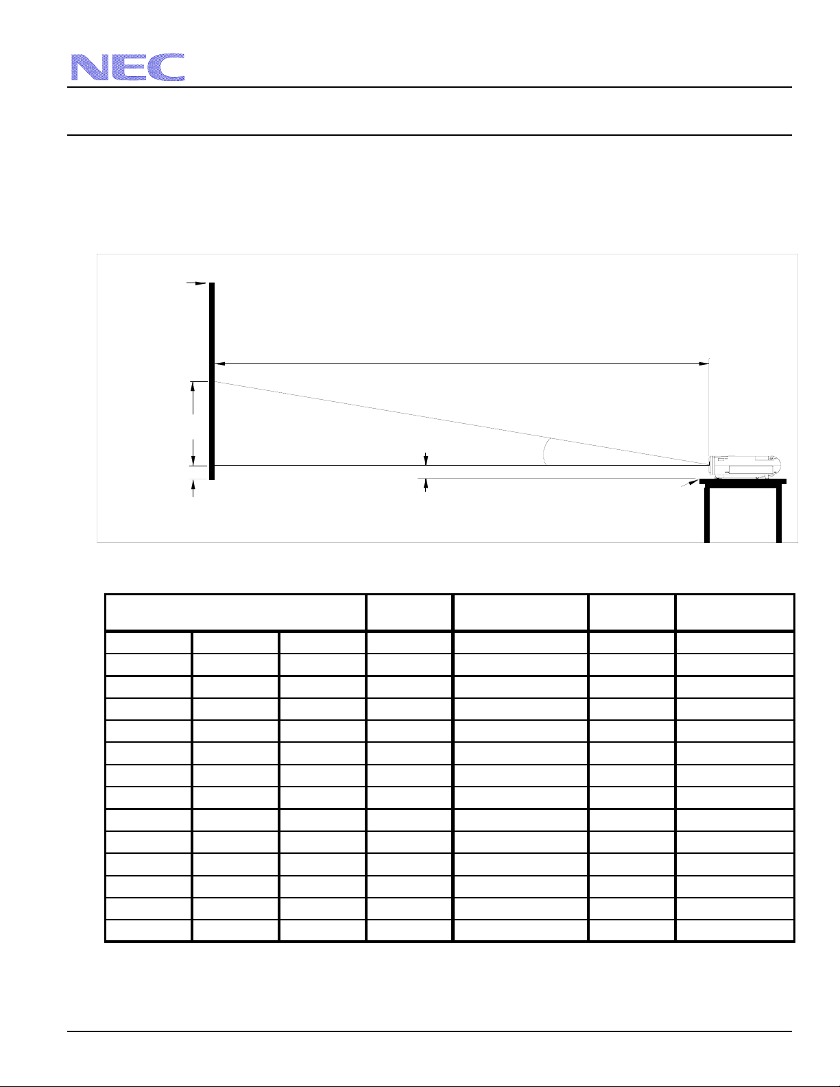
Projection Distance and Screen Size for Desktop
The following diagram shows the relationship between projector position and the screen.
Distances are in inches. For millimeters multiply by 25.4.
Desktop Setup
Screen Top
C
Screen Ctr
B
Throw Distance
Lens Ctr
Scrn Bottom
D
2.89"
Distance Chart
Screen Size
Diagonal Width Height wide - tele wide - tele
40" 32" 24" 10.2" 56.3" - 68.6" 1.8" 10.3° - 8.5°
60" 48" 36" 15.3" 86.1" - 104.3" 2.7" 10.1° - 8.4°
67" 53.6" 40.2" 17.1" 96.5" - 116.8" 3.0" 10.1° - 8.3°
72" 57.6" 43.2" 18.4" 103.9" - 125.7" 3.2" 10.0° - 8.3°
84" 67.2" 50.4" 21.5" 121.7" - 147.1" 3.7" 10.0° - 8.3°
90" 72" 54" 23.0" 130.7" - 157.8" 4.0" 10.0° - 8.3°
100" 80" 60" 25.5" 145.5" - 175.7" 4.5" 10.0° - 8.3°
120" 96" 72" 30.6" 175.3" - 211.4" 5.4" 9.9° - 8.3°
150" 120" 90" 38.3" 219.9" - 264.9" 6.7" 9.9° - 8.2°
180" 144" 108" 46.0" 264.5" - 318.4" 8.0" 9.9° - 8.2°
210" 168" 126" 53.6" 309.1" - 371.9" 9.4" 9.9° - 8.2°
240" 192" 144" 61.3" 353.7" - 425.4" 10.7" 9.8° - 8.2°
270" 216" 162" 69.0" 398.3" - 479.0" 12.0" 9.8° - 8.2°
300" 240" 180" 76.6" 443.0" - 532.5" 13.4" 9.8° - 8.2°
Note: For screen sizes not indicated on the projection tables, use the formulas on page 1.
BCD
α
Projector Foot
α
Page 3
 Loading...