

Page 1

NEC Storage M100/M300/M500/M700
Disk Array Unit Installation Guide
*856-857387-101-A*
856-857387-101-A
Page 2

Contents
1 Introduction.......................................................................................................................................................... 2
1.1 Preface .......................................................................................................................................................... 2
1.2 Safety Instructions for Installation (Precautions) ......................................................................................... 3
2 Installation Environment ................................................................................................................................... 5
3 Installation Specifications .................................................................................................................................. 6
4 Installation Area ................................................................................................................................................ 11
5 Installation of the Disk Array Unit ................................................................................................................ 13
5.1 Check the Floor Load ................................................................................................................................ 13
5.2 Means of Preventing Rack from Tipping Over ......................................................................................... 15
5.3 Rack Mounting Rules ................................................................................................................................ 15
5.4 Air Flow ....................................................................................................................................................... 16
5.5 Uninterruptible Power Supply (UPS) ........................................................................................................ 18
6 Precautions ........................................................................................................................................................ 19
6.1 Precautions When Mounting Disk Array Units in an Unauthorized Rack ............................................... 19
6.2 Directions for Safe Mounting ..................................................................................................................... 19
6.3 Precautions When Installing or Moving a Disk Array Unit ....................................................................... 20
- 1-
Page 3

1 Introduction
1.1 Preface
Thank you for purchasing the NEC Storage M100/M300/M500/M700 disk array unit.
This installation guide presents guidelines that should be kept in mind during installation so that your NEC
Storage series unit can be used properly.
After reading this guide, store it carefully where you can quickly reference whenever necessary.
Tenth edition, Nov 2013
- 2-
Page 4
This symbol indicates a warning icon determined by the Japanese Electronic Industry
tance when using this product, be sure to read the
arning
1.2 Safety Instructions for Installation (Precautions)
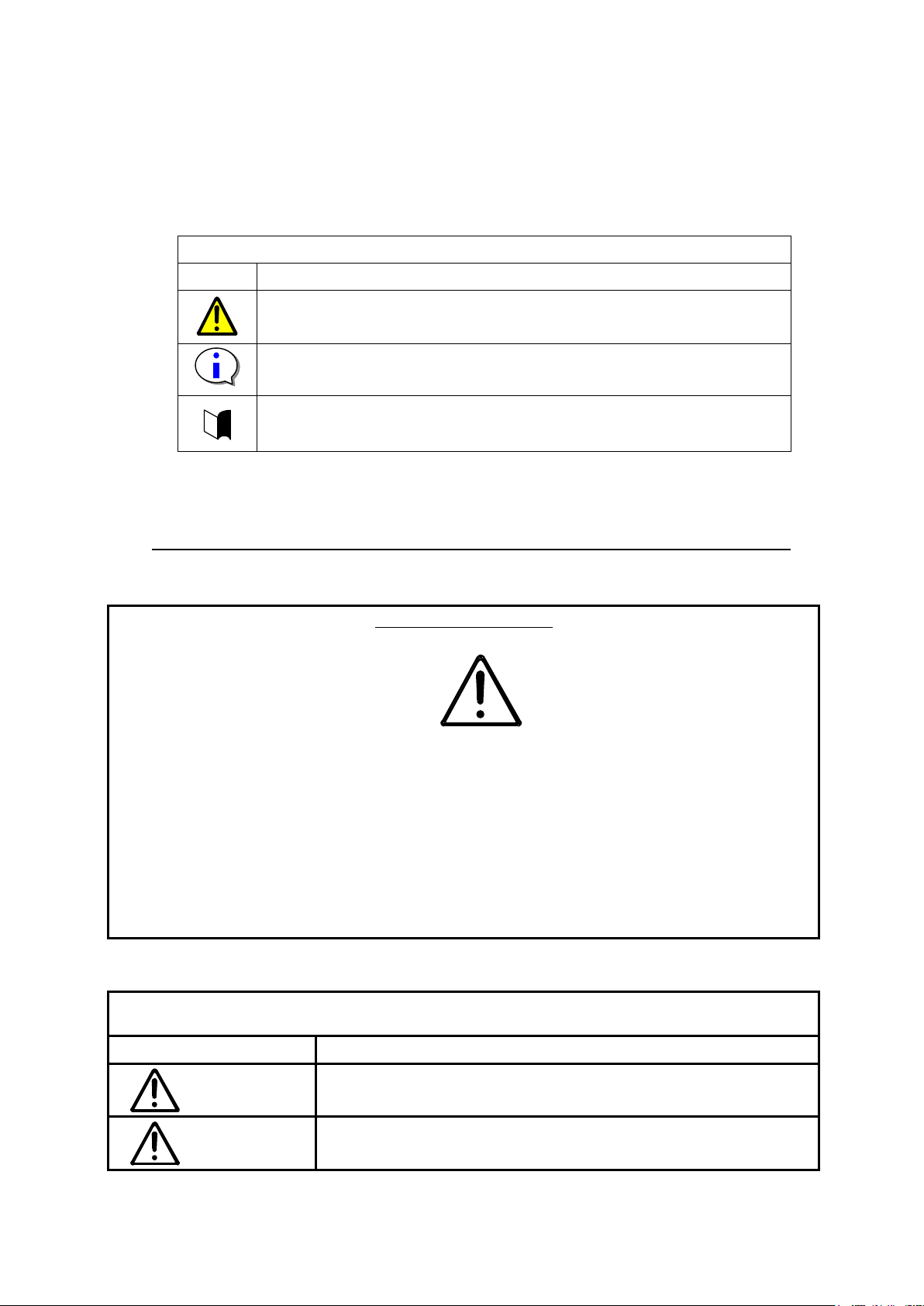
Notation Used in this Document
The following symbols are used in this document.
Display Types
Type Description
Indicates that failure to follow directions could result in damage to
equipment or data.
Provides clarifying information or specific instructions
Safety Guidelines
To ensure safety, read and understand these "Safety Guidelines" before using this product.
Development Association (JEIDA).
Since it indicates guidelines of particular impor
accompanying text before use.
Always obey the precautions indicated by this symbol.
If you ignore these instructions when handling the product, the danger indicated by the w
icon may occur.
Warning icons are classified into two levels represented by the accompanying word.
Provides additional information.
Explanation of Symbol
Warning Display Types
Type Description
Warning
Caution
Indicates that there is a risk of death, serious injury, or burns.
Indicates that there is a risk of injury and/or loss of assets.
- 3-
Page 5
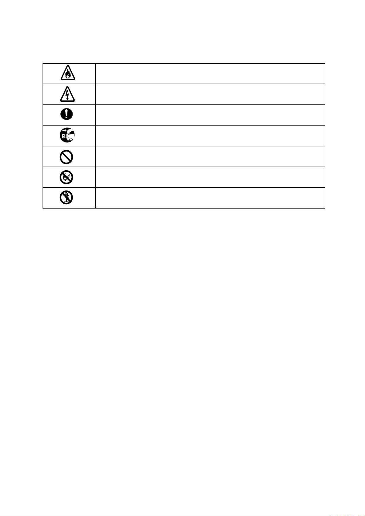
Indicates that you may be electrically shocked.
Indicates that smoking and/or ignition may occur.
Indicates proper procedure for safety.
Indicates that the plugs of power cords should be removed for safety.
Indicates general prohibitions.
Indicates that fire should not be brought near devices for safety.
Indicates that devices are prohibited from being disassembled for safety.
- 4-
Page 6
Caution
2 Installation Environment
This section describes precautions that should be kept in mind when installing the disk array unit and installation
conditions.
Use the disk array unit in an environment with an ambient temperature range of 5 C to 40 C (recommended
range).
In particular, for 24-hour operation, make sure that air conditioning schedules (nights or holidays) are appropriate
to keep the disk array unit within the specified temperature range.
If this temperature condition is not satisfied, it may cause electronic components to malfunction or breakdown, or
may shorten their replacement intervals.
・ For 24-hour operation particularly during summertime, make sure that air conditioning is also provided in the
nights and on holidays as needed so that the temperature range does not exceed 40 C.
・ Regulate the heating during wintertime to prevent the temperature from rising more than 15 C per hour so
that condensation does not occur.
Be sure to satisfy the following installation conditions when operating the disk array unit. If the disk array unit is
operated in an environment that does not satisfy these conditions, it may cause the unit to breakdown or may
significantly shorten its replacement period.
・ Temperature (5 C to 40 C: recommended range)
Do not install the disk array unit where it would be exposed to direct sunlight or subjected to severe
temperature conditions. Also, since sudden temperature changes will negatively affect the parts of the disk
array unit and may cause them to breakdown, the ideal increase in temperature should not exceed 10 C per
hour. Avoid an environment in which the temperature increases more than 15 C per hour.
・ Humidity (10% to 80% RH: recommended range)
If the disk array unit is installed in a high-humidity environment, interactions with corrosive toxic substances
and dust may cause it to breakdown. Since high humidity also negatively affects magnetic media, use air
conditioning to regulate the humidity.
- 5-
Page 7
Main components such as controller, cache, power supply,
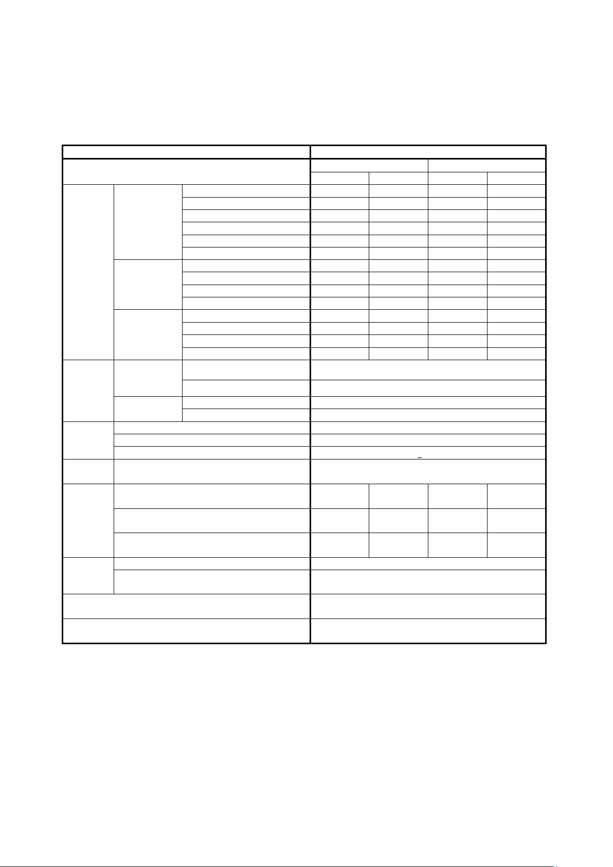
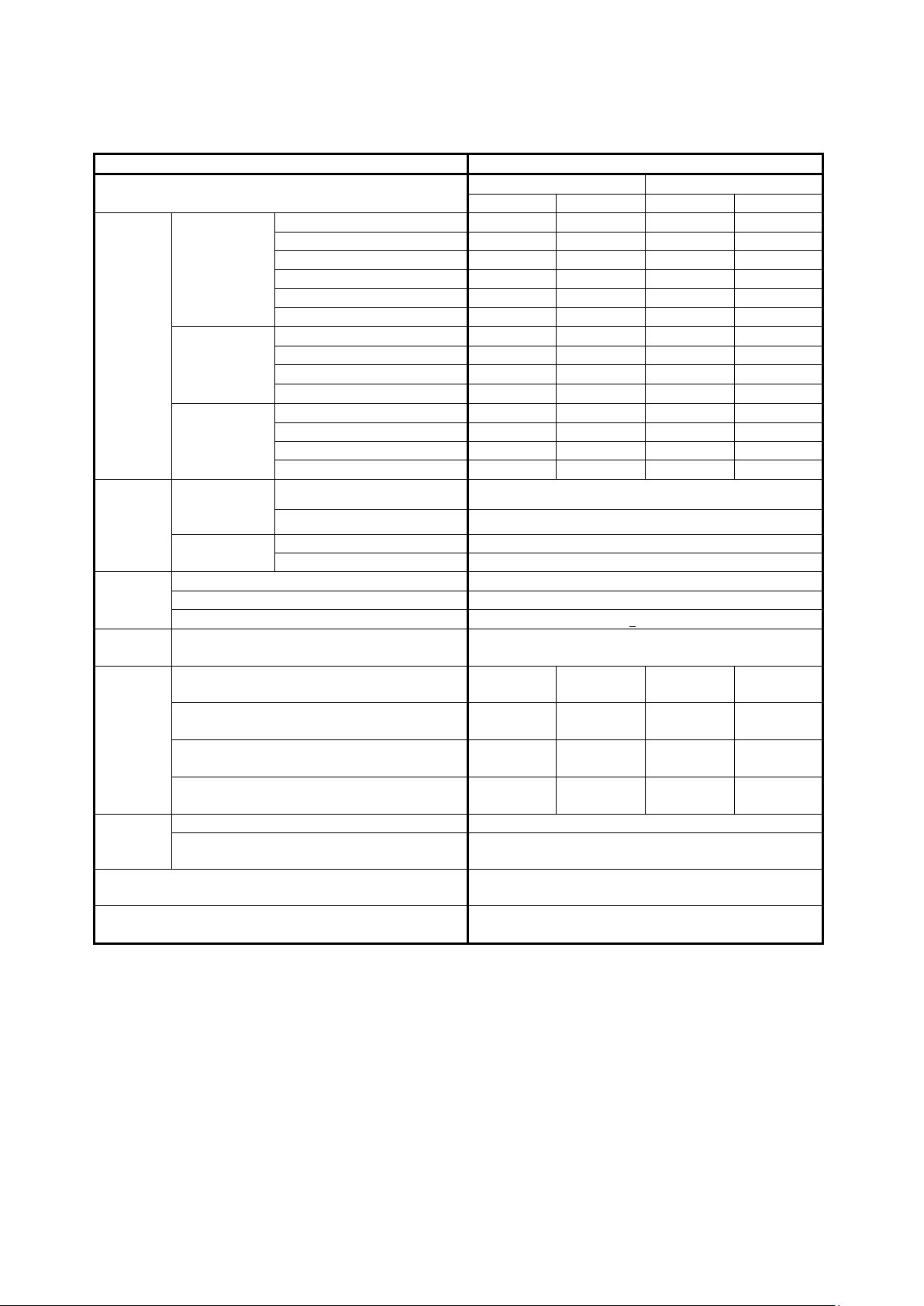
3 Installation Specifications
The following table shows the installation specifications.
Table 3.1 NEC Storage M100 Product Specifications
Product Name NEC Storage M100 Disk Array Unit
Configuration
300GB disk drive 282GB 24.3TB 282GB 24.3TB
450GB disk drive 435GB 37.3TB 435GB 37.3TB
SAS HDD
configuration
Storage
capacity
*1 *2
Chassis
dimensions
(W×D×H)
Weight
Power
Supply
Power
consumption
Inrush
current
(peak)
Temperature / Humidity conditions
NL-SAS HDD
configuration
SAS SSD
configuration
Disk array
controller
(U count)
Disk enclosure
(U count)
Disk array controller < 31kg
Disk enclosure < 29kg
Accessories (Rails for rack mount, cables) < 3kg
100V to 240V AC, single phase 50/60Hz *3
SAS HDD configuration
(3.5”15Krpm)
SAS HDD configuration
(2.5”10Krpm)
NL-SAS HDD configuration
(2.5”/3.5”7.2Krpm)
Main chassis 25Ao-p/AC line
Disk enclosure 25Ao-p/AC line
600GB disk drive 571GB 48.9TB 571GB 48.9TB
600GB encrypted disk drive 571GB 48.9TB 571GB 48.9TB
900GB disk drive 874GB 74.7TB - -
1.2TB disk drive 1.16TB 99.6TB - 1TB disk drive 979GB 83.7TB 979GB 83.7TB
2TB disk drive - - 1.9TB 166.8TB
3TB disk drive - - 2.9TB 249.0TB
4TB disk drive - - 3.9TB 333.4TB
100GB drive 89GB 897GB 89GB 897GB
200GB drive 187GB 1.4TB 187GB 1.4TB
400GB drive 387GB 3.7TB 387GB 3.7TB
800GB drive 757GB 5.9TB 757GB 5.9TB
without Front Bezel 482×513.2×87.8mm(2U)
with Front Bezel 482×545.2×87.8mm(2U)
without Front Bezel 482×513.2×87.8mm(2U)
with Front Bezel 482×545.2×87.8mm(2U)
2.5”(24HDD model) 3.5”(12HDD model)
min max min max
- - 485W 2690W
485W 1415W - -
450W 1275W 435W 2290W
During operation : +5C to +40C / 10% to 80%
During storage : -10C to +60C / 5% to 80%
Redundancy
Numbers in the table are calculated based on 1 GB = 1,000,000,000 bytes and 1TB = 1,000,000,000,000 bytes.
and fan are duplicated
- 6-
Page 8
upply,
Table 3.2 NEC Storage M300 Product Specifications
Product Name NEC Storage M300 Disk Array Unit
Configuration
300GB disk drive 282GB 36.4TB 282GB 24.3TB
450GB disk drive 435GB 56.0TB 435GB 37.3TB
SAS HDD
configuration
Storage
capacity
*1 *2
Chassis
dimensions
(W×D×H)
Weight
Power
Supply
Power
consumption
Inrush
current
(peak)
Temperature / Humidity conditions
Redundancy
NL-SAS HDD
configuration
SAS SSD
configuration
Disk array
controller
(U count)
Disk enclosure
(U count)
Disk array controller < 31kg
Disk enclosure < 29kg
Accessories (Rails for rack mount, cables) < 3kg
100V to 240V AC, single phase 50/60Hz *3
SAS HDD configuration
(3.5”15Krpm)
SAS HDD configuration
(2.5”15Krpm)
SAS HDD configuration
(2.5”10Krpm)
NL-SAS HDD configuration
(2.5”/3.5”7.2Krpm)
Main chassis 25Ao-p/AC line
Disk enclosure 25Ao-p/AC line
600GB disk drive 571GB 73.4TB 571GB 48.9TB
600GB encrypted disk drive 571GB 73.4TB 571GB 48.9TB
900GB disk drive 874GB 112.1TB - -
1.2TB disk drive 1.16TB 149.4TB - 1TB disk drive 979GB 125.7TB 979GB 83.7TB
2TB disk drive - - 1.9TB 166.8TB
3TB disk drive - - 2.9TB 249.0TB
4TB disk drive - - 3.9TB 333.4TB
100GB drive 89GB 897GB 89GB 897GB
200GB drive 187GB 1.4TB 187GB 1.4TB
400GB drive 387GB 3.7TB 387GB 3.7TB
800GB drive 757GB 5.9TB 757GB 5.9TB
without Front Bezel 482×513.2×87.8mm(2U)
with Front Bezel 482×545.2×87.8mm(2U)
without Front Bezel 482×513.2×87.8mm(2U)
with Front Bezel 482×545.2×87.8mm(2U)
2.5”(24HDD model) 3.5”(12HDD model)
min max min max
- - 510W 2715W
505W 2055W - -
505W 2055W - -
470W 1845W 455W 2310W
During operation : +5C to +40C / 10% to 80%
During storage : -10C to +60C / 5% to 80%
Main components such as controller, cache, power s
and fan are duplicated
Numbers in the table are calculated based on 1 GB = 1,000,000,000 bytes and 1TB = 1,000,000,000,000 bytes.
- 7-
Page 9

ypted disk
Accessories (Rails for rack mount,
Main components such as controller, cache, power supply, and fan are
Table 3.3 NEC Storage M500 Product Specifications
Product Name NEC Storage M500 Disk Array Unit
Configuration 2.5”(24HDD model) 3.5”(12HDD model)
min max min max
300GB disk drive 282GB 97.3TB 282GB 97.3TB
450GB disk drive 435GB 149.3TB 435GB 149.3TB
SAS HDD
configuration
Storage
capacity
*1 *2
Chassis
dimensions
(W×D×H)
Weight
Power
Supply
Power
consumption
Inrush
current
(peak)
Temperature / Humidity conditions
NL-SAS HDD
configuration
SAS SSD
configuration
Disk array
controller
(U count)
Disk enclosure
(U count)
Disk array controller < 39kg
Disk enclosure < 29kg
cables)
100V to 240V AC, single phase 50/60Hz *3
8Gb FC 440W
1G iSCSI 435W
10G iSCSI 455W
Mixed model
Disk
enclosure
Main chassis AC:25Ao-p/AC line、DC:20 Ao-p
Disk enclosure AC:25Ao-p/AC line、DC:20 Ao-p
600GB disk drive 571GB 195.7TB 571GB 195.7TB
600GB encr
drive
900GB disk drive 874GB 299.1TB - -
1.2TB disk drive 1.16TB 398.6TB - 1TB disk drive 979GB 335.0TB 979GB 335.0TB
2TB disk drive - - 1.9TB 667.2TB
3TB disk drive - - 2.9TB 996.3TB
4TB disk drive - - 3.9TB 1333.9TB
100GB drive 89GB 897GB 89GB 897GB
200GB drive 187GB 1.4TB 187GB 1.4TB
400GB drive 387GB 3.7TB 387GB 3.7TB
800GB drive 757GB 5.9TB 757GB 5.9TB
without Front Bezel
with Front Bezel 480×639×175.4mm(4U)
without Front Bezel
with Front Bezel 482×545.2×87.8mm(2U)
SAS HDD (3.5”15krpm) - 315W
SAS HDD (2.5”10krpm) 315W NL-SAS HDD
(2.5”/3.5”7.2krpm)
571GB 195.7TB 571GB 195.7TB
480×602.5×175.4mm(4U)
482×513.2×87.8mm(2U)
< 3kg
FCx8 Port+1Gb iSCSIx4 Port:435W
FCx8 Port+10Gb iSCSIx4 Port:445W
275W 265W
During operation : +5C to +40C / 10% to 80%
During storage : -10C to +60C / 5% to 80%
Redundancy
Numbers in the table are calculated based on 1 GB = 1,000,000,000 bytes and 1TB = 1,000,000,000,000 bytes.
duplicated
- 8-
Page 10

encrypted disk
Accessories (Rails for rack mount,
Main components such as controller, cache, power supply, and fan are
Table 3.4 NEC Storage M700 Product Specifications
Product Name NEC Storage M700 Disk Array Unit
Configuration 2.5”(24HDD model) 3.5”(12HDD model)
min max min max
300GB disk drive 282GB 243.3TB 282GB 243.3TB
600GB disk drive 571GB 489.4TB 571GB 489.4TB
SAS HDD
configuration
Storage
capacity
*1 *2
Chassis
dimensions
(W×D×H)
Weight
Power
Supply
Power
consumption
Inrush
current
(peak)
Temperature / Humidity conditions
NL-SAS HDD
configuration
SAS SSD
configuration
Disk array
controller
(U count)
Disk enclosure
(U count)
Disk array controller < 48kg
Disk enclosure < 29kg
cables)
100V to 240V AC, single phase 50/60Hz *3
8Gb FC 1100W
1G iSCSI 1090W
10G iSCSI 1130W
Disk
enclosure
Main chassis AC:25Ao-p/AC line
Disk enclosure AC:25Ao-p/AC line
600GB
drive
900GB disk drive 874GB 747.9TB - -
1.2TB disk drive 1.16TB 996.5TB - 2TB disk drive - - 1.9TB 1668.1TB
3TB disk drive - - 2.9TB 2490.9TB
4TB disk drive - - 3.9TB 3334.9TB
100GB drive 89GB 897GB 89GB 897GB
200GB drive 187GB 1.4TB 187GB 1.4TB
400GB drive 387GB 3.7TB 387GB 3.7TB
800GB drive 757GB 5.9TB 757GB 5.9TB
without Front Bezel
with Front Bezel 480×639×175.4mm(4U)
without Front Bezel
with Front Bezel 482×545.2×87.8mm(2U)
SAS HDD (3.5”15krpm) - 315W
SAS HDD (2.5”10krpm) 310W NL-SAS HDD
(3.5”7.2krpm)
571GB 489.4TB 571GB 489.4TB
480×602.5×175.4mm(4U)
482×513.2×87.8mm(2U)
< 3kg
- 265W
During operation : +5C to +40C / 10% to 80%
During storage : -10C to +60C / 5% to 80%
Redundancy
Numbers in the table are calculated based on 1 GB = 1,000,000,000 bytes and 1TB = 1,000,000,000,000 bytes.
duplicated
- 9-
Page 11

*1: Minimum capacity when using SAS/NL-SAS disk drive: RAID-TM.
When using SSD: RAID-1 x 2.
However, at least three disk drives must be installed at the beginning of the main chassis in the disk array
unit.
*2: Maximum capacity when using SAS/NL-SAS disk drive: RAID-5 (8+P).
When using SSD: RAID-5 (4+P).
*3: AC input power inlet corresponds to IEC320 C-14.
- 10-
Page 12

4 Installation Area
Figure 4.1 shows the required installation area.
・ Be sure to provide a work area as shown below in order to connect cables and perform necessary
maintenance of installed equipment.
- At least 1.0 m in the front and rear of the rack
- At least 0.6 m to the left and right of the rack (when racks are coupled, to the left and right of the coupled
unit)
- At least 0.4 m from the top of the rack to the ceiling
≥ 0.6 m
≥ 1.0 m
≥ 0.4 m from
top of rack to
≥ 0.6 m
ceiling
≥ 1.0 m
Figure 4.1 Installation Area
- 11-
Page 13

Service Area
Figure 4.2 shows the required service area.
・ A service area of at least 1.0 m is required in the front and rear of the disk array unit.
≥ 1.0 m
≥ 1.0 m
(Service area)
Rack
(top view)
Front
(Service area)
Figure 4.2 Service Area
- 12-
Page 14

5 Installation of the Disk Array Unit
5.1 Check the Floor Load
・ Verify that no floor loading problem will occur when the disk array unit is installed in the rack.
- Although the floor load is approximately 300kg/m2 in an ordinary office and approximately 500 kg/m2 in a
computer room, check the floor strength of the actual installation location and reinforce it if necessary.
- Check the load carrying capacity of the floor taking into consideration the disk array units installed in the
rack. Also, the weight that can be installed differs according to the rack that is used. Discuss this with the
operations or maintenance personnel in charge.
・ Sample calculation of the weight on the floor where the rack is located
Assumed conditions --- M100 1DAC+7DE case
Rack weight: 170 kg
Total weight of disk array units: (31kg+3kg) + (29kg+3kg) x 7 = 258kg
Installation area when a standalone rack is installed: 5.4 m2
Total weight Installation area Unit load
(Rack weight + Weight of installed units) (Including work area)
(170 kg + 258kg) ÷ 5.4 m2 = 79.26 kg/m
Therefore, since this is less than 300 kg/m2, this configuration can be installed even in an ordinary office.
2
- 13-
Page 15

Installation area
・ Area for standalone installation: 5.4 m2
・ Area for coupled installation: 1.2 m2
Front
Front
Front
(Rack)
(Rack)
(Rack)
Figure 5.1.1 Standalone Installation
Rear
Rear
0.6m
Rear
Figure 5.1.2 Coupled Installation
Rack
1.0 m
1.0 m 0.5 m 0.5 m
Rear
Rear
0.6 m
0.6 m
0.6 m
(Rack)
(Rack)
1.0 m 1.0 m
Front
(Rack)
Front
Front
Front
(Rack)
Front
(Rack)
Rear
Rear
Rear
- 14-
Page 16

5.2 Means of Preventing Rack from Tipping Over
・ Fasten the rack to the floor.
Use an appropriate method of fastening the rack to the floor so that mounting disk array units in the rack
does not cause the entire rack to become unstable.
- Be careful not to injure yourself when mounting disk array units in the rack.
- Do not mount disk array units in a rack that would become physically unstable.
- The weight of the disk array controller for the maximum configuration M100/M300 (Disk array controller +
Accessory) is approximately 34 kg, M500 (Disk array controller + Accessory) is approximately 42 kg, and
M700 (Disk array controller + Accessory) is approximately 51 kg.
・ If an appropriate method cannot be found to fasten the rack to the floor, attach a stabilizer.
Someone might be injured if vibration caused the rack to tip over.
5.3 Rack Mounting Rules
・ To prevent the entire rack from becoming unstable when disk array units are mounted in the rack, mount
heavier units at the bottom and lighter units at the top.
・ If a rack in which disk array units are mounted has an empty area where no units are installed, attach a
closing plate (blank panel) to prevent a breeze from circulating within the rack.
- There is a risk that air circulating in the rack may prevent the ambient environmental conditions of the
disk array unit specifications from being satisfied.
- 15-
Page 17

5.4 Air Flow
・ When mounting disk array units in the rack, take the installation specifications into consideration so that
ambient environmental conditions can be satisfied while operating the disk array units.
・ When installing units in a rack with a door or a rack equipped with multiple units, take the following points
into consideration when the units are operating.
- Take air flow into consideration so that the temperature requirement of the ambient environmental
conditions is not exceeded.
- Make every effort to prevent the temperature inside a rack in which disk array units are operating from
exceeding 40 C.
・ A constant volume of air is required for the disk array units to operate safely.
When mounting units in the rack, make sure that no object blocks the air vents at the front and rear of the
disk array unit and that the air vents are not closed.
・ Note the following points so that rack mounted equipment has a front intake and rear exhaust.
- Take measures regarding wind direction such as installing air conditioning so that cool air flows onto the
front of the rack.
- For under-floor air conditioning, since there are no intake vents in the rack floor, install louvered vents in the
floor in front of the equipment so that a greater volume of cool air flows in than the exhaust from the
installed equipment.
- When installing multiple racks, take into consideration the intake air of the racks and install them so that the
fronts are facing each other and the backs are facing away from each other.
- Take measures such as installing an exhaust duct above the rear of the rack so that the exhaust does not
flow around to the front of the rack or stay confined at the rear of the rack.
- 16-
Page 18

Front
Front
Front
Rear
Front
Rear
Front
Rear
Front
Rear
Rear
Rear
Air conditioning
Figure 5.4 Air Flow (When Multiple Racks are installed)
- 17-
Page 19

Warning
5.5 Uninterruptible Power Supply (UPS)
(1) Selection of UPS
・ Use of a UPS is recommended to minimize power outages or momentary voltage drops (flickers) of
commercial power due to lightning strikes.
・ Select a power supply such as a line interactive UPS so that the momentary voltage drop that occurs when
switching to battery operation does not fall below the flicker tolerance(10ms) of the disk array unit.
・ Installing a UPS for each redundant power supply of the disk array unit is recommended to limit the effect of
a UPS equipment failure.
・ If one unit of a redundant power supply fails, the total power load is supplied from the other power supply.
Therefore, the total power load must be able to be supplied even if the UPS electric power selection is
supplied to one unit of a redundant power supply.
・ Select a UPS that satisfies the requirements for both the total apparent power (VA) and the total effective
power (W) of the disk array unit.
・ Since the starting current (inrush current) of the disk array unit flows to the UPS, select a UPS that permits
this current.
・ The disk array unit is equipped with switching power supplies and an X/Y capacitor to counter EMI at its input.
When numerous devices are connected to the UPS, the leading phase current due to the capacitor increases.
Since a large oscillating current may occur in some UPS devices due to this leading phase current causing the
circuit breaker between the UPS and disk array unit to burnout, check with the UPS manufacturer to make
sure that this will not be a problem. Note that this has been verified for UPS devices manufactured by NEC
and NEC Fielding.
(2) Setup
・ For a UPS that allows the power fault detection sensitivity to be switched and the permissible voltage to be
set, use manual switches and automatic running software such as EMSPRO/AC Enterprise to set the
recommended sensitivity (high sensitivity) and recommended voltage according to the UPS and automatic
running software user's guides.
・ If a UPS is installed for each redundant power supply of the disk array unit, set each UPS so that both
devices will be on almost simultaneously (within one minute). If the times in which the two UPS devices
are on differ significantly, a power fault may be detected in the disk array unit.
- 18-
Page 20

6 Precautions
6.1 Precautions When Mounting Disk Array Units in an Unauthorized Rack
This section presents safety precautions when installing disk array units in an unauthorized rack.
These precautions are presented to ensure safety when disk array units are installed in an unauthorized rack.
However, proper operation of the disk array units cannot be guaranteed if they are installed in an unauthorized
rack. For information about authorized racks, contact your sales representative.
6.2 Directions for Safe Mounting
・ When mounting disk array units in a rack, take the installation specifications into consideration so that
ambient environmental conditions can be satisfied while the disk array units are operating.
When installing units in a rack with a door or a rack equipped with multiple units, take the following points
into consideration when the units are operating.
- Take air flow into consideration so that the temperature requirement of the ambient environmental
conditions is not exceeded.
- The temperature inside a rack in which disk array units are operating must not exceed 40 C.
・ A constant volume of air is required for the disk array unit to operate safely.
・ When mounting units in the rack, make sure that no object blocks the air vents at the front and rear of the
disk array unit and that the air vents are not closed.
・ Fasten the rack to the floor.
Use an appropriate method of fastening the rack to the floor so that mounting disk array units in the rack
does not cause the entire rack to become unstable.
- Be careful not to injure yourself when mounting disk array units in the rack.
- Do not mount disk array units in a rack that would become physically unstable.
- For the maximum configuration of disk array units, the weight of the M100/M300 disk array controller is
approximately 31 kg, weighty of the M500 disk array controller is approximately 39 kg, weighty of the
M700 disk array controller is approximately 48 kg , and the weight of the disk enclosure is approximately
29kg.
・ Connecting the power cord of a disk array unit to a power strip or the service outlet of another unit may
subject the connected power strip or power cord of the other unit to a high load.
Verify that the total current rating of units including the disk array unit does not exceed the current rating of
the connected power strip or service outlet of the other unit.
・ Always ground a unit that is mounted in a rack.
Be particularly careful if the power cord of the disk array unit is not directly connected to a power distribution
board (such as when using a power strip).
- 19-
Page 21

Warning
Warning
Always ground the disk array unit before connecting the power cord.
Connecting all the power cords of disk array units to a single power distribution board will result in a large leak
current flowing in the ground wires of the power cords, which may cause an electric shock. Always connect each
power cord to a separate power distribution board.
If the power cord of the disk array unit is not directly connected to a power distribution board, use a power strip
with an industrial plug.
6.3 Precautions When Installing or Moving a Disk Array Unit
Note the following precautions when installing or moving a disk array unit.
・ Do not place the disk array unit in a location that is high in humidity, dust, or oily smoke, a poorly ventilated
location, or any location with fire. This will cause the disk array unit to fail, catch fire, or cause an electric
shock.
・ Do not use any other power cord than the one supplied with the disk array unit. Using another power cord
may cause a fire to occur.
・ Do not use the disk array unit with a voltage other than the one shown on the nameplate. Also, do not
overload the electrical circuit. Failure to follow these prohibitions may cause a fire or electric shock to occur.
・ Do not insert or remove the power plug with wet hands. Failure to follow this prohibition may cause an
electric shock to occur.
・ Always ground a unit that requires grounding before turning it on.
Warning
If grounding is not possible, contact your sales representative or maintenance personnel. If there is a short
circuit, a fire or electric shock may occur.
Prohibited
- 20-
Page 22

Caution
Prohibited
Caution
・ When removing the power plug from the electrical outlet, always grasp the plug. Do not pull the power cord.
Pulling the power cord may expose or disconnect the core wires and cause a fire or electric shock to occur.
・ Do not place any object on the disk array unit. Also, do not drop any object onto the disk array unit or crash
any object into it.
Failure to follow these prohibitions may cause the disk array unit to become unbalanced and tip over or fall.
It may also cause the disk array unit to fail or malfunction.
・ Select an installation location for the disk array unit that satisfies the product specifications as well as the
following conditions. Otherwise, the unit may be damaged, data may be lost, or the life of the unit may be
shortened.
- Do not place the disk array unit in a location that is high in humidity, dust, or oily smoke, a poorly ventilated
location, or any location with fire.
- Do not use the disk array unit in an area subject to salt-air damage.
- Do not use the disk array unit in a bathroom, shower room, or any other room where water is used.
- Install the disk array unit in a location that is not exposed to direct sunlight.
- Install the disk array unit in a location with little dust and low humidity.
- Install the disk array unit in a flat, stable location where severe vibrations do not occur. A location subject to
severe vibrations or an unstable location such as an inclined surface may cause the unit to fall or tip over.
- Do not install the disk array unit near a passageway. If it is installed near a passageway, the disk array unit
may fail or malfunction due to vibrations caused by people walking by.
- Do not install the disk array unit in a location where power cords or various types of cables are found.
- Do not block the air vents of the disk array unit. Air is taken in from the front of the unit and is exhausted
from the rear. Do not seal off the front or rear of the disk array unit with a cover or lean any objects against
them.
- Do not install the disk array unit near any device that generates electrical noise including any device using
a motor such as an ungrounded air conditioner or washing machine.
- Do not install the disk array unit in the vicinity of a device that generates a strong magnetic field (such as a
motor or speaker).
・ Insert the power plug snugly all the way into the power outlet. Failure to do this may cause a fire to occur or
the unit to fail.
Instruction
- 21-
Page 23

Caution
Instruction
・ Use an appropriate method to fasten the rack to the floor. If an appropriate method cannot be found, attach
a stabilizer. Someone might be injured if vibration caused the rack to tip over.
・ Connecting a UPS is recommended to prevent data loss due to a power failure.
If a power failure occurs, operation of the disk drive may become unstable.
・ Before attaching a fiber channel cable to the connector, verify that no dust, dirt, or oil is adhering to the
connector.
・ A fiber channel cable is thin and easily damaged. Do not excessively bend it or force it into the device.
・ Moving the disk array unit through an extremely uneven area may subject the device to shocks or vibrations
and cause data loss.
Also, pay careful attention to steps or gaps in the floor surface (such as the gap at the entrance of an
elevator).
・ At least two people should carry a disk array unit on a slope since the weight will increase on one side.
・ When moving the rack up or down a slope, make sure the front and back of the disk array unit face the
direction of travel. If the side of the disk array unit faces the direction of travel, the unit may be damaged.
――――― End ―――――
- 22-
Page 24

NEC Storage M100/M300/M500/M700
Disk Array Unit
Installation Guide
Tenth edition
Nov 2013
NEC Corporation
5-7-1 Shiba Minato-ku, Tokyo Japan
81-3-3454-1111
© NEC Corporation 2011-2013
No part of the content of this manual may be produced or transmitted in
any form or by any means without the written permission of the NEC
Corporation.
Information in this manual is subject to change without notice.
- 23-
 Loading...