

Visual Systems Division
Technical Bulletin
LT85 Throw Distance Data
Desktop and Ceiling Mount Rev. 1.6
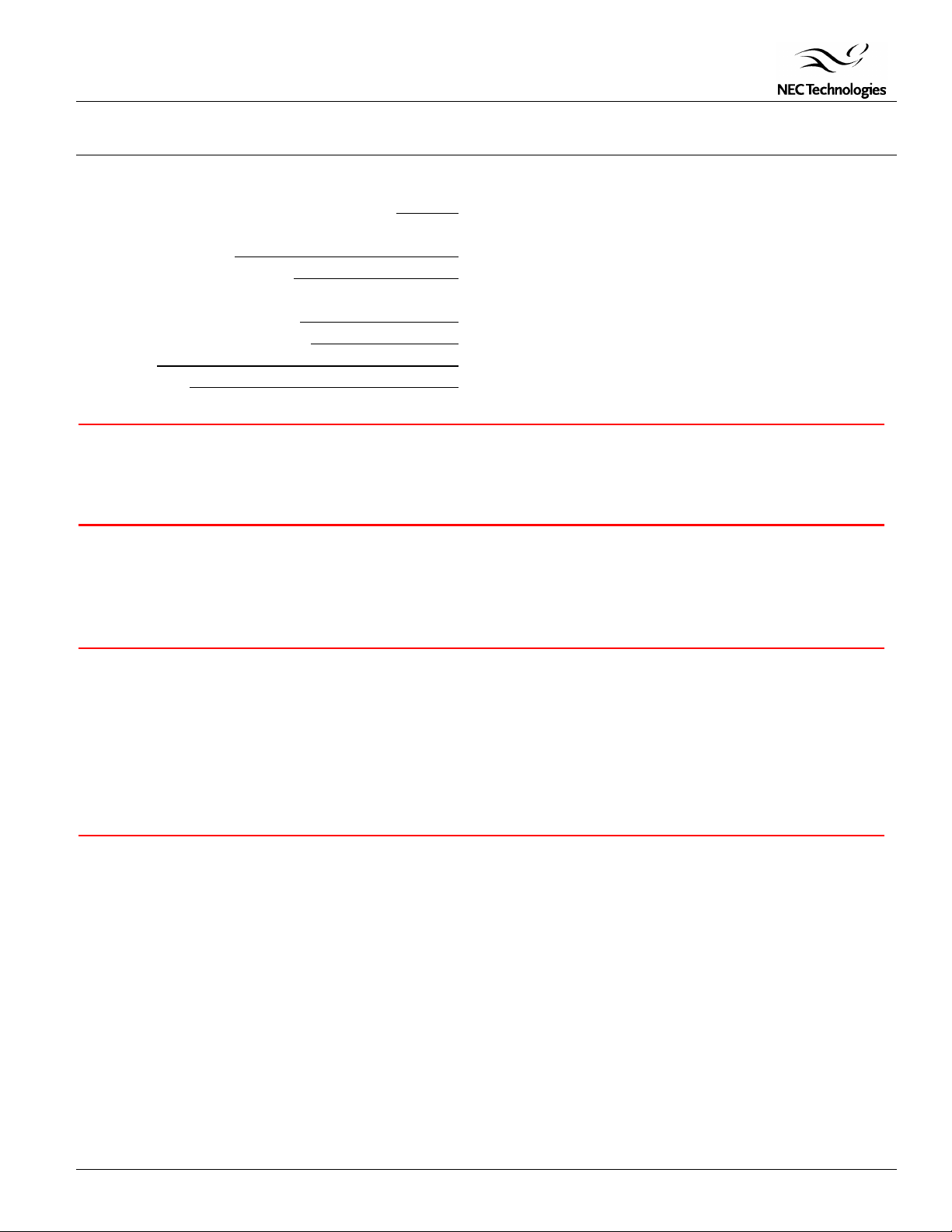
Contents
Product Description, Lens Specs, Notes & Formulas Page 1
Projection Distances and Screen Sizes
Desktop Setup Page 2
Ceiling Mount Installation Page 3
Cabinet Dimensions
Top, Front and Right Side Page 4
Bottom, Back and Left Side Page 5
Timing Chart Page 6
PC Control Codes Page 7
Product Description
Type: Single chip DLP
Native Resolution: 800 x 600 Weight: 3.3 lbs
Brightness: 800 ANSI Lumens
Lens Specifications
Manual Focus (No Zoom) F3.0 f = 20.3mm
Screen Sizes: 36" - 200" diagonal
Throw Ratio: 1.64 - 1.69:1 (dependent on screen size and focus setting)
Offset Angle: 17.0° – 17.2°
Notes
§ For Screen Sizes of 36 to 200 inches not indicated on the projection tables, use the formulas below.
§ If the figures on the tables do not match the figures in the formulas, use the figures in the table.
§ The ceiling must be strong enough to support the LCD projector and the installation must be in accordance with any local
building codes.
• All calculations are based on screen with. (regardless of aspect ratio)
• Distances are in inches, for millimeters multiply by 25.4.
• Distances may vary ±5%.
Formulas
Units: Inches (for millimeters multiply final number by 25.4)
D = Screen Diagonal (4:3)
H = D x 0.8 H = Screen Width (4:3)
V = D x 0.6 V = Screen Height (4:3)
B = 0.5222H B = Vertical distance between lens center and screen center
C = 1.696H – 0.1344 C = Throw distance
D = 0.1472H D = Vertical distance between lens center and top of screen (bottom of screen for
desktop application)
-1
α = tan
(B / C) α = Throw angle
Page 1
projector Dimensions: 9.4”(W) x 2.1”(H) x 7.7”(D) (not incl. Protrusions)
Visual Systems Division
Technical Bulletin
LT85 Throw Distance Data
Desktop and Ceiling Mount Rev. 1.6
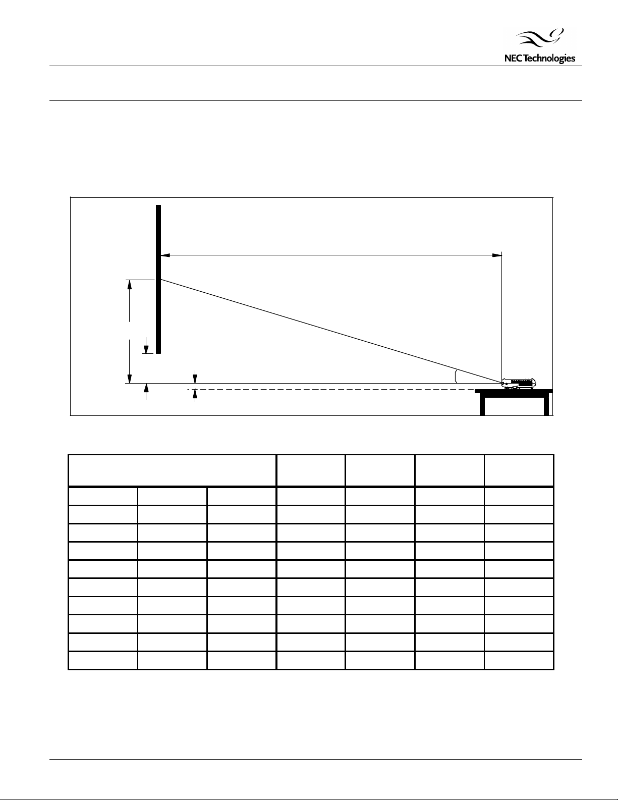
Projection Distance and Screen Size for Desktop
The following shows the proper relative positions of the projector and screen. Refer to the table to determine the position of
installation.
Distances are in inches. For millimeters multiply by 25.4.
Desktop Setup
C
Throw Distance
Screen Ctr
B
Lens Ctr
Distance Chart
Diagonal Width (H) Height (E)
40" 32" 24" 16.7" 54.7" 4.7" 17.0°
60" 48" 36" 25.1" 81.9" 7.1" 17.0°
67" 53.6" 40.2" 28.0" 90.8" 7.9" 17.1°
72" 57.6" 43.2" 30.1" 97.6" 8.5" 17.1°
84" 67.2" 50.4" 35.1" 113.8" 9.9" 17.1°
90" 72" 54" 37.6" 122.0" 10.6" 17.1°
100" 80" 60" 41.8" 135.8" 11.8" 17.1°
120" 96" 72" 50.2" 162.6" 14.2" 17.1°
150" 120" 90" 62.8" 203.5" 17.8" 17.1°
Screen Bottom
D
1.5"
Screen Size B C D
α
α
180" 144" 108" 75.3" 244.1" 21.3" 17.1°
Note:
For screen sizes of 36 to 200 inches not indicated on the projection tables, use the formulas on page 1.
Page 2
Visual Systems Division
Technical Bulletin
LT85 Throw Distance Data
Desktop and Ceiling Mount Rev. 1.6
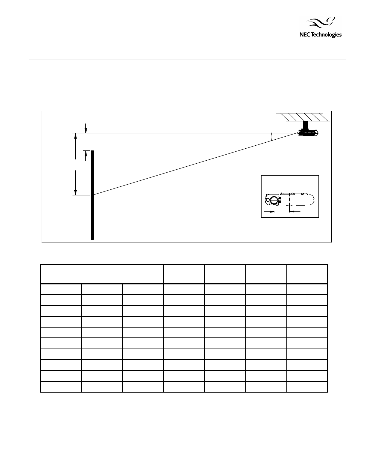
Projection Distance and Screen Size for Ceiling Mount Installation
The following diagram shows the relationship between projector position and the screen.
Distances are in inches. For millimeters multiply by 25.4.
Ceiling Mount Installation
Lens Ctr
Screen Ctr
Distance Chart
Diagonal Width (H) Height (E)
40" 32" 24" 16.7" 54.7" 4.7" 17.0°
60" 48" 36" 25.1" 81.9" 7.1" 17.0°
C
Throw Distance
D
Screen Top
B
Screen Size B C D
α
Lens Offset from
Ctr of Projector
2.96
LT
150
α
67" 53.6" 40.2" 28.0" 90.8" 7.9" 17.1°
72" 57.6" 43.2" 30.1" 97.6" 8.5" 17.1°
84" 67.2" 50.4" 35.1" 113.8" 9.9" 17.1°
90" 72" 54" 37.6" 122.0" 10.6" 17.1°
100" 80" 60" 41.8" 135.8" 11.8" 17.1°
120" 96" 72" 50.2" 162.6" 14.2" 17.1°
150" 120" 90" 62.8" 203.5" 17.8" 17.1°
180" 144" 108" 75.3" 244.1" 21.3" 17.1°
Note:
For screen sizes of 36 to 200 inches not indicated on the projection tables, use the formulas on page 1.
Page 3

Visual Systems Division
Technical Bulletin
LT85 Throw Distance Data
Desktop and Ceiling Mount Rev. 1.6
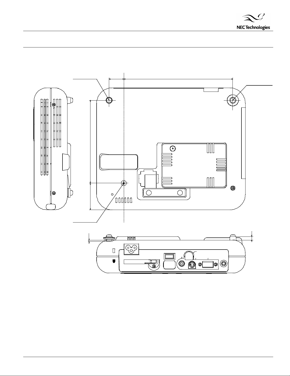
Cabinet Dimensions
The following diagrams show the cabinet dimensions for the MultiSync LT85/150.
Dimensions are in inches. For millimeters multiply by 25.4.
CANCEL
SELECT
MENU
ENTER
ADJUST
AUTO
PC CARD ACCESS
9.37
SOURCE
STAND BY
ON/
POWER
STATUS
7.72
1.71
TM
‚c‚k‚o
‚`•@‚s‚d‚w‚`‚r•@‚h‚m‚r‚s‚q‚t‚l‚d‚m‚s‚r•@‚s‚d‚b‚g‚m‚n‚k‚n‚f‚x
2.09
1.16
0.335
Page 4
Visual Systems Division
Technical Bulletin
LT85 Throw Distance Data
Desktop and Ceiling Mount Rev. 1.6
Cabinet Dimensions (continued)
The following diagrams show the cabinet dimensions for the MultiSync LT85/150.
Dimensions are in inches. For millimeters multiply by 25.4.
M4 (DEPTH 4mm)
5.24
1.69
0.925
6.87
M4(DEPTH 15mm)
M4(DEPTH 5mm)
0.098
AC IN
•
`
PC CARD
USB
VIDEO
PC CONTROL
•
£
S-VIDEO
•
£
RGB
AUDIO
0.217
Page 5

Visual Systems Division
Technical Bulletin
LT85 Throw Distance Data
Desktop and Ceiling Mount Rev. 1.6
Timing Chart
Y/N Signal Resolution Refresh Rate Frequency H. Dot Clock
( Dots ) ( Hz ) ( kHz ) ( MHz)
Y NTSC 640 x 480 60 15.734 –
Y PAL 768 x 576 50 15.625 –
Y SECAM 768 x 576 50 15.625 –
Y VESA 640 x 480 59.94 31.47 25.175
Y IBM 640 x 480 60 31.47 25.175
Y MAC 640 x 480 60 31.47 25.175
Y MAC 640 x 480 66.67 34.97 31.334
Y MAC 640 x 480 66.67 35 30.24
Y VESA 640 x 480 72.81 37.86 31.5
Y VESA 640 x 480 75 37.5 31.5
Y IBM 640 x 480 75 39.375 31.49
Y VESA 640 x 480 85.01 43.269 36
Y IBM 720 x 350 70.09 31.469 28.322
Y VESA 720 x 400 85.04 37.927 35.5
Y IBM 720 x 350 87.85 39.44 35.5
Y IBM 720 x 400 87.7 39.375 35.5
Y VESA 800 x 600 56.25 35.16 36
Y VESA 800 x 600 60.32 37.879 40
Y VESA 800 x 600 72.19 48.077 50
Y VESA 800 x 600 75 46.88 49.5
Y VESA 800 x 600 85.06 53.674 56.25
#Y MAC 832 x 624 74.55 49.725 57.283
#Y VESA 1024 x 768 43 Interlace 35.5 44.9
#Y VESA 1024 x 768 60 48.363 65
#Y VESA 1024 x 768 70.07 57.476 75
#Y IBM 1024 x 768 72.03 58.131 79
#Y MAC 1024 x 768 74.93 60.241 80
#Y VESA 1024 x 768 75.03 60.023 78.75
#Y VESA 1024 x 768 85 68.677 94.5
##Y VESA 1152 x 864 75 67.5 108
##Y MAC 1152 x 870 75.06 68.681 100
##Y SUN 1152 x 900 65.95 61.796 92.94
##Y SGI 1152 x 900 76.05 71.736 105.6
##Y VESA 1280 x 960 60 60 108
##Y SGI 1280 x 1024 60 63.9 107.35
##Y VESA 1280 x 1024 60.02 63.981 108
##Y MAC 1280 x 1024 60.38 64.31 107
##Y MAC 1280 x 1024 65.2 69.9 118.5
##Y HP 1280 x 1024 72.01 78.125 135
##Y SUN 1280 x 1024 76.11 81.13 135
##Y VESA 1280 x 1024 75.03 79.976 135
##Y VESA 1280 x 1024 85.02 91.146 157.5
##Y HDTV (1080i)(1125i) 1920 x 1080 60 Interlace 33.75 74.25
##Y HDTV (720p)(750p) 1280 x 720 60 Progr 45 74.25
##Y SDTV (480p)(525p) 720 x 483 59.94 Progr 31.47 27
##Y SDTV (480i)(525i) 720 x 480 59.9 Progr 15.73
##Y VESA 1600 x 1200 60 75.0
##Y VESA 1600 x 1200 65 81.3
##Y VESA 1600 x 1200 70 87.5
##Y VESA 1600 x 1200 75 93.8
##Y VESA 1600 x 1200 85 106.3
#Y: Images in above flagged with # and Y are compressed with Advanced AccuBlend on LT85 only.
##Y: Images in above flagged with ## and Y are compressed with Advanced AccuBlend on LT150 and LT85
NOTE1: Some composite sync signals may not be displayed correctly.
NOTE2: Signals other than those specified in the table above may not be displayed correctly. If this should happen, change the refresh
rate or resolution on your PC. Refer to Display Properties help section of your PC for procedures.
Page 6
Visual Systems Division
Technical Bulletin
LT85 Throw Distance Data
Desktop and Ceiling Mount Rev. 1.6
PC Control Codes
Function Code Data
POWER ON 02H 00H 00H 00H 00H 02H
POWER OFF 02H 01H 00H 00H 00H 03H
INPUT SELECT RGB 02H 03H 00H 00H 02H 01H 01H 09H
INPUT SELECT VIDEO 02H 03H 00H 00H 02H 01H 06H 0EH
INPUT SELECT S-VIDEO 02H 03H 00H 00H 02H 01H 0BH 13H
INPUT SELECT PC CARD VIEWER 02H 03H 00H 00H 02H 01H 1FH 27H
PICTURE MUTE ON 02H 10H 00H 00H 00H 12H
PICTURE MUTE OFF 02H 11H 00H 00H 00H 13H
SOUND MUTE ON 02H 12H 00H 00H 00H 14H
SOUND MUTE OFF 02H 13H 00H 00H 00H 15H
ON SCREEN MUTE ON 02H 14H 00H 00H 00H 16H
ON SCREEN MUTE OFF 02H 15H 00H 00H 00H 17H
Cable Connection
Communication Protocol:
Baud Rate: 38400 bps
Data Length: 8 bits
Parity: No Parity
Stop Bit: One bit
X on/off: None
Communications: Full duplex
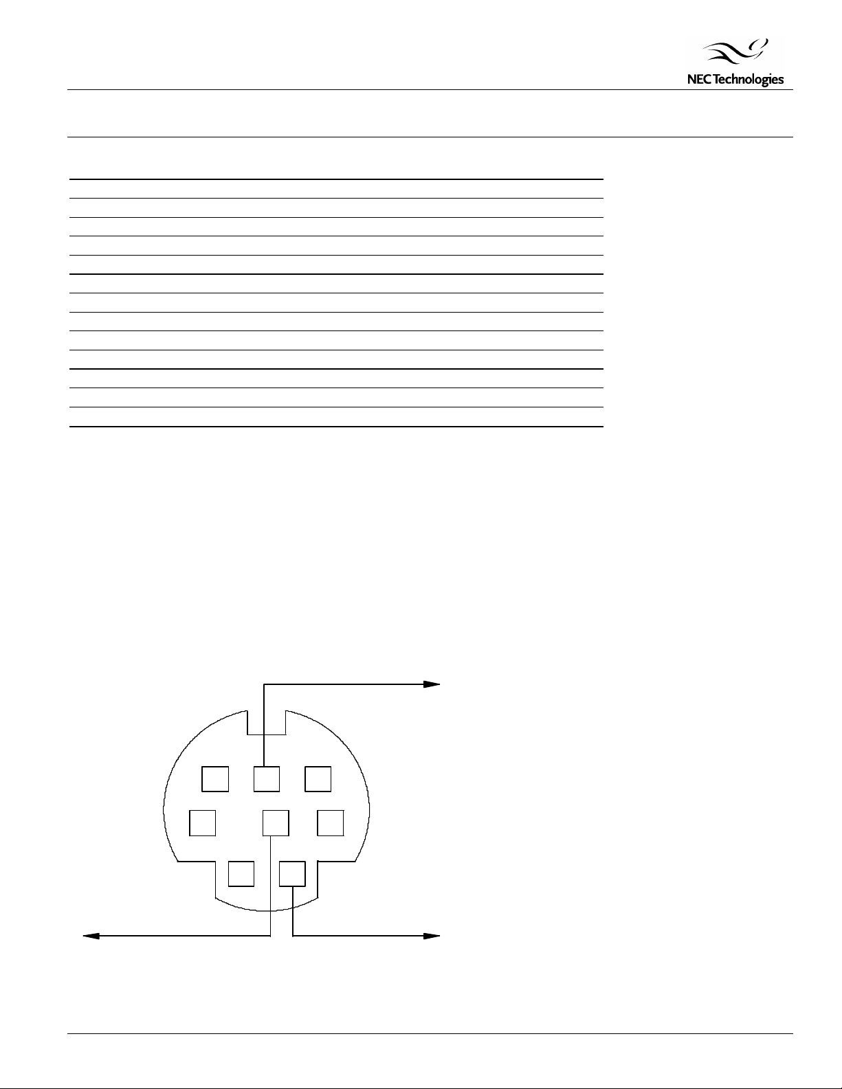
PC Control Connector (DIN-8P)
To RxD of PC
678
345
12
To GND of PC
NOTE: Pins 2, 3, 5, 6 and 8 are used inside the projector.
To TxD of PC
Page 7
 Loading...