

CD-ROM version
Portable Projector
LT260K/LT240K
User’s Manual
About this user's manual
The fastest way to get started is to take your time and do everything right the first time. Take a few minutes now to review the
user's manual. This may save you time later on. At the beginning of each section of the manual you'll find an overview. If the
section doesn't apply, you can skip it.

INTRODUCTION
Introduction to the Projector
This section introduces you to your new LT260K/LT240K Projector and
describes the features and controls.
Congratulations on Your Purchase of The LT260K/
LT240K Projector
The LT260K/LT240K is one of the very best projectors available today. The
LT260K/LT240K enables you to project precise images up to 500 inches
across (measured diagonally) from your PC or Macintosh computer (desktop or notebook), VCR, DVD player, document camera, a laser disc player
or Viewer.
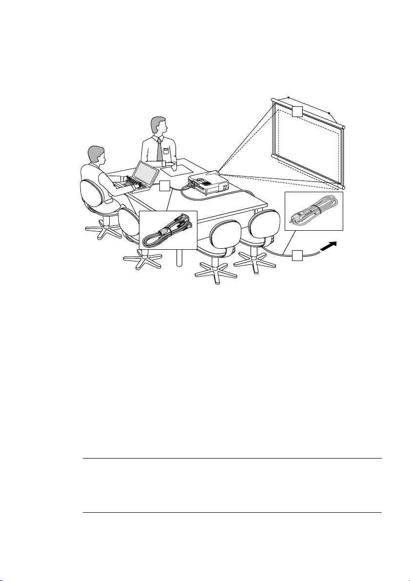
You can use the projector on a tabletop or cart, you can use the projector
to project images from behind the screen, and the projector can be permanently mounted on a ceiling*1. The remote control can be used wirelessly.
*1Do not attempt to mount the projector on a ceiling yourself.
The projector must be installed by qualified technicians in order to ensure proper operation and reduce the risk of bodily injury.
In addition, the ceiling must be strong enough to support the projector
and the installation must be in accordance with any local building codes.
Please consult your dealer for more information.
Features you'll enjoy:
• The newly developed 3D Reform function allows you to correct trapezoidal distortion for both horizontally and vertically so that the image is square even when projector is positioned off center of the
rooms screen.
• The LT260K/LT240K projector provides wired and wireless networking. When using as a wireless LAN projector, no physical signal cable
connection to a PC is required.*
*2A wireless LAN card is required. The NEC optional wireless LAN card is
available. (SWL-2100N-N
E-2
2
)
∗

INTRODUCTION ⬎ Introduction to the Projector
• Safety protect by Password and Security functions
Password and Security features prevent the projector from being used
by unauthorized individuals.
Password prevents unauthorized individuals from changing projector
settings or adjustments. Security offers complete protection by using
your PC card as a protect key so that the projector will not project a
signal without insertion of the registered PC card and unauthorized
use can be discouraged.
• The built-in Viewer allows you to start your presentation even when a
PC is not available at the site.
•A high-bright 220 watt DC lamp.
• The Standby mode reduces standby power consumption significantly.
• The supplied wireless remote control that operates the projector from
the front side or rear.
• The image can be projected between 30 and 500 inches (measured
diagonally).
• The "Capture" enables you to capture the current projected image.
• An image can be projected from in front or behind a screen, and the
projector can even be installed on the ceiling.
• NEC’s exclusive Advanced AccuBlend intelligent pixel blending technology - an extremely accurate image compression technology - offers a crisp image with UXGA (1600⳯1200) resolution*3.
• Supports most IBM VGA, SVGA, XGA , SXGA/UXGA(with Advanced
AccuBlend)*3, Macintosh, component signal (YCbCr/ YPbPr) or any
other RGB signals within a horizontal frequency range of 24 to 100
kHz and a vertical frequency range of 50 to 120 Hz. This includes
NTSC, PAL, PAL-N, PAL-M, PAL60, SECAM and NTSC4.43 standard video signals.
*3A UXGA (1600⳯1200) and SXGA image (1280⳯1024) are displayed
with NEC’s Advanced AccuBlend on LT260K/LT240K.
E-3

INTRODUCTION ⬎ Introduction to the Projector
NOTE: Composite video standards are as follows:
NTSC: U.S. TV standard for video in U.S. and Canada.
PAL: TV standard used in Western Europe.
PAL-N: TV standard used in Argentine, Paraguay and Uruguay.
PAL-M: TV standard used in Brazil.
PAL60: TV standard used for NTSC playback on PAL TVs.
SECAM: TV standard used in France and Eastern Europe.
NTSC4.43: TV standard used in Middle East countries.
E-4

INTRODUCTION ⬎ Introduction to the Projector
• The supplied remote control can be used without a cable, and you
can even use the remote control to operate your PC's mouse wirelessly
from across the room with the built-in remote mouse function.
•You can control the projector with a PC using the PC Control port.
• USB port allows USB mouse operation*4.
*4The USB ports meet the USB1.1 specification.
• The contemporary cabinet design is light, compact, easy to carry,
and complements any office, boardroom or auditorium.
• Nine pointers are available for your presentation.
E-5
INTRODUCTION ⬎ Part Names of the Projector
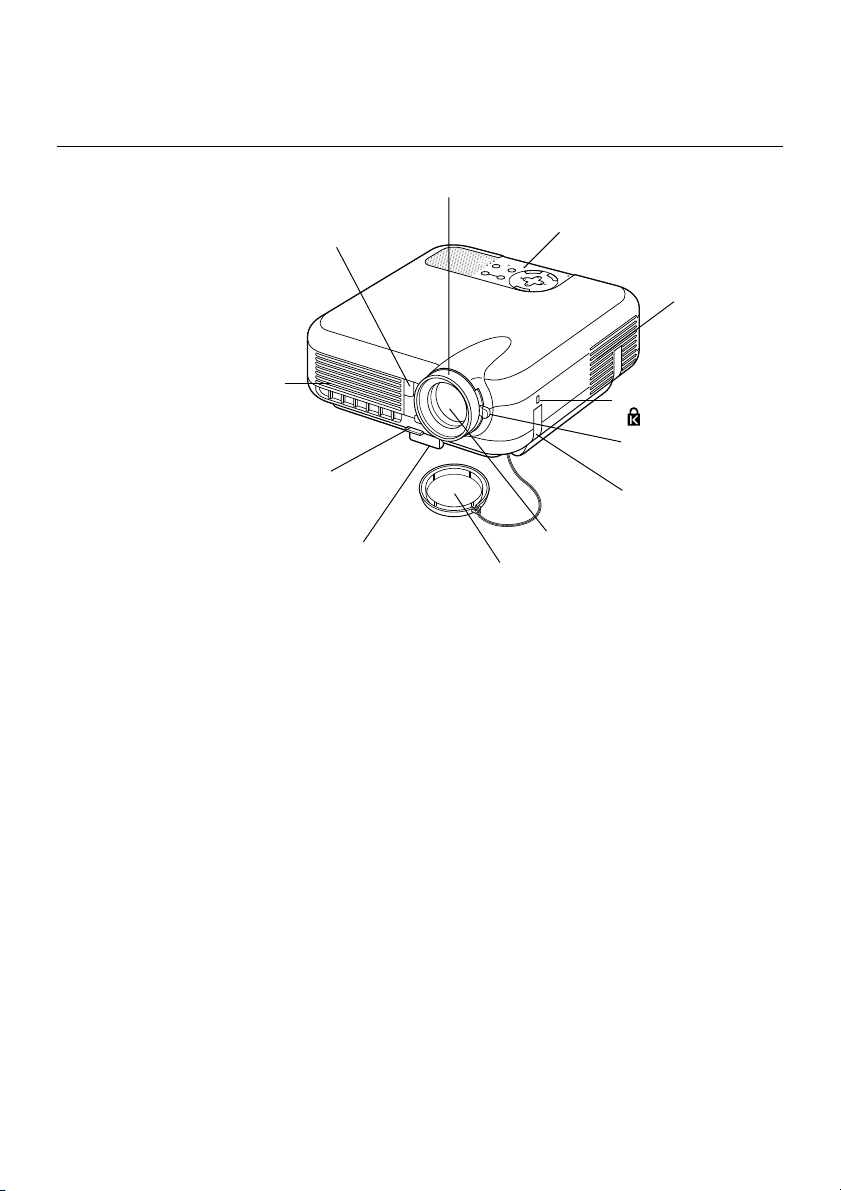
Part Names of the Projector
Focus Ring
(See page E-43)
Remote Sensor
(See page E-20)
Controls
(See page E-8)
POWER
Y
B
STATUS
D
N
A
T
S
N
LAMP
O
T
N
E
M
N
G
I
L
A
T
S
U
J
D
A
O
T
C
N
E
A
U
L
C
A
E
D
C
R
R
A
U
-C
O
C
S
P
R
E
T
N
E
T
C
E
L
E
S
U
N
E
M
Ventilation (inlet)
Ventilation (outlet)
Heated air is exhausted
from here
Built-in Security Slot
( )*
Zoom Lever
Adjustable Tilt Foot Lever
(See page E-43)
(See page E-42)
Adjustable Tilt Foot
(See page E-42)
Lens
Lens Cap
Carrying Handle
* This security slot supports the MicroSaver® Security System.
MicroSaver
®
is a registered trademark of Kensington Microware Inc.
The logo is trademarked and owned by Kensington Microware Inc.
E-6
INTRODUCTION ⬎ Part Names of the Projector
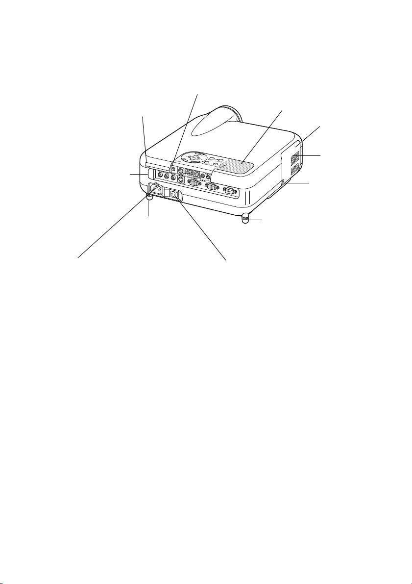
PC Card Eject Button
PC Card Slot
Remote Sensor
(See page E-20)
Rear Foot
AC Input
Connect the supplied power cable's three-pin
plug here, and plug the other end into an active
wall outlet.
(See page E-35)
Monaural Speaker (2W)
Lamp cover
(See page E-121)
Ventilation
(outlet)
Lamp cover screw
Rear Foot
Rotate to make the projector level.
(See page E-43)
Main Power Switch
When you plug the supplied power cable into an active wall outlet and turn on the Main Power switch,
the POWER indicator turns orange and the projector
is in standby mode.
(See page E-36)
E-7
INTRODUCTION ⬎ Part Names of the Projector
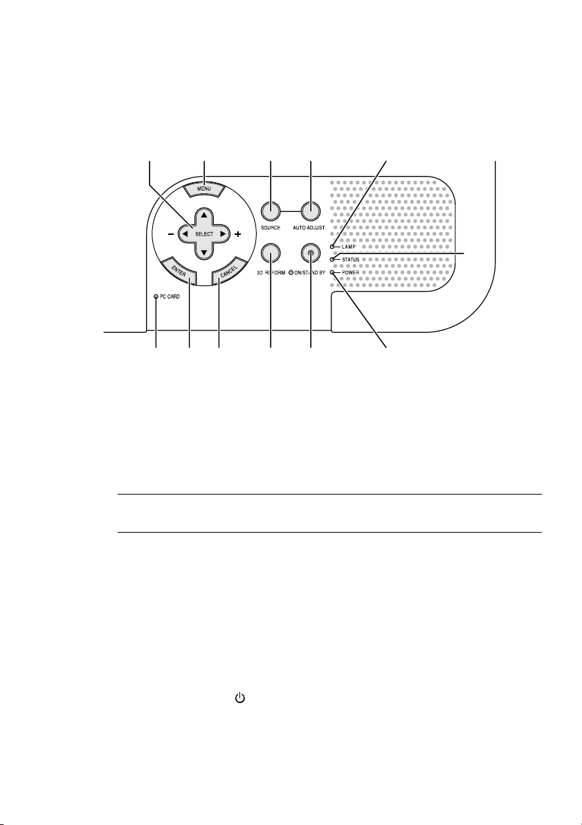
Top Features
910 45 11
678 121 3
1.POWER Button (ON / STAND BY)
Use this button to turn the power on and off when the main power is
supplied and the projector is in standby mode.
2
NOTE: To turn on or off the projector, press and hold this button for a mini-
mum of two seconds.
2. STATUS Indicator
If this light blinks red rapidly, it indicates that an error has occurred, the
lamp cover is not attached properly or the projector has overheated. If
this light remains orange, it indicates that you have pressed a cabinet
key while the Control Panel Key Lock is enabled. See the Status Indicator section on page E-126 for more details.
3. POWER Indicator ( )
When this indicator is green, the projector is on; when this indicator is
orange, it is in standby or idle mode. See the Power Indicator section
on page E-126 for more details.
E-8

INTRODUCTION ⬎ Part Names of the Projector ⬎ Top Features
4. SOURCE Button
Use this button to select a video source such as a PC, VCR, DVD
player, Viewer (PC card), or LAN.
Press and release this button quickly to display the Source List.
Each time this button is pressed for a minimum of ONE second, the
input source will change as follows:
RGB1 → RGB2 → Video → S-Video → Viewer → RGB1 → ...
If no input signal is present, the input will be skipped.
5. AUTO ADJUST Button
Use this button to adjust Position-H/V and Pixel Clock/Phase for an
optimal picture. Some signals may not be displayed correctly or take
time to switch between sources.
6. PC CARD Access Indicator
Lights while accessing a PC card.
7. ENTER Button
Executes your menu selection and activates items selected from the
menu.
8. CANCEL Button
Press this button to exit "Menus". Press this button to return the adjustments to the last condition while you are in the adjustment or setting
menu.
9. SELECT (+) (–) / Volume Buttons
: Use these buttons to select the menu of the item you wish to
adjust. When no menus appear, these buttons work as a volume
control.
E-9

INTRODUCTION ⬎ Part Names of the Projector ⬎ Top Features
: Use these buttons to change the level of a selected menu item.
A press of the button executes the selection. When the menus
or the Viewer tool bar is not displayed, these buttons can be
used to select a slide, or to move the cursor in Folder List or
Slide List.
When the pointer is displayed, these buttons move the pointer.
10. MENU Button
Displays the menu.
11. LAMP Indicator
If this light blinks red rapidly, it's warning you that the projection lamp
has exceeded 2000 hours (up to 3000 hours in Eco mode) of service.
After this light appears, replace the lamp as soon as possible. (See
page E-121). If this is lit green continually, it indicates that the lamp
mode is set to Eco. See the Lamp Indicator section on page E-127 for
more details.
12. 3D REFORM Button
Press this button to enter 3D Reform mode to correct the keystone
(trapezoidal) distortion, and make the image square.
E-10
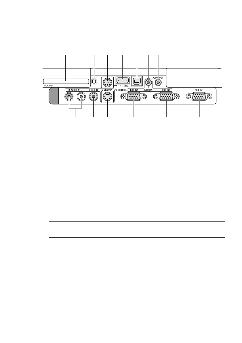
INTRODUCTION ⬎ Part Names of the Projector ⬎ Terminal Panel Features
Terminal Panel Features
10 11 3 5
91213
1. RGB IN 1 / Component Input Connector (Mini D-Sub 15 Pin)
Connect your computer or other analog RGB equipment such as IBM
compatible or Macintosh computers. Use the supplied RGB cable to
connect to your computer. This also serves as a component input connector that allows you to connect a component video output of component equipment such as a DVD player. This connector also supports
SCART output signal. See page E-28 for more details.
421678
2. RGB IN 2 / Component Input Connector (Mini D-Sub 15 Pin)
This connector has the same function as the RGB IN 1 connector.
NOTE: The RGB IN 2 does not support SCART output signal and Plug &
Play.
3. RGB AUDIO IN Mini Jack (Stereo Mini)
This is where you connect audio output from your computer or DVD
player. A commercially available audio cable is required.
4. RGB OUT Connector (Mini D-Sub 15 Pin)
You can use this connector to loop your computer image to an external
monitor from the RGB 1 or 2 input source.
The RGB analog signal set on RGBOUT Terminal is output during idle
mode. See pages E-31 and 100.
E-11

INTRODUCTION ⬎ Part Names of the Projector ⬎ Terminal Panel Features
5. AUDIO OUT Mini Jack (Stereo Mini)
Connect an additional audio equipment here to listen to audio coming
from your computer, Video or S- Video input.
Note that there is no audio output from this jack during Standby and
Idle.
6 S-VIDEO IN Connector (Mini DIN 4 Pin)
Here is where you connect the S-Video input from an external source
like a VCR.
NOTE: S-Video provides more vivid color and higher resolution than the tra-
ditional composite video format.
7. VIDEO IN Connector (RCA)
Connect a VCR, DVD player, laser disc player, or document camera
here to project video.
8. VIDEO AUDIO IN Jacks (RCA)
L : This is your left channel audio input for stereo sound coming from
the VIDEO source.
R : This is your right channel audio input for stereo sound from the
VIDEO source.
9. PC CONTROL Port (Mini DIN 8 Pin)
Use this port to connect your PC to control your projector via a serial
cable. This enables you to use your PC and serial communication protocol to control the projector. The NEC optional serial cable (CA03D) is
required to use this port. You can also control the projector by using
Dynamic Image Utility 2.0 included on the supplied CD-ROM.
To do so you must first have Dynamic Image Utility 2.0 installed on your
PC. If you are writing your own program, typical PC control codes are
on page E-136. A cap is put on the port at the factory. Remove the cap
when using the port.
E-12

INTRODUCTION ⬎ Part Names of the Projector ⬎ Terminal Panel Features
10. USB Port (Type A)
Connect a commercially available mouse that supports USB. You can
operate the menu or Viewer with the USB mouse via this port.
Note that this port should not be connected to a computer and that
there may be some brands of USB mouse that the projector does not
support.
11. USB Port (Type B)
Connect this port to the USB port (type A) of your PC using the supplied USB cable. You can operate your computer's mouse functions
from the remote control.
12. PC CARD Eject Button
Press to eject a PC card partially.
13. PC CARD Slot
Insert a PC card, commercially available LAN card or NEC optional
wireless LAN card here.
E-13
INTRODUCTION ⬎ Part Names of the Remote Control
A
NIF
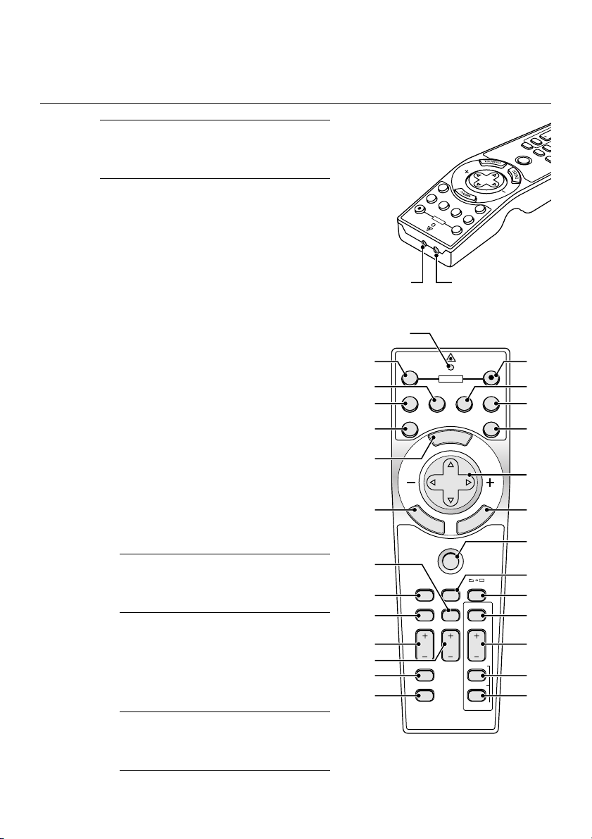
Part Names of the Remote Control
NOTE: If you are using a Macintosh com-
puter, you can click either the right-click
or left-click button to activate the mouse.
1. Infrared Transmitter
Direct the remote control toward
the remote sensor on the projector
cabinet.
2. LASER Pointer
Beams a laser light when the LASER button is pressed.
3. LED
Flashes when any button is
pressed.
4. POWER ON Button
If the main power is applied, you
can use this button to turn your projector on.
NOTE: To turn on the projector, press
and hold the POWER ON button for a
minimum of two seconds.
5. POWER OFF Button
You can use this button to turn your
projector off.
NOTE: To turn off the projector, press
and hold the POWER OFF button for
a minimum of two seconds.
12
21
17
20
22
23
24
25
5
7
LASER
RGB2
RGB1
ON
POWER
2 1
3
OFF
POWER
VIDEO
S-VIDEO RGB1 RGB2
AUTO ADJ.
E
M
SELECT
E
N
T
E
R
PJ
ASPECT
FREEZE
HELP
POINTER
VOLUME MAGNIFY
PICTURE
PIC-MUTE
OFF
N
U
S-VIDEO
VIDEO
A
C
3D REFORM
VIEWER
SLIDE
FOLDER
SLIDE
SLIDE
R
E
W
Y
IE
V
3D REFORM
INTER
PO
E
Z
E
E
R
F
SPECT
PJ
SELECT
AUTO ADJ.
4
ON
8
LASER
96
1110
13
L
E
C
N
1514
16
18
19
26
27
28
LIST
29
E-14

INTRODUCTION ⬎ Part Names of the Remote Control
6. VIDEO Button
Press this button to select an NTSC, PAL, PAL-N, PAL-M, PAL60,
SECAM or NTSC4.43 compatible video source from a VCR, DVD player,
or laser disc player.
7. S-VIDEO Button
Press this button to select an S-Video source from a VCR.
8. RGB 1 Button
Press this button to select a video source from computer or component
equipment connected to your RGB IN 1 port.
9. RGB 2 Button
Press this button to select a video source from computer or component
equipment connected to your RGB IN 2 port.
10. AUTO ADJ Button
Use this button to adjust an RGB source for an optimal picture. Some
signals may not be displayed correctly or take time to be displayed.
See page E-47.
11. LASER Button
Press and hold this button to activate the laser pointer. When lit, you
can use the laser to draw your audience's attention to a red dot that
you can place on any object.
12. MENU Button
Displays the menu for various settings and adjustments.
E-15

INTRODUCTION ⬎ Part Names of the Remote Control
13. SELECT (Mouse) Button
When you are in the Computer mode, these buttons work as a computer mouse. When you are in the Projector mode, which is indicated
by lighting the PJ button. See page E-52.
: Use these buttons to select the menu of the item you wish to
adjust.
: Use these buttons to change the level of a selected menu item.
A press of the button executes the selection.
When the pointer is displayed, these buttons move the pointer.
When the pointer is not displayed, these buttons are for adjust-
ing the image.
14. ENTER (Left Click) Button
When you are in the Computer mode, this button works as the mouse
left button. When this button is pressed and held for a minimum of 2
seconds, the drag mode is set. When you are in the Projector mode,
which is indicated by lighting the PJ button:
Use this button to enter your menu selection. It works the same way as
the ENTER button on the cabinet. See page E-9.
15. CANCEL (Right Click) Button
When you are in the Computer mode, this button works as the mouse
right button. When you are in the Projector mode, which is indicated by
lighting the PJ button: Press this button to exit the Menus. It works the
same way as the CANCEL button on the cabinet.
16. PJ Button
Press this button to switch the SELECT, CANCEL, and ENTER buttons between the Projector mode (lit red) and the Computer mode.
Press this button or any one of the POWER ON/OFF, MENU, ASPECT,
3D REFORM, HELP, POINTER, MAGNIFY, PICTURE, VIEWER,
FOLDER LIST or SLIDE LIST buttons to switch to the Projector mode
and the PJ button lights red. To switch back to the Computer mode,
press the PJ button again. See page E-52.
E-16

INTRODUCTION ⬎ Part Names of the Remote Control
17. ASPECT Button
Press this button to display the Aspect Ratio select screen. See page
E-86.
18. FREEZE Button
This button will freeze a picture. Press again to resume motion.
19. 3D REFORM Button
Press this button to enter 3D Reform to correct the keystone (trapezoidal) distortion, and make the image square. See page E-44.
20. HELP Button
Provides the online help or the set information.
21. POINTER Button
Press this button to display one of the eight pointers; press again to
hide the pointer. You can move your pointer icon to the area you want
on the screen using the Select button. See page E-54.
22. VOLUME (+) (–) Button
Press (+) to increase the volume and (–) to decrease it.
23. MAGNIFY (+) (–) Button
Use this button to adjust the image size up to 400%. When the pointer
is displayed, the image is magnified about the center of the pointer.
When the pointer is not displayed, the image is magnified about the
center of the screen. When the image is magnified, the pointer is
changed to the magnifying icon. See page E-55.
24. PICTURE Button
Press this button to display the Picture adjustement screen such as
Brightness, Contrast, Color, Hue, and Sharpness. See page E-85.
E-17

INTRODUCTION ⬎ Part Names of the Remote Control
25. PICTURE MUTE Button
This button turns off the image and sound for a short period of time.
Press again to restore the image and sound.
NOTE: When the menu is displayed, a press of this button mutes an image and
sound without turning off the menu.
26. VIEWER Button
Press this button to select the Viewer source.
27. SLIDE (+) (–) Button
Press (+) to select the next folder or slide and (–) to select the previous
folder or slide. See page E-67.
28. FOLDER LIST Button
Press this button to select Viewer source to display a list of folders
included in a PC card. See page E-67.
29. SLIDE LIST Button
Press this button to select Viewer source to display a list of slides included in a PC card. See page E-67.
NOTE: The default is the Computer mode, which allows you to use the SE-
LECT, CANCEL, and ENTER buttons as your computer mouse. When the
POWER ON/OFF, MENU, ASPECT, 3D REFORM, HELP, POINTER, MAG-
NIFY, PICTURE, VIEWER, FOLDER LIST, or SLIDE LIST button is pressed,
the PJ button lights red to indicate that you are in the Projector mode. If no
buttons are pressed within 60 seconds, the light goes out and the Projector
mode is canceled.
E-18
INTRODUCTION ⬎ Part Names of the Remote Control
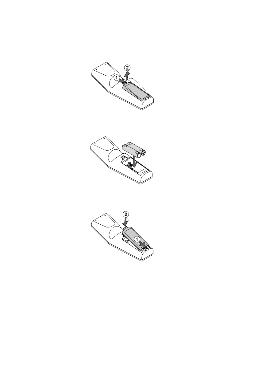
Battery Installation
1. Press the catch and remove the battery cover.
2. Remove both old batteries and install new ones (AA). Ensure that you
have the batteries' polarity (+/-) aligned correctly.
3. Slip the cover back over the batteries until it snaps into place. Do not mix
different types of batteries or new and old batteries.
Note on Remote Control Operation:
If you press and hold the SELECT button while installing new
batteries, the remote control may fail to work properly.
Should this happen, remove the batteries and then install them again without touching the SELECT button.
E-19
INTRODUCTION ⬎ Part Names of the Remote Control
Remote Control Precautions
• Handle the remote control carefully.
• If the remote control gets wet, wipe it dry immediately.
•Avoid excessive heat and humidity.
• If you will not be using the remote control for a long time, remove the
batteries.
• Do not place the batteries upside down.
• Do not use new and old batteries together, or use different types of
batteries together
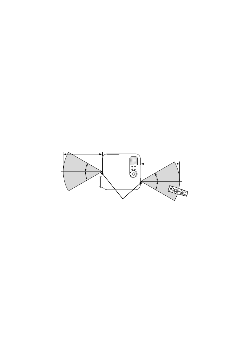
Operating Range
7m/22 feet
˚
30
˚
30
7m/22 feet
˚
30
˚
30
Remote sensor on the
Remote control
projector cabinet
• The infrared signal operates by line-of-sight up to a distance of about
22 feet/7 m and within a 60-degree angle of the remote sensor on the
projector cabinet.
• The projector will not respond if there are objects between the re-
mote control and the sensor, or if strong light falls on the sensor.
Weak batteries will also prevent the remote control from properly
operating the projector.
E-20
INSTALLATION AND CONNECTIONS
This section describes how to set up your projector and how to connect
video and audio sources.
1
2
3
To the wall outlet.
Your projector is simple to set up and use. But before you get started, you
must first:
z Set up a screen and the projector.
x Connect your computer or video equipment to the projector. See page E-
27.
c Connect the supplied power cable. See page E-35.
NOTE: Ensure that the power cable and any other cables are disconnected
before moving the projector.
When moving the projector or when it is not in use, cover the lens with the lens
cap.
E-21
INSTALLATION AND CONNECTIONS ⬎ Setting Up the Screen and theProjector
Setting Up the Screen and the Projector
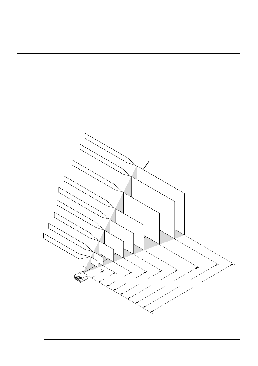
Selecting a Location
The further your projector is from the screen or wall, the larger the image.
The minimum size the image can be is approximately 30" (0.8 m) measured diagonally when the projector is roughly 4 feet (1.3 m) from the wall
or screen. The largest the image can be is 500" (12.7 m) when the projector is about 80.83 feet (24.64 m) from the wall or screen. Use the drawing
below as a guide.
Screen size (Unit: cm/inch)
406.4(W)
⳯304.8(H)/160"(w)
81.3(W)
61.0(W)
⳯45.7(H)/24"(W)
243.8(W)
203.2(W)
⳯152.4(H)/80"(W)
162.6(W)
⳯121.9(H)/64"(W)
121.9(W)
⳯91.4(H)/48"(W)
⳯61.0(H)/32"(W)
⳯18"(H)
Lens center
365.8(W)
⳯274.3(H)/144"(W)
304.8(W)
⳯228.6(H)/120"(W)
⳯182.9(H)/96"(W)
⳯72"(H)
⳯60"(H)
⳯48"(H)
⳯36"(H)
⳯24"(H)
40"
30"
⳯90"(H)
60"
⳯108"(H)
80"
⳯120"(H)
Screen size
200"
180"
150"
120"
100"
1.3/4.3
(1.0/3.3)
1.7/5.6
2.6/8.5
(1.3/4.3)
(2.0/6.6)
3.5/11.5
(2.7/8.9)
4.4/14.4
(3.4/11.2)
NOTE: Values in parentheses for LT240K.
E-22
5.3/17.4
6.6/21.7
(4.1/13.5)
Distance (Unit: m/feet)
(5.2/17.1)
7.9/25.9
(6.2/20.34)
8.8/28.9
(6.9/22.6)
INSTALLATION AND CONNECTIONS ⬎ Setting Up the Screen and theProjector
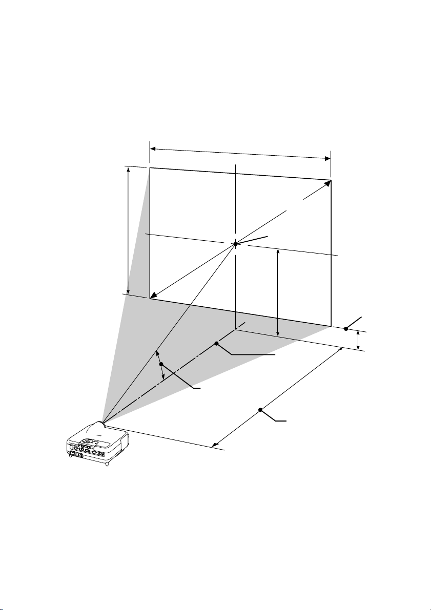
Throw Distance and Screen Size
The following shows the proper relative positions of the projector and screen.
Refer to the table to determine the position of installation.
Distance Chart
Screen Width
Screen Diagonal
Screen Height
Throw Angle (움)
Screen center
(B)
Lens Center
Throw Distance (C)
B = Vertical distance between lens center and screen center
C = Throw distance
D = Vertical distance between lens center and bottom of screen
α = Throw angle
Screen Bottom
(D)
E-23

INSTALLATION AND CONNECTIONS ⬎ Setting Up the Screen and theProjector
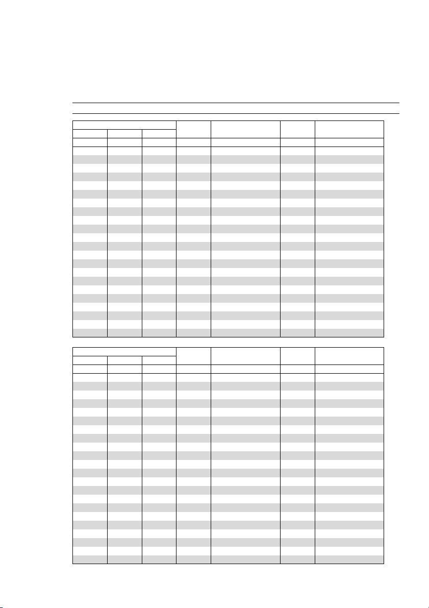
<LT260K>
B = Vertical distance between lens center and screen center
C = Throw distance
D = Vertical distance between lens center and bottom of screen
α = Throw angle
NOTE: Distances may vary +/-5%.
Screen Size B C
Diagonal Width Height
inch
30
40
60
67
72
80
84
90
100
120
150
180
200
210
240
261
270
300
350
400
450
500
inch
24
32
48
54
58
64
67
72
80
96
120
144
160
168
192
209
216
240
280
320
360
400
inch
18
24
36
40
43
48
50
54
60
72
90
108
120
126
144
157
162
180
210
240
270
300
inch
12.6
16.8
25.3
28.2
30.3
33.7
35.4
37.9
42.1
50.5
63.2
75.8
84.2
88.4
101.1
109.9
113.7
126.3
147.4
168.5
189.5
210.6
Wide – Tele
inch
46.4 – 57.0
62.4 – 76.4
94.5 – 115.3
105.8 – 128.9
113.8 – 138.6
126.6 – 154.1
133.0 – 161.9
142.7 – 173.6
158.7 – 193.0
190.8 – 231.8
239.0 – 290.1
287.1 – 348.4
319.2 – 387.2
335.3 – 406.7
383.4 – 464.9
417.1 – 505.7
431.6 – 523.2
479.7 – 581.5
560.0 – 678.6
640.2 – 775.7
720.5 – 872.9
800.7 – 970.0
inch
3.6
4.8
7.3
8.1
8.7
9.7
10.2
10.9
12.1
14.5
18.2
21.8
24.2
25.4
29.1
31.6
32.7
36.3
42.4
48.5
54.5
60.6
D
Wide – Tele
degree
15.2 - 12.5
15.1 - 12.4
15.0 - 12.4
14.9 - 12.3
14.9 - 12.3
14.9 - 12.3
14.9 - 12.3
14.9 - 12.3
14.9 - 12.3
14.8 - 12.3
14.8 - 12.3
14.8 - 12.3
14.8 - 12.3
14.8 - 12.3
14.8 - 12.3
14.8 - 12.3
14.8 - 12.3
14.8 - 12.3
14.7 - 12.3
14.7 - 12.3
14.7 - 12.2
14.7 - 12.2
α
Screen Size B C
Diagonal Width Height
mm
762
1016
1524
1702
1829
2032
2134
2286
2540
3048
3810
4572
5080
5334
6096
6629
6858
7620
8890
10160
11430
12700
mm
610
813
1219
1361
1463
1626
1707
1829
2032
2438
3048
3658
4064
4267
4877
5304
5486
6096
7112
8128
9144
10160
mm
457
610
914
1021
1097
1219
1280
1372
1524
1829
2286
2743
3048
3200
3658
3978
4115
4572
5334
6096
6858
7620
mm
321
428
642
716
770
855
898
962
1069
1283
1604
1925
2139
2246
2567
2792
2888
3209
3744
4279
4814
5349
1178 - 1448
1586 - 1942
2401 - 2928
2686 - 3274
2890 - 3520
3216 - 3915
3379 - 4113
3624 - 4409
4032 - 4902
4847 - 5889
6070 - 7369
7293 - 8849
8108 - 9836
8516 -10329
9739 -11810
10595 -12846
10962 -13290
12185 -14770
14223 -17237
16261 -19704
18299 -22171
20338 -24638
E-24
Wide – Tele
mm
D α
mm
92
123
184
206
221
246
258
277
307
369
461
554
615
646
738
803
831
923
1077
1231
1385
1539
Wide – Tele
degree
15.2 - 12.5
15.1 - 12.4
15.0 - 12.4
14.9 - 12.3
14.9 - 12.3
14.9 - 12.3
14.9 - 12.3
14.9 - 12.3
14.9 - 12.3
14.8 - 12.3
14.8 - 12.3
14.8 - 12.3
14.8 - 12.3
14.8 - 12.3
14.8 - 12.3
14.8 - 12.3
14.8 - 12.3
14.8 - 12.3
14.7 - 12.3
14.7 - 12.3
14.7 - 12.2
14.7 - 12.2
INSTALLATION AND CONNECTIONS ⬎ Setting Up the Screen and theProjector
<LT240K>
B = Vertical distance between lens center and screen center
C = Throw distance
D = Vertical distance between lens center and bottom of screen
α = Throw angle
NOTE: Distances may vary +/-5%.
Screen Size B C
Diagonal Width Height
inch
30
40
60
67
72
80
84
90
100
120
150
180
200
210
240
261
270
300
350
400
450
500
inch
24
32
48
54
58
64
67
72
80
96
120
144
160
168
192
209
216
240
280
320
360
400
inch
18
24
36
40
43
48
50
54
60
72
90
108
120
126
144
157
162
180
210
240
270
300
inch
12.6
16.8
25.2
28.1
30.2
33.6
35.3
37.8
42.0
50.4
63.0
75.6
84.0
88.2
100.8
109.7
113.4
126.1
147.1
168.1
189.1
210.1
Wide – Tele
inch
35.7 - 43.4
48.2 - 58.4
73.2 - 88.5
81.9 - 99.0
88.1 - 106.5
98.1 - 118.6
103.1 - 124.6
110.6 - 133.6
123.1 - 148.6
148.1 - 178.7
185.5 - 223.8
223.0 - 268.9
248.0 - 298.9
260.5 - 314.0
297.9 - 359.1
324.1 - 390.6
335.4 - 404.1
372.8 - 449.2
435.3 - 524.4
497.7 - 599.6
560.1 - 674.7
622.5 - 749.9
inch
3.6
4.8
7.2
8.0
8.6
9.6
10.1
10.8
12.0
14.4
18.0
21.6
24.0
25.2
28.8
31.4
32.4
36.1
42.1
48.1
54.1
60.1
D
Wide – Tele
degree
19.4 - 16.2
19.2 - 16.0
19.0 - 15.9
19.0 - 15.9
18.9 - 15.8
18.9 - 15.8
18.9 - 15.8
18.9 - 15.8
18.8 - 15.8
18.8 - 15.8
18.8 - 15.7
18.7 - 15.7
18.7 - 15.7
18.7 - 15.7
18.7 - 15.7
18.7 - 15.7
18.7 - 15.7
18.7 - 15.7
18.7 - 15.7
18.7 - 15.7
18.7 - 15.7
18.6 - 15.7
α
Screen Size B C
Diagonal Width Height
mm
762
1016
1524
1702
1829
2032
2134
2286
2540
3048
3810
4572
5080
5334
6096
6629
6858
7620
8890
10160
11430
12700
mm
610
813
1219
1361
1463
1626
1707
1829
2032
2438
3048
3658
4064
4267
4877
5304
5486
6096
7112
8128
9144
10160
mm
457
610
914
1021
1097
1219
1280
1372
1524
1829
2286
2743
3048
3200
3658
3978
4115
4572
5334
6096
6858
7620
mm
320
426
640
715
768
853
896
960
1067
1280
1601
1921
2134
2241
2561
2785
2881
3202
3735
4269
4803
5336
1224 - 1484
1858 - 2248
2080 - 2515
2239 - 2706
2493 - 3011
2620 - 3164
2810 - 3393
3127 - 3775
3761 - 4538
4713 - 5684
5664 - 6829
6298 - 7593
6615 - 7975
7567 - 9120
8233 - 9922
8518 -10265
9470 -11411
11055 -13320
12641 -15229
14227 -17138
15813 -19046
E-25
Wide – Tele
mm
907 - 1102
D α
mm
91
122
183
204
219
244
256
274
305
366
458
549
610
641
732
797
824
916
1068
1221
1374
1526
Wide – Tele
19.4 - 16.2
19.2 - 16.0
19.0 - 15.9
19.0 - 15.9
18.9 - 15.8
18.9 - 15.8
18.9 - 15.8
18.9 - 15.8
18.8 - 15.8
18.8 - 15.8
18.8 - 15.7
18.7 - 15.7
18.7 - 15.7
18.7 - 15.7
18.7 - 15.7
18.7 - 15.7
18.7 - 15.7
18.7 - 15.7
18.7 - 15.7
18.7 - 15.7
18.7 - 15.7
18.6 - 15.7
degree

INSTALLATION AND CONNECTIONS ⬎ Setting Up the Screen and theProjector
WARNING
* Installing your projector on the ceiling must be done by a qualified tech-
nician. Contact your NEC dealer for more information.
* Do not attempt to install the projector yourself.
• Only use your projector on a solid, level surface. If the projector falls to
the ground, you can be injured and the projector severely damaged.
• Do not use the projector where temperatures vary greatly. The projector
must be used at temperatures between 41˚F (5˚C) and 95˚F (35˚C).
• Do not expose the projector to moisture, dust, or smoke. This will harm
the screen image.
• Ensure that you have adequate ventilation around your projector so
heat can dissipate. Do not cover the vents on the side or the front of the
projector.
Reflecting the Image
Using a mirror to reflect your projector's image enables you to enjoy a
much larger image. Contact your NEC dealer if you need a mirror. If you're
using a mirror and your image is inverted, use the MENU and SELECT
buttons on your projector cabinet or buttons on your remote control to
correct the orientation. (See page E-95.)
E-26
INSTALLATION AND CONNECTIONS
Making Connections
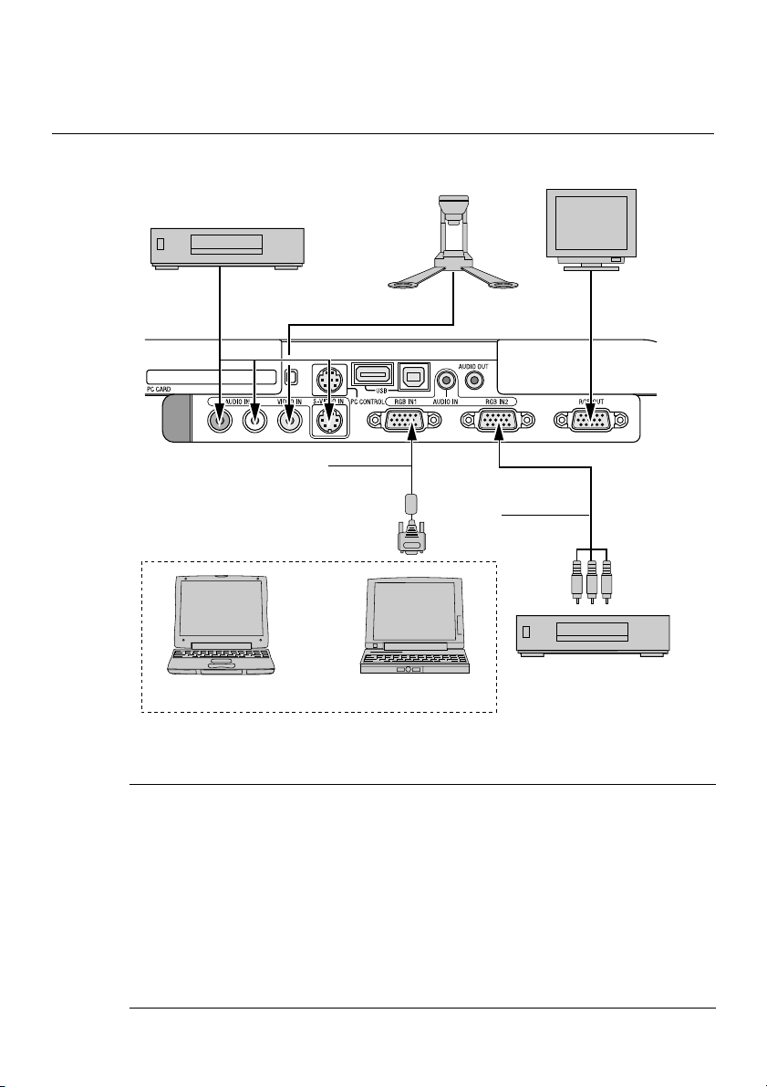
Wiring Diagram
VCR, DVD Player or
LaserDisc Player
To video, S-video, and audio inputs on the projector.
RGB Signal cable (supplied)
To mini D-Sub 15-pin connector on the projector. It is recommended that you use a commercially available distribution amplifier if connecting a signal cable longer than the supplied cable.
Macintosh
(Desktop type or notebook type)
IBM VGA or Compatibles
(Desktop type or notebook type)
Document Camera
Optional 15-pin-to-RCA
(female)⳯3 cable
(ADP-CV1)
Monitor
DVD Player
(with component output)
NOTE: When using with a notebook PC, be sure to connect between the projector
and the notebook PC before turning on the power to the notebook PC. In most
cases signal cannot be output from RGB output unless the notebook PC is turned
on after connecting with the projector.
* If the screen goes blank while using your remote control, it may be the result of
the computer's screen-saver or power management software.
* If you accidentally hit the POWER button on the remote control, wait 90 sec-
onds and then press the POWER button again to resume.
E-27
INSTALLATION AND CONNECTIONS ⬎ Making Connections
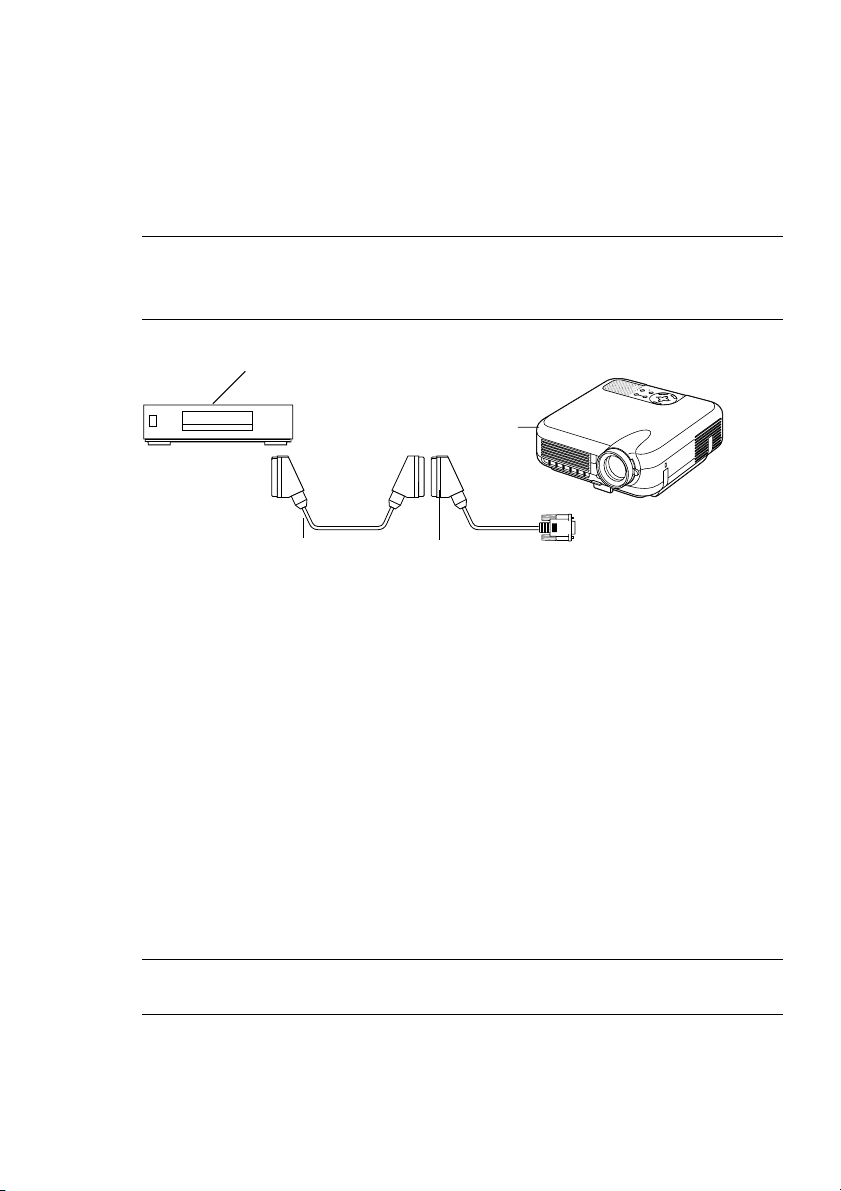
To connect SCART output (RGB)
Before connections: An exclusive SCART adapter (ADP-SC1) and a commercially available SCART cable are required for this connection.
NOTE:
•Audio signal is not available for this connection.
• The RGB IN 2 connector does not support SCART signal and Plug & Play.
Video equipment
such as DVD player
R
E
W
O
P
S
U
T
A
Y
T
B
S
D
N
A
P
T
M
S
A
N
L
O
T
N
E
M
N
G
I
L
A
T
S
U
J
D
A
O
T
C
N
E
A
U
L
C
A
E
D
C
R
R
A
U
C
-
O
C
S
P
R
E
T
N
E
T
C
E
L
E
S
U
N
E
M
Projector
To RGB IN 1
Commercially available SCART cable
Female
ADP-SC1
1. Turn off the power to the projector and your video equipment.
2. Use the NEC ADP-SC1 SCART adapter and a commercially available
SCART cable to connect the RGB 1 input of your projector and a SCART
output (RGB) of your video equipment.
3. Turn on the power to the projector and your video equipment.
4. Use the RGB 1 button on the remote control to select the RGB 1 input.
5. Press the MENU button on the remote control to display the menu.
6. From the Advanced menu, select [Projector Options] → [Setup] → [Page
3] → [Signal Select RGB1] → [Scart].
SCART is a standard European audio-visual connector for TVs, VCRs
and DVD players. It is also referred to as Euro-connector.
NOTE: The ADP-SC1 SCART adapter is obtainable from your NEC dealer in
Europe. Contact your NEC dealer in Europe for more information.
E-28
INSTALLATION AND CONNECTIONS ⬎ Making Connections
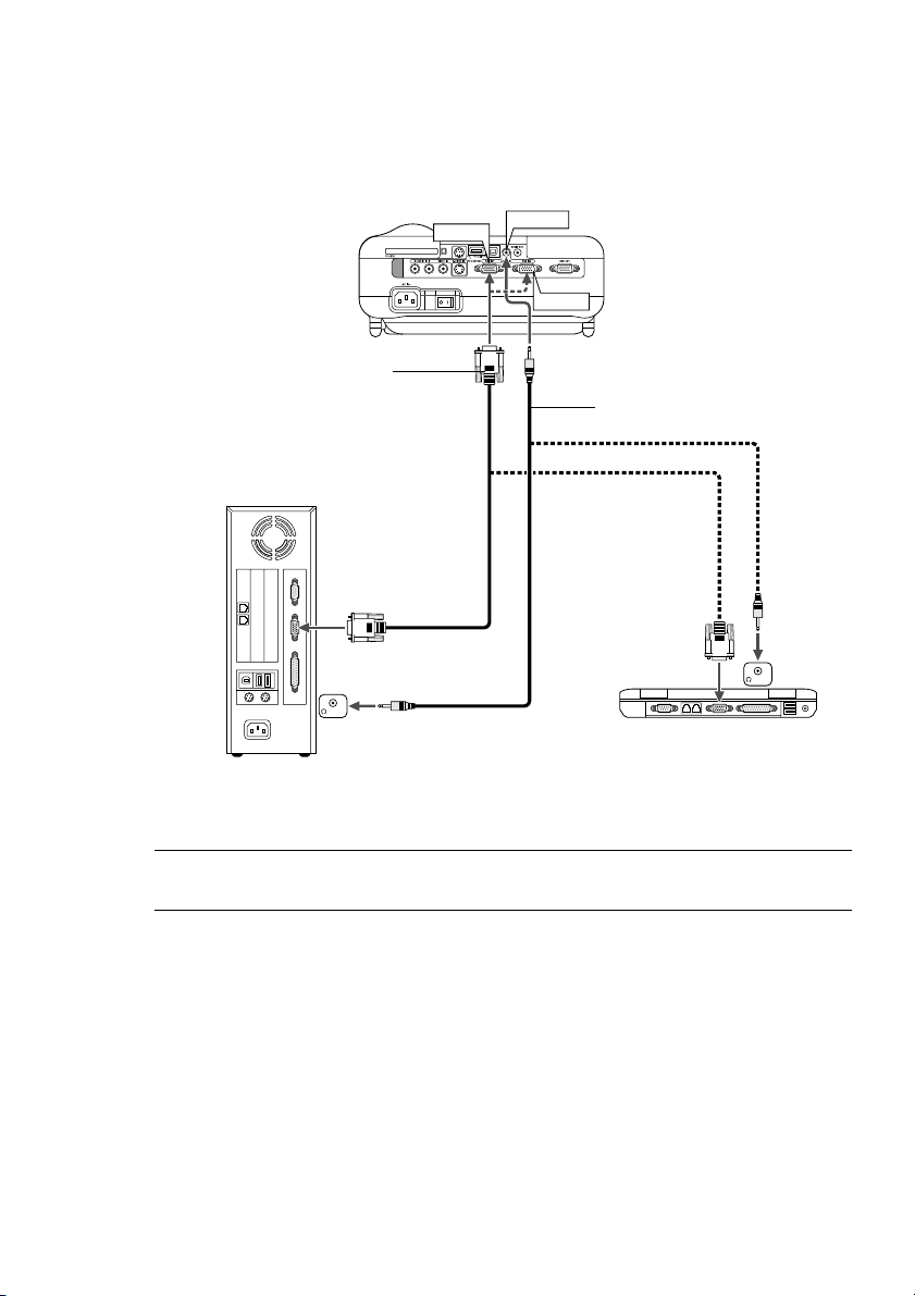
Connecting Your PC or Macintosh Computer
RGB IN1
RGB signal cable (supplied)
To mini D-Sub 15-pin connector on the
projector. It is recommended that you use
a commercially available distribution amplifier if connecting a signal cable longer
than the supplied one.
PHONE
IBM VGA or Compatibles (Desktop type)
or Macintosh (Desktop type)
AUDIO IN
RGB IN2
Audio cable (not supplied)
PHONE
IBM VGA or Compatibles (Notebook type) or Macintosh (Notebook type)
NOTE: For older Macintosh, use a commercially available pin adapter (not sup-
plied) to connect to your Mac's video port.
E-29

INSTALLATION AND CONNECTIONS ⬎ Making Connections
Connecting your PC or Macintosh computer to your projector will enable
you to project your computer's screen image for an impressive presentation.
To connect to a PC or Macintosh, simply:
1. Turn off the power to your projector and computer.
2. Use the supplied signal cable to connect your PC or Macintosh to the
projector.
3. Turn on the projector and the computer.
4. If the projector goes blank after a period of inactivity, it may be caused
by a screen saver installed on the computer you've connected to the projector.
NOTE: The LT260K/LT240K is not compatible with video decoded outputs of
NEC ISS-6020 and ISS-6010.
E-30

INSTALLATION AND CONNECTIONS ⬎ Making Connections
Connecting an External Monitor
RGB OUT
You can connect a separate, external monitor to your projector to simultaneously view on a monitor the RGB analog image you're projecting. To do
so:
1. Turn off the power to your projector, monitor and computer.
2. Use a 15-pin cable to connect your monitor to the RGB OUT (Mini D-Sub
15 pin) connector on your projector.
3. Turn on the projector, monitor and the computer.
NOTE: The RGB OUT connector outputs RGB signal during idle mode (See page
E-100). When the projector goes into idle mode, the image on an external monitor
disappears for a moment. Note that the RGB OUT connector will not output RGB
signal during Standby mode.
• Daisy chain connection is not possible.
E-31

INSTALLATION AND CONNECTIONS ⬎ Making Connections
RGB IN1 or IN2
AUDIO OUT
RL
COMPONENT OUT
AUDIO IN
LR
Connecting Your Video Equipment
Connecting Your DVD Player
Optional 15-pin-to-RCA
(female)⳯3 cable (ADP-CV1)
Component video
RCA⳯3 cable
(not supplied)
DVD player
Audio cable (not supplied)
Audio Equipment
You can connect your projector to a DVD player with component output or
Video output. To do so, simply:
1. Turn off the power to your projector and DVD player.
2. If your DVD player has the component video (Y,Cb,Cr) output, use a commercially available component video cable (RCA⳯3) and the optional
15-pin-to-RCA (female)⳯3 cable to connect your DVD player to the RGB
IN1 or IN2 connector on the projector.
For a DVD player without component video (Y,Cb,Cr) output, use common RCA cables (not provided) to connect a composite VIDEO output of
the DVD player to the Video Input of the projector.
3. Turn on the projector and DVD player.
NOTE: Refer to your DVD player's owner's manual for more information about
your DVD player's video output requirements,
E-32

INSTALLATION AND CONNECTIONS ⬎ Making Connections
VIDEO IN S-VIDEO IN
AUDIO OUT
RL
VIDEO OUT
S-VIDEO OUT
AUDIO IN
LR
Connecting Your VCR or Laser Disc Player
Video cable (not supplied)
VCR/ Laser disc player
Audio cable (not supplied)
Use common RCA cables (not provided) to connect your VCR, laser disc
S-video cable (not supplied)
Audio equipment
player or document camera to your projector.
To make these connections, simply:
1. Turn off the power to the projector and VCR, laser disc player or document camera.
2. Connect one end of your RCA cable to the video output connector on the
back of your VCR or laser disc player, connect the other end to the Video
input on your projector. Use an audio cable (not supplied) to connect the
audio from your VCR or laser disc player to your audio equipment (if
your VCR or laser disc player has this capability). Be careful to keep your
right and left channel connections correct for stereo sound.
E-33

INSTALLATION AND CONNECTIONS ⬎ Making Connections
3. Turn on the projector and the VCR or laser disc player.
NOTE: Refer to your VCR or laser disc player owner's manual for more informa-
tion about your equipment's video output requirements.
NOTE: An image may not be displayed correctly when a Video or S-Video source
is played back in fast-forward or fast-rewind via a scan converter.
E-34

INSTALLATION AND CONNECTIONS ⬎ Making Connections
Connecting the Supplied Power Cable
Connect the supplied power cable to the projector.
First connect the supplied power cable's three-pin plug to the AC IN of the
projector, and then connect the other plug of the supplied power cable in
the wall outlet.
E-35

PROJECTING AN IMAGE
(BASIC OPERATION)
This section describes how to turn on the projector and to project a picture
onto the screen.
Tur ning on the Projector
NOTE:
• When plugging in or unplugging the supplied power cable, make sure that the
main power switch is pushed to the off[O] position. Failure to do so may
cause damage to the projector.
• The projector has two power switches: main power switch and POWER but-
ton (POWER ON and OFF on the remote control)
• The projector has a feature to prevent itself from being used by unauthorized
individuals. To use this feature, register your PC card as a protect key. See
"Security" in "Projector Options" on page E-114 for more details.
To turn on the main power to the projector, press the Main Power switch to
the ON position ( I ).
Before you turn on your projector, ensure that the computer or video source
is turned on and that your lens cap is removed.
Only after you press the ON/STAND BY button on the projector cabinet or
POWER ON button on the remote control for a minimum of 2 seconds will
the power indicator turn to green and the projector become ready to use.
E-36

PROJECTING AN IMAGE ⬎ Turning on the Projector
Note on Startup screen (Menu Language Select screen)
When you first turn on the projector, you will get the Startup screen. This
screen gives you the opportunity to select one of the seven menu languages: English, German, French, Italian, Spanish, Swedish and Japanese.
To select a menu language, follow these steps:
1. Use the SELECT or button to select one of the seven languages for
the menu.
N
E
U
M
SELECT
E
N
T
E
R
L
E
C
N
A
C
2. Press the ENTER button to execute the selection.
N
E
U
M
SELECT
E
N
T
E
R
L
E
C
N
A
C
E-37

PROJECTING AN IMAGE ⬎ Turning on the Projector
3. The Basic menu will be displayed in the language you have selected.
N
E
U
M
SELECT
E
N
T
E
R
L
E
C
N
A
C
To close the menu, press the CANCEL button.
After this has been done, you can proceed to the advanced menu operation.
If you want, you can select the menu language later. See "Language" on
page E-93.
NOTE: To turn the projector on by plugging in the power cable, first turn on the
Main Power switch to ON and use the menu and enable the "Auto Start" feature.
(See page E-99.)
Immediately after turning on the projector, screen flicker may occur. This is not a
fault. Wait 3 to 5 minutes until the lamp lighting is stabilized.
When the Lamp mode is set to Eco, the Lamp indicator will light green.
If one of the following things happens, the projector will not turn on.
* If the internal temperature of the projector is too high, the projector
detects abnormal high temperature. In this condition the projector
will not turn on to protect the internal system. If this happens, wait for
the projector's internal components to cool down.
* When the lamp reaches its end of usable life, the projector will not
turn on. If this happens, replace the lamp.
* If the lamp fails to light, and if the STATUS indicator flashes on and
off in a cycle of six times, wait a full minute and then turn on the
power.
E-38

PROJECTING AN IMAGE
Selecting a Source
Selecting the computer or video source
Using the Remote Control
OFF
ON
POWER
VIDEO
S-VIDEO RGB1 RGB2
AUTO ADJ.
LASER
ASPECT
3D REFORM
FREEZE
HELP
POINTER
VIEWER
SLIDE
VOLUME MAGNIFY
PICTURE
FOLDER
SLIDE
PIC-MUTE
LIST
NOTE: If no input signal is available, the projector will display a blue back-
ground (factory preset).
Press any one of the RGB1,
RGB2, VIDEO, S-VIDEO or
VIEWER buttons.
Selecting from Source List
Source List
Press and quickly release the SOURCE button on the projector cabinet to display the Source list. Each time the SOURCE button is pressed,
the input source will change as follows: "Video" (VCR, document camera, or laser disc player), S-Video", "RGB1" or "RGB2" (computer or
DVD with component output) , "Viewer" (slides on a PC card), or "LAN"
(wired or wireless signal aired from a PC).
To display the selected source, press the ENTER button.
E-39

PROJECTING AN IMAGE ⬎ Selecting a Source
Detecting the Signal Automatically
Press and hold the SOURCE button for a minimum of ONE second,
the projector will search for the next available input source. Each time
you press and hold the SOURCE button, the input source will change
as follows:
→ RGB1 → RGB2 → Video → S-Video → Viewer
If no input signal is present, the input will be skipped. When the input
source you wish to project is displayed, release the button.
Press the ENTER button.
E-40

PROJECTING AN IMAGE
Adjusting the Picture Size and Position
Place your projector on a flat level surface and ensure that the projector is
square to the screen.
Lift the front edge of the projector to center the image vertically.
Move the projector left to center the image horizontally on the screen.
Use the 3D REFORM feature for proper adjustment. See page E-44.
Geometric Correction Tool
If you use a special shaped screen such as a cylindrical or spherical
screen, a downloadable program, Geometric Correction Tool is available.
This program (Geometric Correction Tool) enables the geometrical distortion correction of an image when projected onto a special shaped screen
with a NEC projector. Additionally, this program allows control of the projector via a computer.
For additional information visit:
US : http://www.necvisualsystems.com
Europe : http://www.nec-europe.com/
Global : http://www.nec-pj.com/
E-41

PROJECTING AN IMAGE ⬎ Adjusting the Picture Size and Position
Adjust the Tilt Foot
q Lift the front edge of the projector.
R
E
W
O
P
S
U
T
A
Y
T
B
S
D
N
A
P
T
M
S
A
N
L
O
T
N
E
M
N
G
I
L
A
T
S
U
J
D
A
O
T
C
N
E
A
U
L
C
A
E
D
C
R
R
A
U
-C
O
C
S
P
R
E
T
N
E
T
C
E
L
E
S
U
N
E
M
Adjustable Tilt
Foot Lever
w Push up the Adjustable Tilt Foot Lever on the front of the projector to
extend the adjustable tilt foot (maximum height).
e Push down the Adjustable Tilt Foot Lever.
Adjustable Tilt Foot
R
E
W
O
P
S
U
T
A
Y
T
B
S
D
N
A
P
T
M
S
A
N
L
O
T
N
E
M
N
G
I
L
A
T
S
U
J
D
A
O
T
C
N
E
A
U
L
C
A
E
D
C
R
R
A
U
C
-
O
C
S
P
R
E
T
N
E
T
C
E
L
E
S
U
N
E
M
r Lower the front of the projector to the desired height and release the
Adjustable Tilt Foot Lever to lock the Adjustable tilt foot. There is approximately 7 degrees of up and down adjustment for the front of the
projector.
E-42

PROJECTING AN IMAGE ⬎ Adjusting the Picture Size and Position
The rear foot height can be changed. Rotate the rear foot to the desired
height, but the vertical distance from the bottom to the desk or floor should
be 1" (25 mm) to make the projector horizontal on the flat surface.
Up
Down
Up
Down
* If the projected image does not appear square to the screen then
use the 3D Reform feature for proper adjustment. See page E-44.
CAUTION:
Do not use the tilt-foot for purposes other than originally intended. Misuses such as gripping the tilt-foot or hanging on the wall can cause
damage to the projector.
Zoom
Use the Zoom lever to fine adjust
the image size on the screen
Focus
Use the Focus ring to obtain the
best focus.
E-43

PROJECTING AN IMAGE
Correcting the Horizontal and Vertical Keystone Distortion (3D Reform)
Use the 3D Reform feature to correct keystone (trapezoidal) distortion to
make the top or bottom and the left or right side of the screen longer or
shorter so that the projected image is rectangular.
You can also use a mouse to correct the Cornerstone distortion. To do so
with your mouse, pick and left-click on one corner of the image you want to
correct.
Do this for the remaining 3 corners. Right-click to display the confirmation
screen.
1. Project an image so that the screen is smaller than the area of the raster.
2. Pick up any one of the corners and align the corner of the screen with the
one of the image.
Screen
Projected image
(The drawing shows the upper right corner.)
3. Press the 3D REFORM button on the remote control.
The CORNERSTONE adjustment screen is displayed.
NOTE: Press the 3D REFORM button to toggle between "Cornerstone" and "Key-
stone."
E-44

PROJECTING AN IMAGE
4. Use the SELECT button to select one icon which points in the
direction you wish to move the projected image frame.
5. Press the ENTER button.
6. Use the SELECT button to move the projected image frame as
shown on the example.
7. Press the ENTER button.
Screen
Screen
8. Use the SELECT button to select another icon which points in
the direction.
On the Cornerstone adjustment screen,
select “Exit” and then “OK”, or press the
CANCEL button on the remote control.
Screen
The confirmation screen is displayed.
E-45

PROJECTING AN IMAGE
9. Press the SELECT or button to highlight the [OK] and press the
ENTER button.
This completes the keystone correction.
Selecting “Cancel” will return to the adjustment screen without saving
changes (Step 3).
Selecting "Reset" will return to the factory default.
Selecting "Undo" will exit without saving changes.
NOTE: To return the 3D Reform correction setting values to the factory default,
press and hold the 3D REFORM button for a minimum of 2 seconds.
NOTE: During 3D Reform adjustment, "Aspect Ratio" and "Screen" may not be
available. Should this happen, first reset the 3D Reform data and then do each
setting. Second repeat the 3D Reform adjustment. Changing Aspect Ratio and/or
Screen setting can limit 3D Reform in its adjustable range.
The adjustable ranges for 3D Reform are as follows:
Horizontal ............. Max ±30° approx. (Max ±25° approx. on LT240K)
Vertical ................. Max ±40° approx.
* The following are conditions at the above maximum angle when all of
the following are met
• Image is projected in Wide (Zoom)
• Resolution is XGA
Higher resolution than XGA limits 3D Reform in its adjustable range.
• Menu items should be set as follows:
Aspect Ratio........... 4:3
Screen Type ........... 4:3
• Horizontal and Vertical are adjusted separately.
A combination of both adjustments limits 3D Reform in its adjustable
range.
E-46

PROJECTING AN IMAGE
Optimizing RGB Picture Automatically
Adjusting the Image Using Auto Adjust
Optimizing RGB image automatically
Press the Auto Adjust button to optimize an RGB image automatically.
[Poor picture]
AUTO ADJ.
[Normal picture]
Press the Auto Adjust button to fine-tune the computer image or to remove
any vertical banding that might appear and to reduce video noise, dot
interference or cross talk (this is evident when part of your image appears
to be shimmering). This function adjusts the clock frequencies that eliminate the horizontal banding in the image. This function also adjusts the
clock phase to reduce video noise, dot interference or cross talk. (This is
evident when part of your image appears to be shimmering.)
This adjustment may be necessary when you connect your computer for
the first time.
NOTE:
• Some signals may not be displayed correctly or take time.
• The Auto Adjust function does not work for component and video signal.
• If the Auto Adjust operation cannot optimize the RGB signal, try to adjust
Clock and Phase manually. See page E-88.
E-47

PROJECTING AN IMAGE
O
F
F
V
I
D
E
O
AUTO ADJ.
S
-
V
I
D
E
O
R
G
B
1
R
G
B
2
L
A
S
E
R
P
O
W
E
R
O
N
P
J
A
S
P
E
C
T
3
D
R
E
F
O
R
M
H
E
L
P
P
O
IN
T
E
R
V
O
L
U
M
E
M
A
G
N
IF
Y
P
IC
T
U
R
E
P
I
C
M
U
T
E
V
IE
W
E
R
S
L
I
D
E
F
O
L
D
E
R
S
L
ID
E
L
I
S
T
S
E
L
E
C
T
F
R
E
E
Z
E
LASER
Tur ning Up or Down Volume
Sound level from the speaker and the AUDIO OUT mini jack on the projector can be adjusted.
VOLUME
increase volume
decrease volume
Using the Laser Pointer
You can use the laser to draw your
audience's attention to a red dot that you
can place on any object.
Press and hold the LASER button to activate the laser pointer.
CAUTION:
• Do not look into the laser pointer while it is on.
• Do not point the laser beam at a person.
Volume bar
E-48

PROJECTING AN IMAGE
Setting the function switch
There are two switches on the bottom of
the battery case: an applicable projector
selector switch (1) and laser enable/disable switch (2). Check the projector being used and decide whether to enable
or disable laser, then set these switches
as necessary using the tip of a thin ballpoint pen. On this model, an applicable
projector selector switch (1) is not used.
Switch (2)
On: Enabled (the laser lights when the LASER button is pressed)
[Factory default]
Off: Disabled (the laser does not light even when the LASER button
is pressed)
Disable the laser when using in an environment in which the unit is accessible to children.
OFF
ON
E-49

PROJECTING AN IMAGE
Tur ning off the Projector
To turn off the projector:
First press the POWER (ON/STAND BY) button on the projector cabinet or the POWER OFF
button on the remote control for a minimum of
two seconds. The power indicator will glow orange. After the projector turns off, the cooling
fans keep operating for 90 seconds (Coolingoff time).
Second, turn off the Main Power switch. The
power indicator will go out. Last unplug the
power cable.
CAUTION
Do not unplug the power cable from the wall
outlet or do not turn off the main power under
any one of the following circumstances. Doing
so can cause damage to the projector:
• While the Hour Glass icon appears.
• While the message "Please wait a moment."
appears. This message will be displayed
after the projector is turned off.
• While the cooling fans are running. (The
cooling fans continue to work for 90 seconds after the projector is turned off).
• While accessing a PC card. (The PC Card
Access indicator lights.)
OFF
VIDEO
AUTO ADJ.
PIC-MUTE
ASPECT
HELP
VOLUME MAGNIFY
PICTURE
POWER
S-VIDEO RGB1 RGB2
3D REFORM
FREEZE
POINTER
VIEWER
SLIDE
FOLDER
SLIDE
ON
LASER
LIST
E-50

CONVENIENT FEATURES
Using the Remote Mouse Function
The built-in remote mouse function enables you to operate your computer's
mouse functions from the remote control (Computer mode). It is a great
convenience for clicking through your computer-generated presentations.
To return to the projector operation mode (Projector mode), press the PJ
button (lit red).
Connecting to your computer for the remote mouse
fuction
If you wish to use the remote mouse function, use the supplied USB cable
to connect the USB port (type B) of the projector and the USB port (type
A) of your computer.
NOTE: Depending on the type of connection or OS installed on your computer,
you may have to restart your computer or change you computer settings.
When using the USB Port
For PC, the mouse receiver function can only be used with a Windows 98,
Windows ME, Windows XP or Windows 2000 operating system.
Type B
Type A
NOTE: Wait at least 5 seconds after disconnecting the USB cable before recon-
necting it and vice versa. The computer may not identify the built-in mouse re-
ceiver if it is repeatedly connected and disconnected in rapid intervals.
E-51

CONVENIENT FEATURES ⬎ Using the Remote Mouse Function
Switching operation mode between computer and projector
The three shaded buttons shown on the drawing work as a computer mouse
in the Computer mode.
In the Computer mode the PJ button is not lit.
Works as a mouse
for your computer.
OFF
VIDEO
S-VIDEO RGB1 RGB2
AUTO ADJ.
E
N
T
E
R
POWER
E
M
SELECT
PJ
ON
LASER
N
U
Works as a rightclick button for
L
E
C
N
A
C
your computer.
Not lit
FOCUS ZOOM
SHIFT
POINTER
HELP
PC CARD
SLIDE
KEYSTONE
MAGNIFY
VOLUME
FREEZE
FOLDER
PIC-MUTE
SLIDE
LIST
Works as a left-click button
for your computer.
Works as the Select button
on the projector.
OFF
VIDEO
S-VIDEO RGB1 RGB2
AUTO ADJ.
E
N
T
E
R
POWER
M
SELECT
ON
LASER
N
E
U
Works as the Cancel
button on the
L
E
C
N
A
C
PJ
projector.
Lit red
FOCUS ZOOM
SHIFT
HELP
POINTER
PC CARD
SLIDE
KEYSTONE
MAGNIFY
FREEZE
VOLUME
FOLDER
PIC-MUTE
SLIDE
LIST
Works as the Enter button
on the projector.
E-52

CONVENIENT FEATURES ⬎ Using the Remote Mouse Function
• When the MENU button is pressed, the PJ button lights red to indi-
cate that you are in the Projector mode, which allows the projector
menu operation using the three buttons.
• When the POINTER button is pressed, the PJ button lights red to
indicate that you are in the Projector mode and that the SELECT
button works as a moving button for the POINTER or magnified image.
• If no buttons are pressed within 60 seconds, the PJ button's light
goes out to indicate that you are in the Computer mode. To enable
the projector menu operation again, press the PJ button to light red.
To move the pointer or a magnified image again, turn off the pointer
and then turn on the pointer (press the POINTER button two times).
• When the PJ button is lit, if you want to use the mouse function im-
mediately, press the PJ button to return to the Computer mode (not
lit).
During Computer mode:
In Computer mode, by pressing the ENTER button for 2 seconds or more
then releasing, the drag mode is set and the drag operation can be performed simply by pressing the SELECT (mouse) button. To set the
drag-and-drop, press the ENTER (left click) button again. To cancel the
drag mode, press the CANCEL (right click) button.
E-53

CONVENIENT FEATURES
POINTER
SELECT
Tur ning Off the Image and Sound
Press the Picture Mute button to turn off the image
and sound for a short period of time. Press again to
restore the image and sound.
Freezing a Picture
Press the Freeze button to freeze a picture. Press
again to resume motion.
Using the Projector Pointer
You can use one of nine pointers to draw your
audience's attention to the portion of a projected
image you want.
PIC-MUTE
FREEZE
Press the Pointer button to display the projector pointer.
Press the Pointer button to display the projector pointer.
Use the Select button to
move the projector pointer.
Use the Select button to move the projector pointer.
E-54

CONVENIENT FEATURES
POINTER
SELECT
MAGNIFY
MAGNIFY
Enlarging and Moving a Picture
You can enlarge the area you want up to 400 percent.
To do so:
1. Press the Pointer button to display the projector pointer.
2. Move the projector pointer to the area you want to enlarge.
3. Enlarge the selected area.
When the Magnify (+) button is pressed, the pointer is changed to a magnifying glass. To move the magnifying glass, use the SELECT button.
4. Return the image to the original size.
E-55

CONVENIENT FEATURES
Getting the On-line Help
You get the contents about Help.
HELP
SELECT
Display Help
Exit Help
USB Memory Device or USB Memory Card Reader Support
The projector is compatible with either a USB memory device or USB
memory card reader which supports the viewer and security features.
•To use a USB memory device or USB memory card reader, connect
the device to the USB port (type A).
• Select one of the Drive icons in the Viewer toolbar, Capture toolbar and
PC Card File setting screen. Up to four drives can be accepted.
•To use a USB memory device as a Protect key for Security function,
select one from the Drive icons in the Security setting screen.
E-56

CONVENIENT FEATURES
NOTE:
• Some USB memory devices (brands) or USB memory card readers may not
work.
•You cannot use a USB memory device and a USB memory card reader when
connecting a USB mouse to the projector.
Using a USB HUB that allows multiple USB memory devices or card readers
is not supported either.
• Do not do the following while the USB memory device or USB memory card
reader’s access indicator is lit or flashing (while data is being accessed.)
Doing so can damage your USB memory device or USB memory card in the
reader. Back up your data in case it will need to be restored.
* Pulling out the USB memory device or USB memory card reader from the
USB port of the projector.
* Pulling out the memory card from the USB memory card reader
*Turning off the main power switch or unplugging the power cable.
• The drive for ”USB 1-4” is displayed only when the USB memory device or
USB memory card reader is connected to the projector. The drive for “USB 1-
4” may be displayed differently from the one in the USB memory card reader.
• Some USB memory devices (brands) or USB memory cards cannot be used as
Protect key for the projector’s Security function.
E-57

CONVENIENT FEATURES
Using a USB Mouse
Using a USB mouse gives you a smooth operation. A commercially available USB mouse is required.
NOTE: There may be some brands of USB mouse that the projector does not
support.
Operate the Menus using the USB mouse
Mouse Cursor
When connecting a USB mouse to the projector, you get a mouse cursor on the screen.
Unless you use your USB mouse within 10 seconds, the mouse cursor
disappears.
USB
Type A
Menu Display
Clicking with a mouse button displays the menu.
Clicking displays the pull-down menu. To close the menu, click anywhere in the background.
Adjusting and Setting Display
You can select a menu item and click with a mouse button to make
adjustments and setting.
Using the middle button on the mouse
The projector supports the middle button on your mouse. With the
middle button you can use a scroll bar when it is available or click the
middle button to display or hide the Chalkboard toolbar.
E-58

CONVENIENT FEATURES
Examples
Click (or press and hold) the mouse button or to adjust the bright-
ness. Or click and drag the mouse button on the slide bar horizontally
to adjust it.
To save the adjustments, click . The display is closed. If you click
anywhere in the background while displaying adjustment and setting
menu or dialog box, you will get the main menu at the clicking point.
Changing Background Logo
You can change the default background logo using the PC Card Files feature.
NOTE: File size must be 256KB or less. Other file formats than JPEG and BMP
are not available.
1. From the menu, select [Tools] → [PC Card Files] to display a list of all the
files stored in the PC card so that you can select a file you want to use as a
background logo.
2. The Logo button allows you to select a background logo from graphic
files on a PC card and change to it as the background logo.
3. Use the SELECT or button to select a JPEG or BMP file for your
background logo.
E-59

CONVENIENT FEATURES ⬎ Changing Background Logo
4. Use the SELECT and then button to select "Logo".
5. Press the ENTER on the remote control or the cabinet. You will get the
confirmation dialog box.
6. Select "OK" and press the ENTER button. This completes changing a
logo for the background.
* Once you have changed the background from the NEC logo to an-
other, you cannot return the logo to background even by using Factory
Default. To do so, repeat the above steps. The NEC logo file is included
on the supplied CD-ROM NEC Projector User Supportware (/Logo/
nec_b_x.jpg).
E-60

CONVENIENT FEATURES
Making Freehand Drawings on a Projected Image (ChalkBoard)
The ChalkBoard feature allows you to write and draw messages on a projected image.
NOTE: The ChalkBoard feature is available only when a USB mouse is used.
From the menu, select [Tools] → [ChalkBoard] to display the ChalkBoard
tool bar that cotains the following icons.
Pen
Eraser Hide
Drag
Capture
ClearColor
Exit
Drag ..... Drags to move the tool bar by clicking on the blue part. (for USB
mouse operation only)
Pen ....... Left-click and drag to draw. Left-click [] or right-click the pen
icon to display the pen palette containing four lines of different
thickness from which you can select a line you prefer by leftclicking.
Color..... Selects a color. Left-click to display the color palette from which
you can select a color you prefer by left-clicking.
Capture Left-click to capture and save freehand drawings in the PC card.
Eraser... Left-click and drag to erase part of a drawing. Left-click [] or
right-click the eraser icon to display the eraser palette contain-
ing four eraser of different thickness from which you can select
an eraser you prefer by left-clicking.
Clear..... Left-click to clear the drawing completely from the ChalkBoard
screen.
Hide ...... Hides the tool bar by left-clicking. Right-clicking anywhere on
the screen displays the ChalkBoard tool bar again.
Exit ....... Clears the complete drawing and exits the ChalkBoard.
NOTE:
• The menu is not available while you display the ChalkBoard screen.
• Switching slides clears a drawing completely.
E-61

USING THE VIEWER
NOTE: To use the Viewer, first you need to create presentation materials on your
PC using the Dynamic Image Utility 2.0 contained on the supplied NEC Projec-
tor User Supportware CD-ROM.
For installation, see the printed Application Guide. For creating presentation
materials, see the Slide show function on the on-line manual of the Dynamic Im-
age Utility 2.0.
Making the Most out of the Viewer Function
Features
You can view presentation data, capture, and play images on the projector. A PC card is used to view presentation data prepared on the computer
and to capture and play images projected with the projector.
The Viewer feature allows you to view slides stored on a PC memory card
(referred to as PC card in this manual) on the projector. Even if no computer is available, presentations can be conducted simply with the projector. This feature is convenient for holding presentations at meetings and in
offices, as well as for playing images taken on digital cameras.
Easy to use
• Presentations can be started immediately simply by inserting a PC
card (not supplied)
• Easy slide switching
• Remote control operation
•Jumping to list of slides or any specific slide
High quality images
• High resolution up to 1024 x 768 dots
• 24-bit full color playback
• Viewing of digital camera images
E-62

USING THE VIEWER
Simple utility software (for computer)
• Dynamic Image Utility 2.0 operable on Windows 98/Me/XP/2000
• Slides can be created by capturing the currently displayed image
• Control screen for displaying lists of slides and editing
*Microsoft, Windows and PowerPoint are registered trademarks of
Microsoft Corporation.
Inserting and Removing a PC Card
Inserting the PC Card
• Hold the PC card horizontally and insert it slowly into card slot with
its top facing up.
• The eject button pops out once the PC card is fully inserted. Check
that the PC card is fully inserted.
NOTE: Do not try to force the PC card into the slot.
PC card (not supplied)
E-63

USING THE VIEWER
Removing the PC Card
Press the eject button. The PC card pops out a little. Grasp the edges
of the PC card and pull it out.
NOTE: Do not eject the PC card while its data is being accessed.
Direction for Inserting the PC Card
The PC card has a top and bottom and must be inserted into the PC card
slot in a specific direction. It cannot be inserted backwards or upside-down.
Attempting to force it into the slot in the wrong direction may break the
internal pin and damage the card slot. Refer to the PC card's operating
instructions for the proper direction of insertion.
Eject button
PC Card Type
The PC Card slot accepts PCMCIA Type II only.
CAUTION:
• Do not use CompactFlash type cards except for flash memory cards.
Using a CompactFlash card with the help of a PC card adapter could
cause damage to the CompactFlash card.
• Back up your PC card's data in case it will need to be restored.
E-64

USING THE VIEWER
Operating the Viewer Function from the Projector (playback)
This section describes the operation for showing slides of presentation
documents created using the Viewer function with the projector. It is also
possible to make slides directly from the images projected with the projector.
Projecting slides (Viewer)
1. Insert a PC card into the PC card slot.
Insert the PC card with the side with the insertion direction arrow on the
top.
*Press the eject button to eject the card.
2. Select the "Viewer" from the Source Select menu.
3. Project slides.
Checking "Show Folder List", means that selecting Viewer input displays
a list of the folders in the PC card and if "Auto Play" is checked the pro-
jector automatically starts to play slides at the first slide of the folder you
have selected.
A tool bar will appear when you press the MENU button on the remote
control or the projector cabinet or clicking with the right button of a mouse.
Prev Play Jump Drive
Drag
Setup
Delete
ViewNext Stop Select
The tool bar includes the following buttons:
Drag ........... Drags to move the tool bar. This is available for USB mouse
operation only.
Prev ............ Returns to the previous slide or folder. Or this lets you
play slides back in reverse.
Next ............ Advances to the next slide or folder. Or this lets you play
slides back.
E-65

USING THE VIEWER
Play ............Plays back automatically or manually depending on the
Stop ............ This allows you to stop Auto Play while you are playing
Jump .......... Displays a list of slides while you are playing back.
Select .........Displays a list of folders while you are playing back.
Drive ........... Switches between PC Card slot and USB port (type A).
Setup .......... Displays the Viewer Options dialog box on Page 2 of the
Delete ......... Deletes a captured slide(s) or all the captured slides in
View ...........Hides the tool bar while you are playing back. Pressing
NOTE: If no memory card is inserted in the PC CARD slot, there is no signal, and
a black, blue or logo background is displayed, depending on the setting.
Playback is stopped when SLIDE +/- button on the remote control or button
on the cabinet is pressed in Auto Play mode.
setting on Viewer Options of the menu. This allows you to
move on to the next slide when "Manual Play" is selected.
back and to resume playing from the selected slide or folder
when "Auto Play" is selected.
Setup dialog box.
the Capture - specific folder.
the MENU button or clicking with the right button of a
mouse shows it again.
Up to 12 indexes can be displayed on the list of folders. The folder in the right
bottom is always a folder exclusively for captured images, but is only displayed
when images have been captured.
E-66

USING THE VIEWER
Folder
02 : 0001 / 0008
Folder Folder Folder
Folder
Slide Slide Slide Slide
Slide Slide Slide Slide
02 : 0004 / 0008
When the tool bar is not displayed:
Press the FOLDER LIST button or the SLIDE LIST button on the remote control to display folders or slides from a PC card in the projector's PC Card slot.
FOLDER
Use the SLIDE +/- button to advance to
the next folder or return to the previous
folder.
SLIDE
Multi cursor (blue marks)
Current folder
number
Current slide
number
Number of all slides
in folder
Folder
Use the SLIDE +/- button to advance to the next slide or return to the
previous slide.
Slide(Table) cursor
(green marks)
E-67

USING THE VIEWER
NOTE: You can also use the and button on the remote control to select
folders or slides.
If you use the and button on the remote control for Viewer operation, press
the PJ button to switch to the Projector mode and the PJ button lights red.
SELECT
E
N
T
E
R
L
E
C
N
A
C
PJ
Works as the Select button
on the projector.
Lit red
Auto Play Mode
If the "Auto Play" option is selected in "Viewer Options" of the menu, any
given slide will start to play automatically.
You can also specify Auto Play Interval between 5 and 300 seconds.
Switching to Slides Directly from Other Input Modes
With this function it is possible to switch directly to a slide when the picture
of a VCR or computer is being projected.
Example: When conducting presentations using a combination of slides
and moving pictures from a VCR, etc., it is possible to switch from a
Viewer slide to the video picture then back to the Viewer slide simply by
using the Viewer button.
NOTE: Even if you switch the current Viewer source to another source, the cur-
rent slide is retained. When you return back to the Viewer, you will get the slide
that has been retained.
The PC card editing operation cannot be performed from the projector. Do so
using the Dynamic Image Utility 2.0 software.
E-68

USING THE VIEWER
Viewing Digital Images
Digital images can be played with the Viewer if the following conditions are
met:
• If the image can be stored on an MS-DOS format PC card
• If the image can be stored in a format supported by the Viewer. With
the Viewer, images on the card are searched for in directories and
images in JPEG or BMP format are recognized as slides. Searchable
directories are directories within two steps from the root directory,
and searchable images are images within the first 12 files in the directory. Only file and slide switching are possible.
NOTE: The maximum number of images recognized as slides within one directory
is 128.
Storing Images Displayed on the Projector on the PC
card (Capture)
The Capture features allows you to capture an image from a source that is
currently being displayed. The image is saved as JPEG in the PC card.
When you select Capture from the menu, you will get a tool bar. You can
capture an image directly using the tool bar when the menu is not displayed.
The tool bar includes the following buttons:
Capture
Drag
Freeze
Exit
Drive
Drag ...........Drags to move the tool bar by clicking on the blue part.
(for USB mouse operation only)
Capture ...... Captures an image and saves it as a JPEG file on a PC
card.
Freeze ........ Freezes and unfreezes images.
Drive ........... Switches between PC Card slot and USB port (type A).
Exit .............Exits the Capture function.
E-69

USING THE VIEWER
NOTE:
* Unless a PC card is inserted into the PC Card slot of the projector, the Cap-
ture feature is not available.
* The "Card Error" display means that the free space of the PC card is insuffi-
cient for saving images. Make more space available on the card by erasing
unwanted images with your PC. The number of images that can be captured
depends on the size of the PC card.
* Be sure not to turn off the power or remove the PC card while capturing an
image. Doing so could cause a loss of the data in the PC card or damage to
the card itself.
Preparations:
Insert the PC card into the card slot.
Insert the PC card so that the end with the insertion direction arrow on the
top goes in first.
* Press the eject button to eject the card.
1. Project the image you wish to store on the projector.
Capture
Drag
Freeze
Exit
Drive
2. Select the "Capture" from the Tools menu.
3. A tool bar will appear.
The tool bar includes the following buttons:
Drag ........... Drags to move the tool bar by clicking on the blue part (for
USB mouse operation only).
Capture ......Captures an image and save it as a JPEG file on a PC
card.
Freeze ........ Freezes and unfreezes images.
Drive ........... Switches between PC Card slot and USB port (type A).
E-70

USING THE VIEWER
Exit ............. Exits the Capture function. Another option to exit the Cap-
NOTE:
You can compress a captured file (JPEG) using the Capture Options in the Setup
dialog. See page E-97.
Captured images with higher resolution than the projector's native resolution
cannot be displayed correctly.
•File size of the captured image varies depending on the resolution of an input
signal.
• An hourglass indicating that an image is being captured appears on the
projector's display. Do not eject the PC card or turn off the projector's power
while this icon is displayed. Doing so will damage the PC card data. If the PC
card data is damaged, use a computer to repair the data.
• Up to 12 indexes can be displayed on the list of folders. The folder in the right
bottom is always a folder exclusively for captured images, but is only dis-
played when images have been captured.
ture function is to press MENU or CANCEL button on the
remote control or projector cabinet.
E-71

USING THE VIEWER
Deleting Captured Images
Using the Delete button on the tool bar for Viewer can delete captured
images.
Drag
Prev Play Jump Drive
Delete
Setup
ViewNext Stop Select
To delete captured images:
1. Select Viewer and display a folder list of captured images.
2. Use button to select the Capture folder [Cap] in the right bottom of
the screen.
3. Press the MENU button to display the tool bar.
4. Use the or button to select the Delete icon and press the ENTER
button or click with a mouse button.
Using the PC Card Files Fucntion (PC Card Files)
The PC Card Files function allows you to display a list of all the files stored
in the PC card so that you can select a file you want to display. You can
also sort files by file name or date, or display the file. Although a list of all
the files in the PC card is displayed, you can view files in idx, text, HTML,
JPEG and BMP format only. Selecting BMP and JPEG files automatically
switches to the Viewer source. See also page E-81.
NOTE: This option is not available for selection unless a PC card is inserted
properly.
Selecting "Execute" displays the file you selected.
When you select a JPEG or BMP file and press the Enter button on the
remote or the cabinet, or "Execute" on the above, you will get a toolbar.
This toolbar is used to return to the PC Card Files screen.
Drag ........... Drags to move the tool bar. (for USB mouse operation only)
Return ........ Returns to the PC Card Files screen.
Close .......... Close the toolbar.
E-72

USING ON-SCREEN MENU
Basic Menu Operation
Using the Menus
NOTE: The on-screen menu may not be displayed correctly while interlaced mo-
tion video image is projected.
1. Press the MENU button on the remote control or projector cabinet to
display the Basic, Advanced or Custom Menu.
NOTE: When using a USB mouse, click the mouse button to display the menu.
For other operations, do the same way as you use your PC mouse.
2. Press the SELECT buttons on the remote control or the projector
cabinet to highlight the menu for the item you want to adjust or set.
3. Press the SELECT button or the ENTER button on the remote control
or the projector cabinet to select a submenu or item.
4. Adjust the level or turn the selected item on or off by using SELECT or
buttons on the remote control or the projector cabinet.
The on-screen slide bar will show you the amount of increase or decrease.
5. Changes are stored until you adjust it again.
ENTER ....... Stores the setting or adjustments.
CANCEL .... Return to the previous screen without storing settings or
adjustments.
NOTE: You can close the main and sub menus simultaneously by pressing the
PJ button on the remote control to cancel the Projector mode.
6. Repeat steps 2-5 to adjust an additional item, or press the CANCEL button on the projector cabinet or the remote control to quit the menu display.
E-73

USING ON-SCREEN MENU ⬎ Basic Menu Operation
Customizing the Menu
The Custom menu can be customized to meet your requirements. Selecting a menu item from the "Custom Menu Edit" list, allows you to custom
tailor the menu items to your needs.
1. Select "Custom Menu Edit" to display the "Custom Menu Edit" screen.
2. Use the SELECT or buttons to highlight your selection and press the
Enter button to place a check mark next to an option.
This action enables that feature. Press the Enter button again to clear the
check box.
If you select an item with a solid triangle and press the Enter button on
the remote control or the projector cabinet, you can enable all the items
within that submenu. Also you can turn on an item within the submenu
without placing a check mark on the main menu item.
NOTE: Up to 12 main menu items (within Custom Menu Edit, not including
submenu items) can be selected.
3. In order for the changes to take effect, use the SELECT or button on
the remote control or the projector cabinet to highlight "OK", then press
the Enter button. To cancel the changes, use the SELECT or buttons
to highlight "Cancel" and press the ENTER button.
To r eturn to the factory default, select "Reset" then press the ENTER
button.
The default Custom Menu items are:
Source Select (RGB 1/2, Video, S-Video, Viewer and LAN), Picture, Volume, Image Options (Aspect Ratio), Picture Management, Projector Options (3D Reform, Menu, Setup, Screen and LAN Mode), Tools (Sleep
Timer, Capture, PC Card Files and ChalkBoard) and Help (Contents and
Information).
NOTE: Once you have selected OK on the Custom Menu Edit screen, you cannot
cancel the changes on the Menu screen. However, you can reedit the menu items
over again as described in the steps above.
E-74

USING ON-SCREEN MENU ⬎ Basic Menu Operation
NOTE: If the "Advanced Menu" item has been selected on the Menu mode, you
get the "Confirmation Change Menu" upon completion of "Custom Menu" edit-
ing. In this case, selecting "Yes" then "Enter" will close all the menus and apply
the changes from the Advanced menu to the Custom Menu. If you select "No" then
"Enter" functions, then all menu items will return to the Advanced menu, but your
changes will still be available within the "Custom Menu" selection. To display the
previously tailored Custom Menu, select "Custom Menu" from the "Menu Mode".
An item "To Advanced Menu" will be added to the bottom of the Custom
Menu.
Selecting this item and pressing the ENTER button will display the "Advanced Menu" features.
E-75

USING ON-SCREEN MENU ⬎ Basic Menu Operation
Menu tree
Advanced Menu
Source Select
Picture
Volume
Image Options
Picture Management
Projector Options
Tools
Help
Factory Default
RGB1
RGB2
Video
S-Video
Viewer
LAN
more
Picture
Volume
Aspect Ratio
Blanking
Position/Clock
Resolution
Overscan
Video Filter
Noise Reduction
Picture Management
User1
User2
User3
Entry List
Brightness, Contrast, Color,
Hue, Sharpness
4:3, Letter Box, Wide Screen, Crop / 4:3
Window, Letter Box, Wide Screen, 4:3 Fill
Top, Bottom, Left, Right
Horizontal, Vertical, Clock, Phase
Auto, Native
0%, 5%, 10%, 25%
Off, Less, More
Off, Low, Medium, High
Presentation, sRGB, Graphic, Video,
Movie, User 1, User 2, User 3, User 4
E-76

USING ON-SCREEN MENU ⬎ Basic Menu Operation
Advanced Menu
Source Select
Picture
Volume
Image Options
Picture Management
Projector Options
Tools
Help
Factory Default
Setup
Page 1
Lamp Mode
Orientation
Background
RGBOUT Terminal
Closed Caption
Page 2
Viewer Options
Capture Options
Mouse
Button
Sensitivity
3D Reform
Menu
Setup
Screen
LAN Mode
Password
Security
Normal, Eco
Desktop Front, Ceiling Rear,
Desktop Rear, Ceiling Front
Blue, Black, Logo
Last, RGB1, RGB2
Off, Caption1-4, Text1-4
Show Folder List
Auto Play, Manual Play, Interval
High Quality, Normal,
High Compression
Right Hand, Left Hand
Fast, Medium, Slow
Cornerstone
Keystone
Menu
Page 1
Language
Menu Mode
Projector Pointer
Mouse Pointer
Menu Display Time
Page 2
Source Display
Message
Menu Color Select
Page 3 Signal Select
RGB1
RGB2
Video,
S-Video
RGB/Component, RGB,
Component, Scart
RGB/Component, RGB,
Component
Auto, NTSC3.58, NTSC4.43, PAL,
PAL-M, PAL-N, PAL60, SECAM
Horizontal, Vertical
English, Deutsch,
Français, Italiano,
Español, Svenska
Basic Menu,
Custom Menu,
Advanced Menu
Custom Menu Edit
Pointer 1-9
Pointer 1-9
Manual, Auto 5sec,
Auto 15sec,
Auto 45sec
On, Off
On, Off
Color, Monochrome
Page 4
Auto Adjust, Auto Start, Power Management,
Power Off Confirmation, 3D Reform Save,
High Speed Fan Mode, Idle Mode,
Clear Lamp Hour Meter
E-77
Page 5
Communication
Speed
Default Source
Select
Control Panel
Key Lock
4800, 9600, 19200,
38400
Last, Auto, Select (RGB1,
RGB2, Video, S-Video,
Viewer, LAN)
Enable, Disable

USING ON-SCREEN MENU ⬎ Basic Menu Operation
Screen Type 4:3, 16:9 / Position
Advanced Menu
Source Select
Picture
Volume
Image Options
Picture Management
Projector Options
Tools
Help
Factory Default
Security Enable, Disable, Keyword,
3D Reform
Menu
Setup
Screen
LAN Mode
Password
Security
Sleep Timer
Capture
PC Card Files
ChalkBoard
Contents
Information
Factory Default
All Data,
Current Signal
Use Protect key, Drive,
Read, Register, Delete
Menu
Logo
LAN Mode
IP Address
Automatic
Manual
Projector Name
DNS Configuration
Domain Name
Network Type
Mode
SSID
Channel
TX rate
WEP
WEP
Key Select
Key1-4
Mail
Alert Mail
Sender's Address
SMTP Server Name
Recipient's Address 1
Recipient's Address 2
Recipient's Address 3
Test Mail
Status
IP Address
Subnet Mask
MAC Address
DHCP
Host Name Option
Client-identifier Option
IP Address,
Subnet Mask,Gateway
Infrastructure,
802.11 Ad Hoc,
Ad Hoc
Easy Connection
1-14
Automatic, 11M,
5.5M, 2M, 1M,
1M-2M-Automatic
Disable, 64bit, 128bit
Key1-4
E-78

USING ON-SCREEN MENU ⬎ Basic Menu Operation
Menu Elements
Title bar
Highlight
Ta b
Help Button
Close Button
Radio button
OK Button
Cancel Button
Check box
Drag
Tool bar
Slide bar
Solid triangle
Menu windows or dialog boxes typically have the following elements:
Title bar ........... Indicates the menu title.
Highlight .......... Indicates the selected menu or item.
Solid triangle ... Indicates further choices are available. A highlighted
triangle indicates the item is active.
Ta b .................. Indicates a group of features in a dialog box. Selecting
on any tab brings its page to the front.
Radio button .... Use this round button to select an option in a dialog
box.
E-79

USING ON-SCREEN MENU ⬎ Basic Menu Operation
Check box ....... Place a checkmark in the square box to turn the option
On.
Slide bar .......... Indicates settings or the direction of adjustment.
OK button ........ Press to confirm your setting. You will return to the pre-
vious menu.
Cancel button .. Press to cancel your setting. You will return to the pre-
vious menu.
Close button .... Click to close the window with saving changes. (USB
mouse only)
Help button ...... Indicates that help about that feature is available (USB
mouse only). Press the Help button on the remote con-
trol to display help.
Toolbar ............ Contains several icons for specific tasks. It is also re-
ferred to as “launcher”.
Drag ................Point the mouse here, and click and drag to move a
toolbar.
Entering Alphanumeric Characters by Using the Menu
Alphabet or numeric characters are used for your IP address or projector
name. To enter IP Address or projector name, use the software keyboard.
For using the software keyboard, see page E-137.
E-80

USING ON-SCREEN MENU
Menu Descriptions & Functions
Source Select
Selecting a Source
Enables you to select a video source such as a VCR, DVD player, laser
disc player, computer or document camera depending on what is connected to your inputs. Press the SELECT button on the projector
cabinet or on your remote control to highlight the menu for the source
you want to project.
RGB
Selects the computer connected to your RGB1, RGB2 or component
signal.
NOTE: An optional component cable (Component V or ADP-CV1 cable) is
needed for a component signal.
Video
Selects what is connected to your Video input-VCR, laser disc player,
DVD player or document camera.
S-Video
Selects what is connected to your S-Video input-VCR, DVD player, or
laser disc player.
NOTE: A frame may freeze for a brief period of time when a video is played
back in fast-forward or fast-rewind with a Video or S-Video source.
Viewer
This feature enables you to make presentations using a PC card that
contains captured images and slides created with the exclusive Dynamic Image Utility 2.0 contained in the CD-ROM. See the supplied
Application Guide for installing the Dynamic Image Utility 2.0. The starting screen for the Viewer varies depending on the settings of the Setup's
Page 2. See Setup on page E-96.
E-81

USING ON-SCREEN MENU ⬎ Menu Descriptions & Functions
NOTE: Even if you switch the current Viewer source to another source, the cur-
rent slide is retained. When you return back to the Viewer, you will get the slide
that has been retained. A launcher will appear when you press the MENU button.
A press of the MENU button displays the toolbar; a press of the MENU
button again displays the Menu and hereafter each press of the MENU
button switches displaying between the Menu and the toolbar.
The launcher is a tool bar including the following buttons:
Prev Play Jump Drive
Drag
Setup
Delete
ViewNext Stop Select
Drag ................ Drags to move the tool bar. (for USB mouse operation
only)
Prev ................. Returns to the previous slide or folder.
Next ................. Advances to the next slide or folder.
Play ................. Plays back automatically or manually depending on the
setting on Viewer Options of the menu. This allows you
to move on to the next slide when "Manual Play" is
selected.
Stop ................. Stops Auto Play while you are playing back and to re-
sume playing from the selected slide or folder when
"Auto Play" is selected.
Jump ............... Displays a list of slides while you are playing back.
Select .............. Displays a list of folders while you are playing back.
Drive ................ Switches between PC Card slot and USB port (type
A).
Setup ............... Displays the Viewer Options dialog box on Page 2 of
the Setup dialog box.
Delete .............. Deletes a captured slide(s) or all the captured slides in
the selected folder.
View ................ Hides the tool bar while you are playing back. Clicking
with the right button of a mouse shows it again.
Provides access to controls for your image. Use the
SELECT button on the projector cabinet or the remote
control to highlight the menu for the item you want to
adjust.
E-82

USING ON-SCREEN MENU ⬎ Menu Descriptions & Functions
LAN
Selects a signal from a LAN card plugged into the projector's card slot.
Entry List
Displays the list of the entry signals. Use the SELECT buttons on
your remote control or the projector cabinet to select the signal and
press the ENTER button on the remote control or the projector cabinet
to display the Entry Edit Command screen.
Using the Entry List
Making any adjustments to the current picture will automatically register its adjustments to the Entry List. The registered signal can be loaded
any time from the Entry List.
NOTE: Up to 100 presets can be registered.
Entry Edit Command
You can edit signals on the Entry List.
Load: Enables you to select a signal from the list.
Store: Enables you to store the currently projected signal.
Cut: Enables you to remove a selected signal from the list and place it
on the "clipboard" in the projector.
Copy: Enables you to copy a selected signal from the list and place it
on the "clipboard" in the projector.
Paste: Enables you to paste the signal placed on the "clipboard" to any
other line of the list. To do this, select "Paste" and then select the line
number you want to paste to. Last press ENTER.
Edit: Enables you to change source names or add source names to
"More" in the Sorce Select.
Source Name: Enter a signal name. Up to 18 alphanumeric characters
can be used.
Input Terminal: Change the input terminal. RGB1 and RGB2 are avail-
E-83

USING ON-SCREEN MENU ⬎ Menu Descriptions & Functions
able for RGB signal; Video and S-Video are available for composite
signal.
Source List: Set signal selection method.
Lock: Set so that the selected signal cannot be deleted when "All De-
lete" is executed.
Skip: Set so that the selected signal will be skipped during auto search.
When complete, select OK and press ENTER. To exit without storing setting, select Cancel. Select "Source Name" and press ENTER to display
the Source Name Edit window. You can change source name on this window. Press [] to display the software keyboard, which you can enter alphanumeric characters. See page E-137 for the key function of the software keyboard.
The following buttons are not available for the currently projecting signals:
1) The Cut and Paste buttons on the Entry Edit Command screen
2) The Input Terminal button on the Entry Edit screen
All Delete: This feature enables you to delete all the registered signals
in the Entry List.
NOTE: When all the signals in the Entry List are deleted, the currently pro-
jected signal will be also deleted except locked signals.
Select "Input Terminal" and press ENTER to display the Input Terminal window.
E-84

USING ON-SCREEN MENU ⬎ Menu Descriptions & Functions
Picture (not available for Viewer and LAN)
Adjusting Brightness, Contrast, Color, Hue, and Sharpness
Brightness .......Adjusts the brightness level or the back raster inten-
sity.
Contrast .......... Adjusts the intensity of the image according to the in-
coming signal.
Color ............... Increases or decreases the color saturation level (not
valid for RGB).
Hue ................. Varies the color level from +/- green to +/-blue. The red
level is used as reference. This adjustment is only valid
for Video and Component inputs (not valid for RGB).
Sharpness ....... Controls the detail of the image for Video (Not valid for
RGB).
Volume
Controllling Volume
Adjusts the sound level of the projector speaker and AUDIO OUT.
E-85

USING ON-SCREEN MENU ⬎ Menu Descriptions & Functions
Image Options
Selecting Aspect Ratio (not available for Viewer and LAN)
Aspect Ratio allows you to select the best Aspect mode to display your
source image.
When screen size 4:3 is selected for the source, the following selections will display:
4:3 ................... Standard 4:3 aspect
Letter Box ........ Reduced to display the true aspect with black borders
on top and bottom
Wide Screen ... Left & Right stretched with black borders on top and
bottom
Crop ................ Left & Right streched.
Left & Right sides cut. Available for 4:3 only.
When screen size 16:9 is selected for the source, the following selections will display:
4:3 Window ..... Reduced to display the true aspect with black borders
on right and left
Letter Box ........ Standard 16:9 aspect
Wide Screen ... Left and right streched to display the true aspect
4:3 Fill .............Stretched to display in 16:9 aspect ratio
NOTE: You can adjust image positions vertically for source with black borders.
See page E-101 for setting image positions.
Copyright
Please note that using this projector for the purpose of commercial gain or the
attraction of public attention in a venue such as a coffee shop or hotel and em-
ploying compression or expansion of the screen image with a "Aspect Ratio" or
"Screen" setting may raise concern about the infringement of copyrights which
are protected by copyright law.
E-86

USING ON-SCREEN MENU ⬎ Menu Descriptions & Functions
NOTE: During 3D Reform adjustment, "Aspect Ratio" may not be available.
Should this happen, first reset the 3D Reform data and then do setting again.
Second repeat the 3D Reform adjustment.
Changing the aspect ratio can limit 3D Reform in its adjustable range.
Input
Signal
Screen
Type
4:3
Letter Box
Squeeze
4:3 Screen
16:9 Screen
4:3 Window
4:3
4:3 Fill
Letter Box
Letter Box
Wide Screen
Wide Screen
Crop
Masking Unwanted Area (Blanking)
This feature allows you to mask any unwanted area of the screen image.
Adjust the Top, Bottom, Left or Right blanking with the SELECT or
button.
Adjusting Position and Clock
This allows you to manually adjust the image horizontally and vertically, and adjust Clock and Phase.
Horizontal/Vertical Position:
........................ Adjusts the image location horizontally and vertically
using the SELECT and buttons. This adjustment
is made automatically when the Auto Adjust is turned
on. See "Auto Adjust" on page E-98 for turning on or
off the Auto Adjust feature.
E-87

USING ON-SCREEN MENU ⬎ Menu Descriptions & Functions
Clock ............... Use this item to fine tune the computer image or to
remove any vertical banding that might appear. This
function adjusts the clock frequencies that eliminate
the horizontal banding in the image.
Press the SELECT and buttons until the banding
disappears. This adjustment may be necessary when
you connect your computer for the first time. This adjustment is made automatically when the Auto Adjust
is turned on.
Phase .............. Use this item to adjust the clock phase or to reduce
video noise, dot interference or cross talk. (This is evident when part of your image appears to be shimmering.) Use the SELECT and buttons to adjust the
image.
Use "Phase" only after the "Clock" is complete. This
adjustment is made automatically when the Auto Adjust is turned on.
Selecting Resolution
This allows you to activate or deactivate the Advanced AccuBlend feature.
Auto ................. Turns on the Advanced AccuBlend feature. The pro-
jector automatically reduces or enlarges the current
image to fit the full screen.
Native .............. Turns off the Advanced AccuBlend feature. The pro-
jector displays the current image in its true resolution.
See "Auto Adjust" on page E-98 for turning on or off
the Auto Adjust feature.
E-88

USING ON-SCREEN MENU ⬎ Menu Descriptions & Functions
NOTE:
* When "Resolution" is set to "Native", "Overscan", "3D Reform", "Aspect
Ratio" and "Screen" are not available.
* While you are displaying an image with higher resolution than the
projector’s native resolution, "Resolution" is not available.
Selecting Overscan Percentage
Select overscan percentage (0%, 5%, 10% and 25%) for signal.
NOTE: When "Resolution" is set to "Native", this feature is not available, and
the stored settings and adjustments are invalid.
NOTE: When "4:3 Fill" or "Crop" is selected in "Aspect Ratio", this feature is
not available.
Selecting Video Filter Level (not available for Video, Viewer and LAN)
This function reduces video noise.
Off ................... The filter is removed.
Less ................ The low-pass filter is applied partially.
More ................ The low-pass filter is applied fully.
Selecting Noise Reduction Level (not available for RGB, Viewer and LAN)
Select one of the three levels for reducing video noise: Low, Medium or
High.
NOTE: The lower the Noise Reduction level, the better the image quality by
way of higher video bandwidth.
E-89

USING ON-SCREEN MENU ⬎ Menu Descriptions & Functions
Picture Management
This option allows you to adjust neutral tint for yellow, cyan or magenta.
There are 5 factory presets optimized for various types of images, or
you can set 4 user adjustable settings.
Presentation .... Recommended for making a presentation using a
PowerPoint file
sRGB ..............Standard color values
Graphic ...........Recommended for graphics
Video ............... Recommended for regular picture such as TV program
Movie ..............Recommended for movie
User 1-4 .......... User adjustable
NOTE: When "sRGB", "Graphic", "Video" or "Movie" is selected, the bright-
ness decreases slightly when compared to "Presentation." This is not a mal-
function.
User Adjust (when using User 1 to 4)
When selecting one of four user adjustable presettings (User 1 through 4),
the submenu will be displayed.
You can customize each gamma or color. To do so, first select [Setting]
and press the ENTER button, and then proceed the following steps.
Selecting Gamma Correction Mode
Use the or buttons to choose one mode from three options.
Each mode is recommended for :
Dynamic .......... For true color reproduction of natural tones
Black Detail ..... For dark portions of a picture
Natural ............Normal settings
E-90

USING ON-SCREEN MENU ⬎ Menu Descriptions & Functions
Selecting Color Correction
Adjusts red, green, blue, yellow, magenta, cyan and color gain each
independently to correct the tint on whole screen.
Selecting White Peaking
Adjust the brightness of the white areas by using the slide bar. As the
picture becomes dim, it looks more natural.
Adjusting Color Temperature and White Balance
This feature adjusts the color temperature using the slide bar.
Checking "Color Temperature" enables the color temperature slide bar
and disables the “White Balance” button.
Press the White Balance button to access the Contrast/Brightness adjustment for each R, G, and B.
NOTE: "Color Temperature" and "White Balance" are a trade-off.
The White Balance is not available for Viewer and LAN.
NOTE: When "Presentation" is selected, the available items are "Gamma"
and "White Balance" only.
E-91

USING ON-SCREEN MENU ⬎ Menu Descriptions & Functions
Selecting Base Setting
This feature allows you to use color correction or gamma values as
reference data to optimize for various types of images. You can select
one of the following five settings.
• Presentation • Video • Movie
• Graphic • sRGB
Projector Options
Using 3D Reform
This feature corrects trapezoidal distortion so that the projected image
is rectangular.
Tw o options are available for correcting procedures.
You can save adjustment settings by using the 3D Reform Save option
on Setup (See page E-99).
Cornerstone
See page E-44
Keystone
1. Press the SELECT button to adjust the horizontal keystone.
2. Press the SELECT button to select "Vertical".
3. Press the SELECT button to adjust the vertical keystone.
4. After completing, press the ENTER button. This will return to the
menu screen.
* When "Resolution" is set to "Native", "Cornerstone" and "Keystone"
are not available.
E-92

USING ON-SCREEN MENU ⬎ Menu Descriptions & Functions
Menu
Allows you to set preferences for the on-screen menu. Press "OK" to
save your changes for all the features of Page 1 and Page 2.
[Page1]
Selecting Menu Language [Language]:
You can choose one of seven languages for on-screen instructions.
The options are: English, German, French, Italian, Spanish, Swedish and Japanese.
Selecting Menu Mode [Menu Mode]:
This feature allows you to select 3 menu modes: Advanced Menu,
Custom Menu and Basic Menu.
Advanced Menu
........................ This is the menu that contains all the available menus
and commands.
Basic Menu ..... This is the basic menu that contains minimum essen-
tials of menus and commands.
Custom Menu .. This is the menu that you can customize using the
Custom Menu Edit to fit your needs.
Customizing the Menu:
See page E-74 for instructions about how to customize the Menu.
Selecting a Projector Pointer Icon [Projector Pointer]:
This enables you to select one of nine different Pointer icons for the
"Pointer" button on your remote control.
After moving your Pointer icon to the area you want on the screen,
press the Magnify button on the remote control to enlarge the selected area on the screen. See page E-54 for more details.
NOTE: There may be cases where the Pointer function is not available (ex.
a non-interlace signal at 15kHz such as video game.)
E-93

USING ON-SCREEN MENU ⬎ Menu Descriptions & Functions
Selecting a Mouse Pointer Icon [Mouse Pointer]:
This option enables you to select one of nine different mouse pointers when using a USB mouse.
Selecting Menu Display Time :
This option allows you to select how long the projector waits after
the last touch of a button to turn off the menu.
The preset choices are "Manual", "Auto 5 sec", "Auto 15 sec", and
"Auto 45 sec". The "Auto 45 sec" is the factory preset.
Manual ............ The menu can be turned off manually.
Auto 5 sec ....... The menu will automatically be turned off in 5 seconds
if no buttons are pressed within 5 seconds.
Auto 15 sec ..... The menu will automatically be turned off in 15 sec-
onds if no buttons are pressed within 15 seconds.
Auto 45 sec ..... The menu will automatically be turned off in 45 sec-
onds if no buttons are pressed within 45 seconds.
[Page 2]
Tu r ning On / Off Source Display [Source Display]:
This option turns on or off input name display such as RGB1/2,
Video, and No Input to be displayed in the top right corner of the
screen.
Tu r ning On / Off Message [Message]:
This option turns on and off messages for lamp life warning, 3-minute
before power off time and "Please wait a moment".
Selecting Menu Color [Menu Color Select]:
You can choose between two color modes for menu color: color and
monochrome.
E-94

USING ON-SCREEN MENU ⬎ Menu Descriptions & Functions
Setup
Enables you to set operating options.
Press "OK" to save your changes for all the features of Page 1, Page 2,
Page 3, Page 4 and Page 5.
[Page 1]
Setting Lamp Mode to Normal or Eco [Lamp Mode]:
This feature enables you to select two brightness mode of the lamp:
Normal and Eco modes. The lamp life can be extended up to 3000
hours by using the Eco mode.
Normal Mode .. This is the default setting (100% Brightness).
Eco Mode ........ Select this mode to increase the lamp life (80% Bright-
ness).
Selecting Projector Orientation [Orientation]:
This reorients your image for your type of projection. The options
are: desktop front projection, ceiling rear projection, desktop rear
projection, and ceiling front projection.
Selecting a Color or Logo for Background [Background]:
Use this feature to display a blue/ black screen or logo when no
signal is available. The default background is blue. You can change
the logo screen using the PC Card Files feature. See pages E-59
and 118.
E-95

USING ON-SCREEN MENU ⬎ Menu Descriptions & Functions
Setting RGB 1 or 2 for RGB OUT [RGBOUT Terminal]
This option allows you to determine which RGB source is output
from the RGBOUT connector during Idle mode.
Last ............ The signal from the last RGB input will be output to the
RGBOUT connector.
RGB 1 ........ The signal from RGB IN1 will be output to the RGBOUT
connector.
RGB 2 ........ The signal from RGB IN2 will be output to the RGBOUT
connector.
NOTE: The AUDIO OUT mini jack will not output sound during the Idle
mode.
Setting Closed Caption
This option sets several closed caption modes that allows text to be
superimposed on the projected image.
CAPTION 1-4 ....... Text is superimposed.
TEXT 1-4.............. Text is displayed in full screen.
OFF ...................... This exits the closed caption mode.
[Page 2]
Setting Viewer Options [Viewer Options]
Show Folder List:
If this option is checked, when the Viewer source is selected on the
projector, the folder lists will be displayed and allows you to select
the presentation from a PC card.
Auto Play:
If this option is checked, when the Viewer source is selected on the
projector any given slide will start to play automatically.
E-96

USING ON-SCREEN MENU ⬎ Menu Descriptions & Functions
Auto Play Interval:
You can specify interval time between 5 and 300 seconds.
NOTE: The Auto Play Interval time set on “Slide Show Settings” of the
Dynamic Image Utility 2.0 overrides the one set here.
Manual Play:
Views a slide manually when the Viewer source is selected.
Selecting Capture Options [Capture Option]: (available for JPEG only)
These options are used for the Capture function that you can select
from Tools. You have three options for JPEG compression quality:
High quality, Normal and High Compression.
High Quality ................... Gives quality of JPEG a priority.
Normal ........................... Gives normal JPEG quality.
High Compression ......... Gives compression a priority.
Setting Mouse Button and Sensitivity [Mouse]:
This option lets you to change your USB mouse settings. The mouse
settings feature is available for USB mouse only. Choose the settings you want:
Mouse Button ................. "Right Hand" or "Left Hand"
Mouse Sensitivity ........... "Fast", "Medium" or "Slow"
E-97

USING ON-SCREEN MENU ⬎ Menu Descriptions & Functions
[Page 3]
Selecting Signal Format [Signal Select]
RGB1/2:
Allows you to choose "RGB" for an RGB source such as a computer, or "Component" for a component video source such as a DVD
player. Normally select "RGB/Component" and the projector automatically detects an either incoming signal. However there may be
some component signals that the projector is unable to detect. If
this is the case, select "Component". Select "Scart" in RGB 1 for the
European Scart.
VIDEO and S-VIDEO:
This feature enables you to select composite video standards manually. Normally select "Auto". Select the video standard from the pulldown menu. This must be done for Video and S-Video separately.
[Page 4]
Enabling Auto Adjust [Auto Adjust]:
When "Auto Adjust" is set to "On", the projector automatically determines the best resolution for the current RGB input signal to project
an image using NEC's Advanced AccuBlend Intelligent Pixel Blending Technology.
The image can be automatically adjusted for position and stability;
"Horizontal Position", "Vertical Position", "Clock", "Phase", and
"Resolution".
On .............. Automatically adjusts image "Horizontal Position", "Ver-
tical Position", "Clock", "Phase" and "Resolution".
Off .............. User can adjust the image display functions ("Horizon-
tal Position", "Vertical Position", "Clock", "Phase" and
"Resolution") manually.
E-98

USING ON-SCREEN MENU ⬎ Menu Descriptions & Functions
Enabling Auto Start [Auto Start]:
Tu r ns the projector on automatically when the power cable is inserted into an active power outlet and the main power switch is
turned on. This eliminates the need to always use the "Power" button on the remote control or projector cabinet.
Enabling Power Management [Power Management]:
When this option is on and there is no input for five minutes or more,
the projector will automatically turn itself off.
Enabling Power Off Confirmation [Power Off Confirmation]:
This option determines whether a confirmation dialog for turning off
the projector will appear or not.
NOTE: When the confirmation message is displayed, you must be in the
Projector mode to operate your projector using the remote control. If not,
press the PJ button on the remote control to change your projector to the
Projector mode. The button lights to indicate that you are in the Projector
mode.
Enabling Horizontal and Vertical Keystone Correction Save:
[3D Reform Save]
This option enables you to save your current 3D Reform settings.
Saving your change once affects all sources. The changes are saved
when you turn off the projector.
Enabling High Speed Fan Mode [High Speed Fan Mode]:
This option allows you to select two modes for fan speed:high-speed
mode and normal speed mode.
When you wish to cool down the temperature inside the projector
quickly, check this box.
NOTE: Enable High-Speed Fan mode if you continue to use the projector
for consecutive days.
E-99

USING ON-SCREEN MENU ⬎ Menu Descriptions & Functions
Enabling Idle Mode [Idle Mode]:
The projector has two standby modes: Standby and Idle.
Standby is the mode that allows you to put the projector in the standby
condition which consumes less power than the idle mode. The projector is preset for Standby at the factory.
When this check box is turned on, you allow the RGB OUT connector to output RGB signal during Idle mode.
NOTE:
*
The RGB OUT connector will not output signal during the Standby mode.
*Via the serial interface the projector can be turned on from your PC
using Dynamic Image Utility 2.0 during the Standby or Idle mode. On
the LAN connection the projector can be controlled or monitored
from your PC using Dynamic Image Utility 2.0 only in the Idle mode.
* The HTTP server functions are not available during Standby mode.
Clearing Lamp Hour Meter [Clear Lamp Hour Meter]:
Resets the lamp clock back to zero. Pressing this button appears a
confirmation dialog box. To reset the lamp usage hour, press "OK".
NOTE: The projector will turn off and go into standby mode after 2100
hours (up to 3100 hours in Eco mode) of service. In this condition you
cannot clear the lamp hour meter on the menu. If this happens, press the
"Help" button on the remote control for ten seconds to reset the lamp clock
back to zero. Do this only after replacing the lamp.
[Page 5]
Selecting Communication Speed [Communication Speed]:
This feature sets the baud rate of the PC Control port (Mini DIN 8
Pin). It supports data rates from 4800 to 38400 bps.
The default is 38400 bps. Select the appropriate baud rate for your
equipment to be connected (depending on the equipment, a lower
baud rate may be recommended for long cable runs).
Selecting Default Source [Default Source Select]:
You can set the projector to default to any one of its inputs each
time the projector is turned on.
E-100
 Loading...