

Page 1
Visual Systems
LT154/155/156 Installation Data
Desktop and Ceiling Mount Rev. 1.8
Contents
Product Description, Lens Specs, Notes and Formulas Page 1
Projection Distances and Screen Sizes
Ceiling Mount Installation
Desktop Setup
Cabinet Dimensions
Top, Front and Left Side
Bottom, Back and Right Side
Ceiling Mount Dimensions
Top, Front and Left Side
Bottom, Back and Right Side
PC Control Codes
Product Description
Type: LT154: 3 panel, 0.9” p-Si non-MLA LCD projector Native Resolution: 1024 x 768
LT155: 3 panel, 0.9” p-Si w/MLA LCD projector Dimensions: 8.2”(W) x 11.1”(D) x 2.8”(H)
LT156: 3 panel, 0.9” p-Si w/MLA LCD projector, w/DVI Input Weight: 4.9 lbs
Brightness: LT154: 900 ANSI Lumens
LT155/156: 1200 ANSI Lumens
Lens Specifications
Throw Ratio: 1.9-2.0:1(Wide) / 2.2-2.3:1(Tele) Focal Length: 36.5 – 42mm
Offset Angle: 9.0° (Wide) / 7.5° (Tele) F/#: 2.0 – 2.3
Screen Sizes: 25” – 300” Diagonal Focus Adjustment: Manual Focus / Manual Zoom
Notes
For Screen Sizes of 25 to 300 inches not indicated on the projection tables, use the formulas below.
If the figures on the tables do not match the results of formulas, use the figures in the table.
The ceiling must be strong enough to support the LCD projector and the installation must be in accordance with any local
building codes.
• All calculations are based on 4:3 aspect ratio.
• Distances are in inches, for millimeters multiply by 25.4.
• Distances may vary ±5%.
Formulas
Units: Inches (for millimeters multiply final number by 25.4)
D = Screen Diagonal (4:3)
H = D x 0.8 H = Screen Width (4:3)
V = D x 0.6 V = Screen Height (4:3)
M 1.38889H M = Projection magnification
B = 0.2165M B = Vertical distance between lens center and screen center
C (Wide) = 1.4483M – 2.165 C = Throw distance
C (Tele) = C (Wide) x 1.15
D = 0.0535M D = Vertical distance between lens center and top of screen (bottom of screen
for desktop application)
αααα (wide) = tan
αααα (tele) = tan
-1
(B/C(wide)) αααα = Throw angle
-1
(B/C(tele))
Page 1
Page 2
Page 3
Page 4
Page 5
Page 6
Page 7
Page 8
Page 2
Visual Systems
LT154/155/156 Installation Data
Desktop and Ceiling Mount Rev. 1.8
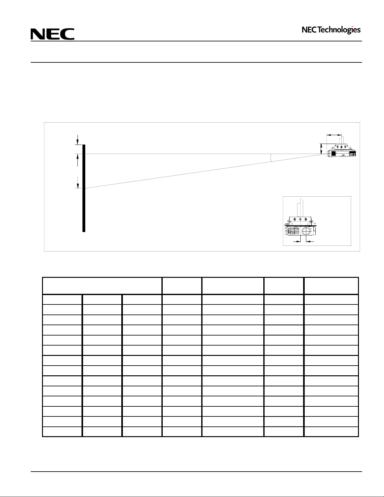
Projection Distance and Screen Size for Ceiling Mount
The following shows the proper relative positions of the projector and screen. Refer to the table to determine the position of
installation.
Distances are in inches. For millimeters multiply by 25.4.
Ceiling Mount Installation
5.7"
Screen Top
Lens Ctr
Screen Ctr
D
B
C
Throw Distance
α
Distance Chart
Screen Size
Diagonal Width Height wide - tele wide - tele
40" 32" 24" 10" 62" - 72" 2" 8.8° - 7.7°
60" 48" 36" 14" 94" - 109" 4" 8.7° - 7.6°
67" 53.6" 40.2" 16" 106" - 122" 4" 8.6° - 7.6°
72" 57.6" 43.2" 17" 114" - 131" 4" 8.6° - 7.5°
84" 67.2" 50.4" 20" 133" - 153" 5" 8.6° - 7.5°
90" 72" 54" 22" 143" - 164" 5" 8.6° - 7.5°
100" 80" 60" 24" 159" - 183" 6" 8.6° - 7.5°
120" 96" 72" 29" 191" - 220" 7" 8.6° - 7.5°
150" 120" 90" 36" 239" - 275" 9" 8.6° - 7.5°
180" 144" 108" 43" 288" - 331" 11" 8.6° - 7.5°
210" 168" 126" 51" 336" - 386" 12" 8.6° - 7.5°
240" 192" 144" 58" 384" - 442" 14" 8.6° - 7.4°
270" 216" 162" 65" 432" - ---- 16" 8.5° - ---
300" 240" 180" 72" 481" - ---- 18" 8.5° - ---
BCD
Note:
For screen sizes of 25 to 300 inches not indicated on the projection tables, use the formulas on page 1.
4.2"
Lens Offset from
Mounting Pipe
1.6"
αααα
Page 2
Page 3
Visual Systems
LT154/155/156 Installation Data
Desktop and Ceiling Mount Rev. 1.8
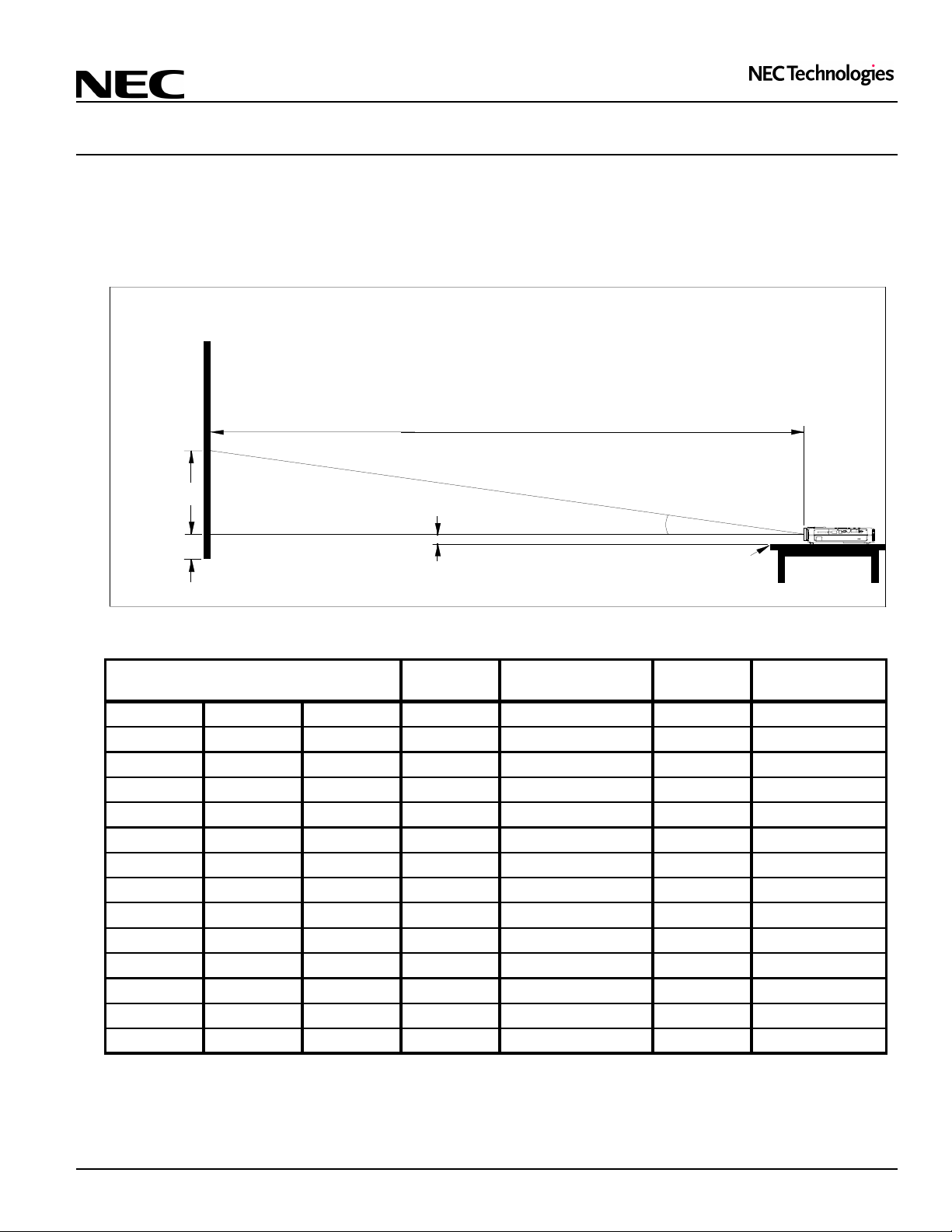
Projection Distance and Screen Size for Desktop
The following diagram shows the relationship between projector position and the screen.
Distances are in inches. For millimeters multiply by 25.4.
Desktop Setup
C
Screen Ctr
B
Throw Distance
Lens Ctr
D
Screen Bottom
1.6"
α
Projector Foot
Distance Chart
Screen Size
Diagonal Width Height wide - tele wide - tele
40" 32" 24" 10" 62" - 72" 2" 8.8° - 7.7°
60" 48" 36" 14" 94" - 109" 4" 8.7° - 7.6°
67" 53.6" 40.2" 16" 106" - 122" 4" 8.6° - 7.6°
72" 57.6" 43.2" 17" 114" - 131" 4" 8.6° - 7.5°
84" 67.2" 50.4" 20" 133" - 153" 5" 8.6° - 7.5°
90" 72" 54" 22" 143" - 164" 5" 8.6° - 7.5°
100" 80" 60" 24" 159" - 183" 6" 8.6° - 7.5°
120" 96" 72" 29" 191" - 220" 7" 8.6° - 7.5°
150" 120" 90" 36" 239" - 275" 9" 8.6° - 7.5°
180" 144" 108" 43" 288" - 331" 11" 8.6° - 7.5°
210" 168" 126" 51" 336" - 386" 12" 8.6° - 7.5°
240" 192" 144" 58" 384" - 442" 14" 8.6° - 7.4°
270" 216" 162" 65" 432" - ---- 16" 8.5° - ---
300" 240" 180" 72" 481" - ---- 18" 8.5° - ---
BCD
Note:
For screen sizes of 25 to 300 inches not indicated on the projection tables, use the formulas on page 1.
αααα
Page 3
Page 4

Visual Systems
LT154/155/156 Installation Data
Desktop and Ceiling Mount Rev. 1.8
Cabinet Dimensions
The following diagrams show the cabinet dimensions for the LT154/155/156.
Dimensions are in inches. For millimeters multiply by 25.4.
R
1
.
1
0
0
1
.
1
R
7
4
.
0
1
0
1
.
1
R
9
6
6
.
0
R
1
.
1
0
0.197
1.59
2.49
8.15
Page 4
Page 5

Visual Systems
LT154/155/156 Installation Data
Desktop and Ceiling Mount Rev. 1.8
Cabinet Dimensions (continued)
The following diagrams show the cabinet dimensions for the LT154/155/156.
Dimensions are in inches. For millimeters multiply by 25.4.
4.83
4.09
5
4
9
.
0
2.99
9
8
6
.
0
6
8
.
9
R 5.20
M4*8
3.44
4.07
M4*8
2.76
Ø 2.17
3.44
M4*8
1
5
5
.
0
4
6
.
7
9
4
.
4
R 5.20
3
8
.
4
7
0
.
9
0.14
8
6
.
2
R 5.20
4.06
0.098
Page 5
Page 6

Visual Systems
LT154/155/156 Installation Data
Desktop and Ceiling Mount Rev. 1.8
Ceiling Mount Dimensions (Model #: LT55CM)
The following diagrams show ceiling mount dimensions for the LT154/155/156.
Dimensions are in inches. For millimeters multiply by 25.4.
8.6500
5.2726
9.2726
1.9000
Ø
Front
4.3250
2.8050
2.6900
2.8050
Page 6
Page 7

Visual Systems
LT154/155/156 Installation Data
Desktop and Ceiling Mount Rev. 1.8
Ceiling Mount Dimensions (Model #: LT55CM) (continued)
The following diagrams show ceiling mount dimensions for the LT154/155/156.
Dimensions are in inches. For millimeters multiply by 25.4.
9.2726
Front
8.6500
2.8050
Page 7
Page 8

Visual Systems
LT154/155/156 Installation Data
Desktop and Ceiling Mount Rev. 1.8
PC Control Codes
Function Code Data
POWER ON 02H 00H 00H 00H 00H 02H
POWER OFF 02H 01H 00H 00H 00H 03H
INPUT SELECT DVI (Digital) 02H 03H 00H 00H 02H 01H 1AH 22H
INPUT SELECT RGB 02H 03H 00H 00H 02H 01H 01H 09H
INPUT SELECT VIDEO 02H 03H 00H 00H 02H 01H 06H 0EH
INPUT SELECT S-VIDEO 02H 03H 00H 00H 02H 01H 0BH 13H
INPUT SELECT PC CARD VIEW ER 02H 03H 00H 00H 02H 01H 1FH 27H
PICTURE MUTE ON 02H 10H 00H 00H 00H 12H
PICTURE MUTE OFF 02H 11H 00H 00H 00H 13H
SOUND MUTE ON 02H 12H 00H 00H 00H 14H
SOUND MUTE OFF 02H 13H 00H 00H 00H 15H
ON SCREEN MUTE ON 02H 14H 00H 00H 00H 16H
ON SCREEN MUTE OFF 02H 15H 00H 00H 00H 17H
Cable Connection
Communication Protocol:
Baud Rate: 38400 bps
Data Length: 8 bits
Parity: No Parity
Stop Bit: One bit
X on/off: None
Communications: Full duplex
PC Control Connector (DIN-8P)
(LT156 ONLY)
(DVI Analog for LT156)
To RxD of PC
678
345
12
To GND of PC
NOTE 1: Pins 2, 3, 5, 6 and 8 are used inside the projector.
NOTE 2: For long cable runs it is recommended to set communication speed within projector menus to 9600 bps.
To TxD of PC
Page 8
 Loading...