

NEC LD79A02K Datasheet
DATA SHEET
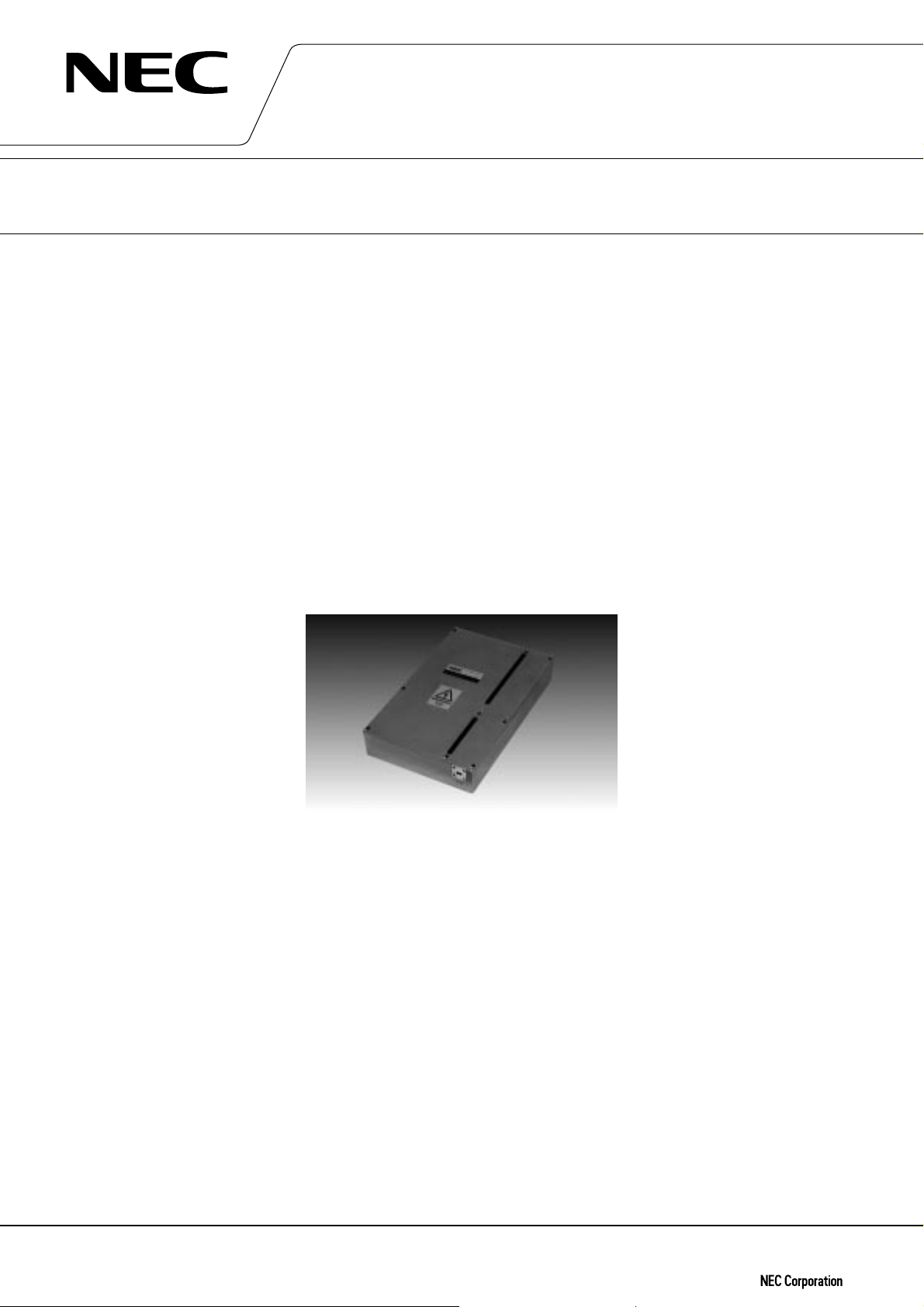
MICROWAVE POWER MODULE
FOR COMMUNICATIONS
LD79A02K
30 GHz, 20 W CW, LIGHT WEIGHT, COMPACT, EFFICIENT
GENERAL DESCRIPTION
MPM stands for Microwave Power Module and is the solution introduced by NEC for a microwave power
source with high efficiency and the most compact size.
The MPM consists of a miniaturized traveling wave tube (TWT) and an electronic power conditioner (EPC). All
the potential interface problems are taken care of by NEC and the user simply connects the MPM to his RF
output and plugs in the DC supply.
LD79A02K is a complete integrated unit and can deliver an output power of 20 W over the range of 27.5 to
30.0 GHz with a gain of 40 dB.
The TWT of RF section in the LD79A02K has been designed and developed upon the NEC's advanced technology
and enormous experience on a number of TWTs used in satellite ground terminals and terrestrial microwave
links.
The very small and light weight EPC designed with sophisticated and experienced circuit technology ensures
higher reliability, reduced maintenance costs and improved technical performance.
The LD79A02K is most suitable for a power amplifier in LMDS and Multimedia Satellite communication
systems.
FEATURES
™ Light weight, Compact, and Efficient
The TWT built in the MPM has a dual-depressed collector and is designed to operate at high efficiency across
the power output range. The EPC features state-of-the-art techniques to optimize size and efficiency and the
combination results in a unit significantly smaller and with less power consumption than a comparable solid
state amplifier.
™ Low Distortion
NEC has developed techniques for the correction of non-linear distortion of gain and phase generated in a
TWT. As a result, the MPM has optimum performance across a broad power range and is ideally suited for
multi-carrier transmission systems.
™ Long Life
The TWT is designed to have a lifetime of 80,000 hours or more, which is comparable to that of a solid state
amplifier in actual usage.
™ Ideal for Digital Systems
A mini-arcing in the electron gun have been eliminated in the TWT.
The information in this document is subject to change without notice.
Document No. ET0361EJ1V1DS00
Date Published September 1998 M
Printed in Japan
©
1998

TYPICAL OPERATIONS
Frequency Range ………………………………………… 27.5–30.0 GHz
Power Output …………………………………………… 20 W minimum
Gain Variation …………………………………………… 2.5 dB / 2.5 GHz
Gain ……………………………………………………… 43 dB (at Po = 20 W)
50 dB (at small signal)
Gain Stability …………………………………………… ±0.25 dB/24 hr (25˚C±10˚C)
Gain Slope ………………………………………………… 0.02 dB / MHz
Harmonic Output ………………………………………… 15 dB below at rated output power
Spurious Output …………………………………………–70 dBW in any 4 kHz band
in the 27.5 to 30.0 GHz
AM to PM Conversion …………………………………4°/ dB at rated power
Intermodulation ………………………………………… 30 dB below each of two equal carriers
(total 2 W)
Group Delay
Linear component …………………………………… 0.1 ns / MHz
Parabolic component………………………………… 0.01 ns / MHz
Ripple component ……………………………………1.0 ns (p-p) in any 40 MHz band
RF Input
Waveguide …………………………………………… Mates with UG-599 / U Flange
VSWR …………………………………………………… 2.0 : 1 maximum
Load VSWR …………………………………………… Operate into 1.5 : 1 maximum
RF Output
Waveguide …………………………………………… Mates with UG-599 / U Flange
VSWR …………………………………………………… 2.0 : 1 maximum
Load VSWR …………………………………………… Operate into 1.5 : 1 maximum
Primary Power …………………………………………… –48 V ± 10%
Power Consumption …………………………………… 86 W
Efficiency ………………………………………………… 25% approx.
Dimensions ……………………………………………… 240 × 150 × 40 mm
Weight ……………………………………………………… 2.1 kg approx.
2
LD79A02K
ENVIRONMENTAL CONDITIONS
™ Ambient Temperature
–30°C to +70°C (non operating, storage)
™ Relative Humidity
90% maximum (non dewing)
™ Base Plate Temperature
–15°C to +65°C maximum
Note 1 : These characteristics and operating values may be changed as a result of additional information or
product improvement. NEC should be consulted before using this information for equipment design. This data sheet should not be referred to a contractual specification.
2
 Loading...