


Index
Important Information .......................................................................................................................... English-2
Safety Precautions, Maintenance, & Recommended Use................................................................ English-3
Contents .................................................................................................................................................... English-4
Attaching LCD Options ............................................................................................................................ English-5
Parts Name and Functions
Control Panel ............................................................................................................................ English-6
Terminal Panel .......................................................................................................................... English-7
Wireless Remote Control ........................................................................................................ English-8
Operating Range for the Remote Control .......................................................................... English-9
Handling the Remote Control ............................................................................................... English-9
Setup Procedure ...................................................................................................................................... English-10
Connections
Wiring Diagram..................................................................................................................... English-12
Connecting the LCD Monitor to a PC ............................................................................... English-13
Connecting to a Macintosh Computer............................................................................. English-14
Connecting to a Computer with a Digital Output ......................................................... English-15
Connecting to a DVD Player ............................................................................................... English-16
Connecting to a Stereo Amplifier .................................................................................... English-17
Basic Operation
Power On and Off modes ......................................................................................................... English-18
Power Indicator........................................................................................................................ English-19
When Using Power Management Function.......................................................................... English-19
Selecting a Video Source ........................................................................................................ English-19
Picture Size ............................................................................................................................... English-19
Picture Mode ............................................................................................................................. English-19
OSM Information ...................................................................................................................... English-19
OSM (On-Screen-Manager) Controls ................................................................................................... English-20
Picture ........................................................................................................................................ English-20
Screen......................................................................................................................................... English-21
Audio ........................................................................................................................................... English-22
Configuration 1 ......................................................................................................................... English-23
Configuration 2 ........................................................................................................................ English-24
Advanced Option ...................................................................................................................... English-26
NOTE ............................................................................................................................................ English-28
Using the LCD with a Personal Computer (PC) .................................................................................. English-29
Features ..................................................................................................................................................... English-32
Troubleshooting ....................................................................................................................................... English-33
References ................................................................................................................................................ English-34
Specifications ........................................................................................................................................... English-35
Pin Assignment ......................................................................................................................................... English-37
Limited Warranty..................................................................................................................................... English-38
English
English-1
Important Information
WARNING
TO PREVENT FIRE OR SHOCK HAZARDS, DO NOT EXPOSE THIS UNIT TO RAIN OR MOISTURE. ALSO, DO NOT USE THIS UNIT'S
POLARIZED PLUG WITH AN EXTENSION CORD RECEPTACLE OR OTHER OUTLETS UNLESS THE PRONGS CAN BE FULLY INSERTED.
REFRAIN FROM OPENING THE CABINET AS THERE ARE HIGH VOLTAGE COMPONENTS INSIDE. REFER SERVICING TO QUALIFIED
SERVICE PERSONNEL.
CAUTION
CAUTION: TO REDUCE THE RISK OF ELECTRIC SHOCK, MAKE SURE POWER CORD IS UNPLUGGED FROM WALL SOCKET. TO FULLY
DISENGAGE THE POWER TO THE UNIT, PLEASE DISCONNECT THE POWER CORD FROM THE AC OUTLET. DO NOT REMOVE
COVER (OR BACK). NO USER SERVICEABLE PARTS INSIDE. REFER SERVICING TO QUALIFIED SERVICE PERSONNEL.
This symbol warns user that uninsulated voltage within the unit may have sufficient magnitude to cause electric shock. Therefore, it is
dangerous to make any kind of contact with any part inside this unit.
This symbol alerts the user that important literature concerning the operation and maintenance of this unit has been included. Therefore,
it should be read carefully in order to avoid any problems.
Canadian Department of Communications Compliance Statement
DOC: This Class B digital apparatus meets all requirements of the Canadian Interference-Causing Equipment Regulations.
C-UL: Bears the C-UL Mark and is in compliance with Canadian Safety Regulations according to
CAN/CSA C22.2 No.
60950-1.
FCC Information
1.
Use the attached specified cables with the MultiSync® LCD4010™ (L404G6)
as not to interfere with radio and television reception.
(1)
Please use the supplied power cord or equivalent to ensure FCC compliance.
(2) Please use the supplied shielded video signal cable, 15-pin mini D-SUB to 15-pin mini D-SUB.
(3) Please attach the ferrite cores on the Audio Cable. Please see page 12 of this manual.
2.
This equipment has been tested and found to comply with the limits for a Class B digital device, pursuant to part 15 of the FCC
Rules. These limits are designed to provide reasonable protection against harmful interference in a residential installation. This
equipment generates, uses, and can radiate radio frequency energy, and, if not installed and used in accordance with the
instructions, may cause harmful interference to radio communications. However, there is no guarantee that interference will
not occur in a particular installation. If this equipment does cause harmful interference to radio or television reception, which
can be determined by turning the equipment off and on, the user is encouraged to try to correct the interference by one or more
of the following measures:
• Reorient or relocate the receiving antenna.
• Increase the separation between the equipment and receiver.
• Connect the equipment into an outlet on a circuit different from that to which the receiver is connected.
• Consult your dealer or an experienced radio/TV technician for help.
/ MultiSync LCD4610 (L464G7)
color monitor so
If necessary, the user should contact the dealer or an experienced radio/television technician for additional suggestions. The
user may find the following booklet, prepared by the Federal Communications Commission, helpful: ”How to Identify and Resolve
Radio-TV Interference Problems.“ This booklet is available from the U.S. Government Printing Office, Washington, D.C., 20402,
Stock No. 004-000-00345-4.
English-2

Safety Precautions, Maintenance & Recommended Use
Safety Precautions and Maintenance
FOR OPTIMUM PERFORMANCE, PLEASE NOTE THE FOLLOWING
WHEN SETTING UP AND USING THE MultiSync
MultiSync
• DO NOT OPEN THE MONITOR. There are no user serviceable
• Do not spill any liquids into the cabinet or use your monitor
• Do not insert objects of any kind into the cabinet slots, as they
• Do not place any heavy objects on the power cord. Damage to
• Do not place this product on a sloping or unstable cart, stand or
• When operating the MultiSync LCD4010 / MultiSync LCD4610
• In the UK, use a BS-approved power cord with molded plug
• Do not place any objects onto the monitor and do not use the
• The inside of the fluorescent tube located within the LCD
• Do not bend, crimp or otherwise damage the power cord.
• Do not use monitor in high temperature, humid, dusty, or oily
• If glass is broken, handle with care.
• Do not cover vent on monitor.
• If monitor or glass is broken, do not come in contact with the
• Allow adequate ventilation around the monitor so that heat can
• The power cable connector is the primary means of detaching
• Handle with care when transporting. Save packaging for
• Keep the vent holes on the back of the LCD clean of dirt and
• If using the cooling fan continuously, it’s recommended to wipe
®
LCD 4610LCD COLOR MONITOR:
parts inside and opening or removing covers may expose you
to dangerous shock hazards or other risks. Refer all servicing to
qualified service personnel.
near water.
may touch dangerous voltage points, which can be harmful or
fatal or may cause electric shock, fire or equipment failure.
the cord may cause shock or fire.
table, as the monitor may fall, causing serious damage to the
monitor.
monitor with its AC 125-240V power supply, use a power supply cord that matches the power supply voltage of the AC power
outlet being used. The power supply cord you use must have
been approved by and comply with the safety standards of your
country. (Type H05VV-F 3G 1mm
having a black (13A) fuse installed for use with this monitor. If a
power cord is not supplied with this monitor, please contact your
supplier.
monitor outdoors.
monitor contains mercury. Please follow the bylaws or rules of
your municipality to dispose of the tube properly.
areas.
liquid crystal. Handle broken glass with care.
properly dissipate. Do not block ventilated openings or place
the monitor near a radiator or other heat sources. Do not put
anything on top of monitor.
the system from the power supply. The monitor should be installed close to a power outlet which is easily accessible.
transporting.
dust. It is recommended to wipe holes with a soft cloth a
minimum of once per year.
vent holes a minimum of once a month
2
should be used in Europe)
®
LCD4010™ /
CAUTION
Immediately unplug your monitor from the wall outlet and refer
servicing to qualified service personnel under the following
conditions:
• When the power supply cord or plug is damaged.
• If liquid has been spilled, or objects have fallen into the
monitor.
• If the monitor has been exposed to rain or water.
• If the monitor has been dropped or the cabinet damaged.
• If the monitor does not operate normally by following operating
instructions.
Recommended Use
CAUTION
CORRECT PLACEMENT AND ADJUSTMENT OF THE MONITOR
CAN REDUCE EYE, SHOULDER AND NECK FATIGUE. CHECK THE
FOLLOWING WHEN YOU POSITION THE MONITOR:
• For optimum performance, allow 20 minutes for warm-up.
• Rest your eyes periodically by focusing on an object at least 5
feet away. Blink often.
• Position the monitor at a 90˚ angle to windows and other light
sources to minimize glare and reflections.
• Clean the LCD monitor surface with a lint-free, nonabrasive cloth.
Avoid using any cleaning solution or glass cleaner.
• Adjust the monitor’s brightness and contrast controls to enhance
readability.
•Avoid displaying fixed patterns on the monitor for long periods
of time to avoid image persistence (afterimage effects).
• Get regular eye checkups.
• The backlight lamp contains mercury. Please handle it appropriately in case of disposal.
Ergonomics
To realize the maximum ergonomic benefits, we recommend the
following:
• Use the preset Size and Position controls with standard
signals.
• Use the preset Color Setting.
• Use non-interlaced signals.
• Do not use primary color blue on a dark background, as it is
difficult to see and may produce eye fatigue due to insufficient
contrast.
For more detailed information on setting up a healthy work
environment, write the American National Standard for Human Factors Engineering of Visual Display Terminal Workstations – ANSIHFS Standard No. 100-1988 – The Human Factors Society, Inc.
P.O. Box 1369, Santa Monica, California 90406.
English
English-3
Contents
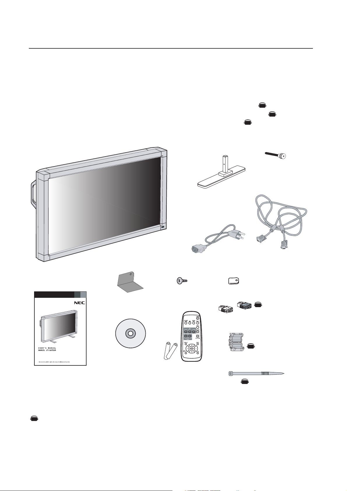
Your new MultiSync® LCD4010™ / MultiSync® LCD4610™ monitor box* should contain the
following:
• LCD monitor
• Power Cord (3m)
• Video Signal Cable – SC-B113 (4m)
• User’s Manual
• Wireless Remote Control and AA Batteries
• Clamper x 3
• Screw (M4 x 8) x 4
• CD-ROM
• Stand x 2
• Thumbscrew for stand x 2
• Main switch cover x 1
• Ferrite Core x 2
• Speaker Plug x 1 set
• Band x 2
Stand x 2
AV
AV
AV
Thumbscrew
for stand x 2
Power Cord
Screw (M4 x 8 ) x 4
Main switch cover x 1
MultiSync® LCD4010™
®
MultiSync
LCD4610™
User’s Manual
CD-ROM
Wireless Remote Control
and AA Batteries
*Install at the time of unpacking if the display will be used with the stand.
*Remember to save your original box and packing material to transport or ship the monitor.
NOTE: The AV Unit is installed only on the LCD4010-BK(A)/LCD4610-BK(A).
AV
Denotes an AV unit function.
All AV functions are enabled when the AV unit is installed.
Video Signal Cable
(D-SUB to D-SUB Cable)
Clamper x 3
Speaker Plug x 1 set
AV
(Attached to external
speaker terminal)
Ferrite Core
AV
AV
Band
x 2
x 2
The following optional components are available to use with the MultiSync LCD4010 / MultiSync LCD4610. To obtain the
optional components and additional information, contact Customer Service at (800) 632-4662.
• Macintosh Cable Adapter
• External Speakers
English-4
Screw Holes
Clamper
Cord or Chain
Screw
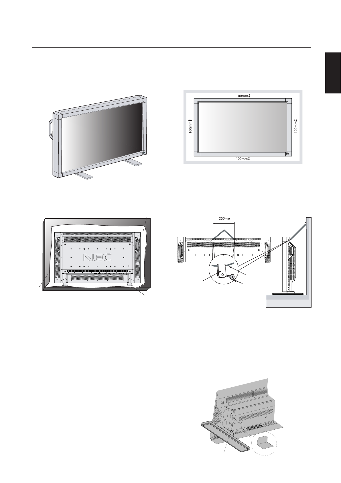
Attaching LCD Options
You can attach mounting accessories to the LCD monitor in one of
the following two ways:
1. In the upright position
2. Lay the screen face down
Protective Sheet
3. Ventilation Requirements for enclosure
mounting
To allow heat to disperse, leave space between surrounding
objects as shown in the diagram below.
4. To prevent the LCD Monitor from
falling down
Fasten the LCD monitor to a wall using a cord or chain which is
sufficient to support the weight of the LCD monitor (approx. 27.5kg
for the LCD4010 and approx. 32.8kg for the LCD4610).
Before moving the LCD monitor, the cord or chain should be removed.
English
Tab le
Tab letop Stand
To avoid damaging the screen face, place the protective sheet on
the table underneath the LCD. The protective sheet was wrapped
around the LCD in the original packaging. Make sure there is nothing on the table that can damage the monitor.
This device cannot be used or installed without the Tabletop Stand
or other mounting accessory. For proper installation it is strongly
recommended to use a trained, NEC authorized service person.
Failure to follow NEC standard mounting procedures could result in
damage to the equipment or injury to the user or installer. Product
warranty does not cover damage caused by improper installation.
Failure to follow these recommendations could result in voiding your
warranty.
When using mounting accessories other than NEC compliant and
approved, they must comply with the VESA-compatible mounting
method. NEC strongly recommends using screws M6 size and
10mm in length. If using screws longer than 10mm, check the depth
of the hole. (Recommended Fasten Force: 470-635N•cm)
NEC recommends using mounting interface that comply with UL1678
standard in North America.
5. To prevent use of Main Power Switch
To prevent the use of the Main Power Switch, if desired, please attach the Main Power Switch cover which is included as an accessory.
NOTE: With the main power switch cover in place, the main power
switch can not be turned off. To turn the power off, remove the
main power switch cover and turn off the switch, or remove the
power cord from the AC Inlet at the back of the monitor.
Screw
English-5
Main switch cover
Parts Name and Functions
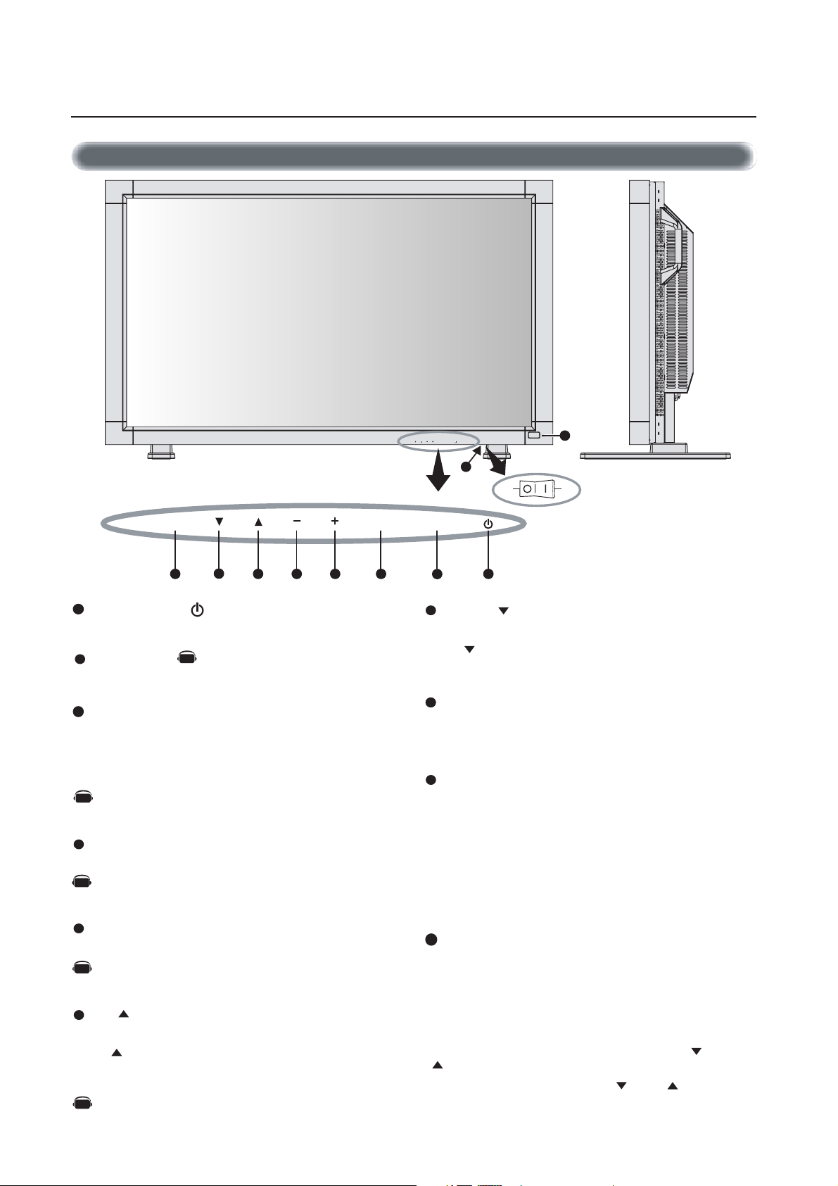
Control Panel
EXIT MUTEINPUT
5
67
1
POWER button ( )
8 1234
Switches the power on/off. See page 18.
2
MUTE button
AV
Switches the audio mute ON/OFF.
3
INPUT button
Acts as SET button within the OSM menu.
Selects which signal connected to the display is shown. (Toggle
switches between [RGB1], [RGB2], [RGB3], [DVD/HD], or
[VIDEO].)
[DVD/HD] and [VIDEO] inputs are enabled when the AV-unit
AV
option is installed.
4
PLUS (+) button
Acts as (+) button to increase the adjustment with OSM menu.
AV
Increases the audio output level when the OSM menu is turned
off.
5
MINUS (-) button
Acts as (-) button to decrease the adjustment with OSM menu.
AV
Decreases the audio output level when the OSM menu is turned
off.
6
UP ( ) button
Activates the OSM menu when the OSM menu is turned-off.
Acts as button to move the highlighted area up to select the
adjustment with OSM menu.
Denotes an AV unit function.
AV
All AV functions are enabled when the AV unit is installed.
EXIT MUTEINPUT
10
9
ONOFF
Button Location
7
DOWN ( ) button
Activates the OSM menu when the OSM menu is turned-off.
Acts as button to move the highlighted area down to select the
adjustment with OSM menu.
8
EXIT button
Activates the OSM menu when the OSM menu is turned-off.
Acts as EXIT button to move to previous menu in the OSM menu.
9
Remote control sensor and Power indicator
Receives the signal from the remote control (when using the
wireless remote control). See page 9.
Glows green when the LCD monitor is in active mode and glows
red when the LCD is in POWER OFF mode. When the LCD is in
power save mode, it will glow both green and red. When
SCHEDULE is enabled, it will blink green. See page 19.
When a component failure is detected within the monitor, it will
blink red.
10
Main Power Switch
Seesaw Switch for the main power on/off.
Control Key Lock Mode
This control completely locks out access to all Control Key
functions.
To activate the control key lock function, press both “ “ and
“ “ simultaneously and hold down for three (3) seconds.
To go back to user mode, press both “ “ and “ “ simultaneously and hold for three (3) seconds.
English-6
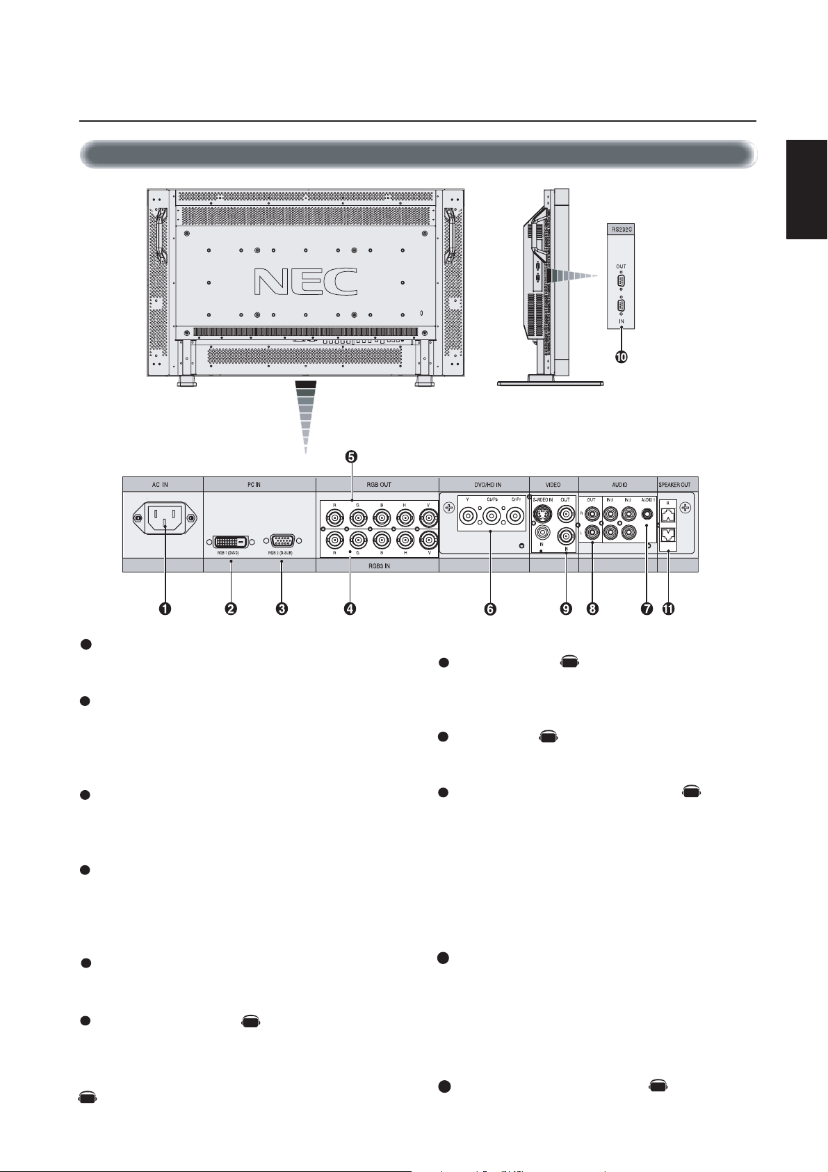
Parts Name and Functions –continued
Terminal Panel
English
1
AC IN connector
Connects with the supplied power cord.
2
RGB 1 IN (DVI-D)
To input digital RGB signals from a computer or HDTV device
having a digital RGB output.
* This connector does not support analog input.
3
RGB 2 IN (mini D-Sub 15 pin)
To input analog RGB signals from a personal computer or other
RGB equipment.
4
RGB 3 [R, G, B, H, V] (BNC)
IN connector:
other RGB equipment. A Sync-on-Green signal can be connected to the G connector.
5
RGB OUT connector (BNC)
To output the signal from the RGB 3 IN connector.
6
DVD/HD connector (BNC)
Connecting equipment such as a DVD player, HDTV device, or
Laser disc player.
To input the analog RGB signals or signals from
AV
7
AUDIO IN 1,2,3
Input audio signal from external equipment such as a computer,
VCR or DVD player.
8
AUDIO OUT
Output the audio signal from the selected AUDIO IN source.
9
VIDEO INPUT/OUTPUT CONNECTOR
VIDEO IN connector (BNC and RCA): Input a composite video
signal. BNC and RCA are not available at the same time.
(Use only one input).
VIDEO OUT connector (BNC): Output the composite video
signal from the VIDEO IN source.
S-VIDEO IN connector (DIN 4 pin): Input the S-video (Y/C
separate signal). See page 26, S-VIDEO MODE SETTING.
EXTERNAL CONTROL (mini D-Sub 9 pin) RS-232C
10
In connector: Input signal from control equipment such as a
computer or the output from a different MultiSync LCD4010 /
MultiSync LCD4610.
Out connector: To connect multiple MultiSync LCD4010
AV
AV
AV
/
MultiSync LCD4610
Denotes an AV unit function.
AV
All AV functions are enabled when the AV unit is installed.
EXTERNAL SPEAKER TERMINAL
11
Outputs the audio signal from the selected audio source.
English-7
AV
Parts Name and Functions –continued
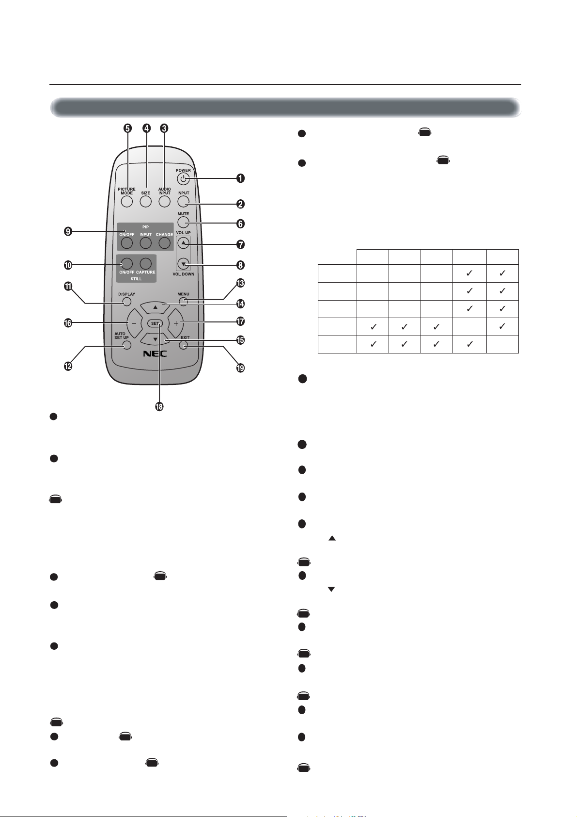
Wireless Remote Control
REMOTE
1
POWER button
CONTROLLER RU-M104
Switches the power on/off.
* If Power Indicator is not glowing, then no controls will work.
2
INPUT button
Selects from input signal, [RGB1], [RGB2], [RGB3], [DVD/HD],
[VIDEO] and [VIDEO<S>].
AV
[DVD/HD], [VIDEO] and [VIDEO<S>] inputs can be selected
when the AV optional module is installed.
[VIDEO<S>] is enabled by selecting the “SEPARATE” mode
in the OSM or by having the “S VIDEO” cable connected
with the “S VIDEO” signal present and selecting “PRIORITY”
MODE”. See page 26.
3
AUDIO INPUT button
AV
Selects from input audio signal, [AUDIO1], [AUDIO2], [AUDIO3]
4
SIZE button
Selects picture size, [FULL], [NORMAL], [WIDE] and [ZOOM].
See page 19.
5
PICTURE MODE button
Selects from picture mode, [HIGHBRIGHT], [STANDARD],
[sRGB], [CINEMA]. See page 19.
HIGHBRIGHT: for moving image such as DVD
STANDARD: for images
sRGB: for text based images
AV
CINEMA: for movies.
6
MUTE button
AV
To turn on/off the mute function.
7
VOLUME UP button
AV
Increase the audio output level.
8
VOLUME DOWN button
AV
Decrease the audio output level.
9
PIP (Picture In Picture) button
ON/OFF button: Toggle switches between PIP,POP, side-by-side
(aspect) and side-by-side (full).
INPUT button: Select the ‘picture in picture’ input signal.
CHANGE button: Replaces to the main picture and sub
picture.
Sub Picture
RGB2RGB1
1BGR
2BGR
3BGR
Main Picture
OEDIV
Note: The aspect ratio of PIP synchronizes with a setup in the Main Picture.
10
STILL button
___
___
___
DH/DVD
RGB3 DVD/HD VIDEO
ON/OFF button: To turn on/off the still picture mode.
CAPTURE button: Capture the new picture.
Note: Will not work when pixel clock is greater than 108MHz
11
DISPLAY button
To turn on/off the Information OSM. See page 19.
12
AUTO SETUP button
To enter the auto setup menu. See page 23.
13
MENU button
To turn on/off the menu mode.
14
UP button
Acts as button to move the highlighted area up to select the
adjustment with OSM menu.
AV
Small screen which adjusted “PIP” mode moves up.
15
DOWN button
Acts as button to move the highlighted area down to select
the adjustment with OSM menu.
AV
Small screen which adjusted “PIP” mode moves down.
16
MINUS button decrease
Acts as (-) button to decrease the adjustment with OSM menu.
AV
Small screen which adjusted “PIP” mode moves left.
17
PLUS button increase
Acts as (+) button to increase the adjustment with OSM menu.
AV
Small screen which adjusted “PIP” mode moves right.
18
SET button
Acts as SET button with OSM menu.
19
EXIT button
Turn to previous menu with OSM menu.
Denotes an AV unit function.
AV
All AV functions are enabled when the AV unit is installed.
English-8
AV
_
_
Parts Name and Functions –continued
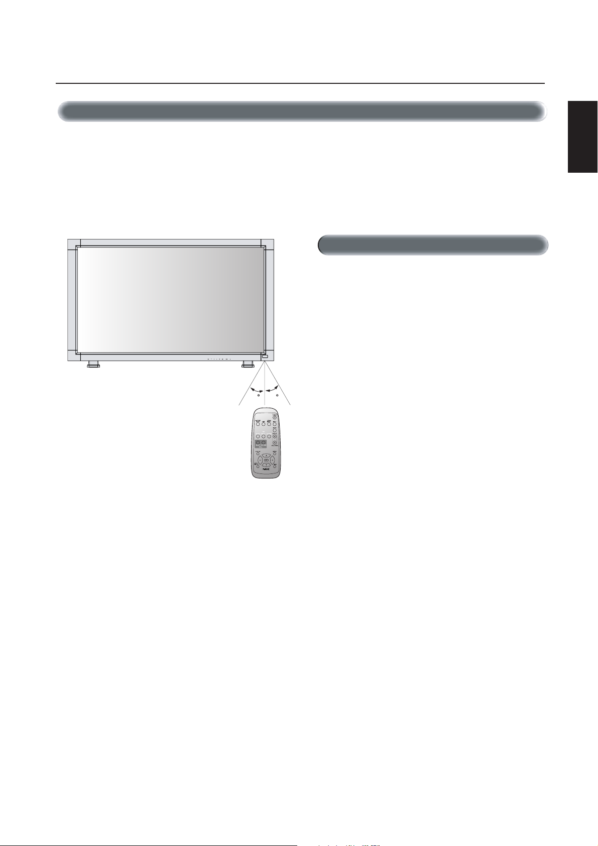
Operating Range for the Remote Control
Point the top of the remote control toward the LCD monitor's remote
sensor while pressing button.
Use the remote control within a distance of about 7 m/23 ft. from
the front of the LCD monitor's remote control sensor and at a horizontal and vertical angle of within 30 degree within a distance of
about 3 m/10 ft.
30 30
Caution
The remote control system may not function when direct sunlight or
strong illumination strikes the remote control sensor of the LCD monitor, or when there is an object in the path.
Handling the remote control
*Do not open the remote control other than to install batteries.
*
Do not allow water or other liquid to splash onto the remote
control. If the remote control gets wet, wipe it dry immediately.
*Avoid exposure to heat and steam.
English
REMOTE
CONTROLLER RU-M104
English-9
Setup Procedure
AV
1. Determine the installation location
CAUTION
Installing your LCD display must be done by a qualified technician.
Contact your dealer for more information.
CAUTION
MOVING OR INSTALLING THE LCD MONITOR MUST BE DONE
BY TWO OR MORE PEOPLE. Failure to follow this caution may
result in injury if the LCD monitor falls.
CAUTION
Do not mount or operate the display upside down, face up, or face down.
CAUTION
This LCD has a temperature sensor and cooling fan. If the LCD becomes too hot, the cooling fan will turn on automatically. If the LCD
becomes overheated while the cooling fan is running, the “Caution”
menu will appear. If the “Caution” menu appears, discontinue use
and allow the unit to cool. Using the cooling fan will reduce the
likelihood of “Image Persistence”.
If the LCD is used in an enclosed area or if the LCD panel is covered
with a protective screen, please check the inside temperature of the
monitor by using the “HEAT STATUS” control in the OSM (see page
27). If the temperature is higher than the normal operating temperature, please turn the cooling fan to ON within the SCREEN SAVER
menu within the OSM (see page 24).
IMPORTANT
Lay the protective sheet, which was wrapped around the LCD monitor
when it was packaged, beneath the LCD monitor so as not to scratch
the panel.
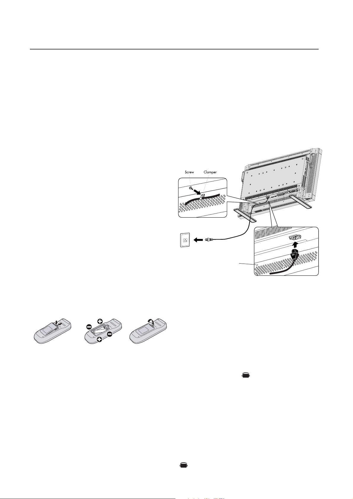
2. Install the remote control batteries
The remote control is powered by 1.5V AA batteries. To install or
replace batteries:
1. Press and slide to open the cover.
2. Align the batteries according to the (+) and (–) indications inside the case.
3. Replace the cover.
4. Connect the supplied power cord
• The equipment should be installed close to an easily accessible
power outlet.
• Please attach power cord to the LCD monitor by attaching the
screw and clamper.
• Fully insert the prongs into the power outlet socket. Loose connection may cause image degradation.
NOTE: If you use this monitor at AC 220 - 240V, please refer
to “safety Precautions, Maintenance & recommended Use”
section of this manual for proper selection of AC power cord.
Screwhole for clamper
5. Switch on the power of all the attached
external equipment
When connected with a computer, switch on the power of the computer first.
CAUTION
Incorrect usage of batteries can result in leaks or bursting. NEC
recommends the following battery use:
• Place "AA" size batteries matching the + and - signs on each
battery to the + and - signs of the battery compartment.
• Do not mix battery brands.
• Do not combine new and old batteries. This can shorten battery
life or cause liquid leakage of batteries.
• Remove dead batteries immediately to prevent battery acid from
leaking into the battery compartment. Don't touch exposed battery acid, it can damage to your skin.
NOTE: If you do not intend to use the Remote Control for a
long period of time, remove the batteries.
6. Operate the attached external equipment
Display the signal from the desired input source.
7. Adjust the sound
Make volume adjustments as required.
AV
8. Adjust the screen (See pages 20-28)
Make adjustments of the screen display position when necessary.
9. Adjust the image (See pages 20-28)
Make adjustments such as brightness or contrast when required.
3. Connect external equipment (See pages 12-17)
•To protect the external equipment, turn off the main power before making connections.
• Refer to your equipment user manual for further information.
English-10
Denotes an AV unit function.
All AV functions are enabled when the AV unit is installed.
Setup Procedure –continued
10. Recommended Adjustments
To reduce the risk of the “image persistence”, please adjust the following items based on the application being used.
“SCREEN SAVER” (See page 24), see page ”SIDE BORDER COLOR”
(See page 24), “DATE & TIME” (See page 27), “SCHEDULE” (See
page 27)
11. When the monitor is installed in the portrait position
• Remove the stands (feet).
• Left edge should be the upper edge from front view.
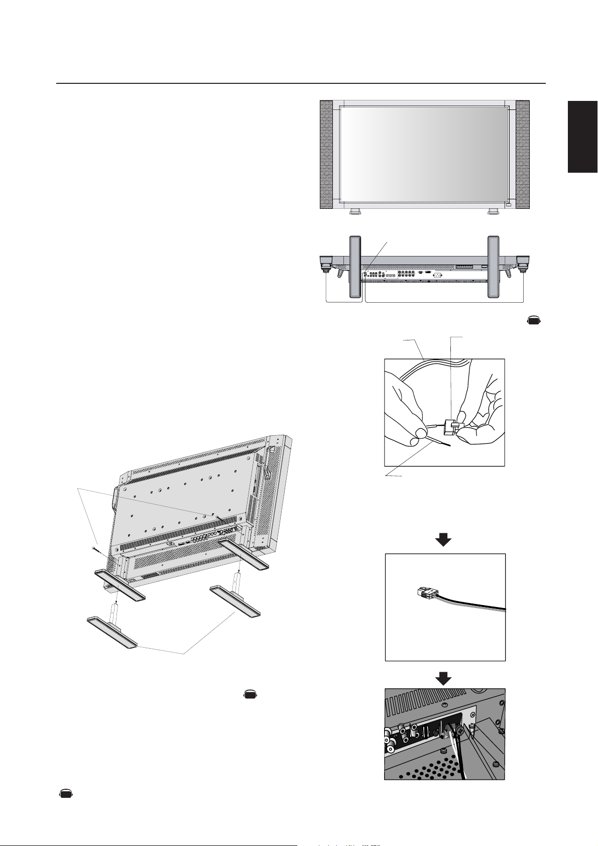
12. Installing and removing stand
How to install stand
1. Please turn monitor off.
2. Place stand onto monitor with the long ends of the feet in front
of the monitor.
3. After inserting stand in guide block, fasten thumbscrews on both
sides of the monitor.
How to remove the stand
1. Spread the protective sheet on a flat surface, such as a desk.
2. Place monitor on the protective sheet.
3. Remove thumbscrews with a screwdriver or with your fingers
and place them in a safe place for reuse.
Speaker terminal
•How to use the attached speaker plug
Standard cable
Speaker plug
English
AV
Thumbscrews
NOTE: Place stand onto monitor
so that the long end of the feet
Stand
13. When using external speakers
We recommend using the optional speakers designed for the
MultiSync LCD4010 / MultiSync LCD4610.
The external speaker terminals of the MultiSync LCD4010 / MultiSync
LCD4610 may be connected with the speaker plug of a mainframe
sound speaker. It this case, please exchange the lead connector of a
mainframe sound speaker for an attached speaker plug.
are in the front
AV
Insert the negative (-) side of a standard speaker
cable into the negative (-) side of the speaker
plug. The negative side of a standard speaker
cable has a stripe running the length of the cable.
Insert remaining wire into the positive (+) side
of the speaker plug. Hold down on the small
lever on the speaker plug to insert cable.
Fixed cable and speaker plug.
Denotes an AV unit function.
AV
All AV functions are enabled when the AV unit is installed.
Insert the fixed cable and speaker plug to the speaker terminal.
English-11
Connections
Before connecting external equipment to LCD:
* First turn off the power to all of the equipment associated with the LCD as well as that of the equipment to be connected.
* For questions regarding external equipment please refer to the user’s manual supplied with that equipment.
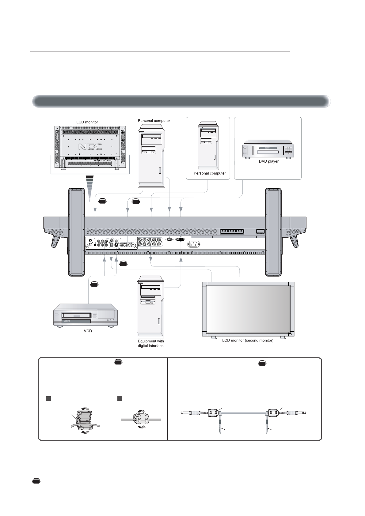
Wiring Diagram
AV
AV
Attaching the Ferrite Core Mounting Position of Ferrite Core
Attach the Ferrite Core to PC Audio Cable.
Use of the cable without mounting the ferrite core may result in the
occurrence of noise.
AV
AV
AV
• For PC Audio Cable
Open the ferrite core and clamp
1
it on the PC Audio cable.
Ferrite Core
Close the ferrite core.
2
Attach the Ferrite Core to the both ends of PC Audio Cable.
Ferrite Core
AV
Ferrite Core
Denotes an AV unit function.
AV
All AV functions are enabled when the AV unit is installed.
To AUDIO 1 of monitor
English-12
To connector of PC
Band Band
Connections –continued
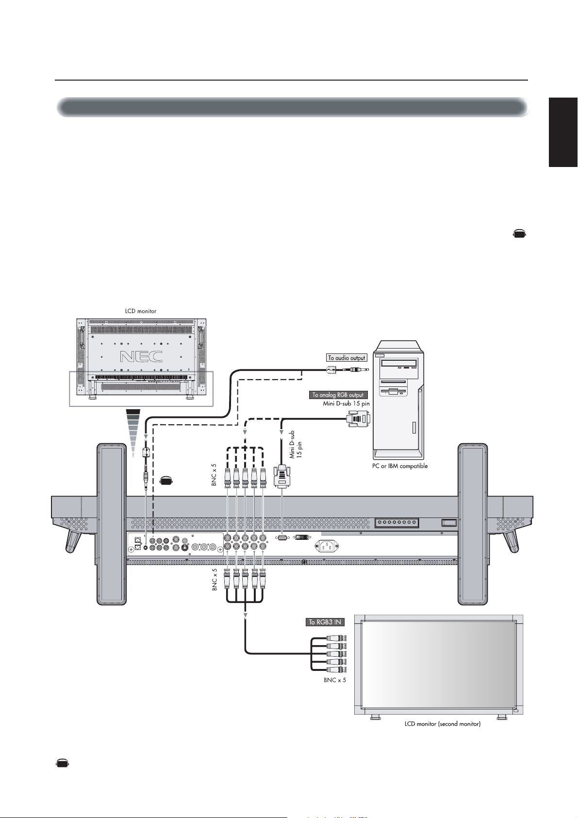
Connecting the LCD Monitor to a PC
Connecting your computer to your LCD monitor will enable you to display your computer's screen image.
Some video cards may not display an image correctly.
•To connect the RGB 2 IN connector (mini D-sub 15 pin) on the LCD monitor, use the provided RGB signal cable (mini D-sub 15 pin to
mini D-sub 15 pin).
•To connect the RGB 3 connector (BNC) on the LCD monitor, use a signal cable (mini D-sub 15 pin to BNC x 5). Select RGB 3 from the
INPUT button.
When connecting one or more LCD monitor, use the RGB OUT connector (BNC).
• The AUDIO IN 1, 2 and 3 can be used for audio input. For connection, select AUDIO 1, 2 or 3 from the AUDIO INPUT button.
AV
English
AV
Denotes an AV unit function.
AV
All AV functions are enabled when the AV unit is installed.
English-13
Connections –continued
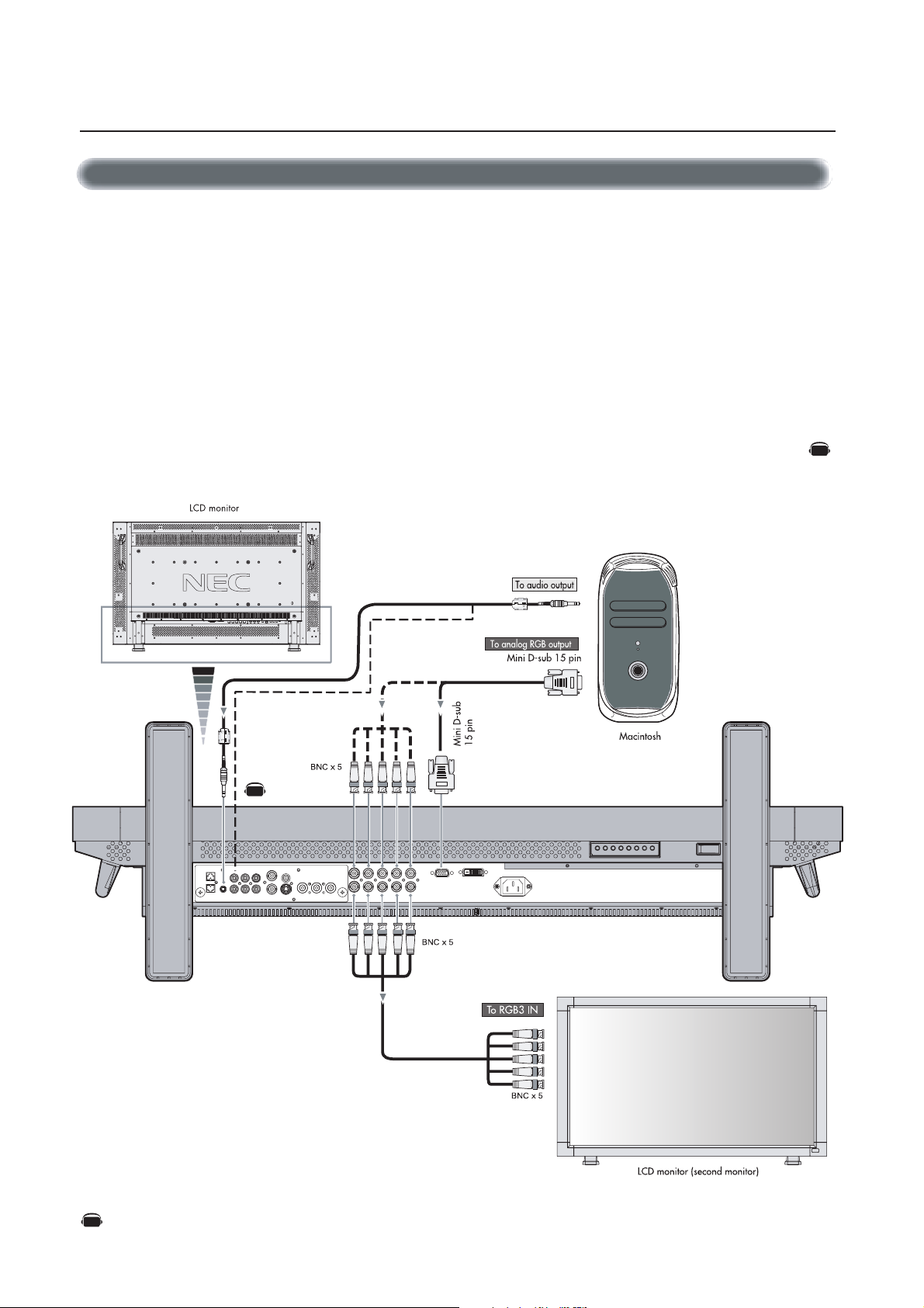
Connecting to a Macintosh® Computer
Connecting your Macintosh® computer to your LCD monitor will enable you to display your computer's screen image. Some video cards or
drivers may not display images correctly.
•To connect the RGB 2 IN connector (mini D-sub 15 pin) on the LCD monitor, use the provided RGB signal cable (mini D-sub 15 pin to
mini D-sub 15 pin).
For older Macintosh
NOTE: To obtain the Macintosh cable adapter call NEC-Mitsubishi Electronics Display of America, Inc. at (800) 632-4662
•To connect the RGB 3 IN connector (BNC) on the LCD monitor, use the signal cable available separately (mini D-sub 15 pin to
BNC x 5).
• If you will be connecting the LCD monitor to a Macintosh PowerBook, set "Mirroring" to off.
Refer to your Macintosh's owner's manual for more information about your computer's video output requirements and any special
identification or configuring that may be required.
• The AUDIO IN 1, 2 and 3 can be used for audio input. For connection, select AUDIO 1, 2 or 3 from the AUDIO INPUT button.
®
computers, use Macintosh cable adapter to connect to your Macintosh's video port.
AV
AV
Denotes an AV unit function.
AV
All AV functions are enabled when the AV unit is installed.
English-14
Connections –continued
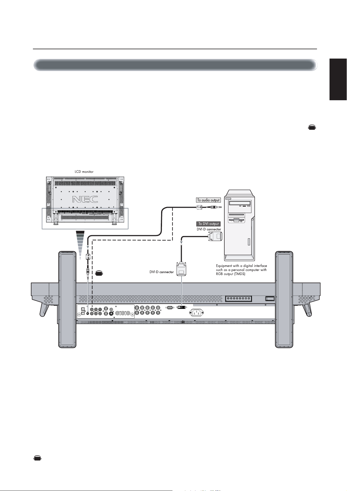
Connecting to a Computer with a Digital Output
Connections can be made with equipment that is equipped with a digital interface compliant with the DVI (Digital Visual Interface)
standard.
• The RGB 1 IN connector also accepts a DVI-D cable.
• Input TMDS signals conforming to DVI standards.
•To maintain display quality, use a cable recommended by DVI standards.
• The AUDIO IN 1, 2 and 3 can be used for audio input. For connection, select AUDIO 1, 2 or 3 from the AUDIO INPUT button.
• Mode selection see “DVI MODE” of page 25.
AV
English
AV
Denotes an AV unit function.
AV
All AV functions are enabled when the AV unit is installed.
English-15
Connections –continued
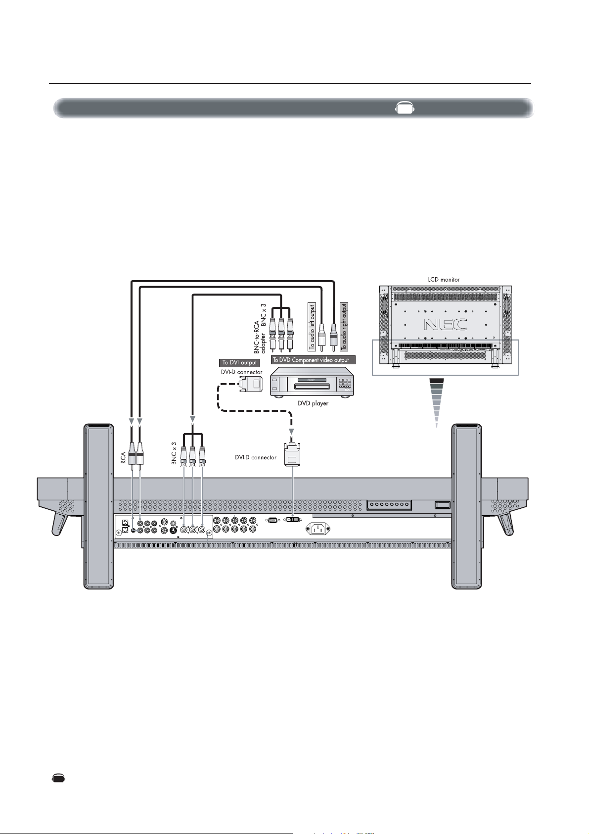
Connecting to a DVD Player
Connecting your DVD player to your LCD monitor will enable you to display your DVD video.
Refer to your DVD player’s owner’s manual for additional information.
•To connect the DVD/HD IN connector (BNC) on the LCD monitor, use a separately available BNC connector cable. You will need a
BNC-to-RCA adapter to connect a DVD player with an RCA pin jack to the BNC connector cable (not provided).
Some DVD players may have different connectors, such as DVD/HD connector (Y, Cb/Pb and Cr/Pr).
Select [DVD/HD] input mode from the INPUT button.
The AUDIO IN 2 and 3 (both RCA) can be used for audio input. For connection, select [AUDIO 2] or [AUDIO 3] from the AUDIO
INPUT button.
• Mode selection see “DVI MODE” of page 25.
AV
Denotes an AV unit function.
AV
All AV functions are enabled when the AV unit is installed.
English-16
Connections –continued
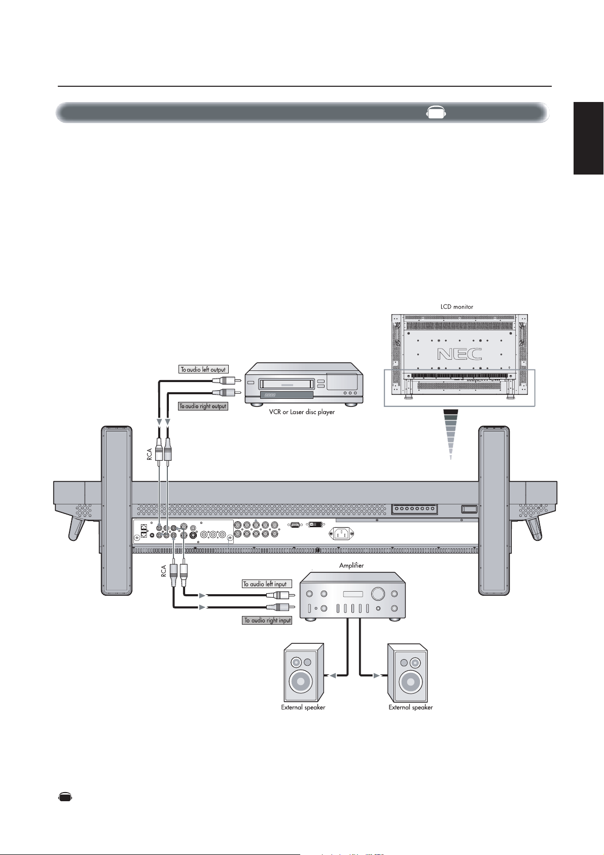
Connecting to a Stereo Amplifier
You can connect your stereo amplifier to your LCD monitor. Refer to your amplifier's owner's manual for additional information.
•Turn on the LCD monitor and the amplifier only after all connections have been made.
• Use an RCA cable to connect the AUDIO OUT connector (RCA) on the LCD monitor and the audio input on the amplifier.
• Do not reverse the audio left and right jacks.
• The AUDIO IN used for audio input.
• The AUDIO OUT jack outputs sound from the Audio input device (VCR) selected by the LCD monitor to the
external output device (stereo amplifier).
AV
English
Denotes an AV unit function.
AV
All AV functions are enabled when the AV unit is installed.
English-17
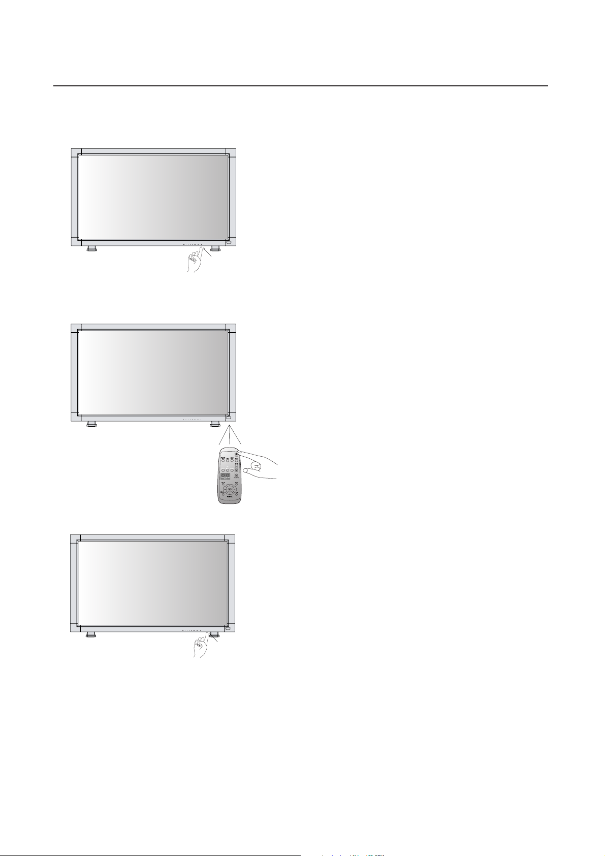
Basic Operation –Power ON and OFF Modes
The LCD monitor power indicator will turn green while powered on and will turn red while powered off. The monitor can be powered on
or off using the following three options:
1. Pressing the power button.
NOTE: Before pressing the power button, be sure to turn on
the Main Power Switch on the LCD monitor.
Power Button
2. Using the remote control
NOTE: Before operating the remote control, be sure to turn
on the Main Power Switch on the LCD monitor.
REMOTE
CONTROLLER RU-M104
Main Power Switch
3. Pressing the Main Power Switch.
NOTE: When the Main Power Switch is used to power off
the LCD, the remote control and the power button will not
activate the LCD. Be sure to turn the Main Power Switch to
“ON” before using options 1 or 2.
English-18
A
Basic Operation –continued
V
e
AV
Power Indicator
Power Indicator
Status
Power ON Green
Power OFF Red
Power Standby Red On
when “SCHEDULE” is enabled Green Blinking
Power Standby Red , Green
Diagnosis (Detecting failure) Red Blinking
*See trouble shooting of page 33
When Using Power Management Function
The LCD monitor follows the VESA approved DPM Power Management function.
The power management function is an energy saving function that
automatically reduces the power consumption of the display when
the keyboard or the mouse has not been used for a fixed period of
time.
The power management feature on your new display has been set to
the “ON” mode. This allows your display to enter a Power Saving
Mode when no signal is detected. This could potentially increase the
life and decrease the power consumption of the display.
RGB 1, 2, 3
DVD/HD, VIDEO
AV
RGB1, 2, 3
RGB2
1024 x 768
48kHz 60Hz
AUDIO : 1
SIZE : FULL
DVD/HD
DVD/HD
AUDIO : 3
SIZE : WIDE
Picture Mode
HIGHBRIGHT STANDARD sRGB
HIGHBRIGHT STANDARD CINEM
Information OSM
Video Input mode
Input signal Information
)
Audio input mode
Picture Size mode
Video Input mode
Audio input mode
Picture Size mode
English
AV
Selecting a Video Source
To view a video source:
Use the input button to set [VIDEO].
Use the COLOR SYSTEM menu to set, [AUTO], [NTSC], [PAL],
[SECAM], [PAL60], [4.43NTSC] in according to your video format.
AV
IDEO
VIDEO<S>
NTSC
AUDIO : 3
SIZE : NORMAL
AV
Video Input mode
Input Signal Color System mod
Audio input mode
Picture Size mode
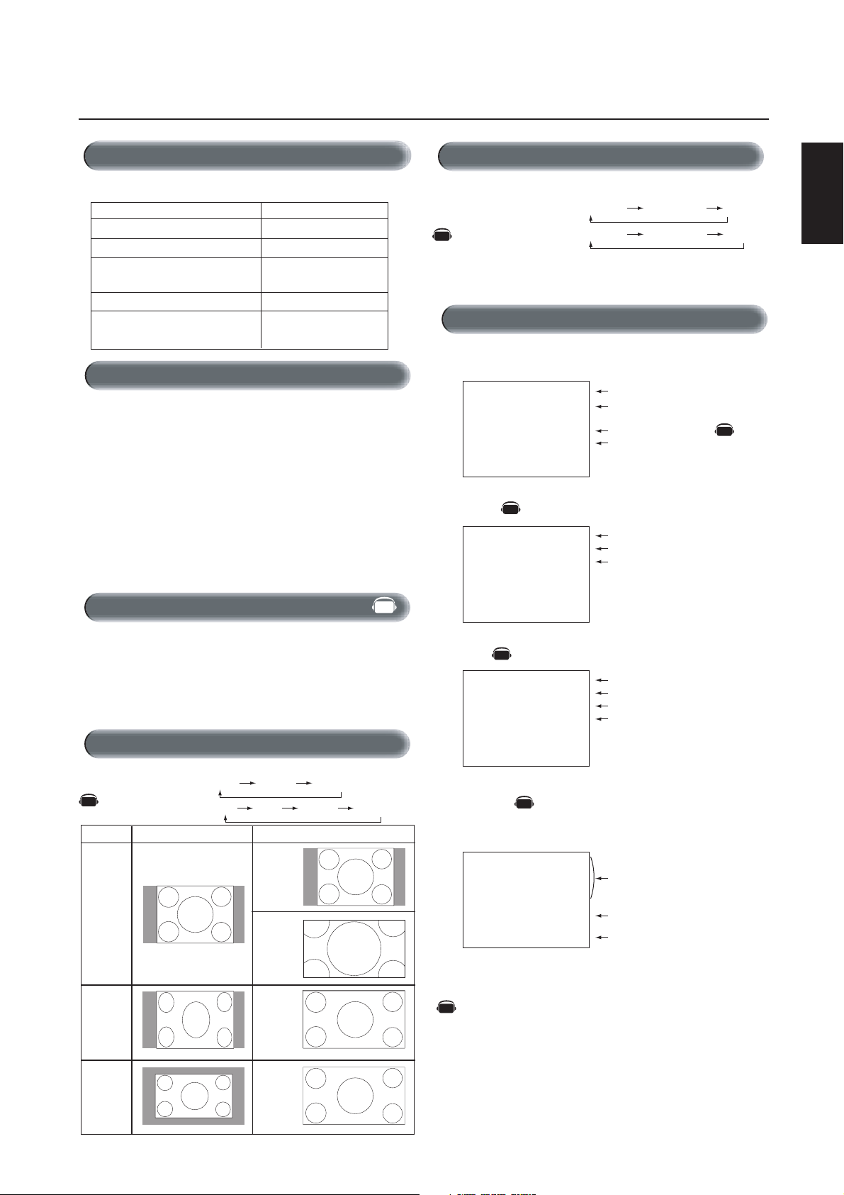
Picture Size
RGB 1, 2, 3
AV
DVD/HD, VIDEO
Signal Type
4:3
Squeeze
FULL ZOOM NORMAL
FULL WIDE ZOOM NORMAL
NORMAL SIZE RECOMMENDED SIZE
NORMAL
ZOOM
(DYNAMIC)
FULL
PIP or POP
Main:RGB2
AV
Sub:VIDEO<S>
RGB2
1024 x 768
48kHz 60Hz
AUDIO : 1
VIDEO<S>
NTSC
SIZE : FULL
Denotes an AV unit function.
AV
All AV functions are enabled when the AV unit is installed.
Main picture Information
Sub picture Information
)
Main picture Information
WIDE
Letterbox
English-19
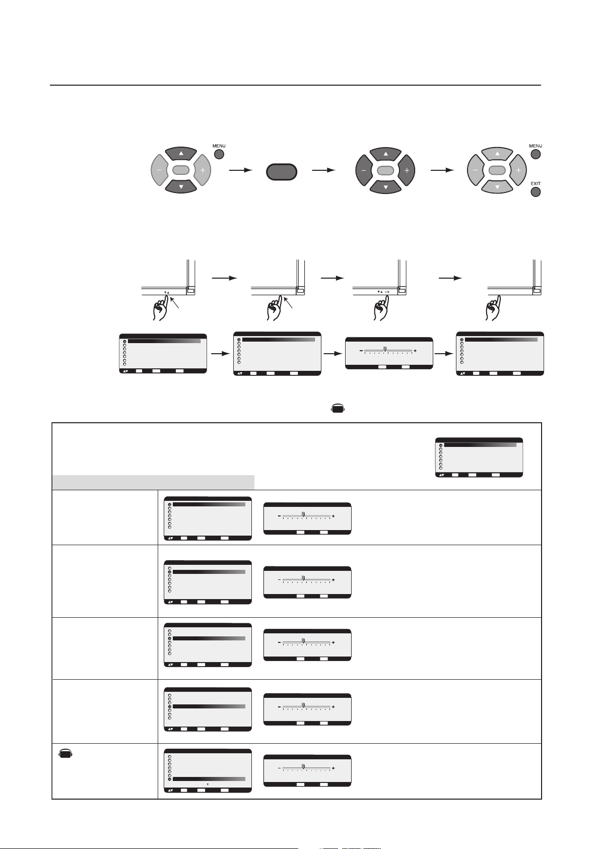
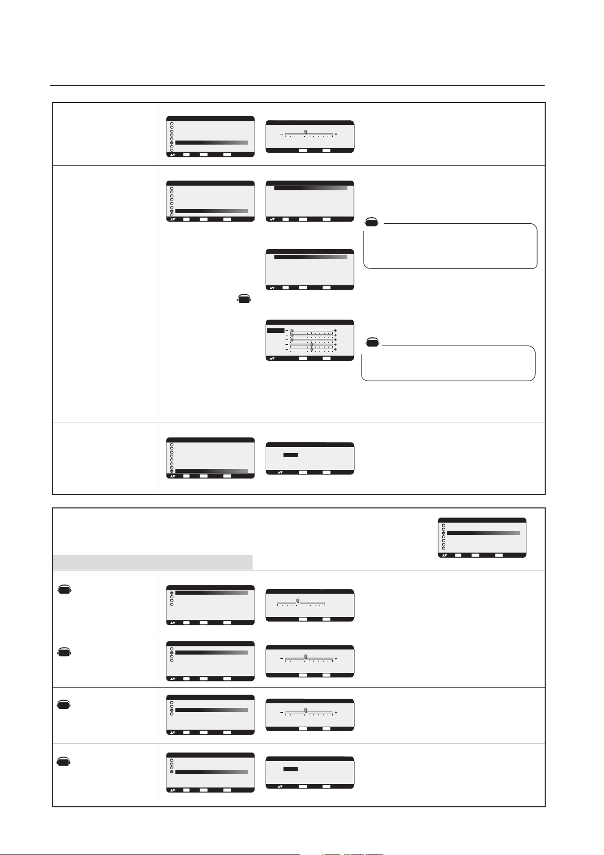
OSM (On-Screen Manager) Controls-Picture
Press MENU button to open
Main-menu
Press UP or DOWN button
to select sub-menu
Press SET button to
decide
Press the UP, DOWN, PLUS, or
MINUS buttons to select options
and to make adjustments to
settings
Press SET button to select
Remote Control
SET
Press UP or DOWN button to
select
SET
Press INPUT button to
decide
Press the UP, DOWN, PLUS, or
MINUS buttons to select options
and to make adjustments to
settings
Press INPUT button to select
SET
Control Panel
INPUT
UP or DOWN button INPUT button
PICTURE
BRIGHTNESS
CONTRAST
SHARPNESS
BLACK LEVEL
COLOR CONTROL
COLOR TEMPERATURE
PICTURE RESET
SET
:SEL
:NEXT
BRIGHTNESS
32
EXIT
:RETURN
MENU
:EXIT MENU
EXIT
MENU
:RETURN
:EXIT MENU
+ -:ADJ
OSM screen
MAIN MENU
PICTURE
SCREEN
AUDIO
PIP
CONFIGURATION 1
CONFIGURATION 2
ADVANCED OPTION
SET
:SEL
:NEXT
EXIT
MENU
:RETURN
:EXIT MENU
NOTE: Items in this OSM menu may change depending on connection type and with the AV unit installed.
Denotes an AV unit function.
AV
All AV functions are enabled when the AV unit is installed.
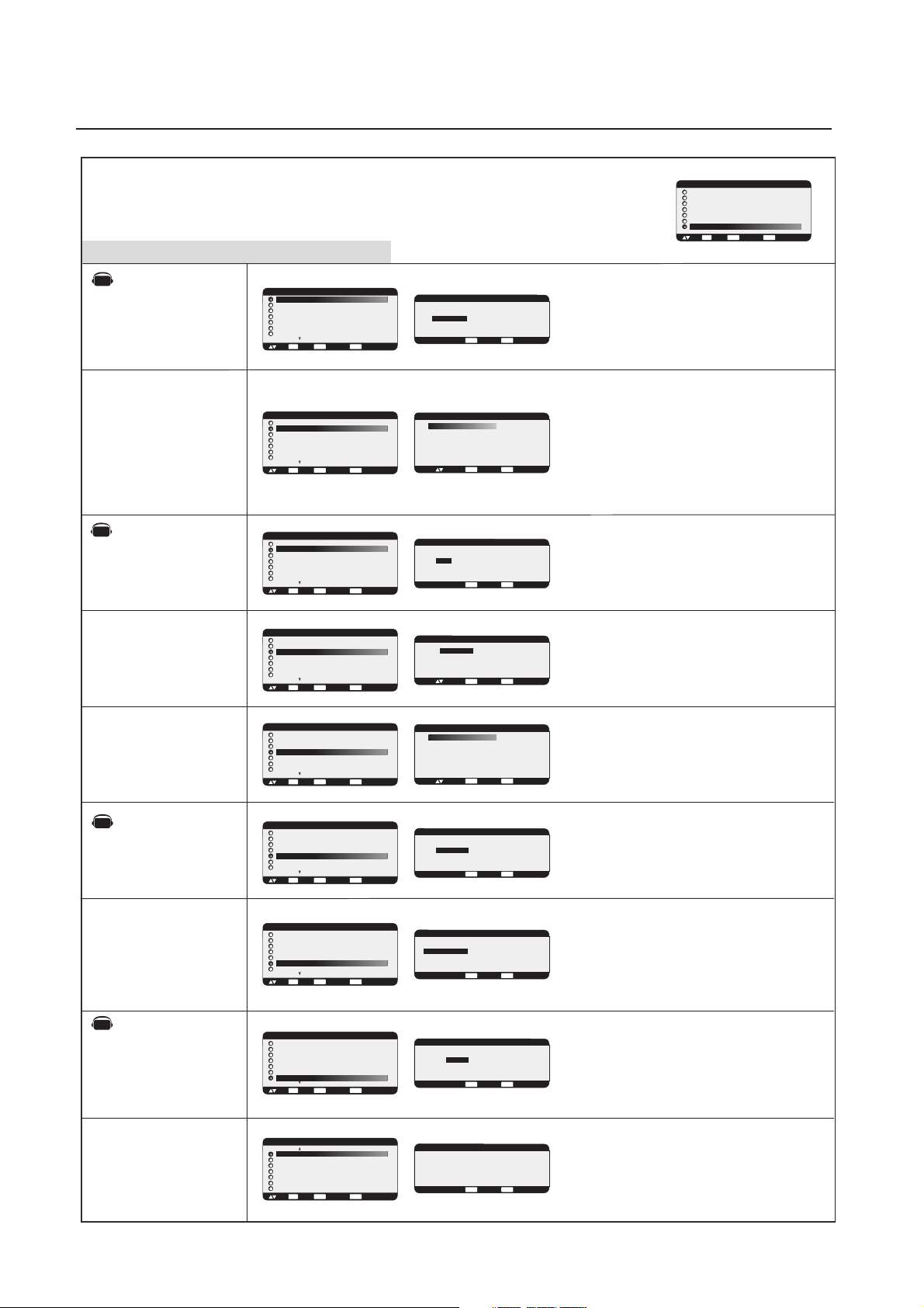
Main-Menu
PICTURE
BRIGHTNESS
Sub-Menu
PICTURE
BRIGHTNESS
CONTRAST
SHARPNESS
BLACK LEVEL
COLOR CONTROL
COLOR TEMPERATURE
PICTURE RESET
SET
:SEL
:NEXT
BRIGHTNESS
EXIT
:RETURN
MENU
:EXIT MENU
EXIT
MENU
:RETURN
:EXIT MENU
+ -:ADJ
Adjusts the overall image and background screen
brightness.
32
Press + button to increase brightness.
Press - button to decrease brightness.
MAIN MENU
PICTURE
SCREEN
AUDIO
PIP
CONFIGURATION 1
CONFIGURATION 2
ADVANCED OPTION
:SEL
Press MENU or EXIT
button to exit
Press EXIT button to
exit
PICTURE
BRIGHTNESS
CONTRAST
SHARPNESS
BLACK LEVEL
COLOR CONTROL
COLOR TEMPERATURE
PICTURE RESET
SET
EXIT
:SEL
:NEXT
SET
EXIT
:NEXT
:RETURN
SET
MENU
EXIT
:RETURN
:EXIT MENU
MENU
:EXIT MENU
CONTRAST
SHARPNESS
BLACK LEVEL
AV
NOISE REDUCTION
*:INPUT VIDEO only
PICTURE
BRIGHTNESS
CONTRAST
SHARPNESS
BLACK LEVEL
COLOR CONTROL
COLOR TEMPERATURE
PICTURE RESET
SET
:SEL
:NEXT
PICTURE
BRIGHTNESS
CONTRAST
SHARPNESS
BLACK LEVEL
COLOR CONTROL
COLOR TEMPERATURE
PICTURE RESET
SET
:SEL
:NEXT
PICTURE
BRIGHTNESS
CONTRAST
SHARPNESS
BLACK LEVEL
COLOR CONTROL
COLOR TEMPERATURE
PICTURE RESET
SET
:SEL
:NEXT
PICTURE
BRIGHTNESS
CONTRAST
SHARPNESS
TINT
COLOR
BLACK LEVEL
NOISE REDUCTION
SET
:SEL
:NEXT
Adjusts the image brightness in relation to the input
CONTRAST
EXIT
EXIT
MENU
:RETURN
:EXIT MENU
EXIT
MENU
:RETURN
:EXIT MENU
EXIT
MENU
:RETURN
:EXIT MENU
EXIT
MENU
:RETURN
:EXIT MENU
+ -:ADJ
SHARPNESS
+ -:ADJ
BLACK LEVEL
+ -:ADJ
NOISE REDUCTION
+ -:ADJ
MENU
:RETURN
:EXIT MENU
EXIT
MENU
:RETURN
:EXIT MENU
EXIT
MENU
:RETURN
:EXIT MENU
EXIT
MENU
:RETURN
:EXIT MENU
signal.
Press + button to increase contrast.
32
Press - button to decrease contrast.
NOTE: sRGB picture mode is standard and cannot be
changed.
Adjusts the crispness of what is displayed on the
screen. Can be set to get a distinct (sharp) image or a
32
soft image as is preferred. Set independently for each
Picture Mode.
Press + button to increase sharpness.
Press - button to decrease sharpness.
Adjusts the image brightness in relation to the
background.
32
Press + button to increase black level.
Press - button to decrease black level.
NOTE: sRGB picture mode is standard and cannot be
changed.
Adjusts the noise reduction level.
32
Press + button to increase reduction level.
Press - button to decrease reduction level.
English-20

OSM Controls-Screen
PICTURE
AV
TINT
*:INPUT DVD/HD,VIDEO
only
AV
COLOR
*:INPUT DVD/HD,VIDEO
only
COLOR CONTROL
*:INPUT RGB1,2,3 only
BRIGHTNESS
CONTRAST
SHARPNESS
TINT
COLOR
BLACK LEVEL
NOISE REDUCTION
SET
:SEL
:NEXT
PICTURE
BRIGHTNESS
CONTRAST
SHARPNESS
TINT
COLOR
BLACK LEVEL
NOISE REDUCTION
SET
:SEL
:NEXT
PICTURE
BRIGHTNESS
CONTRAST
SHARPNESS
BLACK LEVEL
COLOR CONTROL
COLOR TEMPERATURE
PICTURE RESET
SET
:SEL
:NEXT
EXIT
MENU
:RETURN
:EXIT MENU
EXIT
MENU
:RETURN
:EXIT MENU
EXIT
MENU
:RETURN
:EXIT MENU
TINT
+ -:ADJ
COLOR
+ -:ADJ
COLOR CONTROL
R
Y
G
C
B
M
S
+ -:ADJ
:SEL
Adjusts the tint of the screen.
32
Press + button the flesh tone color becomes greenish.
EXIT
MENU
:RETURN
:EXIT MENU
Press - button
the flesh tone
color becomes purplish.
English
Adjusts the color depth of the screen.
32
Press + button to increase color depth.
EXIT
MENU
:RETURN
:EXIT MENU
EXIT
MENU
:RETURN
:EXIT MENU
Press - button to decrease color depth.
R, Y, G, C, B, M, S: Increases or decreases Red, Yellow,
Green, Cyan, Blue, Magenta and Saturation depending upon
0
which is selected. The change in color will appear on screen
0
0
and the direction (increase or decrease) will be shown by the
0
0
color bars.
0
NOTE: sRGB picture mode is standard and cannot be
0
changed.
COLOR
TEMPERATURE
PICTURE RESET
Main-Menu
SCREEN
Sub-Menu
H POSITION
V POSITION
PICTURE
BRIGHTNESS
CONTRAST
SHARPNESS
BLACK LEVEL
COLOR CONTROL
COLOR TEMPERATURE
PICTURE RESET
SET
:SEL
:NEXT
PICTURE
BRIGHTNESS
CONTRAST
SHARPNESS
BLACK LEVEL
COLOR CONTROL
COLOR TEMPERATURE
PICTURE RESET
SET
:SEL
:NEXT
SCREEN
H POSITION
V POSITION
CLOCK
CLOCK PHASE
H RESOLUTION
V RESOLUTION
ZOOM MODE
SCREEN RESET
SET
:SEL
:NEXT
SCREEN
H POSITION
V POSITION
CLOCK
CLOCK PHASE
H RESOLUTION
V RESOLUTION
ZOOM MODE
SCREEN RESET
SET
:SEL
:NEXT
COLOR TEMPERATURE
EXIT
:RETURN
MENU
:EXIT MENU
EXIT
MENU
:RETURN
:EXIT MENU
+ -:ADJ
Adjusts the color temperature of entire screen.
Choosing a lower color temperature will make the
9600K
screen reddish and a higher color temperature make
the screen bluish.
NOTE: sRGB picture mode is standard and cannot be
changed.
PICTURE RESET
NO
YES
EXIT
EXIT
MENU
:RETURN
:EXIT MENU
EXIT
MENU
:RETURN
:EXIT MENU
EXIT
MENU
:RETURN
:EXIT MENU
:SEL
H POSITION
+ -:ADJ
V POSITION
+ -:ADJ
MENU
:RETURN
:EXIT MENU
EXIT
MENU
:RETURN
:EXIT MENU
EXIT
MENU
:RETURN
:EXIT MENU
Selecting Picture Reset allows you to reset all OSM
settings within the PICTURE menu.
Select "YES" and press "SET" button to restore the
factory settings.
Press "EXIT" button to cancel and Press "EXIT" again to
return the previous menu.
MAIN MENU
PICTURE
SCREEN
AUDIO
PIP
CONFIGURATION 1
CONFIGURATION 2
ADVANCED OPTION
SET
EXIT
:SEL
:NEXT
:RETURN
Controls Horizontal Image position within the display
area of the LCD.
0
Press + button to move screen to right.
Press - button to move screen to left.
Controls Vertical Image position within the display
area of the LCD.
0
Press + button to move screen to UP.
Press - button to move screen to DOWN.
MENU
:EXIT MENU
CLOCK
*:INPUT RGB2/3 only
CLOCK PHASE
*:INPUT RGB2/3 only
H RESOLUTION
*:INPUT RGB1/2/3 only
SCREEN
H POSITION
V POSITION
CLOCK
CLOCK PHASE
H RESOLUTION
V RESOLUTION
ZOOM MODE
SCREEN RESET
SET
:SEL
SCREEN
H POSITION
V POSITION
CLOCK
CLOCK PHASE
H RESOLUTION
V RESOLUTION
ZOOM MODE
SCREEN RESET
SET
:SEL
SCREEN
H POSITION
V POSITION
CLOCK
CLOCK PHASE
H RESOLUTION
V RESOLUTION
ZOOM MODE
SCREEN RESET
SET
:SEL
:NEXT
:NEXT
:NEXT
CLOCK
EXIT
EXIT
MENU
:RETURN
:EXIT MENU
EXIT
MENU
:RETURN
:EXIT MENU
EXIT
MENU
:RETURN
:EXIT MENU
+ -:ADJ
CLOCK PHASE
+ -:ADJ
H RESOLUTION
+ -:ADJ
MENU
:RETURN
:EXIT MENU
EXIT
MENU
:RETURN
:EXIT MENU
EXIT
MENU
:RETURN
:EXIT MENU
Press + button to expand the width of the image on the
screen to the right.
1782
Press - button to narrow the width of the image on the
screen to the left.
Adjusts the visual snow noise on the image.
18
Adjusts the horizontal size by increasing or decreasing
the setting.
Press + button to expand the width of the image on the
1360
screen.
Press - button to narrow the width of the image on the
screen.
English-21
OSM Controls-Audio
V RESOLUTION
*:INPUT RGB1/2/3 only
ZOOM MODE
SCREEN RESET
SCREEN
H POSITION
V POSITION
CLOCK
CLOCK PHASE
H RESOLUTION
V RESOLUTION
ZOOM MODE
SCREEN RESET
SET
:SEL
SCREEN
H POSITION
V POSITION
CLOCK
CLOCK PHASE
H RESOLUTION
V RESOLUTION
ZOOM MODE
SCREEN RESET
SET
:SEL
SCREEN
H POSITION
V POSITION
CLOCK
CLOCK PHASE
H RESOLUTION
V RESOLUTION
ZOOM MODE
SCREEN RESET
SET
:SEL
:NEXT
:NEXT
:NEXT
V RESOLUTION
EXIT
:RETURN
MENU
:EXIT MENU
EXIT
MENU
:RETURN
:EXIT MENU
+ -:ADJ
ZOOM MODE
CUSTOM
OFF
Adjusts the vertical size by increasing or decreasing
the setting.
Press + button to expand the height of the image on
768
the screen.
Press - button to narrow the height of the image on the
screen.
Selects the screen zoom mode. "ZOOM" mode can
be selected pressing the "SIZE" button on the remote
control.
When you select the "CUSTOM" setting, you will be
EXIT
MENU
:RETURN
:EXIT MENU
SET
EXIT
:SEL
:NEXT
:RETURN
MENU
:EXIT MENU
*:INPUT RGB1/2/3 only
able to set custom horizontal and vertical size.
AV
When you select the "16:9" setting, the screen will
stretch 4:3 to 16:9 and then you will be able to
ZOOM MODE
CUSTOM
16:9
14:9
DYNAMIC
OFF
SET
EXIT
:SEL
:NEXT
:RETURN
AV
*:INPUT DVD/HD, VIDEO only
CUSTOM
ZOOM
H ZOOM
V ZOOM
H POS
V POS
:SEL + - :ADJ
EXIT
:RETURN
MENU
MENU
:EXIT MENU
:EXIT MENU
adjust optional horizontal and vertical size.
(INPUT DVD/HD, VIDEO only)
Press "SET" button to show the control menu as
follows,
Increase or decrease "ZOOM" slider to adjust the
whole size. Adjust horizontal size with H ZOOM and
vertical size with V ZOOM. Increase or decrease "H
POS" and "V POS" to adjust the picture position.
X 1.00
X 1.00
X 1.00
AV
0%
0%
Selecting "DYNAMIC" will expand 4:3 picture to fill the
screen with non-linearity. (Some of the image is lost due
to expansion.) Dynamic image is the same as FULL size
image when HDTV 1080i or 720p signal is input
Selecting "OFF" will display the image in a 1 by
1pixel format. (If the input resolution is higher than a
1366 x 768 resolution, the image will be scaled
down to fit the screen.)
Selecting Screen reset allows you to reset all OSM
SCREEN RESET
NO
YES
EXIT
:RETURN
MENU
:EXIT MENU
EXIT
MENU
:RETURN
:EXIT MENU
:SEL
settings within SCREEN menu.
Select "YES" and press "SET" button to restore the
factory preset data.
Press "EXIT" button to cancel. Press "EXIT" again to
return the previous menu.
Main-Menu
AUDIO
AV
BALANCE
AV
TREBLE
AV
BASS
AV
AUDIO RESET
Sub-Menu
AUDIO
BALANCE
TREBLE
BASS
AUDIO RESET
:SEL
AUDIO
BALANCE
TREBLE
BASS
AUDIO RESET
:SEL
AUDIO
BALANCE
TREBLE
BASS
AUDIO RESET
:SEL
AUDIO
BALANCE
TREBLE
BASS
AUDIO RESET
:SEL
MAIN MENU
PICTURE
SCREEN
AUDIO
PIP
CONFIGURATION 1
CONFIGURATION 2
ADVANCED OPTION
SET
EXIT
:SEL
:NEXT
BALANCE
L
SET
EXIT
:NEXT
SET
:NEXT
SET
:NEXT
SET
:NEXT
MENU
:RETURN
:EXIT MENU
EXIT
MENU
:RETURN
:EXIT MENU
EXIT
MENU
:RETURN
:EXIT MENU
EXIT
MENU
:RETURN
:EXIT MENU
+ -:ADJ
TREBLE
+ -:ADJ
BASS
+ -:ADJ
AUDIO RESET
NO
YES
:SEL
R CENTER
EXIT
MENU
:RETURN
:EXIT MENU
EXIT
MENU
:RETURN
:EXIT MENU
EXIT
MENU
:RETURN
:EXIT MENU
EXIT
MENU
:RETURN
:EXIT MENU
Adjusts the balance of stereo sound.
Press + button to move the stereo sound image to right.
Sound of the left side will be quieter.
Press - button to move the stereo sound image to left.
Sound of the right side will be quieter.
Adjusts the high frequency sound.
0
Press + button to increase TREBLE sound.
Press - button to decrease TREBLE sound.
Asjusts the low frequency sound.
0
Press + button to increase BASS sound.
Press - button to decrease BASS sound.
Selecting Audio reset allows you to reset all OSM
settings fwithin Audio menu.
Select "YES" and press "SET" button to restore the
factory preset.
Press "EXIT" button to cancel. Press "EXIT" again to
:RETURN
MENU
:EXIT MENU
return the previous menu.
English-22

OSM Controls-Configuration1
Main-Menu
PICTURE IN PICTURE
Sub-Menu
AV
PIP SIZE
AV
PIP AUDIO
AV
PIP RESET
AV
PIP
:SEL
PIP
:SEL
PIP
:SEL
PIP SIZE
PIP AUDIO
PIP RESET
SET
PIP SIZE
PIP AUDIO
PIP RESET
SET
PIP SIZE
PIP AUDIO
PIP RESET
SET
:NEXT
:NEXT
:NEXT
MAIN MENU
PICTURE
SCREEN
AUDIO
PIP
CONFIGURATION 1
CONFIGURATION 2
ADVANCED OPTION
SET
EXIT
:SEL
:NEXT
PIP SIZE
LARGE
MIDDLE
SMALL
EXIT
:RETURN
MENU
:EXIT MENU
EXIT
MENU
:RETURN
:EXIT MENU
:SEL
Selects the size of picture inserted in the 'Picture-inPicture' (PIP) mode.
'Large', 'Middle' and 'Small' are available.
:RETURN
MENU
:EXIT MENU
English
Selects the sound source for the PIP mode.
PIP AUDIO
MAIN AUDIO / PIP AUDIO
EXIT
:RETURN
MENU
:EXIT MENU
EXIT
MENU
:RETURN
:EXIT MENU
+ -:SEL
When selecting 'MAIN AUDIO', you will get the sound
from the main picture and when selecting 'PIP AUDIO',
you will get the sound for the picture-in-picture instead.
When side-by-side modes, MAIN AUDIO is the sound
source of the left side screen and PIP AUDIO is the
right side.
PIP RESET
NO
YES
EXIT
:RETURN
MENU
:EXIT MENU
EXIT
MENU
:RETURN
:EXIT MENU
:SEL
Selecting PIP Reset allows you to reset all OSM settings
within the PIP menu.
Select "YES" and press "SET" button to restore the
factory preset data.
Press "EXIT" button to cancel. Press "EXIT" again to
return the previous menu.
Main-Menu
CONFIGURATION 1
Sub-Menu
AUTO SETUP
*:INPUT RGB2/3 only
AUTO ADJUST
*:INPUT RGB2/3 only
AUTO BRIGHTNESS
*:INPUT RGB1/2/3 only
POWER SAVE
CONFIGURATION 1
AUTO SETUP
AUTO ADJUST
AUTO BRIGHTNESS
POWER SAVE
LANGUAGE
SCREEN SAVER
SIDE BORDER COLOR
SET
:SEL
:NEXT
CONFIGURATION 1
AUTO SETUP
AUTO ADJUST
AUTO BRIGHTNESS
POWER SAVE
LANGUAGE
SCREEN SAVER
SIDE BORDER COLOR
SET
:SEL
:NEXT
CONFIGURATION 1
AUTO SETUP
AUTO ADJUST
AUTO BRIGHTNESS
POWER SAVE
LANGUAGE
SCREEN SAVER
SIDE BORDER COLOR
SET
:SEL
:NEXT
CONFIGURATION 1
AUTO SETUP
AUTO ADJUST
AUTO BRIGHTNESS
POWER SAVE
LANGUAGE
SCREEN SAVER
SIDE BORDER COLOR
SET
:SEL
:NEXT
MAIN MENU
PICTURE
SCREEN
AUDIO
PIP
CONFIGURATION 1
CONFIGURATION 2
ADVANCED OPTION
SET
EXIT
:SEL
:NEXT
AUTO SETUP
SET
PRESS
TO AUTO SETUP
SET
EXIT
MENU
:CANCEL
:RETURN
:RETURN
MENU
MENU
:EXIT MENU
:EXIT MENU
:EXIT MENU
EXIT
MENU
:RETURN
:EXIT MENU
EXIT
MENU
:RETURN
:EXIT MENU
EXIT
MENU
:RETURN
:EXIT MENU
:SETUP
AUTO ADJUST
ON / OFF
+ -:SEL
AUTO BRIGHTNESS
ON / OFF
+ -:SEL
EXIT
EXIT
Press "SET" button to automatically adjust screen size,
horizontal position, vertical position, clock, clock
phase and black level.
Press "EXIT" button to cancel AUTO SETUP. Press
"EXIT" again to return to the previous menu.
Selects the auto adjust ON/OFF.
When ON is selected the horizontal position, vertical
position, and clock-phase will adjust automatically.
Turns the Auto Brightness ON/OFF.
When "ON" is selected, the Brightness will adjust
automatically.
:RETURN
MENU
:EXIT MENU
Selects RGB "ON", the monitor will go to power
POWER SAVE
RGB ON / OFF
VIDEO ON / OFF
EXIT
:RETURN
MENU
:EXIT MENU
+ -:ADJ
EXIT
MENU
:RETURN
:EXIT MENU
:SEL
management mode when RGB1,2,3 sync signal is lost.
AV
Select VIDEO "ON", the monitor will go to power
management mode after about 10 minutes delay from
when DVD/HD and VIDEO input signal is lost.
LANGUAGE
CONFIGURATION 1
AUTO SETUP
AUTO ADJUST
AUTO BRIGHTNESS
POWER SAVE
LANGUAGE
SCREEN SAVER
SIDE BORDER COLOR
SET
:SEL
:NEXT
LANGUAGE
ENGLISH
DEUTSCH
FRANCAIS
ESPAÑOL
ITALIANO
SVENSKA
EXIT
:RETURN
MENU
:EXIT MENU
EXIT
:SEL
:RETURN
MENU
:EXIT MENU
OSM control menus are available in seven languages.
English-23

OSM Controls-Configuration2
SCREEN SAVER
GAMMA
COOLING FAN
BRIGHTNESS
MOTION
EXIT
+ -:ADJ
:SEL
COLOR SYSTEM
AUTODEUTSCH
NTSC
PAL
SECAM
4.43 NTSC
PAL-60
EXIT
:SEL
SIDE BORDER COLOR
EXIT
+ -:ADJ
CONFIGURATION RESET
NO
YES
EXIT
:SEL
FACTORY RESET
NO
YES
EXIT
:SEL
ON / OFF
ON / AUTO
ON / OFF
1 SEC.
:RETURN
:RETURN
:RETURN
:RETURN
:RETURN
MENU
MENU
MENU
MENU
MENU
SCREEN SAVER
AV
COLOR SYSTEM
*:INPUT VIDEO only
SIDE BORDER
COLOR
CONFIGURATION
RESET
FACTORY RESET
CONFIGURATION 1
AUTO SETUP
AUTO ADJUST
AUTO BRIGHTNESS
POWER SAVE
LANGUAGE
SCREEN SAVER
SIDE BORDER COLOR
SET
EXIT
:SEL
:NEXT
CONFIGURATION 1
POWER SAVE
LANGUAGE
SCREEN SAVER
COLOR SYSTEM
SIDE BORDER COLOR
CONFIGURATION RESET
FACTORY RESET
SET
EXIT
:SEL
:NEXT
CONFIGURATION 1
AUTO BRIGHTNESS
POWER SAVE
LANGUAGE
SCREEN SAVER
COLOR SYSTEM
SIDE BORDER COLOR
CONFIGURATION RESET
FACTORY RESET
SET
EXIT
:SEL
:NEXT
CONFIGURATION 1
POWER SAVE
LANGUAGE
SCREEN SAVER
COLOR SYSTEM
SIDE BORDER COLOR
CONFIGURATION RESET
FACTORY RESET
SET
EXIT
:SEL
:NEXT
CONFIGURATION 1
POWER SAVE
LANGUAGE
SCREEN SAVER
COLOR SYSTEM
SIDE BORDER COLOR
CONFIGURATION RESET
FACTORY RESET
SET
EXIT
:SEL
:NEXT
:RETURN
:RETURN
:RETURN
:RETURN
:RETURN
MENU
MENU
MENU
MENU
MENU
:EXIT MENU
:EXIT MENU
:EXIT MENU
:EXIT MENU
:EXIT MENU
:EXIT MENU
:EXIT MENU
:EXIT MENU
:EXIT MENU
:EXIT MENU
Select "SCREEN SAVER" settings to reduce the risk of
"Image Persistence".
GAMMA: The display gamma is changed and fixed
when "ON" is selected.
COOLING FAN: The built in cooling fan is always on
when set to "ON".
BRIGHTNESS: The brightness is decreased when "ON"
is selected.
MOTION: Image is slightly expanded and moved 4
directions (UP, DOWN, RIGHT, LEFT) periodically (time
setting is adjustable).
Movement area is approximately +/- 10mm from
original position, please locate the important information
such as text within 90% area of screen image.
See note(1) for these functions.
PIP, POP, Side by Side and STILL will be disabled when
"MOTION" is active
Selecting the color System depends on your input video
format.
AUTO: NTSC, PAL, SECAM, PAL60 or 4.43NTSC
is automatically selected.
NTSC: Specific selection of NTSC.
PAL: Specific selection of PAL.
SECAM: Specific selection of SECAM.
PAL-60: Specific selection of PAL60.
4.43 NTSC: Specific selection of 4.43 NTSC.
Adjusts the side black bar color between black and
white when 4:3 image displayed.
50
Press + button, the bar will become whiter.
Press - button, the bar will become darker.
Selecting CONFIGURATION reset allows you to reset all
CONFIGURATION settings.
Select "YES" and press "SET" button to restore the
factory preset data.
Press "EXIT" button to cancel and then return the previous
menu.
Selecting "YES" allows you to reset PICTURE, SCREEN,
AUDIO, CONFIGURATION1,2 and ADVANCE OPTION
back to factory settings (except LANGUAGE,
DATE & TIME and SCHEDULE).
Select "YES" and press "SET" button to restore the factory
preset data.
Press "EXIT" button to cancel and return to the previous
menu.
Main-Menu
CONFIGURATION 2
Sub-Menu
LONG CABLE
ON/OFF
*:INPUT RGB2/3 only
LONG CABLE
MANUAL
*:INPUT RGB2/3 only
CONFIGURATION 2
LONG CABLE ON/OFF
LONG CABLE MANUAL
OSM TURN OFF
INFORMATION OSM
OFF TIMER
OSM POSITION
INPUT DETECT
MONITOR INFORMATION
SET
EXIT
:SEL
:NEXT
CONFIGURATION 2
LONG CABLE ON/OFF
LONG CABLE MANUAL
OSM TURN OFF
INFORMATION OSM
OFF TIMER
OSM POSITION
INPUT DETECT
MONITOR INFORMATION
SET
EXIT
:SEL
:NEXT
:RETURN
:RETURN
MENU
MENU
:EXIT MENU
:EXIT MENU
LONG CABLE ON/OFF
ON / OFF
EXIT
+ -:SEL
LONG CABLE MANUAL
RED DELAY
GREEN DELAY
BLUE DELAY
RED SHARPNESS
GREEN SHARPNESS
BLUE SHARPNESS
SOG PEAK
VIDEO EQ.
SYNC TERMINATE
NEXT
:SEL
+ -:ADJ
:RETURN
:RETURN
MENU
MENU
:EXIT MENU
0
2
0
0
0
0
0
0
HI / LO
:EXIT MENU
MAIN MENU
PICTURE
SCREEN
AUDIO
PIP
CONFIGURATION 1
CONFIGURATION 2
ADVANCED OPTION
SET
EXIT
:SEL
:NEXT
:RETURN
MENU
:EXIT MENU
Automaticallly adjusts the display to compensate for
image degradation caused by using a long cable.
Please refer to the CD-ROM included for alteration.
To compensate for image degradation, which is caused
by using a long cable.
RED/GREEN/BLUE DELAY
To adjust the phase of the RED, GREEN and BLUE
signals.
LEVEL: 0 - 6
RED/GREEN/BLUE SHARPNESS
Adjusts the performance degradation of the RED,
GREEN and BLUE signals.
LEVEL: 0 - 45
SOG PEAK
Adjusts the shape of Sync on Green signal.
Level: 0 - 1
VIDEO EQ (Input RGB 3 only)
Optimize the shape (Tailing) of RED, GREEN and BLUE
signal.
Level: 0 - 7
SYNC TERMINATE (Input RGB 3 only)
Selects the terminate resistance for matching the cable
impedance.
HI: 2.2K ohm / LO:75 ohm
English-24

OSM Controls-Configuration2
OSM TURN OFF
INFORMATION
OSM
OFF TIMER
DVI MODE
*:INPUT RGB1 only
OSM POSITION
CONFIGURATION 2
LONG CABLE ON/OFF
LONG CABLE MANUAL
OSM TURN OFF
INFORMATION OSM
OFF TIMER
OSM POSITION
INPUT DETECT
MONITOR INFORMATION
SET
EXIT
:SEL
:NEXT
CONFIGURATION 2
LONG CABLE ON/OFF
LONG CABLE MANUAL
OSM TURN OFF
INFORMATION OSM
OFF TIMER
OSM POSITION
INPUT DETECT
MONITOR INFORMATION
SET
EXIT
:SEL
:NEXT
CONFIGURATION 2
LONG CABLE ON/OFF
LONG CABLE MANUAL
OSM TURN OFF
INFORMATION OSM
OFF TIMER
OSM POSITION
INPUT DETECT
MONITOR INFORMATION
SET
EXIT
:SEL
:NEXT
CONFIGURATION 2
OSM TURN OFF
INFORMATION OSM
OFF TIMER
DVI MODE
OSM POSITION
INPUT DETECT
MONITOR INFORMATION
SET
EXIT
:SEL
:NEXT
CONFIGURATION 2
LONG CABLE ON/OFF
LONG CABLE MANUAL
OSM TURN OFF
INFORMATION OSM
OFF TIMER
OSM POSITION
INPUT DETECT
MONITOR INFORMATION
SET
EXIT
:SEL
:NEXT
:RETURN
:RETURN
:RETURN
:RETURN
:RETURN
MENU
MENU
MENU
MENU
MENU
:EXIT MENU
:EXIT MENU
:EXIT MENU
:EXIT MENU
:EXIT MENU
OSM TURN OFF
10 SEC.
EXIT
+ -:ADJ
INFORMATION OSM
ON 10 SEC.
OFF
EXIT
+ -:ADJ
:SEL
OFF TIMER
ON 1 HOUR
OFF
EXIT
+ -:ADJ
:SEL
DVI MODE
DVI-PC / DVI-HD
EXIT
+ -:SEL
OSM POSITION
+ - :ADJ
EXIT
UP
DOWN
:RETURN
:RETURN
:RETURN
:RETURN
:RETURN
MENU
MENU
MENU
MENU
RIGHTLEFT
MENU
:EXIT MENU
:EXIT MENU
:EXIT MENU
:EXIT MENU
:EXIT MENU
The OSM control menu will stay on as long as it is in
use. In the OSM Turn Off submenu, you can select how
long the monitor waits after the last touch of a button to
shut off the OSM control menu. The preset choices are
10 -240 seconds.
English
Selects whether the information OSM is displayed or
not. The information OSM will be displayed when the
input signal or source changes. the information OSM
will also give a warning when there is no-signal or
the signal is out-of range.
A time between 3 to 10 seconds is available.
To select OFF TIMER mode ON/OFF.
In the OFF TIMER menu, you can preset the
monitor to automatically power down.
A time between 1 to 24 hours is available.
When the OFF TIMER is set, the SCHEDULE
(see page 27) settings will be disabled. OFF TIMER is
not reset when monitor is shut off.
Selects the kind of DVI-D equipment which is connected
to RGB1.
Select "DVI-PC" when PC or other computer equipment is
connected.
Select "DVI-HD" when DVD player which has DVI-D
output is connected.
Adjusts the position of the OSM menu.
Press + button to move right side of the screen.
Press - button to move left side of the screen.
Press button to move top side of the screen.
Press button to move down side of the screen.
INPUT DETECT
MONITOR
INFORMATION
CONFIGURATION 2
LONG CABLE ON/OFF
LONG CABLE MANUAL
OSM TURN OFF
INFORMATION OSM
OFF TIMER
OSM POSITION
INPUT DETECT
MONITOR INFORMATION
SET
EXIT
:SEL
:NEXT
CONFIGURATION 2
LONG CABLE ON/OFF
LONG CABLE MANUAL
OSM TURN OFF
INFORMATION OSM
OFF TIMER
OSM POSITION
INPUT DETECT
MONITOR INFORMATION
SET
EXIT
:SEL
:NEXT
:RETURN
:RETURN
MENU
MENU
:EXIT MENU
:EXIT MENU
INPUT DETECT
FIRST
DETECT
LAST
DETECT
VIDEO
DETECT
NONE
EXIT
:SEL
MONITOR INFORMATION
MODEL NAME:
LCD4010
SERIAL:
12315XXX
EXIT
:RETURN
:RETURN
MENU
MENU
:EXIT MENU
:EXIT MENU
Selects the method of input detection when more than
two input devices are connected.
FIRST DETECT: When the current video input signal is
not present, then the monitor searches for a video signal
from the other video input port. If the video signal is
present in the other port, then the monitor switches the
video source input port to the new found video source
automatically. The monitor will not look for other video
signals while the current video source is present.
This function is available at input RGB 1/2/3.
LAST DETECT: When the monitor is displaying a signal
from the current source and a new secondary source is
supplied to the monitor, the monitor will automatically
switch to the new video source. When current video
input signal is not present, the monitor searches for a
video signal from the other video input port. If the video
signal is present in the other port, then the monitor
switches the video source input port to the new found
video source automatically.
This function is available at input RGB 1/2/3.
AV
VIDEO DETECT: DVD/HD or VIDEO inputs will have
priority over RGB1/2/3. When DVD/HD or VIDEO
input signal is present the monitor will change and keep
to the DVD/DH or VIDEO input.
NONE: The Monitor will not search the other video
input port.
Indicates the model and serial number of your
monitor.
English-25
OSM Controls-Advanced option
Main-Menu
ADVANCED OPTION
Sub-Menu
AV
S-VIDEO MODE
INPUT RESOLUTION
*:INPUT RGB2/3 only
AV
BLACK LEVEL
EXPANSION
*:INPUT VIDEO only
GAMMA SELECTION
ADVANCED OPTION
S-VIDEO MODE
BLACK LEVEL EXPANSION
GAMMA SELECTION
IMAGE FLIP
SCAN MODE
SCAN CONVERSION
FILM MODE
SET
EXIT
:SEL
:NEXT
ADVANCED OPTION
S-VIDEO MODE
INPUT RESOLUTION
GAMMA SELECTION
IMAGE FLIP
MONITOR ID
TILE MATRIX
HEAT PROTECT
SET
EXIT
:SEL
:NEXT
ADVANCED OPTION
S-VIDEO MODE
BLACK LEVEL EXPANSION
GAMMA SELECTION
IMAGE FLIP
SCAN MODE
SCAN CONVERSION
FILM MODE
SET
EXIT
:SEL
:NEXT
ADVANCED OPTION
S-VIDEO MODE
BLACK LEVEL EXPANSION
GAMMA SELECTION
IMAGE FLIP
SCAN MODE
SCAN CONVERSION
FILM MODE
SET
EXIT
:SEL
:NEXT
:RETURN
:RETURN
:RETURN
:RETURN
MENU
MENU
MENU
MENU
:EXIT MENU
:EXIT MENU
:EXIT MENU
:EXIT MENU
S-VIDEO MODE
PRIORITY / SEPARATE
EXIT
:RETURN
+ -:SEL
INPUT RESOLUTION
AUTO
1024 X 768
1280 X 768
1360 X 768
EXIT
:RETURN
:SEL
BLACK LEVEL EXPANSION
HIGH / MIDDLE / OFF
EXIT
+ -:SEL
:RETURN
GAMMA SELECTION
2. 2
2. 4
S GAMMA
NATIVE
EXIT
:SEL
:RETURN
MENU
MENU
MENU
MENU
:EXIT MENU
:EXIT MENU
:EXIT MENU
:EXIT MENU
MAIN MENU
PICTURE
SCREEN
AUDIO
PIP
CONFIGURATION 1
CONFIGURATION 2
ADVANCED OPTION
SET
EXIT
:SEL
:NEXT
:RETURN
MENU
:EXIT MENU
Selects the S-Video input port function.
PRIORITY:
If cable is connected to the S-Video input, it will have
priority over the composite input port.
SEPARATE:
S-Video port and Composite port can be selected as
independent input ports.
Sets of the resolution of input signal to one of the
following: 1024x768, 1280x768 and 1360x768.
AUTO: Determines the resolution automatically.
1024x768 : Sets the resolution to 1024x768
1280x768 : Determines the resolution to 1280x768
1360x768 : Determines the resolution to 1360x768
Selects a level of black expansion.
To prevent going under the black cut-off level, please
adjust the "Black Level" in moderation on the OSM
menu.
Selects a display gamma.
1: 2.2
2: 2.4
3: S gamma
4: Native
NOTE: sRGB picture mode is standard
and cannot be changed.
IMAGE FLIP
AV
SCAN MODE
*:INPUT DVD/HD,
VIDEO only
SCAN
CONVERSION
AV
FILM MODE
*:INPUT DVD/HD,
VIDEO only
MONITOR ID
ADVANCED OPTION
S-VIDEO MODE
BLACK LEVEL EXPANSION
GAMMA SELECTION
IMAGE FLIP
SCAN MODE
SCAN CONVERSION
FILM MODE
SET
EXIT
:SEL
:NEXT
:RETURN
ADVANCED OPTION
S-VIDEO MODE
BLACK LEVEL EXPANSION
GAMMA SELECTION
IMAGE FLIP
SCAN MODE
SCAN CONVERSION
FILM MODE
SET
EXIT
:SEL
:NEXT
:RETURN
ADVANCED OPTION
S-VIDEO MODE
BLACK LEVEL EXPANSION
GAMMA SELECTION
IMAGE FLIP
SCAN MODE
SCAN CONVERSION
FILM MODE
SET
EXIT
:SEL
:NEXT
:RETURN
ADVANCED OPTION
S-VIDEO MODE
BLACK LEVEL EXPANSION
GAMMA SELECTION
IMAGE FLIP
SCAN MODE
SCAN CONVERSION
FILM MODE
SET
EXIT
:SEL
:NEXT
:RETURN
ADVANCED OPTION
MONITOR ID
IR CONTROL
TILE MATRIX
HEAT STATUS
POWER ON DELAY
DATE & TIME
SCHEDULE
ADVANCED OPTION RESET
SET
EXIT
:SEL
:NEXT
:RETURN
MENU
MENU
MENU
MENU
MENU
:EXIT MENU
:EXIT MENU
:EXIT MENU
:EXIT MENU
:EXIT MENU
IMAGE FLIP
NORMAL
H MIRROR
V MIRROR
ROTATE
EXIT
:RETURN
:SEL
SCAN MODE
OVERSCAN / UNDERSCAN
EXIT
+ -: SEL
:RETURN
SCAN CONVERSION
PROGRESSIVE / INTERLACE
EXIT
+ -: SEL
:RETURN
FILM MODE
AUTO / OFF
EXIT
+ -: SEL
:RETURN
MONITOR ID
ID No. 1
EXIT
+ -: SEL
:RETURN
MENU
MENU
MENU
MENU
MENU
:EXIT MENU
:EXIT MENU
:EXIT MENU
:EXIT MENU
:EXIT MENU
Selects how the image is flipped or rotated.
NORMAL: normal display.
H MIRROR: Mirror image for horizontal direction.
V MIRROR: Mirror image for vertical direction.
ROTATE: Rotate the image 180 degrees.
Changes the display area of the image.
OVER SCAN: Set to display area about 95%
UNDER SCAN: Set to display area about 100%
Selects IP (Interlace to Progressive) converter function.
PROGRESSIVE: Enable the IP function, to convert
interlace signal to progressive.
[NOTE] This mode is the normal setting.
INTERLACE: Disable the IP function.
[NOTE] This mode is better suited for motion
pictures, but increases the risk of image retention.
Selects Film mode function.
AUTO: Enables the Film mode function. This mode is
better suited for movies which are converted to 24
Frames/sec source to DVD Video. We recommend
selecting "PROGRESSIVE" in the "SCAN
CONVERSION" setting.
OFF: Disable the Film mode function. This mode is better
suited for Broadcasting or VCR source.
Sets the monitor ID number used to control the daisy
chained multiple MultiSync LCD4010s / MultiSync
LCD4610s with RS-232C.
The Monitor ID number can be between 1 and 26.
English-26
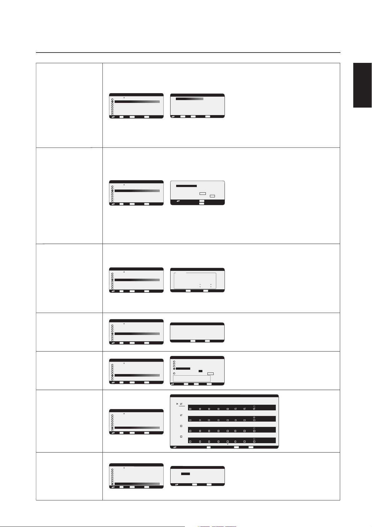
OSM Controls-Advanced option
IR CONTROL
TILE MATRIX
ADVANCED OPTION
MONITOR ID
IR CONTROL
TILE MATRIX
HEAT STATUS
POWER ON DELAY
DATE & TIME
SCHEDULE
ADVANCED OPTION RESET
SET
EXIT
:SEL
:NEXT
ADVANCED OPTION
MONITOR ID
IR CONTROL
TILE MATRIX
HEAT STATUS
POWER ON DELAY
DATE & TIME
SCHEDULE
ADVANCED OPTION RESET
SET
EXIT
:SEL
:NEXT
:RETURN
:RETURN
MENU
MENU
:EXIT MENU
:EXIT MENU
IR CONTROL
NORMAL
PRIMARY
SECONDARY
LOCK
:SEL
TILE MATRIX
H MONITORS
V MONITORS
POSITION
TILE COMP
ENABLE
:SEL
+ -: ADJ
EXITSET
:RETURN:SET
MENU
MENU
1
1
1
YES / NO
YES / NO
EXIT
:RETURN
:EXIT MENU
:EXIT MENU
Selects the infra-red wireless remote controllers mode with
using the RS-232C daisy chain.
The item in this menu will become effective by pressing
"SET" button on the selected item.
NORMAL: The monitor will be controlled normally by
wireless remote controller.
PRIMARY: Set "PRIMARY" at the head of the daisy
chained monitors by RS-232C.
SECONDARY: Set "SECONDARY" after 2nd daisy
chained monitor.
LOCK: Disable the monitor control by infra-red wireless
remote controller.
Keep pressing "DISPLAY" button for 5 or more seconds,
this setting will return to "NORMAL".
See "NOTE 2" on page 28
The "TILE MATRIX" feature allows one image to be
displayed on multiple screens. This feature can be used
with up to 25 monitors. (5 horizontal x 5 vertical)
Using the Tile Matrix function requires the PC output signal
to be sent through a distribution amplifier to each
individual monitor.
H MONITORS: Selects the number of horizontal displays.
V MONITORS: Selects the number of vertical displays.
POSITION: Selects a position to expand the screen.
TILE COMP: Works in tandem with "TILE MATRIX" to
compensate for the width of the tiled bezels in order to
accurately display the image.
ENABLE: Select "YES", to expand the signal to the
selected settings.
PIP, POP, SIDE by SIDE, STILL and DYNAMIC zoom mode
will be disabled when the "TILE MATRIX" is activated.
Note: LCD4010 and LCD4610 Displays can NOT be
used together with the Tile Matrix function.
English
HEAT STATUS
POWER ON DELAY
DATE & TIME
SCHEDULE
ADVANCED OPTION
MONITOR ID
IR CONTROL
TILE MATRIX
HEAT STATUS
POWER ON DELAY
DATE & TIME
SCHEDULE
ADVANCED OPTION RESET
SET
EXIT
:SEL
:NEXT
ADVANCED OPTION
MONITOR ID
IR CONTROL
TILE MATRIX
HEAT STATUS
POWER ON DELAY
DATE & TIME
SCHEDULE
ADVANCED OPTION RESET
SET
EXIT
:SEL
:NEXT
ADVANCED OPTION
MONITOR ID
IR CONTROL
TILE MATRIX
HEAT STATUS
POWER ON DELAY
DATE & TIME
SCHEDULE
ADVANCED OPTION RESET
SET
EXIT
:SEL
:NEXT
ADVANCED OPTION
MONITOR ID
IR CONTROL
TILE MATRIX
HEAT STATUS
POWER ON DELAY
DATE & TIME
SCHEDULE
ADVANCED OPTION RESET
SET
EXIT
:SEL
:NEXT
:RETURN
:RETURN
:RETURN
:RETURN
MENU
MENU
MENU
MENU
:EXIT MENU
:EXIT MENU
:EXIT MENU
:EXIT MENU
Displays status of COOLING FAN, BRIGHTNESS and
TEMPERATURE.
HEAT STATUS
STATUS
COOLING FAN1 ON
COOLING FAN2 ON
BRIGHTNESS NORMAL
TEMPERATURE
SENSOR 1 0.0 C / 32.0 F
SENSOR 2 0.0 C / 32.0 F
EXIT
:RETURN
MENU
:EXIT MENU
COOLING FAN activates when the inside temperature
exceeds highest recommended operating temperature
BRIGHTNESS decreases when inside temperature
exceeds highest recommended operating temperature
with cooling fan running. In this case a warning is
displayed on the screen.
POWER ON DELAY
3 SEC.
EXIT
+ -:ADJ
DATE & TIME
YEAR
MONTH
DAY
TIME
DAYLIGHT SAVING YES / NO
CURRENT DATE TIME
JAN. 01. 2004 00 : 00 : 00
SET
+ -:ADJ
:SEL
SCHEDULE
1
2
3
4
+ - :SEL
MENU
:RETURN
:EXIT MENU
2004
JANUARY
01
00 : 00
:SET
EXIT
MENU
:EXIT MENU
:RETURN
TODAY THURSDAY, JAN. 01. 2004 10:00
ON
OFF
1 0 : 0 0
1 7 : 0 0 EVERY DAY
MON TUE WED THU FRI SAT SUN EVERY WEEK
ON
OFF
1 1 : 0 0
1 8 : 0 0 EVERY DAY
MON TUE WED THU FRI SAT SUN EVERY WEEK
ON
OFF
0 0 : 0 0
1 0 : 0 0 EVERY DAY
MON TUE WED THU FRI SAT SUN EVERY WEEK
ON
OFF
0 0 : 0 0
1 0 : 0 0 EVERY DAY
MON TUE WED THU FRI SAT SUN EVERY WEEK
SET
: SET
Adjusts the delay time from "standby" to "power on"
mode.
"POWER ON DELAY" can be set between
0 and 50 sec.
Sets the current date and time for internal clock.
Date and time has to be set in order for the
"SCHEDULE" function to work properly.
INPUT
RGB 1
INPUT
RGB 1
INPUT
RGB 1
INPUT
RGB 1
EXIT
:RETURN
MENU
:EXIT MENU
Programs the monitor's
working schedule.
Sets the hour and day of the
week when the monitor
powers on or off. Also sets
the input port.
Select "EXIT" to set schedule.
(see "NOTE 3" on page 28
for further information)
ADVANCED
OPTION RESET
ADVANCED OPTION
MONITOR ID
IR CONTROL
TILE MATRIX
HEAT STATUS
POWER ON DELAY
DATE & TIME
SCHEDULE
ADVANCED OPTION RESET
SET
EXIT
:SEL
:NEXT
:RETURN
MENU
:EXIT MENU
ADVANCED OPTION RESET
NO
YES
EXIT
:SEL
:RETURN
English-27
MENU
:EXIT MENU
Selecting ADVANCED OPTION RESET allows you to
reset all OSM settings from the ADVANCED OPTION
settings, except for DATE & TIME, and SCHEDULE.
Select "YES" and press "SET" button to restore the
factory preset data.
Press "EXIT" button to cancel and then return the
previous menu.

OSM Controls-NOTE
NOTE 1: IMAGE PERSISTENCE
Please be aware that LCD Technology may experience a phenomenon known as Image Persistence. Image Persistence occurs when a
residual or “ghost” image of a previous image remains visible on the screen. Unlike CRT monitors, LCD monitors’ image persistence
is not usually permanent, but constant images being displayed for a long period of time should be avoided since there may be a
“semi-permanent” effect.
To alleviate image persistence, turn off the monitor for as long as the previous image was displayed. For example, if an image was on
the monitor for one hour and a residual image remains, the monitor should be turned off for one hour to erase the image.
As with all personal display devices, NEC-Mitsubishi Electronics Display recommends displaying moving images and using a moving
screen saver at regular intervals whenever the screen is idle or turning off the monitor when not in use.
Please set “SCREEN SAVER”, “DATE & TIME” and “SCHEDULE” functions to further reduce the risk of Image persistence.
NOTE 2: MONITOR ID and IR CONTROL
Using the one PC or one infra-red wireless controller, you can control up to 26 MultiSync LCD4010 / LCD4610 monitors that are connected
in a daisy chain by an RS-232C.
1. Connect a PC and MultiSync LCD4010 / LCD4610.
Connect a PC's RS-232C control output to the MultiSync LCD4010's / LCD4610’s RS-232C input.
You can connect the MultiSync LCD4010's / LCD4610’s RS-232C output to another MultiSync LCD4010's / LCD4610’s RS-232C input.
(refer to page 29)
2. Set Monitor ID.
Set "MONITOR ID" in the "ADVANCED OPTION" menu.
"MONITOR ID" should be set to a unique number, from 1 to 26, on all daisy chained MultiSync LCD4010’s / LCD4610’s.
We recommend numbering each monitor within a daisy chain sequentially from 1.
Set "PRIMARY" to "IR CONTROL" in the "ADVANCED OPTION" menu on the first monitor in the daisy chain.
Set "SECONDARY" to "IR CONTROL" on other monitors.
3. Press the "DISPLAY" button on the remote control while aiming at the
“PRIMARY” monitor. The ID select OSM will be shown at
top left side of the screen.
ID: (Displays the ID number of the current monitor within the daisy chain)
ID No. (Displays the ID number of the monitor that can be controlled via
daisy chain by the current monitor)
Press "+" or "-" buttons to change the "ID No." of the monitor to be controlled. To control all of the daisy chained monitors simultaneously, select “ALL” as the “ID No.”
4. Use the wireless remote controller to control the “SECONDARY” monitor while aiming at the "PRIMARY" monitor.
The "MENU OSM" of the “SECONDARY” monitor will appear on the selected “PRIMARY” monitor and you will be able to control the
“SECONDARY” MONITOR by via the remote controller, without interfering with the function of the “PRIMARY” monitor.
[NOTE] If the "ID No." mode select OSM is showing, press the "DISPLAY" button on the remote control while pointing at the “PRIMARY”
monitor to clear this OSM.
[HINT] If you lost control due to the wrong setting of "IR CONTROL", pressing the "DISPLAY" button on the remote control for 5 or more
seconds will reset the "IR CONTROL" menu to "NORMAL" function.
ID: 1
ID No: 2
Monitor ID
Monitor ID (ID of the monitor to be controlled)
NOTE 3: HOW TO SETUP SCHEDULE
Using the “SCHEDULE” function allows you to set up to seven different scheduled time intervals when the LCD Monitor will be activated. You
can select the time the monitor turns on and turns off, the day of week the monitor is activated, and which input source the monitor will use
for each scheduled activation period. A check mark in the box next to the number of the schedule indicates that the selected schedule is in
effect.
To select which schedule to set, use the up/down arrows to move the red bar vertically under the number (1 to 7) of the schedule. Use the
(+) and (-) buttons to move the red bar horizontally within the particular schedule. The “SET” button is used to make a selection.
If you create a schedule but do not want to use a power on time, select “--” in the “ON” time slot.
If you do not want to use a power off time select “--” in the OFF time slot.
If there is no input selected (“--” showing in the input spot) the input from the previous schedule will be used.
The selection of EVERY DAY within a schedule takes priority over other schedules that are set up to operate weekly.
When schedules are overlapping, scheduled Power ON time has priority over scheduled Power OFF time.
If there are two schedules programmed for the same time, then the highest numbered schedule has priority.
When the “OFF TIMER” (see page 25) is set, the “SCHEDULE” function is disabled.
English-28

Using the LCD with a Personal Computer (PC)
This LCD monitor can be controlled by connecting to a personal computer with an RS-232C terminal.
Functions that can be controlled by a personal computer are:
• Powering ON or OFF
• Switching between input signals
Connection
LCD Monitor + PC
OUT
IN
English
PC
RS-232C Cable
Note: If your PC (IBM or IBM compatible) is equipped only with a 25-pin serial port connector, a 25-pin serial port adapter
is required. Contact your dealer for details.
* RS-232C OUT terminal can connect to MultiSync LCD4010 / LCD4610 only. Do not connect to other equipment.
The following control sequence is used for a single MultiSync LCD4010 / MultiSync LCD4610. To control multiple LCD4010 / MultiSync LCD4610
monitors that are daisy-chained together please use the extended control command. Instructions for the extended control command can be found
on the CD included with the display. The file is called "External_control_LCD4x10.pdf". When using the following control commands, all of the
daisy-chained monitors can be controlled at the same time from one monitor. Reply and status commands, however, will only pertain to the primary
monitor, not seconday monitors.
1) Interface
PROTOCOL
BAUD RATE
DATA LENGTH
PARITY BIT
STOP BIT
FLOW CONTROL
This LCD monitor uses RXD, TXD and GND lines for RS-232C control.
For RS-232C cable, the reverse type cable should be used.
RS-232C
9600 [bps]
8 [bits]
NONE
1 [bits]
NONE
to RS-232C
"IN" terminal
from RS-232C
"OUT" terminal
RS-232C Cable
to RS-232C
"IN" terminal
from RS-232C
"OUT" terminal
Next MultiSync LCD4010/
MultiSync LCD4610
RS-232C "IN" terminal
2) Control command diagram
The command is structured by the address code, function code, data code and end code. The length of the
command is different for each function.
HEX
ASCII
Address code
30h 30h
'0' '0'
[Address code]
[Function code]
[Data code]
[End code]
Function code
Function
Function
30h 30h (In ASCII code, '0' '0') fixed.
A code of each fixed control move.
A code of each fixed control data (number) and not always indicated.
0Dh (In ASCII code, ' ' ) fixed.
Data code
Data
Data
End code
0Dh
English-29

Using the LCD with a Personal Computer –continued
3) Control sequence
(1) The command from a personal computer to the LCD monitor will take 400ms.
(2) The LCD monitor will send a return command 400ms* after it has received an encode. If the command isn't
received correctly, the LCD monitor will not send the return command.
(3) The personal computer checks the command and confirms if the command which has been sent has been
executed or not.
(4) This LCD monitor sends various codes other than the return code. When sending a control sequence via
RS-232C, other codes from personal computers will be ignored.
*: The sending time of the return command may be delayed depending on the monitor's current activity
(changing of the input signal, etc.).
[Example] Turn the power ON ( ' ' is for ASCII code)
Sending commands
from the PC etc.
30 30 21 0D
'0' '0' '!' ' '
Status code from LCD
monitor
30 30 21 0D
'0' '0' '!' ' '
Meaning
Command for POWER ON
Command received
(Command echo back)
4) Operation commands
The operation commands execute the basic operation setting of this LCD monitor.
It may not operate when changing the signal:
Operation
POWER ON
POWER OFF
INPUT RGB 1
INPUT RGB 2
INPUT RGB 3
INPUT VIDEO
INPUT DVD/HD
• POWER OFF command should not be used less than 1 minute after the power is turned on.
• POWER ON command should not be used less than 1 minute after the power is turned off.
NOTE: mark is an AV-unit function.
All AV functions are enabled when the AV-unit is installed.
5) Read command
AV
Host computer sends the command without Data-code to monitor.
After receiving this command, the monitor returns the command with Data-code of current
status to host computer.
<ex> When Host computer checks the Power status of monitor, the status of monitor is powered-on.
ASCII
!
"
_r1
_r2
_r3
AV
_v1
AV
_v2
HEX
21h
22h
5Fh 72h 31h
5Fh 72h 32h
5Fh 72h 33h
5Fh 76h 31h
5Fh 76h 32h
Command from computer
30 30 76 50 0D
'0''0''v''P'[enter]
Command from Monitor
30 30 76 50 31 0D
'0''0''v''1'[enter]
English-30
Detail of command
Ask about the power
status of monitor.
Monitor is powered-on.

Using the LCD with a Personal Computer –continued
Structure of the Read-command
HEX
Data (Receive)
31
30
72 31
72 32
72 33
76 31
76 32
70 31
70 32
2B 20 32 35
2E 30
2B 20 32 35
2B 20 33 30 2E 35
2B 20 33 31
POWER
Input
Picture mode
Temperature
of Internal
monitor
ON
OFF(stand by)
RGB-1(DVI-D)
RGB-2(D-sub)
RGB-3(BNC)
Video
DVD/HD
Hi Bright
Standard
Around
Power
PCB
Around
Power
PCB
resolution
0.5 C
resolution
1 C
resolution
0.5 C
resolution
1 C
AV
AV
Function
vP
vP
vI
vI
vI
vI
vI
vM
vM
tcx1
tc1
tcx2
tc2
ASCII
Data (Receive)
1
0
r1
r2
r3
v1
v2
p1
p2
(ex.) +25.0
(ex.)+25
(ex.)+30.5
(ex.)+31
Function
76 50
76 50
76 49
76 49
76 49
76 49
76 49
76 4D
76 4D
74 63 78 31
74 63 31
74 63 78 31
74 63 32
English
NOTE: For complete information please see file "External_Control_LCD4x10.pdf" on the CD-ROM.
AV
Mark is an AV-unit function.
All AV functions are enabled when the AV-unit is installed.
English-31

Features
40” or 46” diagonal screen size adds a new dimension to information display technology.
1366 x 768 resolution allows for crisp text and precise images.
XtraView
®
technology allows for wide-angle viewing.
DDC/CI capabilities allow control commands to be sent directly to the monitor through a standard PC or over an existing
network by a system administrator.
CableComp™ automatic long cable compensation prevents image quality degradation caused by long cable lengths.
User-friendly, efficient design features the currently proposed VESA-standard mounting and an overall lightweight
construction for easy transport and installation.
Optional detachable speakers deliver an enhanced multimedia experience with amazing sound quality.
Low power consumption and reduced heat emission lead to a lower total cost of ownership.
®
On Screen Manager (OSM
) puts you in complete control of display setting adjustments.
NEC’s quality and reliability provide peace of mind with a 1-year warranty (including backlight) and 24/7 customer
service and technical support.
Reduced Footprint: Provides the ideal solution for environments requiring superior image quality but with size and weight
reductions. The monitor’s small footprint and low weight allow it to be moved or transported easily from one location to
another.
®
AccuColor
Control System with sRGB allows you to change between the color settings on your display to match your
personal preference.
OmniColor™ Control System with sRGB color-matching uses 6-axis color data to ensure true-to-life color reproduction for
still images and real-time videos.
®
Plug and Play: The Microsoft
setup and installation by allowing
solution with the Windows®95/98/ME/2000/XP operating system facilitates
the monitor to send its capabilities (such as screen size and resolutions supported)
directly
to your computer, automatically optimizing display performance.
Intelligent Power Manager (IPM
®
) System provides innovative power-saving methods, saving two-thirds of your monitor
energy costs.
Multiple Frequency Technology automatically adjusts monitor to the display card’s scanning frequency, thus displaying
the resolution required.
FullScan® Capability allows you to use the entire screen area in most resolutions, significantly expanding image size.
VESA® Standard Mounting Interface allows users to connect their LCD monitor to any VESA standard third party mount-
ing arm or bracket. Allows for the monitor to be mounted on a wall or an arm using any third party compliant device.
NEC recommends using mounting interface that comply with UL1678 standard in North America.
DVI-D: The digital-only subset of DVI created by the Digital Display Working Group (DDWG) for digital connections
between computers and displays. As a digital-only connector, analog support is not provided off a DVI-D connector. As
a DVI-based digital only connection, only a simple adapter is necessary for compatibility between DVI-D and other DVIbased digital connectors such as DFP and P&D.
TILE MATRIX, TILE COMP: Allows multiple screens to display one image, tiled over several stacked monitors that are and
compensates within the image for the bezel width.
ZOOM: Expands the image individually for horizontal and vertical direction.
RS-232C daisy chain: you can control the multiple monitors by controller or wireless remote controller.
Self-diagnosis: If an internal error should occur, a failure state will be indicated.
English-32

Troubleshooting
No picture
• The signal cable should be properly connected to the display card/computer.
• The display card should be properly seated in its slot.
• Front Power Switch and computer power switch should be in the ON position.
• Check to make sure that a supported mode has been selected on the display card or system being used. (Please consult display card
or system manual to change graphics mode.)
• Check the monitor and your display card with respect to compatibility and recommended settings.
• Check the signal cable connector for bent or pushed-in pins.
Power Button does not respond
• Unplug the power cord of the monitor from the AC outlet to turn off and reset the monitor.
Image persistence
• Please be aware that LCD Technology may experience a phenomena known as Image Persistence. Image Persistence occurs when a
residual or “ghost” image of a previous image remains visible on the screen. Unlike CRT monitors, LCD monitors’ image persistence is not
permanent, but constant images being displayed for a long period of time should be avoided. To alleviate image persistence, turn off the
monitor for as long as the previous image was displayed. For example, if an image was on the monitor for one hour and a residual image
remains, the monitor should be turned off for one hour to erase the image.
NOTE: As with all personal display devices, NEC-Mitsubishi Electronics Display recommends using a moving screen saver at regular
intervals whenever the screen is idle or turning off the monitor when not in use.
Image is unstable, unfocused or swimming is apparent
• Signal cable should be properly attached to the LCD monitor, computer, or other input device.
• Use the OSM screen controls to focus and adjust display by increasing or decreasing the clock phase total. When the display mode
is changed, the OSM Image Adjust settings may need to be readjusted.
• Check the monitor and your display card with respect to compatibility and recommended signal timings.
• If your text is garbled, change the video mode to non-interlace and use 60Hz refresh rate.
Image of component signal is greenish
• Check to see if the DVD/HD input connector is selected.
LED on monitor is not lit (no green or red color can be seen)
• Main Power Switch should be in the ON position and power cord should be connected.
• Make certain the computer is not in a power-saving mode (touch the keyboard or mouse).
Red LED on monitor is blinking
•A certain failure might have occurred, please contact your nearest authorized NEC-Mitsubishi Electronics Display service facility.
Display image is not sized properly
• Use the OSM screen controls to increase or decrease the clock total.
• Check to make sure that a supported mode has been selected on the display card or system being used. (Please consult display card
or system manual to change graphics mode.)
Selected resolution is not displayed properly
• Use OSM information to enter Information menu and confirm that the appropriate resolution has been selected. If not, select
appropriate resolution.
No Sound
• Check to see if speaker cable is properly connected.
• Check to see if mute is activated.
• Check to see if volume is set at minimum.
Remote Control is not available
•Test the Remote Control’s batteries for strength/life.
• Check if the batteries are inserted correctly.
• Check if the Remote Control is pointed at the monitor’s remote sensor.
“SCHEDULE” / ”OFF TIMER” functions not working properly
• The “SCHEDULE” function will be disabled when the “OFF TIMER” is set.
• If the “OFF TIMER” function is enabled and the power to the LCD monitor is turned off or if the power supply is interrupted unexpectedly,
then the OFF TIMER will be reset.
English
Light vertical or horizontal stripes may appear depending on different display patterns. This is no product fault or degradation.
English-33

References
NEC-Mitsubishi Monitor Customer Service & Support
Customer Service and Technical Support:
Fax: (800) 695-3044
Parts and Accessories/
Macintosh Cable Adapter: (888) NEC-MITS [888-632-6487]
Warranty Information www.necmitsubishi.com/warranty
Online Technical Support www.necmitsubishi.com/support
Sales and Product Information
Sales Information Line: (888) NEC-MITS [888-632-6487]
Canadian Customers: (866) 771-0266, Ext#: 4037
Government Sales: (800) 284-6320
Government Sales email: gov@necmitsubishi.com
Electronic Channels
World Wide Web: http://www.necmitsubishi.com
Product Registration: http://www.necmitsubishi.com/productregistration
European Operations: http://www.nec-mitsubishi.com
(800) 632-4662
Drivers and Downloads:
http://
www.necmitsubishi.com/downloads
English-34

Specifications - LCD4010
Product Specifications
LCD Module
Pixel Pitch
Resolution
Color
Brightness
Contrast ratio
Viewing Angle
External speaker output inpedance
Frequency
Pixel Clock
Viewable Size
Input Signal
Power Supply
Operational
Environment
Storage
Environment
Dimension
Weight
VESA compatible arm
mounting interface
Complied Regulatory and
Guidelines
Power Management
Plug & Play
Resolutions Supported
Accessories
Horizontal
Vertical
PC Input
Video
Sync
Input terminal
VIDEO Input
AUDIO Input
RS232C In
Out
Temperature
Humidity
Temperature
Humidity
Net
Gross
Net
Gross
Analog Input
(40" / 101.6 cm diagonal)
0.648mm
1366 x 768 dots
Over 16 million colors (depending on video card used)
500cd/m2 (Typ.)
800 : 1
Up 85 / Down 85 / Left 85 / Right 85 (typ) @ CR >10
Rating 7W x 7W (8 Ohm)
15.625/15.734kHz , 31.5kHz - 91.1kHz
50Hz, 60Hz to 85Hz
25.0MHz - 162.0MHz
885.168 x 497.64mm
Analog RGB 0.7V p-p
Input Impedance 75 Ohm
Composite sync on Green Video
: 0.3Vp-p Nega (video 0.7Vp-p Positive)
Separate : TTL level (Positive / Negative), Input Impedance 2.2k Ohm
BNC (R,G,B,H,V) 15pin Mini D-sub
Composite 1.0V p-p Input Impedance 75 Ohm BNC and RCA-INPUT
Y/C Y:0.7V p-p C:0.283V p-p Input Impedance 75 Ohm S-TERMINAL-INPUT
Component 1.0/0.7V p-p Input Impedance 75 Ohm BNC-INPUT
RCA PIN-JACK L/R 2INPUT, STEREO Mini Jack 1INPUT
9 Pin Mini D-sub
9 Pin Mini D-sub (with daisy chain)
2.3 - 0.95A @ 100-240VAC, 50/60Hz
5 - 40 deg C
20 - 80% (without condensation)
-20 - 60 deg C
10 - 90% (without condensation) / 90% - 3.5% x (temp - 40 deg C) regarding over 40 deg C
981.8 (W) x 579.8 (H ) x 140 (D) mm (without Stand), 981.8 (W) x 611.1 (H) x 330 (D) mm (with Stand)
1147 (W) x 761(H) x 312 (D) mm
57.3 lbs / 26.0kg (without Stand) 60.6 lbs / 27.5kg (with Stand)
77.2 lbs / 35.0kg
3 x 200mm x 200mm (8 Holes)
2 x 200mm x 200mm (6 Holes)
UL 60950-1/CSA C22.2 No.60950-1/ TUV-GS/EN60950-1
FCC-B/DOC-B/EN55022-A/EN55024/EN61000-3-2/EN61000-3-3/CE
VESA DPM
VESA DDC2B, DDC/CI
640 x 480 at 60Hz to 85Hz
800 x 600 at 50Hz, 60Hz to 85Hz
1024 x 768 at 50Hz, 60Hz to 85Hz
1280 x 768 at 50Hz, 60Hz to 85Hz
1360 x 768 at 50Hz, 60Hz* to 85Hz
1366 x 768 at 50Hz, 60Hz* to 85Hz
1280 x 1024 at 60Hz to 85Hz
1600 x 1200 at 60Hz .....Maximum Resolution
*Recomended Resolution (Depends of the video card used.)
NTSC / PAL / SECAM / 4.43NTSC / PAL60
HDTV: 480i, 480p, 720p, 1080i,
User's manual, Power Cord, Video Signal Cable, Remote Control, AA Battery x 2, Clamper x 3, Screw x 4, CD-ROM
Stand x 2, Thumbscrew for stand x 2, Main switch cover x 1
Ferrite Core x 2, Band x 2, Speaker plug x 1set
Digital Input
AV
31.5kHz - 91.1kHz
TMDS
DVI-D (Digital)
AV
AV
English
NOTE: Technical specifications are subject to change without notice.
Mark is an AV-unit function.
AV
All AV functions are enabled when the AV-unit is installed.
English-35

Specifications - LCD4610
Product Specifications
LCD Module
Pixel Pitch
Resolution
Color
Brightness
Contrast ratio
Viewing Angle
External speaker output inpedance
Frequency
Pixel Clock
Viewable Size
Input Signal
Power Supply
Operational
Environment
Storage
Environment
Dimension
Weight
VESA compatible arm
mounting interface
Complied Regulatory and
Guidelines
Power Management
Plug & Play
Resolutions Supported
Accessories
Horizontal
Vertical
PC Input
Video
Sync
Input terminal
VIDEO Input
AUDIO Input
RS232C In
Out
Temperature
Humidity
Temperature
Humidity
Net
Gross
Net
Gross
Analog Input
(46" / 116.8 cm diagonal)
0.7455mm
1366 x 768 dots
Over 16 million colors (depending on video card used)
500cd/m2 (Typ.)
800 : 1
Up 85 / Down 85 / Left 85 / Right 85 (typ) @ CR >10
Rating 7W x 7W (8 Ohm)
15.625/15.734kHz , 31.5kHz - 91.1kHz
50Hz, 60Hz to 85Hz
25.0MHz - 162.0MHz
1018.4 x 572.50mm
Analog RGB 0.7V p-p
Input Impedance 75 Ohm
Composite sync on Green Video
: 0.3Vp-p Nega (video 0.7Vp-p Positive)
Separate : TTL level (Positive / Negative), Input Impedance 2.2k Ohm
BNC (R,G,B,H,V) 15pin Mini D-sub
Composite 1.0V p-p Input Impedance 75 Ohm BNC and RCA-INPUT
Y/C Y:0.7V p-p C:0.283V p-p Input Impedance 75 Ohm S-TERMINAL-INPUT
Component 1.0/0.7V p-p Input Impedance 75 Ohm BNC-INPUT
RCA PIN-JACK L/R 2INPUT, STEREO Mini Jack 1INPUT
9 Pin Mini D-sub
9 Pin Mini D-sub (with daisy chain)
2.6 - 1.1A @ 100-240VAC, 50/60Hz
5 - 40 deg C
20 - 80% (without condensation)
-20 - 60 deg C
10 - 90% (without condensation) / 90% - 3.5% x (temp - 40 deg C) regarding over 40 deg C
1112.8 (W) x 655.8 (H ) x 140 (D) mm (without Stand), 1112.8 (W) x 687.1 (H) x 351 (D) mm (with Stand)
1278 (W) x 837(H) x 312 (D) mm
68.3 lbs / 31.0kg (without Stand) 72.3 lbs / 32.8kg (with Stand)
89.3 lbs / 40.5kg
3 x 200mm x 200mm (8 Holes)
2 x 200mm x 200mm (6 Holes)
UL 60950-1/CSA C22.2 No.60950-1/ TUV-GS/EN60950-1
FCC-B/DOC-B/EN55022-A/EN55024/EN61000-3-2/EN61000-3-3/CE
VESA DPM
VESA DDC2B, DDC/CI
640 x 480 at 60Hz to 85Hz
800 x 600 at 50Hz, 60Hz to 85Hz
1024 x 768 at 50Hz, 60Hz to 85Hz
1280 x 768 at 50Hz, 60Hz to 85Hz
1360 x 768 at 50Hz, 60Hz* to 85Hz
1366 x 768 at 50Hz, 60Hz* to 85Hz
1280 x 1024 at 60Hz to 85Hz
1600 x 1200 at 60Hz .....Maximum Resolution
*Recomended Resolution (Depends of the video card used.)
NTSC / PAL / SECAM / 4.43NTSC / PAL60
HDTV: 480i, 480p, 720p, 1080i,
User's manual, Power Cord, Video Signal Cable, Remote Control, AA Battery x 2, Clamper x 3, Screw x 4, CD-ROM
Stand x 2, Thumbscrew for stand x 2, Main switch cover x 1
Ferrite Core x 2, Band x 2, Speaker plug x 1set
Digital Input
31.5kHz - 91.1kHz
TMDS
DVI-D (Digital)
NOTE: Technical specifications are subject to change without notice.
Mark is an AV-unit function.
AV
All AV functions are enabled when the AV-unit is installed.
English-36

Pin Assignment
1) Analog RGB Input (MiniDsub): R G B 2
oNniPemaN
1deRlangiSoediV
2neerGlangiSoediV
3eulBlangiSoediV
4DNG
5DNG-CDD
6DNG-deR
7DNG-neerG
8DNG-eulB
9)CDD(V5+
01DNG-CNYS
11DNG
21ADS-CDD
31CNYS-H
41CNYS-V
51LCS-CDD
2) S-VIDEO input: V I D E O
English
oNniPemaN
1DNG
2DNG
3)ecnanimuL(Y
4)amorhC(C
3) Digital RGB Input (DVI-D): R G B 1
1-2XT9-1XT71-0XT
2+2XT01+1XT81+OXT
3)4XT/2XT(dleihS11)3XT/1XT(dleihS91)5XT/PXT(dleihS
4CN21CN02CN
5CN31CN12CN
6kcolClaireS-CDD41)*rewop5+22)CXT(dleihS
7ataDlaireS-CDD51)V5+(dnuorG32+CXT
8CN61tceteDgulPtoH42-CXT
4) RS-232 input
oNniPemaN
1CN
2DXR
3DXT
4CN
5DNG
6CN
7STR
8STC
9CN
English-37

Limited Warranty
NEC-Mitsubishi Electronics Display of America, Inc. (hereinafter “NMD-A”) warrants this Product to be free
from defects in material and workmanship and, subject to the conditions set forth below, agrees to repair or
replace (at NMD-A’s sole option) any part of the enclosed unit which proves defective for a period of one (1)
year from the date of first consumer purchase. Spare parts are warranted for ninety (90) days. Replacement
parts or unit may be new or refurbished and will meet specifications of the original parts or unit.
This warranty gives you specific legal rights and you may also have other rights, which vary from state to state.
This warranty is limited to the original purchaser of the Product and is not transferable. This warranty covers
only NMD-A-supplied components. Service required as a result of third party components is not covered under
this warranty. In order to be covered under this warranty, the Product must have been purchased in the U.S.A.
or Canada by the original purchaser. This warranty only covers Product distribution in the U.S.A. or Canada
by NMD-A. No warranty service is provided outside of the U.S.A. or Canada. Proof of Purchase will be
required by NMD-A to substantiate date of purchase. Such proof of purchase must be an original bill of sale
or receipt containing name and address of seller, purchaser, and the serial model number of the product.
It shall be your obligation and expense to have the Product shipped, freight prepaid, or delivered to the
authorized reseller from whom it was purchased or other facility authorized by NMD-A to render the services
provided hereunder in the original package. All Products returned to NMD-A for service MUST have prior
approval, which may be obtained by calling 1-800-632-4662. The Product shall not have been previously
altered, repaired, or serviced by anyone other than a service facility authorized by NMD-A to render such
service, the serial number of the product shall not have been altered or removed. In order to be covered by
this warranty the Product shall not have been subjected to displaying of fixed images for long periods of time
resulting in image persistence (afterimage effects), accident, misuse or abuse or operated contrary to the
instructions contained in the User’s Manual. Any such conditions will void this warranty.
NMD-A SHALL NOT BE LIABLE FOR DIRECT, INDIRECT, INCIDENTAL, CONSEQUENTIAL, OR OTHER TYPES
OF DAMAGES RESULTING FROM THE USE OF ANY NMD-A PRODUCT OTHER THAN THE LIABILITY
STATED ABOVE. THESE WARRANTIES ARE IN LIEU OF ALL OTHER WARRANTIES EXPRESS OR IMPLIED,
INCLUDING, BUT NOT LIMITED TO, THE IMPLIED WARRANTIES OF MERCHANTABILITY OR FITNESS FOR
A PARTICULAR PURPOSE. SOME STATES DO NOT ALLOW THE EXCLUSION OF IMPLIED WARRANTIES
OR THE LIMITATION OR EXCLUSION OF LIABILITY FOR INCIDENTAL OR CONSEQUENTIAL DAMAGES SO
THE ABOVE EXCLUSIONS OR LIMITATIONS MAY NOT APPLY TO YOU.
This Product is warranted in accordance with the terms of this limited warranty. Consumers are cautioned that
Product performance is affected by system configuration, software, the application, customer data, and
operator control of the system, among other factors. While NMD-A Products are considered to be compatible
with many systems, specific functional implementation by the customers of the Product may vary. Therefore,
suitability of a Product for a specific purpose or application must be determined by consumer and is not
warranted by NMD-A.
For the name of your nearest authorized NEC-Mitsubishi Electronics Display service facility, contact NECMitsubishi Electronics Display of America at 1-800-632-4662.
English-38

Declaration of the Manufacturer
We hereby certify that the color monitor
®
MultiSync
MultiSync
LCD4010™ (L404G6) /
®
LCD4610™ (L464G7) is in
compliance with
Council Directive 73/23/EEC:
– EN 60950-1
Council Directive 89/336/EEC:
— EN 55022
— EN 61000-3-2
— EN 61000-3-3
— EN 55024
and marked with
NEC-Mitsubishi Electric Visual
Systems Corporation
4-13-23, Shibaura,
Minato-Ku
Tokyo 108-0023, Japan
English
English-39

Index
Information importante .............................................................................................................................. Français-2
Consignes de sécurité, entretien et utilisation recommandée.......................................................... Français-3
Contenu ........................................................................................................................................................... Français-4
Fixer les options LCD .................................................................................................................................... Français-5
Nom de la pièce et fonctions
Panneau de commande .................................................................................................................... Français-6
Panneau de borne............................................................................................................................. Français-7
Télécommande sans fil ..................................................................................................................... Français-8
Plage de fonctionnement pour la télécommande...................................................................... Français-9
Manipuler la télécommande ........................................................................................................... Français-9
Procédure d’installation ............................................................................................................................ Français-10
Branchements
Circuit de câblage ........................................................................................................................... Français-12
Brancher le moniteur LCD au PC...................................................................................................Français-13
Brancher à un ordinateur Macintosh ......................................................................................... Français-14
Brancher à un ordinateur avec une sortie numérique........................................................... Français-15
Brancher à un lecteur DVD ............................................................................................................ Français-16
Brancher à un amplificateur stéréophonique ...........................................................................Français-17
Fonctionnement de base
Modes de mise sous tension et hors tension ............................................................................ Français-18
Voyant d’alimentation.................................................................................................................... Français-19
Lors de l’utilisation de la fonction de gestion de la consommation.................................... Français-19
Sélectionner une source vidéo..................................................................................................... Français-19
Taille de l’image ............................................................................................................................... Français-19
Mode image ....................................................................................................................................... Français-19
Information OSM ............................................................................................................................. Français-19
Commandes OSM (gestionnaire â lécran) .............................................................................................Français-20
Image .................................................................................................................................................Français-20
Écran. ................................................................................................................................................. Français-21
Audio...................................................................................................................................................Français-22
Configuration 1 ................................................................................................................................ Français-23
Configuration 2 ................................................................................................................................ Français-24
Option avancée ................................................................................................................................Français-26
REMARQUE .........................................................................................................................................Français-28
Utiliser un LCD avec un ordinateur personnel (PC)............................................................................. Français-29
Fonctions ....................................................................................................................................................... Français-32
Dépannage..................................................................................................................................................... Français-33
Références .................................................................................................................................................... Français-34
Fiche technique............................................................................................................................................ Français-35
Brochage........................................................................................................................................................ Français-37
Garantie limitée.......................................................................................................................................... Français-38
Français
Français-1

Information importante
AVERTISSEMENT
POUR ÉVITER TOUT INCENDIE OU CHOC ÉLECTRIQUE, N’EXPOSEZ PAS CET APPAREIL À LA PLUIE OU À L’HUMIDITÉ. DE PLUS,
N’UTILISEZ PAS CETTE FICHE POLARISÉE DE L’APPAREIL AVEC UNE PRISE DE COURANT DOTÉE D’UNE RALLONGE OU AUTRE
PRISE À MOINS QUE LES BROCHES PUISSENT Y ÊTRE COMPLÈTEMENT INTRODUITES.
ÉVITEZ D’OUVRIR LE COFFRET LORSQUE DES COMPOSANTS HAUTE TENSION SE TROUVENT À L’INTÉRIEUR. FAITES APPEL À
DU PERSONNEL DE SERVICE QUALIFIÉ POUR TOUTE RÉPARATION.
ATTENTION
ATTENTION : POUR ÉVITER TOUT RISQUE D'ÉLECTROCUTION, NE PAS OUVRIR LE COUVERCLE (L'ARRIÈRE). À L'INTÉRIEUR, AUCUNE PIÈCE NE
NÉCESSITE L'INTERVENTION DE L'UTILISATEUR. EN CAS DE PROBLÈME, S'ADRESSER À DU PERSONNEL TECHNIQUE QUALIFIÉ.
Ce symbole est une mise en garde contre les risques d'électrocution que présentent certaines parties dépourvues d'isolation à
l'intérieur de l'appareil. Il est donc dangereux d'établir le moindre contact avec ces parties
Ce symbole prévient l'utilisateur que des directives d'utilisation et de maintenance de cet appareil sont fournies avec ce guide
d’utilisateur. Par conséquent, celles-ci doivent être lues attentivement pour éviter tout incident.
Déclaration de conformité – Département des Communications du Canada
DOC : Cet appareil numérique de classe B respecte toutes les exigences du Règlement sur le matériel à l'origine d'interférences du Canada.
C-UL : Ce produit porte la marque «C-UL» et est conforme aux règlements de sécurité canadiens selon CAN/CSA C22.2 No. 60950-1.
.
Informations FCC
1.
Utiliser les câbles spécifiés fournis avec les moniteur couleur
d'interférences avec la réception radio et télévision
(1) Prière d'utiliser le câble d'alimentation fourni ou équivalent pour assurer la conformité FCC.
(2) Veuillez utiliser le câble de signal vidéo blindé fourni.
(3) Veuillez fixer les noyaux de ferrite sur les câbles audio. Veuillez vous référer à la page 12 de ce manuel.
L'utilisation d'autres câbles et adaptateurs peut provoquer des interférences avec la réception radio et télévision.
2.
Cet appareil a été testé et s’avère conforme avec les spécifications d'équipements de Classe B, section 15 de la réglementation FCC. Ces spécifications ont
été établies pour garantir une protection raisonnable contre les interférences nuisibles dans une installation résidentielle. Cet appareil génère, utilise et peut
émettre des fréquences radio et, s'il n'est pas installé et utilisé selon les directives de ce guide, il peut perturber les communications radio. Cependant, il n'est
pas garanti qu'aucune interférence ne se produira dans une installation donnée.
Si cet appareil provoque des interférences nuisibles à la réception radio ou télévision, ce que vous pouvez déterminer en allumant et en éteignant l'appareil,
essayez de remédier au problème en prenant une ou plusieurs des mesures suivantes :
• Réorienter ou repositionner l'antenne de réception.
• Augmenter la distance entre l'appareil et le récepteur.
• Connecter l'appareil à une prise de courant sur un circuit différent de celui sur lequel le récepteur est connecté.
• Consulter son revendeur ou un technicien radio/TV pour obtenir de l'aide.
Si nécessaire, l'utilisateur doit contacter le revendeur ou un technicien radio/TV afin d'obtenir des informations supplémentaires. L'utilisateur peut se procurer
le livret utile suivant, préparé par la Federal Communications Commission : «How to Identify and Resolve Radio-TV Interference Problems» (Comment cerner
et résoudre les problèmes d’interférences radio/TV). Ce livret est disponible auprès du U.S. Government Printing Office, Washington, D.C., 20402, Stock No.
004-000-00345-4.
MultiSync® LCD4010™, (L404G6)
.
/
MultiSync® LCD4610™, (L464G7)
afin de ne pas provoquer
Français-2

Consignes de sécurité, entretien et utilisation recommandée
Consignes de sécurité et entretien
POUR UNE QUALITÉ OPTIMALE, VEUILLEZ VOUS RÉFÉREZ AUX
INTRUCTIONS SUIVANTES LORS DE LA CONFIGURATION ET
DE L’UTILISATION DU ACL MultiSync
MultiSync
• N’OUVREZ PAS LE MONITEUR. Il n’y a aucun élément utilisable
• Ne renversez aucun liquide dans le coffret ou n’utilisez pas
• N’insérez pas d’objets de toute sorte dans les fentes du coffret,
• Ne placez aucun objet lourd sur le cordon d’alimentation. Des
• Ne placez pas ce produit sur un chariot, un socle ou une table
• Lors du fonctionnement du moniteur MultiSync LCD4010 /
• Au Royaume-Uni, utilisez un cordon d’alimentation approuvé
• Ne placez aucun objet sur le moniteur et n’utilisez pas le
• L’intérieur du tube fluorescent situé dans le moniteur ACL
• Ne pliez pas, ne sertissez pas ou n’endommagez pas d’une
• N’utilisez pas le moniteur à des températures élevées, ou dans
• Si le verre est brisé, manipulez avec précaution.
• Ne couvrez pas l’évent sur le moniteur.
• Si le moniteur ou le verre est brisé, n’ayez aucun contact avec
• Laissez une ventilation adéquate autour du moniteur de façon à
• Le connecteur du câble d’alimentation est le moyen principal de
• Manipulez avec précaution lors du transport. Conservez
• Gardez les ouvertures de l’évent à l’arrière du ACL sans saleté
• Si vous utilisez le ventilateur de refroidissement de façon
®
LCD4610 MONITEUR COULEUR :
par l’utilisateur à l’intérieur et ouvrir ou déplacer les couvercles
peut vous exposer à des risques de choc électrique dangereux
ou à d’autres risques. Faites appel à du personnel de service
qualifié pour toute réparation.
votre moniteur près d’une source d’eau.
car ils pourraient toucher des points de haute tension
dangereux, qui peuvent provoquer des blessures ou la mort, un
choc électrique, un incendie ou une défaillance de
l’équipement.
dommages au cordon peuvent provoquer un choc électrique ou
un incendie.
incliné ou instable, car le moniteur pourrait tomber, causant de
graves dommages au moniteur.
MultiSync LCD4610 avec son alimentation 125-240V CA,
utilisez un cordon d’alimentation qui correspond à la tension
d’alimentation de la prise électrique CA utilisée.
Le cordon d’alimentation que vous utilisez doit être approuvé
et être conforme aux normes de sécurité de votre pays.
(Type H05VV-F 3G 1mm
BS avec une prise moulée ayant un fusible noir (13A) installé à
utiliser avec le moniteur. Si un cordon d’alimentation n’est pas
fourni avec le moniteur, veuillez contacter votre fournisseur.
moniteur à l’extérieur.
contient du mercure. Veuillez suivre les règlements ou les règles
de votre municipalité pour vous débarrasser du tube
correctement.
autre façon le cordon d’alimentation.
des zones humides, poussiéreuses ou huileuses
les cristaux liquides. Manipulez le verre brisé avec précaution.
ce que la chaleur puisse se dissiper correctement. Ne bloquez
pas les ouvertures ventilées ou ne placez pas le moniteur près
d’un radiateur ou d’autres sources de chaleur. Ne posez rien
au-dessus du moniteur.
couper le système de l’alimentation. Le moniteur doit être
installé près d’une prise électrique facilement accessible.
l’emballage pour le transport.
ni poussière. Il et recommandé d’essuyer les ouvertures avec un
chiffon doux au minimum une fois par an.
continue, il est recommandé d’essuyer les ouvertures de l’évent
au minimum une fois par mois.
2
doit être utilisé en Europe)
®
LCD4010™ /
ATTENTION
Débranchez immédiatement votre moniteur de la prise de courant
murale et faites appel à du personnel de service qualifié dans les
situations suivantes :
• Quand le cordon d’alimentation ou la fiche est endommagé.
• Si un liquide a été déversé, ou si des objets sont tombés dans le
moniteur.
• Si le moniteur a été exposé à la pluie ou à de l’eau.
• Si le moniteur est tombé ou si le coffret est endommagé.
• Si le moniteur ne fonctionne pas normalement en suivant les
instructions d’utilisation.
Recommended Use
ATTENTION
CORRIGER L’EMPLACEMENT ET L’AJUSTEMENT DU MONITEUR
PEUT RÉDUIRE LA FATIGUE DES YEUX ET LES TENSIONS AU
NIVEAU DES ÉPAULES ET DU COU. VÉRIFIEZ LES CONDITIONS
SUIVANTES QUAND VOUS PLACEZ LE MONITEUR :
• Pour une qualité optimale, laissez réchauffer le moniteur
pendant 20 minutes.
• Reposez vos yeux régulièrement en fixant un objet éloigné d’au
moins 5 pieds. Clignez souvent des yeux.
• Placez le moniteur à un angle de 90° des fenêtres et d’autres
sources de lumière pour minimiser tout éblouissement
et réflexion.
• Nettoyez la surface du moniteur LCD avec un chiffon non
pelucheux et non abrasif. Évitez d’utiliser une solution de
nettoyage ou un produit de nettoyage pour le verre.
• Réglez la luminosité et le contraste du moniteur pour améliorer
la lecture.
• Évitez d’afficher des motifs fixes sur le moniteur pour de longues
périodes pour éviter la persistance de l’image (effets d’images
consécutives).
• Effectuez des examens de la vision réguliers.
• La lampe de rétroéclairage contient du mercure. Veuillez la
manipuler de façon appropriée
en cas d’élimination.
Ergonomie
Pour obtenir le maximum de bénéfices ergonomiques, nous
recommandons ce qui suit :
• Utilisez la taille et la position préréglée avec les
signaux standards.
• Utilisez la configuration de couleur préréglée.
• Utilisez des signaux non entrelacés.
• N’utilisez pas la couleur bleue primaire sur un fond sombre,
car elle est difficile à distinguer et peut produire une fatigue des
yeux due à un contraste insuffisant.
Pour des renseignements détaillés concernant la configuration
d’un environnement de travail sain, écrivez à American National
Standard for Human Factors Engineering of Visual Display
Terminal Workstations – ANSIHFS Standard No. 100-1988 – The
Human Factors Society, Inc.
P.O. Box 1369, Santa Monica, California 90406.
Français
Français-3

Contenu
Votre nouvelle boîte* de moniteur MultiSync® LCD4010™ / MultiSync® LCD4610™ doit
contenir les éléments suivants :
• Moniteur LCD
• Cordon d’alimentation (3m)
• Câble signal vidéo – SC-B113 (4m)
• Manuel d’utilisation
• Télécommande à infrarouge et piles AA
• Caleur x 3
• Vis (M4 x 8) x 4
• CD-ROM
• Support x 2
• Vis de serrage pour support x 2
• Couvercle d’interrupteur principal x 1
• Tore magnétique x 2
AV
• Fiche de haut-parleur x 1 ensemble
• Bande x 2
Support x 2
AV
Vis de serrage
pour support x 2
AV
Cordon
d’alimentation
Câble de signal vidéo
(Câble D-SUB à D-SUB)
Caleur x 3
Vis (M4 x 8 ) x 4
Couvercle d’interrupteur
principal x 1
MultiSync® LCD4010™
®
LCD4610™
MultiSync
Manuel d’utilisation
CD-ROM
Télécommande à infrarouge
et piles AA
*Installez au moment du déballage si l’écran est utilisé avec le support.
AV
Fiche de haut-parleur
AV
x 1 ensemble
(
Fixée à la borne du haut-
parleur externe)
Tore magnétique x 2
AV
Bande
x 2
*Rappelez-vous de conserver la boîte et le matériel d’emballage d’origine pour transporter ou expédier le moniteur.
REMARQUE : L’appareil AV est installé seulement sur le LCD4010-BK(A) / LCD4610-BK(A).
AV
Indique une fonction de l’appareil AV.
Toutes les fonctions AV sont activées quand l’appareil AV est installé.
Les composants optionnels suivants sont disponibles pour être utilisés avec le MultiSync LCD4010 / MultiSync® LCD4610™.
Pour obtenir les composants optionnels et des renseignements supplémentaires, contactez le service à la clientèle au (800) 632-
4662.
• Adaptateur de câble Macintosh
• Haut-parleurs externes
Français-4

Fixer les options LCD
r
Vous pouvez fixer les accessoires de montage au moniteur LCD
selon l’une des deux façons suivantes :
1. En position verticale
2. Couchez l’écran la face vers le bas
Écran protecteu
3. Exigences de ventilation pour montage
d’enceinte
Pour laisser la chaleur se disperser, laissez un espace entre les
objets environnants tel qu’indiqué sur le schéma ci-dessous.
4. Pour éviter la chute du moniteur LCD
Fixez le moniteur LCD à un mur à l’aide d’une corde ou d’une
chaîne uffisamment solide pour soutenir le poids du moniteur LCD
(LCD4010 : environ 27,5kg; LCD4610 : environ 32,8kg.) Avant de
déplacer le moniteur LCD, la corde ou la chaîne doit être enlevée.
Trous de vis
Français
Table
Support de table
Pour éviter d’endommager la face de l’écran, placez l’écran protecteur
sur la table sous l’LCD. L’écran protecteur était enveloppé autour de
l’LCD dans l’emballage d’origine. Assurez-vous qu’aucun élément
sur la table ne puisse endommager le moniteur.
Ce dispositif ne peut être utilisé ou installé sans le support de table ou
d’autres accessoires de montage. Pour une installation appropriée,
il est fortement recommandé de faire appel à une personne de service
formée, autorisée par NEC. Le non-respect des procédures de
montage standard NEC peut endommager l’équipement ou blesser
l’utilisateur ou l’installateur. La garantie du produit ne couvre pas les
dommages causés par une mauvaise installation. Le non-respect de
ces recommandations peut entraîner l’annulation de votre garantie.
Les accessoires de montage autres que ceux conformes à et approuvés
par NEC doivent être conformes à la méthode de montage compatible VESA, si utilisés. NEC recommande fortement d’utiliser des vis de
taille M6 et de 10 mm de long. Si vous utilisez des vis d’une longueur
supérieure à 10 mm, vérifiez la profondeur du
recommandée : 470-635N•cm)
NEC recommande d’utiliser une interface de montage conforme à la
norme UL1678 en Amérique du Nord.
trou. (Force de fixation
Corde ou chaîne
Caleur
Vis
5. Pour éviter d’utiliser l’interrupteur
d’alimentation principal
Pour éviter l’utilisation de l’interrupteur d’alimentation principal, si
désiré, veuillez fixer le couvercle de l’interrupteur d’alimentation
principal qui se trouve parmi les accessoires.
REMARQUE : Lorsque le couvercle de l’interrupteur d’alimentation
principal est en place, l’interrupteur d’alimentation principal ne
peut être mis en position d’arrêt. Pour couper l’alimentation,
retirez le couvercle de l’interrupteur d’alimentation principal et
mettez l’interrupteur en position d’arrêt, ou retirez le cordon
d’alimentation de la prise CA à l’arrière du moniteur.
Français-5
Couvercle d’interrupteur
principal
VIS

Nom des pièces et fonctions
Panneau de commande
EXIT MUTEINPUT
8 1234
1
Bouton ALIMENTATION ( )
5
67
Met l’alimentation sur marche/arrêt. Consultez la page 18.
2
Bouton SOURDINE
AV
Met la sourdine audio sur MARCHE/ARRÊT.
Bouton ENTRÉE
3
Agit comme une touche de RÉGLAGE dans le menu OSM.
Sélectionne quel signal branché à l’écran est montré. (Interrupteurs
à levier
entre [RGB1], [RGB2], [RGB3], [DVD/HD], ou ([VIDEO].)
Les entrées [DVD/HD] et [VIDEO] sont activées quand l’option
AV
AV -unit est installée.
4
Bouton PLUS (+)
Agit comme une touche (+) pour augmenter l’ajustement avec le
menu OSM.
AV
Augmente le niveau de sortie audio quand le menu OSM est à
l’arrêt.
5
Bouton MOINS (-)
Agit comme une touche (-) pour diminuer l’ajustement
avec le menu OSM.
AV
Diminue le niveau de sortie audio quand le menu OSM est à
l’arrêt.
6
Bouton HAUT ( )
Active le menu OSM quand le menu OSM est mis sur arrêt.
Agit comme une touche pour déplacer la zone surlignée vers le haut
pour sélectionner l’ajustement avec le menu OSM
Indique une fonction de l’appareil AV.
AV
Toutes les fonctions AV sont activées quand l’appareil AV
est installé.
EXIT MUTEINPUT
10
9
ONOFF
Emplacement de
touche
7
Bouton BAS ( )
Active le menu OSM quand le menu OSM est mis sur arrêt.
Agit comme une touche pour déplacer la zone surlignée vers le
bas pour sélectionner l’ajustement avec le menu OSM.
8
Bouton SORTIE
Active le menu OSM quand le menu OSM est mis sur arrêt.
Agit comme le bouton SORTIE pour déplacer le menu précédent
dans le menu OSM.
9
Capteur de télécommande et indicateur
d’alimentation
Reçoit le signal de la télécommande (lors de l’utilisation de
la télécommande à infrarouge). Consultez la page 9.
S’illumine en vert quand le moniteur ACL est en mode actif et
s’illumine en rouge quand le ACL est en mode HORS TENSION.
Quand le ACL est en mode d’économie d’énergie, il s’illumine à
la fois en vert et en rouge. Quand CALENDRIER est activé, il
clignote en vert. Consultez la page 19.
Quand une défaillance d’un composant est détectée dans le
moniteur, il clignote en rouge.
10
Interrupteur d’alimentation principale
Interrupteur inverseur de l’alimentation principale marche/arrêt.
Mode de verrouillage de touche contrôle
Cette commande verrouille complètement l’accès à toutes les
fonctions de touche contrôle.
Pour activer la fonction de verrouillage de touche contrôle,
appuyez à la fois sur “ “ et sur “ “ simultanément et
maintenez-les enfoncées pendant (3) secondes.
Pour revenir au mode utilisateur, appuyez à la fois sur “ “ et
“ “ simultanément et maintenez-les enfoncées pendant (3)
secondes.
Français-6

Nom des pièces et fonctions –continued
Panneau de borne
Français
1
Connecteur ENTRÉE EN CA
Se branche au cordon d’alimentation fourni.
ENTRÉE 1
2
Pour saisir les signaux RVB numériques à partir d’un ordinateur
ou d’un dispositif TVHD muni d’une sortie RVB numérique.
* Ce connecteur n’est pas compatible avec une entrée
analogique.
3
ENTRÉE 2 RVB (mini D-Sub à 15 broches)
Pour saisir des signaux RVB analogiques à partir d’un ordinateur
personnel ou d’un autre équipement RVB
4
RVB [R, V, B, H, V] (BNC)
Connecteur ENTRÉE : Pour saisir les signaux RVB analogiques ou
les signaux d’un autre équipement RVB. Un signal de
synchronisation sur signal vidéo vert peut être branché
au connecteur G.
5
Connecteur SORTIE RVB (BNC)
Pour sortir le signal d’un connecteur ENTRÉE 3 RVB
6
Connecteur DVD/HD (BNC)
Branche un équipement tel qu’un lecteur DVD, un dispositif TVHD
ou un lecteur de disque laser.
Indique une fonction de l’appareil AV.
AV
Toutes les fonctions AV sont activées quand l’appareil AV
est installé.
RVB (DVI-D)
AV
7
ENTRÉE AUDIO 1,2,3
Signal audio d’entrée de l’équipement externe tel qu’un
ordinateur, un lecteur VCR ou DVD
8
SORTIE AUDIO
Sort le signal audio de la source ENTRÉE AUDIO sélectionnée.
9
CONNECTEUR ENTRÉE/SORTIE VIDÉO
Connecteur ENTRÉE VIDÉO (BNC et RCA) : Saisit un signal
vidéo composite. BNC et RCA ne sont pas disponibles en même
(Utilisez seulement une entrée).
temps.
Connecteur SORTIE VIDÉO (BNC) : Sort le signal vidéo
composite de la source ENTRÉE VIDÉO.
Connecteur ENTRÉE S-VIDÉO (D.I.N. à 4 broches) : Saisit le Svidéo (signal séparé Y/C). Reportez-vous à la page 26,
RÉGLAGE DU MODE S-VIDÉO.
10
COMMANDE EXTERNE (mini D-Sub à 9 broches)
AV
AV
AV
RS-232C
Connecteur Entrée : Signal d’entrée de l’équipement de
commande tel qu’un
LCD4010 / MultiSync LCD4610 différent.
Connecteur de sortie : Pour brancher un MultiSync LCD4010/
MultiSync LCD4610 multiple.
11
BORNE DE HAUT-PARLEUR EXTERNE
Sort le signal audio de la source audio sélectionnée.
ordinateur ou une sortie d’un MultiSync
AV
Français-7

Nom des pièces et fonctions –suire
Télécommande sans fil
REMOTE
Bouton ALIMENTATION
1
CONTROLLER RU-M104
Met l’alimentation sur marche/arrêt.
* Si l’indicateur d’alimentation ne s’illumine pas, alors aucune
commande ne fonctionnera.
Bouton ENTRÉE
2
Sélectionne à partir d’un signal d’entrée, [RGB1], [RGB2],
[RGB3], [DVD/HD], [VIDEO] et [VIDEO<S>].
[Les entrées [DVD/HD], [VIDEO] et [VIDEO<S>] peuvent
AV
être sélectionnées quand le module optionnel AV est
installé.
[VIDEO<S>] est activé en sélectionnant le mode
«SÉPARÉ » dans l’OSM ou en branchant le câble
« S VIDÉO » au signal présent « S VIDÉO » et en
sélectionnant « MODE PRIORITAIRE »
Consultez la page 26.
3
Bouton ENTRÉE AUDIO
AV
Sélectionne à partir d’un signal audio d’entrée, [AUDIO1],
[AUDIO2], [AUDIO3]
Bouton TAILLE
4
Sélectionne la taille de l’image, [FULL], [NORMAL], [WIDE] et
[ZOOM]. Consultez la page 19.
5
Bouton MODE IMAGE
Sélectionne à partir du mode image, [HIGHBRIGHT],
[STANDARD], [sRGB], [CINEMA]. Consultez la page 19.
HIGHBRIGHT : pour déplacer l’image tel que DVD
STANDARD : pour les images
sRGB : pour les images qui utilisent un texte
AV
CINEMA : pour les films.
6
Bouton SOURDINE
AV
Pour mettre en marche/à l’arrêt la fonction sourdine.
7
Bouton HAUSSE VOLUME
AV
Augmente le niveau de sortie audio
Bouton BAISSE VOLUME
8
AV
Diminue le niveau de sortie audio.
Indique une fonction de l’appareil AV.
AV
Toutes les fonctions AV sont activées quand l’appareil AV
est installé.
Bouton PIP (image sur image)
9
AV
Touche MARCHE/ARRÊT : Interrupteurs à levier entre
PIP-MARCHE/PIP-MARCHE/ARRÊT, côte à côte (aspect) et côte
à côte (complet).
Touche ENTRÉE : Sélectionnez le signal d’entrée
« PIP ».
Touche CHANGER : Remplace l’image principale et la sousimage.
___
1BGR
___
2BGR
___
3BGR
Image pricipale
10
Bouton FIXE
DH/DVD
OEDIV
Remarque : Le rapport hauteur/largeur d’incrustation synchronise une configuration dans l’image principale.
Sous-image
RGB3 DVD/HD VIDEO
RGB2RGB1
_
_
Touche MARCHE/ARRÊT : Pour mettre le mode d’image fixe en
marche/à l’arrêt.
Touche CAPTURE : Capture la nouvelle image.
Remarque : Ne fonctionne pas quand l’horloge de pixels est
supérieure à 108MHz.
11
Bouton AFFICHAGE
Pour mettre en marche/à l’arrêt l’OSM. Consultez la page 19.
12
Bouton CONFIGURATION AUTOMATIQUE
Pour entrer dans le menu de configuration automatique.
Consultez la page 23.
13
Bouton MENU
Pour mettre en marche/à l’arrêt le mode menu.
14
Bouton HAUT
Agit comme une touche pour déplacer la zone surlignée vers le
haut pour sélectionner l’ajustement avec le menu OSM.
Le petit écran qui ajustait le mode « PIP » se déplace vers
AV
le haut.
Bouton BAS
15
Agit comme une touche pour déplacer la zone surlignée vers le
bas pour sélectionner l’ajustement avec le menu OSM.
Le petit écran qui ajustait le mode « PIP » se déplace vers le
AV
bas.
Diminution bouton MOINS
16
Agit comme une touche (-) pour diminuer l’ajustement avec le
menu OSM.
AV
Le petit écran qui ajustait le mode « PIP » se déplace vers
la gauche.
17
Augmentation bouton PLUS
Agit comme une touche (+) pour augmenter l’ajustement avec le
menu OSM.
AV
Le petit écran qui ajustait le mode « PIP » se déplace vers la
droite.
Bouton RÉGLAGE
18
Agit comme une touche de RÉGLAGE avec le menu OSM.
19
Bouton SORTIE
Retourne au menu précédent dans le menu OSM.
Français-8

Nom des pièces et fonctions –suite
Plage de fonctionnement pour la télécommande
Dirigez le haut de la télécommande vers le capteur du moniteur
LCD en appuyant sur la touche.
Utilisez la télécommande sur une distance d’environ 7 m/23 pi à
partir du devant du capteur de la télécommande du moniteur LCD
et à un angle horizontal et vertical de 30 degrés au maximum sur
une distance allant jusqu’à environ 3m/10 pi.
30 30
Attention
Le système de la télécommande peut ne pas fonctionner quand la
lumière du soleil ou une forte illumination est directement dirigée
sur le capteur de la télécommande du moniteur LCD, ou quand
un objet se trouve sur le chemin.
Manipuler la télécommande
* Ouvrez uniquement la télécommande pour y mettre des piles.
* Ne laissez pas d’eau ou d’autre liquide éclabousser la
télécommande. Si la télécommande est mouillée, séchez-la
immédiatement.
* Évitez toute exposition à la chaleur et à la vapeur.
Français
REMOTE
CONTROLLER RU-M104
Français-9

Procédure d’installation
1. Déterminez l’emplacement de l’installation
ATTENTION
L’installation de votre écran LCD doit être effectuée par un
technicien qualifié.
Contactez votre distributeur pour des renseignements
supplémentaires.
ATTENTION
LE DÉPLACEMENT OU L’INSTALLATION DU MONITEUR LCD DOIT
ÊTRE EFFECTUÉ PAR DEUX PERSONNES OU PLUS. Le non respect
de cette mise en garde peut entraîner des blessures si le moniteur
LCD tombe.
ATTENTION
Ne montez pas ou ne faites pas fonctionner l’écran si le haut se
trouve en bas, la face vers le haut ou la face vers le bas.
ATTENTION
Ce ACL est muni d’un capteur de température et d’un ventilateur de
refroidissement. Si le LCD devient trop chaud, le ventilateur de
refroidissement s’allumera automatiquement. Si le LCD devient
surchauffé alors que le ventilateur de refroidissement est en
marche, le menu « Attention » apparaîtra. Si le menu « Attention »
apparaît, il est conseillé d’interrompre l’utilisation pour laisser
refroidir l’appareil. L’utilisation du ventilateur de refroidissement
diminuera la possibilité d’une « rémanence d’image ».
Si le LCD est utilisé dans une zone fermée ou si l’écran LCD est
couvert avec un écran protecteur, veuillez vérifier la température
interne du moniteur à l’aide de la commande « STATUT DE LA
CHALEUR » dans l’OSM (reportez-vous à la page 27). Si la
température est supérieure à la température de fonctionnement
normale, veuillez mettre le ventilateur de refroidissement en
MARCHE dans le menu ÉCONOMISEUR ÉCRAN dans l’OSM
(reportez-vous à la page 24).
IMPORTANT
Étalez la feuille protectrice, qui était enroulée autour du moniteur
ACL lors de l’emballage, sous le moniteur ACL pour ne pas rayer
l’écran.
3. Brancher l’équipement externe
(Reportez-vous aux pages 12-17)
• Pour protéger l’équipement externe, mettez l’alimentation
principale sur arrêt avant de faire les branchements.
• Référez-vous à votre manuel d’utilisation de l’équipement
pour des renseignements supplémentaires.
4. Brancher le cordon d’alimentation fourni.
• Cet équipement doit être installé à proximité d’une prise
électrique facilement accessible.
• Veuillez attacher le cordon d’alimentation au moniteur ACL
en fixant la vis et le caleur.
• Insérez complètement les broches dans la douille de la prise
électrique. Une connexion desserrée peut entraîner une
dégradation de l’image.
REMARQUE : Si vous utilisez ce moniteur à 220 - 240V AC,
veuillez vous reporter à la section « Consignes de sécurité,
entretien et utilisation recommandée » de ce manuel pour
sélectionner le cordon d’alimentation CA approprié.
Caleur
Vis
Trou de vis
pour caleur
2. Installez les piles de la télécommande
La télécommande est alimentée par des piles 1,5V AA. Pour
installez ou remplacer les piles :
1. Appuyez sur le couvercle et faites-le glisser pour ouvrir.
2. Alignez les piles selon les indications (+) et (-) dans le boîtier.
3. Replacez le couvercle.
ATTENTION
Une utilisation incorrecte des piles peut entraîner des fuites ou des
explosions. NEC recommande l’utilisation des piles suivantes :
• Placez des piles de taille « AA » en faisant correspondre les
signes + et - sur chaque pile aux signes + et - du compartiment des
piles.
• Ne mélangez pas des piles de marque différente.
• Ne combinez pas des piles neuves et vieilles. Ceci peut
raccourcir la durée de vie des piles ou provoquer une fuite de
liquide des piles.
• Retirez les piles usées immédiatement pour éviter que l’acide des
piles de coule dans le compartiment des piles. Ne touchez pas
l’acide de pile exposé, il peut irriter votre peau.
REMARQUE : Si vous n’avez pas l’intention d’utiliser la
télécommande pour une longue période, retirez les piles.
Français-10
5. Mettre tout l’équipement externe périphérique
auxiliaire sous tension
Si branché à un ordinateur, mettre l’ordinateur sous tension en
premier.
6. Utiliser l’équipement externe périphérique
auxiliaire
Affichez le signal à partir de la source d’entrée désirée.
7. Régler le son
Faites les réglages du volume comme requis.
AV
8. Régler l’écran (Reportez-vous aux pages 20-28)
Faites les réglages de la position de l’affichage de l’écran au
besoin.
9. Ajuster l’image (Reportez-vous aux pages 20-28)
Faites les réglages tels que la luminosité ou le contraste au besoin..
Indique une fonction de l’appareil AV.
AV
Toutes les fonctions AV sont activées quand l’appareil AV
est installé.

Procédure d’installation –suite
10. Réglages recommandés
Pour réduire le risque de la « rémanence d’image », veuillez
régler les éléments suivants selon l’utilisation en cours.
« ÉCONOMISEUR ÉCRAN » (Voir page 24),
« COULEUR BORDURE CÔTÉ » (Voir page 24), « DATE ET HEURE
» (Voir page 27), « CALENDRIER » (Voir page 27)
11. Quand le moniteur est installé en position
portrait
• Retirez les supports (les pieds).
• Le bord gauche doit être le bord le plus haut vu de face.
12. Installer et retirer le support
Comment installer le support
1. Veuillez mettre le moniteur à l’arrêt.
2. Placez le support sur le moniteur avec les longues extrémités
des pieds devant le moniteur.
3. Après avoir inséré le support dans le dispositif de guidage,
serrez les vis de serrage sur les deux côtés du moniteur.
Comment retirer le support
1. Étalez la feuille protectrice sur une surface plane
telle qu’un bureau.
2. Placez le moniteur sur la feuille protectrice.
3. Retirez les vis de serrage avec un tournevis ou avec vos
doigts et placez-les en lieu sûr pour une réutilisation.
•Comment utiliser la prise de haut-parleur
auxiliaire
Borne de
haut-parleur
AV
Câble standard
Français
Prise de haut-parleur
Vis de serrage
REMARQUE : Placez le support sur le
moniteur pour que les longues
Support
extrémités des pieds se placent devant.
13. Quand utiliser les haut-parleurs externes
Nous recommandons d’utiliser les haut-parleurs optionnels conçus
pour le MultiSync LCD4010 / MultiSync LCD4610.
Les bornes de haut-parleur externes du MultiSync LCD4010 /
MultiSync LCD4610 doivent être branchées à la prise de hautparleur d’un haut-parleur de l’ordinateur central.
Dans ce cas, veuillez échanger le connecteur principal d’un hautparleur de l’ordinateur central avec une prise de haut-parleur
auxiliaire.
Insérez le côté (-) d’un câble de haut-parleur
standard dans le côté (-) de la prise du hautparleur. Le côté négatif d’un câble de hautparleur standard est muni d’une bande qui
court le long du câble. Insérez le fil restant
dans le côté (+) de la prise du haut-parleur.
Tenez le petit levier sur la prise du hautparleur pour insérer le câble.
Câble fixe et prise de haut-parleur.
AV
Indique une fonction de l’appareil AV.
AV
Toutes les fonctions AV sont activées quand l’appareil AV
est installé.
Insérez le câble fixe et la prise de haut-parleur
dans la borne du haut-parleur.
Français-11

Branchements
Avant de brancher l’équipement externe au LCD :
* Mettez d’abord hors tension tout l’équipement associé au LCD ainsi que l’équipement qui doit être branché.
* Pour des questions concernant l’équipement externe, veuillez vous référer au manuel d’utilisation fourni avec l’équipement.
Circuit de câblage
Moniteur
AV
Ordinateur personnel
Lecteur DVD
Ordinateur personnel
AV
AV
AV
Magnétoscope
Équipement avec
interface numérique
Moniteur (deuxième moniteur)
Fixer le tore magnétique Position de montage du tore magnétique
Attachez le tore magnétique au câble audio du PC.
Utiliser le câble sans monter le tore magnétique peut entraîner
des bruits parasites.
• Pour le câble audio du PC
Ouvrez le tore magnétique et fixez-le
1
au câble audio du PC.
Tore magnétique
Indique une fonction de l’appareil AV.
AV
Toutes les fonctions AV sont activées quand l’appareil AV
Fermez le tore
2
magnétique.
est installé.
Attachez le tore magnétique aux deux extrémités du câble audio du PC.
Tore magnétique
À AUDIO 1 du moniteur
Bande Bande
Français-12
AV
Tore magnétique
Au connecteur du PC

Branchements –suite
Brancher le moniteur LCD au PC
Brancher votre ordinateur au moniteur ACL vous permettra d’afficher l’image d’écran de votre ordinateur.
Certaines cartes vidéo peuvent ne pas afficher une image correctement.
• Pour brancher le connecteur ENTRÉE RVB 2 (mini D-sub à 15 broches) au moniteur ACL, utilisez le câble de signal RVB fourni (mini Dsub à 15 broches au mini D-sub à 15 broches).
• Pour brancher le connecteur RVB 3 (BNC) au moniteur ACL, utilisez un câble de signal (mini D-sub à 15 broches au BNC x 5).
Sélectionnez RVB 3 à l’aide de la touche ENTRÉE.
Lors du branchement d’un ou de plusieurs moniteurs ACL, utilisez le connecteur SORTIE RVB (BNC).
• LES ENTRÉES AUDIO 1, 2 et 3 peuvent être utilisées pour l’entrée audio. Pour le branchement, sélectionnez AUDIO 1, 2 ou 3 à l’aide
de la touche ENTRÉE AUDIO.
Moniteur
AV
Français
À la sortie audio
À la sortie RVB analogique
Mini D-Sub à 15 broches
Mini D-Sub
à 15 broches
AV
À l’ENTRÉE RVB3
PC ou IBM compatible
Indique une fonction de l’appareil AV.
AV
Toutes les fonctions AV sont activées quand l’appareil AV
est installé.
Moniteur (deuxième moniteur)
Français-13

Branchements –suite
Brancher à un ordinateur Macintosh
®
Brancher votre ordinateur Macintosh® à votre moniteur LCD vous permettra d’afficher l’image d’écran de votre ordinateur. Certaines
cartes vidéo ou certains pilotes peuvent ne pas afficher les images correctement.
• Pour brancher le connecteur ENTRÉE RVB 2 (mini D-sub à 15 broches) au moniteur LCD, utilisez le câble de signal RVB fourni
(mini D-sub à 15 broches au mini D-sub à 15 broches).
Pour les ordinateurs Macintosh
®
anciens, utilisez un adaptateur de câble Macintosh pour brancher au port vidéo de votre Macintosh.
REMARQUE : Pour vous procurer l’adaptateur de câble Macintosh, veuillez appeler NEC-Mitsubishi Electronics Display of America,
Inc. au (800) 632-4662.
• Pour brancher le connecteur ENTRÉE RVB 3 (BNC) au moniteur LCD, utilisez le câble de signal disponible séparément (mini D-sub à 15
broches au BNC x 5).
• Si vous avez l’intention de brancher le moniteur LCD à un PowerBook Macintosh, mettez « Miroitage » à l’arrêt.
Référez-vous au manuel d’utilisation de votre Macintosh pour des renseignements supplémentaires concernant les exigences de sortie
vidéo de votre ordinateur et toute identification ou configuration spéciale qui peut être nécessaire.
• Les ENTRÉES AUDIO 1, 2 et 3 peuvent être utilisées pour l’entrée audio. Pour le branchement, sélectionnez AUDIO 1, 2 ou 3 à l’aide de
la touche ENTRÉE AUDIO.
Moniteur
AV
À la sortie audio
À la sortie RVB analogique
Mini D-Sub à 15 broches
Mini D-Sub
à 15 broches
AV
À l’ENTRÉE RVB3
Indique une fonction de l’appareil AV.
AV
Toutes les fonctions AV sont activées quand l’appareil AV
est installé.
Moniteur LCD (deuxième moniteur)
Français-14

Branchements –suite
Brancher à un ordinateur avec une sortie numérique
Les branchements peuvent être faits avec l’équipement qui est muni d’une interface numérique conforme à la norme DVI (Vidéo
numérique interactive).
• Le connecteur ENTRÉE 1 RVB est aussi compatible avec un câble DVI-D.
• Entrez les signaux TMDS conformément aux normes DVI.
• Pour maintenir la qualité d’affichage, utilisez un câble recommandé par les normes DVI.
• Les ENTRÉES AUDIO 1, 2 et 3 peuvent être utilisées pour l’entrée audio. Pour le branchement, sélectionnez AUDIO 1, 2 ou 3 à l’aide
de la touche ENTRÉE AUDIO.
• Pour la sélection du mode, reportez-vous à « MODE DVI » de la page 25.
AV
Français
AV
Indique une fonction de l’appareil AV.
AV
Toutes les fonctions AV sont activées quand l’appareil AV
est installé.
Français-15

Branchements –suite
Brancher à un lecteur DVD
Brancher votre lecteur DVD à votre moniteur ACL vous permettra d’afficher votre vidéo DVD.
Reportez-vous au manuel d’utilisation de votre lecteur DVD pour des informations supplémentaires.
• Pour brancher le connecteur ENTRÉE DVD/HD (BNC) au moniteur LCD, utilisez un câble connecteur BNC disponible séparément. Vous
aurez besoin d’un adaptateur BNC-à-RCA pour brancher un lecteur DVD avec une fiche femelle RCA au câble connecteur BNC (non
fourni). Certains lecteurs DVD peuvent avoir différents connecteurs tels que le connecteur DVD/HD (Y, Cb/Pb et Cr/Pr). Sélectionnez
le mode d’entrée [DVD/HD] à l’aide de la touche ENTRÉE. Les ENTRÉES AUDIO 2 et 3 (les deux sont RCA) peuvent être utilisées pour
l’entrée audio. Pour le branchement, sélectionnez [AUDIO 2] ou [AUDIO 3] à l’aide de la touche ENTRÉE AUDIO.
• Pour la sélection du mode, reportez-vous à « MODE DVI » de la page 25
Vers la sortie DVI
Connecteur DVI-D
AV
Connecteur DVI-D
Lecteur DVD
Indique une fonction de l’appareil AV.
AV
Toutes les fonctions AV sont activées quand l’appareil AV
est installé.
Français-16

Branchements –suite
Brancher à un amplificateur stéréophonique
Vous pouvez brancher votre amplificateur stéréophonique à votre moniteur LCD. Reportez-vous au manuel d’utilisation de votre
amplificateur pour des informations supplémentaires.
• Mettez en marche le moniteur LCD et l’amplificateur uniquement après avoir effectué tous les branchements.
• Utilisez un câble RCA pour brancher le connecteur SORTIE AUDIO (RCA) au moniteur LCD et l’entrée audio à l’amplificateur.
• N’inversez pas les douilles audio gauche et droite.
•L’ENTRÉE AUDIO est utilisée pour une entrée audio.
• La douille SORTIE AUDIO dirige le son du dispositif d’entrée audio (VCR) sélectionné par le moniteur LCD vers le dispositif de sortie
externe (amplificateur stéréophonique).
Vers sortie audio gauche
AV
Moniteur
Français
Vers sortie audio droite
Vers entrée audio gauche
Vers entrée audio droite
VCR ou lecteur de disque laser
Amplificateur stéréophonique
Indique une fonction de l’appareil AV.
AV
Toutes les fonctions AV sont activées quand l’appareil AV
est installé.
Haut-parleur externe Haut-parleur externe
Français-17

Fonctionnement de base –Modes SOUS et HORS tension
L’indicateur d’alimentation du moniteur ACL deviendra vert en marche et rouge à l’arrêt. Le moniteur peut être mis en marche ou à
l’arrêt à l’aide des trois options suivantes
1. Appuyer sur la touche d’alimentation.
REMARQUE : Avant d’appuyer sur la touche d’alimentation,
assurez-vous de mettre l’interrupteur d’alimentation principal
en marche sur le moniteur LCD.
Touche
d’alimentation
2. Utiliser la télécommande
REMARQUE : Avant de faire fonctionner la télécommande,
assurez-vous de mettre l’interrupteur d’alimentation principal
en marche sur le moniteur LCD.
REMOTE
CONTROLLER RU-M104
Interrupteur
d’alimentation principal
3. Appuyer sur l’interrupteur d’alimentation
principal
REMARQUE : Quand l’interrupteur d’alimentation
principal est utilisé pour mettre le LCD hors tension, la
télécommande et la touche d’alimentation
n’activeront pas le LCD. Assurez-vous de mettre
l’interrupteur d’alimentation principal sur « MARCHE »
avant d’utiliser les options 1 ou 2.
Français-18

A
Fonctionnement de base –suite
V
AV
Voyant d’alimentation
Voyant d’alimentation
État
SOUS tension Vert
HORS tension Rouge
Alimentation en veille quand
« PROGRAMME » est activé Rouge Vert clignotant
Alimentation en veille Rouge, vert
Diagnostic (erreur détectée) Rouge clignotant
*Reportez-vous à la section de dépannage à la page 33.
Lors de l’utilisation de la fonction de
gestion de la consommation
Le moniteur LCD est conforme à la norme VESA approuvée par
la fonction de gestion de la consommation DPM.
La fonction de gestion de la consommation est une fonction
d’économie d’énergie qui réduit automatiquement la
consommation d’énergie de l’écran quand le clavier ou la souris
n’a pas été utilisé pendant une période de temps fixe.
La fonction de gestion de la consommation d’énergie de votre
nouvel écran a été réglée sur le mode « MARCHE ». Ceci
permet à votre écran d’entrer en mode d’économie d’énergie
quand aucun signal n’est détecté. Ceci peut potentiellement
augmenter la durée de vie et diminuer la consommation
d’énergie de l’écran.
RGB 1, 2, 3
DVD/HD, VIDEO
AV
RGB1, 2, 3
RGB2
1024 x 768
48kHz 60Hz
AUDIO : 1
SIZE : FULL
DVD/HD
DVD/HD
AUDIO : 3
SIZE : WIDE
Mode image
HIGHBRIGHT STANDARD sRGB
HIGHBRIGHT STANDARD CINEM
Information OSM
Mode entrée vidéo
Information signal d’entrée
)
Mode entrée audio
Mode entrée vidéo
Mode entrée vidéo
Mode entrée audio
Mode taille de l’image
AV
Français
Sélectionner une source vidéo
Pour visionner une source vidéo :
Utilisez la touche d’entrée pour régler [VIDEO].
Utilisez le menu SYSTÈME COULEUR pour régler, [AUTO],
[NTSC], [PAL], [SECAM], [PAL60], [4.43NTSC] selon le format
de votre vidéo.
AV
IDEO
VIDEO<S>
NTSC
AUDIO : 3
SIZE : NORMAL
AV
Mode entrée vidéo
Mode système couleur signal d’entrée
Mode entrée audio
Mode taille de l’image
Taille l’image
RGB 1, 2, 3
DVD/HD, VIDEO
AV
Type de signal
4:3
Compression
FULL ZOOM NORMAL
FULL WIDE ZOOM NORMAL
Taille normale Taille recommandée
NORMAL
ZOOM
(DYNAMIC)
FULL
PIP ou POP
AV
Principal : RGB2
Sous : VIDEO<S>
RGB2
1024 x 768
48kHz 60Hz
AUDIO : 1
VIDEO<S>
NTSC
SIZE : FULL
Indique une fonction de l’appareil AV.
AV
Toutes les fonctions AV sont activées quand l’appareil AV
est installé.
Information image principale
Information sous image
)
Information image principale
WIDE
Letterbox
Français-19

Commandes OSM (gestionnaire à l’écran)-Image
Appuyez sur les touches HAUT,
Appuyez sur le bouton MENU
pour ouvrir le menu principal
Appuyez sur la touche HAUT ou
BAS pour sélectionner le sousmenu
Télécommande
Appuyez sur la touche HAUT
ou BAS pour sélectionner
Panneau de commande
SET
Appuyez sur la
touche SET pour
décider
SET
Appuyez sur la touche
INPUT pour décider
BAS, PLUS ou MOINS pour
sélectionner les options et pour
faire des modifications aux
paramètres
Appuyez sur la touche SET pour
sélectionner
SET
Appuyez sur les touches HAUT,
BAS, PLUS ou MOINS pour
sélectionner les options et pour
faire des modifications aux
paramètres
Appuyez sur la touche INPUT pour
sélectionner
Appuyez sur la touche
MENU ou EXIT pour
quitter
SET
Appuyez sur la touche EXIT
pour quitter
INPUT
Touche HAUT ou BAS Touche ENTRÉE
Écran OSM
MENU PRINCIPAL
IMAGE
ÉCRAN
AUDIO
IMAGE DANS IMAGE
CONFIGURATION 1
CONFIGURATION 2
OPTION AVANCÉE
SET
:SEL
:NEXT
IMAGE
LUMINOSITÉ
CONTRASTE
NETTETÉ
NIVEAU DE NOIR
CONTRÔLE COULEUR
TEMPÉRATURE COULEUR
EXIT
MENU
:RETURN
:EXIT MENU
RÉINITIAL. IMAGE
SET
:SEL
:NEXT
EXIT
MENU
:RETURN
:EXIT MENU
LUMINOSITÉ
+ -:ADJ
32
EXIT
MENU
:RETURN
:EXIT MENU
IMAGE
LUMINOSITÉ
CONTRASTE
NETTETE
NIVEAU DE NOIR
CONTRÔLE COULEURS
TEMPÉRATURE COULEURS
RÉINITIAL. IMAGE
:SEL
REMARQUE : Les éléments dans ce menu OSM peuvent changer selon le type de connexion et l’appareil AV installé.
Indique une fonction de l’appareil AV.
AV
Toutes les fonctions AV sont activées quand l’appareil AV
est installé.
Menu principal
IMAGE
MENU PRINCIPAL
IMAGE
ÉCRAN
AUDIO
IMAGE DANS IMAGE
CONFIGURATION 1
CONFIGURATION 2
OPTION AVANCÉE
SET
:SEL
:NEXT
Sous-menu
LUMINOSITÉ
CONTRASTE
NETTETÉ
IMAGE
LUMINOSITÉ
CONTRASTE
NETTETÉ
NIVEAU DE NOIR
CONTRÔLE COULEUR
TEMPÉRATURE COULEUR
RÉINITIAL. IMAGE
SET
EXIT
:SEL
:NEXT
IMAGE
LUMINOSITÉ
CONTRASTE
NETTETÉ
NIVEAU DE NOIR
CONTRÔLE COULEUR
TEMPÉRATURE COULEUR
RÉINITIAL. IMAGE
SET
EXIT
:SEL
:NEXT
IMAGE
LUMINOSITÉ
CONTRASTE
NETTETÉ
NIVEAU DENOIR
CONTRÔLE COULEUR
TEMPÉRATURE COULEUR
RÉINITIAL. IMAGE
SET
EXIT
:SEL
:NEXT
:RETURN
:RETURN
:RETURN
MENU
MENU
MENU
:EXIT MENU
:EXIT MENU
:EXIT MENU
LUMINOSITÉ
+ -:ADJ
CONTRASTE
+ -:ADJ
NETTETÉ
+ -:ADJ
EXIT
MENU
:RETURN
:EXIT MENU
EXIT
MENU
:RETURN
:EXIT MENU
EXIT
MENU
:RETURN
:EXIT MENU
Ajuste la luminosité globale de l’image et du fond
de l’écran.
32
Appuyez sur la touche + pour augmenter la luminosité.
Appuyez sur la touche - pour diminuer la luminosité.
Ajuste la luminosité de l’image par rapport au signal
d’entrée.
Appuyez sur la touche + pour augmenter le contraste.
32
Appuyez sur la touche - pour diminuer le contraste.
REMARQUE : Le mode d’image sRVB est standard et
ne peut être changé.
Ajuste la netteté de ce qui est affiché à l’écran. Peut
être réglé pour obtenir une image distincte (nette) ou
32
une image estompée tel que désiré. Réglé
indépendamment pour chaque mode image.
Appuyez sur la touche + pour augmenter la précision
Appuyez sur la touche - pour diminuer la précision.
EXIT
SET
EXIT
MENU
:RETURN
:EXIT MENU
MENU
:EXIT MENU
:NEXT
EXIT
:RETURN
NIVEAU DE NOIR
AV
RÉDUCTION
DU BRUIT
*ENTRÉE VIDÉO seulement FIX
IMAGE
LUMINOSITÉ
CONTRASTE
NETTETÉ
NIVEAU DE NOIR
CONTRÔLE COULEUR
TEMPÉRATURE COULEUR
RÉINITIAL. IMAGE
SET
EXIT
:SEL
:NEXT
IMAGE
LUMINOSITÉ
CONTRASTE
NETTETÉ
TEINTE
COULEUR
NIVEAU DE NOIR
RÉDUCTION DU BRUIT
SET
EXIT
:SEL
:NEXT
:RETURN
:RETURN
MENU
MENU
:EXIT MENU
:EXIT MENU
NIVEAU DE NOIR
EXIT
+ -:ADJ
RÉDUCTION DU BRUIT
EXIT
+ -:ADJ
Français-20
:RETURN
:RETURN
MENU
MENU
:EXIT MENU
:EXIT MENU
Ajuste la luminosité de l’image par rapport au fond.
Appuyez sur la touche + pour augmenter le niveau du
32
noir.
Appuyez sur la touche - pour diminuer le niveau du noir.
REMARQUE : Le mode d’image sRVB est standard et ne
peut être changé.
Ajuste le niveau du de réduction du bruit.
32
Appuyez sur la touche + pour augmenter le niveau de
réduction.
Appuyez sur la touche - pour diminuer le niveau de
réduction.

Commandes OSM-Écran
AV
TEINTE
*:ENTRÉE DVD/HD,VIDÉO
seulement
AV
COULEUR
*:ENTRÉE DVD/HD,VIDÉO
CONTRÔLE
COULEURS
*:ENTRÉE DVD/HD,VIDÉO
TEMPÉRATURE
COULEURS
RÉINITIAL.
IMAGE
IMAGE
LUMINOSITÉ
CONTRASTE
NETTETÉ
TEINTE
COULEUR
NIVEAU DE NOIR
RÉDUCTION DU BRUIT
SET
EXIT
:SEL
:NEXT
IMAGE
LUMINOSITÉ
CONTRASTE
NETTETÉ
TEINTE
COULEUR
NIVEAU DE NOIR
RÉDUCTION DU BRUIT
SET
EXIT
:SEL
:NEXT
IMAGE
LUMINOSITÉ
CONTRASTE
NETTETÉ
NIVEAU DE NOIR
CONTRÔLE COULEURS
TEMPÉRATURE COULEURS
RÉINITIAL. IMAGE
SET
EXIT
:SEL
:NEXT
IMAGE
LUMINOSITÉ
CONTRASTE
NETTETÉ
NIVEAU DE NOIR
CONTRÔLE COULEURS
TEMPÉRATURE COULEURS
RÉINITIAL. IMAGE
SET
EXIT
:SEL
:NEXT
IMAGE
LUMINOSITÉ
CONTRASTE
NETTETÉ
NIVEAU DE NOIR
CONTRÔLE COULEURS
TEMPÉRATURE COULEURS
RÉINITIAL. IMAGE
SET
EXIT
:SEL
:NEXT
:RETURN
:RETURN
:RETURN
:RETURN
:RETURN
MENU
MENU
MENU
MENU
MENU
:EXIT MENU
:EXIT MENU
:EXIT MENU
:EXIT MENU
:EXIT MENU
TEINTE
EXIT
+ -:ADJ
:RETURN
COULEUR
EXIT
+ -:ADJ
:RETURN
CONTRÔLE COULEURS
R
Y
G
C
B
M
S
EXIT
+ -:ADJ
+ -:ADJ
:RETURN
EXIT
:RETURN
NON
OUI
EXIT
:SEL
:RETURN
:SEL
TEMPÉRATURE COULEURS
RÉINITIAL. IMAGE
MENU
MENU
MENU
MENU
MENU
:EXIT MENU
:EXIT MENU
0
0
0
0
0
0
0
:EXIT MENU
9600K
:EXIT MENU
:EXIT MENU
Règle la teinte de l’image.
32
Appuyez sur la touche + pour rendre la couleur de la
teinte de couleur chair, verdâtre.
Appuyez sur la touche - pour rendre la couleur de la
teinte de couleur chair, violacée.
Ajuste la profondeur de la couleur de l’écran.
Appuyez sur la touche + pour augmenter la
32
profondeur de la couleur.
Appuyez sur la touche - pour diminuer la profondeur
de la couleur.
R, Y, G, C, B, M, S: Augmente ou diminue le rouge, jaune,
vert, cyan, bleu, magenta et la saturation en fonction de ce
que ce que vous avez sélectionné. Le changement de couleur
apparaîtra à l’écran
et la direction (augmenter ou diminuer) sera affichée par les
barres de couleur.
REMARQUE : Le mode d’image sRVB est standard et ne peut
être
Ajuste la température de la couleur de l’écran entier.
Choisir une température de couleur plus basse rendra
l’écran rougeâtre et une température de couleur plus
élevée rendra l’écran bleuâtre.
REMARQUE : Le mode d’image sRVB est standard et
ne peut être modifié.
Sélectionner Réinitialisation image vous permet de
réinitialiser tous les paramètres
OSM à l’intérieur du menu IMAGE.
Sélectionnez « OUI » et appuyez sur la touche
« RÉGLAGE » pour restaurer les
réglages en usine.
Français
Menu principal
ÉCRAN
Sous-menu
POSITION H.
POSITION V.
HORLOGE
*:ENTRÉE RVB2/3 seulement
PHASE HORLOGE
*:ENTRÉE RVB2/3 seulement
ÉCRAN
POSITION H.
POSITION V.
HORLOGE
PHASE HORLOGE
RÉSOLUTION H.
RÉSOLUTION V.
MODE ZOOM
RÉINITIAL. ÉCRAN
SET
:SEL
:NEXT
ÉCRAN
POSITION H.
POSITION V.
HORLOGE
PHASE D’HORLOGE
RÉSOLUTION H.
RÉSOLUTION V.
MODE ZOOM
RÉINITIAL. ÉCRAN
SET
:SEL
:NEXT
ÉCRAN
POSITION H.
POSITION V.
HORLOGE
PHASE D’HORLOGE
RÉSOLUTION H.
RÉSOLUTION V.
MODE ZOOM
RÉINITIAL. ÉCRAN
SET
:SEL
:NEXT
ÉCRAN
POSITION H.
POSITION V.
HORLOGE
PHASE HORLOGE
RÉSOLUTION H.
RÉSOLUTION V.
MODE ZOOM
RÉINITIAL. ÉCRAN
SET
:SEL
:NEXT
MENU PRINCIPAL
IMAGE
ÉCRAN
AUDIO
IMAGE DANS IMAGE
CONFIGURATION 1
CONFIGURATION 2
OPTION AVANCÉE
SET
EXIT
:SEL
:NEXT
:RETURN
MENU
:EXIT MENU
Commande la position de l’image à l’horizontale à
POSITION H.
EXIT
:RETURN
MENU
:EXIT MENU
EXIT
MENU
:RETURN
:EXIT MENU
+ -:ADJ
l’intérieur de la zone d’affichage de l’ACL.
0
Appuyez sur la touche + pour déplacer l’écran vers la
droite.
Appuyez sur la touche – pour déplacer l’écran vers la
gauche.
Commande la position de l’image à la verticale à
POSITION V.
EXIT
:RETURN
MENU
:EXIT MENU
EXIT
MENU
:RETURN
:EXIT MENU
+ -:ADJ
l’intérieur de la zone d’affichage de l’ACL.
0
Appuyez sur la touche + pour déplacer l’écran vers le
HAUT.
Appuyez sur la touche – pour déplacer l’écran vers le
BAS.
HORLOGE
EXIT
EXIT
MENU
:RETURN
:EXIT MENU
EXIT
MENU
:RETURN
:EXIT MENU
+ -:ADJ
PHASE HORLOGE
+ -:ADJ
MENU
:RETURN
:EXIT MENU
EXIT
MENU
:RETURN
:EXIT MENU
Appuyez sur la touche + pour étendre la largeur de
l’image à l’écran vers la droite.
1782
Appuyez sur la touche - pour diminuer la largeur de
l’image à l’écran vers la gauche.
Ajuste le bruit de neige visuelle dans l’image.
18
RÉSOLUTION H.
*:ENTRÉE RVB1/2/3 seulement
ÉCRAN
POSITION H.
POSITION V.
HORLOGE
PHASE HORLOGE
RÉSOLUTION H.
RÉSOLUTION V.
MODE ZOOM
RÉINITIAL. ÉCRAN
SET
:SEL
:NEXT
RÉSOLUTION H.
EXIT
:RETURN
MENU
:EXIT MENU
EXIT
MENU
:RETURN
:EXIT MENU
+ -:ADJ
Ajuste la taille horizontale en augmentant ou
diminuant le réglage.
Appuyez sur la touche + pour étendre la largeur de
1360
l’image à l’écran.
Appuyez sur la touche - pour diminuer la largeur de
l’image à l’écran.
Français-21

Commandes OSM-Audio
RÉSOLUTION V.
*:ENTRÉE RVB1/2/ seulement
MODE ZOOM
RÉINITIAL.
ÉCRAN
ÉCRAN
POSITION H.
POSITION V.
HORLOGE
PHASE HORLOGE
RÉSOLUTION H.
RÉSOLUTION V.
MODE ZOOM
RÉINITIAL. ÉCRAN
SET
:SEL
:NEXT
ÉCRAN
POSITION H.
POSITION V.
HORLOGE
PHASE HORLOGE
RÉSOLUTION H.
RÉSOLUTION V.
MODE ZOOM
RÉINITIAL. ÉCRAN
SET
:SEL
:NEXT
ÉCRAN
POSITION H.
POSITION V.
HORLOGE
PHASE HORLOGE
RÉSOLUTION H.
RÉSOLUTION V.
MODE ZOOM
RÉINITIAL. ÉCRAN
SET
:SEL
:NEXT
RESOLUTION V.
EXIT
EXIT
MENU
:RETURN
:EXIT MENU
EXIT
MENU
:RETURN
:EXIT MENU
+ -:ADJ
MODE ZOOM
AU CHOIX
ARRÊT
SET
:SEL
:NEXT
MENU
:RETURN
:EXIT MENU
EXIT
MENU
:RETURN
:EXIT MENU
*:ENTRÉE RVB1/2/3 seulement
MODE ZOOM
AU CHOIX
16:9
14:9
DYNAMIQUE
ARRÊT
SET
EXIT
:SEL
:NEXT
AV
*:ENTRÉE DVD/HD, VIDÉO seulement
AU CHOIX
ZOOM
H ZOOM
V ZOOM
H POS
V POS
:SEL + - :ADJ
MENU
:RETURN
:EXIT MENU
EXIT
MENU
:RETURN
:EXIT MENU
Ajuste la taille verticale en augmentant ou diminuant
le réglage.
Appuyez sur la touche + pour étendre la hauteur de
768
l’image à l’écran.
Appuyez sur la touche - pour diminuer la hauteur de
l’image à l’écran.
Sélectionne le mode zoom écran. Le mode
« ZOOM » peut être sélectionné en appuyant sur la
touche « SIZE » sur la télécommande.
Lorsque vous sélectionnez le paramètre « CUSTOM »,
vous serez en mesure de personnaliser la taille
horizontale et verticale.
AV
Lorsque vous sélectionnez le paramètre « 16:9 »,
l’écran étirera le réglage 4:3 à 16:9 et ensuite, vous
serez en mesure d’ajuster la taille en option
horizontale et verticale. (ENTRÉE DVD/HD, VIDÉO
seulement)
Appuyez sur la touche « SET » pour afficher le menu
des commandes tel qu’indiqué ci-dessous,
Augmentez ou diminuez la barre de défilement
« ZOOM » pour ajuster la taille au complet. Ajustez
la taille horizontale avec le ZOOM H et taille
verticale avec le ZOOM V. Augmentez ou diminuez
« POS H » et « POS V » pour ajuster la position de
X 1.00
X 1.00
l’image.
X 1.00
0%
AV
0%
Sélectionner « DYNAMIQUE » étendra l’image 4:3 pour
remplir l’écran de non-linéarité. (Une portion de l’image
est perdue en raison de l’expansion.) L’image
dynamique est la même que l’image de taille
COMPLÈTE
Sélectionner « ARRÊT » affichera l’image en un format
de pixel 1 par 1. (Si la résolution d’entrée est plus
élevée qu’une résolution de 1366 x 768, l’image
sera mise à l’échelle pour s’adapter à l’écran.)
Sélectionner Réinitialisation écran vous permet de
RÉINITIAL. ÉCRAN
NON
OUI
EXIT
:RETURN
MENU
:EXIT MENU
EXIT
MENU
:RETURN
:EXIT MENU
:SEL
réinitialiser tous les paramètres OSM à l’intérieur du
menu ÉCRAN.
Sélectionnez « OUI » et appuyez sur la touche
« RÉGLAGE » pour restaurer les
données préréglées en usine.
Appuyez sur la touche « QUITTER » pour annuler.
Appuyez à nouveau sur la touche « QUITTER » pour
revenir au menu précédent.
Menu principal
AUDIO
AV
BALANCE
AV
AIGUS
AV
GRAVES
AV
RÉINITIAL.
AUDIO
Sous-menu
AUDIO
BALANCE
AIGUS
GRAVES
RÉINITIAL. AUDIO
SET
:SEL
:NEXT
AUDIO
BALANCE
AIGUS
GRAVES
RÉINITIAL. AUDIO
SET
:SEL
:NEXT
AUDIO
BALANCE
AIGUS
GRAVES
RÉINITIAL. AUDIO
SET
:SEL
:NEXT
AUDIO
BALANCE
AIGUS
GRAVES
RÉINITIAL. AUDIO
SET
:SEL
:NEXT
MENU PRINCIPAL
IMAGE
ÉCRAN
AUDIO
IMAGE DANS IMAGE
CONFIGURATION 1
CONFIGURATION 2
OPTION AVANCÉE
SET
EXIT
:SEL
:NEXT
:RETURN
MENU
:EXIT MENU
Ajuste l’équilibre du son stéréo.
BALANCE
G
EXIT
MENU
:RETURN
:EXIT MENU
EXIT
MENU
:RETURN
:EXIT MENU
EXIT
MENU
:RETURN
:EXIT MENU
EXIT
MENU
:RETURN
:EXIT MENU
+ -:ADJ
AIGUS
+ -:ADJ
GRAVES
+ -:ADJ
RÉINITIAL. AUDIO
NON
OUI
:SEL
D CENTRÉE
EXIT
MENU
:RETURN
:EXIT MENU
EXIT
MENU
:RETURN
:EXIT MENU
EXIT
MENU
:RETURN
:EXIT MENU
EXIT
MENU
:RETURN
:EXIT MENU
Appuyez sur la touche + pour déplacer l’image de son
stéréo vers la droite.
Le son du côté gauche sera plus faible.
Appuyez sur la touche - pour déplacer l’image de son
stéréo vers la gauche.
Ajuste le son de haute fréquence.
Appuyez sur la touche + pour augmenter le son des
0
AIGUS.
Appuyez sur la touche - pour diminuer le son des
AIGUS.
Ajuste le son des basses fréquences.
Appuyez sur la touche + pour augmenter le son de la
0
BASSE.
Appuyez sur la touche - pour diminuer le son de la
BASSE.
Sélectionner Réinitialisation audio vous permet de
réinitialiser tous les paramètres OSM à l’intérieur du
menu Audio.
Sélectionnez « OUI » et appuyez sur la touche
« RÉGLAGE » pour restaurer les préréglages d’usine.
Appuyez sur la touche « QUITTER » pour annuler.
Appuyez à nouveau sur la touche « QUITTER » pour
revenir au menu précédent.
Français-22

Commandes OSM-Configuration1
Menu principal
IMAGE DANS IMAGE
Sous-menu
AV
TAILLE IDI
AV
AUDIO IDI
AV
RÉINITIALISATION
IDI
AV
IMAGE DANS IMAGE
TAILLE IDI
AUDIO IDI
RÉINITIALISATION IDI
SET
:SEL
:NEXT
IMAGE DANS IMAGE
TAILLE IDI
AUDIO IDI
RÉINITIALISATION IDI
SET
:SEL
:NEXT
IMAGE DANS IMAGE
TAILLE IDI
AUDIO IDI
RÉINITIALISATION IDI
SET
:SEL
:NEXT
MENU PRINCIPAL
IMAGE
ÉCRAN
AUDIO
IMAGE DANS IMAGE
CONFIGURATION 1
CONFIGURATION 2
OPTION AVANCÉE
SET
EXIT
:SEL
:NEXT
TAILLE IDI
GRAND
MOYEN
PETIT
EXIT
:RETURN
MENU
:EXIT MENU
EXIT
MENU
:RETURN
:EXIT MENU
:SEL
Sélectionne la taille de l’image insérée dans le mode
‘Image sur Image’ .
Les tailles ‘Grand’, ‘Moyen’ et ‘Petit’ sont disponibles.
:RETURN
MENU
:EXIT MENU
Sélectionne la source sonore pour le mode IMAGE
AUDIO IDI
AUDIO PRC. / AUDIO IDI
EXIT
:RETURN
MENU
:EXIT MENU
EXIT
MENU
:RETURN
:EXIT MENU
+ -:SEL
DANS IMAGE.
Lorsque vous sélectionnez ‘AUDIO PRC.’, vous
obtiendrez le son de l’image principale et lorsque vous
sélectionnez ‘AUDIO IDI’,
vous obtiendrez le son pour l’image sur image au lieu.
Lorsqu’en modes juxtaposition, l’AUDIO PRC est la
source sonore du côté gauche de l’écran et l’AUDIO
Français
IDI est la source pour le côté droit.
Sélectionner Réinitialisation image sur image vous
permet de réinitialiser tous les paramètres OSM à
RÉINITIALISATION IDI
NON
OUI
EXIT
:RETURN
MENU
:EXIT MENU
EXIT
MENU
:RETURN
:EXIT MENU
:SEL
l’intérieur du menu PIP.
Sélectionnez « OUI » et appuyez sur la touche
« RÉGLAGE » pour restaurer les données préréglées
en usine.
Appuyez sur la touche « QUITTER » pour annuler.
Appuyez à nouveau sur la touche « QUITTER » pour
revenir au menu précédent.
Menu principal
CONFIGURATION 1
Sous-menu
INSTALLATION
AUTO.
*:ENTRÉE RVB2/3 seulement
RÉGLAGE
AUTO.
*:ENTRÉE RVB2/3 seulement
LUMINOSITÉ
AUTO.
*:ENTRÉE RVB1/2/3 seulement
ÉCONOMIE
D’ÉNERGIE
CONFIGURATION 1
INSTALLATION AUTO.
RÉGLAGE AUTO.
LUMINOSITÉ AUTO.
ÉCONOMIE D’ÉNERGIE
LANGUE
ÉCONOMISEUR ÉCRAN
COULEUR BORDURE CÔTE
SET
EXIT
:SEL
:NEXT
CONFIGURATION 1
INSTALLATION AUTO.
RÉGLAGE AUTO.
LUMINOSITÉ AUTO.
ÉCONOMIE D’ÉNERGIE
LANGUE
ÉCONOMISEUR ÉCRAN
COULEUR BORDURE CÔTE
SET
EXIT
:SEL
:NEXT
CONFIGURATION 1
INSTALLATION AUTO.
RÉGLAGE AUTO.
LUMINOSITÉ AUTO.
ÉCONOMIE D’ÉNERGIE
LANGUE
ÉCONOMISEUR ÉCRAN
COULEUR BORDURE CÔTE
SET
EXIT
:SEL
:NEXT
CONFIGURATION 1
INSTALLATION AUTO.
RÉGLAGE AUTO.
LUMINOSITÉ AUTO.
ÉCONOMIE D’ÉNERGIE
LANGUE
ÉCONOMISEUR ÉCRAN
COULEUR BORDURE CÔTE
SET
EXIT
:SEL
:NEXT
:RETURN
:RETURN
:RETURN
:RETURN
MENU
MENU
MENU
MENU
:EXIT MENU
:EXIT MENU
:EXIT MENU
:EXIT MENU
INSTALLATION AUTO.
SET
PRESSEZ
SET
RÉGLAGE AUTO.
LUMINOSITÉ AUTO.
ÉCONOMIE D’ÉNERGIE
RGB ON / OFF
VIDEO ON / OFF
:SEL
PR CONF. AUTO
EXIT
:CANCEL
:SETUP
MARCHE / ARRÊTT
EXIT
+ -:SEL
:RETURN
MARCHE / ARRÊTT
EXIT
+ -:SEL
:RETURN
EXIT
+ -:ADJ
:RETURN
MENU
MENU
MENU
MENU
:EXIT MENU
:EXIT MENU
:EXIT MENU
:EXIT MENU
MENU PRINCIPAL
IMAGE
ÉCRAN
AUDIO
IMAGE DANS IMAGE
CONFIGURATION 1
CONFIGURATION 2
OPTION AVANCÉE
SET
EXIT
:SEL
:NEXT
:RETURN
MENU
:EXIT MENU
Appuyez sur la touche « RÉGLAGE » pour ajuster
automatiquement la taille de l’écran, la position
horizontale, la position verticale, l’horloge, la phase
d’horloge et le niveau du noir.
Appuyez sur la touche « QUITTER » pour annuler la
INSTALLATION AUTO. Appuyez sur « QUITTER » à
nouveau pour revenir au menu précédent.
Sélectionne le réglage automatique à MARCHE/ARRÊT.
Lorsque MARCHE est sélectionné, la position de l’image
à l’horizontale, la position de l’image à la verticale et la
phase d’horloge s’ajustera automatiquement.
Règle la luminosité automatique à MARCHE/ARRÊT.
Lorsque « MARCHE » est sélectionné, la luminosité
s’ajustera automatiquement.
Sélectionne RVB à « ON », l’écran se mettra en mode
de gestion de consommation lorsque le signal de
synchronisation RVB1,2,3 est perdu.
AV
Sélectionnez VIDÉO à « MARCHE » mettra l’écran en
mode de gestion de consommation environ 10 minutes
après que le signal d’entrée DVD/HD et VIDÉO est
perdu.
LANGUE
CONFIGURATION 1
INSTALLATION AUTO.
RÉGLAGE AUTO.
LUMINOSITÉ AUTO.
ÉCONOMIE D’ÉNERGIE
LANGUE
ÉCONOMISEUR ÉCRAN
COULEUR BORDURE CÔTE
SET
EXIT
:SEL
:NEXT
:RETURN
MENU
:EXIT MENU
LANGUE
ENGLISH
DEUTSCH
FRANCAIS
ESPAÑOL
ITALIANO
SVENSKA
EXIT
:SEL
:RETURN
Français-23
MENU
Les menus de contrôle OSM sont disponibles en sept
langues.
:EXIT MENU

Commandes OSM-Configuration2
ÉCONOMISEUR ÉCRAN
GAMMA
VENTILATEUR
LUMINOSITÉ
MOUVEMENT
EXIT
+ -:ADJ
+ -:ADJ
:SEL
:SEL
NON
OUI
NON
OUI
:RETURN
EXIT
:RETURN
EXIT
:RETURN
EXIT
:RETURN
EXIT
:RETURN
:SEL
SYSTÈME DE COULEUR
AUTODEUTSCH
NTSC
PAL
SECAM
4.43 NTSC
PAL-60
:SEL
COULEUR BORDURE CÔTE
RÉINITIAL. CONFIG.
PRÉRÉGLAGE USINE
ON / OFF
ON / AUTO
ON / OFF
1 SEC.
MENU
MENU
MENU
MENU
MENU
ÉCONOMISEUR
ÉCRAN
AV
SYSTÈME
DE COULEUR
*:ENTRÉE VIDÉO seulement
COULEUR
BORDURE CÔTE
RÉINITIAL.
CONFIG.
PRÉRÉGLAGE
USINE
CONFIGURATION 1
INSTALLATION AUTO.
RÉGLAGE AUTO.
LUMINOSITÉ AUTO.
ÉCONOMIE D’ÉNERGIE
LANGUE
ÉCONOMISEUR ÉCRAN
COULEUR BORDURE CÔTE
SET
EXIT
:SEL
:NEXT
CONFIGURATION 1
ÉCONOMIE D’ÉNERGIE
LANGUE
ÉCONOMISEUR ÉCRAN
SYSTÈME DE COULEUR
COULEUR BORDURE CÔTE
RÉINITIAL. CONFIG.
PRÉRÉGLAGE USINE
SET
EXIT
:SEL
:NEXT
CONFIGURATION 1
LUMINOSITÉ AUTOMATIQUE
ÉCONOMIE D’ÉNERGIE
LANGUE
ÉCONOMISEUR D’ÉCRAN
SYSTÈME DE COULEUR
COULEUR BORDURE CÔTE
RÉINITIAL. CONFIG.
PRÉRÉGLAGE USINE
SET
EXIT
:SEL
:NEXT
CONFIGURATION 1
ÉCONOMIE D’ÉNERGIE
LANGUE
ÉCONOMISEUR D’ÉCRAN
SYSTÈME DE COULEUR
COULEUR BORDURE CÔTE
RÉINITIAL. CONFIG.
PRÉRÉGLAGE USINE
SET
EXIT
:SEL
:NEXT
CONFIGURATION 1
ÉCONOMIE D’ÉNERGIE
LANGUE
ÉCONOMISEUR D’ÉCRAN
SYSTÈME DE COULEUR
COULEUR BORDURE CÔTE
RÉINITIAL. CONFIG.
PRÉRÉGLAGE USINE
SET
EXIT
:SEL
:NEXT
:RETURN
:RETURN
:RETURN
:RETURN
:RETURN
MENU
MENU
MENU
MENU
MENU
:EXIT MENU
:EXIT MENU
:EXIT MENU
:EXIT MENU
:EXIT MENU
:EXIT MENU
:EXIT MENU
:EXIT MENU
:EXIT MENU
:EXIT MENU
ÉCONOMISEUR ÉCRAN « Rémanence d’image ».
GAMMA : L’affichage gamme est changé et réglé
lorsque « MARCHE » est sélectionné.
VENTILATEUR : Le ventilateur intégré est toujours en
marche lorsque réglé à « MARCHE ».
LUMINOSITÉ : La luminosité est diminuée lorsque
« MARCHE » est sélectionné.
MOUVEMENT : L’image est légèrement étendue est
déplacée dans 4 directions (HAUT, BAS, DROIT,
GAUCHE) périodiquement (le réglage du temps est
ajustable).
La zone du mouvement est d’environ +/- 10 mm de
la position originale, veuillez situer l’information
importante telle que du texte à l’intérieur de la zone à
90 % de l’image d’écran.
Voir remarque(1) pour ces fonctions.
Les fonctions IMAGE SUR IMAGE, SURIMPRESSION,
JUXTAPOSITION ET FIXE seront désactivées lorsque
« MOUVEMENT » est activé.
La sélection du système de couleur dépend de votre
format d’entrée vidéo.
AUTO : NTSC, PAL, SECAM, PAL60 ou 4.43NTSC
est automatiquement sélectionné.
NTSC : Sélection spécifique du NTSC.
PAL : Sélection spécifique du PAL.
SECAM : Sélection spécifique du SECAM.
PAL-60 : Sélection spécifique du PAL60.
4.43 NTSC : Sélection spécifique du 4.43 NTSC.
Ajuste la couleur de la barre noire latérale entre noir
et blanc lorsque l’image 4:3 est affichée.
La barre deviendra plus blanche en appuyant sur la
50
touche +.
La barre deviendra plus foncée en appuyant sur la
touche -.
Paramètres de CONFIGURATION.
Sélectionnez « OUI » et appuyez sur la touche
« RÉGLAGE » pour restaurer les
données préréglées en usine.
Appuyez sur la touche « QUITTER » pour annuler et
ensuite revenir au menu précédent.
Paramètres de CONFIGURATION.
Sélectionner « OUI » vous permet de réinitialiser l’IMAGE,
L’ÉCRAN, l’AUDIO, la CONFIGURATION 1,2 et l’OPTION
AVANCÉE aux réglages en usine (sauf pour LANGUE,
DATE ET HEURE et CALENDRIER).
Sélectionnez « OUI » et appuyez sur la touche
« RÉGLAGE » pour restaurer les données préréglées en
usine. Appuyez sur la touche « QUITTER » pour annuler et
revenir au menu précédent.
Menu principal
CONFIGURATION 2
Sous-Menu
CÂBLE LONG
M. / A.
*:ENTRÉE RVB2/3 seulement
CÂBLE LONG
MANUEL
*:ENTRÉE RVB2/3 seulement
CONFIGURATION 2
CÂBLE LONG M./A.
CÂBLE LONG MANUEL
EXTINCTION DE L'OSM
INFORMATIONS OSM
PROGRAMMATEUR ARRÊT
POSITION DE L'OSM
ENTREE DETECTEE
INFOS MONITEUR
SET
EXIT
:SEL
:NEXT
CONFIGURATION 2
CÂBLE LONG M./A.
CÂBLE LONG MANUEL
EXTINCTION DE L'OSM
INFORMATIONS OSM
PROGRAMMATEUR ARRÊT
POSITION DE L'OSM
ENTREE DETECTEE
INFOS MONITEUR
SET
EXIT
:SEL
:NEXT
:RETURN
:RETURN
MENU
MENU
:EXIT MENU
:EXIT MENU
CÂBLE LONG M./A.
MARCHE / ARRÊT
EXIT
+ -:SEL
CÂBLE LONG MANUAL
RETARD R
RETARD V
RETARD B
NETTETÉ R
NETTETÉ V
NETTETÉ B
CRÊTE SOG
EQ. VIDÉO
TERMINER SYNCHRO
NEXT
:SEL
+ -:ADJ
:RETURN
:RETURN
MENU
MENU
:EXIT MENU
0
2
0
0
0
0
0
0
HI / LO
:EXIT MENU
MENU PRINCIPAL
MAGE
ÉCRAN
AUDIO
IMAGE DANS IMAGE
CONFIGURATION 1
CONFIGURATION 2
OPTION AVANCÉE
SET
EXIT
:SEL
:NEXT
:RETURN
MENU
:EXIT MENU
Ajuste automatiquement l’écran pour qu’il compense pour
la dégradation de l’image causée par l’utilisation d’un
câble long.
Veuillez vous référer au CD-ROM inclus pour des
modifications.
Sert à compenser pour la dégradation de l’image qui
est causée par l’utilisation d’un câble long.
DÉLAI ROUGE/VERT/BLEU
Pour ajuster la phase des signaux ROUGE, VERT et
BLEU.
NIVEAU : 0 - 6
PRÉCISION ROUGE/VERT/BLEU
Ajuste la dégradation de la performance des signaux
ROUGE, VERT et BLEU.
NIVEAU : 0 - 45
CRÊTE SOG
Ajuste la forme du Sync sur le signal Vert.
Niveau : 0 - 1
EQ VIDÉO (Entrée RGB 3 seulement)
Optimise la forme (Traînage) du signal ROUGE, VERT et
BLEU.
Niveau : 0 - 7
TERMINER SYNCHRO. (Entrée RGB 3 seulement)
Sélectionne la résistance terminale pour faire
correspondre l’impédance du câble.
ÉLEVÉ : 2,2K ohm / FAIBLE :75 ohm
Français-24

Commandes OSM-Configuration2
EXTINCTION
DE L'OSM
INFORMATIONS
OSM
PROGRAMMATEUR
ARRÊT
MODE DVI
*:ENTRÉE RVB1 seulement
POSITION
DE L'OSM
ENTREE
DETECTEE
CONFIGURATION 2
CÂBLE LONG M./A.
CÂBLE LONG MANUEL
EXTINCTION DE L'OSM
INFORMATIONS OSM
PROGRAMMATEUR ARRÊT
POSITION DE L'OSM
ENTREE DETECTEE
INFOS MONITEUR
SET
EXIT
:SEL
:NEXT
CONFIGURATION 2
CÂBLE LONG M./A.
CÂBLE LONG MANUEL
EXTINCTION DE L'OSM
INFORMATIONS OSM
PROGRAMMATEUR ARRÊT
POSITION DE L'OSM
ENTREE DETECTEE
INFOS MONITEUR
SET
EXIT
:SEL
:NEXT
CONFIGURATION 2
CÂBLE LONG M./A.
CÂBLE LONG MANUEL
EXTINCTION DE L'OSM
INFORMATIONS OSM
PROGRAMMATEUR ARRÊT
POSITION DE L'OSM
ENTREE DETECTEE
INFOS MONITEUR
SET
EXIT
:SEL
:NEXT
CONFIGURATION 2
EXTINCTION DE L'OSM
INFORMATIONS OSM
PROGRAMMATEUR ARRÊT
MODE DVI
POSITION DE L'OSM
ENTREE DETECTEE
INFOS MONITEUR
SET
EXIT
:SEL
:NEXT
CONFIGURATION 2
CÂBLE LONG M./A.
CÂBLE LONG MANUEL
EXTINCTION DE L'OSM
INFORMATIONS OSM
PROGRAMMATEUR ARRÊT
POSITION DE L'OSM
ENTREE DETECTEE
INFOS MONITEUR
SET
EXIT
:SEL
:NEXT
CONFIGURATION 2
CÂBLE LONG M./A.
CÂBLE LONG MANUEL
EXTINCTION DE L'OSM
INFORMATIONS OSM
PROGRAMMATEUR ARRÊT
POSITION DE L'OSM
ENTREE DETECTEE
INFOS MONITEUR
SET
EXIT
:SEL
:NEXT
:RETURN
:RETURN
:RETURN
:RETURN
:RETURN
:RETURN
MENU
MENU
MENU
MENU
MENU
MENU
:EXIT MENU
:EXIT MENU
:EXIT MENU
:EXIT MENU
:EXIT MENU
:EXIT MENU
EXTINCTION DE L'OSM
10 SEC.
EXIT
+ -:ADJ
:RETURN
INFORMATIONS OSM
MARCHE 10 SEC.
ARRÊT
EXIT
+ -:ADJ
:SEL
PROGRAMMATEUR ARRÊT
:SEL
MODE DVI
POSITION DE L'OSM
ENTREE DETECTEE
:RETURN
MARCHE 1 HEURE
ARRÊT
EXIT
+ -:ADJ
:RETURN
DVI-PC / DVI-HD
EXIT
+ -:SEL
:RETURN
HAUT
BAS
EXIT
+ - :ADJ
:RETURN
1ER
DÉTECTÉ
DERNIER
DÉTECTÉ
DÉTECTION
VIDÉO
PAS DE PRIORITÉ
EXIT
:SEL
:RETURN
MENU
MENU
MENU
MENU
DEROITEGAUCHE
MENU
MENU
:EXIT MENU
:EXIT MENU
:EXIT MENU
:EXIT MENU
:EXIT MENU
:EXIT MENU
Le menu de commandes OSM reste affiché tant qu’il est
utilisé. Dans le sous-menu Mise sous tension OSM, vous
pouvez sélectionner la durée de temps que le moniteur
attend après le dernier appui sur une touche pour
mettre le menu des commandes OSM sous tension. Les
choix préréglés vont de 10 à 240 secondes.
Sélectionne si l’information OSM est affichée ou
non. L’information OSM sera affichée lorsque
le signal ou la source d’entrée change. L’information
OSM donne également un avertissement lorsqu’il n’y
a aucun signal ou que le signal est hors limite.
Un temps entre 3 et 10 secondes est disponible.
Pour sélectionner le mode MARCHE/ARRÊT de la
PROGRAMMATEUR ARRÊT. Dans le menu de MINUTERIE
PROGRAMMATEUR ARRÊT, vous pouvez prérégler la mise
hors tension automatique du moniteur.
Un temps entre 1 et 24 heures est disponible.
Lorsque la PROGRAMMATEUR ARRÊT est réglée, les
paramètres du CALENDRIER (voir à la page 27) seront
désactivés. La PROGRAMMATEUR ARRÊT n’est pas
réinitialisée lorsque le moniteur est éteint.
Sélectionne le type d’équipement DVI-D qui est branché
au RVB1
Sélectionne « DVI-PC » lorsque le PC ou autre équipement
informatique est branché.
Sélectionne « DVI-HD » lorsque le lecteur DVD avec une
sortie DVI-D est branché.
Ajuste la position du menu OSM.
Appuyez sur la touche + pour le déplacer vers la
droite de l’écran.
Appuyez sur la touche pour le déplacer vers la
gauche de l’écran.
Appuyez sur la touche pour le déplacer vers le
haut de l’écran.
Deux dispositifs d’entrée sont branchés.
1ER DÉTECTÉ : Lorsque le signal d’entrée vidéo courant
n’est pas présent, ensuite le moniteur cherche pour un
signal vidéo autre que l’autre port d’entrée vidéo. Si le
signal vidéo est présent dans l’autre port, ensuite le
moniteur change pour le port d’entrée de source vidéo
pour la source vidéo nouvellement trouvée
automatiquement. Le moniteur ne cherchera pas pour
d’autres signaux vidéo alors que la source vidéo
actuelle est présente.
Cette fonction est disponible à l’entrée RVB 1/2/3.
DERNIER DÉTECTÉ : Lorsque le moniteur affiche un
signal de la source actuelle et qu’une nouvelle source
secondaire est fournie au moniteur, le moniteur
changera automatiquement pour la nouvelle source
vidéo. Lorsque le signal d’entrée vidéo actuel
n’est pas présent, le moniteur cherche pour un signal
vidéo autre que le signal vidéo de l’autre port d’entrée
vidéo. Si le signal vidéo est présent dans l’autre port,
ensuite le moniteur change pour le port d’entrée de
source vidéo pour la source vidéo nouvellement trouvée
automatiquement.
AV
DÉTECTION VIDÉO : Les entrées DVD/HD ou VIDÉO
auront priorité sur RVB 1/2/3. Lorsque le signal
d’entrée DVD/HD OU VIDÉO est présent, le moniteur
changera et gardera l’entrée DVD/DH ou VIDÉO.
PAS DE PRIORITÉ: Le moniteur ne cherchera pas pour
l’autre port d’entrée vidéo.
Français
INFOS MONITEUR
CONFIGURATION 2
CÂBLE LONG M./A.
CÂBLE LONG MANUEL
EXTINCTION DE L'OSM
INFORMATIONS OSM
PROGRAMMATEUR ARRÊT
POSITION DE L'OSM
ENTRÉE DETECTEE
INFOS MONITEUR
SET
EXIT
:SEL
:NEXT
:RETURN
MENU
:EXIT MENU
INFOS MONITEUR
NOM DU MODÈLE
LCD4010
N˚ DE SÉRIE
12315XXX
EXIT
:RETURN
Français-25
MENU
Indique les numéros de modèle et de série de
votre moniteur.
:EXIT MENU

Commandes OSM-Option avancée
Menu principal
OPTION AVANCÉE
Sub-Menu
AV
MODE S-VIDÉO
RÉSOLUTION
EN ENTRÉE
*:ENTRÉE RVB2/3 seulement
AV
AUGM.
DU NIVEAU
DE NOIR
* :ENTRÉE VIDÉO seulement
SÉLECTION GAMMA
PIVOT
DE L'IMAGE
OPTION AVANCÉE
MODE S-VIDÉO
AUGM. DU NIVEAU DE NOIR
SÉLECTION GAMMA
PIVOT DE L'IMAGE
MODE DE BALAYAGE
CONVERSION DU BALAYAGE
MODE FILM
SET
EXIT
:SEL
:NEXT
:RETURN
OPTION AVANCÉE
MODE S-VIDÉO
RÉSOLUTION EN ENTRÉE
SÉLECTION GAMMA
PIVOT DE L'IMAGE
ID MONITEUR
TILE MATRIX
PROTECTION THERMIQUE
SET
EXIT
:SEL
:NEXT
:RETURN
OPTION AVANCÉE
MODE S-VIDÉO
AUGM. DU NIVEAU DE NOIR
SÉLECTION GAMMA
PIVOT DE L'IMAGE
MODE DE BALAYAGE
CONVERSION DU BALAYAGE
MODE FILM
SET
EXIT
:SEL
:NEXT
:RETURN
OPTION AVANCÉE
MODE S-VIDÉO
AUGM. DU NIVEAU DE NOIR
SÉLECTION GAMMA
PIVOT DE L'IMAGE
MODE DE BALAYAGE
CONVERSION DU BALAYAGE
MODE FILM
SET
EXIT
:SEL
:NEXT
:RETURN
OPTION AVANCÉE
MODE S-VIDÉO
AUGM. DU NIVEAU DE NOIR
SÉLECTION GAMMA
PIVOT DE L'IMAGE
MODE DE BALAYAGE
CONVERSION DU BALAYAGE
MODE FILM
SET
EXIT
:SEL
:NEXT
:RETURN
MENU
MENU
MENU
MENU
MENU
:EXIT MENU
:EXIT MENU
:EXIT MENU
:EXIT MENU
:EXIT MENU
MODE S-VIDÉO
PRIORITÉ / SÉPARÉ
EXIT
:RETURN
+ -:SEL
RÉSOLUTION EN ENTRÉE
AUTO
1024 X 768
1280 X 768
1360 X 768
EXIT
:RETURN
:SEL
AUGM. DU NIVEAU DE NOIR
FORT/ MOYEN / OFF
EXIT
+ -:SEL
:RETURN
SÉLECTION GAMMA
2. 2
2. 4
S GAMMA
NATIF
EXIT
:SEL
:RETURN
PIVOT DE L'IMAGE
NORMAL
MIROIR H
MIROIR V
ROTATION
EXIT
:RETURN
:SEL
MENU
MENU
MENU
MENU
MENU
:EXIT MENU
:EXIT MENU
:EXIT MENU
:EXIT MENU
:EXIT MENU
MENU PRINCIPAL
IMAGE
ÉCRAN
AUDIO
IMAGE DANS IMAGE
CONFIGURATION 1
CONFIGURATION 2
OPTION AVANCÉE
SET
EXIT
:SEL
:NEXT
:RETURN
MENU
:EXIT MENU
Sélectionne la fonction du port d’entrée S-vidéo.
PRIORITAIRE :
Si le câble est branché à l’entrée S-Vidéo, il aura
priorité sur l’autre port d’entrée composite.
SÉPARÉ :
Le port S-vidéo et le port composite peuvent être
sélectionnés comme des ports d’entrée indépendants.
Règle la résolution du signal d’entrée à un des
configurations suivantes : 1024x768, 1280x768 et
1360x768.
AUTO : Détermine la résolution automatiquement.
1024x768 : Règle la résolution au 1024x768
1280x768 : Détermine la résolution au 1280x768
1360x768 : Détermine la résolution au 1360x768
Sélectionne un niveau d’expansion de noir
Afin d’éviter de descendre sous le niveau de découpage
de noir, veuillez ajuster le « Niveau de noir » en
modération dans le menu OSM.
Sélectionne un paramètre d’affichage gamma.
1: 2.2
2: 2.4
3: S gamma
4: Natif
REMARQUE : Le mode d’image sRVB est standard
et ne peut pas être changé.
Sélectionne comment l’image sera renversée.
NORMAL : affichage normal.
MIROIR H : une image miroir pour la direction
horizontale.
MIROIR V : une image miroir pour la direction verticale.
ROTATION : fait tourner l’image à 180 degrés.
AV
MODE
DE BALAYAGE
* :ENTRÉE DVD/HD,
VIDÉO seulement
CONVERSION
DU BALAYAGE
AV
MODE FILM
* ENTRÉE DVD/HD,
VIDÉO seulement
IDENT. DU
MONITEUR
OPTION AVANCÉE
MODE S-VIDÉO
AUGM. DU NIVEAU DE NOIR
SÉLECTION GAMMA
PIVOT DE L'IMAGE
MODE DE BALAYAGE
CONVERSION DU BALAYAGE
MODE FILM
SET
EXIT
:SEL
:NEXT
:RETURN
OPTION AVANCÉE
MODE S-VIDÉO
AUGM. DU NIVEAU DE NOIR
SÉLECTION GAMMA
PIVOT DE L'IMAGE
MODE DE BALAYAGE
CONVERSION DU BALAYAGE
MODE FILM
SET
EXIT
:SEL
:NEXT
:RETURN
OPTION AVANCÉE
MODE S-VIDÉO
AUGM. DU NIVEAU DE NOIR
SÉLECTION GAMMA
PIVOT DE L'IMAGE
MODE DE BALAYAGE
CONVERSION DU BALAYAGE
MODE FILM
SET
EXIT
:SEL
:NEXT
:RETURN
OPTION AVANCÉE
IDENT. DU MONITEUR
COMMANDE REGISTRE
TILE MATRIX
STATUT DE LA CHALEUR
DÉLAI MISE SOUS TENSION
DATE ET HEURE
CALENDRIER
RÉINT. OPTION AVANCÉE
SET
EXIT
:SEL
:NEXT
:RETURN
MENU
MENU
MENU
MENU
:EXIT MENU
:EXIT MENU
:EXIT MENU
:EXIT MENU
MODE DE BALAYAGE
SUR-BALAYAGE / SOUS-BALAYAGE
EXIT
+ -: SEL
CONVERSION DU BALAYAGE
PROGRESSIF / ENTRELACÉ
+ -: SEL
MODE FILM
AUTO / OFF
+ -: SEL
IDENT. DU MONITEUR
No. ID 1
+ -: SEL
MENU
:RETURN
EXIT
MENU
:RETURN
MENU
EXIT
:RETURN
EXIT
MENU
:RETURN
:EXIT MENU
:EXIT MENU
:EXIT MENU
:EXIT MENU
Change la zone d’affichage de l’image.
SUR BALAYAGE : Régler pour afficher une zone
d’environ 95 %.
SOUS BALAYAGE : Régler pour afficher une zone
d’environ 100%.
Sélectionne la fonction du convertisseur IP (Entrelacé à
Progressif)
PROGRESSIF : Active la fonction IP, pour convertir
le signal entrelacé à progressif.
[REMARQUE] Ce mode est le réglage normal.
ENTRELACÉ : Désactive la fonction IP.
[REMARQUE] Ce mode est mieux adapté pour les
images en en mouvement, mais augmente le risque de
rétention d’image.
Sélectionne la fonction du mode Film.
AUTO : Active la fonction du mode Film. Ce mode est
mieux adapté aux films qui sont convertis d’une source
de 24 images/sec au vidéo DVD. Nous recommandons
de choisir "PROGRESSIF" dans l'arrangement
"CONVERSION DU BALAYAGE".
ARRÊT : Désactive la fonction du mode Film. Ce mode
est mieux adapté pour la télédiffusion ou une source de
magnétoscope.
Règle le numéro d’identification du moniteur utilisé pour
contrôler la guirlande MultiSync LCD4010s / MultiSync
LCD4610s multiple avec RS-232C.
Le numéro d’identification du moniteur peut être entre 1
et 26.
Français-26

Commandes OSM-Option avancée
COMMANDE
REGISTRE
TILE MATRIX
OPTION AVANCÉE
IDENT. DU MONITEUR
COMMANDE REGISTRE
TILE MATRIX
STATUT DE LA CHALEUR
DÉLAI MISE SOUS TENSION
DATE ET HEURE
CALENDRIER
RÉINT. OPTION AVANCÉE
SET
EXIT
:SEL
:NEXT
OPTION AVANCÉE
IDENT. DU MONITEUR
COMMANDE REGISTRE
TILE MATRIX
STATUT DE LA CHALEUR
DÉLAI MISE SOUS TENSION
DATE ET HEURE
CALENDRIER
RÉINT. OPTION AVANCÉE
SET
EXIT
:SEL
:NEXT
:RETURN
:RETURN
MENU
MENU
:EXIT MENU
:EXIT MENU
COMMANDE REGISTRE
NORMAL
PRIMAIRE
SECONDAIRE
VERROUILLÉ
EXITSET
:SEL
TILE MATRIX
H MONITORS
V MONITORS
POSITION
TILE COMP
ENABLE
:SEL
+ -: ADJ
:RETURN:SET
MENU
1
1
1
YES / NO
YES / NO
EXIT
:RETURN
MENU
:EXIT MENU
:EXIT MENU
Sélectionne le mode des télécommandes sans fil
infrarouges en utilisant la guirlande RS-232C.
Cet élément dans ce menu deviendra actif en appuyant
sur la touche « RÉGLAGE » sur l’élément sélectionné.
NORMAL : Le moniteur sera contrôlé normalement par
une télécommande sans fil.
PRIMAIRE : Règle « PRIMAIRE » en haut des moniteurs
en guirlande avec RS-232C.
SECONDAIRE : Règle « SECONDAIRE » après le
deuxième moniteur en guirlande.
VERROUILLE : Désactiver la commande de moniteur par
télécommande infrarouge sans fil.
Continuez d’appuyer sur la touche « AFFICHAGE »
pendant 5 secondes ou plus, ce réglage reviendra à
« NORMAL ». Voir « REMARQUE 2 » à la page 28.
La fonction « TILE MATRIX » permet à une image d’être affichée
sur plusieurs écrans. Cette fonction peut être utilisée avec jusqu’à
25 moniteurs. (5 horizontal x 5 vertical)
Utiliser la fonction de matrice en mosaïque requiert qu’un signal
de sortie d’un PC soit envoyé à travers un amplificateur de
distribution à chaque moniteur individuel.
MONITEURS H : Sélectionne le nombre d’écrans horizontaux.
MONITEURS V : Sélectionne le nombre d’écrans verticaux.
POSITION : Sélectionne une position pour s’étendre dans l’écran.
TILE COMP : Travaille de concert avec la « TILE MATRIX » pour
compenser pour la largeur des encadrements en mosaïque afin
de correctement afficher l’image
ENABLE : Sélectionne « OUI », pour étendre le signal
aux paramètres sélectionnés.
Les modes IMAGE DANS IMAGE, SURIMPRESSION,
JUXTAPOSITION , FIXE et zoom DYNAMIQUE seront désactivées
lorsque la « TILE MATRIX » est activé.
REMARQUE : LCD4010 ET LCD4610 ne peut pas être employé
ensemble pour la TILE MATRIX.
Français
STATUT
DE LA CHALEUR
DÉLAI MISE
SOUS TENSION
DATE ET HEURE
CALENDRIER
OPTION AVANCÉE
IDENT. DU MONITEUR
COMMANDE REGISTRE
TILE MATRIX
STATUT DE LA CHALEUR
DÉLAI MISE SOUS TENSION
DATE ET HEURE
CALENDRIER
RÉINT. OPTION AVANCÉE
SET
EXIT
:SEL
:NEXT
OPTION AVANCÉE
IDENT. DU MONITEUR
COMMANDE REGISTRE
TILE MATRIX
STATUT DE LA CHALEUR
DÉLAI MISE SOUS TENSION
DATE ET HEURE
CALENDRIER
RÉINT. OPTION AVANCÉE
SET
EXIT
:SEL
:NEXT
OPTION AVANCÉE
IDENT. DU MONITEUR
COMMANDE REGISTRE
TILE MATRIX
STATUT DE LA CHALEUR
DÉLAI MISE SOUS TENSION
DATE ET HEURE
CALENDRIER
RÉINT. OPTION AVANCÉE
SET
EXIT
:SEL
:NEXT
OPTION AVANCÉE
IDENT. DU MONITEUR
COMMANDE REGISTRE
TILE MATRIX
STATUT DE LA CHALEUR
DÉLAI MISE SOUS TENSION
DATE ET HEURE
CALENDRIER
RÉINT. OPTION AVANCÉE
SET
EXIT
:SEL
:NEXT
:RETURN
:RETURN
:RETURN
:RETURN
MENU
MENU
MENU
MENU
:EXIT MENU
:EXIT MENU
:EXIT MENU
:EXIT MENU
Affiche l’état du VENTILATEUR, de la LUMINOSITÉ et
de la TEMPÉRATURE.
STATUT DE LA CHALEUR
STATUT
VENTILATEUR1 ON
VENTILATEUR2 ON
LUMINOSITÉ NORMAL
TEMPÉRATURE
CAPTEUR 1 0.0 C / 32.0 F
CAPTEUR 2 0.0 C / 32.0 F
EXIT
:RETURN
MENU
:EXIT MENU
Le VENTILATEUR s’active lorsque la température interne
dépasse la plus haute température de fonctionnement
recommandée.
La LUMINOSITÉ diminue lorsque la température interne
dépasse la plus haute température de fonctionnement
recommandée.
Avec le ventilateur en marche. Dans ce cas, un message
d’avertissement s’affiche à l’écran.
DÉLAI MISE SOUS TENSION
3 SEC.
EXIT
+ -:ADJ
DATE ET HEURE
ANNÉE
MOIS
JOUR
HEURE
HEURE D'ÉTÉ OUI / NON
DATE ACTUELLE HEURE
JAN. 01. 2004 00 : 00 : 00
SET
+ -:ADJ
:SEL
CALENDRIER
1
2
3
4
+ - :SEL
MENU
:RETURN
:EXIT MENU
2004
JANVIER
01
00 : 00
:SET
EXIT
MENU
:RETURN
AUJOURD. JEUDI, JAN. 01. 2004 10:00
MARCHE
ARRÊT
1 0 : 0 0
1 7 : 0 0 CHAQUE JOUR
LUN MAR MER JEU VEN SAM DIM CHAQUE SEM.
MARCHE
ARRÊT
1 1 : 0 0
1 8 : 0 0 CHAQUE JOUR
LUN MAR MER JEU VEN SAM DIM CHAQUE SEM.
MARCHE
ARRÊT
0 0 : 0 0
1 0 : 0 0 CHAQUE JOUR
LUN MAR MER JEU VEN SAM DIM CHAQUE SEM.
MARCHE
ARRÊT
0 0 : 0 0
1 0 : 0 0 CHAQUE JOUR
LUN MAR MER JEU VEN SAM DIM CHAQUE SEM.
SET
: SET
Ajuste le temps du délai entre le mode « attente » et
« mise sous tension ».
Le « DÉLAI MISE SOUS TENSION » peut être réglé
entre
0 et 50 secondes.
Règle la date et l’heure courantes pour l’horloge
interne.
Le DATE ET HEURE doivent être placées afin
d'employer la fonction d'"CALENDRIER".
:EXIT MENU
ENTRÉE
RGB 1
ENTRÉE
RGB 1
ENTRÉE
RGB 1
ENTRÉE
RGB 1
EXIT
:RETURN
MENU
:EXIT MENU
Planifie le programme de
travail du moniteur.
Fixe l’heure et le jour de la
semaine lorsque le moniteur
se met hors ou sous tension.
Fixe également le port
d’entrée.
Sélectionnez « QUITTER »
pour régler le programme.
(voir « REMARQUE 3 » à la
page 28 pour de plus amples
informations)
RÉINT.
OPTION AVANCÉE
OPTION AVANCÉE
IDENT. DU MONITEUR
COMMANDE REGISTRE
TILE MATRIX
STATUT DE LA CHALEUR
DÉLAI MISE SOUS TENSION
DATE ET HEURE
CALENDRIER
RÉINT. OPTION AVANCÉE
SET
EXIT
:SEL
:NEXT
:RETURN
MENU
:EXIT MENU
RÉINT. OPTION AVANCÉE
NON
OUI
EXIT
:SEL
:RETURN
Français-27
MENU
:EXIT MENU
Sélectionner RÉINT. DE L’OPTION AVANCÉE vous
permet de réinitialiser tous les paramètres OSM des
réglages d’OPTION AVANCÉE
sauf pour la DATE ET HEURE et le CALENDRIER.
Sélectionnez « OUI » et appuyez sur la touche
« RÉGLAGE » pour restaurer les données préréglées en
usine. Appuyez sur la touche « QUITTER » pour annuler
et ensuite revenir au menu précédent.

Commandes OSM-REMARQUE
REMARQUE 1 : RÉMANENCE D’IMAGE
Sachez que la technologie LCD risque d’être affectée par un phénomène connu sous le nom de rémanence d’image. La rémanence
d’image survient quand une image résiduelle ou image « fantôme » d’une image précédente reste visible à l’écran. Contrairement aux
moniteurs cathodiques, la rémanence d’image des moniteurs LCD n’est pas habituellement permanente, mais on doit éviter d’afficher
des images constantes pendant une longue période devraient être évitées puisqu'il peut y a un effet d'"semi-finale-permanent".
Pour atténuer la rémanence d’image, mettez le moniteur hors tension pendant aussi longtemps que la durée d’affichage de l’image
précédente. Par exemple, si une image était sur le moniteur pendant une heure et qu’une image résiduelle reste, le moniteur doit être
mis hors tension pendant une heure pour effacer cette image.
Comme pour tous les dispositifs d’affichage personnels, l’écran électronique de NEC-Mitsubishi recommande d’afficher des images en
mouvement et d’utiliser un économiseur d’écran en mouvement à des intervalles réguliers lorsque l’écran est au repos ou de mettre le
moniteur hors tension s’il n’est pas utilisé.
Veuillez régler les fonctions « ÉCONOMISEUR D’ÉCRAN », « DATE ET HEURE » ET « CALENDRIER » pour réduire davantage le risque
de rémanence d’image.
REMARQUE 2 : ID DU MONITEUR ET COMMANDE IR
À l’aide du PC ou de la télécommande à infrarouge, vous pouvez commander jusqu’à 26 MultiSync LCD4010 / MultISync LCD4610 qui
sont branchés par une guirlande à RS-232C.
1. Branchez un PC et MultiSync LCD4010 / MultiSync LCD4610.
Branchez une sortie de commande RS-232C du PC à l’entrée RS-232C du MultiSync LCD4010 / MultiSync LCD4610.
Vous pouvez brancher un autre MultiSync LCD4010/ MultiSync LCD4610, en branchant une sortie RS-232C du MultiSync LCD4010
/ MultiSync LCD4610 à une autre entrée RS-232C du MultiSync LCD4010 / MultiSync LCD4610. (Référez-vous à la page 29)
2. Réglez l’ID du moniteur.
Réglez « IDENT. DU MONITEUR » dans le menu « OPTION AVANCÉE ».
« IDENT. DU MONITEUR » doit être réglé sur un seul numéro, de 1 à 26, sur toutes les MultiSync LCD4010 / MultiSync LCD4610 de
guirlande.
Nous recommandons de numéroter chaque moniteur dans une guirlande commençant séquentiellement à 1.
Réglez « PRIMAIRE » pour « COMMANDE REGISTRE » dans le menu « OPTION AVANCÉE » sur le premier moniteur dans la
guirlande.
Réglez « SECONDAIRE » pour « COMMANDE REGISTRE » sur les autres moniteurs.
3. Appuyez sur la touche « AFFICHAGE » de la télécommande en la dirigeant
vers le moniteur « PRIMAIRE ». L’OSM de sélection ID sera affiché
en haut à gauche de l’écran.
ID : (Affiche le numéro ID du moniteur en cours dans la guirlande)
No ID (Affiche le numéro ID du moniteur qui peut être commandé via
la guirlande par le moniteur en cours).
Appuyez sur les touches « + » ou « - » pour changer le « No ID » du moniteur à commander.
Pour commander tous les moniteurs de guirlande simultanément, sélectionnez « TOUS » comme « No ID ».
4.Utilisez la télécommande à infrarouge pour commander le moniteur « SECONDAIRE » en la dirigeant vers le moniteur
L’« OSM MENU » du moniteur « SECONDAIRE » apparaîtra sur le moniteur « PRIMAIRE » sélectionné et vous pourrez commander le
MONITEUR « SECONDAIRE » à l’aide de la télécommande, sans interférer avec la fonction du moniteur « PRIMAIRE ».
[REMARQUE] Si l’OSM de sélection de mode « No ID » apparaît, appuyez sur la touche « Affichage » de la télécommande en la
dirigeant vers le moniteur « PRIMAIRE » pour effacer cet OSM.
[CONSEIL] Si vous perdez la commande à cause d’un mauvais réglage de « COMMANDE REGISTRE », appuyer sur la touche
« AFFICHAGE » de la télécommande pendant 5 secondes ou plus réinitialisera le menu « COMMANDE REGISTRE »
à la fonction
« NORMAL ».
ID: 1
ID No: 2
Moniteur ID
Moniteur ID (ID du moniteur à commander)
« PRIMAIRE ».
REMARQUE 3 : COMMENT INSTALLER LE CALENDRIER
La fonction « CALENDRIER » vous permet d’installer jusqu’à sept intervalles de temps programmés différents quand le moniteur ACL
sera activé. Vous pouvez sélectionner le temps que le moniteur met à se mettre en marche ou à l’arrêt, le jour de la semaine pendant
lequel le moniteur est activé et la source d’entrée que le moniteur utilisera pour chaque période d’activation programmée. Une marque
dans la boîte près du numéro de programme indique que le programme sélectionné prend effet.
Pour sélectionner le programme à régler, utilisez les touches fléchées vers le haut et le bas pour déplacer la barre rouge verticalement
sous le numéro (de 1 à 7) du programme. Utilisez les touches (+) et (-) pour déplacer la barre rouge horizontalement dans le
programme particulier. La touche « RÉGLAGE » est utilisée pour faire une sélection.
Si vous créez un programme mais ne voulez pas utiliser un temps de mise sous tension, sélectionnez « — » dans le créneau temporel
« MARCHE ».
Si vous ne voulez pas utiliser un temps de mise hors tension, sélectionnez « — » dans le créneau temporel « ARRÊT ».
Si aucune entrée n’est sélectionnée (« — » apparaissant dans le spot d’entrée), l’entrée du programme précédent sera utilisée.
La sélection de CHAQUE JOUR dans un programme est prioritaire sur les autres programmes qui sont installés pour fonctionner chaque
semaine.
Quand les programmes se chevauchent, le temps de mise SOUS tension programmé a la priorité sur le temps de mise HORS tension
programmé.
S’il y a deux programmes prévus en même temps, alors le programme dont le numéro est le plus élevé est prioritaire.
Quand la « PROGRAMMATEUR ARRÊT » (voir page 25) est réglée, la fonction « CALENDRIER » est désactivée.
Français-28

Utiliser un LCD avec un ordinateur personnel (PC)
Ce moniteur LCD peut être commandé en branchant à un ordinateur personnel une borne RS-232C.
Les fonctions qui peuvent être commandées par un ordinateur personnel sont :
• Alimentation sur MARCHE ou ARRÊT
• Changement de signaux d’entrée
Branchement
Moniteur LCD + PC
OUT
IN
PC
Câble RS-232C
Vers borne
RS-232C ENTRÉE
À partir de la borne
RS-232C SORTIE
Câble RS-232C
Vers borne
RS-232C ENTRÉE
À partir de la borne
RS-232C SORTIE
Borne LCD4010 / LCD4610
RS-232C
SORTIE suivante
Remarque : Si votre PC (IBM ou IBM compatible) est équipé uniquement d’un connecteur de port de série à 25 broches, un
adaptateur de port de série à 25 broches est nécessaire. Contactez votre distributeur pour des renseignements.
* La borne de SORTIE RS-232C peut uniquement être branchée au MultiSync LCD4010 / LCD4610. Ne branchez pas à d’autre équipement.
La séquence de commande suivante est utilisée pour un LCD4010 / LCD4610 simple.
Pour commander les moniteurs LCD4010 / LCD4610 multiples qui sont liés par une guirlande, veuillez utiliser la commande de contrôle étendue. Les
instructions pour la commande de contrôle étendue peuvent être trouvées sur le CD inclus avec l’écran. Le fichier se nomme «
External_control_LCD4X10.pdf ». Lors de l’utilisation des commandes de contrôle suivantes, tous les moniteurs de guirlande peuvent être commandés
en même temps à partir d’un moniteur. Cependant, les commandes de réponse et d’état s’appliqueront uniquement au moniteur primaire, et non aux
moniteurs secondaires.
1) Interface
PROTOCOLE
DÉBIT EN BAUDS
LONGUEUR DE DONNÉES
BIT DE PARITÉ
BIT D’ARRÊT 1 [bits]
COMMANDE DE FLUX
RS-232C
9600 [bps]
8 [bits]
AUCUN
1 [bits]
AUCUN
Ce moniteur ACL utilise les lignes RXD, TXD et GND pour la commande RS-232C.
Pour le câble RS-232C, le câble de type inverse doit être utilisé.
Français
2) Schéma de commande de contrôle
La commande est structurée par le code d’adresse, le code de fonction, le code de données et le code de fin. La
longueur de la commande est différente pour chaque fonction.
HEX
ASCII
[Code d’adresse]
[Code de fonction]
[Code de données]
[Code de fin]
Code d’adresse
30h 30h
'0' '0'
Code de fonction
Fonction
Fonction
Code de données
Données
Données
Code de fin
0Dh
30h 30h (En code ASCII, ‘0’ ‘0’) fixe.
Un code pour chaque mouvement de commande fixe.
Un code de chaque donnée de commande fixe (numéro) et pas toujours indiqué.
0Dh (En code ASCII ' ' ) fixe.
Français-29

Utiliser un LCD avec un ordinateur personnel (PC) –suite
3) Séquence de commande
(1) La commande à partir d’un ordinateur personnel au moniteur LCD prendra 400 ms.
(2) Le moniteur LCD enverra une commande de retour 400 ms* après avoir reçu un encode. Si la commande n’est pas
réceptionnée correctement, le moniteur LCD n’enverra pas la commande de retour.
(3) L’ordinateur personnel vérifie la commande et confirme si la commande qui a été envoyée a été exécutée ou non.
(4) Ce moniteur LCD envoie des codes variés autres que le code de retour. Lors de l’envoi d’une séquence de commande via
RS-232C, d’autres codes venant d’ordinateurs personnels seront ignorés.
*: L’heure d’envoi de la commande de retour peut être retardée selon l’activité en cours du moniteur (changement de signal
d’entrée, etc.)
[Exemple] Mettre l’alimentation en MARCHE ( ‘ ‘ est pour le code ASCII)
Envoi de commandes
à partir du PC, etc.
30 30 21 0D
'0' '0' '!' ' '
Code d’état à partir du
moniteur
30 30 21 0D
'0' '0' '!' ' '
Signification
Commande pour SOUS TENSION
Commande reçue
(Retour écho de commande)
4) Commandes de fonctionnement
Les commandes de fonctionnement exécutent le réglage de fonctionnement de base du moniteur LCD.
Il ne fonctionne pas lors du changement de signal :
Fonctionnement
SOUS TENSION
HORS TENSION
ENTRÉE RVB 1
ENTRÉE RVB 2
ENTRÉE RVB 3
ENTRÉE VIDÉO
ENTRÉE DVD/HD
• La commande HORS TENSION ne doit pas être utilisée moins d’une minute après la mise sous tension.
• La commande SOUS TENSION ne doit pas être utilisée moins d’une minute après la mise hors tension.
Indique une fonction de l’appareil AV.
AV
Toutes les fonctions AV sont activées quand l’appareil AV
est installé.
5) Commande de lecture
L’ordinateur hôte envoie la commande sans code de données au moniteur.
Après la réception de la commande, le moniteur renvoie la commande avec le code de données de l’état en cours à l’ordinateur hôte.
<ex> Quand l’ordinateur hôte vérifie l’état de l’alimentation du moniteur, l’état du moniteur est sous tension.
ASCII
!
"
_r1
_r2
_r3
AV
_v1
AV
_v2
HEX
21h
22h
5Fh 72h 31h
5Fh 72h 32h
5Fh 72h 33h
5Fh 76h 31h
5Fh 76h 32h
Commande à partir de l’ordinateur
30 30 76 50 0D
'0''0''v''P'[enter]
Commande à partir du moniteur
30 30 76 50 31 0D
'0''0''v''1'[enter]
Français-30
Détail de commande
Demandez l’état de l’alimentation
du moniteur.
Le moniteur est sous tension.

Utiliser un LCD avec un ordinateur personnel (PC) –suite
p
Structure des commandes de lecture
HEX
Données (Recevoir)
31
30
72 31
72 32
72 33
76 31
76 32
70 31
70 32
2B 20 32 35
2E 30
2B 20 32 35
2B 20 33 30 2E 35
2B 20 33 31
ALIMENTATION
Entrée
Mode image
Température
du moniteur
interne.
MARCHE
ARRÊT (en attente)
RVB-1(DVI-D)
RVB-2(D-sub)
RVB-3(BNC)
Vidéo
DVD/HD
Lumineux Hi
Standard
Autour
Puissance
PCB
Autour
Puissance
PCB
resolution
0,5 C
resolution
1 C
resolution
0,5 C
resolution
1 C
AV
AV
Fonction
vP
vP
vI
vI
vI
vI
vI
vM
vM
tcx1
tc1
tcx2
tc2
ASCII
Données (Recevoir)
1
0
r1
r2
r3
v1
v2
p1
p2
(ex.) +25.0
(ex.)+25
(ex.)+30.5
(ex.)+31
Fonction
76 50
76 50
76 49
76 49
76 49
76 49
76 49
76 4D
76 4D
74 63 78 31
74 63 31
74 63 78 31
74 63 32
Français
REMARQUE : Pour des renseignements complets, veuillez vous référez au fichier
«External_Control_LCD4X10.
Indique une fonction de l’appareil AV.
AV
Toutes les fonctions AV sont activées quand l’appareil AV
est installé.
df» sur le CD-ROM.
Français-31

Fonctions
La taille de l’écran en diagonale de 40 ou 46 po ajoute une nouvelle dimension à la technologie d’affichage d’information.
La résolution de 1366 x 768 offre un texte net et des images précises.
®
La technologie XtraView
Les capacités DDC/CI permettent aux commandes de contrôle d’être transmises directement au moniteur par un PC standard ou
sur un réseau par l’administrateur du système
La compensation automatique des câbles longs CableComp
longueur des câbles.
Le design facile à utiliser et efficace permet le montage VESA-standard actuellement proposé et l’ensemble de la construction
légère facilite le transport et l’installation.
Les haut-parleurs démontables en option offrent une expérience multimédia améliorée avec un son d’une qualité extraordinaire.
La faible consommation d’énergie et l’émission de chaleur réduite diminuent le coût total de propriété.
On Screen Manager (OSM
La qualité et la fiabilité NEC vous apportent la tranquillité d’esprit grâce à une garantie limitée de 1 an sur les pièces et la main
d’œuvre (y compris sur le rétro éclairage), son service à la clientèle et son assistance technique.
Encombrement limité : Fournit la solution idéale pour des environnements nécessitant une qualité d’image supérieure, ainsi
qu’une taille et un poids réduits. Le faible encombrement du moniteur et son petit poids permettent de le déplacer ou de le
transporter facilement d’un endroit à un autre.
permet un affichage grand angle.
™
évite la dégradation de la qualité de l’image causée par la
®
) vous permet de contrôler complètement les réglages d’affichage.
Le système de contrôle AccuColor
®
avec sRVB vous permet de modifier le réglage des couleurs sur votre écran selon vos
préférences personnelles.
™
Le système de contrôle OmniColor
avec le nuançage de couleurs sRVB utilise des données de couleurs à 6 axes permettant
d’assurer une reproduction des couleurs réalistes pour les images fixes et les vidéos en temps réel.
Prêt à l’emploi : La solution Microsoft
®
avec le système d’exploitation Windows® 95/98/ME/2000/XP facilite la configuration
et l’installation en laissant au moniteur la possibilité de transmettre ses capacités (comme la taille de l’écran et les résolutions
acceptées) directement à votre ordinateur, en optimisant automatiquement les performances de l’écran.
®
Le Système Intelligent Power Manager (IPM
) vous offre des méthodes d’économie d’énergie innovatrices, et vous permet
d’économiser les deux tiers des coûts énergétiques de votre moniteur.
La technologie multifréquences ajuste automatiquement le moniteur à la fréquence de balayage de la carte vidéo, affichant
ainsi la résolution requise.
La capabilité FullScan
®
vous permet d’utiliser le champ d’écran entier dans la plupart des résolutions, ce qui augmente
considérablement la taille de l’image.
L’interface de montage standard VESA
®
permet aux utilisateurs de brancher leur moniteur ACL à n’importe quel bras ou support
de montage d’un tiers standard VESA. Permet au moniteur d’être monté sur un mur ou sur un bras à l’aide de n’importe quel
dispositif conforme d’un tiers.
NEC recommande d’utiliser une interface de montage conforme à la norme UL1678 en Amérique du Nord.
DVI-D : Le sous-ensemble uniquement numérique de DVI crée par Digital Display Working Group (DDWG) pour les
branchements numériques entre ordinateurs et écrans. Comme un branchement uniquement numérique, un support analogue
n’est pas fourni sans un branchement DVI-D. Comme un simple branchement numérique basé sur DVI, uniquement un
adaptateur simple est nécessaire pour la compatibilité entre les connecteurs DVI-D et d’autres connecteurs numériques basés sur
DVI tels que DFP et P&D.
TILE MATRIX/TILE COMP : Démontre les écrans multiples avec une image appropriée et compense la largeur de l’encadrement.
ZOOM : Étend l’image individuellement en direction horizontale et verticale.
Guirlande RS-232C : Vous pouvez commander les moniteurs multiples à l’aide de la télécommande à infrarouge ou d’un
contrôleur.
Auto-diagnostic : Si une erreur interne apparaît, un état d’erreur sera indiqué.
Français-32

Dépannage
Pas d’image
• Le câble de signal doit être branché correctement à la carte vidéo/l’ordinateur.
• La carte vidéo doit être correctement insérée dans la fente.
• L’interrupteur d’alimentation avant et l’interrupteur d’alimentation de l’ordinateur doivent être sur MARCHE.
• Vérifiez qu’un mode compatible a été sélectionné sur la carte vidéo ou sur le système utilisé. (Veuillez consulter le
manuel de la carte vidéo ou du système pour changer le mode graphique.)
• Vérifiez la compatibilité du moniteur et de votre carte vidéo et si les réglages recommandés ont été effectués.
• Vérifiez que le connecteur de câble de signal n’est pas plié et que les broches sont bien enfoncées.
La touche d’alimentation ne répond pas
• Débranchez le cordon d’alimentation du moniteur de la sortie CA pour mettre le moniteur hors tension et le réinitialiser.
Rémanence d’image
• Sachez que la technologie ACL risque d’être affectée par un phénomène connu sous le nom de rémanence d’image. La
rémanence d’image survient quand une image résiduelle ou image « fantôme » d’une image précédente reste visible
à l’écran. Contrairement aux moniteurs cathodiques, la rémanence d’image des moniteurs ACL n’est pas permanente,
mais on doit éviter d’afficher des images constantes pendant une longue période. Pour atténuer la rémanence
d’image, mettez le moniteur hors tension pendant aussi longtemps que la durée d’affichage de l’image
précédente. Par exemple, si une image était sur le moniteur pendant une heure et qu’une image résiduelle reste,
le moniteur doit être mis hors tension pendant une heure pour effacer cette image.
REMARQUE : Comme pour tous les dispositifs d’affichage personnels, l’écran électronique de NEC-Mitsubishi
recommande d’utiliser un économiseur d’écran en mouvement à des intervalles réguliers lorsque l’écran est au repos
ou de mettre le moniteur hors tension s’il n’est pas utilisé.
L’image est instable, non centrée ou la gigue est apparente
• Le câble de signal doit être correctement branché au moniteur ACL, à l’ordinateur ou à un autre dispositif d’entrée.
• Utilisez les commandes d’écran OSM pour centrer et ajuster l’écran en augmentant ou en diminuant le total de la phase
d’horloge. Quand le mode d’affichage est changé, les réglages d’image OSM peuvent nécessiter un réajustement.
• Vérifiez la compatibilité du moniteur et de votre carte vidéo et si la synchronisation des signaux recommandée a été
effectuée.
• Si votre texte est brouillé, changez le mode vidéo pour ne pas entrelacer et utilisez une fréquence de rafraîchissement
de 60Hz.
L’image du signal du composant est verdâtre
• Vérifiez que le connecteur d’entrée DVD/HD est sélectionné.
Le DEL sur le moniteur n’est pas allumé (ni vert ni rouge n’apparaît)
• L’interrupteur d’alimentation principal doit être sur MARCHE et le cordon d’alimentation doit être branché.
• Assurez-vous que l’ordinateur n’est pas en mode d’économie d’énergie (touchez la souris ou le clavier).
Le DEL rouge sur le moniteur clignote.
• Une erreur a dû survenir, veuillez contacter le service après vente le plus proche autorisé par NEC-Mitsubishi
Electronics Display.
L’affichage d’image n’a pas la bonne dimension
• Utilisez les commandes d’écran OSM pour augmenter ou diminuer le total d’horloge.
• Vérifiez qu’un mode compatible a été sélectionné sur la carte vidéo ou sur le système utilisé. (Veuillez consulter le
manuel de la carte vidéo ou du système pour changer le mode graphique.)
La résolution sélectionnée n’est pas affichée correctement
• Utilisez l’information OSM pour entrer dans le menu Information et confirmer que la résolution appropriée a été
sélectionnée. Sinon, sélectionnez l’option correspondante.
Pas de son
• Vérifiez pour voir si le câble des haut-parleurs est branché correctement.
• Vérifiez pour voir si la sourdine est activée.
• Vérifiez pour voir si le volume est réglé au minimum.
La télécommande n’est pas disponible
• Vérifiez l’état de l’autonomie des piles de la télécommande.
• Vérifiez si les piles sont bien insérées.
• Vérifiez si la télécommande est pointée vers le capteur du moniteur.
Les commandes « CALENDRIER » / « PROGRAMMATEUR ARRÊT » ne fonctionnent pas correctement
• La fonction « CALENDRIER » sera désactivée lorsque la « PROGRAMMATEUR ARRÊT » sera réglée.
• Si la « PROGRAMMATEUR ARRÊT » est activée et si le moniteur ACL est mis hors tension ou si l’alimentation
électrique est interrompue soudainement, la PROGRAMMATEUR ARRÊT sera alors réinitialisée.
Français
De légères bandes verticales ou horizontales peuvent apparaître selon les différents types d’affichage. Ceci n’est pas un
défaut ou une dégradation du produit.
Français-33

Références
Service à la clientèle et assistance technique du moniteur NEC-Mitsubishi
Service à la clientèle et assistance technique:(800) 632-4662
Télécopieur: (800) 695-3044
Pièces et accessoires/adaptateur
de câble Macintosh: (888) NEC-MITS [888-632-6487]
Information sur la garantie: www.necmitsubishi.com/warranty
Assistance technique en ligne www.necmitsubishi.com/support
Ventes et information produit
Ligne d’information sur les ventes: (888) NEC-MITS [888-632-6487]
Clientèle canadienne: (866) 771-0266, Ext#: 4037
Ventes au gouvernement: (800) 284-6320
Adresse électronique du service
des ventes au gouvernement: gov@necmitsubishi.com
Courrier électronique
World Wide Web: www.necmitsubishi.com
Produit enregistré:
Opérations Européennes: www.nec-mitsubishi.com
Pilotes et téléchargements www.necmitsubishi.com/downloads
www.necmitsubishi.com/productregistration
Français-34

Fiche technique-MultiSync LCD4010
Spécifications du produit
Module LCD
Espacement de pixels
Résolution
Couleur
Luminosité
Rapport de contraste
Angle de visionnement
Impédance de sortie du haut-parleur externe
Fréquence
Horloge de pixels
Dimension de visionnement
Signal d’entrée
Source d’alimentation
Environnement
Fonctionnel
Environnement
de conservation
Dimensions
Weight
Bras compatible VESA
interface de montage
Règlements de conformité
et directives
Gestion de la consommation
Plug & Play
Résolutions supportées
Horizontal
Vertical
Entrée PC
Vidéo
Sync
Terminal d’entrée
Entrée VIDÉO
Entrée AUDIO
RS232C In
Out
Température
Humidité
Température
Humidité
Net
Brut
Net
Brut
Entrée analogique
(40 po / 101,6 cm en diagonale)
0,648mm
1366 x 768 points
Plus de 16 millions de couleurs (selon la carte vidéo utilisée)
500cd/m2 (Typ.)
800 : 1
Haut 85 / Bas 85 / Gauche 85 / Droit 85 (typ) @ CR >10
Classement 7 W x 7 W (8 Ohm)
15,625/15,734kHz , 31,5kHz - 91,1kHz
50Hz, 60Hz to 85Hz
25,0MHz - 162,0MHz
885,168 x 497,64mm
RVB analogique 0,7 V p-p
Impédance d’entrée 75 Ohm
Synchronisation composite sur Vidéo vert
: 0,3 Vp-p négatif (vidéo 0,7 Vp-p positif)
Séparé : Niveau TTL (Positif / Négatif), Impédance d’entrée 2,2 k Ohm
BNC (R,G,B,H,V) Mini D-sub à 15 broches
Composite 1,0 V p-p Impédance d’entrée 75 Ohm ENTRÉE BNC et RCA
Y/C Y:0,7 V p-p C:0,283 V p-p Impédance d’entrée 75 Ohm ENTRÉE TERMINAL-S
Composante 1,0/0,7 V p-p Impédance d’entrée 75 Ohm ENTRÉE BNC
RCA PIN-JACK L/R 2INPUT, STEREO Mini Jack 1INPUT
Mini D-sub à 9 broches
Mini D-sub à 9 broches (avec guirlande)
2,3 – 0,95 A @ 100-240 VAC, 50/60 Hz
de 5 à 40 °C
de 20 à 80 % (sans condensation)
de -20 à 60 °C
de 10 à 90 % (sans condensation) / 90 % - 3,5 % x (température - 40 °C) concernant la température supérieure à 40 °C
981,8 (L) x 579,8 (H) x 140 (P) mm (sans le support), 981,8 (L) x 611,1 (H) x 330 (P) mm (avec support)
1147 (L) x 761 (H) x 312 (P) mm
57,3 lb / 26,0 kg (sans le support) 60,6 lb / 27,5 kg (avec support)
77,2 lb / 35,0 kg
3 x 200 mm x 200 mm (8 trous)
2 x 200 mm x 200 mm (6 trous)
UL 60950-1/CSA C22.2 No.60950-1/ TUV-GS/EN60950-1
FCC-B/DOC-B/EN55022-A/EN55024/EN61000-3-2/EN61000-3-3/CE
DPM VESA
VESA DDC2B, DDC/CI
640 x 480 à 60 Hz à 85 Hz
800 x 600 à 50 Hz, 60 Hz et 85 Hz
1024 x 768 à 50 Hz, 60 Hz et 85 Hz
1280 x 768 à 50 Hz, 60 Hz et 85 Hz
1366 x 768 à 50 Hz, 60 Hz* et 85 Hz
1360 x 768 à 50 Hz, 60 Hz* et 85 Hz
1280 x 1024 à 60 Hz à 85 Hz
1600 x 1200 à 60 Hz .....Résolution maximale
*Résolution recommandée (dépend de la carte vidéo utilisée)
Entrée numérique
31,5kHz - 91,1kHz
TMDS
DVI-D (Numérique)
AV
Français
AV
AV
NTSC / PAL / SECAM / 4.43NTSC / PAL60
HDTV: 480i, 480p, 720p, 1080i,
Accessoires
Manuel de l’utilisateur, cordon d’alimentation, câble de signal vidéo, Télécommande, piles AA x 2,
Caleur x 3, Vis x 4, CD-ROM, Support x 2, vis de serrage pour support x 2, couvercle d'interrupteur principal x 1
Tore magnétique x 2, Bande x 2, prise de haut-parleur x 1 ensemble
REMARQUE : Les spécifications techniques sont soumises à des
changements sans préavis.
Français-35
Indique une fonction de l’appareil AV.
AV
Toutes les fonctions AV sont activées quand l’appareil AV
est installé.

Fiche technique-MultiSync LCD4610
Spécifications du produit
Module LCD
Espacement de pixels
Résolution
Couleur
Luminosité
Rapport de contraste
Angle de visionnement
Impédance de sortie du haut-parleur externe
Fréquence
Horloge de pixels
Dimension de visionnement
Signal d’entrée
Source d’alimentation
Environnement
Fonctionnel
Environnement
de conservation
Dimensions
Weight
Bras compatible VESA
interface de montage
Règlements de conformité
et directives
Gestion de la consommation
Plug & Play
Résolutions supportées
Horizontal
Vertical
Entrée PC
Vidéo
Sync
Terminal d’entrée
Entrée VIDÉO
Entrée AUDIO
RS232C In
Out
Température
Humidité
Température
Humidité
Net
Brut
Net
Brut
Entrée analogique
(46 po / 116,8 cm en diagonale)
0,7455mm
1366 x 768 points
Plus de 16 millions de couleurs (selon la carte vidéo utilisée)
500cd/m2 (Typ.)
800 : 1
Haut 85 / Bas 85 / Gauche 85 / Droit 85 (typ) @ CR >10
Classement 7 W x 7 W (8 Ohm)
15,625/15,734kHz , 31,5kHz - 91,1kHz
50Hz, 60Hz to 85Hz
25,0MHz - 162,0MHz
1018,40 x 572,50mm
RVB analogique 0,7 V p-p
Impédance d’entrée 75 Ohm
Synchronisation composite sur Vidéo vert
: 0,3 Vp-p négatif (vidéo 0,7 Vp-p positif)
Séparé : Niveau TTL (Positif / Négatif), Impédance d’entrée 2,2 k Ohm
BNC (R,G,B,H,V) Mini D-sub à 15 broches
Composite 1,0 V p-p Impédance d’entrée 75 Ohm ENTRÉE BNC et RCA
Y/C Y:0,7 V p-p C:0,283 V p-p Impédance d’entrée 75 Ohm ENTRÉE TERMINAL-S
Composante 1,0/0,7 V p-p Impédance d’entrée 75 Ohm ENTRÉE BNC
RCA PIN-JACK L/R 2INPUT, STEREO Mini Jack 1INPUT
Mini D-sub à 9 broches
Mini D-sub à 9 broches (avec guirlande)
2,6 – 1,1 A @ 100-240 VAC, 50/60 Hz
de 5 à 40 °C
de 20 à 80 % (sans condensation)
de -20 à 60 °C
de 10 à 90 % (sans condensation) / 90 % - 3,5 % x (température - 40 °C) concernant la température supérieure à 40 °C
1112,8(L) x 655,8 (H) x 140 (P) mm (sans le support), 1112,8 (L) x 687,1 (H) x 351 (P) mm (avec support)
1278 (L) x 837 (H) x 312 (P) mm
68,3 lb / 31,0 kg (sans le support) 72,3 lb / 32,8 kg (avec support)
89,3 lb / 40,5 kg
3 x 200 mm x 200 mm (8 trous)
2 x 200 mm x 200 mm (6 trous)
UL 60950-1/CSA C22.2 No.60950-1/ TUV-GS/EN60950-1
FCC-B/DOC-B/EN55022-A/EN55024/EN61000-3-2/EN61000-3-3/CE
DPM VESA
VESA DDC2B, DDC/CI
640 x 480 à 60 Hz à 85 Hz
800 x 600 à 50 Hz, 60 Hz et 85 Hz
1024 x 768 à 50 Hz, 60 Hz et 85 Hz
1280 x 768 à 50 Hz, 60 Hz et 85 Hz
1366 x 768 à 50 Hz, 60 Hz* et 85 Hz
1360 x 768 à 50 Hz, 60 Hz* et 85 Hz
1280 x 1024 à 60 Hz à 85 Hz
1600 x 1200 à 60 Hz .....Résolution maximale
*Résolution recommandée (dépend de la carte vidéo utilisée)
Entrée numérique
31,5kHz - 91,1kHz
TMDS
DVI-D (Numérique)
NTSC / PAL / SECAM / 4.43NTSC / PAL60
HDTV: 480i, 480p, 720p, 1080i,
Accessoires
Manuel de l’utilisateur, cordon d’alimentation, câble de signal vidéo, Télécommande, piles AA x 2,
Caleur x 3, Vis x 4, CD-ROM, Support x 2, vis de serrage pour support x 2, couvercle d'interrupteur principal x 1
Tore magnétique x 2, Bande x 2, prise de haut-parleur x 1 ensemble
REMARQUE : Les spécifications techniques sont soumises à des
changements sans préavis.
Français-36
Indique une fonction de l’appareil AV.
AV
Toutes les fonctions AV sont activées quand l’appareil AV
est installé.

Brochage
1) Entrée RVB analogique (Mini D-sub 15 broches): R G B 2
Signal vidéo rouge
1
Signal vidéo vert
2
Signal vidéo bleu
3
NDG
4
5
6
7
8
9
10
11
12
13
14
15
2) EnrtéeS-VIDEO :V I D E O
NDG-CDD
Rouge-GND
Vert-GND
Bleu-GND
C)DD(V5+
NDG-CNYS
NDG
DAS-CDD
NCYS-H
NCYS-V
CLS-CDD
Mini D-sub 15 broches
Français
1DNG
2DNG
3J (Luminosité)
4)amorhC(C
3) Entrée RVB numérique (DVI-D): R G B 1
1-2XT9-1XT71-0XT
2+2XT01+1XT81+OXT
Blindage (TX2/TX4) Blindage (TX1/TX3) Blindage (TX0/TX5)
3
4NC 12NC 20NC
5NC 13NC 21NC
6 Horloge série DDC 14
7
Données série DDC
8NC 16
11 19
allimentation +5v*)
15 Terre (+5V) 23 C+XT
Détection de
branchement à chaud
22 Blindage (TXC)
24 C-XT
4) Entrée RS-232
Nº broche
Nom
1CN
2DXR
3DXT
4CN
5DNG
6CN
7STR
8STC
9CN
Mini D-sub 9 broches
Français-37

Garantie limitée
NEC-Mitsubishi Electronics Display of America, Inc. (ci-dessous dénommé « NMD-A ») garantit ce
produit exempt de tout défaut de matériel et de fabrication et, conformément aux conditions exposées cidessous, accepte de réparer ou de remplacer (à la seule discrétion de NMD-A) toute pièce de l’appareil
ci-joint prouvée comme étant défectueuse, et ce pendant une période d’un (1) an à partir de la date du
premier achat de consommation. Toutes les pièces sont garanties pour une période de (90) jours. Les
pièces de rechange ou l’appareil peuvent être neufs ou reconstruits et respectent les spécifications des
pièces ou de l’appareil original. Cette garantie vous octroie des droits juridiques spécifiques et vous
pouvez également profiter d’autres droits qui peuvent varier suivant les états. Cette garantie est limitée à
l’acheteur du produit initial et n’est pas cessible. Cette garantie ne couvre que les composants fournis par
NMD-A. L’entretien requis en raison de composants provenant d’une tierce partie n’est pas couverte sous
cette garantie. Afin d’être couvert sous cette garantie, le produit doit avoir été acheté aux Etats-Unis ou
au Canada par l’acheteur initial. Cette garantie ne couvre que la distribution du produit aux États-Unis
ou au Canada par NMD-A. Aucun service de garantie n’est fourni à l’extérieur des États-Unis ou du
Canada. Une preuve d’achat sera requise par NMD-A pour vérifier la date d’achat. Une telle preuve
d’achat doit être la facture de vente ou le reçu original incluant le nom et l’adresse du vendeur, de
l’acheteur et le numéro de série du produit.
Les frais d’expédition, le fret payé d’avance ou les frais de livraison du produit dans son emballage
d’origine, jusqu’au revendeur agréé auprès duquel l’achat a été effectué ou à tout autre établissement
agréé par NMD-A pour les services de réparation indiqués dans les présentes, sont à votre charge et
vous incombent. Tous les produits retournés à NMD-A pour l’entretien DOIVENT avoir eu une
approbation ultérieure, qui peut être obtenue en téléphonant au 1-800-632-4662. Le produit ne peut
avoir été ultérieurement modifié, réparé ou entretenu par toute autre personne que le centre de
réparation agréé par NMD-A pour donner un tel service, le numéro de série du produit ne doit pas avoir
été modifié ou enlevé. Afin d’être couvert sous cette garantie, le produit ne doit pas avoir été soumis à
l’affichage d’images fixes pendant de longues périodes de temps ce qui résulterait en une persistance de
l’image (effets d’images consécutives), un accident, un abus ou un fonctionnement contraire aux
instructions contenues dans le manuel de l’utilisateur Toutes ces conditions rendent cette garantie nulle.
NMD-A NE SERA PAS TENU RESPONSIBLE POUR LES DOMMAGES DIRECTS, INDIRECTS,
ACCIDENTELS, CONSÉCUTIFS OU D’AUTRES TYPES DE DOMMAGES RÉSULTANT D’UNE UTILISATION
DE TOUT PRODUIT NMD-A AUTRE QUE L’AVIS DE RESPONSABILITÉ FORMULÉ CI-DESSUS. CES
GARANTIES REMPLACENT TOUTE AUTRE GARANTIE EXPRESSE OU IMPLICITE COMPRISE MAIS NON
LIMITÉE À, LA GARANTIE MARCHANDE OU ADAPTÉE À UN OBJET PARTICULIER.
Certains états n’autorisent aucune restriction de garanties implicites, ou d’exclusions de dommages
accessoires ou consécutifs, les limites ci-dessus peuvent ne pas s’appliquer à votre cas. Ce produit est
garantit conformément aux clauses de cette garantie limitée. Les clients sont avisés que la performance du
produit est affectée par la configuration du système, le logiciel, l’application, les données client ainsi que
par le contrôle de l’opérateur du système, entre autres. Même si les produits NMD-A sont considérées
comme étant compatible avec de nombreux systèmes, l’implantation fonctionnelle spécifique par les
clients du produit peuvent varier. Par conséquent, l’aptitude du produit pour un usage ou une application
spécifique doit être déterminée par le consommateur et n’est pas garanti par NMD-A.
Pour le nom du centre de service après vente le plus proche autorisé par NEC-Mitsubishi Electronics
Display, contactez NECMitsubishi
Electronics Display of America au 1-800-632-4662.
Français-38

Déclaration du fabricant
Nous certifions par la présente que les
moniteurs MultiSync® LCD4010™
(L404G6) / MultiSync® LCD4610™
(L464G7), conformes à
la directive 73/23/EEC du Counseil:
– EN 60950-1
la directive
— EN 55022
— EN 61000-3-2
— EN 61000-3-3
— EN 55024
et porte le sigle
89/336/EEC du Counseil:
NEC-Mitsubishi Electric Visual
Systems Corporation
4-13-23, Shibaura,
Minato-Ku
Tokyo 108-0023, Japan
Français
Français-39

NEC MultiSync® LCD4010 / Multisync® LCD4610
AVIS DE PROPRIÉTÉ EXCLUSIVE ET DE DÉGAGEMENT DE RESPONSABILITÉ
Les informations contenues dans ce document, y compris tous les designs et matériel s'y rapportant, sont la propriété de NEC-Mitsubishi
Electronics Display of America et/ou ses concédants. NEC-Mitsubishi Electronics Display of America se réserve les droits de
fabrication brevetée, les droits d’auteurs et autres propriétés exclusives à ce document, y compris tous les droits de design, de
fabrication, de reproduction, d'utilisation et de vente y afférent, à condition que ces droits n'ont pas été directement délivrés à d'autres.
Les produits de NEC-Mitsubishi Electronics Display of America dont il est question dans ce document sont garantis conformément aux
termes de la déclaration de garantie limitée accompagnant chaque produit. Cependant, les performances réelles de chaque produit
dépendent de facteurs tels que la configuration du système, les données du client et la manière dont le produit est utilisé. Étant donné
que la mise en oeuvre fonctionnelle du produit peut varier d’un client à l’autre, l'adéquation et l'application de configurations
spécifiques du produit peuvent être déterminées par le client et ne sont pas garanties par NEC-Mitsubishi Electronics Display of
America .
Afin de permettre l'amélioration du design et des caractéristiques techniques, les informations contenues dans ce document sont
sujettes à modifications sans préavis. La reproduction totale ou partielle de ce document sans l'accord préalable de NEC-Mitsubishi
Electronics Display of America est interdite.
DÉCLARATION DE CONFORMITÉ
Cet appareil est conforme à l'article 15 du règlement de la FCC. L'utilisation est soumise à deux conditions. 1) Cet appareil ne peut
pas occasionner d'interférences nuisibles, et 2) cet appareil doit accepter toutes interférences reçues, y compris les interférences qui
peuvent occasionner un mauvais fonctionnement.
Partie responsable américaine : NEC-Mitsubishi Electronics Display of America, Inc.
Adresse : 500 Park Blvd, Suite 1100
O
N
. tél. : (630) 467-3000
Type de produit : Écran d’ordinateur
Classification de l’équipement : Périphérique de classe B
Modèle : MultiSync LCD4010 (L404G6) / MultiSync LCD4610 (L464G7)
Itasca, Illinois 60143
Nous déclarons, par la présente, que l’équipement spécifié ci-dessus
se conforme aux normes techniques tel que spécifié dans les lois FCC.
Windows est une marque déposée de Microsoft Corporation. NEC est une marque déposée de NEC Corporation. Toutes les
autres marques et noms de produits sont des marques de commerce déposées ou des noms de marque de leurs compagnies
respectives.

NEC MultiSync® LCD4010/MultiSync® LCD4610
PROPRIETARY NOTICE AND LIABILITY DISCLAIMER
The information disclosed in this document, including all designs and related materials, is the valuable property of NEC-Mitsubishi
Electronics Display of America and/or its licensors, as appropriate, reserve all patent, copyright and other proprietary rights to this
document, including all design, manufacturing, reproduction, use and sales rights thereto, except to the extent said rights are expressly
granted to others.
The NEC-Mitsubishi Electronics Display of America product(s) discussed in this document are warranted in accordance with the terms
of the Limited Warranty Statement accompanying each product. However, actual performance of each such product is dependent
upon factors such as system configuration, customer data and operator control. Since implementation by customers of each product
may vary, the suitability of specific product configurations and applications must be determined by the customer and is not warranted
by NEC-Mitsubishi Electronics Display of America.
To allow for design and specification improvements, the information in this document is subject to change at any time without notice.
Reproduction of this document or portions thereof without prior approval of NEC-Mitsubishi Electronics Display of America is
prohibited.
DECLARATION OF CONFORMITY
This device complies with Part 15 of FCC Rules. Operation is subject to the following two conditions. (1) This device may not cause
harmful interference, and (2) this device must accept any interference received, including interference that may cause undesired
operation.
U.S. Responsible Party: NEC-Mitsubishi Electronics Display of America, Inc.
Address: 500 Park Blvd, Suite 1100
Itasca, Illinois 60143
Tel. No.: (630) 467-3000
Type of Product: Computer Monitor
Equipment Classification: Class B Peripheral
Model: MultiSync LCD4010 (L404G6) / MultiSync LCD4610 (L464G7)
We hereby declare that the equipment specified above
conforms to the technical standards as specified in the FCC Rules.
Windows is a registered trademark of Microsoft Corporation. NEC is a registered trademark of NEC Corporation. All other brands
and product names are trademarks or registered trademarks of their respective owners.
NMDA
021605
Part No. 15503632
Printed in China
 Loading...