

Page 1

iLO 5
User’s Guide
1. iLO
2. Setting up iLO
3. Using the iLO web interface
4. Viewing iLO information and logs
5. Viewing general system information
6. Managing firmware, software, and language packs
7. Configuring and using iLO Federation
8. iLO Integrated Remote Console
9. Using a text-based Remote Console
10. Using iLO Virtual Media
11. Using the power and thermal features
12. Configuring iLO network settings
13. Using the iLO administration features
14. Using the iLO security features
15. Configuring iLO management settings
16. IPMI server management
17. Managing iLO reboots, factory reset, and NMI
18. Troubleshooting
2017/10
NEC Express Server
Express5800 Series
Page 2

©
Copyright 2017 NEC Corporation
Notices
The information contained herein is subject to change without notice. The only warranties for
NEC Corporation products and services are set forth in the express warranty statements
accompanying such products and services. Nothing herein should be construed as constituting
an additional warranty.
NEC Corporation shall not be liable for technical or editorial errors or omissions contained
herein.
Confidential computer software. Valid license from NEC Corporation required for possession,
use, or copying. Consistent with FAR 12.211 and 12.212, Commercial Computer Software,
Computer Software Documentation, and Technical Data for Commercial Items are licensed to the
U.S. Government under vendor's standard commercial license.
Links to third-party websites take you outside the NEC Corporation website. NEC Corporation
has no control over and is not responsible for information outside the NEC Corporation website.
Acknowledgments
Microsoft® and Windows® are either registered trademarks or trademarks of Microsoft
Corporation in the United States and/or other countries.
Java® and Oracle® are registered trademarks of Oracle and/or its affiliates. Google™ is a
trademark of Google Inc.
Linux® is the registered trademark of Linus Torvalds in the U.S. and other countries.
Red Hat® is a registered trademark of Red Hat, Inc. in the United States and other countries.
SD is a trademark or registered trademark of SD-3C in the United States, other countries or both.
VMware® is a registered trademark or trademark of VMware, Inc. in the United States and/or
other jurisdictions.
Redfish® is a registered trademark of Distributed Management Task Force.
Page 3

Contents
1. iLO ..................................................................................... 1
iLO key features ............................................................................................................................................ 1
ROM-based configuration utility ..................................................................................................................... 2
iLO RESTful API ............................................................................................................................................ 2
RESTful Interface Tool ................................................................................................................................... 2
iLO scripting and command line ..................................................................................................................... 2
2. Setting up iLO .................................................................. 4
Preparing to set up iLO .................................................................................................................................. 4
Initial setup steps: Process overview.............................................................................................................. 8
Connecting iLO to the network ................................ ................................................................ ....................... 8
Setting up iLO by using the BMC Configuration Utility .................................................................................... 8
Logging in to iLO for the first time ................................................................................................................ 12
iLO default credentials ................................................................................................................................. 12
iLO licensed features ................................................................................................................................... 12
iLO drivers ................................................................................................................................................... 13
iLO time zone .............................................................................................................................................. 13
3. Using the iLO web interface .......................................... 16
iLO web interface ........................................................................................................................................ 16
Supported browsers .................................................................................................................................... 16
Browser requirements.................................................................................................................................. 16
Configuring the Internet Explorer JavaScript setting ..................................................................................... 16
Logging in to the iLO web interface .............................................................................................................. 17
Cookie sharing between browser instances and iLO .................................................................................... 17
iLO web interface ........................................................................................................................................ 19
Changing the language from the login page ................................................................................................. 20
4. Viewing iLO information and logs ................................ 22
Viewing iLO overview information ................................................................................................................ 22
Managing iLO sessions ............................................................................................................................... 25
iLO Event Log ............................................................................................................................................. 26
Integrated Management Log ........................................................................................................................ 31
Active Health System .................................................................................................................................. 38
Downloading the Active Health System Log for a date range ....................................................................... 38
Viewing iLO self-test results ......................................................................................................................... 41
5. Viewing general system information ............................ 43
Viewing processor information ..................................................................................................................... 45
Viewing memory information ........................................................................................................................ 46
Viewing network information ........................................................................................................................ 52
Viewing the device inventory........................................................................................................................ 55
Viewing storage information ......................................................................................................................... 57
6. Managing firmware, software, and language packs ... 62
Firmware updates ........................................................................................................................................ 62
Viewing and updating firmware from the iLO web interface .......................................................................... 63
Viewing installed firmware information ......................................................................................................... 67
iLO Repository............................................................................................................................................. 69
Install Sets .................................................................................................................................................. 73
Installation Queue ....................................................................................................................................... 76
Installing language packs ............................................................................................................................ 78
Viewing software information ....................................................................................................................... 79
7. Configuring and using iLO Federation ........................ 81
iLO Federation ............................................................................................................................................ 81
Page 4

Configuring iLO Federation .......................................................................................................................... 81
iLO Federation groups ................................................................................................................................. 84
Managing iLO Federation group memberships (local iLO system) ................................................................ 86
Adding iLO Federation group memberships (multiple iLO systems) .............................................................. 90
Using the iLO Federation features ............................................................................................................... 94
iLO Federation Multi-System view................................................................................................................ 96
iLO Federation Group Virtual Media ............................................................................................................. 99
iLO Federation Group Power ..................................................................................................................... 102
Configuring group power capping .............................................................................................................. 105
iLO Federation Group Firmware Update .................................................................................................... 108
Installing license keys (iLO Federation group) ............................................................................................ 111
8. iLO Integrated Remote Console ................................. 112
.NET IRC requirements ............................................................................................................................. 113
Starting the Integrated Remote Console .................................................................................................... 115
Console Capture (.NET IRC only) .............................................................................................................. 120
Remote Console hot keys .......................................................................................................................... 123
Configuring Remote Console Computer Lock settings ............................................................................... 126
Configuring the Integrated Remote Console Trust setting (.NET IRC) ......................................................... 127
9. Using a text-based Remote Console .......................... 128
Using the iLO Virtual Serial Port................................................................................................................. 128
10. Using iLO Virtual Media ............................................. 135
Virtual Media operating system information ................................ ................................................................ 137
Using Virtual Media from the iLO web interface .......................................................................................... 139
Remote Console Virtual Media .................................................................................................................. 143
11. Using the power and thermal features ..................... 148
Server power-on ........................................................................................................................................ 148
Brownout recovery..................................................................................................................................... 148
Graceful shutdown..................................................................................................................................... 148
Power efficiency ........................................................................................................................................ 149
Managing the server power ....................................................................................................................... 149
Configuring the System Power Restore Settings ........................................................................................ 151
Viewing server power usage ...................................................................................................................... 152
Power settings ........................................................................................................................................... 157
Viewing power information ......................................................................................................................... 161
Viewing fan information ............................................................................................................................. 165
Temperature information ............................................................................................................................ 167
12. Configuring iLO network settings ............................ 170
iLO network settings .................................................................................................................................. 170
Viewing the network configuration summary .............................................................................................. 170
General network settings ........................................................................................................................... 173
Configuring iLO SNTP settings .................................................................................................................. 185
iLO NIC auto-selection............................................................................................................................... 189
Viewing iLO systems in the Windows Network folder ................................................................ .................. 191
13. Using the iLO administration features ..................... 192
iLO directory groups .................................................................................................................................. 198
Boot Order ................................................................................................................................................ 202
Installing a license key by using a browser ................................................................................................. 207
Language packs ........................................................................................................................................ 209
iLO Backup & Restore ............................................................................................................................... 212
14. Using the iLO security features ................................ 216
iLO security ................................................................................................................................ ............... 216
iLO access settings ................................................................................................................................... 218
Page 5

iLO Service Port ........................................................................................................................................ 226
Administering SSH keys ............................................................................................................................ 231
Directory authentication and authorization ................................................................................................. 240
Configuring encryption settings .................................................................................................................. 248
NEC SSO .................................................................................................................................................. 250
Configuring the Login Security Banner ....................................................................................................... 251
iLO security with the system maintenance switch ....................................................................................... 253
15. Configuring iLO management settings .................... 254
Agentless Management and AMS .............................................................................................................. 254
Configuring SNMP settings ........................................................................................................................ 255
SNMPv3 authentication ................................................................ ............................................................. 256
SNMP traps ................................................................................................................................ ............... 263
iLO AlertMail .............................................................................................................................................. 269
Remote Syslog .......................................................................................................................................... 271
16. IPMI server management .......................................... 273
17. Managing iLO reboots, factory reset, and NMI ........ 275
Rebooting (resetting) iLO ................................................................ ........................................................... 275
Reset iLO to the factory default settings ..................................................................................................... 278
Generating an NMI .................................................................................................................................... 280
18. Troubleshooting ................................ ........................ 281
Using the iLO Virtual Serial Port with Windbg ............................................................................................. 281
Using the Server Health Summary ................................................................ ............................................. 283
Incorrect time stamp on iLO Event Log entries ........................................................................................... 285
Login and iLO access issues ..................................................................................................................... 286
iLO management port not accessible by name ........................................................................................... 286
Unable to connect to iLO IP address .......................................................................................................... 290
Directory issues ......................................................................................................................................... 294
Remote Console issues ............................................................................................................................. 302
SSH issues................................................................................................................................................ 313
iLO Federation issues ................................................................................................................................ 314
Firmware update issues ............................................................................................................................. 317
Licensing issues ........................................................................................................................................ 319
License key installation errors ................................................................ .................................................... 319
Unable to access Virtual Media or graphical Remote Console .................................................................... 320
Agentless Management, AMS, and SNMP issues ...................................................................................... 320
A. iLO license options ...................................................... 321
B. Ports used in iLO ......................................................... 322
Glossary .............................................................................. 323
Page 6

Page 7

1. iLO
iLO 5 is a remote server management processor embedded on the system boards of NEC
Express servers. iLO enables the monitoring and controlling of servers from remote locations. iLO
management is a powerful tool that provides multiple ways to configure, update, monitor, and
repair servers remotely. iLO (Standard) comes preconfigured on servers without an additional
cost or license.
Features that enhance server administrator productivity and additional new security features are
licensed.
iLO key features
• Server health monitoring—iLO monitors temperatures in the server and sends corrective
signals to the fans to maintain proper server cooling. iLO also monitors installed firmware and
software versions and the status of fans, memory, the network, processors, power supplies,
storage, and devices installed on the system board.
• Agentless Management—With Agentless Management, the management software (SNMP)
operates within the iLO firmware instead of the host OS. This configuration frees memory and
processor resources on the host OS for use by server applications. iLO monitors all key internal
subsystems, and can send SNMP alerts directly to a central management server, even with no
host OS installed.
• Integrated Management Log—View server events and configure notifications through SNMP
alerts, remote syslogs, and email alerts.
• Active Health System Log—Download the Active Health System log. You can send the log file
to NEC Corporation when you have an open support case.
• iLO Federation management—Use the iLO Federation features to discover and manage
multiple servers at a time.
• Integrated Remote Console—If you have a network connection to the server, you can access
a secure high-performance console to manage the server from any location.
• Virtual Media—Remotely mount high-performance Virtual Media devices to the server.
• Power management—Securely and remotely control the power state of the managed server.
• Deployment and provisioning—Use Virtual Power and Virtual Media for tasks such as the
automation of deployment and provisioning.
• Power consumption and power settings—Monitor the server power consumption, configure
server power settings, and configure power capping on supported servers.
• User access—Use local or directory-based user accounts to log in to iLO.
• Two-factor authentication—Two-factor authentication is supported with Kerberos.
• iLO interface controls—For enhanced security, enable or disable selected iLO interfaces and
features.
• Firmware management—Save components to the iLO Repository and use SUM to configure
install sets and manage the installation queue.
• iLO Service Port—Use a supported USB Ethernet adapter to connect a client to the iLO
1
Page 8

Service Port to access the server directly. You can also connect a USB key to download the
Active Health System Log.
• IPMI—The iLO firmware provides server management based on the IPMI version 2.0
specification.
• iLO RESTful API and RESTful Interface Tool (iLOrest)—iLO 5 includes the iLO RESTful API,
which is Redfish API conformant
• iLO Backup & Restore—Back up the iLO configuration and then restore it on a system with
the same hardware configuration when replacing the motherboard etc.
ROM-based configuration utility
You can use the BMC Configuration Utility in the UEFI System Utilities to configure network
parameters, global settings, and user accounts.
The BMC Configuration Utility is designed for the initial iLO setup, and is not intended for
continued iLO administration. You can start the utility when the server is booted, and you can
run it remotely with the Remote Console.
You can configure iLO to require users to log in when they access the BMC Configuration Utility,
or you can disable the utility for all users. These settings can be configured on the Access
Settings page.
Disabling the BMC Configuration Utility prevents reconfiguration from the host unless the
system maintenance switch is set to disable iLO security.
To access the BMC Configuration Utility, press F9 during POST to start the UEFI System Utilities.
Click System Configuration, and then click BMC Configuration Utility.
iLO RESTful API
iLO includes the iLO RESTful API, which is Redfish API conformant. The iLO RESTful API is a
management interface that server management tools can use to perform configuration,
inventory, and monitoring tasks by sending basic HTTPS operations (GET, PUT, POST, DELETE, and
PATCH) to the iLO web server.
RESTful Interface Tool
The RESTful Interface Tool (iLOrest) is a scripting tool that allows you to automate Express server
management tasks. It provides a set of simplified commands that take advantage of the iLO
RESTful API.
You can install the tool on your computer for remote use or install it locally on a server with a
Windows or Linux Operating System. The RESTful Interface Tool offers an interactive mode, a
scriptable mode, and a file-based mode to help decrease automation times.
iLO scripting and command line
2
Page 9

You can use the iLO scripting tools to configure multiple servers, to incorporate a standard
configuration into the deployment process, and to control servers and subsystems.
The iLO scripting and CLI guide describes the syntax and tools available for using iLO through a
command line or scripted interface.
3
Page 10
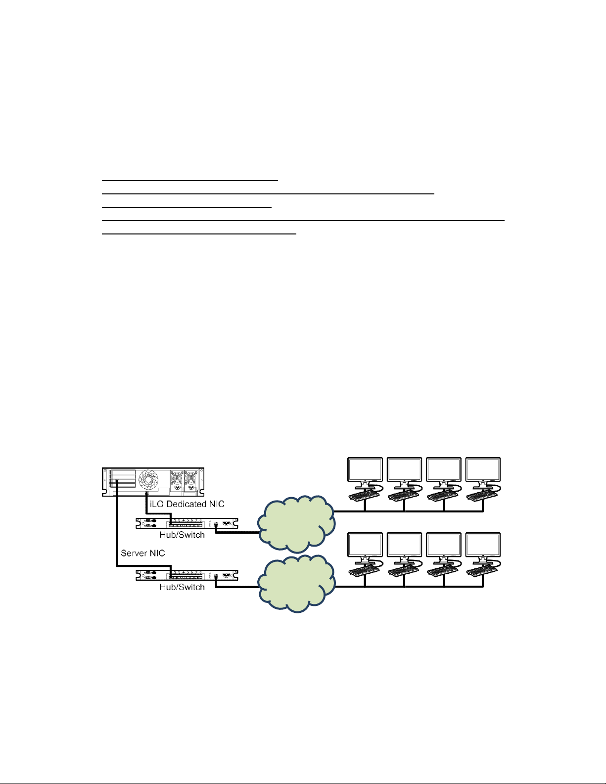
2. Setting up iLO
Express Server
Production
Network
Management
Network
Management Clients
Production Clients
Preparing to set up iLO
Before setting up an iLO management processor, you must decide how to handle networking
and security. The following questions can help you configure iLO:
Procedure
1. How will iLO connect to the network?
2. Will NIC Teaming be used with the Shared Network Port configuration?
3. How will iLO acquire an IP address?
4. What access security is required, and what user accounts and privileges are needed?
5. What tools will you use to configure iLO?
iLO network connection options
Typically, iLO is connected to the network through a dedicated management network or a shared
connection on the production network.
Dedicated management network
In this configuration, the iLO port is on a separate network. A separate network improves
performance and security because you can physically control which workstations are connected
to the network. A separate network also provides redundant access to the server when a
hardware failure occurs on the production network. In this configuration, iLO cannot be accessed
directly from the production network. The Dedicated management network is the preferred iLO
network configuration.
Figure 1: Dedicated management network
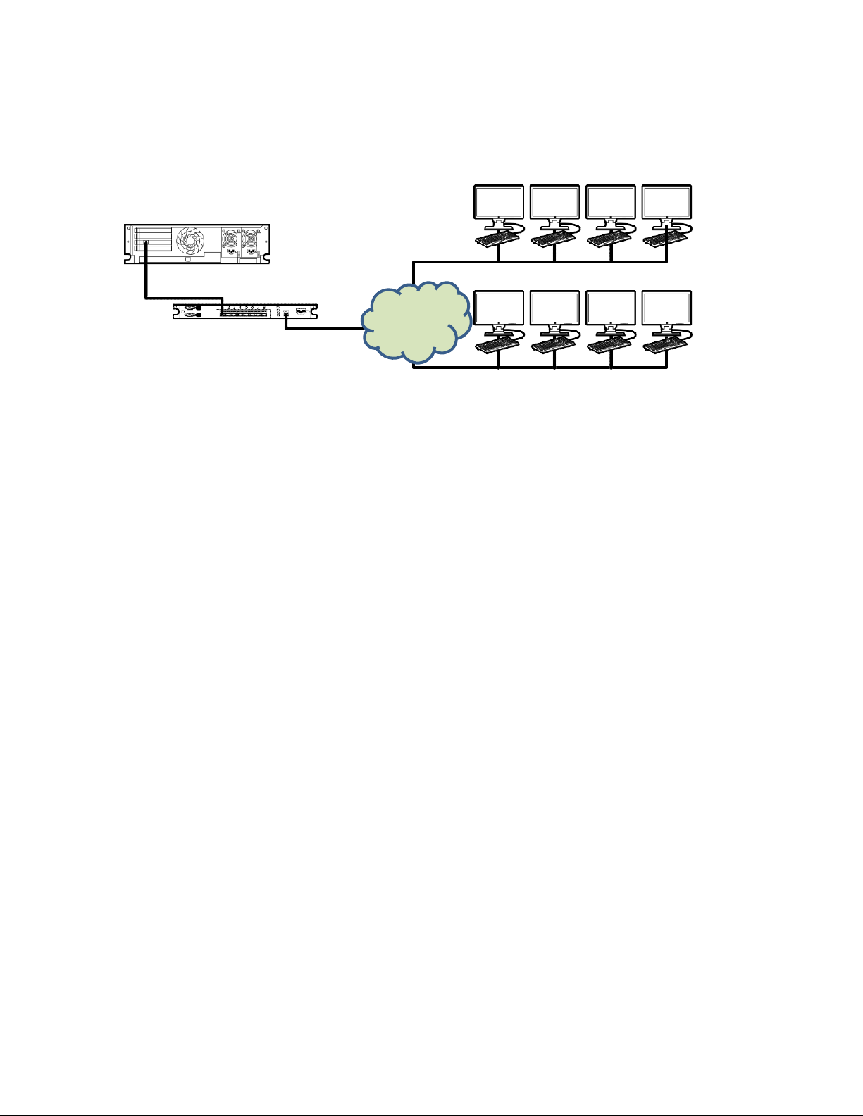
Production network
In this configuration, both the NIC and the iLO port are connected to the production network. In
iLO, this type of connection is called the Shared Network Port configuration. Certain NEC
Corporation embedded NICs and add-on cards provide this capability. This connection enables
access to iLO from anywhere on the network and reduces the amount of networking hardware
and infrastructure required to support iLO.
4
Page 11
Express Server
Server NIC/iLO Shared NIC
Management Clients
Hub/Switch
Management/
Production
Network
Production Clients
• There are some drawbacks to using this configuration.
• With a shared network connection, traffic can hinder iLO performance.
• During the server boot process and when the OS NIC drivers are loading and unloading, there
are brief periods of time (2–8 seconds) when iLO cannot be reached from the network. After
these short periods, iLO communication is restored and iLO will respond to network traffic.
Figure 2: Shared network connection
NIC teaming with Shared Network Port configurations
NIC teaming is a feature you can use to improve server NIC performance and reliability.
NIC teaming constraints
When you select a teaming mode to use when iLO is configured to use the Shared Network Port:
• iLO network communications will be blocked in the following conditions:
◦ The selected NIC teaming mode causes the switch that iLO is connected with to ignore
traffic from the server NIC/port that iLO is configured to share.
◦ The selected NIC teaming mode sends all traffic destined for iLO to a NIC/port other than
the one that iLO is configured to share.
• Because iLO and the server transmit and receive on the same switch port, the selected NIC
teaming mode must allow the switch to tolerate traffic with two different MAC addresses on
the same switch port. Some implementations of LACP (802.3ad) will not tolerate multiple MAC
addresses on the same link.
NIC teaming modes
If your server is configured to use NIC teaming, observe the following guidelines.
Network Fault Tolerance
5
The server transmits and receives on only one NIC (the primary adapter). The other NICs
(secondary adapters) that are part of the team do not transmit server traffic and they ignore
received traffic. This mode allows the iLO Shared Network Port to function correctly.
Select the NIC/port iLO uses as the Preferred Primary Adapter.
Page 12

Transmit Load Balancing
The server transmits on multiple adapters but receives only on the primary adapter. This mode
allows the iLO Shared Network Port to function correctly.
Select the NIC/port iLO uses as the Preferred Primary Adapter.
Switch Assisted Load Balancing
In this mode, there is no concept of primary and secondary adapters. All adapters are
considered equal for the purposes of sending and receiving data. This mode is the most
problematic for iLO Shared Network Port configurations because traffic destined for iLO can
be received on only one of the server NIC/ports. To determine the constraints that your switch
vendor places on their implementation of switch assisted load balancing, see the switch
vendor documentation.
iLO IP address acquisition
To enable iLO access after it is connected to the network, the iLO management processor must
acquire an IP address and subnet mask. You can use a dynamic address or a static address.
Dynamic IP address
A dynamic IP address is set by default. iLO obtains the IP address and subnet mask from DNS
or DHCP servers. This method is the simplest.
If you use DHCP:
• The iLO management port must be connected to a network that is connected to a DHCP
server, and iLO must be on the network before power is applied. DHCP sends a request
soon after power is applied. If the DHCP request is not answered when iLO first boots, it
will reissue the request at 90-second intervals.
• The DHCP server must be configured to provide DNS and WINS name resolution.
Static IP address
If DNS or DHCP servers are not available on the network, a static IP address is used. A static IP
address can be configured by using the BMC Configuration Utility.
If you plan to use a static IP address, you must have the IP address before starting the iLO
setup process.
iLO access security
You can use the following methods to manage access to iLO:
Local accounts
Up to 12 user accounts can be stored in iLO. This configuration is ideal for small environments
such as labs and small-sized or medium-sized businesses.
Login security with local accounts is managed through the iLO Access Settings and user
privileges.
6
Page 13

Directory services
Up to six directory groups can be configured in iLO. Use a directory to authenticate and
authorize iLO access. This configuration enables an unlimited number of users and easily scales
to the number of iLO devices in an enterprise.
If you plan to use directory services, consider enabling at least one local administrator account
for alternate access.
A directory provides a central point of administration for iLO devices and users, and the
directory can enforce a strong password policy.
iLO configuration tools
iLO supports various interfaces for configuration and operation. This guide discusses the
following interfaces:
iLO web interface
Use the iLO web interface when you can connect to iLO on the network by using a web
browser. You can also use this method to reconfigure an iLO management processor.
ROM-based setup
Use the BMC Configuration Utility when the system environment does not use DHCP, DNS, or
WINS. Other configuration options not discussed in this guide follow:
EXPRESSBUILDER
To start EXPRESSBUILDER, press F10 during POST.
iLO RESTful API
A management interface that server management tools can use to perform configuration,
inventory, and monitoring of a supported server through iLO.
Scripting
You can use scripting to set up multiple iLO management processors. You can use scripts to
configure iLO on the network during initial deployment or from a deployed host.
• SMASH CLP—A command-line protocol that can be used when a command line is
accessible through SSH or the physical serial port.
7
Page 14

Initial setup steps: Process overview
The iLO default settings enable you to use most features without additional configuration.
However, the configuration flexibility of iLO enables customization for multiple enterprise
environments. This chapter discusses the initial iLO setup steps.
Procedure
1. Connect iLO to the network.
2. If you are not using dynamic IP addressing, use the ROM-based setup utilities to configure a
static IP address.
3. If you will use the local accounts feature, use the ROM-based setup utilities to
configure user accounts.
4. Configure a time zone to iLO. iLO 5 Firmware Version 1.15 Aug 17 2017 needs a time zone
configuration to display a correct date and time.
5. Optional: Install an iLO license.
6. If necessary, install the iLO drivers.
Connecting iLO to the network
Connect iLO to the network through a production network or a dedicated management network.
iLO uses standard Ethernet cabling, which includes CAT 5 UTP with RJ-45 connectors. Straightthrough cabling is necessary for a hardware link to a standard Ethernet hub or switch.
For more information about setting up your hardware, see the server user guide.
More Information
iLO network connection options
Setting up iLO by using the BMC Configuration Utility
NEC Corporation recommends using the BMC Configuration Utility to set up iLO for the first time
and to configure iLO network parameters for environments that do not use DHCP, DNS, or WINS.
NOTE:
If you can connect to iLO on the network by using a web browser, you can also use the iLO
web interface to configure iLO. Access iLO from a remote network client by using a
supported browser and providing the default DNS name, user name, and password.
Configuring a static IP address (BMC Configuration Utility)
This step is required only if you want to use a static IP address. When you use dynamic IP
addressing, the DHCP server automatically assigns an IP address for iLO.
To simplify installation, NEC Corporation recommends using DNS or DHCP with iLO.
8
Page 15

Procedure
1. Optional: If you access the server remotely, start an iLO remote console session.
2. Restart or power on the server.
3. Press F9 in the server POST screen.
The UEFI System Utilities start.
4. Click System Configuration.
5. Click BMC Configuration Utility.
6. Disable DHCP:
a. Click Network Options.
b. Select OFF in the DHCP Enable menu.
The IP Address, Subnet Mask, and Gateway IP Address boxes become editable. When
DHCP Enable is set to ON, you cannot edit these values.
7. Enter values in the IP Address, Subnet Mask, and Gateway IP Address boxes.
8. To save the changes and exit, press F12.
9. The BMC Configuration Utility prompts you to confirm that you want to save the pending
configuration changes.
10. To save and exit, click Yes - Save Changes.
11. The BMC Configuration Utility notifies you that iLO must be reset in order for the changes to
take effect.
12. Click OK.
iLO resets, and the iLO session is automatically ended. You can reconnect in approximately
30 seconds.
13. Resume the normal boot process:
a. Start the iLO remote console.
The BMC Configuration Utility is still open from the previous session.
b. Press ESC several times to navigate to the System Configuration page.
c. To exit the System Utilities and resume the normal boot process, click Exit and resume
system boot.
Managing local user accounts with the BMC Configuration Utility
Adding user accounts (BMC Configuration Utility)
Procedure
1. Optional: If you access the server remotely, start an iLO remote console session.
9
Page 16

2. Restart or power on the server.
3. Press F9 in the server POST screen.
The UEFI System Utilities start.
4. Click System Configuration, click BMC Configuration Utility, click User Management, and then
click Add User.
5. Select the privileges for the new user.
To assign a privilege, select YES in the menu next to the privilege name. To remove a
privilege, select NO.
The Login privilege is assigned to every user by default, so it is not listed in the BMC
Configuration Utility.
You cannot assign the Recovery Set privilege through the BMC Configuration Utility, so it is
not available in the list.
6. Enter the user name and login name in the New User Name and Login Name boxes.
7. Enter the password.
a. Move the cursor to the Password box, and then press Enter.
The Enter your new password box opens.
b. Type the password, and then press Enter.
The Confirm your new password box opens.
c. Type the password again to confirm, and then press Enter.
8. The BMC Configuration Utility confirms the new account creation.
9. To close the confirmation dialog box, click OK.
10. Create as many user accounts as needed, and then press F12 to save the changes and exit
the system utilities.
11. When prompted to confirm the changes, click Yes - Save Changes to exit the utility and
resume the boot process.
More Information
iLO user privileges
iLO user account options
Editing user accounts (BMC Configuration Utility)
Procedure
1. Optional: If you access the server remotely, start an iLO remote console session.
2. Restart or power on the server.
3. Press F9 in the server POST screen.
10
Page 17

The UEFI System Utilities start.
4. Click System Configuration, click BMC Configuration Utility, click User Management, and
then click Edit/Remove User.
5. In the Action menu for the user you want to edit or remove, select Edit.
The account properties are displayed.
6. Update the Login Name.
7. Update the Password.
a. Move the cursor to the Password box, and then press Enter.
The Enter your new password box opens.
b. Type the password, and then press Enter.
The Confirm your new password box opens.
c. Type the password again to confirm, and then press Enter.
8. Modify the user account privileges.
To assign a privilege, select YES in the menu next to the privilege name. To remove a
privilege, select NO.
The Login privilege is assigned to every user by default, so it is not available in the BMC
Configuration Utility.
You cannot assign the Recovery Set privilege through the BMC Configuration Utility, so it is
not available in the list.
9. Update as many user accounts as needed, and then press F12 to save the changes and exit
the system utilities.
10. When prompted to confirm the changes, click Yes - Save Changes to exit the utility and
resume the boot process.
More Information
iLO user privileges
iLO user account options
Removing user accounts (BMC Configuration Utility)
Procedure
1. Optional: If you access the server remotely, start an iLO remote console session.
2. Restart or power on the server.
3. Press F9 in the server POST screen.
The System Utilities start.
4. Click System Configuration, click BMC Configuration Utility, click User Management, and then
11
Page 18

click Edit/Remove User.
5. In the Action menu for the user you want to remove, select Delete.
The user name is marked to be deleted when you save the changes on this page.
6. If needed, mark other user accounts to delete, and then press F12 to save the changes and
exit the system utilities.
7. When prompted to confirm the changes, click Yes - Save Changes to exit the utility and
resume the boot process.
Logging in to iLO for the first time
Procedure
1. Enter https://<iLO hostname or IP address>.
HTTPS (HTTP exchanged over an SSL encrypted session) is required for accessing the iLO
web interface.
2. Enter the default user credentials, and then click Log In.
iLO default credentials
The iLO firmware is configured with a default user name, password, and DNS name. The default
information is on the serial label pull tab attached to the server that contains the iLO
management processor. Use these values to access iLO remotely from a network client by using
a web browser.
• User name—Administrator
• Password—A random eight-character string
• DNS name—BMCXXXXXXXXXXXX, where the X characters represent the server serial
number.
IMPORTANT:
NEC Corporation recommends changing the default password after you log in to iLO for
the first time.
If you reset iLO to the factory default settings, use the default iLO account credentials to
log in after the reset.
iLO licensed features
iLO (Standard) is preconfigured on Express servers without an additional cost or license.
Features that enhance productivity are licensed.
To activate iLO licensed features, install an iLO license.
12
Page 19

iLO drivers
iLO is an independent microprocessor running an embedded operating system. The architecture
ensures that most iLO functionality is available, regardless of the host operating system. The iLO
driver enables software such as the Agentless Management Service to communicate with iLO.
The installed OS and system configuration determine the installation requirements.
The iLO drivers will be applied automatically when you install using EXPRESSBUILDER and Starter
Pack.
iLO time zone
Configure time zone to iLO . Login to iLO Web Interface using an user has Configure iLO Settings
privilege. Click iLO Dedicated Network Port and Click SNTP when iLO is using iLO Dedicated
Network Port. Click iLO Shared Network Port and Click SNTP when iLO is using iLO Shared
Network Port.
If you would like to sync a date and time between iLO and SNTP server, configure iLO SNTP
settings.
If you won’t use time syncing function with SNTP server, configure following parameters.
Use DHCPv4 Supplied Time Settings – Disable
Use DHCPv6 Supplied Time Settings – Disable
Primary Time Server – Blank
Secondary Time Server – Blank
Time Zone – Refer next page.
IMPORTANT:
The Time Zone setting is required to display correct time by iLO5 Firmware Version 1.15 Aug 17
2017 even granting that you won’t use time syncing function with SNTP server.
13
Page 20
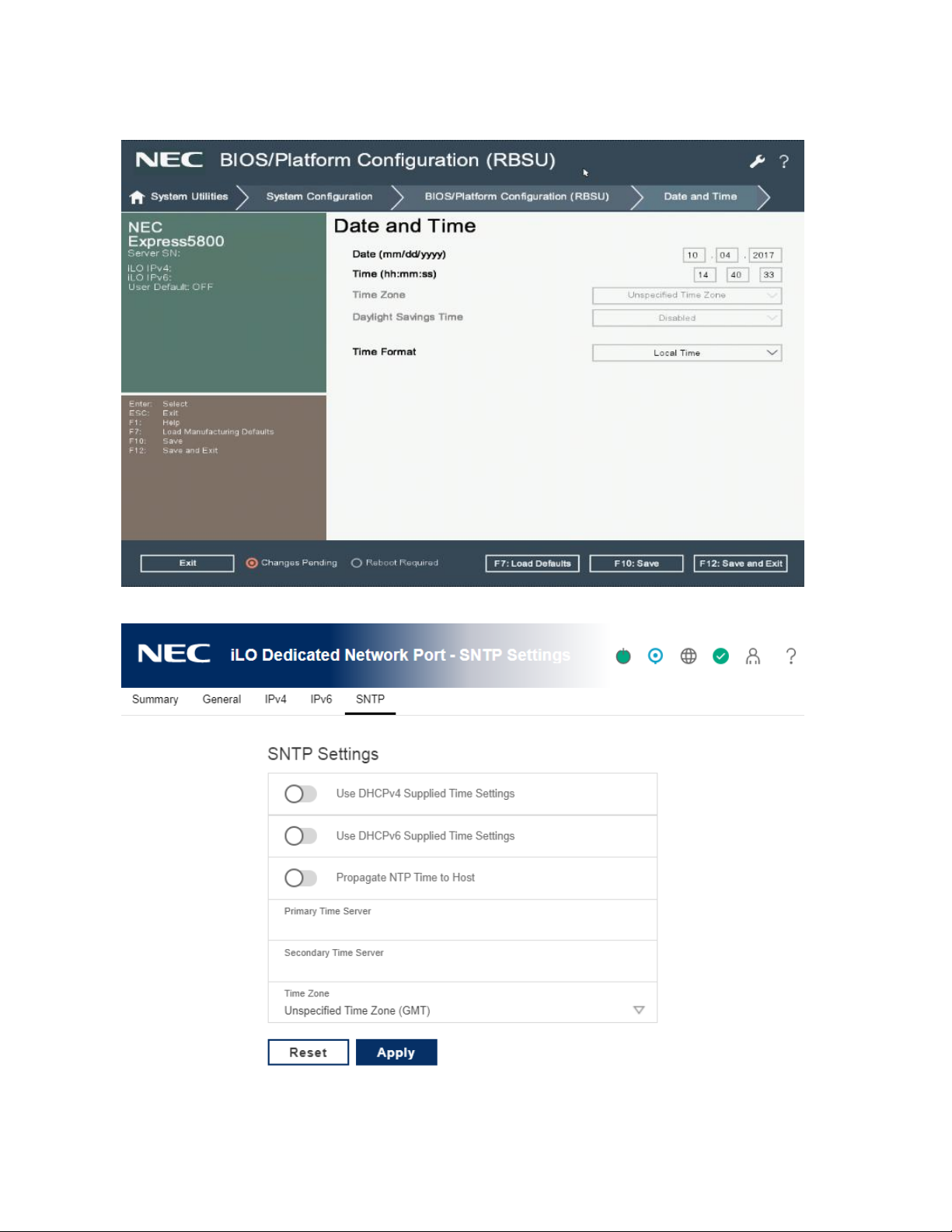
If Time Format on BIOS/Platform Configuration(RBSU) is Local time, set Unspecified Time Zone
(GMT) to iLO Time Zone.
BIOS/Platform Configuration(RBSU) :
iLO Web Interface:
14
Page 21
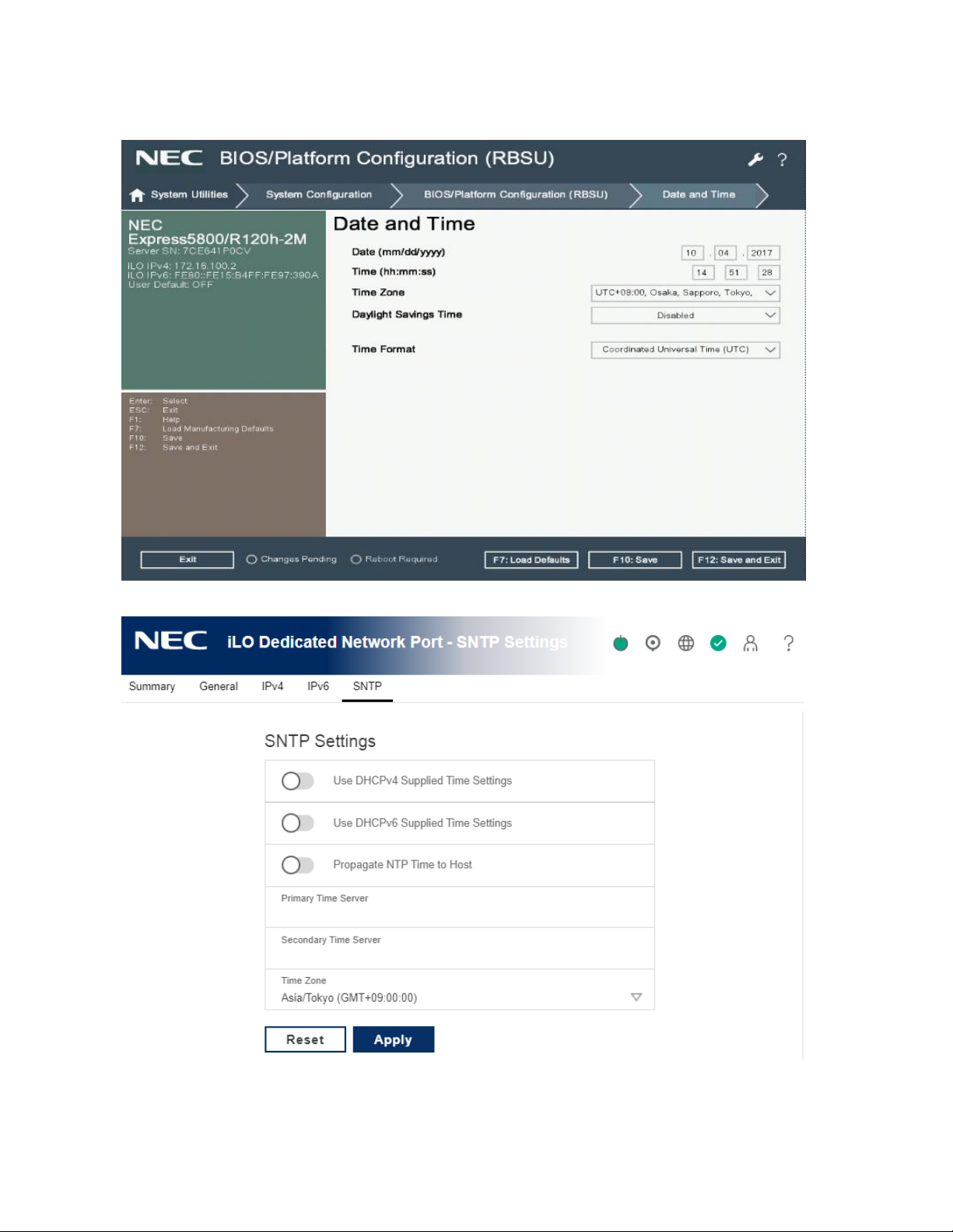
If Time Format on BIOS/Platform Configuration(RBSU) is Coordinated Universal Time (UTC), set same
time zone parameter to iLO Time Zone.
BIOS/Platform Configuration(RBSU) :
iLO Web Interface:
After setting, Click Apply and Click Reset. iLO will restart to apply the settings.
15
Page 22

3. Using the iLO web interface
iLO web interface
You can use the iLO web interface to manage iLO. You can also use a Remote Console, SMASH
CLP, or the iLO RESTful API.
Supported browsers
iLO 5 supports the latest versions of the following browsers:
• Microsoft Edge
• Mozilla Firefox
• Google Chrome mobile and desktop
• Microsoft Internet Explorer 11
Browser requirements
The iLO web interface requires a browser that meets the following requirements:
• JavaScript—The iLO web interface uses client-side JavaScript extensively.
This setting is not enabled by default in all versions of Internet Explorer. To check or change
this setting, see Configuring the Internet Explorer JavaScript setting.
• Cookies—Cookies must be enabled for certain features to function correctly.
• Pop-up windows—Pop-up windows must be enabled for certain features to function
correctly. Verify that pop-up blockers are disabled.
• TLS—To access the iLO web interface, you must enable TLS 1.0 or later in your browser.
Configuring the Internet Explorer JavaScript setting
Some versions of Internet Explorer have JavaScript disabled by default. Use the following
procedure to enable JavaScript.
Procedure
1. Start Internet Explorer.
2. Select Tools > Internet options.
3. Click Security.
4. Click Custom level.
5. In the Scripting section, set Active scripting to Enable.
6. Click OK.
7. Refresh your browser window.
16
Page 23

Logging in to the iLO web interface
Procedure
1. Enter https://<iLO host name or IP address>.
When you access the iLO web interface, you must use HTTPS (HTTP exchanged over an SSL
encrypted session).
The iLO login page opens. If a login security banner is configured, the banner text is displayed in
the NOTICE section.
2. Do one of the following:
• On the login page, enter a directory or local user account name and password, and then
click Log In.
• Click the Zero Sign In button.
If iLO is configured for Kerberos network authentication, the Zero Sign In button is
displayed below the Log In button. You can use the Zero Sign In button to log in
without entering a user name and password.
More Information
iLO default credentials
Cookie sharing between browser instances and iLO
When you browse to iLO and log in, one session cookie is shared with all open browser windows
that share the iLO URL in the browser address bar. As a consequence, all open browser windows
share one user session. Logging out in one window ends the user session in all the open
windows. Logging in as a different user in a new window replaces the session in the other
windows.
This behavior is typical of browsers. iLO does not support multiple users logged in from two
different browser windows in the same browser on the same client.
Shared instances
When the iLO web interface opens another browser window or tab (for example, a help file), this
window shares the connection to iLO and the session cookie.
When you are logged into the iLO web interface, and you open a new browser window manually,
a duplicate instance of the original browser window opens. If the domain name in the address
bar matches the original browser session, the new instance shares a session cookie with the
original browser window.
Cookie order
During login, the login page builds a browser session cookie that links the window to the
appropriate session in the iLO firmware. The firmware tracks browser logins as separate sessions
17
Page 24

listed on the Session List page.
For example, when User1 logs in, the web server builds the initial frames view, with User1 listed
as the active user, menu items in the navigation pane, and page data in the right pane. When
User1 clicks from link to link, only the menu items and page data are updated.
While User1 is logged in, if User2 opens a browser window on the same client and logs in, the
second login overwrites the cookie generated in the User1 session. Assuming that User2 is a
different user account, a different current frame is built, and a new session is granted. The
second session appears on the Session List page as User2.
The second login has effectively orphaned the first session by overriding the cookie generated
during the User1 login. This behavior is the same as closing the User1 browser without clicking
the Log Out button. The User1 orphaned session is reclaimed when the session timeout expires.
Because the current user frame is not refreshed unless the browser is forced to refresh the entire
page, User1 can continue navigating by using the browser window. However, the browser is now
operating by using the User2 session cookie settings, even though it might not be readily
apparent.
If User1 continues to navigate in this mode (User1 and User2 sharing a process because User2
logged in and reset the session cookie), the following might occur:
• User1 session behaves consistently with the privileges assigned to User2.
• User1 activity keeps User2 session alive, but User1 session can time out unexpectedly.
• Logging out of either window causes both sessions to end. The next activity in the other
window can redirect the user to the login page as if a session timeout or premature timeout
occurred.
• Clicking Log Out from the second session (User2) results in the following warning message:
Logging out: unknown page to display before redirecting the user to the
login page.
• If User2 logs out and then logs back in as User3, User1 assumes the User3 session.
• If User1 is at login, and User2 is logged in, User1 can alter the URL to redirect to the index
page. It appears as if User1 has accessed iLO without logging in.
These behaviors continue as long as the duplicate windows are open. All activities are attributed
to the same user, using the last session cookie set.
Displaying the current session cookie
After logging in, you can force the browser to display the current session cookie by entering the
following in the URL navigation bar:
javascript:alert(document.cookie)
The first field visible is the session ID. If the session ID is the same among the different browser
18
Page 25
windows, these windows are sharing iLO session.
You can force the browser to refresh and reveal your true identity by pressing F5, selecting View >
Refresh, or clicking the Refresh button.
Best practices for preventing cookie-related issues
• Start a new browser for each login by double-clicking the browser icon or shortcut.
• To close an iLO session before you close the browser window, click the Log Out button.
iLO web interface
The iLO web interface groups similar tasks for easy navigation and workflow. The interface is
organized with a navigation tree in the left pane. To use the web interface, click an item in the
navigation tree, and then click the name of the tab you want to view.
Using the iLO controls
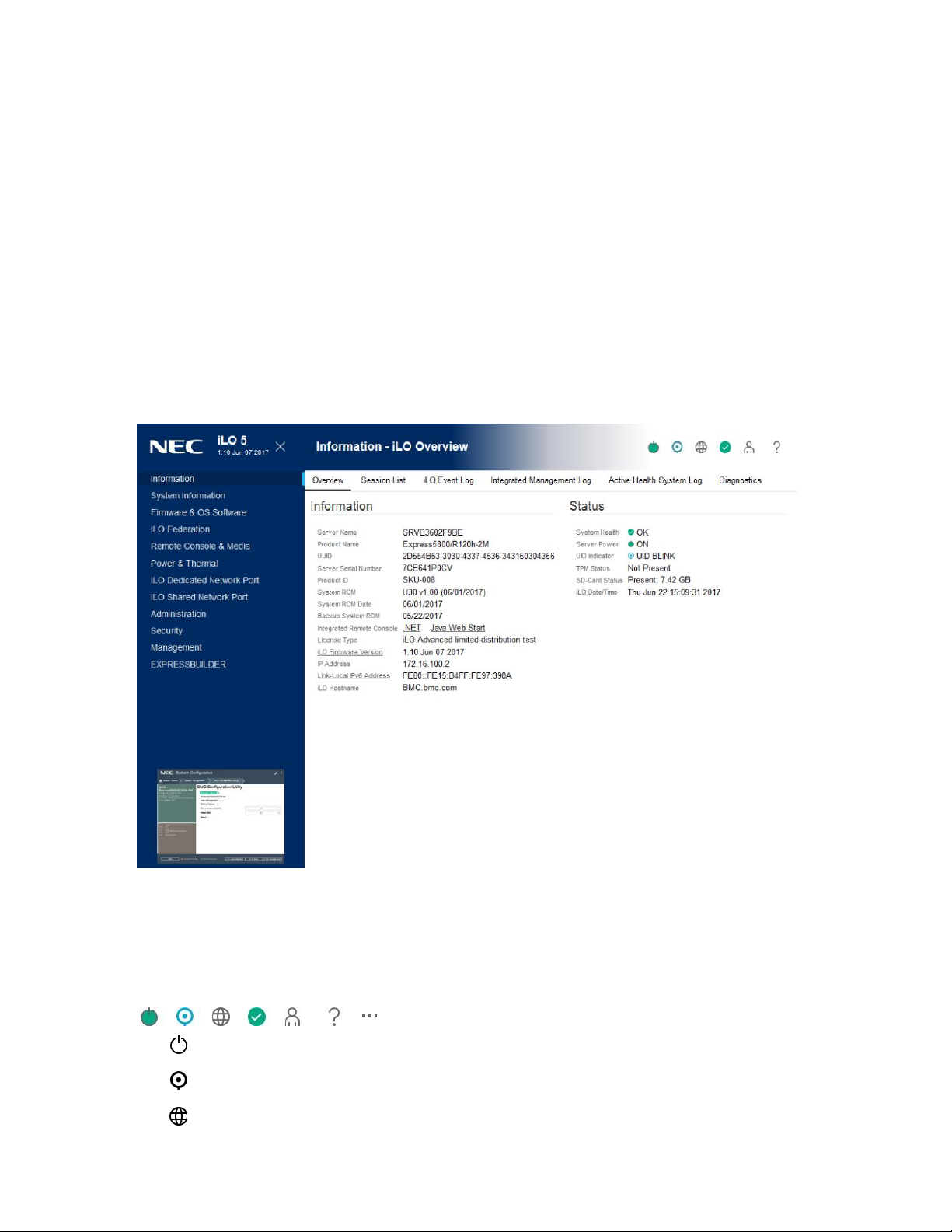
iLO control icons
When you log in to the iLO web interface, the iLO controls are available from any iLO page.
• Power icon—Click this icon to access the Virtual Power Button features.
• UID icon—Click this icon to turn the UID LED on and off.
• Language—Click this icon to select a language for the current iLO web interface session.
19
Page 26

• To view or modify the language settings, click the language icon, and then select Settings.
• Health icon—Click this icon to view the overall health status for the server fans,
temperature sensors, and other monitored subsystems. For all components except the
Agentless Management Service (AMS), click a component to view additional details.
• User icon—Click this icon to do the following:
◦ To log out of the current iLO web interface session, click the user icon, and then select
Logout.
◦ To view the active iLO sessions, click the user icon, and then select Sessions.
◦ To view or modify iLO user accounts, click the user icon, and then select Settings.
• Help icon—Click this icon to view online help for the current iLO web interface page.
• Ellipsis icon—This icon is displayed on the Firmware & OS Software page when the browser
window is too small to show the full page. To access the Update Firmware and Upload to iLO
Repository options, click this icon. These options are available on all Firmware & OS Software
tabs.
iLO navigation pane
iLO has a collapsible navigation pane that is accessible from each page.
• To toggle between showing and hiding the navigation pane, click the icon in the top left
corner of the iLO web interface.
• To hide the navigation pane, click the X icon.
• To show the navigation pane, click the icon in the top left corner of the iLO web interface.
• The navigation pane shows a thumbnail of the Remote Console. To start a Remote Console,
click the thumbnail and select a console option from the menu.
• For servers with monitors, click the Remote Console thumbnail in the navigation pane, and
then select Wake-Up Monitor to wake up a monitor that is in sleep mode.
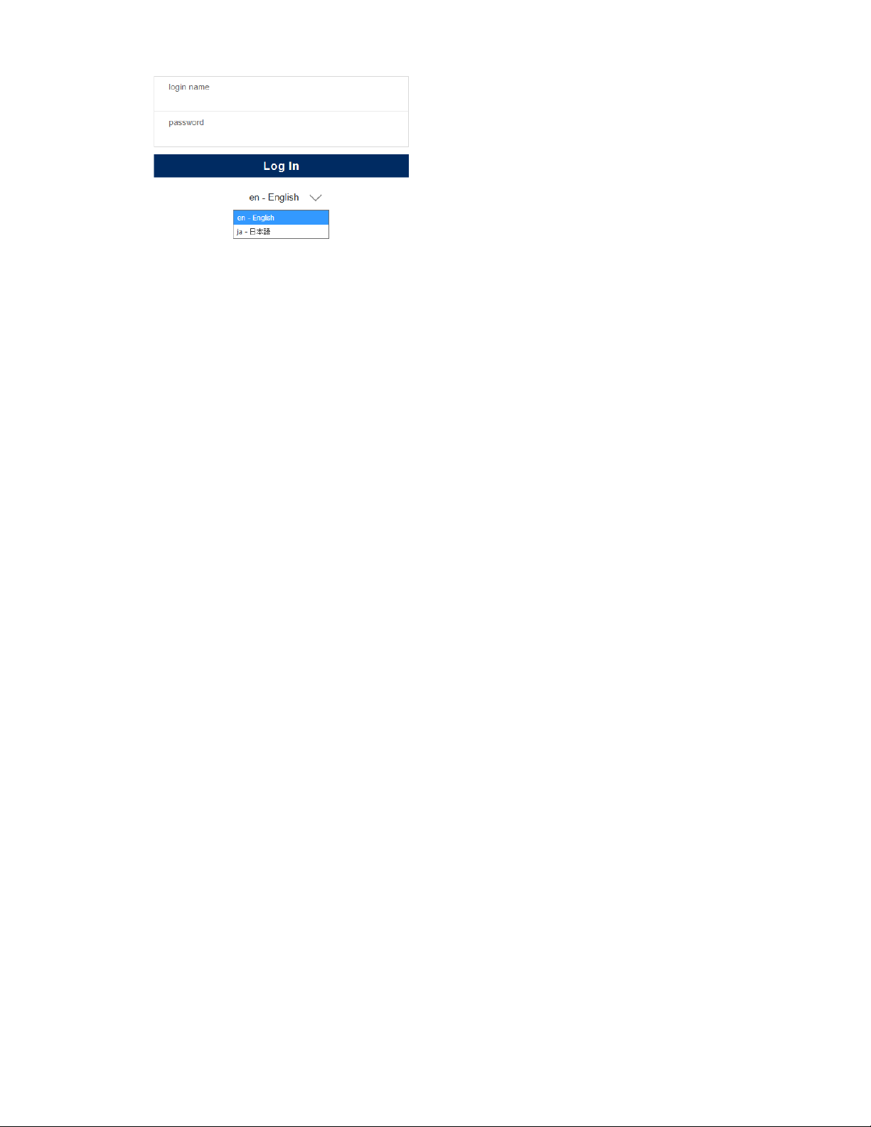
Changing the language from the login page
If a language pack is installed, use the language menu on the login screen to select the language
for the iLO session. This selection is saved in a browser cookie for future use.
Prerequisites
Procedure
A language pack is installed.
1. Navigate to the iLO Login page.
2. Select a language from the Language menu.
20
Page 27
21
Page 28
4. Viewing iLO information and logs
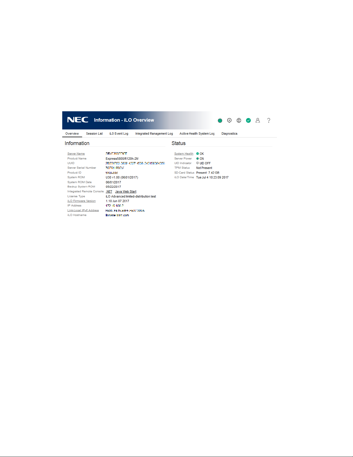
Viewing iLO overview information
Procedure
1. Navigate to the Information page.
The iLO Overview page displays high-level details about the server and the iLO subsystem,
as well as links to commonly used features.
System information details
• Server Name—The server name defined by the host operating system. To navigate to the
Access Settings page, click the Server Name link.
• Product Name—The product with which this iLO processor is integrated.
• UUID—The universally unique identifier that software uses to identify this host. This value is
assigned when the system is manufactured.
• UUID (Logical)—The system UUID that is presented to host applications. This value is
displayed only when set by other software. This value might affect operating system and
application licensing. The UUID (Logical) value is set as part of the logical server profile that
is assigned to the system. If the logical server profile is removed, the system UUID value
reverts from the UUID (Logical) value to the UUID value. If no UUID (Logical) value is set,
this item is not displayed.
• Server Serial Number —The server serial number, which is assigned when the system is
manufactured. You can change this value by using the ROM-based system utilities during
POST.
• Serial Number (Logical)—The system serial number that is presented to host applications.
This value is displayed only when set by other software. This value might affect operating
system and application licensing. The Serial Number (Logical) value is set as part of the
22
Page 29

logical server profile that is assigned to the system. If the logical server profile is removed,
the serial number value reverts from the Serial Number (Logical) value to the Server Serial
Number value. If no Serial Number (Logical) value is set, this item is not displayed.
• Chassis Serial Number—The serial number of the chassis that contains the server node.
• Product ID—This value distinguishes between different systems with similar serial numbers.
The product ID is assigned when the system is manufactured. You can change this value by
using the UEFI system utilities during POST.
• System ROM—The version of the active system ROM.
• System ROM Date—The date of the active system ROM.
• Backup System ROM—The version of the backup system ROM. If a system ROM update
fails or is rolled back, the backup system ROM is used. This value is displayed only if the
system supports a backup system ROM.
• Integrated Remote Console—Provides links to start the .NET IRC or Java IRC for remote,
out-of- band communication with the server console.
For information about the available remote console options, see iLO Integrated Remote
Console.
• License Type—The level of licensed iLO firmware functionality.
• iLO Firmware Version—The version and date of the installed iLO firmware. To navigate to
the Firmware Update page, click the iLO Firmware Version link.
• IP Address—The network IP address of the iLO subsystem.
• Link-Local IPv6 Address—The SLAAC link-local address of the iLO subsystem. To navigate
to the Network Summary page, click the Link-Local IPv6 Address link. This value is
displayed only for iLO Dedicated Network Port configurations.
• iLO Hostname—The fully qualified network name assigned to the iLO subsystem. By
default, the hostname is BMC, followed by the system serial number and the current domain
name. This value is used for the network name and must be unique.
System status details
• System Health—The server health indicator. This value summarizes the condition of the
monitored subsystems, including overall status and redundancy (ability to handle a failure).
Lack of redundancy in any subsystem at startup will not degrade the system health status. To
navigate to the Health Summary page, click the System Health link.
• Server Power—The server power state (ON or OFF). To access the Virtual Power Button
features, click the Server Power icon.
• UID Indicator—The state of the UID LED. The UID LED helps you identify and locate a server,
especially in high-density rack environments. The possible states are UID ON, UID OFF, and
UID BLINK.
23
Page 30

If the iLO Service Port is in use, UID BLINK status includes the Service Port status. The
possible values are UID BLINK (Service Port Busy), UID BLINK (Service Port Error), and
UID BLINK (Service Port Finished).
To turn the UID LED on or off, click the UID Indicator icon, click the UID control at the top of
the iLO web interface window, or use the UID buttons on the server chassis.
When the UID is blinking, and then it stops blinking, the status reverts to the previous value
(UID ON or UID OFF). If a new state is selected while the UID LED is blinking, that state takes
effect when the UID LED stops blinking.
CAUTION:
The UID LED blinks automatically to indicate that a critical operation is underway on the
host, such as Remote Console access or a firmware update. Do not remove power from
a server when the UID LED is blinking.
• TPM Status or TM Status—The status of the TPM or TM socket or module. The possible
values are Not Supported, Not Present, or Present-Enabled.
Trusted Platform Modules and Trusted Modules are computer chips that securely store
artifacts used to authenticate the platform. These artifacts can include passwords,
certificates, or encryption keys. You can also use a TPM or TM to store platform
measurements to make sure that the platform remains trustworthy.
On a supported system, ROM decodes the TPM or TM record and passes the configuration
status to iLO, the iLO RESTful API, and the CLP.
• Module Type—The TPM or TM type and specification version. The possible values are TPM
1.2, TPM 2.0, TM 1.0, TPM Module 2.0 (Intel PTT), Not Specified, and Not Supported.
This value is displayed when a TPM or TM is present on a server.
• SD-Card Status—The status of the internal SD card. If present, the number of blocks in the
SD card is displayed.
• Access Panel Status—The state of the access panel. The possible states are OK (the access
panel is installed) and Intrusion (the access panel is open). This value is displayed only on
servers that are configured for chassis intrusion detection.
• iLO Date/Time—The internal clock of the iLO subsystem.
24
Page 31

Managing iLO sessions
Prerequisites
Administer User Accounts privilege
Procedure
1. Navigate to the Information page, and then click the Session List tab. The Session List
page displays information about the active iLO sessions.
2. Optional: To disconnect one or more sessions, click the check box next to each session you
want to disconnect, and then click Disconnect Session.
Session list details
iLO displays the following details in the Current Session and Session List tables:
• User—The iLO user account name.
• IP—The IP address of the computer used to log in to iLO.
• Login Time—The date and time that the iLO session started.
• Access Time—The date and time that iLO was last active in the session.
• Expires—The date and time that the session will end automatically.
• Source—The session source (for example, Remote Console, web interface, ROM-based
setup utility, iLO RESTful API, or SSH).
• Privilege icons (current user only)—The privileges assigned to the current user account.
25
Page 32
iLO Event Log
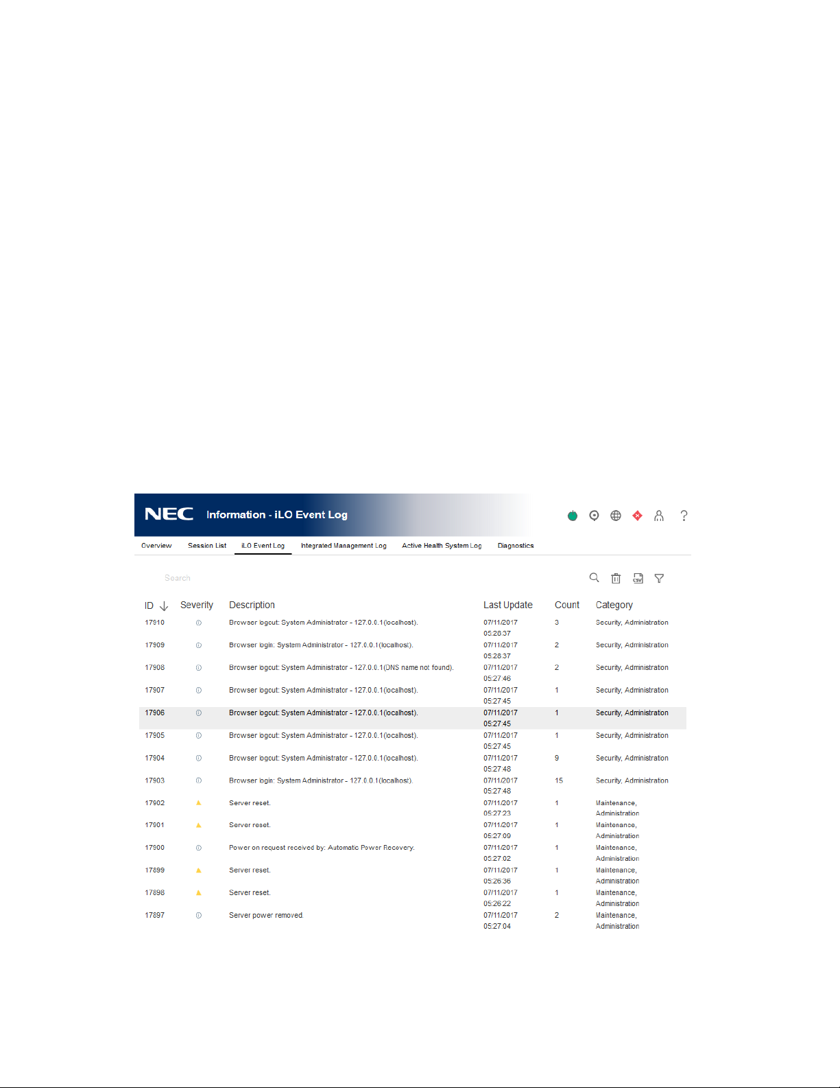
The event log provides a record of significant events recorded by the iLO firmware.
Logged events include major server events such as a server power outage or a server reset, and
iLO events such as unauthorized login attempts. Other logged events include successful or
unsuccessful browser and Remote Console logins, virtual power and power-cycle events, clearing
the log, and some configuration changes, such as creating or deleting a user.
iLO provides secure password encryption, tracking all login attempts and maintaining a record of
all login failures. The Authentication Failure Logging setting allows you to configure logging
criteria for failed authentications. The event log captures the client name for each logged entry
to improve auditing capabilities in DHCP environments, and records the account name,
computer name, and IP address.
Viewing the event log
Procedure
1. Click Information in the navigation tree, and then click the iLO Event Log tab.
2. Optional: Use the event log sort, search, and filter features to customize the log view.
3. Optional: To view the event details pane, click an event.
Event log details
• ID—The event ID number. Events are numbered in the order in which they are generated. By
26
Page 33

default, the event log is sorted by the ID, with the most recent event at the top.
• Severity—The importance of the detected event.
• Description—The description identifies the component and detailed characteristics of the
recorded event. If the iLO firmware is rolled back to an earlier version, the description
UNKNOWN EVENT TYPE might be displayed for events recorded by the newer firmware. You
can resolve this issue by updating the firmware to the latest supported version, or by
clearing the event log.
• Last Update—The date and time when the latest event of this type occurred. This value is
based on the date and time stored by the iLO firmware.
If the iLO firmware did not recognize the date and time when an event was updated, [NOT
SET] is displayed.
• Count—The number of times this event has occurred (if supported).
In general, important events generate an event log entry each time they occur. They are not
consolidated into one event log entry.
When less important events are repeated, they are consolidated into one event log entry,
and the Count and Last Update values are updated. Each event type has a specific time
interval that determines whether repeated events are consolidated or a new event is logged.
• Category—The event category.
Event log icons
iLO uses the following icons to indicate event severity:
• Critical—The event indicates a service loss or imminent service loss. Immediate attention is
needed.
• Caution—The event is significant but does not indicate performance degradation.
• Informational—The event provides background information.
• Unknown—The event severity could not be determined.
Event log event pane details
• Initial Update—The date and time when the first event of this type occurred. This value is
based on the date and time stored by the iLO firmware.
If iLO did not recognize the date and time when the event was first created, [NOT SET] is
displayed.
• Event Code—A unique identifier for an event within a given event class displayed in
hexadecimal format.
27
Page 34

Customizing the event log view
Sorting events
Click a column heading to sort the event log table by that column.
To change the display to ascending or descending order, click the column heading again.
Event filters
To access the event log filters, click .
• To filter by severity, select a severity level from the Severity menu.
• To filter by event category, select a value in the Category menu.
• To change the displayed date and time for events, select a value in the Time menu. Choose
from the following:
◦ Show Default—Display UTC time.
◦ Show Local Time—Display the iLO web interface client time.
◦ Show ISO Time—Display UTC time in ISO 8601 format.
In iLO 5 Firmware Version 1.10 Jun 07 2017, when SNTP setting is not configured or when it
is not used in an environment where can be synchronized with the time server, the following
times are displayed.
If Show Default and Show ISO Time are selected, the following is displayed.
System time(UTC±Time Zone) displayed in BIOS/Platform Configuration(RBSU)
If Show Local Time is selected, the following is displayed.
Added to the System time(UTC±Time Zone) displayed in BIOS/Platform
Configuration(RBSU) and the time zone of the environment of the client connected to
iLO.
In iLO 5 Firmware Version 1.15 Aug 17 2017, when SNTP setting is not configured and Time
Format on BIOS/Platform Configuration(RBSU) is Local Time, the following times are
displayed.
If Show Default and Show ISO Time are selected, the following is displayed.
System time(UTC±Time Zone) displayed in BIOS/Platform Configuration(RBSU)
If Show Local Time is selected, the following is displayed.
Added to the System time(UTC±Time Zone) displayed in BIOS/Platform
Configuration(RBSU) and the time zone of the environment of the client connected to
iLO.
• To filter by the last update date, select a value in the Last Update menu.
Based on the time displayed in Show Default, the filter will be applied.
• To set the filters back to the default values, click Reset filters.
28
Page 35
Searching for an event
To search for events based on dates, event ID, or description text, click , and then enter text in
the search box.
Saving the event log to a CSV file
Use a supported browser to export the event log to a CSV file.
Procedure
1. Click Information in the navigation tree, and then click the iLO Event Log tab.
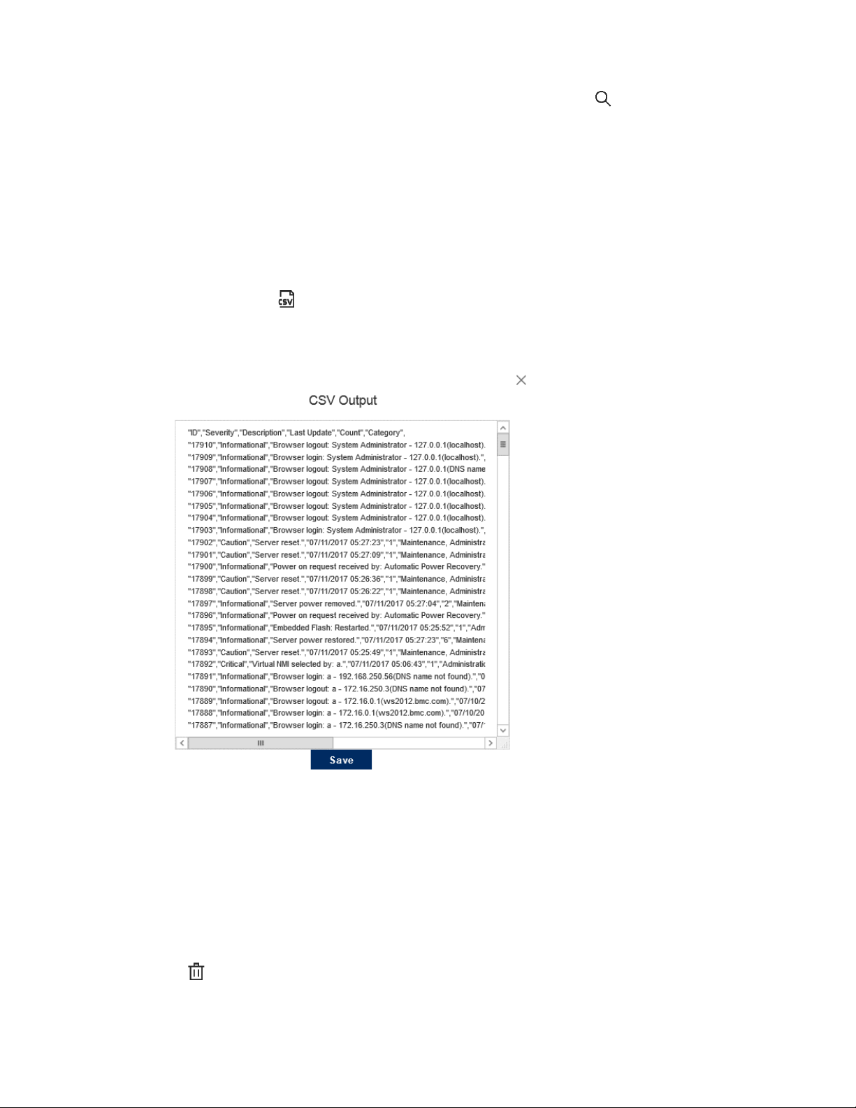
2. Click the CSV icon
3. In the CSV Output window, click Save, and then follow the browser prompts to save or open
the file.
Clearing the event log
Prerequisites
Configure iLO Settings privilege
Procedure
1. Click Information in the navigation tree, and then click the iLO Event Log tab.
2. Click .
3. When prompted to confirm the request, click OK.
29
Page 36

The event log is cleared of all previously logged information and an event is recorded in the log.
30
Page 37

Integrated Management Log
The IML provides a record of historical events that have occurred on the server. Events are
generated by the system ROM and by services such as the iLO driver. Logged events include all
server-specific events recorded by the iLO driver, including operating system information and
ROM-based POST codes.
Entries in the IML can help you diagnose issues or identify potential issues. Preventative action
might help to avoid disruption of service.
iLO manages the IML, which you can access through a supported browser, even when the server
is off. The ability to view the log when the server is off can be helpful when troubleshooting
remote host server issues.
Examples of the types of information recorded in the IML follow:
• Fan inserted
• Fan removed
• Fan failure
• Fan degraded
• Fan repaired
• Fan redundancy lost
• Fans redundant
• Power supply inserted
• Power supply removed
• Power supply failure
• Power supplies redundancy lost
• Power supplies redundant
• Temperature over threshold
• Temperature normal
• Automatic shutdown started
• Automatic shutdown canceled
• Drive failure
Viewing the IML
Procedure
1. Click Information in the navigation tree, and then click the Integrated Management Log
tab.
2. Optional: Use the IML sort, search, and filter features to customize the log view.
3. Optional: To view the event details pane, click an event.
31
Page 38
IML details
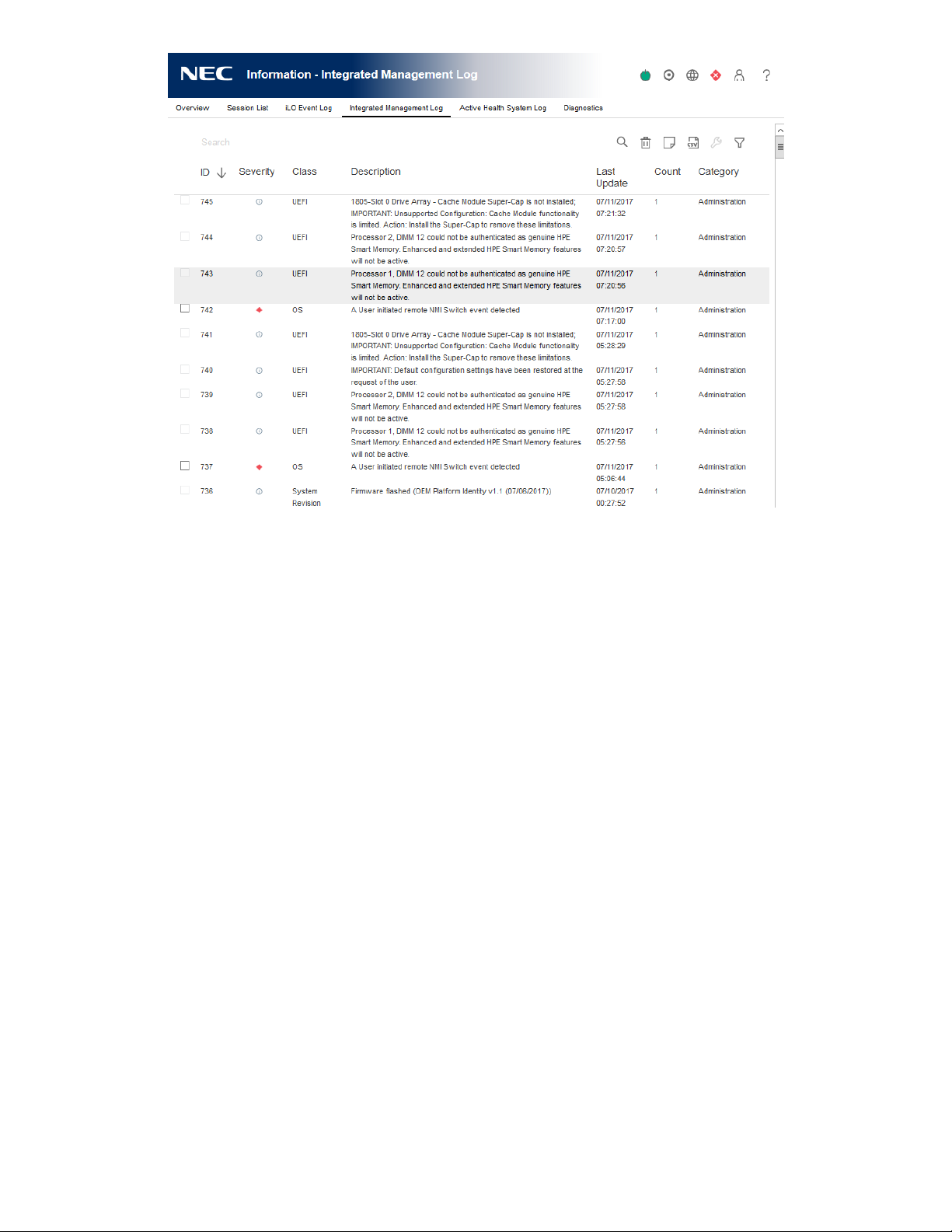
• The first column on the left side of the web interface displays an active check box next to
each event with Critical or Caution status. Use this check box to select an event to mark as
repaired.
• ID—The event ID number. Events are numbered in the order in which they are generated.
By default, the IML is sorted by the ID, with the most recent event at the top. A factory reset
will reset the counter.
• Severity—The importance of the detected event.
• Class—Identifies the type of event that occurred, for example, network, maintenance, or
system revision.
• Description—The description identifies the component and detailed characteristics of the
recorded event.
If the iLO firmware is rolled back, the description UNKNOWN EVENT TYPE might be
displayed for events recorded by the newer firmware. You can resolve this issue by updating
the firmware to the latest supported version, or by clearing the log.
• Last Update—The date and time when the latest event of this type occurred. This value is
based on the date and time stored by the iLO firmware.
If iLO did not recognize the date and time when an event was updated, [NOT SET] is
displayed.
• Count—The number of times this event has occurred (if supported).
32
Page 39

• Category—The event category. For example, Hardware Failure, Firmware Failure, Power, or
IML icons
iLO uses the following icons to indicate IML event severity:
• Critical—The event indicates a service loss or an imminent service loss. Immediate attention
• Caution—The event is significant but does not indicate performance degradation.
• Informational—The event provides background information.
In general, important events generate an IML entry each time they occur. They are not
consolidated into one event log entry.
When less important events are repeated, they are consolidated into one IML entry, and the
Count and Last Update values are updated. Each event type has a specific time interval that
determines whether repeated events are consolidated or a new event is logged.
Administration.
is needed.
• Repaired—An event has undergone corrective action.
• Unknown—The event severity could not be determined.
IML event pane details
• Initial Update—The date and time when the first event of this type occurred. This value is
based on the date and time stored by the iLO firmware.
If iLO did not recognize the date and time when the event was first created, [NOT SET] is
displayed.
• Event Code—A unique identifier for an event within a given event class (displayed in
hexadecimal format).
• Recommended Action— A short description of the recommended action for a failure
condition.
Customizing the IML view
Sorting events
Click a column heading to sort the IML table by that column.
To change the display to ascending or descending order, click the arrow next to the column
heading.
Event filters
To access the event log filters, click .
• To filter by severity, select a severity level from the Severity list.
33
Page 40

• To filter by class, select a class from the Class list.
• To filter by event category, select a value in the Category list.
• To change the displayed date and time for events, select a value in the Time menu. Choose
from the following:
◦ Show Default—Display UTC time.
◦ Show Local Time—Display the iLO web interface client time.
◦ Show ISO Time—Display UTC time in ISO 8601 format.
In iLO 5 Firmware Version 1.10 Jun 07 2017, when SNTP setting is not configured or when it
is not used in an environment where can be synchronized with the time server, the following
times are displayed.
If Show Default and Show ISO Time are selected, the following is displayed.
System time(UTC±Time Zone) displayed in BIOS/Platform Configuration(RBSU)
If Show Local Time is selected, the following is displayed.
Added to the System time(UTC±Time Zone) displayed in BIOS/Platform
Configuration(RBSU) and the time zone of the environment of the client connected to
iLO.
In iLO 5 Firmware Version 1.15 Aug 17 2017, when SNTP setting is not configured and Time
Format on BIOS/Platform Configuration(RBSU) is Local Time, the following times are
displayed.
If Show Default and Show ISO Time are selected, the following is displayed.
System time(UTC±Time Zone) displayed in BIOS/Platform Configuration(RBSU)
If Show Local Time is selected, the following is displayed.
Added to the System time(UTC±Time Zone) displayed in BIOS/Platform
Configuration(RBSU) and the time zone of the environment of the client connected to
iLO.
• To filter by the Last Update date, select a value in the Last Update menu.
Based on the time displayed in Show Default, the filter will be applied.
• To set the filters back to the default values, click Reset filters.
Searching for an event
To search for events based on dates, event IDs, or description text, click , and then enter
text in the search box.
Marking an IML entry as repaired
Use this feature to change the status of an IML entry from Critical or Caution to Repaired.
Prerequisites
34
Page 41
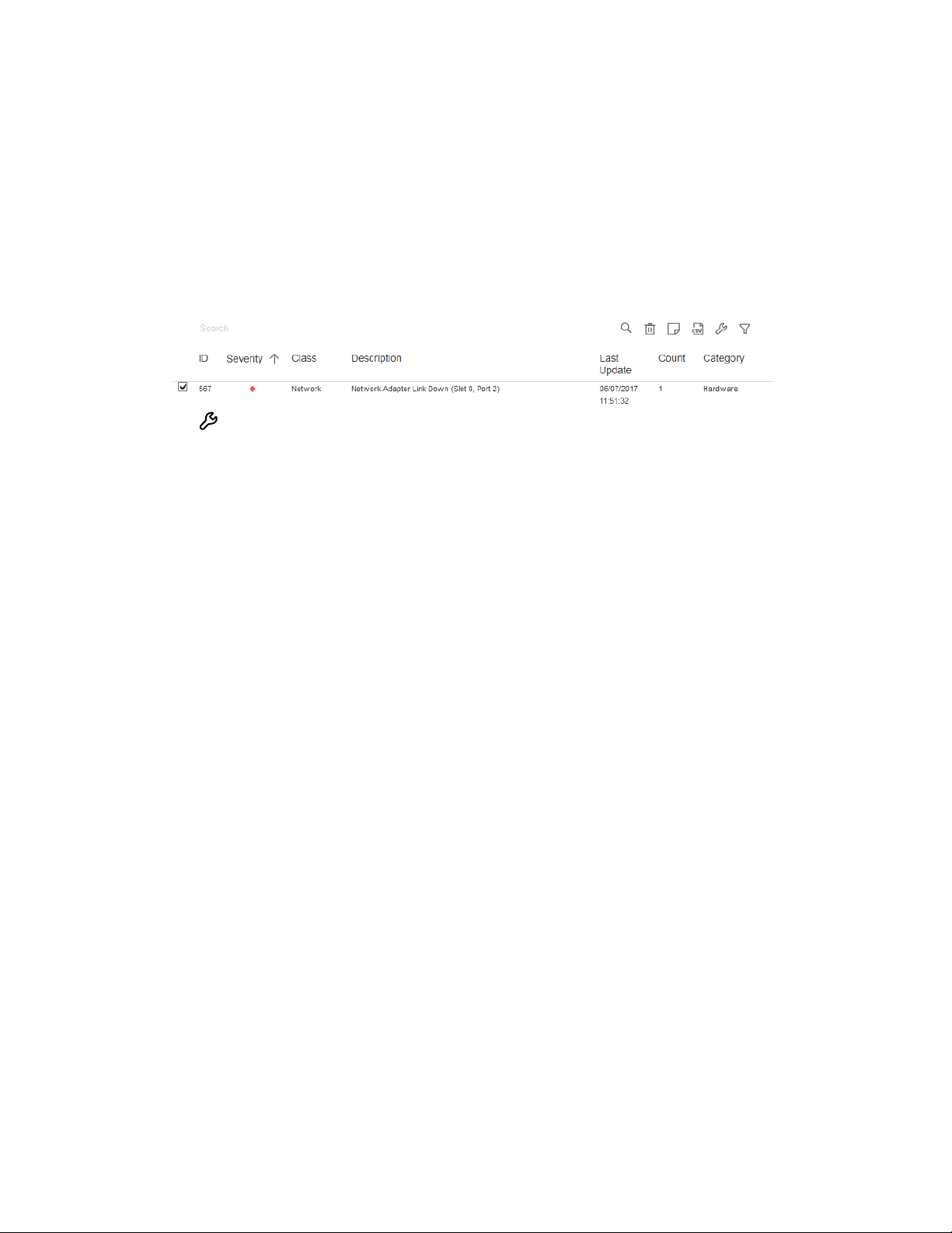
Procedure
Configure iLO Settings privilege
1. Investigate and repair the issue.
2. Click Information in the navigation tree, and then click the Integrated Management Log tab.
3. Select the log entry.
To select an IML entry, click the check box next to the entry in the first column of the IML
table. If a check box is not displayed next to an IML entry, that entry cannot be marked as
repaired.
4. Click .
The iLO web interface refreshes, and the selected log entry status changes to Repaired.
35
Page 42
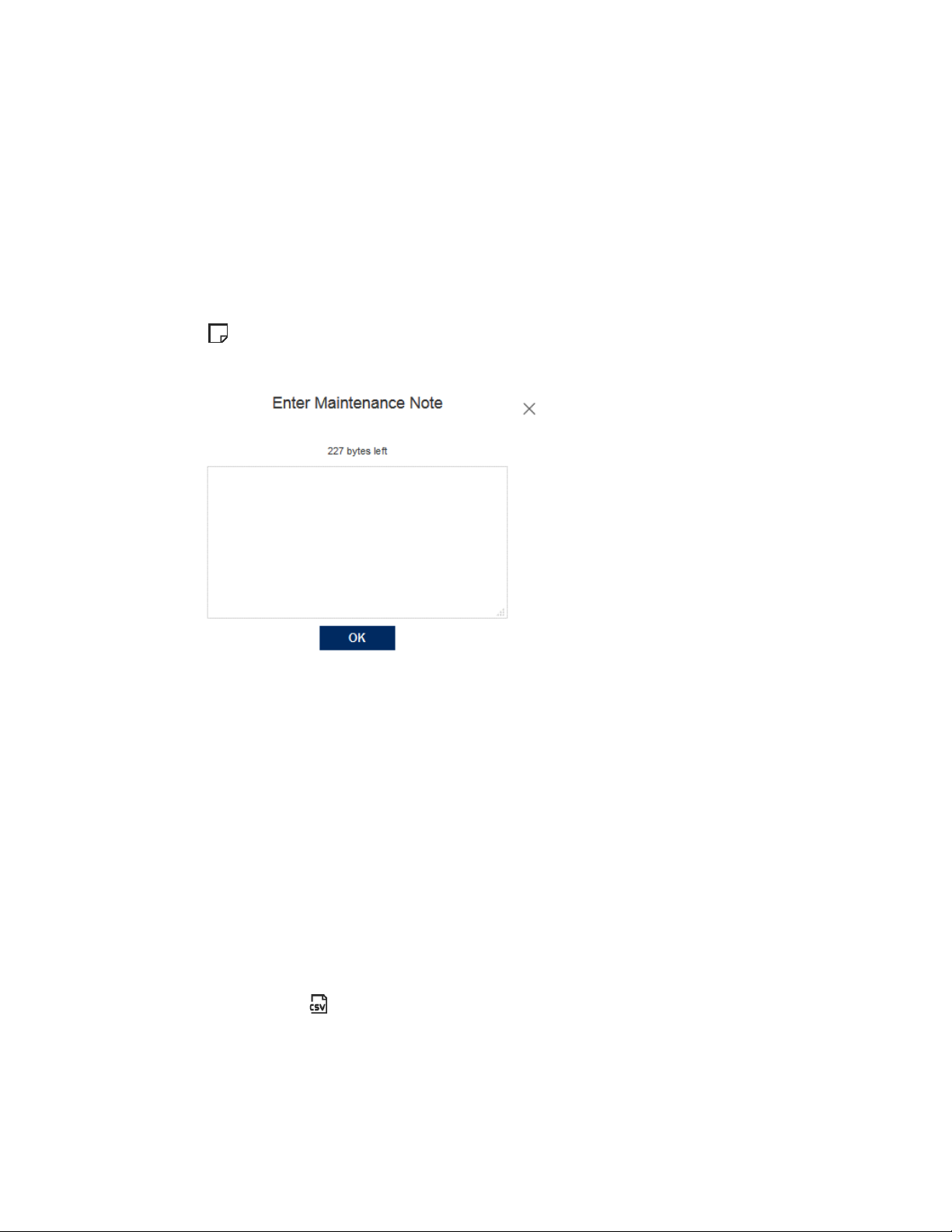
Adding a maintenance note to the IML
Use maintenance notes to create log entries about maintenance activities such as upgrades,
system backups, periodic system maintenance, or software installations.
Prerequisites
Configure iLO Settings privilege
Procedure
1. Click Information in the navigation tree, and then click the Integrated Management Log
tab.
2. Click .
The Enter Maintenance Note window opens.
3. Enter the text that you want to add as a log entry, and then click OK.
You can enter up to 227 bytes of text. You cannot submit a maintenance note without
entering some text.
An Informational log entry with the class Maintenance is added to the IML.
Saving the IML to a CSV file
Use a supported browser to export the IML to a CSV file.
Procedure
1. Click Information in the navigation tree, and then click the Integrated Management Log
tab.
2. Click the CSV icon .
3. In the CSV Output window, click Save, and then follow the browser prompts to save or open
the file.
36
Page 43
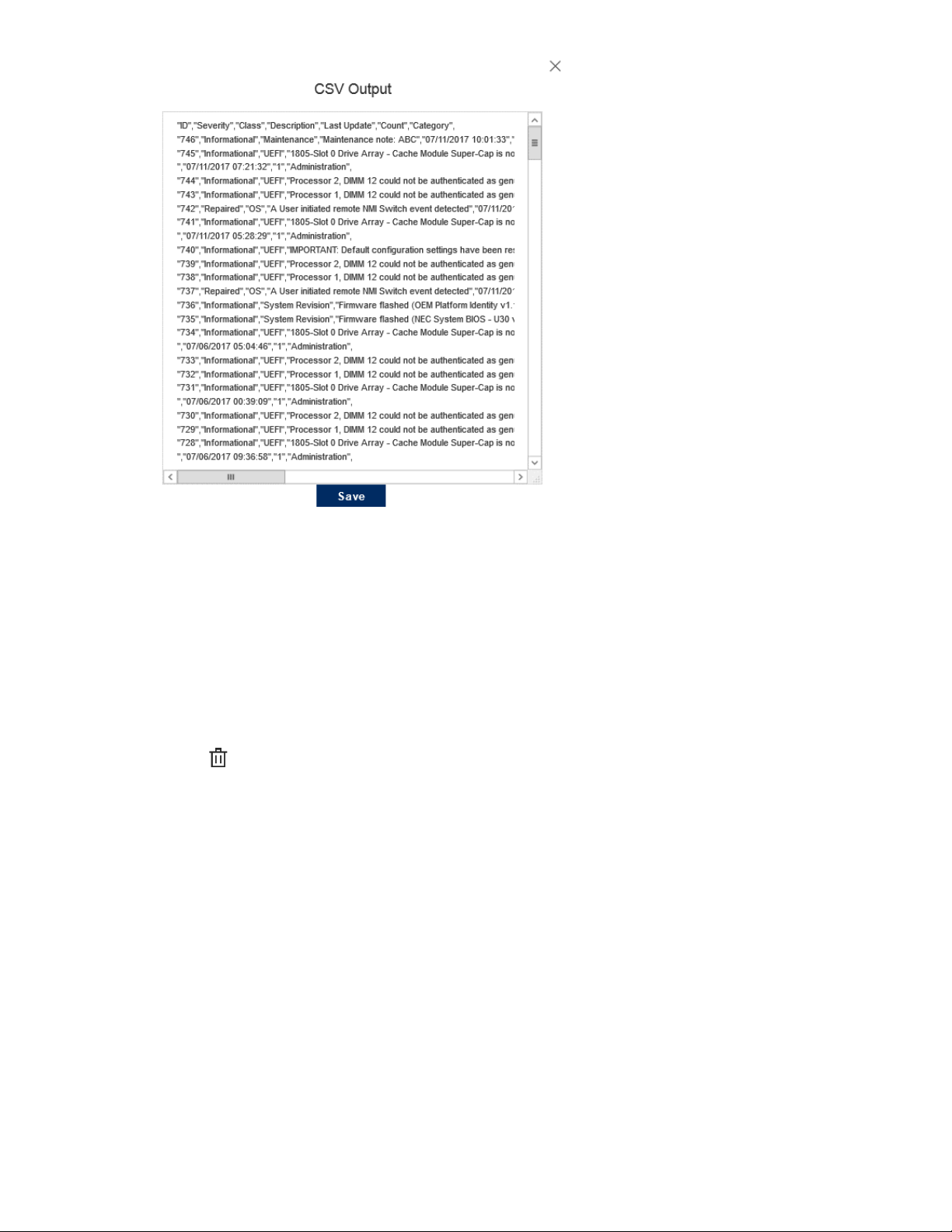
Clearing the IML
Prerequisites
Configure iLO Settings privilege
Procedure
1. Click Information in the navigation tree, and then click the Integrated Management Log
tab.
2. Click .
3. When prompted to confirm the request, click OK.
The IML is cleared of all previously logged information and an event is recorded in the IML.
37
Page 44

Active Health System
The Active Health System monitors and records changes in the server hardware and system
configuration.
The Active Health System provides:
• Continuous health monitoring of over 1600 system parameters
• Logging of all configuration changes
• Consolidated health and service alerts with precise time stamps
• Agentless monitoring that does not affect application performance
Active Health System data collection
The Active Health System does not collect information about your operations, finances,
customers, employees, or partners.
Examples of information that is collected:
• Server model and serial number
• Processor model and speed
• Storage capacity and speed
• Memory capacity and speed
• Firmware/BIOS and driver versions and settings
The Active Health System does not parse or change OS data from third-party error event log
activities (for example, content created or passed through the OS).
Active Health System Log
The data collected by the Active Health System is stored in the Active Health System Log. The
data is logged securely, isolated from the operating system, and separate from customer data.
When the Active Health System Log is full, new data overwrites the oldest data in the log.
When you download and send Active Health System data to NEC Corporation, you agree to have
the data used for analysis, technical resolution, and quality improvements.
Downloading the Active Health System Log for a date range
Procedure
1. Click Information in the navigation tree, and then click the Active Health System Log tab.
The Active Health System Log is inaccessible when it is being used by System Utilities,
EXPRESSBUILDER, or the iLO Service Port.
38
Page 45

2. Enter the range of days to include in the log. The default value is seven days.
a. Click the From box.
A calendar is displayed.
b. Select the range start date on the calendar.
c. Click the To box.
A calendar is displayed.
d. Select the range end date on the calendar.
To reset the range to the default values, click the Reset icon .
3. Optional: Enter the following information to include in the downloaded file:
• Support case number
• Contact name
• Phone number
• Email address
• Company name
This information is not written to the log data stored on the server.
4. Click Download.
5. Save the file.
Downloading the entire Active Health System Log
It might take a long time to download the entire Active Health System Log. If you must upload
the Active Health System Log for a technical issue, NEC Corporation recommends downloading
the log for the specific range of dates in which the problem occurred.
Procedure
1. Click Information in the navigation tree, and then click Active Health System Log.
The Active Health System Log is inaccessible when it is being used by System Utilities,
EXPRESSBUILDER, or the iLO Service Port.
2. Click Show Advanced Settings.
3. Optional: Enter the following information to include in the downloaded file:
• Support case number
• Contact name
• Phone number
• Email address
39
Page 46

• Company name
This information is not written to the log data stored on the server.
4. Click Download Entire Log.
5. Save the file.
Clearing the Active Health System Log
If the log file is corrupted, or if you want to clear and restart logging, use the following
procedure to clear the Active Health System Log.
Prerequisites
Configure iLO Settings privilege
Procedure
1. Click Information in the navigation tree, and then click the Active Health System Log tab.
The Active Health System Log is inaccessible when it is being used by EXPRESSBUILDER, the
Active Health System download CLI tool, or the iLO Service Port.
2. Click Show Advanced Settings.
3. Scroll to the Clear Log section, and then click Clear.
4. When prompted to confirm the request, click OK.
iLO notifies you that the log is being cleared.
5. Reset iLO.
Resetting iLO is required because some Active Health System data is recorded to the log
only during iLO startup. Performing this step ensures that a complete set of data is available
in the log.
6. Reboot the server.
Rebooting the server is required because some information, such as the operating system
name and version, is logged at server startup. Performing this step ensures that a complete
set of data is available in the log.
40
Page 47
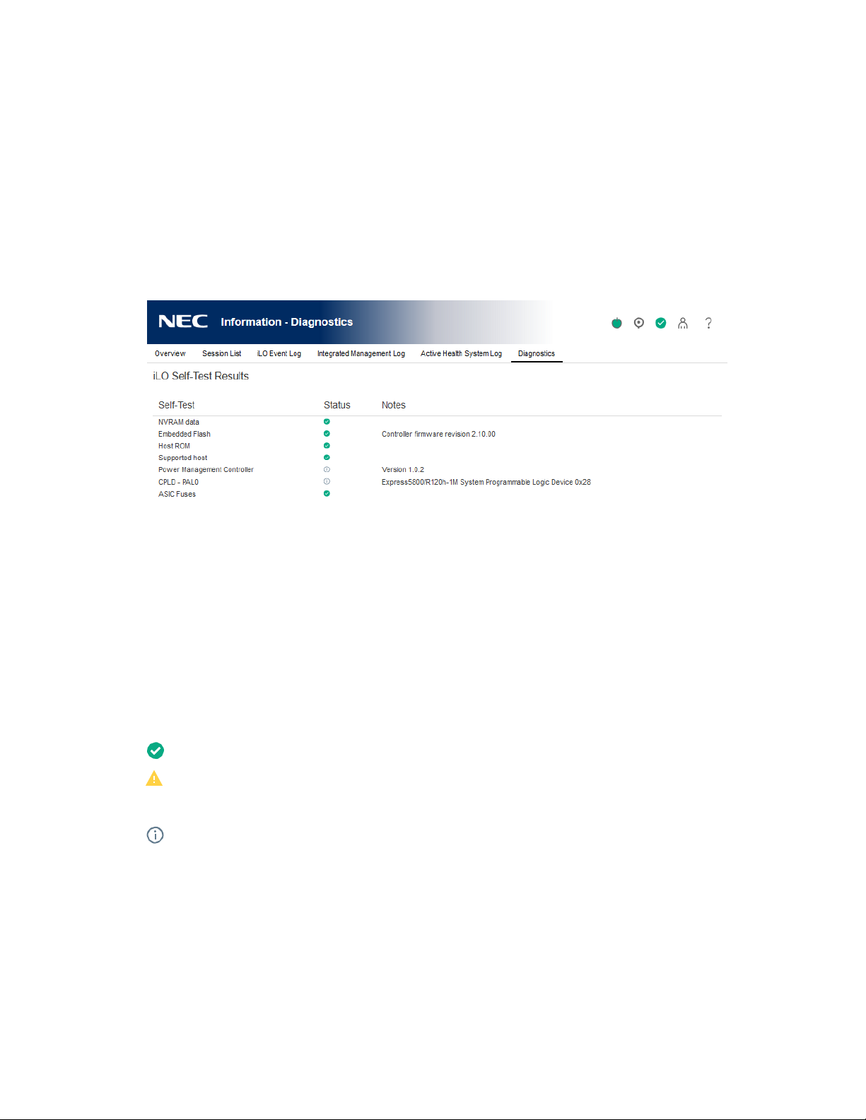
Viewing iLO self-test results
The iLO Self-Test Results section displays the results of internal iLO diagnostic tests, including
the test name, status, and notes.
The tests that are run are system-dependent. Not all tests are run on all systems. To see the tests
that are performed on your system, view the list on the Diagnostics page.
If a status is not reported for a test, the test is not listed.
Procedure
1. Click Information in the navigation tree, and then click the Diagnostics tab.
iLO self-tests
Self-test details
Self-Test
The tested function.
Status
The test status.
• Pass—The test was successful.
• Fail—The test detected a problem. A reboot, firmware or software update, or service
might be required.
• Informational—Supplemental data about the tested system is provided in the Notes column.
Notes
A test might include supplemental information in the Notes column.
For some tests, this column displays the versions of other system programmable logic, such as
the System Board PAL or the Power Management Controller.
iLO self-test types
The tests that are run are system-dependent. Not all tests are run on all systems. The possible
tests include:
41
Page 48

• Cryptographic—Tests security features.
• NVRAM—Tests the subsystem that retains nonvolatile configuration data, logs, and settings.
• Embedded Flash—Tests the state of the system that can store configuration, provisioning,
and service information.
• Power Management—Tests functions related to power measurement, power capping, and
power management.
• CPLD—Tests the programmable hardware in the server.
• Host ROM—Checks the BIOS to determine whether it is out-of-date compared to the
management processor.
• Supported Host—Checks the management processor firmware to determine whether it is
out of date for the server hardware.
• EEPROM— Tests the hardware that stores basic iLO properties that are assigned during the
manufacturing process.
42
Page 49
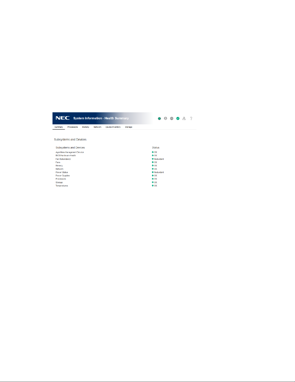
5. Viewing general system information
Viewing health summary information
The Health Summary page displays the status of monitored subsystems and devices. Depending
on the server configuration, the information on this page varies.
If the server is powered off, the system health information on this page is current as of the last
power off. Health information is updated only when the server is powered on and POST is
complete.
Procedure
1. Click System Information in the navigation tree.
Redundancy status
Redundancy status is displayed for the following:
• Fan Redundancy
• Power Status
Subsystem and device status
Summarized status information is displayed for the following:
• Agentless Management Service
• BIOS/Hardware Health
• Fans
• Memory
• Network
• Power Supplies
• Processors
• Storage
• Temperatures
• Smart Storage Battery Status (supported servers only)
43
Page 50

Subsystem and device status values
The Health Summary page uses the following status values:
• Redundant—There is a backup component for the device or subsystem.
• OK—The device or subsystem is working correctly.
• Not Redundant—There is no backup component for the device or subsystem.
• Not Available—The component is not available or not installed.
• Degraded—The device or subsystem is operating at a reduced capacity.
iLO displays the power supply status as Degraded when mismatched power supplies are
installed.
If you power on a server with nonredundant fans or power supplies, the system health status
is listed as OK. However, if a redundant fan or power supply fails while the system is
powered on, the system health status is listed as Degraded until you replace the fan or
power supply.
• Failed Redundant—The device or subsystem is in a nonoperational state.
• Failed—One or more components of the device or subsystem are nonoperational.]
• Other—For more information, navigate to the System Information page of the component
that is reporting this status.
• Link Down—The network link is down.
• Unknown—The iLO firmware has not received data about the device status. If iLO was reset
when the server was powered off, some subsystems display the status Unknown because
the status cannot be updated when the server is powered off.
• Not Installed—The subsystem or device is not installed.
44
Page 51
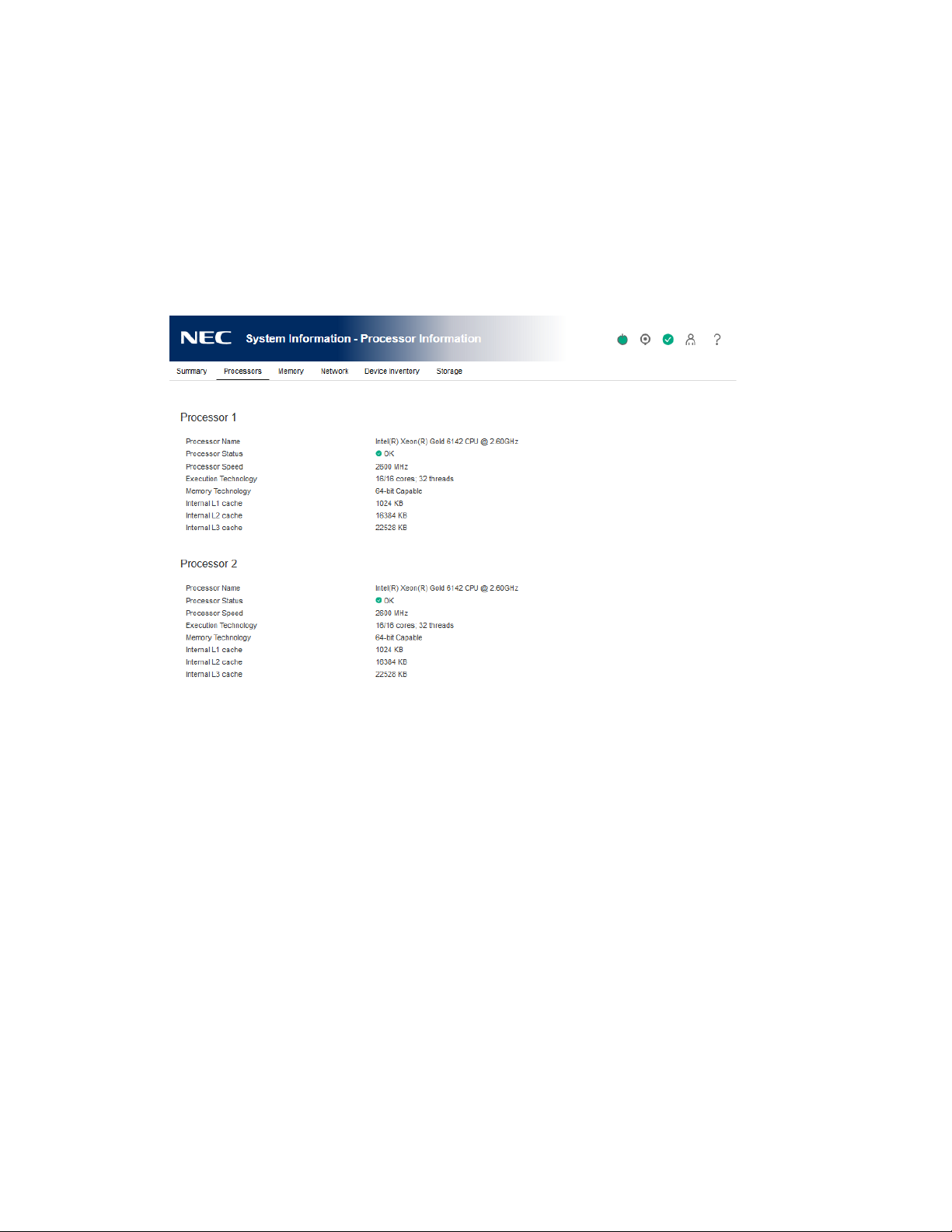
Viewing processor information
The Processor Information page displays the available processor slots, the type of processor
installed in each slot, and a summary of the processor subsystem.
If the server is powered off, the system health information on this page is current as of the last
power off. Health information is updated only when the server is powered on and POST is
complete.
Procedure
(ア) Click System Information in the navigation tree, and then click the Processors tab.
Processor details
The following information is displayed for each processor:
• Processor Name—The name of the processor.
• Processor Status—The health status of the processor.
• Processor Speed—The speed of the processor.
• Execution Technology—Information about the processor cores and threads.
• Memory Technology—The processor memory capabilities.
• Internal L1 cache—The L1 cache size.
• Internal L2 cache—The L2 cache size.
• Internal L3 cache—The L3 cache size.
45
Page 52
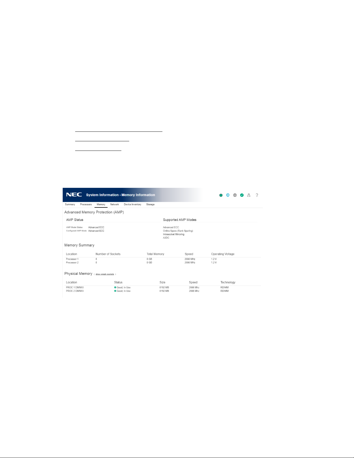
Viewing memory information
The Memory Information page displays a summary of the system memory. When server power is
off, AMP data is unavailable, and only memory modules present at POST are displayed.
If the server is powered off, the system health information on this page is current as of the last
power off. Health information is updated only when the server is powered on and POST is
complete.
Procedure
1. Click System Information in the navigation tree, and then click the Memory tab. The
Memory page displays details for the following:
• Advanced Memory Protection
• Memory Summary
• Memory Details
2. Optional: By default, empty memory sockets are hidden in the Memory Details table. To
view the empty memory sockets, click show empty sockets. When empty memory sockets
are displayed, click hide empty sockets to hide them.
Advanced Memory Protection details
AMP Mode Status
The status of the AMP subsystem.
• Other/Unknown—The system does not support AMP, or the management software cannot
determine the status.
• Not Protected—The system supports AMP, but the feature is disabled.
• Protected—The system supports AMP. The feature is enabled but not engaged.
• Degraded—The system was protected, but AMP is engaged. Therefore, AMP is no longer
available.
• DIMM ECC—The system is protected by DIMM ECC only.
• Mirroring—The system is protected by AMP in the mirrored mode. No DIMM faults have
been detected.
46
Page 53

• Degraded Mirroring—The system is protected by AMP in the mirrored mode. One or more
DIMM faults have been detected.
• On-line Spare—The system is protected by AMP in the hot spare mode. No DIMM faults
have been detected.
• Degraded On-line Spare—The system is protected by AMP in the hot spare mode. One or
more DIMM faults have been detected.
• RAID-XOR—The system is protected by AMP in the XOR memory mode. No DIMM faults
have been detected.
• Degraded RAID-XOR—The system is protected by AMP in the XOR memory mode. One or
more DIMM faults have been detected.
• Advanced ECC—The system is protected by AMP in the Advanced ECC mode.
• Degraded Advanced ECC—The system is protected by AMP in the Advanced ECC mode.
One or more DIMM faults have been detected.
• LockStep—The system is protected by AMP in the LockStep mode.
• Degraded LockStep—The system is protected by AMP in the LockStep mode. One or more
DIMM faults have been detected.
Configured AMP Mode
The active AMP mode. The following modes are supported:
• None/Unknown—The management software cannot determine the AMP fault tolerance, or
the system is not configured for AMP.
• On-line Spare—A single spare bank of memory is set aside at boot time. If enough ECC
errors occur, the spare memory is activated and the memory that is experiencing the errors
is disabled.
• Mirroring—The system is configured for mirrored memory protection. All memory banks
are duplicated in mirrored memory, as opposed to only one for online spare memory. If
enough ECC errors occur, the spare memory is activated and the memory that is
experiencing the errors is disabled.
• RAID-XOR—The system is configured for AMP with the XOR engine.
• Advanced ECC—The system is configured for AMP with the Advanced ECC engine.
• LockStep—The system is configured for AMP with the LockStep engine.
• Online Spare (Rank Sparing)—The system is configured for Online Spare Rank AMP.
• Online Spare (Channel Sparing)—The system is configured for Online Spare Channel AMP.
• Intersocket Mirroring—The system is configured for mirrored intersocket AMP between
the memory of two processors or boards.
• Intrasocket Mirroring—The system is configured for mirrored intrasocket AMP between the
memory of a single processor or board.
Supported AMP Modes
• RAID-XOR—The system can be configured for AMP using the XOR engine.
• Dual Board Mirroring—The system can be configured for mirrored advanced memory
protection in a dual memory board configuration. The mirrored memory can be swapped
with memory on the same memory board or with memory on the second memory board.
• Single Board Mirroring—The system can be configured for mirrored advanced memory
47
Page 54

protection in a single memory board.
• Advanced ECC—The system can be configured for Advanced ECC.
• Mirroring—The system can be configured for mirrored AMP.
• On-line Spare—The system can be configured for online spare AMP.
• LockStep—The system can be configured for LockStep AMP.
• Online Spare (Rank Sparing)—The system can be configured for Online Spare Rank AMP.
• Online Spare (Channel Sparing)—The system can be configured for Online Spare Channel
AMP.
• Intersocket Mirroring—The system can be configured for mirrored intersocket AMP
between the memory of two processors or boards.
• Intrasocket Mirroring—The system can be configured for mirrored intrasocket AMP
between the memory of a single processor or board.
• None—The system cannot be configured for AMP.
Memory Summary
The Memory Summary section shows a summary of the memory that was installed and
operational at POST.
Location
The slot or processor on which the memory board, cartridge, or riser is installed. Possible values
follow:
• System Board—There is no separate memory board slot. All DIMMs are installed on the
motherboard.
• Board <Number>—There is a memory board slot available. All DIMMs are installed on the
memory board.
• Processor <Number>—The processor on which the memory DIMMs are installed.
• Riser <Number>—The riser on which the memory DIMMs are installed.
Number of Sockets
The number of present memory module sockets.
Total Memory
The capacity of the memory, including memory recognized by the operating system and memory
used for spare, mirrored, or XOR configurations.
Operating Frequency
The frequency at which the memory operates.
Operating Voltage
The voltage at which the memory operates.
48
Page 55

Physical Memory Details
The Physical Memory Details section shows the physical memory modules on the host that were
installed and operational at POST. Unpopulated module positions are also listed. Various resilient
memory configurations can change the actual memory inventory from what was sampled at POST.
In systems that have a high number of memory modules, all module positions might not be listed.
Location
The slot or processor on which the memory module is installed.
Status
The memory module status and whether the module is in use.
Size
The size of the memory module, in MB.
Speed
The memory module speed.
Technology
The memory module technology. Possible values follow:
• Unknown—Memory technology cannot be determined.
• N/A—Not present.
• Synchronous
• RDIMM
• UDIMM
• LRDIMM
• NVDIMM
• NVDIMM-N
• R-NVDIMM
Logical Memory Details
This section shows the NEC Scalable Persistent Memory devices that were configured and
operational at POST.
Location
The processor and/or the region for the logical device. For example, PROC 1,2 Spanned Logical
NVDIMM, or PROC 1 Logical NVDIMM 1.
Status
The logical memory status.
Size
The size of the logical memory, in MB.
Speed
The logical memory speed.
Technology
The logical memory technology. Possible values follow:
• NVDIMM
• NVDIMM-N
• R-NVDIMM
49
Page 56
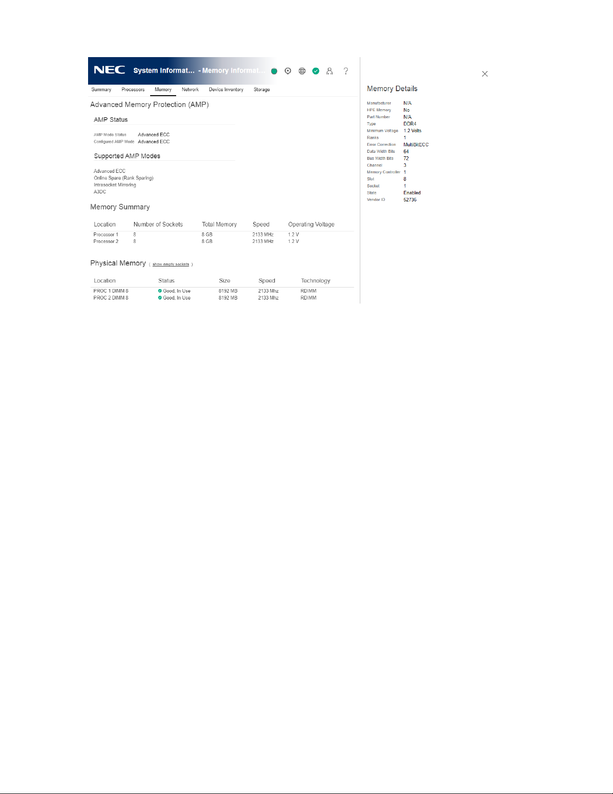
Memory Details pane
Physical Memory
Manufacturer
The memory module manufacturer.
Type
The type of memory installed. Possible values follow:
• Other—Memory type cannot be determined.
• Board—Memory module is permanently mounted (not modular) on a system board or
memory expansion board.
• DDR4
• N/A—Memory module is not present.
Minimum Voltage
The minimum voltage at which the memory module can operate.
Ranks
The number of ranks in the memory module.
Error Correction
The type of error correction used by the memory module.
Data Width Bits
The memory module data width in bits.
Bus Width Bits
The memory module bus width in bits.
Channel
The channel number in which the memory module is connected.
Memory Controller
The memory controller number.
Slot
The memory module slot number.
50
Page 57

Socket
The memory module socket number.
State
The memory state.
Vendor ID
The memory vendor ID.
Armed
The current backup-ready status of the NVDIMM-N, if available.
Last Operation
The status of the last operation.
Media Life
The percentage of media life left.
Logical Memory
Name
The memory module product name.
Manufacturer
The memory module manufacturer.
Power Backup Unit Bays
The number of battery backed unit bays that provide backup power to the logical DIMM.
Type
The type of memory installed.
The only possible value for logical memory is Logical.
Minimum Voltage
The minimum voltage at which the memory module can operate.
Ranks
The number of ranks in the memory module.
Error Correction
The type of error correction used by the memory module.
Data Width Bits
The memory module data width in bits.
Bus Width Bits
The memory module bus width in bits.
Memory Media
The proprietary media source of the memory module. For example, NAND or Proprietary.
State
The memory state.
Armed
The current backup-ready status of an NVDIMM-N, if available.
Last Operation
The status of the last operation.
Media Life
The percentage of media life left.
51
Page 58
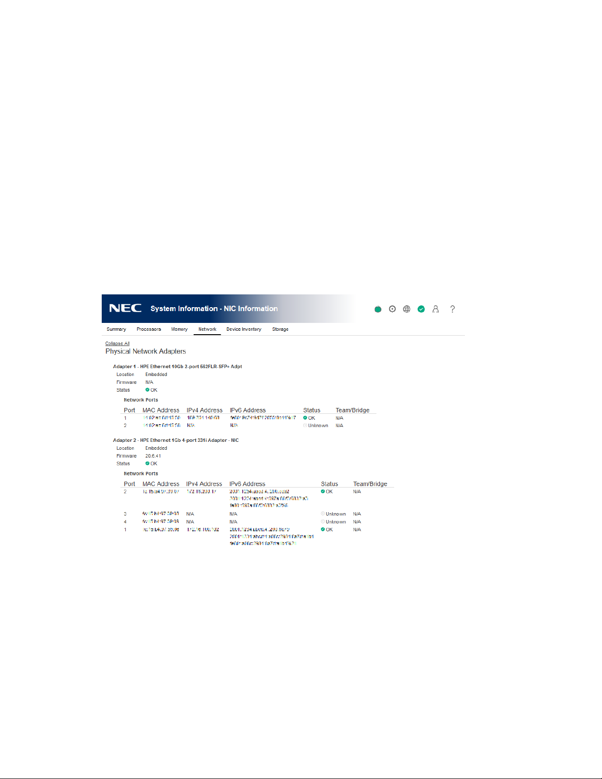
Viewing network information
If the server is powered off, the health status information on this page is current as of the last
power off. Health information is updated only when the server is powered on and POST is
complete.
To view a full set of data on this page, ensure that AMS is installed and running. The server IP
address, add in network adapters, and the server NIC status are displayed only if AMS is installed
and running on the server.
The information on this page is updated when you log in to iLO. To refresh the data, log out of
iLO, and then log back in.
Procedure
1. Click System Information in the navigation tree, and then click the Network tab.
2. Optional: To expand or collapse the information on this page, click Expand All or Collapse
All, respectively.
Physical Network Adapters
Integrated and add-in NICs and Fibre Channel adapters
This section displays the following information about the integrated and add-in NICs and Fibre
Channel adapters in the server:
• Adapter number—The adapter number, for example, Adapter 1 or Adapter 2.
• Location—The location of the adapter on the system board.
• Firmware—The version of the installed adapter firmware, if applicable. This value is
displayed for system NICs (embedded and stand-up) only.
• Status—The NIC status.
52
Page 59

◦ On Windows servers:
If the NIC has never been plugged in to a network, iLO displays the status Unknown.
If the NIC has been plugged in to a network, and is now unplugged, iLO displays the
status Link Down.
◦ On Linux servers:
If NetworkManager is used to manage the NIC, the default status is Up and the link
status is displayed in iLO.
If Linux legacy utilities are used to manage the NIC, iLO displays the link status only if
the NIC is configured by an administrator. If the NIC is not configured, iLO displays the
status Unknown.
◦ On VMware servers:
If iLO cannot communicate with the NIC port, it displays the status Unknown. If the NIC
driver reports the status link_down, iLO displays the status Down.
If the NIC driver reports the status link_up, iLO displays the status Up.
• Port—The configured network port. This value is displayed for system NICs (embedded and
stand-up) only.
• MAC Address—The port MAC address.
• IPv4 Address—For iLO adapters, the iLO IPv4 address. For system NICs (embedded and
stand-up), the server IP address (if available).
• IPv6 Address—For iLO adapters, the iLO IPv6 address. For system NICs (embedded and
stand-up), the server IP address (if available).
• Status—The port status.
• Team/Bridge—If a port is configured for NIC teaming, the name of the configured link
between the physical ports that form a logical network adapter. This value is displayed for
system NICs (embedded and stand-up) only.
Fibre Channel host bus adapters or converged network adapters
The following information is displayed for Fibre Channel host bus adapters or converged
network adapters:
• Physical Port—The physical network port number.
• WWNN—The port world-wide node name.
• WWPN—The world-wide port name.
• Status—The port status.
Boot progress and boot targets
The following information about the boot progress and boot targets is displayed when DCI
connectivity is available:
• Port—The configured virtual port number.
• Boot Progress—The current boot status.
• Boot Targets
◦ WWPN—The world-wide port name.
◦ LUN ID—The logical unit number ID.
53
Page 60

Logical Network Adapters
This section displays the following information about network adapters that use NIC teaming to
combine two or more ports into a single logical network connection:
Adapter name—The name of the configured link between the physical ports that form the
logical network adapter.
• MAC Address—The logical network adapter MAC address.
• IP Address—The logical network adapter IP address.
• Status—The logical network adapter status.
The following information is displayed for the ports that form each logical network adapter:
• Members—A sequential number assigned to each port that forms the logical network
adapter.
• MAC Address—The MAC address of the physical adapter port.
• Status—The status of the physical adapter port.
54
Page 61
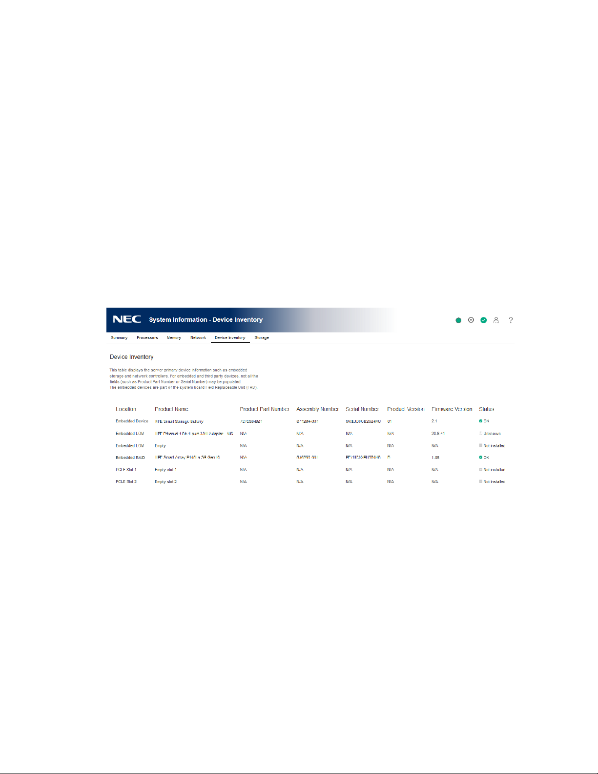
Viewing the device inventory
The Device Inventory page displays information about devices installed on the system board.
Some examples of the devices listed on this page include installed adapters, PCI devices, SATA
controllers, and Smart Storage batteries.
If the server is powered off, the health status information on this page is current as of the last
power on. Health information is updated only when the server is powered on and POST is
complete.
The following information is displayed only if AMS is installed and running on the server:
Firmware version and status of add-in network adapters, network-attached storage details, and
Smart Storage Battery status.
If the iLO firmware cannot retrieve the network adapter product name or part number directly
from the device, it attempts to collect that information from AMS.
Procedure
1. Click System Information in the navigation tree, and then click the Device Inventory tab.
Device Inventory details
• Location—The device install location.
• Product Name—The device product name.
• Product Part Number—The device part number.
This column displays the value Various when the actual part number of the listed device
depends on internally installed graphics devices that differ by server model.
• Assembly Number—The device part number (NEC Corporation devices) or the EEPROM
Board Info data (third-party devices).
• Serial Number—The device serial number.
• Product Version—The device product version.
• Firmware Version—The installed device firmware version.
• Status—The device status.
55
Page 62

Device status values
The Device Inventory page uses the following status values:
• OK—The device is working correctly.
• Other—The device status could not be determined.
• No Supporting CPU—The CPU that supports the device slot is not installed.
• Not Installed—A device is not installed.
• Link Down—The network link is down.
• Failed—One or more components of the device are nonoperational.
• Degraded—The device is operating at a reduced capacity.
• Unknown—The iLO firmware has not received data about the device status.
Viewing PCI slot details
Procedure
1. Click System Information in the navigation tree, and then click the Device Inventory tab.
2. Move the cursor over the Location column for a listed PCI slot.
PCI slot tooltip details
• Type—The PCI slot type.
• Bus Width—The PCI slot bus width.
• Length—The PCI slot length.
• Characteristics 1—Information about the PCI slot, for example, voltage and other support
information.
• Characteristics 2—Information about the PCI slot, for example, voltage and other support
information.
56
Page 63
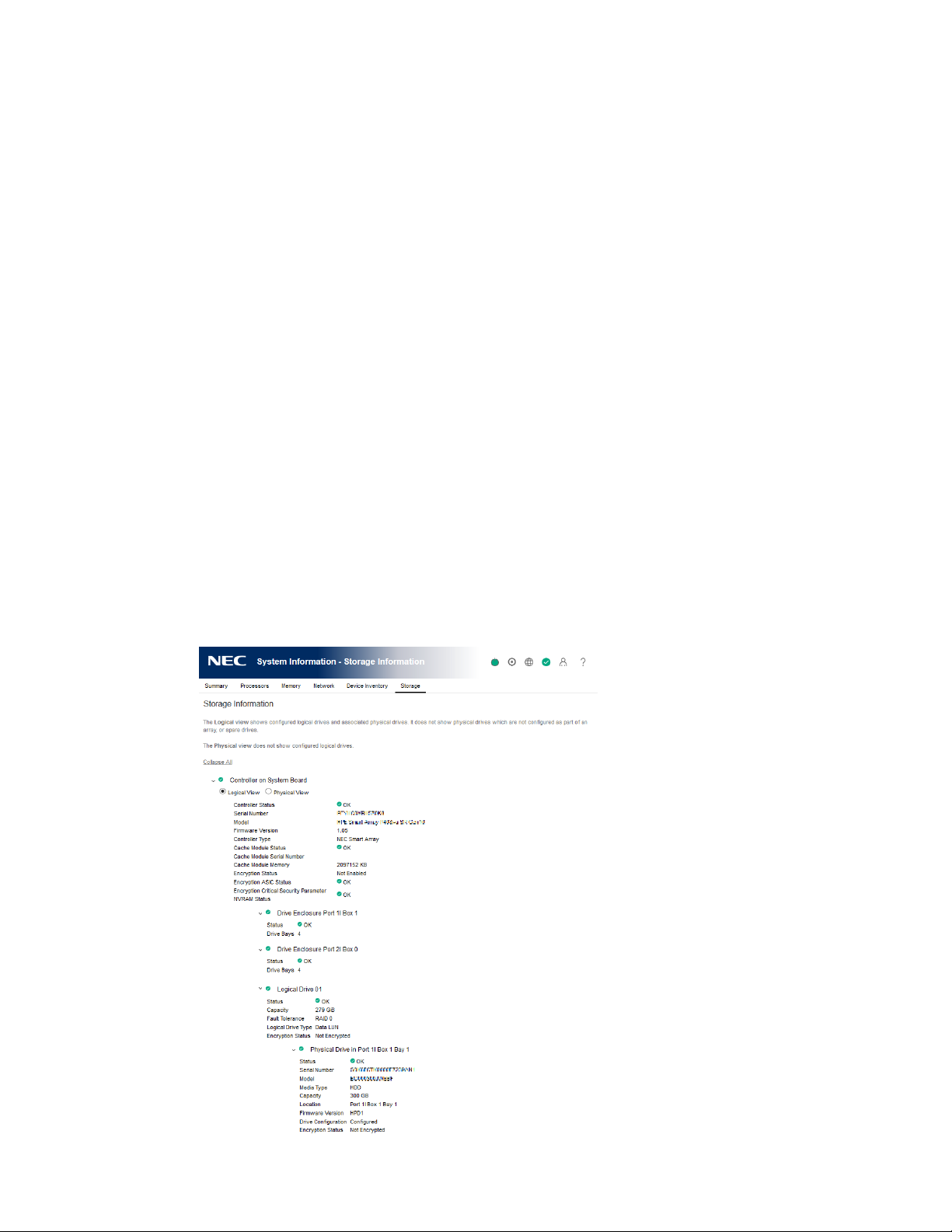
Viewing storage information
If the server is powered off, the system health information on this page is current as of the last
power off. Health information is updated only when the server is powered on and POST is
complete.
To view a full set of data on this page, ensure that AMS is installed and running. SAS/SATA
controller information is displayed only if AMS is installed and running on the server.
The information displayed on this page depends on your storage configuration. Some storage
configurations will not display information for every category.
Fibre Channel adapters are not listed on this page. To view information about Fibre Channel
adapters, click System Information in the navigation tree, and then click the Network tab.
Procedure
1. Click System Information in the navigation tree, and then click the Storage tab.
2. Optional: To expand or collapse the data, click Expand All or Collapse All, respectively.
3. Smart Array controllers only: For the controller you want to view, select one of the following
options:
• Logical View—View configured logical drives and associated physical drives. This view
does not show physical drives that are not configured as part of an array, or spare
drives.
• Physical View—View physical drives. This view does not show logical drives.
57
Page 64

Supported storage components
The Storage Information page displays information about the following storage components:
• Smart Array controllers, drive enclosures, the attached logical drives, and the physical drives
that constitute the logical drives.
• NEC and third-party storage controllers that manage direct-attached storage, and the
attached physical drives.
iLO 5 supports the following products:
◦ M.2 SSD Enablement Kit
◦ 12G SAS Expander
◦ Dual 8GB MicroSD EM USB Kit
◦ NVMe drives
Smart Array controllers are listed first on the page, followed by other NEC Corporation and
third-party storage controllers.
Smart Array details
iLO displays information controllers, enclosures, logical drives, and physical drives.
iLO can monitor 256 physical drives total and 256 logical drives total.
Controllers
This section provides the following details for each Smart Array controller.
• Controller location—Slot number or system board
• Top-level controller status (displayed on the left of the controller location)—A combination
• Controller Status—Controller hardware status (OK or Failed)
• Serial Number
• Model
• Firmware Version
• Controller Type
• Cache Module Status
• Cache Module Serial Number
• Cache Module Memory
• Encryption Status—Indicates whether encryption is enabled in the controller.
of the controller hardware status and the status of cache modules, enclosures, and physical,
logical, and spare drives associated with the controller. If the controller hardware status is
OK, and any associated hardware has a failure, the top-level controller status changes to
Major Warning or Degraded, depending on the failure type. If the controller hardware has
a Failed status, the top-level controller status is Failed.
The following values are possible:
◦ Enabled
◦ Not Enabled
◦ Enabled—Local Mode—This value is displayed when you do not use a remote key
58
Page 65

• Encryption ASIC Status—Indicates whether the ASIC encryption self tests for the controller
passed or failed. A failed status indicates that the controller is not encrypted.
• Encryption Critical Security Parameter NVRAM Status—Indicates whether the controller
successfully detected the critical security parameter NVRAM. A failed status means that the
controller is not encrypted.
The encryption settings for a Smart Array controller can be configured by using the Smart
Storage Administrator software.
Drive enclosures
This section provides the following information about the drive enclosures attached to a Smart
Array controller.
• Enclosure port and box numbers
• Status
• Drive Bays—The number of drive bays
• Serial Number
• Model
• Firmware Version
management server.
Some enclosures do not have all the listed properties, and some storage configurations do not
have drive enclosures.
Logical drives
When the Logical View option is selected, the following information is listed for the logical
drives attached to a Smart Array controller.
• Logical drive number
• Status
• Capacity
• Fault Tolerance
• Logical Drive Type
• Encryption Status
Logical drives must be configured through the Smart Storage Administrator software before they
can be displayed on this page.
Physical drives
The information listed in this section depends on whether the Logical View or Physical View
option is selected. In the Logical View, physical drives that are configured as part of an array are
listed. In the Physical View, all physical drives are listed.
When a physical drive has a Failed status, this status does not affect the overall storage health
status. Only logical drives affect the storage health status.
The following information is listed for the physical drives attached to a Smart Array controller:
• Physical drive port, box, and bay numbers
59
Page 66

• Status
• Serial Number
• Model
• Media Type
• Capacity
• Location
• Firmware Version
• Drive Configuration
• Encryption Status
Direct-attached storage details
Controllers
This section provides the following information about the NEC Corporation and third-party
storage controllers that manage direct-attached storage.
• Controller location
• Top-level controller status—The top-level controller status (displayed on the left of the
controller location) is a combination of the controller hardware status and the status of the
enclosures, physical drives, and spare drives associated with the controller. If the controller
hardware status is OK, and any associated hardware has a failure, the top-level controller
status changes to Major Warning or Degraded, depending on the failure type. If the
controller hardware has a Failed status, the top-level controller status is Failed.
• Controller Status—Controller hardware status (OK or Failed)
• Serial Number
• Model
• Firmware Version
• Controller Type
Physical Drives
This section provides information about physical drives attached to NEC Corporation and thirdparty storage controllers.
When a physical drive has a Failed status, this status does not affect the overall storage health
status. Only logical drives affect the storage health status.
• Physical drive location
• Status
• Serial Number
• Model
• Media Type
• Capacity
• Location
• Firmware Version
• Drive Configuration
• Encryption Status
60
Page 67

61
Page 68

6. Managing firmware, software, and language packs
Firmware updates
Firmware updates enhance server and iLO functionality with new features, improvements, and
security updates.
You can update firmware by using an online or offline firmware update method.
Online firmware update
When you use an online method to update firmware, you can perform the update without
shutting down the server operating system. Online firmware updates can be performed in-band
or out-of-band.
In-band
Firmware is sent to iLO from the server host operating system.
The iLO 5 Channel Interface Driver is required for in-band firmware updates.
During a host-based firmware update, it does not verify user credentials or privileges because
the host-based utilities require a root (Linux and VMware) or Administrator (Windows) login.
The iLO Online ROM Flash Component is examples of online in-band firmware update
methods.
Out-of-band
Firmware is sent to iLO over a network connection. Users with the Configure iLO Settings
privilege can update firmware by using an out-of-band method. If the system maintenance
switch is set to disable iLO security, any user can update firmware with an out-of-band
method.
The iLO web interface, the iLO RESTful API, and SMASH CLP are examples of online out-ofband firmware update methods.
Online firmware update methods
In-band firmware updates
• Online ROM Flash Component—Use an executable file to update firmware while the
server is running. The executable file contains the installer and the firmware package.
You can download online ROM flash components for iLO and server firmware at the
following website: http://www.nec.com/express/.
This option is supported when iLO is configured to use the Production security state.
Out-of-band firmware updates
62
Page 69

• iLO web interface—Download a supported firmware file and install it by using the iLO
web interface. You can update firmware for a single server or an iLO Federation group.
• iLO RESTful API—Use the iLO RESTful API and a REST client such as the RESTful Interface
Tool to update firmware.
• SMASH CLP—Access SMASH CLP through the SSH port, and use standard commands to
view firmware information and update firmware.
Offline firmware update
When you use an offline method to update the firmware, you must reboot the server by using an
offline utility.
The SPP, SUM are examples of offline firmware update methods.
Offline firmware update methods
You can use the following offline firmware update methods:
Starter Pack
Use the StarterPack to install firmware.
SUM
SUM is a tool for firmware, driver, and software maintenance on supported servers and other
nodes.
You can use SUM together with iLO to access the iLO repository and manage install sets and
the installation queue.
Viewing and updating firmware from the iLO web interface
The iLO web interface supports the following firmware and software management features:
• Viewing installed firmware.
• Viewing installed software.
• Using the Flash Firmware controls to install firmware on the local managed server.
• Using the Group Firmware Update feature to install firmware on multiple servers in an iLO
Federation group.
• Accessing the iLO with integrated Smart Update features. This version of iLO supports the
following actions:
◦ Manage the iLO Repository and add saved components to the installation queue.
◦ View and remove install sets and add them to the installation queue.
◦ Use SUM to configure install sets.
The best practice is to use SUM to manage the installation queue. You can use the iLO
web interface to update the queue by adding or removing an individual component.
You can access the iLO Repository and the Flash Firmware controls from all tabs on the
Firmware & OS Software page.
63
Page 70
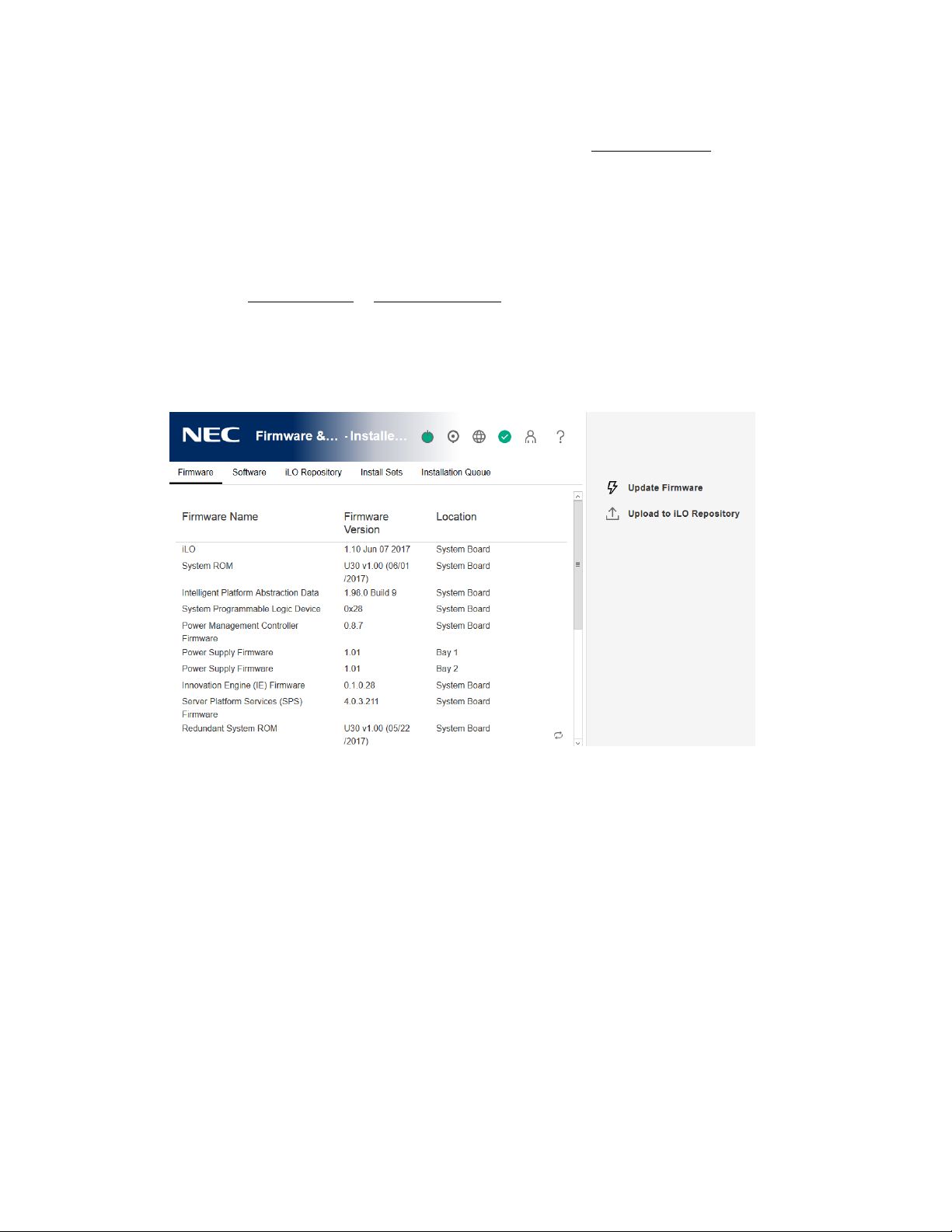
Updating iLO or server firmware by using the Flash Firmware feature
You can update firmware from any network client by using the iLO web interface. A signed file is
required. You can also initiate a component update from the iLO Repository page.
Prerequisites
Configure iLO Settings privilege
Procedure
1. Obtain an iLO firmware or server firmware file.
2. Click Firmware & OS Software in the navigation tree, and then click Update Firmware.
If the Update Firmware option is not displayed, click the ellipsis icon in the top right corner
of the iLO web interface, then click Update Firmware.
3. Select the Local file or Remote file option.
4. Depending on the option you selected, do one of the following:
• In the Local binary file box, click Browse (Internet Explorer or Firefox) or Choose Files
(Chrome), and then specify the location of the firmware component.
• In the Remote binary file URL box, enter the URL for a firmware component on an
accessible web server.
5. Optional: To save a copy of the component to the iLO Repository, select the Also store in
iLO Repository check box.
6. To start the update process, click Flash.
Depending on the server configuration, iLO notifies you that:
• When you update the iLO firmware, iLO will reboot automatically.
Some types of server firmware might require a server reboot, but the server will not
reboot automatically.
• A TPM or TM is installed in this server. Before you initiate a system ROM or iLO firmware
64
Page 71

update, suspend or back up any software that stores information on the TPM or TM. For
example, if you use drive encryption software, suspend it before initiating a firmware
update. Failure to follow these instructions might result in losing access to your data.
7. Do one of the following:
• If a TPM or TM message was not displayed, click OK.
• If a TPM or TM message was displayed, verify that any software that stores data on the
TPM or TM is suspended or backed up, and then click OK.
The iLO firmware receives, validates, and then flashes the firmware image.
When you update the iLO firmware, iLO reboots and closes your browser connection. It
might take several minutes before you can re-establish a connection.
8. For iLO firmware updates only: To start working with the new firmware, clear your browser
cache, and then log in to iLO.
9. For server firmware updates only: If the firmware type requires a system reset or server
reboot for the new firmware to take effect, take the appropriate action. For more
information, see Requirements for firmware update to take effect .
10. Optional: To confirm that the new firmware is active, check the firmware version on the
Installed Firmware page.
You can also check the iLO firmware version on the Overview page.
Supported firmware types
Many types of firmware update are supported, depending on the server platform. These types
include:
• iLO
• System ROM/BIOS
• Chassis
• Power Management Controller
• Programmable Logic (CPLD)
• Backplane
• Language Packs
Requirements for firmware update to take effect
• iLO firmware or language pack—Requires an iLO reset, which is triggered automatically.
• System ROM (BIOS)—Requires a server reboot.
• Chassis firmware (Power Management)—Take effect immediately.
• System Programmable Logic Device (CPLD)—Requires a server reboot.
• Power Management Controller and NVMe Backplane Firmware—Do not require a server
reboot or a system reset.
The NVMe firmware version will be displayed in the iLO web interface after the next server
reboot.
65
Page 72

Obtaining the iLO firmware image file
You can download an iLO firmware image file and use it to update a single server or multiple
servers in an iLO Federation group.
The BIN file from the iLO Online ROM Flash Component is required for updating the iLO
firmware with the
Flash Firmware and Group Firmware Update features.
Procedure
1. Navigate to the following website: http://www.nec.com/express/.
2. To locate and download the iLO Online ROM Flash Component file, follow the onscreen
instructions.
Download a Windows or Linux component.
3. Extract the BIN file.
• For Windows components: Double-click the downloaded file, and then click the Extract
button. Select a location for the extracted files, and then click OK.
• For Linux components: Depending on the file format, enter one of the following
commands:
◦ #sh ./CP00XXXX.scexe –unpack=/tmp/
◦ #rpm2cpio <firmware_file_name>.rpm | cpio -id
The name of the iLO firmware image file is similar to iLO 5_<yyy>.bin, where <yyy>
represents the firmware version.
66
Page 73
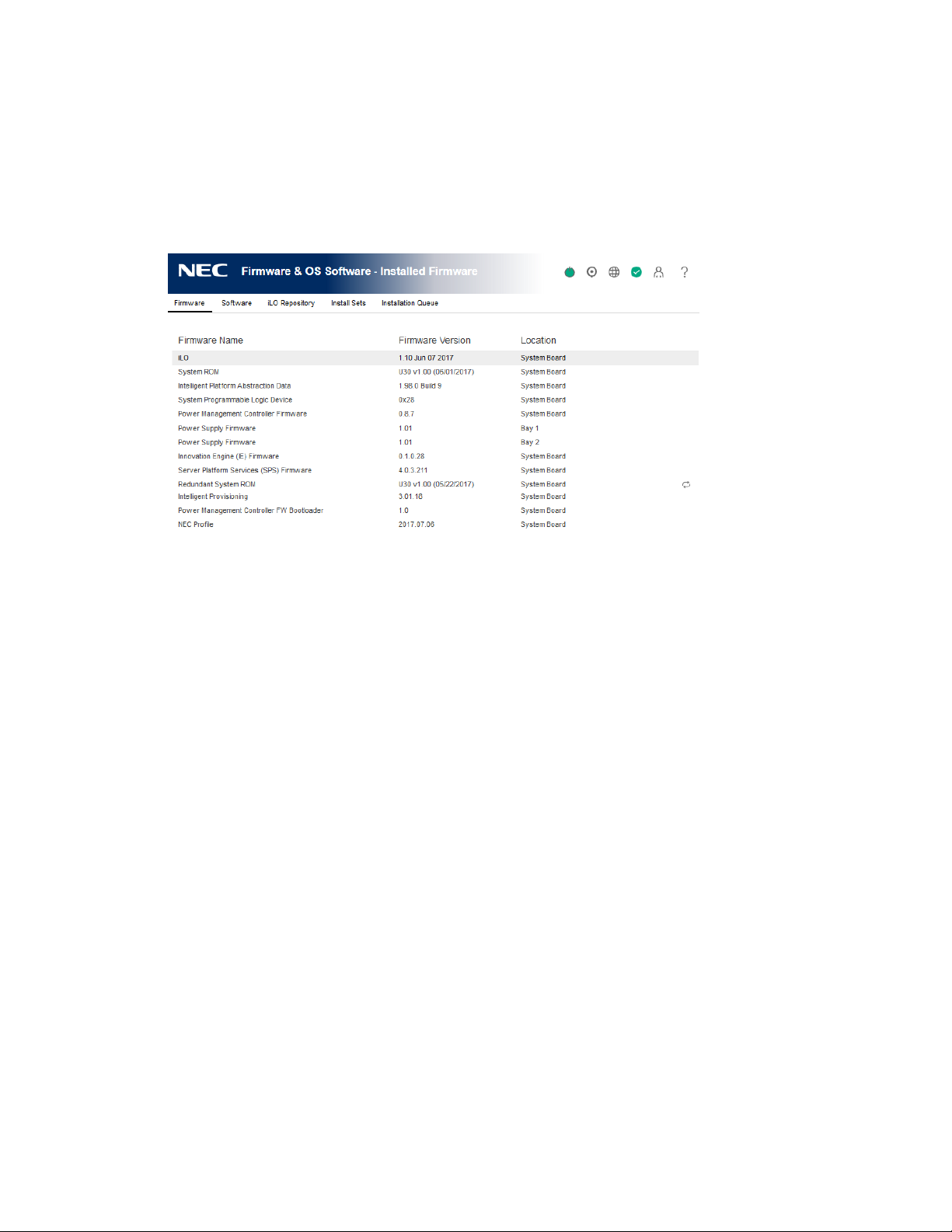
Viewing installed firmware information
Procedure
1. Click Firmware & OS Software in the navigation tree.
The Installed Firmware page displays firmware information for various server components.
If the server is powered off, the information on this page is current as of the last power off.
Firmware information is updated only when the server is powered on and POST is complete.
Firmware types
The firmware types listed on the Installed Firmware page vary based on the server model and
configuration.
For most servers, the system ROM and iLO firmware are listed. Other possible firmware options
include the following:
• Power Management Controller
• Server Platform Services Firmware
• Smart Array
• Intelligent Platform Abstraction Data
• Smart Storage Battery
• TPM or TM firmware
• SAS Programmable Logic Device
• System Programmable Logic Device
• EXPRESSBUILDER
• Networking adapters
• NVMe Backplane firmware
• Innovation Engine (IE) firmware
• Drive firmware
• Power Supply firmware
67
Page 74

Firmware details
The Installed Firmware page displays the following information for each listed firmware type:
• Firmware Name—The name of the firmware.
• Firmware Version—The version of the firmware.
• Location—The location of the component that uses the listed firmware.
Replacing the active system ROM with the redundant system ROM
Prerequisites
• The server supports redundant system ROM.
• Virtual Power and Reset privilege
Procedure
1. Click Firmware & OS Software in the navigation tree.
2. On the Firmware tab, click the swap icon next to the Redundant System ROM details.
iLO prompts you to confirm the request.
3. Click OK.
The change will take effect after the next server reboot.
68
Page 75
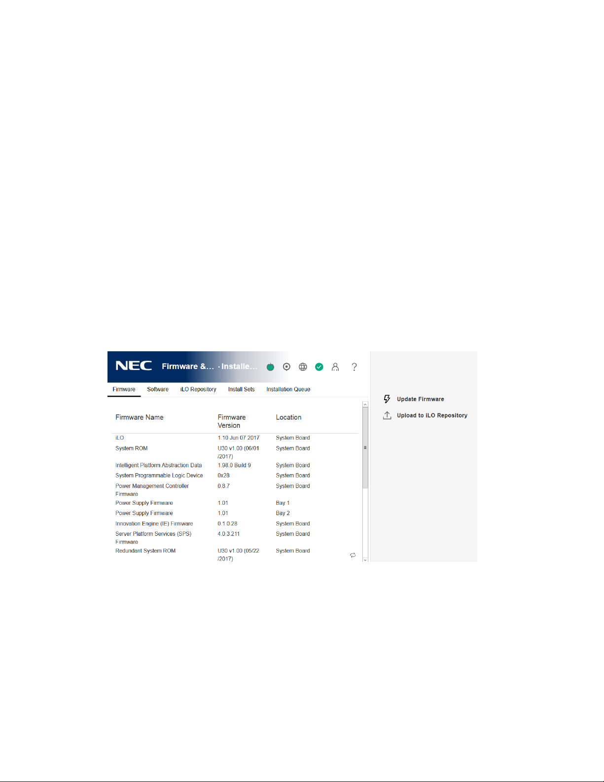
iLO Repository
The iLO Repository is a secure storage area in the nonvolatile flash memory embedded on the
system board. This flash memory is called the iLO NAND. Use SUM or iLO to manage signed
software and firmware components in the iLO Repository.
iLO, the UEFI BIOS, SUM, and other client software can retrieve these components and apply
them to supported servers. Use SUM to organize the stored components into install sets and
SUM or iLO to manage the installation queue.
Adding a component to the iLO Repository
Prerequisites
Configure iLO Settings privilege
Procedure
1. Click Firmware & OS Software in the navigation tree, and then click Upload to iLO
Repository.
If the Upload to iLO Repository option is not displayed, click the ellipsis icon in the top
right corner of the iLO web interface, then click Upload to iLO Repository.
2. Select the Local file or Remote file option.
3. Depending on the option you selected, do one of the following:
• In the Local binary file box, click Browse (Internet Explorer or Firefox) or Choose Files
(Chrome), and then specify the location of the firmware component.
• In the Remote binary file URL box, enter the URL for a firmware component on an
accessible web server.
4. For firmware components specified by multiple files only: Select the I have a component
signature file check box.
5. If you selected the check box in the previous step, do one of the following:
69
Page 76

• In the Local component signature file box, click Browse (Internet Explorer or Firefox)
or Choose Files (Chrome), and then specify the location of the component signature
file.
• In the Remote component signature file URL box, enter the URL for a component
signature file on an accessible web server.
6. Click Upload.
iLO notifies you that uploading a component with the same name as an existing component
will replace the existing component. Components that are part of the Recovery Set are
protected and cannot be replaced by uploading a new component with the same name. To
replace a Recovery Set component, log in with an account that has the Recovery Set
privilege, and then delete the recovery install set.
7. Click OK.
The upload starts. The upload status is displayed at the top of the iLO web interface.
Installing a component from the iLO Repository
You can add a component to the installation queue from the iLO Repository page.
When you add a component to the installation queue, it is added to the end of the queue. After
other queued items are complete, the added component is installed when the software that
initiates updates for the component type detects the installation request. To determine the
software that can initiate an update, check the component details on the iLO Repository and
Installation Queue pages.
If a component in a previously queued task is waiting to start or finish, a new queued
component might be delayed indefinitely. For example, if a queued update must wait until the
UEFI BIOS detects it during server POST, but the server is not restarted, then the updates that
follow in the queue will not be installed.
Prerequisites
Configure iLO Settings privilege
Procedure
1. Click Firmware & OS Software in the navigation tree, and then click iLO Repository.
70
Page 77
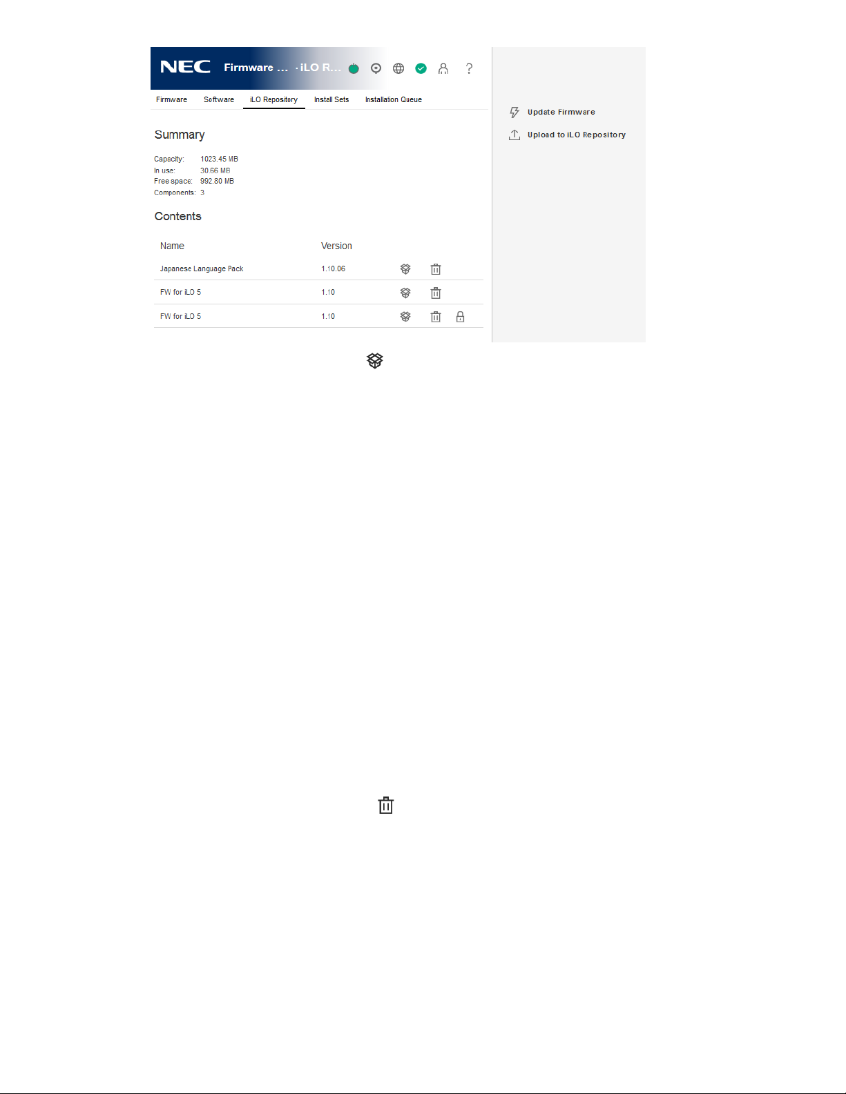
2. Click the install component icon next to the component you want to install.
iLO notifies you that the component will be added to the end of the installation queue, and
prompts you to confirm the request.
3. Click Yes, add to the end of the queue.
If the installation queue is empty, and iLO can initiate the component installation, the button
is labeled Yes, install now.
The update is initiated after existing queued tasks finish and the software that initiates
installation for the selected component type detects a pending installation. If the installation
queue is empty and iLO can initiate the update, the update begins immediately.
Removing a component from the iLO Repository
Prerequisites
• Configure iLO Settings privilege
• The component is not in an install set.
• The component is not part of a queued task.
Procedure
1. Click Firmware & OS Software in the navigation tree, and then click the iLO Repository tab.
2. Click the remove component icon . iLO prompts you to confirm the request.
3. Click Yes, remove.
The component is removed.
Viewing iLO Repository summary and component details
Procedure
1. Click Firmware & OS Software in the navigation tree, and then click the iLO Repository tab.
2. Optional: To view detailed component information, click an individual component.
71
Page 78
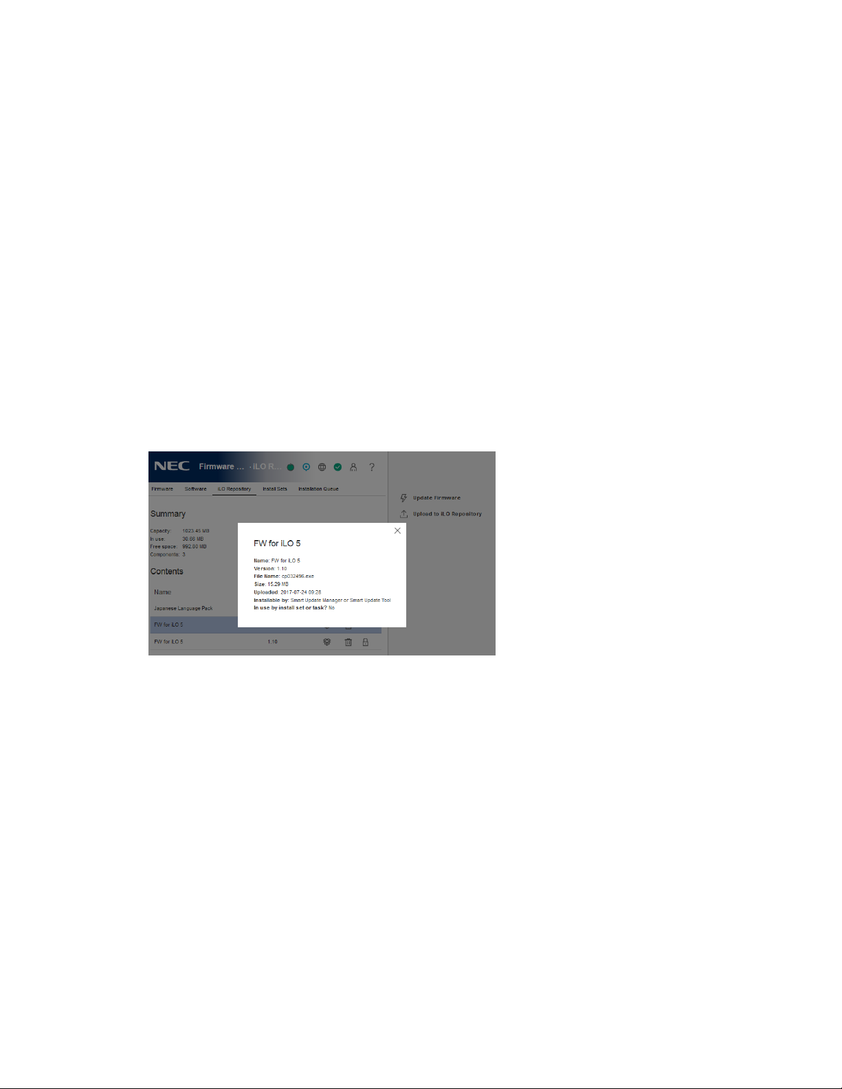
iLO Repository details
iLO Repository storage details
The Summary section of the iLO Repository page displays the following details about the iLO
Repository storage use:
• Capacity—Total iLO Repository storage capacity
• In Use—Used storage
• Free Space—Available iLO Repository storage
• Components—Number of saved components in the iLO Repository
iLO Repository contents
The Contents section of the iLO Repository page displays the following details about each
firmware or software component:
• Name
• Version
iLO Repository individual component details
When you click an individual component, the following details are displayed:
• Name—Component name
• Version—Component version
• File Name—Component file name
• Size—Component size
• Uploaded—Upload date and time
• Installable by—The software that can initiate an update with the component.
• In use by install set or task?—Whether the component is part of an install set.
72
Page 79

Install Sets
An install set is a group of components that can be applied to supported servers with a single
command. Use SUM to create install sets. You can use iLO to view existing install sets in the iLO
web interface.
Saving an install set when you deploy from SUM keeps all the components on the iLO system for
immediate use at a later time to restore or roll back a component version without needing to
find the original SPP.
Installing an install set
You can add an install set to the installation queue from the Install Sets page.
When you add an install set to the installation queue, iLO adds a task to the end of the
installation queue for each component or command in the install set. After other queued items
are complete, the install set contents are installed when the software that initiates updates for
each component type detects the installation request. To determine the software that can
initiate an update, check the component details.
If a component in a previously queued task is waiting to start or finish, a new queued
component might be delayed indefinitely. For example, if a queued update must wait until the
UEFI BIOS detects it during server POST, but the server is not restarted, then the updates that
follow in the queue will not be installed.
Prerequisites
• Configure iLO Settings privilege
• No components in the install set are queued as part of another installation task.
Procedure
1. Click Firmware & OS Software in the navigation tree, and then click Install Sets.
2. Click the install icon next to the install set you want to install.
iLO notifies you that the contents of the install set will be added to the end of the installation
queue, and prompts you to confirm the request.
3. Click Yes, add to the end of the queue..
If the installation queue is empty, and iLO can initiate the updates in the install set, the button is
labeled Yes, install now.
The updates are initiated after existing queued tasks finish and the software that initiates
installation for the selected component types detects a pending installation.
If the installation queue is empty and iLO can initiate the requested updates, the update begins
immediately.
73
Page 80

Removing an Install Set
Prerequisites
• Configure iLO Settings privilege for unprotected install sets.
• Recovery Set privilege for removing the protected install set.
Procedure
1. Click Firmware & OS Software in the navigation tree, and then click Install Sets.
2. Click the remove install set icon .
iLO prompts you to confirm the request.
3. Click Yes, remove.
The install set is removed.
Viewing Install Sets
Procedure
1. Click Firmware & OS Software in the navigation tree, and then click the Install Sets tab.
2. Optional: Click an install set to view detailed information.
Install Set details
Install Set summary details
The Install Sets tab displays the following details about each install set:
• Name—The install set name.
• Components/Commands—The components and commands in the install set.
Use the install set icons to add an install set to the installation queue or to remove an install
set. The protected install set is displayed with a lock icon.
Individual install set details
When you click an individual install set, the following details are displayed:
• Name—The install set name.
• Created—The creation date and time.
• Description—A description of the install set.
• Component/Commands—The components and commands in the install set.
System Recovery Set?—Indicates whether the install set can be edited or deleted. This status
is used for the system recovery set. Only one system recovery set can exist at a time.
74
Page 81

System recovery set
By default, a system recovery install set is included with every server. User accounts with the
Recovery Set privilege can configure this install set.
The following firmware components are included in the default system recovery set:
• System ROM (BIOS)
• iLO firmware
• System Programmable Logic Device (CPLD)
• Innovation Engine
• Server Platform Services (SPS) Firmware
If the default system recovery set is deleted, a user with the Recovery Set privilege can use SUM
to create an install set, and then designate it as the system recovery set by using the iLO RESTful
API. For instructions, see the SUM user guide. Only one system recovery install set can exist at a
time.
75
Page 82

Installation Queue
The installation queue is an ordered list of components that were added to the queue
individually or as parts of an install set. Use SUM to manage the queue. You can view queued
tasks and add single components to the queue from the iLO web interface.
When you add a component to the installation queue, it is added to the end of the queue. After
other queued items are complete, the added component is installed when the software that
initiates updates for the component type detects the installation request. To determine the
software that can initiate an update, check the component details on the iLO Repository and
Installation Queue pages.
If a component in a previously queued task is waiting to start or finish, a new queued
component might be delayed indefinitely. For example, if a queued update must wait until the
UEFI BIOS detects it during server POST, but the server is not restarted, then the updates that
follow in the queue will not be installed.
To learn more about how iLO, SUM, and the BIOS software work together to manage software
and firmware, see the SUM documentation.
Viewing the Installation Queue
Procedure
1. Click Firmware & OS Software in the navigation tree, and then click the Installation Queue
tab.
2. Optional: To view detailed information, click an individual task.
Queued task details
Task summary details
The Installation Queue tab displays the following details about each task:
State
Status of the task. The possible values follow:
• In progress—The task is being processed.
• Expired—The task is expired. Subsequent tasks will not run until this task is removed from
the queue.
• Exception—The task could not complete. Subsequent tasks will not run until this task is
removed from the queue.
• Complete—The task completed successfully.
• Pending—The task will run when the software that initiates updates for the component
type detects the installation request.
76
Page 83

Name
The task name.
Starts
The task start date and time.
Expires
The task expiration date and time.
Individual task details
When you click an individual task, the following details are displayed:
• Name—The task name.
• State—Task status.
• Result—Task results, if available.
• Installable by—The software that can initiate an update with the selected component.
• Start time—The task start date and time.
• Expiration—The task expiration date and time.
Removing a task from the Installation Queue
Prerequisites
Configure iLO Settings privilege
Procedure
1. Click Firmware & OS Software in the navigation tree, and then click Installation Queue.
2. Click the remove component icon .
iLO prompts you to confirm the request.
3. Click Yes, remove.
The component is removed.
77
Page 84
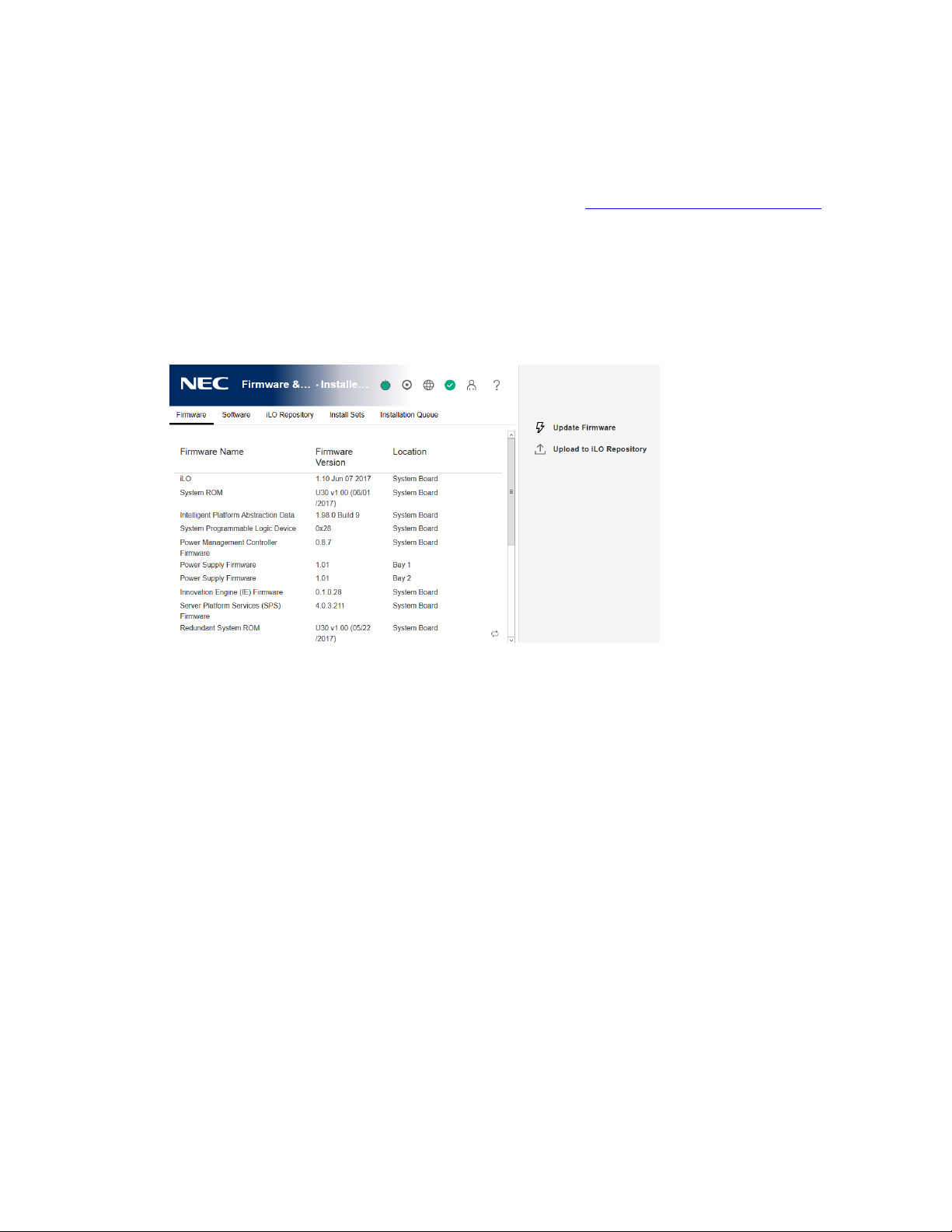
Installing language packs
Prerequisites
Configure iLO Settings privilege
Procedure
1. Download a language pack from the following website: http://www.nec.com/express/.
2. To extract the contents, double-click the downloaded file.
The language pack file name is similar to the following: lang_<language>_<version>.lpk.
3. Click Firmware & OS Software in the navigation tree, and then click Update Firmware.
The Flash Firmware controls appear.
4. Click Browse (Internet Explorer or Firefox) or Choose Files (Chrome).
5. Select a language pack, and then click Open.
6. Optional: To save a copy of the language pack file to the iLO Repository, select the Also
store in iLO Repository check box.
7. Click Flash.
iLO prompts you to confirm the installation request.
8. Click OK.
iLO installs the selected language pack, reboots, and closes your browser connection. It
might take several minutes before you can re-establish a connection.
78
Page 85
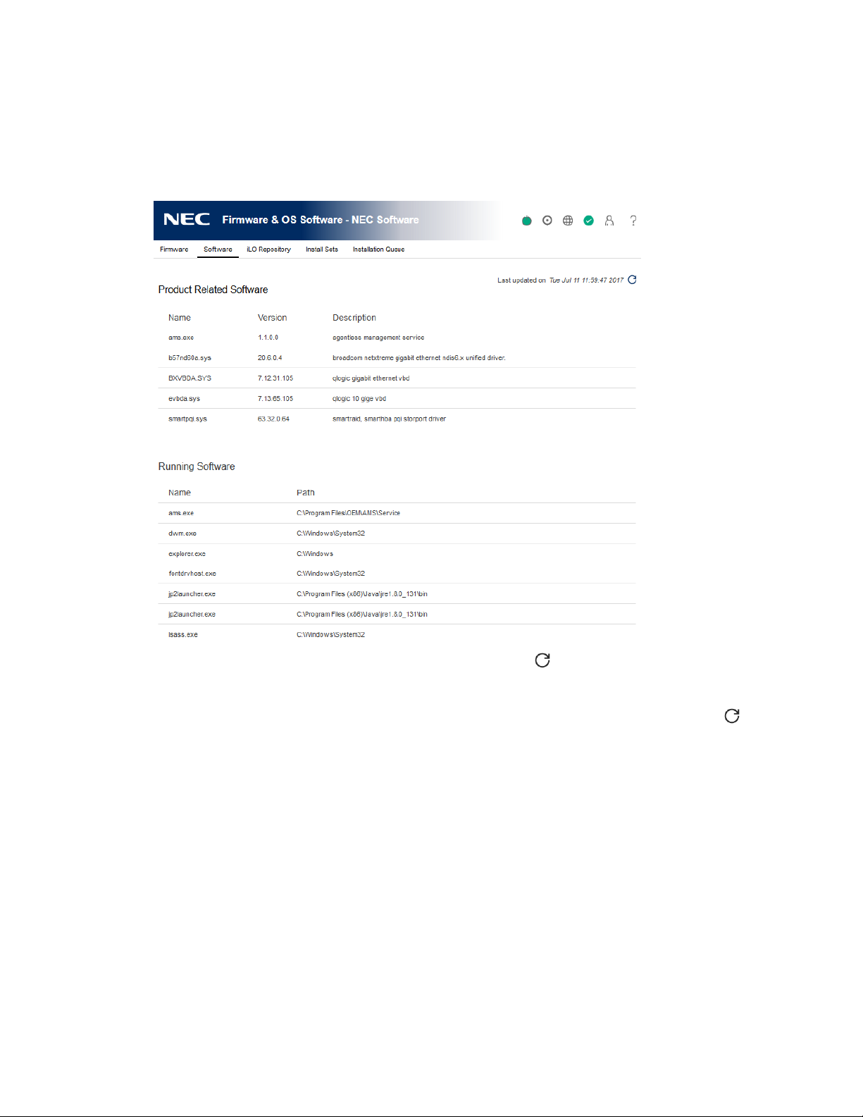
Viewing software information
Prerequisites
To display a complete set of data on this page, AMS must be installed.
Procedure
1. Click Firmware & OS Software in the navigation tree, and then click the Software tab.
2. Optional: To update the software information data, click .
The information on this page is cached in the browser, and iLO displays the date and time of
the last update. If 5 minutes or more have passed since the page was updated, click to
update the page with the latest information.
Product-related Software details
This section lists all the product-related software on the managed server. The list includes NEC
Corporation and NEC-recommended third-party software that was added manually or by using
the SPP.
• Name—The name of the software.
• Version—The software version.
The versions of the displayed firmware components indicate the firmware versions available in
the firmware flash components that are saved on the local operating system. The displayed
version might not match the firmware running on the server.
• Description—A description of the software.
79
Page 86

Running Software details
This section lists all the software that is running or available to run on the managed server.
• Name—The name of the software.
• Path—The file path of the software.
Installed Software details
The Installed Software list displays the name of each installed software program.
80
Page 87

7. Configuring and using iLO Federation
iLO Federation
iLO Federation enables you to manage multiple servers from one system using the iLO web
interface.
When configured for iLO Federation, iLO uses multicast discovery and peer-to-peer
communication to enable communication between the systems in an iLO Federation group.
When an iLO Federation page loads, a data request is sent from the iLO system running the web
interface to its peers, and from those peers to other peers until all data for the selected iLO
Federation group is retrieved.
iLO supports the following features:
• Group health status—View server health and model information.
• Group Virtual Media—Connect scripted media for access by the servers in an iLO Federation
group.
• Group power control—Manage the power status of the servers in an iLO Federation group.
• Group power capping—Set dynamic power caps for the servers in an iLO Federation group.
• Group firmware update—Update the firmware of the servers in an iLO Federation group.
• Group license installation—Enter a license key to activate iLO licensed features on the
servers in an iLO Federation group.
• Group configuration—Add iLO Federation group memberships for multiple iLO systems.
Any user can view information on iLO Federation pages, but a license is required for using the
following features: Group Virtual Media, Group power control, Group power capping, Group
configuration, and Group firmware update.
Configuring iLO Federation
Prerequisites for using the iLO Federation features
Procedure
• The network configuration meets the iLO Federation requirements.
• The multicast options are configured for each iLO system that will be added to an iLO
Federation group.
If you use the default multicast option values, configuration is not required.
• iLO Federation group memberships are configured.
All iLO systems are automatically added to the DEFAULT group.
81
Page 88

iLO Federation network requirements
• Servers that will be used with iLO Federation must use the iLO Dedicated Network Port
configuration. The iLO Federation features cannot be used with the iLO Shared Network Port
configuration.
• Optional: iLO Federation supports both IPv4 and IPv6. If both options have valid
configurations, you can configure iLO to use IPv4 instead of IPv6. To configure this setting,
clear the iLO Client Applications use IPv6 first check box on the iLO Dedicated Network Port
- IPv6 Settings page.
• Configure the network to forward multicast traffic if you want to manage iLO systems in
multiple locations.
• Ensure that multicast traffic is enabled if the switches in your network include the option to
enable or disable it. This configuration is required for iLO Federation and other NEC
Corporation products to discover the iLO systems on the network.
• For iLO systems that are separated by Layer 3 switches, configure the switches to forward
SSDP multicast traffic between networks.
• Configure the network to allow multicast traffic (UDP port 1900) and direct HTTP (TCP
default port 80) communication between iLO systems.
• For networks with multiple VLANs, configure the switches to allow multicast traffic between
the VLANs.
• For networks with Layer 3 switches:
◦ For IPv4 networks: Enable PIM on the switch and configure it for PIM Dense Mode.
◦ For IPv6 networks: Configure the switch for MLD snooping.
Configuring the multicast options for one iLO system at a time
Use the following procedure to configure the multicast options for each iLO system that will be
added to an iLO Federation group. If you use the default values, configuration is not required.
You can use the iLO RESTful API to view and configure multicast options for multiple iLO
systems.
Prerequisites
Configure iLO Settings privilege
Procedure
1. Click iLO Federation in the navigation tree. The Setup tab is displayed.
82
Page 89
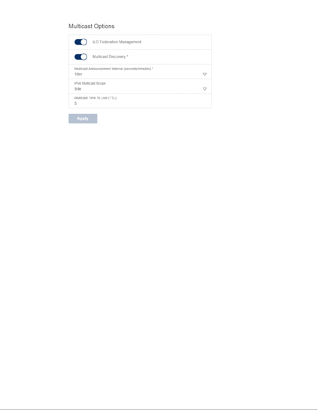
2. For iLO Federation Management, select Enabled or Disabled.
3. For Multicast Discovery, select Enabled or Disabled.
4. Enter a value for Multicast Announcement Interval (seconds/minutes).
5. Select a value for IPv6 Multicast Scope.
To ensure that multicast discovery works correctly, make sure that all iLO systems in the
same group use the same value for IPv6 Multicast Scope.
6. Enter a value for Multicast Time To Live (TTL).
To ensure that multicast discovery works correctly, make sure that all iLO systems in the
same group use the same value for Multicast Time to Live (TTL).
7. Click Apply.
Network changes and changes you make on this page take effect after the next multicast
announcement.
Multicast options
• iLO Federation Management—Enables or disables the iLO Federation features. The default
setting is Enabled. Selecting Disabled disables the iLO Federation features for the local iLO
system.
• Multicast discovery—Enables or disables multicast discovery. The default setting is
Enabled. Selecting Disabled disables the iLO Federation features for the local iLO system.
• Multicast Announcement Interval (seconds/minutes)—Sets the frequency at which the
iLO system announces itself on the network. Each multicast announcement is approximately
300 bytes. Select a value of 30 seconds to 30 minutes. The default value is 10 minutes.
Selecting Disabled disables the iLO Federation features for the local iLO system.
• IPv6 Multicast Scope—The size of the network that will send and receive multicast traffic.
Valid values are Link, Site, and Organization. The default value is Site.
• Multicast Time To Live (TTL)—Specifies the number of switches that can be traversed
before multicast discovery stops. The default value is 5.
83
Page 90

iLO Federation groups
iLO Federation group memberships for local iLO systems
When you configure group memberships for a local iLO system, you specify the privileges that
members of a group have for configuring the local managed server.
For example, if you add the local iLO system to group1 and assign the Virtual Power and Reset
privilege, the users of other iLO systems in group1 can change the power state of the managed
server.
If the local iLO system does not grant the Virtual Power and Reset privilege to group1, the users
of other iLO systems in group1 cannot use the group power control features to change the
power state of the managed server.
If the system maintenance switch is set to disable iLO security on the local iLO system, the users
of other iLO systems in group1 can change the state of the managed server, regardless of the
assigned group privileges.
Group memberships for the local iLO system are configured on the iLO Federation page Setup
tab. You can perform the following tasks for a local iLO system:
• View group memberships.
• Add and edit group memberships.
• Remove group memberships.
iLO Federation group memberships for a set of iLO systems
When you add group memberships for multiple iLO systems at one time, you specify the
privileges that members of the group have for configuring the other members of the group.
For example, if you configure group2 based on the DEFAULT group, and you assign the Virtual
Power and Reset privilege, the users of iLO systems in group2 can change the power state of all
the servers in the group.
You can add group memberships for multiple iLO systems on the Group Configuration page.
You can perform the following tasks for a group of iLO systems:
• Create a group with the same members as an existing group, but with different privileges.
• Create a group with members that you select by using the iLO Federation filters.
iLO Federation group privileges
When an iLO system added to a group, the group can be granted the following privileges:
• Login— Group members can log in to iLO.
• Remote Console—Group members can remotely access the managed server Remote
Console, including video, keyboard, and mouse control.
• Virtual Power and Reset—Group members can power-cycle or reset the host system.
84
Page 91

These activities interrupt the system availability.
• Virtual Media—Group members can use scripted Virtual Media with the managed server.
• Host BIOS—Group members can configure the host BIOS settings by using the UEFI System
Utilities.
• Configure iLO Settings—Group members can configure most iLO settings, including
security settings, and can remotely update firmware.
• Administer User Accounts—Group members can add, edit, and delete iLO user accounts.
• Host NIC—Group members can configure the host NIC settings.
• Host Storage—Group members can configure the host storage settings.
• Recovery Set—Group members can manage the recovery install set.
This privilege is not available if you start a session when the system maintenance switch is set to
disable iLO security.
iLO Federation group characteristics
• All iLO systems are automatically added to the DEFAULT group, which is granted the Login
privilege for each group member. You can edit or delete the DEFAULT group membership.
• iLO Federation groups can overlap, span racks and data centers, and can be used to create
management domains.
• An iLO system can be a member of up to 10 iLO Federation groups.
• There is no limit on the number of iLO systems that can be in a group.
• You must have the Configure iLO Settings privilege to configure group memberships.
• You can use the iLO web interface to configure group memberships for a local iLO system or
a group of iLO systems.
• You can use the iLO RESTful API to configure group memberships.
• NEC Corporation recommends installing the same version of the iLO firmware on iLO
systems that are in the same iLO Federation group.
85
Page 92
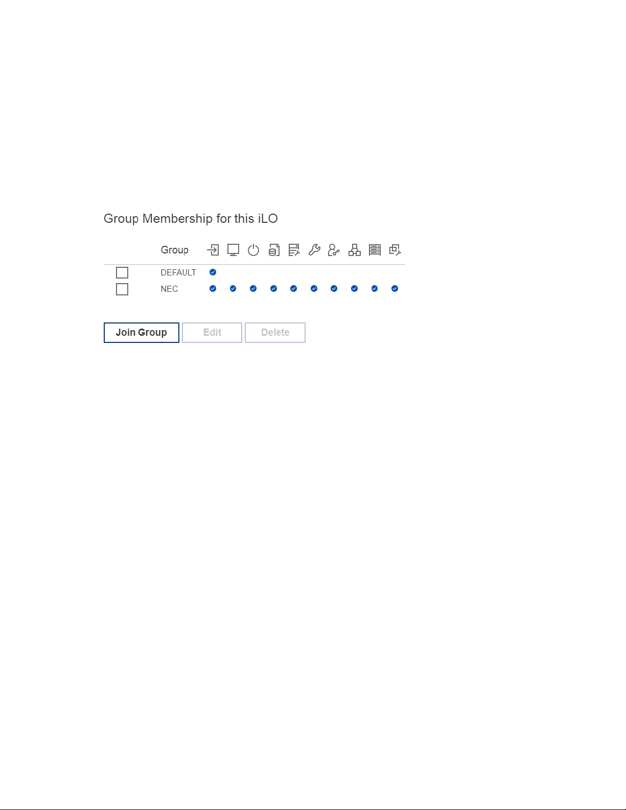
Managing iLO Federation group memberships (local iLO system)
Viewing iLO Federation group memberships (local iLO system)
Procedure
1. Click iLO Federation in the navigation tree.
The Group Membership for this iLO table lists the name of each group that includes the
local iLO system, and the privileges granted to the group by the local iLO system.
Adding iLO Federation group memberships
Prerequisites
Configure iLO Settings privilege
Procedure
1. Click iLO Federation in the navigation tree. The Setup tab is displayed.
2. Click Join Group.
86
Page 93
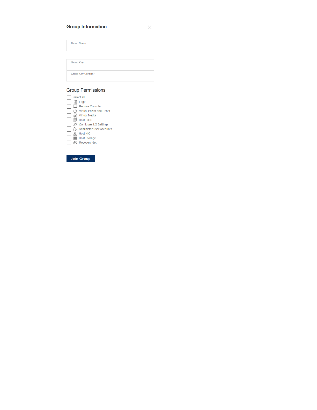
3. Enter the following information:
• Group Name—The group name, which can be 1 to 31 characters long.
• Group Key—The group password, which can be from the configured minimum
password length to 31 characters long.
• Group Key Confirm—Confirm the group password.
If you enter the name and key for an existing group, the local iLO system is added to that
group. If you enter the name and key for a group that does not exist, the group is created
and the local iLO system is added to the new group.
4. Select from the following privileges:
• Login
• Remote Console
• Virtual Power and Reset
• Virtual Media
• Host BIOS
• Configure iLO Settings
• Administer User Accounts
• Host NIC
• Host Storage
• Recovery Set
The privileges granted to the group by the local iLO system control the tasks that users of
other iLO systems in the group can perform on the managed server.
5. Click Join Group.
87
Page 94
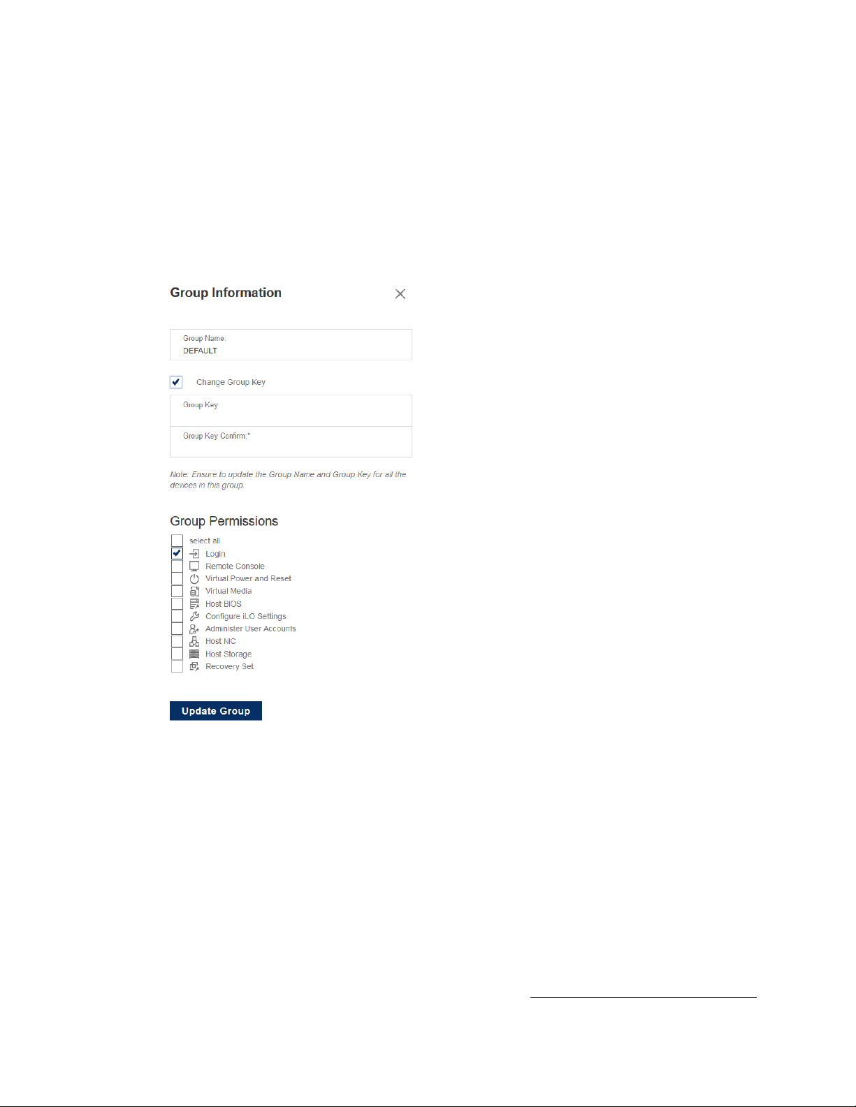
Editing iLO Federation group memberships
Prerequisites
Configure iLO Settings privilege
Procedure
1. Click iLO Federation in the navigation tree.
The Setup tab displays the existing group memberships for the local iLO system.
2. Select a group membership, and then click Edit.
3. To change the group name, enter a new name in the Group Name box.
The group name can be 1 to 31 characters long.
4. To change the group key, select the Change Group Key check box, then enter a new value in
the Group Key and Group Key Confirm boxes.
The group key can be from the configured minimum password length to 31 characters long.
5. Select or clear the check boxes for the privileges you want to update.
The privileges granted to the group by the local iLO system control the tasks that users of
other iLO systems in the group can perform on the managed server.
6. For more information about the available privileges, see iLO Federation group privileges .
7. Click Update Group.
88
Page 95

8. If you updated the group name or group key, update them on the other systems in the
affected group.
Removing a local iLO system from an iLO Federation group
Prerequisites
Configure iLO Settings privilege
Procedure
1. Click iLO Federation in the navigation tree.
The Setup tab shows the group membership for the local iLO system.
2. Select the check box next to the group membership that you want to delete.
3. Click Delete.
4. When prompted to confirm the request, click OK.
89
Page 96
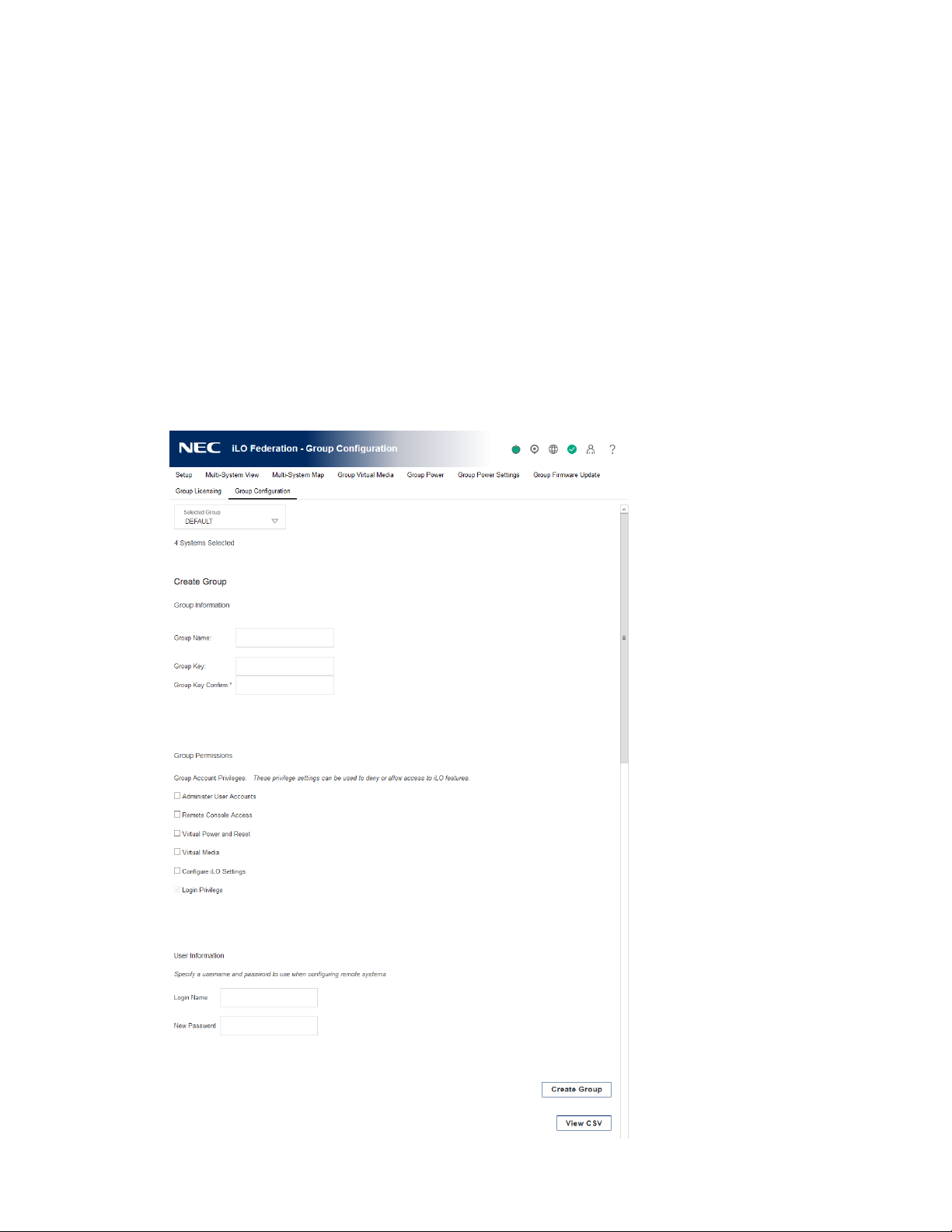
Adding iLO Federation group memberships (multiple iLO systems)
Adding an iLO Federation group based on an existing group
Use this procedure to create an iLO Federation group with the same members as an existing
group. For example, you might want to create a group that contains the same systems that are in
the DEFAULT group, but with different privileges.
Prerequisites
• Configure iLO Settings privilege
• An iLO license that supports this feature is installed.
Procedure
1. Click iLO Federation in the navigation tree, and then click the Group Configuration tab.
90
Page 97

If no iLO Federation groups exist, this page displays the following message: There are no
configured groups. Use the iLO Federation Setup page to create a group.
2. Select a group from the Selected Group menu.
All of the systems in the selected group will be added to the group you create on this page.
3. Enter the following information:
• Group Name—The group name, which can be 1 to 31 characters long.
• Group Key—The group password, which can be from the configured minimum
password length to 31 characters long.
• Group Key Confirm—Confirm the group password.
If you enter the name of a group that exists, iLO prompts you to enter a unique group name.
4. Select from the following privileges:
• Administer User Accounts
• Remote Console Access
• Virtual Power and Reset
• Virtual Media
• Configure iLO Settings
• Login Privilege
This step defines the privileges that members of the group have for configuring the other
members of the group.
5. Optional: Enter the Login Name and Password for a user account on the remote systems
you want to manage.
This information is required if the selected group does not have the Configure iLO Settings
privilege on the remote systems you want to manage.
To enter credentials for multiple remote systems, create a user account with the same login
name and password on each system.
6. Click Create Group.
The group creation process takes a few minutes. The group will be fully populated within the
amount of time configured for the Multicast Announcement Interval.
Creating a group from a filtered set of servers
Use this procedure to create an iLO Federation group from a list of filtered servers. For example,
you might want to create a group that contains all servers with a specific version of the iLO
firmware.
When you create a group from a list of filtered servers, only the servers listed in the Affected
Systems list at the time the group is created are added to the group. If you configure servers
that meet the filter criteria after the group is created, they are not added to the group.
91
Page 98

Prerequisites
• Configure iLO Settings privilege
• An iLO license that supports this feature is installed.
Procedure
1. Create a set of systems by using the filters on the iLO Federation pages.
2. Click iLO Federation in the navigation tree, and then click the Group Configuration tab.
3. Select a group from the Selected Group menu.
4. Enter the following information:
The filters you apply when you create a set of systems are listed at the top of the page. To
remove a filter, click the filter name.
If no iLO Federation groups exist, this page displays the following message: There are no
configured groups. Use the Setup page to create a group.
All of the systems in the selected group that meet the selected filter criteria will be added to
the new group.
• Group Name—The group name, which can be 1 to 31 characters long.
• Group Key—The group password, which can be from the configured minimum
password length to 31 characters long.
• Group Key Confirm—Confirm the group password.
5. Select from the following privileges:
• Administer User Accounts
• Remote Console Access
• Virtual Power and Reset
• Virtual Media
• Configure iLO Settings
• Login Privilege
For more information about the available privileges, see iLO Federation group privileges.
This step defines the privileges that members of the group have for configuring the other
members of the group.
6. Optional: Enter the Login Name and Password for a user account on the remote systems
you want to manage.
This information is required if the selected group does not have the Configure iLO Settings
privilege on the remote systems you want to manage.
To enter credentials for multiple remote systems, create a user account with the same login
name and password on each system.
7. To save the configuration, click Create Group.
The group creation process takes a few minutes. The group will be fully populated within the
amount of time configured for the Multicast Announcement Interval.
92
Page 99

Servers affected by a group membership change
The Affected Systems section on the Group Configuration page provides the following details
about the servers affected when you make a group membership change:
• Server Name—The server name defined by the host operating system.
• Server Power—The server power state (ON or OFF).
• UID Indicator—The state of the UID LED. The UID LED helps you identify and locate a server,
especially in high-density rack environments. The possible states are UID ON, UID OFF, and
UID BLINK.
• iLO Hostname—The fully qualified network name assigned to the iLO subsystem. To open
the iLO web interface for the server, click the link in the iLO Hostname column.
• IP Address—The network IP address of the iLO subsystem. To open the iLO web interface
for the server, click the link in the IP Address column.
Click Next or Previous (if available) to view more servers in the list.
More Information
Exporting iLO Federation information to a CSV file
93
Page 100

Using the iLO Federation features
Selected Group list
All of the iLO Federation pages except for Setup have a Selected Group list. When you select a
group from the Selected Group list:
• The servers affected by a change on the Group Virtual Media, Group Power, Group
Firmware Update, Group Licensing, and Group Configuration pages are listed in the
Affected Systems table.
• The information displayed on iLO Federation pages applies to all the servers in the selected
group.
• The changes you make on iLO Federation pages apply to all the servers in the selected
group.
• The selected group is saved in a cookie and remains persistent, even when you log out of
iLO.
After you select a group, you can filter the servers in the list to view server information or
perform actions on a subset of the servers in the group.
Selected Group list filters
When you filter the list of servers:
• The information displayed on iLO Federation pages applies to all the servers in the selected
group that meet the filter criteria.
• The changes you make on iLO Federation pages apply to all the servers in the selected
group that meet the filter criteria.
• The filter settings are saved in a cookie and remain persistent, even when you log out of iLO.
Selected Group list filter criteria
You can use the following criteria to filter the servers in a group:
• Health status—Click a health status link to select servers with a specific health status.
• Model—Click a server model number link to select servers matching the selected model.
• Server name—Click a server name to filter by an individual server.
• Firmware Information—Click a firmware version or flash status to select servers matching
the selected firmware version or status.
• TPM or TM Option ROM Measuring—Click an Option ROM Measuring status to include or
exclude servers matching the selected Option ROM Measuring status.
• License usage—If an error message related to a license key is displayed, click the license key
to select servers that use that license key.
• License type—Click a license type to select servers with the selected license type installed.
• License status—Click a license status to select servers with an installed license matching the
selected status.
94
 Loading...