

Page 1

NDA-24304
ISSUE 1
STOCK # 200798
®
Hotel Feature Programming Manual
OCTOBER, 2000
NEC America, Inc.
Page 2

The informationcontained in this document is specific to D
term
Series E only.
Throughout this document, references to “Console” or “Attendant Console”
imply a Hotel Console. Most features described in this manual require a Hotel
Console. However, somefeatures(includingA-57, A-73,I-23, P-34, and V-16)
can also be performed using a Business Console.
Minimum firmware may be required. Contact NEC Engineering for additional
information.
NEC America, Inc. reserves the right to change the specifications, functions, or
features, at any time, without notice.
NEC America, Inc. has prepared this document for use by its employees and
customers. The information contained herein is the property of NEC America,
Inc. and shall not be reproduced without prior written approval from NEC
America, Inc.
NEAX
®
and D
term®
are registered trademarks of NEC Corporation.
Copyright 2000
NEC America, Inc.
Printed in the U.S.A
Page 3

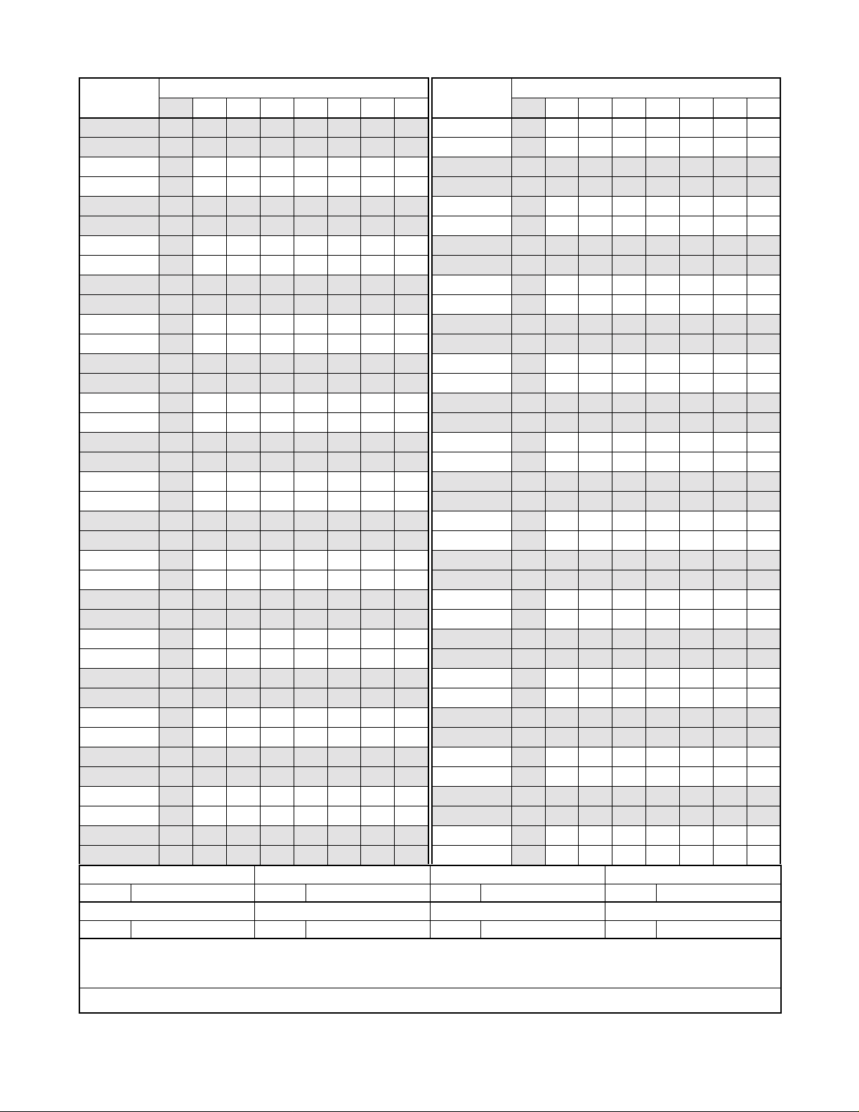
PAGE No.
i 1
ii 1
iii 1
iv 1
v 1
vi 1
vii 1
viii 1
1 1
2 1
3 1
4 1
5 1
6 1
7 1
8 1
9 1
10 1
11 1
12 1
13 1
14 1
15 1
16 1
17 1
18 1
19 1
20 1
21 1
22 1
23 1
24 1
25 1
26 1
27 1
28 1
29 1
30 1
DATE OCTOBER, 2000 DATE DATE DATE
DATE DATE DA TE DATE
12345678
ISSUE 1 ISSUE 2 ISSUE 3 ISSUE 4
ISSUE 5 ISSUE 6 ISSUE 7 ISSUE 8
ISSUE No.
PAGE No.
31 1
32 1
33 1
34 1
35 1
36 1
37 1
38 1
39 1
40 1
41 1
42 1
43 1
44 1
45 1
46 1
47 1
48 1
49 1
50 1
51 1
52 1
53 1
54 1
55 1
56 1
57 1
58 1
59 1
60 1
61 1
62 1
63 1
64 1
65 1
66 1
67 1
68 1
12345678
ISSUE No.
NEAX2400 IPX
Hotel Feature Programming Manual
Revision Sheet 1/4
NDA-24304
Page 4
PAGE No.
69 1
70 1
71 1
72 1
73 1
74 1
75 1
76 1
77 1
78 1
79 1
80 1
81 1
82 1
83 1
84 1
85 1
86 1
87 1
88 1
89 1
90 1
91 1
92 1
93 1
94 1
95 1
96 1
97 1
98 1
99 1
100 1
101 1
102 1
103 1
104 1
105 1
106 1
DATE OCTOBER, 2000 DATE DATE DATE
DATE DATE DA TE DATE
12345678
ISSUE 1 ISSUE 2 ISSUE 3 ISSUE 4
ISSUE 5 ISSUE 6 ISSUE 7 ISSUE 8
ISSUE No.
PAGE No.
107 1
108 1
109 1
110 1
111 1
112 1
113 1
114 1
115 1
116 1
117 1
118 1
119 1
120 1
121 1
122 1
123 1
124 1
125 1
126 1
127 1
128 1
129 1
130 1
131 1
132 1
133 1
134 1
135 1
136 1
137 1
138 1
139 1
140 1
141 1
142 1
143 1
144 1
12345678
ISSUE No.
NEAX2400 IPX
Hotel Feature Programming Manual
Revision Sheet 2/4
NDA-24304
Page 5

PAGE No.
145 1
146 1
147 1
148 1
149 1
150 1
151 1
152 1
153 1
154 1
155 1
156 1
157 1
158 1
159 1
160 1
161 1
162 1
163 1
164 1
165 1
166 1
167 1
168 1
169 1
170 1
171 1
172 1
173 1
174 1
175 1
176 1
177 1
178 1
179 1
180 1
181 1
182 1
DATE OCTOBER, 2000 DATE DATE DATE
DATE DATE DA TE DATE
12345678
ISSUE 1 ISSUE 2 ISSUE 3 ISSUE 4
ISSUE 5 ISSUE 6 ISSUE 7 ISSUE 8
ISSUE No.
PAGE No.
183 1
184 1
185 1
186 1
187 1
188 1
189 1
190 1
191 1
192 1
193 1
194 1
195 1
196 1
197 1
198 1
199 1
200 1
201 1
202 1
203 1
204 1
205 1
206 1
207 1
208 1
209 1
210 1
211 1
212 1
213 1
214 1
215 1
216 1
217 1
218 1
219 1
220 1
12345678
ISSUE No.
NEAX2400 IPX
Hotel Feature Programming Manual
Revision Sheet 3/4
NDA-24304
Page 6

PAGE No.
221 1
222 1
223 1
224 1
225 1
226 1
227 1
228 1
229 1
230 1
231 1
232 1
233 1
234 1
235 1
236 1
237 1
238 1
ISSUE No.
12345678
PAGE No.
ISSUE No.
12345678
ISSUE 1 ISSUE 2 ISSUE 3 ISSUE 4
DATE OCTOBER, 2000 DATE DATE DATE
ISSUE 5 ISSUE 6 ISSUE 7 ISSUE 8
DATE DATE DA TE DATE
NEAX2400 IPX
Hotel Feature Programming Manual
Revision Sheet 4/4
NDA-24304
Page 7

NDA-24304
ISSUE 1
OCTOBER, 2000
NEAX2400 IPX
Hotel Feature Programming Manual
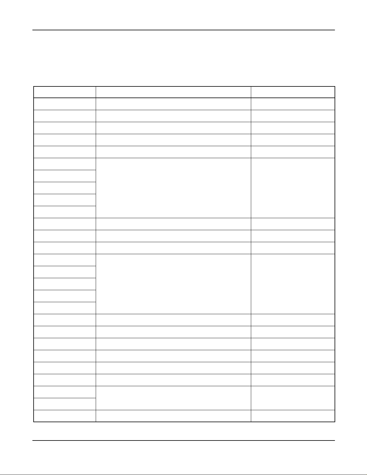
Feature List
Page
Introduction.............................................................. 1
NumberingPlan .......................................................... 3
DescriptionofServiceFeatures.............................................. 13
A-10 AutomaticWake-Up............................................... 15
A-10D Automatic Wake-Up D
A-15 AnnouncementService ............................................ 38
A-25 Attendant Console With Hotel Functions ............................... 40
A-26 AuditReports .................................................... 49
A-48 AutomaticMessageWaitingLampOff................................. 52
A-57 AlertService..................................................... 54
A-58 Automatic Wake-up - Hotel Attendant . ................................ 57
A-73 AutomaticMultipleAttendantRecall .................................. 60
A-74 Answering Camp-On/Call Hold Calls By Switchhook Flash ................. 62
A-75 AutomatedGuestStationVoiceMailRetrieval .......................... 64
B-26 Busy Status - Hotel Attendant . . . .................................... 66
C-19 CalendarDisplay ................................................. 69
C-23 Check-In/Checkout................................................ 70
C-32 Calling Station Number Display . . .................................... 72
C-71 Called Number Display - Hotel Attendant Console . ...................... 74
C-72 ConnectingRoomService .......................................... 77
C-147 CallInformationDisplay............................................ 81
D-11 DoNotDisturb ................................................... 83
D-11D Do Not Disturb - D
D-15 Day/NightClassofService ......................................... 94
D-23 DirectPageConnection............................................ 97
D-24 DirectPaging .................................................... 100
D-25 DirectServiceSet/Reset ........................................... 101
D-26 DirectStationSelection ............................................ 103
D-88 DirectoryAssistanceInterface ....................................... 104
D-89 DirectSelection-Outside .......................................... 106
D-105D D
term
WithHotelFunction .......................................... 107
D-107 DirectDataEntry-Station .......................................... 111
D-150 DoubleSuiteRoom ............................................... 112
D-151 DD/MWLampControl ............................................. 116
E-21 Emergency Call Monitor - Attendant . . ................................ 117
G-1 Guest/AdministrativeService........................................ 121
term
.......................................... 26
term
............................................. 89
NEAX2400 IPX Hotel Feature Programming Manual
NDA-24304, Issue 1
Page i
Page 8

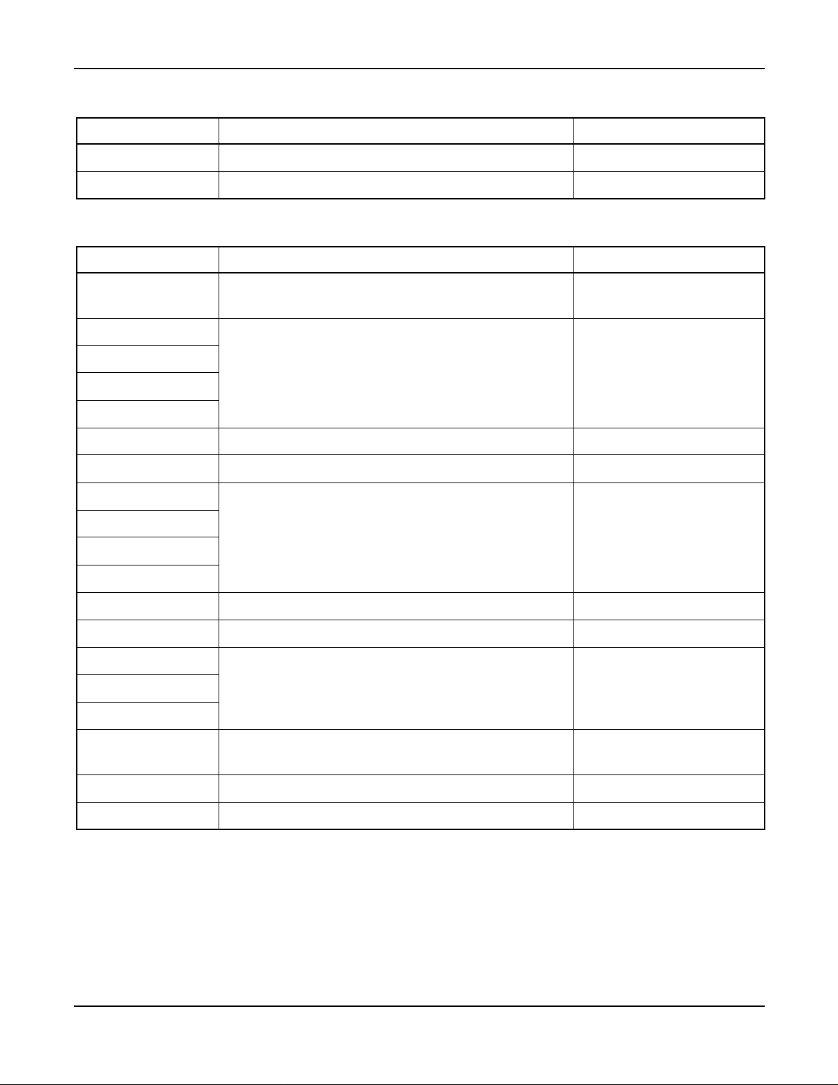
Feature List (Continued)
Page
G-4 GroupServiceThroughPMS........................................ 123
G-5 GuestNameDisplayThroughPMS................................... 127
G-6D Guest Name Display - D
G-7D Guest Information Display - D
term
......................................... 128
term
.................................... 135
G-8 Guest Information Display - Hotel Attendant Console . . . .................. 138
G-9 GuestInformationDisplay-PMSTerminal ............................. 141
G-11 Guest Room Calling - Hotel Attendant . ................................ 144
G-21 GroupRestriction................................................. 147
G-24 Guest Station - D
term
.............................................. 154
H-8 House Phone/Hot Line ............................................. 156
H-22 HotelFeatureTransparencyOverCCIS ............................... 157
I-23 Inter-PositionTransfer2............................................ 163
L-27 Language Service . . .............................................. 164
M-6 MessageWaiting ................................................. 169
M-22 MaidStatus ..................................................... 172
M-51 Manual Switching Of C.O. Incoming Call Destination . . . .................. 178
M-68 MaidStatus-Answerback .......................................... 179
O-6 Off-hookAlarm................................................... 182
O-9 OvertimeCall .................................................... 186
P-8 PrinterControl-HotelAttendantConsole .............................. 187
P-27 PMSInterface-BISYNC ........................................... 193
P-29 PMSInterface ................................................... 196
P-34 PagingConsole .................................................. 203
R-9 RoomCutoff..................................................... 206
R-10 RoomStatus .................................................... 209
R-17 RoomNumbering................................................. 212
S-17 SplitAccesstoOutgoing ........................................... 214
S-32 Screening....................................................... 216
S-49 ServiceCallRouting............................................... 218
S-74 SecretarialService-GuestStation ................................... 219
S-75 SuiteRoomService ............................................... 222
S-128 2ndWake-upCall-SameGuestStation............................... 227
T-13 TollTerminalAccess .............................................. 231
T-21 TimingStart ..................................................... 232
V-16 VoiceMailServiceViaMessageCenterInterface(MCI)................... 235
W-2 Wake-up Announcement - Headstart . . ................................ 237
Page ii NDA-24304, Issue 1
NEAX2400IPX HotelFeatureProgramming Manual
Page 9

List of Figures
Page
Figure1 KeyAllocationsofDeskConsole................................... 41
Figure 2 Display Area of Attendant Console and Desk Console .................. 74
Figure 3 Console Lamps Used for Connecting Suites.......................... 78
Figure 4 Key Pattern on the Attendant Console . . . ........................... 101
Figure5 KeyPatternontheDeskConsole.................................. 101
Figure 6 Example of 16-Button D
term
onaFrontDeskConsole.................. 108
Figure 7 Example of Single/Double Suite Room . . . ........................... 112
Figure 8 LCD Display on Special Administration Station D
term
................... 128
Figure 9 DSS Key/Station Correspondence and Lamp Indications. . . ............. 144
Figure 10 Example of Display for Call Origination - from Attendant
ConsoleandDeskConsole....................................... 157
Figure 11 Example of Display for Call Origination from D
term
..................... 157
Figure 12 Call Termination on Attendant Console, Desk Console,
and Special Administration D
term
................................... 158
Figure 13 Example of Service Feature Setting - Attendant Console
andDeskConsole.............................................. 158
Figure 14 Check-In/Checkout Keys Replaced by Secretary Service
Set/Reset(SCS,SCR)........................................... 221
Figure 15 DSS B usy Lamps on Attendant Console and Desk Console. ............. 223
NEAX2400 IPX Hotel Feature Programming Manual
NDA-24304, Issue 1
Page iii
Page 10

List of Tables
Page
Table1 DialAccessNumbersforAdministrationStation....................... 3
Table2 DialAccessNumbersforGuestStation ............................. 3
Table3 SpecialServiceAccessNumbers.................................. 4
Table4 TrunkAccessNumbers.......................................... 5
Table5 DialAccessNumberingPlanforAdministrationStation................. 6
Table6 DialAccessNumberingPlanforGuestStation........................ 7
Table 7 Key Arrangement for Hotel Attendant Console . . ...................... 48
Table8 AuditReport................................................... 49
Table 9 Standard Service Abbreviations on D
term
............................ 109
Table10 AvailableHospitalityServiceOverCCIS............................. 159
Table11 TextExplanations.............................................. 199
Page iv NDA-24304, Issue 1
NEAX2400IPX HotelFeatureProgramming Manual
Page 11

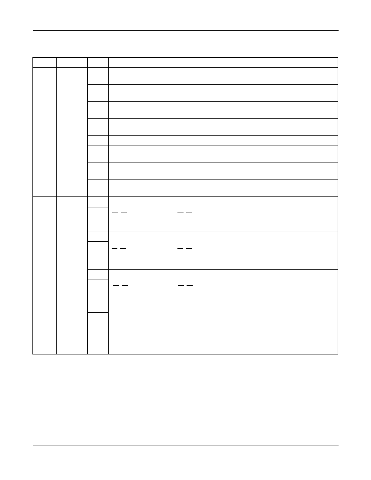
NEAX2400 IPX Hotel Features
LEGEND
X – Available
— – Not Applicable
N – Not Available
→ – Feature carried over to next software series
Index Feature Description
A-10 Automatic Wake-Up
A-10D Automatic Wake-Up D
term
A-15 Announcement Service
A-25 Attendant Console With Hotel Functions
A-26 Audit Reports
Non-
Network
XX
XX
X
X
XX
FCCS
—
N
A-48 Automatic Message Waiting Lamp Off XX
A-57 Alert Service
A-58 Automatic Wake-up - Hotel Attendant
A-73 Automatic Multiple Attendant Recall
A-74 Answering Camp-On/Call Hold Calls By Switchhook Flash
A-75 Automated Guest Station Voice Mail Retrieval
X
XX
X
X
X —
N
N
—
B-26 Busy Status - Hotel Attendant
C-19 Calendar Display
C-23 Check-In/Checkout
C-32 Calling Station Number Display
C-71 Called Number Display - Hotel Attendant Console
XX
X
XX
XX
XX
C-72 Connecting Room Service X N
C-147 Call Information Display
D-11 Do Not Disturb
term
D-11D
Do Not Disturb - D
Note: Different from Business Feature.
X N
XX
XX
D-15 Day/Night Class of Service X N
D-23 Direct Page Connection
D-24 Direct Paging
D-25 Direct Service Set/Reset
D-26 Direct Station Selection
D-88 Directory Assistance Inter face
D-89 Direct Selection - Outside
term
D-105D D
With Hotel Function XX
D-107 Direct Data Entry - Station
X —
X
XX
X
X
X —
X
—
—
—
N
N
NEAX2400 IPX Hotel Feature Programming Manual
NDA-24304, Issue 1
Page v
Page 12

NEAX2400 IP X Hotel Features (Continued)
LEGEND
X – Availab le
— – Not Applicable
N – Not Available
→ – Feature carried over to next software series
Index Feature Description
D-150 Double Suite Room
D-151 DD/MW Lamp Control
E-21 Emergency Call Monitor - Attendant
G-1 Guest/Administrative Service
G-4 Group Service Through PMS
Non-
Network
X
XX
X
XX
XX
FCCS
N
N
G-5 Guest Name Display Through PMS XX
G-6D Guest Name Display - D
G-7D Guest Information Display - D
G-8 Guest Information Display - Hotel Attendant Console
G-9 Guest Information Display - PMS Terminal
G-11 Guest Room Calling - Hotel Attendant
term
term
XX
X
X
X
XX
N
N
N
G-21 Group Restriction X N
G-24 Guest Station - D
term
H-8 House Phone/Hot Line
H-22 Hotel Feature Transparency Over CCIS
I-23 Inter-Position Transfer 2
L-27 Language Service
XX
X
X
X
XX
—
—
N
M-6 Message Waiting XX
M-22 Maid Status XX
M-51 M anual Switching Of C.O. Incoming C all Destination
M-68 M aid S tatus - Answerback
O-6 Off-hook Alarm
O-9 Overtime Call
X
X
XX
XX
N
N
P-8 Printer Control - Hotel Attendant Console XX
P-27 PMS Interface - BISYNC XX
P-29 PMS Interface
P-34 P aging Console
R-9 Room Cutoff
R-10 Room Status
XX
X
XX
XX
—
R-17 Room N umbering X —
S-17 S plit Access to Outgoing
NEAX2400IPX HotelFeatureProgramming Manual
Page vi NDA-24304, Issue 1
XX
Page 13

NEAX2400 IP X Hotel Features (Continued)
LEGEND
X – Availab le
— – Not Applicable
N – Not Available
→ – Feature carried over to next software series
Index Feature Description
S-32 Screening
S-49 S ervice Call Routing
S-74 Secretarial Service - Guest Station
S-75 S uite Room Service
S-128 2nd Wake-up Call - Same Guest S tation
Non-
Network
X
XX
X
X
XX
FCCS
N
N
N
T-13 Toll Terminal Access XX
T-21 Timing Start XX
V-16 Voice Mail Service Via Message Center Interface (MCI)
W-2 Wake-up Announcement - Headstart
XX
X
N
NEAX2400 IPX Hotel Feature Programming Manual
NDA-24304, Issue 1
Page vii
Page 14

This page is for your notes.
Page viii NDA-24304, Issue 1
NEAX2400IPX HotelFeatureProgramming Manual
Page 15

Introduction
Introduction
General Description
This manual explains the Office Data Design of the Hotel System, the Numbering Plan and a description of Service
features.
How to Follow the Manual
This manual is organized as follows:
• Numbering Plan
This section explains the numbering plan in the hotel system.
• Description of Service Features
This section explains how to use the hotel service features.
NEAX2400 IPX Hotel Feature Programming Manual
NDA-24304, Issue 1
Page 1
Page 16

This page is for your notes.
Page 2 NDA-24304, Issue 1
NEAX2400IPX HotelFeatureProgramming Manual
Page 17

Numbering Plan
Numbering Plan
Access Codes for various service features are determined according to the Dial Access Num bering Plan. This
chapter explains the Numbering Plan, and commands related to the Numbering Plan in the Hotel System.
Three types of Dial Access Numbers
• Station Access Numbers
• SpecialService Access Numbers
• Trunk Access Numbers
Basic Knowledge of Dial Access Numbers
This section explains the procedure for determining these Dial Access numbers and precautions.
1. A Dial Access Number consists of an Access Level and a Number of Digits as shown below:
Number of Digits (maximum 6 digits)
ABCDEFDial Access Number:
Access Level (0 through 9, *, #)
2. For Hotel Systems, the service to be performed is determined according to the specific Dial Access
Number.
3. The Hotel System can have two Num bering Plan Development tables; one is for Administration stations
and the other for Guest stations. Therefore, the D ial Access Number for Administration stations and the
Dial Access Number for Guest stations can be provided independently. For example:
• Dial Access Numbers for Administration Station
Table 1 Dial Access Numbers for Administration Station
DIAL ACCESS NUMBER ACCESS TO
“0” Split Access To Outgoing (Operator Call)
“10” Speed Calling - System
“12” Call Hold
“2XXXX” Guest Station (4 or 5 digits) of Main Building
“3XXXX” Guest Station (4 or 5 digits) of Annex
“4XXX” Administration Station (4 digits)
“5XXX” Special Administration (4 digits)
“8X” 2-Digits Trunk
“9” C.O. Trunk
“6” and “7” Vacant Level
• Dial Access Numbers for Guest Station
Table 2 Dial Access Numbers for Guest Station
DIAL ACCESS NUMBER ACCESS TO
“0” Split Access To Outgoing (Special Administration Station (STN 5000) Call
NEAX2400 IPX Hotel Feature Programming Manual
NDA-24304, Issue 1
Page 3
Page 18

Numbering Plan
Table 2 Dial Access Numbers for Guest Station (Continued)
DIAL ACCESS NUMBER ACCESS TO
“13” Automatic Wake Up; Set
“14” Automatic Wake Up; Cancel
“2XXXX” Guest Station (4 or 5 digits) of Main Building
“3XXXX” Guest Station (4 or 5 digits) of Annex
“7” Floor Service
“9” C.O. Trunk
“4”, “5”, “6”, and “8” Vacant Level
Note: For the Access Level (1st digit of the Dial Access numbers) different numbers are assigned for Station
Access numbers, Special Service Access numbers, and Trunk Access numbers.
Station Access Numbers
1. One through six-digit station numbers are supported.
2. The NEAX2400 IPX can provide Timing Start Service. The Timing Start Service allows single-digit and
multi-digit stations to use the same Access levels. For example:
2101: Guest Station Num ber of No. 1 Room on the 1st floor of the main building.
21001: Guest Station Number of No. 1 Room on the 10th floor of the main building.
3101: Guest Station Num ber of No. 1 Room on the 1st floor of the annex.
31001: Guest Station Number of No. 1 Room on the 10th floor of the annex.
3. The same station number cannot be assigned twicewithin the same NEAX2400 IPX, even if it is assigned
to different tenants or to an Administration Station and a Guest Station.
Special Service Access N umbers
1. SpecialService Accessnumbers of one through six digits can be assigned for each Access Level. Usually,
one through three digits are used.
2. The Hotel System can provide the Same Number Access (Split Access To Outgoing) service. The Same
Number Access service can provide both Administration and Guest stations with the different service
featureby the samenumber. It c an also providethe same ora differentservice featureby the same number
according to Tenant Class, Route Restriction Class (RSC) and Service Feature Class (SFC) concerned.
Table 3 Special Service Access Numbers
DIAL
CODE
SERVICE FEATURE FO R
ADMINISTRATION STATION
SERVICE FEATURE FO R
GUEST STATION
“0” Operator Call Special Administration Station Call
3. The Hotel System can provide the Floor Service. The Floor Service is a service to call the Room Service
station on each floor by the same Access code. For example:
• Guest Station on the 1st Floor of the main building:
dial “7” Calling
→ Room S ervice Station (STN 4801) on the 1F
• Guest Station on the 2nd Floor of the main building
dial “7”
→ Calling Room Service Station (STN 4802) on the 2F
• Guest Station on the 3rd Floor of the main building
dial “7”
→ Calling Room Service Station (STN 4803) on the 3F
Table 4 shows a listing of special services which require Access numbers.
Page 4 NDA-24304, Issue 1
NEAX2400IPX HotelFeatureProgramming Manual
Page 19

Numbering Plan
Note: In a case where both Entry and Cancel are specified for the same special service, different Access numbers
must be assigned for Entry and for Cancel.
Trunk Access Numbers
1. Trunk Access numbers ranging from one through six (1-6) digits may be assigned on an individual basis.
Usually, 1-3 digits are used.
Table 4 Trunk Access Numbers
NAME OF SPECIAL SERVICE NAME OF SPECIAL SERVICE
Account Code Dial C all Forwarding - D on’t Answer - Cancel
Attendant Manual Override Call Hold
Authorization Code/Forced Account Code Dial Call Park Access Code
Automatic Wake Up - Set Call Park Local Retrieval Code
Automatic Wake Up - Cancel Call Park Remote Retrieval Code
Busy Out - Entry (UCD) Call Pickup
Busy Out - Cancel (UCD) Call Pickup - Direct
Call Back - Entry Call Waiting
Call Back - Cancel Data Privacy - Entry
Call Forwarding - All Calls - Entry Data Privacy - Cancel
Call Forwarding - All Calls - Cancel Dial Access to Attendant
Call Forwarding - Busy Line - Entry Executive Right-of-Way
Call Forwarding - Busy Line - Cancel Faulty Trunk Report
Call Forwarding - Don’t Answer - Entry Flash Signal Sending (CAS Main Station)
Floor Service Priority Call 1
Group Announcement - Entry Priority Call 2
Group Announcement - Cancel Priority Call 3
Guest/Administration Service Priority Paging
Hotel Service Speed Calling Access
Individual Speed Calling: Entry Same Number Access
Individual Speed Calling: Access TAS Answer
Individual Trunk Access Trunk Queuing: Entry
Line Load Control: Entry Trunk Queuing: Cancel
Line Load Control: Cancel Voice Call
Message Reminder
2. Trunk Access numbers are required on an individual route basis.
NEAX2400 IPX Hotel Feature Programming Manual
NDA-24304, Issue 1
Page 5
Page 20
Numbering Plan
3. When Least Cost R outing (LCR) is utilized, LCR Access is regarded as access to an individual route;
therefore an Access Number must be assigned.
4. If Answer Service is provided for Speaker and/or Radio Paging, a Paging Answer code must be assigned.
Examples of a Dial Access Numbering Plans are shown in Table 5 and Table 6.
Table 5 Dial Access Numbering Plan for Administration Station
ACCESS NUMBER FUNCTION REMARKS
0 Same Number Access (Dial Access to Attendant) Operator Call
10 Call Hold
11 Call Back (Entry) Cancel Number is “19”
12 Executive Right-of-Way
13 Speed Calling System
14
15
16
Vacant Numbers
17
18
19 Call Back (Cancel) Entry Number is “11”
2000 - 2018 4-digit Administration Station Number
3000 - 3011 4-digit Guest Station Number
4
5
6
Vacant Numbers
7
80 Vacant Numbers
81 Access to Area A Route Number: 2
82 Access to Area B R oute Num ber: 3
83 Access to Area C R oute Num ber: 4
84 Access to Area D Route Number: 5
85 Access to Area E Route Number: 6
86
Vacant Numbers
87
88 Access to Paging Equipment Route Number: 10
Page 6 NDA-24304, Issue 1
NEAX2400IPX HotelFeatureProgramming Manual
Page 21
Numbering Plan
Table 5 Dial Access Numbering Plan for Administration Station (Continued)
ACCESS NUMBER FUNCTION REMARKS
89 Vacant Number
9 Access to Central Office Route Number: 1
Table 6 Dial Access Numbering Plan for Guest Station
ACCESS NUMBER FUNCTION REMARKS
0
Same Number Access (Special Administration Station
Call)
Special Administration
Station Number “2000”
10
11
Vacant Numbers
12
13
14 Automatic Wake Up (Entry) Cancel Number is “15”
15 Automatic Wake Up (Cancel) Entry Number is “14”
16
17
Vacant Numbers
18
19
2 Vacant Level
3000 - 3011 4-digit Guest Station Number
4
Vacant Level5
6
7 Floor Service
IF: STN = 2001 Call
2F: STN = 2002 Call
8 Vacant Level
9 Access to Central Office Route Number: 1
Commands Related to the Numbering Plan
This section explains the commands related to the Numbering Plan and also explains comm and assignment
procedure. For details of a specific command, refer to the NEAX2400 IPX Office Data Specification Manual.
1. ASYD (Assignment of System Data) - The system data pertaining to the Numbering Plan is as follows:
a.) SYS1 INDEX 160 b
- This data is for determining whether the Num bering Plan De velopment
6
Table is to be provided in common or separately for Administration and Guest stations. The
commands to be used vary with the value assigned to the data as follows.
NEAX2400 IPX Hotel Feature Programming Manual
NDA-24304, Issue 1
Page 7
Page 22

Numbering Plan
b.) When the Table is to be provided in common for Administration and Guest stations.
=1)
(b
6
AANP
(Common)
AASP
(Common)
ASPS (Common)
ASPF (Common)
AAST (for Administration)
AGST (for Guest)
c.) When the Table is to be provided separately for Administration and Guest stations.
=0)
(b
6
AANP
(for Admin.)
AASP
(for Admin.)
AAST
ASPS (Common)
ASPF (Common)
(for Admin.)
AGNP
(for Guest)
AGSP
(for Guest)
AGST
(for Guest)
Note: Administration stations can call Guest stations, butcalls from Guest stations to Administration stations are
restricted. A call from a Guest Station to a predetermined Administration Station is allowed via Same
Number Access (Split Access To Outgoing) service.
d.) SYS1 INDEX 161 b
6,b7
b6: “#” code is used in Timing Start Service.
(0/1 = Ineffective/Effective)
b7: “*” code is used in Timing Start Service.
(0/1 = Ineffective/Effective)
When Timing Start is used, the NEAX2400 IPX can have the following numbering:
Floor Room No. Station No.
1st 11 8111
11th 11 81111
In this case, if a 5-digit station number is dialed, the call is immediately connected to the called
station.However, ifa 4-digit station numberis dialed,the callis connectedto the called stationwith
a certain delay. This is because the necessary number of digits of the access level assigned by the
AANP/AGNP command is se t to the number of digits of station number of larger number of digits.
Thus, when a station number of smaller number of digits is dialed, the call is not connected to the
called station until the Register Inter-Digit Timer in the NEAX2400 IPX is timed out. In order that
a call by dialing a station number of smaller number of digits can be immediately connected to the
called station, assignment of this system data is necessary. If use of “#” code is made effective, a
call to a station of smaller number of digits is connected immediately to the called station with “#”
code dialed after the station number.
2. AANP/AGNP (Assignment of Administration Numbering Plan/Assignment of Guest Numbering Plan) These commands are used to assign theminimum requirednumber of digits to be usedfor determiningthe
required service according to the first digit received.
Page 8 NDA-24304, Issue 1
NEAX2400IPX HotelFeatureProgramming Manual
Page 23

Numbering Plan
Note: When the Timing start service is used, the minimum required number of digits is assigned to the station
number of larger number of digits.
For example, w hen Station Number 200 and Station Number 2000 exist, Number of Necessary Digits
(NND) = 4 is to be assigned with respect to the 1st Digit (1st DC) = 2.
3. Adummy number (SID36,STATE 63) is necessary for the followingcase: When the NEAX2400 IPX has
stations “200” and “21000”, assign a dummy number for “210” with NND = 2.
4. AASP/AGSP (Assignment of Administration Special Access Code/Assignment of Guest Special Access
Code) - These commands are used tospecify the kind of service to be executedor the route to be accessed
when a Special Access Code or Trunk Access Code is dialed. This data pertains to Administration stations.
5. ASPS (Assignment of Special Access Code for Same Number Access) - When Split Access To Outgoing
(Same NumberAccess) is r equired, these comm ands are used to specify the kind of service to be executed
or the route to be accessed when a Special Access Code or Trunk Access Code is dialed.
6. ASPF (Assignment of Special Access Code for Floor Service) - This command is used to assign the calls
from Guest stations on each floor, and can be terminated to a service station, such as laundry service and
room service, on the same floor as the Guest Station.
7. AAST/AGST (Assignment of Adm inistration Station Data/Assignment of Guest Station Data) - These
commands are used to assign station data. When the NEAX2400 IPX provides the floor service, these
commands are used to assign floor service data with respect to Guest Room Service Station.
Examples of Numbering Plan Data Assignmen ts
The procedures for data assignment are explained in the subsequent pages.
1. Dial Access Number
a.) For Administration:
Access Code
Access To
“0” Operator Call
“100” ~ “1000” Guest Station on 1F
“200” ~ “2000” Guest Station on 2F
“3000” ~ “3500” Administration Station Num ber
“4000” S pecial Administration Station
“5000” R oom Service Station for 1F
“5001” R oom Service Station for 2F
“9” C.O. Trunk
b.) For Guest
Access Code
Access To
“0” Special Administration Station Call
“100” ~ “1000” Guest Station on 1F
“200” ~ “2000” Guest Station on 2F
“8” Floor Service
“9” C.O. Trunk
2. Others:
a.) Numbering Plan Development Table is provided separately for Administration and Guest.
b.) Use of “#” code in the Timing Start Service is made effective.
NEAX2400 IPX Hotel Feature Programming Manual
NDA-24304, Issue 1
Page 9
Page 24

Entry Procedure:
START
Numbering Plan
ASYD
AANP
SYS1
INDEX 160, b6=0
Numbering Plan Development Table is provided separately for
Administration and Guest.
INDEX 161, b
Use of “#” code in the Timing Start Service is made effective.
INDEX 165, b
Floor Service is provided.
With respect to the 1st digit code (1ST DC), assign Number of
Necessary Digits (NND) as follows.
1ST DC
01
14
24
34
44
54
91
=0
6
=1
7
NND
A
AGNP
AASP
With respect to the 1st digit code (1ST DC), assign Number of
Necessary Digits (NND) as follows.
1ST DC
NND
01
14
24
81
91
With respect to the Access Code (ACC) assign service
features as follows.
ACC SRV SID No. KIND
0 2(SSC) 57 0 0
ACC
SRV RT
9OGC1
Page 10 NDA-24304, Issue 1
NEAX2400IPX HotelFeatureProgramming Manual
Page 25

A
Numbering Plan
AGSP
ASPS
AAST
With respect to the Access Code (ACC) assign service features
as follows:
ACC
SRV SID No. KIND
0 2(SSC) 57 0 0
8 2(SSC) 56 0 -
ACC
SRV RT
9OGC1
With respect to the data assigned by AASP and AGSP,assign
service features as follows:
No.
F SRV SID STN
0 0 2(SSC) 2 0 1 STN - 4000
Assign thestation data of Administration stations. Also, assign
the data for floor service a s follows:
STN
ROOM CLASS
“3000” ~ “3500” 0
“4000” 0
“5000” 1 - 7
“5001” 1 - 7
AGST
ASPF
END
NEAX2400 IPX Hotel Feature Programming Manual
NDA-24304, Issue 1
Assign the station data of Guest stations.
(STN “100” - “1000”, STN “200” - “2000”)
Assign the data related to the Room Service.
Station on each floor as follows:
No.
ANX G FLR DC
0 0 0 1 5000
0 0 0 2 5001
Page 11
Page 26

This page is for your notes.
Page 12 NDA-24304, Issue 1
NEAX2400IPX HotelFeatureProgramming Manual
Page 27

Description of Service Features
Description of Service Features
Hotel Service Features
This section explains each Hotel service feature by the following items:
General De scription
Operating P rocedure
Service Conditions
Assignment Procedure
General Description
This item explains a general description of the service feature.
Operating Procedure
This item explains the procedure to be followed for receiving a specific service feature concerned. When testing a
service feature, perform installation test work steps by referring to this item.
Service Conditions
These items explain the functional outline of a specific service feature concerned and the matter of caution
(hardware requirements, etc.) related to performance of that service feature. It is recommended that these items be
referred to for more extensive knowledge of the service feature concerned.
Assignment Procedure
This item explains the procedure of a ssigning various kinds of data required for performance of a specific service
feature concerned. When recording necessary data into Data Programming Sheets, make data entry by referring to
this item.
NEAX2400 IPX Hotel Feature Programming Manual
NDA-24304, Issue 1
Page 13
Page 28

This page is for your notes.
Page 14 NDA-24304, Issue 1
NEAX2400IPX HotelFeatureProgramming Manual
Page 29

Automatic Wake-Up A-10
A-10 Automatic Wake-Up
General Description
This service feature allows the NEAX2400 IPX to be programmed to automatically call Guest rooms at specified
times. Upon answering, the Guest is c onnected to a recorded announcement or music source. A printout of
unanswered or blocked wake-up attempts for Guest rooms is provided at the Hotel printer. This feature can be
activated from the Guest room stations, administration stations, Console, PMS Terminal, or predetermined Special
Administration Station.
Operating Procedure
To set AUTOMATIC WAKE-UP from a Guest Room
1. With separate set a nd cancel codes (24-hour time only):
a.) Lift the handset. Receive dial tone.
b.) Dial WAKE- UP code. Hear special dial tone.
c.) Dial desired time of AUTOMATIC WAKE-UP. Hear service set tone.
d.) Hang up.
2. When set and cancel codes are the same:
a.) Lift the handset. Receive dial tone.
b.) Dial WAKE- UP code. Hear special dial tone.
c.) Dial desired time of AUTOMATIC WAKE-UP. Hear service set tone.
d.) Hang up.
To cancel AUTOMATIC WAKE-UP from Guest Room
1. With separate set a nd cancel codes (24-hour time only):
a.) Lift the handset. Receive dial tone.
b.) Dial C ANCEL AUTOMATIC WAKE-UP code. Hear service dial tone.
c.) Hang up.
2. When set and cancel codes are the same:
a.) Lift the handset. Receive dial tone.
b.) Dial WAKE- UP code. Hear special dial tone.
c.) Dial the digit “3”. Hear service set tone.
d.) Hang up.
To set AUTOMATIC WAKE-UP from a Regular Administration Station
1. Only separate set a nd cancel codes will operate from a regular administration station.
a.) Lift the handset. Receive dial tone.
b.) Dial SET WAKE-UP code. Hear special dial tone.
c.) Dial desired time of AUTOMATIC WAKE-UP. Hear service set tone.
d.) Hang up.
To cancel AUTOMATIC WAKE-UP from a Regular Administration Station
1. Only separate set a nd cancel codes will operate from a regular administration station.
a.) Lift the handset. Receive dial tone.
b.) Dial C ANCEL WAKE-UP code. Hear service set tone.
c.) Hang up.
To set AUT OMATIC WAKE-UP from a S pecial Administration Station
1. Only separate set a nd cancel codes will operate from a special Administration station.
a.) Lift the handset. Receive dial tone.
NEAX2400 IPX Hotel Feature Programming Manual
NDA-24304, Issue 1
Page 15
Page 30

A-10 Automatic Wake-Up
Operating Procedure (cont’d)
b.) Dial SET WAKE-UP code. Hear special dial tone.
c.) Dial desired time of AUTOMATIC WAKE-UP, then dial the Guest room number. He ar service
set tone.
d.) Hang up.
To cancel A U TOMATIC WAKE-UP from a Special Administration Station
1. Lift the handset. R eceive dial tone.
2. Dial CANCEL WAKE-UP code and Guest room number. Hear service set tone.
3. Hang up.
To set AUTOMATIC WAKE-UP from the F ro nt Desk Terminal or Console using the WUS/WUR (Wake-Up Set/
Wake-Up Reset) key
1. When Guest calls to request a wake-up call (see DIRECT SERVICE SET/RESET [D-25]):
a.) Press the WUS key while still connected with the Guest room.
b.) Dial the wake-up time r equested. (Use of 12-hour or 24-hour time is set in system data.).
2. If the wake-up time is entered after the Guest line is released:
a.) Press WUS key. The associated lamp lights.
b.) Dial wake-up time. The console displays the entered time.
c.) Dial the Guest station number. The console displays the station number.
d.) Press the ENTER key. The lamp flashes to confirm that AUTOMATIC WAKE-UP has been set.
e.) Press the EXIT key. The lamp and station display are extinguished.
To cancel AUTOMAT IC WAKE-UP from the Front Desk T erminal or Console using the WUS/WUR (Wake-Up
Set/Wake-Up Reset) key
1. When Guest calls to cancel a wake-up call (see DIRECT SERVICE SET/RESET [D-25]):
a.) Press the WUR key while still connected with the Guest room.
2. If the wake-up cancel is input after the Guest line is released:
a.) Press WUR key. The associated lamp lights.
b.) Dial Guest station number. The console displays the station number and the AUTOMATIC
WAKE-UP time set.
c.) Press the ENTER key. The lamp flashes to confirm the cancellation of the wake-up call.
d.) Press the EXIT key. The lamp a nd station display are extinguished.
To call the Guest Station that does not answer the wak e-up call, from the Console
1. The Guest does not answer the wake-up call. The call is routed to Attendant and terminates on the WU
key.
2. Press the WU key or ANSWER key. The following is displayed:
HH:MM NAME :NANS
DEST TN:X CLS:X XXXX
No. XXXX
OCPD
3. Press the START ke y. The Guest station is rung.
4. If the Guest does not answer, release the call by pressing CANCL key. The Guest number is given to the
front desk clerk and he/she is asked to visit the Guest room.
Page 16 NDA-24304, Issue 1
NEAX2400IPX HotelFeatureProgramming Manual
Page 31

Automatic Wake-Up A-10
Service Conditions
1. From the Front Desk Terminal or Console, set AUTOMATIC WAKE-UP using either 24-hour time, or
12-hour time. When using 12-hour time, time is entered by dialing a special code, which includes either a
# or * before entering the time to indicatePM. For example, when dialing the desired time, dial #1030for
10:30 PM. The choice of # or * is assigned in system data.
2. The maximum number of stations that can set the same wake-up time can be assigned as one of the
following: 64, 128, 256, 512 stations per Local Processor (LP). If the number of stations reaches the
assigned maximum stations, the next attempt to set an AUTOMATIC WAKE-UP call at the same wakeup time is automatically set 5 minutes earlier than the appointed time.
Note 1: The ability to process this expanded number of c alls is based on traffic and station distribution in the
NEAX2400 IPX.
Note 2: Variable timing can be assigned in system data. The timing must be a multiple of five minutes (such as 5,
10, or 15) earlier.
3. All AUTOMATIC WAKE-UP times are to be set at five-minute intervals in either 12- or 24-hour time.
For example:
7:50 AM = 0750
7:55 AM = 0755
8:00 AM = 0800
Note: Wake-Up Time to be set from a station/Console w ill be rounded to the nearest multiple of five.
TIME TO BE SET BY KEYPAD OPERATION TIME TO BE SET BY THE NEAX2400 IPX
xx: x1 ~ xx: x4 xx: x0
xx: x6 ~ xx: x9 xx: x5
4. If a Wake-Up announcement is used, this feature requires one of the following hardware alternatives:
a.) Central Office Trunk (COT) or 2W E& M trunk and an announcement machine.
b.) Digital Announcement Trunk (DAT).
5. Thisfeature providesthree additional AUTOMATIC WAKE-UP attempts at fixed three-minuteintervals.
If the c alled party is not reached (no answer, busy, blocked, or locked-out) after a total of f our attempts,
the results will be automatically printed out at the hotel printer. The number of retries for a no-answer
conditionis determined by system data,up to amaximum of three retries. The number of retriesfor a busy
condition is flexible, up to a maximum of three retries.
6. Ringingduration forAUTOMATIC WAKE-UP iscontrolled by the CF/NA timer,SYS1, ASYD,INDEX
139. The choice of ring duration is made through programming in system data.
7. AUTOMATIC WAKE-UP overrides DO NOT DISTURB [D-11].
Note: For the D
term
Series E, this feature is restricted by using the DD key of the terminal.
8. AUTOMATIC WAKE-UP messages can be arranged for headstart operation. Refer to the WAKE-UP
ANNOUNCEMENT - HEADSTART [W-2] feature description for details.
9. If WAKE-UP ANNOUNCEMENT - HEADSTART [W-2] is not required, announcements can be
arranged either as continuous recordings (last party disconnects) or to automatically disconnect after 30
seconds. An engineering tra ffic study is required to determine the number of interface trunks needed to
accommodate each recording channel.
10. AUTOMATIC WAKE-UP for a Guest station can be set from the Console, predetermined Special
Administration stations, Front Desk Terminal, or the actual Guest phone. AU TOMATIC WAKE-UP for
an Administration Station c an only be set from the actual administration phone.
NEAX2400 IPX Hotel Feature Programming Manual
NDA-24304, Issue 1
Page 17
Page 32

A-10 Automatic Wake-Up
Service Conditions (cont’d)
Note: Any Administration Station that is assigned as a Special Administration Terminal may N OT set WAKE-UP
for itself or for any station other than a Guest station.
11. If PMS Language Selection is used, AUTOMATIC WAKE-UP announcements can be provided
according to a Guest's language.
12. If all announcement trunks are busy, m usic will be provided for AUTOMATIC WAKE-UP. Music is
provided by the NEAX2400 IPX MUSIC ON HOLD [M-1] source.
13. For Guest stations, a confirmation announcement can be provided instead of service set tone for
AUTOMATIC WAKE-UP setting and cancelling operations.
14. AUTOMATIC WAKE-UP entry and result information is reported, as required, to the PMS and
NEAX2400 IPX hotel printer for continuous update.
15. A maximum of six digits can be used for the identification code. Use of an ID code is not mandatory, and
is left to the customer's discretion.
16. It is possible to use the same access code for both AUTOMATIC WAKE-UP set and cancel. For example:
*1 may be assigned the AUTOMATIC WAKE-UP set and cancel access code. The NEAX2400 IPX will
recognize *1 and wait for the next digit. If *, #, 0, 1, or 2 is dialed, then a time is being set. If 3 is dialed,
this is an AUTOMATIC WAKE-UP cancel. For example:
*1 *0300 3:00 PM wake-up set (12-hour c lock)
*1 #0300 3:00 PM wake-up set (12-hour c lock)
*1 0800 8:00 AM wake-up set (12/24-hour clock)
*1 1000 10:00 AM wake-up set (12/24-hour clock)
*1 2100 9:00 P M wake-up set (24-hour clock)
*1 3 Wake-up cancel
17. As a system option, once AUTOMATIC WAKE-UP has been set from a Guest station, only that Guest
station is allowed to cancel or change the WAKE-UP service. This option is determined by system data
(Wake-Up Guest Station Priority Service).
18. These same conditions are applicable to WAKE-UP ANNOUNCEMENT - HEAD START [W-2].
19. Setting and cancelling wake-up services may be restricted, de pending on service class, from
Administration Stations, the PMS Terminal, a F ront Desk Terminal, or predetermined S pecial
Administration Stations.
20. When AUTOMATIC WA KE-UP for a Guest station is set from the Console, the PMS Terminal, a Front
Desk Terminal, or predetermined Special Administration Stations, that Guest station is allowed to set/
cancel the WAKE-UP service.
21. When AUTOMATIC WAKE-U P has been executed, setting/cancelling of another AUTOMATIC
WAKE-UP service is allowed from the Console, the PM S Terminal, a Front Desk Terminal, or
predetermined Special Administration Stations.
22. AUTOMATIC WAKE-UP [A-10] and WAKE-UP ANNOUNCEMENT-HEADSTART [W-2]
procedures remain the same.
23. Maximum number of stations per LP that can be set for a single AUTOMATIC WAKE-UP time is
determined by the system data.
24. The NEAX2400 IPX can be programmed so that, once a day, the NEAX2400 IPX will generate a nd print
a Wake-Up report listing all Wake-Ups that are currently set. The time of the output is decided by the
customer and assigned in the AHSY Command.
25. If no End Time is specified in AHSY, pending wake-up calls after 9:55 a.m. will not be printed.
Page 18 NDA-24304, Issue 1
NEAX2400IPX HotelFeatureProgramming Manual
Page 33
Automatic Wake-Up A-10
Assignment Procedure
STEP CMND BIT EXPLANATION
Don’t Disturb Override key on Console
b
0
0/1 = Out/In Service
Message Waiting Service
b
1
0/1 = Out/In Service
Language Service
b
2
0/1 = Out/In S ervice
SYS1
1
ASYD
INDEX
161
Screening
b
3
0/1 = Out/In Service
b
Not used
4
DSS (Direct Station Section) Key on Console
b
5
0/1 = Ineffective/Effective
TimingStart using “#” Code
b
6
0/1 = Ineffective/Effective
TimingStart using “*” Code
b
7
0/1 = Ineffective/Effective
b
Destination of connection when a connectionbetween Guest stations is restricted.
0
b1b
0
b
0 0 = ROT 1 0 = Announcement
1
01=ATT 11=–
b1b
0
b
Destinationof connection when Room Cutoff is assigned.
2
b3b
2
b
SYS1
2
ASYD
INDEX
162
b
b
0 0 = R OT 1 0 = Announcement
3
01=ATT 11=–
Destination of connection when Do not Disturb is assigned.
4
b5b
4
0 0 = R OT 1 0 = Announcement
5
b3b
b5b
2
4
01=ATT 11=–
b
Assignment of Answering Tone to Automatic Wake-Up Call
6
Tone to be given when a wake-up call is answered
b7b
b
7
6
b7b
6
0 0 = Music on Hold 1 0 = –
0 1 = A nnouncement 1 1 = –
NEAX2400 IPX Hotel Feature Programming Manual
NDA-24304, Issue 1
Page 19
Page 34
A-10 Automatic Wake-Up
STEP CMND BIT EXPLANATION
b
Over Time Call timer.
0
b1b
0
b
b
b
SYS1
3
ASYD
INDEX
163
b
b
0 0 = 30 min. 1 0 = 90 min.
1
0 1 = 60 min. 1 1 = 120 min.
Over Time Call
2
0/1 = Out/In Service
Over Time Call indication
3
0/1 = On Console/Hotel Printer
Step Call from Guest Station is allowed
4
0/1 = Out/In Service
Tone type for Maid Dialing
5
b6b
5
b1b
b6b
0
5
00=SST 10=MusiconHold
0 1 = Announcement 1 1 = Music on Hold
b
6
Note:
Guest Station is available. Administration Station receives only service set
tone.
Start time of Automatic Wake-Up Call
b
7
0/1: On time/5 min. before
b
Number of Digits of all Hotel ID Code
0
b
b
1
b2b1b
0
000=Notused 100=4digits
0 0 1= 1digit 1 0 1= 5digits
2
010=2digits 110=6digits
0 1 1= 3digits 1 1 1=Notused
b2b1b
0
SYS1
4
ASYD
INDEX
164
ID Code for setting/cancelling Maid Status
b
3
0/1 = Not Required/Required
b
Number of Digits of Group Code (PMS option)
4
b6b5b
b
5
4
b6b5b
4
0 0 0 = Not used 1 0 0 = 4 digits
0 0 1 = 1 digit 1 0 1 = 5 digits
b
6
0 1 0 = 2 digits 1 1 0 = 6 digits
0 1 1 = 3 digits 1 1 1 = Not used
ID Code to be entered wh en setting or cancelling Automatic Wake-Up C all from a
b
Special Administration Station
7
0/1 = Not Required/Required
Page 20 NDA-24304, Issue 1
NEAX2400IPX HotelFeatureProgramming Manual
Page 35
Automatic Wake-Up A-10
STEP CMND BIT EXPLANATION
b
Port Number of connecting the Hotel Printer Command Service
0
b
b2b1b
1
000=Port0 011=Port3
0
001=Port1 100=Port4
b
010=Port2 101=Port5
2
b2b1b
0
110=Port6
111=Port7
5
6
7
Note:
SYS1
ASYD
INDEX
165
SYS1
ASYD
INDEX
169
SYS1
ASYD
INDEX
171
Note
Hotel Printer Command Service
b
3
0/1 = Not Required/Required
Automatic Wake-Up - Hotel Attendant Assistant
b
4
0/1 = Out/In Service
Wake-UpGuest Station Priority Service
b
5
0/1 = Not P rovided/Provided
Wake-Up information (time, station number, etc.)printout
b
6
0/1 = Out/In S ervice
Floor Service
b
7
0/1 = Out/In Service
b
0
Miscellaneous Timer Counter (MTC) is to be assigned 0, a value from 0 Hex,
(0-15)
b
1
b
2
Announcement trunk release timer to reset the announcement. Availableonly with s ingle
connection. 2 sec. MTC (If MTC = 0 Hex: 30 sec.)
b
3
b
4
b
5
Assign data specifying how many minutes earlier the wake-up time for the o v erflowed
stations (more than 500/LP). 5 min. x N Hex.
b
6
b
7
b
0
b
1
b
2
b
This data designates how many times retry is allowedwhen Room Data image transfer fails
3
b
4
b
5
b
6
b
Fixed “0”
7
No more than 500 stations per LP can be set for a single Automatic Wake-Up period. If the 500 station
maximum is exceeded, the NEAX2400 IPX will automatically set the Automatic Wake-Up time five
minutes earlier for the stations subsequent to the 500th.
NEAX2400 IPX Hotel Feature Programming Manual
NDA-24304, Issue 1
Page 21
Page 36

A-10 Automatic Wake-Up
STEP CMND BIT EXPLANATION
b
Number of times of Wake-Up Answer Retry.
0
b1b
0
00=NoAnswerRetry0time
b
01=NoAnswerRetry1time
1
1 0 = No Answer Retry 2 times
1 1 = No Answer Retry 3 times
Number of characters of language information display
b
2
0/1 = 4 characters/2 characters
Restrictionfor hooking when a Guest station has originated an outgoing C.O. line call.
b
3
AHSY
8
INDEX
100
Note
0/1 = Not Required/Required
b
Type of STA for Overtime Call
4
<Overtime Call Indication of Console (SI 163, b
00:- 10: Administration STA only
01: Guest ST A only 11: Both (Administration and Guest STA)
b
5
<Overtime Call Indication on Hotel Printer (SI 163, b
3
00:- 10: Administration STA only
01:Guest STA only 11: Both (Administration and Guest STA)
Overtime Call when a station user places a C.O. trunk call
b
0 = Administration and Guest go to Console
6
1 = Guest only goes to Console
Key that means the P.M. in a case where Wake-Up time is set by the 12-hour system
b
(for Automatic Wake-Up Service).
7
0/1 = *Key/#Key
b
0
Not used
b
1
Maid Dial service from Console
b
2
0/1 = Not Required/Required
b
Not used
3
Wake-Up Time Indication on Hotel Console
b
4
0/1 = 24-hour/12-hour system
b
5
Not used
b
6
Guest Name Display on Console
b
7
0/1 = Interface Type Model 60, 90, 120/Model 90, 120
9
Note:
AHSY
INDEX
105
This entry will be the number of times the wake-up call is attempted before AHSY, INDEX 142 takes
effect.
=0)>
3
=1)>
Page 22 NDA-24304, Issue 1
NEAX2400IPX HotelFeatureProgramming Manual
Page 37

Automatic Wake-Up A-10
STEP CMND BIT EXPLANATION
b
0
b
1
Not used
b
2
b
3
Wake-Up c all “Busy” condition; transfer to Console
b
4
0/1 = Out/In S ervice
Wake-Up call “Don’t Answer” condition; transfer to Console
b
5
0/1 = Out/In S ervice
Wake-Up call “Bloc k” cond ition; transfer to Console
b
6
0/1 = Out/In S ervice
Wake-Up call for VIP B usy/Block condition; transfer to Console
b
7
0/1 = Out/In S ervice
2nd Wake-Up Call Service
b
0
0/1 = Out/In S ervice
2nd Wake-Up Call Time Indication on Console
b
1
0/1 = Out/In S ervice
2nd Wake-Up Call Cancel while Console is c onnected to the target station
b
2
0/1 = Out/In S ervice
b
Not used
3
b
ThenumberofcallsforwhichAutomaticWake-Upatthesametime(perLP)
4
b
5b4
b
0 0 = 512 calls 1 0 = 128 calls
5
b5b
4
01=64calls 11=256calls
b
The number of Retries when a Wake-Up Call encounters busy status.
6
b
7b6
b
00=3Times 10=Once
7
b7b
6
01=Twice 11=NoRetry
Daily Printout Hour
“Hour” data is assigned using a d ecimal number (Military Time).
Example: 2:00 a.m. - This data is entered as 02.
Example: 2 :30 p.m . - This data is entered as 14.
Daily Printout Minute
“Minute”data is assigned using a decimal nu mber (MilitaryTime).
Example: 2:00 a.m. - This data is entered as 00.
Example: 2 :30 p.m . - This data is entered as 30.
10
11
12
13
AHSY
INDEX
142
AHSY
INDEX
163
AHSY
INDEX
400
AHSY
INDEX
401
NEAX2400 IPX Hotel Feature Programming Manual
NDA-24304, Issue 1
Page 23
Page 38

A-10 Automatic Wake-Up
STEP CMND BIT EXPLANATION
b
Not used
0
Wake-Up Re sult (Answer) Printout
b
1
0/1 = Out/In S ervice
b
2
b
3
b
4
Not used
b
5
b
6
b
7
Specificend time, when the NEAX2400 IPX willstop scanningrooms for pendingwake-up
information.
Hour data is assigned using a decimal number (military time).
Example: 8:00 a.m. - Data entered is 08
Example: 8:30 p.m. - Data entered is 20
Specificend time, when the NEAX2400 IPX willstop scanningrooms for pendingwake-up
information.
Minute data is assigned using a decimal number (military time).
Example: 8:00 a.m. - Data entered is 00
Example: 8:30 p.m. - Data entered is 30
14
15
16
AHSY
INDEX
402
AHSY
INDEX
406
AHSY
INDEX
407
17
AANP
or
AGNP
Assign the Number of Necessary Digits for the first numeral of the Automatic Wake-Up Se rvice
Access Code.
Assign the Automatic Wake-Up S ervice Access Code.
When setting and cancelling are made by each individual Access Code.
• For Setting: CI = N, SRV = 2(SSC), SID = 48
• For Cancelling: CI = N, SRV = 2(SSC), SID = 49
18
AASP
or
AGSP
When setting and cancelling are made by the same one Access Code (for a 12-hour s ystem):CI = N,
SRV = 2(SSC), SID = 36, STATE = 33
Assign the 2nd Wake-Up service access if required.
• For Setting: CI = N, SRV = 2(SSC), SID = 36, STATE = 48
• For Cancelling: CI = N, SRV = 2(SSC), SID = 36, STATE = 50
19 ASFC
20 ARTD
Note:
Steps after ARTD are necessary only when the destination of the tone of Automatic Wake-Up call is
Note:
Allow SF I = 41 for the SFC of the stations that receive Automatic Wake-Up service (for SFI = 41,
RES = 1).
Assign route data of the trunk which interfaces with the announcement unit.
(OSGS = 2, TCL = 4)
2nd Wake-Up service can be set and/or cancelled from a Console only.
designated as Announcement Machine (See ASYD, INDEX 162).
21 ARTK Assign the trunk interfacing with the announcement unit.
Page 24 NDA-24304, Issue 1
NEAX2400IPX HotelFeatureProgramming Manual
Page 39

Automatic Wake-Up A-10
20 MBTK Release the Make Busy of the trunk assigned in ATRK.
Releasethe Call restrictions between the RSC of thestation accessing the announcement unit andthe
23 ARSC
route of the trunk assigned in ATRK.
(RRI = 2.3)
Assign the Data to the announcement unitnumber andthe route data, etc. assigned in AT RK. Assign
the information with respect to the following:
24 AAED
EQP = 16: Automatic Wake-Up Set
EQP = 18: Automatic Wake-Up Cancel
EQP = 22: Automatic Wake-Up Answer
NEAX2400 IPX Hotel Feature Programming Manual
NDA-24304, Issue 1
Page 25
Page 40

A-10D Automatic Wake-Up D
term
A-10D Automatic Wake-Up D
term
General Description
This service feature allows the NEAX2400 IPX to be programmed to automatically call Guest rooms at specified
times. Upon answering, the Guest is c onnected to a recorded announcement or music source. A printout of
unanswered, blocked, or busy wake-up attempts for Guest rooms is provided at the Hotel printer. This feature c an
be activated from the Guest room D
Operating Procedure
To set AUTOMATIC WAKE-UP from a Guest room D
1. With separate set a nd cancel codes:
a.) Lift the handset or press the SPEAKER key. Receive dial tone.
b.) Dial WAKE- UP code. Hear special dial tone. The LCD displays:
c.) Dial desired time of AUTOMATIC WAKE-UP. Hear service set tone. The LCD displays:
term
s.
WAKE UP SET
(Time and Date)
XX:XX SET
(Time and Date)
term
(24-hour time only)
>>>
>>>
d.) Hang up. If the AUTOMATIC WAKE-UP time steady display is available by system data, the
following will display:
XX:XX
(Time and Date)
2. When set and cancel codes are the same:
a.) Lift the handset or press the SPEAKER key. Receive dial tone.
b.) Dial WAKE- UP code. Hear special dial tone.
WAKE UP SET
(Time and Date)
c.) Dial desired time of AUTOMATIC WAKE-UP. Hear service set tone. The LCD displays:
XX:XX SET
(Time and Date)
d.) Hang up. If the AUTOMATIC WAKE-UP time steady display is available by system data, the
following will display:
XX:XX
(Time and Date)
>>>
>>>
>>>
>>>
Page 26 NDA-24304, Issue 1
NEAX2400IPX HotelFeatureProgramming Manual
Page 41

Automatic Wake-Up D
Operating Procedure (cont’d)
To cancel AUTOMATIC WAKE-UP from a Guest Room D
1. With separate set a nd cancel codes:
a.) Lift the handset or press the SPEAKER key. Receive dial tone.
b.) Dial C ANCEL AUTOMATIC WAKE-UP code. Hear service set tone. The LCD displays:
WAKE UP CANCEL
(Time and Date)
c.) Hang up.
2. When set and cancel codes are the same:
a.) Lift the handset or press the SPEAKER key. Receive dial tone.
b.) Dial WAKE- UP code. Hear special dial tone.
c.) Dial the digit “3”. Hear service set tone. The LCD displays:
WAKE UP CANCEL
(Time and Date)
d.) Hang up.
term
term
(24-hour time only)
A-10D
>>>
>>>
Service Conditions
1. From the Guest room D
2. When AUTOMATIC WAKE-UP is executed, the LCD will display:
3. When the D
term
answers the wake-up call, “WAKE UP” display will remain.
4. The maximum number of stations that can set the same wake-up time can be assigned as one of the
following: 64, 128, 256, 512 stations per LP (Local Partition) depending on system data programming. If
the number of stations reaches the assigned maximum stations, the next attempt to set an AUTOMATIC
WAKE-UP call at the same wake-up time is automatically set 5 minutes earlier than the appointed time.
Note 1: The ability to process this expanded number of c alls is based on traffic and station distribution in the
NEAX2400 IPX.
Note 2: Variable timing can be assigned in system data. The timing must be a multiple of five minutes (such as 5,
10, or 15 minutes) earlier.
5. All AUTOMATIC WAKE-UP times are to be set a t five-minute intervals. For example:
7:50 AM = 0750
7:55 AM = 0755
8:00 AM = 0800
3:00 PM = 1500
3:55 PM = 1555
term
, set AUTOMATIC WAKE-UP using 24-hour time only.
WAKE UP
(Time and Date)
>>>
NEAX2400 IPX Hotel Feature Programming Manual
NDA-24304, Issue 1
Page 27
Page 42

A-10D Automatic Wake-Up D
term
Service Conditions (cont’d)
Note: Wake-Up Time set from a station will be rounded to the nearest multiple of five.
TIME TO BE SET BY KEYPAD OPERATION TIME TO BE SET BY THE NEAX2400 IPX
xx:x1 ~ xx:x4 xx:x0
xx:x6 ~ xx:x9 xx:x5
6. If Wake-Up announcement is used, this feature r equires one of the following hardware alternatives:
a.) Central Office Trunk (COT) or 2W E& M trunk and an announcement machine.
b.) Digital Announcement Trunk (DAT).
7. Thisfeature providesthree additional AUTOMATIC WAKE-UP attempts at fixed three-minuteintervals.
If the called party is not reached (i.e., no answer, busy, blocked, or locked-out) after a total of four
attempts,the results willautomatically printout at the hotelprinter. The number of retries f or a no-answer
or busy condition is determined by system data, up to a maximum of three retries.
8. Ringing duration for AUTOMATIC WAKE-UP is controlled by SYS1, ASYD, INDEX 139, the Call
Forward, No Answer timer.
9. AUTOMATIC WAKE-UP overrides DO NOT DISTURB [D-11].
Note: For the D
10. AUTOMATIC WAKE-UP messages c an be arranged for headstart operation. Refer to the WAKE-UP
ANNOUNCEMENT - HEADSTART [W-2] feature description for details.
11. If WAKE-UP AN NOUNCEMENT - HEADSTART [W-2] is not required, announcements can be
arranged either as continuous recordings (last party disconnects) or to automatically disconnect after 30
seconds. An engineering tra ffic study is required to determine the number of interface trunks needed to
accommodate each recording channel.
12. When AUTOMATIC WAKE-UP is set from the Administration Station, Front Desk Terminal, or
Console, the LED for AUTOM ATIC WAKE-UP on the Guest room D
AUTOMATIC WAKE-UP time steady display is available, the following will display:
term
Series E, this feature is restricted using the DD key of the terminal.
term
illuminates. If the
XX:XX
(Time and Date)
>>>
13. If PMS Language Selection is used, AUTOMATIC WAKE-UP announcements can be provided
according to a Guest’s language.
14. If all announcement trunks are busy, m usic will be provided for AUTOMATIC WAKE-UP. Music is
provided by the NEAX2400 IPX MUSIC ON HOLD [M-1] source.
15. For Guest stations, a confirmation announcement can be provided instead of service set tone for
AUTOMATIC WAKE-UP setting and cancelling operations.
16. AUTOMATIC WAKE-UP entry and result information is reported, as required, to the PMS and
NEAX2400 IPX hotel printer for continuous update.
17. A maximum of six digits can be used for the identification code. Use of an ID code is not mandatory, and
is left to the customer’s discretion.
Page 28 NDA-24304, Issue 1
NEAX2400IPX HotelFeatureProgramming Manual
Page 43
Automatic Wake-Up D
term
Service Conditions (cont’d)
18. It is possible to use the same access code for both AUTOMATIC WAKE-UP set and cancel. For example,
*1 may be assigned the AUTOMATIC WAKE-UP set and cancel access code. The NEAX2400 IPX will
recognize *1 and wait for the next digit. If 0, 1, or 2 is dialed, then a time is being set. If the 3 is dialed,
this is an AUTOMATIC WAKE-UP cancel. For example:
*1 0800 8:00 AM wake-up set
*1 1000 10:00 AM wake-up set
*1 2100 9:00 PM wake-up set
*1 3 wake-up cancel
19. As a system option, once AUTOMATIC WAKE-UP has been set from a Guest station, only that Guest
station is allowed to cancel or change the WAKE-UP service. This option is determined by system data
(Wake-Up Guest Station Priority Service).
20. These same conditions are applicable to WAKE-UP ANNOUNCEMENT - HEADSTART [W-2].
21. AUTOMATIC WAKE-UP [A-10] and WAKE-UP ANNOUNCEMENT - HEADSTART [W-2]
procedures remain the same.
22. For Distinctive Ringing of AUTOMATIC WAKE-UP, C.O. Line Incoming Connection is used.
23. When several services are set at the same time, services are displayed according to the following order of
priority:
1. AUTOMATIC WAKE-U P - D
term
2. 2ND W AKEUP CALL - SAME GUEST STATION [S-128]
3. MESSAGE WAITING [M-6]
4. DO NO T DISTURB - D
term
5. ROOM CUTOFF [R-9]
24. AUTOMATIC WAKE-UP is not activated for the Guest station which has been set DO NOT DISTURB
term
-D
by using the DD key of a D
a.) When setting DO NOT DISTURB - D
term
Series E. For example:
term
only:
[A-10D]
[D-11D]
A-10D
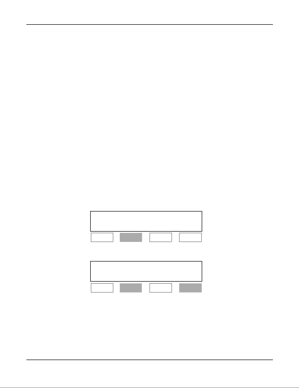
DD
(Time and Date)
Lamp A Lamp B Lamp C Lamp D
Lit
b.) When setting DO NOT DISTURB - D
Wake-UpTime
XX:XX DD
(Time and Date)
Lamp A Lamp B Lamp C Lamp D
Lit Lit
>>>
term
and AUTOMATIC WAKE-UP - D
>>>
term
:
NEAX2400 IPX Hotel Feature Programming Manual
NDA-24304, Issue 1
Page 29
Page 44

A-10D Automatic Wake-Up D
Service Conditions (cont’d)
c.) When setting DO NOT DISTURB - D
WAITING:
Wake-Up Time
XX:XX DD MW
(Time and Date)
Lamp A Lamp B Lamp C Lamp D
Lit Lit Lit
d.) When setting DO NOT DISTURB - D
WAITING and 2ND WAKEUP C ALL - SAME GUEST S TATION (MW lamp illuminates):
Wake-UpTime SecondWake-UpTime
XX:XX YY:YY MW
(Time and Date)
Lamp A Lamp B Lamp C Lamp D
Lit Lit Flashing
In case of the MESSAGE WAITING lower display (MW lamp illuminates):
term
, AUTOMATIC WAKE-UP - D
term
, AUTOMATIC W AKE-UP - D
term
>>>
>>>
term
and MESSAGE
term
, MESSAGE
XX:XX YY:YY DD
(Time and Date)
Lamp A Lamp B Lamp C Lamp D
Lit Lit Flashing
Note: On the upper LCD, AUT OMATIC WAKE-UP - D
DO NOT DISTURB - D
term
, and ROOM CUTOFF are displayed in order of priority.
e.) When setting DO NOT DISTURB - D
WAITING, 2ND W AKEUP CALL - SAME GUEST STATION and ROOM CUTOFF (the MW
lamp illuminates):
Wake-UpTimeSecondWake-UpTime
XX:XX YY:YY MW
(Time and Date)
Lamp A Lamp B Lamp C Lamp D
Lit Lit Flashing
f.) When going on-hook at the status of “e” after AUTOMATIC WAK E-UP - D
MW lamp illuminates):
Second Wake-Up Time
YY:YY DD RC MW
(Time and Date)
>>>
term
, 2ND WAKE-UP CALL - SAME GUEST STATION,
term
, AUTOMATIC W AKE-UP - D
term
, MESSAGE
>>>
Lit
term
is activated (the
>>>
Lamp A Lamp B Lamp C Lamp D
Lit Lit Lit
Page 30 NDA-24304, Issue 1
Lit
NEAX2400IPX HotelFeatureProgramming Manual
Page 45

Automatic Wake-Up D
term
Service Conditions (cont’d)
g.) When cancelling 2ND WAKEUP CALL - SAME GUEST STATION at the status “e” (the MW
lamp illuminates):
Wake-Up Time
XX:XX DD RC MW
(Time and Date)
>>>
Lamp A Lamp B Lamp C Lamp D
Lit Lit Lit
Lit
25. Maximum number of stations per LP that can be set for a single AUTOMATIC WAKE-UP time is
determined by the system data.
Assignment Procedure
STEP CMND BIT EXPLANATION
Don’t Disturb Override key on Console
b
0
0/1 = Out/In Service
Message Waiting Service
b
1
0/1 = Out/In Service
Language Service
b
2
0/1 = Out/In Service
SYS1
1
ASYD
INDEX
161
Screening Service
b
3
0/1 = Out/In Service
b
Not used
4
DSS (Direct Station Section) Key on Console
b
5
0/1 = Ineffective/Effective
Timing Start using “#” Code
b
6
0/1 = Ineffective/Effective
Timing Start using “*” Code
b
7
0/1 = Ineffective/Effective
A-10D
NEAX2400 IPX Hotel Feature Programming Manual
NDA-24304, Issue 1
Page 31
Page 46

A-10D Automatic Wake-Up D
term
STEP CMND BIT EXPLANATION
b
Destination of connection when a connection between Gueststations is restricted.
0
b1b
0
b
0 0 = ROT 1 0 = Announcement
1
b1b
0
01=ATT 11=–
b
Destination of connection when Room Cutoffis assigned.
2
b3b
2
b
SYS1
2
ASYD
INDEX
b
162
b
0 0 = ROT 1 0 = Announcement
3
01=ATT 11=–
Destination of connection when Do Not Disturb is assigned.
4
b5b
4
0 0 = ROT 1 0 = Announcement
5
b3b
b5b
2
4
01=ATT 11=–
b
Assignment of Answering Tone to Au tomatic Wake-Up Call
6
Tone to be given when a wake-up call is answered
b7 b6 b7 b6
b
7
00=MusiconHold 1 0= –
01=Announcement 1 1= –
b
Overtime Call timer.
0
b1b
0
b
b
SYS1
3
ASYD
INDEX
163
b
b
b
b
b
0 0 = 3 0 min. 1 0 = 90 min.
1
0 1 = 60 min. 1 1 = 120 min.
Overtime Call
2
0/1 = Out/In Service
Overtime Call indication
3
0/1 = On Console/Hotel Printer
Step Call from Guest Station is allowed
4
0/1 = Out/In Service
Tone type for Maid Dialing
5
b6b
5
00=SST 10=MusiconHold
6
0 1 = Announcement 1 1 = Music on Hold
Starttime of Automatic Wake-Up Call
7
0/1: On time/5min. before
b1b
b6b
0
5
Page 32 NDA-24304, Issue 1
NEAX2400IPX HotelFeatureProgramming Manual
Page 47

Automatic Wake-Up D
term
STEP CMND BIT EXPLANATION
b
Number of Digits of all Hotel ID Code
0
b2b1b
b
1
000=Notused 100=4digits
0
b2b1b
0
0 0 1 =1digit 1 0 1=5digits
b
010=2digits 110=6digits
2
011=3digits 111=Notused
ID Code for setting/cancelling Maid Status
0/1 = Not Required/Required
b
3
Note:
SYS1
4
ASYD
INDEX
164
b
Number of Digits of Group Code (PMS option)
4
5
b6b5b
b
If the dataof Bit 3 or Bit 7 is 1, Bits 0, 1, 2 of INDEX 164 must be enabled
for the number of digits.
4
b6b5b
4
0 0 0 = Not used 1 0 0 = 4 digits
0 0 1 = 1 digit 1 0 1 = 5 digits
b
6
0 1 0 = 2 digits 1 1 0 = 6 digits
0 1 1=3digits 1 1 1= Notused
ID Code to be entered when setting or cancelling Automatic Wake-Up Call from a
Special Administration Station
0/1 = Not Required/Required
b
7
Note:
If the dataof Bit 3 or Bit 7 is 1, Bits 0, 1, 2 of INDEX 164 must be enabled
for the number of digits.
b
Port Number of connectingthe HotelPrinter Command Service
0
b
b2b1b
1
000=Port0 011 =Port3
0
001=Port1 110 =Port4
b
SYS1
5
ASYD
INDEX
165
b
b
b
b
b
010=Port2 101 =Port5
2
Hotel Printer Command Service
3
0/1 = Not Required/Required
Automatic Wake-Up - Hotel Attendant Assistant
4
0/1 = Out/In Service
Wake-Up Guest Station Priority Service
5
0/1 = Not Provided/Provided
Wake-Up information (time, station number, etc.) printout
6
0/1 = Out/In Service
Floor Service
7
0/1 = Out/In Service
b2b1b
0
110 =Port6
111 =Port7
A-10D
NEAX2400 IPX Hotel Feature Programming Manual
NDA-24304, Issue 1
Page 33
Page 48

A-10D Automatic Wake-Up D
term
STEP CMND BIT EXPLANATION
b
0
Miscellaneous Timer Counter (MTC) is to be assigned 0 a value from 0 Hex, (0-15)
b
1
Announcement trunk release timer to reset the announcement. Available only with single
b
SYS1
6
ASYD
INDEX
169
SYS1
ASYD
7
INDEX
171
AHSY
8
INDEX
77
2
connection. 2 sec. MTC (If MTC = 0 Hex: 30 sec.)
b
3
b
4
b
5
Assign data specifying how many minutes earlier the wake-up time for the
overflowed stations (more than 500/LP). 5 min x N Hex.
b
6
b
7
b
0
b
1
b
2
This datadesignates how many times retry is allowed when Room Data image transfer
b
3
fails (Usually, 10 Hex.)
b
4
b
5
b
6
b
Fixed “0”
7
LCD Indication of Wake-Up time on the D
b
0
0/1 = -/Remains lit
LCD Indication of “DD” (Do Not Disturb) on the D
b
1
0/1 = -/Remains lit
LCD Indication of “ RC” (Room Cutoff) on the D
b
2
0/1 = -/Remains lit
LCD Indication of 2nd Wake-Up time on the D
b
3
0/1 = -/Remains lit
b
4
b
5
Not used
b
6
b
7
term
term
term
term
Page 34 NDA-24304, Issue 1
NEAX2400IPX HotelFeatureProgramming Manual
Page 49

Automatic Wake-Up D
term
STEP CMND BIT EXPLANATION
b
Number of times of Wake-Up Answer Retry
0
b1b
0
00=NoAnswerRetry0time
b
01=NoAnswerRetry1time
1
1 0 = No Answer Retry 2 times
1 1 = No Answer Retry 3 times
Number of characters of la nguage information display
b
2
0/1 = 4 characters/2 characters
Restrictionfor hooking whe n a Guest station has originated an outgoing C.O. line call.
b
3
0/1 = Not Required/Required
AHSY
9
INDEX
100
Note
Type of S TA for Overtime Call
<Overtime Call Indication on Console (SI 163 b
b
4
=0)>
3
00:- 10: Administration STA only
01: Guest STA only 11: Both (Administration and Guest STA)
<Overtime Ca ll Indication on Hotel Printer (SI 163 b
b
5
00: Both (Adm. and Gst. STA)10: Adm. STA only
01: Gst. STA only 11: Both (Adm. and Gst. STA)
Overtime Call when a station user places a C.O. trunk call
b
0 = Administration and Guest go to Console
6
1 = Guest only goes to Console
Key that means the P.M. in a case where Wake-Up time is set by the 12-hour system
b
(for Automatic Wake-Up Service).
7
*Key/#Key
0/1 =
Note:
This entry will be the number of times the Wake-Up Call is attempted before AHSY, INDEX 142 takes
effect.
b
0
Not used
b
1
Maid Dial service from Console
b
2
0/1 = Not Required/Required
b
Not used
3
Wake-Up Time Indication on Hotel Console
b
4
0/1 = 24-hour/12-hour system
b
5
Not used
b
6
Guest Name Display on Console
b
7
0/1 = Interface Type Model 60, 90, 120/Model 90, 120
10
AHSY
INDEX
105
=1)>
3
A-10D
NEAX2400 IPX Hotel Feature Programming Manual
NDA-24304, Issue 1
Page 35
Page 50
A-10D Automatic Wake-Up D
term
STEP CMND BIT EXPLANATION
b
0
b
1
Not used
b
2
b
3
Wake-Up call “Busy” c ondition; transfer to Console.
b
4
0/1 = Out/In Service
Wake-Up call“Don’t Answer”condition;transfer to Console.
b
5
0/1 = Out/In Service
Wake-Up call “Block” condition; transfer to Console.
b
6
0/1 = Out/In Service
Wake-Up call for VIP Busy/Block condition; transfer to Console.
b
7
0/1 = Out/In Service
2nd Wake-Up Call Service
b
0
0/1 = Out/In Service
2nd Wake-Up Call Time Indication on Console
b
1
0/1 = Out/In Service
2nd Wake-Up Call Cancel while Console is connectedto the target station
b
2
0/1 = Out/In Service
b
Not used
3
ThenumberofcallsforwhichAutomaticWake-Upisatthesametime(perLP)
b
4
b
5b4
b
0 0 = 512 calls 1 0 = 128 calls
5
01=64calls 11=256calls
b5b
4
The numberof Retries when a Wake-Up Call encountersbusy status.
b
7b6
b7b
6
00=3Times 10=Once
11
12
AHSY
INDEX
142
AHSY
INDEX
163
b6
b7
0 1 = Twice 1 1 = No Retry
Daily P rintout Hour
“Hour” data is assigned using a decimal number (Military Time).
Example: 2:00 a.m. - This data is entered as 02.
Example: 2:30 p.m. - This data is entered as 14.
Daily Printout Minute
“Minute” data is assigned using a decimal num ber (Mi l itary Time).
Example: 2:00 a.m. - This data is entered as 00.
Example: 2:30 p.m. - This data is entered as 30.
13
14
AHSY
INDEX
400
AHSY
INDEX
401
Page 36 NDA-24304, Issue 1
NEAX2400IPX HotelFeatureProgramming Manual
Page 51

Automatic Wake-Up D
term
STEP CMND BIT EXPLANATION
15
AHSY
INDEX
402
b
0
Wake-Up Result (Answer) Printout
b
1
0/1 = Out/In Service
b
2
b
3
b
4
Not used
b
5
b
6
b
7
Not used
STEP CMND EXPLANATION
16
AANP
or
AGNP
Assign the Number of Necessary Digits for the first numeral of the Automatic Wake-Up Service
Access Code.
Assign the Automatic Wake-Up Service Access Code.
When setting and cancelling are made by each individual Access Code.
• For Setting: CI = N, SRV = 2(SSC), SID = 48
• For Cancelling: CI = N, SRV = 2(SSC), SID = 49
When setting and cancelling are made by the same one Access Code (for a 12-hour system):
CI = N, SRV = 2(SSC), SID = 36, STATE = 33
Assign the 2 nd Wake-Up service access if required.
17
AASP
or
AGSP
• For Setting: CI = N, SRV = 2(SSC), SID = 36, STATE = 48
• For Cancelling: CI = N, SRV = 2(SSC), SID = 36, STATE = 50
18 AKYD
19 ASFC
Note:
Steps after ARTD are ne cessary only when the destination of the tone of Automatic Wak e-Up call is
Note:
If necessary, assign the following key data on the D
Type:Function:WAKE UP SET (WUS) [87]
Allow SFI = 41 for the SFC of the stations that re ceive Automatic Wake-Up service.
(for SFI = 41, RES = 1).
2nd Wake-Up service can be set and/or cancelled from a C onsole only.
term
line/feature key:
designated as Announcement Machine (See ASYD, INDEX162).
20 ARTD
21 ATRK Assign the trunk interfacing with the announcement unit.
22 MBTK Release the Make Busy of the trunk assigned i n ATRK.
23 ARSC
24 AAED
Assign route data of the trunk which interfaces with the announcement unit.
(OSGS = 2, TCL = 4)
Release the Call restrictions between the RSC of the station accessing the announcement unit and
the route of the trunk assigned in ATRK.
(RRI = 2.3)
Assign the Data to the announcement unit number and the route data, etc. assigned in ATRK.
Assign the information with respect to the following:
EQP = 16: Automatic Wake-Up Set
EQP = 18: Automatic Wake-Up Cancel
EQP = 22: Automatic Wake-Up Answer
A-10D
NEAX2400 IPX Hotel Feature Programming Manual
NDA-24304, Issue 1
Page 37
Page 52

A-15 Announcement Service
A-15 Announcement Service
General Description
This service feature allows a station user to hear a prerecorded announcement for various services such as:
ALERT SERVICE [A-57]
AUTOMATIC WAKE-UP [A-10]
Confirmation announcement (See AUTOMATIC WAKE-UP) [A-10]
DO NOT DISTURB [D-11] mode setting
GROUP SERVICE THROUGH P MS [G-4]
Hotel information
Intercept announcement when a vacant level is dialed
Language selection (Property Management System ( PMS) option)
Restricted call attempts(ROOM CUTOFF) [R-9]
Tourist group information (tour group schedule & agenda)
Operating Procedure
To access
1. Lift the handset or press the SPEAKER key. Receive dial tone.
2. Dial the associated announcement service access code. The N EAX2400 IPX responds with an
announcement.
3. Listen to the announcement and hang up.
Service Conditions
1. This feature requires one of the following hardware alternatives:
a.) Central Office Trunk (COT) or 2W E& M trunk and an announcement machine.
b.) Digital Announcement Trunk (DAT).
2. Announcements can be arranged as continuous recordings (last-party disconnect) or to automatically
disconnect after 30 seconds. An engineering traffic study is required to determine the number of interface
trunks needed to accommodate each recording channel.
3. If PMS Language Selection is utilized, ANNOUNCEMENT SERVICE can be provided according to
Guest’s language.
4. The following connections are available:
a.) Multi-connection - many station users can connect to one announcement trunk at the same time.
b.) Single connection - one station user can connect to one announcement trunk at the same time
5. This feature is also available for the Tie Line trunk access to announcement trunk.
6. The NEAX2400 IPX can be programmed to return Ring B ack Tone before connection to the
announcement machine is made.
7. When this feature is activated from a Tie Line, the NEAX2400 IPX can be programmed to return answer
supervision to far-end PBX.
8. If PMS Language Selection is used, Announcement Service can be provided according to the Guest’s
language.
9. Checked out Guest Stations cannot use this feature, except for Room Cutoff Announcement.
Page 38 NDA-24304, Issue 1
NEAX2400IPX HotelFeatureProgramming Manual
Page 53

Announcement Service A-15
Assignment Procedure
STEP CMND PR OCEDURE
AANP
1
2
or
AGNP
AASP
or
AGSP
Assign minimum necessary number of digits for the first number of the Announcement Service
Access Code
Assign the access code to the announcement unit number.
CI = N&H, S RV = ANNC, EQP =
EQP: Announcement unit number
3ARTD
4 ARTD Assign the t runk interfacing with the announcement unit.
5 MBTK Release the Make Busy of the trunk assigned in ATRK.
6ARSC
Assign the route data of the trunk which interfaces with the announcement unit.
(LSG=5,TCL=4)
Release the Call restrictionsbetween the RSC of the station accessing the announcement unit and
the route of the trunk assigned in ATRK.
(at RRI = 2, 3)
Assign the Data to the announcement unit number and the route data, etc., a ssigned in AT RK.
EQP =
,LANG= Note 1 , C= , R = , A =
(0/1 = Out/In Service)
Note 2
station. (= 0/1)
7AAED
Note 1:
M=
C = connection time: disconnected in 30 seconds/connected until caller releases the
R = RBT transmission: RBT transmission/No RBT transmission. (= 0/1)
A= 0=NoanswersupervisiontoINCTRK
1= AnswersupervisiontoINCTRK
M =Multiple Connection: single connection/multiple connection. (= 0/1)
,RT= ,TK=
This parameter appears when Language service is provided by ASY D1, INDEX
161, Bit 2.
Note 2: This parameter appears when M is 1.
NEAX2400 IPX Hotel Feature Programming Manual
NDA-24304, Issue 1
Page 39
Page 54

A-25 Attendant Console With Hotel Functions
A-25 Attendant Console With Hotel Functions
General Description
The NEAX2400 IPX Console provides r egular business call handling and processing capabilities, as well as
hospitality features. The console provides for the following special hospitality services:
1. Individual keys to set and reset:
AUTOMATIC WAKE-UP [A-10]
MESSAGE WAITING [M-6]
CHECK-IN/CHECKOUT [C-23]
DO NOT DISTURB [D-11]
SECRETARIALSERVICE - GUEST STATION [S-74]
ROOM STATUS [R-10]
MANUAL SWITCHING OF C.O. IN COMING CALL DESTINATION[M-51]
ROOM CUTOFF [R-9]
AUDIT REPORT [A-26] (requires hotel printer)
2. Special keys for incoming call identification:
ADM - Incoming administrative calls
DD - Incoming calls to stations in DO NOT DISTURB [D-11] mode
EMG - OFF HOOK ALARM [O-6] - Emergency calls (option)
GST - Incoming Guest station calls
GST2 - Incoming foreign Guest station calls (option)
HP - HOUSE PHONE/HOT LIN E [H-8]
OT - Overtime calls (option)
WU - Wake-Up calls (option) (Morning Call [MC])
3. Direct key access to frequently called Administration or service stations (i.e., room service, restaurant,
maid, or C.O . number). These numbers are preassigned via the MAT. Ten keys a re provided for this
feature.
4. The console provides the following displays:
Calendar (date and time)
Call Waiting (number of calls)
Class of Service
Name Display - System (for Administration stations)
Room Status:
- AUTOMATIC WAKE-UP [A-10]
- DO NOT DISTURB [D-11]
- GUEST NAME DISPLAY THR OUGH PMS [G-5]
- Language (PMS Option)
- MESSAGE WAITING [M-6]
- Optional data display (Refer to Service Condition 3.)
- Room class
- ROOM CUTOFF [R-9]
- Room occupied
- Station number
- VIP (PMS option)
Station/Trunk
Tenant Number
Page 40 NDA-24304, Issue 1
NEAX2400IPX HotelFeatureProgramming Manual
Page 55
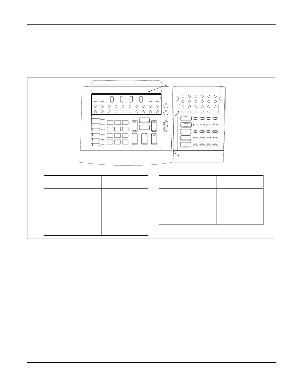
Attendant Console With Hotel Functions A-25
General Description (cont’d)
Note: If the Desk Console isused insteadof theN EAX2400 IPX Hotel AttendantConsole, the basic key allocations
are different from the previous ones. The following illustration shows the Desk Console key positions and
indications used in Hotel Systems. The operating procedures for each service are the same as the
NEAX2400 IPX Hotel Attendant Console.
LCD
TRKSL SVC SC
HWS BV
Alarm Position Available
HWC HP DD GST OT ICPT
L 6
L 5
L 4
L 3
L 2
L 1
1
2
ABC3DEF
6
5
MNO
JKL4GHI
9
8
7
WXYZ
TUV
PQRS
0
∗
#
TFRecallNANSADMBusyTIELDN
SRC
Release Hold
Cancel
Talk
Position Busy
PAGE REC
Start Mute
DEST
Answer
Night
Night
Position Busy
DDO
WUS
DDS RCS MWS
WUR DDR RCR MWR STS
MR CLR
Enter
Clear
Exit
Hotel Function key
TG6
TG1
TG2
TG7
TG3
TG8
TG9
TG4
TG10TG5
DSS key
The different key indications of the NEAX2400 IPX Attendant Console and the Desk Console are shown below:
HOTEL ATTENDANT
CONSOLE DES K CONSOLE
WKUP ( S et)
WKUP (Reset)
DD (Set)
DD (Reset)
RC ( S et)
RC (Reset)
MW (Set)
MW (Reset)
WUS
WUR
DDS
DDR
RCS
RCR
MWS
MWR
HOTEL ATTENDANT
CONSOLE DESK CONSOLE
TKSL
TRKSL
SRLC
DD OVER
PG
RCL
OT
SC
DDO
PAGE
Recall
OT
Figure 1 Key Allocations of Desk Console
Operating Procedure
Refer to the NEAX2400 IPX How to Operate Attendant Console.
Service Conditions
1. Distance limitation between the NEAX2400 IPX and the console: up to 1000 feet (304 meters) using 25pair, 24 AWG cable.
2. Maximum of four consoles per PIM.
3. A three-character and a five-character display can be used in conjunction with PMS to display additional
Guest information instead of language and room class. F or example, company name, complementary
code, etc. may be displayed.
4. The OAI name of the Administration station is displayed on the c haracter display (Guest name display
area) when Name Display service via OAI is available in the NEAX2400 IPX. When there is no name
assigned for the Administration station, “ADM S TATION” is displayed.
NEAX2400 IPX Hotel Feature Programming Manual
NDA-24304, Issue 1
Page 41
Page 56
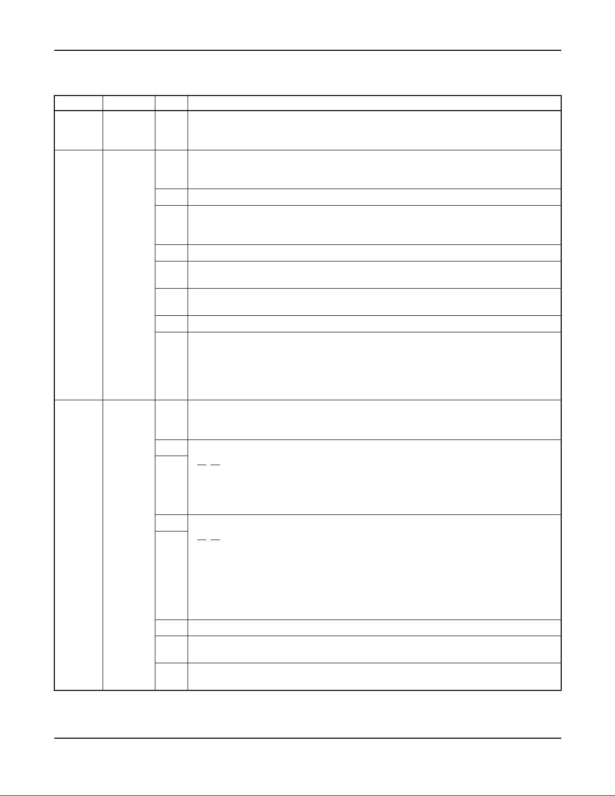
A-25 Attendant Console With Hotel Functions
Assignment Procedure
STEP CMND BIT EXPLANATION
SYS1
1
ASYD
INDEX 9
SYS1
2
ASYD
INDEX 43
SYS1
3
ASYD
INDEX 64
Number of Consoles
Maximum 4 c onsoles per PIM.
For Remote Access to System, is Forced Account (F/A) Code Dialing required upon
b
receiving ringback tone?
0
0/1 = Required/Not Required
b
Not used
1
Send service set tone after ACC Code dialing for Authorization Code or F/A code is dialed
b
using LCR Access
2
0/1 = Out /In Service
b
Not used
3
Console Re-enters Loop on Serial Call
b
4
0/1 = Restriction/Allowed
Send dial tone to the distantOffice upon receiving Terminated Office Code (Tandem)
b
5
0/1 = Not Required/Required
b
Not used
6
Restriction for Dialing more than the maximum of necessary digits (as assigned via
command “AMND”)
0/1 = Not Required/Required
b
7
Note:
If a calling partydials morethan the maximumnecessary digits, the c alling
party receives a reorder tone.
µ law/A law for TDSW
0 = µ law (Japan, North America, Canada, and Hong Kong)
b
0
1 = A law (Europe, other nations)
b
Display o f C all Waiting Lam p (on Console) service
1
b1b
2
0 0 = WhenPAlampilluminates
0 1 = When busy lamp field is not displayed
b
2
1 0 = Always
11=-
b
Howler Tone Se nding Service
3
b4b
3
00=OutofService
0 1 = Send one time only
1 0 = Repeat every 30 sec.
b
4
11=-
Note:
The Sending T imer may be changed to a value other than 30 sec. via SYS1,
INDEX 146.
b
Not used
5
Type of Attendant Camp-On
b
6
0/1 = Semi-Auto/Automatic (Normally Assign “0”)
Music On Hold service
b
7
0/1 = Out /In Service
Page 42 NDA-24304, Issue 1
NEAX2400IPX HotelFeatureProgramming Manual
Page 57

Attendant Console With Hotel Functions A-25
STEP CMND BIT EXPLANATION
Operating method for busy station service (Call Back, Executive Right-of-Way, e tc.)
b
0
0/1 = SHF + Access Code/Last Digit + Access C ode
Operating method for Individua l Trunk Access (Console) service
b
0 = Route No. + Trunk No.
1
1 = C.O. Code (as assigned via command “ACOC”)
Ringing Signal type for TAS indicator
b
2
0/1 = Interval/Continuous
OG Trunk Queuing (On-Hook) Automatic Cancel
b
3
0/1 = Out /In Service
SYS1
4
ASYD
INDEX 68
TKSL key on the Console (for Individual Trunk Access service)
b
4
0/1 = Not used/used
b
Not used
5
Ground Button (GB) used for SHF
b
6
0/1 = Not Required/Required
OG call operation
-
B
b
7
Day/Night mode change via the Console handset jack
b
0
0/1 = Not Required/Required
b
Not used
1
7
0 Off-Hook Off-Hook with pressing GB
1 Off-Hook with pressing GB Off-Hook
VIA
CONSOLE
DIRECT DIAL
ACCESS
MW Refresh 0/1 = Required/Not Required
b
Note:
SYS1
5
ASYD
INDEX 77
SYS1
6
ASYD
INDEX
160
2
b
Service Module Interface 0/1 = Required/Not Required
3
b
4
Module in that PFT card is mounted
PIM (Always assign “11”.)
b
5
b
6
Not used
b
7
b
Hotel Feature required (Fixed Da ta)
0
b
Hotel Service kind (Fixed Data)
1
Length of Room Status Memory
b
2
0/1 = 8 byte/24 byte
b
3
Pattern of Key Arrangement on Console
(Refer to Figure 4) (Usually, 00)
b
4
b
Guest Name Service 0/1 = Out/In Service
5
Numbering Plan Data Table of Guest and Administration stations Note 1
b
6
0/1 = Separate/Common
b
Fixed “0”
7
When message Waiting Lamp is provided, this data should be assigned
“0”.
NEAX2400 IPX Hotel Feature Programming Manual
NDA-24304, Issue 1
Page 43
Page 58

A-25 Attendant Console With Hotel Functions
STEP CMND BIT EXPLANATION
Don’t Disturb Override key on Console
b
0
0/1 = O ut/In Service
Message Waiting Service
b
1
0/1 = O ut/In Service
Language Service
b2
0/1 = O ut/In Service
7
Note 1:
SYS1
ASYD
INDEX
161
If the data is assigned as 1, only use commands AANP & AASP to assign Administration and Guest
Screening Service
b
3
0/1 = O ut/In Service
b
Not used
4
DSS (Direct Station Section) Key on Console
b
5
0/1 = Ineffective/Effective
Timing Start using “#” Code Note 2
b
6
0/1 = Ineffective/Effective
Timing Start using “*” Code Note 2
b
7
0/1 = Ineffective/Effective
numbering plans. If Data 0 is assigned, use AANP & AASP for Administration N umbering Plan, and
AGNP & AGSP for Guest N umbering Plan.
Note 2: Do not assign “*” or “#” as last digit of Feature Ac cess Code. No station may use “*” or “#” in
Numbering Plan.
DLKC CircuitCard for Console
b
0
0/1 = N ot exist in system/Exist in system (for NEAX2400 IPX, 4 IMG system only)
b
1
SYS1
8
ASYD
INDEX
257
b
b
b
b
b
b
2
3
4
5
6
7
Not used
Page 44 NDA-24304, Issue 1
NEAX2400IPX HotelFeatureProgramming Manual
Page 59
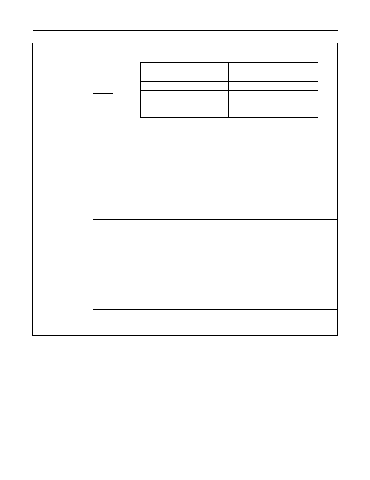
Attendant Console With Hotel Functions A-25
STEP CMND BIT EXPLANATION
Restriction Data of Station Busy Services can be designated as the table below:
10
b
0
B
1
CALL
B
BACK
0
EXECUTIVE
RIGHT-OF-
WAY
00RR RRR
01 A R A A A
10 R A A A A
b
SYS2
9
ASYD
INDEX
0
1
b
Not used
2
Attendant Override service
b
3
0/1 = Out/In Service
Busy Verification (Console) service
b
4
0/1 = Out/In Service
b
5
b
Not used
6
b
7
Sender Signal to DP/PB Route (Station)
b
0
0/1 = DP/PB
Sender Signal to DP/PB Route (Console)
b
1
0/1 = D P/PB
11 A A A A A
R: Restricted A: Allowed
Console Day/Night Mode Change
b2
b3b
2
SYS2
ASYD
INDEX
2
0 0 = Not Required (External Switch effective)
0 1 = Primary Console
b
1 0 = All Consoles
3
11=–
b
Not used
4
Attendant Loop Release service
b
5
0/1 = O ut/In Service
b
Not used
6
Kind of DP sender (when b0 = 0)
b
7
0/1 = 10 PPS/20 PPS
CALL
WAITING-
ORIGINATING
VOICE
CALL
TERM
(D
)
MESSAGE
REMINDER
TERM
(D
)
NEAX2400 IPX Hotel Feature Programming Manual
NDA-24304, Issue 1
Page 45
Page 60

A-25 Attendant Console With Hotel Functions
STEP CMND BIT EXPLANATION
Message C enter Interface service when terminating to a UCD Group
b
0
0/1 = Out /In Service
b
1
b
Not used
2
b
3
Call Origination Restriction of Station upon Setting Call Forwarding-All Calls
b
4
0/1 = Required/Not Required
Inter-Position Transfer service
b
5
0/1 = Out/In Service
b
Not used
6
CallForwarding - Don’t Answer service (at Console)
b
7
0/1 = O ut Service (Recall to Console)/In Service
Busy Lamp Field
b
0
0/1 = O ut/In Service
Message C enter Interface service when terminating Console
b
1
0/1 = Out /In Service
Serial Call service
b
2
0/1 = O ut/In Service
Supervisory Call service
b
3
0/1 = O ut/In Service
b
4
b
5
First Digit of Phantom Station Number for Privacy Expansion
b
6
b
7
Call Waiting Display on Console
CW Lamp on Console-Threshold
b
CW Lamp flashes when the number of Calls Waiting is greater than or equal to this
0
data.
b3b2b1b
b
1
0 0 0 0 = No Flash 1 0 0 0 = 8 Calls
0
b3b2b1b
0
0 0 0 1 = 1 Call 1 0 0 1 = 9 Calls
0 0 1 0 = 2 Calls 1 0 1 0 = 10 Calls
0 0 1 1 = 3 Calls 1 0 1 1 = 11 Calls
b
2
0 1 0 0 = 4 Calls 1 1 0 0 = 12 Calls
0 1 0 1 = 5 Calls 1 1 0 1 = 13 Calls
0 1 1 0 = 6 Calls 1 1 1 0 = 14 Calls
b
3
0111=7Calls 1111=15Calls
Calls that activate CW Lamp Flash
b
4
0/1 = All Calls/Only the types of Calls specified i n SYS2, INDEXes 8 and 9
b
5
b
Not used
6
b
7
11
12
13
14
SYS2
ASYD
INDEX
6
SYS2
ASYD
INDEX
7
SYS2
ASYD
INDEXES
8&9
SYS2
ASYD
INDEX 14
Page 46 NDA-24304, Issue 1
NEAX2400IPX HotelFeatureProgramming Manual
Page 61

Attendant Console With Hotel Functions A-25
STEP CMND BIT EXPLANATION
b
0
Not used
b
1
Maid Dial service from Console
b
2
0/1 = Not Required/Required
b
AHSY
15
INDEX
105
AHSY
16
INDEXES
101 & 102
AHSY
17
INDEX
109
AHSY
18
INDEX
183
STEP CMND EXPLANATION
19
20
AANP
or
AGNP
AASP
or
AGSP
Assign 1st digit for C onsole Access Code.
(CI = N&H, NND = , BLF = 0)
Assign Console Access Code.
(CI = N&H, SRV = 2(SSC), SID = 2)
21 ATNR Release the connection restriction between the tenants.
22 ATRK
Assign the LENS data for the Console.
(RT = 901, RSC = 0, SFC = 0)
23 MBTK Release the trunk for console make busy.
Not used
3
Wake-Up Time Indication on Hotel Console
b
4
0/1 = 24-hour/l2-hour system
b
5
Not used
b
6
Guest Nam e Display on Console
b
7
0/1 = I nterface Type Model 60, 90,120/Model 90, 120
When an incoming call terminates tothe Hotel/Motel Console from aGuest station of
the language category correspondingto each bit. The key to which the call
terminates:
0: GST1 Key
1: GST2 Key
Language data is assigned on each Guest station as per the information from the
PMS.
Busy Status Display - Console
0/1 = Out /In Service
b
5
Note:
b
0
Setting of Hotel/Motel Console that sets Alert Service
b
1
0 Hex: Service can be set from any of the Console
b
2
1-F Hex: Service can be set only from the Console of the designated Console Number
b
3
Other bits are not to be assigned for service.
Classifyingthe call termination indicatingkeys on the basis of the Language category
of the Guest at the time an incoming call from a Guest stationhas terminated to the
b
4
Hotel/Motel Console.
0/1 = Not Required/Required
b
Not used
5
In the c ase of “All Event No Printout”, the Hotel printer prints out only the information
b
pertaining to outgoing c alls.
6
0/1 = Out/In Service (The outgoing call data is assigned by INDEXes 360 through 367.)
b
Not used
7
NEAX2400 IPX Hotel Feature Programming Manual
NDA-24304, Issue 1
Page 47
Page 62

A-25 Attendant Console With Hotel Functions
STEP CMND EXPLANATION
24 ARSC Release the route restriction (RSC = 0) for the Console.
Function 6 = GST2 (Foreign Guest)
25 AAKP
Function 7 = ATT-Assist Wake-Up
Function 8 = Interposition Transfer
Table 7 Key Arrangement for Hotel Attendant Console
DATA
B
B
4
3
00
01
10
11
WUS
WUR
WUS
WUR
WUS
WUR
WUS
WUR
KEY ARRANGEMENT REMARKS
DDS
MWS
RCS
AUD
WUS: Wake Up Set
WUR: Wake Up Reset
DDR
MWR
RCR
STS
DDS: Do Not Disturb Set
DDR: Do Not Disturb Reset
DDS
MWS
RCS
COC
MWS: Message Waiting Set
MWR: Message Waiting Reset
DDR
MWR
RCR
STS
RCS: Room Cutoff Set
RCR: Room Cutoff Reset
DDS
MWS
RCS
C/I
AUD
AUD: Audit Report
STS: Status Check
C/I: Check-In
DDR
MWR
RCR
C/O
STS
C/O: Checkout
SCS: Boss-Secretary Set
DDS
MWS
RCS
SCS
AUD
SCR: Boss-Secretary Reset
COC: Manual Switching of C.O. Incoming
DDR
MWR
RCR
SCR
STS
Call
Page 48 NDA-24304, Issue 1
NEAX2400IPX HotelFeatureProgramming Manual
Page 63

Audit Reports A-26
A-26 Audit Reports
General Description
The NEAX2400 IPX provides AUDIT REPORT printout of all rooms assigned specific R oom Status conditions.
For example, an AUDIT of all stations in DO NOT DISTURB [D-11] mode m ay be ordered. These REPORTS are
generated by key operation and function codes entered from the Hotel Console. AUDIT REPORTS available from
the printer are as follows:
Table 8 Audit Report
FUNCTION
CODE DEFINITION
PRINTOUT INFORMATION
0 All Status All Status
1
To be Cleaned
2 Cleaned
3 Readytosell
Maid Status
4 Out of Service
5 Repair Needed
6 Vacant
7
Occupied
8 MESSAGE WAITING set [M-6]
9 AUTOMATIC WAKE-UP [A-10] (Room & T ime)
Room Condition
10 Vip Room (see service condition, PMS option)
11 DO NOT DISTURB [D-11]
12 ROOM CUTOFF [R-9]
*
All Class Audit
21 Room Class 1
22 Room Class 2
23 Room Class 3
24 Room Class 4
25 Room Class 5
26 Room Class 6
Room Class
27 Room Class 7
28 Room Class 8
29 Room Class 9
20 Room Class 10
2* Room Class 11
2# Room Class 12
NEAX2400 IPX Hotel Feature Programming Manual
NDA-24304, Issue 1
Page 49
Page 64
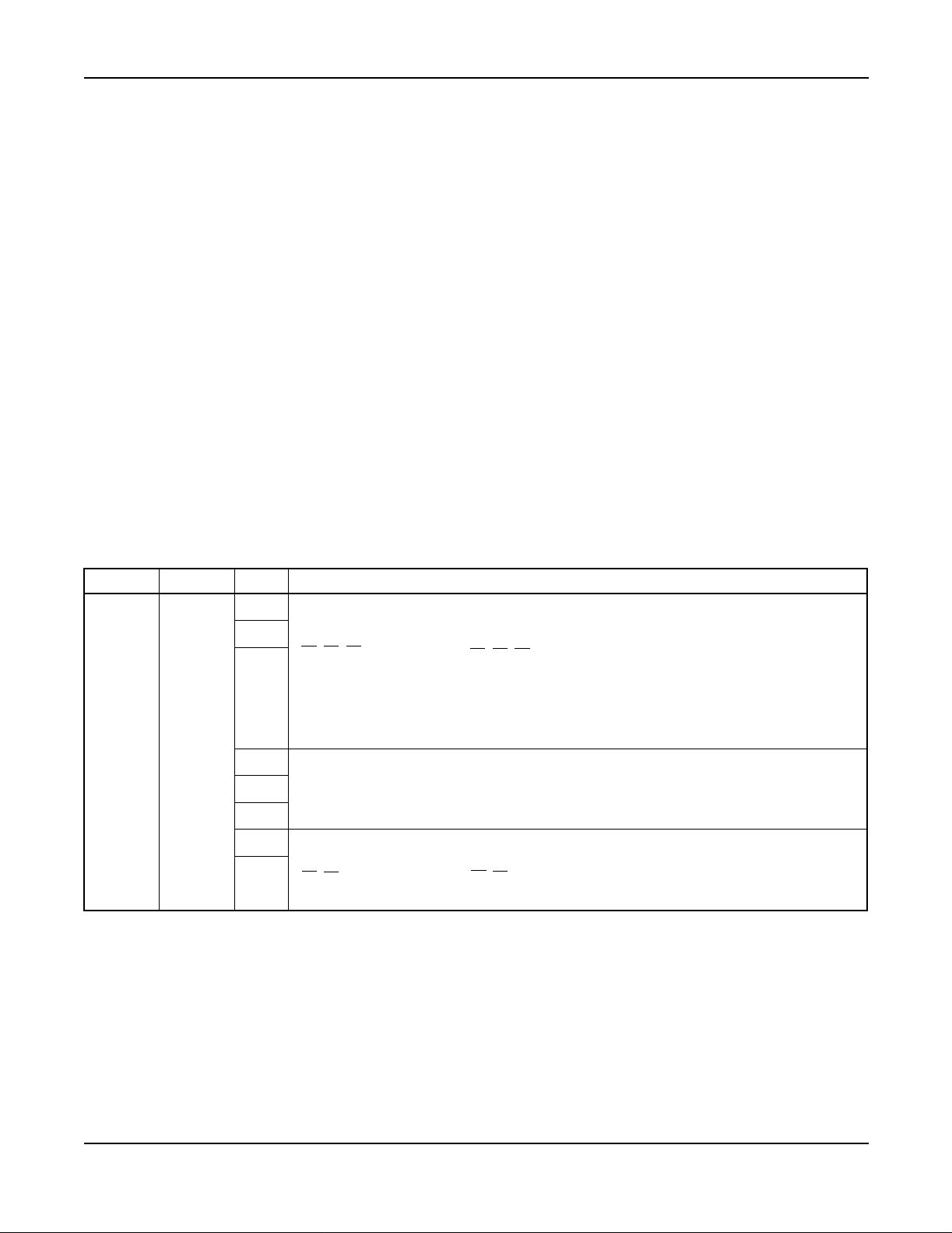
A-26 A udit Reports
Operating Procedure
To order AUDIT RE PORT S printouts from the Console or F ront D esk Terminal
1. Press the AUD key. The associated lamp illuminates
2. Press the STS key. Dial the desired function code.
3. The function c ode is displayed. Press the ENTER key.
4. All displayed information is cleared and lamps are extinguished. Printout begins.
Service Conditions
1. VIP classification must be entered via PMS.
2. Room classifications are assigned via the MAT.
3. Guest name and optional data (Language, etc.) are displayed on the C onsole, but are not included in the
printout.
4. Hotel printer is ne cessary for this service feature.
5. Only one audit may be run at a time.
6. Status information is automatically printed out when the following services are performed:
• MAID STATUS [M22] (from Guest room only).
• AUTOMATIC WAKE-UP [A-10] (unanswered, blocked calls).
Assignment Procedure
STEP CMND B IT EXPLANATION
b
I/O Port designation to Hotel Printer (Model 60/90/120 PMS)
0
b
b
SYS1
1
ASYD
INDEX
11
b
b
b
b
b
1
b2b1b
0
b2b1b
0
000=Port0 011=Port3
001=Port1 100=Port4
010=Port2 101=Port5
2
110=Port6
111=Port7
3
NotUsed
4
5
Transmission Protocol between PBX and Hotel Printer
6
b7b
6
0 0 = Out of Service 1 1 = BSC
7
b7b
6
0 1 = Level 2A 0 0 = Free Wheel
Page 50 NDA-24304, Issue 1
NEAX2400IPX HotelFeatureProgramming Manual
Page 65

Audit Reports A-26
STEP CMND B IT EXPLANATION
Group Announcement Service (for Hotel system)
b
0
0/1 = Out/In Service
b
1:AuditReportinservice
1
b
2
Notused
SYS1
2
ASYD
INDEX
168
STEP CMND EXPLANATION
3 AIOC Assign printer port to match SYS1, ASYD, INDEX 11, in Step 1 above.
4 AGST Assign Room Class
b
3
Off-Hook Alarm (Se rvice)
b
4
0/1 = Out/In Service
Destination for Off-Hook Alarm Termination
b
5
0/1 = Console/Station
Destination for Priority Call Termination
b
6
0/1 = Console/Station
b
Notused
7
NEAX2400 IPX Hotel Feature Programming Manual
NDA-24304, Issue 1
Page 51
Page 66

A-48 Automatic Message Waiting Lamp Off
A-48 Automatic Message Waiting Lamp Off
General Description
This feature provides for Guest station MESSAGE WAITING [M-6] lamps to automatically turn off after Guests
have called predetermined Adm inistration Stations (i.e. Message Center) to retrieve messages.
Operating Procedure
When a Guest calls the Administration Station to retrieve a message, the MESSAGE WAITING [M-6] lamp on the
associated Gue st telephone is automatically extinguished and the MESSAGE WAITING [ M-6] data is cleared.
Service Conditions
1. This service is only available when the MESSAGE WAITING [M-6] has been set from:
a.) Front Desk Terminal (Model 90 or 120 PMS).
b.) Front Desk Terminal or Console (Model 60 PMS).
2. This feature is not available when calling the Console.
3. Message Waiting lamps set by Message Center Interface will not be cancelled by AUTOMATIC
MESSAGE WAITING LAMP OFF [A-48].
4. Refer to MESSAGE WAITING [M-6] for more information.
Assignment Procedure
STEP CMND BIT EXPLANATION
b
b
b
SYS1
1
ASYD
INDEX
161
b
b
b
b6
b7
Don’t Disturb Override key on Console
0
0/1=Out/InService
Message Waiting Lamp in Service
1
0/1 = Out/In Service
Language Service
2
0/1=Out/InService
Screening Service
3
0/1=Out/InService
Not used
4
DSS (Direct Station Section) Key on Console
5
0/1 = Ineffective/Effective
Timing Start using “#” Code
0/1 = Ineffective/Effective
Timing Start using “*” Code
0/1 = Ineffective/Effective
Page 52 NDA-24304, Issue 1
NEAX2400IPX HotelFeatureProgramming Manual
Page 67
Automatic Message Waiting Lamp Off A-48
STEP CMND BIT EXPLANATION
b
Message Waiting
0
Message Registration
b1
b
Do Not Disturb, Room Cutoff
SYS1
2
ASYD
INDEX
172
2
b
Room Status
3
b
Automatic Wake-Up, Group Announcement
4
b
Room Change, Room Swap
5
b
Room Data Change
6
b
Not used
7
b
Ringing D uration for Automatic Wake-Up
0
b
1b0
00 =30sec. 1 0 = 45sec.
b1
b1b
0
01 =15sec. 1 1 = 60sec.
SYS1
3
ASYD
INDEX
179
Automatic Message Waiting Lamp Off
b
2
0/1 = Out/In Service
b
Not used
3
b
ATT Monitor Service 0/1 = Out/In Service
4
b
5
b
Not used
6
b
7
b
0
Not used
b1
MW Lamp Indication of “Do Not Disturb”
b
2
0/1 = L ights Steadily/Flashes
MW Lamp Indication of “Do Not Disturb”
b
3
AHSY
4
INDEX
139
STEP CMND EXPLANATION
5ASFC
Release the restriction of SFI = 69 for the SFC of the stations that receives Automatic Message
Waiting Lamp-Off service.
0/1 = Not Required/Required
MW Lamp Indication of “Message Waiting”
b
4
0/1 = L ights Steadily/Flashes
MW Lamp Indication of “Message Waiting”
b
5
0/1 = Not Required/Required
2-Line Guest Name Display on a D
b
6
0/1 = Out/In Service
b
Not used
7
term
Data transfer to/from PMS
when executing the service.
0/1 = Not to be executed/ To
be executed.
NEAX2400 IPX Hotel Feature Programming Manual
NDA-24304, Issue 1
Page 53
Page 68

A-57 Alert Service
A-57 Alert Service
General Description
In an emergency situation, the Console or Special Administration Station may initiate the ALERT SERVICE. All
Guest stations and Special Administration Stations are c alled, using a distinctive ringing pattern, and c onnected to
an emergency announcement.
term
At this time, if D
s are used for Guest stations, the D
Operating Procedure
To set ALERT SERVICE from Console
1. Press the LOOPkey.
2. Dial the access code for Alert Service Setting.
a.) Receive service set tone.
b.) All the Guest Stations and all the Special Administration a re rung.
3. Press the RELEASE key.
To cancel ALERT SERVICE fro m Console
1. Press the LOOPkey.
2. Dial the access code for Alert Service Cancel. Receive service set tone.
3. Press the RELEASE key.
To set ALERT SERVICE from Special Administration Station
1. Lift the handset. R eceive dial tone.
2. Dial the access code for Alert Service Setting.
a.) Receive service set tone.
b.) All the Guest Station and all the Special Administration Station are rung.
3. Replace the handset.
To cancel ALERT SERVICE from Special Admi nistration Station
1. Lift the handset. R eceive dial tone.
2. Dial the access code for Alert Service Cancel. Receive service set tone.
3. Replace the handset.
To answer
1. The Stations rung by the Alert Service lifts the handset. Announcement is heard from the Announcement
Machine. Note
2. Replace the handset.
Note: On answering, the stationis automatically connected toan announcementmachine. If Languageservice has
been specified by PMS, the Guest will receive the announcement in their own language.
term
LCDs will indicate emergency.
Service Conditions
1. A Guest station is called every 2 seconds, to a maximum of 24 stations per Module Group ringing
simultaneously. The stations are called in ascending order, based on Line Equipment Number (LEN) per
Module Group (MG). After all stations in a Port Interface Module (PIM) have been called, the process is
repeated in an attempt to r each stations that did not answer, were busy, or were blocked. Unreachable
stations will be tried three times by the NEAX2400 IPX.
Page 54 NDA-24304, Issue 1
NEAX2400IPX HotelFeatureProgramming Manual
Page 69

Alert Service A-57
Service Conditions (cont’d)
2. Stations will be retried if the Guest does not answer, the line is busy, or the line is in LINE LOCKOUT
[L-3]. Stations in the Ma ke Busy condition are not called. The unanswered Guest information is printed
out from the hotel printer. Note that the information is also printed out when the called station is a Guest
Room - D
3. ALERT SERVICE overrides DO NOT DISTURB [D-11].
4. Special Administration Stations are also called.
5. The ringing pattern used with ALERT SERVICE is shown below. This pattern may not be changed.
term
.
ON
OFF
0.2 sec
0.4 sec0.4 sec0.4 sec
1 sec 0.2 sec
0.4 sec
6. If a printout of responses (i.e., a nswered, blocked, busy) is required, the hotel printer must support a
minimum of 220 charact ers per second (CPS).
7. Whenannouncement trunks for ALERT SERVICE in different languages are provided, theGuest receives
the announcement in his/her own language. In this case, the Guests are connected to the announcement
trunk in multiple connection, and if the Gue st does not go on hook after hearing the announcement, the
call is disconnected automatically after 30 seconds.
8. While Guest stations are ringing, the LCDs on the Guest room D
term
s (if used) will display:
EMERGENCY CALL
(Time and Date)
>>>
Assignment Procedure
STEP CMND BIT EXPLANATION
Don’t Disturb Override key on Console
b
0
0/1 = Out /In Service
Message Waiting Lamp in Service
b
1
0/1 = Out /In Service
Language Service
b
2
0/1 = Out/In Service
SYS1
1
ASYD
INDEX
161
Screening Service
b
3
0/1 = Out /In Service
b
Not used
4
DSS (Direct Station Section) Key on Console
b
5
0/1 = Ineffective/Effective
TimingStart using “#” Code
b
6
0/1 = Ineffective/Effective
TimingStart using “*” Code
b
7
0/1 = Ineffective/Effective
NEAX2400 IPX Hotel Feature Programming Manual
NDA-24304, Issue 1
Page 55
Page 70
A-57 Alert Service
STEP CMND BIT EXPLANATION
b
Not used
0
Called # printout (Alert Service)
b
1
0/1: No/Yes
When a Guest station has been called out by Alert Service, if that Guest station is
b
Busy, Locked Out, or under Make-Busy status, that information is printed out.
2
SYS1
2
ASYD
INDEX
182
0/1 = Not Required/Required
STA # Answers = Printout
b
3
0/1: No/Yes
When a Guest station has been called out by Alert S ervice, if that Gueststation does
b
not answer, the information is printed out.
4
0/1 = Not Required/Required
b
5
b
Not used
6
b
7
b
0
Designation of the Hotel/Motel Console that sets Alert Service
b
1
0: Service can be set from any of the Console
b
2
1-15: Service can be set only from the Console of the designated Console Number
b
3
SYS1
3
ASYD
INDEX
183
Classifyingthe callterminationindicatingkeysonthebasisof Languagecategoryof theGuest
b
at the timean incomingcall from a Guest stationhas terminated to the Hotel/Motel C onsole.
4
0/1 = Not Required/Required
b
Not used
5
In the case of “All Event No P rintout,” the Hotel printer prints out only the i nformation
b
pertaining to outgoing c alls.
6
0/1 = Out/In Service (The outgoing call data is assigned by INDEXes 360 through 367.)
b
Not used
7
STEP CMND EXPLANATION
4 AANP Assign minimum necessary numbers of digits for the first number of the Alert Service Access Code.
Assign access code for Alert Service.
• To Set (Hotel Console): SID = 36, STATE = 40
5 AASP
• ToCancel(HotelConsole): SID=36,STATE=41
• To Set (Special Administration): SID = 36, STATE = 45
• To Cancel (Console): SID = 36, STATE = 46
6ARTD
Assign the route data of the trunk that interfaces with the announcement unit.
(LSG = 5).
7 ATRK Assign the trunk interfacing with the announcement unit.
8 MBTK ReleasetheMakeBusyofthetrunkassignedinATRK.
Assign the Announcement Machine to announce occurrence of an emergency.
EQP = 15, LANG = 0
9 AAE D
Note:
If Languageservice isrequired, LANG parameter in AAEDmust be programmedto
match Guest language.
10 ASFC Release the restriction of SFI = 45 for the SFC of the Special AdministrationStation.
Page 56 NDA-24304, Issue 1
NEAX2400IPX HotelFeatureProgramming Manual
Page 71

Automatic Wake-up - Hot el Attendant A-58
A-58 Automatic Wake-up - Hotel Attendant
General Description
When AUTOMATIC WAKE-UP [A-10] is set to the Guest station with VIP status and it is time for the Guest to be
awakened,the call willring the Console.When answered,the call isextendedto theGuest. TheGuest will begreeted
by the attendant rather than a recorded announcement.
Operating Procedure
To operate from the Console
1. On the Hotel Console, the WU (Wake-Up) lamp flashes and the bell rings at preset time.
2. Pressthe WUkey or ANSWE R key.
of Console. Note 2
3. Pressthe START key. ReceiveRing Back Tone. The Station is rung. If a D
the LCD will display as follows:
Note 1 The status of Guest stationto be called appearson the display
term
is used for a Gueststation,
WAKE UP
(Time and Date)
>>>
4. Guest Station lifts the handset. Hotel Attendant informs Wake-Up time. If a D
term
is used for a Guest
station, “WAKE UP” display goes out.
5. Press the RELEASE key.
Note 1: If the Guest station concerned goes off hook while a call termination is being indicated at the WU key, this
is processed as an answer to AUTOMATIC WAKE-UP [A-27], and AUTOMATIC WAKE-UP—HOTEL
ATTENDANT ASSISTANCE is cancelled.
Note 2: If the Guest station concerned goes off-hook after the Hotel Attendant presses the WU or ANSWER key,
but before pressing of the START key, the Hotel Attendant and the Guest station can communicate.
Note 3: VIP status is set via PMS at the time of CHECK-IN/CHECKOUT [C-23] or when room data is changed.
Service Conditions
1. The Service Conditions for setting and resetting AUTOMATIC W AKE-UP [A-10] also apply to
AUTOMATIC WAKE-UP - HOTEL ATTENDANT.
2. ATTENDANT C ONSOLE WITH HOSPITALITY FUNCTIONS [A-47] and AUTOMATIC WAKE-UP
[A-10] must be provided.
3. If Wake-Up is set to a primary station of a SUITE ROOM SERVICE [S-75], the statusis displayed on the
Direct Station Selection (DSS) keys. The Attendant may initiate ringing to all the phones in a suite by
pressing the START key, or to a specific phone by pressing the corresponding DSS key.
4. If the Guest station goes off-hook after the Attendant presses the WKUP ke y, but before the Attendant
presses the START key, the Guest and Attendant will be c onnected.
5. The NEAX2400 IPX reports the Wake-Up call as “called” at the time it rings in at the WKUP key.
6. An incoming Wake-Up call to the Console that is not answered will not time out. The NEAX2400 IPX
will not divert unanswered Wake-Up calls to AUTOMATIC WAKE-UP [A-10]. AUTOMATIC WAKEUP [A-10], AUTOM ATIC WAKE-UP - HOTEL ATTENDANT [A-58], and VIP Wake-Up are m utually
exclusive.
7. System audit shows “Attendant-called” when the Console rings for a Wake-Up call, and shows
“Attendant-answered” when the Attendant answers the call. Wake-up result is sent to PMS.
NEAX2400 IPX Hotel Feature Programming Manual
NDA-24304, Issue 1
Page 57
Page 72
A-58 Automatic Wa ke-up - Hot el Attendant
Service Conditions (cont’d)
8. The console displays “ ATC”, a nd no other result is sent to PMS when the Attendant answers the call.
9. Setting and cancelling WAKE-UP services are restricted from administration stations, the Console, the
PMS Terminal, aFront Desk Terminal, or predetermined S pecial AdministrationStation if the f eature was
set by the Guest room station. These restrictions are programmable with the system data.
10. AUTOMATIC WAKE-UP [A-10] and WAKE-UP ANNOUNCEMENT - HEADSTART [W-2]
execution remain the same.
11. VIP Wake-Up Variation: Guest stations are given the VIP status via the PMS computer. When
AUTOMATIC WAKE- UP [A-10] is set to the VIP Guest station and it is time for the Guest to be
awakened, the call will ring the Console. When answered, the call is extended by the Attendant to the
Guest. The Guest will be greeted by the attendant rather than a recorded announcement.
a.) An incoming VIP Wake-Up call to the Console will ring up to three minutes. If the Attendant
does not answer after three minutes, the NEAX2400 IPX will divert the VIP Wake-Up to
AUTOMATIC WAKE-UP [A-10]. The service conditions of AUTOMATIC WAKE-UP [A-10]
will apply.
b.) VIP Wake-up processing can be cancelled by the Console.
c.) When the VIP Wake-Up is attempted for a Guest station, a station check at the Console for that
station will display CLD while the console rings. The Console displays ANS WER when the
Attendant is called.
d.) If the attendant detects an overload of incoming Hotel Attendant Assistance Wake-Up calls,
processing of the calls can be altered. The attendant seizes a loop a nd dials the Hotel Attendant
Assistance Wake-up cancel code. The calls will be handled as AUTOMATIC WAKE-UP [A-10]
calls. This ensures that the Guests are awakened in a timely manner. When the overload is
determined to be over, the Attendant seizes an idle loop and dials the Hotel Attendant Assistance
Wake-up reactivate code.
12. Automatic Wake-Up hotel attendant assistance overrides Do Not Disturb.
Assignment Procedure
STEP CMND BIT EXPLANATION
b
Port Number accommodating the Hotel Printer Comma nd Service
0
b2b1b
b
1
000= Port0 011 =Port3
001= Port1 100 =Port4
010= Port2 101 =Port5
b
2
SYS1
1
ASYD
INDEX
165
b
1: Hotel Printer in service
3
Automatic Wake-Up-Hotel Attendant Assistant
b
4
0/1 = Out/InService
Setting the priority for Guest Station in Automatic Wake-Up
b
5
0/1 = Out/In Service
Wake-Up information (time, station number,etc.) printout
b
6
0/1 = Out/In Service
Floor Service
b
7
0/1 = Out/In Service
0
b2b1b
0
11 0 = Port6
11 1 = Port7
Page 58 NDA-24304, Issue 1
NEAX2400IPX HotelFeatureProgramming Manual
Page 73

Automatic Wake-up - Hot el Attendant A-58
STEP CMND BIT EXPLANATION
b
0
b
1
b
2
Not used
b
3
b
4
b
5
AHSY
2
INDEX
184
b6Processing for “No Answer” at the Console in the case where Automatic Wake-Up
Attendant - Assistance service is provided.
b
7b6
0 0 Changeover to Automatic Wake-Up
0 1 No processing for “No Answer”
1 0 Call termination to Console is cancelled
b
7
1 1 All Wake-up calls are terminated to the Console
(including Automatic Wake-Up Call)
Note:
This data is effective when the Hotel Console operator does not answer
within 3 minutes after a call termination is indicated by the WU lamp on the
Hotel Console.
STEP CMND EXPLANATION
3AANP
4 AASP
5 AAKP Assign the WU (Wake-Up) key (FUNC = 7).
Assign minimum necessary numbers of digits for the first number of the Automatic Wake-Up
service Access Code.
Assign Wake-Up Call Changeover Access Code.
• Automatic Wake-Up →Automatic Wake-Up Hotel Attendant Assistance Stop
SID = 36, STATE = 38
• Automatic Wake-Up-Hotel Attendant Assistance →Automatic Wake-Up Hotel Attendant
Assistance Stop Cancel SID = 36, STATE = 39
NEAX2400 IPX Hotel Feature Programming Manual
NDA-24304, Issue 1
Page 59
Page 74

A-73 Automatic Multiple Attendant Recall
A-73 Automatic M ultiple Attendant Recall
General Description
This feature is a variation of the Autom atic Recall feature of the NEAX2400 IPX. Whe n the Attendant answers an
incoming trunk call, dials the station, and presses the RELEASE key, the automatic-recall timer is activated. The
dialed station rings, but if it is unanswered within the c ustomer-defined recall time, the call is directed to all active
Attendants as an incoming call on the NANS (no a nswer) I CI key - the dialed station stops ringing at this point. If
there is no available Attendant, the call is directed to the Attendant who originally handled the call, and the dialed
station begins ringing again. It c ontinues ringing until the incoming trunk is released.
Operating Procedure
1. The Attendant presses the incoming trunk call identification key or the ANSWER key when the call
waiting lamp is lit.
2. The Attendant dials the station number, then presses the RELEASE key.
a.) The Automatic Recall timer is activated.
b.) The caller hears ringback tone while the called station rings, and the call r emains in the Attendant
loop (i.e., the Attendant that answered the c all can retrieve the c all before the station answers or
before the recall time elapses).
3. If the station does not answer within the recall time, the NEAX2400 IPX releases the station. Any
AttendantcanpresstheNANS key andtalk tothe caller.The callrings onall activeAttendants a s a NANS
(no answer) call, and can be answered by any of the Attenda nts. Note
4. If CALLED NUMBER DISPLAY - ATTENDA NT [C-59] is activated:
a.) The unanswered station number is displayed as the destination, and the DEST lamp lights.
5. If the Attendant presses the SRC key:
b.) The c alling trunk number is displayed and the SRC lamp lights; the DEST lamp goes off.
Note: If the ATTENDANT LOOP RELEASE [A-6] is activated, the recall timer is fixed at 30 seconds.
Service Conditions
1. This feature is not available on a tenant basis, only on a system basis.
2. This feature only works on incoming trunk calls. Internal calls recall to the original Attendant.
3. This feature only applies when the automatic-recall timer elapses while timing a call to a ringing,
unanswered station. It does not apply to stations with ATTENDANT CAMP-ON [A-1] or C ALL HOLD
[C-6].
4. AUTOMATIC MULTIPLE ATTENDANT RECALL can be used in conjunction with ATTENDANT
LOOP RELEASE [A-6]. When the programmable timer runs out, the call is directed to a ll attendants
without recalling on a specific Attendant loop.
5. This feature is not available for INCOMING C.O. CALLS TO TIE LINE CONNECTIONS [I-3].
6. This feature applies to both Guest and administration stations.
7. ATT peg count is increased by one when the call is redirected to the attendants.
8. A call record is not sent to SMDR until the call is answered by one of the attendants.
9. CALL FORWARDING - DON'T ANSWER [C-3] supersedes this feature.
10. This feature can be used in conjunction with CALLED NUMBER DISPLAY - ATTENDANT [C-59]. If
CALLED NUMBER DISPLAY - ATTENDANT [C-59] is a ctivated, the called station number is
displayed on the console when the Attendant answers. (The called number is displayed not only by
AUTOMATIC MULTIPLE ATTENDANT RECALL, but also by call forwarding to Attendant.)
Page 60 NDA-24304, Issue 1
NEAX2400IPX HotelFeatureProgramming Manual
Page 75

Automatic Multiple Attendant Recall A-73
Service Conditions (cont’d)
11. The “Called Number” displayed is the number of the station that is ringing when the attendant presses the
RELEASE key. If the c all has been forwarded, this number is not the same as the dialed number.
12. Automatic Multiple Attendant Recall is not available for calls transferred to stations over CCIS.
Assignment Procedure
STEP CMND BIT EXPLANATION
b
0
b
1
b
2
SYS1
1
ASYD
INDEX
177
SYS1
2
ASYD
INDEX
145
b
3
b
4
b
5
Guest answers camped-on call by switch hook flash
b
6
0/1 = Restricted/Allowed
Console Multiple recall
b
7
0/1 = Out/In Service
b
0
Console Automatic Recall Timer:
b
1
Miscellaneous TimerCounter (MT C) is to be
b
2
assigned a value from 0 Hex to F Hex (0-15).
b
3
b
4
Timer Class (TC) must be assigned as “001”
b
5
TC = 001means 8 sec.
b
6
Console Automatic Recall Timer Value
b
7
0/1 = Ineffective/Effective
Not used
This timer assigns the duration for
which a call being transferred to a
station from the attendant will ring
at the station before being recalled.
TimerValueSettingisMTCxTC
sec.
Note:
When this datais 00 Hex,
default data is
automatically set to 30
seconds.
NEAX2400 IPX Hotel Feature Programming Manual
NDA-24304, Issue 1
Page 61
Page 76

A-74 Ans wering Camp-On/Call Hold Calls By Switchhook Flash
A-74 Answering Camp-On/Call Hold Calls By
Switchhook Flash
General Description
This feature allows abusy Guest stationto answer a CAMP-ON or CALL HOLD call automaticallyby using switch
hook flash.
Operating Procedure
To answer a CAMP-ON call
1. The Attendant executes ATTENDANT CAMP-ON WITH TONE I NDICATION [A-1]. A busy Guest
station user hears a camp-on tone indication.
2. If the camped-on station be comes idle:
a.) It is automatically rung and connected to the waiting trunk when the user a nswers. An alternative
is for camped on station to perform a switch hook flash.
3. When ANSWERING CAMP-ON/CALLHOLD CALLS BY SWITCH HOOK FLASH has been enabled
and the camped-on station performs a switch hook flash:
a.) The call in progress is placed in a CALL HOLD [C-6] state and the camped-on station is
connected to the CAMP-ON call. The station can then alternate between the two parties by
repeating the switch hook flash.
4. When ANSWERING CAMP-ON/CALL HOLD CALLS BY SWITCH HOOK FLASH has been
restricted:
a.) CALL HOLD [ C-6] can be used to answer the CAMP-ON call.
To answer a CALL HOLD call
1. A station uses CALL HOLD [C-6]. The call is placed on hold.
2. The station initiates another call.
3. When the station becomes idle:
a.) It is automatically rung and the user is connected to the call on hold upon answer. The station
may also perform a switch hook flash to reconnect with the held call.
4. When this feature is enabled and the station performs a switch hook flash:
a.) The call in progress is automatically placed in a CALL HOLD [C-6] state and the original call is
reconnected. The station can then alternate between the two parties by repeating the switch hook
flash.
5. When this feature is restricted:
a.) CALL HOLD [ C-6] can be used to place the second call on hold and return to the original call.
Service Conditions
1. This feature may be used to answer CAMP-ON calls by AdministrationStations when FLASH BUTTON
2. This feature may be used to answer CALL HOLD calls by Administration Stations when FLASH
3. The operating procedure for CALL HOLD [C-6] is replaced by this feature when SYS1, INDEX 177, Bit
Page 62 NDA-24304, Issue 1
term
-D
way for Administration Stations to answer CAMP-ON calls.
BUTTON - D
alternative.
6 is enabled.
[F-3D]has beenallowed. However, CALLWAITING - ANSWER - D
term
[F-3D] has been allowed. However, CALL HOLD - D
term
[C-27D]is thepreferred
term
[C-6D] may be used as an
NEAX2400IPX HotelFeatureProgramming Manual
Page 77

Answering Camp-On/Call Hold Calls By S witchhook Flash A-74
Service Conditions (cont’d)
4. The operating procedure for CALL HOLD - D
term
[C-6D] using FLASH BUTTON - D
replaced by this feature when enabled in system data.
5. The function of the TRANSFER key on the D
term
does not change when this feature is enabled.
6. The limitations for ATTENDANT CAMP-ON WITH TONE INDICATION [A-1] and for CALL HOLD
[C-6] apply to this feature.
term
Assignment Procedure
STEP CMND BIT EXPLANATION
b
0
b
1
b
2
Notused
SYS1
1
ASYD
INDEX
177
SYS2
2
ASYD
INDEX
0
STEP CMND EXPLANATION
3 ASFC
b
3
b
4
b
5
Guest answers camped-on call by switch hook flash
b
6
0/1 = Restricted/Allowed
Attendant Multiple recall
b
7
0/1 = Out/In Service
b
Restriction Data of Station Busy Services can be designated as the table below:
0
b
1
R: Restricted A: Allowed
b
Notused
2
Attendant Override service
b
3
0/1 = Out/In Service
Busy Verification (Console)
b
4
0/1 = Out/In Service
b
5
b
Notused
6
b
7
SFI 10 = RES = 1
SFI11=RES=1
EXECUTIVE
B1B
00 R R R R R
01 A R A A A
10 R A A A A
11 A A A A A
CALL
BACK
0
RIGHT-OF-
WAY
CALL
WAITING-
ORIGINATING
VOICE
CALL
(D
TERM
MESSAGE
REMINDER
)
(D
TERM
)
[F-3D] is
NEAX2400 IPX Hotel Feature Programming Manual
NDA-24304, Issue 1
Page 63
Page 78

A-75 Automated Guest Station Voice Mail Retrieval
A-75 Automated Guest Station Voice Mail Retrieval
General Description
AUTOMATED GUEST STATION VOICE MAIL RETRIEVAL (VMR) is a feature that m akes it easy for Guest
stationsto retrieve voice mail. Gue st stations dial a Voice Mail Retrieval ( VMR) access codeand a stationpassword
for immediate message retrieval. The feature is customer-programmable to allow it to conform to the needs of any
voice mail system.
Operating Procedure
The voice mail facility must be set up as an administrative station.
1. The Guest sees that the Message Waiting Lamp on the Guest station is lit.
2. The Guest lifts the handset and dials the VMR access code. The Voice Mail System (VMS) answers, and
prompts the Guest for his password (if required).
3. The Guest enters the password. The VMS plays the messages.
Note: A Gue st station can be provided with normal voice mail operating procedures or AUTOMATED GUEST
STATION VOICE MAIL RETRIEVAL at the discretion of the NEAX2400 IPX operator.
Service Conditions
1. This feature is not available whe n the Guest station has a party on hold. If a party is on hold, normal
operating procedures for voicemail access will be required. This procedure usually requiresthe dialing of
the station number and password, but read the appropriate voice mail manual for complete instructions.
2. Normal operating procedure should be used by the Console and the Administration Stations.
3. Ifa Guestdoes notlisten to the messagesbefore checking out,the messagesmust beremoved by the Voice
Mail administrative terminal.
4. Access to voice mail is established by dialing a VMR access c ode, and internal dialing by the P BX of a
function code (limited to 2 digits plus a pa use) and the station number (maximum of 5 digits). The order
will be dependent on the voice mail system.
Page 64 NDA-24304, Issue 1
NEAX2400IPX HotelFeatureProgramming Manual
Page 79

Automated Guest Station Voice Mail Retrieval A-75
Assignment Procedure
STEP CMND BIT EXPLANATION
SYS1
1
ASYD
INDEX
252
SYS1
2
ASYD
INDEX
253
SYS1
3
ASYD
INDEX
254
SYS1
4
ASYD
INDEX
255
STEP CMND EXPLANATION
5 ASFC
b
b
b
b
0~b7
0~b7
0~b7
0~b7
First set of digits
Second set of
digits
Third set of digits
Fourthsetofdigits
0-15
SFI - 110 RES = 1
“0-9”, “A-E”, with “0” denotes end of data; “E” denotes
callingstation.
A= 0 B = * C = #
D = 1 sec. delay
NEAX2400 IPX Hotel Feature Programming Manual
NDA-24304, Issue 1
Page 65
Page 80

B-26 Busy Status - Hotel Attendant
B-26 Busy Status - Hotel Attendant
General Description
When the Hotel Attendant calls a Guest station that is busy, BUSY STATUS DISPLAY - HOTEL ATTENDANT
causes the current status of the called Guest station to display in detail on the console LCD.
The following figures show the LCD displays for each status.
1. When the called station receives dial tone (off-hook status):
STA BUSY
XXXX→BUSY
2. When the called station is in make busy status:
STA BUSY
XXXX→MAKE BUSY
3. When the called station is in LINE LOCK OUT [L-3] status:
STA BUSY
XXXX→LOCK OUT
4. When the called station is dialing:
STA BUSY
XXXX→DIALING
5. When the called station is being accessed from another station:
STA BUSY
XXXX→RINGING
6. When the called station is talking to the Administration Station:
STA BUSY
XXXX→ADM:XXXX
7. When the called station is talking to another Guest Station:
STA BUSY
XXXX→GST:XXXX
8. When the called station is engaged in a Central Office (CO) line call and when C entral Of fice code (1-4
digits) is assigned:
STA BUSY
XXXX→COC:X
Page 66 NDA-24304, Issue 1
NEAX2400IPX HotelFeatureProgramming Manual
Page 81
Busy Status - Hotel Attendant B-26
General Description (cont’d)
9. When the called station is engaged in a CO line call and when Central Office code is not a ssigned:
STA BUSY
XXXX→RT:XX
10. When the called station is engaged in a call with a Hotel Attendant, and specifiedAttendant Number (1 to
6 digits) is assigned:
STA BUSY
XXXX→ATT:XXX
11. When the called station is engaged in call with a Hotel Attendant, and Specified Attendant Number is not
assigned:
STA BUSY
XXXX→ATN:X
12. For other status conditions:
STA BUSY
XXXX→BUSY
Operating Procedure
To operate from the Hotel Console
1. The attendant dials a station number individually, or while holding a station/trunk. Receives busy tone or
reorder tone according to the status of the called station.
2. The attendant presses the STS key. The current status of the called station displays on the console LCD.
3. The attendant presses the EXT key. The console LCD returns to the previous display.
4. From the status described in either step 2 or 3, the attendant presses the CANCL key.
a.) The Attendant is connected to the original party.
b.) The c onsole LCD returns to the initial display.
Service Conditions
1. BUSY STATUS DISPLAY - HOTEL ATTENDANT is available only for the Hotel Console.
2. This feature is available only when the called party is a Guest station.
NEAX2400 IPX Hotel Feature Programming Manual
NDA-24304, Issue 1
Page 67
Page 82

B-26 Busy Status - Hotel Attendant
Assignment Procedure
STEP CMND BIT EXPLANATION
b
Not used
0
Charging Method of ATT (If No. 7 CCIS service is provided, “1” is must be assigned)
b
0 = “9” + “Trunk Number”
1
1 = Specific Attendant Number
When Administration or Guest stations dial the unused number or the dead level number
b
2
AHSY
1
INDEX
109
0/1 = -/The call is transferred to the Console automatically
b
3
Not used
b
4
Busy Status Display - Hotel Attendant
b
5
0/1 = Out/In Service
Front Desk Terminal (FDT) keys
b
6
0/1 = Fixed/Flexible
b
Not used
7
Page 68 NDA-24304, Issue 1
NEAX2400IPX HotelFeatureProgramming Manual
Page 83

Calendar Display C-19
C-19 Calendar Display
General Description
A digital display indicating month, day, hour, and minute is provided on the Console.
Operating Procedure
Hour and minute information is constantly displayed. Month and day information is displayed only while key
operations pertaining to hospitality services are not being performed.
Service Conditions
1. Hour and minute display - (constant).
Note: The Attendant Console clock reads 00:00 AM at midnight and 00:00 PM at noon. The Desk Console clock
reads 00:00 AM at midnight and 12:00 PM at noon.
2. Month and day are displayed as shown below.
a.) On the Attendant Console:
MONTH XX DAY DAY OF WEEK
Name
b.) On the Desk Console:
HH:MM AM/PM MONTH XX DAY DAY OF WEEK
Name
3. The time indication can be corrected by use of the MAT command ATIM.
Assignment Procedure
None.
NEAX2400 IPX Hotel Feature Programming Manual
NDA-24304, Issue 1
Page 69
Page 84

C-23 Check-In/Checkout
C-23 Check-In/Checkout
General Description
This service manages Vacant/Occupied status of each Guest room, and automatically restrict/cancel the restriction
forsuch servicesas C.O. outgoingcall, Automatic Wake-Up,etc. according tothe presentstatusof eachGuest room.
When CHECK-IN/CHECKOUT service is activated from the PMS terminal, the Console, or the Front Desk
Terminal, the following operations occur:
• CHECK-IN: The services available at the Guest station are dependent upon the Guest station Class of
Service (as defined by the CLASS OF SERVICE - I NDIVIDUAL [C-15]).
• CHECKOUT: DO NOT DISTURB [D-11] - Reset
ROOM CUTOFF [R-9] - Set
MESSAGE WAITING [M-6] - Reset
AUTOMATIC WAKE-UP [A-10] - Clear
GUEST NAME DISPLAY D
GROUP SERVICE through PMS [G-4] - Reset
Note: Features may be cleared from the PMS terminal depending on data assignment when PMS Model 60 is
used. All data is cleared when the C onsole is used. Features may be cleared from the PMS terminal
depending on code sent to the NEAX2400 IPX when PMS Model 90 or 120 is used.
term
[G-6D] - Clear
Operating Procedure
Check-In from the Console or Front Desk Terminal
1. Press the CHK IN key. The associated lamp illuminates.
2. Dial the Guest room number. The Guest room number is displayed.
3. Press the ENTERkey. The lamp flashes to confirm Check-In.
4. Press the EXIT key. The lamp and Guest room number are extinguished.
Checkout fromthe Console or Front Desk Terminal
1. Press the CHK OUT key. The associated lamp illuminates.
2. Dial the Guest room number. The Guest room number is displayed.
3. Press the ENTERkey. The lamp flashes to confirm Checkout.
4. Press the EXIT key. The lamp and Guest room number are extinguished.
Note 1: If an error is made in the course of key operations, press the CLEAR key and continue from Step 2 (station
dialing).
Note 2: Whenperforming C HECK-IN/CHECKOUT for two or moreGuests atthe same time, followSteps 1 through
3 for the first Guest. Follow Steps 2 and Step 3 only for the remaining Guests, then Step 4 to exit from the
CHECK-IN/CHECKOUT mode.
Service Conditions
1. When the PMS feature is in operation, the CHK IN/CHK OUT key does not function from the Console.
CHECK-IN/CHECKOUT is activated by the PMS computer.
2. The CHK IN/CHK OUT key at the Front Desk Terminal is always operational. The Front Desk Terminal
CHK IN/CHKOUT key can be usedto unrestrictor restrictthe Guest's phonesprior to Check-In/Out from
the PMS terminals as a temporary CHECK-IN/OUT when the PMS terminals are overloaded.
Page 70 NDA-24304, Issue 1
NEAX2400IPX HotelFeatureProgramming Manual
Page 85

Check-In/Checkout C-23
Assignment Procedure
STEP CMND BIT EXPLANATION
Processing when Checkout Result (Feature Code = 16, Function Code = 2) has been
received from PMS.
b
0
0: Out status memory in Guest memory is cleared
1: All Guest memory is cleared
b
1
AHSY
1
INDEX
403
b
b
b
b
b
b
2
3
4
5
6
7
Not used
NEAX2400 IPX Hotel Feature Programming Manual
NDA-24304, Issue 1
Page 71
Page 86

C-32 Calling Station Number Display
C-32 Cal ling Station Number Display
General Description
This feature provides hospitality service stations (r estaurant, valet, room service, etc.) and Guest stations with an
LCD display of incoming calling number (Guest, Adm inistration, OG, or IC trunk). This display flashes while the
call is ringing, then appears steadily when the call is answered. D
Operating Procedure
1. Incoming call to the prime line:
a.) Automatically activates the CALLING NUMBER DISPLAY.
2. If a call terminates to another line appearing on the D
a.) Press the ringing line button. The hospitality service station LCD will display:
(Time and Date)
-OR-
(Time and Date)
term
may be used for service stations.
term
:
RMO XXXX
>>>
RMS XXXX
>>>
(Time and Date)
HH:MM DDD
(Time and Date)
HH:MM indicates lapsed time, DDD indicates trunk type (1-3 digits)
The Guest room station LCD will display:
(Time and Date)
(Time and Date)
(Time and Date)
-OR-
ADM XXXX
>>>
-OR-
>>>
ADM XXXX
>>>
-OR-
OPR
>>>
-OR-
DDD X
>>>
Page 72 NDA-24304, Issue 1
NEAX2400IPX HotelFeatureProgramming Manual
Page 87

Operating Procedure (cont’d)
b.) Lift handset and answer the c all. The display stops flashing.
Calling Station Num ber Display C-32
HH:MM FX X
(Time and Date)
>>>
HH:MM WATS X
(Time and Date)
>>>
HH:MM TIE X
(Time and Date)
>>>
HH:MM CCSA X
(Time and Date)
>>>
Service Conditions
1. When a c all terminates to a line other than the prime line, the LCD displays the incoming station as
determined by LINE PRESELECTION - D
term
2. LINE PRESELECTION - D
returns to TIME DISPLAY - D
[L-9D] is governed by a timer. Af ter the timer times out, the display
term
[T-18D].
3. The display will show either RMO (Room Out) and the station number, or RMS ( Room Stay) and the
station number when connected to a Guest station, depending on the data sent from PMS. The display will
show ADM (Administration) when connected to any station other than a Guest station.
4. The RMO, RMS, and ADM displays do not appear when calling between nodes of CCIS network.
term
[L-9D].
Assignment Procedure
STEP CMND BIT EXPLANATION
Calling and Intermediate Station Number indication (D
b
0
0/1 = Out/In Service (Always assign “1”.)
Kind of Service Class indication (D
b
1
0/1 = Out/In Service (Always assign “1”.)
SYS1
1
ASYD
INDEX
78
b
2
Not used
b
3
b
Fixed “0”
4
Name Display Service
b
5
0/1 = Out/In Service
b
6
Not used
b
7
term
)
term
and Console)
NEAX2400 IPX Hotel Feature Programming Manual
NDA-24304, Issue 1
Page 73
Page 88

C-71 Called Number Display - Hotel Attendant Console
C-71 Called Number Display - Hotel Attendant
Console
General Description
If a call is transferred to the Console as a result of the following features:
DO NOT DISTURB [D-11]
CALL FORWARDING - ALL CALLS [C-5]
CALL FORWARDING - BUSY LINE [C-2]
CALL FORWARDING - DON'T ANSWER [C-3]
CALL FORWARDING - INTERCEPT/ANNOUNCEMENT [C-25]
Information pertaining to that station is displayed on the Console. The LCD displays on the Attendant Console and
Desk Console are illustrated below.
• The LCD on the Attendant Console displays as shown below:
TN CLS
STATION/TRUNK NO. ROOM INFORMATION
XX
LO RSC
Calling Station Number Called Station Number and Called
• The LCDon the Desk Console displaysas shown below:
XXXX
NAME
XXXX A0700
STATION WK T IME LANG.
DD
RC VIP
Station Room Status Information
MW OCPD
:
STAY
NAME STAY
SRC TN:X CLS:X XXXX A0700
No. XXXX
DD RCO MW OCPD
Figure2 Display Area of Attendant Console and Desk Console
Operating Procedure
1. Theattendantanswers a n incomingcall. The DEST lamplights,and thecalledstation numberis displayed.
2. The attendantpresses the SRC key. The DEST lamp goes off, and the SRC lamp lights. Either the calling
party's station number or the route/trunk number is displayed.
Service Conditions
1. This feature is effective when a station-to-station call or a DID call has been routed to an C onsole as a
result of DO NOT DISTURB [D-11], CALL FORWARDING - ALL CALLS [C-5], CALL
FORWARDING - BUSY LINE [C-2], CALL FORWARDING - DON'T ANSWER [C-3], or CALL
FORWARDING - INTERCEPT/ANNOUNCEMENT [C-25], and is answered by the Attendant.
Page 74 NDA-24304, Issue 1
NEAX2400IPX HotelFeatureProgramming Manual
Page 89
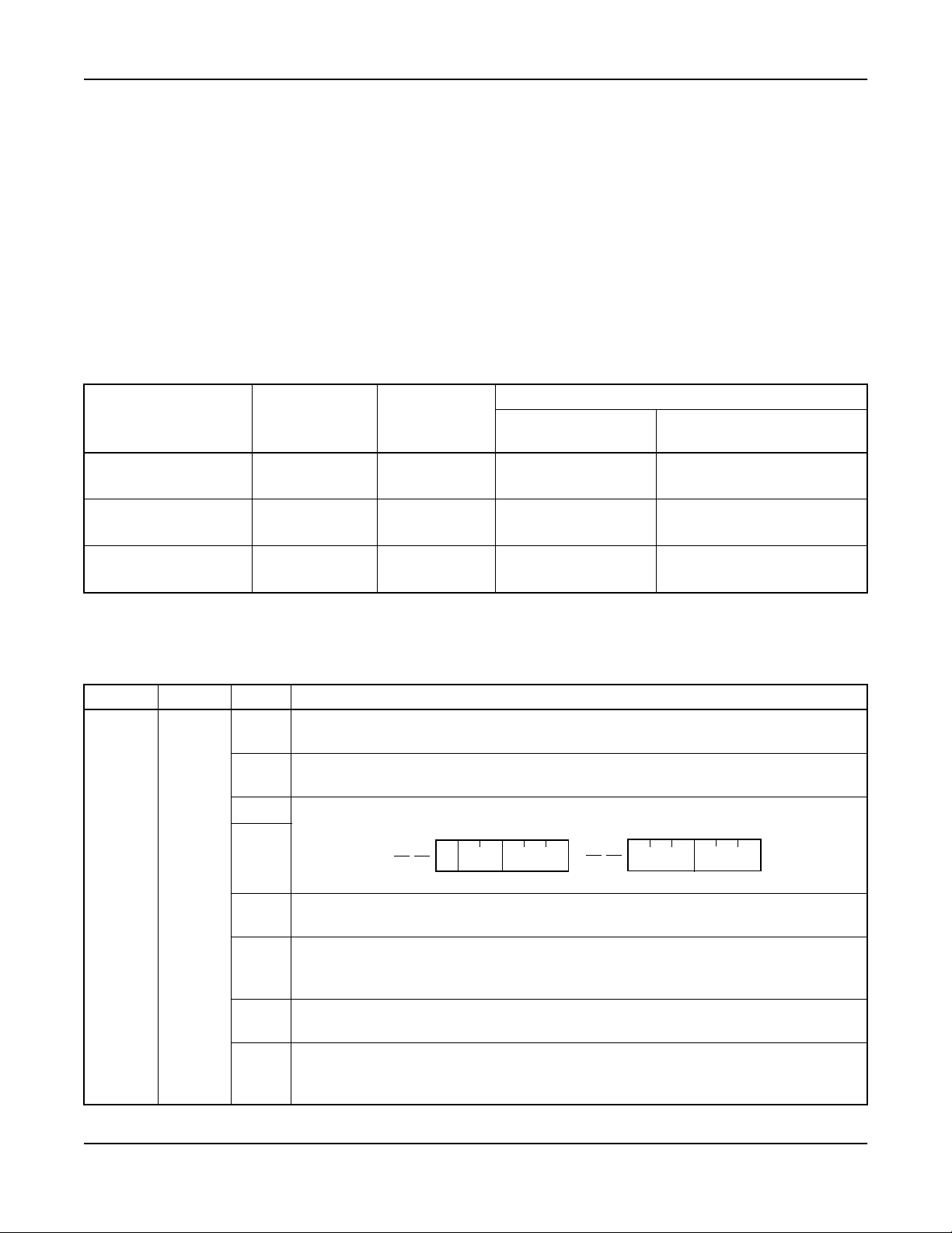
Called Number Display - Hotel Attendant Console C-71
Service Conditions (cont’d)
2. If the Attendant presses the SRC key while the called station number is displayed, the display changes to
the number of the calling party. The called station number cannot be displayed again.
3. While the called station number is displayed, the Attendant can transfer the c all to a desired station by
keying the destination number on the keypad. In this case, the called station number of that call cannot be
displayed again.
4. While the called station number is displayed, the Attendant can place the call on hold by pressing the
HOLD key.
5. While the called station number is displayed, the Attendant can set CALL PARK [C-29] service. The
called station number cannot be displayed again.
6. The Attendant can override the busy Guest station by pressing the associated loop key or TKSL key. The
called number and the associated station/route number are displayed on the Console.
CONSOLE DISPLAY
OVERRIDDEN
CONNECTION
PARTY
Station A - Station B S tation A LOOP Station B. No.
CONSOLE
KEY USED
STATION TRUNK
NO. AREA
ROOM INFORMATION
AREA
Station A name and
information
Station A - Trunk A Station A LOOP Trunk A. No.
Station A - Trunk A Trunk A TKSL Trunk A No.
Note: This service is activated, depending on the hotel system parameters.
Assignment Procedure
STEP CMND BIT EXPLANATION
b
b
b
b
SYS1
1
ASYD
INDEX
b
70
b
b
b
Called Number Displaywhen Call Forwarding to Console
0
0/1 = Out/In Service
Flashing display of Line Lockout on Console BLF
1
0/1 = In/Out Service
Route No. Display on Console
2
b
b
3
3
One digit dialing instead of SHF (DP TEL only)
4
0/1 = Not Required/Required
2
0
0:
TN RT TRK
b
0
Priority order for answeringvia ANSWER key
0 = Priority according to Type of Call
5
1 = Priority according to the order call termination
Announcement Trunks used for Delay Announcement - UCD service
6
0/1 = Common/perUCD group
Send Warning Tone to interrupted parties when Executive Right-of-Way service in
operation.
7
0/1 = Required/Not Required
Station A name and
information
Station A name and
information
b
3
2
1:
RT TRK
NEAX2400 IPX Hotel Feature Programming Manual
NDA-24304, Issue 1
Page 75
Page 90
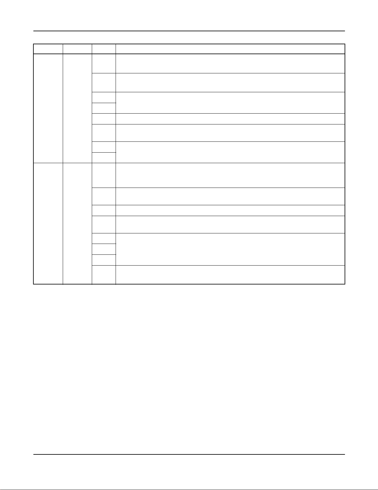
C-71 Called Number Display - Hotel Attendant Console
STEP CMND BIT EXPLANATION
b
b
SYS1
2
ASYD
INDEX
78
b
b
b
b
b
b
b
b
b
AHSY
3
INDEX
b
110
b
b
b
b
Calling and Intermediate StationNumber indication (D
0
0/1 = Out/In Service (Always assign “1”.)
Kind of Service Class indication (D
1
0/1 = Out/In Service (Always assign “1 ”.)
2
Not used
3
Fixed “0”
4
Name Display Service
5
0/1 = Out/In Service
6
Not used
7
term
)
Room key Interface
0: Interface is absent (STAY/OUT is displayed)
0
1: Interface is present (Key status is displayed)
Hotel-ATT Guest Information Service
1
0/1 = Not Required/Required
Not used
2
Called Number Display on the Hotel Console
3
0/1 = Out/In Service
4
Not used
5
6
Guest Name Display-D
7
0/1 = Out/In Service
term
, Guest Information Display-D
term
term
and Console)
/PMS Terminal
Page 76 NDA-24304, Issue 1
NEAX2400IPX HotelFeatureProgramming Manual
Page 91

Connecting Room Service C-72
C-72 Connecting Room Service
General Description
This feature allows the PMS to connect two rooms on a temporary basis to act as one room. One room will act as
the primary room and the other to act as a secondary room. If suite rooms are to be connected, the primary station
in the suite room arrangement is used for connecting room purposes.
Operating Procedure
CONNECTING ROOM SERVICE assignment is made through the PMS terminal.
Service Conditions
1. Dialing the primary room phone number rings both primary and secondary room phones. Dialing the
secondary room phone number rings the secondary phone only.
2. The primary station c an originate a c all when the secondary station is in use, and vice versa.
3. Only two rooms may be connected. If SUITE ROOMS are connected, then up to eight stations may be
connected.
4. Primary suite room numbers are assigned when suite rooms are connected. The status of all e ight stations
appears on the DSS lamps when the Console calls the connected suite rooms, if such status indicators are
assigned through system data.
5. Thisfeature essentiallyprovides for suite roomservice ona temporary basis for answering incomingcalls.
CHECK-IN/CHECKOUT [C-23], MA ID STATUS [M-22], MESSAGE WAITING [M-6],
AUTOMATIC WAKE-UP [A-10], DO NOT DISTURB [D-11] and ROOM CUTOFF [R-9] must be set
or reset independently for each room.
6. PMS message registration (billing) must be done se parately for connecting rooms.
7. When CONNECTING ROOM SERVICE is cancelled by the PMS terminal, the other hospitality statuses
remain unchanged. CONNECTING ROOM SERVICE is automatically cancelled when PMS declares the
status of these rooms as either Vacant or Out of Order.
8. CONNECTING ROOM SERVICE is also cancelled when MAID STATUS [M-22] sets the r oom or
primary rooms Ready to Sell or Out of Order. It is also cancelled when primary room or both rooms are
checked out (CHECK-IN/CHECKOUT [C-23]).
9. The CALLING STATION NUMBER DISPLAY [C-32] will display at either the primary or secondary
connecting room. In the case of connecting suite rooms, the display will be either the primary suite room
or the secondary suite room, depending on number dialed. For CONNECTING ROOM SERVICE, the
station number dialed will display regardless of the answering station.
10. There is no limit to the number of connecting room arrangements within a NEAX2400 IPX.
11. Three processing alternatives are available if the primary station in the connecting room is busy.
a.) The caller hears busy tone.
b.) The c all is transferred to the Console.
c.) The call rings an idle station.
12. When the DD override feature is used for a secondary room, room status displays secondary room
information with the primary room number.
NEAX2400 IPX Hotel Feature Programming Manual
NDA-24304, Issue 1
Page 77
Page 92

C-72 Connecting Room Service
Service Conditions (cont’d)
13. When the Console dials the primary station, the DSS keys a nd lamps are used in the operation. The status
of the connecting room phones appear on the DSS lamps. Ringing is generated at the connecting room
phones when the first DSS key is pressed or the START key is pressed. If a secondary phone DSS key is
pressed, only the corresponding secondary phone will ring. The DSS lamp on a busy connecting room
station will flash. The DSS lamp on an idle connecting room phone will show solid.
M1
S2
S3
S2
S3
S4
7500 7501 7502 7503 7510 7511 7512 7513
Primary
Secondary
Primary
Connecting Room
Primary
Secondary
Sub
Connecting Room
S4
M1
DSS/BLF keys on
Desk Con sole
Figure 3 Console Lamps Used for Connecting Suites
14. Ringing cycles are controlled by the line card. If suite r ooms are not serviced by a common line card, ring
will not be synchronized.
15. If digital remote units are used for c onnecting stations, ringing will be random and will not be
synchronized.
Assignment Procedure
STEP CMND BIT EXPLANATION
Don’t Disturb Override key on Console
b
0
0/1 = Out/In Service
Message WaitingLamp in Service
b
1
0/1 = Out/In Service
Language S ervice
b
2
0/1 = Out/In Service
SYS1
1
ASYD
INDEX
161
b
Screening Service
b
3
0/1 = Out/In Service
b
Not used
4
DSS (Direct Station Section) Keys on Console
5
0/1 = Ineffective/Effective
TimingStart using “#” Code
b
6
0/1 = Ineffective/Effective
TimingStart using “*” Code
b
7
0/1 = Ineffective/Effective
Page 78 NDA-24304, Issue 1
NEAX2400IPX HotelFeatureProgramming Manual
Page 93

Connecting Room Service C-72
STEP CMND BIT EXPLANATION
b
0
Fixed Data
b
1
b
Not used
2
b
AHSY
2
INDEX
111
b
b
b
AHSY
3
INDEX
185
b
b
AHSY
4
INDEX
188
b
Setting of Message Registration Data to be sent out to the PMS
3
b
4b3
0 0 : The pilot number is sent outin the case of Suite Room; the Ma in Room
4
b
5
b
6
7
b
0
1
b
2
b
3
b
4
b
5
b
6
b
7
0 1 : The stationNumber of each station within the room is sent out.
Not used
Connecting Room
0/1 = Out/In S ervice
Not used
Suite Room/Connecting Room Status Display
0/1 = Out/In S ervice
Not used
StationNumberissentoutinthecaseofConnectingRoom.
Processingfor Suite Room Station/Connecting Room Station Busy
b
0
1b0
00=BusyTone
0 1 = An idle station w ithin the room is called
1
b
2
b
3
b
4
1 0 = The call is transferred to the Console if the caller is not the console
operator.
Fixed Data
Not used
When a call terminates to the Double Suite Room
b
0 = All stations ring simultaneously
5
1 = Alternately between Primary Suite and Secondary Suite
b
Fixed Data
6
Suite Roomin Service
7
0/1 = Out/In S ervice
NEAX2400 IPX Hotel Feature Programming Manual
NDA-24304, Issue 1
Page 79
Page 94

C-72 Connecting Room Service
STEP CMND BIT EXPLANATION
b
0
b
1
b
Not used
2
b
3
b
4
Suite R oom Individual Station Ca lling
AHSY
5
INDEX
189
b
0 = A Suite Room individual stationcan be called from a Guest Station, Administration
b
5
Station, and Console.
1 = A Suite Room individualstationcanbe called from a SpecialAdministrationStation
and Console.
Ringing at time of generalcalling in theConnecting Room or Suite Room stations
0 = Ringing all stations
6
1 = Ringing the station in the main room for the Connecting Room; ringing the
Primary station for a Suite Room
Number to be dialed for a general calling of the stations in the Suite Room
b
0 = Primary Station Number or Pilot (Phantom) Number
7
1 = Only Pilot (Phantom) Number
Page 80 NDA-24304, Issue 1
NEAX2400IPX HotelFeatureProgramming Manual
Page 95

Call Information Display C-147
C-147 Call Information Display
General Description
This feature a llows the following information to be displayed on the Guest room D
for Guest stations.
Calling/Called Station
AUTOMATIC WAKE-UP - D
term
ALERT SERVICE [A-57]
DO NOT DISTURB - D
term
DIRECT DATA ENTRY - STATION [D-107]
MESSAGE WAITING [M-6]
MAID STATUS [M-22]
ROOM CUTOFF [R-9]
2ND WAKE-UP CALL - S AM E GUEST STATION [S-128]
Operating Procedure
1. Calling/Called Station Display
a.) During a call with another Guest station in progress:
term
sLCD.D
[A-10D]
[D-11D]
term
may be used
(Time and Date)
b.) During a call with Administration Station in progress:
ADM XXXX
(Time and Date)
A six digit station displays as AMXXXXXX
c.) During a call with the Console in progress:
(Time and Date)
d.) During a a call through Central Office in progress:
HH:MM DDD X
(Time and Date)
HH:MM indicates lapsed time,
X indicates trunk type (1-3digits)
-OR-
HH:MM FX X
(Time and Date)
XXXX
>>>
>>>
OPR
>>>
>>>
>>>
NEAX2400 IPX Hotel Feature Programming Manual
NDA-24304, Issue 1
HH:MM WATS X
(Time and Date)
>>>
Page 81
Page 96

C-147 Call Information Display
Operating Procedure (cont’d)
e.) During a call through Tie line in progress:
HH:MM TIE X
(Time and Date)
>>>
-OR-
HH:MM CCSA X
(Time and Date)
>>>
2. For other display services, see each service feature description.
Service Conditions
1. When the Guest name two-line display isprovided by the system parameters,the time display(lower line)
disappears during a call.
2. When originating a call using the ISDN terminal, the charging information is not displayed.
Assignment Procedure
STEP CMND EXPLANATION
1 AGST
Assign Guest Station Data (Hotel System)
TEC = 12/18, Room Class = 15 (Guest Station)
STEP CMND BIT EXPLANATION
Assign Hotel System Parameters
b
b
2
AHSY
INDEX 77
b
b
LCD Indicationof Wake Up time on the D
0
0/1 = -/Remains lit
LCD Indication of “DD” (Do Not Disturb) on the D
1
0/1 = -/Remains lit
LCD Indicationof “RC” (Room Cutoff) on the D
2
0/1 = -/Remains lit
LCD Indicationof 2nd Wake-Up time on the D
3
0/1 = -/Remains lit
b
4
b
5
Not used
b
6
b
7
term
term
term
term
STEP CMND EXPLANATION
Assign D
3AKYD
Type:Function:WAKE UP SE T (WUS) [87] Type:Function:ROOM CUTOFF SET [91]
term
Key data
Type:Function:DO NOT DISTURD SET [89] Type:Function:MESSAGE WAITING SET [93]
Related Commands: AGCL, AGSL
Page 82 NDA-24304, Issue 1
NEAX2400IPX HotelFeatureProgramming Manual
Page 97

Do Not Disturb D-11
D-11 Do Not Disturb
General Description
This feature allows the Console, PMS terminal, Front Desk Terminal, S pecial Administration Station, or Guest
Station to temporarily place individual stations into a mode that blocks incoming calls. Outgoing calls may still be
placed from stations in DO NOT DISTURB (DD) mode.
Operating Procedure
To set DO NOT DISTURB from the Console o r F ro nt Desk Terminal
1. Press the DD (set) key. The associated lamp illuminates.
2. Dial the station number. The console displays the station number.
3. Press the ENTERkey. The lamp flashes to confirm that DD is set.
4. Press the EXIT key. The lamp and station display are extinguished.
To cancel DO NOT DISTURB from the Console or Front Desk Terminal
1. Press the DD (reset) key. The associated lamp illuminates.
2. Dial the station number. The console displays the station number.
3. Press the ENTERkey. The lamp flashes to confirm that DD cancellation.
4. Press the EXIT key. The lamp and station display are extinguished.
To set DO NOT DISTURB from Special Administration Station
1. Lift handset or press the SPEAKER key. Receive dial tone.
2. Dial Enhanced DO NOT DISTURB access code. (If ID c ode is required, dial ID code upon receiving
second dial tone.) Receive special tone.
3. Dial the station number. Receive service set tone.
4. Repeat S tep 3 for as many Guest rooms a s required.
To cancel DO NOT DISTURB from S pecial Administration Station
1. Lift handset or press the SPEAKER key. Receive dial tone.
2. Dial Enhanced DO NOT DISTURB cancel code. (If ID c ode is required, dial ID code upon receiving
second dial tone.) Receive special dial tone.
3. Dial the station number. Receive confirmation tone.
To set DO NOT DISTURB from Guest S t ations
1. Lift handset. Receive dial tone.
2. Dial the DD set code. Receive service set tone.
3. Hang up.
To cancel DO NOT DI ST URB from Guest Stations
1. Lift handset. Receive dial tone.
2. Dial the DD cancel code. Receive service set tone.
3. Hang up.
To obtain a printout of stations in the DO NOT DISTURB state, refer to the AUDIT REPORTS [A-26] feature
description.
NEAX2400 IPX Hotel Feature Programming Manual
NDA-24304, Issue 1
Page 83
Page 98

D-11 Do Not Disturb
Operating Procedure (cont’d)
Note: For the Console and Front Desk Terminal only:
If an error is made in the c ourse of key operations, press the CLEAR key and continue from Step 2 (station
dialing).
When setting or cancelling DO NOT DISTURB for two or more stations at the same time, follow the above
operating procedure for the first station. Perform Steps 2 and 3 for the remaining stations, then Step 4 to
exit from the service mode.
DIRECT SERVICE SET/RESET [D-25] is also available for this feature.
Service Conditions
1. Setting and cancelling of DO NOT DISTURB is performed by key ope rations at the C onsole, PMS
terminal, Guest station, Special Administration Station, or Front Desk Terminal.
2. An incoming call to a station in DO NOT DISTURB mode is routed to a reorder tone connection, a “Do
Not Disturb” announcement, or the Console, depending on the system data.
3. After the Guest has checked out (CHECK-IN/CHECKOUT [C-23]), DO NOT DISTURB information is
automatically erased.
4. A station in DO NOT DISTURB mode will be rung for AUTOMATIC WAKE-UP [A-10] service or for
ALERT SERVICE [A-57].
5. If a call to a station in DO NOT DI STURB mode is routed to the Console, the Attendant may be able to
connect both stations for temporary service cancellation by pressing the DD OVER key. This aspect of
the DO NOT DISTURB feature is programmable into system data.
6. DO NOT DISTURB is provided for Guest room stations only.
7. When a station in a suite sets DO NOT DISTURB, a ll stations in that suite are placed in the DD mode.
8. Station in DD mode can receive calls from specific trunk routes or stations through system data
assignment.
9. Guest “Boss” and “Secretary” rooms override DD mode for calls between assigned stations.
10. When setting DO NOT DISTURB from Special Adm inistration Station, no check is made to see if dialed
station is in DO NOT DISTURB mode or not; subsequent DO NOT DISTURB set/cancel is accepted.
11. DO NOT DISTURB set by Special Administration Station c an be cancelled by Guest station, and vice
versa.
Page 84 NDA-24304, Issue 1
NEAX2400IPX HotelFeatureProgramming Manual
Page 99

Do Not Disturb D-11
Assignment Procedure
STEP CMND BIT EXPLANATION
b
Hotel Feature required (Fixed Data)
0
b
Hotel Service kind (Fixed Data)
1
Length of Room Status Memory
b
2
0/1 = 8 byte/24 byte
SYS1
1
ASYD
INDEX
160
SYS1
2
ASYD
INDEX
161
b
b
b
b
b
b
b
b2
b
b
b
b
b
b
b
3
Pattern of Key Arrangement on Attendant Console
(Refer to Figure 4) (Usually, 00)
4
GuestName Service
5
0/1 = Out/In Service
Numbering Plan Data Table of Guest and Administration stations
6
0/1 = Separate/Common
Fixed “0”
7
Don’t Disturb Override key on Console
0
0/1 = Out/In Service
Message Waiting Service
1
0/1 = Out/In Service
Language Service
0/1 = Out/In Service
Screening Service
3
0/1 = Out/In Service
Not used
4
DSS (Direct Station Section) Key on Console
5
0/1 = Ineffective/Effective
TimingStart using “#” Code
6
0/1 = Ineffective/Effective
TimingStart using “*” Code
7
0/1 = Ineffective/Effective
Destination of connection when a connection between Gue st stations is restricted.
0
b1b
0
0 0 = ROT 1 0 = Announcement
1
01=ATT 11=–
b1b
0
b
Destination of connection when Room Cutoff is assigned.
2
b3b
2
SYS1
3
ASYD
INDEX
b
b
162
b
b
b
NEAX2400 IPX Hotel Feature Programming Manual
NDA-24304, Issue 1
0 0 = ROT 1 0 =Announcement
3
01=ATT 1 1=–
Assignment of destination for Do Not Disturb.
4
b5b
4
0 0 = ROT 1 0 =Announcement
5
01=ATT 1 1=–
Tone to be given when a wake-up call is answered.
6
b7b
6
0 0 = Music On Hold 1 0 = –
7
0 1 = Announcement 1 1 = –
b3b
b5b
b7b
2
4
6
Page 85
Page 100
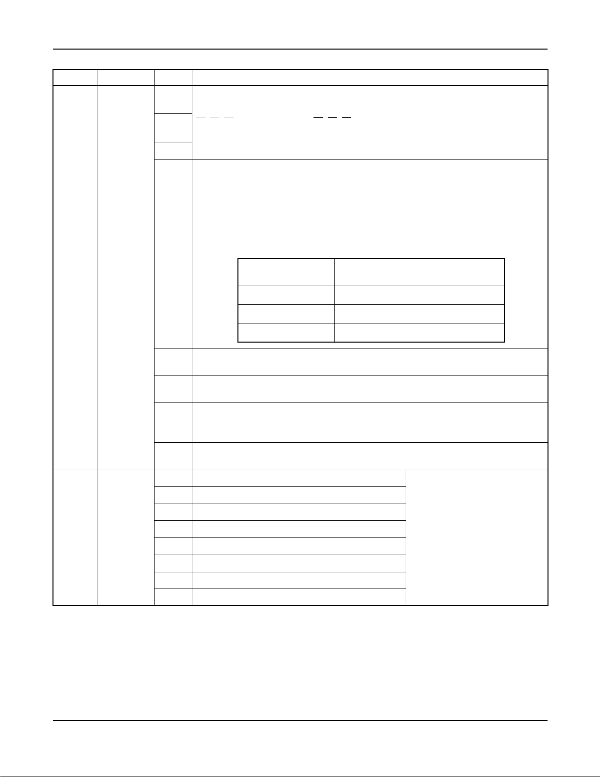
D-11 Do Not Disturb
STEP CMND BIT EXPLANATION
Room status data (b2,b1,b0) to be set at the time of C heckout
b
0
b2b1b
0 0 0= – 0 1 0 = Cleaned
b
1
0 0 1= To be Cleaned 0 1 1 = Ready for Occupancy
Note:
b
2
0
Do not assign other data.
b2b1b
0
Assignment of Re striction Method in Do N ot Disturb Status
0/1 = Restricted/Restriction Method according to RSC
Note:
If unconditional restriction is set as per the OG restriction and IC
restrictioninformation, or if OG restriction and IC restriction are set to
Guest stations, the present Route Restriction Class is temporarily
replaced with RSC 13-15, and whether restriction is executed or not is
b
SYS1
4
ASYD
INDEX
3
170
selected from the Rest riction Table.
ROUTE RESTRICTION
CLASS (RSC) CONDITION
13 RoomCutoff
14 Do Not Disturb
15 Room Cutoffand Do Not Disturb
Timing Start
b
4
0/1 = Not Required/Required
SHF from a Guest Station while talking
b
5
0/1 = Effective (goes to ORT)/Ineffective (Goes to ATTCON)
Day/Night Change of RSC
b
0 = Time zone changing per Day/Night Change Table (ADNR)
6
1 = By NIGHT key of the ATT
Message Registration from Hotel Processor
b
7
0/1 = Yes/No
b
Message Waiting
0
b
Message Registration
1
b
Do Not Disturb, Room Cutoff
SYS1
5
ASYD
INDEX
172
2
b
Room Status
3
b
Automatic Wake up, Group Announcement
4
b
Room Change, Room Swap
5
b
Room Data Change
6
b
Not used
7
Data transfer to/from PMS
when executing the service.
0/1 = Not to be executed/To be
executed
Page 86 NDA-24304, Issue 1
NEAX2400IPX HotelFeatureProgramming Manual
 Loading...