

Page 1

NDA-24310
ISSUE 1
STOCK # 200799
®
Hotel Features and Specifications
OCTOBER, 2000
NEC America, Inc.
Page 2

The informationcontained in this document is specific to D
term
Series E only.
Throughout this document, references to “Console” or “Attendant Console”
imply a Hotel Console. Most features described in this manual require a Hotel
Console. However, somefeatures(includingA-57, A-73,I-23, P-34, and V-16)
can also be performed using a Business Console.
Minimum firmware may be required. Contact NEC Engineering for additional
information.
NEC America, Inc. reserves the right to change the specifications, functions, or
features, at any time, without notice.
NEC America, Inc. has prepared this document for use by its employees and
customers. The information contained herein is the property of NEC America,
Inc. and shall not be reproduced without prior written approval from NEC
America, Inc.
NEAX
®
and D
term®
are registered trademarks of NEC Corporation.
Copyright 2000
NEC America, Inc.
Printed in the U.S.A
Page 3

PAGE No.
i 1
ii 1
iii 1
iv 1
v 1
vi 1
vii 1
viii 1
1 1
2 1
3 1
4 1
5 1
6 1
7 1
8 1
9 1
10 1
11 1
12 1
13 1
14 1
15 1
16 1
17 1
18 1
19 1
20 1
21 1
22 1
23 1
24 1
25 1
26 1
27 1
28 1
29 1
30 1
DATE OCTOBER, 2000 DATE DATE DATE
DATE DATE DA TE DATE
12345678
ISSUE 1 ISSUE 2 ISSUE 3 ISSUE 4
ISSUE 5 ISSUE 6 ISSUE 7 ISSUE 8
ISSUE No.
PAGE No.
31 1
32 1
33 1
34 1
35 1
36 1
37 1
38 1
39 1
40 1
41 1
42 1
43 1
44 1
45 1
46 1
47 1
48 1
49 1
50 1
51 1
52 1
53 1
54 1
55 1
56 1
57 1
58 1
59 1
60 1
61 1
62 1
63 1
64 1
65 1
66 1
67 1
68 1
12345678
ISSUE No.
NEAX2400 IPX
Hotel Features and Specifications
Revision Sheet 1/2
NDA-24310
Page 4
PAGE No.
69 1
70 1
71 1
72 1
73 1
74 1
75 1
76 1
77 1
78 1
79 1
80 1
81 1
82 1
83 1
84 1
85 1
86 1
87 1
88 1
89 1
90 1
91 1
92 1
93 1
94 1
95 1
96 1
97 1
98 1
99 1
100 1
101 1
102 1
103 1
104 1
105 1
106 1
DATE OCTOBER, 2000 DATE DATE DATE
DATE DATE DA TE DATE
12345678
ISSUE 1 ISSUE 2 ISSUE 3 ISSUE 4
ISSUE 5 ISSUE 6 ISSUE 7 ISSUE 8
ISSUE No.
PAGE No.
107 1
108 1
109 1
110 1
111 1
112 1
113 1
114 1
115 1
116 1
117 1
118 1
119 1
120 1
121 1
122 1
123 1
124 1
125 1
126 1
127 1
128 1
12345678
ISSUE No.
NEAX2400 IPX
Hotel Features and Specifications
Revision Sheet 2/2
NDA-24310
Page 5

NDA-24310
ISSUE 1
OCTOBER, 2000
NEAX2400 IPX
Hotel Features and Specifications
Feature List
Page
Introduction.............................................................. 1
NumberingPlan .......................................................... 3
DescriptionofServiceFeatures.............................................. 9
A-10 AutomaticWake-Up............................................... 11
A-10D Automatic Wake-Up D
A-15 AnnouncementService ............................................ 21
A-25 Attendant Console With Hotel Functions ............................... 22
A-26 AuditReports .................................................... 24
A-48 AutomaticMessageWaitingLampOff................................. 26
A-57 AlertService..................................................... 27
A-58 Automatic Wake-up - Hotel Attendant . ................................ 29
A-73 AutomaticMultipleAttendantRecall .................................. 31
A-74 Answering Camp-On/Call Hold Calls By Switchhook Flash ................. 33
A-75 AutomatedGuestStationVoiceMailRetrieval .......................... 35
B-26 Busy Status - Hotel Attendant . . . .................................... 36
C-19 CalendarDisplay ................................................. 38
C-23 Check-In/Checkout................................................ 39
C-32 Calling Station Number Display . . .................................... 40
C-71 Called Number Display - Hotel Attendant Console . ...................... 42
C-72 ConnectingRoomService .......................................... 44
C-147 CallInformationDisplay............................................ 46
D-11 DoNotDisturb ................................................... 48
D-11D Do Not Disturb - D
D-15 Day/NightClassofService ......................................... 52
D-23 DirectPageConnection............................................ 53
D-24 DirectPaging .................................................... 54
D-25 DirectServiceSet/Reset ........................................... 55
D-26 DirectStationSelection ............................................ 56
D-88 DirectoryAssistanceInterface ....................................... 57
D-89 DirectSelection-Outside .......................................... 58
D-105D D
term
WithHotelFunction .......................................... 59
D-107 DirectDataEntry-Station .......................................... 62
D-150 DoubleSuiteRoom ............................................... 63
D-151 DD/MWLampControl ............................................. 65
E-21 Emergency Call Monitor - Attendant . . ................................ 66
G-1 Guest/AdministrativeService........................................ 67
term
.......................................... 15
term
............................................. 50
NEAX2400 IPX Hotel Features and Specifications
NDA-24310, Issue 1
Page i
Page 6

Feature List (Continued)
Page
G-4 GroupServiceThroughPMS........................................ 68
G-5 GuestNameDisplayThroughPMS................................... 70
G-6D Guest Name Display - D
G-7D Guest Information Display - D
term
......................................... 71
term
.................................... 74
G-8 Guest Information Display - Hotel Attendant Console . . . .................. 76
G-9 GuestInformationDisplay-PMSTerminal ............................. 77
G-11 Guest Room Calling - Hotel Attendant . ................................ 78
G-21 GroupRestriction................................................. 79
G-24 Guest Station - D
term
.............................................. 83
H-8 House Phone/Hot Line ............................................. 84
H-22 HotelFeatureTransparencyOverCCIS ............................... 85
I-23 Inter-PositionTransfer2............................................ 90
L-27 Language Service . . .............................................. 91
M-6 MessageWaiting ................................................. 92
M-22 MaidStatus ..................................................... 94
M-51 Manual Switching Of C.O. Incoming Call Destination . . . .................. 97
M-68 MaidStatus-Answerback .......................................... 98
O-6 Off-hookAlarm................................................... 99
O-9 OvertimeCall .................................................... 100
P-8 PrinterControl-HotelAttendantConsole .............................. 101
P-27 PMSInterface-BISYNC ........................................... 102
P-29 PMSInterface ................................................... 103
P-34 PagingConsole .................................................. 105
R-9 RoomCutoff..................................................... 106
R-10 RoomStatus .................................................... 108
R-17 RoomNumbering................................................. 109
S-17 SplitAccesstoOutgoing ........................................... 110
S-32 Screening....................................................... 111
S-49 ServiceCallRouting............................................... 112
S-74 SecretarialService-GuestStation ................................... 113
S-75 SuiteRoomService ............................................... 116
S-128 2ndWake-upCall-SameGuestStation............................... 119
T-13 TollTerminalAccess .............................................. 122
T-21 TimingStart ..................................................... 123
V-16 VoiceMailServiceViaMessageCenterInterface(MCI)................... 124
W-2 Wake-up Announcement - Headstart . . ................................ 126
Page ii NDA-24310, Issue 1
NEAX2400 IPX Hotel Features and Specifications
Page 7

List of Figures
Page
Figure1 KeyAllocationsofDeskConsole................................... 23
Figure 2 Display Area of Attendant Console and Desk Console .................. 42
Figure 3 Console Lamps Used for Connecting Suites.......................... 45
Figure 4 Key Pattern on the Attendant Console . . . ........................... 55
Figure5 KeyPatternontheDeskConsole.................................. 55
Figure 6 Example of 16-Button D
term
onaFrontDeskConsole.................. 60
Figure 7 Example of Single/Double Suite Room . . . ........................... 63
Figure 8 LCD Display on Special Administration Station D
term
................... 71
Figure 9 DSS Key/Station Correspondence and Lamp Indications. . . ............. 78
Figure 10 Example of Display for Call Origination - from Attendant Console
andDeskConsole.............................................. 85
Figure 11 Example of Display for Call Origination from D
term
..................... 85
Figure 12 Call Termination on Attendant Console, Desk Console,
and Special Administration D
term
................................... 86
Figure 13 Example of Service Feature Setting - Attendant Console
andDeskConsole.............................................. 86
Figure 14 Check-In/Checkout Keys Replaced by Secretary Service
Set/Reset(SCS,SCR)........................................... 115
Figure 15 DSS Bu sy Lamps on Attendant Console and Desk Console. ............. 117
NEAX2400 IPX Hotel Features and Specifications
NDA-24310, Issue 1
Page iii
Page 8

List of Tables
Page
Table1 DialAccessNumbersforAdministrationStation....................... 3
Table2 DialAccessNumbersforGuestStation ............................. 3
Table3 SpecialServiceAccessNumbers.................................. 4
Table4 TrunkAccessNumbers.......................................... 5
Table5 DialAccessNumberingPlanforAdministrationStation................. 6
Table6 DialAccessNumberingPlanforGuestStation........................ 7
Table7 AuditReport................................................... 24
Table 8 Standard Service Abbreviations on D
term
............................ 61
Table9 AvailableHospitalityServiceOverCCIS............................. 87
Page iv NDA-24310, Issue 1
NEAX2400 IPX Hotel Features and Specifications
Page 9
NEAX2400 IPX Hotel Features
LEGEND
X – Available
— – Not Applicable
N – Not Available
→ – Feature carried over to next software series
Index Feature Description
A-10 Automatic Wake-Up
A-10D Automatic Wake-Up D
term
A-15 Announcement S ervice
A-25 Attendant C onsole With Hotel Functions
A-26 Audit Reports
Non-
Network
XX
XX
X
X
XX
FCCS
—
N
A-48 Automatic Message Waiting Lamp Off XX
A-57 Alert Service
A-58 Automatic Wake-up - Hotel Attendant
A-73 Automatic Multiple Attendant Recall
A-74 Answering C amp-On/Call Hold Calls B y Switchhook Flash
A-75 Automated Guest Station Voice Mail Retrieval
X
XX
X
X
X —
N
N
—
B-26 Busy Status - Hotel Attendant
C-19 Calendar Display
C-23 Check-In/Checkout
C-32 Calling Station Number Display
C-71 Called Num ber Display - Hotel Attendant Console
XX
X
XX
XX
XX
C-72 Connecting Room Service X N
C-147 Call Information Display
D-11 Do Not Disturb
term
D-11D
Do Not Disturb - D
Note: Different from Business Feature.
X N
XX
XX
D-15 Day/Night Class of Service X N
D-23 Direct Page Connection
D-24 Direct Paging
D-25 Direct Service Set/Reset
D-26 Direct Station S election
D-88 Directory Assistance Interface
D-89 Direct Selection - Outside
term
D-105D D
With Hotel Function XX
D-107 Direct Data Entry - Station
X —
X
XX
X
X
X —
X
—
—
—
N
N
NEAX2400 IPX Hotel Features and Specifications
NDA-24310, Issue 1
Page v
Page 10
NEAX2400 IP X Hotel Features (Continued)
LEGEND
X – Available
— – Not Applicable
N – Not Available
→ – Feature carried over to next software series
Index Feature Description
D-150 Double Suite Room
D-151 DD/MW Lamp Control
E-21 Emergency Call Monitor - Attendant
G-1 Guest/Administrative Service
G-4 Group Service Through PMS
Non-
Network
X
XX
X
XX
XX
FCCS
N
N
G-5 Guest Name Display Through PMS XX
G-6D GuestName Display - D
G-7D Guest Information D isplay - D
G-8 Guest Information Display - Hotel Attendant Console
G-9 Guest Information Display - PMS Terminal
G-11 Guest Room Calling - Hotel Attendant
term
term
XX
X
X
X
XX
N
N
N
G-21 Group Restriction X N
G-24 Guest Station - D
term
H-8 House Phone/Hot Line
H-22 Hotel Feature Transparency Over CCIS
I-23 Inter-Position Transfer 2
L-27 Language Service
XX
X
X
X
XX
—
—
N
M-6 Message Waiting XX
M-22 Maid Status XX
M-51 Manual S witching Of C.O. Incoming C all Destination
M-68 Maid Status - Answerback
O-6 Off-hook Alarm
O-9 Overtime Call
X
X
XX
XX
N
N
P-8 Printer C ontrol - Hotel Attendant Console XX
P-27 PMS Interface - BISYNC XX
P-29 PMS Interface
P-34 P aging Console
R-9 Room Cutoff
R-10 Room Status
XX
X
XX
XX
—
R-17 Room Numbering X —
S-17 S plit Access to Outgoing
NEAX2400 IPX Hotel Features and Specifications
Page vi NDA-24310, Issue 1
XX
Page 11
NEAX2400 IP X Hotel Features (Continued)
LEGEND
X – Available
— – Not Applicable
N – Not Available
→ – Feature carried over to next software series
Index Feature Description
S-32 Screening
S-49 S ervice Call Routing
S-74 Secretarial Service - Guest Station
S-75 S uite Room Service
S-128 2nd Wa ke-up Call - Same Guest Station
Non-
Network
X
XX
X
X
XX
FCCS
N
N
N
T-13 Toll Terminal Access XX
T-21 Timing Start XX
V-16 Voice Mail Service Via Message Center Interface (MCI)
W-2 Wake-up Announcement - Headstart
XX
X
N
NEAX2400 IPX Hotel Features and Specifications
NDA-24310, Issue 1
Page vii
Page 12

This page is for your notes.
Page viii NDA-24310, Issue 1
NEAX2400 IPX Hotel Features and Specifications
Page 13

Introduction
Introduction
General Description
This manual explains the Office Data Design of the Hotel S ystem, the Numbering Plan and a description of Service
features.
How to Follow the Manual
This manual is organized as follows:
• Numbering Plan
This section explains the numbering plan in the hotel system.
• Description of Service F eatures
This section explains how to use the hotel service features.
NEAX2400 IPX Hotel Features and Specifications
NDA-24310, Issue 1
Page 1
Page 14

This page is for your notes.
Page 2 NDA-24310, Issue 1
NEAX2400 IPX Hotel Features and Specifications
Page 15
Numbering Plan
Numbering Plan
Access Codes for various service features are determined according to the Dial Access Numbering Plan. This
chapter explains the Numbering Plan, and commands related to the Num bering Plan in the Hotel System.
Three types of Dial Access Numbers
• Station Access Numbers
• SpecialService Access Numbers
• Trunk Access Numbers
Basic Knowledge of Dial Access Numbers
This section explains the procedure for determining these Dial Access numbers and precautions.
1. A Dial Access Number consists of an Access Level and a Number of Digits a s shown below:
Number of Digits (maximum 6 digits)
ABCDEFDial Access Number:
Access Level (0 through 9, *, #)
2. For Hotel Systems, the service to be performed is determined according to the specific Dial Access
Number.
3. The Hotel System can have two Numbering Plan Development tables; one is for Administration stations
and the other for Guest stations. Therefore, the D ial Access Number for Administration stations and the
Dial Acc ess Number for Gue st stations can be provided independently. For example:
• Dial Access Numbers for Adm inistration Station
Table 1 Dial Access Numbers for Administration Station
DIAL ACCESS NUMBER ACCESS TO
“0” Split Access To Outgoing (Operator Call)
“10” Speed Calling - System
“12” Call Hold
“2XXXX” Guest Station (4 or 5 digits) of Main Building
“3XXXX” Guest Station (4 or 5 digits) of Annex
“4XXX” Administration Station (4 digits)
“5XXX” Special Administration (4 digits)
“8X” 2-Digits Trunk
“9” C.O. Trunk
“6” and “7” Vacant Level
• Dial Access Numbers for Guest S tation
Table 2 Dial Access Numbers for Guest Station
DIAL ACCESS NUMBER ACCESS TO
“0” Split Access To Outgoing ( Special Administration Station (STN 5000) Call
NEAX2400 IPX Hotel Features and Specifications
NDA-24310, Issue 1
Page 3
Page 16
Numbering Plan
Table 2 Dial Access Numbers for Guest Station (Continued)
DIAL ACCESS NUMBER ACCESS TO
“13” Automatic Wake Up; Set
“14” Automatic Wake Up; Cancel
“2XXXX” Guest Station (4 or 5 digits) of Main Building
“3XXXX” Guest Station (4 or 5 digits) of Annex
“7” Floor Service
“9” C.O. Trunk
“4”, “5”, “6”, and “8” Vacant Level
Note: For the Access Level (1st digit of the Dial Access numbers) different numbers are assigned for Station
Access numbers, Special Service Access numbers, and Trunk Access numbers.
Station Access Numbers
1. One through six-digit station numbers are supported.
2. The NEAX2400 IPX c an pr ovide Timing Start Service. The Timing Start Service allows single-digit and
multi-digit stations to use the same Access levels. For example:
2101: Guest Station Number of No. 1 R oom on the 1st floor of the main building.
21001: Guest Station Number of No. 1 Room on the 10th floor of the main building.
3101: Guest Station Number of No. 1 R oom on the 1st floor of the annex.
31001: Guest Station Number of No. 1 Room on the 10th floor of the annex.
3. The same station number cannot be assigned twice within the same NEAX2400 IPX, even if it is assigned
to different tenants or to an Administration Station and a G uest Station.
Special Service Access N umbers
1. SpecialService Access numbers of one through six digits can be assigned for each Access Level. Usually,
one through three digits are used.
2. The Hotel System can provide the Same Number Access (Split Access To Outgoing) service. The Same
Number Access service can provide both Administration and Guest stations with the different service
featureby the same number. It can also provide the same or a different service featureby the same number
according to Tenant Class, Route R estriction Class (RSC) and Service Feature Class (SFC) concerned.
Table 3 Special Service Access Numbers
DIAL
CODE
SERVICE FEATURE FO R
ADMINISTRATION S T ATION
SERVICE FEATURE FO R
GUEST STATION
“0” Operator Call Special Administration Station Call
3. The Hotel System c an provide the Floor Service. The Floor Service is a service to call the Room Service
station on each floor by the same Access code. For example:
• Guest Station on the 1st Floor of the main building:
dial “7” Calling
→ Room S ervice Station (STN 4801) on the 1F
• Guest Station on the 2nd Floor of the main building
dial “7”
→ Calling Room Service Station (STN 4802) on the 2F
• Guest Station on the 3rd F loor of the main building
dial “7”
→ Calling Room Service Station (STN 4803) on the 3F
Table 4 shows a listing of special services which require Access numbers.
Page 4 NDA-24310, Issue 1
NEAX2400 IPX Hotel Features and Specifications
Page 17
Numbering Plan
Note: In a case where both Entry and Cancel are specified for the same special service, different Access numbers
must be assigned for Entry and for Cancel.
Trunk Access Numbers
1. Trunk Access numbers ranging from one through six (1-6) digits m ay be assigned on an individual basis.
Usually, 1-3 digits are used.
Table 4 Trunk Ac cess Numbers
NAME OF SPECIAL SERVICE NAME OF SPECIAL SERVICE
Account Code Dial C all Forwarding - D on’t Answer - C ancel
Attendant Manua l Override Call Hold
Authorization Code/Forced Account Code Dial Call Park Access Code
Automatic Wake Up - Set Call Park Local Retrieval Code
Automatic W a ke Up - Cancel Call Park Remote Retrieval C ode
Busy Out - Entry (UCD) Call Pickup
Busy Out - Cancel (UCD) Call Pickup - Direct
Call Back - Entry Call Waiting
Call Back - Cancel Data Privacy - Entry
Call Forwarding - All Calls - Entry Data Privacy - Cancel
Call Forwarding - All Calls - Cancel Dial Access to Attendant
Call Forwarding - Busy Line - Entry Executive Right-of-Way
Call Forwarding - Busy Line - Cancel Faulty Trunk Report
Call Forwarding - Don’t Answer - Entry Flash Signal S ending (CAS M ain S tation)
Floor Service Priority Call 1
Group Announcement - Entry Priority Call 2
Group Announcement - Cancel Priority Call 3
Guest/Administration Service Priority Paging
Hotel Service Speed Calling Access
Individual Speed Calling: Entry Same Number Access
Individual Speed Calling: Access TAS Answer
Individual Trunk Access Trunk Queuing: Entry
Line Load Control: Entry Trunk Queuing: Cancel
Line Load Control: Cancel Voice Call
Message Reminder
2. Trunk Access numbers are required on an individual route basis.
NEAX2400 IPX Hotel Features and Specifications
NDA-24310, Issue 1
Page 5
Page 18
Numbering Plan
3. When Least Cost R outing (LCR) is utilized, LCR Access is regarded as access to an individual route;
therefore an Access Number must be assigned.
4. If Answer Service is provided for Speaker and/or Radio Paging, a Paging Answer code must be assigned.
Examples of a Dial Access Numbering Plans are shown in Table 5 and Table 6.
Table 5 Dial Access Numbering Plan for Administration Station
ACCESS NUMBER FUNCTION REMARKS
0 Same Number Access (Dial Access to Attendant) Operator Call
10 Call Hold
11 Call Back (Entry) Cancel Number is “19”
12 Executive Right-of-Way
13 Speed Calling System
14
15
16
Vacant Numbers
17
18
19 Call Back (Cancel) Entry Number is “11”
2000 - 2018 4-digit Adm inistration Station Number
3000 - 3011 4-digit Guest S tation Number
4
5
6
Vacant Numbers
7
80 Vacant Numbers
81 Access to Area A Route Number: 2
82 Access to Area B R oute Num ber: 3
83 Access to Area C R oute Num ber: 4
84 Access to Area D Route Number: 5
85 Access to Area E Route Number: 6
86
Vacant Numbers
87
88 Access to Paging Equipment Route Number: 10
Page 6 NDA-24310, Issue 1
NEAX2400 IPX Hotel Features and Specifications
Page 19
Numbering Plan
Table 5 Dial Access Numbering P lan for Adm inistration Station (Continued)
ACCESS NUMBER FUNCTION REMARKS
89 Vacant Number
9 Access to Central Office Route Number: 1
Table 6 Dial Ac cess Numbering Plan for Guest Station
ACCESS NUMBER FUNCTION REMARKS
0
Same Number Access (Special Administration Station
Call)
Special Administration
Station Number “2000”
10
11
Vacant Numbers
12
13
14 Automatic Wake Up (Entry) Cancel Number is “15”
15 Automatic W a ke Up (Cancel) Entry Num ber is “ 14”
16
17
Vacant Numbers
18
19
2 Vacant Level
3000 - 3011 4-digit Guest S tation Number
4
Vacant Level5
6
7 Floor S ervice
8 Vacant Level
9 Access to Central Office Route Number: 1
NEAX2400 IPX Hotel Features and Specifications
NDA-24310, Issue 1
IF: STN = 2001 Call
2F: S TN = 2002 Call
Page 7
Page 20

Numbering Plan
This page is for your notes.
Page 8 NDA-24310, Issue 1
NEAX2400 IPX Hotel Features and Specifications
Page 21

Description of Service Features
Description of Service Features
Hotel Service Features
This section explains each Hotel service feature by the following items:
General De scription
Operating P rocedure
Service Conditions
General Description
This item e xplains a general description of the service feature.
Operating Procedure
This item explains the procedure to be followed for receiving a specific service feature concerned. When testing a
service feature, perform installation test work steps by referring to this item.
Service Conditions
These items explain the functional outline of a specific service feature concerned and the matter of caution
(hardware r equirements, etc.) related to performance of that se rvice feature. It is recommended that these items be
referred to for m ore extensive knowledge of the service feature concerned.
NEAX2400 IPX Hotel Features and Specifications
NDA-24310, Issue 1
Page 9
Page 22

This page is for your notes.
Page 10 NDA-24310, Issue 1
NEAX2400 IPX Hotel Features and Specifications
Page 23

Automatic Wake-Up A-10
A-10 Automatic Wake-Up
General Description
This service feature allows the NEAX2400 IPX to be programmed to automatically call Guest rooms at specified
times. Upon answering, the Guest is c onnected to a recorded announcement or music source. A printout of
unanswered or blocked wake-up attempts for Guest rooms is provided at the Hotel printer. This f eature can be
activated from the G uest room stations, administration stations, Console, PMS Terminal, or predetermined Special
Administration Station.
Operating Procedure
To set AUTOMATIC WAKE-UP from a Guest Room
1. With separate set and cancel codes (24-hour time only):
a.) Lift the handset. Receive dial tone.
b.) Dial WAKE-UP code. Hear special dial tone.
c.) Dial desired time of AUTOMATIC WAK E-UP. Hear service set tone.
d.) Hang up.
2. When set and c ancel codes are the same:
a.) Lift the handset. Receive dial tone.
b.) Dial WAKE-UP code. Hear special dial tone.
c.) Dial desired time of AUTOMATIC WAK E-UP. Hear service set tone.
d.) Hang up.
To cancel AUTOMATIC WAKE-UP from Guest Room
1. With separate set and cancel codes (24-hour time only):
a.) Lift the handset. Receive dial tone.
b.) Dial CANCEL AUTOMATIC WAKE-UP code. Hear service dial tone.
c.) Hang up.
2. When set and c ancel codes are the same:
a.) Lift the handset. Receive dial tone.
b.) Dial WAKE-UP code. Hear special dial tone.
c.) Dial the digit “3”. Hear service set tone.
d.) Hang up.
To set AUTOMATIC WAKE-UP from a Regular Administration Station
1. Only separate set and cancel codes will operate from a regular a dministration station.
a.) Lift the handset. Receive dial tone.
b.) Dial SET WAKE-UP code. Hear special dial tone.
c.) Dial desired time of AUTOMATIC WAK E-UP. Hear service set tone.
d.) Hang up.
To cancel AUTOMATIC WAKE-UP from a Regular Administration Station
1. Only separate set and cancel codes will operate from a regular a dministration station.
a.) Lift the handset. Receive dial tone.
b.) Dial CANCEL WAKE-UP code. Hear service set tone.
c.) Hang up.
To set AUT OMATIC WAKE-UP from a Special Administration Station
1. Only separate set and cancel codes will operate from a special Administration station.
a.) Lift the handset. Receive dial tone.
NEAX2400 IPX Hotel Features and Specifications
NDA-24310, Issue 1
Page 11
Page 24

A-10 Automatic Wake-Up
Operating Procedure (cont’d)
b.) Dial SET WAKE-UP code. Hear special dial tone.
c.) Dial desired time of AUTOMATIC WAKE-UP, then dial the Guest room number. Hear service
set tone.
d.) Hang up.
To cancel A U TOMATIC WAKE-UP from a Special Administration Station
1. Lift the handset. Receive dial tone.
2. Dial CANCEL WAKE-UP code and Guest room number. Hear service set tone.
3. Hang up.
To set AUTOMATIC WAKE-UP from the Front Desk Terminal or Console using the WUS/WUR (Wake-Up Set/
Wake-Up Reset) key
1. When Guest calls to request a wake-up call (see DIRECT SERVICE SET/RESET [D-25]):
a.) Press the WUS key while still connected with the Guest r oom.
b.) Dial the wake-up time requested. (Use of 12-hour or 24-hour time is set in system data.).
2. If the wake-up time is entered after the Guest line is released:
a.) Press WUS key. The associated lamp lights.
b.) Dial wake-up time. The console displays the entered time.
c.) Dial the Guest station number. The console displays the station num ber.
d.) Press the ENTER key. The lamp flashes to confirm that AUTOMATIC WAKE-UP has been set.
e.) Press the EXIT key. The lamp a nd station display are extinguished.
To cancel AUTOMAT IC WAKE-UP from the Front Desk T erminal or Console using the WUS/WUR (Wake-Up
Set/Wake-Up Reset) key
1. When Guest calls to cancel a wake-up call (see DIRECT SERVICE SET/RESET [D-25]):
a.) Press the WUR key while still connected with the Guest room.
2. If the wake-up cancel is input after the Guest line is released:
a.) Press WUR key. The associated lamp lights.
b.) Dial Guest station number. The console displays the station number and the AUTOM ATIC
WAKE-UP time set.
c.) Press the ENTER key. The lamp flashes to confirm the c ancellation of the wake-up call.
d.) Press the EXIT key. The lamp and station display are extinguished.
To call the Guest Station that does not answer the wak e-up call, from the Console
1. The Guest does not answer the wake-up call. The call is routed to Attendant and terminates on the WU
key.
2. Press the WU key or ANSWER key. The following is displayed:
HH:MM NAME :NANS
DEST TN:X CLS:X XXXX
No. XXXX
OCPD
3. Press the START key. The Guest station is rung.
4. If the Guest does not answer, release the call by pressing CANCL key. The Guest number is given to the
front desk clerk and he/she is asked to visit the Guest room.
Page 12 NDA-24310, Issue 1
NEAX2400 IPX Hotel Features and Specifications
Page 25

Automatic Wake-Up A-10
Service Conditions
1. From the Front Desk Terminal or Console, set AUTOMATIC WAKE-UP using either 24-hour time, or
12-hour time. When using 12-hour time, time is entered by dialing a special code, which includes either a
# or * before entering the time to indicate PM. For example, when dialing the desired time, dial #1030 for
10:30 PM . The choice of # or * is assigned in system data.
2. The maximum num ber of stations that can se t the same wake-up time can be assigned as one of the
following: 64, 128, 256, 512 stations per Local Processor (LP). If the number of stations reaches the
assigned maximum stations, the next attempt to set an AUTOMATIC WAKE-UP call at the same wakeup time is automatically set 5 minutes earlier than the appointed time.
Note 1: The ability to process this expanded number of c alls is based on traffic and station distribution in the
NEAX2400 IPX.
Note 2: Variable timing can be assigned in system data. The timing must be a multiple of five minutes (such as 5,
10, or 15) earlier.
3. All AUTOMATIC WAKE-UP times are to be set at five-minute intervals in either 12- or 24-hour time.
For example:
7:50 AM = 0750
7:55 AM = 0755
8:00 AM = 0800
Note: Wake-Up Time to be set from a station/Console will be rounded to the nearest multiple of five.
TIME TO BE SET BY KEYPAD OPERATION TIME TO BE SET BY THE NEAX2400 IPX
xx: x1 ~ xx: x4 xx: x0
xx: x6 ~ xx: x9 xx: x5
4. If a W ake-Up announcement is used, this feature requires one of the following hardware alternatives:
a.) Central Office Tr unk (COT) or 2W E&M trunk and an announcement machine.
b.) Digital Announcement Trunk (DAT).
5. Thisfeature provides three additional AUTOMATIC WA KE-UP attempts at fixed three-minute intervals.
If the c alled party is not reached (no answer, busy, blocked, or locked-out) after a total of f our attempts,
the results will be automatically printed out at the hotel printer. The number of retries for a no-answer
conditionis determined by system data, up to a maximum of three retries.The number of retries for a busy
condition is flexible, up to a maximum of three retries.
6. Ringingdurationfor AUTOMATIC WAKE-UP is c ontrolled by the CF/NA timer, SYS1, ASYD, INDEX
139. The choice of ring duration is made through programming in system data.
7. AUTOMATIC WAKE-UP overrides DO NOT DISTURB [D-11].
Note: For the D
term
Series E, this feature is restricted by using the DD key of the terminal.
8. AUTOMATIC WAKE-UP messages can be arranged for headstart operation. Refer to the WAKE-UP
ANNOUNCEMENT - HEADSTART [W-2] feature description for details.
9. If WAKE-UP ANNOUNCEMENT - HEADSTART [W-2] is not required, announcements can be
arranged either as continuous recordings (last party disconnects) or to automatically disconnect after 30
seconds. An engineering tra ffic study is required to determine the number of interface trunks needed to
accommodate each recording channel.
10. AUTOMATIC WAKE-UP for a Guest station can be set from the Console, predetermined Special
Administration stations, Front De sk Te rminal, or the actual Guest phone. AUTOMATIC WAKE-UP for
an Adm inistration Station can only be set from the actual administration phone.
NEAX2400 IPX Hotel Features and Specifications
NDA-24310, Issue 1
Page 13
Page 26

A-10 Automatic Wake-Up
Service Conditions (cont’d)
Note: Any Administration Station that is assigned as a Special Administration Terminal may NOT set WAKE-UP
for itself or for any station other than a Guest station.
11. If PMS Language Selection is used, AUTOMATIC WAKE-UP announcements can be provided
according to a Guest's language.
12. If all announcement trunks are busy, music will be provided for AUTOMATIC WAKE-UP. Music is
provided by the NEAX2400 IPX MUSIC ON HOLD [M-1] source.
13. For Guest stations, a confirmation announcement can be provided instead of service set tone for
AUTOMATIC WAKE-UP setting and cancelling operations.
14. AUTOMATIC WAKE-UP entry and result information is reported, as required, to the PMS and
NEAX2400 IPX hotel printer for continuous update.
15. A maximum of six digits can be used for the identification code. Use of an ID code is not mandatory, and
is left to the customer's discretion.
16. It is possible to use the same access code for both AUTOMATIC WAKE-UP set and cancel. For example:
*1 may be assigned the AUTOMATIC WAKE-UP set and cancel access code. The NEAX2400 IPX will
recognize *1 and wait for the next digit. If *, #, 0, 1, or 2 is dialed, then a time is being set. If 3 is dialed,
this is a n AUTOMATIC WAKE-UP cancel. For example:
*1 *0300 3:00 P M wake-up set (12-hour clock)
*1 #0300 3:00 P M wake-up set (12-hour clock)
*1 0800 8:00 AM wa ke-up set (12/24-hour clock)
*1 1000 10:00 AM wake-up set (12/24-hour clock)
*1 2100 9:00 PM wake-up set (24-hour clock)
*1 3 Wake-up cancel
17. As a system option, once AUTOMATIC WAKE-UP has been set from a Guest station, only that Guest
station is allowed to cancel or change the WAKE-UP service. This option is determined by system data
(Wake-Up Gue st Station Priority Service).
18. These same conditions are applicable to WA KE-UP ANNOUNC EMENT - HEAD START [ W-2].
19. Setting a nd cancelling wake-up services may be restricted, de pending on service class, from
Administration Stations, the PMS Terminal, a Front Desk Terminal, or predetermined Special
Administration Stations.
20. When AUTOMATIC WA KE-UP for a Guest station is set from the Console, the PMS Terminal, a Front
Desk Terminal, or predetermined Special Administration Stations, that Guest station is allowed to set/
cancel the WAKE-UP service.
21. When AUTOM ATIC WAKE-UP has been executed, setting/cancelling of another AUTOMATIC
WAKE-UP service is allowed from the Console, the PMS Te rminal, a Front Desk Terminal, or
predetermined Special Administration Stations.
22. AUTOMATIC WAKE-UP [A-10] and WAKE-UP ANNOUNCEMENT-HEADSTART [W-2]
procedures remain the same.
23. Maximum number of stations per LP that can be set for a single AUTO MATIC WAKE-UP time is
determined by the system da ta.
24. The NEAX2400 IPX can be programmed so that, once a day, the NEAX2400 IPX will generate a nd print
a Wake-Up report listing all Wake-Ups that are currently set. The time of the output is decided by the
customer and assigned in the AHSY Command.
25. If no End Time is specified in AHSY, pending wake-up calls after 9:55 a.m. will not be printed.
Page 14 NDA-24310, Issue 1
NEAX2400 IPX Hotel Features and Specifications
Page 27
Automatic Wake-Up D
term
A-10D
A-10D Automatic Wake-Up D
term
General Description
This service feature allows the NEAX2400 IPX to be programmed to automatically call Guest rooms at specified
times. Upon answering, the Guest is c onnected to a recorded announcement or music source. A printout of
unanswered, blocked, or busy wake-up attempts for Guest rooms is provided at the Hotel printer. This feature c an
be activated from the Guest room D
Operating Procedure
To set AUTOMATIC WAKE-UP from a Guest room D
1. With separate set and cancel codes:
a.) Lift the handset or press the SPEAKER key. Receive dial tone.
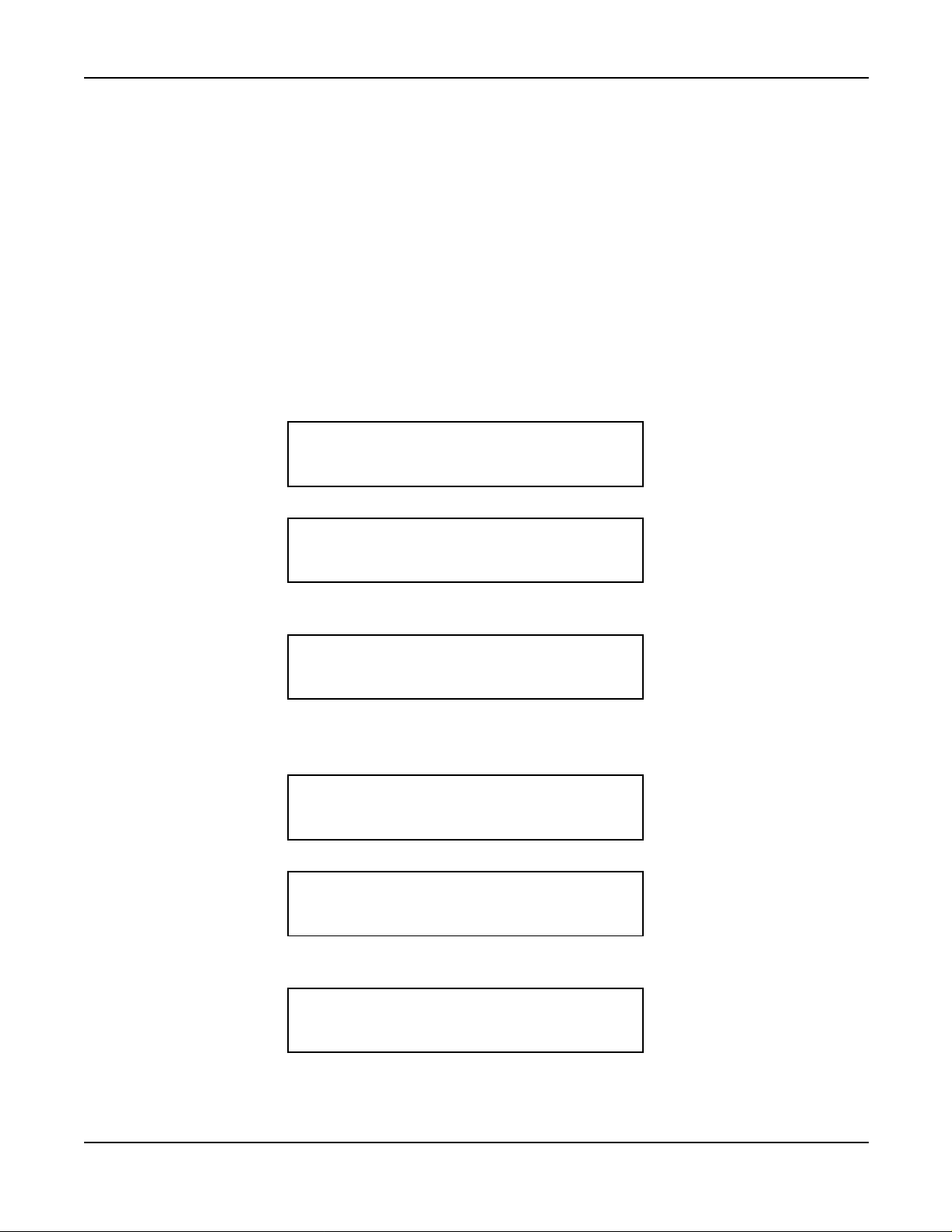
b.) Dial WAKE-UP code. Hear special dial tone. The LCD displays:
c.) Dial desired time of AUTOMATIC WAK E-UP. Hear service set tone. The LC D displays:
term
s.
WAKE UP SET
(Time and Date)
XX:XX SET
(Time and Date)
term
(24-hour time only)
>>>
>>>
d.) Hang up. If the AUTOMATIC WAKE-UP time steady display is available by system data, the
following will display:
XX:XX
(Time and Date)
2. When set and c ancel codes are the same:
a.) Lift the handset or press the SPEAKER key. Receive dial tone.
b.) Dial WAKE-UP code. Hear special dial tone.
WAKE UP SET
(Time and Date)
c.) Dial desired time of AUTOMATIC WAK E-UP. Hear service set tone. The LC D displays:
XX:XX SET
(Time and Date)
d.) Hang up. If the AUTOMATIC WAKE-UP time steady display is available by system data, the
following will display:
XX:XX
(Time and Date)
>>>
>>>
>>>
>>>
NEAX2400 IPX Hotel Features and Specifications
NDA-24310, Issue 1
Page 15
Page 28
A-10D Automatic Wake-Up D
Operating Procedure (cont’d)
To cancel AUTOMATIC WAKE-UP from a Guest Room D
1. With separate set and cancel codes:
a.) Lift the handset or press the SPEAKER key. Receive dial tone.
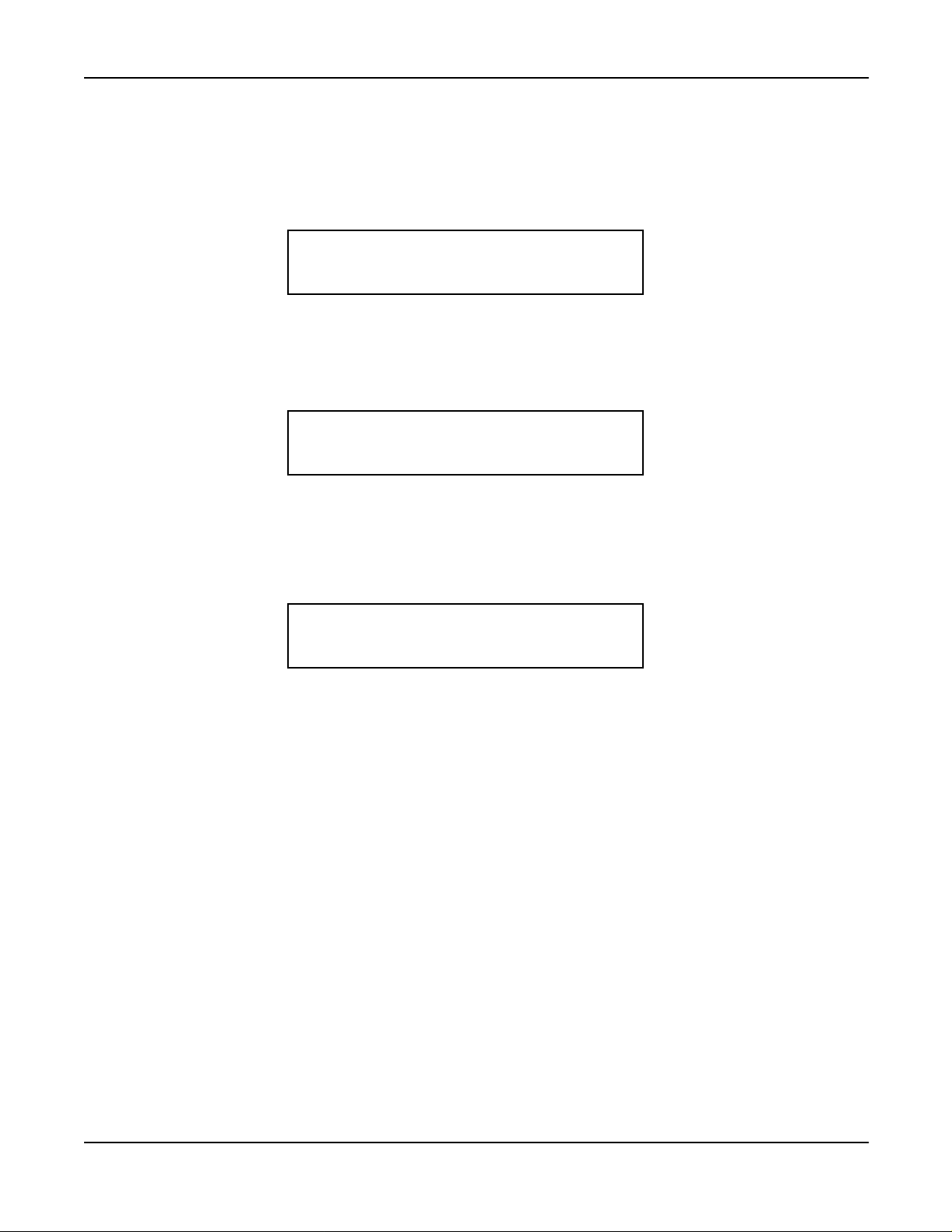
b.) Dial CANCEL AUTOMATIC WAKE-UP code. Hear service set tone. The LCD displays:
WAKE UP CANCEL
(Time and Date)
c.) Hang up.
2. When set and c ancel codes are the same:
a.) Lift the handset or press the SPEAKER key. Receive dial tone.
b.) Dial WAKE-UP code. Hear special dial tone.
c.) Dial the digit “3”. Hear service set tone. The LCD displays:
WAKE UP CANCEL
(Time and Date)
d.) Hang up.
term
(24-hour time only)
term
>>>
>>>
Service Conditions
1. From the Guest room D
2. When AUTOMATIC WAKE-UP is executed, the LCD will display:
3. When the D
term
answers the wake-up call, “WAKE UP” display will remain.
4. The maximum num ber of stations that can se t the same wake-up time can be assigned as one of the
following: 64, 128, 256, 512 stations per LP (Local Partition) depending on system data programming. If
the number of stations reaches the assigned maximum stations, the next attempt to set an AUTOMATIC
WAKE-UP call at the same wake-up time is automatically set 5 minutes earlier than the appointed time.
Note 1: The ability to process this expanded number of c alls is based on traffic and station distribution in the
NEAX2400 IPX.
Note 2: Variable timing can be assigned in system data. The timing must be a multiple of five minutes (such as 5,
10, or 15 minutes) earlier.
5. All AUTOMATIC WAKE-UP times are to be set a t five-minute intervals. F or e xample:
7:50 AM = 0750
7:55 AM = 0755
8:00 AM = 0800
3:00 PM = 1500
3:55 PM = 1555
term
, set AUTOMATIC WAKE-UP using 24-hour time only.
WAKE UP
(Time and Date)
>>>
Page 16 NDA-24310, Issue 1
NEAX2400 IPX Hotel Features and Specifications
Page 29

Automatic Wake-Up D
term
Service Conditions (cont’d)
Note: Wake-Up Time set from a station will be rounded to the nearest multiple of five.
TIME TO BE SET BY KEYPAD OPERATION TIME TO BE SET BY THE NEAX2400 IPX
xx:x1 ~ xx:x4 xx:x0
xx:x6 ~ xx:x9 xx:x5
6. If Wake-Up announcement is used, this feature requires one of the following hardware alternatives:
a.) Central Office Tr unk (COT) or 2W E&M trunk and an announcement machine.
b.) Digital Announcement Trunk (DAT).
7. Thisfeature provides three additional AUTOMATIC WA KE-UP attempts at fixed three-minute intervals.
If the called party is not reached (i.e., no answer, busy, blocked, or locked-out) after a total of four
attempts,the results will automatically print out at the hotel printer. The number of retries for a no-answer
or busy condition is determined by system data, up to a maximum of three retries.
8. Ringing duration for AUTOMATIC WAKE-UP is controlled by SYS1, ASYD, INDEX 139, the Call
Forward, No Answer timer.
9. AUTOMATIC WAKE-UP overrides DO NOT DISTURB [D-11].
Note: For the D
10. AUTOMATIC WAKE-UP messages c an be arranged for headstart operation. Refer to the WAKE-UP
ANNOUNCEMENT - HEADSTART [W-2] feature description for details.
11. If WAKE-UP ANNOUNCEMENT - HEADSTART [W-2] is not required, announcements can be
arranged either as continuous recordings (last party disconnects) or to automatically disconnect after 30
seconds. An engineering tra ffic study is required to determine the number of interface trunks needed to
accommodate each recording channel.
12. When AUTOMATIC WAKE-UP is set from the Administration Station, Front Desk Terminal, or
Console, the LED for AUTOMATIC WAKE-UP on the Guest room D
AUTOMATIC WAKE-UP time steady display is available, the following will display:
term
Series E, this feature is restricted using the DD key of the terminal.
term
illuminates. If the
A-10D
XX:XX
(Time and Date)
>>>
13. If PMS Language Selection is used, AUTOMATIC WAKE-UP announcements can be provided
according to a Guest’s language.
14. If all announcement trunks are busy, music will be provided for AUTOMATIC WAKE-UP. Music is
provided by the NEAX2400 IPX MUSIC ON HOLD [M-1] source.
15. For Guest stations, a confirmation announcement can be provided instead of service set tone for
AUTOMATIC WAKE-UP setting and cancelling operations.
16. AUTOMATIC WAKE-UP entry and result information is reported, as required, to the PMS and
NEAX2400 IPX hotel printer for continuous update.
17. A maximum of six digits can be used for the identification code. Use of an ID code is not mandatory, and
is left to the customer’s discretion.
NEAX2400 IPX Hotel Features and Specifications
NDA-24310, Issue 1
Page 17
Page 30
A-10D Automatic Wake-Up D
term
Service Conditions (cont’d)
18. It is possible to use the same access code for both AUTOMATIC WAKE-UP set and cancel. For example,
*1 may be assigned the AUTOMATIC WAKE-UP set and cancel access code. The NEAX2400 IPX will
recognize *1 and wait for the next digit. If 0, 1, or 2 is dialed, then a time is being set. If the 3 is dialed,
this is a n AUTOMATIC WAKE-UP cancel. For example:
*1 0800 8:00 AM wake-up set
*1 1000 10:00 AM wake-up set
*1 2100 9:00 PM wake-up set
*1 3 wake-up cancel
19. As a system option, once AUTOMATIC WAKE-UP has been set from a Guest station, only that Guest
station is allowed to cancel or change the WAKE-UP service. This option is determined by system data
(Wake-Up Gue st Station Priority Service).
20. These same conditions are applicable to WA KE-UP ANNOUNC EMENT - HEADSTART [W-2].
21. AUTOMATIC WAKE-UP [A-10] and WAKE-UP ANNOUNCEMENT - HEADSTART [W-2]
procedures remain the same.
22. For Distinctive Ringing of AUTOM ATIC WAKE-UP, C.O. Line Incoming Connection is used.
23. When several services are set at the same time, services are displayed according to the following ord er of
priority:
1. AUTOMATIC WAKE-U P - D
term
2. 2ND W AKEUP CALL - SAME GUEST STATION [S-128]
3. MESSAGE WAITING [M-6]
4. DO NO T DISTURB - D
term
5. ROOM CUTOFF [R-9]
24. AUTOMATIC WAKE-UP is not activated f or the Guest station which has been set DO NOT DISTURB
term
-D
by using the DD key of a D
a.) When setting DO NOT DISTURB - D
term
Series E. For example:
term
only:
[A-10D]
[D-11D]
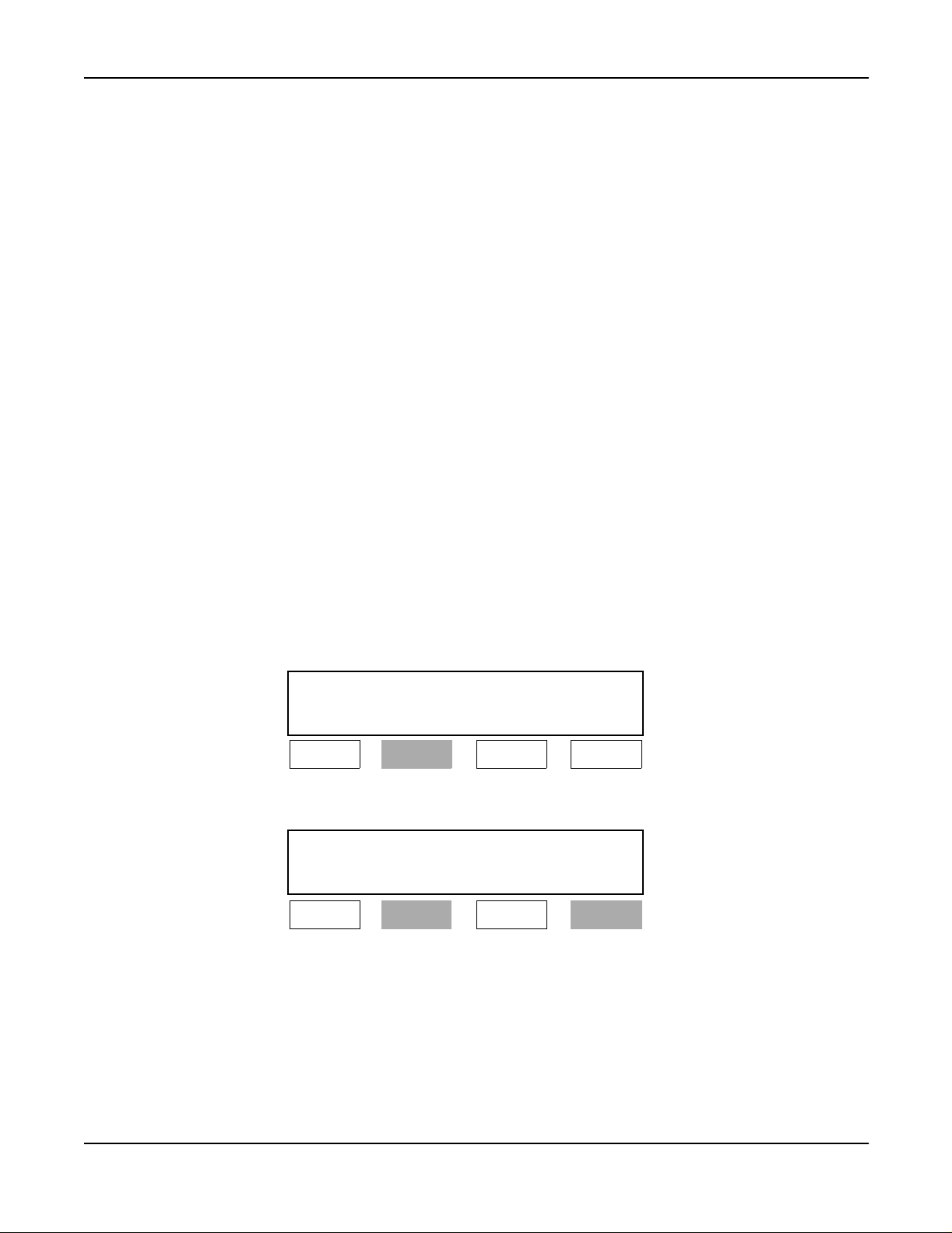
DD
(Time and Date)
Lamp A Lamp B Lamp C Lamp D
Lit
b.) When setting DO NOT DISTURB - D
Wake-UpTime
XX:XX DD
(Time and Date)
Lamp A Lamp B Lamp C Lamp D
Lit Lit
>>>
term
and AUTOM ATIC WAKE-UP - D
>>>
term
:
Page 18 NDA-24310, Issue 1
NEAX2400 IPX Hotel Features and Specifications
Page 31

Service Conditions (cont’d)
c.) When setting DO NOT DISTURB - D
WAITING:
Lamp A Lamp B Lamp C Lamp D
d.) When setting DO NOT DISTURB - D
WAITING and 2ND WAKEUP C ALL - SAME GUEST S TATION (MW lamp illuminates):
Lamp A Lamp B Lamp C Lamp D
In c ase of the MESSAGE WAITING lower display (MW lamp illuminates):
Automatic Wake-Up D
term
, AUTOMATIC WAKE-UP - D
term
Wake-Up Time
XX:XX DD MW
(Time and Date)
>>>
Lit Lit Lit
term
, AUTOMATIC WAKE-UP - D
Wake-UpTime SecondWake-UpTime
XX:XX YY:YY MW
(Time and Date)
>>>
Lit Lit Flashing
term
and MESSAGE
term
, MESSAGE
A-10D
XX:XX YY:YY DD
(Time and Date)
Lamp A Lamp B Lamp C Lamp D
Lit Lit Flashing
Note: On the upper LCD, AUTOMATIC WAKE-UP - D
DO NOT DISTURB - D
term
, and ROOM CUTOFF are displayed in order of priority.
e.) When setting DO NOT DISTURB - D
WAITING, 2ND W AKEUP CALL - SAME GUEST STATION and ROOM CUTOFF (the MW
lamp illuminates):
Wake-UpTimeSecondWake-UpTime
XX:XX YY:YY MW
(Time and Date)
Lamp A Lamp B Lamp C Lamp D
Lit Lit Flashing
f.) When going on-hook at the status of “e” after AUTOMATIC WAK E-UP - D
MW lamp illuminates):
Second Wake-Up Time
YY:YY DD RC MW
(Time and Date)
>>>
term
, 2ND WAKE-UP CALL - SAME GUEST STATION,
term
, AUTOMATIC WAKE-UP - D
term
, MESSAGE
>>>
Lit
term
is activated (the
>>>
Lamp A Lamp B Lamp C Lamp D
Lit Lit Lit
NEAX2400 IPX Hotel Features and Specifications
NDA-24310, Issue 1
Lit
Page 19
Page 32

A-10D Automatic Wake-Up D
term
Service Conditions (cont’d)
g.) When cancelling 2ND WAKEUP CALL - SAME GUEST STATION at the status “e” (the MW
lamp illuminates):
Wake-Up Time
XX:XX DD RC MW
(Time and Date)
>>>
Lamp A Lamp B Lamp C Lamp D
Lit Lit Lit
25. Maximum number of stations per LP that can be set for a single AUTO MATIC WAKE-UP time is
determined by the system da ta.
Lit
Page 20 NDA-24310, Issue 1
NEAX2400 IPX Hotel Features and Specifications
Page 33

Announcement Service A-15
A-15 Announcement Service
General Description
This service feature allows a station user to hear a prerecorded a nnouncement for various services such as:
ALERT SERVICE [A-57]
AUTOMATIC WAKE-UP [A-10]
Confirmation announcement (See AUTOMATIC WAKE-UP) [A-10]
DO NOT DISTURB [D-11] mode setting
GROUP SERVICE THROUGH P MS [G-4]
Hotel information
Intercept announcement when a vac ant level is dialed
Language selection (Property Management System (PMS) option)
Restricted call attempts (ROOM CUTOFF) [R-9]
Tourist group information (tour group schedule & agenda)
Operating Procedure
To access
1. Lift the handset or press the SPEAKER key. Receive dial tone.
2. Dial the associated a nnouncement service access code. The NEAX2400 IPX responds with an
announcement.
3. Listen to the announcement and hang up.
Service Conditions
1. This feature requires one of the following hardware alternatives:
a.) Central Office Tr unk (COT) or 2W E&M trunk and an announcement machine.
b.) Digital Announcement Trunk (DAT).
2. Announcements can be arranged as continuous recordings (last-party disconnect) or to automatically
disconnect after 30 seconds. An engineering traffic study is required to determine the number of interface
trunks needed to accommodate each recording channel.
3. If PMS Language Selection is utilized, ANNOUNCEMENT SERVICE can be provided according to
Guest’s language.
4. The following connections are available:
a.) Multi-connection - many station users can connect to one announcement trunk at the same time.
b.) Single connection - one station user can connect to one announcement trunk at the same time
5. This feature is also available for the Tie Line trunk access to announcement trunk.
6. The NEAX2400 IPX can be programmed to return Ring Back Tone before connection to the
announcement machine is made.
7. When this feature is activated from a Tie Line, the NEAX2400 IPX can be programmed to return answer
supervision to far-end PBX.
8. If PMS Language Selection is used, Announcement Service can be provided according to the Guest’s
language.
9. Checked out Guest Stations cannot use this feature, except for Room Cutoff Announcement.
NEAX2400 IPX Hotel Features and Specifications
NDA-24310, Issue 1
Page 21
Page 34

A-25 Attendant Console With Hotel Functions
A-25 Attendant Console With Hotel Functions
General Description
The NEAX2400 IPX Console provides r egular business call handling and processing capabilities, as well as
hospitality features. The console provides f or the following special hospitality services:
1. Individual keys to set and reset:
AUTOMATIC WAKE-UP [A-10]
MESSAGE WAITING [M-6]
CHECK-IN/CHECKOUT [C-23]
DO NOT DISTURB [D-11]
SECRETARIALSERVICE - GUEST STATION [S-74]
ROOM STATUS [R-10]
MANUAL SWITCHING OF C.O. IN COMING CALL DESTINATION[M-51]
ROOM CUTOFF [R-9]
AUDIT REPORT [A-26] (requires hotel printer)
2. Special keys for incoming call identification:
ADM - Incoming administrative calls
DD - Incoming calls to stations in DO NOT DISTURB [D-11] mode
EMG - OFF HOOK ALARM [O-6] - Emergency calls (option)
GST - Incoming Guest station calls
GST2 - Incoming foreign Guest station calls (option)
HP - HOUSE PHONE/HOT LIN E [H-8]
OT - Overtime calls (option)
WU - Wake-Up calls (option) (Morning Call [MC])
3. Direct key access to frequently called Administration or service stations (i.e., room service, restaurant,
maid, or C.O . number). These numbers are preassigned via the MAT. Ten keys are provided for this
feature.
4. The console provides the following displays:
Calendar (date and time)
Call Waiting (number of calls)
Class of Service
Name Display - System (for Administration stations)
Room Status:
- AUTOMATIC WAKE-UP [A-10]
- DO NOT DISTURB [D-11]
- GUEST NAME DISPLAY THROUGH PMS [G-5]
- Language (PMS Option)
- MESSAGE WAITING [M-6]
- Optional data display (Refer to Service Condition 3.)
- Room class
- ROOM CUTOFF [R-9]
- R oom occupied
- S tation number
- VIP (PMS option)
Station/Trunk
Tenant Number
Page 22 NDA-24310, Issue 1
NEAX2400 IPX Hotel Features and Specifications
Page 35

Attendant Console With Hotel Functions A-25
General Description (cont’d)
Note: If theDesk Console is used instead of theNEAX2400 IPX Hotel Attendant Console, the basic keyallocations
are different from the previous ones. The following illustration shows the Desk Console key positions and
indications used in Hotel Systems. The operating procedures for each service are the same as the
NEAX2400 IPX Hotel Attendant C onsole.
LCD
TRKSL SVC SC
HWS BV
Alarm Position Available
HWC HP DD GST OT ICPT
L 6
L 5
L 4
L 3
L 2
L 1
1
2
ABC3DEF
6
5
4
MNO
JKL
GHI
9
8
7
WXYZ
TUV
PQRS
0
∗
#
TFRecallNANSADMBusyTIELDN
SRC
Release Hold
Cancel
Talk
Position Busy
PAGE REC
Start Mute
DEST
Answer
Night
Night
Position Busy
DDO
WUS
DDS RCS MWS
WUR DDR RCR MWR STS
MR CLR
Enter
Clear
Exit
Hotel Function key
TG6
TG1
TG2
TG7
TG3
TG8
TG9
TG4
TG10TG5
DSS key
The different key indications of the NEAX2400 IPX Attendant Console and the Desk Console are shown below:
HOTEL ATTENDANT
CONSOLE DESK CONSOLE
WKUP (Set)
WKUP (Reset)
DD (Set)
DD (Reset)
RC (Set)
RC (Reset)
MW (Set)
MW (Reset)
WUS
WUR
DDS
DDR
RCS
RCR
MWS
MWR
HOTEL ATTENDANT
CONSOLE DESK CONSOLE
TKSL
TRKSL
SRLC
DD OVER
PG
RCL
OT
SC
DDO
PAGE
Recall
OT
Figure 1 Key Allocations of Desk Console
Operating Procedure
Refer to the NEAX2400 IPX How to Operate Attendant Console.
Service Conditions
1. Distance limitation between the NEAX2400 IPX and the console: up to 1000 feet (304 meters) using 25pair, 24 AWG cable.
2. Maximum of four c onsoles per PIM.
3. A three-character and a five-character display c an be used in conjunction with PMS to display additional
Guest information instead of language and room class. F or e xample, company name, complementary
code, etc. may be displayed.
4. The OAI name of the Administration station is displayed on the character display (Guest name display
area) when Name Display service via OAI is available in the NEAX2400 IPX. When there is no name
assigned for the Adm inistration station, “ADM STATION” is displayed.
NEAX2400 IPX Hotel Features and Specifications
NDA-24310, Issue 1
Page 23
Page 36

A-26 A udit Reports
A-26 Audit Rep orts
General Description
The NEAX2400 IPX provides AUDIT REPORT printout of all rooms assigned specific R oom Status conditions.
For example, an AUDIT of all stations in DO NOT DISTURB [D-11] mode m ay be ordered. These REPORTS are
generated by key operation and function codes entered from the Hotel Console. AUDIT REPORTS available from
the printer are as follows:
Table 7 Audit Re port
FUNCTION
CODE DEFINITION
0 All Status All Status
1
2 Cleaned
3 Readytosell
Maid Status
4 Out of Service
5 Repair Needed
6 Vacant
7
8 MESSAGE WAITING set [M-6]
9 AUTOMATIC WAKE-UP [A-10] (Room & T ime)
Room Condition
10 Vip R oom (see service condition, PMS option)
11 DO NOT DISTURB [D-11]
12 ROOM CUTOFF [R-9]
*
21 Room Class 1
To be Cleaned
Occupied
All Class Audit
PRINTOUT INFORMATION
22 Room Class 2
23 Room Class 3
24 Room Class 4
25 Room Class 5
26 Room Class 6
27 Room Class 7
28 Room Class 8
29 Room Class 9
20 Room Class 10
2* Room Class 11
2# Room Class 12
Page 24 NDA-24310, Issue 1
Room Class
NEAX2400 IPX Hotel Features and Specifications
Page 37

Audit Reports A-26
Operating Procedure
To order AUDIT RE PORT S printouts from the Console or F ront D esk Terminal
1. Press the AUD key. The associated lamp illuminates
2. Press the STS key. Dial the desired function code.
3. The function code is displayed. Press the ENTER key.
4. All displayed information is cleared and lamps are extinguished. Printout begins.
Service Conditions
1. VIP classification must be entered via PMS.
2. Room classifications are assigned via the MAT.
3. Guest na me and optional data (La nguage, etc.) are displayed on the Console, but are not included in the
printout.
4. Hotel printer is necessary for this service feature.
5. Only one audit may be run at a time.
6. Status information is automatically printed out w hen the following services are performed:
• MAID S TATUS [M22] (from Guest room only).
• AUTOMATIC WAKE-UP [A-10] (unanswered, blocked calls).
NEAX2400 IPX Hotel Features and Specifications
NDA-24310, Issue 1
Page 25
Page 38

A-48 Automatic Message Waiting Lamp Off
A-48 Automatic Message Waiting Lamp Off
General Description
This feature provides for Guest station MESSAGE WAITING [M-6] lamps to automatically turn off after Guests
have called pr edetermined Administration Stations (i.e. Message Center) to retrieve messages.
Operating Procedure
When a Guest calls the Administration Station to retrieve a message, the MESSAGE WAITING [M-6] lamp on the
associated Guest telephone is automatically extinguished and the M ESSAGE WAITING [M-6] data is cleared.
Service Conditions
1. This service is only available when the MESSAGE WAITING [M-6] has been set from:
a.) Front Desk Terminal (Model 90 or 120 P MS).
b.) Front Desk Terminal or Console (Model 60 PMS).
2. This feature is not available when calling the Console.
3. Message Waiting lamps set by Message Center Interface will not be cancelled by AUTOMATIC
MESSAGE WAITING LAMP OFF [A-48].
4. Refer to MESSAGE WAITING [M-6] for more information.
Page 26 NDA-24310, Issue 1
NEAX2400 IPX Hotel Features and Specifications
Page 39

Alert Service A-57
A-57 Alert Service
General Description
In an emergency situation, the Console or Special Administration Station may initiate the ALERT SERVICE. All
Guest stations and Special Administration Stations are c alled, using a distinctive ringing pattern, and c onnected to
an emergency announcement.
term
At this time, if D
s are used for Guest stations, the D
Operating Procedure
To set ALERT SERVICE from Console
1. Press the LOOP key.
2. Dial the access code for A lert Service Setting.
a.) Receive service set tone.
b.) All the Guest Stations and all the Special Administration are rung.
3. Press the RELEASE ke y.
To cancel ALERT SERVICE fro m Console
1. Press the LOOP key.
2. Dial the access code for Alert Service Cancel. Receive service set tone.
3. Press the RELEASE ke y.
To set ALERT SERVICE from Special Administration Station
1. Lift the handset. Receive dial tone.
2. Dial the access code for A lert Service Setting.
a.) Receive service set tone.
b.) All the Guest Station and all the Special Administration Station are rung.
3. Replace the handset.
To cancel ALERT SERVICE from Special Admi nistrati on Station
1. Lift the handset. Receive dial tone.
2. Dial the access code for Alert Service Cancel. Receive service set tone.
3. Replace the handset.
To answer
1. The Stations rung by the Alert Service lifts the handset. Announcement is heard from the Announcement
Machine. Note
2. Replace the handset.
Note: On answering,thestationisautomaticallyconnectedtoan announcementmachine. If Language service has
been specified by PM S, the Guest will receive the announcement in their own language.
term
LCDs will indicate emergency.
Service Conditions
1. A Guest station is called every 2 seconds, to a maximum of 24 stations per Module Group ringing
simultaneously. The stations are called in ascending order, based on Line Equipment Number (LEN) per
Module Group (MG). After all stations in a Port Interface Module (PIM) have been called, the pr ocess is
repeated in an attempt to r each stations that did not answer, we re busy, or were blocked. Unreachable
stations will be tried three times by the NEAX2400 IPX.
NEAX2400 IPX Hotel Features and Specifications
NDA-24310, Issue 1
Page 27
Page 40

A-57 Alert Service
Service Conditions (cont’d)
2. Stations will be retried if the Guest does not answer, the line is busy, or the line is in LINE LOCKOUT
[L-3]. Stations in the Ma ke Busy condition are not called. The unanswered Guest information is printed
out from the hotel printer. Note that the information is also printed out when the called station is a Guest
Room - D
3. ALERT SERVICE overrides DO NOT DISTURB [D-11].
4. Special Administration Stations are also called.
5. The ringing pattern used with ALERT SERVICE is shown below. This pattern may not be changed.
term
.
ON
OFF
0.2 sec
0.4 sec0.4 sec0.4 sec
1 sec 0.2 sec
0.4 sec
6. If a printout of responses (i.e., answered, blocked, busy) is required, the hotel printer must support a
minimum of 220 characters per second (CPS).
7. Whenannouncementtrunksfor ALERT SERVICE in different languages are provided, the Guest receives
the announcement in his/her own language. In this case, the Guests are connected to the announcement
trunk in multiple connection, and if the Gue st does not go on hook after hearing the announcement, the
call is disconnected automatically after 30 seconds.
8. While Guest stations are ringing, the LCDs on the Guest room D
term
s (if used) will display:
EMERGENCY CALL
(Time and Date)
>>>
Page 28 NDA-24310, Issue 1
NEAX2400 IPX Hotel Features and Specifications
Page 41

Automatic Wake-up - Hot el Attendant A-58
A-58 Automatic Wake-up - Hotel Attendant
General Description
When AUTOMATIC WAKE-UP [A-10] is set to the Guest station with VIP status a nd it is time for the Guest to be
awakened,thecallwillringtheConsole.When answered,the callis extendedto the Guest. The Guest will be greeted
by the attendant rather than a recorded a nnouncement.
Operating Procedure
To operate from the Console
1. On the Hotel Console, the WU (Wake-Up) lamp flashes and the bell rings at preset time.
2. Pressthe WU key or ANSWER key.
of C onsole. Note 2
3. Pressthe START key. Receive Ring Back Tone. The Station is rung. If a D
the LC D will display as follows:
Note 1 The status of Guest station to be called appears on the display
term
is used for a Guest station,
WAKE UP
(Time and Date)
>>>
4. Guest Station lifts the handset. Hotel Attendant informs Wake-Up time. If a D
term
is used for a Guest
station, “WAKE UP” display goes out.
5. Press the RELEASE ke y.
Note 1: If the Guest station concerned goes off hook while a call termination is being indicated at the WU key, this
is processed as an answer to AUTOMATIC WAKE-UP [A-27], and AUT OMATIC WAKE-UP—HOTEL
ATTENDANT ASSISTANCE is cancelled.
Note 2: If the Guest station concerned goes off-hook after the Hotel Attendant presses the WU or ANSWER key,
but before pressing of the START key, the Hotel Attendant and the Guest station can communicate.
Note 3: VIP status is set via PMS at the time of CHECK-IN/CHECKOUT [C-23] or when room data is changed.
Service Conditions
1. The Service Conditions for setting and resetting AUTOMATIC WAKE-UP [A-10] also apply to
AUTOMATIC WAKE-UP - HOTEL ATTENDANT.
2. ATTENDANT CONSOLE WITH HOSPITALITY FUNCTIONS [A-47] and AUTOM ATIC WAKE-UP
[A-10] must be provided.
3. If Wake-Up is set to a primary station of a SUITE ROOM SERVICE [S-75], the status is displayed on the
Direct Station Selection (DSS) keys. The Attendant may initiate ringing to all the phones in a suite by
pressing the START key, or to a specific phone by pressing the corresponding DSS key.
4. If the Guest station goes off-hook after the Attendant presses the WKUP ke y, but before the Attendant
presses the START key, the Guest and Attendant will be c onnected.
5. The NEAX2400 IPX reports the Wake-Up call as “called” at the time it rings in at the WKUP key.
6. An incoming Wake-Up call to the Console that is not answered will not time out. The NEAX2400 IPX
will not divert unanswered Wa ke-Up calls to AUTOMATIC WAKE-UP [A-10]. AUTOMATIC WAKEUP [A-10], AUTOMATIC WAKE-UP - HOTEL ATTENDANT [A-58], and VIP Wake-Up are mutually
exclusive.
7. System audit shows “Attendant-called” when the Console rings for a Wake-Up c all, and shows
“Attendant-answered” when the Attendant answers the call. Wake-up result is sent to PMS.
NEAX2400 IPX Hotel Features and Specifications
NDA-24310, Issue 1
Page 29
Page 42

A-58 Automatic Wa ke-up - Hot el Attendant
Service Conditions (cont’d)
8. The console displays “ATC”, and no other result is sent to PMS when the Attendant answers the call.
9. Setting and cancelling WAKE-UP services are restricted from administration stations, the Console, the
PMS Terminal, a Front Desk Terminal, or predeterminedSpecialAdministrationStationif the feature was
set by the Guest room station. These restrictions are programmable with the system data.
10. AUTOMATIC WAKE-UP [A-10] and WAKE-UP ANNOUNCEMENT - HEADSTART [W-2]
execution remain the same.
11. VIP Wake-Up Variation: Guest stations are given the VIP status via the PMS computer. When
AUTOMATIC WAKE-UP [A-10] is set to the VIP Guest station and it is time for the Guest to be
awakened, the call will ring the Console. When answered, the call is extended by the Attendant to the
Guest. The Guest will be greeted by the attendant rather than a recorded announcement.
a.) An incoming VIP Wake-Up call to the Console will ring up to three minutes. If the Attendant
does not answer after three minutes, the NEAX2400 IPX will divert the VIP W a ke-Up to
AUTOMATIC WAKE-UP [A-10]. The service conditions of AUTOMATIC WAKE-UP [A-10]
will apply.
b.) VIP Wake-up processing can be cancelled by the Console.
c.) When the VIP Wake-Up is attempted for a Guest station, a station check at the Console for that
station will display CLD while the console rings. The Console displays ANSWER when the
Attendant is called.
d.) If the attendant detects an overload of incoming Hotel Attendant Assistance Wake-Up calls,
processing of the calls can be altered. The attendant seizes a loop and dials the Hotel Attendant
Assistance Wake-up cancel code. The calls will be handled as AUTOMATIC WAKE-UP [A-10]
calls. This ensures that the Guests are awakened in a timely manner. When the overload is
determined to be over, the Attendant seizes an idle loop and dials the Hotel Attendant Assistance
Wake-up reactivate code.
12. Automatic W ake-Up hotel attendant assistance overrides Do Not Disturb.
Page 30 NDA-24310, Issue 1
NEAX2400 IPX Hotel Features and Specifications
Page 43

Automatic Multiple Attendant Recall A-73
A-73 Automatic Multiple Attendant Recall
General Description
This feature is a variation of the Autom atic Recall feature of the NEAX2400 IPX. Whe n the Attendant answers an
incoming trunk call, dials the station, and presses the RELEASE key, the automatic-recall timer is activated. The
dialed station rings, but if it is unanswered within the c ustomer-defined recall time, the call is directed to all active
Attendants a s an incoming call on the NANS (no answer) I CI key - the dialed station stops ringing at this point. If
there is no available Attendant, the call is directed to the Attendant who originally handled the call, and the dialed
station begins ringing again. It continues ringing until the incoming trunk is released.
Operating Procedure
1. The Attendant presses the incoming trunk call identification key or the ANSWER key when the call
waiting lamp is lit.
2. The Attendant dials the station number, then presses the RELEASE key.
a.) The Automatic Recall timer is activated.
b.) The caller hears ringback tone while the called station rings, and the call remains in the Attendant
loop (i.e., the Attendant that answered the c all can retrieve the c all before the station answers or
before the recall time elapses).
3. If the station does not answer within the recall time, the NEAX2400 IPX releases the station. Any
Attendantcan presstheNANS key and talk to the caller. The call rings on all active Attendantsas a NANS
(no answer) call, and can be answered by any of the Attendants. Note
4. If CALLED NUMBER DISPLAY - ATTENDA NT [C-59] is a ctivated:
a.) The unanswered station number is displayed as the destination, and the DEST lamp lights.
5. If the Attendant presses the SRC key:
b.) The calling trunk number is displayed and the SRC lamp lights; the DEST lamp goes off.
Note: If the ATTENDANT LOOP RELEASE [A-6] is activated, the recall timer is fixed at 30 seconds.
Service Conditions
1. This feature is not available on a tenant basis, only on a system basis.
2. This feature only works on incoming trunk calls. Internal calls recall to the original Attendant.
3. This feature only applies when the automatic-recall timer elapses while timing a call to a ringing,
unanswered station. It does not apply to stations with ATTENDANT CAMP-ON [A-1] or C ALL HOLD
[C-6].
4. AUTOMATIC MULTIPLE ATTENDANT RECALL can be used in conjunction with ATTENDANT
LOOP RELEASE [A-6]. When the programmable timer runs out, the call is directed to all attendants
without recalling on a specific Attendant loop.
5. This feature is not available for INCOMING C.O. CALLS TO TIE LINE C ONNECTIONS [I-3].
6. This feature applies to both Guest and administration stations.
7. ATT peg count is increased by one when the call is redirected to the attendants.
8. A call record is not sent to SMDR until the call is answered by one of the attendants.
9. CALL FORWAR DING - DON'T ANSWER [C-3] supersedes this feature.
10. This feature can be used in conjunction with CALLED NUMBER DISPLAY - ATTENDANT [C-59]. I f
CALLED NUMBER DI SPLAY - ATTENDANT [C-59] is activated, the c alled station number is
displayed on the console when the Attendant answers. ( The called number is displayed not only by
AUTOMATIC MULTIPLE ATTENDANT RECALL, but also by call forwarding to Attendant.)
NEAX2400 IPX Hotel Features and Specifications
NDA-24310, Issue 1
Page 31
Page 44

A-73 Automatic Multiple Attendant Recall
Service Conditions (cont’d)
11. The “Called Number” displayed is the number of the station that is ringing when the attendant presses the
RELEASE key. If the c all has been forwarded, this number is not the same as the dialed number.
12. Automatic Multiple Attendant Recall is not available for calls transferred to stations over CCIS.
Page 32 NDA-24310, Issue 1
NEAX2400 IPX Hotel Features and Specifications
Page 45

Answering Camp-On/Call Hold Calls By S witchhook Flash A-74
A-74 Answering Camp-On/Call Hold Calls By
Switchhook Flash
General Description
This feature allows a busy Guest station to answer a CAMP-ON or CALL HOLD call automatically by using switch
hook flash.
Operating Procedure
To answer a CAMP-ON call
1. The Attendant executes ATTENDANT CAMP-ON WITH TONE I NDICATION [A-1]. A busy Guest
station user hears a camp-on tone indication.
2. If the camped-on station becomes idle:
a.) It is automatically rung and connected to the waiting trunk when the user answers. An alternative
is for camped on station to perform a switch hook flash.
3. When ANSWERING CAMP-ON/CALL HOLD CALLS BY SWITCH HOOK FLASH has been enabled
and the camped-on station performs a switch hook flash:
a.) The call in progress is placed in a CALL HOLD [C-6] state and the camped-on station is
connected to the CAMP-ON call. The station can then al ternate between the two parties by
repeating the switch hook flash.
4. When ANSWERING CAMP-ON/CALL HOLD C ALLS BY SWITCH HOOK FLASH has been
restricted:
a.) CALL HOLD [C-6] can be used to answer the CAMP-ON call.
To answer a CALL HOLD call
1. A station uses CALL HOLD [C-6]. The call is placed on hold.
2. The station initiates another call.
3. When the station becomes idle:
a.) It is automatically rung and the user is connected to the call on hold upon answer. The station
may also perform a switch hook flash to reconnect with the held call.
4. When this feature is enabled and the station performs a switch hook f lash:
a.) The call in progress is automatically placed in a CALL HOLD [C-6] state and the original call is
reconnected. The station can then alternate between the two parties by repeating the switch hook
flash.
5. When this feature is restricted:
a.) CALL HOLD [C-6] can be used to place the second call on hold and return to the original call.
Service Conditions
1. This feature may be used to answer CAMP-ON calls by Administration Stations when FLASH BUTTON
2. This feature m ay be used to answer CALL HOLD calls by Administration Stations when FLASH
3. The operating procedure for CALL HOLD [C-6] is replaced by this feature when SYS1, INDEX 177, Bit
NEAX2400 IPX Hotel Features and Specifications
NDA-24310, Issue 1
term
-D
way for Adm inistration Stations to answer CAMP-ON calls.
BUTTON - D
alternative.
6 is enabled.
[F-3D]has been allowed. However, CALL WAITING - ANSWER - D
term
[F-3D] has been allowed. However, CALL HOLD - D
term
[C-27D]is the preferred
term
[C-6D] may be used as an
Page 33
Page 46

A-74 Ans wering Camp-On/Call Hold Calls By Switchhook Flash
Service Conditions (cont’d)
4. The operating procedure for CALL HOLD - D
term
[C-6D] using FLASH BUTTON - D
replaced by this feature when e nabled in system data.
5. The function of the TRANSFER key on the D
term
does not change when this feature is enabled.
6. The limitations for ATTENDANT CAMP-ON WITH TONE INDICATION [A-1] and for CALL HOLD
[C-6] apply to this feature.
term
[F-3D] is
Page 34 NDA-24310, Issue 1
NEAX2400 IPX Hotel Features and Specifications
Page 47

Automated Guest Station Voice Mail Retrieval A-75
A-75 Automated Guest Station Voice Mail Retrieval
General Description
AUTOMATED GUEST STATION VOICE MAIL RETRIEVAL (VMR) is a feature that m akes it easy for Guest
stationsto retrieve voice mail. Guest stations dial a Voice Mail Re trieval (VMR) access code and a station password
for immediate message retrieval. The feature is customer-programmable to allow it to conform to the needs of any
voice m ail system.
Operating Procedure
The voice mail facility m ust be set up as an administrative station.
1. The Guest sees that the Message Waiting Lamp on the Guest station is lit.
2. The Guest lifts the handset and dials the VMR access code. The Voice Mail System (VMS) answers, and
prompts the Guest for his password (if required).
3. The Guest enters the password. The VMS plays the messages.
Note: A Guest station can be provided with normal voice mail operating procedures or AUTOMATED GUEST
STATION VOICE MAIL RETRIEVAL at the discretion of the NEAX2400 IPX operator.
Service Conditions
1. This feature is not available whe n the Guest station has a party on hold. If a party is on hold, normal
operating procedures for voice mail access will be required. This procedure usually requires the dialing of
the station number and password, but r ead the appropriate voice mail manual for c omplete instructions.
2. Normal operating procedure should be used by the Console and the Administration Stations.
3. Ifa Guest does not listen to the messages before checking out, the messages must be r emoved by the Voice
Mail administrative terminal.
4. Access to voice mail is established by dialing a VMR access c ode, and internal dialing by the P BX of a
function c ode (limited to 2 digits plus a pause) and the station number (maximum of 5 digits). The order
will be dependent on the voice mail system.
NEAX2400 IPX Hotel Features and Specifications
NDA-24310, Issue 1
Page 35
Page 48

B-26 Busy Status - Hotel Attendant
B-26 Busy Status - Hotel Attendant
General Description
When the Hotel Attendant calls a Guest station that is busy, BUSY STATUS DISPLAY - HOTEL ATTENDANT
causes the current status of the called Guest station to display in detail on the console LCD.
The f ollowing figures show the LCD displays f or each status.
1. When the called station receives dial tone (off-hook status):
STA BUSY
XXXX→BUSY
2. When the called station is in m ake busy status:
STA BUSY
XXXX→MAKE BUSY
3. When the called station is in LIN E LOCK OUT [L-3] status:
STA BUSY
XXXX→LOCK OUT
4. When the called station is dialing:
STA BUSY
XXXX→DIALING
5. When the called station is being accessed from another station:
STA BUSY
XXXX→RINGING
6. When the called station is talking to the Administration Station:
STA BUSY
XXXX→ADM:XXXX
7. When the called station is talking to another Guest Station:
STA BUSY
XXXX→GST:XXXX
8. When the called station is engaged in a Central Office (CO) line call and when C entral Of fice code (1-4
digits) is assigned:
STA BUSY
XXXX→COC:X
Page 36 NDA-24310, Issue 1
NEAX2400 IPX Hotel Features and Specifications
Page 49

Busy Status - Hotel Attendant B-26
General Description (cont’d)
9. When the called station is engaged in a CO line call and when Central Office code is not a ssigned:
STA BUSY
XXXX→RT:XX
10. When the called station is engaged in a call with a Hotel Attendant, and specified Attendant Number (1 to
6 digits) is assigned:
STA BUSY
XXXX→ATT:XXX
11. When the called station is engaged in call with a Hotel Attendant, and Specified Attendant Number is not
assigned:
STA BUSY
XXXX→ATN:X
12. For other status conditions:
STA BUSY
XXXX→BUSY
Operating Procedure
To operate from the Hotel Console
1. The attendant dials a station number individually, or while holding a station/trunk. Receives busy tone or
reorder tone according to the status of the called station.
2. The attendant presses the STS key. The current status of the called station displays on the console LCD.
3. The attendant presses the EXT key. The console LCD returns to the previous display.
4. From the status described in either step 2 or 3, the attendant presses the CANCL key.
a.) The Attendant is connected to the original party.
b.) The console LCD returns to the initial display.
Service Conditions
1. BUSY STATUS DISPLAY - HOTEL ATTENDANT is available only for the Hotel Console.
2. This feature is available only when the called party is a Guest station.
NEAX2400 IPX Hotel Features and Specifications
NDA-24310, Issue 1
Page 37
Page 50

C-19 Calendar Display
C-19 Calendar Display
General Description
A digital display indicating month, day, hour, and minute is provided on the Console.
Operating Procedure
Hour and minute information is c onstantly displayed. Month and day information is displayed only while key
operations pertaining to hospitality services are not being per formed.
Service Conditions
1. Hour and minute display - (constant).
Note: The Attendant Console clock reads 00:00 AM at midnight and 00:00 PM at noon. The Desk Console c lock
reads 00:00 AM at midnight and 12:00 PM at noon.
2. Month and day a re displayed as shown below.
a.) On the Attendant Console:
MONTH XX DAY DAY OF W EEK
Name
b.) On the Desk Console:
HH:MM AM/PM MONTH XX DAY DAY OF WEEK
Name
3. The time indication can be corrected by use of the MAT command ATIM.
Page 38 NDA-24310, Issue 1
NEAX2400 IPX Hotel Features and Specifications
Page 51

Check-In/Checkout C-23
C-23 Check-In/Checkout
General Description
This service manages Vacant/Occupied status of each Guest room, and automatically restrict/cancel the restric tion
forsuch servicesas C.O. outgoing call, Automatic Wake-Up, etc.according to the present status of each Guest room.
When CHECK-IN/CHECKOUT service is activated from the PMS terminal, the Console, or the Front Desk
Terminal, the following operations occur:
• CHECK-IN: The services available at the Guest station are dependent upon the Guest station Class of
Service (as defined by the CLASS OF SERVICE - I NDIVIDUAL [C-15]).
• CHECKOUT: DO NOT DISTURB [D-11] - Reset
ROOM CUTOFF [R-9] - Set
MESSAGE WAITING [M-6] - Reset
AUTOMATIC WAKE-UP [A-10] - Clear
GUEST NAME DISPLAY D
GROUP SERVICE through PMS [G-4] - Reset
Note: Features may be cleared from the PMS terminal depending on data assignment when PMS Model 60 is
used. All data is cleared when the Console is used. Features may be cleared from the PMS terminal
depending on code sent to the NEAX2400 IPX when PMS Model 90 or 120 is used.
term
[G-6D] - Clear
Operating Procedure
Check-In from the Console or Front Desk Terminal
1. Press the CHK IN key. The associated lamp illuminates.
2. Dial the Guest room number. The Guest room number is displayed.
3. Press the ENTER key. The lamp flashes to confirm Check-In.
4. Press the EXIT key. The lamp and Guest room number are extinguished.
Checkout from the Console or Front Desk Terminal
1. Press the CHK OUT key. The associated lamp illuminates.
2. Dial the Guest room number. The Guest room number is displayed.
3. Press the ENTER key. The lamp flashes to confirm Checkout.
4. Press the EXIT key. The lamp and Guest room number are extinguished.
Note 1: If an error is made in the course of key operations, press the CLEAR key and continue from Step 2 (station
dialing).
Note 2: When performingCHECK-IN/CHECKOUT for two or more Guests at the same time, follow Steps 1 through
3 for the first Guest. Follow Steps 2 and Step 3 only for the remaining Guests, then Step 4 to exit from the
CHECK-IN/CHECKOUT mode.
Service Conditions
1. When the PMS feature is in operation, the CHK IN/CHK OUT key does not function from the Console.
CHECK-IN/CHECKOUT is activated by the PMS computer.
2. The CHK IN/CHK OU T key at the Front Desk Terminal is always operational. The Front Desk Terminal
CHK IN/CHK OUT key can be used to unrestrict or restrict the Guest's phones prior to Check-In/Out from
the P MS terminals as a temporary CHECK-IN/OUT when the PMS terminals are overloaded.
NEAX2400 IPX Hotel Features and Specifications
NDA-24310, Issue 1
Page 39
Page 52

C-32 Calling Station Num ber Display
C-32 Calling Station Number Display
General Description
This feature provides hospitality service stations (r estaurant, valet, room service, etc.) and Guest stations with an
LCD display of incoming calling number (Guest, Adm inistration, OG, or IC trunk). This display flashes while the
call is r inging, then appears steadily when the call is answered. D
Operating Procedure
1. Incoming call to the prime line:
a.) Automatically activates the CALLING N UMBER DISPLAY.
2. If a call terminates to another line appearing on the D
a.) Press the ringing line button. The hospitality service station LCD will display:
(Time and Date)
-OR-
(Time and Date)
term
may be used for service stations.
term
:
RMO XXXX
>>>
RMS XXXX
>>>
(Time and Date)
HH:MM DDD
(Time and Date)
HH:MM indicates lapsed time, DDD indicates trunk type (1-3 digits)
The Guest room station LC D will display:
(Time and Date)
(Time and Date)
(Time and Date)
-OR-
ADM XXXX
>>>
-OR-
>>>
ADM XXXX
>>>
-OR-
OPR
>>>
-OR-
DDD X
>>>
Page 40 NDA-24310, Issue 1
NEAX2400 IPX Hotel Features and Specifications
Page 53

Operating Procedure (cont’d)
b.) Lift handset and answer the call. The display stops flashing.
Calling Station Num ber Display C-32
HH:MM FX X
(Time and Date)
>>>
HH:MM WATS X
(Time and Date)
>>>
HH:MM TIE X
(Time and Date)
>>>
HH:MM CCSA X
(Time and Date)
>>>
Service Conditions
1. When a c all terminates to a line other than the prime line, the LCD displays the incoming station as
determined by LINE PRESELECTION - D
term
2. LINE PRESELECTION - D
returns to TIME DISPLAY - D
[L-9D] is governed by a timer. Af ter the timer times out, the display
term
[T-18D].
3. The display will show either RMO (Room Out) and the station number, or RMS (Room Stay) and the
station number when connected to a Guest station, depending on the data sent from PMS. The display will
show ADM (Administration) when connected to any station other than a Guest station.
4. The RMO, RMS, and ADM displays do not appear when calling between nodes of CCIS network.
term
[L-9D].
NEAX2400 IPX Hotel Features and Specifications
NDA-24310, Issue 1
Page 41
Page 54

C-71 Ca lled Number Display - Hotel Attendant Console
C-71 Called Number Display - Hotel Attendant
Console
General Description
If a call is transferred to the Console as a result of the following features:
DO NOT DISTURB [D-11]
CALL FORWARDING - ALL CALLS [C-5]
CALL FORWARDING - BUSY LINE [C-2]
CALL FORWARDING - DON'T ANSWER [C-3]
CALL FORWARDING - INTERCEPT/ANNOUNCEMENT [C-25]
Information pertaining to that station is displayed on the Console. The LCD displays on the Attendant Console and
Desk C onsole are illustrated below.
• The LCD on the Attendant Console displays as shown below:
TN CLS
STATION/TRUNK NO . ROOM INFO RMATION
XX
LO RSC
Calling Station Number Called Station Number and Called
• The LCD on the Desk Console displays as shown below:
XXXX
NAME
XXXX A0700
STATION WK TIME LANG.
DD
RC VIP
Station Room Status Information
MW OCPD
:
STAY
NAME STAY
SRC TN:X CLS:X XXXX A0700
No. XXXX
DD RCO MW OCPD
Figure2 Display Area of Attendant Console and Desk Console
Operating Procedure
1. Theattendantanswers a n incomingcall.The DEST lamp lights, and the called station number is displayed.
2. The attendant presses the SRC key. The DEST lamp goes off, and the SRC lamp lights. Either the calling
party's station number or the route/trunk number is displayed.
Service Conditions
1. This feature is effective when a station-to-station call or a DID call has been routed to an Console as a
result of DO NOT DISTURB [D-11], CALL FORWARDING - ALL CALLS [C-5], CALL
FORWARDING - BUSY LINE [ C-2], CALL FORWARDING - DON'T ANSWER [C-3], or CALL
FORWARDING - INTERCEPT/ANNOUNCEMENT [C-25], and is answered by the Attendant.
Page 42 NDA-24310, Issue 1
NEAX2400 IPX Hotel Features and Specifications
Page 55

Called Number Display - Hotel Attendant Console C-71
Service Conditions (cont’d)
2. If the Attendant presses the SRC key while the called station number is displayed, the display changes to
the num ber of the calling pa rty. The called station number cannot be displayed again.
3. While the called station number is displayed, the Attendant can transfer the c all to a desired station by
keying the destination number on the keypad. In this case, the called station number of that call cannot be
displayed again.
4. While the called station number is displayed, the Attendant can place the call on hold by pressing the
HOLD key.
5. While the called station number is displayed, the Attendant can set CALL PARK [C-29] service. The
called station number cannot be displayed again.
6. The Attendant can override the busy Guest station by pressing the associated loop key or TKSL key. The
called number and the associated station/route number are displayed on the Console.
CONSOLE DISPLAY
CONNECTION
Station A - Station
B
OVERRIDDEN
PARTY
Station A LOOP Station B. No.
CONSOLE
KEY USED
STATION TRUNK
NO. AREA
ROOM INFORMATION
AREA
Station A name and
information
Station A - Trunk A Station A LOOP Trunk A. No.
Station A - Trunk A Trunk A TKSL Trunk A No.
Note: This service is activated, depending on the hotel system parameters.
Station A name and
information
Station A name and
information
NEAX2400 IPX Hotel Features and Specifications
NDA-24310, Issue 1
Page 43
Page 56

C-72 Connecting Room Service
C-72 Connecting Room Service
General Description
This feature allows the PMS to connect two rooms on a temporary basis to act as one room. One room will act as
the primary room and the other to act as a secondary room. If suite rooms are to be connected, the primary station
in the suite room arrangement is used for connecting room purposes.
Operating Procedure
CONNECTING ROOM SERVICE assignment is made through the PMS terminal.
Service Conditions
1. Dialing the primary room phone number rings both primary and secondary room phones. Dialing the
secondary room phone num ber rings the secondary phone only.
2. The primary station can originate a call when the secondary station is in use, and vice versa.
3. Only two rooms may be connected. If SUITE ROOMS are connected, then up to eight stations may be
connected.
4. Primary suite room numbers are assigned when suite rooms are connected. The status of all e ight stations
appears on the DSS lamps whe n the Console calls the connected suite rooms, if such status indicators are
assigned through system data.
5. Thisfeatureessentiallyprovidesforsuite room service on a temporary basis for answering incoming calls.
CHECK-IN/CHECKOUT [C-23], MAID STATUS [M-22], MESSAGE WAITING [M-6],
AUTOMATIC WAKE-UP [A-10], DO NOT DISTURB [D-11] and ROOM CUTOFF [R-9] must be set
or r eset independently for each room.
6. PMS message registration (billing) must be done separately f or c onnecting rooms.
7. When CONNECTING ROOM SERVICE is cancelled by the PMS terminal, the other hospitality statuses
remain unchanged. CONNECTING ROOM SERVICE is automatically cancelled when PMS declares the
status of these rooms a s either Vacant or Out of Order.
8. CONNECTING ROOM SERVICE is also cancelled when MAID STATUS [M-22] sets the room or
primary rooms Ready to Sell or Out of Order. It is also cancelled when primary room or both rooms are
checked out (CHECK -IN/CHECKOUT [C-23]).
9. The CALLING STATION NUMBER DISPLAY [C-32] will display at either the primary or secondary
connecting room. In the case of connecting suite rooms, the display will be either the primary suite room
or the secondary suite room, depending on number dialed. For CONNECTING ROOM SERVICE, the
station number dialed will display regardless of the answering station.
10. There is no limit to the number of connecting room arrangements within a NEAX2400 IPX.
11. Three processing alternatives are available if the primary station in the connecting room is busy.
a.) The caller hears busy tone.
b.) The call is transferred to the Console.
c.) The call rings an idle station.
12. When the DD override feature is used for a secondary room, room status displays secondary room
information with the primary room number.
Page 44 NDA-24310, Issue 1
NEAX2400 IPX Hotel Features and Specifications
Page 57

Connecting Room Service C-72
Service Conditions (cont’d)
13. When the Console dials the primary station, the DSS keys a nd lamps are used in the operation. The status
of the connecting room phones appear on the DSS lamps. Ringing is generated at the connecting room
phones when the first DSS key is pressed or the S TART key is pressed. If a secondary phone DSS key is
pressed, only the corresponding secondary phone will ring. The DSS lamp on a busy connecting room
station will flash. The D SS lamp on an idle connecting room phone will show solid.
7500 7501 7502 7503 7510 7511 7512 7513
Primary
Connecting Room
Secondary
Primary
Primary
Connecting Room
Figure 3 Console Lamps Used for Connecting Suites
Secondary
Sub
M1
S2
S3
S4
M1
DSS/BLF keys on
Desk Con sole
S2
S3
S4
14. Ringing cycles are controlled by the line card. If suite rooms are not serviced by a common line card, ring
will not be synchronized.
15. If digital remote units are used for connecting stations, ringing will be random and will not be
synchronized.
NEAX2400 IPX Hotel Features and Specifications
NDA-24310, Issue 1
Page 45
Page 58

C-147 Call Information Display
C-147 Call Information Display
General Description
This feature a llows the following information to be displayed on the Guest room D
for Guest stations.
Calling/Called Station
AUTOMATIC WAKE-UP - D
term
ALERT SERVICE [A-57]
DO NOT DISTURB - D
term
DIRECT DATA ENTRY - STATION [D-107]
MESSAGE WAITING [M-6]
MAID STATUS [M-22]
ROOM CUTOFF [R-9]
2ND WAKE-UP CALL - S AM E GUEST STATION [S-128]
Operating Procedure
1. Calling/Called S tation Display
a.) During a call with another Guest station in progress:
term
sLCD.D
[A-10D]
[D-11D]
term
may be used
(Time and Date)
b.) During a call with Adm inistration Station in progress:
ADM XXXX
(Time and Date)
A six digit station displays as AMXXXXXX
c.) During a call with the Console in progress:
(Time and Date)
d.) During a a c all through Central Office in progress:
HH:MM DDD X
(Time and Date)
HH:MM indicates lapsed time,
X indicates trunk type (1-3 digits)
-OR-
HH:MM FX X
(Time and Date)
XXXX
>>>
>>>
OPR
>>>
>>>
>>>
HH:MM WATS X
(Time and Date)
>>>
Page 46 NDA-24310, Issue 1
NEAX2400 IPX Hotel Features and Specifications
Page 59

Call Information Display C-147
Operating Procedure (cont’d)
e.) During a call through Tie line in progress:
HH:MM TIE X
(Time and Date)
>>>
-OR-
HH:MM CCSA X
(Time and Date)
>>>
2. For other display services, see each service feature description.
Service Conditions
1. When the Guest name two-line display is provided by the system parameters, the time display (lower line)
disappears during a call.
2. When originating a call using the ISDN te rminal, the charging information is not displayed.
NEAX2400 IPX Hotel Features and Specifications
NDA-24310, Issue 1
Page 47
Page 60

D-11 Do Not Disturb
D-11 Do Not Disturb
General Description
This feature allows the Console, PMS terminal, Front Desk Terminal, Special Administration Station, or Guest
Station to temporarily place individual stations into a mode that blocks incoming calls. Outgoing calls may still be
placed from stations in DO NOT DISTURB (DD) mode.
Operating Procedure
To set DO NOT DISTURB from the Console o r F ro nt Desk Terminal
1. Press the DD (set) key. The associated lamp illuminates.
2. Dial the station number. The console displays the station number.
3. Press the ENTER key. The lamp flashes to confirm that DD is set.
4. Press the EXIT key. The lamp and station display are extinguished.
To cancel DO NOT DISTURB from the Console or Front Desk Terminal
1. Press the DD (reset) key. The associated lamp illuminates.
2. Dial the station number. The console displays the station number.
3. Press the ENTER key. The lamp flashes to confirm that DD cancellation.
4. Press the EXIT key. The lamp and station display are extinguished.
To set DO NOT DISTURB from Special Administration Station
1. Lift handset or press the SPEAKER key. Receive dial tone.
2. Dial Enhanced DO NOT DISTURB access code. (If ID code is required, dial ID code upon receiving
second dial tone.) Receive special tone.
3. Dial the station number. Receive service set tone.
4. Repeat Step 3 for a s many Guest rooms as required.
To cancel DO NOT DISTURB from S pecial Administration Station
1. Lift handset or press the SPEAKER key. Receive dial tone.
2. Dial Enhanced DO NOT DISTURB cancel code. (If ID code is required, dial ID code upon receiving
second dial tone.) Receive special dial tone.
3. Dial the station number. Receive confirmation tone.
To set DO NOT DISTURB from Guest S t ations
1. Lift handset. Receive dial tone.
2. Dial the DD set code. Receive service set tone.
3. Hang up.
To cancel DO NOT DI ST URB from Guest Stations
1. Lift handset. Receive dial tone.
2. Dial the DD cancel code. Receive service set tone.
3. Hang up.
To obtain a printout of stations in the DO NOT DISTURB state, refer to the AUDIT REPORTS [A-26] feature
description.
Page 48 NDA-24310, Issue 1
NEAX2400 IPX Hotel Features and Specifications
Page 61

Do Not Disturb D-11
Operating Procedure (cont’d)
Note: For the C onsole and Front Desk Terminal only:
If an error is made in the c ourse of key operations, press the CLEAR key and continue from Step 2 (station
dialing).
When setting or cancelling DO NOT DISTURB for two or more stations at the same time, follow the above
operating procedure for the first station. Perform Steps 2 and 3 for the remaining stations, then Step 4 to
exit from the service mode.
DIRECT SERVICE SET/RESET [D-25] is also available for this feature.
Service Conditions
1. Setting and cancelling of DO NOT DISTURB is performed by key operations at the C onsole, PMS
terminal, Guest station, Special Administration Station, or Front Desk Terminal.
2. An incoming call to a station in DO NOT DISTURB mode is routed to a reorder tone connection, a “Do
Not Disturb” announcement, or the Console, depending on the system data.
3. After the Gue st has checked out (CHECK-IN/CHECKOUT [C-23]), DO NOT DISTURB information is
automatically erased.
4. A station in DO NOT DISTURB mode will be rung for AUTOMATIC WAKE-UP [A-10] service or for
ALERT SERVICE [A-57].
5. If a call to a station in DO NOT DI STURB mode is routed to the Console, the Attendant may be able to
connect both stations for temporary service cancellation by pressing the DD OVER key. This aspect of
the DO NOT DISTURB feature is programmable into system data.
6. DO NOT DISTURB is provided for Guest room stations only.
7. When a station in a suite sets DO NOT DISTURB, a ll stations in that suite are placed in the DD mode.
8. Station in DD mode can receive calls from specific trunk routes or stations through system data
assignment.
9. Guest “Boss” and “Secretary” rooms override DD mode for ca lls between assigned stations.
10. When setting DO NOT DISTURB from Special Administration Station, no check is made to see if dialed
station is in DO NOT DISTURB mode or not; subsequent DO NOT DISTURB set/cancel is accepted.
11. DO NOT DISTURB set by Special Administration Station c an be cancelled by Guest station, and vice
versa.
NEAX2400 IPX Hotel Features and Specifications
NDA-24310, Issue 1
Page 49
Page 62

D-11D Do Not Disturb - D
term
D-11D Do Not Disturb - D
term
General Description
This feature allows a Guest room D
stations in DO NOT DISTURB (DD) mode.
Operating Procedure
To set DO NOT DISTURB from Guest Room D
1. Lift handset or press the SPEAKER key. Receive dial tone.
2. Dial the DD set code. Receive service set tone. The LCD displays:
3. Hang up. If the DO NOT DISTURB steady display is available by system data, the following will be
displayed:
To cancel DO NOT DIST URB from Guest Room D
1. Lift handset or press the SPEAKER key. Receive dial tone.
2. Dial the DD cancel code. Receive service set tone. The LCD displays:
term
to temporarily block incomingcalls. Outgoing calls m ay still be placed from
term
s
DD S ET
(Time and Date)
>>>
DD
(Time and Date)
>>>
term
s
DD CANCE L
(Time and Date)
>>>
3. Hang up.
To obtain a printout of stations in DO NOT DISTURB state, refer to the AUDIT REPORTS [A-26] feature
description.
Service Conditions
1. Setting and cancelling of DO NOT DISTURB is performed by key operations at the Guest room D
2. An incoming call to a station in DO NOT DISTURB mode is routed to a reorder tone connection, a “Do
Not Disturb” announcement, or the Console, depending on the system data.
3. After the Gue st has checked out (CHECK-IN/CHECKOUT [C-23]), DO NOT DISTURB information is
automatically cleared.
4. A station in DO NOT DISTURB mode will be rung for AUTOMATIC WAKE-UP [A-10] service or for
ALERT SERVICE [A-57].
Note: For the D
term
Series E, the WAKE-UP CALL service is restricted by using the DD key of the terminal.
5. If a call to a station in DO NOT DI STURB mode is routed to the Console, the Attendant may be able to
connect both stations for temporary service cancellation by pressing the DD OVER key. This aspect of
the DO NOT DISTURB feature is programmable into system data.
6. DO NOT DISTURB is provided for Guest room stations only.
7. When a station in a suite sets DO NOT DISTURB, a ll stations in that suite are placed in the DD mode.
term
.
Page 50 NDA-24310, Issue 1
NEAX2400 IPX Hotel Features and Specifications
Page 63

Do Not Disturb - D
term
Service Conditions (cont’d)
8. Station in DD mode can receive calls from specific trunk routes or stations through system data
assignment.
9. Guest “Boss” and “Secretary” rooms override DD mode for ca lls between assigned stations.
10. DO NOT DISTURB set by Special Administration Station c an be cancelled by Guest station, and vice
versa.
term
11. This feature and DO NOT DISTURB - D
NOT DISTURB - D
term
in BUSINESS FEATURE cannot provide DD Override Feature.
12. For the conditions of the LCD display when several services are set at the same time, see Service
Conditions of AUTOM ATIC WAKE-UP - D
in BUSINESS FEATURE are activated re spectively. DO
term
[A-10D].
D-11D
NEAX2400 IPX Hotel Features and Specifications
NDA-24310, Issue 1
Page 51
Page 64

D-15 Day/Night Class of Service
D-15 Day/Night Class of Service
General Description
This feature permits all stations within a tenant to alternate between two different CLASS OF SERVICE INDIVIDUAL [C-15] options, one for Day mode and another for Night m ode. System data can be programmed so
that once the ATTENDANT CONSOLE [ A-3] has entered the NIGHT CONNECTION [N-1, 2] mode, a station's
CLASS OF SERVICE - INDIVIDUAL [C-15] will be automatically changed as required. Class m ay be upgraded
or downgraded, and trunk groups normally controlled by the Console in Day mode may be ope ned to station control
in Night mode.
For hotel software, DAY/NIGHT Route Restriction Class change may be controlled using Time Of Day
programming via the MAT. The Console will operate in Day m ode, but stations will operate under Night mode
restriction tables.
Operating Procedure
1. This feature is c ontrolled via the ATTENDANT CONSOLE [A-3]. Pressing the NITE key or removing
the handset enters the tenant/system into Night mode and changes service class. Releasing the NITE key
or r eplacing the handset restores normal CLASS OF SERVICE - INDIVIDUAL [C-15].
2. Ifthe Time Of Day change is used once programming is set via the MAT, no further operation is required.
Service Conditions
1. DAY/NIGHT CLASS OF SERVICE can be assigned on a per TENANT [T-12] and per station basis.
2. DAY/NIGHT CLASS OF SERVICE can be assigned to different trunk restriction and service restriction.
3. Refer to CLASS OF SERVICE - INDIVIDUAL [C-15] for further details.
4. Night mode restriction c lass can be set at any time by entering the related command on the
MAINTENANCE ADMINISTRATION TERMINAL (MAT) [M-18].
5. When TENANT SERVICE [T-12] is provided with MULTIPLE CONSOLE OPERATION [M-4], the
NEAX2400 IPX can be programmed for either “all attendant consoles” or “primary attendant console” to
control activation of DAY/NIGHT CLASS OF SERVICE.
6. For Service and Tenant Restriction Class changes, the Console must be placed into the Night mode.
7. Thisservicefeatureallowstransferof an incoming call to a different destinationduring either day or night.
Transfer and connection to the different destination is determined by the business hours of the respective
Guest service station and the special number assigned to the group num ber in the night function.
Page 52 NDA-24310, Issue 1
NEAX2400 IPX Hotel Features and Specifications
Page 65

Direct Page Conne ction D-23
D-23 Direct Page Connection
General Description
This feature allows direct loop-to-loop connection for paging, enabling the Attendant to hold an incoming (IC) call,
page the desired party, then directly connect both parties after the paged party answers.
Operating Procedure
For IC call on a loop requiring paging
1. The Attendant presses the HOLD key. The call is held on a loop.
2. The Attendant presses the PG key, or dials the access code, then pages the desired party. (The Attendant
holds the PG key down for the duration of the page).
To connect th e held party to the paged party, (via HOUSE PHO NE [H-8] or dial “0”)
1. The Attendant presses the held LOOP key, then presses either:
a.) The RELEASE key. Connects the paged and held parties immediately.
b.) The TALK key. Connects the paged party, held party, and the Attendant in a THREE-WAY
CALLING [T-2] connection.
2. To release, the Attendant presses the RELEASE key.
Service Conditions
1. In a MULTIPLE CONSOLE OPERATION [M-4], paged party responses are directed to the proper
Attendant via the INTER-POSITION TRANSFER [I-5] f eature.
2. This feature is also available for internal calls.
3. The PA-M87 (DPI: Direct P age Interface) is required if the Console PG key is used.
NEAX2400 IPX Hotel Features and Specifications
NDA-24310, Issue 1
Page 53
Page 66

D-24 Direct Paging
D-24 Direct Paging
General Description
This feature eliminates the need for the Attendant to dial for paging access. While pressing the PG keyonthe
Console, the Attendant is directly connected to customer-provided paging equipment.
Operating Procedure
To establish connections to paging equipment, press the PG key on the console and page the desired party.
Service Conditions
1. Paging equipment is to be customer provided.
2. The PA-M87 (DPI: Direct Page Interface) circuit card is required. This circuit card provides an interface
between the paging e quipment and the NEAX2400 IPX.
3. A maximum of six consoles can be connected to the paging equipment via each DPI card.
Page 54 NDA-24310, Issue 1
NEAX2400 IPX Hotel Features and Specifications
Page 67

Direct Service Set/Reset D-25
D-25 Direct Service Set/Reset
General Description
When the Attendant responds to Guest calls via the GST or ANSWER key on the Console, or when a call is
answered at the Front Desk Terminal, DIRECT SERVICE is established by pressing the associated set/reset key.
Station number dialing, ENTER and EXIT operations are not required. DIRECT-SERVICE SET/RESET is
available for the following:
AUTOMATIC WAKE-UP [A-10]
DO NOT DISTURB [D-11]
MESSAGE WAITING [M-6]
ROOM CUTOFF [R-9]
ROOM STATUS [R-10]
Operating Procedure
The Attendant answers an incoming Guest call via the GST or ANSWER key, or the call is answered at the Front
Desk Terminal (Guest information is displayed). The Guest hangs up after specifying the desired services.
1. The Attendant presses the desired set/reset feature key. The associated lamp illuminates.
2. Press the CANCL ke y. The connection is terminated.
Note: For AUTOM ATIC WAK E-UP [A-10], dial required time after Step 1 and press ENTER.
Note
Service Conditions
1. SET/RESET can be established for one or all of these services simultaneously (any combination), prior to
pressing the CANCL key.
a.) The keys on the Attendant Console are shown in F igure 4.
SET
WKUP DD M W RC
RESET
WKUP DD MW RC
Figure 4 Key Pattern on the Attendant Console
b.) The keys on the Desk Console (with hotel/motel add-on m odule) are shown in Figure 5.
WUS DDS RCS MWS
WUR DDR RCR MWR CKOUT STS
Figure 5 Key Pattern on the Desk Console
2. DIRECT SERVICE SET/RESET is available after a Guest station calls the Attendant or the Front Desk
Terminal, and until the attendant presses the C ANCL key. The Guest station is not r equired to remain
connected for the service to be initiated.
CHK
IN
CHK
OUT
AUD
STS
AUDCKIN
NEAX2400 IPX Hotel Features and Specifications
NDA-24310, Issue 1
Page 55
Page 68

D-26 Direct Station Selection
D-26 Direct Station Selection
General Description
Ten DIRECT STATION SELECTION (DSS) keys are provided on the Console for direct access to frequently called
Administration or service stations such as restaurant, valet, maid, etc.
Operating Procedure
Press the loop and the desired DSS keytooriginateacall.
Service Conditions
1. A maximum of ten keys are provided for DIRECT STATION SELECTION on each Console.
2. DSS stations are assigned via the MAT for each console individually.
3. DSS keys cannot be used in setting MESSAGE WAITING [M-6], DO NOT DISTURB [D-11],
AUTOMATIC WAKE-UP [A-10], or similar services.
4. A maximum of 14 digits can be assigned per DSS ke y.
Page 56 NDA-24310, Issue 1
NEAX2400 IPX Hotel Features and Specifications
Page 69

Directory Assistance Interface D-88
D-88 Directory Assistance Interface
General Description
This feature allows the Console operator to search for the station number of a Guest via the PMS terminal. The
Console must have a P M S terminal dedicated to directory assistance. The Guest's name, station number, and other
information normally e xchanged between the PMS and NEAX2400 IPX are entered into the PMS data base at
Check-In. The PMS will inform the NEAX2400 IPX of the Guest's station number and that number is displayed at
the C onsole. The attendant may now call that Guest.
Operating Procedure
Originating Calls
1. The attendant presses the LOOP key.
2. The attendant enters the called party's name into the PMS terminal. The PMS terminal becomes menudriven, executing its own programs.
3. The PMS searches its database and sends the station number to the NEAX2400 IPX. Room status display
comes up on the Console.
4. The attendant presses the START key.
Terminating Calls
1. An incoming call terminates at the Console. The calling party requests to speak with a Guest or
administrative personnel.
2. The attendant enters the called party's name into the PMS terminal. The PMS terminal becomes menudriven, executing its own programs.
3. The PMS searches its database and sends the station number to the NEAX2400 IPX. Room status display
comes up on the Console.
4. The attendant presses the START key.
5. The attendant presses the RELEASE key. The calling party is connected to the called party.
Service Conditions
1. The DIRECTORY ASSISTANCE INTERFACE (DAI) feature requires a de dicated PMS port. The P MS
port used for normal text m essages (Message Waiting, Check-In/Out, etc.) cannot be used for this f eature.
The port dedicated for DAI may also be used for the Guest Information Display feature.
2. One DIRECTORY ASSISTANCE INTERFACE PMS port is required for up to four Consoles. Two
DIRECTORY ASSISTANCE INTERFACE PMS ports are r equired for five or more Consoles.
3. Each directory assistance terminal must be dedicated to a Console. This information is programmed into
the PMS external computer. The ability to reassign directory assistance terminals to different Consoles is
a feature of the PMS Directory Assistance Program.
4. If the attendant presses the keypad, the directory assistance request is invalid.
5. The da ta transfer between the P MS and NEAX2400 IPX is BISYNC Protocol at only 4800 or 9600 bps.
The station number m ust be sent to the NEAX2400 IPX within 1.5 se conds of the request.
NEAX2400 IPX Hotel Features and Specifications
NDA-24310, Issue 1
Page 57
Page 70

D-89 Direct Selection - Outside
D-89 Direct Selection - Outside
General Description
Ten DIRECT STATION SELECTION (DSS) [D-26] keys are provided on the Console for direct a ccess to
frequently called outside numbers or to emergency numbers such as fire, police, or ambulance.
Operating Procedure
To originate a call, press LOOP key and the desired DSS key.
Service Conditions
1. A maximum of ten keys are provided for DIRECT STATION SELECTION [D-26] on each console.
2. DSS outside numbers are assigned via the MAT for each console individually.
3. DSS keys cannot be used in setting MESSAGE WAITING [M-6], DO NOT DISTURB [D-11],
AUTOMATIC WAKE-UP [A-10], or similar services.
4. A maximum of 14 digits can be assigned per key.
5. DIRECT STATION SELECTION [D-26] services r emain intact.
Page 58 NDA-24310, Issue 1
NEAX2400 IPX Hotel Features and Specifications
Page 71

D
term
With Hotel Function D-105D
D-105D D
General Description
This f eature allows the users of 16-button or 24-button D
programmable line/featurekeys in the same manner as the keys of the Hotel Console. Fifteen programmable feature
keys ar e assigned to the Front Desk Terminal to provide full hospitality functionality.
AUTOMATIC WAKE-UP [A-10] Set/Reset (WUS/WUR)
DO NOT DISTURB [D-11] S et/Reset (DDS/DDR)
ROOM CUTOFF [R-9] Set/Reset(RCS/RCR)
MESSAGE WAITING [M-6] Set/Reset (MWS/MWR)
CHECK-IN/CHECKOUT [C-23] (C/I/C/O)
ROOM STATUS [R-10] Display (STS)
AUDIT REPORTS [A-26] (AUD)
Also required are the ENT (Enter), CE (Clear) and END (Exit) feature keys .
Note: The RECALL key will function as an “END” key.
Operating Procedure
The F ront Desk Terminal may be operated either in the idle condition or connected to the Guest station.
• For DO NOT DISTURB [D-11], ROOM C UTOFF [R-9], C HECK-IN/CHECKOUT [C-23]
Idle Condition
1. Press the specific feature's set or reset key. The LCD shows the f eature abbreviation.
2. Enter the Guest station number.
3. Press the ENT key.
4. Press the END key.
5. Press the CE key to clear an entry such as a wrong station number.
Connected to a Guest Station ( DIRECT SERVICE SET/RE S ET [D-25])
1. Press the specific feature's set or reset key. The LCD shows the f eature abbreviation.
2. Press the ENT key.
3. Press the END key.
• For AUTOMATIC WAKE-UP [A-10]
Idle Condition
1. Press the WUS or WUR key. The LC D shows the feature abbreviation.
2. Enterthe WAKE-UP time in 24-hour time. (See AUTOMATIC WAKE-UP [A-10] for enhanced 12-hour
time entry.)
3. Enter the Guest station number.
4. Press the ENT key.
5. Press the END key.
6. Press the CE key to clear an entry such as a wrong station number.
Connected to a Guest Station
1. Press the WUS or WUR key. The LC D shows the feature abbreviation.
2. Enterthe WAKE-UP time in 24-hour time. (See AUTOMATIC WAKE-UP [A-10] for enhanced 12-hour
time entry).
3. Press the ENT key.
With Hotel Function
term
to control the following services by operating
term
NEAX2400 IPX Hotel Features and Specifications
NDA-24310, Issue 1
Page 59
Page 72

D-105D D
term
With Hotel Function
Operating Procedure (cont’d)
4. Press the END key.
5. Press the CE key to clear an entry such as a wrong station number.
• For ROOM STATUS [R-10]
Idle Condition
1. Press the STS key. The LCD shows the feature abbreviation.
2. Enter the Guest station number.
3. Pressthe ENT key.The M ESSAGE WAITING [ M-6] set, CHECK-IN/CHECKOUT [C-23] se t, DO NOT
DISTURB [D-11] set, ROOM CUTOFF [R-9] set LEDs will illuminate if these services have been set to
the Guest station. If WAKE-U P has been set, the time will appear on the LCD display. AM or PM is
displayed as either an A or a P be fore the time.
Connected to a Guest Station
1. Press the STS key. The LCD shows the feature abbreviation.
2. PresstheENT key. The MESSAGE WAITING [M-6] set, CHECK-IN/CHECKOUT [C-23] set, DO NOT
DISTURB [D-11] set, R OOM CUTOFF [R-9] set LEDs illuminate if these services have been set for the
Guest station. If WAKE-UP has been set, the time appears on the LCD display. AM or PM is displayed
with either an A or a P before the time. (STATUS is always displayed when any service is set.)
STY HHMM XXXX
(Time and Date)
>>>
WUS
My Line
Figure 6 Example of 16-Button D
WUR
RCS
RCR
AUD ENT CE END
DDS
MWS MWR
C/I C/O STS
term
DDR
on a Front Desk Console
• For AUDIT R EPORTS [A-26]
Idle Condition only
1. Press the AUD key. The LCD shows the feature a bbreviation.
2. Press the STS key.
3. Dial the desired AUDIT code; see AUDIT R EPORTS [A-26].
4. Press the ENT key. The Audit Report will be printed out on the hotel printer. See PRINTER CONTROL
[P-8].
Service Conditions
1. A maximum of 32 Front Desk Terminals per Module Group (MG) m ay be assigned.
term
2. 16-button or 24-button D
Page 60 NDA-24310, Issue 1
s shall be used as a Front Desk Terminal.
NEAX2400 IPX Hotel Features and Specifications
Page 73

term
D
With Hotel Function D-105D
Service Conditions (cont’d)
3. Only Special Administration Stations may be Front Desk Terminals.
4. MESSAGE WAITING [M-6] set from a Front Desk Terminal can only be reset from:
5. Front Desk Terminal, PMS Terminal, or Console (Model 60 PMS).
6. Front Desk Terminal or PMS Terminal (Model 90, 120 PMS).
7. During hospitality feature activation, performing any of the following actions will result in the release of
hospitality service setting:
a.) Using SPEED CALLING - ONE TOUCH [S-26D].
b.) Pressing the RECALL key.
c.) Pressing the TRANSFER key.
d.) Pressing the SPEAKER key.
e.) Pressing the HOLD key.
f.) Pressing a multi-line appearance ke y.
g.) Lifting the handset off-hook, if it is in idle mode.
8. The service feature abbreviations shown on the 16-button or 24-button D
Table 8 Standard Service Abbreviations on D
FEATURE SET/ACTIVATE RESET
term
LCD are shown in Table 8:
term
AUDIT REPORTS [A-26] AUD —
AUTOMATIC WAKE-UP [A-10] WUS WUR
CHECK-IN/CHECKOUT [C-23] C/I C/O
DO NOT D ISTURB [D-11] DDS DDR
MESSAGE WAITING [M-6] MWS MWR
ROOM CUTOFF [R-9] RCS RCR
ROOMSTATUS[R-10] STS —
NEAX2400 IPX Hotel Features and Specifications
NDA-24310, Issue 1
Page 61
Page 74

D-107 Direct Data Entry - Station
D-107 Direct Data En try - Station
General Description
Thisfeatureallowsa maid or other hotelpersonnelto enter numeric data to the PropertyManagementSystem (PMS)
computer, using the Guest room station for e ntry through dial operation.
Operating Procedure
1. Lift handset or press the SPEAKER key. Hear dial tone.
2. Dial the Direct Data Entry access code. Hear special dial tone.
3. Dial input data to the PMS computer. If another data entry is required, repeat this step. Hear service set
Note
tone.
4. Replace the handset.
Note: If a D
term
is used for a Guest station, the LCD displays as shown be low:
SET
(Time and Date)
>>>
Service Conditions
1. This feature is activated only through dial operation from a Guest room telephone in an idle condition.
2. A maximum of 30 digits can be entered simultaneously to the PMS computer. If data exceeds 30 digits,
the Guest r oom station hears reorder tone.
3. If the numeric data to be sent is less than 30 digits, “#” (pound) can be used to end the digit string. (The
“#” is not sent to the PMS c omputer.)
4. Thedigits0,1,2,3,4,5,6,7,8,and9canbeusedforthedata.
5. Reorder tone will be heard instead of service set tone if the PMS does not respond within 30 seconds or
sends a negative a nswer to the NEAX2400 IPX.
6. This feature requires a Model 90 or Model 120 PMS.
Page 62 NDA-24310, Issue 1
NEAX2400 IPX Hotel Features and Specifications
Page 75

Double Suite Room D-150
D-150 Double Suite Room
General Description
This service allows two suite rooms (single suite rooms) to be connected as a double suite room. M a ximum eight
stations can be called simultaneously.
Single Suite Room
201 202 203 204
PILOT NO 200
301 302 303 304
PILOT NO 300
: Primary Station : Secondary Station
DoubleSuiteRoom
Suite Room- SECONDARY
201 202 203 204
PILOT NO 200
Suite Room- SECONDARY
301 302 303 304
PILOT NO 300
Figure 7 Example of Single/Double Suite Room
Operating Procedure
To call a double suite room
1. Lift the handset or press the SPEAKER key. Receive dial tone.
2. Dial the primary station number of the double suite room. The call is connected to the telephone that
answers first.
Service Conditions
1. The single suite rooms must be assigned prior to activating this service.
2. The telephone numbers assigned for the single suite room are used continuously in the double suite room.
The primary station numbers of the single suite rooms will be the primary station number of the primary/
secondary single suite room respectively. The primary phantom number can be a ssigned for both the
primary/secondary single suite rooms, but the number of the primary single suite room will be the primary
number of the double suite room.
3. Following ways of ringing the telephones of the double suite room c an be selected by the system
parameters:
a.) When the primary station of the primary single suite room is called, all the telephones in the
double suite room ring simultaneously.
b.) When the primary station of the primary single suite room is called, all the telephones in the
primary suite room ring simultaneously, and when the primary station of the secondary single
suite room is called, all the telephones in the secondary single suite room ring simultaneously.
When the called party does not answer or is busy, the other primary station (primary or
secondary) will be called.
c.) When the individual telephone num ber of the double suite room is c alled, only that telephone
rings.
NEAX2400 IPX Hotel Features and Specifications
NDA-24310, Issue 1
Page 63
Page 76

D-150 Double Suite Room
Service Conditions (cont’d)
4. When all the telephones of the double suite room are rung simultaneously, the c all is connected to the first
telephone which answers. When the call is answered, other telephones stop ringing.
5. Each of the telephones in the double suite room c an or iginate the call independently.
6. When the stations that belong to the double suite room are accommodated in the same line circuit, the
ringers ring simultaneously.
7. The message waiting lamps of the e ight stations are controlled simultaneously.
8. The number displayed on the Console is the primary station number of the pr imary suite room, and if the
phantom number is assigned, the phantom num ber will be displayed.
9. The interface to PMS is controlled by the primary station of the double suite room. However, the billing
text will be sent for each telephone number.
10. CONNECTING ROOM SERVICE [C-72] is not available when this service is activated.
term
11. When a D
a.) The D
b.) MULTIPLE LINE OP ERATION - D
c.) The D
d.) The primary station number of the double suite room m ust be assigned as the m y line number of
the D
12. When a few D
lines are assigned to the D
a.) An incoming call c annot be answered by using the virtual stations (sub lines) of the double suite
room.
b.) The maximum number of telephone circuits that can be accommodated in a double suite room is
eight ci rcuits.
c.) The Service Conditions of SUITE ROOM SERVICE [S-75] also apply to DOUBLE SUITE
ROOM.
is used in the double suite room:
term
must have the my line.
term
should be designated as the primary station of the double suite room.
term
.
term
s a nd a few analog telephones (up to 8) are used in the double suite room and virtual
term
s:
term
[M-20D] service is available.
Page 64 NDA-24310, Issue 1
NEAX2400 IPX Hotel Features and Specifications
Page 77

DD/MW Lamp Control D-151
D-151 DD/MW Lamp Control
General Description
This service allows the Message Waiting Lamp to be controlled by setting/cancelling DO NOT DISTURB [D-11]
service. The Message Waiting Lamp will either light or flash to distinguish which of the services (MESSAGE
WAITING [M-6] or DO NOT DI STURB [D-11]) is being activated.
Operating Procedure
Refer to the operating procedures of MESSAGE WAITING [M-6] and DO NOT DISTURB [D-11].
Service Conditions
1. Whether to control the Message Waiting Lamp by DO NOT DISTURB [D-11] or MESSAGE WAITING
[M-6] service can be selected in the NEAX2400 IPX.
2. The Message Waiting Lamp m ay be controlled to light or flash for DO NOT DISTURB [D-11] service.
3. The Message Waiting Lamp may be c ontrolled to light or flash for MESSAGE WAITING [M-6] service.
4. When the Message Waiting Lamp is controlled by both DO NOT DISTURB [D-11] AND MESSAGE
WAITING [M-6] service, control by MESSAGE WAITING [M-6] service has priority.
5. The Message Waiting Lamp c ontrol is not a vailable during predetermined Do Not Disturb mode.
6. The Message Waiting Lamp requires a PA-16LCBE circuit c ard.
NEAX2400 IPX Hotel Features and Specifications
NDA-24310, Issue 1
Page 65
Page 78

E-21 Emergency Call Monitor - At tendant
E-21 Emergency Call Monitor - Attendant
General Description
EMERGENCY CALL MONITOR - ATTENDANT alerts the hospitality console operator that a Guest has placed
a call to an emergency service such as 911. The name and room number of the Guest display on the console.
Operating Procedure
1. Guest dials 911. The console emergency call trunk LED (trunk group busy lamp) illuminates.
2. The console operator presses either the LOOP or TKSL key.
a.) The operator dials either the trunk route and identification (TKSL key pressed), or station number
(LOOP key pressed) of the call to be interrupted. Console operator hears busy tone.
3. Console operator presses the BV key. A two-burst tone is sent to the interrupted parties, and the operator
enters into a a three-way conference with the parties. The table below shows the va rious information that
displays on the console a t this time.
WHEN THE CONSOLE OPERATOR THE CONSOLE DISPLAYS
PRESSES DIALS PRESSES NUMBER CHARACTER
LOOP Station BV Trunk ID Guest Na me
TKSL Trunk BV Trunk ID Guest Name
4. To terminate the conference call, the console operator presses the RELEASE key.
Service Conditions
1. An external bell or buzzer can be connected to the emergency trunk through a relay to provide an audible
tone to the console operator when the trunk is seized.
2. Service c onditions for ATTENDANT OVER RIDE [A-7] and BUSY VER IFICATION [B-3] also apply
for EMERGENCY CALL MONITOR - ATTENDANT. (For details on [A-7] and [B-3] r efer to the
NEAX2400 IPX Feature Programming Manual.
3. The NEAX2400 IPX c an be programmed so the hospitality console operator only needs to dial a specific
code after pressing the TKSL key, instead of the trunk route and identification.
4. On outgoing trunk calls, the information on Special Service numbers may be printed (for assistance with
billing). The printout shows route and trunk, the called number, the time the call originated, and the
duration of the call. This feature can a lso be used to print out a list of 911 calls. For these calls to print on
the hotel printer, SMDR [ S-10] must be enabled.
Page 66 NDA-24310, Issue 1
NEAX2400 IPX Hotel Features and Specifications
Page 79

Guest/Administrative Service G-1
G-1 Guest/Administrative Service
General Description
This feature enables stations to be classified as Guest stations and administration stations, and to use the r espective
numbering plan. This allows a Guest station to call an Administration Station by using a feature access c ode.
Operating Procedure
No manual operation is required.
Service Conditions
1. Calls between two Administration stations can be performed using the same procedure as for an ordinary
station-to-station c all.
2. A call between an Administration and a Guest Station is allowed by editing the received number on the
basis of digit addition and/or deletion information, which is registered in the NEAX2400 IPX for the
corresponding access code. A maximum of 15 editing patterns c an be registered in system da ta.
NEAX2400 IPX Hotel Features and Specifications
NDA-24310, Issue 1
Page 67
Page 80

G-4 Group Service Through PMS
G-4 Group Service Through PMS
General Description
Group service information is entered via the PMS and forwarded to the NEAX2400 IPX for storage. This enables
the Console, or predetermined Special Administration Stations, to activate various ANNOUNCEMENT
SERVICES [A-15] on a group basis. Ten different types of announcements can be provided for group service.
System limitations are as follows:
64 Groups standard
80 Guest rooms per group maximum for 1 IMG configuration
255 Guest rooms per group maximum for 4 IMG configuration
10 Announcement types maximum
1 Digit maximum for announcement-type code (0-9)
6 Digits maximum for group code
If PMS Language Service is used, announcements can be provided according to a group's language. The language
information is entered from the PMS terminal.
Operating Procedure
To set GROUP SERVICE THROUGH PMS from a predetermined Special Administration S tation
1. Lift the handset. Receive dial tone.
2. Dial the Group Announcement code. Hear special dial tone.
3. Dial time (24-hour time). Hear second dial tone.
4. Dial ID code (if used). Hear special dial tone.
5. Dial Group code and Group Announcement type code. Receive service set tone.
6. Hang up.
Note: If ID codes are not used, special dial tone will be heard after Step 3.
To cancel G R OUP SERVICE THROUGH PM S from a predetermined S pecial Administration Station
1. Lift the handset. Receive dial tone.
2. Dial the cancel code for G roup Announcement. Hear second dial tone.
3. Dial the ID code (if used). Hear special dial tone.
4. Dial the Group code. Receive service set tone.
5. Hang up.
Note: If ID codes are not used, special dial tone is heard after Step 2.
To set from the Console
1. Press the WKUP key (set). The associated lamp illuminates.
2. Dial the time. The c onsole displays the time using a 12-hour clock.
3. Dial the Group Announcement set code.
4. Press the ENTER key.
5. Dial the Group code plus Group Announcement type code. The c onsole displays the information.
6. Press the ENTER key.
7. Press the EXIT key. The lamp and display are extinguished.
To cancel from the Console
1. Press the WKUP key (reset). The associated lamp illuminates.
2. Dial the Group Announcement cancel code.
Page 68 NDA-24310, Issue 1
NEAX2400 IPX Hotel Features and Specifications
Page 81

Group Service Through P MS G-4
Operating Procedure (cont’d)
3. Press the ENTER key. The associated lamp illuminates.
4. Dial the Group code. The console displays the information.
5. Press the ENTER key.
6. Press the EXIT key. The lamp and display are extinguished.
Service Conditions
1. The PMS must be able to supply the NEAX2400 IPX with group service information. This information is
entered from the PMS terminal and forwarded to the NEAX2400 IPX.
2. This feature requires a Digital Announcement Trunk (DAT) package.
3. All announcement times are to be set per group at five-minute intervals in 24-hour time. For example:
7:50 AM = 0750
7:55 AM = 0755
8:00 AM = 0800
1:00 PM = 1300
4. Ringing duration can vary between 15, 30, 60, and 120 seconds, depending on data assignment.
5. Ten types of Group Announcement services can be provided.
6. A maximum of six digits can be used for the identification code. Use of ID codes is optional and is left to
the customer's discretion.
7. Group Announcements can be arranged either as continuous recordings (last-party disconnects), or as an
option,to automaticallydisconnectafter30seconds.If the 30-second timing is used, an engineeringtraffic
study is required to determine the number of interface trunks needed to accommodate each recording
channel. (This arrangement requires more than one interface trunk per announcement channel.)
8. Group Wake-Up Announcements can be arranged as AUTOMATIC WAKE-UP [A-10] or WAKE-UP
ANNOUNCEMENT - HEADSTART [W-2]. When Group Wake-Up Announcements are e xecuted and
answered, if the D
announcement type code is 0):
term
s are used for the Guest stations in a group, the LCDs display as below (only when
NEAX2400 IPX Hotel Features and Specifications
NDA-24310, Issue 1
WAKE UP
(Time and Date)
>>>
Page 69
Page 82

G-5 Guest Name Display Through PMS
G-5 Guest Name Display Through PMS
General Description
As part of the ROOM STATUS [R-10] Display on the console, a 16-character digital display is provided for visual
indication of the associated Guest's name. This information is generated from the PMS computer.
Operating Procedure
1. Press the STS key. The associated lamp illuminates.
2. Dial the station number. The console displays the station number.
3. Press ENTER. Status is displayed and the lamp flashes.
4. Press the CLEAR key and continue from Step 2 (station dialing) for as many stations as required.
5. Press the EXIT key to release from the service mode.
Note: If an error is made in the course of key operations, press CLEAR and continue from Step 2 (station dialing).
Service Conditions
1. The PMS must be able to supply the NEAX2400 IPX with the Guest name. This information is entered
from the PMS host computer only.
2. Displayof Guest's name and status information will appear when the Attendant responds to Gue st calls or
activates the STATUS feature.
3. A 16-character Guest name is used with M odel 90 or 120 PMS interface.
4. This feature is not available for remote Guest stations in a CCIS network.
5. An optional 3- or 5-character data field can be used by the P MS system to show additional information
such as how the room was paid for, or a Guest’s award leve l (in a hotel awards program). The actual use
is decided by the c ustomer. (No additional programming is required for this data. The 3- a nd 5- cha racter
optional data are entered through the PMS terminal.)
Page 70 NDA-24310, Issue 1
NEAX2400 IPX Hotel Features and Specifications
Page 83
Guest Name Display - D
term
G-6D
G-6D Guest Name Display - D
term
General Description
This feature allows a Special Administration Station D
Guest station.
When a Special Administration Station calls a Guest station, the following is displayedon the LCD. The information
is displayed in the same manner when a Guest station calls the Special Administration Station.
VIP ENG. RMS XXXX
Figure 8 LCD Display on Special Administration Station D
The LC D displays name and extension, a s well as the following:
1. Room Status (3 characters)
ADM Administration Station
RMO Guest out of room
RMS Guest in room (room stay)
2. VIP information, if set (3 characters)
3. Language information, if set, or other optional data (5 characters)
ENG English SP Spanish
JPN Japanese CHI Chines e
GER German RUS Russian
FR French
term
to display the name of the Guest when connected to a
(Time and Date)
NAME XXXX
(Time and Date)
>>>
>>>
term
Operating Procedure
Call Termination to D
1. Special Administration is r ung. (A call has terminated.) Optional Data and Station number are displayed.
2. Special Administration answers by lifting the handset or pr essing the SPEAKER button.
a.) Guest Name is displayed.
b.) After about 10 seconds the display changes to the name and station number of the called Guest.
3. Special Adm inistration Station replaces the handset or presses the SPEAKER button. The display is
cleared.
Call Termination to D
1. Special Administration Station is rung. (A call has terminated.) Guest Name is displayed.
2. Special Administration Station answers by lifting the handset or pressing the SPEAKER button. The
display changes to the name and station number of the called Guest.
3. Special Administration Station replaces the handset or presses the SPEAKER button. The display is
cleared.
NEAX2400 IPX Hotel Features and Specifications
NDA-24310, Issue 1
term
(Special Administration Station) Pattern-1
term
(Special Administration Station) Pattern-2
Page 71
Page 84

G-6D Guest Name Display - D
term
Operating Procedure (cont’d)
Call Termination to D
1. Special Administration Station is rung. (A call has terminated.) Guest Name is displayed.
2. Special Administration Station answers by lifting the handset of pressing the SPEAKER button.
a.) Optional Da ta a nd Station number is displayed.
b.) After about 10 seconds the display changes to the name and station number of the called Guest.
3. Special Administration Station replaces the handset or presses the SPEAKER button. The display is
cleared.
Call Origination from D
1. SpecialAdministration Station lifts the handset or presses the SPEAKER button. S pecial Administration
Station receives dial tone.
2. Special Administration Station dials desired Guest station number.
a.) Ri ng Back Tone is received and the Guest name is displayed.
b.) After about 3 seconds the display changes to Optional Data and station number.
3. The desired station lifts the handset to answer the call.
a.) The display changes to Guest name again at the S pecial Administration Station.
b.) After about 10 seconds the display changes to the name and station number of the called Guest.
4. Special Administration Station replaces the handset or presses the SPEAKER button. The display is
cleared.
Call Origination from D
1. SpecialAdministration Station lifts the handset or presses the SPEAKER button. S pecial Administration
Station receives dial tone.
2. Special Administration Station dials desired Guest station number. The dialed number is displayed.
3. Thedesiredstation lifts the handsettoanswer thecall.The Guest name and the station number of the called
Guest are displayed.
4. Special Administration Station replaces the handset or presses the SPEAKER button. The display is
cleared.
Call Origination from D
1. SpecialAdministration Station lifts the handset or presses the SPEAKER button. S pecial Administration
Station receives dial tone.
2. Special Administration Station dials desired Guest station number.
a.) Ring Back Tone is received, and the Optional Data and station number of the called Guest are
b.) After about 3 seconds the display changes to the name and station number of the called Guest.
3. The desired station lifts the handset to answer the call.
a.) The display changes to Optional data and station number again at the Special Administration
b.) After about 10 seconds, the display changes to the name and station number of the called Guest.
4. Special Administration Station replaces the handset or presses the SPEAKER button. The display is
cleared.
term
displayed.
Station.
(Special Administration Station) Pattern-3
term
(Special Administration Station) Pattern-1
term
(Special Administration Station) Pattern-2
term
(Special Administration Station) Pattern-3
Service Conditions
1. Only Special Administration Stations are allowed this feature. Special Administration Station status is
designated via Service Feature Class (SFC).
2. The maximum number of characters in a Guest name is 16 (PM S Model 90/120 Interface).
Page 72 NDA-24310, Issue 1
NEAX2400 IPX Hotel Features and Specifications
Page 85

Guest Name Display - D
term
Service Conditions (cont’d)
3. This service feature can be provided for a maximum of 64 stations per Module Group (MG).
term
4. GUEST NAME DISPLAY - D
This feature will also operate in conjunction with LINE PRESELECTION - D
subline preselected is programmed as a Special Administration Station.
5. GUEST NAM E DISPLAY THROUGH PMS [G-4] must be provided first.
6. SERVICE DISPLAY - D
term
is required on calls a nswered by the following:
a.) Call Forwarding
b.) Call Park
c.) Call Pick-up
d.) Call Transfer, etc.
7. Whether to display V IP/language data or optional data in the upper line of LCD is selected in the system
parameters on a system basis.
8. Multilines c annot be set up for the Special Administration Stations used for this service; only Station
Hunting is a vailable.
9. This feature is not available for remote Guest stations in a CCIS network.
10. Guest Name Display with D
term
“B” or VIP and language, along with room number, appear on the top line of the D
appears on the second line.
11. This feature is not available when c alling stations over a CCIS network.
12. An optional 3- or 5-character data field c an be used by the PMS system to show additional information
such as how the room was paid for, or a Guest’s award leve l (in a hotel awards program). The actual use
is decided by the c ustomer. (No additional programming is required for this data. The 3- a nd 5- cha racter
optional data are entered through the PMS terminal.)
is automatic for the prime line of the Special Administration Station.
term
[L-9D], when the
[S-25D] is not available if optional data, or VIP and language information
telephones can be provided with a two-line display. Option data “A” and
term
LCD. Guest name
G-6D
NEAX2400 IPX Hotel Features and Specifications
NDA-24310, Issue 1
Page 73
Page 86

G-7D Guest Information Display - D
term
G-7D Guest Information Display - D
term
General Description
This feature allows Gue st information to be displayed on a Special Administration Station ( a data terminal
connected to a D
• When a Special A dministration Station receives a call from a Guest station
• When a Special Administration Station originates a call to a Guest station
• When a Special A dministration Station dials the access code for Guest info rmation retrieval
Operating Procedure
Call termination from a Guest Station
1. A call is terminated from a Guest station to a Special Administration Station. The Guest information is
displayed on the m onitor of a data terminal connected to a D
Call origination to a Guest Station
1. Dial the Guest station number. The Guest information is displayed on the monitor of a data terminal
connected to a D
2. Replace the handset. The Guest information disappears.
Retrieval
1. Dial the Guest information retrieval access code. Hear special dial tone.
2. Dial the room station num ber and hear special service tone. The Guest information is displayed on the
monitor of a data terminal connected to a D
3. Replace the handset. The Guest information disappears.
term
) in the following cases:
term
.
term
term
.
.
Service Conditions
1. This service is only applicable to Special AdministrationStations. Special Administration Stations are set
according to station service class.
2. Terminals that can be used for this serviceare as follows:
a.) Data terminal with ESC sequence
b.) Data terminal with control signals for Carriage Return (CR) and Line Feed (LF).
3. The terminal interface conditions a re as follows:
Interface: EIA RS-232C-based
Transmission speed: 1200/2400/4800/9600 bps
Transmission code: ASCII 7-bit
Parity: With/without parity; parity can be even/odd
Synchronization: Start-stop
Note: Availability of transmission speed varies, depending on the terminals used. For ex ample:
Data terminal with ESC sequence (VT-100) - 1200/2400/4800/9600 bps
Data terminal with control signals for Carriage Return (CR) and L ine
Feed (LF) - 1200/2400/4800/9600 bps
4. Up to 32 stations per system can use this service. DLINT (PA-PC60) is required.
5. This service cannot be provided for sublines of digital sets (D
Note
term
s).
Page 74 NDA-24310, Issue 1
NEAX2400 IPX Hotel Features and Specifications
Page 87

Guest Information Dis play - D
term
Service Conditions (cont’d)
6. The Guest information displayed on a data terminal is entered from the PMS at check-in time. The
following are examples of Guest information:
• Date and Tim e of Check-In
• Date of S cheduled Checkout
•DoNotDisturb
•GuestName
• Guest Rank Information
• Language Information
• Message W aiting
• Name of Company
• Nationality
• Number of Guests
• Room C utoff
• Room Stay Information
• Room Telephone Number
• Time Set for Group Announcement
• Wake-up Setting
G-7D
NEAX2400 IPX Hotel Features and Specifications
NDA-24310, Issue 1
Page 75
Page 88

G-8 Guest Information D isplay - Hotel Attendant Console
G-8 Guest Information Display - Hotel Attendant
Console
General Description
This feature allows Guest information to be displayed on a PM S terminal corresponding to the Console in the
following cases:
• When the Console r eceives a call from a Guest station
• When the Console or iginates a call to a Guest station
Operating Procedure
Termination from Guest S t ation
1. A call from the Guest station terminates to the Console. The Guest information is displayed on the PMS
terminal corresponding to the Console.
2. The Console releases the call. The Guest information disappears.
Call origination to Guest Station
1. Dial the Guest station number. The Guest information is displayed on the PMS terminal corresponding to
the Console.
2. The Console releases the call. The Guest information disappears.
Service Conditions
1. To provide this feature, a PMS computer is required with dedicated PMS interface port(s), in addition to
the general PMS port. The number of dedicated PMS interface ports needed for this service depends on
the number of PMS terminals displaying the Guest information in accordance with the following
conditions:
NUMBER OF
PMS TERMINALS
4 or less 1 port
5ormore
2. Toprovide this feature simultaneously with DIRECTORY ASSISTANCE INTERFACE [D-88], the PMS
interface port or ports dedicated to this service are shared with the ports for these two features.
3. Transfer of the Guest information from PMS to NEAX2400 IPX shall be done within two seconds.
4. The PMS terminal for this service is not shared by multiple Consoles.
5. Recommended data transfer speed on the PMS interface is BISYNC 4800 bps (1 IMG system), and 4800
or 9600 bps (4 IMG system). ASYNC 1200 bps may be used, depending on the PMS traffic.
NUMBER OF P MS INTERFACE PORTS DISPLAYING GUEST
INFORMATION DEDICATED TO T HIS SERVICE
2 ports
Page 76 NDA-24310, Issue 1
NEAX2400 IPX Hotel Features and Specifications
Page 89

Guest Information Display - PMS Terminal G-9
G-9 Guest Information Display - PMS Terminal
General Description
This feature allows Guest information to be displayed on a Special Administration Station using a PMS port in the
following cases:
• When a Special Administration Station receives a call from a Guest Station.
• When a Special Administration Station originates a call to a Guest Station.
Operating Procedure
Call termination from Guest Station
1. A call is terminated from a Guest station to a Special Administration Station. The Guest information is
displayed on the P MS terminal c orresponding to the Special Administration Station.
2. Replace the handset. The Guest information disappears.
Call origination fr om Special Administration Station to Guest Station
1. Lift the handset and dial the desired Guest station number. The Guest information is displayed on the
monitor of the PMS Terminal corresponding to the Special Administration Station.
2. Replace the handset. The Guest information disappears.
Service Conditions
1. Transfer of the Guest information from PMS to NEAX2400 IPX shall be done within a maximum of 2
seconds.
2. To provide this service, a PMS c omputer is required.
3. To provide this service, a PMS interface port (or ports) dedicated to this service is r equired, in addition to
generalPMSinterfaceports.Therequirednum ber of PMS interface ports dedicatedtothis servicedepends
on the number of PMS terminals needed to display the Guest information:
NUMBER OF
PMS TERMINALS
4 or less 1 port
5ormore 2 ports
4. ThePMS interface port or ports used for Guest informationmay be shared with GUEST INFORMATION
DISPLAY - HOTEL ATTENDANT CONSOLE [G-8] and DIRECTORY ASSISTANCE INTERFACE
[D-88].
5. Therecommendeddatatransferspeedon the PMS interface-BISYNC is 4800 (IMG (1 IMG system),4800
bps or 9600 bps (4 IMG system). ASYNC 1200 bps may be used, depending on the PMS traffic.
NUMBER OF P MS INTERFACE PORTS DISPLAYING GUEST
INFORMATION DEDICATED TO T HIS SERVICE
NEAX2400 IPX Hotel Features and Specifications
NDA-24310, Issue 1
Page 77
Page 90

G-11 Guest Room Calling - Hotel Attendant
G-11 Guest Room Calling - Hotel Attendant
General Description
This feature allows the Console operator to display Guest room information before calling a Guest room.
Operating Procedure
1. The attendant answers an incoming call.
2. The attendant dials the Guest's room number. The Guest room information is displayed on the Console.
Guest station status is indicated on the Direct Station Selection (DSS) lamp.
3. The attendant presses the START key or DSS key. The Guest room rings.
Service Conditions
1. This feature is not effective when calling an Adm inistration Station. When an Administration Station is
called, the station is rung imme diately after the dialing is completed by the Console.
2. TheGuest stationstatusindicationon the DSS lamp is the status at the time when the Guest stationnumber
is dialed. This status display is not updated.
3. The correspondence between DSS keys and suite station numbers is shown below:
a.) When a Guest station is called, the START key is used for an ordinary Guest room; whereas in
the case of a suite, the START key is used to call all stations, and a DSS key for an individual
station.
b.) DSS key/station correspondence a nd lamp indications are shown in Figure 9.
• Suite Room and Single Room Display
• Connecting Room Display
When the Console dials a primary station, the DSS keys and lamps are used. The status of the connecting room phones appear on the DSS
lamps. Ringing is generated at the connecting room phones when the first DSS key or the START key is pressed. If a subsidiary phone DSS
key is pressed,only the corresponding subsidiary phone will ring.A busy connecting room stationwill show flashing on the DSS lamp and
an idle connecting room phone will show solid.
If two ordinary roomsare connected,DSSkey#1 will display the status of the primaryroom, and DSS key #05 willdisplay the statusofthe
subsidiary connecting room.
M1 S2
S2 S3
S4
S4
M1
DSS/BLF keys on
Desk Console
DSS Lamp Status
Lit: Idle
Flashing: Busy
Unlit: No Line
Primary Connecting
Room
1 2 3 4 5 6 7 8
Connecting Room
M1 S2 S3 S4 M1 S2 S3 S4
Primary Connecting
Room
Figure 9 DSS Key/Station Correspondence and Lamp Indications
4. If DSS status display is not set in system data, the Guest room rings immediately after being dialed.
5. When the secondary room of the SUITE ROOM SERVICE [S-75] is called by the DSS key, TIMING
START [T-21] is not effective.
6. This feature is not available for remote Guest stations when Centralized Attendant is used in a CCIS
network.
Page 78 NDA-24310, Issue 1
NEAX2400 IPX Hotel Features and Specifications
Page 91

Group Restriction G-21
G-21 Group Restriction
General Description
This feature allows the G uest stations in a group to be restricted per the following c onditions.
1. GROUP RESTRICTION is categorized as follows:
Outgoing Call Restriction Guest stations in a group are restricted from originating a call.
Outgoing Station Call Restriction Guest stations in a group are restricted from m aking a c all to
stations in the other groups.
Outgoing C.O. C all Restriction Guest stations in a group are restricted from making a call to
outside parties.
Incoming Call Restriction Incoming calls to the Guest stations in a group are restricted.
Incoming Station Call Restriction Incoming calls from Guest stations in the other groups are
restricted.
Incoming C.O. Call Restriction Incoming calls from Central Office are restricted.
Outgoing and Incoming Call R estriction Outgoing calls from Guest stations in a group and incoming
calls to the stations in a group are restricted.
2. Group to Group C onnection - I f Gr oup to Group Connection is assigned to a group with GROUP
RESTRICTION, station calls to the other groups are a llowed.
3. Replacement of RSC - RSC may be replaced while GROU P RESTRICTION is established, which allows
selecting to restrict or not according to RSC (in case of station calls) a t each route (in case of C.O. calls).
4. All others:
a.) All restrictions clear - The entry of GROUP RESTRICTION/Group to Group Connection is
cleared by one operation.
b.) Restriction check - The status of GROUP RESTRICTION is checked at the Console.
Operating Procedure
To set GROUP RESTRICTION from the Co nsole
1. Press the GRS key. GRS lamp lights and the console display the title.
2. Enter the select number f or the required restriction. The console displays its title according to the select
number.
3. Enter the group number.
4. Press the ENT key. “OK” and the restriction status are displayed.
To cancel GROUP RESTRICTION from the Console
1. Press the GRR key. The GRR lamp lights and the console displays the title.
2. Enter the select number f or the required restriction. The console displays its title according to the select
Number.
3. Enter the group number.
4. Press the ENT key. “OK” and the restriction status are displayed.
To set Group to Group connection from the Console
1. Press the GRS key. The GRS lamp lights and the console displays the title.
2. Enter “8”. The console displays the title.
3. Enter the group number A.
4. Enter the group number B.
NEAX2400 IPX Hotel Features and Specifications
NDA-24310, Issue 1
Page 79
Page 92

G-21 Group Restriction
Operating Procedure (cont’d)
5. Press the ENT key. “OK” is displayed.
To cancel Group to Group Connection from the Console
1. Press the GRR key. The GRR lamp lights and the console displays the title.
2. Enter “8”. The console displays the title according to the select number.
3. Enter the group number A.
4. Enter the group number B.
5. Press the ENT key. “OK” is displayed.
To operate from the PMS terminal, follow the operating procedure for the PMS terminal
1. To set/cancel GROUP RESTRICTION
ORSC: Outgoing restriction service class
0 = to cancel Outgo ing Call Restriction
1 = to set Outgoing Station Call Restriction and cancel Outgoing C.O. Call Restriction
2 = to cancel Outgoing Station Call Restriction and set Outgoing C.O. Call Restriction
3 = to set Outgoing Call Restriction
IRSC: Incoming restriction service class
0 = to cancel Incoming Call Restriction
1 = to set I ncoming Station Call Restriction and cancel Incoming C.O. Call Restriction
2 = to cancel Incoming Station Call Restriction and set Incoming C.O. Call Restriction
3 = to set Incoming Call Restriction
2. To set/cancel Group to Group Connection
GRPR: 0/1 = cancel/set
Service Conditions
1. This service may not be provided for the Guest rooms not checked in.
2. The maximum number of the groups which may be entered in GROUP RESTRICTION is 128.
3. Set/cancellation for GR OUP RESTRICTION is a vailable from the Console or according to texts from a
PMS terminal.
4. When the Console operator enters select numbers for restrictions, the f ollowing titles are displayed.
Outgoing Call Restriction OUTGOING ENT/C LR
Outgoing Station Call Restriction OG TO STA ENT/C LR
Outgoing C.O. C all Restriction OG TO CO ENT/CLR
Incoming Call Restriction INCOMING ENT/CLR
Incoming Station Call Restriction IC FROM STA ENT/CLR
Incoming C.O. Call R estriction I C FROM CO ENT/CLR
Outgoing and Incoming Call R estriction OG AND IC ENT/CLR
Group to Group Connection GRP: GRP:
All Restrictions Clear ALL RESTRICTION CLR
Restriction Check RESTRICTION CHECK
5. When a Guest in a group checks out, the room comes out of GROUP RESTRICTION. When all Guests
in a group checkout, GROUP RESTRICTION on this group is cleared.
6. A room a dded to the group after the entry of GROUP RESTRICTION is also restricted.
7. Station calls between rooms in the same group a re permitted.
Page 80 NDA-24310, Issue 1
NEAX2400 IPX Hotel Features and Specifications
Page 93

Group Restriction G-21
Service Conditions (cont’d)
8. When both restrictions of Outgoing Station Call Restriction and Outgoing C.O. Call Restriction are set,
Outgoing Call Restriction is established. When Incoming Station Call Restriction and Incoming C.O. Call
Restriction are set, Incoming Call Restriction is established. Setting both restrictions of Outgoing Call
Restriction and Incoming Call Restriction is the same as setting Outgoing and Incoming Call Restriction.
9. In case a group uses replacement of RSC service, it must set an RSC for GROUP RESTRICTION (1 ~
15). In case replacement of RSC is not needed, “0” must be set.
10. When a call terminates to a Guest station in a group with GROUP RESTRICTION, whether to restrict it
or not is decided according to the originating party a s follows.
• When replacement of RSC is not assigned:
ORIGINATING PARTY CONNECTION
Guest station Restricted without condition.
ADM/Console Allowed without condition.
Outside Restricted without condition.
Another group Allowed if Group to Group Connection is entered.
• When replacement of RSC is a ssigned:
ORIGINATING PARTY CONNECTION
Guest station Restricted according to restrictions of the replaced RSC.
ADM/Console Restricted ac cording to restrictions of the replaced RSC.
Restricted according to restrictions of the replaced RSC. If there
Outside
is a restriction on the dummy route when the LCR service is used,
any routes for outgoing calls are restricted.
Allowed if Group to Group Connection is entered. I f not,
Another group
according to re strictions of the replaced RSC. When another
group is also set GROUP RESTRICTION, according to
restrictions of the replaced RSC between groups.
11. The followings are significations of restriction status displayed on the Hotel Console. However, setting
status of Group to Group Connection is not displayed.
No display No entry
“SO” An entry of Outgoing Station C all Restriction exists
“CO” An entry of Outgoing C.O. Call Restriction exists
“OG” An entry of Outgoing Call Restriction exists
“SI” An e ntry of I ncoming Station Call Restriction exists
“CI” An entry of Incoming C.O. Call Restriction exists
“IC” An entry of Incoming Call Restriction exists
12. When incoming calls from the Console are restricted with GROUP RESTRICTION, the operator can call
by pressing the DDO key.
13. If the entry of GROUP R ESTRICTION cannot be read out from HP, the group is operated as if it is not
restricted.
14. When a call is transferred to the Console by GROUP RESTRICTION, its de stination is the ICPT key.
15. Even if the call diversion is set by GROUP RESTRICTION, the transferred call and so on is not connected
to the diverted station.At this time, reordertone is sent. In case of DIT from the Central Office, the current
restriction operation is performed. (The call terminates to the Console.)
NEAX2400 IPX Hotel Features and Specifications
NDA-24310, Issue 1
Page 81
Page 94

G-21 Group Restriction
Service Conditions (cont’d)
16. The restriction status is listed in order of the entered group numbers.
17. When the group number which is not assigned Group to Group Connection is ordered to be listed,
“GROUP NOT ASSIGN” is printed. If any groups are not allowed Group to Group Connection,“ALLOW
GRP NOTHING” will print.
Interactions
1. GROUP RESTRICTION is not a vailable when DO NOT DISTURB [D-11D] or RESTRICTION FROM
OUTGOING CALLS [R-4] service is provided.
a.) When DO NOT DISTURB is set to a station in the group restricted with Incoming Call
Restriction of GROUP R ESTRICTIONS, the station is restricted with DO NOT DISTURB.
b.) When R ESTRICTION FROM OUTGOING CALLS is set to a station in the group restricted with
Outgoing C all R estriction of GROUP RESTRICTION, the station is restricted w ith
RESTRICTION FROM OUTGOING CALLS.
Page 82 NDA-24310, Issue 1
NEAX2400 IPX Hotel Features and Specifications
Page 95

GuestStation-D
term
G-24
G-24 Guest Station - D
General Description
This feature allows the D
HANDS FREE ANSWER BACK - D
become available for Guest room stations.
In addition to time display,
AUTOMATIC WAKE-UP [A-10]
CALLING STATION NUMBER DISPLAY [C-32]
2ND WAKE UP CALL [S-128]
DO NOT DISTURB [D-11]
ROOM CUTOFF [R-9]
MESSAGE WAITING [M-6]
MAID STATUS [M-22]
DIRECT DATA ENTRY - STATION [D-107]
Group Announcement for Automatic Wake Up
Operating Procedure
Refer to the associated pages with regard to the operation of each service.
term
to be used as a Guest station in the Hotel System. Various useful features such as
The D
term
[H-4D] and MULTIPLE LINE OPERATION - D
term
LCD is used for the following Hotel services:
term
term
[M-20D] have
Service Conditions
Refer to the associated pages with regard to the operation of each service.
NEAX2400 IPX Hotel Features and Specifications
NDA-24310, Issue 1
Page 83
Page 96

H-8 House Phone/Hot Line
H-8 House Phone/Hot Line
General Description
This feature allows selected stations to reach the Attendant (house phone) or a predesignated station (hot line) by
going off-hook. House phones are normally provided in a hotel lobby or restaurant.
Operating Procedure
1. The HOUSE PHONE/HOT LINE user goes off-hook. The Attendant (or other predesignated station) is
called.
2. The attendant answers via the HP or ANSWER key.
3. The attendant connects the user to the desired station or trunk.
Service Conditions
1. When the house phone terminates at the Console, the INCOMING CALL IDENTIFICATION [I-2] will
appear a s the HP key of the Console.
2. House phone/hot lines may be equipped with or without dials.
3. There is no limit to the number of house phone/hot lines which may be assigned.
term
4. House phone/hot line feature cannot be assigned to D
5. House phone/hot line assignments are programmed into system data via the MAT.
6. Guest stations may be assigned as house phones but not as hot lines.
s.
Page 84 NDA-24310, Issue 1
NEAX2400 IPX Hotel Features and Specifications
Page 97

Hotel Feature Transparency Over CCIS H-22
H-22 Hotel Feature Transparency O ver CCIS
General Description
This feature allows a Hotel System to use Common Channel Interoffice Signaling (CCIS), which conforms to the
CCITT Signaling System No. 7. Some of the hospitality services m ay be activated over different offices via the
CCIS lines.
Operating Procedure
To originate a CCIS call
1. Dial the office code and the station number from the Console or the station. The called Guest information
or the Administration Station number is displayed on the character display of the Console or the D
LCD.
When the called party is ringing:
ROOM INFORMATION
JOHN ADAMS :STAY
73001 08 30 ENG. CL0
STATION WK TIME LANG
DD RC VIP MW OCPD
HH:MM NAME
DEST TN: X XXXX
RT: XX TK: X
term
When the called party answers:
ROOM INFORMATION
JOHN ADAMS :STAY
3001 08 30 ENG . CL0
STATION WK TIME LANG
DD RC VIP MW OCPD
HH:MM NAME
DEST TN: X CLS: X XXXX
RT: X X TK: X No. XXXX
Figure 10 Example of Display for Call Origination - from Attendant Console and Desk Console
When the called party is ringing:
VIP ENG. RMS XXXX
(Time and Date)
(Time and Date)
NAME XXXX
When the called party answers:
NAME XXXX
(Time and Date)
>>>
Figure 11 Example of Display for Call Origination from D
To terminate a CCIS call
term
1. Press the RELEASE ke y. Console displays time, date, and site name.
To answer a CCIS call
1. The Attendant or the D
displayed on the c haracter display of the Console or the D
term
user answers an incoming central office call. The calling Guest information is
term
LCD.
>>>
NEAX2400 IPX Hotel Features and Specifications
NDA-24310, Issue 1
Page 85
Page 98

H-22 Hotel Feature Transparency Over CCIS
Operating Procedure (cont’d)
Attendant Console:
ROOM INFORMATION
ADM STAT ION
3001
STATION WK TIME LANG
DD RC VIP MW OCPD
Special Administration D
SMITH RMS 3001
2:20 PM THU 1
term
:
Desk Console:
HH:MM NAME
SRC TN: X CLS: X XXXX
No. XXXX
Special Administration D
NAME XXXX
(Time and Date)
term
:
>>>
Figure 12 Call Termination on Attendant Console, Desk Co nsole, and Special Administration D
To set and cancel service features from the C onsole
1. Press a Feature Key on the Hotel Console.
2. Enter an access code for a distant of fice, then enter a station number.
3. Enterother information, such as time, if required. When the process e nds normally, the Guest information
is displayed on the character display; when not, “NG” is displayed.
4. Press the ENT key on the console.
term
Normal END Display:
ROOM INFORMATION
JOHN SMITH :ST AY
73001 08 30 ENG. CL0
STA TION WK TIME LANG
DD RC VIP MW OCPD
HH:MM NAME
Abnormal END Display:
ROOMINFORMATION
WAKEUP ENT :STAY
73001 08 30 NG
STATION WK TIME LANG
DD RC VIP MW OCPD
HH:MM
XXXX NG
Figure 13 Example of Servic e Feature Setting - Attendant Console and Desk Con sole
Service Conditions
1. This service is available in 1-IMG and 4-IMG systems.
2. The service is available for the PMS Te rminal Models 60/90/120.
3. The connection to the host computer is made in the individual of fice.
4. The same PMS interface model is assigned in every office.
XXXX
Page 86 NDA-24310, Issue 1
NEAX2400 IPX Hotel Features and Specifications
Page 99

Hotel Feature Transparency Over CCIS H-22
Service Conditions (cont’d)
5. When a Guest station is enabled to set its own wake-up c alls and a log of these settings is desired, then a
hotel printer must be located at the site of the Guest station PBX.
6. The central office lines are accommodated in each office. When placing the central office call, the line
accommodated in the same office is used.
7. When a call te rminates from the Guest in the distant office via the CCIS line, the call terminates on the
GST key of the Console.
8. When a call terminates from the Attendant or the Adm inistration Station in the distant office via the C CIS
line, the call terminates on the ADM key of the Console.
9. When the call is transferred to the Console by CALL TRANSFER - ALL CALLS - CCIS [ C-50], the call
terminates on either the ADM or GST key depending on the transferring party.
10. When a call terminates to the Attendant by tandem connection from the individual line to the CCIS line,
the ca ll terminates on the key depending on the trunk class of the individual line.
11. Upon answering the call, the attendant can distinguish whether the call is from the distant office or in the
same off ice by the number display.
12. If the office code a nd the station number exceeds six digits, hospitality se rvices cannot be activated over
CCIS by the Console. However, Guest Name Display over CCIS is available.
13. This service is not available in the tandem connection.
14. In case of SERIAL CALL - CCIS [S-52] and SUPERVISORY CALL - CCIS [S-73], Guest Name Display
over CCIS is not available (✰= USA and Canada only).
15. When originating/answering the calls using the CCIS lines, the RING/ANSWER lamps are controlled as
in case of the tie line call origination/termination.
16. The day/night mode changeover is performed by the NITE key in the office where the Console is placed,
and by the external key in the other offices. Before leaving, the Attendant should press the NITE key and
answer all the te rminating calls.
17. When NAME DISPLAY - SYSTEM - CCIS [N-36] and Guest Name Display over CCIS are both
available, NAME DISPLAY - SYSTEM - CCIS [N-36] has precedence. However, NAME DISPLAY SYSTEM - CCIS [N-36] is not available to the Guest stations.
18. Announcement machines for wake-up must be connected in each office.
19. The following table shows which hotel services are available over CCIS (✰ = USA and Canada only).
20. Automatic W ake-Up Hotel Attendant Assistance [A-58] is not available in the distant office.
21. Administration Name Display is not available to Hotel ATTCON over CCIS.
Table 9 Available Hospitality Service Over CCIS
INDEX FEATURE DESCRIPTION AVAILABLE REMARKS
A-15 Announcement Service X
A-26 Audit Reports —
A-27 Automatic Wake-Up X
A-47 Attendant Console with Hospitality Functions X
A-48 Automatic Message Waiting lamp Off —
A-57 Alert Service —
A-58 Automatic Wake-Up - Hotel Attendant Assistance —
NEAX2400 IPX Hotel Features and Specifications
NDA-24310, Issue 1
Page 87
Page 100

H-22 Hotel Feature Transparency Over CCIS
Table 9 Available Hospitality Service Over CCIS (Continued)
INDEX FEATURE DESCRIPTION AVAILABLE REMARKS
✰ A-73 Automatic Multiple Attendant Recall —
✰
A-74
Answering Camp-On/Call Hold Calls by Switch Hook
Flash
—
✰ A-75 Automated Guest Station Voice Mail Retrieval —
B-26 Busy Status Display - Hotel Attendant X
C-19 Calendar Display —
C-23 Check-In/Check-Out X*
C-32 Calling Station Number Display X
✰ C-62 Consecutive Speed Calling - System X
C-71 Called Number Display - Hotel Attendant Console X
C-72 ConnectingRoom Service —
D-11 Do Not Disturb X*
D-15 Day/Night Class of Service —
D-23 Direct Page Connection X
D-24 Direct Paging X
Available from Console / D
with Hospitality Functions
The call is transferred to the
destination assigned in each
office.
term
D-25 Direct Service Set/Reset X
D-26 Direct Station Selection X
D-88 Directory Assistance Interface —
D-89 Direct Selection - Outside X
D-105
term
D
with Hospitality Functions
X
D-107 Direct Data Entry - Station —
D-150 Double Suite Room —
D-151 DD/MW lamp Control —
G-1 Guest/Administrative Service X
G-4 Group Service t hrough PMS X*
G-5 Guest Name Display through PMS X
G-6D
G-7D
Guest Name Display -D
Guest Information Display - D
term
term
X
—
G-8 Guest Information Display - Hotel Attendant Console —
Available from Console / D
with Hospitality Functions.
term
Page 88 NDA-24310, Issue 1
NEAX2400 IPX Hotel Features and Specifications
 Loading...