

Page 1

GT950
LCD Projector
User’s Manual
English
ON/STAND BY
POW
STATUS
ER
ADJUST
AUTO
N
E
T
E
R
C
A
N
C
E
L
LENS SHIFT
FOCUS
ZOOM
SELECT
SOURCE
M
E
N
U
E – 1
Page 2
IMPORTANT INFORMATION
Precautions
Please read this manual carefully before using your NEC GT950 Projector and keep the manual handy for future reference.
Your serial number is located under the name plate label on the left
side of your GT950. Record it here:
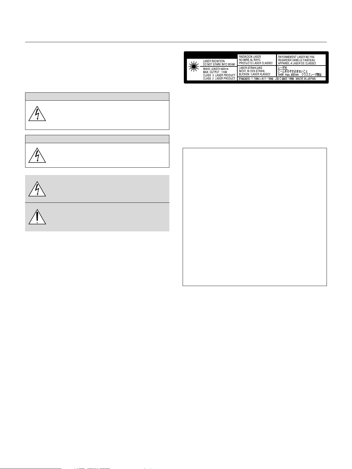
CAUTION
To turn off main power, be sure to remove the plug from
power outlet.
The power outlet socket should be installed as near to
the equipment as possible, and should be easily accessible.
CAUTION
TO PREVENT SHOCK, DO NOT OPEN THE CABINET.
NO USER-SERVICEABLE PARTS INSIDE.
REFER SERVICING TO QUALIFIED NEC SERVICE
PERSONNEL.
This symbol warns the user that uninsulated voltage
within the unit may be sufficient to cause electrical shock.
Therefore, it is dangerous to make any kind of contact
with any part inside of the unit.
This symbol alerts the user that important information
concerning the operation and maintenance of this unit
has been provided. The information should be read carefully to avoid problems.
WARNING
TO PREVENT FIRE OR SHOCK, DO NOT EXPOSE THIS UNIT TO
RAIN OR MOISTURE.
DO NOT USE THIS UNIT’S GROUNDED PLUG WITH AN EXTENSION CORD OR IN AN OUTLET UNLESS ALL THREE PRONGS CAN
BE FULLY INSERTED.
DO NOT OPEN THE CABINET. THERE ARE HIGH-VOLTAGE COMPONENTS INSIDE. ALL SERVICING MUST BE DONE BY QUALIFIED NEC SERVICE PERSONNEL.
DOC Compliance Notice
This Class B digital apparatus meets all requirements of the Canadian
Interference-Causing Equipment Regulations.
CAUTION
This label is on the side of the remote control.
RF Interference
WARNING
The Federal Communications Commission does not allow any
modifications or changes to the unit EXCEPT those specified by
NEC Technologies in this manual. Failure to comply with this government regulation could void your right to operate this equipment.
This equipment has been tested and found to comply with the
limits for a Class B digital device, pursuant to Part 15 of the FCC
Rules. These limits are designed to provide reasonable protection
against harmful interference in a residential installation. This equipment generates, uses, and can radiate radio frequency energy
and, if not installed and used in accordance with the instructions,
may cause harmful interference to radio communications. However, there is no guarantee that interference will not occur in a
particular installation. If this equipment does cause harmful interference to radio or television reception, which can be determined
by turning the equipment off and on, the user is encouraged to try
to correct the interference by one or more of the following measures:
• Reorient or relocate the receiving antenna.
• Increase the separation between the equipment and receiver.
• Connect the equipment into an outlet on a circuit different from that to
which the receiver is connected.
• Consult the dealer or an experienced radio / TV technician for help.
In UK, a BS approved power cable with moulded plug has a Black (five
Amps) fuse installed for use with this equipment. If a power cable is not
supplied with this equipment please contact your supplier.
3. GSGV Acoustic Noise Information Ordinance:
The sound pressure level is less than 70 dB (A) according to ISO 3744
or ISO 7779.
• IBM is a registered trademark of International Business Machines
Corporation.
•Macintosh and PowerBook are registered trademarks of Apple Computer, Inc.
• Other product and company names mentioned in this user's manual
may be the trademarks of their respective holders.
E – 2
Page 3
Important Safeguards
These safety instructions are to ensure the long life of your projector
and to prevent fire and shock. Please read them carefully and heed all
warnings.
Installation
1. For best results, use your projector in a darkened room.
2. Place the projector on a flat, level surface in a dry area away from
dust and moisture.
Ver tical angle of installation must be between -10° and +10° when
displaying an image.
Placing the projector outside of this range of angles may cause excess heat transfer to the lamp and shorten its life.
3. Do not place your projector in direct sunlight, near heaters or heat
radiating appliances.
4. Exposure to direct sunlight, smoke or steam can harm internal components.
5. Handle your projector carefully. Dropping or jarring can damage internal components.
6. Do not place heavy objects on top of the projector.
7. If you wish to have the projector installed on the ceiling:
a. Do not attempt to install the projector yourself.
b. The projector must be installed by qualified technicians in order to ensure
proper operation and reduce the risk of bodily injury.
c. In addition, the ceiling must be strong enough to support the projector
and the installation must be in accordance with any local building codes.
d. Please consult your dealer for more information.
To Dealer or Installer:
To prevent the projector from falling, install it in a place and fasten it in
a way with sufficient strength to support the combined weight of the
projector (7.2 kg/15.9 lbs) and a ceiling mount for an extended period
of time as well as to withstand earthquakes.
Power Supply
1. The projector is designed to operate on a power supply of 100-120
or 200-240 V 50/60 Hz AC. Ensure that your power supply fits this
requirement before attempting to use your projector.
2. Handle the power cable carefully and avoid excessive bending. A
damaged cord can cause electric shock or fire.
3. If the projector is not to be used for an extended period of time,
disconnect the plug from the power outlet.
Cleaning
1. Unplug the projector before cleaning.
2. Clean the cabinet periodically with a damp cloth. If heavily soiled,
use a mild detergent. Never use strong detergents or solvents such
as alcohol or thinner.
3. Use a blower or lens paper to clean the lens, and be careful not to
scratch or mar the lens.
CAUTION
Do not unplug the power cable from the wall outlet under any one
of the following circumstances. Doing so can cause damage to
the projector:
• While the Hour Glass icon appears.
• While the message "Please wait a moment." appears. This message
will be displayed after the projector is turned off.
• Immediately after the power cable is plugged into the wall outlet (the
POWER indicator has not changed to a steady orange glow).
• Immediately after the cooling fan stops working (The cooling fan con-
tinues to work for 2 minutes after the projector is turned off with the
POWER button).
• While the POWER and the STATUS indicators are alternately flashing.
CAUTION
To protect the Lens Shift mechanism, a hard polyurethane foam
pad is attached to the lens.
Before using the projector, remove the foam pad.
Reattach the foam pad before shipping this projector.
Lamp Replacement
•To replace the lamp, follow all instructions provided on page E-58.
• Be sure to replace the lamp when the message "The Lamp has
reached the end of its usable life. Please replace the lamp."
appears. If you continue to use the lamp after the lamp has reached
the end of its usable life, the lamp bulb may shatter, and pieces of
glass may be scattered in the lamp case. Do not touch them as the
pieces of glass may cause injury. If this happens, contact your NEC
dealer for lamp replacement.
• Allow a minimum of 2 minutes to elapse after turning off the projector. Then disconnect the power cable and allow 60 minutes to cool
the projector before replacing the lamp.
Fire and Shock Precautions
1. Ensure that there is sufficient ventilation and that vents are unobstructed to prevent the build-up of heat inside your projector. Allow
at least 3 inches (10 cm) of space between your projector and a
wall.
2. Prevent foreign objects such as paper clips and bits of paper from
falling into your projector. Do not attempt to retrieve any objects that
might fall into your projector. Do not insert any metal objects such as
a wire or screwdriver into your projector. If something should fall into
your projector, disconnect it immediately and have the object removed by a qualified NEC service personnel.
3. Do not place any liquids on top of your projector.
• Do not look into the lens while the projector is on. Serious damage
to your eyes could result.
•Keep any items such as magnifying glass out of the light path of the
projector. The light being projected from the lens is extensive, therefore any kind of abnormal objects that can redirect light coming out
of the lens, can cause unpredictable outcome such as fire or injury
to the eyes.
• Do not cover the lens with the supplied lens hood cap or equivalent
while the projector is on. Doing so can lead to melting of the cap and
possibly burning your hands due to the heat emitted from the light
output.
• Do not look into the laser pointer while it is on and do not point the
laser beam at another person. Serious injury could result.
CAUTION: Be careful when you take a PC card out of the PC card
slot because the PC card and the slot are hot during or immediately
after use.
CAUTION: Do not place hands near lens opening while shifting the
lens. Shifting the lens could pinch fingers or hands causing injury.
E – 3
Page 4

TABLE OF CONTENTS
1. INTRODUCTION
Introduction to the GT950 Projector ............................................. E-5
Getting Started ............................................................................. E-5
What's in the Box ......................................................................... E-6
Getting to Know Your GT950 Projector ........................................ E-7
Front / Side Features ............................................................. E-7
Rear / Side Features.............................................................. E-8
Attaching the lens hood cap ............................................ E-8
Carrying the Projector ..................................................... E-9
Setting the Projector for Vertical Placement ........................ E-10
Top Features ........................................................................ E-11
Te r minal Panel Features ...................................................... E-12
Remote Control Features .................................................... E-14
Remote Control Battery Installation .............................. E-16
Operating Range ........................................................... E-16
Remote Control Precautions ......................................... E-16
Switching operation mode between computer and projector ...
E-17
2. INSTALLATION
Setting Up Your Projector ........................................................... E-18
Selecting a Location ................................................................... E-18
Distance Chart ........................................................................... E-18
Ceiling Installation ............................................................... E-18
Screen and Projection Distance .......................................... E-19
Lens Shift Adjustable Range ...................................................... E-20
Wiring Diagram .......................................................................... E-21
Connecting Your PC or Macintosh Computer ...................... E-22
Connecting Your Computer to the Mouse Output Port ......... E-23
Connecting an External Monitor .......................................... E-24
Connecting a PC with DVI output ........................................ E-24
Connecting Your DVD Player ............................................... E-25
Connecting Your VCR or Laser Disc Player ......................... E-26
3. OPERATION
Connecting the Power Cable and Turning on the projector ........ E-27
About Startup Screen ................................................................ E-28
Set up the projector .................................................................... E-29
Other adjustments ...................................................................... E-30
Basic Operation ......................................................................... E-31
Adjust the Image Using Auto Adjust .................................... E-31
Volume Control .................................................................... E-32
Tu r ning off Picture and Sound ............................................. E-32
Getting Help about how to operate the projector ................. E-32
Using Pointer ....................................................................... E-32
Enlarging and Moving a Picture ........................................... E-32
Correcting Keystone Distortion ............................................ E-33
Freezing a Picture................................................................ E-33
Using the Menus ........................................................................ E-33
Customizing Basic/Custom Menu ........................................ E-33
Using a USB Mouse ................................................................... E-34
Menu Tree .................................................................................. E-35
Menu Elements .......................................................................... E-37
Menu Descriptions & Functions ................................................. E-38
Source Select ............................................................................. E-38
RGB, DVI (DIGITAL/ANALOG)/Video/S-Video/PC Card Viewer
Picture ........................................................................................ E-39
Brightness/Contrast/Color/Hue/Sharpness
Volume ....................................................................................... E-39
Image Options ............................................................................ E-39
Keystone .............................................................................. E-39
Lamp Mode .......................................................................... E-39
Aspect Ratio ........................................................................ E-40
Noise Reduction .................................................................. E-40
Position/Clock ...................................................................... E-40
Resolution ............................................................................ E-40
Video Filter .......................................................................... E-40
Overscan ............................................................................. E-40
Factory Default .................................................................... E-41
Color Management .................................................................... E-41
Color Temperature ............................................................... E-41
Gamma Correction .............................................................. E-41
Color Correction .................................................................. E-41
Color Matrix ......................................................................... E-41
White Balance ..................................................................... E-42
Projector Options ....................................................................... E-42
Sleep Timer ......................................................................... E-42
Menu .................................................................................... E-42
Menu Mode ................................................................... E-42
Advanced Menu, Basic/Custom Menu ...................... E-42
Language ...................................................................... E-42
Projector Pointer ............................................................ E-42
Menu Display Time ........................................................ E-43
Message (Source, No Input, Clean Filter) ..................... E-43
Direct Button (Volume Bar and Keystone Bar) .............. E-43
Setup ................................................................................... E-43
Orientation ..................................................................... E-43
Portrait ........................................................................... E-43
Background ................................................................... E-43
Mouse Settings ............................................................. E-43
Button/Sensitivity ....................................................... E-43
PC Card Viewer Options ............................................... E-44
Capture Options ............................................................ E-44
Signal Select ................................................................. E-44
Auto Adjust .................................................................... E-45
Auto Start ...................................................................... E-45
Power Management ...................................................... E-45
Power Off Confirmation ................................................. E-45
Keystone Save .............................................................. E-45
Continuous Operation ................................................... E-45
Built-in Speaker ............................................................. E-45
Clear Lamp Hour Meter ................................................. E-45
Clear Filter Usage ......................................................... E-45
Remote Sensor ............................................................. E-45
Control Panel Key Lock ................................................. E-45
S-Video Mode Select .................................................... E-45
Communication Speed .................................................. E-46
Default Source Select .................................................... E-46
LAN Mode ............................................................................ E-46
IP Address ..................................................................... E-46
Port, Gateway................................................................ E-46
Status ............................................................................ E-47
Lens ..................................................................................... E-47
Passcode ............................................................................. E-48
Tools ........................................................................................... E-48
Capture ................................................................................ E-48
PC Card Files ...................................................................... E-49
Changing Background Logo .......................................... E-49
Chalk Board ......................................................................... E-50
Help ............................................................................................ E-50
Contents .............................................................................. E-50
Information ........................................................................... E-50
Using the PC Card Viewer Function........................................... E-51
Features............................................................................... E-51
Inserting and Ejecting a PC Card ........................................ E-51
Installing the PC Card Viewer Software ............................... E-52
Starting Up the PC Card Viewer Software on your PC
(PC Card Viewer Utility 10) ........ E-52
Operating the PC Card Viewer Function from the Projector
(playback) .................................. E-53
Capturing Images Displayed on the Projector ..................... E-55
Viewing Digital Images ........................................................ E-55
Uninstalling the PC Card Viewer Software .......................... E-56
Te r minology ......................................................................... E-57
4. MAINTENANCE
Replacing the Lamp ................................................................... E-58
Cleaning or Replacing the Filters ............................................... E-59
5. TROUBLESHOOTING
Power / Status Light Messages .................................................. E-60
Common Problems & Solutions ................................................. E-60
6. SPECIFICATIONS
Optical/Electrical/Mechanical ..................................................... E-62
Cabinet Dimensions ................................................................... E-63
D-Sub Pin Assignments ............................................................. E-64
Compatible Input Signal List ...................................................... E-65
PC Control Codes ...................................................................... E-66
Cable Connection....................................................................... E-66
E – 4
Page 5

1. INTRODUCTION
Introduction to the GT950 Projector
This section introduces you to your new GT950 Projector and describes
the features and controls.
Congratulations on Your Purchase of The GT950
Projector
The GT950 is one of the very best projectors available today. The GT950
enables you to project precise images up to 300 inches across (measured diagonally) from your PC or Macintosh computer (desktop or
notebook), VCR, DVD player, document camera, a laser disc player or
PC Card Viewer.
You can use the projector on a tabletop or cart, you can use the projector to project images from behind the screen, and the projector can be
permanently mounted on a ceiling*1. The remote control can be used
wirelessly.
Features you’ll enjoy:
• Simple set up and operation.
• Placing the projector in a vertical position allows portrait display.
The supplied portrait software provides 90-degree clockwise image
rotation of the display to a portrait orientation (for PC only).
• The dedicated vertical stand will fix the projector in a vertical position.
• Hot air blown from the vents does not bother the audience during
your presentation since the vents are located at the front of the projector.
•A high-performance 200 watt NSH lamp.
• The supplied wireless remote control that operates the projector from
any angle.
• The image can be projected between 25 and 300 inches (measured
diagonally).
•Keystone correction allows you to correct trapezoidal distortion so
that the image is square.
•You can choose between video modes depending on your source:
"normal" for a typical picture, "natural" for true color reproduction.
• The built-in PC Card Viewer allows you to start your presentation
even when a PC is not available at the site.
• The "Capture" enables you to capture the current projected image.
• An image can be projected from in front or behind a screen, and the
projector can even be installed on the ceiling.
• NEC Technologies’ exclusive Advanced AccuBlend intelligent pixel
blending technology - an extremely accurate image compression
technology - offers a crisp image with UXGA (16001200) resolu-
2
tion*
.
• Supports most IBM VGA, SVGA, XGA, SXGA/UXGA(with Advanced
AccuBlend)*2, Macintosh, component signal (YCbCr / YPbPr) or any
other RGB signals within a horizontal frequency range of 15 to 100
kHz and a vertical frequency range of 48 to 120 Hz. This includes
NTSC, PAL, PAL-M, PAL-N, PAL60, SECAM and NTSC4.43 standard video signals.
NOTE: Composite video standards are as follows:
NTSC: U.S. TV standard for video in U.S. and Canada.
PAL: TV standard used in Western Europe.
PAL-M: TV standard used in Brazil.
PAL-N: TV standard used in Argentina, Paraguay and Uruguay.
PAL60: TV standard used for NTSC playback on PAL TVs.
SECAM: TV standard used in France and Eastern Europe.
NTSC4.43: TV standard used in Middle East countries.
*1Do not attempt to mount the projector on a ceiling yourself. The pro-
jector must be installed by qualified technicians in order to ensure
proper operation and reduce the risk of bodily injury. In addition, the
ceiling must be strong enough to support the projector and the installation must be in accordance with any local building codes. Please
consult your dealer for more information.
*2A UXGA (16001200) and SXGA image (12801024) are displayed
with NEC technology’s Advanced AccuBlend.
*3The PC Control Utility 1.0 is required. This program is included on
the supplied CD-ROM.
*4The USB terminal meets the USB1.1 specification and accepts a
USB mouse only.
Getting Started
The fastest way to get started is to take your time and do everything
right the first time. Take a few minutes now to review the user’s manual.
This may save you time later on. At the beginning of each section of
the manual you’ll find an overview. If the section doesn’t apply, you can
skip it.
• The supplied remote control can be used without a cable, and you
can even use the remote control and mouse adapter to operate your
PC or Macintosh mouse wirelessly from across the room with the
built-in remote mouse receiver.
•You can control the projector with a PC using the PC Control port*3.
• USB terminal allows USB mouse operation *4.
• The contemporary cabinet design is light, compact, easy to carry,
and complements any office, boardroom or auditorium.
• Eight pointers are available for your presentation.
E – 5
Page 6
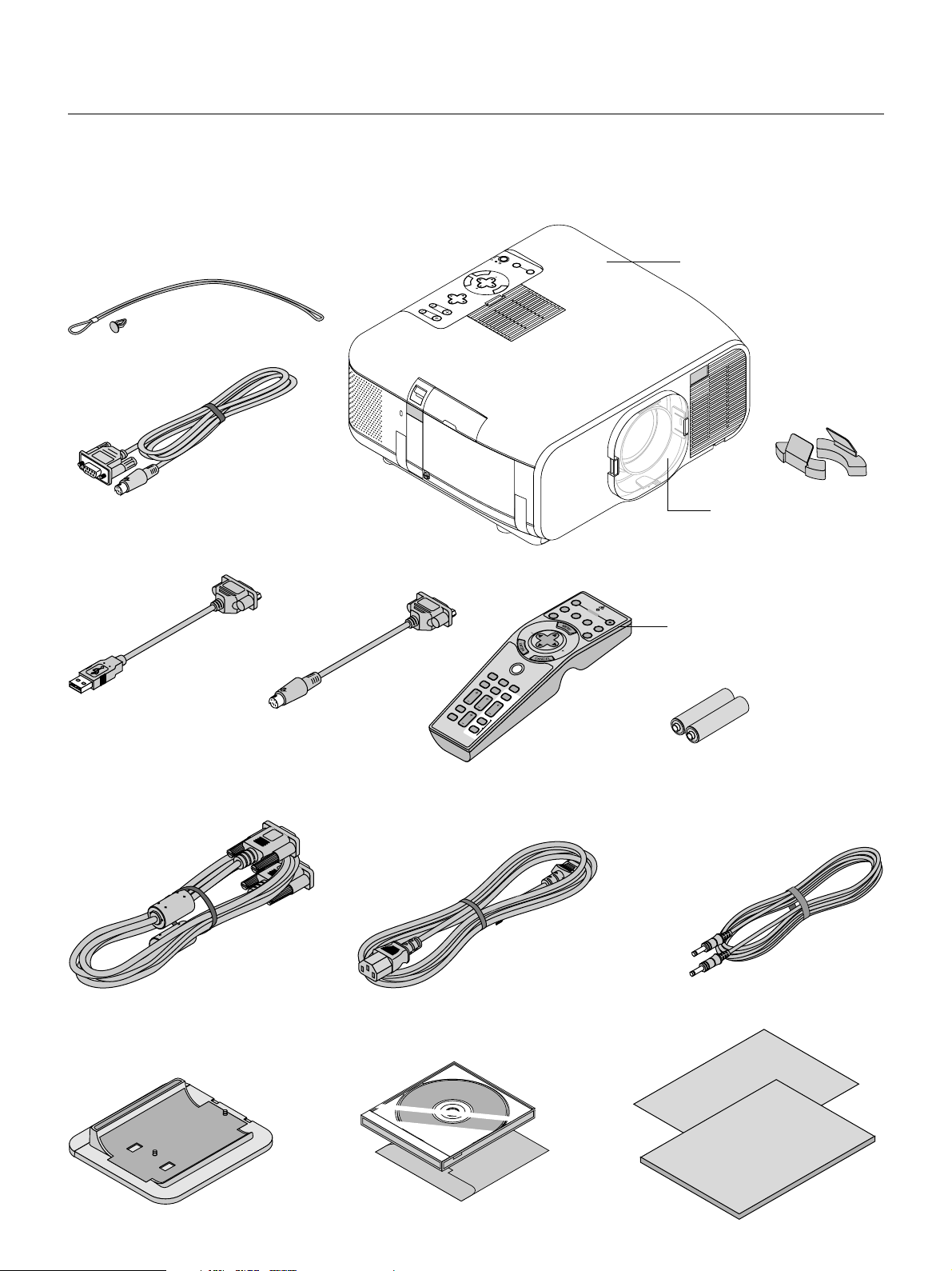
What's in the Box?
Make sure your box contains everything listed. If any pieces are missing, contact your dealer.
Please save the original box and packing materials if you ever need to ship your GT950 Projector.
ON/STAND BY
POWER
STATUS
ADJUST
AUTO
N
E
T
E
R
String and rivet
Serial cable
Mouse adapter
(USB)
Mouse adapter
(For IBM PS/2)
C
A
N
C
E
L
LENS SHIFT
FOCUS
ZOOM
KEYSTONE
F
R
E
E
ZE
VOL.
P
IC
-M
U
T
E
S
LID
LIST
SOURCE
SELECT
M
E
N
U
O
FF
VID
E
O
S
A
P
U
-VID
O
T
W
O
A
E
E
D
R
O
J
.
R
G
B1
R
G
B
2
LA
S
E
SELECT
P
J
FOCUS ZOOM
HELP
SHIFT
P
O
IN
T
E
R
P
C
C
M
A
A
R
G
D
N
IFY
SLIDE
F
O
LD
E
R
E
R
NEC GT950 projector
Lens protection
spacer
Lens hood cap
O
N
Remote control
Batteries (AA2)
RGB signal cable
(15-Pin Mini D-Sub To 15-Pin Mini D-Sub connector)
Vertical Stand
Power cable
CD-ROM1
(NEC projector user
supportware)
Remote cable
Quick Connect Guide
User's Manual
CD-ROM2
(NEC projector user
supportware 2)
E – 6
Page 7
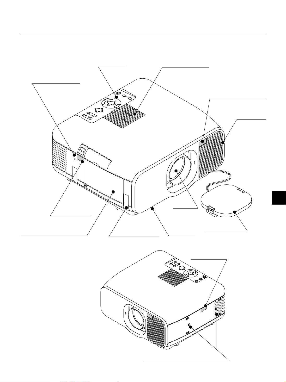
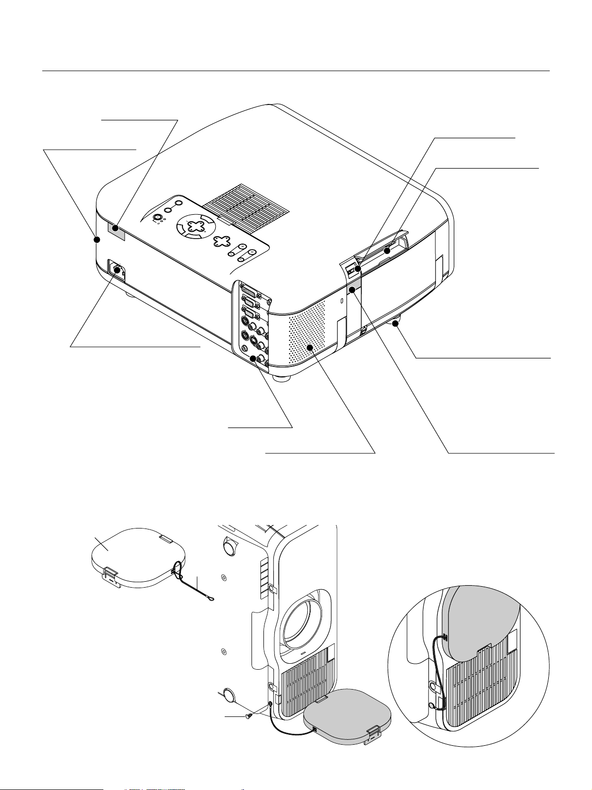
Getting to Know Your GT950 Projector
Front/Side Features
Controls
Slot for Kensington Micro
saver Security System
O
N
/S
P
O
T
S
W
A
T
N
E
A
D
R
T
B
A
U
D
Y
S
A
J
U
U
T
S
O
T
N
E
T
E
R
C
A
N
S
E
C
L
E
E
C
L
T
L
E
N
S
S
H
IF
F
T
O
C
U
S
Z
O
O
M
S
O
U
R
C
E
M
E
N
U
Air-Filter
Remote Sensor
Air-Filter
Lamp Cover
Remote Sensor
Carrying Handle
Lens
Ventilation
(outlet)
M
O
O
Z
S
U
C
O
F
T
IF
H
S
S
N
LE
Lens hood cap
Remote Sensor
L
E
C
N
A
C
Y
R
B
T
E
D
C
N
T
E
A
L
N
T
E
E
R
/S
S
E
N
S
O
W
U
U
N
E
M
O
T
P
A
T
S
T
S
U
J
O
D
T
A
U
A
E
C
R
U
O
S
Stand attachment portion
E – 7
Page 8
A
U
D
IO
IN
A
U
D
IO
IN
A
U
D
IO
O
U
A
U
D
IO
O
U
T
DVI-I IN
RGB IN
RGB OUT
PC CONTROL
MOUSE
OUTPUT
REMOTE
CONTROL
INPUT
AUDIO IN
AUDIO IN
R
L/
MONO
VIDEO
S-VIDEO
Rear/Side Features
Remote Sensor
Built-In Stereo Speaker (2W)
A
C
IN
AC Input
Connect the supplied power cable’s threepin plug here.
USB (Mouse) Terminal
PC Card Slot
SOURCE
AU
ADJUST
TO
M
E
STATU
PO
W
S
O
ER
N/STAN
D BY
N
U
SELECT
E
N
T
E
R
C
A
N
C
L
E
LENS SHIFT
FO
CUS
ZO
OM
Foot
Terminal Panel
Built-In Stereo Speaker (2W) Remote Sensor
Attaching the lens hood cap to the bottom with the supplied string and rivet.
1. Thread the string through the hole on the
lens hood cap.
Lens hood cap
String
2. Use the rivet to attach the string to the bottom of the projector.
Rivet
E – 8
Page 9
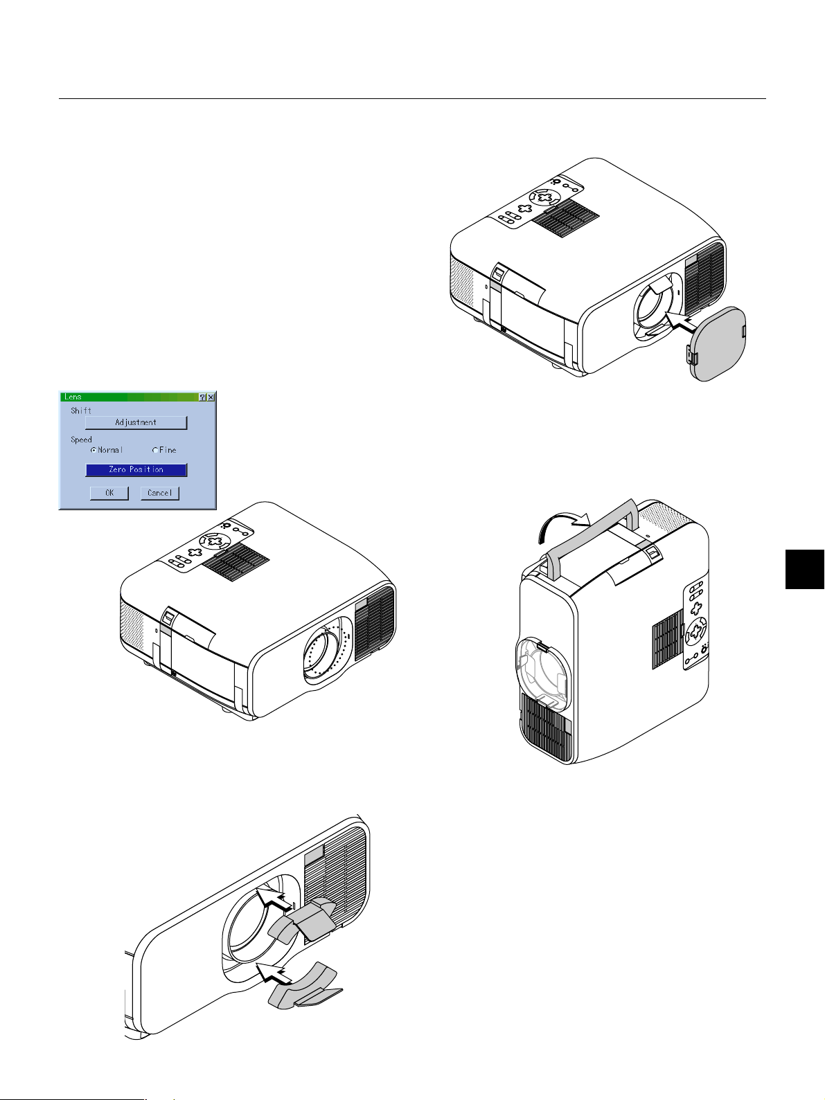
Carrying the Projector
Always carry your projector by the handle. Ensure that the power cable
and any other cables connecting to video sources are disconnected
before moving the projector.
When moving the projector or when it is not in use, cover the lens with
the lens hood cap.
The lens mechanism consists of precision parts. Be sure to mount the
included lens protection spacers to the lens unit when shipping or
moving the GT950.
1. Returning the Lens Shift to Center
If the lens position is not centered, it should be moved.
Move the lens to the center by going to “Projector Options” → “Lens”,
then “Zero Position” of the menu. (See Page E-47.)
*To use the remote control for this, press the SHIFT button to bring
up the Lens Shift display, then move the lens to center with the SELECT ▲▼
play. (See Page E-29.)
buttons. Press the CANCEL button to close the dis-
3. Attach the Supplied Lens Hood Cap
Lens hood cap
4. Extend the Carrying Handle
Grasp the carrying handle to move the projector.
Carrying handle
2. Insert the Supplied Lens Protection Spacer Above and Below
the Lens
If the lens is not in the center position, the lens protection spacer
might not enter or excessive force could be applied to the lens mechanism.
Be certain to insert the upper and lower portions all the way to the
back.
Lens protection spacer
E – 9
Page 10
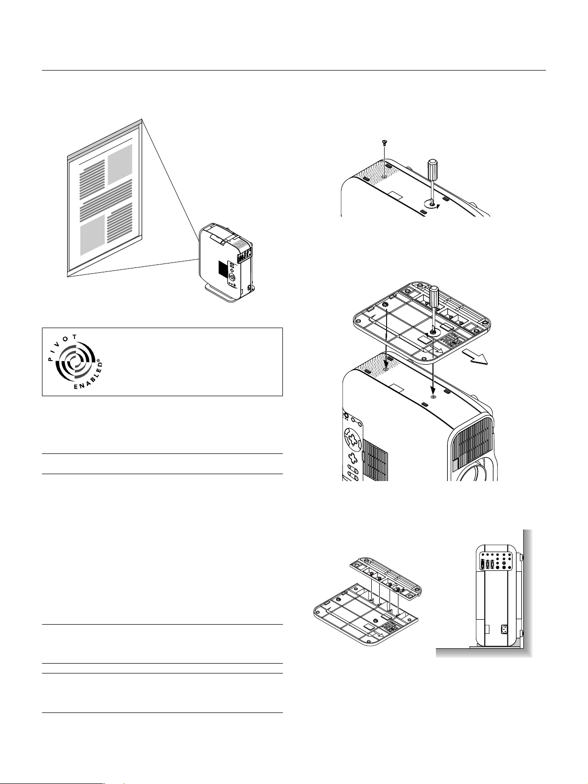
Setting the Projector for Vertical Placement
This projector has a portrait function that supports the portrait display
setting of a personal computer.
A
B
D
Pivot® software included in the supplied CD-ROM2
If the personal computer does not have a driver
for portrait display, install the dedicated driver
from the supplied CD-ROM2. See the manual
supplied with the CD-ROM2 for details.
To use this function, attach the supplied stand to the projector and
place the projector to stand vertically.
1. Remove the 2 Screws of the Main Unit
Keep these screws in a safe place.
2. Attach the Supplied Vertical Stand to the Screw Holes of the
Main Unit
Place the Projector Upright and Use Check that the portrait setting
is to “Auto” or “On” under “Projector Options” → “Setup” → “Page 1”
of the menu. (See Page E-43)
Pivot® and the Pivot Enabled® logo are registered trademarks of Portrait Displays, Inc. Copyright 1993-2000 Portrait Displays, Inc. All Rights
Reserved.
U.S. PAT. #5,973,664
NOTE: We do not support the Pivot® software because of a sample. This sample
software is not covered under the warranty.
1 Installation
For installation, see the instructions in the WINPORTRAITR® INSTRUCTIONS included with the supplied CD-ROM2.
2. To rotate the display on a PC, use any of the three following methods:
* Right-click anywhere on the desktop, and then select “Rotate” from
the shortcut menu.
* Left-click the Pivot® icon on the taskbar, and then select “Rotate”
from the shortcut menu.
* Press the Ctrl, Shift, and R keys at the same time.
3. To return the display to the landscape orientation
Repeat any one of the three methods above.
NOTE:
* This driver is for exclusive use with Windows 95/98/Me/NT 4.0/2000 and
angle of 270 degrees counterclockwise rotation only.
* Left-click the Pivot icon on the taskbar and then select “Help” to get help.
NOTE: See the installation method described in the supplied CD-ROM2 for installation details.
See Page E-43 for information about making the on-screen display support the
portrait display mode.
O
N
P
/S
O
S
W
T
T
A
A
A
E
A
D
N
T
R
U
J
U
D
U
T
S
B
S
O
T
Y
S
O
E
U
N
T
R
E
R
C
E
C
S
A
E
L
N
E
C
C
T
M
E
L
E
N
U
LE
FT
D
O
W
LEN
N
S SH
IFT
U
P
F
O
R
C
IG
U
H
T
S
Z
O
O
M
Corner Placement of the Projector
Tu rn the 4 screws of the vertical stand’s auxiliary stand counterclockwise until they turn freely; they will not come out. Then, remove the
auxiliary stand.
Attach the stand to the main unit after this.
· Do not use the projector with the top surface against a wall.
Doing so will block the ventilation openings and the internal
temperature will rise.
· Do not place the projector with the lamp side (i.e., the side on
which the handle is located) facing downward. This could lead
to the projector breaking down.
E – 10
Page 11
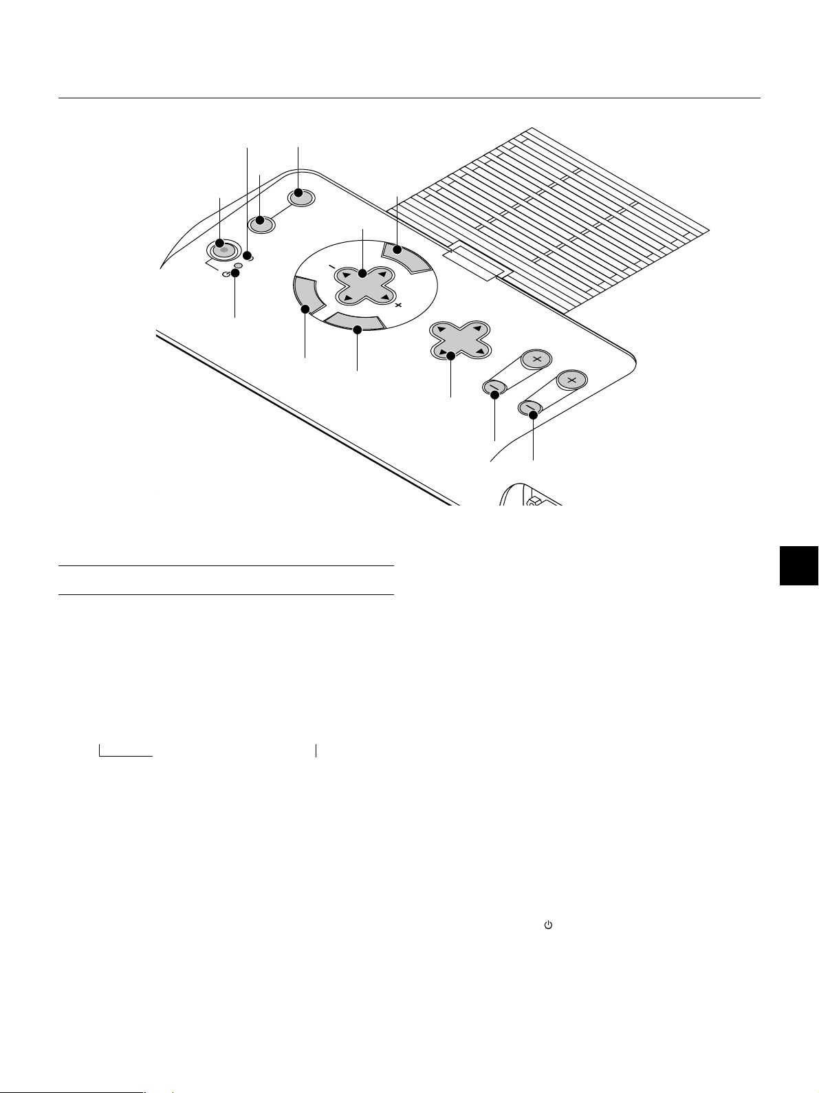
Top Features
11 3
1
STATUS
POWER
ON/STAND BY
12
2
AUTO
ADJUST
E
N
T
E
R
SOURCE
C
A
5
SELECT
N
C
E
4
M
E
N
U
L
LENS SHIFT
6
7
1. Power Button (ON / STAND BY)
Use this button to turn the power on and off when the power is supplied and the projector is in standby mode.
NOTE: To turn off the projector, press and hold this button for a minimum of
two seconds.
2. Auto Adjust Button
Use this button to adjust an RGB or DVI (digital/analog) source for an
optimal picture. Some signals may not be displayed correctly or take
time to switch between sources.
3. Source Button
Use this button to select a video source such as a PC, VCR, DVD
player or PC Card Viewer (PC card).
Each time this button is pressed, the input source will change as follows:
→ RGB → Video → S-Video → DVI (DIGITAL)
PC Card Viewer ← DVI (ANALOG) ←
If no input signal is present, the input will be skipped.
4. Menu Button
Displays the menu.
5. Select ▲▼ / Volume (+) (-) Buttons
▲▼: Use these buttons to select the menu of the item you wish to
adjust.
When no menus appear, these buttons work as a volume control.
: Use these buttons to change the level of a selected menu item.
A press of the button executes the selection.
When the menus or the Viewer tool bar is not displayed, these
buttons can be used to select a slide, or to move the cursor in
Folder List or Slide List.
When the pointer is displayed, these ▲▼ buttons move
the pointer.
FOCUS
8
ZOOM
10
9
6. Enter Button
Executes your menu selection and activates items selected from the
menu.
7. Cancel Button
Press this button to exit "Menus". Press this button to return the adjustments to the last condition while you are in the adjustment or setting
menu.
8. Lens Shift Button
Adjust the lens offset by shifting the projected image position horizontally, vertically or diagonally.
9. Zoom Button
Zoom the lens in and out.
10. Focus Button
Adjust the lens focus.
11. Status Indicator
When this is lit red (orange in Eco mode) continually, it's warning you
that the projection lamp has exceeded 1500 hours (2000 hours in Eco
mode) of service. After this light appears, it is advisable to replace the
projection lamp as soon as possible. (See page E-58). In addition the
message "The lamp has reached the end of its usable life. Please replace the lamp." appears continually until the lamp is replaced.
If this light blinks red rapidly, it indicates that the lamp cover is not
attached properly or the projector is overheated.
See the Power / Status Light Messages on page E-60 for more details.
12. Power Indicator ( )
When this indicator is green, the projector is on; when the indicator is
orange, it is in standby mode.
E – 11
Page 12
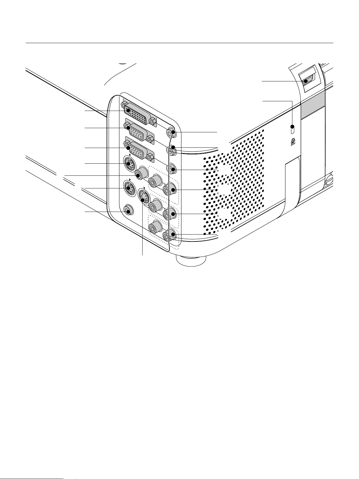
Terminal Panel Features
ZO
1
OM
15
USB
16
DVI-I IN
2
RGB IN
AUDIO IN
3
L/
MONO
AUDIO IN
AUDIO IN
AUDIO OUT
AUDIO IN
AUDIO OUT
RGB OUT
4
5
PC CONTROL
VIDEO
6
MOUSE
OUTPUT
S-VIDEO
REMOTE
8
CONTROL
INPUT
7
1. DVI-I Input Connector (DVI 29 pin)
This connector can be used to accept digital or analog signal output
from a computer with a DVI connector.
2. RGB Input Connector (Mini D-Sub 15 pin)
Connect your PC or other RGB equipment. Use the signal cable that's
supplied to connect to a PC.
3. RGB Output Connector (Mini D-Sub 15 pin)
You can use this connector to loop your computer image to an external
monitor from the RGB input source.
DVI digital signal will not be output. The last selected RGB analog
signal will be output while a Video or S-Video signal is viewed.
4. PC Control Port (Mini DIN 8 Pin)
Use this port to connect your PC to control your projector via a serial
cable. This enables you to use your PC and serial communication protocol to control the projector. The NEC optional serial cable is required
to use this port. Also PC Control Utility 1.0 included in the supplied CDROM1 must be installed on your PC.
If you are writing your own program, typical PC control codes are on
page E-66.
A cap is put on the port at the factory. Remove the cap when using the
port.
5. Video Input Connector (RCA)
Connect a VCR, DVD player, laser disc player, or document camera
here to project video.
9
10
11
R
12
13
14
7. S-Video Input Connector (DIN 4 pin)
Here is where you connect the S-Video input from an external source
like a VCR.
8. Remote Control Input Jack
Connect your remote control cable here for wired operation.
9. DVI Audio Input Mini Jack
This is where you connect audio output from your equipment connected
to DVI-I INPUT connector.
10. RGB Audio Input Mini Jack
This is where you connect RGB audio output from a computer or another RGB source.
11. Audio Output Mini Jack
Connect additional external speakers here to listen to audio coming
from your computer, Video or S- Video input.
12. VIDEO Audio Input Jacks (RCA)
L/MONO
This is your left channel audio input for stereo sound coming from the
VIDEO source.
This also serves as your monaural audio input.
R
This is your right channel audio input for stereo sound from the VIDEO
source.
6. Mouse Output Port (Mini DIN 8 Pin)
Use this port to operate your computer's mouse functions from the
remote control.
E – 12
Page 13
DVI IN
R
19
18
USB
17
L/
MONO
AUDIO IN
AUDIO IN
AUDIO OUT
RGB IN
RGB OUT
C CONTROL
13. S-VIDEO Audio Input Jacks (RCA)
L/MONO
This is your left channel audio input for stereo sound coming from the
S-VIDEO source.
This also serves as your monaural audio input.
R
This is your right channel audio input for stereo sound from the SVIDEO source.
14. Audio Output Jacks (RCA)
You can use this connector to output sound from the currently selected
input source (RGB, VIDEO, S-VIDEO or DVI[digital/analog] ). Output
sound level can be adjusted in accordance
with the sound level of the internal speaker.
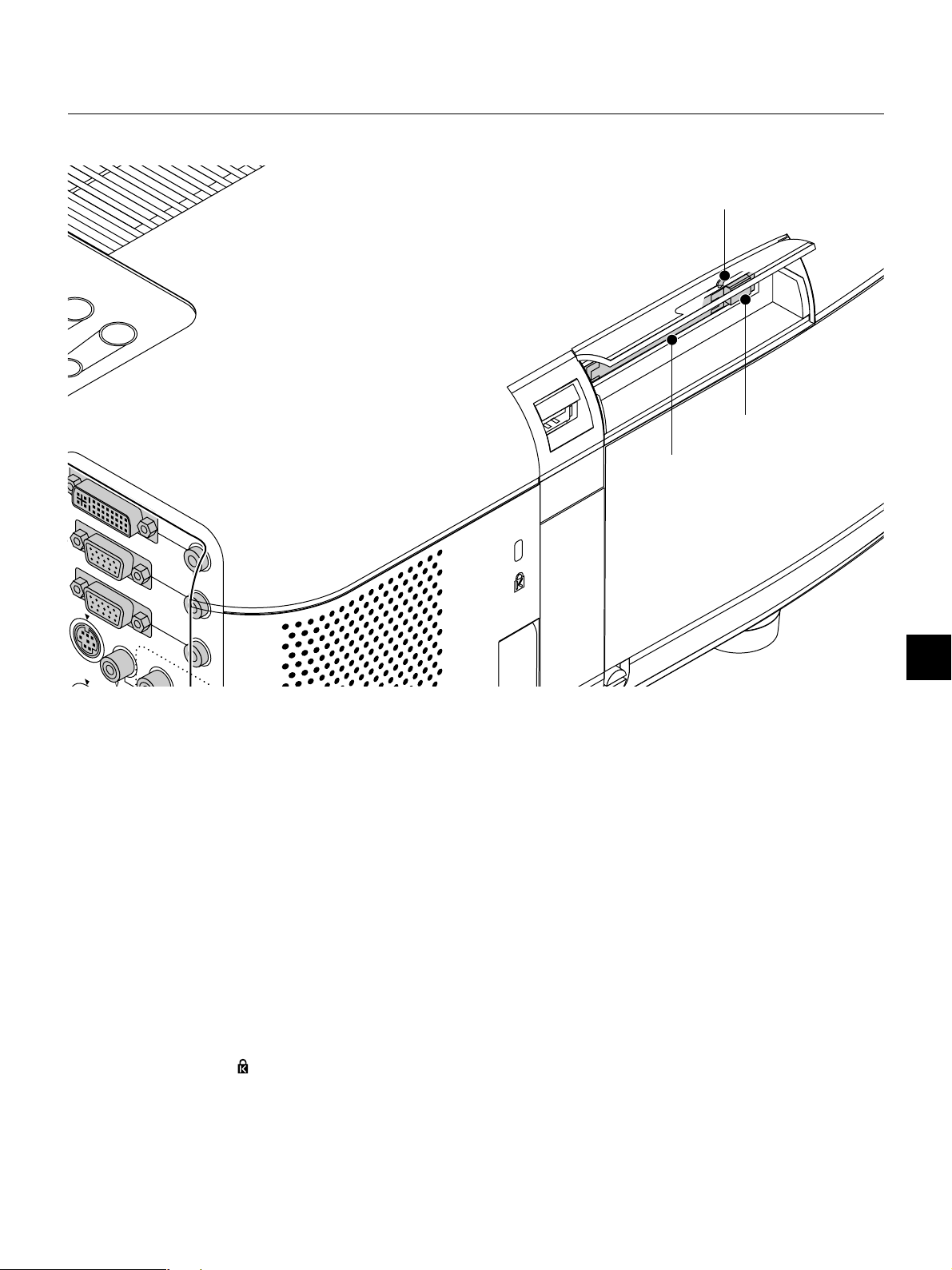
15. USB Terminal
Connect a commercially available mouse that supports USB. You can
operate the menu or PC Card Viewer with the USB mouse via this
terminal.
Note that this terminal is not used with a computer and that there may
be some brands of USB mouse that the projector does not support.
17. PC Card Slot
Insert a PC card here.
18. PC Card Eject Button
Press to eject a PC card.
19. PC Card Access Indicator
Lights while accessing a PC card.
16. Built-in Security Slot ( )
This security slot supports the MicroSaver® Security System.
MicroSaver® is a registered trademark of Kensington Microware
Inc. The logo is trademarked and owned by Kensington Microware Inc.
E – 13
Page 14
Remote Control Features
0
2
4
6
NOTE: If you are using a Macintosh computer, you can click either the rightclick or left-click button to activate the mouse.
NOTE: If any one of the buttons is pressed and held for 60 seconds or more,
the button operations will cease to operate. This is not a malfunction, rather it
is a feature used to prolong battery power. To cancel this feature, press any one
of the buttons other than the SELECT button.
T
IS
L
SLIDE
FOLDER
.
L
E
ID
L
PC CARD
T
IF
H
S
M
O
O
Z
J
P
SELECT
LASER
RGB2
ON
POWER
AUTO ADJ.
S-VIDEO RGB1
VIDEO
OFF
O
U
C
POINTER
P
O
F
MAGNIFY
L
E
H
V
KEYSTONE
FREEZE
PIC-MUTE
S
S
3
1
2
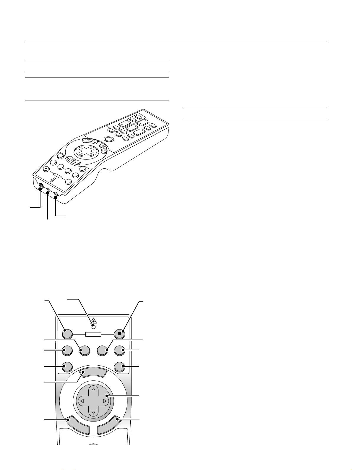
1. Infrared Transmitter
Direct the remote control toward the remote sensor on the projector
cabinet.
2. Laser Pointer
Beams a laser light when "Laser" button is pressed.
3. Remote Jack
Connect your remote control cable here for wired operation.
4. LED
Flashes when any button is pressed.
5. Power ON Button
If the main power is applied, you can use this button to turn your projector on.
6. Power OFF Button
If the main power is applied, you can use this button to turn your projector off.
NOTE: To turn off the projector, press and hold the POWER OFF button for a
minimum of two seconds.
7. VIDEO Button
Press this button to select an NTSC, PAL, SECAM or NTSC4.43 compatible video source from a VCR, DVD player, laser disc player or document camera.
8. S-VIDEO Button
Press this button to select an S-Video source from a VCR.
9. RGB 1 Button
Press this button to select a video source from computer or component equipment connected to your RGB port.
10. RGB 2 Button
Press this button to select DVI analog or DVI digital signal from a PC
with DVI output to the DVI-I INPUT connector.
The RGB 2 button toggles between DVI analog and DVI digital.
11. AUTO ADJ Button
Use this button to adjust an RGB or DVI (digital/analog) source for an
optimal picture. Some signals may not be displayed correctly or take
time to switch between sources.
12. LASER Button
Press and hold this button to activate the laser pointer. When lit, you
can use the laser to draw your audience's attention to a red dot that
you can place on any object.
13. MENU Button
Displays the menu for various settings and adjustments.
6
8
7
11
13
15
4
OFF
VIDEO
AUTO ADJ.
E
N
POWER
S-VIDEO RGB1 RGB2
LASER
N
E
U
M
SELECT
T
E
R
PJ
E
C
N
A
C
L
ON
14. SELECT (▲▼
5
When you are in the Computer mode, these buttons work as a computer mouse.
) (Mouse) Button
When you are in the Projector mode, which is indicated by lighting the
PJ button:
▲▼: Use these buttons to select the menu of the item you wish to adjust.
:Use these buttons to change the level of a selected menu item.
A press of the button executes the selection.
9
1
When the pointer is displayed, these ▲▼
15. ENTER (Left Click) Button
buttons move the pointer.
When you are in the Computer mode, this button works as the mouse
left button.
1
When this button is pressed and held for a minimum of 1.5 seconds,
the drag mode is set.
When you are in the Projector mode, which is indicated by lighting the
PJ button:
Use this button to enter your menu selection. It works the same way as
1
the "Enter" button on the cabinet.
16. CANCEL (Right Click) Button
When you are in the Computer mode, this button works as the mouse
1
right button.
When you are in the Projector mode, which is indicated by lighting the
PJ button:
Press this button to exit "Menus". It works the same way as the “Cancel” button on the cabinet.
E – 14
Page 15

7
9
0
8
9
0
22
ON
OFF
18
21
23
24
25
26
27
PJ
FOCUS ZOOM
HELP
POINTER
KEYSTONE
MAGNIFY
FREEZE
VOLUME
PIC-MUTE
SHIFT
PC CARD
SLIDE
FOLDER
SLIDE
LIST
1
1
2
2
2
3
31
26. PICTURE MUTE Button
This button turns off the image and sound for a short period of time.
Press again to restore the image and sound.
NOTE: When the menu is displayed, a press of this button mutes an
image and sound without turning off the menu.
27. VOLUME (+) (–) Button
Press (+) to increase the volume and (–) to decrease it.
28. PC CARD Button
Press this button to select the PC Card Viewer source.
29. SLIDE (+) (–) Button
Press (+) to select the next folder or slide and (–) to select the previous
folder or slide.
30. FOLDER LIST Button
Press this button to select PC Card Viewer source to display a list of
folders included in a PC card.
31. SLIDE LIST Button
Press this button to select PC Card Viewer source to display a list of
slides included in a PC card.
17. PJ Button
Press this button to switch the Select, Cancel, and Enter buttons between the Projector mode (lit red) and the Computer mode. Press this
button or any one of the Power ON/OFF, Menu, Focus, Zoom, Shift,
Help, Pointer, Magnify, PC Card, Folder List or Slide List buttons to
switch to the Projector mode and the PJ button lights red. To switch
back to the Computer mode, press the PJ button again.
18. FOCUS Button
Press this button to display the Focus adjustment window. Use the
Select + or - button to obtain the best focus.
19. ZOOM Button
Press this button to display the Zoom adjustment window. Use the Select
+ or - button to zoom in or out.
20. SHIFT Button
Press this button to display the Shift adjustment window. Use the Select , , ▲, or ▼ button to shift the lens horizontally, vertically or
diagonally.
21. HELP Button
Provides information about operation and adjustment procedures or
the set information for the current menu or adjustment during menu
operation.
22. POINTER Button
Press this button to display one of the eight pointers; press again to
hide the pointer. You can move your pointer icon to the area you want
on the screen using the Select button.
23. KEYSTONE (+) (–) Button
Press the (+) or (–) button to correct the keystone (trapezoidal) distortion, and make the image square.
24. MAGNIFY (+) (–) Button
Use this button to adjust the image size up to 400%.
When the pointer is displayed, the image is magnified about the center
of the pointer. When the pointer is not displayed, the image is magnified about the center of the screen.
When the image is magnified, the pointer is changed to the magnifying
icon.
25. FREEZE Button
This button will freeze a picture. Press again to resume motion.
*NOTE: The default is the Computer mode, which allows you to use the Select,
Cancel, and Enter buttons as your computer mouse. When the POWER ON/
OFF, MENU, FOCUS, ZOOM, SHIFT, HELP, POINTER, MAGNIFY, PC CARD,
FOLDER LIST, or SLIDE LIST button is pressed, the PJ button lights red to
indicate that you are in the Projector mode. If no buttons are pressed within 10
seconds, the light goes out and the Projector mode is canceled.
Setting the function switch
There are two switches on the bottom of the battery case: an applicable projector selector switch (1) and laser enable/disable switch (2).
Check the projector being used and decide whether to enable or disable laser, then set these switches as necessary using the tip of a thin
ball-point pen.
On this model, an applicable projector selector switch (1) is not used.
Switch (2)
On: Enabled (the laser lights when the LASER button is pressed) [Factory default]
Off: Disabled (the laser does not light even when the LASER button is
pressed)
Disable the laser when using in an environment in which the unit is
accessible to children.
E – 15
Page 16
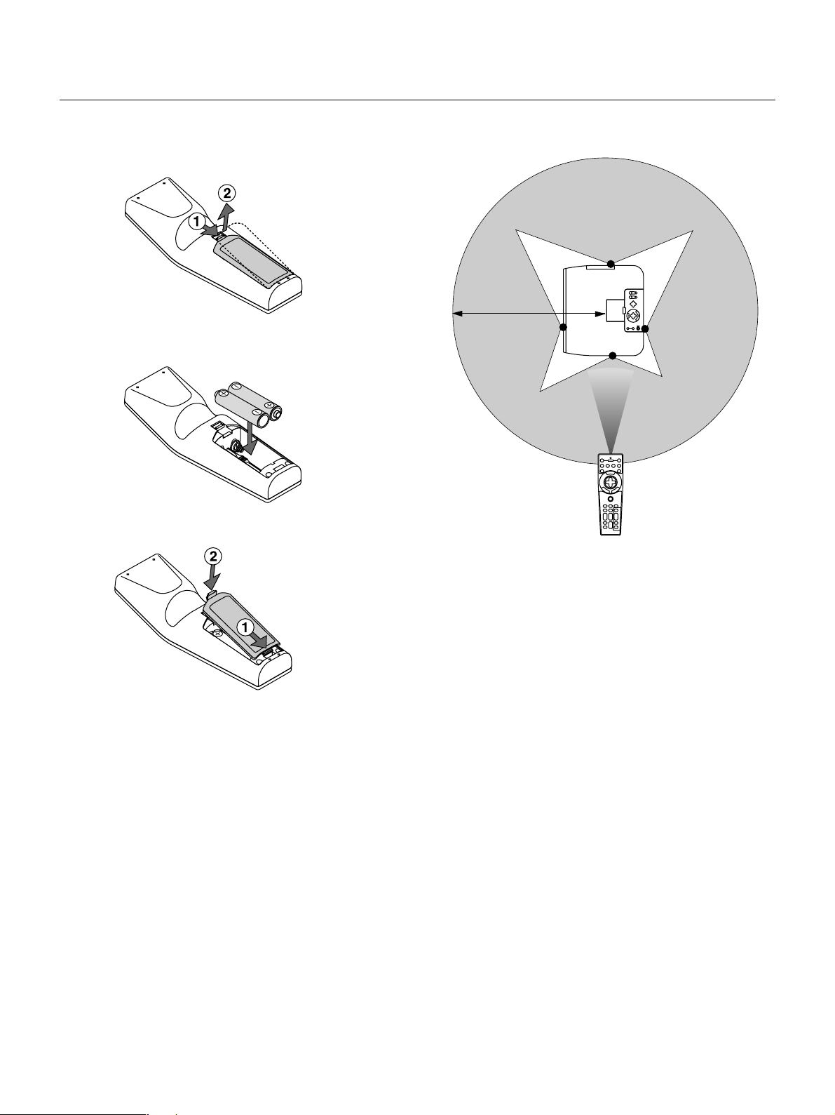
1. Press firmly and slide the battery cover off.
2. Remove both old batteries and install new ones (AA). Ensure that
you have the batteries' polarity (+/–) aligned correctly.
3. Slip the cover back over the batteries until it snaps into place.
Operating RangeRemote Control Battery Installation
7m
Do not mix different types of batteries or new and old batteries.
Remote Control Precautions
• Handle the remote control carefully.
• If the remote control gets wet, wipe it dry immediately.
•Avoid excessive heat and humidity.
• If you will not be using the remote control for a long time, remove the
batteries.
• Do not place the batteries upside down.
• Do not look into the laser pointer while it is on.
• Do not point the laser beam at a person.
E – 16
Page 17
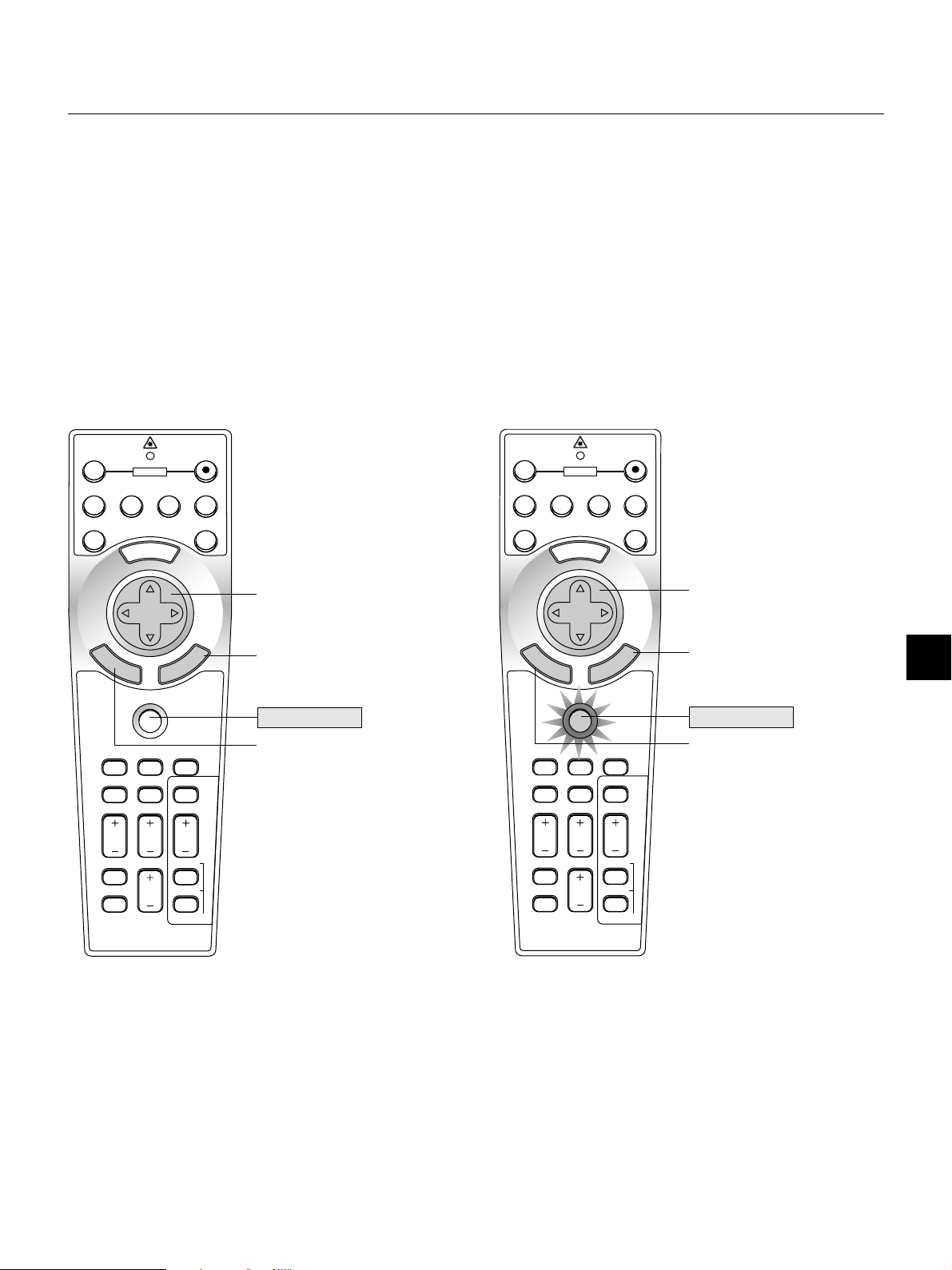
Switching operation mode between computer and projector
The three shaded buttons shown on the drawing work as a computer mouse in the Computer mode.
In the Computer mode the PJ button is not lit.
• When the MENU button is pressed, the PJ button lights red to indicate that you are in the Projector mode, which allows the projector menu
operation using the three buttons.
• When the POINTER button is pressed, the PJ button lights red to indicate that you are in the Projector mode and that the SELECT ▲▼
button
works as a moving button for the POINTER or magnified image.
• If no buttons are pressed within 10 seconds, the PJ button's light goes out to indicate that you are in the Computer mode. To enable the projector
menu operation again, press the PJ button to light red. To move the pointer or a magnified image again, turn off the pointer and then turn on the
pointer (press the POINTER button two times).
• When the PJ button is lit, if you want to use the mouse function immediately, press the PJ button to return to the Computer mode (not lit).
OFF
VIDEO
S-VIDEO RGB1 RGB2
AUTO ADJ.
E
N
T
E
R
FOCUS ZOOM
HELP
KEYSTONE
POWER
N
E
M
SELECT
PJ
POINTER
MAGNIFY
U
C
N
A
C
SHIFT
PC CARD
SLIDE
ON
LASER
L
E
Works as a mouse for your
computer.
Works as a right-click button for
your computer.
Not lit
Works as a left-click button for
your computer.
OFF
VIDEO
S-VIDEO RGB1 RGB2
AUTO ADJ.
E
N
T
E
R
FOCUS ZOOM
HELP
KEYSTONE
POWER
N
E
M
SELECT
PJ
POINTER
MAGNIFY
U
C
N
A
C
SHIFT
PC CARD
SLIDE
ON
LASER
L
E
Works as the Select button on
the projector.
Works as the Cancel button on
the projector.
Lit red
Works as the Enter button on
the projector.
FREEZE
VOLUME
FOLDER
PIC-MUTE
SLIDE
LIST
During Computer mode:
During Computer mode by pressing the ENTER button for 1.5 seconds or more then releasing, the drag mode is set and the drag operation can be performed simply by pressing the SELECT (▲, ▼, , )
(mouse) button. To cancel the drag mode, press the ENTER (left click)
button again or press the CANCEL (right click) button.
E – 17
FREEZE
PIC-MUTE
VOLUME
FOLDER
SLIDE
LIST
Page 18
2. INSTALLATION
This section describes how to set up your GT950 projector and how to
connect video and audio sources.
Setting up Your Projector
Your GT950 Projector is simple to set up and use. But before you get
started, you must first:
1. Determine the image size.
2. Set up a screen or select a non-glossy white wall onto which you
can project your image.
3. Connect the supplied power cable.
4. Set up the projector.
5. Connect a PC, VCR, DVD player, or other equipment.
6. Make setting or adjustments on the projector.
Distance Chart
Standard Lens (H2.0) – (H2.4)
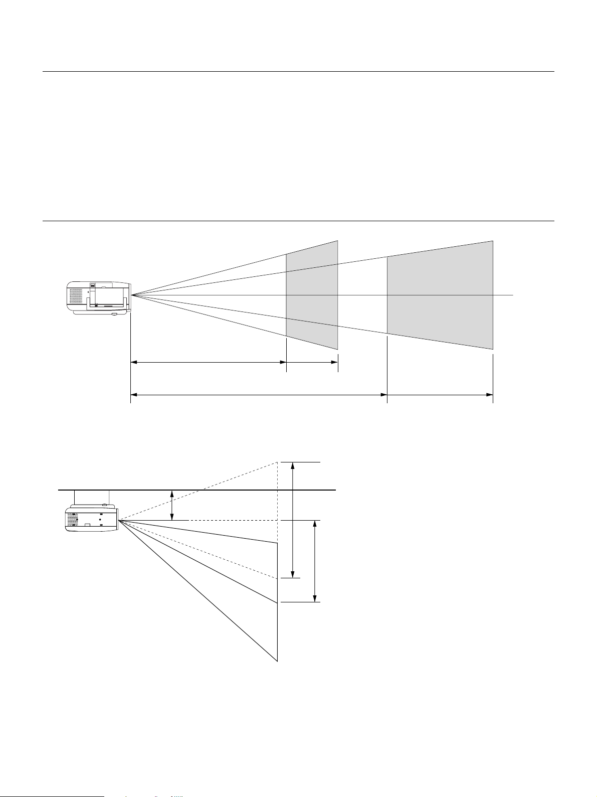
Selecting a Location
The further your projector is from the screen or wall, the larger the
image. The minimum size the image can be is approximately 25" (0.64
m) measured diagonally when the projector is roughly 3.9 feet (1.2 m)
from the wall or screen. The largest the image can be is 300" (7.6 m)
when the projector is about 39.4 feet (12.0 m) from the wall or screen.
Ceiling Installation
174.9 mm (7”)
Long Zoom Lens (H3.4) – (H5.1)
1.0V
0.85V
E – 18
Page 19
If your projector is mounted on the ceiling and your image is upside
WARNING
• Installing your projector on the ceiling must be done by a qualified technician. Contact your NEC dealer for more information.
* Do not attempt to install the projector yourself.
• Only use your projector on a solid, level surface. If the projector
falls to the ground, you can be injured and the projector severely damaged.
• Do not use the projector where temperatures vary greatly. The
projector must be used at temperatures between 32˚F (0˚C)
and 95˚F (35˚C).
• Do not expose the projector to moisture, dust, or smoke. This
will harm the screen image.
• Ensure that you have adequate ventilation around your projector so heat can dissipate. Do not cover the vents on the side or
the front of the projector.
For screen sizes between 25" and 300" not indicated on the above table, use formulas below.
Height
Screen size (Diagonal)
Width
Projection Distance = Screen Width (H)Lens Magnification
Throw distance for Standard Lens (m/inch) =
Throw distance for Long Zoom Lens (m/inch) =
H2.0 through H2.4 (For H between 1.2 m/47 inch and 12.0 m/472 inch)
H3.4 through H5.1 (For H between 4.1 m/161 inch and 21.0 m/827 inch)
down, use the “Menu” and “Select” buttons on your projector cabinet or
▲▼ button on your remote control to correct the orientation. (See page
E-43.)
Reflecting the Image
Using a mirror to reflect your projector’s image enables you to enjoy a
much larger image. Contact your NEC dealer if you need a mirror. If
you’re using a mirror and your image is inverted, use the “Menu” and
“Select” buttons on your projector cabinet or ▲▼ buttons on your remote control to correct the orientation. (See page E-43.)
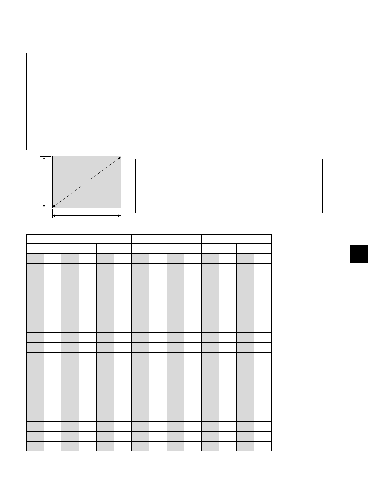
Screen and Projection Distance
Screen Size Standard Lens (2.0-2.4) Long Zoom Lens (3.4-5.1)
Diagonal Width Height Wide Tele Wide Tele
inch m inch m inch m inch m inch m inch m inch m
25
0.6
20
0.5
15
30
40
60
67
72
80
84
90
100
120
150
180
200
210
240
250
270
300
0.8
1.0
1.5
1.7
1.8
2.0
2.1
2.3
2.5
3.0
3.8
4.6
5.1
5.3
6.1
6.4
6.9
7.6
24
32
48
54
58
64
67
72
80
96
120
144
160
168
192
200
216
240
0.6
0.8
1.2
1.4
1.5
1.6
1.7
1.8
2.0
2.4
3.0
3.7
4.1
4.3
4.9
5.1
5.5
6.1
18
24
36
40
43
48
50
54
60
72
90
108
120
126
144
150
162
180
0.4
0.5
0.6
0.9
1.0
1.1
1.2
1.3
1.4
1.5
1.8
2.3
2.7
3.0
3.2
3.7
3.8
4.1
4.6
47
63
94
106
114
126
130
142
157
189
236
283
315
331
378
394
425
472
-
-
47
1.2
1.6
2.4
2.7
2.9
3.2
3.3
3.6
4.0
4.8
6.0
7.2
8.0
8.4
9.6
10.0
10.8
12.0
55
75
110
126
134
150
157
169
189
224
283
339
378
398
453
472
1.2
1.4
1.9
2.8
3.2
3.4
3.8
4.0
4.3
4.8
5.7
7.2
8.6
9.6
10.1
11.5
12.0
-
-
-
-
-
-
-
-
-
-
161
161
4.1
244
181
4.6
272
197
5.0
291
217
5.5
327
228
5.8
343
244
6.2
366
272
6.9
409
327
8.3
492
413
10.5
618
496
12.6
740
551
14.0
823
579
14.7
661
16.8
689
17.5
-
744
18.9
-
827
21.0
-
-
-
-
-
-
-
4.1
6.2
6.9
7.4
8.3
8.7
9.3
10.4
12.5
15.7
18.8
20.9
-
-
-
-
-
NOTE: Distances may vary +/-5%.
E – 19
Page 20
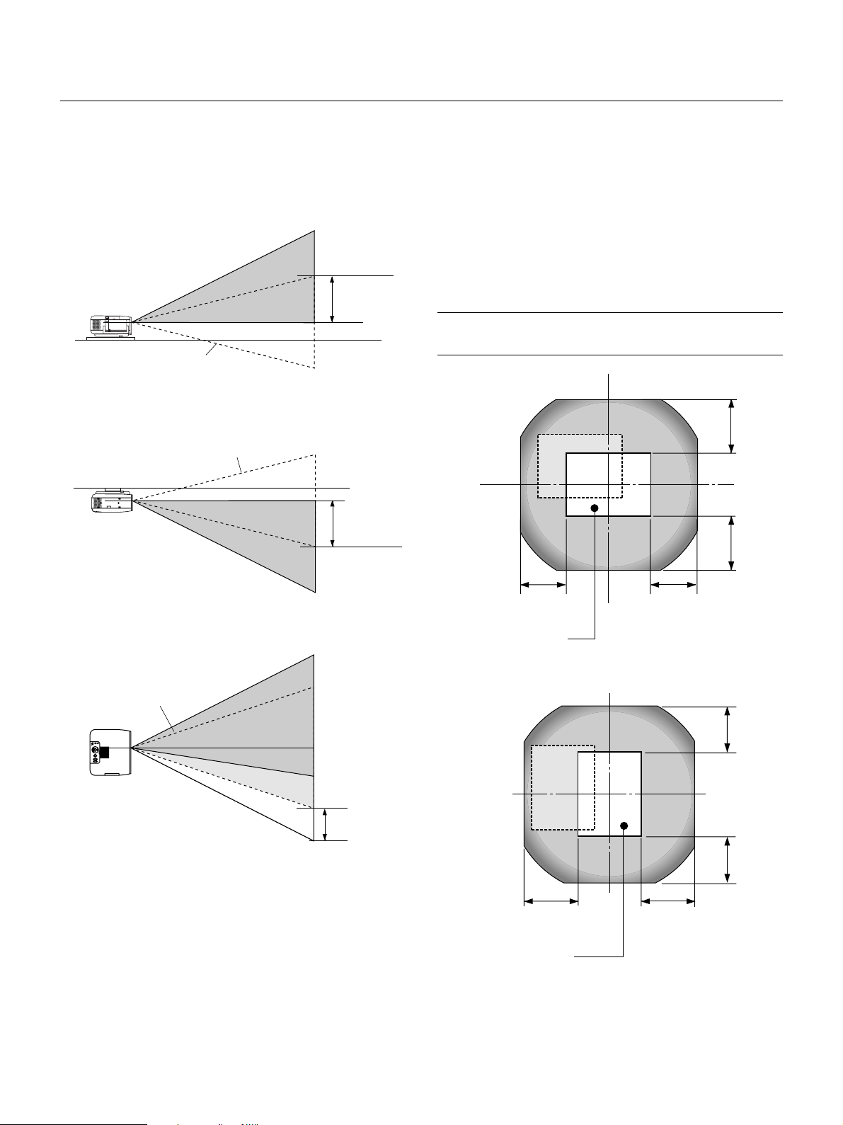
Lens Shift Adjustable Range
Lens Shift Range for Desktop and Ceiling Mount Application
The diagram below shows the location of the image position in the
lens. The lens can be shifted within the shaded area as shown using
the normal projection position as a starting point.
The lens can be returned to the default position (factory setting). See
“Zero Position” on page E-47.
Desktop/Front
Vertical
Ceiling/Front
Vertical
Normal position
Normal position
0.85V
0.85V
Maximum Possible Range:
Up: 0.85 V
Down: 0.85 V
Right: 0.55 H
Left: 0.55 H
(H: width of projected image, V: height of projected image)
NOTE: If lens is shifted in two directions combined, maximum range in either
direction cannot be obtained due to rounded off area near edge of lens. (example: shift up and right) See diagram below.
0.85V
0.85V
0.55H0.55H
Horizontal
AUTO
ADJUST
SOURCE
STATUS
POWER
ON/STAND BY
E
N
T
E
R
SELECT
M
E
N
C
U
A
N
C
E
L
LENS SHIFT
DOWN
UP
RIGHTLEFT
FOCUS
ZOOM
Normal position
Normal projection position
Por trait
0.55H
0.55H
0.55H
0.85V0.85V
Normal projection position
E – 20
Page 21

Wiring Diagram
PC with DVI output
Macintosh
(Desktop type or notebook type)
IBM VGA or Compatible
(Desktop type or notebook type)
DVI cable (not supplied)
Supplied signal cable
To mini D-Sub 15-pin connector on the projector. It is
recommended that you use a commercially available distribution
amplifier if connecting a signal cable longer than the supplied one.
Supplied mouse adapter (USB)
Supplied mouse adapter
Supplied serial cable
(For IBM PS/2 or USB)
Optional 15-pin-to-RCA
(female) x 3 cable
(ADP-CVI)
DVI IN
RGB IN
RGB OUT
PC CONTROL
MOUSE
OUTPUT
VIDEO
S-VIDEO
REMOTE
CONTROL
INPUT
L/
MONO
AUDIO IN
AUDIO IN
AUDIO OUT
AUDIO IN
AUDIO IN
AUDIO OUT
R
DVD Player
(with component output)
Monitor
Document Camera
To video, S-video, and audio
inputs on the projector.
NOTE: When using with a notebook PC, be sure to connect between the projector and the notebook PC before turning on the
power to the notebook PC. In most cases signal cannot be output from RGB output unless the notebook PC is turned on after
connecting with the projector.
NOTE: If using video, S-video, or audio cables, the cables should be 3 m (9.8 feet) or shorter.
Remote Control Guideline
1. Plug the supplied serial cable with the mouse output port of the projector into your computer’s mouse port
and restart your computer to gain remote mouse control.
2. When using the remote control’s built-in infrared mouse on a laptop computer, the laptop’s mouse, trackball
or trackpad will be disabled. Disconnect the serial cable from the mouse output port and restart your computer to regain trackball or trackpad mouse control.
3. If the screen goes blank while using your remote control, it may be the result of the computer’s screen-saver
or power management software.
4. If you accidentally hit the OFF button on the remote control, wait 2 full minutes and then press the ON button
to resume.
VCR, DVD Player or
LaserDisc Player
E – 21
Page 22

AUDIO IN
AUDIO IN
AUDIO OUT
DVI IN
RGB IN
RGB OUT
PC CONTROL
R
L/
MONO
VIDEO
Connecting Your PC or Macintosh Computer
IBM VGA or Compatibles (Notebook type)
or
Macintosh (Notebook type)
RGB signal cable (supplied)
To mini D-Sub 15-pin connector on the
projector. It is recommended that you use
a commercially available distribution
amplifier if connecting a signal cable
longer than the supplied one.
DVI IN
RGB IN
AUDIO IN
Audio cable
(not supplied)
IBM VGA or Compatibles (Desktop type)
Macintosh (Desktop type)
The new Macintosh computer such as
G3 will have the 15 pin HD connector. The GT950's "Plug and Play" data
will be downloaded to the Macintosh.
Therefore, a Mac adapter will not be
necessary.
AUDIO IN
Connecting your PC or Macintosh computer to your GT950 projector
will enable you to project your computer’s screen image for an impressive presentation.
To connect to a PC or Macintosh, simply:
1. Turn off the power to your projector and computer.
2. Use the signal cable that’s supplied to connect your PC or Macintosh
computer to the projector.
3. Turn on the projector and the computer.
4. If the projector goes blank after a period of inactivity, it may be caused
by a screen saver installed on the computer you’ve connected to the
projector.
For older Macintosh, use a commercially
available pin adapter to connect to your
Mac's video port.
P
I
D
456
N
O
3
2
1
Pin adapter for Macintosh
(not supplied)
E – 22
Page 23

PUT
AUDIO OUTPUT
AUDIO OUT
UTPUT
PC CONTROL
MOUSE
OUTPUT
REMOTE
CONTROL
INPUT
AUDIO IN
AUDIO IN
R
L/
MONO
VIDEO
S-VIDEO
Connecting Your Computer to the Mouse Output Port
IBM PS/2
MOUSE
OUTPUT
Mouse adapter
(For IBM PS/2)
(supplied)
Macintosh with USB
Port
Mouse adapter (USB)
(supplied)
The built-in remote mouse receiver enables you to operate your computer's mouse functions from the remote control. It
is a great convenience for clicking through your computer-generated presentations.
To connect the mouse output port:
1. Turn off your computer.
2. For PCs: Remove your current mouse and connect the supplied serial cable from the mouse output to your PC's
mouse port. (Use the 6-pin adapter for connecting to a PS/2 computer or the supplied USB adapter.)
For Macintosh: Attach the supplied mouse adapter for USB to the mouse output port's serial cable and connect the
projector to your USB port of a Macintosh computer.
3. When the built-in remote mouse receiver is available, it will disable your regular mouse, disconnect the serial cable
and restart your computer.
NOTE: The mouse adapter for USB is not compatible with the USB terminal on the projector.
E – 23
Serial cable (supplied)
Page 24

A
U
D
IO
IN
A
U
D
IO
IN
P
U
T
A
U
D
IO
O
U
T
DVI IN
RGB IN
RGB OUT
PC CONTROL
MOUSE
OUTPUT
REMOTE
CONTROL
INPUT
AUDIO IN
AUDIO IN
R
L/
M
ON
O
VIDEO
S-VIDEO
Connecting an External Monitor
AUDIO IN
AUDIO IN
AUDIO OUT
AUDIO OUT
DVI IN
RGB IN
RGB OUT
PC CONTROL
MOUSE
OUTPUT
REMOTE
CONTROL
INPUT
AUDIO IN
AUDIO IN
R
L/
MONO
VIDEO
S-VIDEO
Connecting a PC with DVI output
The DVI input accepts up to the XGA@60Hz signal.
External monitor
AUDIO
DVI IN
RGB Signal
cable
(supplied)
To RGB INPUT
RGB IN
RGB OUT
You can connect a separate, external monitor to your GT950 projector
to simultaneously view on a monitor the RGB analog, DVI analog, or
component image you're projecting. To do so:
1. Turn off the power to your projector, monitor and computer.
2. Use a 15-pin cable to connect your monitor to the RGB OUT (Mini
D-Sub 15 pin) connector on your projector.
3. Turn on the projector, monitor and the computer.
NOTE: The Auto Adjust feature does not work for DVI digital signal. When DVI
signal is selected and the image position is not corrected, adjust the horizontal
and vertical position using the Position/Clock screen. See page E-40 for more
details.
To DVI digital or
DVI analog
DVI cable (not supplied)
When Viewing a DVI Digital Signal:
To project a DVI digital signal, be sure to connect the PC and the projector using a DVI-D signal cable (not supplied) before turning on your
PC or projector. Failure to do so may not activate the digital output of
the graphics card resulting in no picture being displayed. Should this
happen, restart your PC.
Do not disconnect a DVI-D signal cable while the projector is running.
If the DVI-D signal cable has been disconnected and then re-connected,
an image may not be correctly displayed. Should this happen, restart
your PC.
NOTE:
* The RGB OUT connector outputs RGB signal during standby. When the pro-
jector goes into standby, the image on an external monitor disappears for a
moment.
* The DVI digital output signal from the RGB OUT connector is muted.
* When attaching two D-Sub connector cables to the RGB IN and the RGB
OUT connectors simultaneously, use a cable with connector sizes of 39 mm
x 16 mm (1.53" x 0.63")or less to keep the two connectors from making
contact with each other.
E – 24
Page 25

AUDIO IN
AUDIO IN
AUDIO OUT
D
VI-I IN
R
GB IN
RGB OUT
PC CO
NTRO
L
R
L/
MONO
VIDEO
Connecting Your DVD Player
AUDIO
R L
Red
Component
Y Cb Cr
DVD player
RGB IN
Audio cable
(not supplied)
White
Y
Cb
Component video cable
RCA3 (not supplied)
AUDIO
R L
Red
Cr
Optional 15-pin-to-RCA (female)3 cable
(ADP-CV1)
Audio Equipment
White
You can connect your projector to a DVD player with component outputs or Video output. To do so, simply:
1. Turn off the power to your projector and DVD player.
2. If your DVD player has the component video (Y,Cb,Cr) output, use a
commercially available component video cable (RCA3) and the
optional 15-pin-to-RCA (female)3 cable to connect your DVD player
to the RGB INPUT connector on the projector.
For a DVD player without component video (Y,Cb,Cr) outputs, use
common RCA cables (not provided) to connect a composite VIDEO
output of the DVD player to the Video Input of the projector.
3. Turn on the projector and DVD player.
NOTE: Refer to your DVD player’s owner’s manual for more information about
your DVD player’s video output requirements,
E – 25
Page 26

IN
AUDIO IN
AUDIO OUT
AUDIO OUT
NPUT
RGB OUTPUT
PC CONTROL
MOUSE
OUTPUT
REMOTE
CONTROL
INPUT
AUDIO IN
AUDIO IN
R
L/
M
O
N
O
VIDEO
S-VIDEO
Connecting Your VCR or Laser Disc Player
VCR/ Laser disc player
S-VIDEO
S-VIDEO
VIDEO
AUDIO IN
Audio equipment
AUDIO OUT
R L
Audio cable (not supplied)
AUDIO IN
R L
S-video cable (not supplied)
AUDIO IN
AUDIO OUT
Video cable (not supplied)
VIDEO
Document camera
Use common RCA cables (not provided) to connect your VCR, laser disc player or document camera to your projector.
To make these connections, simply:
1. Turn off the power to the projector and VCR, laser disc player or document camera.
2. Connect one end of your RCA cable to the video output connector on the back of your VCR or laser disc player, connect the other end to the Video
input on your projector. Use an audio cable (not supplied) to connect the audio from your VCR or laser disc player to your audio equipment (if your
VCR or laser disc player has this capability). Be careful to keep your right and left channel connections correct for stereo sound.
3. Turn on the projector and the VCR or laser disc player.
NOTE: Refer to your VCR or laser disc player owner’s manual for more information about your equipment’s video output requirements.
E – 26
Page 27

S
S
U
TO
AD
AUDIO INPU
AUDIO INPU
AUDIO OUTP
AUDIO OUTPUT
DVI-I INPUT
RGB INPUT
RGB OUTPUT
PC CONTROL
MOUSE
OUTPUT
REMOTE
CONTROL
INPUT
AUDIO INPUT
AUDIO INPUT
R
L/
MONO
VIDEO
S-VIDEO
3. OPERATION
This section describes how to select a computer or video source, how to adjust the picture, and how to customize the menu or projector settings.
Connecting the Power Cable and Turning on the Projector
Before you turn on your projector, ensure that the computer or video source is turned on and that your lens hood cap is removed.
1. Connect the supplied power cable to the projector.
Plug the supplied power cable in the wall outlet. The projector will go into its standby mode and the power indicator will glow orange.
JU
ST
S
TA
P
T
O
U
W
S
O
E
N
R
/S
TA
N
D
B
Y
AC IN
M
E
N
U
S
ELE
E
N
CT
T
E
R
C
A
N
C
L
E
LENS SHIFT
FO
C
U
S
ZO
O
M
2. Turn on and off the Projector.
To turn on the projector:
Only after you press the "ON/STAND BY" button on the projector cabinet or "POWER ON" button on the remote control will the power
indicator turn to green and the projector become ready to use.
NOTE: To turn the projector on by plugging in the power cable, use the menu and enable the "Auto Start" feature. (See page E-45.)
NOTE: Immediately after turning on the projector, screen flicker may occur. This is not a fault. Wait 3 to 5 minutes until the lamp lighting is stabilized.
Status of Indicators:
Stand by
Steady orange light
OFF
S-VIDEO RGB1 RGB2
VIDEO
AUTO ADJ.
STATUS
POWER
ON
POWER
LASER
N
E
U
M
SELECT
Lamp Mode:
Normal mode
OFF ON
POWER
Lamp Mode:
Eco mode
Power "ON/STAND BY" button
Indicators
STATUS
Steady light
Flashing green light
Steady green light
Flashing 3 minutes.
During this time Normal mode is
forcefully selected.
POWER
STATUS
POWER
E – 27
AUTO
ADJUST
STATUS
POWER
ON/STAND BY
Steady green light
Steady green light
E
N
T
E
R
SOURCE
C
A
SELECT
N
C
E
M
E
L
STATUS
POWER
N
U
LEN
Page 28

To turn off the projector:
First press the Power (ON/STANDBY) button on the projector cabinet or the POWER OFF button on the remote control for a minimum of two
seconds. The power indicator will glow orange. After the projector turns off, the cooling fans keep operating for 2 minutes.
NOTE: Do not disconnect the power cable during this time.
Then, unplug the power cable. The power indicator will go out.
Status of Indicators: OFF
OFF ON
POWER
Fan running
Flashing green
light
STATUS
POWER
Steady orange
light
Stand by
STATUS
POWER
About Startup Screen
(Menu Language Select screen)
When you first turn on the projector, you will get the Startup screen.
This screen gives you the opportunity to select one of the seven menu languages: English, German, French, Italian, Spanish,Swedish and Japanese.
To select a menu language, follow these steps:
1. Use the Select ▲ or ▼ button to select one of the seven languages for the menu.
N
E
U
M
SELECT
E
N
T
E
R
L
E
C
N
A
C
2. Press the Enter button to execute the selection.
N
E
U
M
SELECT
E
N
T
E
R
L
E
C
N
A
C
3. The Basic/Custom menu will be displayed in the language you have selected.
SELECT
E
N
T
E
R
L
E
C
N
A
C
OFF
VIDEO
S-VIDEO RGB1 RGB2
AUTO ADJ.
SELECT
E
N
T
E
R
FOCUS ZOOM
HELP
KEYSTONE
FREEZE
PIC-MUTE
POWER
N
E
U
M
PJ
POINTER
MAGNIFY
VOLUME
C
N
A
C
SHIFT
PC CARD
SLIDE
FOLDER
SLIDE
ON
LASER
L
E
To close the menu, press the Cancel button.
After this has been done, you can proceed to the advanced menu operation.
If you want, you can select the menu language later. See "Language" on page E-42.
E – 28
LIST
Page 29

Set up the projector
1. Turn on the projector
2. Select your type of projection:
Desktop front, ceiling rear, desktop rear, and ceiling front.
NOTE: In some cases the image may move down a little immediately after a
lens shift adjustment has been made in the downward direction.
(When a lens shift adjustment has been made in the upward direction, this
image movement will not occur)
(2) Press the ZOOM button to display the Zoom adjustment screen.
Use the Select / button on the remote control to adjust the image
size.
To close the Zoom adjustment screen, press the CANCEL button.
You can also adjust the image size by using the ZOOM + or –button on the
projector cabinet.
ZOOM
3. Select the Computer, Video Source or PC Card Viewer
Press a source button on the remote control or the projector cabinet to select “Video” (VCR, document camera, or laser disc
player), S-Video”, “RGB” (computer or DVD with component
output), “DVI DIGITAL/ANALOG” or “PC Card Viewer” to display the image.
Or press the “Menu” button on the remote control or the cabinet
and use the menu to select your video source: “Video”, “S-Video”,
“RGB”, “DVI DIGITAL/ANALOG”, or “PC Card Viewer”.
4. Adjust the image position and the image size.
(1) Press the SHIFT button to display the Lens Shift adjustment screen.
Use the Select button on the remote control to move the image horizontally, vertically or diagonally.
To close the Lens Shift adjustment screen, press the CANCEL button.
See page E-20 for “Lens Shift Adjustable Range”.
Projected image position can be shifted by using the LENS SHIFT button
on the cabinet.
Pressing two arrow buttons at the same time can move the lens diagonally.
SHIFT
ZOOM
(3) Press the FOCUS button to display the Focus adjustment screen.
Use the Select / button on the remote control to adjust the focus.
To close the Focus adjustment screen, press the CANCEL button.
You can also adjust the image size by using the FOCUS + or –button on
the projector cabinet.
FOCUS
FOCUS
SELECT
E – 29
Page 30

Other adjustments
A
U
D
IO
IN
A
U
D
IO
IN
A
U
D
IO
O
U
A
U
D
IO
O
U
T
DVI IN
RGB IN
RGB OUT
PC CONTROL
MOUSE
OUTPUT
REMOTE
CONTROL
INPUT
AUDIO IN
AUDIO IN
R
L/
MONO
VIDEO
S-VIDEO
Rotate the projector to make the
image square.
Each of the feet height can be changed up to 0.24” (6mm) or at angles
up to 1.8 degrees.
Use keystone correction for
proper adjustment.
Rotate the four feet to make the
image square to the screen.
Up
Down
E – 30
Page 31

Basic Operation
Selecting the computer or video source:
Adjust the Image Using Auto Adjust
The Auto Adjust function automatically optimizes the image in RGB or
DVI (DIGITAL / ANALOG) mode.
SOURCE
Each time the Source button is pressed, the input source will change
as follows:
→ RGB → Video → S-Video → DVI (DIGITAL)
PC Card Viewer ← DVI (ANALOG) ←
If no input signal is present, the input will be skipped.
VIDEO S-VIDEO RGB1 RGB2
PC CARD
Source display
AUTO ADJ.
[Poor picture]
[Normal picture]
Press the Auto Adjust button to fine-tune the computer image or to
remove any vertical banding that might appear and to reduce video
noise, dot interference or cross talk (this is evident when part of your
image appears to be shimmering). This function adjusts the clock frequencies that eliminate the horizontal banding in the image. This function also adjusts the clock phase to reduce video noise, dot interference or cross talk. (This is evident when part of your image appears to
be shimmering.)
This adjustment may be necessary when you connect your computer
for the first time.
NOTE: The Auto Adjust function does not work for component signal.
E – 31
Page 32

Volume control:
Sound level from the speaker and AUDIO OUTPUT mini jack on the
projector can be adjusted.
Sound is not available when PC Card Viewer is selected.
VOLUME
increase volume
Volume bar
decrease volume
Using Pointer
You can use one of eight pointers to draw your audience's attention to
the portion of a projected image you want.
POINTER
Press the Pointer button to
display the pointer.
Turning off picture and sound:
Press the Picture Mute button to turn off the image and sound for a
short period of time. Press again to restore the image and sound.
PIC-MUTE
Getting Help about how to operate the projector:
You get the contents about Help.
HELP
SELECT
Display Help
Exit Help
SELECT
Use the Select button to
move the pointer.
Enlarging and Moving a Picture
You can enlarge the area you want up to 400 percent.
To do so:
1. Press the Pointer button to display the pointer.
POINTER
2. Move the pointer to the area you want to enlarge.
SELECT
3. Enlarge the selected area.
When the Magnify (+) button is pressed, the pointer is changed to
a magnifying glass. To move the magnifying glass, use the Select
button.
MAGNIFY
E – 32
Page 33

4. Return the image to the original size.
MAGNIFY
Correcting Keystone distortion
Press (+) or (-) to correct keystone (trapezoidal) distortion to make the
top or bottom of the screen longer or shorter so that the projected
image is rectangular.
KEYSTONE
Keystone distortion Normal
Using the Menus
NOTE: The on-screen menu may not be displayed correctly while interlaced
motion video image is projected.
1. Press the “Menu” button on the remote control or projector cabinet to display the Main Menu.
NOTE: When using a USB mouse, click the mouse button to display the
main menu. For other operations, do the same way as you use your PC
mouse.
2. Press the ▲▼ buttons on the remote control or the projector cabi-
net to highlight the menu for the item you want to adjust or set.
3. Press the
or the remote control to select a submenu or item.
4. Adjust the level or turn the selected item on or off by using “Select”
screen slide bar will show you the amount of increase or decrease.
5. Changes are stored until you adjust it again.
ENTER ......... Stores the setting or adjustments.
CANCEL ..........
NOTE: You can close the main and sub menus simultaneously by pressing
the PJ button to cancel the Projector mode.
6. Repeat steps 2-5 to adjust an additional item, or press “Cancel”
on the projector cabinet or the remote control to quit the menu
display.
button or the “Enter” button on the projector cabinet
or buttons on the cabinet or the remote control. The on-
Return to the previous screen without storing settings or adjustments.
NOTE: The maximum keystone angle that can be corrected is 30 degrees upward and 30 degrees downward with the projector placed horizontally on the
ground plane.
Depending on the type of graphics being used, the picture may get blurred or
keystone correction may not be possible when excessive keystone correction
is used.
The idea is, the closer you are to native resolution, the better image you will
see.
In Portrait mode, correct the keystone so that the height at the left and right of
the screen may look the same.
Freezing a picture
Press the Freeze button to freeze a picture. Press again to resume
motion.
FREEZE
Customizing Basic/Custom Menu
The Basic/Custom menu can be customized to meet your requirements.
Selecting a menu item from the “Basic/Custom Menu Edit” list, allows
you to custom tailor the menu items to your needs.
1. Select “Basic/Custom Menu Edit” to display the “Basic/Custom
Menu Edit” screen.
E – 33
Page 34

2. Use the ▲ or ▼ button to highlight your selection and press the
Enter button to place a check mark next to an option. This action
enables that feature.
Press the Enter button again to clear the check box.
If you select an item with a solid triangle
and press the Enter
button on the remote control or the projector cabinet, you can
enable all the items within that submenu.
Also you can turn on an item within the submenu without placing
a check mark on the main menu item.
NOTE: Up to 12 main menu items (within Basic/Custom Menu Edit, not
including submenu items) can be selected.
An item “To Advanced Menu” will be added to the bottom of the Basic/
Custom Menu.
Selecting this item and pressing the “Enter” button will display the “Advanced Menu” features.
When a passcode is set for your projector, the Passcode input screen
will be displayed, See page E-48 for more information.
Using a USB Mouse
Using a USB mouse gives you a smooth operation. A commercially
available USB mouse is required.
NOTE: There may be some brands of USB mouse that the projector does not
support.
Operate the Menus using the USB mouse:
3. In order for the changes to take effect, use the or button on
the remote control or the projector cabinet to highlight “OK”,
then press the Enter button. To cancel the changes, use the ▲ or
▼ buttons to highlight “Cancel” and press the “Enter” button.
To return to the factory default, select “Reset” then press the “Enter” button.
The default Basic/Custom Menu items are:
Source Select [RGB, Video, S-Video, DVI (DIGITAL/ANALOG) and
PC Card Viewer], Picture, Volume, Image Options (Keystone, Lamp
Mode and Factory Default), Projector Options (Menu), Tools (Capture, PC Card Files and ChalkBoard) and Help (Contents and Information)
NOTE: Once you have selected OK on the Basic/Custom Menu Edit screen, you
cannot cancel the changes on the Menu screen. However, you can re-edit the
menu items over again as described in the steps above.
NOTE: If the “Advanced Menu” item has been selected on the Menu mode, you
get the “Confirmation Change Menu” upon completion of “Basic/Custom Menu”
editing. In this case, selecting “Yes” then “Enter” will close all the menus and
apply the changes from the Advanced menu to the Basic/Custom Menu. If you
select “No” then “Enter” functions, then all menu items will return to the Advanced menu, but your changes will still be available within the “Basic/Custom
Menu” selection. To display the previously tailored Basic/Custom Menu, select
“Basic/Custom Menu” from the “Menu Mode”.
Mouse Cursor:
When connecting a USB mouse to the projector, you get a mouse
cursor on the screen.
Unless you use your USB mouse within 10 seconds, the mouse
cursor disappears.
Menu Display:
Clicking with a mouse button displays the main menu.
Clicking displays the pull-down menu.
To close the menu, click anywhere in the background.
Adjusting and Setting Display:
You can select a menu item and click with a mouse button to make
adjustments and setting.
Examples:
Click (or press and hold) the mouse button or to adjust the
brightness.
Or click and drag the mouse button on the slide bar horizontally to
adjust it.
To save the adjustments, click . The display is closed.
If you click anywhere in the background while displaying adjustment and setting menu or dialog box, you will get the main menu at
the clicking point.
NOTE: The MOUSE OUTPUT port on the projector is not compatible with the
USB mouse.
E – 34
Page 35

Menu Tree
Advanced Menu
Source Select
Picture
Volume
Image Options
Color Management
Projector Options
Tools
Help
RGB
Video
S-Video
DVI (DIGITAL)
DVI (ANALOG)
PC Card Viewer
more
RGB (Video)
RGB (S-Video)
Keystone
Lamp Mode
Advanced Options
Factory Default
Color Temperature
Gamma Correction
Color Correction
Color Matrix
White Balance
Brightness / Contrast / Color / Hue / Sharpness
Volume
Normal / Eco
Aspect Ratio
Noise Reduction
Position / Clock
Resolution
Video Filter
Overscan
All Data / Current Signal
Normal / Natural 1 / Natural 2
Off / Mode 1 / Mode 2 / Mode 3 / sRGB / User 1 / User 2
Select Color Matrix HDTV / SDTV
Select Color Matrix Type B-Y / R-Y, Cb / Cr, Pb / Pr
Brightness R/G/B, Contrast R/G/B
Input Signal (1.33:1 / 1.78:1 / 1.85:1 / 2.35:1)
Display Area (1.33:1 / 1.78:1 / 1.85:1 / 2.35:1)
Off / Low / Medium / High
Horizontal / Vertical / Clock / Phase
Auto / Native
On / Off
0% / 5% / 10% / 25%
E – 35
Page 36

Advanced Menu
Source Select
Picture
Volume
Image Options
Color Management
Projector Options
Tools
Help
Sleep Timer
Menu
Setup
LAN Mode
Lens
Passcode
Capture
PC Card Files
ChalkBoard
Remaining Time, Preset Time (Off / 0:30 / 1:00 / 1:30 / 2:00)
Page 1
Page 2
Menu Mode (Advanced Menu, Basic/Custom Menu)
Basic/Custom Menu Edit
Language (English / German / French / Italian / Spanish / Swedish / Japanese)
Projector Pointer (Pointer 1-8)
Menu Display Time (Manual / Auto 5 sec / Auto 15 sec / Auto 45 sec)
Message Source (On / Off)
No Input (On / Off)
Clean Filter (On / Off)
Direct Button Volume Bar (On / Off)
Keystone Bar (On / Off)
Page 1
Page 2
Page 3
Page 4
Page 5
Page 6
Orientation (Desktop Front / Ceiling Rear / Desktop Rear / Ceiling Front)
Portrait (Auto / Off / On)
Background (Blue / Black / Logo)
Mouse Button (Right Hand / Left Hand)
Sensitivity (Fast / Medium / Slow)
PC Card Viewer Options Show Folder List
(Auto Play / Manual Play)
Interval (5 – 300 sec)
Capture Options (High Quality / Normal / High Compression)
Signal Select
RGB (Auto / RGB / Component / Scart)
Video (Auto / NTSC3.58 / NTSC4.43 / PAL / PAL-M / PAL-N / PAL60 / SECAM)
S-Video (Auto / NTSC3.58 / NTSC4.43 / PAL / PAL-M / PAL-N / PAL60 / SECAM)
DVI (ANALOG) (Auto / RGB / Component)
RGB (Video) (Auto / NTSC3.58 / NTSC4.43 / PAL / PAL-M / PAL-N / PAL60 / SECAM)
RGB (S-Video) (Auto / NTSC3.58 / NTSC4.43 / PAL / PAL-M / PAL-N / PAL60 / SECAM)
Auto Adjust
Auto Start
Power Management
Power Off Confirmation
Keystone Save
Continuous Operation
Built-in Speaker
Clear Lamp Hour Meter
Clear Filter Usage
Remote Sensor (Front / Back / Left / Right)
Control Panel Key Lock (Enable)
S-Video Mode Select (Off / S2)
Communication Speed (4800 / 9600 / 19200 / 38400)
Default Source Select (Last / Auto / Select)
(RGB / Video / S-Video / DVI (DIGITAL) / DVI (ANALOG) / PC Card Viewer/
RGB (Video) / RGB (S-Video))
Contents
Information
Shift (Adjustment), Speed (Normal / Fine), Zero Position
Entry
Delete
Contents
Page 1
Page 2
Page 3
Page 4
Source Name / Input Terminal / Entry No. / Horizontal Frequency /
Vertical Frequency / Sync Polarity
Signal Type / Video Type / Sync Type / Interlace
Remaining Lamp Time / Lamp Hour Meter / Filter Usage / Projector Usage
Version (BIOS / Firmware / Data / SUB-CPU)
E – 36
Page 37

Menu Elements
Title bar
Highlight
Tab
Help Button
Close Button
Radio button
OK Button
Cancel Button
Solid triangle
Check box
Drag
Tool bar
Slide bar
Menu windows or dialog boxes typically have the following elements:
Title bar: Indicates the menu title.
Highlight: Indicates the selected menu or item.
Solid triangle: Indicates further choices are available. A highlighted triangle indicates the item is active.
Tab: Indicates a group of features in a dialog box. Selecting on any tab brings its page to the front.
Radio button: Use this round button to select an option in a dialog box.
Check box: Place a checkmark in the square box to turn the option On.
Slide bar: Indicates settings or the direction of adjustment.
OK button: Press to confirm your setting. You will return to the previous menu.
Cancel button: Press to cancel your setting. You will return to the previous menu.
Close button: Click to close the window with saving changes. (USB mouse only)
Help button: Indicates that help about that feature is available (USB mouse only). Press the Help button on the remote control to display help.
Toolbar: Contains several icons for specific tasks. It is also referred to as "launcher".
Drag: Point the mouse here, and click and drag to move a toolbar.
E – 37
Page 38

Menu Descriptions & Functions
Source Select
Enables you to select a video source such as a VCR, DVD player, laser
disc player, computer or document camera depending on what is connected to your inputs.
Press the "Select" button on the projector cabinet or your remote control to highlight the menu for the item you want to adjust.
RGB / DVI (DIGITAL/ANALOG)
Selects the computer connected to your RGB (Analog/Digital) or component signal.
NOTE: An optional component cable (Component V cable) is needed for a component signal. Select "Component" from the Input Signal submenu to display
the component signal.
Video
Selects what is connected to your Video input-VCR, laser disc player,
DVD player or document camera.
PC Card Viewer
This feature enables you to make presentations using a PC card that contains
captured images and slides created with the exclusive PC Card Viewer Utility
contained in the CD-ROM1. See page E-52 for installing the PC Card Viewer
Utility. The starting screen for the PC Card Viewer varies depending on the
settings of the Setup's Page 2. See Setup on page E-44.
NOTE: Even if you switch the current PC Card Viewer source to another source,
the current slide is retained. When you return back to the PC Card Viewer, you
will get the slide that has been retained. A launcher will appear when you press
the MENU button.
Prev Play Jump Setup View
Drag
Next Stop Select Delete
S-Video
Selects what is connected to your S-Video input-VCR, DVD player, or
laser disc player.
NOTE: A frame may freeze for a brief period of time when a video is played back
in fast-forward or fast-rewind with a Video or S-Video source.
A press of the MENU button displays the toolbar; a press of the MENU
button again displays the Menu and hereafter each press of the MENU
button switches displaying between the Menu and the toolbar.
The launcher is a tool bar including the following buttons:
Drag ............. Drags to move the tool bar. (for USB mouse operation only)
Prev ............. Returns to the previous slide or folder.
Next ............. Advances to the next slide or folder.
Play .............. Plays back automatically or manually depending on the set-
ting on PC Card Viewer Options of the menu. This allows you
to move on to the next slide when "Manual Play" is selected.
Stop ............. Stops Auto Play while you are playing back and to resume
playing from the selected slide or folder when "Auto Play" is
selected.
Jump ........... Displays a list of slides while you are playing back.
Select ........... Displays a list of folders while you are playing back.
Setup ........... Displays the PC Card Viewer Options dialog box on Page 2 of
the Setup dialog box.
Delete ........... Deletes a captured slide(s) or all the captured slides in the
selected folder.
View ............. Hides the tool bar while you are playing back. Clicking with
the right button of a mouse shows it again.
E – 38
Page 39

Picture (not available for PC Card Viewer)
Image Options
Provides access to controls for your image. Use ▲▼ buttons on the
projector cabinet or the remote control to highlight the menu for the
item you want to adjust.
Brightness ... Adjusts the brightness level or the back raster intensity.
Contrast ....... Adjusts the intensity of the image according to the incoming
signal.
Color ............ Increases or decreases the color saturation level (not valid
for RGB).
Hue .............. Varies the color level from +/- green to +/-blue. The red level
is used as reference. This adjustment is only valid for Video
and Component inputs (not valid for RGB).
Sharpness .... Controls the detail of the image for Video (Not valid for RGB
and Component).
Volume (not available for PC Card Viewer)
Adjusts the sound level of the projector.
NOTE: You can also display the volume bar without opening the menu. See
"Volume Bar (Direct Button)"on page E-43 for more details.
Keystone
This feature corrects the keystone (trapezoidal) distortion to make
the top of the screen longer or shorter to be the same as the bottom.
Use the or buttons on the slide bar to correct the keystone
(trapezoidal) distortion.
In Portrait mode, correct the keystone so that the height at the left and
right of the screen may look the same.
Keystone distortion Normal
NOTE: The maximum keystone angle that can be corrected is 30 degrees upward and 30 degrees downward with the projector placed horizontally on the
ground plane.
Depending on the type of graphics being used, the picture may get
blurred or keystone correction may not be possible when excessive
keystone correction is used.
The idea is, the closer you are to native resolution, the better image
you will see.
Lamp Mode
This feature enables you to select two brightness mode of the lamp:
Normal and Eco modes. The lamp life can be extended up to 2000
hours by using the Eco mode.
Normal Mode ..............This is the default setting.
Eco Mode ....................Select this mode to increase the lamp life.
NOTE: If you have selected the Eco mode, the lamp lights in Normal mode for 3
minutes after the projector is turned on. After 3 minutes the lamp will change to
Eco mode.
E – 39
Page 40

Aspect Ratio
(not available for RGB, DVI digital and PC Card Viewer)
See "Auto Adjust” on page E-45 for turning on or off the Auto Adjust
feature.
Use "Phase" only after the "Clock" is complete.
This adjustment is made automatically when the Auto Adjust is turned
on.
Resolution (when Auto Adjust is off)
You can select the aspect ratio for input signal and display area respectively.
Select the appropriate aspect ratio using the Select , , ▲, or ▼
button.
NOTE: When "Resolution" is set to "Native", this feature is not available, and the
stored settings and adjustments are invalid.
The screen size (width-to-height) is set for input signal and display area respectively.
In Portrait mode, the screen size means height-to-width.
Noise Reduction (not available for RGB, DVI digital and PC
Card Viewer)
You can select three levels video noise reduction.
NOTE: The lower the Noise Reduction level, the better the image quality by way
of higher video bandwidth.
Position/ Clock (when Auto Adjust is off)
This allows you to activate or deactivate the Advanced AccuBlend feature.
Auto ............. Turns on the Advanced AccuBlend feature. The projector au-
tomatically reduces or enlarges the current image to fit the
full screen.
Native ........... Turns off the Advanced AccuBlend feature. The projector dis-
plays the current image in its true resolution.
See "Auto Adjust” on page E-45 for turning on or off the Auto Adjust
feature.
NOTE: While you are displaying an image with higher resolution than the
projector's native resolution, even when you are in the Native mode, the image
is displayed full screen using the Advanced AccuBlend feature.
Video Filter (when Auto Adjust is off)
This function reduces video noise.
On ................ The low-pass filter is applied.
Off ................ The filter is removed.
Screen adjustments are possible even when the filter is On.
Overscan (RGB and DVI digital only)
This allows you to manually adjust the image horizontally and vertically, and adjust Clock and Phase.
Horizontal/Vertical Position
.................... Adjusts the image location horizontally and vertically using
the and buttons.
This adjustment is made automatically when the Auto Adjust
is turned on.
NOTE: In Portrait mode, the H-Position and V-Position work in reverse.
Clock ............ Use this item to fine tune the computer image or to remove
any vertical banding that might appear. This function adjusts
the clock frequencies that eliminate the horizontal banding in
the image.
Press the and buttons until the banding disappears.
This adjustment may be necessary when you connect your
computer for the first time. This adjustment is made automatically when the Auto Adjust is turned on.
Phase ........... Use this item to adjust the clock phase or to reduce video
noise, dot interference or cross talk. (This is evident when
part of your image appears to be shimmering.) Use the
and buttons to adjust the image.
You can select overscan percentage for RGB signal.
Select the appropriate option using the Select or button.
NOTE: When "Resolution" is set to "Native", this feature is not available, and the
stored settings and adjustments are invalid.
E – 40
Page 41

Factory Default
Changes all adjustments and setting to the factory preset for each
source individually except Remaining Lamp Time, Lamp Hour Meter,
Filter Usage, Projector Usage, Language, Communication Speed and
Passcode. (To reset the lamp usage time, see "Clear Lamp Hour Meter"
on page E-45.)
Color Correction
All Data ............... Reset all the adjustments and settings for all the signals
to the factory preset.
Current Signal ..... Resets the adjustments for the current signal to the fac-
tory preset levels.
All the items in ”Picture”, ”Advanced Options” and “Color Management”
can be reset.
NOTE: The Volume, Keystone, Lamp Mode and all the items in the Projector
Options can be reset only when "All Data" is selected.
Color Management
Color Temperature
This option allows you to adjust neutral tint for yellow, cyan or magenta.
There are 4 factory presets optimized for various types of images, or
you can set 2 user adjustable settings.
Color Correction
OFF .............. Turns off the Color Correction. You obtain the brightest im-
age.
Mode 1 ........ Recommended for true flesh tones
Mode 2 ........ Recommended for turf color
Mode 3 ........ Recommended for deep red
sRGB ........... Standard color values
User 1 .......... User adjustable
User 2 .......... User adjustable
When selecting User 1 or 2, the submenu below will be displayed.
You can customize each color or tint.
Color Correction (User Adjust)
Color Tune ... Adjusts the Tint on whole screen for RGB.
Yellow .......... Adjusts yellow to obtain reddish yellow or greenish yellow
Magenta ....... Adjusts magenta or purple to obtain reddish magenta or blu-
ish magenta.
Cyan ............. Adjusts cyan or light greenish blue to obtain greenish or blu-
ish cyan.
White
(On/Off) ....... Select "ON" for a bright white image; "OFF" for a natural white
image.
This feature adjusts the color temperature using the slide bar.
Move the slide bar to the right to increase the color temperature for a
bluish image; to the left to decrease it for a reddish image.
Gamma Correction
Use the or button to choose "Normal" when in a lighted room and
"Natural 1&2" when in a darkened room. "Natural 1" for better flesh
tone; "Natural 2" for true reproduction of middle tones.
Each mode is recommended for :
Normal ......... For the regular picture
Natural 1 ...... For true color reproduction of natural tones
Natural 2 ...... For dark portions of a picture
Color Matrix (available for component video and HDTV signal
only)
First select an appropriate color matrix to fit your component signal for
HDTV or SDTV. Then select an appropriate matrix type from B-Y/R-Y,
Cb/Cr or Pb/Pr.
E – 41
Page 42
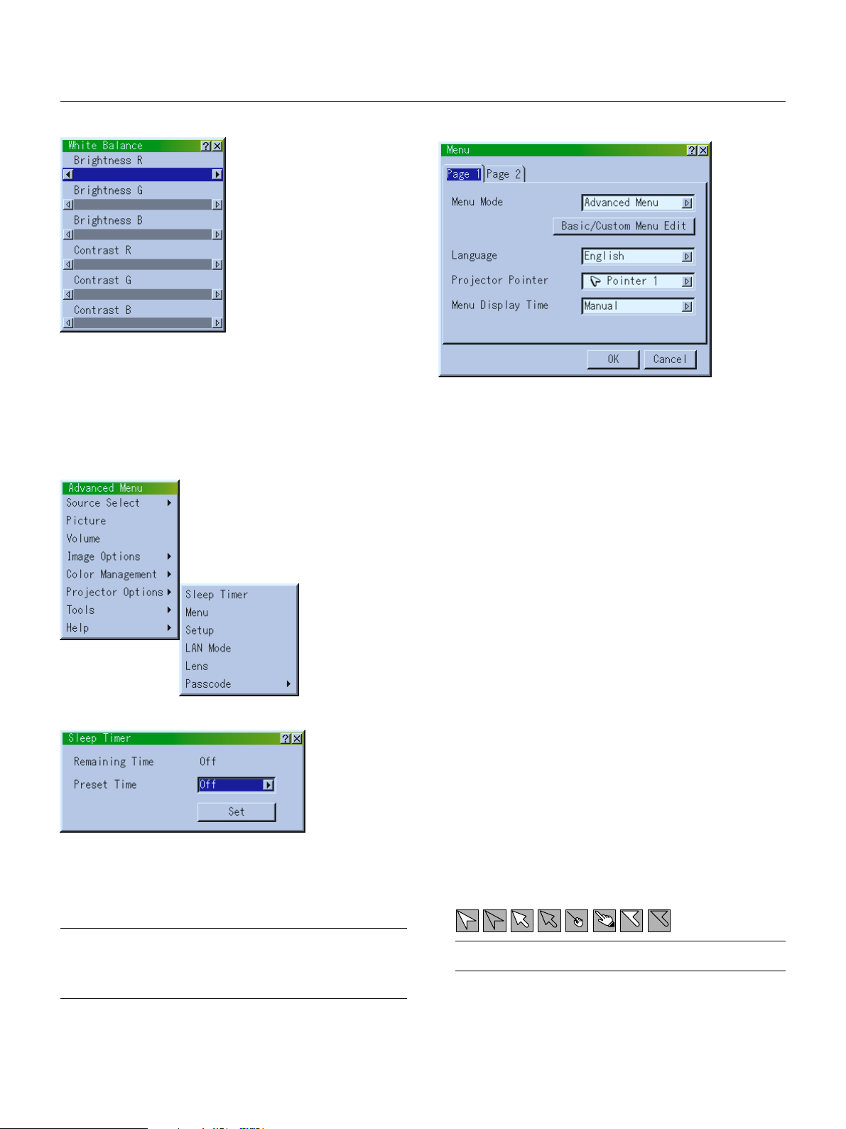
White Balance
This allows you to adjust the white balance. Brightness for each color
(RGB)is used to adjust the black level of the screen;
Contrast for each color (RGB)to adjust the white level of the screen.
First use the ▲ or ▼ buttons to select R, G, or B for the brightness and
the contrast. Next use the or buttons to adjust the level.
Menu
Allows you to set preferences for the on-screen menu.
Press “OK” to save your changes for all the features of page 1 and
page 2.
Projector Options
Sleep Timer
1. Select your desired time between 30 minutes and 2 hours in 30
minute increments.
2. Select Set and press the ENTER button on the remote control.
3. The remaining time starts counting down.
4. The projector will turn off after the countdown is complete.
[Page 1]
Menu Mode:
This feature allows you to select two menu modes: Advanced Menu
and Basic/Custom Menu.
* When a passcode is set for your projector, changing the menu from Basic
to Advanced will display the Passcode input screen. See page E-48 for
more information.
Advanced Menu .......... This is the menu that contains all the available menus
and commands.
Basic/Custom Menu .... This is the menu that you can customize using the
Basic/Custom Menu Edit to fit your needs.
The factory default Basic/Custom menu includes:
Source Select (RGB, Video, S-Video, DVI (DIGITAL/ANALOG) and
PC Card Viewer), Picture, Volume, Image Options (Keystone, Lamp
Mode and Factory Default), Projector Options (Menu), Tools (Capture, PC Card Files and ChalkBoad) and Help (Contents and Information). See page E-33 for instructions about how to customize the
Basic/Custom Menu.
Language:
You can choose one of seven languages for on-screen instructions.
The options are: English, German, French, Italian, Spanish, Swedish and Japanese.
Projector Pointer:
This enables you to select from eight different Pointer icons for the
"Pointer" button on your remote control.
After moving your Pointer icon to the area you want on the screen,
press the Magnify button on the remote control to enlarge the selected area on the screen. See page E-32 for more details.
NOTE:
•To cancel the preset time, set “Off” for the preset time or turn off the power.
• When the remaining time reaches 3 minutes before the projector is turned
off, the “Projector will turn off in 3 minutes” message will be displayed on
the bottom of the screen.
E – 42
NOTE: There may be cases where the Pointer function is not available (ex. a
non-interlace signal at 15kHz such as video game.)
Page 43

Menu Display Time :
This option allows you to select how long the projector waits after
the last touch of a button to turn off the menu.
The preset choices are "Manual", "Auto 5 sec", "Auto 15 sec", and
"Auto 45 sec". The "Auto 45 sec" is the factory preset.
Manual ......... The menu can be turned off manually.
Auto 5 sec .... The menu will automatically be turned off in 5 seconds if no
buttons are pressed within 5 seconds.
Auto 15 sec.. The menu will automatically be turned off in 15 seconds if no
buttons are pressed within 15 seconds.
Auto 45 sec.. The menu will automatically be turned off in 45 seconds if no
buttons are pressed within 45 seconds.
NOTE: If no buttons on the remote control are pressed within 10 seconds, the
PJ button’s light goes out to indicate that you are in the Computer mode. To
enable the projector menu operation again, press the PJ button again to light
red.
[Page2]
Keystone Bar: This option turns on or off the keystone bar when you adjust the keystone using KEYSTONE +/– button on the remote control.
On ................ You can increase or decrease the level with the keystone bar
on screen.
Off ................ You can increase or decrease the level without having to use
the keystone bar.
Setup
Enables you to set operating options.
Press "OK" to save your changes for all the features of Page1, Page2,
Page3, Page 4, Page5 and Page6.
[Page1]
Message:
You can choose the desired information to be displayed on the
screen.
On ................ The message will be displayed.
Off ................ The message will not be displayed.
Source: You can turn on and off the information for input name
such as VIDEO and RGB.
When this option is on, the current input will be displayed each time
you switch sources or turn on the projector.
No Input: This option turns on or off the "No Input" message to be
displayed in the top right corner on the screen.
Clean Filter: This option turns on or off the "Please clean the filters" message each time you turn on the projector if the projector
has been used in excess of 100 hours of use.
To reset the filter usage, see page E-45.
Direct Button:
Volume Bar: This option turns on or off the volume bar when you adjust
the sound volume using VOL+/– button on the remote control.
On ................ You can increase or decrease the sound volume with the vol-
ume bar on screen.
Off ................ You can increase or decrease the sound volume without hav-
ing to use the volume bar.
Orientation:
This reorients your image for your type of projection.
The options are: desktop front projection, ceiling rear projection,
desktop rear projection, and ceiling front projection.
Por trait:
This feature sets the menu orientation. The options are: Auto, Off
and On.
Auto ............. Automatically selects the setting "Portrait" or "Landscape" ap-
propriate for the projector orientation.
Off ................ Setting for the landscape orientation.
NOTE: Be sure not to select this option when using the projector in the
portrait orientation because the temperature control setting will vary depending upon between the portrait or landscape setting.
On ................ Setting for the portrait orientation.
Background:
Use this feature to display a blue/ black screen or logo when no
signal is available. The default background is NEC logo. You can
change the logo screen using the PC Card Files feature. See page
E-49.
The background logo feature does not support Portrait display.
Mouse Settings:
This option lets you to change your USB mouse settings. The mouse
settings feature is available for USB mouse only. Choose the settings you want:
Mouse Button ............. "Right Hand" or "Left Hand"
Mouse Sensitivity ......."Fast", "Medium" or "Slow"
E – 43
Page 44

[Page2] PC Card Viewer Options [Page3] Signal Select
Show Folder List:
If this option is checked, when PC Card Viewer input is selected on
the projector, the folder lists will be displayed and allows you to
select the presentation from a PC card.
Auto Play:
If this option is checked, any given slide will start to play automatically.
Auto Play Interval:
You can specify interval time between 5 and 300 seconds.
NOTE: The Auto Play Interval time set on the PC Card Viewer Utility overrides the one set here.
Manual Play:
Views a slide manually when PC Card Viewer input is selected.
NOTE: The Auto Play and Manual Play options determine the behavior of
the Play/Stop [ / ] icon on the Viewer toolbar.
NOTE: If you check "Auto Play" and select "PC Card Viewer" on the projector,
the slides will automatically start to play back from any given slide.
Capture Options: (available for JPEG only)
These options are used for the Capture function that you can select
from Tools. You have three options for JPEG compression quality:
High quality, Normal and High Compression.
High Quality .................... Gives quality of JPEG a priority.
Normal ............................ Gives normal JPEG quality.
High Compression .......... Gives compression a priority.
RGB and DVI (ANALOG):
Allows you to choose "RGB" for an RGB source such as a computer, or "Component" for a component video source such as a
DVD player. Normally select "Auto" and the projector automatically
detects a component signal. However there may be some component signals that the projector is unable to detect. If this is the case,
select "Component". Select “Scart” for the European Scart.
VIDEO and S-VIDEO:
This feature enables you to select composite video standards manually. Normally select "Auto".
Select the video standard from the pull-down menu.
This must be done for Video and S-Video separately.
RGB (Video/S-Video):
Allows you to choose "Video" or "S-Video" for RGB connector.
Normally select "Auto".
E – 44
Page 45

[Page4]
Auto Adjust:
When "Auto Adjust" is set to "On", the projector automatically determines the best resolution for the current RGB input signal to
project an image using NEC's Advanced AccuBlend Intelligent Pixel
Blending Technology.
The image can be automatically adjusted for position and stability;
"Horizontal Position", "Vertical Position", "Clock" and "Phase".
Built-in Speaker:
This option allows you to active the built-in speakers when you connect an audio cable to the AUDIO OUT terminal.
Clear Lamp Hour Meter:
Resets the lamp clock back to zero. Pressing this button appears a
confirmation dialog box. To reset the lamp usage hour, press "OK".
NOTE: The projector will turn off and go into standby mode after 1600 hours
(up to 2100 hours in Eco mode) of service. If this happens, press the "Help"
button on the remote control for ten seconds to reset the lamp clock back
to zero. Do this only after replacing the lamp.
Clear Filter Usage:
Resets the filter usage back to zero. Pressing this button appears a
confirmation dialog box. To reset the filter usage hour, press "OK".
[Page5]
On ................ Automatically adjusts image "Horizontal Position", "Vertical
Position", "Clock" and "Phase".
Off ................ User can adjust the image display functions ("Horizontal Po-
sition", "Vertical Position", "Clock" and "Phase") manually.
Auto Start:
Tu rns the projector on automatically when the power cable is inserted into an active power outlet. This eliminates the need to always use the "Power" button on the remote control or projector cabinet.
Power Management:
When this option is on and there is no RGB input for five minutes or
more, the projector will automatically turn itself off.
Power Off Confirmation:
This option determines whether a confirmation dialog for turning off
the projector will appear or not.
NOTE: When the confirmation message is displayed, you must be in the
Projector mode to operate your projector using the remote control. If not,
press the PJ button on the remote control to change your projector to the
Projector mode. The button lights to indicate that you are in the Projector
mode.
Keystone Save:
This option enables you to save your current keystone settings.
Saving your change once affects all sources. The changes are saved
when you turn off the projector.
Continuous Operation:
This option allows the cooling fans to run at a high speed in the Eco
mode.
When you wish to cool down the temperature inside the projector in
the Eco mode, check this box.
Remote Sensor:
This option determines which remote sensors on the projector are
enabled in wireless mode.
The options are: front, rear, right, or left. All checked boxes indicate
that they can accept the infrared signal from the supplied remote
control.
Control Panel Key Lock:
This option turns on or off the Control Panel Key Lock function.
NOTE:
* This Control Panel Key Lock does not affect the remote control and the
PC Control functions.
* When the cabinet buttons are disabled, pressing and holding the CAN-
CEL button for about 10 seconds will change the setting from "disabled"
to "enabled".
S-Video Mode Select:
This feature is used to select the S-Video signal detection mode.
This allows identifying of the S-Video signals with different aspect
ratio (Zoom signal 16:9, Wide Zoom signal 4:3).
S2 ............... Identifies Zoom or Wide Zoom signal.
OFF ............. Does not identify any S-video signal.
On: ............... Runs the cooling fans at a higher speed than normal opera-
tion.
NOTE: Be sure to select the Eco mode when turning on this option.
Off:.............. Sets the cooling fan speed appropriate for the temperature
inside the projector.
E – 45
Page 46

[Page6]
Communication Speed:
This feature sets the baud rate of the PC Control port (Mini DIN 8
Pin).
It supports data rates from 4800 to 38400 bps.
The default is 38400 bps. Select the appropriate baud rate for your
equipment to be connected.
Default Source Select:
You can set the projector to default to any one of its inputs each
time the projector is turned on.
Last .............. Sets the projector to default to the previous or last active
input each time the projector is turned on.
Auto ............. Searches for an active source in order of RGB → Video → S-
Video → DVI (DIGITAL) → DVI (ANALOG) → PC Card Viewer
→ RGB and displays the first found source.
Select ........... Displays the selected source input every time the projector is
started up. Select an input from the pull-down menu.
LAN Mode
Please consult with your network administrator about these settings.
[IP Address]
An IP address can be automatically assigned to this projector by your
DHCP server. If your network does not automatically assign IP address, ask your network administrator for an address, and then register it manually.
Automatic: Automatically assigns an IP address to the projector
from a DHCP server.
NOTE: The Automaic function is under development. Register it manually.
Manual: Provides a space for you to register the IP address or
subnet mask number obtained from your network administrator.
IP Address ......... Register your IP address.
Subnet Mask ...... Register your subnet mask number.
[Port, Gateway]
E – 46
Port:
This sets the TCP port number for connection using the control
software. Please be careful not to duplicate another TCP port on
PC that runs the control software.
Gateway:
Checking this box will make the set default route valid.
When data is sent from the LAN card, the transfer location will be
searched according to the previously set routing information;
however, when the transfer location has not been found as a result
of the search, the data will be sent to the device that holds the IP
address set here.
The IP address that is set here must be one that can be identified
by a search of the routing information.
Page 47

[Status]
Lens
Displays the status of the LAN settings.
IP Address ......... Indicates the IP address of the projector.
Subnet Mask ...... Indicates the subnet mask of the projector.
MAC Address ..... Indicates the MAC address of the LAN card.
After setting Shift, Speed, and Zero Position, select [OK] and press the
ENTER button.
To cancel, select [Cancel] and press the ENTER button.
Shift:
This option adjusts the image position.
Pressing the Adjustment button displays the Lens Shift adjustment
screen.
Use the Select buttons (, , ▲, ▼ ) to shift the image horizontally,
vertically, or diagonally.
To move the image diagonally, use two Select buttons simultaneously.
Example: To move the image in the upper right-hand corner of the
screen, press the Select ▲ and buttons at the same time.
Speed:
This option selects two speed modes for lens shift.
Normal: This is the default setting that allows the lens shift motor to
run fast.
Fine: This is the fine-adjustment setting that allows the lens shift
motor to run slowly.
Zero Position:
Returns the lens position to the default setting.
Select [Zero Position] and press the ENTER button. Next select
[OK] and press the ENTER button.
To cancel, select [CANCEL] and press the ENTER button.
Within lens shift adjustment, Zero position movement has an error of
1.5% (20 mm/0.8 inches in 60" screen).
E – 47
Page 48

Passcode
A passcode can be set for your projector to avoid operation by an unauthorized user using the Advanced Menu. When a passcode is set,
changing the menu from Basic to Advanced will display the Passcode
input screen.
To register your passcode:
4. Press the Select button four times and then press the Enter button.
The “Delete Passcode / Are you sure?” message will be displayed.
Use the Select
button. Your passcode has been deleted.
or button to select “Yes” and press the Enter
1. Select [Entry] and press the ENTER button. The [Entry] screen will
be displayed.
2. Type in a 4-digit combination of Select buttons (, , ▲, ▼ ) and
press the ENTER button.
The [Confirm Passcode] screen will be displayed.
3. Type in the same combination of Select buttons (, , ▲, ▼ ) and
press the ENTER button.
Your passcode has been assigned.
Tools
Provides tools for capturing images, displaying files in a PC Card and
drawing.
NOTE: The "Capture" and "PC Card Files" features are required for a PC card.
Capture:
Allows you to capture an image from a source that is currently being displayed. The image is saved as JPEG in the PC card.
When you select Capture from the menu, you will get a tool bar. You
can capture an image directly using the tool bar when the menu is
not displayed.
Capture
Drag
Freeze
Exit
To delete your passcode:
1. Select [Delete] and press the ENTER button. The [Delete] screen
will be displayed.
2. Type in your 4-digit passcode and press the ENTER button.
Your passcode has been deleted.
In case you forget your passcode, follow the steps below to delete it.
1. Select the Advanced menu from the Basic/Custom menu. The
Passcode entry screen will be displayed.
2. Press the Select ▲ button four times and then press the Enter but-
ton.
The “Warning Passcode!!” message will be displayed.
3. Press the Select ▼ button four times and then press the Enter but-
ton.
The “Warning Passcode!!” message will be displayed.
The tool bar includes the following buttons:
Drag ............. Drags to move the tool bar. (for USB mouse operation only)
Capture ........ Captures an image and save it as a JPEG file in a PC card.
Freeze .......... Freezes and unfreezes images.
Exit ............... Exits the Capture function.
Unless a PC card is inserted into the PC Card slot of the projector,
the Capture feature is not available.
The "Card Error" display means that the free space of the PC card
is insufficient for saving images. Make more space available on the
card by erasing unwanted images with your PC. The number of
images that can be captured depends on the size of the PC card.
NOTE: Be sure not to turn off the power or remove the PC card while capturing an image. Doing so could cause a loss of the data in the PC card or
damage to the card itself.
NOTE: Captured images with higher resolution than the projector's native
resolution cannot be displayed correctly.
E – 48
Page 49

PC Card Files:
Displays a list of all the files stored in the PC card so that you can
select a file you want to display. You can also sort files by file name
or date, or display the file.
Although a list of all the files in the PC card is displayed, you can
view files in idx, text, HTML, JPEG and BMP format only.
Selecting BMP and JPEG files automatically switches to the PC
Card Viewer source.
NOTE: When an image with a resolution of XGA (1024768) or higher is
projected, the PC Card Files screen may not be correctly displayed.
Changing Background Logo:
The Logo button allows you to select a background logo from graphic
files on a PC card and change to it as the background logo.
NOTE: File size must be 64KB or less. Other file formats than JPEG and
BMP are not available.
1. Use the ▲ or ▼ button to select a JPEG or BMP file for your back-
ground logo.
2. Use the and then ▼ button to select “Logo”.
Selecting "Execute" displays the file you selected.
When you select a JPEG or BMP file and press the Enter button on
the remote or the cabinet, or “Execute” on the above, you will get a
toolbar. This toolbar is used to return to the PC Card Files screen.
Drag
Return
Drag ............. Drags to move the tool bar. (for USB mouse operation only)
Return .......... Returns to the PC Card Files screen.
Close ............ Close the toolbar.
Close
3. Press the Enter on the remote control or the cabinet. You will get the
confirmation dialog box.
4. Select “OK” and press the Enter button. This completes changing a
logo for the background.
* Once you have changed the background from the NEC logo to another,
you cannot return the logo to background even by using Factory Default. To do so, repeat the above steps. The NEC logo file is included
on the supplied CD-ROM (/logo/nec_b_x.jpg).
E – 49
Page 50

ChalkBoard: (available only when using with USB mouse)
Provides the tool bar for producing freehand drawings.
Help
Pen
Drag
Drag ............. Drags to move the tool bar. (for USB mouse operation only)
Pen .............. Left-click and drag to draw. Left-click [▲] or right-click the
pen icon to display the pen palette containing four lines of
different thickness from which you can select a line you prefer by left-clicking.
Color ............ Selects a color. Left-click to display the color palette from
which you can select a color you prefer by left-clicking.
Eraser .......... Left-click and drag to erase part of a drawing. Left-click [▲]
or right-click the eraser icon to display the eraser palette containing four eraser of different thickness from which you can
select an eraser you prefer by left-clicking.
Clear ............ Left-click to clear the drawing completely from the ChalkBoard
screen.
View ............. Hides the tool bar by left-clicking. Right-clicking anywhere
on the screen displays the ChalkBoard tool bar again.
Exit ............... Clears the complete drawing and exits the ChalkBoard.
Eraser View
Exit
ClearColor
NOTE:
* The ChalkBoard feature is available only when a USB mouse is used. Free-
hand drawings cannot be saved or captured.
* The menu is not available while you display the ChalkBoard screen.
* The Capture function is not available on ChalkBoard screen.
* Switching slides clears a drawing completely.
Contents:
Provides an online help about how to use the menus. An underlined link means that you can move to an adjustment item directly.
Selecting the underlined link and pressing ENTER moves to the
corresponding adjustment item.
NOTE: The Help Menu may not be displayed correctly when a UXGA signal
is displayed.
Information:
Displays the status of the current signal, and the lamp and the projector usage hours.
This dialog box has four pages.
The information included are as follows:
NOTE: The progress indicator shows the percentage of remaining bulb life. The
value informs you of the amount of lamp and projector usage respectively.
[Page 1]
Source Name
Input Terminal
Entry No.
Horizontal Frequency
Ver tical Frequency
Sync Polarity
[Page 3]
Remaining Lamp Time (%)*
Lamp Hour Meter (H)
Filter Usage (H)
Projector Usage (H)
[Page 2]
Signal Type
Video Type
Sync Type
Interlace
* When the remaining lamp time reaches 0, the Remaining Lamp Time
bar indicator changes from 0% to 100 Hours and starts counting
down. If the remaining lamp time reaches 0 hours, the projector will
not turn on regardless of whether the lamp mode is Normal or Eco.
[Page 4]
Version
BIOS
Firmware
Data
SUB-CPU
E – 50
Page 51

Using the PC Card Viewer function
USB
NOTE: When using the supplied software (CD-ROM1)
The software is designed to use with a personal computer only. Do not play the
software on CD player. Doing so could cause damage to speakers.
Ejecting the PC Card
Press the eject button. The PC card pops out a little. Grasp the edges
of the PC card and pull it out. Do not eject the PC card while its data is
being accessed.
Features
The Viewer feature allows slides stored on a PC memory card (referred to as PC card in this manual) to be displayed on the projector.
Even if no computer is available, presentations can be conducted simply with the projector. This feature is convenient for holding presentations at meetings and in offices, as well as for playing images taken on
digital cameras.
Easy to use
• Presentations can be started immediately simply by inserting a PC
card (not supplied)
• Easy slide switching
• Remote control operation
•Jumping to list of slides or any specific slide
High quality images
• High resolution up to 1024768 dots
• 24-bit full color playback
• Viewing of digital camera images
Simple utility software (for computer)
• PC Card Viewer Utility operable on Windows 95 / 98 / Me / NT4.0
(SP3 or later) / 2000
• Slides can be created by capturing the currently displayed image
• Control screen for displaying lists of slides and editing
• PC Card Viewer PPT Converter 1.0 [Add-In Version] converts files
created with Microsoft PowerPoint 95/97/2000 (hereafter referred to
as PowerPoint) into indexes playable with PC Card Viewer
* Microsoft, Windows and PowerPoint are registered trademarks of
Microsoft Corporation.
Eject button
Direction for Inserting the PC Card
The PC card has a top and bottom and must be inserted into the
PC card slot in a specific direction. It cannot be inserted backwards
or upside-down. Attempting to force it into the slot in the wrong
direction may break the internal pin and damage the card slot.
Refer to the PC card's operating instructions for the proper direction of insertion.
PC Card Type
The PC Card slot accepts PCMCIA Type II only.
Inserting and Ejecting a PC Card
A PC card is used to view presentation data prepared on the computer
and to capture and play images projected with the projector.
Inserting the PC Card
• Hold the PC card horizontally and insert it slowly into the card slot
with its top facing up.
• The eject button pops out once the PC card is fully inserted.
Check that the PC card is fully inserted.
NOTE: Do not try to force the PC card into the slot.
USB
E – 51
Page 52

Installing the PC Card Viewer Software
Before Installing
Perform the following before installing the PC Card Viewer software:
• If Windows is already started, exit all applications. Installation may
not be performed properly if any applications are running.
Installation
Install the viewer software as described below.
To quit installation before it is completed, press the "Cancel" button
then follow the instructions in the dialog box.
1. Start up Windows.
2. Insert the CD-ROM into the CD-ROM drive.
The auto CD play function automatically starts the CD-ROM's
program and the contents screen appears.
Starting Up the PC Card Viewer Software
on your PC
(PC Card Viewer Utility 1.0)
Use the PC Card Viewer Utility 1.0 for creating viewer slides.
To start the PC Card Viewer software:
* Select [Start]-[Programs]-[NEC Projector Tools]-[PC Card Viewer
Utility 1.0].
Refer to online help for instructions on using the PC Card Viewer software.
* The auto CD play function operates if the "Auto insert notification" box in
the computer's CD-ROM control panel is checked. (The box is checked
by default.)
3. Click [Installing the PC Card Viewer Utility 1.0]
The setup dialog appears.
* Follow the instructions in the setup dialog to complete the installation.
For instructions on uninstalling the PC Card Viewer software, see page
E-56.
Contents of the English version PC Card Viewer software
(PC Card Viewer Utility 1.0)
This is the software used for creating PC Card Viewer slides. In this
manual it is referred to as the "PC Card Viewer software".
PC Card Viewer PPT Converter 1.0
This is an application that converts files created with Microsoft
PowerPoint 95/97/2000 into indexes so that they can be played directly
with the PC Card Viewer Utility 1.0.
PC Card Viewer PPT Converter is installed automatically when you
install the PC Card Viewer Utility.
To start PC Card Viewer PPT Converter:
* Select PC Card Viewer PPT Converter from NEC Projector Tools.
Basic Operation of the PC Card Viewer Software
PC Card Viewer Utility is an application for editing documents, converting them into slides and storing them on PC cards as playback
data (indexes) for presentations using projectors.
E – 52
Page 53

Operating the PC Card Viewer Function
from the Projector (playback)
Jump ......... Displays a list of slides while you are playing back.
Select ........ Displays a list of folders while you are playing back.
This section describes the operation for showing slides of presentation
documents created using the PC Card Viewer function with the projector.
It is also possible to make slides directly from the images projected
with the projector.
Projecting slides
1. Insert a PC card into the card slot.
Insert the PC card with the side with the insertion direction arrow
on the top.
* Press the eject button to eject the card.
2. Select the “PC Card Viewer” from the Source Select menu.
3. Project slides.
Checking “Show Folder List”, means that selecting PC Card Viewer
input displays a list of the folders in the PC card and if “Auto Play” is
checked the projector automatically starts to play slides at the first
slide of the folder you have selected.
A tool bar will appear when you press the MENU button on the remote
control or the projector cabinet or clicking with the right button of a
mouse.
Setup ........ Displays the PC Card Viewer Options dialog box on Page 2 of
Delete ........ Deletes a captured slide(s) or all the captured slides in the
View .......... Hides the tool bar while you are playing back. Pressing the
NOTE: If no PC card is inserted in the PC CARD slot, there is no signal, and a
black, blue or logo background is displayed, depending on the setting.
Playback is stopped when SLIDE +/– on the remote control or /
button on the cabinet is pressed in Auto Play mode.
NOTE: Up to 12 indexes can be displayed on the list of folders. The folder in the
right bottom is always a folder exclusively for captured images, but is only
displayed when images have been captured. To display the list of folders when
there are 13 or more indexes stored on the PC card, select "Edit index" from the
PC Card Viewer software's "File" menu and move the index you want to display
to within 12 indexes from the top of the folder index. For details on indexes,
refer to the PC Card Viewer software's help folder.
the Setup dialog box.
Capture – specific folder.
MENU button or clicking with the right button of a mouse
shows it again.
Prev Play Jump Setup View
Drag
Next Stop Select Delete
The tool bar includes the following buttons:
Drag .......... Drags to move the tool bar (for USB mouse operation only).
Prev .......... Returns to the previous slide or folder. Or this lets you play
Next .......... Advances to the next slide or folder. Or this lets you play
Play ........... Plays back automatically or manually depending on the set-
Stop .......... This allows you to stop Auto Play while you are playing back
slides back in reverse.
slides back.
ting on PC Card Viewer Options of the menu. This allows you
to move on to the next slide when “Manual Play” is selected.
and to resume playing from the selected slide or folder when
“Auto Play” is selected.
E – 53
Page 54

When the tool bar is not displayed:
M
E
N
U
E
N
T
E
R
C
A
N
C
E
L
PJ
FOCUS ZOOM
OFF
VIDEO
AUTO ADJ.
S-VIDEO RGB1 RGB2
LASER
ON
VOLUME
SHIFT
HELP
POINTER
KEYSTONE
MAGNIFY
FREEZE
PIC-MUTE
PC CARD
SLIDE
FOLDER
SLIDE
LIST
SELECT
POWER
Press the FOLDER LIST button on the remote control to display folders from a PC card in the projector’s PC Card slot.
Multi cursor (blue marks)
Folder
SLIDE
Current folder number
02 : 0001 / 0008
Current slide number
Folder Folder Folder
Folder
Number of all slides
in folder
Use the SLIDE +/- button to
advance to the next folder or
return to the previous folder.
Folder
Slide(Table) cursor (green marks)
Auto Play Mode
• If the “Auto Play” option is selected in “PC Card Viewer Options” of
the menu, any given slide will start to play automatically. You can
also specify Auto Play Interval between 5 and 300 seconds.
Switching to Slides Directly from Other Input
Modes
With this function it is possible to switch directly to a slide when the
picture of a VCR or computer is being projected.
Example:
When conducting presentations using a combination of slides and
moving pictures from a VCR, etc., it is possible to switch from a PC
Card Viewer slide to the video picture then back to the PC Card Viewer
slide simply by using a source button and PC CARD button.
NOTE: Even if you switch the current PC Card Viewer source to another source,
the current slide is retained. When you return back to the PC Card Viewer, you
will get the slide that has been retained.
Use the SLIDE +/- button to
advance to the next slide or return to the previous slide.
NOTE: You can also use the and button on the remote control to select
folders or slides.
If you use the and button on the remote control for PC Card Viewer operation, press the PJ button to switch to the Projector mode and the PJ button
lights red.
E
N
T
E
SELECT
R
Slide Slide Slide Slide
Slide Slide Slide Slide
02 : 0004 / 0008
Slide
Works as the Select button
on the projector.
L
E
C
N
A
C
PJ
NOTE: The PC card editing operation cannot be performed from the projector.
Do so using the PC Card Viewer software.
FOCUS ZOOM SHIFT
Lit red
E – 54
Page 55

Capturing Images Displayed on the Projector
Deleting Captured Images
Storing images displayed on the projector on the PC card
Preparations:
Insert the PC card into the card slot.
Insert the PC card with the side with the insertion direction arrow on
the top.
* Press the eject button to eject the card.
1. Project the image you wish to store on the projector.
2. Select the “Capture” from the Tools menu.
Capture
Drag
3. A tool bar will appear.
The tool bar includes the following buttons:
Drag ............. Drags to move the tool bar (for USB mouse operation only).
Capture ........ Captures an image and save it as a JPEG file in a PC card.
Freeze .......... Freezes and unfreezes images.
Exit ............... Exits the Capture function. Another option to exit the Capture
function is to press MENU or CANCEL button on the remote
control or projector cabinet.
Freeze
Exit
Prev Play Jump Setup View
Drag
Next Stop Select Delete
Using the Delete button on the tool bar for PC Card Viewer can delete
captured images.
To delete captured images:
1. Select PC Card Viewer.
2. Use
button to select the Capture folder in the right bottom of
the screen.
3. Press the MENU button to display the tool bar.
4. Use the
or button to select the Delete icon and press the
ENTER button or click with a mouse button.
Viewing Digital Images
Digital images can be played with the PC Card Viewer if the following
conditions are met:
• If the image can be stored on an MS-DOS format PC card
• If the image can be stored in a format supported by the PC Card
Viewer.
With the PC Card Viewer, images on the card are searched for in
directories and images in JPEG or BMP format are recognized as
slides.
Searchable directories are directories within two steps from the root
directory, and searchable images are images within the first 12 files
in the directory. Only file and slide switching are possible.
NOTE: You can compress a captured file (JPEG) using the Capture Options in
the Setup dialog. See page E-44.
NOTE: Captured images with higher resolution than the projector's native resolution cannot be displayed correctly.
NOTE:
• File size of the captured image varies depending on the resolution of an
input signal.
• Since an image data is compressed with the JPEG format, the image is slightly
degraded.
NOTE: An hourglass indicating that an image is being captured appears on the
projector's display. Do not eject the PC card or turn off the projector's power
while this icon is displayed. Doing so will damage the PC card data. If the PC
card data is damaged, use a computer to repair the data.
NOTE: The folder in the right bottom is always a folder exclusively for captured
images. To display the list of folders when there are 13 or more indexes stored
on the PC card, select "Edit index" from the PC Card Viewer software's "File"
menu and move the index you want to display to within 12 indexes from the top
of the folder index. For details on indexes, refer to the PC Card Viewer software's
help file.
NOTE: The maximum number of images recognized as slides within one directory is 128.
E – 55
Page 56

Uninstalling the PC Card Viewer Software
Even if you do now know the PC Card Viewer software's file names or
where they are stored, the PC Card Viewer software files can be easily
removed from the system using the "Install/Uninstall Applications" control panel in Windows. (Normally there is no need to perform this operation.)
Uninstalling the software
Use the procedure described below to uninstall the PC Card Viewer
software files.
1. From the "Start" menu, select "Settings" then "Control Panels".
3. In the "Add/Remove Programs Properties" dialog box, click the
"Setup/Remove" tab, then select "PC Card Viewer Utility 1.0" from
the list of applications and click on "Add/Remove".
4. In the "Confirm File Deletion" dialog box, click "Yes".
2. In the "Control Panels" dialog box, double-click on "Add/Remove
Programs".
5. Once the application is uninstalled, click on "OK" in the "Remove
Program From Your Computer" dialog box.
E – 56
Page 57

Terminology
PC card
ATA card
CompactFlash
TYPE (I, II and III)
BMP
JPEG
This is the name of a card currently being standardized by the Japan Electronic Industry Association (JEIDA) and PCMCIA
(Personal Computer Memory Card Interface Association) of the United States.
A type of PC card. ATA was originally a type of interface between computers and fixed disk devices. The ATA card is a standard
card-type recording medium.
CompactFlash card is a small removable card conforming to ATA specifications. It is one-fourth the volume of a PCMCIA card.
PCMCIA 2.1 PC cards are divided into three types according to their thickness: Type I (3.3 mm), Type II (5.0 mm) and Type III
(10.5 mm).
A type of image format. The standard Windows Bit Map format used for MS-DOS/Windows-compatible computers.
A type of image format. "JPEG" is the abbreviation of Joint Photographic Experts Group. JPEG compression offers efficient
data storage. The data not required for displaying the image is identified and deleted. Since the data is deleted, JPEG
algorithms are said to be irreversible. This means that once the image is compressed, the decompressed image it is not the
same as the original image.
E – 57
Page 58

4. MAINTENANCE
This section describes the simple maintenance procedures you should
follow to replace the lamp and clean the filter.
Replacing the Lamp
After your lamp has been operating for 1500 hours (2000 hours : Eco
mode) or longer, the “Status” light in the cabinet will go on and the
message will appear. Even though the lamp may still be working, replace it at 1500 (2000 hours : Eco mode) hours to maintain optimal
projector performance.
CAUTION
• DO NOT TOUCH THE LAMP immediately after it has been used. It will
be extremely hot. Turn the projector off, wait 2 minutes, and then disconnect the power cable. Allow at least one hour for the lamp to cool
before handling.
• DO NOT REMOVE ANY SCREWS except the lamp cover screw and two
lamp housing screws. You could receive an electric shock.
• The projector will turn off and go into stand by mode after 1600 (2100
hours : Eco mode) hours of service. If this happens, be sure to replace
the lamp. If you continue to use the lamp after 1500 hours (2000 hours
: Eco mode) of use, the lamp bulb may shatter, and pieces of glass may
be scattered in the lamp housing. Do not touch them as the pieces of
glass may cause injury. If this happens, contact your NEC dealer for
lamp replacement.
To replace the lamp:
1. Loosen the lamp cover screw until the screwdriver goes into a
freewheeling condition and remove the lamp cover. The lamp cover
screw is not removable.
3. Insert a new lamp housing until the lamp housing is plugged into
the socket.
CAUTION: Do not use a lamp other than the NEC replacement lamp
(GT95LP). Order this from your NEC dealer.
Secure it in place with the two screws.
Be sure to tighten the screws.
4. Reattach the lamp cover.
Tighten the lamp cover screw.
Be sure to tighten the screw.
2. Loosen the two screws securing the lamp housing until the screwdriver goes into a freewheeling condition. The two screws are not
removable.
Remove the lamp housing by pulling out the handle.
NOTE: There is an interlock on this case to prevent the risk of electrical
shock. Do not attempt to circumvent this interlock.
5. After you install a new lamp, select [Projector Options] →
[Setup]→[Page 4]→[Clear Lamp Hour Meter] to reset the lamp
usage hours.
NOTE: When the lamp exceeds 1600 hours (2100 hours : Eco mode) of service, the projector cannot turn on and the message is not displayed. If this
happens, press the Help button on the remote control for a minimum of 10
seconds while in standby mode. When the lamp time clock is reset to zero, the
STATUS indicator goes out.
E – 58
Page 59

Cleaning or Replacing the Filters
The air-filter sponge keeps the inside of the GT950 Projector free from
dust or dirt and should be cleaned after every 100 hours of operation
(more often in dusty conditions). If the filter is dirty or clogged, your
projector may overheat.
CAUTION
•Turn off the power and unplug the projector before replacing the filter.
• Only clean the outside of the filter cover with a vacuum cleaner.
• Do not attempt to operate the projector without a filter cover.
•Your projector will not operate unless the filter cover is installed correctly.
To clean the air-filter:
Vacuum the filter-through the filter cover.
O
N/STAND BY
POW
STA
ER
TUS
ADJUST
AUTO
N
E
T
E
R
SOURCE
C
A
N
SELEC
C
E
L
T
M
E
N
U
L
DOW
E
F
T
N
LENS SHIFT
FO
CUS
UP
R
I
G
H
T
ZO
OM
To replace the air-filter:
1. Remove the filter cover by pushing up on the catch of the cover
until you feel it detach.
SOURCE
AUTO
STATUS
POWER
ON/STAND BY
ADJUST
M
E
N
U
SELECT
E
N
T
E
R
C
A
N
C
L
E
LENS SHIFT
+
+
–
FOCUS
–
ZOOM
When “Clean Filter” option is turned on, the “Please clean the filters”
message will be displayed each time the projector is turned on after it
has been used in excess of 100 hours. Should this message appear,
clean the filters.
• The message can be turned on or off using the [Projector Options]→
[Menu]→[Page 2]→[Message · Clean Filter]. See page E-43.
• After cleaning the filters and resetting the filter usage time back to
zero, the message will not be displayed.
See page E-45 for resetting the filter usage time.
2. Reinstall the new filter cover.
NOTE: Do not detach the sponge from the filter cover. Do not wash the filter
cover with soap and water. Soap and water will damage the the filter membrane. Before replacing the filter cover, remove dust and dirt from the projector cabinet. Keep out dust and during filter replacement.
E – 59
Page 60

5. TROUBLESHOOTING
This section helps you resolve problems you may encounter while setting up or using the projector.
Power/ Status Light Messages
Condition
Standby
Cooling down
Lamp in Normal mode
Lamp in Eco mode
3 minutes after lamp is turned on in
Eco mode
Lamp has reached its end of life
(Normal: 1500 hours or over)
(Eco: 2000 hours or over)
Lamp life has reached its end of life
(Normal: 1600 hours or over)
(Eco: 2100 hours or over)
Lamp or filter cover error (3 locations)
Temperature error
Fan error
Lamp error
Power Indicator Status Indicator
Steady orange
Blinking green
Steady green
Steady green
Steady green
Steady green
Steady orange
Steady orange
Steady orange
Steady orange
Steady orange
Common Problems & Solutions
Problem Check These Items
Does not turn on
No picture
Image isn’t square to the
screen
Picture is blurred
Image is scrolling vertically,
horizontally or both
Remote control does not
work
Status indicator is lit or blinking
Cross color in RGB mode
• Check that the power cable is plugged in and that the power button on the projector cabinet or the remote
control is on.
• Ensure that the lamp cover is installed correctly. See page E-58.
• Check to see if the projector has overheated or the lamp usage exceeds 1600 hours (2100 hours in Eco
mode). If there is insufficient ventilation around the projector or if the room where you’re presenting is particularly warm, move the projector to a cooler location.
• Use the menu to select your source (Video, S-Video, RGB, DVI (DIGITAL or ANALOG) or PC Card Viewer).
See page E-38.
• Ensure your cables are connected properly.
• Use menus to adjust the brightness and contrast. See page E-39.
• Remove the lens hood cap.
• Reset the settings or adjustments to factory preset levels using the Factory Default on the Image Options
Menu in Advanced menu. See page E-41.
• Reposition the projector to improve its angle to the screen. See page E-30.
• Use the Keystone to correct the trapezoid distortion. See page E-33 or 39.
• Adjust the focus. See page E-29.
• Reposition the projector to improve its angle to the screen. See page E-30.
• Ensure that the distance between the projector and screen is within the adjustment range of the lens. See
page E-19.
• Use menus or a source button on the remote control or the cabinet to select the source you want to input.
• Install new batteries. See page E-16.
• Make sure there are no obstacles between you and the projector.
• Stand within 22 feet (7 m) of the projector. See page E-16.
• Make sure that you are in the Projector mode or the PJ button lights in red. If not, press the PJ button.
• See the Power/ Status Light messages above.
• If Auto Adjust is off, turn it on. If Auto Adjust is on, turn it off and balance the image with the Position and Clock
Adjust on the Advanced Options Menu. See page E-40.
–
–
–
Steady green
Blinking green
Steady red (Normal mode)/
Steady orange (Eco mode)
Steady red
Blinking red (1 sec interval)
Blinking red (4 sec interval)
Blinking red (8 sec interval)
Blinking red (12 sec interval)
Note
–
Blinks green for 2 minutes
–
–
Fixed at Normal mode. Lamp mode can
be changed on the menu
Message appears on screen during 1500-1600
hours (Eco: 2000-2100 hours) of lamp usage.
The projector reaches its end of life. Please
replace the lamp as soon as possible.
The projector is in standby mode and cannot be turned on.
The projector is in standby mode and cannot be turned on.
The projector is in standby mode and cannot be turned on.
The projector is in standby mode and cannot be turned on.
The projector is in standby mode and cannot be turned on.
E – 60
Page 61

When using the PC Card Viewer function
Condition Status
No picture
• Is “PC Card Viewer” selected from the Source menu?
• Is the PC card seated in the PC CARD slot completely?
• Are slide data stored in the PC card?
•Have the contents of the PC card been destroyed?
Part of a slide is not displayed
Contents of PC Card are
damaged
For more information contact your dealer.
• While an image with over 1024768 dots is projected, several lines of information will be lost. Use the
supplied software change the image to 1024768 dots in size.
• Use a computer, etc., to repair the data.
E – 61
Page 62

6. SPECIFICATIONS
This section provides technical information about the GT950 Projector’s performance.
Model Number GT950
Optical
LCD Panel 0.9” p-Si TFT active-matrix with Micro Lens Array 1024768 dots
Lens Motorized zoom, motorized focus, motorized lens shift
F2.0 – 2.6 f=36.7 – 44.0 mm
Lamp 200W NSH lamp (160W in Eco mode)
The lamp, under normal operating conditions, is warranted for 1500 hours of operation time within 6 months.
Image Size 25 – 300 inches (635 – 7620 mm) diagonal
Projection Distance 3.9 – 39.4 ft (1.2 - 12.0 m)
Electrical
Inputs Video (NTSC / PAL / PAL-M / PAL-N / PAL60 / SECAM / NTSC4.43)
Horizontal Frequency : 15 – 100 kHz
Ver tical Frequency : 48 – 120 Hz
Video Bandwidth RGB: 80 MHz
Color Reproduction Full color, 16.7 million colors simultaneously.
Horizontal Resolution 550 TV lines : NTSC / PAL / PAL-M / PAL-N / NTSC4.43 / YCbCr
350 TV lines : SECAM
RGB: 1024 dots horizontal, 768 dots vertical
Power Requirement 100 – 120 / 200 – 240 VAC, 50 / 60 Hz
Input Current 3.4 A (100 – 120 VAC) / 1.7A (200 – 240 VAC)
Mechanical
Dimensions
Net Weight 15.9 lbs / 7.2 kg
Environmental Considerations
Regulations UL Approved (UL 1950, CSA 950)
14.3" (W)6.4" (H)12.7" (D) / 362mm (W)163mm (H)323mm (D) (not including lens and feet)
Operational Temperatures: 32˚ – 95˚F (0˚ to 35˚C), 20 – 80% humidity
Storage Temperatures: 14˚ – 122˚F (-10˚ to 50˚C), 20 – 80% humidity
Installation angle range: +/- 10°
Meets DOC Canada Class B requirements
Meets FCC Class B requirements
Meets AS/NZS3548 Class B
Meets EMC Directive (EN55022, EN55024, EN61000-3-2, EN61000-3-3)
Meets Low Voltage Directive (EN60950, TUV GS Approved)
LCD panels are inherently susceptible to bad pixels.
The LCD panel may have pixel failures at the rate of 0.01% or less.
We provide information about our projectors through the World Wide Web at http://www.nec-pj.com/
The specifications are subject to change without notice.
E – 62
Page 63

Cabinet Dimensions
ON/STAND BY
C
LENS SHIFT
A
N
C
E
L
U
FOCUS ZOOM
USB
POWER
R
E
T
STATUS
N
E
ADJUST
SELECT
AUTO
M
SOURCE
E
N
323 (12.72)
362 (14.25)
189 (7.44)
Lens position center
1 (0.04)
168.2 (6.62)
Lens position center
163 (6.42)
88.8 (3.50)
Unit = mm (inch)
E – 63
Page 64

D-Sub Pin Assignments
Mini D-Sub 15 Pin Connector
51423
10
Pin No. RGB Signal (Analog) YCbCr Signal
1 Red Cr
2 Green or Sync on Green Y
3Blue Cb
4 Ground
5 Ground
6 Red Ground Cr Ground
7 Green Ground Y Ground
8 Blue Ground Cb Ground
9 No Connection
10 Sync Signal Ground
11 Ground
12 Bi-directional DATA (SDA)
13 Horizontal Sync or Composite Sync
14 Vertical Sync
15 Data Clock
6978
1112131415
Signal Level
Video signal : 0.7Vp-p (Analog)
Sync signal : TTL level
E – 64
Page 65

Compatible Input Signal List
Signal Name Resolution (HV)
640
1280
1920
1920
1920
1920
1920
1920
1920
640
640
720
640
640
640
640
800
800
800
800
800
1024
1024
1024
1024
1152
1280
1280
1280
1280
1600
1600
1600
1600
640
832
1024
1152
1280
1280
1280
1152
1280
1024
1152
1280
–
–
480p
720p
1035
1080p
1080p
1080i
1080i
1080i
1080p
350
400
400
480
480
480
480
600
600
600
600
600
768
768
768
768
864
960
1024
1024
1024
1200*
1200*
1200*
1200*
480
624
768
870
1024
1024
1024
900
1024
768
900
1024
Video (NTSC)
Video (PAL/SECAM)
Video (HDTV)
IBM PC or Compatibles
Apple Macintosh
HP
SUN
SGI
• The VGA, SVGA, SXGA and UXGA signals are displayed with Advanced AccuBlend.
•* UXGA can be supported for separate sync signal only.
•DVI digital signal can support a maximum resolution of XGA@60Hz.
Horizontal Frequency Vertical Frequency
15.734
15.625
31.5
45.0
33.75
28.13
33.72
28.13
33.75
26.97
26.97
31.5
37.9
37.0
31.5
37.9
37.5
43.3
35.2
37.9
48.1
46.9
53.7
48.4
56.5
60.0
68.7
67.5
60.0
64.3
80.0
91.1
75.0
81.3
87.5
93.8
34.9
49.7
60.2
68.7
64.3
74.9
78.1
61.8
81.1
49.7
71.7
63.9
60.0
50.0
60.0
60.0
60.0
25.0
30.0
50.0
60.0
47.95
23.98
70.0
85.0
85.0
60.0
72.8
75.0
85.0
56.3
60.3
72.0
75.0
85.0
60.0
70.1
75.0
85.0
75.0
60.0
60.0
75.0
85.0
60.0
65.0
70.0
75.0
66.6
74.6
74.9
75.6
60.4
69.9
72.0
66.0
76.0
60.4
76.1
60.0
E – 65
Page 66

PC Control Codes
Cable Connection
Function Code Data
POWER ON 02H 00H 00H 00H 00H 02H
POWER OFF 02H 01H 00H 00H 00H 03H
INPUT SELECT RGB 02H 03H 00H 00H 02H 01H 01H 09H
INPUT SELECT VIDEO 02H 03H 00H 00H 02H 01H 06H 0EH
INPUT SELECT S-VIDEO 02H 03H 00H 00H 02H 01H 0BH 13H
INPUT SELECT DVI (DIGITAL)
INPUT SELECT DVI (ANALOG)
INPUT SELECT PC CARD VIEWER
PICTURE MUTE ON 02H 10H 00H 00H 00H 12H
PICTURE MUTE OFF 02H 11H 00H 00H 00H 13H
SOUND MUTE ON 02H 12H 00H 00H 00H 14H
SOUND MUTE OFF 02H 13H 00H 00H 00H 15H
ON SCREEN MUTE ON 02H 14H 00H 00H 00H 16H
ON SCREEN MUTE OFF 02H 15H 00H 00H 00H 17H
NOTE: Contact your local dealer for a full list of the PC Control Codes if needed.
02H 03H 00H 00H 02H 01H 1AH 22H
02H 03H 00H 00H 02H 01H 02H 0AH
02H 03H 00H 00H 02H 01H 1FH 27H
Optional Accessories
Long throw zoom lens (3.4-5.1) GT35-9ZL
Replacement lamp GT95LP
15-pin-to-RCA (female) x 3 cable ADP-CV1
Communication Protocol
Baud rate: 38400 bps
Data length: 8 bits
Parity: No parity
Stop bit: One bit
X on/off: None
Communications Full duplex
procedure:
PC Control Connector (DIN-8P)
8
7
6
54 3
12
To GND of PC
NOTE: Pins 2, 3, 5, 6 and 8 are used inside the projector.
To RxD of PC
To TxD of PC
E – 66
 Loading...