

Page 1
NEC Solutions (America), Inc.
Visual Systems
GT5000/6000 Installation Guide
Desktop and Ceiling Mount v3.2
Contents
Product Description, Lens Specs, Screen/Aspect Ratio
Notes & Formulas
Diagrams & Distance Charts; 4:3
16:9
Lens Shift Adjustable Range; GT12ZLB/GT20ZL/GT48ZLB
GT19ZLB/GT24ZLB/GT34ZLB
Cabinet Dimensions
Lens Dimensions
Ceiling Mount Dimensions
Input Panels & Control Codes
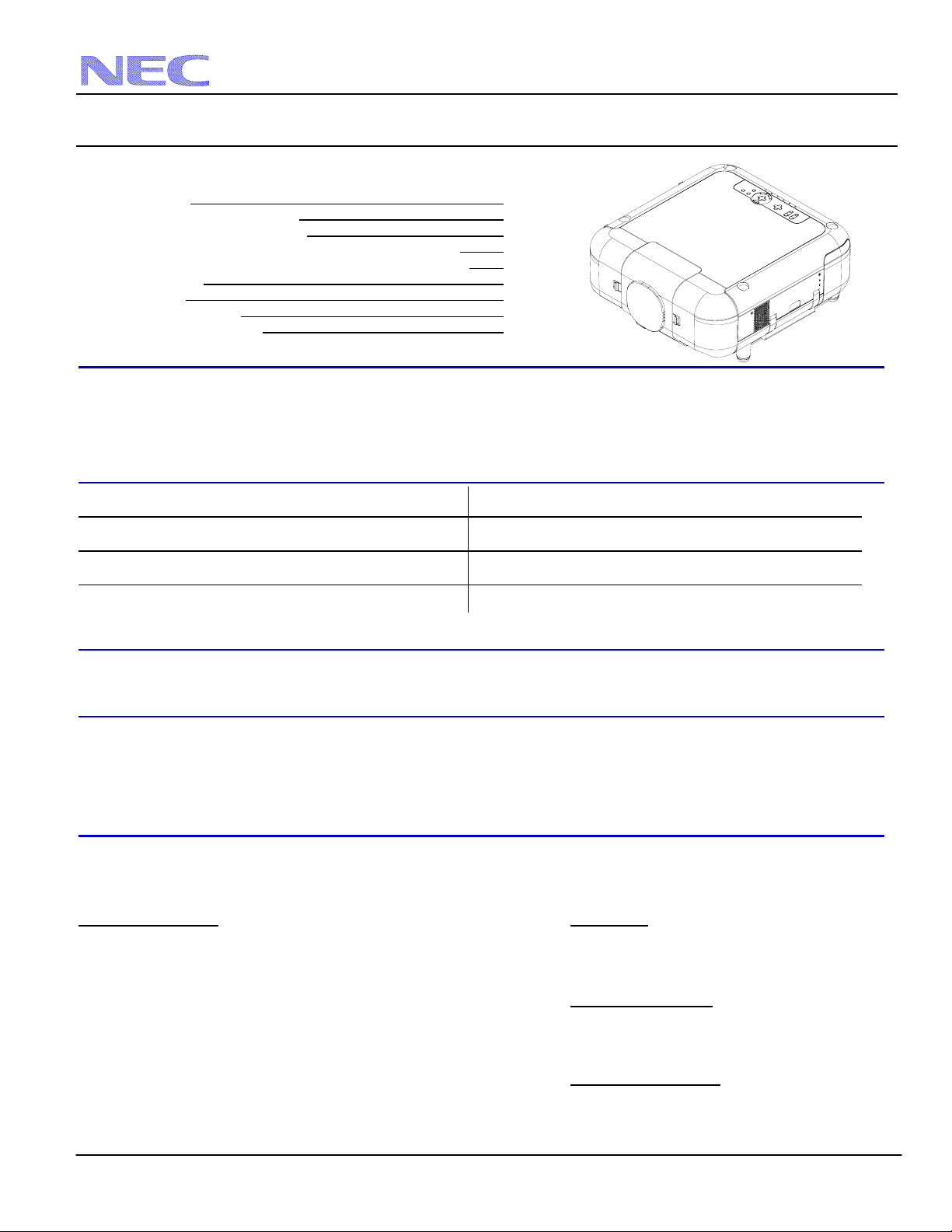
Product Description
Type: 3 panel LCD/Dual Lamp Projector Dimensions: 20.4”(W) x 9.5”(H) x 21.8”(D)
1.4” p-Si TFT w/MLA Weight: 40.6 lbs w/o lens
Resolution: GT5000: 1024x768 (4:3) / 1024x576 (16:9) Brightness: GT5000: up to 6000 ANSI (6 modes available)
GT6000: 1400x1050 (4:3) / 1400x788 (16:9) GT6000: up to 5300 ANSI (6 modes available)
Network Ready, integrated wired/optional wireless Power Lens Shift/Power Zoom/Power Focus
Lens Specifications
GT06RLB: Throw Ratio: ~0.6:1 Focal Length: 18.0mm GT20ZL: Throw Ratio: ~2.0-2.6:1 Focal Length: 57.4-74.7mm
Screen Sizes: 40”-120” F/#: 2.3 Screen Sizes: 40”-300” F/#: 1.8-2.5
GT10RLB: Throw Ratio: ~1.0:1 Focal Length: 28.9mm GT24ZLB: Throw Ratio: ~2.2-3.2:1 Focal Length: 64.0–93.0mm
Screen Sizes: 40”-250” F/#: 2.4 Screen Sizes: 60”-400” F/#: 2.5-3.2
GT12ZLB: Throw Ratio: ~1.2-1.7:1 Focal Length: 34.9-49.7mm GT34ZLB: Throw Ratio: ~3.2-4.8:1 Focal Length: 93.5-140.3mm
Screen Sizes: 40”-300” F/#: 2.3 - 3.4 Screen Sizes: 80”-500” F/#: 2.5-3.3
GT19ZLB: Throw Ratio: ~1.7-2.2:1 Focal Length: 48.9-63.7mm GT48ZLB: Throw Ratio: ~4.8-7.1:1 Focal Length: 143.0-209.0mm
Screen Sizes: 40”-300” F/#: 2.0-2.7 Screen Sizes: 80”-500” F/#: 2.2-3.2
Screen/Aspect Ratio
Both 4:3 and 16:9 screens are fully supported with proper aspect ratio control for both type sources using NEC developed
scaling technology. Menu selections have settings for each screen type and aspect ratio control for each source type.
Notes
• For screen sizes not indicated on the projection charts, use the formulas below.
• The ceiling must be strong enough to support the projector and the installation must be in accordance with any local
building codes.
• Distances are in inches, for millimeters multiply by 25.4.
• Distances may vary ±5%.
Formulas
The Projection Formulas use the image width for calculation. Image width is the same for all aspect ratios, only vertical image size
varies. For proper projector placement, determine the image width for a desired screen size. Use the Screen Formulas below to
calculate all screen dimensions. Plug in the image width for “W” in the Projection Formulas.
Refer to the diagrams and charts for popular screen sizes on page 2 and 3.
Projection Formulas: Definitions:
GT06RLB: C=0.6178W–2.287 W=Image Width
GT10RLB: C=1.0034W–2.087 H=Image Height (Size)
GT12ZLB: C(Wide)=1.2029W–2.823 --- C(Tele)=1.7223W–2.788 C=Throw Distance
GT19ZLB: C(Wide)=1.7010W–3.385 --- C(Tele)=2.2392W–3.272
GT20ZL: C(Wide)=2.0021W–3.987 --- C(Tele)=2.6237W–3.949 4:3 Screen Formulas:
GT24ZLB: C(Wide)=2.2181W–4.895 --- C(Tele)=3.2670W–4.836 W=Hx4/3
GT34ZLB: C(Wide)=3.2445W–7.016 --- C(Tele)=4.9132W–6.863 H=Wx3/4
GT48ZLB: C(Wide)=4.9390W–13.829 --- C(Tele)=7.2886W–13.586 Diagonal=Wx5/4
16:9 Screen Formulas:
W=Hx16/9
Note: Tilting the front of the projector up or down by more H=Wx9/16
than 45° from level could reduce lamp life by up to 20%. Diagonal=Wx18.358/16
Pg 1
Pg 2
Pg 3
Pg 4
Pg 5
Pg 6 & 7
Pg 8
Pg 9
Pg 10
www.necvisualsystems.com GT5000/6000 Page 1 of 10
Page 2

4:3 Screens
-
-
-
-
-
-
-
-
-
-
-
-
-
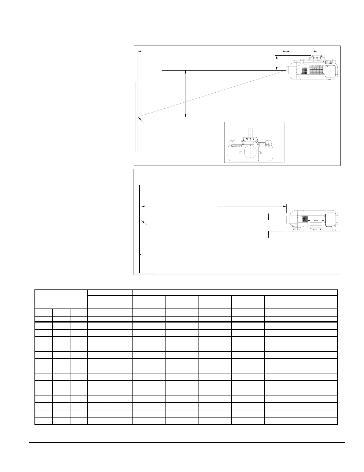
The following diagrams show the relationship bet ween projector position and the screen. Refer to the chart below for data.
Distances are in inches. For millimeters multiply by 25.4.
Ceiling Mounted Installation
C
Throw Distance
6.9"
Shift Range +
X=Distance from lens to mount ctr
Screen Ctr
Lens Centered
with Mount
Desktop Setup
Note: Lens shift is not available on
C
Throw Distance
GT06RLB & GT10RLB rear lenses, which
should only be used for “zero degree/nooffset” applications.
Screen Ctr
5.3"
Note: Tilting the front of the projector up
or down by more than 45° from level
could reduce lamp life by up to 20%.
Note: GT10RLB, GT19ZLB
are set back inside
shroud.
Distance chart for popular 4:3 screens
Screen Size (4:3)
DIAG W H 0.6:1 1.0:1
inches inches inches inches inches
40 32 24 17.5 30.0 35.7-52.3 51.0-68.4 60.1-80.0
60 48 36 27.4 46.1 54.9
72 57.6 43.2 33.3 55.7 66.5
84 67.2 50.4 39.2 65.3 78.0
90 72 54 42.2 70.2 83.8
100 80 60 47.1 78.2 93.4
120 96 72 57.0 94.2 112.7
150 120 90 NA 118.3 141.5
180 144 108 NA 142.4 170.4
200 160 120 NA 158.5 189.6
250 200 150 NA 198.6 237.8
300 240 180 NA NA 285.9
400 320 240 NA NA 704.9
500 400 300 NA NA 1290.8
Rear Lenses
GT06RLB GT10RLB
GT12ZLB GT19ZLB
1.2 - 1.7:1 1.7 - 2.2:1
inchesinches
79.9 78.3-104.2 92.1-122.0 101.6-152.0
96.4 94.6-125.7 111.3-147.2 122.9-183.3
113.0 110.9-147.2 130.6-172.4 144.2-214.7 211.0-323.3 318.1-476.2
121.2 119.1-158.0 140.2-185.0 154.8-230.4 226.6-346.9 341.8-511.2
135.0 132.7-175.9 156.2-205.9 172.6-256.5 252.5-386.2 381.3-569.5
162.6 159.9-211.7 188.2-247.9 208.0-308.8 304.5-464.8 460.3-686.1
203.9 200.7-265.4 236.3-310.9 261.3-387.2 382.3-582.7 578.9-861.0
245.2 241.6-319.2 284.3-373.9 314.5-465.6 460.2-700.6 697.4-1036.0
272.8 268.8-355.0 316.3-415.8 350.0-517.9 512.1-779.2 776.4-1152.6
341.7 336.8-444.6 396.4-520.8 438.7-648.6 641.9-975.8 974.0-1444.1
410.6 404.9-534.1 476.5-625.7 527.4-779.2 771.7-1172.3 1171.5-1735.7
NA NA
NANA NA
Note: For screen sizes not indicated on the chart, use the formulas on page 1.
Note: “NA” means it is outside the screen range for that lens. Refer to “Screen Si zes” in Lens Specifications on Page 1.
www.necvisualsystems.com GT5000/6000 Page 2 of 10
GT20ZL
2.0 - 2.6
inches
NA
Zoom Lenses
GT24ZLB
2.2 - 3.2:1
GT34ZLB
3.2 - 4.8 :1
inches
NA
inches
NA
NA
NA
1040.6 1031.2-1565.4 1566.7-2318.8
NA
X
GT12ZLB: X=16.1"
GT19ZLB: X=12.0"
GT20ZL: X=12.5"
GT24ZLB: X=12.4"
GT34ZLB: X=12.0"
GT48ZLB: X=14.0"
Note: GT10RLB, GT19ZLB
& GT34ZLB
are set back inside
shroud.
GT48ZLB
4.8 - 7.1: 1
inches
1958.4 1961.8-2901.9
NA
NA
NA
Page 3
16:9 Screens
-
-
-
-
-
-
-
-
-
-
-
-
-
The following diagrams show the relationship bet ween projector position and the screen. Refer to the chart below for data.
Distances are in inches. For millimeters multiply by 25.4.
Ceiling Mounted Installation
C
Throw Distance
6.9"
Vertical Position for a 16:9 screen:
The Vertical Position adjustment moves
16:9 image up and down in the unused
Shift Range +
X=Distance from lens to mount ctr
portion of the 4:3 panel. The range of
Vertical Position is dependent on aspect
ratio and 3D Reform used. If 3D Reform
is not used, the approximate range of
Vertical Position is +/-0.167H
(H=Screen Height) when using a 16:9
screen. This adjustment is only available
Screen Ctr
Lens Centered
with Mount
when the projector is set for ‘16:9’, ‘1.85:1’
or ‘2.35:1’ in the ‘Screen’ menu.
Desktop Setup
Note: Lens shift is not available on
C
Throw Distance
GT06RLB & GT10RLB rear lenses, which
should only be used for “zero degree/nooffset” applications.
Screen Ctr
5.3"
Note: Tilting the front of the projector up
or down by more than 45° from level
could reduce lamp life by up to 20%.
Note: GT10RLB, GT19ZLB
are set back inside
shroud.
Distance chart for popular 16:9 screens
Screen Size (16:9)
DIAG W H 0.6:1 1.0:1
inches inches inches inches inches
92 80 45 47.1 78.2 93.4-135.0 132.7-175.9 156.2-205.9 172.6-256.5 252.5-386.2 381.3-569.5
100 87 49 51.5 85.2 101.8
106 92 52 54.6 90.2 107.8
110 96 54 57.0 94.2 112.7
119 104 58.5 NA 102.3 122.3
123 107 60 NA 105.3 125.9
133 116 65 NA 114.3 136.7
135 118 66 NA 116.3 139.1
159 139 78 NA 137.4 164.4
161 140 79 NA 138.4 165.6
229 200 113 NA 198.6 237.8
275 240 135 NA NA 285.9
367 320 180 NA NA 704.9
459 400 225 NA NA 1290.8
Rear Lenses
GT06RLB GT10RLB
GT12ZLB GT19ZLB GT48ZLB
1.2 - 1.7:1 1.7 - 2.2:1
inchesinches inches
147.1 144.6-191.5 170.2-224.3 188.1-279.4 275.3-420.6 415.9-620.5
155.7 153.1-202.7 180.2-237.4 199.2-295.7 291.5-445.2 440.6-657.0
162.6 159.9-211.7 188.2-247.9 208.0-308.8 304.5-464.8 460.3-686.1
176.3 173.5-229.6 204.2-268.9 225.8-334.9 330.4-504.1 499.8-744.4
181.5 178.6-236.3 210.2-276.8 232.4-344.7 340.1-518.8 514.6-766.3
197.0 193.9-256.5 228.3-300.4 252.4-374.1 369.3-563.1 559.1-831.9
200.4 197.3-261.0 232.3-305.6 256.8-380.7 375.8-572.9 569.0-846.5
236.6 233.1-308.0 274.3-360.7 303.4-449.3 444.0-676.1 672.7-999.5
238.3 234.8-310.2 276.3-363.4 305.6-452.5 447.2-681.0 677.6-1006.8
341.7 336.8-444.6 396.4-520.8 438.7-648.6 641.9-975.8 974.0-1444.1
410.6 404.9-534.1 476.5-625.7 527.4-779.2 771.7-1172.3 1171.5-1735.7
NA NA
NANA NA
Note: For screen sizes not indicated on the chart, use the formulas on page 1.
Note: “NA” means it is outside the screen range for that lens. Refer to “Screen Si zes” in Lens Specifications on Page 1.
www.necvisualsystems.com GT5000/6000 Page 3 of 10
GT20ZL
2.0 - 2.6
NA
Zoom Lenses
GT24ZLB
2.2 - 3.2:1
GT34ZLB
3.2 - 4.8 :1
inches
inches
1040.6 1031.2-1565.4 1566.7-2318.8
NA
X
GT12ZLB: X=16.1"
GT19ZLB: X=12.0"
GT20ZL: X=12.5"
GT24ZLB: X=12.4"
GT34ZLB: X=12.0"
GT48ZLB: X=14.0"
Note: GT10RLB, GT19ZLB
& GT34ZLB
are set back inside
shroud.
4.8 - 7.1: 1
inches
1958.4 1961.8-2901.9
Page 4
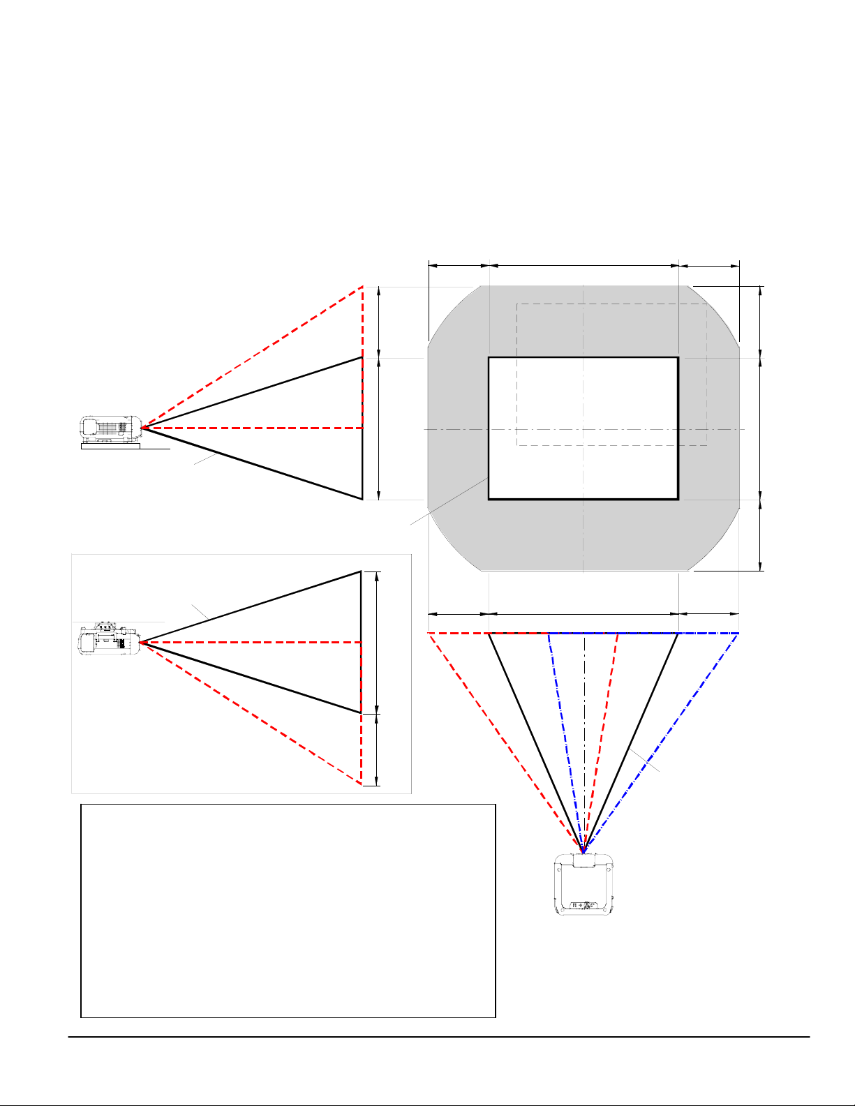
Lens Shift Adjustable Range
The top right diagram shows the location of the image position in the lens. The lens can be shifted within the shad ed area as shown
using the normal projection position as a starting point.
Maximum Possible Range for GT12ZLB/GT20ZL/GT48ZLB lenses:
*Values for 16:9 screens in parentheses.
Up: 0.5H (0.67H) H=Height of image (take care to use appropriate value for 4:3 or 16:9 screens)
Down: 0.5H (0.67H) W=Width of image
Right: 0.32W
Left: 0.32W
Note: Lens shift is not available on GT06RLB & GT10RLB rear lenses, which should only be used for “zero degree/no-offset” applications.
Note: If the lens is shifted in two directions combined, maximum range in either direction cannot be obtained due to rounded off area of
lens. (example: shift up and right) See top right diagram.
Note: The diagram below shows a 4:3 image as an example.
Desktop/Front
Vertical
0.5H
(0.67H)
H
Normal position
Normal projection position
Ceiling/Front
Vertical
Normal position
H
0.5H
(0.67H)
Warning:
• Installing the projector on the ceiling must be done by a qualified
technician.
• Tilting the front of the projector up or down by more than 45° from
level could reduce lamp life by up to 20%.
• Only use the projector on a solid, level surface. If the projector falls,
you could be injured and the projector severely damaged.
• Do not use the projector where temperatures vary greatly. The
projector must be used at temperatures between 32°F (0°C) and
95°F (35°C).
• Do not expose the projector to moisture, dust or smoke. This will
reduce the quality of the image.
• Ensure that you have adequate ventilation around the pro jector so
heat can dissipate. Do not cover any vents on the projector.
0.32W 0.32W
0.32W
Horizontal
W
W
0.32W
Normal position
0.5H
(0.67H)
H
0.5H
(0.67H)
www.necvisualsystems.com GT5000/6000 Page 4 of 10
Page 5

Lens Shift Adjustable Range (continued)
The top right diagram shows the location of the image position in the lens. The lens can be shifted within the shad ed area as shown
using the normal projection position as a starting point.
Maximum Possible Range for GT19ZLB/GT24ZLB/GT34ZLB lenses:
*Values for 16:9 screens in parentheses.
Up: 0.39H (0.52H) H=Height of image (take care to use appropriate value for 4:3 or 16:9 screens)
Down: 0.39H (0.52H) W=Width of image
Right: 0.24W
Left: 0.24W
Note: Lens shift is not available on GT06RLB & GT10RLB rear lenses, which should only be used for “zero degree/no-offset” applications.
Note: If the lens is shifted in two directions combined, maximum range in either direction cannot be obtained due to rounded off area of
lens. (example: shift up and right) See top right diagram.
Note: The diagram below shows a 4:3 image as an example.
Desktop/Front
Vertical
0.39H
(0.52H)
H
Normal position
Normal projection position
Ceiling/Front
Vertical
Normal position
H
0.39H
(0.52H)
Warning:
• Installing the projector on the ceiling must be done by a qualified
technician.
• Tilting the front of the projector up or down by more than 45° from
level could reduce lamp life by up to 20%.
• Only use the projector on a solid, level surface. If the projector falls,
you could be injured and the projector severely damaged.
• Do not use the projector where temperatures vary greatly. The
projector must be used at temperatures between 32°F (0°C) and
95°F (35°C).
• Do not expose the projector to moisture, dust or smoke. This will
reduce the quality of the image.
• Ensure that you have adequate ventilation around the pro jector so
heat can dissipate. Do not cover any vents on the projector.
0.24W 0.24W
0.24W
Horizontal
W
W
0.24W
Normal position
0.39H
(0.52H)
H
0.39H
(0.52H)
www.necvisualsystems.com GT5000/6000 Page 5 of 10
Page 6

Cabinet Dimensions
The following drawings show cabinet dimensions.
Dimensions are in inches. For millimeters multiply by 25.4.
Lamp (2)
Removes from side
Ventilation Out
Speaker (2)
Input Panel Covers
5.31
Cable Management
Inputs
AUDIO OUT
RGB2
RGB OUT
VIDEOS-VIDEO
AUDIOAUDIO
AUDIO
AUDIO
20.390.079
PC CONTROL
IN
SC TRIGGER
USB(B)
AC SW
PC CARD
REMOTE1
REMOTE2
IN OUT
2
1
LAN
AC IN
DVI
SLOT2
SLOT1
RGB1
USB(A)
OUT
Control
0.315 21.57
8.860.669
9.53
Lens Cap
www.necvisualsystems.com GT5000/6000 Page 6 of 10
Page 7

Cabinet Dimensions (continued)
The following drawings show cabinet dimensions.
Dimensions are in inches. For millimeters multiply by 25.4.
Lamp (1)
Removes from side
Air Filter (1)
Removes from side
Ventilation In
9.65
1.18
6.61
Speaker (1)
M4*20 MAX
For Mount
www.necvisualsystems.com GT5000/6000 Page 7 of 10
Lamp (2)
Removes from side
9.45
M4*8 MAX
For Mount
M4*20 MAX
For Mount
4.92 4.92
Air Filter (2)
Removes from side
Page 8

Lens Dimensions
The following drawings show the added lens dimensions for the lenses that protrude from the cabinet.
Dimensions are in inches. For millimeters multiply by 25.4.
Lenses that stick out from the shroud Lenses that are set back inside the shroud
www.necvisualsystems.com GT5000/6000 Page 8 of 10
3.9
3.8
0.15
3.7 4.9
0.08
2.8
1.7
3.4 4.5
6.5
5.2 6.3
Lens
Shift Range
Lens
Shift Range
4.0
GT06RLB
Lens
Shift Range
GT12ZLB
GT20ZL
GT24ZLB
Lens
Shift Range
GT48ZLB
3.7
0.30
3.7 4.9
0.29
2.9 4.0
1.5
GT10RLB
Lens
Shift Range
GT19ZLB
Lens
Shift Range
GT34ZLB
Page 9

Optional Ceiling Mount Dimensions (Model #: GT60CM)
The following drawings show ceiling mount dimensions.
Dimensions are in inches. For millimeters multiply by 25.4.
5.72
FRONT
4.60 2.25
11.50
Note: Ceiling mount kit comes with base mount, projector adapter plate and screws. Other hardware (treaded pipe, threaded rod,
etc..) must be supplied by the installer. For hardware contact Display Devices at 303-412-0399.
www.necvisualsystems.com GT5000/6000 Page 9 of 10
1.5 NPT
0.625 DIA x 4
3.25
2.19
10.50
WEIGHT: 8 LBS
Page 10

Input Panel
AUDIO OUT
AUDIO
AUDIO
SLOT1
RGB2
AUDIO
DVI
SLOT2
USB(A)
PC CONTROL
IN
USB(B)
RGB OUT
VIDEOS-VIDEO
OUT
SC TRIGGER
AUDIOAUDIO
RGB1
AC SW
Control Codes
Function Code Data
POWER ON 02H 00H 00H 00H 00H 02H
POWER OFF 02H 01H 00H 00H 00H 03H
INPUT SELECT RGB 1 02H 03H 00H 00H 02H 01H 01H 09H
INPUT SELECT RGB 2 02H 03H 00H 00H 02H 01H 02H 0AH
INPUT SELECT VIDEO 02H 03H 00H 00H 02H 01H 06H 0EH
INPUT SELECT S-VIDEO 02H 03H 00H 00H 02H 01H 0BH 13H
INPUT SELECT DVI (DIGITAL) 02H 03H 00H 00H 02H 01H 1AH 22H
INPUT SELECT VIEWER 02H 03H 00H 00H 02H 01H 1FH 27H
LAN 02H 03H 00H 00H 02H 01H 20H 28H
SLOT 1-1 02H 03H 00H 00H 02H 01H 24H 2CH
SLOT 1-2 02H 03H 00H 00H 02H 01H 25H 2DH
SLOT 2-1 02H 03H 00H 00H 02H 01H 29H 31H
SLOT 2-2 02H 03H 00H 00H 02H 01H 2AH 32H
RGB1(VIDEO) 02H 03H 00H 00H 02H 01H 07H 0FH
RGB1(S-VIDEO) 02H 03H 00H 00H 02H 01H 0CH 14H
PICTURE MUTE ON 02H 10H 00H 00H 00H 12H
PICTURE MUTE OFF 02H 11H 00H 00H 00H 13H
SOUND MUTE ON 02H 12H 00H 00H 00H 14H
SOUND MUTE OFF 02H 13H 00H 00H 00H 15H
ON SCREEN MUTE ON 02H 14H 00H 00H 00H 16H
ON SCREEN MUTE OFF 02H 15H 00H 00H 00H 17H
ASPECT RATIO 1.25:1 (5:4) 03H 10H 00H 00H 05H 18H 00H 00H 00H 00H 30H
1.33:1 (4:3) 03H 10H 00H 00H 05H 18H 00H 00H 01H 00H 31H
1.78:1 (16:9) 03H 10H 00H 00H 05H 18H 00H 00H 02H 00H 32H
1.85:1 03H 10H 00H 00H 05H 18H 00H 00H 03H 00H 33H
2.35:1 03H 10H 00H 00H 05H 18H 00H 00H 04H 00H 34H
AUTO ADJUST 02H 0FH 00H 00H 02H 05H 00H 18H
Note: Contact your NEC rep for codes not listed.
Cable Connection
Communication Protocol: PC Control Connector (D-Sub 9P)
Baud Rate: 38400 bps
Data Length: 8 bits
Parity: No Parity
Stop Bit: One bit
X on/off: None
Communications: Full duplex
NOTE1: It is recommended to set the projector to “Idle Mode” in the
Setup menu for best Power ON response.
NOTE2: Pins 1, 4, 6, and 9 are used inside the projector.
NOTE3: Jumper “Request to send” and “Clear to Send” together on
both ends of the cable to simplify cable connection.
NOTE4: For long cable runs it is recommended to set communication
speed to 9600 bps in the Setup menu.
www.necvisualsystems.com GT5000/6000 Page 10 of 10
12
678
PC CARD
LAN
REMOTE1
REMOTE2
IN
AC IN
34
9
2
1
OUT
To TxD of PC
To RxD of PC
To GND of PC
5
To RTS of PC
To CTS of PC
 Loading...