

Page 1
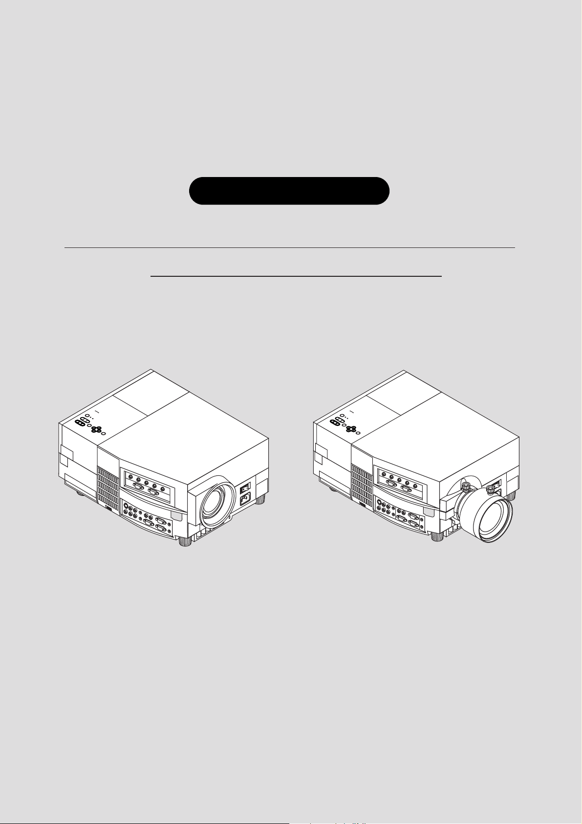
Graphic Theatre
MultiSync™ GT2000™/GT2000R
™
LCD Projector User’s Manual
ON / OFF
POWER
STATUS
ZOOM
FOCUS
ENTER
-
SELECT
MENU
+
AC IN
ON / OFF
POWER
STATUS
ZOOM
FOCUS
ENTER
-
SELECT
MENU
+
AC IN
Page 2
IMPORTANT INFORMATION
Precautions
Please read this manual carefully before using your NEC
MultiSync GT2000/GT2000R LCD Projector and keep the
manual handy for future reference.
Your serial number is located under the name plate label on the right
side of your MultiSync GT2000/GT2000R . Record it here:
WARNING
TO PREVENT FIRE OR SHOCK, DO NOT EXPOSE THIS
UNIT TO RAIN OR MOISTURE. DO NOT USE THIS
UNIT’S GROUNDED PLUG WITH AN EXTENSION
CORD OR IN AN OUTLET UNLESS ALL THREE
PRONGS CAN BE FULLY INSERTED. DO NOT OPEN
THE CABINET. THERE ARE HIGH-VOLTA GE COMPONENTS INSIDE. ALL SERVICING MUST BE DONE BY
QUALIFIED NEC SERVICE PERSONNEL.
CAUTION
To turn off main power, be sure to remove the plug
from power outlet. The power outlet socket should be
installed as near to the equipment as possible, and should
be easily accessible.
CAUTION
TO PREVENT SHOCK, DO NOT OPEN THE
CABINET. NO USER-SERVICEABLE PARTS
INSIDE. REFER SERVICING TO QUALIFIED
NEC SERVICE PERSONNEL.
This symbol warns the user that uninsulated
voltage within the unit may be sufficient to
cause electrical shock. Therefore, it is dangerous to make any kind of contact with any
part inside of the unit.
This symbol alerts the user that important
information concerning the operation and
maintenance of this unit has been provided.
The information should be read carefully to
avoid problems.
DOC Compliance Notice
This Class A digital apparatus meets all requirements of the
Canadian Interference-Causing Equipment Regulations.
3. GSGV Acoustic Noise Information Ordinance:
The sound pressure level is less than 70 dB(A) according to ISO 3744 or
ISO 7779.
Important Safeguards
These safety instructions are to ensure the long life of your LCD
projector and to prevent fire and shock. Please read them carefully and
heed all warnings.
Installation
1. For best results, use your LCD projector in a darkened room.
2. Place the projector on a flat level surf ace in a dry area away from dust
and moisture.
3. Do not place your LCD projector in direct sunlight, near heaters or
heat radiating appliances.
4. Exposure to direct sunlight, smoke or steam can harm internal
components.
5. Handle your LCD projector carefully. Dropping or jarring can damage internal components.
6. Do not place heavy objects on top of the LCD projector.
7. If installing the LCD projector on the ceiling:
a. The ceiling must be strong enough to support the LCD projector
and the installation must be in accordance with any local building codes.
b. The LCD projector must be installed by qualified NEC service
personnel.
Power Supply
1. The LCD projector is designed to operate on a power supply of 100120 or 220-240 V 50/60 Hz AC. Ensure that your power supply fits
this requirement before attempting to use your LCD projector.
2. Handle the power cable carefully and avoid excessive bending. A
damaged cord can cause electric shock or fire.
3. If the LCD projector is not to be used for an extended period of time,
disconnect the plug from the power outlet.
Three types of power cable are supplied with this LCD projector: three-
pin type for Japan, U. S. A. and Canada. Two-pin type for Germany.
For Japan
(black)
For Germany
RF Interference
WARNING
The Federal Communications Commission does not allow any
modifications or changes to the unit EXCEPT those specified by
NEC Technologies in this manual. Failure to comply with this
government regulation could void your right to operate this equipment.
This equipment has been tested and found to comply with the limits
for a Class A digital device , pursuant to P ar t 15 of the FCC Rules.
These limits are designed to provide reasonable protection against
harmful interference in a commercial installation. This equipment
generates, uses and can radiate radio frequency energy and, if not
installed and used in accordance with the instructions, may cause
harmful interference to radio communications. Operation of this
equipment in a residential area is likely to cause harmful interference in which case the user will be required to correct the interference at their own expense.
For North
America
(gray)
E-2
Page 3

Cleaning
1. Unplug the LCD projector before cleaning.
2. Clean the cabinet periodically with a damp cloth. If heavily soiled,
use a mild detergent. Never use strong deter gents or solvents such as
alcohol or thinner.
3. Use a blower or lens paper to clean the lens, and be careful not to
scratch or mar the lens.
4. Clean the air filter with a vacuum cleaner after every 100 hours of
operation.
a. Clean the outside of the filter with a vacuum cleaner.
b. Do not use water or any other liquid to clean the air f ilter.
c. Do not operate your LCD projector without the air filter.
Lamp Replacement
• Perform lamp replacement in accordance with the instructions on
page E-73.
• Be sure to replace the lamp when the Status light comes on. If you
continue to use the lamp after 2000 hours of use, the lamp bulb may
shatter, and pieces of glass may be scattered in the lamp case. Do not
touch them as the pieces of glass may cause injury. If this happens,
contact your NEC dealer for lamp replacement.
• Allow a minimum of ONE minute to elapse between turning the lamp
off and on. High voltage is applied to the lamp immediately when the
power is turned on. Therefore turning the pow er off and quickly back
on may shorten the life of your lamp and result in damage to your
LCD projector.
Fire and Shock Precautions
1. Ensure that there is sufficient ventilation and that vents are unobstructed to prevent the build-up of heat inside your LCD projector.
Allow at least 3 inches (10cm) of space between your LCD projector
and a wall.
2. Prevent foreign objects such as paper clips and bits of paper from
falling into your LCD projector. Do not attempt to retr ieve any objects
that might fall into your projector. Do not insert any metal objects
such as a wire or screwdriver into your LCD project. If something
should fall into your projector, disconnect it immediately and hav e the
object removed by a qualified NEC service person.
3. Do not place any liquids or plants (which require liquids) on top of
your LCD projector.
• Do not look into the lens while the projector is on.
Serious damage to your eyes could result.
E-3
Page 4
ATTENTION
RISQUE D’ELECTROCUTION NE PAS OUVRIR
DOC avis de conformation
DOC avis de conformation
Cet appareil numérique de la classe A respecte toutes les exigences
du Règlement sur le Matériel Brouilleur du Canada.
ATTENTION
Pour couper l'alimentation principale, s'assurer de
retirer la fiche de la prise de courant.
La prise de courant murale doit être installée le
plus près possible de l'équipement, et doit être
facilement accessible.
Ce symbole a pour but de prévenir
l’utilisateur de la présence d’une tension
dangereuse, non isolée se trouvant à
l’intérieur de l’appareil. Elle est d’une
intensité suffisante pour constituer un risque
d’électrocution. Eviter le contact avec les
pièces à l’intérieur de cet appareil.
Ce symbole a pour but de prévenir
l’utilisateur de la présence d’importantes instructions concernant l’entretien et le
fonctionnement de cet appareil. Par
conséquent, elles doivent être lues
attentivement afin d’éviter des problèmes.
AVERTISSEMENT
AFIN DE REDUIRE LES RISQUES D’INCENDIE OU
D’ELECTROCUTION, NE PAS EXPOSER CET
APPAREIL A LA PLUIE OU A L’HUMIDITE. AUSSI, NE
PAS UTILISER LA FICHE POLARISEE AVEC UN
PROLONGATEUR OU UNE AUTRE PRISE DE COURANT SAUF SI CES LAMES PEUVENT ETRE INSEREES
A FOND. NE PAS OUVRIR LE COFFRET, DES
COMPOSANTES HAUTE TENSION SE TROUVENT A
L’INTERIEUR. LAISSER A UN PERSONNEL QUALIFIE
LE SOIN DE REPARER CET APPAREIL.
Importantes précautions de sécurité
Les points suivants sont des précautions de sécurité importantes
destinées à garantir une longue durée de service du projecteur à
écran à cristaux liquides (LCD) et afin d’éviter un incendie et des
risques d’électrocution. S’assurer de lire attentivement ces
précautions de sécurité et respecter tous les avertissements décrits
ci-dessous.
Installation
1. Pour un fonctionnement optimal, utiliser le projecteur à écran à
cristaux liquides (LCD) dans une pièce sombre.
2. Placer le projecteur à écran à cristaux liquides (LCD) sur une
surface à niveau et dans un endroit sec exempt de poussières et
d’humidité.
3. Ne pas placer le projecteur à écran à cristaux liquides (LCD) en
plein soleil, près d’appareils ménagers ou d’autres appareils de
chauffage.
4. La fumée, la vapeur et l’exposition aux rayons directs du soleil
risquent de détériorer sérieusement les composantes internes.
5.Eviter des manipulations brusques lors du déplacement du
projecteur à écran à cristaux liquides (LCD), car un choc violent
pourrait endommager les composantes internes.
6. Ne pas deposer d’objets lourds sur le dessus du projecteur à écran
à cristaux liquides (LCD).
7. Lors de l’installation du projecteur à écran à cristaux liquides
(LCD) au plafond, respecter les instructions suivantes.
a. Le plafond doit être suffisamment solide pour supporter le
poids du projecteur à écran à cristaux liquides (LCD) et il
doit être installé selon les codes de construction locaux.
b. Le projecteur à écran à cristaux liquides (LCD) doit être
installé par un personnel qualifié.
Alimentation
1. Le projecteur à écran à cristaux liquides (LCD) est conçu pour
fonctionner à 100-120 ou 220-240VCA 50/60Hz. S’assurer que la
tension d’alimentation locale satisfait cette exigence avant
d’utiliser le projecteur.
2. Manipuler le câble d’alimentation avec précaution et éviter de le
plier excessivement. Un cordon endommagé risque de pr ov oquer
une électrocution ou un incendie.
3. Si le projecteur à écran à cristaux liquides (LCD) n’est pas utilisé
pendant une période prolongée, retirer la fiche de la prise secteur .
E-4
Page 5

Nettoyage
1.Débrancher le projecteur à écran à cristaux liquides (LCD) de la
prise d’alimentation avant le nettoyage.
2.Nettoyer régulièrement le coffret avec un chiffon doux. S’il y a
des taches tenaces, utiliser une solution d’un détergent doux. Ne
jamais utiliser de détergents puissants ou des solvants, tel que
l’alcool ou un diluant pour nettoyer le projecteur à écran à cristaux
liquides (LCD).
3.Utiliser un appareil diffuseur chauffant ou du papier de nettoyage
de lentille disponible dans le commerce pour nettoyer la lentille.
Ne pas frapper ou rayer la surface de la lentille, car des défauts
risquent de se produire sur la surface de la lentille.
4.Nettoyer le filtre à air toutes les 100 heures.
a. Nettoyer seulement l’extérieur avec un aspirateur.
b. Ne pas nettoyer le filtre à air avec de l’eau ou un liquide.
c. Ne pas utiliser le projecteur à écran à cristaux liquides (LCD)
sans le filtre à air.
Remplacement de la lampe
• Effectuer le remplacement de la lampe suiv ant les instructions de
la page 75.
• Assurez-vous de bien remplacer la lampe lorsque le voyant
d’usure s’allume. Si vous continuez d’utiliser la lampe après 2000
heures d’utilisation, l’ampoule peut se briser et des brisures de
verre peuvent être éparpillées dans le compartiment de la lampe.
Ne les touchez pas car elles peuvent vous blesser. Dans ce cas,
contactez votre revendeur NEC af in de procéder au remplacement
de la lampe.
• Attendez minimum UNE minute après avoir éteint la lampe av ant de
la rallumer. Une haute tension est immédiatement appliquée à la
lampe quand celle-ci est mise sous tension. Par conséquent, éteindre,
puis tout de suite rallumer peut abréger la vie de votre lampe et
endommager votre projecteur LCD.
Précautions pour éviter un incendie
ou une électrocution
1. Une ventilation appropriée doit être assurée afin d’éviter une accumulation de chaleur à l’intérieur du projecteur à écran à cristaux
liquides (LCD). S’assurer que les trous de ventilation ne sont pas
obstrués. Laisser un espace d’au moins 10 cm (quatre pouces) entre
le projecteur à écran à cristaux liquides (LCD) et les murs.
2. Eviter que des objets étrangers, des agrafes, des clous et du papier, par
exemple, pénètrent à l’intérieur du projecteur à écran à cristaux
liquides (LCD). Ne pas essayer de récupérer ces objets soi-même ou
ne pas insérer des objets métalliques, des fils et des tourne-vis, par
exemple à l’intérieur du projecteur à écran à cristaux liquides (LCD).
Si un objet tombe à l’intérieur du projecteur à écran à cristaux liquides
(LCD), le débrancher immédiatement et contacter un dépanneur
qualifié pour retirer l’objet.
3. Ne pas placer des liquides sur le dessus du projecteur à écran à
cristaux liquides (LCD).
• Ne regardez pas à l’intérieur de l’objectif lorsque le
projecteur est en marche. Vous risquez de vous blesser
gravement aux yeux.
E-5
Page 6

LIMITED WARRANTY (USA AND CANADA ONLY)
NEC MultiSync® LCD Projector Products
NEC T echnologies, Inc. (hereafter NECTECH) warrants this
product to be free from defects in material and workmanship
under the following terms.
This warranty extends only to you, the original purchaser , and
is not transferable. This warranty extends only to products and
distributed by us in the U.S.A or Canada.
HOW LONG IS THE WARRANTY?
Parts and labor are warranted for (2) two years from the date
of the first customer purchase. The lamp is warranted f or 2000
hours of operating time or six months, whichever comes fir st.
WHO IS PROTECTED?
This warranty may be enforced only by the first purchaser.
WHAT IS COVERED AND WHAT IS NOT
COVERED
Except as specified below, this warranty cov ers all def ects in
material or workmanship in this product. The following are
not covered by the warranty:
1.Any product which is not distributed in the U.S.A. or
Canada by NECTECH or which is not purchased in the
U.S.A. or Canada from an authorized NECTECH dealer.
For a listing of authorized dealers please contact
NECTECH at 800-836-0655.
2.Any product on which the serial number has been defaced,
modified or removed. NECTECH’S LIABILITY FOR
ANY DEFECTIVE PRODUCT IS LIMITED TO THE
REPAIR OR REPLACEMENT OF THE PRODUCT AT
OUR OPTION. REPLACEMENT PRODUCTS MAY BE
NEW OR ‘LIKE NEW’.
3.NECTECH SHALL NOT BE LIABLE FOR : Damage,
deterioration or malfunction resulting from:
a. Accident, misuse, abuse, neglect, fire, water, lightning
or other acts of nature, unauthorized product modification, or failure to follow instructions supplied with the
product.
b.Repair or attempted repair by anyone not authorized by
NECTECH.
1.Removal or installation charges.
2. Costs of initial technical adjustments (set-up), including
adjustment of user controls. These costs are the responsibility of the NECTECH dealer from whom the product was
purchased.
3.Payment of shipping charges.
HOW YOU CAN GET WARRANTY SERVICE
1.To obtain service on your product, consult the dealer from
whom you purchased the product.
2. Whenever warranty service is required, the original dated
inv oice (or a copy) must be presented as proof of warranty
coverage. Please be prepared to describe or demonstrate the
problem to your dealer.
3.For the name of the nearest NECTECH authorized service
center, call NECTECH at 800-836-0655.
LIMITATION OF IMPLIED WARRANTIES
ALL IMPLIED WARRANTIES, INCLUDING WARRANTIES OF MERCHANTABILITY AND FITNESS FOR A
PARTICULAR PURPOSE, ARE LIMITED IN DURATION
TO THE LENGTH OF THIS WARRANTY.
EXCLUSION OF DAMAGES
NECTECH’S LIABILITY FOR ANY DEFECTIVE PRODUCT IS LIMITED TO THE REPAIR OR REPLACEMENT
OF THE PRODUCT AT OUR OPTION. NECTECH SHALL
NOT BE LIABLE FOR:
1. DAMAGE TO OTHER PROPERTY CAUSED BY ANY
DEFECTS IN THIS PRODUCT, DAMAGES BASED
UPON INCONVENIENCE, LOSS OF USE OF THE
PRODUCT, LOSS OF TIME, COMMERCIAL LOSS; OR
2.ANY OTHER DAMAGES, WHETHER INCIDENTAL,
CONSEQUENTIAL OR OTHERWISE. SOME STATES
DO NOT ALLOW LIMITATIONS ON HOW LONG AN
IMPLIED WARRANTY LASTS AND/OR DO NOT ALLOW THE EXCLUSION OR LIMITATION OF INCIDENTAL OR CONSEQUENTIAL DAMAGES, SO THE
ABOVE LIMITATIONS AND EXCLUSIONS MAY NO T
APPLY TO Y O U.
c. Any shipment of the product (claims must be presented
to the carrier).
d.Removal or installation of the product.
e. Any other cause which does not relate to a product
defect.
4. Cartons, carrying cases, batteries, external cabinets, magnetic tapes, or any accessories used in connection with the
product.
WHAT NEC WILL COVER
We will pay labor and material expenses for covered items.
But we will not pay for the following:
HOW STATE LAW RELATES TO THE WARRANTY
This warranty gives you specific legal rights, and you may
also have other rights which vary from state to state.
FOR MORE INFORMA TION, TELEPHONE 800-836-0655
NEC TECHNOLOGIES, INC.
1250 N. Arlington Heights Road, Suite 500
Itasca, Illinois 60143-1248
NOTE: All products returned to NECTECH for service
MUST have prior approval. To get approval, call NEC
Technologies at
800-836-0655.
E-6
Page 7

TABLE OF CONTENTS
1. Introduction
What’ s I n The Box? ...................................................................................................... E-8
Getting T o Know Your MultiSync GT2000/GT2000R LCD Projector .......................... E-9
Projector Cabinet ................................................................................................... E-9
T op Fe atures ........................................................................................................ E-10
Terminal Panel Features....................................................................................... E-11
Remote Control Features ..................................................................................... E-13
2. Installation
Setting Up Your MultiSync GT2000/GT2000R LCD Projector .................................. E-17
Using A Tabletop Or Cart .................................................................................... E-18
Adjusting The Focus On GT2000R...................................................................... E-18
Ceiling Installation............................................................................................... E-21
Reflecting The Image/ Rear Screen Projection (GT2000R Only)......................... E-23
3. Connections
Wiring Diagram .......................................................................................................... E-25
PC Control .................................................................................................................. E-26
Connections With ISS-6020 ........................................................................................ E-28
Connecting One ISS-6020 ................................................................................... E-28
Connecting Multiple ISS-6020s ........................................................................... E-29
Connecting Multiple Projectors .................................................................................. E-30
Operating Multiple Projectors With Remote Control .................................................. E-31
External Control.......................................................................................................... E-32
4. Operation
General Controls ......................................................................................................... E-34
Set-Up......................................................................................................................... E-36
Adjusting The Picture And The Audio ........................................................................ E-44
Adjusting The Screen .................................................................................................. E-49
Using User Memory And Channel Memory................................................................ E-56
Controlling Switcher ................................................................................................... E-70
4. Maintenance
Replacing The Lamp ................................................................................................... E-73
Cleaning And Replacing The Filter............................................................................. E-74
Remote Control Battery Installation............................................................................ E-74
5. Troubleshooting
Status Light Messages................................................................................................. E-77
Common Problems & Solutions.................................................................................. E-78
6. Specifications
Optical ........................................................................................................................ E-79
Electrical ..................................................................................................................... E-79
Mechanical ................................................................................................................. E-79
D-Sub Pin Assignments .............................................................................................. E-81
Displayable V ideo Signals........................................................................................... E-82
PC Control Command Reference ................................................................................ E-83
E-7
Page 8
1
INTRODUCTION
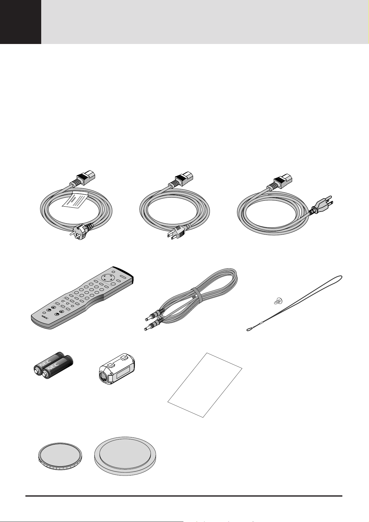
What’s In The Box?
Make sure your box contains everything listed. If any pieces are
missing, contact your dealer. Please save the original box and
packing materials if you ever need to ship your MultiSync GT2000/
GT2000R LCD Projector.
• NEC MultiSync GT2000/GT2000R LCD Projector
• Remote Control And Cables
• Power Cable
• T wo AAA Batteries
• User’s Manual
• String and Rivet (GT2000 only)
• Ferrite Clamp
Power cable (3 types)
For Germany
Remote control
For Japan
Remote cable
For USA or Canada
String and rivet (GT2000 only)
Batteries (AAA22)
Lens cap (attatched to the projector at the factory)
For GT2000
Ferrite clamp for remote cable
For GT2000R
User’ s manual (English / German and
Japanese)
User's
Manual
E-8
Page 9
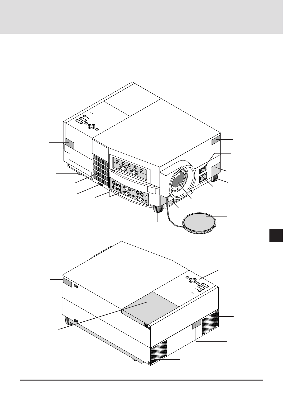
Getting To Know Your MultiSync
GT2000/GT2000R LCD Projector
ON / OFF
POWER
STATUS
ZOOM
-
FOCUS
ENTER
-
+
+
-
SELECT
+
MENU
Remote Sensor
Rear Foot
Filter Cover
Latch
Ter minal Panel
Tilt Foot
Front Vent
Lens
Remote Sensor
Main Power Switch
AC IN
One-Touch
Tilt button
Tilt Foot
AC Input
Plug the female end of the supplied
power cable here, and the male end
into a properly grounded outlet.
Lens Cap
Top Features
Remote Sensor
Lamp Housing Cover
E-9
MENU
SELECT
ENTER
STATUS
POWER
ON / OFF
Built-In Speaker
(2W)
FOCUS
ZOOM
Built-In Speaker
(2W)
Remote Sensor
Page 10
MENU
SELECT
ENTER
STATUS
ZOOM FOCUS
POWER
ON / OFF
-
+
-
+-+
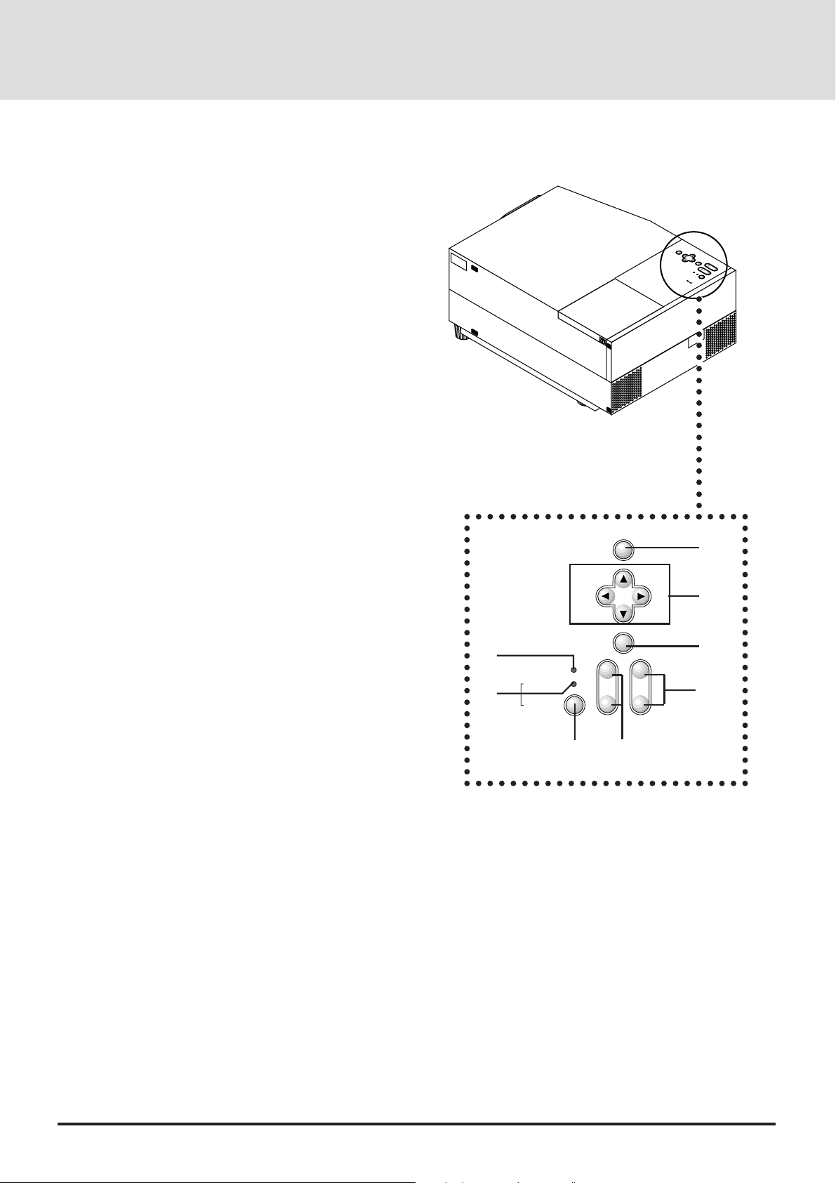
Top Features
1 Power Button
Use this button to turn the power on and off when the Main
Power Switch is on and the LCD projector is in standby.
To turn off the projector, press and hold this button for at
least 2 seconds.
2 Menu Button
Displays the on- screen menu. A press of this button while
the on-screen menu is displayed will move back to the
previous menu step.
3 Select (▲▼
Select: After you press the “Menu” button, use the ▲ or
§ ©
(▲▼
(+)(–): Use these buttons while you' re in the adjustment
4 Enter Button
Executes your menu selection.
5 (+) (–) Zoom Buttons
§ ©
) / (+)(–) Buttons
)
▼ button to select the menu item you wish to
adjust.
mode to change the level of a selected menu item.
These buttons are also used to set an item in the
other menus.
MENU
SELECT
ENTER
FOCUS
ZOOM
STATUS
POWER
ON / OFF
○○○○○○○○○○○○○○○○○○○○
2
Press the (+) button to make the image larger; press (–) to
make the image smaller. (This feature is not available on
GT2000R.)
6 (+) (–) Focus Buttons
Press the (+) or (–) buttons to focus an image. (This feature is
not available on GT2000R.)
7 Power Indicator
When this indicator is green, the LCD projector is on; when
the indicator is amber, it is in standby mode.
8 Status Indicator
When this is lit red continually, it's warning you that the
projection lamp has exceed 2000 hours of service. After this
light appears, it is advisable to replace the projection lamp as
soon as possible.(See page E-73)
In addition the message "LAMP USAGE XX HOURS"
appears continually when the on-screen menu is not displayed.
If this light blinks red rapidly , it indicates that either the lamp
cover or filter cover is not attached properly. See the Status
Light Messages on page E-77 for more details.
When the GT2000/GT2000R is used with the ISS-6020
switcher in bundled operation, this indicator lights green.
The green light blinks when the ISS-6020 Switcher is not
connected with the projector correctly .
3
8
7
1
5
4
6
E-10
Page 11
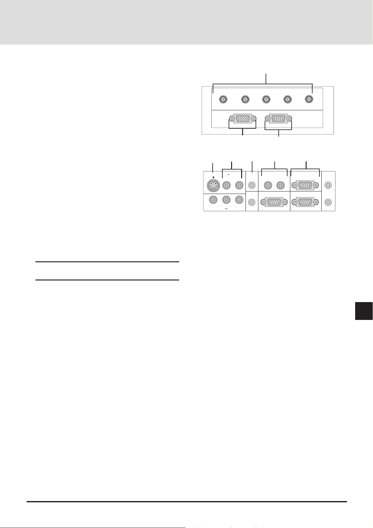
Terminal Panel Features
This panel is located on the left side and is where you connect your
cables.
1
1 R/Cr, G/Y, B/Cb, H/ HV and V [RGB 1] Inputs (BNC)
Connect R,G,B,H (Horizontal sync) and V (Vertical sync)
outputs of external equipment such as the NEC ISS-6020
Switcher or IPS-4000.
If using a component with a combined sync (SYNC) output,
connect it to the H/V terminal. When using luminance and
color-difference signals of HDTV and DVD, connect Pr/Cr
to the R, Y to the G and Pb/Cb to the B input of the projector .
2
RGB (Y, Cb,Cr) Input 2 Connector (Mini D-Sub 15 pin)
Connect your PC, DVD player with Y/Cb/Cr outputs or
other RGB equipment such as IBM or compatible computers. The optional Component V. Cable is required for Y/Cb/
Cr input connection.
3 RGB Output Connector (Mini D-Sub 15 pin)
You can use this connector to loop your computer image to
an external monitor from either the RGB 1 or RGB 2 input
source.
4 S-Video Input
Here is where you connect the S-V ideo input from an e xter nal source such as a VCR or laser disc player.
NOTE: S-Video provides more vivid color and higher
resolution than the traditional composite video format.
R/Cr G/YB
RGB
INPUT 2
2
4
S-VIDEO INPUT AUDIO
VIDEO INPUT AUDIO
5
L/MONO R L/MONO R
L/MONO R
6
RGB 2
AUDIO
AUDIO
OUTPUT
/
Cb
RGB 1 AUDIO
/
H
3
7
REMOTE 1
HV V
RGB
OUTPUT
REMOTE 2/PC
EXT
8
-
CTL
REMOTE
INPUT
REMOTE
OUTPUT
5 Left Channel/Mono Audio Input Jack (RCA)
This is your left channel audio input for stereo sound coming
from S-Video equipment or audio system. This also serves as
your monaural audio input.
Right Channel Audio Input Jack
This is your right channel audio input for stereo sound.
6 RGB 2 Audio Input Mini Jack
You can use this connector to output sound from the RGB 2
Input source.
7
RGB 1 Left Channel/Mono Audio Input Jack (RCA)
This is your left channel audio input for stereo sound coming
from the RGB Input 1 source.
This also serves as your monaural audio input.
RGB 1 Right Channel Audio Input Jack
This is your right channel audio input for stereo sound from
the RGB Input 1 source.
8 Remote 2/PC Connector (Mini D-Sub 15 pin)
Use this connector to attach an RS-232C cable when a
computer or similar device will control the projector or when
the projector is used with multiple projectors.
E-11
Page 12
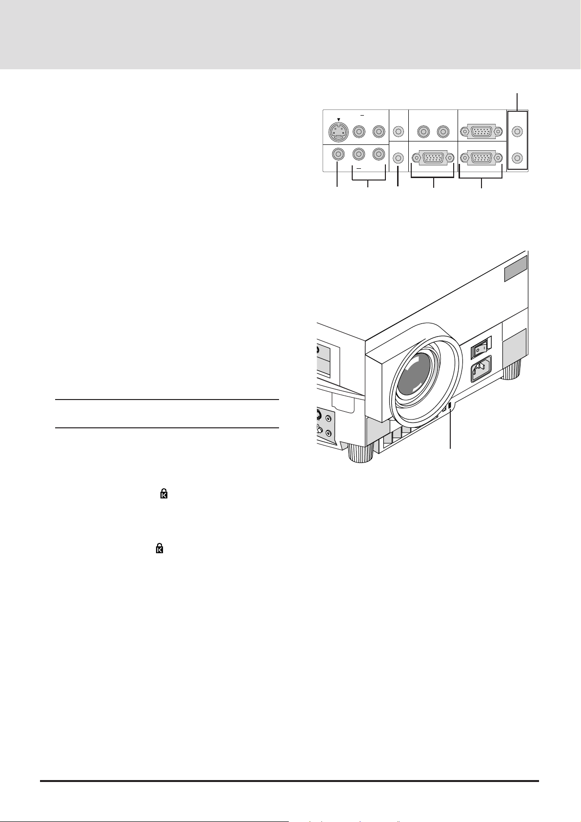
9 Remote Input Mini Jack
Connect your remote control cable here for wired operation.
Remote Output Mini Jack
This terminal enables you to loop up to 64 projectors with
the same remote control operation.
10 Video Input (RCA)
Connect a VCR, D VD player , laser disc player , or document
camera here to project video.
11 Left Channel/Mono Audio Input Jack (RCA)
This is your left channel audio input for stereo sound coming
from video equipment or audio system. This also serves as
your monaural audio input.
Right Channel Audio Input Jack
This is your right channel audio input for stereo sound.
12 Audio Output Mini Jack
Connect additional external speakers here to listen to audio
coming from the RGB 1, RGB 2, Video or S-Video input.
13 REMOTE 1 Connector (Mini D-Sub 15 pin)
Connect the control cable (available as an option) here when
the projector is used with the optional ISS-6020 or with
multiple projectors.
S-VIDEO INPUT AUDIO
L/MONO R L/MONO R
L/MONO R
VIDEO INPUT AUDIO
10
11
RGB 2
AUDIO
AUDIO
OUTPUT
12
RGB 1 AUDIO
REMOTE 1
13
REMOTE 2/PC
EXT
-
CTL
14
AC IN
9
REMOTE
INPUT
REMOTE
OUTPUT
NOTE: The ISS-6020/ISS-6020G Switcher is compatible with this projector.
14 External Control Connector (Mini D-Sub 15 pin)
This connector is for switch closure control or other external
controller.
15 Built-in Security Slot ( )
This security slot supports the MicroSaver® Security System.
MicroSaver® is a registered trademark of Kensington
Microware Inc. The logo is trademarked and owned by
Kensington Microw are Inc.
15
E-12
Page 13
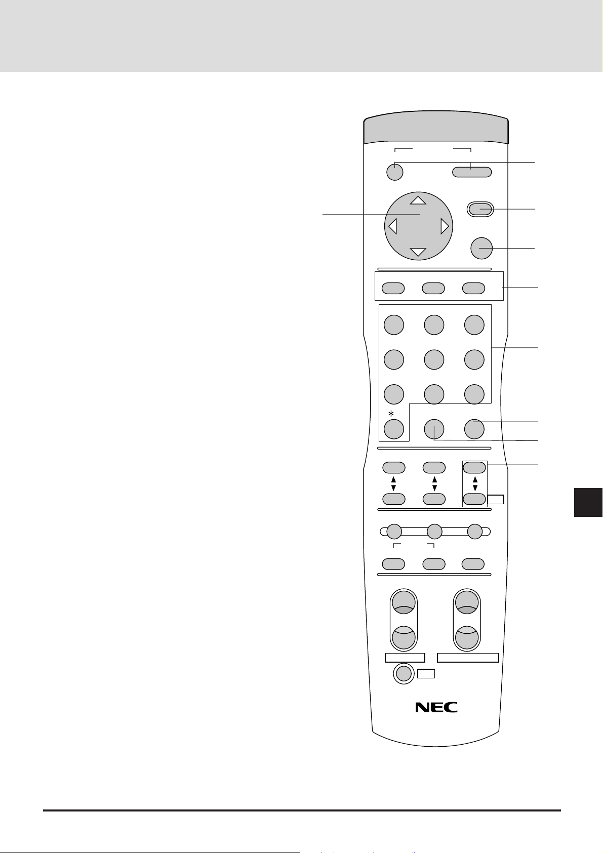
Remote Control Features
You can use your remote control with the cable or wireless to
operate your MultiSync GT2000/GT2000R LCD Projector.
If you want to use your remote control with the cable, connect
one end of the cable to the jack on the remote control and the
other end to the Terminal Panel.
OFF
POWER
ON
1
1 Power ON and OFF
If your main power switch on the front is turned on, you can
use this button to turn your projector on and off.
2 Menu
Press this button to call up the On-Screen Menu so you can
adjust and set the image.
T o return to the main menu from a submenu or to turn off the
main menu, press this button again.
3 Enter
This button activa tes items selected from the on-screen menu.
4 Cursor
Use this control to select items from the on-screen menu.
5 Input
Select your input source by pressing the RGB1, RGB2, or
VIDEO/S-VIDEO button. The VIDEO/S-VIDEO button
toggles between VIDEO and S-VIDEO. Also you can select
RGB or YCbCr directly by pressing CTL and RGB1(or RGB2)
buttons while you are in the RGB mode.
MENU
4
-
RGB1
ABC DEF
+
VIDEO/S-VIDEO
RGB2
ENTER
GHI
2
3
5
123
JKL MNO PQR
6
456
STU
7
,.
VWX YZ?
8
LOAD CLEAR
9
7
0
8
CONTRAST
SETUP NORMAL
VOLUMEBRIGHT
9
Adr.
DISPLAY
6 Number
Use one of these buttons to specify the memory location or
enter to name a signal during input registration.
7 Clear
Press this button to clear any adjustments in progress.
8 Load
Press any number button and then this button to activate settings you have stored previously from 01 to 100 of the memory
list.
9 Volume (Address with CTL)
This adjusts the volume of the built-in speaker.
Use the Volume(-) with the CTL button to display the Remote
Control Unit Address on screen to specify the remote control
address.
E-13
MUTE
PICTURE
FOCUS ZOOM
AUDIO
+
-
KEYSTONE
MAGNIFY/REDUCE
CTL
EXPAND
W
T
Page 14
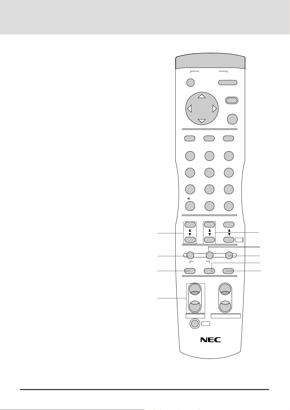
10 Contrast
Adjusts the image' s contrast for room conditions.
11 Brightness
Adjusts the image' s brightness for room conditions.
12 Setup
Press this button and then press the ENTER button to return to
the factory preset. Also you can search the memory by pressing the SETUP button and then the LOAD button.
13 Normal
This button returns the brightness, contrast or white balance
to its factory default settings.
OFF
RGB1
POWER
-
+
VIDEO/S-VIDEO
RGB2
ON
MENU
ENTER
14 Display
Press this button to identify the source being projected.
15 Picture Mute
This button turns off the image and the on-screen message for
a short period of time. Press again to restore it.
16 Audio Mute
This button temporarily shuts off or restores the sound.
17 Expand (Digital Zoom Function)
Press this button to turn the image enlargement control on or
off.
18 Focus (Keystone with CTL)
Press the (+) or (-) button to adjust the focus. (These buttons
are not available on GT2000R.)
Use these buttons with the CTL button to correct the ke ystone
(trapezoidal) distortion, and make the image square.
10
12
15
ABC DEF
GHI
123
JKL MNO PQR
456
STU
7
,.
VWX YZ?
8
LOAD CLEAR
9
0
CONTRAST
SETUP NORMAL
MUTE
PICTURE
FOCUS ZOOM
AUDIO
+
VOLUMEBRIGHT
DISPLAY
EXPAND
11
Adr.
13
14
16
17
W
E-14
18
-
KEYSTONE
CTL
T
MAGNIFY/REDUCE
Page 15
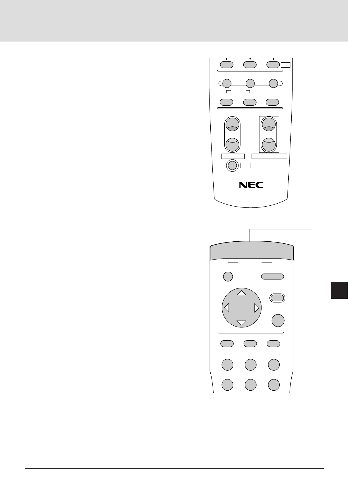
19 Zoom (Magnify/Reduce with CTL)
Press the (W) or (T) button to zoom in or zoom out. (These
buttons are not available on GT2000R.)
Use these buttons with the CTL button to adjust the image
size.
20 CTL(Control)
This button is pressed simultaneously with others (FOCUS,
ZOOM, V OLUME, RGB1, RGB2, KEYSTONE, MA GNIFY,
REDUCE, Adr. and direct selection of RGB and YCbCr) to
operate functions.
SETUP NORMAL
MUTE
PICTURE
FOCUS ZOOM
AUDIO
+
-
Adr.
DISPLAY
EXPAND
W
19
T
21 Remote Jack
Connect your remote control cable here for wired operation.
KEYSTONE
CTL
POWER
OFF
-
MAGNIFY/REDUCE
ON
MENU
+
ENTER
20
21
E-15
RGB1
ABC DEF
RGB2
VIDEO/S-VIDEO
GHI
123
JKL MNO PQR
456
Page 16
Remote Control Notes
• Use the remote control within a distance of about 7m (23feet)
and at an angle of 30˚ above, below, to the left and to the right of
the remote control sensor located at the front of the main unit.
• The remote control system may not function when direct
sunlight or strong illumination strikes the remote control sensor
of the main unit, or when there is an obstacle in the path.
• When remote control buttons are pressed and held, main unit
function keys may not operate.
• Do not subject to strong shock.
• Do not allow water or other liquid to splash on the remote
control. If the remote control gets wet, wipe it dry immediately.
• Avoid exposure to heat and steam.
• Remove the batteries from the remote control when the remote
control is not going to be used for a long period.
You cannot operate the projector using the remote control if:
• the remote ID is not set to [00].
• the remote ID is not the same as the projector ID.
See page E-43 for setting remote ID and page E-38 for setting
projector ID.
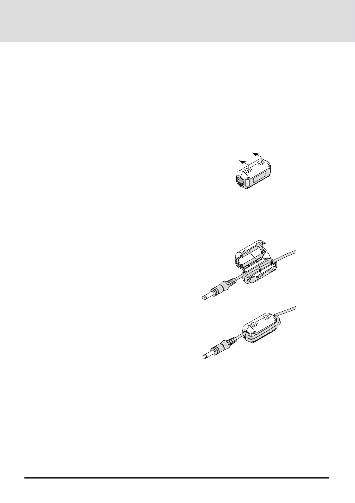
Attaching the supplied ferrite clamp
The ferrite clamp is provided with this projector in order to reduce
electromagnetic interference that may cause interference to radio
communication.
1. Push the catch and open the ferrite clamp.
2. Draw the remote cable through the hole and wind the remote
cable around the ferrite clamp two times, then close the ferrite
clamp. Place the ferrite clamp as closely to the end of the cable
that plugs into the projector as possible.
E-16
Page 17
INSTALLATION2
This section describes how to set up your MultiSync GT2000/
GT2000R LCD projector and how to connect video and audio
sources.
Setting Up Your MultiSync GT2000/
GT2000R LCD Projector
Your MultiSync GT2000/GT2000R LCD Projector is simple to
set up and use. But before you get started, you must first:
1. Determine the image size
2. Set up a screen or select a non-glossy white wall onto which
you can project your image.
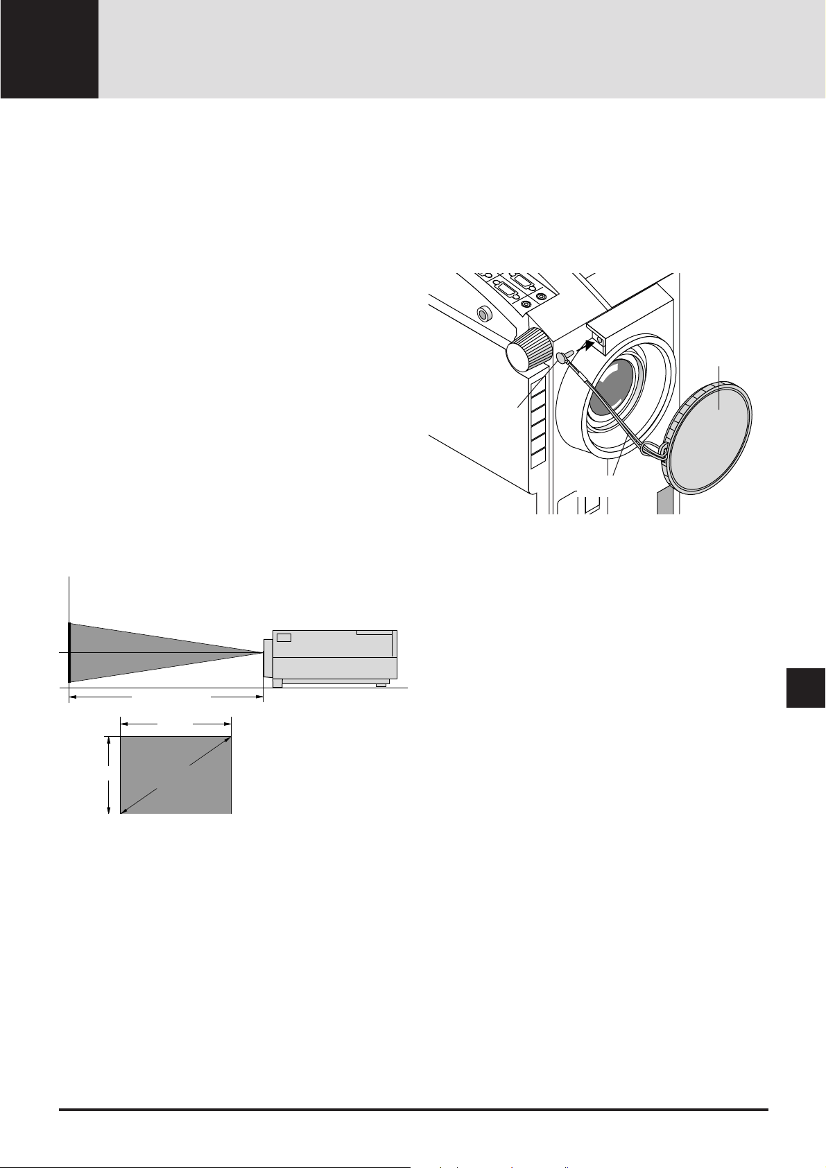
Attaching the lens cap to the lens hood with the supplied
string and rivet. (GT2000 only)
Carrying The LCD Projector Ensure that the power cord and
any other cables connecting to video sources are disconnected
before moving the projector. When moving the projector or
when it is not in use, cover the lens with the lens cap.
Selecting A Location The further your LCD projector is from
the screen or wall, the larger the image. The minimum size the
image can be is approximately 0.5 m (20") measured diagonally when the projector is roughly 1.0 m from the wall or
screen. The largest the image can be is 7.6 m (300") when the
projector is about 12.0 m from the wall or screen.
Projection distance
Width
Lens cap
Rivet
String
Height
Screen size
(diagonal)
E-17
Page 18
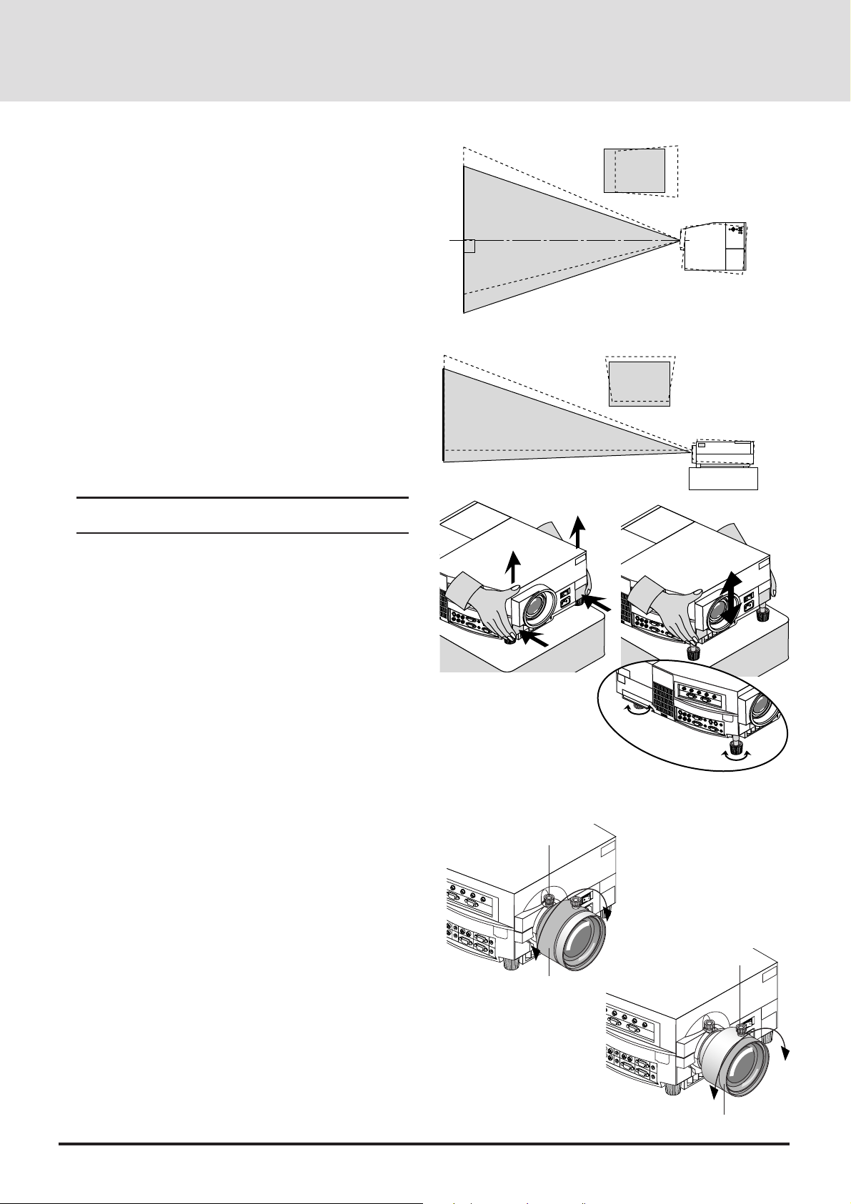
Using A Tabletop Or Cart
AC IN
1. Place your LCD projector on a flat level surface at the
optimal distance from the screen or wall so you realize the
size image you want. (Avoid having bright room lighting or
sun light directly on the screen or wall where you'll be
projecting the image.)
2. Connect the power cable, remove the lens cap and turn the
projector on. (If no input signal is available, the projector will
display a background image.)
3. Ensure that the projector is centered to the screen.
4. Move the projector left or right to center the image horizontally on the screen. (A)
5. To center the image vertically (B), lift the front edge of the
projector and press the buttons on the front of the projector,
just above the feet, to release the one-touch tilt feet. (There is
approximately 10.5˚ of up and down adjustment for the front
of the projector. )
6. If a trapezoidal distortion appears on the screen, use the
Focus and CTL buttons on the remote control or select the
Keystone from the Settings Menu under the Main menu.
Note: The keystone function is not available if no input signal
is present.
(A) Top view
screen
(B) Side view
screen
If necessary, adjust the front or rear feet so that the lens
surface is parallel to the screen. If you use the projector with
the screen tilted, the picture will be distorted. Each of the rear
feet height can be changed up to 5mm (0.2”).
7. Increase or reduce the size of the projected image by press-
ing the "Zoom" (+) or (–) buttons on the remote control or
top of the cabinet. (The zoom buttons are not available on
GT2000R.)
8. Adjust the f ocus by pressing the "Focus" (+) or (-) buttons on
the remote control or top of the cabinet.
(The focus buttons are not available on GT2000R. Use the
Focus/Floating lock knob and Focus/Floating ring to adjust
the focus on GT2000R. See below.)
To adjust the focus on GT2000R
1. Make sure that the focus lock knob and the floating lock knob
are tightened.
2. Adjust the focus at the center of the screen.
1) Loosen the focus lock knob, then grasp the focus ring and
rotate it.
2) Rotate the focus ring until the best center focus is obtained, and tighten the focus lock knob to lock it.
3. Adjust the focus at the edges of the screen.
1) Loosen the floating lock knob, then grasp the floating ring
and rotate it.
2) Rotate the floating ring until the best edge focus is obtained, and tighten the floating lock knob to lock it.
4. Select the "Projection" and choose "Rear-front" or "Rear
ceiling" to project an image from the rear.
Focus lock knob
Focus ring
Up
Down
Up
Down
AC IN
Floating lock knob
Floating ring
E-18
Page 19
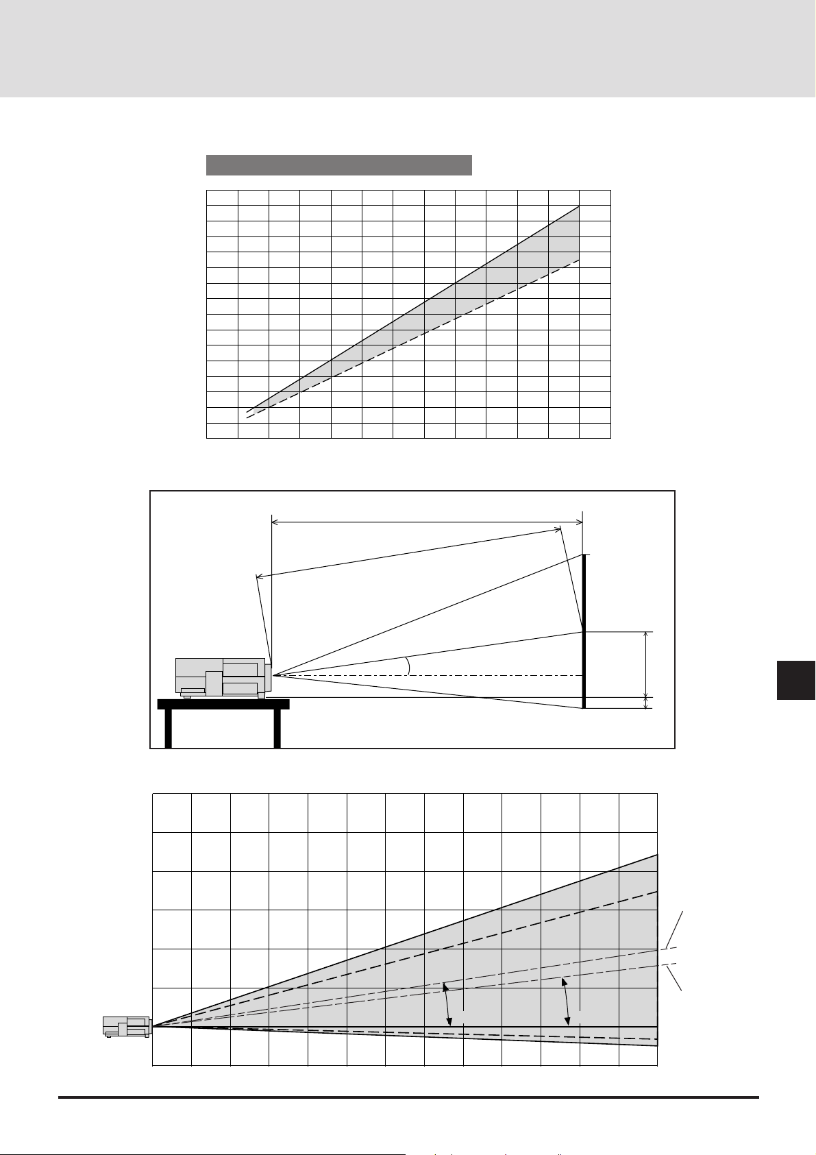
Distance Chart (GT2000)
300
240
200
160
120
100
Diagonal Screen Size (inch)
80
60
40
20
0 12345678910111213imj
Projection Distance and Image Size
Throw Distance
C
(m)
6
5
4
3
A
α
E
D
Center of WIDE
2
1
Center of TELE
-
8.6˚)
(8.9˚
(6.8˚-6.7˚)
0
1
0
12345678910111213 (m)
E-19
Page 20

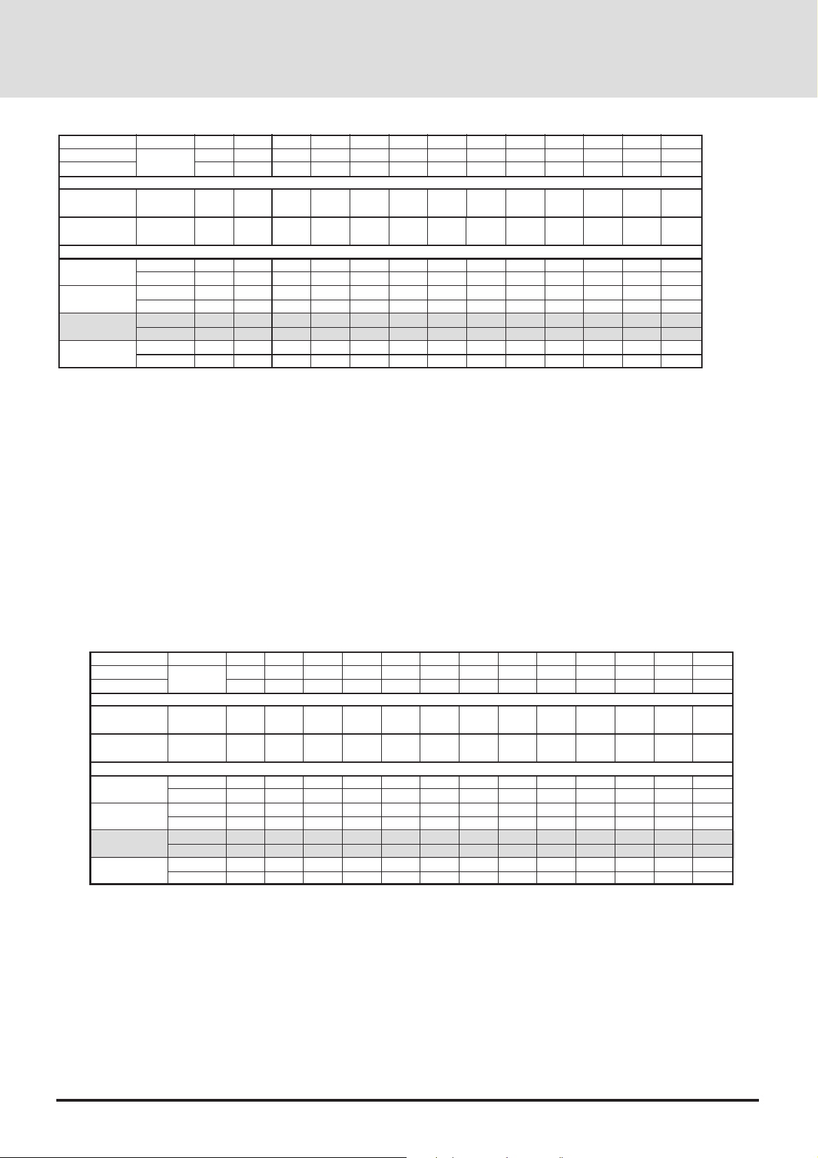
Standard Zoom Lens (Wide)
α
β (sin= α)
γ (cos= α)
Screen Size
H–Width
4 : 3 Diagonal
A
C
D
E
Degree
inch
mm
inch
mm
mm
inch
mm
inch
mm
inch
mm
inch
9.0
0.16
0.99
32
812.8
40
1016
1557
61.3
1537
60.5
-32
-1.2
336
13.2
8.9
0.15
0.99
48
1219.2
60
1524
2377
93.6
2349
92.5
-1
-0.0
458
18.0
8.8
0.15
0.99
56
1422.4
70
1778
2787
109.7
2754
108.4
14
0.6
519
20.4
8.8
0.15
0.99
64
1625.6
80
2032
3197
125.9
3160
124.4
29
1.1
580
22.9
8.8
0.15
0.99
72
1828.8
90
2286
3608
142.0
3566
140.4
44
1.7
641
25.3
8.7
0.15
0.99
80
2032
100
2540
4018
158.2
3971
156.4
60
2.3
702
27.7
8.7
0.15
0.99
96
2438.4
120
3048
4838
190.5
4783
188.3
90
3.5
825
32.5
8.7
0.15
0.99
120
3048
150
3810
6069
238.9
6000
236.2
135
5.3
1008
39.7
8.7
0.15
0.99
144
3657.6
180
4572
7300
287.4
7217
284.1
181
7.1
1191
46.9
8.6
0.15
0.99
160
4064
200
5080
8120
319.7
8028
316.1
211
8.3
1313
51.7
8.6
0.15
0.99
192
4876.8
240
6096
9761
384.3
9651
380.0
272
10.7
1557
61.3
8.6
0.15
0.99
216
5486.4
270
6858
10992
432.76
10868
427.9
317
12.5
1740
68.5
8.6
0.15
0.99
240
6096
300
7620
12223
481.2
12085
475.8
363
14.3
1923
75.7
Formulas (mm)
H mm=Horizontal Screen Width
C = [(53.22H) / 26.6]– 85.4
α= Tan-1(82H) / (26.62C)
A =C / cosα
E = 92.2 + [(82H) / 26.6]
D = (0.3752H) – E
A : Distance between the lens and the screen center
C : Horizontal throw distance between the screen surface and the lens
D : Vertical distance between the projector foot and the base of image
E : Vertical distance between the projector foot and the screen center
Standard Zoom Lens (Tele)
α
β (sin= α)
γ (cos= α)
Screen Size
H–Width
4 : 3 Diagonal
A
C
D
E
Degree
inch
mm
inch
mm
mm
inch
mm
inch
mm
inch
mm
inch
7.0
0.12
0.99
32
812.8
40
1016
2013
79.3
1999
78.7
-32
-1.2
336
13.2
6.8
0.12
0.99
48
1219.2
60
1524
3075
121.1
3053
120.2
-1
0.0
458
18.0
6.8
0.12
0.99
56
1422.4
70
1778
3606
142.0
3581
141.0
14
0.6
519
20.4
6.8
0.12
0.99
64
1625.6
80
2032
4137
162.9
4108
161.7
29
1.1
580
22.9
1828.8
2286
4668
183.8
4635
182.5
6.8
0.12
0.99
72
90
44
1.7
641
25.3
6.7
0.12
0.99
2032
100
2540
5199
204.7
5163
203.3
2.3
702
27.7
Formulas (inch)
H inch=Horizontal Screen Width
C = [(50.72H)– 85.4] / 25.4
α= T an-1(82H) / (26.62C)
A =C / cosα
E = [92.2 + (7.62H ) ]/ 25.4
D = (0.3752H) – E
6.7
120
150
135
5.3
6.7
0.12
0.99
144
3657.6
180
4572
9446
371.9
9382
369.4
181
7.1
1191
46.9
6.7
0.12
0.12
0.99
0.99
96
80
2438.4
60
120
3048
6260
246.5
6217
244.8
90
3.5
825
32.5
3048
3810
7853
309.2
7800
307.1
1008
39.7
6.7
0.12
0.99
160
4064
200
5080
10508
413.7
10436
410.9
211
8.3
1313
51.7
6.7
0.12
0.99
192
4876.8
240
6096
12631
497.3
12546
493.9
272
10.7
1557
61.3
6.7
0.12
0.99
216
5486.4
270
6858
14224
560.0
14128
556.2
317
12.5
1740
68.5
6.6
0.12
0.99
240
6096
300
7620
15817
622.7
15710
618.5
363
14.3
1923
75.7
Formulas (mm)
H mm=Horizontal Screen Width
C = {[(53.22H )/ 26.6] – 85.4}21.3
α= T an-1(82H) / (26.62C)
A =C / cosα
E = 92.2 + [(82H) / 26.6]
D = (0.3752H) – E
A : Distance between the lens and the screen center
C : Horizontal throw distance between the screen surface and the lens
D : Vertical distance between the projector foot and the base of image
E : Vertical distance between the projector foot and the screen center
E-20
Formulas (inch)
H inch=Horizontal Screen Width
C = {[(50.72H)– 85.4]21.3} / 25.4
α= T an-1(82H) / (26.62C)
A =C / cosα
E =[ 92.2 + (7.62H )] / 25.4
D = (0.3752H) – E
Page 21
WARNING
•
Only use your LCD projector on a solid, level surface. If the projector falls to the g round, you can be injured and the projector severely damaged.
• Do not use the LCD projector where temperatures vary greatly. The projector must be used at temperatures between 0˚C and 40˚C.
• Do not expose the LCD projector to moisture, dust, or smoke. This will de grade image perfor mance.
• Ensure that you have adequate ventila tion around your LCD projector so that heat can dissipate. Do not cover the vents on the side
or the front of the projector.
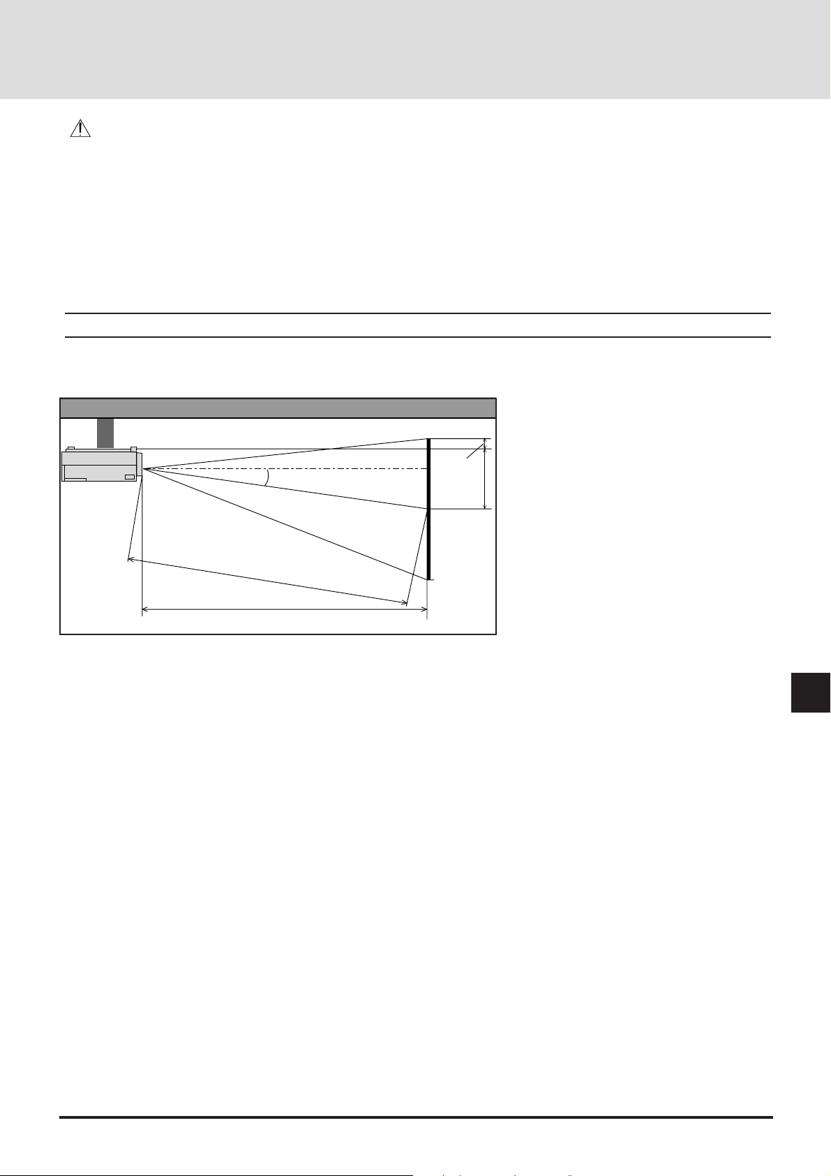
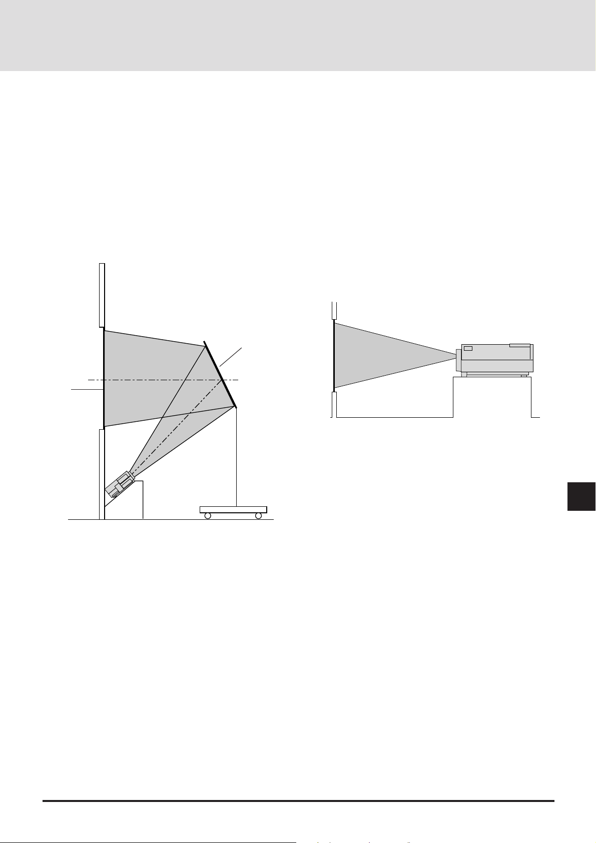
Ceiling Installation
Installing your LCD Projector on the ceiling must be done by a qualified technician. Contact your NEC dealer for more information.
Do not attempt to install the projector yourself.
NOTE : Distances may vary ±5%.
F
α
B
A
C
A : Distance between the lens and the screen center
B : Vertical distance between the projector bottom and the screen center
C : Horizontal throw distance between the screen surface and the lens
F : Vertical distance between the projector bottom and the top of image
E-21
Page 22
Standard Zoom Lens (Wide)
α
β (sin= α)
γ (cos= α)
Degree
9.0
0.16
0.99
8.9
0.15
0.99
8.8
0.15
0.99
8.8
0.15
0.99
8.8
0.15
0.99
8.7
0.15
0.99
8.7
0.15
0.99
8.7
0.15
0.99
8.7
0.15
0.99
8.6
0.15
0.99
8.6
0.15
0.99
8.6
0.15
0.99
8.6
0.15
0.99
Screen Size
H–Width
4 : 3 Diagonal
A
B
C
F
inch
mm
inch
mm
mm
inch
mm
inch
mm
inch
mm
inch
32
812.8
40
1016
1557
61.3
329
13.0
1537
60.5
-25
-1.0
48
1219.2
60
1524
2377
93.6
451
17.8
2349
92.5
6
0.2
56
1422.4
70
1778
2787
109.7
512
20.2
2754
108.4
21
0.8
64
1625.6
80
2032
3197
125.9
573
22.6
3160
124.4
36
1.4
72
1828.8
90
2286
3608
142.0
634
25.0
3566
140.4
51
2.0
80
2032
100
2540
4018
158.2
695
27.4
3971
156.4
67
2.6
96
2438.4
120
3048
4838
190.5
818
32.2
4783
188.3
97
3.8
Formulas (mm)
H mm=Horizontal Screen Width
C = [(53.22H) / 26.6]– 85.4
α= Tan-1(82H) / (26.62C)
A =C / cosα
B= 85.2 + [(82H) / 26.6]
F = (0.3752H) – B
A : Distance between the lens and the screen center
B : Vertical distance between the projector bottom and the screen center
C : Horizontal throw distance between the screen surface and the lens
F : Vertical distance between the projector bottom and the top of image
160
200
51.4
218
8.6
192
4876.8
240
6096
9761
384.3
1550
61.0
9651
380.0
279
11.0
120
3048
150
3810
6069
238.9
1001
39.4
6000
236.2
142
5.6
144
3657.6
180
4572
7300
287.4
1184
46.6
7217
284.1
188
7.4
4064
5080
8120
319.7
1306
8028
316.1
Formulas (inch)
H inch=Horizontal Screen Width
C = [(50.72H)– 85.4] / 25.4
α= T an-1(82H) / (26.62C)
A =C / cosα
B = [85.2 + (7.62H )] / 25.4
F = (0.3752H )– B
216
5486.4
270
6858
10992
432.76
1733
68.2
10868
427.9
324
12.8
240
6096
300
7620
12223
481.2
1916
75.4
12085
475.8
370
14.6
Standard Zoom Lens (Tele)
α
β (sin= α)
γ (cos= α)
Screen Size
H–Width
4 : 3 Diagonal
A
B
C
F
Formulas (mm)
H mm=Horizontal Screen Width
C = [(53.22H / 26.6) – 85.4]21.3
α= T an-1(82H) / (26.62C)
A =C / cosα
B = 85.2 + [(82H )/ 26.6]
F = (0.3752H) – B
Degree
inch
mm
inch
mm
mm
inch
mm
inch
mm
inch
mm
inch
7.0
0.12
0.99
32
812.8
40
1016
2013
79.3
329
13.0
1999
78.7
-25
-1.0
6.8
0.12
0.99
48
1219.2
60
1524
3075
121.1
451
17.8
3053
120.2
6
0.2
6.8
0.12
0.99
56
1422.4
70
1778
3606
142.0
512
20.2
3581
141.0
21
0.8
6.8
0.12
0.99
64
1625.6
80
2032
4137
162.9
573
22.6
4108
161.7
36
1.4
6.8
0.12
0.99
72
1828.8
90
2286
4668
183.8
634
25.0
4635
182.5
51
2.0
6.7
0.12
0.99
80
2032
100
2540
5199
204.7
695
27.4
5163
203.3
67
2.6
6.7
0.12
0.99
96
2438.4
120
3048
6260
246.5
818
32.2
6217
244.8
97
3.8
6.7
0.12
0.99
120
3048
150
3810
7853
309.2
1001
39.4
7800
307.1
142
5.6
0.12
0.99
3657.6
4572
9446
371.9
1184
46.6
9382
369.4
6.7
144
180
188
7.4
6.7
0.12
0.99
160
4064
200
5080
10508
413.7
1306
51.4
10436
410.9
218
8.6
Formulas (inch)
H inch=Horizontal Screen Width
C = {[(50.72H)– 85.4]21.3} / 25.4
α= T an-1(82H) / (26.62C)
A =C / cosα
B= [85.2 + (7.62H )] / 25.4
F = (0.3752H) – B
6.7
0.12
0.99
192
4876.8
240
6096
12631
497.3
1550
61.0
12546
493.9
279
11.0
6.7
0.12
0.99
216
5486.4
270
6858
14224
560.0
1733
68.2
14128
556.2
324
12.8
6.6
0.12
0.99
240
6096
300
7620
15817
622.7
1916
75.4
15710
618.5
370
14.6
A : Distance between the lens and the screen center
B : Vertical distance between the projector bottom and the screen center
C : Horizontal throw distance between the screen surface and the lens
F : Vertical distance between the projector bottom and the top of image
E-22
Page 23
GT2000R
If your projector is mounted on the ceiling and your image is
upside down, use the “Menu” and “Select” buttons on your
projector cabinet or (▲) (▼) buttons on your remote control to
correct the orientation. (See page E-39.)
Reflecting The Image
Using a mirror to reflect your LCD projector's image enables
you to enjoy a much larger image. Contact your NEC dealer if
you need a mirror.
If you're using a mirror and your image is inverted, use the
“Menu” and “Select” buttons on your projector cabinet or (▲)
(▼) buttons on your remote control to correct the orientation.
(See page E-39.)
Mirror
Screen
Rear Screen Projection
Y ou can use your MultiSync GT2000R LCD projector to project
an image from the rear onto a transparent screen. The distance
the projector must be from the screen is the same as if you were
projecting the image from the front. Contact your NEC dealer if
you need a transparent screen.
If you're projecting the image from the rear and your image is
inverted, use the “Menu" and "Select" b uttons on your projector
cabinet or (▲) (▼) buttons on your r emote control to correct the
image. (See page E-39.)
E-23
Page 24
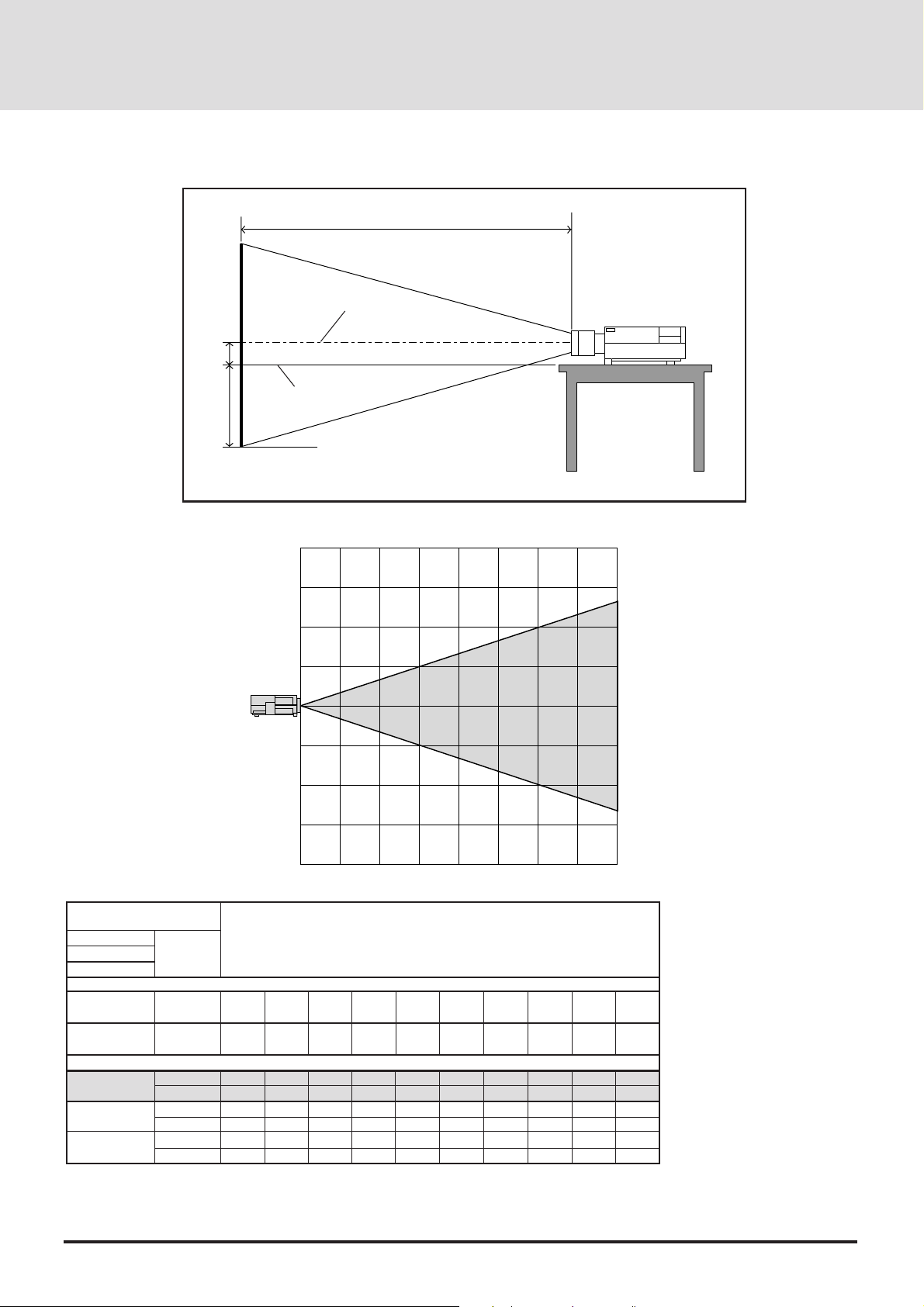
GT2000R
C
Screen center line
E
D
Desktop line
Screen Bottom
(m)
4
3
2
1
0
1
GT2000R
2
3
4
0
12345678 (m)
Degree
72
1828.8
90
2286
2009
79.1
602
23.7
84
3.3
0.0
0.0
1.0
80
2032
100
2540
2244
88.3
678
26.7
84
3.3
2438.4
α
β (sin= α)
γ (cos= α)
Screen Size
H–Width
4 : 3 Diagonal
A (=C)
D
E
inch
mm
inch
mm
mm
inch
mm
inch
mm
inch
32
812.8
40
1016
833
32.8
221
8.7
84
3.3
48
1219.2
60
1524
1303
51.3
373
14.7
84
3.3
56
1422.4
70
1778
1539
60.6
449
17.7
84
3.3
64
1625.6
80
2032
1774
69.8
525
20.7
84
3.3
C : Horizontal throw distance between the screen surface and the lens
D : Vertical distance between the projector foot and the base of image
E : Vertical distance between the projector foot and the screen center
96
120
3048
2714
106.8
830
32.7
84
3.3
120
3048
150
3810
3419
134.6
1059
41.7
84
3.3
144
3657.6
180
4572
4124
162.4
1287
50.7
84
3.3
160
4064
200
5080
4594
180.9
1440
56.7
84
3.3
Formulas (mm)
H mm=Horizontal Screen Width
C = {[(H/ 26.6) – 30.77]230.8} + 841.3
D = (0.3752H) – 84.2
E = 84.2
Formulas (inch)
H inch=Horizontal Screen Width
C = {[(0.952H)– 30.8]21.21} + 33.1
D = (0.3752H) – 3.3
E =3.3
E-24
Page 25
S-VIDEO INPUT AUDIO
VIDEO INPUT AUDIO
REMOTE 1
RGB 1 AUDIO
REMOTE 2/PC
EXT
-
CTL
RGB 2
AUDIO
AUDIO
OUTPUT
REMOTE
OUTPUT
REMOTE
INPUT
L/MONO R L/MONO R
L/MONO R
R/Cr G/YB
/
Cb
H
/
HV V
RGB
INPUT 2
RGB
OUTPUT
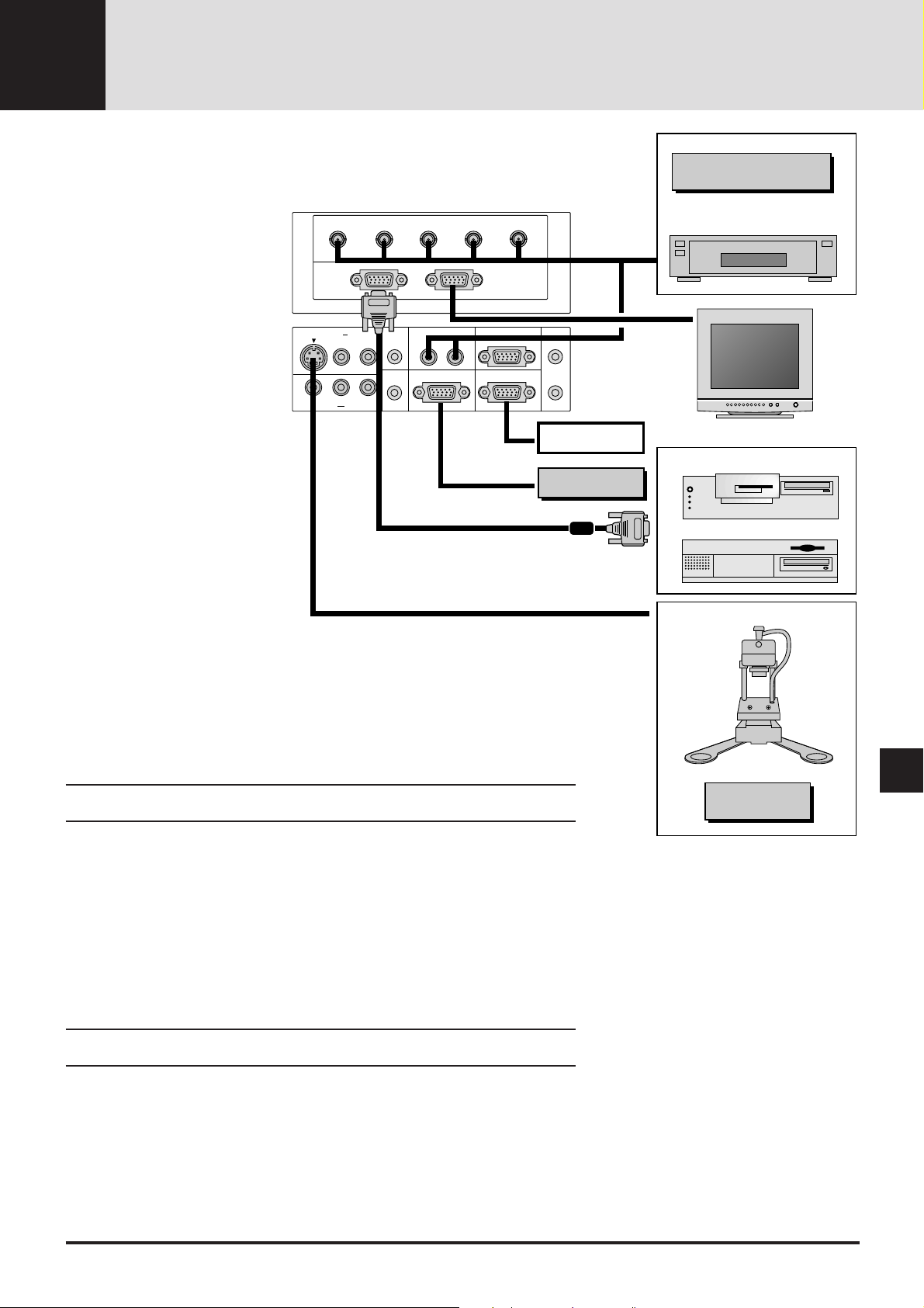
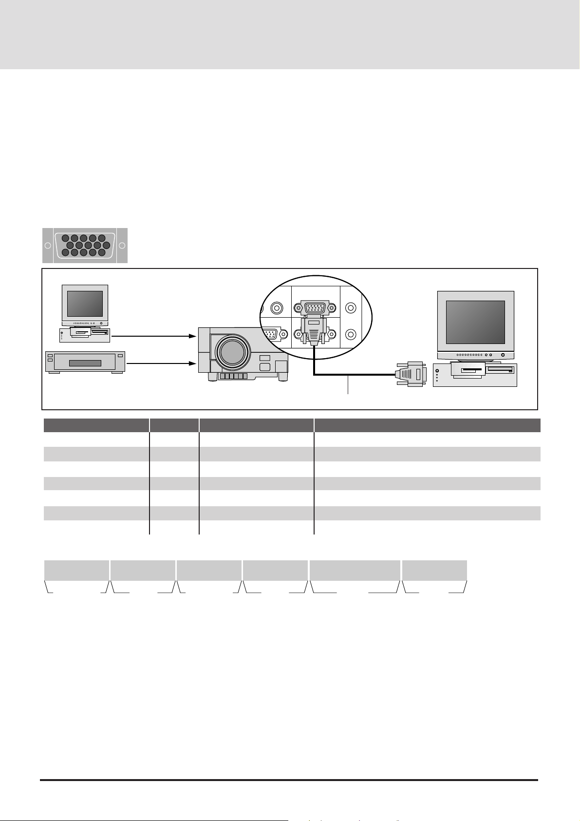
CONNECTIONS3
Wiring Diagram
Connecting Your PC Or
Macintosh Computer
Connecting your PC or Macintosh
computer to your GT2000/
GT2000R Projector will enable you
to project your computer's screen
image for an impressive presentation.
T o connect to a PC or Macintosh,
simply:
1. Turn off the power to your projector and computer.
2. Use the signal cable that's supplied to connect your PC or
Macintosh computer to the projector.
3. Turn on the projector and the
computer.
4. If the projector goes blank after a
period of inactivity, it may be
caused by a screen saver installed on the computer you've
connected to the projector.
IPS-4000/
IPS4000Q
DVD Player or LaserDisc Player
Monitor
External Control
IBM VGA or Compatibles
ISS-6020
Macintosh
Connecting Your Document Camera
You can connect your MultiSync GT2000/GT2000R LCD Projector to a document camera. To
do so, simply:
1. Turn off the power to your LCD projector and document camera.
2. Use a standard video cable to connect your document camera to the Video input on your
projector.
3. Turn on the LCD projector and the document camera.
NOTE: Refer to your document camera's owner's manual for more information about your
camera's video output requirements .
Connecting Your VCR Or Laser Disc Player
Use common RCA cables (not provided) to connect your VCR or laser disc player to your
MultiSync GT2000/GT2000R LCD Projector. To make these connections, simpl y:
1. Turn off the power to your LCD projector and VCR or laser disc player.
2. Connect one end of your RCA cable to the video output connector on the back of your VCR
or laser disc player, connect the other end to the V ideo input on your projector . Use standard
RCA audio patch cords to connect the audio from your VCR or laser disc player to your
projector (if your VCR or laser disc player has this capability). Be careful to keep your right
and left channel connections correct for stereo sound.
3. Turn on the LCD projector and the VCR or laser disc player.
NOTE: Refer to your VCR or laser disc player owner's manual for more information about your
equipment's video output requir ements.
Connecting An External Monitor
You can connect a separate, external monitor to your LCD projector to simultaneously view on
a monitor the image you're projecting. To do so:
1. Turn off the power to your LCD projector, monitor and computer, document camera or
video source.
2. Use a 15-pin cable to connect your monitor to the RGB Monitor Output (Mini D-Sub 15
pin) connector on your LCD projector.
3. Turn on the LCD projector, monitor and the computer, document camera or video source.
Document Camera
VCR/ Laser disc player
E-25
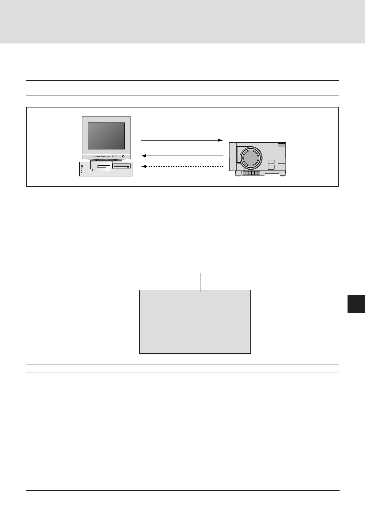
Page 26
PC Control
REMOTE 2/PC
EXT
-
CTL
REMOTE
OUTPUT
REMOTE
INPUT
Interface
An RS-232C cable enables you to use your PC as a controller for your projector.
* RS-232C (Straight cable)
* Baud rate: ................................ 9600 bps
* Data length:............................. 8 bits
* Parity: ...................................... Odd parity
* Stop bit: ................................... 1 bit
* Communications procedure: ... Full duplex
REMOTE 2/PC Connector
4
512
3
9
10 67
8
14
15 1112
13
To RS232C
Signal source
RS232C straight cable
Pin No.
9, 15
6
7
12
8
1, 2
3-5, 10, 11, 13, 14
I/O
I
O
I
O
-
-
Signal Name
Signal Ground
Receive Data
Transmit Data
Clear To Send
Request T o Send
-
Not Connected
Ground
Data reception
Data transmission
Reception interrupt
Transmission interrupt
Used iside the projector (Should always be left open)
Not used
Control Data Format
8 bits 8 bits 8 bits 8 bits 8 bits
Command
specification code
Unit
address
* Command specification code: This code specifies whether the
command is a single control command or a multiple control
command.
A single control command (C0H) is valid for only the projector
specified by the unit address.
A multiple control command (C1H) is valid for all projectors
which receive the command, regardless of the unit address. Note
that only projectors in agreement with the unit address will
return an ACK.
* Unit address: This code specifies the ID of the projector (0-64).
You can select the [Settings Menu]->[Projector ID] under the
main menu and specify the ID of projector.
For a single projector, the ID should be set at 0.
Function
number
Data
length
•••••••••
Data
* Function number: The function's identification code.
* Data length: This specifies the number of bytes of data (not
including CKS).
* Data: The parameters attached to the function.
* CKS (check sum): The lower-order 8 bits of the calculation
results from the first byte (i.e., the command specification code)
to the byte in front of CKS.
Function
CKS
E-26
Page 27
Command Communications Sequence
When a command sent from the personal computer has been correctly received by the projector, an "ACK" is returned for the command.
When the command has not been received correctly, a "Receive Error" is sent back. An invalid command will cause a "Command Error".
Note: When an"ACK" from the projector is not confirmed and the next command is received by the projector, an error in
communication can result.
Command
ACK
Receive error
(1) Command (PC to Projector)
Command specification code Unit address Function number Data length Data .............. CKS
(2) ACK (Projector to PC)
*When there is return data
Command specification code Unit address Function number Data length Data ............. CKS
*When there is no return data
Command specification code Unit address Function number 00H CKS
(3) Receive error (Projector to PC)
Command specification code Unit address 00H 01H EC (Error code) CKS
EC (Receive Error Codes)
02H : Command error
04H : Checksum error
08H : Busy
10H : Parameter error
20H : Run error
40H : Receiving error on
Projector
Note: For a complete PC Control Command Reference, see page E-83.
E-27
Page 28

Connections with the ISS-6020
Connections with One ISS-6020 Switcher
Connecting your GT2000/GT2000R projector to a single ISS-6020 switcher (using a cable available separately) delivers a
series of benefits:
• You can handle input from ten sources simultaneously.
• The ISS-6020 can be controlled by the remote provided with your GT2000/GT2000R or with the buttons on the projector
cabinet. (Source selection without the use of a CTL-6010 cable must be performed with the GT2000 hand held remote
control.)
• “Channel Memory” enables you to set optimal settings individually for as many as ten different sources.
MENU
STATUS
POWER
ON / OFF
SELECT
-
ENTER
ZOOM FOCUS
+
+
-+-
When the GT2000/GT2000R is used with the ISS-6020 switcher in
bundled operation, the indicator LED (STATUS) lights green after
switching on the GT2000/GT2000R power.
System Connections Diagram
Lights green
1
ISS-6020
10
1
1
GT2000
GT2000R
1
indicates the REMOTE 1 connector
Control cable
Video signal cable
To use the ISS-6020 with the GT2000/GT2000R, do the following:
* Select the [Settings Menu]→[Switcher Control]→[SW 1 Level] under the main menu.(The factory default setting is
"Standalone".)
* Select the [Memory]->[Channel Memory] under the main menu and perform the Signal Entry.
* When using the projector with the external equipment, select the [Memory]->[User Memory] under the main menu and
perform the Signal Entry.
* Select the [Switcher] menu from the main menu and make some adjustments such as RGB gain, color, tint, sharpness,
volume and audio control.
DIP Switch Settings
To use GT2000/GT2000R with an ISS-6020, the DIP switch (S8601) located inside the ISS-6020 System Control module
should be set as shown here. (Leave the pins 5 to 7 in their original factory settings.)
OPEN
1 2 3 4 5 6 7 8
SHORT
Pin No.8 must be set at "OPEN".
* For more details about operating the ISS-6020, please see y our ISS-6020 user's manual
E-28
Page 29

Connections with Multiple ISS-6020 Switcher
You can accommodate as many as 100 sources by connecting your GT2000/GT2000R to one ISS-6020 switcher that acts as
"master" and ten more switchers that are "slaves."
To connect several ISS-6020s, the "Switcher Control" on the "Settings Menu" should be set to "SW 2 Level" for multiple
projectors. (See page E-38.)
Note: The more ISS-6020 switc her s that are connected, the more time is needed for the projector to start up.
System Connections Diagram
10
2
1
2
3
ISS-6020
(Master)
1
1
GT2000
GT2000R
Control cable
10
10
10
1
ISS-6020
(Slave 1)
1
ISS-6020
(Slave 2)
1
ISS-6020
(Slave 3)
1
2
1
2
1
2
Image signal cable
10
1
ISS-6020
(Slave 10)
1
2
1
indicates connection to the REMOTE 1 connector
2
indicates connection to the REMOTE 2 connector
DIP Switch Settings
To use the GT2000/GT2000R with two ISS-6020 switchers or more, the DIP switch (S8601) inside the ISS-6020 System
Control module should be set as shown here. The pin 8 should be set to "OPEN". (Leave the pins 5 to 7 in their original factory
settings.)
Master
Slave 1
Slave 2
OPEN
1 2 3 4 5 6 7 8
SHORT
OPEN
1 2 3 4 5 6 7 8
SHORT
OPEN
1 2 3 4 5 6 7 8
SHORT
Slave 3
Slave 4
Slave 5
Slave 6
OPEN
1 2 3 4 5 6 7 8
SHORT
OPEN
1 2 3 4 5 6 7 8
SHORT
OPEN
1 2 3 4 5 6 7 8
SHORT
OPEN
1 2 3 4 5 6 7 8
SHORT
Slave 7
Slave 8
Slave 9
Slave 10
OPEN
1 2 3 4 5 6 7 8
SHORT
OPEN
1 2 3 4 5 6 7 8
SHORT
OPEN
1 2 3 4 5 6 7 8
SHORT
OPEN
1 2 3 4 5 6 7 8
SHORT
Slide Switch Settings
Set the slide switch located inside the ISS-6020 system control module to the RS-422 side.
* Select the [Settings Menu]→[Switcher Control]→[SW 2 Level] under the main menu.
* Select the [Memory]→[Channel Memory] under the main menu and perform the Signal Entry.
* When using the projector with the external equipment, select the [Memory]→[User Memory]
under the main menu and perform the Signal Entry.
* Select the [Switcher] menu from the main menu and make some adjustments such as RGB gain,
color, tint, sharpness, volume and audio control.
E-29
RS-422
RS-232C
Page 30

Connecting Multiple Projectors
As many as 64 projectors can be connected together and controlled by the same PC. For more information about managing multiple
projectors. See page E-31.
External equipment
(Max.10 units)
To REMOTE2
RGB interface
(Signal distributor)
RS232C Cable
Control Cable
Control Cable
To REMOTE 2/PC
To REMOTE 1
To REMOTE 2/PC
To REMOTE 1
To REMOTE 2/PC
To REMOTE 1
To REMOTE 2/PC
To REMOTE 1
ID=01
ID=02
ID=63
ID=64
To RGB/YCbCr input 1
Video Signal
To RGB/YCbCr input 1
To RGB/YCbCr input 1
* When you connect multiple projectors, a different ID number (from 00 to 64) must be assigned to each. To specify an ID of the
projector, select the [Settings Menu]→[Projector ID] under the main menu and enter the ID number.
* The sync termination must be set at "75Ω". To do this, select the [Settings Menu]→[Sync Termination] under the main menu and
select "75Ω".
* The ID number "1" should be assigned to the projector which is connected with a PC and "64" to the projector which is connected
with the ISS-6020 Switcher.
* When connecting the ISS-6020 Switcher with a control cable in connection of multiple projectors, connect the ISS-6020 Switcher
to the last projector with an unused REMOTE 1 connector. The ID number of the last projector should be set at 64.
Also you must set the "RS-232C/RS-422" slide switch inside the ISS-6020 system control module to "RS-422".
E-30
Page 31

Operating Multiple Projector with Remote Control
REMOTE 2/PC
EXT
-
CTL
REMOTE
OUTPUT
REMOTE
INPUT
You can operate as many as 64 projectors with the same remote control in wireless operation.
T o do so:
1. Select [Settings Menu]→[Projector ID] under the main menu and assign an ID number to each projector.
2. Specify the remote ID number to the projector to be used. To do, press and hold the CTL and press Adr button to enter the ID
number.
You can operate the projector assigned the same ID number as the remote address.
Projector ID= 01
Projector ID= 02 Projector ID= 03
Remote Address = 03
You can daisy-chain as many as 64 projectors and operate them separately with the same remote control in wired operation.
T o do so:
Use the remote control cable supplied to connect the Remote Control Output of one projector to the Remote Control Input of the next
until all the projectors are connected.
Remote Address = 03
Projector ID= 01
Projector ID= 02 Projector ID= 03
E-31
Page 32
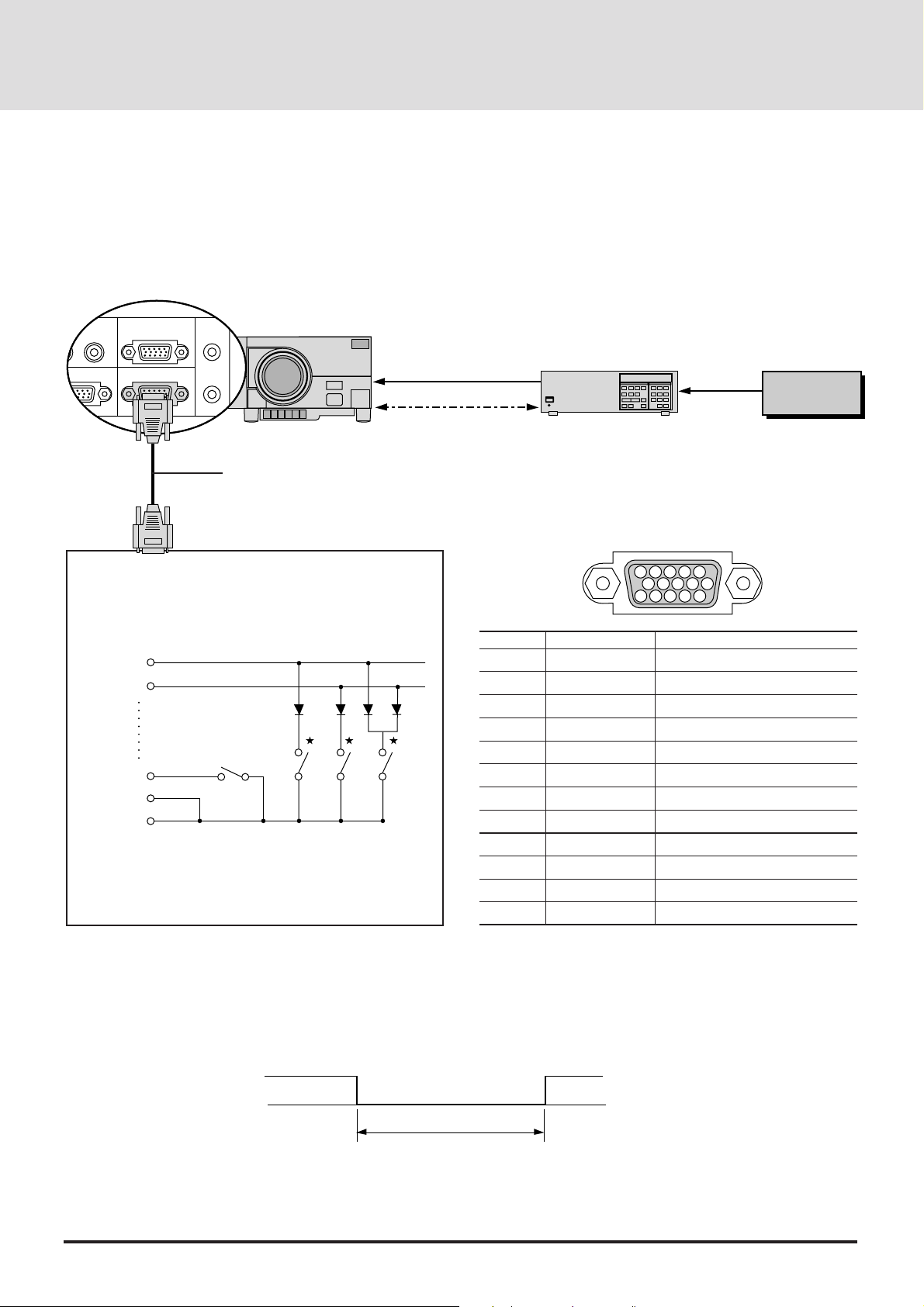
REMOTE 2/PC
EXT
-
CTL
REMOTE
OUTPUT
REMOTE
INPUT
External Control
T o turn your projector on and off, to turn the mute on or off and to switch video sources, use the EXT-CTL connector.
* When using the external control, do the following:
1. Select the [Settings Menu]→[Ext.Control] under the main menu and select "On".
2. Set the pin 8 of the DIP switch (S8601) to "SHORT". The DIP switch is loca ted inside the ISS-6020 system control module.
Control Cable
Console Control Unit Setup Example
* This example is when power is ON and channel 1, 2, and
3 switching is activated. The circuit setup is valid when
the contacts of any of the switches are closed.
/
EX CO
8
EX C1
3
EXT-CTL
EX PW
14
15
5
EX EN
POWER
1ch
2ch 3ch
Small signal Silicone diodes are used.
* Switchs cannot be pressed simultaneously.
* Channel number means slot number on the ISS-6020.
Video Signal
ISS-6020
Video Signal
To Slot 1-10
To REMOTE 1To REMOTE 1
EXT-CTL Pin Assignments
51423
10
Pin No. SignalName Function
15 Signal Ground Ground
14 EX EN External control enable
5 EX PW Power ON/OFF
10 EX MT Mute ON/OFF
8 EX C/O Source selection data bit
3 EX C1 Source selection data bit
9 EX C2 Source selection data bit
4 EX C3 Source selection data bit
11 EX C4 Source selection data bit
13 EX C5 Source selection data bit
12 EX C6 Source selection data bit
1,2,6,7 Not connected Not used
6978
1112131415
External equipment
(Max.10 units)
Control Method
When the EX EN signal is low, the projector periodically polls the setting data.
EX EN
Period of external control validity
(300 ms or more)
E-32
Hi
Lo
Page 33
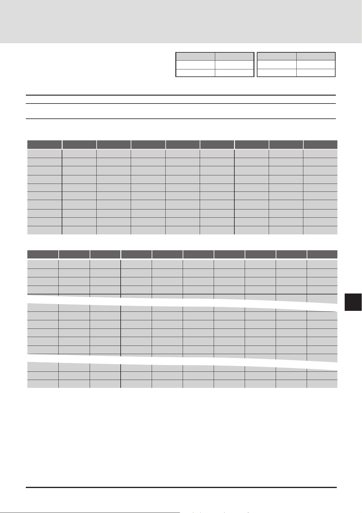
Setting The Data
When the EX PW pin is low, the power is on; when high, the
power is off.
Power
ON
OFF
EX PW
Low
High
Picture Mute
ON
OFF
EX MT
Lo
Hi
When the EX MT pin is low, Picture Mute is on; when high,
Picture Mute is off.
Note: Channel settings are only valid when the ISS-6020 is connected.
Note: If a channel is switched to another using the remote control when the external contr ol is valid, the channel is for ced to swit ch to
the one set by the external contr ol.
Connecting A Single ISS-6020 Switcher
Slot
1
2
3
4
5
6
7
8
9
10
Channel Number
1
2
3
4
5
6
7
8
9
0
EX C6
Hi
Hi
Hi
Hi
Hi
Hi
Hi
Hi
Hi
Hi
Connecting Multiple ISS-6020 Switchers
Master Slot
1
1
1
1
9
9
9
10
10
Slave Slot
1
2
3
4
8
9
10
1
2
Channel Number
11
12
13
14
98
99
90
01
02
EX C6
Hi
Hi
Hi
Hi
Lo
Lo
Lo
Hi
Hi
EX C5
Hi
Hi
Hi
Hi
Hi
Hi
Hi
Hi
Hi
Hi
EX C5
Hi
Hi
Hi
Hi
Lo
Lo
Hi
Hi
Hi
EX C4
Hi
Hi
Hi
Hi
Hi
Hi
Hi
Hi
Hi
Hi
EX C4
Hi
Hi
Hi
Hi
Hi
Hi
Lo
Hi
Hi
EX C3
Hi
Hi
Hi
Hi
Hi
Hi
Hi
Lo
Lo
Hi
EX C3
Lo
Lo
Lo
Lo
Hi
Hi
Lo
Hi
Hi
EX C2
Hi
Hi
Hi
Lo
Lo
Lo
Lo
Hi
Hi
Hi
EX C2
Hi
Lo
Lo
Lo
Hi
Hi
Hi
Hi
Hi
EX C1
Hi
Lo
Lo
Hi
Hi
Lo
Lo
Hi
Hi
Hi
EX C1
EX C0
Lo
Hi
Lo
Hi
Lo
Hi
Lo
Hi
Lo
Hi
EX C0
Lo
Hi
Hi
Lo
Lo
Lo
Lo
Hi
Lo
Lo
Hi
Lo
Hi
Hi
Lo
Hi
Lo
Hi
10
10
9
10
09
00
Hi
Hi
Hi
Hi
Hi
Hi
Lo
Hi
To calculate:
EX C6-EX C0 can be presented in binary; Lo=1 and Hi=0
Convert a decimal number (channel number) to the binary number.
Example: Channel number14 (master 1 and slave 4)=23 + 22+ 21. Set C3, C2 and C1 to "Lo".
In other words 14=26 x 0 + 25 x 0 + 24 x 0 + 23 x 1 + 22 x 1 + 21 x 1 + 20 x 0
Therefore you will get C6=Hi, C5=Hi, C4=Hi, C3=Lo, C2=Lo, C1=Lo, C0=Hi
E-33
Hi
Hi
Hi
Hi
Lo
Hi
Page 34
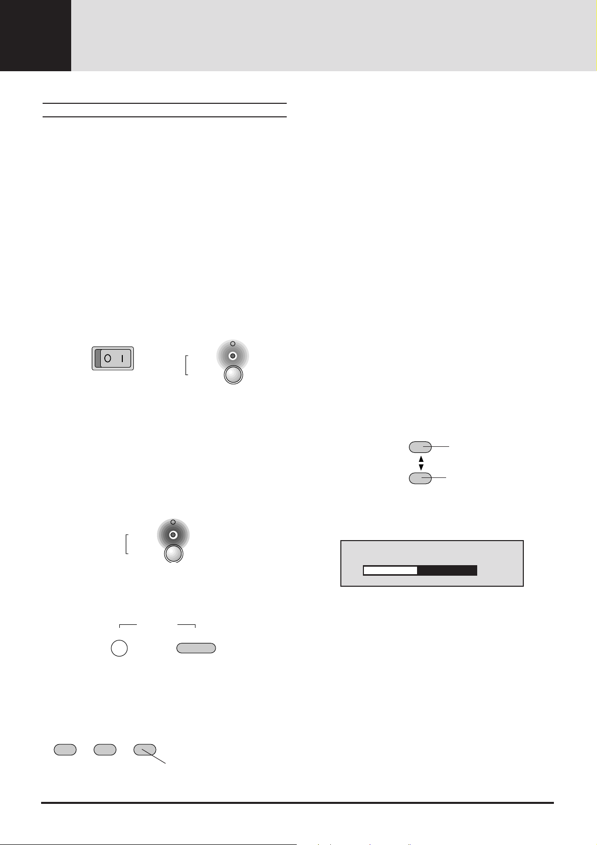
OPERATION4
General Controls
Getting started
This section describes the basic operation of the projector.
The operation may differ depending on the makeup of the
projector system; therefore, please follow the directions of
your system administrator.
Operation using the remote control is described here. The
following controls have the same function: the MENU button
of the main unit and that of the remote control, the SELECT
button of the main unit and the cursor button of the remote
control, the ENTER button of the main unit and the ENTER
button of the remote control.
1. Switch On the Main Power
Press the "1" side of the POWER switch located on the front
of the main unit.
The POWER indicator will light up orange and the unit will
be set to the standby mode.
STATUS
(OFF) (ON)
POWER
ON / OFF
<Select the input from the user memory>
Directly specify and call the list of user memories in which
the input signals and screen adjustment conditions have already been registered.
This function is valid when the on-screen menu is not displayed.
• Calling (Loading) Memory Lists "00 to 09"
Hold down the CTL button and press the number keys
that correspond with the numbers.
(Remote control number buttons 0 through 9 correspond
with memory lists 00 through 09.)
• Calling (Loading) Memory Lists "00 to 99"
Use the number buttons to enter the numbers that correspond with the memory lists, then press the LOAD
button.
When an entry mistake has been made, press the
CLEAR button.
* See "Data Reading of Registration Signals (Load)" on Page
E-60 when loading signal data while viewing the contents
from the on-screen menu display as well as when loading the
switcher signal data.
When the ST ATUS indicator is lit or flashing, see Page E-77.
2. Switch On the Power
<Main unit operation>
Press the POWER (ON/OFF) button.
The lit POWER indicator will change to green and the power
will be switched on.
STATUS
POWER
ON / OFF
<Remote control operation>
Press the POWER ON button.
POWER
OFF
ON
3. Select the Input
<Select from among the input selection b uttons>
Select the desired input connector.
4. Adjusting the Volume of the Built-in Speaker
VOLUME
The volume increases.
The volume decreases.
A press of the button will display the volume display for a
while.
Volume
–
The volume adjustment range is from 0 to 63.
+ 32
* To set the volume display so that it does not appear, see
"Selecting the On-screen Display ON/OFF" on Page E-37.
* When the unit is connected with a switcher and [Audio
Control] is set to [On], the volume button of the projector will
control the volume of the equipment that is connected to
AUDIO OUT of the switcher.
RGB1 RGB2
VIDEO/S-VIDEO
Each press toggles between SVIDEO and VIDEO .
E-34
Page 35
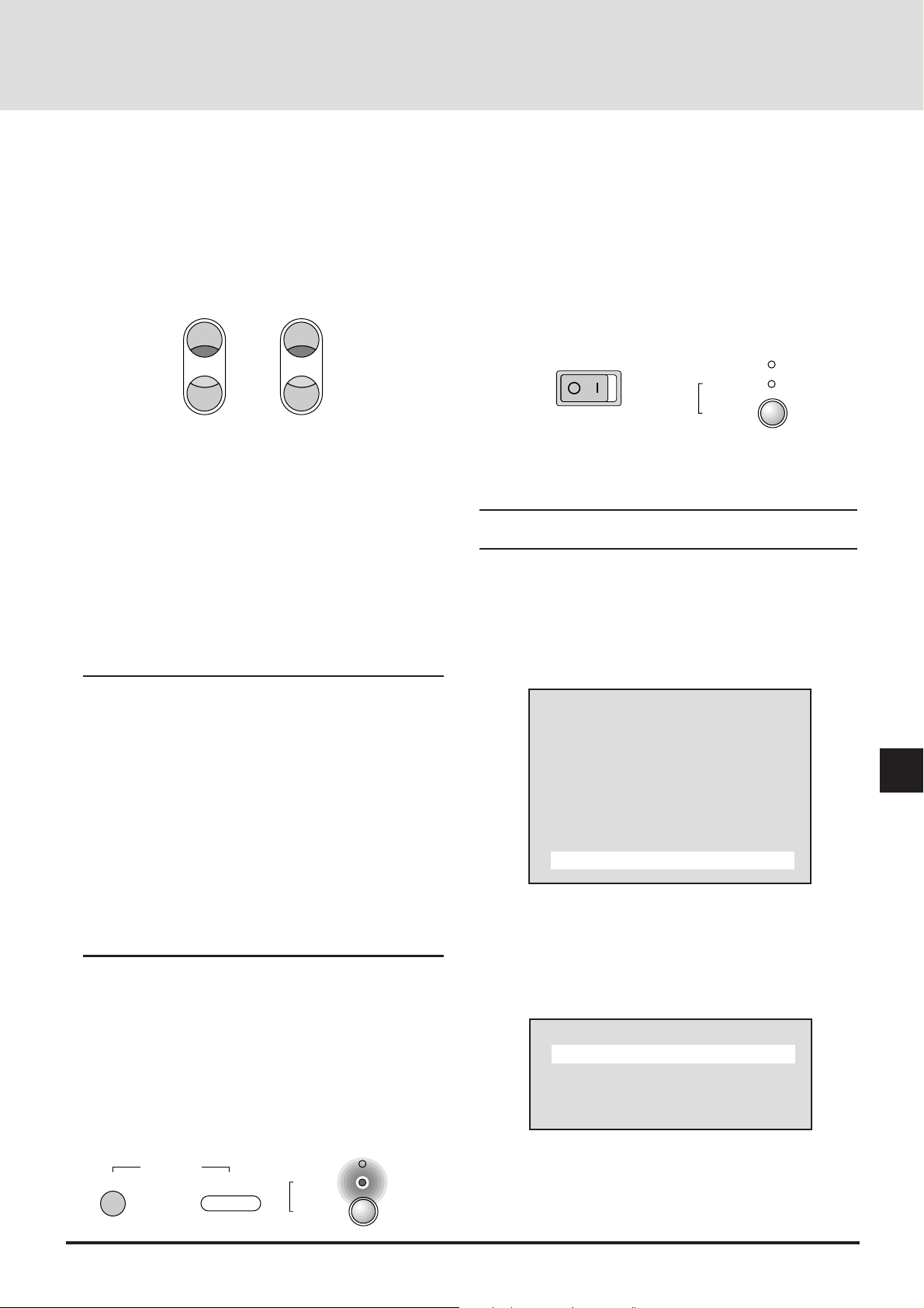
5. Adjust the Screen Size and then Adjust the Focus
When the projector is set up permanently, there is no need to
make the usual adjustments.
(The Zoom and Focus buttons do not function on GT2000R.)
A)Press the ZOOM W/T button and adjust the screen size.
B)Press the FOCUS +/- button and adjust the focus.
FOCUS ZOOM
+
-
W
T
<Main unit operation>
B) Press the POWER button for at least 2 seconds. The
"Power Of f" message will be displayed.
* The cooling fan will continue to turn for about 1 minute
after the power has been switched off. During this period, it
will not be possible to switch on the power again.
8. Switch Off the Main Power
Press the "0" side of the POWER switch located on the front
of the main unit.
STATUS
(OFF) (ON)
POWER
ON / OFF
6. Adjust the Screen and Picture (Only When Required)
When the screen is not displayed properly, adjust the screen.
When the tint of the picture or some other attribute is not
correct, adjust the picture. See "Adjusting the Screen" on
Page E-49 and "Adjusting the Picture" on Page E-44.
* When the input signal is selected with the user memory or
the channel memory and the auto memory save function is
set to [On], the adjustment data is overwritten.
See "Storing the Adjustment Data" on Page E-59 for
information about registering the input signal and adjustment data that are currently being projected.
NOTE: Selecting the Slot Directly When the ISS-6020 Is
Connected
When the ISS-6020 switcher is connected, the slot (channel)
of the switcher can be directly specified. (Valid when the onscreen menu is not displayed)
When one switcher is connected
Enter the channel number with the number button of the
remote contr ol, then press the ENTER button.
When two or more switchers are connected
Enter the two-digit channel number with the number buttons
of the remote contr ol, then press the ENTER button.
See "Selecting the Various Items and Switchers" on Page E58 for information about master switcher and slave switcher
number specification.
7. Switch Off the Power
<Remote control operation>
A) Press the POWER OFF button.
The STATUS indicator will flash in green for 1 minute
(and will be displayed while the cooling fan is turning).
The color of the POWER indicator will change to orange
(indicating the standby mode).
Also switch off the power to the equipment that is connected
to the projector.
Note: Do not switch off the main power before the fan has
stopped. It will cause damage.
On-screen Input Selection
Input selection is also permitted with the on-screen menu.
1. Press the MENU button to display the main menu.
Main Menu
Picture
Alignment
Memory
Switcher
Display Menu
Settings Menu
Source
2. Select [Source] of the main menu and press the ENTER
button. The source selection display will appear.
3. Press the cursor ▲/▼ button and select the target input
connector (source), then press the ENTER button to set.
Source
RGB1
RGB2
Video
S-Video
OFF
POWER
ON
STATUS
POWER
ON / OFF
E-35
Page 36
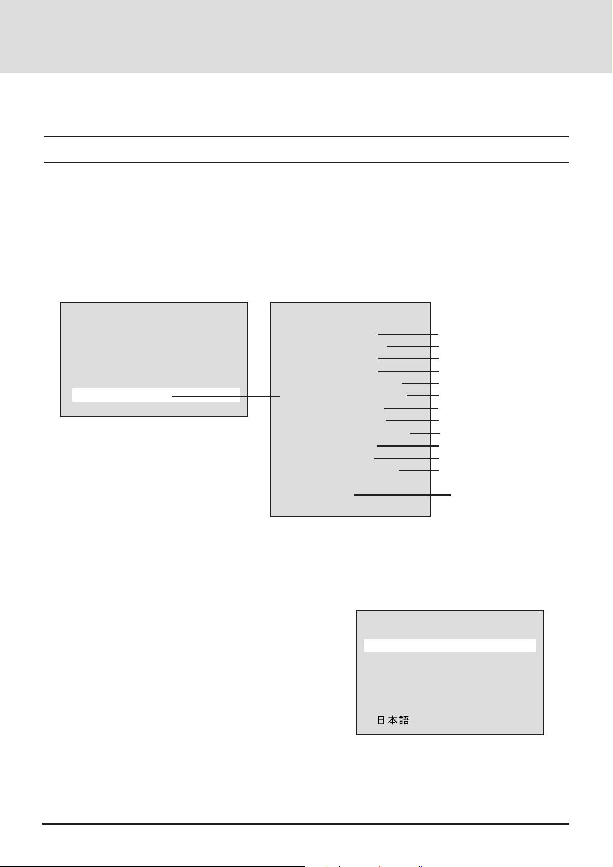
SETUP (Various Settings)
Please make settings in conjunction with both the projector and the system.
NOTE: To accommodate worldwide use of the projector, the default language setting for the projector is English. See below for the
detailed setting procedure. Descriptions given here assume that the languag e setting of the unit has already been set to English.
Default Settings of the Settings Menu
The unit is set as described below before it is shipped from the factory.
Please set any required items.
Press the MENU button to display [Main Menu], then select [Settings Menu] with the cursor button and press the ENTER button
to display the various settings.
Setting at Time of
Main Menu
Settings Menu
Factory Shipping
Picture
Alignment
Memory
Switcher
Display Menu
Settings Menu
Source
To turn off the on-screen menu display, press the
MENU button.
The display will return to the main menu. Press the
MENU button again to turn off the on-screen
menu.
Selecting the On-screen Language
[Language]
This is the language selection for the display characters of
the on-screen menu and other displays.
1. Select [Settings Menu] → [Language] from the main menu.
2. Press the cursor ▲/▼ button and select the language, then
press the ENTER button to set.
Language
Background
Auto Start
Auto Save
Onscreen Mute
Switcher Control
Ext. Control
Projector ID
Sync Termination
Projection
Ke ystone
Keystone Save
English
Language
English
Blue back
Off
Off
Off
Standalone
Off
00
Hi-impedance
Front Floor
00
Off
Currently selected
item
English
Deutsch
Français
Italianno
Espanol
Svenska
E-36
Page 37

Selecting the Background Color When There Is
No Signal [Background]
This is the setting of the background color when there is no input
signal.
1. Select [Settings Menu] → [Background] from the main menu.
2. Press the cursor ▲/▼ b utton and select the background color , then
press the ENTER button to set.
Blue...The background color will be blue.
Black...The background color will be b lack.
Selecting Auto Start [Auto Start]
When the main power switch is set to ON, this function switches
on the power without the need to press the power button.
1. Select [Settings Menu] → [Auto Start] from the main menu.
2. Press the cursor ▲/▼ button and select On/Off, then press the
ENTER button to set.
On .... The projector will start up when the main power is
switched on.
Off .... The projector will enter the standby mode when the
main power is switched on.
Background
Blue
Black
Auto Start
On
Off
Selecting the Automatic Memory Save Function
[Auto Save]
This function automatically saves the adjustment conditions to the
memory in use when screen adjustments or picture adjustments are
performed while projecting the image of the input equipment using
user memory or channel memory.
The auto save function saves the inf ormation when the MENU and
ENTER buttons are used upon exiting from the various adjustment
menus.
1. Select [Settings Menu] → [Auto Save] from the main menu.
2. Press the cursor ▲/▼ button and select On/Off, then press the
ENTER button to set.
On .... Auto memory saves are enabled.
Off .... Auto memory saves are disabled.
Selecting the On-screen Display ON/OFF
[On-screen Mute]
This is a selection of whether or not to show displays other than onscreen menu displays (such as simple condition displays, the adjustment bar which is displayed when the remote control VOLUME button is used to make an adjustment, and when switching
the input signal).
1. Select [Settings Menu] → [On-screen Mute] from the main menu.
2. Press the cursor ▲/▼ button and select On/Off, then press the
ENTER button to set.
On .... Displa ys will be muted.
Off .... Displa ys will not be muted.
Auto Save
On
Off
Onscreen Mute
On
Off
E-37
Page 38
Selecting the Switcher Control Method [Switcher
Control]
The switcher is a unit that switches the input equipment when a
number of different video devices or computers are connected.
When the REMOTE 1 connector is used, input selection and
adjustment are permitted by the projector. See "Using User
Memory and Channel Memory" on Page E-56.
See "(Connections with the ISS-6020)" on Page E-28 for information about connections.
1. Select [Settings Menu] → [Switcher Control] from the main menu.
2. Press the cursor ▲/▼ button and select the switcher connection
condition, then press the ENTER button to set.
Settings will become effective the next time the power is switched
on.
Standalone .......The projector used in stand alone opera-
tion.
SW 1 Leve l .......The projector used with one Switcher.
SW 2 Leve l .......The projector used with two or more
Switchers.
Selecting External Control Connections Settings
[Ext. Contr ol]
When using the EXT-CTL connector of the projector, set the
external control setting to [On].
1. Select [Settings Menu] → [Ext. Control] from the main menu.
2. Press the cursor ▲/▼ button and select On/Off, then press the
ENTER button to set.
On .... Enab les the EXT-CTL connector.
Off .... Disables the EXT-CTL connector.
Switcher Control
Standalone
SW 1 Level
SW 2 Level
The term switcher refers to the NEC ISS-6020 Switcher.
Ext. Control
On
Off
Setting the Projector ID Number [Projector ID]
Set identification numbers to the projectors when operating a
number of projectors (GT2000/GT2000R) by remote control or
when controlling a number of projectors by personal computer.
1. Select [Settings Menu] → [Projector ID] from the main menu.
2. Enter the ID number with the number buttons, then press the
ENTER button to set.
[00] will be set when using one projector .
When using a number of projectors, set [01] to [64].
• To delete the entry, press the CLEAR button of the remote control.
The setting will return to [00].
When operating a number of projectors by remote control, also set
the address of the remote control. See "Setting of the Remote
Control Address" on P age E-43.
Setting the ID of the projector to [00] permits remote control
operation irrespective of the ID of the remote control.
Projector ID
No.0 - 64
E-38
Page 39

Sync Signal Termination Setting
[Sync Termination]
This sets the impedance of the RGB/YCbCr Input 1 connector.
This function sets whether or not the unit will accommodate a 75
ohm output (specification) impedance of the video or personal
computer equipment.
1. Select [Settings Menu] → [Sync Termination] from the main
menu.
2. Press the cursor ▲/▼ button and select the termination resistance
value, then press the ENTER button to set.
75 ohms........................... When the impedance of the out-
put connector of the connected
equipment is 75 ohm.
High Impedance (Hi-Z)..... When the impedance of the out-
put connector of the connected
equipment is not 75 ohm.
To turn off the on-screen menu display, press the MENU button.
The display will return to the main menu. Press the MENU button
again to turn off the on-screen menu.
Selecting the Projector’ s Pr ojection Method [Pr ojection]
This selection of the projection method is made to suit the usage
conditions.
Model GT2000 is designed for front projection and model
GT2000R is designed for rear projection.
1. Select [Settings Menu] → [Projection] from the main menu.
2. Press the cursor ▲/▼ button and select the target projection, then
press the ENTER button to set.
Front floor ..............When the projector is placed on a table
and projects from the front
Rear ceiling............When the projector is suspended from
the ceiling and projects from the rear
Rear floor............... When the projector is placed on a table
and projects from the rear
Front ceiling ........... When the projector is suspended from
the ceiling and projects from the front
Sync T ermination
75Ω
Hi-Z
Projection
Front Floor
Rear Ceiling
Rear Floor
Front Ceiling
E-39
Page 40
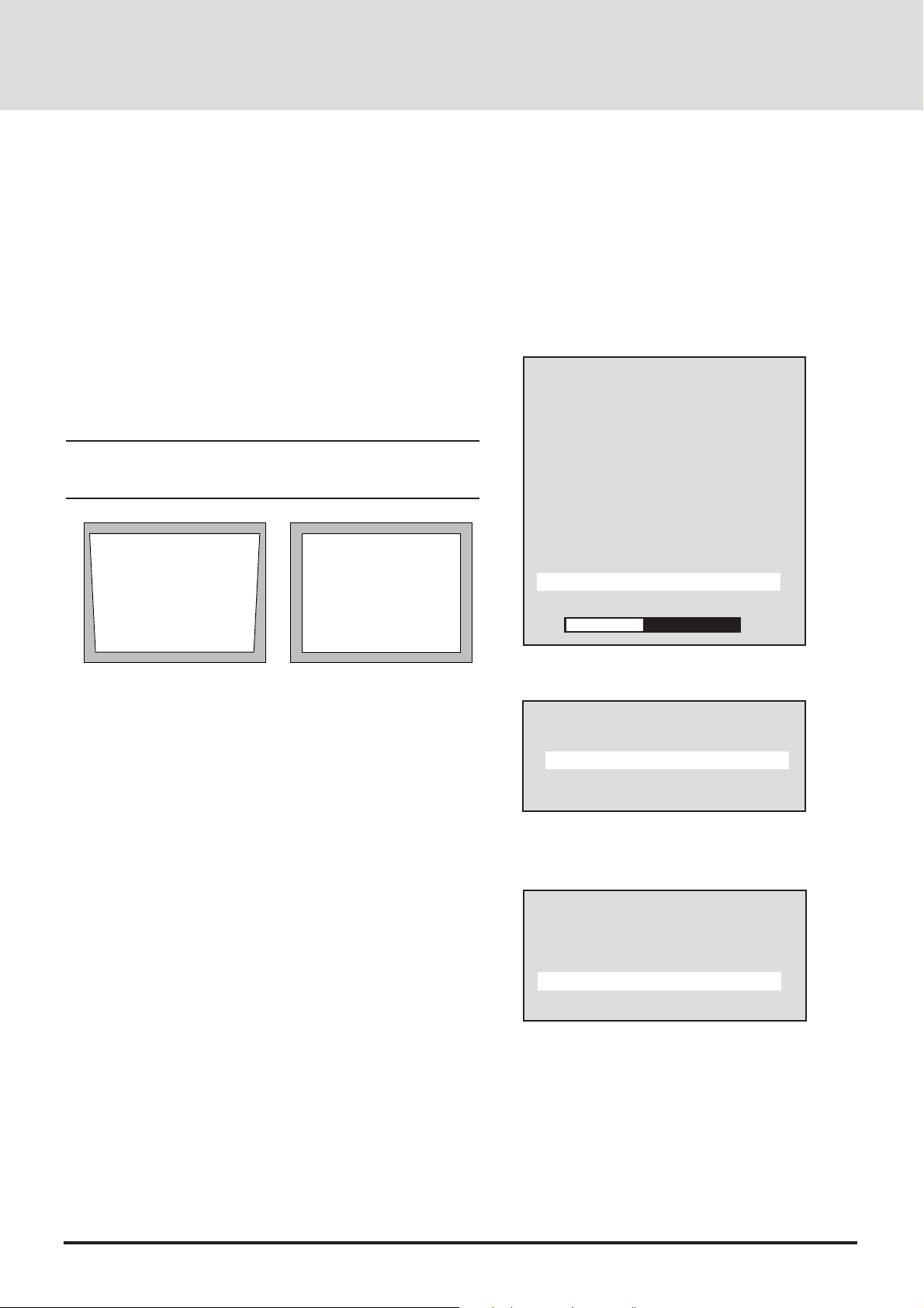
Selecting Correction and Storage of Keystone
Distortion [Keystone]
Keystone distortion arises when the angles are off between the
projector and screen in the vertical orientation at the time of setting
up the projector. The keystone function is used in this distortion
adjustment.
When the setting is permanent, setting the keystone save function
to On will enable projection using this adjustment value from the
next occasion.
• Adjusting Keystone Adjustment [Keystone]
1. Select [Settings Menu] → [Keystone] from the main menu.
The adjustment bar will be displayed.
2. Press the cursor § (–) / © (+) button and adjust so that the left and
right sides are parallel.
NOTE: This function will not work when the input signal is not
present. If this is the case, apply an signal and make the adjusment on
it.
[Keystone distortion] [No distortion]
Settings Menu
Language
Background
Auto Start
Auto Save
Onscreen Mute
Swithcer Control
Ext. Control
Projector ID
Sync T ermination
Projection
Keystone
Keystone Save
–
+ –10
• Setting Keystone Save [Keystone Save]
1. Select [Settings Menu] → [Keystone Save] from the main menu.
2. Press the cursor ▲/▼ button and select On/Off, then press the
ENTER button to set.
On .... Enables the keystone correction value at starting
time.
Off .... Sets the keystone correction value to the default
value at starting time.
To return to the default value, press the NORMAL button of the
remote control.
Press the cursor ▲/▼ button and select [Yes], then press the
ENTER button to return to the default value.
Keystone Save
On
Off
Normalize?
Keystone
Yes
No
E-40
Page 41
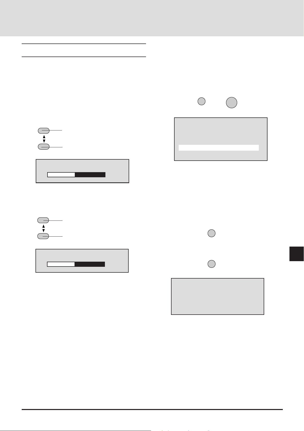
DISPLAY
Adjustments and Settings with the Remote Control
Buttons (Direct Operation)
Functions can be called directly using the remote control
buttons to make adjustments and settings (without the use of
the on-screen menu display).
• Returning to Standard Adjustments
Contrast and brightness will return to the standard settings.
This function is valid when the on-screen menu is not dis-
played.
Press the NORMAL button. The verification display will
appear. Press the ENTER button to set.
Adjustment of the Picture
Adjustments can be made for the separate input sources
(VIDEO, S-VIDEO, RGB1, and RGB2).
• Adjusting the contrast of the picture (Contrast)
CONTRAST
The picture will become denser. (+ direction)
The picture will become fainter. (- direction)
Contrast
–
The adjustment range is from -31 to +32.
•
Adjusting the brightness of the picture (Brightness)
BRIGHT
The picture will become lighter. (+ direction)
The picture will become darker. (- direction)
+ ±0
NORMAL
ENTER
Normalize?
Picture
Yes
No
To cancel, press the cursor ▼ button, select [No], and press
the ENTER button.
Display of Selected Input Information
This displays the currently selected input information.
Press the DISPLAY button to show this information.
The information remains for 10 seconds.
Brightness
–
The adjustment range is from -31 to +32.
+ ±0
The picture adjustment data can be stored (i.e., saved) to that
memory. See "Using User Memory and Channel Memory"
on Page E-56.
Press the CLEAR button to delete this display.
SETUP
RGB1
VGA
Source Lock :Off
Expand:On
Keystone :On
E-41
Page 42

ZOOM
MAGNIFY/REDUCE
W
T
+
-
Temporarily Turning Off the On-screen Men u
Display
This function is used to temporarily turn off the on-screen
menu display.
This will be conveniently used when making fine picture or
screen adjustments while viewing the whole screen.
Hold down the CTL button and press the DISPLAY button.
DISPLAY
CTL
This function will also be cancelled by pressing a button
other than the cursor ▲ / ▼ button, but the operation of the
button that is pressed will take effect.
Using Digital Zoom Function
The LCD panel of the projector has 136621024 pixels.
The digital zoom function converts input signals with resolu-
tions of less than 136621024 pixels to a number of pixels
that is close to 136621024 to provide an enlarged display.
Using Digital Enlargement
This function can provide an enlarged display of up to 8
times the size of a target portion. Hold down the CTL button
and press the ZOOM button. To move the selected portion,
use the cursor buttons.
Each press enlarges the pic-
CTL
ture.
Each press reduces the picture (toward the original size)
i
m)
6
5
4
3
2
1
0
1
0
12345678910111213
i
m)
A press of the EXPAND button results in a display that
corresponds to the resolution of the input signal.
A further press returns the display to the original condition.
EXPAND
i
m)
6
5
4
3
2
1
0
1
0
12345678910111213
Digital Zoom OFF
i
m)
6
5
4
3
2
1
0
1
0
12345678910111213
Digital Zoom ON
i
m)
i
m)
The cursor buttons are used to move the screen position.
i
m)
6
5
NOTE: When the Digital Zoom function is set to ON, the picture
quality may deteriorate depending on the signal. The default
setting of Digital Zoom is ON. When the Digital Zoom function
is switched OFF, the Horizontal/Vertical amplitude and the
Ke ystone adjustment ar e not a vailable .
4
3
E-42
Page 43

Adjusting Keystone Distortion
Keystone distortion arises when the angles are off between
the projector and screen in the vertical orientation.
The keystone function is used in this distortion adjustment.
Hold the CTL button down and use the KEYSTONE +/-
buttons to adjust the left and right sides so that they become
parallel.
Returning the RGB Input Signal to the Standard Adjustment
This function is used when something has gone wrong with
the screen at the time of RGB signal entry.
The function is valid when the on-screen menu is not being
displayed.
Press the SETUP button, then press the ENTER button.
FOCUS
+
CTL
[Keystone distortion]
-
KEYSTONE
[No distortion]
When the KEYSTONE item is set to [ON], this adjustment
condition will take effect when the power is switched on. See
"Selecting Keystone Distortion Correction and Storage" on
Page E-40.
Temporarily Turning Off the Picture and Audio
This function is used to temporarily turn off the picture or the
audio.
Picture .........A press of the PICTURE button will turn
off the picture. Another press will result in
the picture being projected.
Audio ...........A press of the AUDIO button will turn off
the audio. Another press will result in the
audio being output.
SETUP
Select an item from among the adjustment data stored to standard
memory that is close to the input signal.
When readjustment is necessary , adjust the screen or call up an item
that is close to the input signal from within the user memory.
Upon a return to the standard adjustment, the YCbCr input
setting becomes RGB input.
When a switcher is connected, the various items of the
switcher return to the default settings. (The sync termination
setting will be high impedance.)
ENTER
Memory Search
This function is valid when the on-screen menu is not being
displayed.
Press the SETUP button, then press the LOAD button.
If you've modified the settings in memory, use this function.
Remote Control Address Setting
When two or more projectors (GT2000/GT2000R) are used
with wireless remote control operation, identification (ID) is
given to the projectors and remote control so that other
projectors are not controlled erroneously. Projectors having
the same ID can be controlled.
A)Hold down the CTL button and press the Adr. button
(VOLUME ▼). The address display appears.
Address
RC Unit 01
MUTE
PICTURE
The background color of the screen will be black when the
picture is turned off.
AUDIO
B)Use the number buttons to enter a 2-digit ID that is the
same as the ID of the projector that is being controlled.
Addresses that can be specified are from 00 to 64.
Press the ENTER button to set.
When a mistake is made in the entry, press the CLEAR
button and start the entry again from Step A).
* The projector ID of the main unit can be checked with
[Settings Menu] → [Projector ID] of the main menu.
* Setting the ID of the remote control to 00 permits remote
control operation irrespective of the ID of the projector.
* If the batteries are removed from the remote control, the
remote ID will return to "00".
E-43
Page 44

ADJUSTING THE PICTURE AND THE AUDIO (Picture)
These functions adjust the picture and audio with the on-screen menu display.
When the input signal is selected with the user memory or the channel memory and the auto memory save function is set to [On],
the adjustment data is overwritten.
Default Picture Settings
Picture settings at the time of shipping from the factory are as described below.
Please set required items.
Press the MENU button to display [Main Menu], select [Picture] with the cursor button, then press the ENTER b utton to display
the picture.
Main Menu
Picture
Alignment
Memory
Switcher
Display Menu
Settings Menu
Source
Picture
Brightness
Contrast
Volume
Color
Tint
Sharpness
Image Mode
Settings at the Time of
Shipping from the Factory
Names of items that cannot
be adjusted with the currently selected input mode
are displayed in gray.
Normal
White Balance
Scan Mode
Interpolation
RGB/YCbCr
–
+ 0
Auto
PC Mode
RGB
Contents of the selected item
are displayed.
Adjusting the Picture (Brightness, Contrast, Color, Tint, and Sharpness)
Adjust these items to an optimum level in conjunction with the input image.
Select [Picture] from the main menu, then press the ENTER button.
When the item to be adjusted is selected, the adjustment bar of the selected item is displayed at the bottom edge of the display.
Change to the (–) direction Change to the (+) direction
+
-
The various adjustment ranges are from -31 to +32.
E-44
Picture
Brightness
Contrast
Volume
Color
Tint
Sharpness
Image Mode
White Balance
Scan Mode
Interpolation
RGB/YCbCr
–
+ -10
Page 45

Item § (–) Button © (+) Button Notes
Brightness Becomes darker Becomes lighter ––––
Contrast Picture becomes fainter Picture becomes denser ––––
Color Color becomes paler Color becomes deeper RGB input does not
apply
Tint Becomes more reddish Becomes more greenish RGB, PAL and
SECAM input do not
apply
Sharpness Picture becomes softer Picture becomes more distinct RGB input does not
apply
Adjusting the White Balance (White Balance)
This function corrects the black and white level of the input signal
and adjusts the color reproducibility.
Select [Picture] --> [White Balance] from the main menu.
Change to the (–) direction Change to the (+) direction
The various adjustment ranges are from -31 to +32.
+
-
White Balance
Brightness R
Brightness G
Brightness B
Contrast R
Contrast G
Contrast B
–
+ –10
Item Contents
Brightness R
Brightness G Adjustment of the black level of the picture
Brightness B
Contrast R
Contrast G Adjustment of the white level of the picture
Contrast B
Adjusting the Volume (Volume)
Select [Picture]→[Volume] from the main menu.
When the item to be adjusted is selected, the adjustment bar
of the selected item is displayed at the bottom edge of the
display.
Adjust the volume with the cursor § (–)/ © (+) buttons.
The adjustment range is from 0 to 63.
Picture
Brightness
Contrast
Volume
Color
Tint
Sharpness
Image Mode
White Balance
Scan Mode
Interpolation
RGB/YCbCr
E-45
–
+ 32
Page 46

Returning the Picture Adjustments to the Standard Settings
This function returns the adjustments of the selected items (i.e.,
brightness, contrast, color, tint, sharpness, and white balance) to
the standard adjustments suited to the input mode.
Example: Returning the contrast to the standard setting.
Select [Picture]→[Contrast] from the main menu.
Press the NORMAL button. The verification display will appear.
Press the ENTER button to set.
NORMAL
ENTER
Picture
Brightness
Contrast
Volume
Color
Tint
Sharpness
Image Mode
White Balance
Scan Mode
Interpolation
RGB/YCbCr
–
+ 0
T o cancel, press the cursor ▲ / ▼ button, select [No], then press the
ENTER button.
Selecting the Image Mode (Image Mode)
These are the picture adjustment modes available with the projector. Select the mode that is suited to personal computer text, or the
projected image of a video, etc.
Select [Picture]→[Image Mode] from the main menu.
Select the image mode with the cursor ▲/▼ button. Press the
ENTER button at the desired image mode.
Normal.........This is set for RGB input.
Natural 1
Natural 2 This is set for natural pictures.
Natural 3
DOC CAM ... This is set for the use of a monitor camera
when the screen is dark.
Normalize?
Contrast
Yes
No
Image Mode
Normal
Natural 1
Natural 2
Natural 3
Doc Cam
E-46
Page 47

Selecting the Scan Mode (Scan Mode)
This function selects whether there is a skip to every other scanning line, or whether scanning lines are reproduced in order and
projected.
Select [Picture]→[Scan Mode] from the main menu.
Select the scan mode with the cursor ▲/▼ button, then press the
ENTER button.
Auto ......................Automatic switching to suit the image.
Non Interlaced ......Scanning lines are scanned in order to
reproduce the image.
Suited for still pictures.
Interlaced Video
Interlaced PC ........Every other scanning line of the picture of
.....Every other scanning line in skipped to
reproduce the image.
Suited for moving pictures.
the personal computer input is skipped to
reproduce the image.
Selecting Smoothing (Interpolation)
Select the item that suits the projected image of the personal
computer or video signal, etc.
Scan Mode
Auto
Non Interlace
Interlace Video
Interlace PC
Select [Picture]→[Interpolation] from the main menu.
Select PC Mode or Video Mode with the cursor ▲/▼ button, then
press the ENTER button.
PC Mode ..............Set this mode when importance is placed
upon high-definition images such as with
workstations.
Video Mode ..........Set this mode when impor tance is placed
upon natural pictures such as with video
images.
NOTE: W hen a per sonal computer is selected and the Video Mode is
set, the picture may be disturbed depending on the signal. Should this
happen, please use the PC Mode.
Interpolation
PC Mode
Video Mode
E-47
Page 48
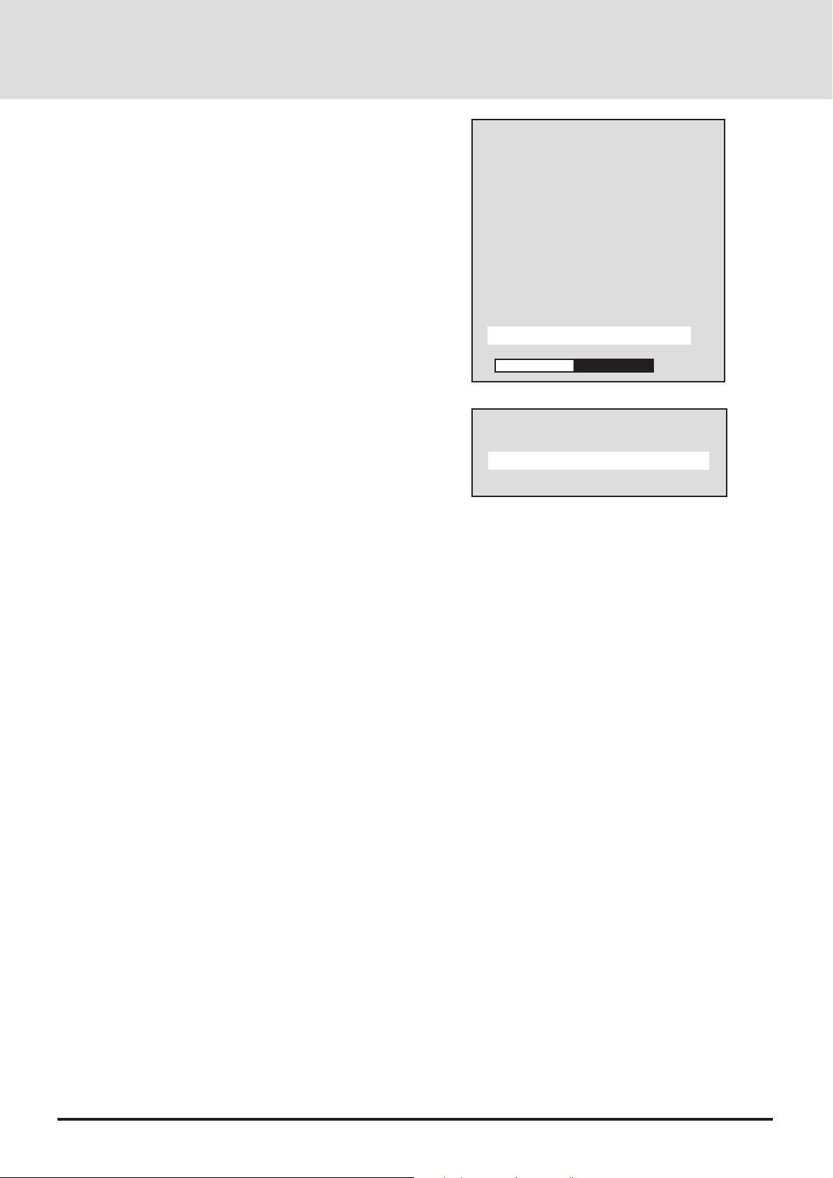
Selecting RGB/YCbCr (RGB/YCbCr)
This function sets the RGB 1/2 and YCbCr 1 input modes of the
RGB input 1/2 connector.
These settings are selected when there is input of a color-difference signal from a DVD player, etc.
Select [Picture]→[RGB/YCbCr] from the main menu and press
the ENTER button.
Select RGB/YCbCr with the cursor ▲/▼ button.
RGB .....................RGB input mode (when projecting from
personal computers and work stations)
YCbCr................... YCbCr input mode (when projecting from
DVD players)
Picture
Brightness
Contrast
Volume
Color
Tint
Sharpness
Image Mode
White Balance
Scan Mode
Interpolation
RGB/YCbCr
–
+ 32
When the RGB input is returned to the standard adjustment with
the SETUP and ENTER buttons of the remote control, the RGB/
YCbCr setting will be RGB input.
Direct Selection
You can select RGB or YCbCr input directly with the remote
control.
To do, press and hold CTL, then press RGB1 (or RGB2).
A press of CTL and RGB 1 (or RGB 2) buttons toggles between
RGB and YCbCr.
Note that this setting is not saved even though the auto save
function is set to "ON".
RGB/YCbCr
RGB
YCbCr
E-48
Page 49
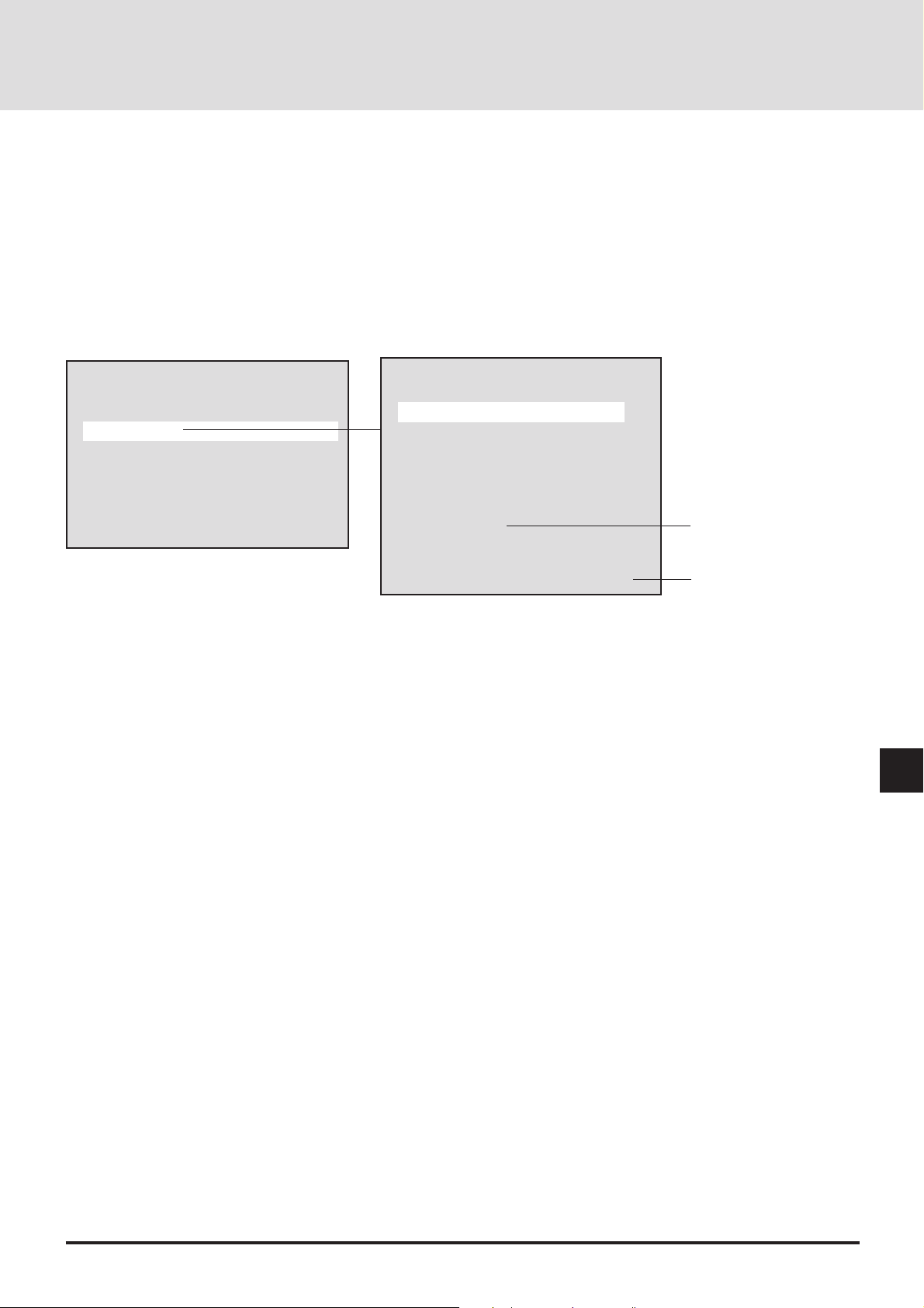
ADJUSTING THE SCREEN (Alignment)
When the input signal is selected with the user memory or the channel memory and the auto memory save function is set to [On],
the adjustment data is overwritten.
Default Screen Adjustment Settings
Settings at the time of shipping from the factory are as described below.
Please set required items.
Press the MENU button to display [Main Menu], select [Alignment] with the cursor button, then press the ENTER button to
display the alignment.
Main Menu
Picture
Alignment
Memory
Switcher
Display Menu
Settings Menu
Source
Alignment
H Position
V Position
Picture Adjust
Fine Picture
H Amplitude
V Amplitude
Image Filter
Settings at the Time of
Shipping from the Factory
OFF
Option
Auto Alignment
50
Adjustment values and setting conditions of the selected item are displayed.
Screen Adjustment Procedure
1. Input an RGB signal.
It will be projected as a standard signal.
2. Set Digital Zoom function to OFF.
Press the EXPAND button to set this to OFF. See Page E-42
3. Adjust the clock frequency and the horizontal phase. See Page E-51 and E-52.
4. Set Digital Zoom function to ON.
Press the EXPAND button to set this to ON.
5. Adjust the screen size and the display position.
When the screen size is not suitable, adjust it with the horizontal amplitude and the vertical amplitude. See Page E-53.
When the position is off, adjust the horizontal position and the vertical position. See Page E-50.
E-49
Page 50
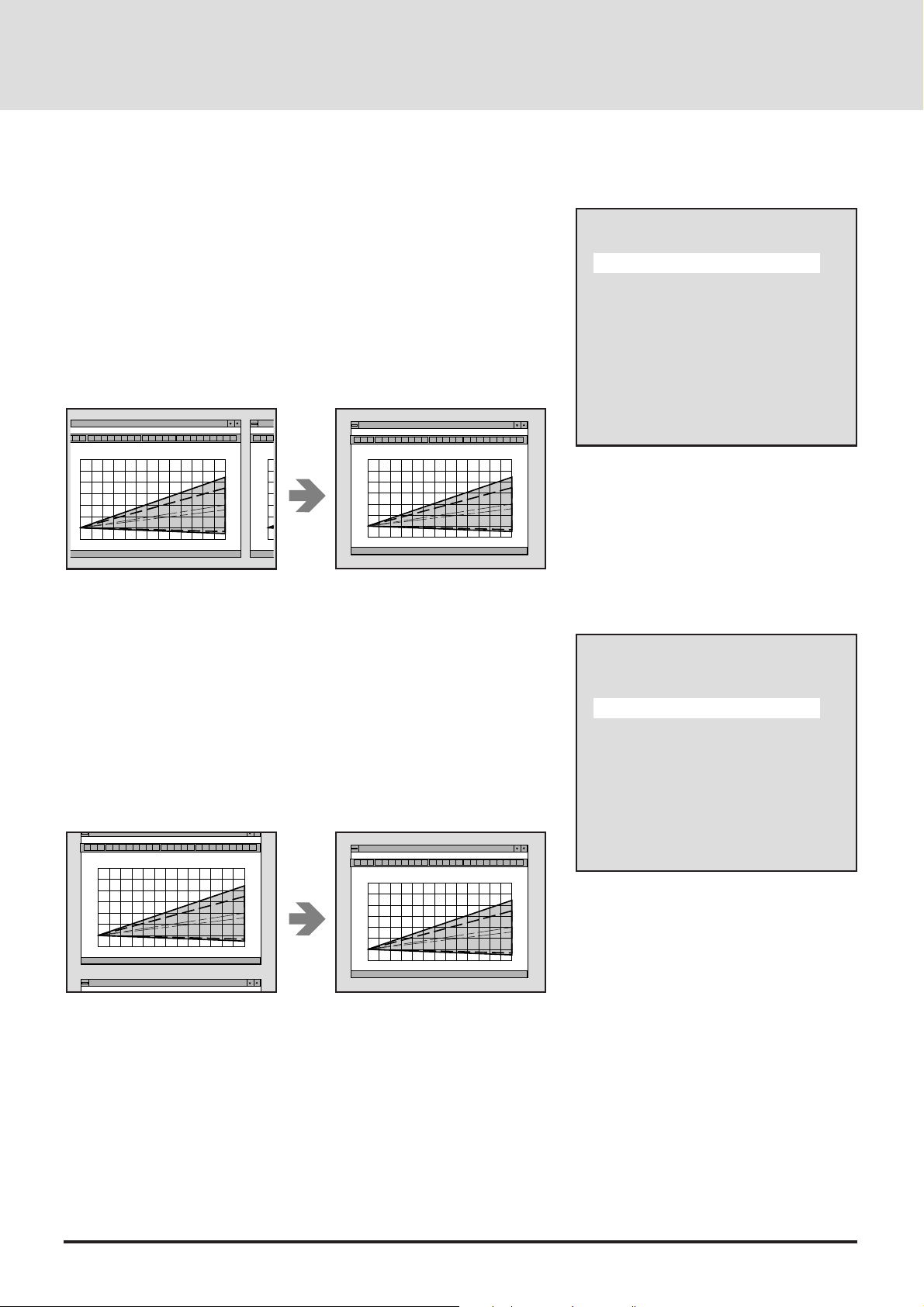
Adjusting the Screen Position (Horizontal Position and
Vertical P osition)
• Adjusting the Horizontal Position
Select [Alignment]→[H Position] from the main menu.
When the item to be adjusted is selected, the adjustment value of the selected
item is displayed at the bottom edge of the display.
Adjust the horizontal position with the cursor § (–)/ © (+) button.
The adjustment range will differ depending on the input signal.
Each press will move the horizontal position one pixel. Holding down the
button will move the horizontal position continuously.
i
i
m)
6
5
4
3
2
1
0
1
0
12345678910111213
m)
6
5
4
3
2
1
0
1
0
i
m)
i
m)
6
5
4
3
2
1
0
1
0
12345678910111213
i
m)
Alignment
H Position
V Position
Picture Adjust
Fine Picture
H Amplitude
V Amplitude
Image Filter
Option
Auto Alignment
50
• Adjusting the Vertical Position
Select [Alignment]→ [V Position] from the main menu.
When the item to be adjusted is selected, the adjustment value of the selected
item is displayed at the bottom edge of the display.
Adjust the vertical position with the cursor § (–)/ © (+) button.
The adjustment range will differ depending on the input signal.
Each press will move the vertical position one pix el. Holding down the b utton
will move the vertical position continuously.
i
m)
6
5
4
3
2
1
0
1
0
12345678910111213
i
m)
i
m)
6
5
4
3
2
1
0
1
0
12345678910111213
i
m)
Making Adjustments While Viewing the Entire Screen
Hold down the CTL button and press the DISPLAY button to temporarily
turn off the on-screen menu display. Now, only the cursor § (–)/ © (+)
button will function. When another button is pressed, the menu will come
back on.
Alignment
H Position
V Position
Picture Adjust
Fine Picture
H Amplitude
V Amplitude
Image Filter
Option
Auto Alignment
120
E-50
Page 51

Adjusting the Horizontal Pixel Size and Phase (Picture
Adjust and Fine Picture)
Before making the adjustment, press the EXPAND button and turn OFF the
Digital Zoom function.
Adjust the clock frequency, then adjust the horizontal position.
• Adjusting the Clock Frequency (Picture Adjust)
This function adjusts the pixel size of the computer and the pixel size of the
LCD of the projector so that they become the same size.
Select [Alignment]→ [Picture Adjust] from the main menu.
When the item to be adjusted is selected, the adjustment value of the selected
item is displayed at the bottom edge of the display.
Adjust the clock frequency with the cursor § (–) / © (+) button.
The optimum adjustment value is where the brightness of the screen becomes
constant (i.e., the bright and dark vertical bands disappear).
The adjustment range will differ depending on the input signal.
Holding down the button will change the clock frequency continuously. Fine
adjustments can be made by single presses of the button.
Alignment
H Position
V Position
Picture Adjust
Fine Picture
H Amplitude
V Amplitude
Image Filter
Option
Auto Alignment
1420
i
m)
6
5
4
3
2
1
0
1
0
12345678910111213
i
m)
E-51
Page 52
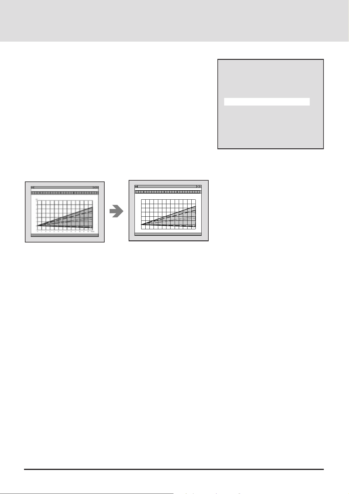
• Adjusting the Horizontal Phase (Fine Picture)
This function adjusts the phase of the pixels of the computer and the phase of
the pixels of the LCD of the projector so that they are the same phase. The
adjustment is made to the point at which the screen color infidelity and flicker
are at a minimum.
Select [Alignment] → [Fine Picture] from the main menu.
When the item to be adjusted is selected, the adjustment value of the selected
item is displayed at the bottom edge of the display.
Adjust the horizontal phase with the cursor § (–)/ © (+) button.
The optimum adjustment value is where the screen color infidelity and flicker
are at a minimum.
The adjustment range is from 0 to 255.
Holding down the button will change the horizontal phase continuously. Fine
adjustments can be made by single presses of the button.
i
m)
6
5
4
3
2
1
0
1
0
12345678910111213
i
m)
Alignment
H Position
V Position
Picture Adjust
Fine Picture
H Amplitude
V Amplitude
Image Filter
Option
Auto Alignment
183
Making Adjustments While Viewing the Entire Screen
Hold down the CTL button and press the DISPLAY button to temporarily turn
off the on-screen menu display . No w , only the cursor § (–) / © (+) button will
function. When another button is pressed, the menu will come back on.
Last press the EXPAND button and turn on the Digital Zoom function.
E-52
Page 53

Changing the Display Size (Horizontal Amplitude and V er tical Amplitude)
The projector already stores the standard personal computer and work station
resolutions in standard memory. When an RGB signal is input, the closest
resolution is selected from among those stored and the signal is displayed.
(When the information is stored in the user memory, it is searched from the
user memory.) It is for this reason that when the scanning frequency differs
from the value of the standard memory, the display area or aspect ratio will
also differ . The horizontal magnif ication and vertical magnifica tion are used to
adjust this.
• Adjusting the Horizontal Amplitude
This function adjusts the horizontal display size to suit the screen.
Select [Alignment] → [H Amplitude] from the main menu.
When the item to be adjusted is selected, the adjustment value of the selected
item is displayed at the bottom edge of the display.
Adjust the horizontal amplitude with the cursor § (–)/ © (+) button.
The adjustment range will differ depending on the input signal.
Holding down the button will result in a continuous change. Fine adjustments
can be made by single presses of the button.
i
i
m)
6
5
4
3
2
1
0
1
0
12345678910111213
i
m)
m)
6
5
4
3
2
1
0
1
0
12345678910111213
i
m)
Alignment
H Position
V Position
Picture Adjust
Fine Picture
H Amplitude
V Amplitude
Image Filter
Option
Auto Alignment
1368
• Adjusting the Vertical Amplitude
This function adjusts the vertical display size to suit the screen.
Select [Alignment] → [V Amplitude] from the main menu.
When the item to be adjusted is selected, the adjustment value of the selected
item is displayed at the bottom edge of the display.
Adjust the vertical amplitude with the cursor § (–)/ © (+) button.
The adjustment range will differ depending on the input signal.
Holding down the button will result in a continuous change. Fine adjustments
can be made by single presses of the button.
i
m)
i
m)
6
5
4
3
2
1
0
1
0
12345678910111213
i
m)
6
5
4
3
2
1
0
1
0
12345678910111213
i
m)
Change the horizontal or the vertical amplitude when the aspect ratio of the
screen differs from normal (i.e., a circle has become and ellipse).
Alignment
H Position
V Position
Picture Adjust
Fine Picture
H Amplitude
V Amplitude
Image Filter
Option
Auto Alignment
1024
E-53
Page 54
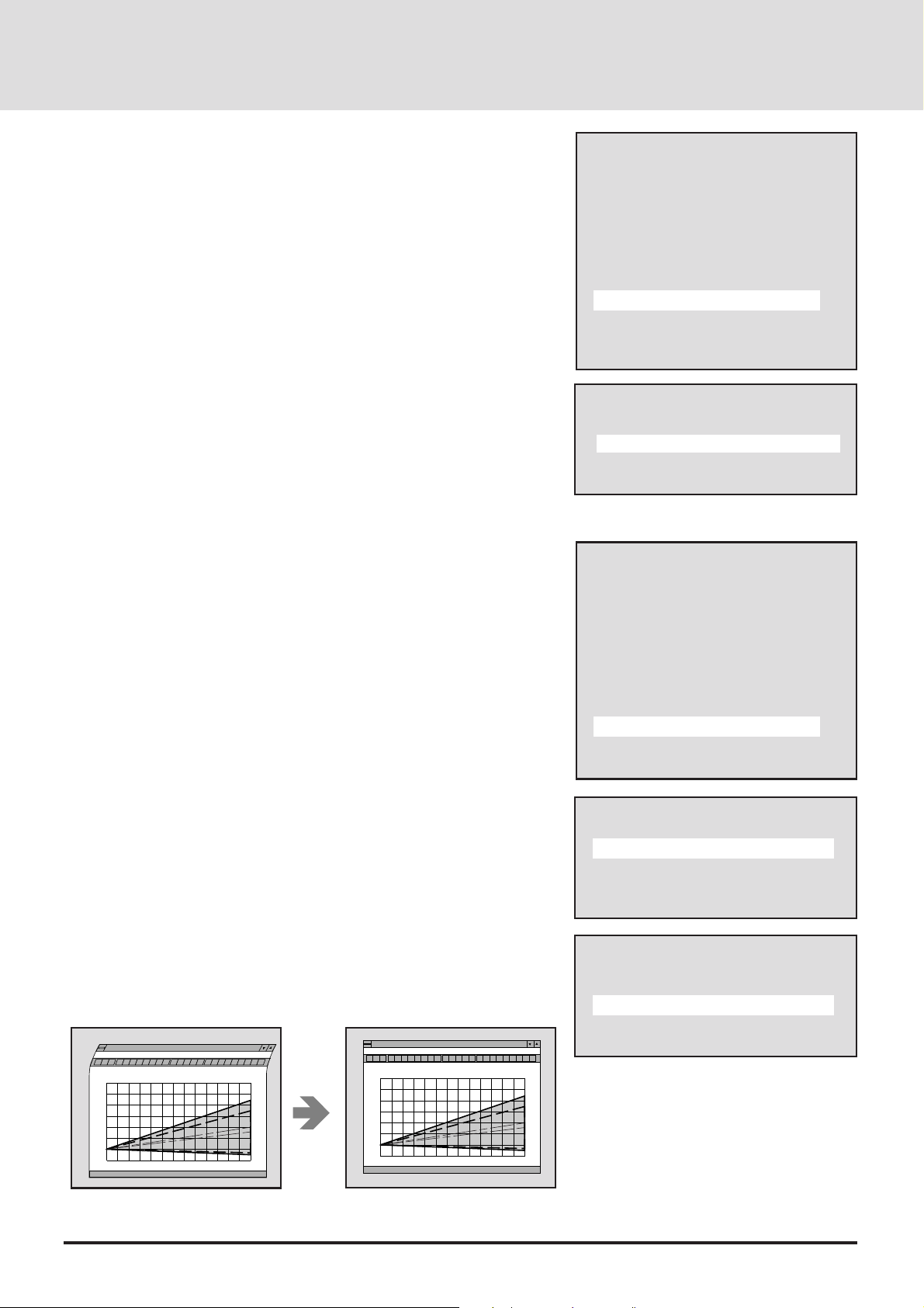
• Reducing Noise (Image Filter)
This function reduces video noise.
Select [Alignment] → [Image Filter] from the main menu, then press the
ENTER button. The image filter selection display will appear.
Select On/Off with the cursor ▲/▼ button.
On ........................The low-pass filter is applied.
Off ........................The filter is removed.
Screen adjustments are possible even when the filter is On.
Alignment
H Position
V Position
Picture Adjust
Fine Picture
H Amplitude
V Amplitude
Image Filter
Option
Auto Alignment
Filter
On
Off
Other Screen Adjustments (Vertical Phase, Skew Correction, Sync Position, and Clamp Timing)
Select [Alignment] → [Option] from the main menu, then press the ENTER
button. The option menu will be displayed.
• Vertical Phase
This function adjusts the vertical pixel phase when an irregularity arises while
making fine vertical movements of the screen or in the interlaced display.
Select [V Phase] with the cursor ▲/▼ button.
When the item to be adjusted is selected, the adjustment value of the selected
item is displayed at the bottom edge of the display.
Adjust to a normal condition with the cursor § (–)/ © (+) button.
The adjustment range is from 0 to 7.
• Skew Correction
This function adjusts the vertical bending of the screen.
Select [Skew Correction] with the cursor ▲/▼ button.
When the item to be adjusted is selected, the adjustment value of the selected
item is displayed at the bottom edge of the display.
Adjust the bending with the cursor § (–)/ © (+) button.
The adjustment range is from 0 to 8.
Alignment
H Position
V Position
Picture Adjust
Fine Picture
H Amplitude
V Amplitude
Image Filter
Option
Auto Alignment
Option
V Phase
Skew Correction
Sync Position
Clamp Timing
Option
V Phase
Skew Correction
Sync Position
Clamp Timing
i
m)
6
5
4
3
2
1
0
1
0
12345678910111213
i
m)
6
5
4
3
2
1
0
1
0
i
m)
12345678910111213
i
m)
E-54
Page 55
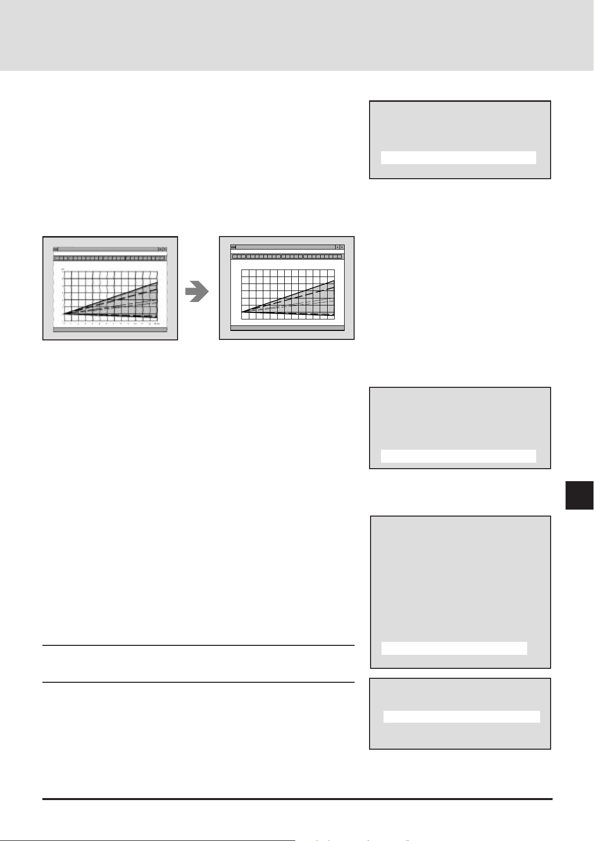
• Sync Position
This function selects whether the leading edge or the trailing edge of the
horizontal sync pulse is set to the standard position (i.e., the PLL phase basis
of comparison) and switches the sync position when jitter appears on the
screen.
Select [Sync Position] with the cursor ▲/▼ button.
When an item is selected, its adjustment values are indicated on the right
bottom of the menu.
While viewing the screen, select the item that results in the least distortion
with the cursor § (–)/ © (+) button.
The adjustment values are 0 or 1.
i
m)
6
5
4
3
2
1
0
1
0
12345678910111213
i
m)
• Clamp Timing
This function sets the standard position of the black level of the picture and is
used to set the level of screen brightness to an optimum level.
Select [Clamp Timing] with the cursor ▲/▼ button.
Selecting sync position moves the horizontal position. Adjust the horizontal
position.
While viewing the screen, select 0 or 1 with the cursor § (–)/ © (+) button.
Option
V Phase
Skew Correction
Sync Position
Clamp Timing
Option
V Phase
Skew Correction
Sync Position
Clamp Timing
Adjusting the Alignement Automatically (A uto Alignment)
This function automatically adjusts the clock frequency , the horizontal/vertical
position and H/V amplitude.
Depending on the pattern, adjustment may not be possible.
Select [Alignment] → [Auto Alignment] from the main menu, then press the
ENTER button. The verification display will appear.
Select Yes/No with the cursor ▲/▼ button.
Repeat until an optimum screen is obtained.
NOTE: Automatic adjustment will not function with VIDEO or S-VIDEO input.
When using RGB input, automatic adjustment will not function when NTSC, P AL/
SECAM, or HDTV is input.
Alignment
H Position
V Position
Picture Adjust
Fine Picture
H Amplitude
V Amplitude
Image Filter
Option
Auto Alignment
Auto Alignment
On
Off
E-55
Page 56

USING USER MEMORY AND
CHANNEL MEMORY (Memory)
Before Using the Memory Function
The projector uses a microprocessor to automatically identify the input signal. Therefore, it is necessary to set and store
in the microprocessor the adjustment conditions of such settings as the alignments and picture settings that match the
input signal and that an optimum picture can be reproduced.
The projector is equipped with five kinds of memory. There
is standard memory that cannot be overwritten, user memory
to which the user can freely write or overwrite (and to which
switcher channels can be registered), special switcher channel memory that is used when this main unit and a number of
switchers are connected and used together , the default area
in a one-to-one correspondence with areas of the standard
memory, and last memory that stores the latest settings for
each source (RGB1, RGB2, Video, and S-Video)
T ypes of Memory
• Standard Memory (Preset at Time of Shipping)
Video signals of the type used in personal computers and
work stations currently on the market hav e been registered in
the projector as standard data (and cannot be overwritten).
See "Displayable Video Signals" on Page E-82.
When displaying personal computer video signals (resolution/frequency) that have not been registered to standard
memory, make the screen and picture adjustments and then
register them to user memory.
• User Memory
When data that has been adjusted by the user is stored to user
memory, it can be called back and used at any time.
A maximum of 100 items of screen and/or picture adjustment
or setting data can be registered.
• Default Area
This is a rewritable memory that is in a one-to-one correspondence with areas of the standard memory.
The projector searches the settings in the default area before
the standard memory.
The factory shipped default area settings are the same as in
the standard memory.
• Last Memory
This is a memory that stores the last settings for each source
(RGB1, RGB2, Video, and S-Video).
Switching sources will store the settings in memory . For this
reason, even if the memory is not used, returning to its
original source will store the adjustments in memory.
Automatic Searc hes of Memory
The channel memory is searched first when used with the
switcher (s).
When the input is switched, the projector searches the user
memory for the existence of applicable registration memory
during input selection (of input source) or switcher slot selection (RGB and RGB2 only). When more than one such
memory item appear, the most recent memory number is
selected. When there is no such memory item, the unit
searches irrespective of input selection or slot selection.
When there is no applicable memory item in user memory,
the default area and a standard memory search is performed
in this order (but there will not be a search when there is a
skip setting).
• Channel Memory
This special memory for switchers is used to simultaneously
register the screen adjustment data and the data of the
switcher when the projector is used in conjunction with a
switcher.
A maximum of 100 channels (10 per switcher with max. of
10 switchers) of setting data (for the various pieces of equipment that are connected to the switchers) and the screen and
picture adjustment data (adjusted by the projector) can be
registered.
E-56
Page 57

Memory Selection and Item Contents
Selecting Memory Display
The user memory is displayed by pressing the MENU button and displaying [Main Menu], selecting [Memory] with the cursor
button, and then pressing the ENTER button.
To switch between user memory and channel memory displays, hold down the CTL button and select with the cursor ▲/▼
button.
Switch pages with the cursor § (–)/ © (+) button. (There are 10 pages of user memory and 10 pages of channel memory.)
To display the list number selection and the registration menu, use the cursor ▲/▼ button to align the selection bar with the
desired list number, then press the ENTER button.
Main Menu
Picture
Alignment
Memory
Switcher
Display Menu
Settings Menu
Source
User Memory
P01/10
No Name Source Slot Lock
00 CUTOM 0001 RGB1 Off
01
02
03 CUTOM 0004 S-VIDEO Off
04
05
06 CUTOM 0007 YCbCr1 On
07 CUTOM 0008 RGB2 On
08
09 CUTOM 0010 VIDEO Off
Channel Memory
P01/10
No Name Source Lock
00 CUTOM 0001 RGB1 Off
01
02
03 CUTOM 0004 S-VIDEO Off
04
05
06 CUTOM 0007 YCbCr1 On
07 CUTOM 0008 RGB2 On
08
09 CUTOM 0010 VIDEO Off
Signal Entry
Entry Copy
Entry Move
Entry Delete
Change Defalut
Memory edit
Load
Store
E-57
Page 58

Selecting the V arious Items and Switc hers
• Selecting User Memory
No.........................List number
Name....................Signal name entered by the user
Source ..................This is the set input mode.
(RGB 1, RGB 2, YCbCr1, YCbCr2, VIDEO, and S-VIDEO)
Slot .......................This is the slot number of the channel. It is termed the channel in this manual.
04 indicates the selection of the equipment that is connected to the number 04 slot of the switcher.
Currently selected page
User Memory
No Name Source Slot
Lock
00 CUTOM 0007 RGB1 04
*
On
01 CUTOM 0008 RGB2 07/08
The [*] display appears when the skip setting is on.
Off
02
07/08 indicates the selection of the equipment that is connected to the number 8 slot of
the master switcher, which is connected to the number 7 slot of the slave switcher.
P01/10
Total number of pages
Lock......................This is the on/off setting of the auto scan function at the time of input signal switching. It is selected
with the edit menu.
• Selecting Channel Memory
In user memory, the slot specification differs.
Currently selected page
Channel Memory
P01/10
No Name Source
Lock
00 CUTOM 0007 RGB1
On
01 CUTOM 0008 RGB2
Off
In channel memory , the memory number becomes the channel number , which corr esponds with the slot number of the switcher.
In signal registration, this number is selected and registration is made to this number.
Settings will differ depending on the switcher connection method. See "Changing the Slot Number of the Switcher (slot)
Switcher Control" on Page E-67.
When the Setting is [SW 1 Level] (One Unit)
When the Setting is [SW 1 Level] (One Unit)
Channel numbers 10 through 19 correspond with switcher slot numbers 01 through 10. (Note that channel 10 will be slot 10, and
channel 11 will be slot 01.)
When the Setting is [SW 2 Level] (Two or More Units)
Channel numbers 00 through 09 correspond with slot numbers 1 through 10 of the slave switcher that is connected to slot 10 of
the master switcher.
Channel numbers 10 through 19 correspond with slot numbers 1 through 10 of the slave switcher that is connected to slot 1 of the
master switcher.
Channel numbers 90 through 99 correspond with slot numbers 1 through 10 of the slave switcher that is connected to slot 9 of the
master switcher.
Total number of pages
E-58
Page 59

Storing the Adjustment Data (Store)
This function is used to store the screen and picture adjustment data currently
being projected.
The signal name and other data can be edited later.
1. Project the Picture of the Input Equipment
Select [Memory] → [User Memory] or [Channel Memory] from the main
menu.
The user memory or channel memory will be displayed.
See "Selecting Memory Display" on Page E-57 for details.
2. Select the Number to Be Stored
Press the remote control ▲/▼ button and select the list number or the channel
number, then press the ENTER button.
The display will change to the signal registration menu.
(When input selection and projection are conducted from the user memory or
the channel memory, the selection cursor will mo v e to that number.)
User Memory
P01/10
No Name Source Slot Lock
00 CUTOM 0001 RGB1 Off
01
02
03 CUTOM 0004 S-VIDEO Off
04
05
06 CUTOM 0007 YCbCr1 On
07 CUTOM 0008 RGB2 On
08
09 CUTOM 0010 VIDEO Off
User Memory
P01/10
No Name Source Slot Lock
00 CUTOM 0001 RGB1 Off
01
02
03 CUTOM 0004 S-VIDEO Off
04
05
06 CUTOM 0007 YCbCr1 On
07 CUTOM 0008 RGB2 On
08
09 CUTOM 0010 VIDEO Off
3. Storing the Adjustment Data
1) Press the remote control ▲/▼ button, select [Store], then press the ENTER
button.
The display will change to the store verification display.
2) Press the remote control ▲/▼ b utton, select Yes/No, then press the ENTER
button.
* When a registered number is selected, the overwrite verification display will
appear.
This ends the data storage procedure.
T o turn of f the display, press the MENU button. When the display has returned
to the main menu, press the MENU button again to turn off the display.
Signal Entry
Entry Copy
Entry Move
Entry Delete
Change Defalut
Memory edit
Load
Store
Store?
Yes
No
Overwrite?
Yes
No
E-59
Page 60

Data Reading of Registration Signals (Load)
Adjustment and setting data are registered to suit the purpose of the external
equipment in the user memory and channel memory. This allows the input to
be switched and projected immediately when the projector is used in a system
or some other configuration. The desired adjustment and setting data can also
be called without switching the input.
1. Displaying the Memory Display
Select [Memory] → [User Memory] or [Channel Memory] from the main
menu.
The user memory or channel memory will be displayed.
See "Selecting Memory Display" on Page E-57 for details.
User Memory
P01/10
No Name Source Slot Lock
00 CUTOM 0001 RGB1 Off
01
02
03 CUTOM 0004 S-VIDEO Off
04
05
06 CUTOM 0007 YCbCr1 On
07 CUTOM 0008 RGB2 On
08
09 CUTOM 0010 VIDEO Off
2. Select the Desired Number
Press the remote control ▲/▼ button and select the list number or the channel
number, then press the ENTER button.
The display will change to the signal registration menu.
3. Retrieving the Signal Data
Press the remote control ▲/▼ b utton and select [Load].
Retrieving All the Data
Press the ENTER button.
The display will change to the load verification display.
Press the remote control ▲/▼ button, select Yes/No, then press the ENTER
button.
Retrieving Data Other than Source Data
(Data is called without performing input switching.)
Hold down the CTL button and press the ENTER b utton.
The display will change to the data load verification display.
Press the remote control ▲/▼ button, select Yes/No, then press the ENTER
button.
This ends the data retrieving procedure.
At this time, auto search during input signal switching will be invalid. (Lock On
condition.)
User Memory
P01/10
No Name Source Slot Lock
00 CUTOM 0001 RGB1 Off
01
02
03 CUTOM 0004 S-VIDEO Off
04
05
06 CUTOM 0007 YCbCr1 On
07 CUTOM 0008 RGB2 On
08
09 CUTOM 0010 VIDEO Off
Signal Entry
Entry Copy
Entry Move
Entry Delete
Change Defalut
Memory edit
Load
Store
Load?
Yes
No
Data Load?
Yes
No
E-60
Page 61

Copying All the Data (Entry Copy)
This function copies the registered signal data (i.e., the copy source) to the
selected number (i.e., the copy destination).
1. Displaying the Signal Registration Menu Display
Select [Memory] → [User Memory] or [Channel Memory] from the main
menu, then press the ENTER button.
The signal registration menu display will appear .
See "Selecting Memory Display" on Page E-57 for details.
2. Copying
Press the remote control ▲/▼ button and select [Entry Copy], then press the
ENTER button.
The display will change to the user memory or the channel memory display .
"Copy: Copy Source Selection" will appear at the bottom of the display .
Signal Entry
Entry Copy
Entry Move
Entry Delete
Change Defalut
Memory edit
Load
Store
User Memory
P01/10
No Name Source Slot Lock
00 CUTOM 0001 RGB1 Off
01
02
03 CUTOM 0004 S-VIDEO Off
04
05
06 CUTOM 0007 YCbCr1 On
07 CUTOM 0008 RGB2 On
08
09 CUTOM 0010 VIDEO Off
Entry Copy: Select Source
1) Press the remote control ▲/▼ button and select the copy source number,
then press the ENTER button.
"Copy: Copy Destination Selection" will appear at the bottom of the display .
2) Press the remote control ▲/▼ button and select the copy destination number ,
then press the ENTER button.
When the signal data has already been registered to the copy destination, the
verification display will appear. Press the remote control ▲/▼ button and
select Yes/No, then press the ENTER button.
This ends the copy procedure.
To turn off the display, press the MENU button. The display will return to the
main menu. A further press of the MENU button will turn off the display.
User Memory
P01/10
No Name Source Slot Lock
00 CUTOM 0001 RGB1 Off
01
02
User Memory
P01/10
No Name Source Slot Lock
00 CUTOM 0001 RGB1 Off
01 CUTOM 0007 YCbCr1 On
02
Overwrite?
Yes
No
E-61
Page 62

Moving Data (Entry Move)
This function moves the registered signal data (i.e., the move source) to the
selected number (i.e., the move destination).
1. Displaying the Signal Registration Menu Display
Select [Memory] → [User Memory] or [Channel Memory] from the main
menu, then press the ENTER button.
The signal registration menu display will appear .
See "Selecting Memory Display" on Page E-57 for details.
2. Moving
Press the remote control ▲/▼ button and select [Entry Move], then press the
ENTER button.
The display will change to the user memory or the channel memory display.
"Move: Move Source Selection" will appear at the bottom of the display.
1) Press the remote control ▲/▼ button and select the move source number,
then press the ENTER button.
"Move: Move Destination Selection" will appear at the bottom of the
display.
2) Press the remote control ▲/▼ button and select the move destination
number, then press the ENTER button.
When the signal data has already been registered to the move destination, the
verification display will appear. Press the remote control ▲/▼ button and
select Yes/No, then press the ENTER button.
Signal Entry
Entry Copy
Entry Move
Entry Delete
Change Defalut
Memory edit
Load
Store
User Memory
P01/10
No Name Source Slot Lock
00 CUTOM 0001 RGB1 Off
01
02
03 CUTOM 0004 S-VIDEO Off
04
05
06 CUTOM 0007 YCbCr1 On
07 CUTOM 0008 RGB2 On
08
09 CUTOM 0010 VIDEO Off
Entry Move: Select Source
User Memory
P01/10
No Name Source Slot Lock
00 CUTOM 0001 RGB1 Off
01
02
This ends the move procedure.
To turn off the display, press the MENU button. The display will return to the
main menu. A further press of the MENU button will turn off the display.
User Memory
P01/10
No Name Source Slot Lock
00 CUTOM 0001 RGB1 Off
01 CUTOM 0007 YCbCr1 On
02
03 CUTOM 0004 S-VIDEO Off
04
05
06
07 CUTOM 0008 RGB2 On
08
09 CUTOM 0010 VIDEO Off
Overwrite?
Yes
No
E-62
Page 63

Deleting a Range of Data (Entry Delete)
This function specifies the range that is to be deleted and deletes the signal
data.
1. Displaying the Signal Registration Menu Display
Select [Memory] → [User Memory] or [Channel Memory] from the main
menu, then press the ENTER button.
The signal registration menu display will appear .
See "Selecting Memory Display" on Page E-57 for details.
2. Deleting
Press the remote control ▲/▼ button and select [Entry Delete], then press the
ENTER button.
The display will change to the user memory or the channel memory display .
"Delete: Starting No. Selection" will appear at the bottom of the display.
1) Press the remote control ▲/▼ button and select the starting number of the
deletion, then press the ENTER button.
"Delete: Ending No. Selection" will appear at the bottom of the display .
2) Press the remote control ▲/▼ button and select the ending number of the
deletion, then press the ENTER button.
When only one digit is to be deleted, just press the ENTER button.
A verification display to the effect of Delete? will appear. Press the remote
control ▲/▼ button and select Yes/No, then press the ENTER button.
This ends the deletion procedure.
To turn off the display, press the MENU button. The display will return to the
main menu. A further press of the MENU button will turn off the display.
Signal Entry
Entry Copy
Entry Move
Entry Delete
Change Defalut
Memory edit
Load
Store
User Memory
P01/10
No Name Source Slot Lock
00 CUTOM 0001 RGB1 Off
01
02
03 CUTOM 0004 S-VIDEO Off
04
05
06 CUTOM 0007 YCbCr1 On
07 CUTOM 0008 RGB2
On
08
09 CUTOM 0010 VIDEO Off
Delete: Select Start Line
User Memory
P01/10
No Name Source Slot Lock
00 CUTOM 0001 RGB1 Off
01
02
03 CUTOM 0004 S-VIDEO Off
04
05
06 CUTOM 0007 YCbCr1 On
07 CUTOM 0008 RGB2 On
08
09 CUTOM 0010 VIDEO Off
Delete: Select End Line
E-63
User Memory
P01/10
No Name Source Slot Lock
00
01
02
03
04
05
06 CUTOM 0007 YCbCr1 On
07 CUTOM 0008 RGB2 On
08
09 CUTOM 0010 VIDEO Off
Delete?
NO. 00-03
Yes
No
Page 64
Changing the Default Values of the Screen Data (Change
Default)
The projector is equipped with default area that stores screen data having a
one- to - one correspondence with the standard memory. At the start, this
memory contains the screen data of the standard memory.
When the display area of the personal computer that is being projected with the
standard memory is not normal, the correct screen data can be written to the
default area.
1. Projecting Input Signals that Are to Be Def ault Values
Input the signal of the computer and adjust the screen to a proper screen.
This will be the default value of the screen data at this resolution.
2. Displaying the Signal Registration Menu Display
Select [Memory] → [User Memory] or [Channel Memory] from the main
menu, then press the ENTER button.
The signal registration menu display will appear .
See "Selecting Memory Display" on Page E-57 for details.
3. Changing the Default Values of the Screen Data
1) Press the remote control ▲/▼ button and select [Change Default], then press
the ENTER button.
The default change verification display will appear.
2) Press the remote control ▲/▼ button and select the Yes/No, then press the
ENTER button.
Signal Entry
Entry Copy
Entry Move
Entry Delete
Change Defalut
Memory edit
Load
Store
Normalize?
Change Defalut
Yes
No
The defaults have now been changed.
To turn off the display, press the MENU button twice. The display will return
to the main menu. A further press of the MENU b utton will turn off the display .
To initialize the default area (or to become the same as the standard memory)
1) Press the NORMAL button.
2) Press the remote control ▲/▼ button and select the Yes/No, press the ENTER
button.
The default area has now been returned to its original factory settings.
E-64
Page 65

Editing the Memory Contents (Source Edit)
This function edits the registration contents of the user memory and the
channel memory.
Skip and Source lock settings are made with Source Edit.
Note: The changes you make to the memory contents will take effect at the next
time you use the memory.
Preparations Prior to Editing and Closing the Editing
1) Select the Memory Number to Be Edited
Select [Memory] → [User Memory] or [Channel Memory] from the main
menu.
User Memory
P01/10
No Name Source Slot Lock
00 CUTOM 0001 RGB1 Off
01
Press the cursor ▲/▼ button and select the memory number that is to be edited ,
then press the ENTER button.
The signal registration menu display will appear .
2) Display the Editing Menu
Press the cursor ▲/▼ button and select [Source Edit], then press the ENTER
button.
Display the edit menu.
Advance to the desired item.
3) Turn Off the On-screen Menu Display
T o turn of f the display, press the MENU button 3 times. The display will return
to the main menu.
Press the button once more to turn off the display.
* Changing the Signal Name (Name)
1) Select [Source Edit] → [Name], then press the ENTER button.
The name entry display will appear.
2) Change the Name
Use the remote control cursor § (–)/ © (+) button to align the cursor with the
character that is to be changed, then use the remote control number buttons to
select the character.
(T o cancel, press the MENU b utton.)
Press the ENTER button when the change has been completed.
The display will return to the editing menu.
Signal Entry
Entry Copy
Entry Move
Entry Delete
Change Defalut
Memory edit
Load
Store
Memory edit
Name
Slot
Image Mode
Skip
Source Lock
Sync Termination
CUSTOM0001
Memory edit
Name
Slot
Image Mode
Skip
Source Lock
Sync Termination
CUSTOM0001
Name Input
CUSTOM0001
E-65
Page 66
Signal Name Entry Method
Select [Source Edit] → [Name], then press the ENTER button to change to the
signal name entry display.
Here, the character entry and deletion methods will be described.
A maximum of 10 characters can be entered for the signal name.
Use the remote control number buttons and CTL button to enter the letters.
Example: Enter XGA
1) Enter X. (X is on the 8 button.)
Each press of the 8 button moves the selection through the sequence of
V→W→X→8 which repeats. Select X. To enter lower case and other charac-
ters, hold down the CTL button and select the characters.
2) Use the cursor ▲/▼ button to move the cur sor to the next position.
Enter G and A using the same method as in Step 1).
* If a mistake is made, use the cursor ▲/▼ button to align the cursor with the
error, select the character , and correct it. T o delete a character , press the CLEAR
button.
3) Press the ENTER button to set.
Correrspondence Table for Number Buttons and Letters
Number Buttons Press Directly Used with CTL
1 ABC1 a b
c !
2 DEF2 d e
f ” 3 GHI3
g h i #
4 JKL4 j k l
$
5 MNO5 m n o %
6 PQR6 p q
r &
7 STU7 s t
u ’
8 VWX8 v w x (
9 YZ?9 y z
/ )
0 * , . 0
Name Input
Name Input
X
Name Input
X
Name Input
XGA
Name Input
XG
E-66
Page 67
Changing the Slot Number of the Switcher (Slot)
The slot number can be changed with user memory when the source setting is
RGB 1 / YCbCr 1 or RGB 2 / YCbCr 2.
1) Select [Source Edit] → [Slot], then press the ENTER button.
The switcher control display will appear.
2) Change the Switcher Control Condition
Press the cursor ▲/▼ b utton and select the slot number , then press the ENTER
button.
The display will change to the slot master display.
When [Standalone] is selected, the display returns to the editing menu.
3) Changing the Slot
Press the cursor ▲/▼ b utton and select the slot number , then press the ENTER
button.
The display will change to the slot slave display.
When [SW 1 Level] (one unit) is selected, the display will return to the editing
menu.
Memory edit
Name
Slot
Image Mode
Skip
Source Lock
Sync Termination
Switcher Control
Standalone
SW 1 Level
SW 2 Level
Slot Master
Slot-01
Slot-02
Slot Slave
Slot-01
Slot-02
Press the cursor ▲/▼ button and select the slot slave number, then press the
ENTER button.
The display will return to the editing menu.
Changing the Image Mode (Image)
Select [Source Edit] → [Image], then press the ENTER button.
The image mode display will appear. See "Selecting the Image Mode" on Page
E-46.
Setting the Skip (Skip)
When the input signal is switched, the unit automatically performs a memory
search.
When a list number that you wish to skip has been set, the unit will skip over it.
1) Select [Source Edit] → [Skip], then press the ENTER button.
The skip display will appear.
2) Setting the Skip
Press the cursor ▲/▼ b utton and select On/Of f.
On .... The setting will be beyond the object of the search. The line is
marked with an asterisk (*).
Off .... The setting will be the object of the search.
(To cancel, press the MENU button.)
Press the ENTER button.
The display will return to the edit menu.
Memory edit
Name
Slot
Image Mode
Skip
Source Lock
Sync Termination
Skip
On
Off
E-67
Page 68

Setting Auto Sear ch For ced Loc k (Sour ce Loc k)
When the input signal is switched, the unit automatically performs a memory
search.
This setting mandatorily invalidates auto search.
1) Select [Source Edit] → [Source Lock], then press the ENTER button.
The source lock display will appear.
Memory edit
Name
Slot
Image Mode
Skip
Source Lock
Sync Termination
2) Setting the Source Lock
Press the cursor ▲/▼ b utton and select On/Of f.
On .... Auto search will be invalidated.
(Auto search will not be performed even when the input signal
changes.)
Off .... Auto search will be effectiv e. (Normal)
(To cancel, press the MENU button.)
Press the ENTER button.
The display will return to the edit menu.
Sync Signal Termination Setting (Sync Termination)
This sets the termination resistance for the input sync of the RGB1/YCbCr1
Input connector.
Select [Source Edit]→ [Sync], then press the ENTER button.
The sync termination display appears. See "Sync Signal Termination Setting"
on Page E-39.
Source Lock
On
Off
E-68
Page 69
Viewing the Details of the Input Signal (Display Menu)
This function is convenient for checking the condition of the signal that is
currently being input.
Select [Display Menu] from the main menu and press the ENTER button.
The display will change to the Display menu.
Press the remote control ▲/▼ button to select [Input Signal], then press the
ENTER button.
The details of the input signal will be displayed.
To turn off the display, press the MENU button. The display will return to the
previous menu.
Press the MENU button from the main display to turn off the display.
Memory number.... This is the list number or channel number of the user
registration, channel registration, the standard
memory, and the default are:
S : Standard memory, U : Default area, U : User
memory, C : Channel memory
Horizontal
frequency.............. This is the horizontal scanning frequency.
V ertical
frequency.............. This is the vertical scanning frequency.
Pixel Clock ............This is the clock frequency.
Sync Polarity......... This is the polarity of the horizontal sync signal and the
vertical sync signal.
Default Area..........This is the location number where the default data is
stored.
Resolution.............This is the horizontal and vertical resolution for the
currently displayed signal.
Scan Mode ........... This is the currently selected scan mode.
Main Menu
Picture
Alignment
Memory
Switcher
Display Menu
Settings Menu
Source
Display
Lamp Usage
Input Signal
Input Signal
Memory No. U--00
Frequency fH 37.5kHz
Frequency fV 75Hz
Pixel Clock
30.0MHz
Sync Polarity HD(-) VD(-)
Default Area 06
Resolution
6402480
Scan Mode Non Interlace
E-69
Page 70

• Detailed list of memory
This function displays detailed information about the registered
memory .
1. Call up the memory display .
Select [Memory]→[User Memory] or [Channel Memory]
from the main menu.
2. Select the memory number you wish to view.
Press the remote control ▲/▼ button and select the list
number or channel number.
3. Display the contents of the memory .
Press and hold the remote control CTL button, then press the
DISPLAY button.
CONTROLLING THE SWITCHER
(Switcher)
Before Using the Switcher Control Functions...
Connecting a switcher (ISS-6020) to the projector permits a
number of external pieces of equipment to be connected. (A
maximum of 100 channels can be controlled with the projector.)
To integrate and manage the picture adjustments of these
pieces of equipment, the adjustment values are registered to
channel memory and any piece of equipment can be reproduced with the same picture conditions.
T o turn off the diplay, press the MENU button.
Memory No. ..........U-02
Frequency.............fH 80.3 kHz
Frequency.............fV 75 H z
Pixel Clock ............135.6 MHz
Sync Polarity......... HD (+) VD (-)
Default Area..........02
Scan Mode ...........Non Interlace ..... Currently se-
lected Scan mode
Interpolation ..........PC Mode ........... Currently se-
lected Interpolation mode
Sync T ermination Hi-Z ...................... Currently se-
lected Sync termination mode
Image Mode..........Normal .............. Currently se-
lected Image
mode
Image Filter...........Off ..................... Currently se-
lected Image filter
mode
To use the switcher functions, connect the projector with the
switcher and also connect a control cable between the REMOTE 1 connectors of the units. See "Selecting the Switcher
Control Method [Switcher Control]” on page E-38.
The switcher is a unit that switches the input equipment
when a number of different video devices or computers are
connected.
When the REMOTE 1 connector is used, input selection and
adjustment are permitted by the projector. See "Connections
with ISS-6020" on Page E-28.
After the connections have been made, perform the [Switcher
Control] in conjunction with the switcher and the system.
See "Selecting the Switcher Control Method" on Page E-38.
These steps now permit switcher input selection, picture
adjustment, and volume adjustment from the projector.
Make adjustments with the signals being input from the
external equipment that is connected to the switcher.
When there is no signal, adjustment and setting of [Volume]
and [Audio Select] are permitted.
E-70
Page 71
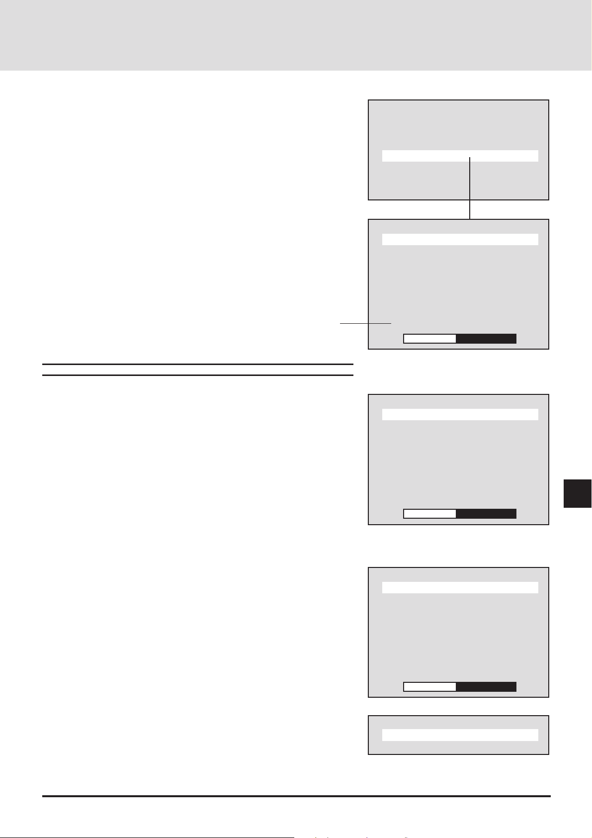
Default Settings of the Switcher
Picture settings at the time of shipping from the factory are as described below .
Please adjust and set required items.
Press the MENU button to display [Main Menu], select [Switcher] with the
cursor button, then press the ENTER button to display the switcher menu.
Setting at the time of shipping
from the factory is ‘Projector”.
Switcher Picture Adjustment
Main Menu
Picture
Alignment
Memory
Switcher
Display Menu
Settings Menu
Source
Switcher
R Gain
G Gain
B Gain
Color
Tint
Sharpness
Volume
Audio Select
–
+
Select [Switcher] from the main menu.
Press the cursor ▲/▼ button and select the adjustment item.
When the item to be adjusted is selected, the adjustment bar of the selected
item is displayed at the bottom edge of the display.
Adjust with the cursor § (–)/ © (+) button.
Returning the Picture Adjustment to the Standard Settings
This function returns the adjustments of the R, G, and B gains, the color, tint,
and sharpness to the standard settings.
Example: Return the R Gain to the Standard Setting.
Press the cursor ▲/▼ button and select [R Gain].
When the item to be adjusted is selected, the adjustment bar of the selected
item is displayed at the bottom edge of the display.
Press the NORMAL button. A verification display “Normalize ?” will appear.
Press the cursor ▲/▼ button, select Yes/No, then press the ENTER button.
The setting will return to the factory setting value of the switcher.
Switcher
R Gain
G Gain
B Gain
Color
Tint
Sharpness
Volume
Audio Select
–
Switcher
R Gain
G Gain
B Gain
Color
Tint
Sharpness
Volume
Audio Select
–
+32
+32
E-71
Normalize?
Yes
No
Page 72
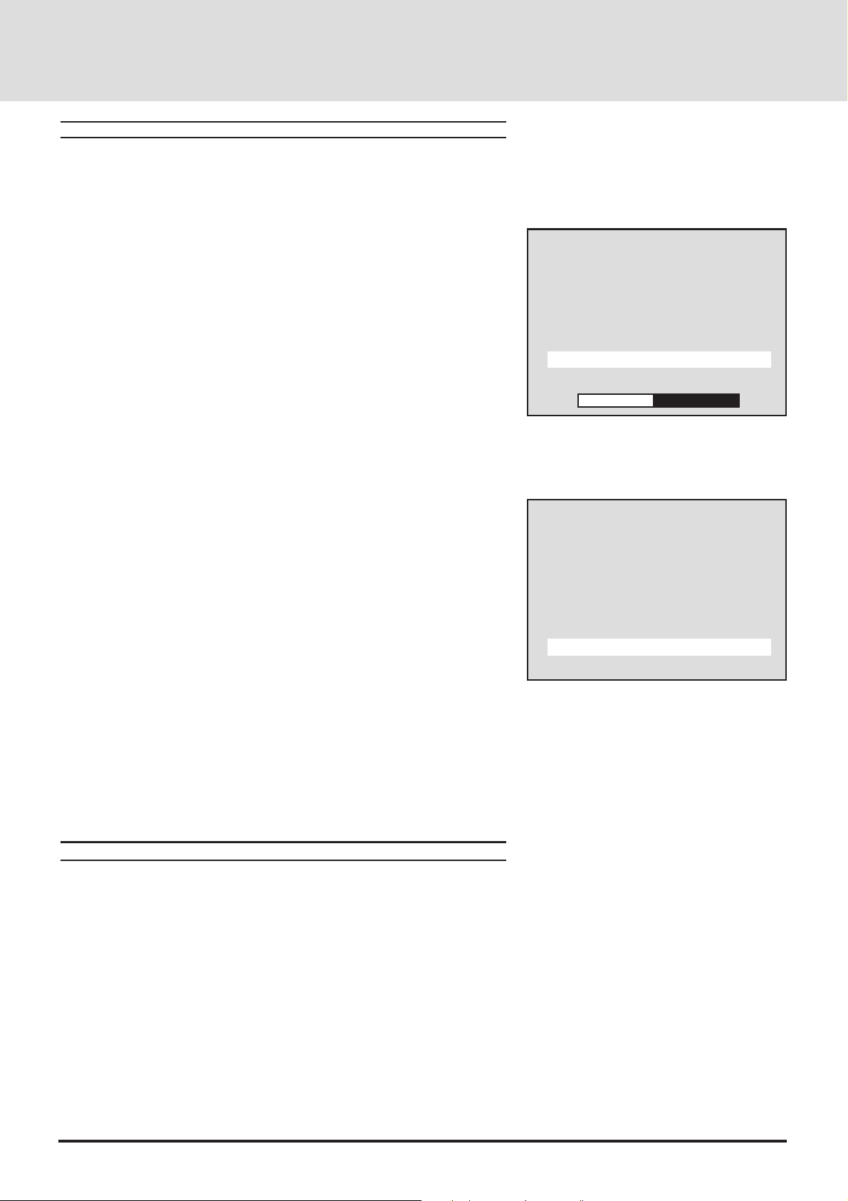
Audio Control of the Switcher
This is the audio adjustment of the switcher AUDIO OUTPUT.
Setting the Volume (V olume)
This function sets the volume adjustment data that corresponds to the slot.
Select [Switcher] from the main menu.
Press the cursor ▲/▼ button and select [Volume].
When the item to be adjusted is selected, the adjustment bar of the selected
item is displayed at the bottom edge of the display.
Adjust with the cursor § (–)/ © (+) button.
The adjustment range is from 0 to 63.
(–) Direction ..........The volume decreases.
(+) Direction ..........The volume increases.
Adjusting Volume of Switc her with Remote Control (Audio
Select)
This is a setting that adjusts the volume of the switcher with the VOLUME
button on the remote control.
Select [Switcher] → [Audio Select] of the main menu.
When the item to be adjusted is selected, the setting condition is displayed at
the bottom edge of the display.
A press of the ENTER button changes the display to the audio control display.
Press the cursor ▲/▼ button and select Switcher / Remote control.
Switcher................Permits volume adjustment of the switcher using the
VOLUME button of the remote control.
Projector ............... Permits volume adjustment of the projector using the
VOLUME button of the remote control.
Switcher
R Gain
G Gain
B Gain
Color
Tint
Sharpness
Volume
Audio Select
–
Switcher
R Gain
G Gain
B Gain
Color
Tint
Sharpness
Volume
Audio Select
Projector
+32
* The Switcher menu displays only when the switcher is connected with the
GT2000/GT2000R and Switcher Control mode is set to either SW 1 Level or
SW 2 Level.
Note:When the switcher is not connected, "Switcher" cannot be selected.
E-72
Page 73
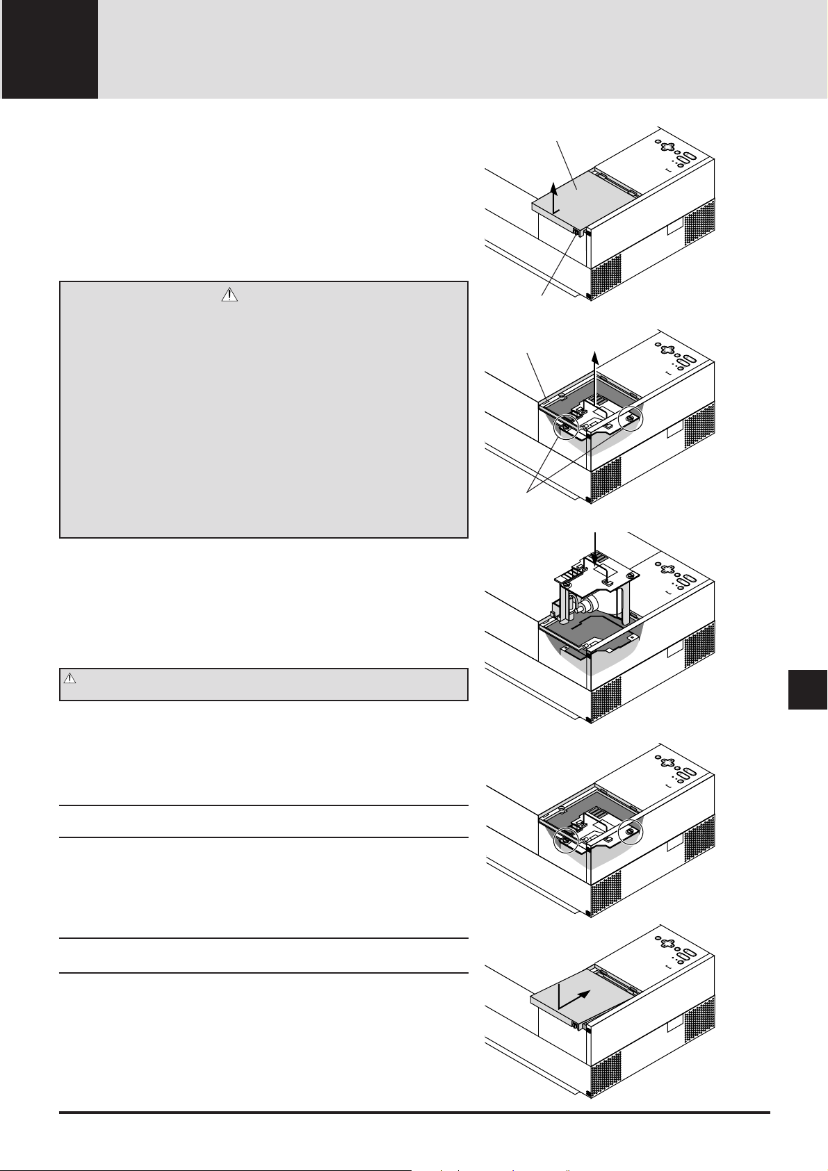
5 MAINTENANCE
This section describes the simple maintenance procedures you should follow
to replace the lamp, clean or replace the filter, and replace the batter ies in the
remote control.
Replacing The Lamp
After your lamp has been operating for 2000 hours or longer, the red
“status” light in the cabinet will go on and the lamp icon will appear on
the above right of the screen whenever the projector is turned on. The
lamp icon remains on after 2100 hours of service. Even though the lamp
may still be working, replace it at 2000 hours to maintain optimal projector performance.
CAUTION
• DO NOT TOUCH THE LAMP immediately after it has been used. It will be
extremely hot. Allow at least one hour for the lamp to cool before
handling.
• DO NOT REMOVE ANY SCREWS except the lamp cover set screw and
two lamp case screws. You could receive an electric shock.
• Do not touch the front sur face portion of the replacement lamp body in
which glass is used.
Touching the glass portion or bulb tip may result in a drop of the
brightness or shortened bulb life.
• Turn off the main power to the projector and disconnect the power cord.
Allow at least one hour for the lamp to cool.
• If you continue to use the lamp after 2000 hours of use, the lamp bulb may
shatter, and pieces of glass may be scattered in the lamp case. Do not
touch them as the pieces of glass may cause injury. If this happens,
contact your NEC dealer for lamp replacement.
T o replace the lamp:
1. Loosen the single captive screw that secures the lamp housing cover and
remove the cover.
2. Loosen the two captive scre ws securing the lamp case.
3. Remove the lamp by pulling out the complete assembly.
4. Install a new lamp case assembly and secure it in place with the two
captive screws.
CAUTION: Do not use a lamp other than the NEC replacement lamp.
Order this from your NEC dealer using your projector's model number .
5. Reattach the lamp housing cover and tighten the single captiv e screw.
6.
After you install a new lamp, select [Display] from the main menu, and press
the ENTER button. Then press the remote ▲/▼ button to select [Lamp
Usage], then press the NORMAL button to display the Reset menu. Press the
remote ▲/▼ button to select [Yes] and press the ENTER button.
This resets the lamp clock back to zero.
Note: When you replace the lamp, it is also wise to replace the filter. The
filter comes in the same package with your replacement lamp.
T o c hec k and reset the lamp usage time
T o view the lamp usage time:
1. Select [Display Menu] from the main menu and press the ENTER button.
2. Press the remote ▲/▼ button to select [Lamp Usage].
The usage time will be displayed at the bottom right of the menu.
Note: After your lamp has been operating for 2000, a warning icon will
appear.
Lamp housing cover
Captive screw
Interlock
Captive screw
Step 1
MEMU
SELECT
ENTER
FOCUS
ZOOM
STATUS
POWER
ON / OFF
Step 2
MEMU
SELECT
ENTER
FOCUS
ZOOM
STATUS
POWER
ON / OFF
Step 3
MEMU
SELECT
ENTER
FOCUS
ZOOM
STATUS
POWER
ON / OFF
MEMU
SELECT
MEMU
SELECT
Step 4
ENTER
FOCUS
ZOOM
STATUS
POWER
ON / OFF
Step 5
ENTER
FOCUS
ZOOM
STATUS
POWER
ON / OFF
T o r eset the lamp clock back to zero:
1. Select [Display] from the main menu, and press the ENTER button.
2. Press the remote ▲/▼ button to select [Lamp Usage], then press the
NORMAL button.
3.
Press the remote ▲/▼ b utton to select [Yes] and press the ENTER button.
This resets the lamp clock back to zero. Also the STATUS indicator goes off.
E-73
Page 74

Cleaning Or Replacing The Filter
The air-filter sponge keeps the inside of the MultiSync GT2000/
GT2000R LCD Projector free from dust or dirt and should be
cleaned after every 100 hours of operation (more often in dusty
conditions). If the filter is dirty or clogged, your projector may
overheat.
NOTE: Clean your filter after every 100 hours of operation.
CAUTION
• Turn off the main power and unplug the projector before
replacing the filter.
• Only clean the outside of the filter cover with a vacuum
cleaner.
• Do not attempt to operate the projector without a filter
cover.
• Y our LCD projector will not operate unless the filter co v er
is installed correctly .
T o c lean the air -filter:
Vacuum the filter through the filter co v er.
T o r eplace the air -f ilter:
1. Remove the filter cover by pushing up on the catch of the
cover until you feel it detach.
2. Reinstall the new filter cov er.
NOTE: Do not detach the sponge from the filter cover. Do not
wash the filter cover with soap and water. Soap and
water will damage the filter membrane.
Before replacing the filter cover, remove dust and dirt
from the projector cabinet. Keep out dust and dirt
during filter replacement.
ON / OFF
POWER
STATUS
ZOOM
-
FOCUS
ENTER
-
+
+
-
SELECT
MENU
+
AC IN
ON / OFF
POWER
STATUS
ZOOM
-
FOCUS
ENTER
-
+
+
-
SELECT
MENU
+
AC IN
Remote Control Battery Installation
Installing the Remote Control Batteries
When it comes time to replace the batteries, two "AAA" type
will be required.
1. Press and open the cover.
2. Align the batteries according to the (+) and (-)
indications inside the case.
3. Replace the cover.
E-74
Page 75

Cette section décrit les procédures simples d’entretien que vous aurez à suivre
pour remplacer la lampe, nettoyer ou remplacer le filtre et remplacer les piles
de la télécommande.
Remplacement de la lampe
Lorsque la lampe a été utilisée pendant 2000 heures ou plus, le voyant
“Status” (état) du coffret s’allume. Même si la lampe peut encore
fonctionner, remplacez-la au bout de 2000 heures pour conserver une
performance optimale de votre projecteur.
Couvercle de lampe
Etape 1
MEMU
SELECT
ENTER
FOCUS
ZOOM
STATUS
POWER
ON / OFF
PRECAUTION
• NE TOUCHEZ P AS A LA LAMPE juste après qu’elle a été utilisée . Elle
est très chaude. Laissez-la refoidir pendant au moins une heure avant de
la manipuler..
• NE RETIREZ AUCUNE VIS mis à part la vis qui fixe le couvercle de
lampe et les deux vis du compartiment de lampe. Vous risquez de
recevoir une déchar ge éléctrique.
• Mettez le projecteur hors circuit et débranchez le cordon d’alimentation.
Laissez refroidir la lampe pendant au moins une heure.
• Le projecteur s’éteindra et restera en attente après 2100 heures
d’utilisation. Dans ce cas, remplacez la lampe. Si vous continuez
d’utiliser la lampe après 2000 heures d’utilisation, l’ampoule peut se
briser et des brisures de verre peuvent être éparpillées dans le
compartiment de la lampe. Ne les touchez pas car elles peuvent vous
blesser. Dans ce cas, contactez v otre rev endeur NEC afin de procéder au
remplacement de la lampe.
Pour remplacer la lampe:
1. Retirez l’unique vis qui fixe le couvercle de lampe et retirez le couv ercle
2. Retirez les deux vis qui fixent le compartiment de lampe. (Afin de
prévenir contre un risque de décharge électrique, il y a un enclenchement
sur ce compartiment. Ne tentez pas de détourner cet enclenchement.)
3. Retirez la lampe en tirant tout l’assemblage.
4. Installez un nouvel assemblage de compartiment lampe et fixez-le a vec les
deux vis.
PRECAUTION: N’utilisez pas d’autres lampes qu’une lampe de rechange
NEC
Commandez-la auprès de votre vendeur NEC en donnant le numéro de
modèle du projecteur.
Vis
Enclenchement
Vis
Etape 2
MEMU
SELECT
ENTER
FOCUS
ZOOM
STATUS
POWER
ON / OFF
Etape 3
MEMU
SELECT
ENTER
FOCUS
ZOOM
STATUS
POWER
ON / OFF
MEMU
SELECT
Etape 4
ENTER
FOCUS
ZOOM
STATUS
POWER
ON / OFF
5. Fixez de nouveau le couvercle de lampe et replacez la vis unique.
6. Une fois la nouvelle lampe installée.
REMARQUE: Réinitialiser la durée totale d’ usa ge de lampe. (Se rperor ter
à la page E-73.)
REMARQUE: Lorsque vous remplacez la lampe , Lorsque vous r emplacez
la lampe, il est recommandé de changer également le filtre. Le filtre se
trouve dans le même emballage que la lampe de rechange .
E-75
MEMU
SELECT
Etape 5
ENTER
FOCUS
ZOOM
STATUS
POWER
ON / OFF
Page 76

Nettoyage ou remplacement du filtre
Le coussin éponge du filtre à air maintient l’intérieur du
projecteur à affichage à cristaux liquides MultiSync GT2000 /
GT2000R à l’abri de la poussière ou de la saleté et doit être
nettoyé toutes les 100 heures d’utilisation (plus souvent dans les
endroits poussiéreux). Si le filtre est sale ou bouché, le
projecteur risque de surchauffer .
REMARQUE: Nettoyez le filtre toutes les 100 heures
d’utilisation.
PRECAUTION
• Coupez l’alimentation et débranchez le projecteur avant
de remplacer le filtre.
• Nettoyez uniquement le couvercle extérieur du filtre avec
un aspirateur .
• N’essayez pas de faire fonctionner le projecteur sans
filtre.
• Votre projecteur à affichage à cristaux liquides ne
fonctionnera pas tant que le filtre ne sera pas installé
correctement.
Pour nettoyer le filtre à air:
Aspirez le filtre à travers le couv ercle de f iltre .
Pour remplacer le filtre à air:
1. Retirez le panneau du filtre en poussant vers le haut sur le
cliquet du couvercle à l’aide d’un tournevis à tête plate
jusqu’à ce que vous sentiez qu’il se détache.
2. Réinstallez le panneau du filtre.
ON / OFF
POWER
STATUS
ZOOM
-
FOCUS
ENTER
-
+
+
-
SELECT
MENU
+
AC IN
ON / OFF
POWER
STATUS
ZOOM
-
FOCUS
ENTER
-
+
+
-
SELECT
MENU
+
AC IN
REMARQUE: Ne détachez pas le coussin éponge du couvercle
de filtre. Ne lavez pas le filtre au savon et à l’eau.
Le savon et l’eau endommageront la membrane du
filtre.
Avant de remplacer le filtre à air, dépoussiérez et
nettoyez le coffret du projecteur. Maintenez
propre pendant le remplacement du filtre.
Installation des piles de la
télécommande
1. Appuyez fermement et retirez le couvercle des piles en le
faisant glisser.
2. Retirez les deux piles usagées et installez de nouvelles piles
(AA). Assurez-vous de respecter la polarité (+/–) des piles.
3. Remettez le couvercle des piles en le faisant glisser, jusqu’à
ce qu’il s’emboîte.
E-76
Page 77

TROUBLESHOOTING6
This section helps you resolve problems you may encounter while setting up or using your MultiSync GT2000/GT2000R LCD
Projector.
Status Light Messages
Red
Green
Condition
OFF
On continually
Blinking very rapidly
(On and off in a cycle of 1 sec.)
Blinking slowly
(On and off in a cycle of 8 sec.)
Blinking very slowly
(On and off in a cycle of 12 sec.)
On continually
Blinking very slowly
(On and off in a cycle of 12
sec)
Status
m Normal
m The projector lamp has exceeded 2000 hours of operation and
should be replaced.
m Either the lamp cover or f ilter cov er is not fastened pr operly.
Check each and reattach them if necessary .
m The cooling fan has stopped. Contact your NEC dealer for service.
m The lamp is not turned on.
• The projector was turned off and back on too quickly. Turn
off the projector, wait one minute, then turn the projector
back on. Or the lamp is burnt out.
m Normal (The projector is used with the ISS-6020 switcher in
bundled operation.)
m The projector is not connected with the ISS-6020.
E-77
Page 78

Common Problems & Solutions
Problem
Does not turn on
No picture
Image isn’t square to the screen
Picture is blurred
Check These Items
• Check that the cord is plugged in and that the power switch on the front panel is on.
• Ensure that the filter cover is installed correctly.
• Check to see if the projector has overheated or the lamp usage exceeds 2100 hours. If there is
insufficient ventilation around the projector or if the room where you're presenting is particularly
warm, move the projector to a cooler location. Check the filter and clean it if necessary.
• Select your source (Video, S-Video, RGB1, or RGB2).
• Ensure your cables are connected properly.
• Adjust the brightness and contrast.
• Remove the lens cap.
• Check if RGB/YCbCr mode is set to YCbCr when a DVD player with component output is
connected. (See page E-48.)
• Check if the Source Lock is set to Off. If not, select [Memory Edit] ->[Source Lock] and set to
Off. If the Source Lock is set to ON, search is not performed when you switch to another input.
(See page E-68.)
• Adjust alignment correctly when RGB input is selected. (See page E-49.)
• Reposition the projector to improve its angle to the screen.
• Correct the keystone distortion. (See page E-40.)
• Set Sync position to "0" or "1" to correct the wave pattern. (See page E-55.)
• Adjust the focus.
• Reposition the projector to improve its angle to the screen.
• Ensure that the distance between the projector and screen is within the adjustment range of the
lens.
• Condensation may form on the lens when the cold projector is brought into a warm place and is
turned on. Should this happen, let the projector stand until there is no condensation on the lens.
Image is scrolling vertically,
horizontally or both
Volume button does not work
Remote control does not work
Status indicator is lit or
blinking
Cross color in RGB mode
• Select the source you want to input.
• Make sure the recalled user memory or channel memory supports the current input signal.
(See page E-56.)
• Check if Audio Select is set to Switcher when the switcher is connected. (See page E-72.)
• Install new batteries. (See page E-74.)
• Make sure there are no obstacles between you and the projector.
• Stand within 7m of the projector.
• Check if the projector ID is the same as the remote ID. Or check if the remote ID is set to "00".
(See page E-43.)
See the Status Light message chart on page E-77.
Adjust the image with the Picture Adjustment and Fine Picture Adjustment.
E-78
Page 79

SPECIFICATIONS7
This section provides technical information about the MultiSync GT2000/GT2000R LCD Projector's performance.
Model Number GT2000 / GT2000R
Optical
LCD Panel 1.3", p-Si TFT active-matrix, 136621024 dots
Lens GT2000 : F 2.5 f = 52 – 68 mm (Power zoom, power focus)
GT2000R: F2.5 f = 30 mm (Fixed focus)
Lamp New short arc high pressure lamp 150 W
Image Size GT2000 : 20 – 300 inches (50.8 – 762 cm) diagonal
GT2000R : 40 – 200 inches (102 – 508 cm) diagonal
Projection Distance GT2000 : 1.0 – 12.0 m (3.08 - 39.37 ft)
GT2000R : 0.8 – 4.6 m (2.75 - 15.2 ft)
Electrical
Inputs Video (NTSC / PAL / SECAM / NTSC4.43)
RGB (H : 15 – 107 kHz, V : 50 – 105 Hz)
Video Bandwidth RGB: 150 MHz
Color Reproduction Full color, 16.7 million colors simultaneously.
Horizontal Resolution 550 TV lines at S-Video : NTSC / PAL
Power Requirement 100 – 120 / 220 – 240 VAC, 50 / 60 Hz
Input Current 5 / 2 A
Mechanical
Dimensions GT2000 : 29.3 cm (W)217. 1 cm (H)240. 5 cm (D) with lens
Net Weight GT2000 : 8. 0 kg / 17. 7 lbs
Operational Temperatures LCD projector: 0° to 40°C / 32° to 104° F, 20 – 80% humidity
Regulations UL Approved (UL 1950, CSA 950)
300 TV lines : SECAM / NTSC 4.43
1000 TV lines : Y/Cb/Cr
RGB 1366 dots horizontal, 1024 dots vertical
11. 6” (W)26. 8” (H)216. 0” (D) with lens
GT2000R : 29.3 cm (W)217.1 cm (H)247.8 cm (D) with lens
11. 6” (W)26. 8” (H)218. 9” (D) with lens
GT2000R : 10. 0 kg / 22. 1 lbs
Remote control: 0° to 60°C / 32° to 140° F
Meets DOC Canada requirements
Meets FCC Class A requirements
Meets EMC Directive (EN55022, EN61000-3-2, EN61000-3-3, EN50082-1)
Meets Low Voltage Directive (EN60950, TÜV GS Approved)
E-79
Page 80
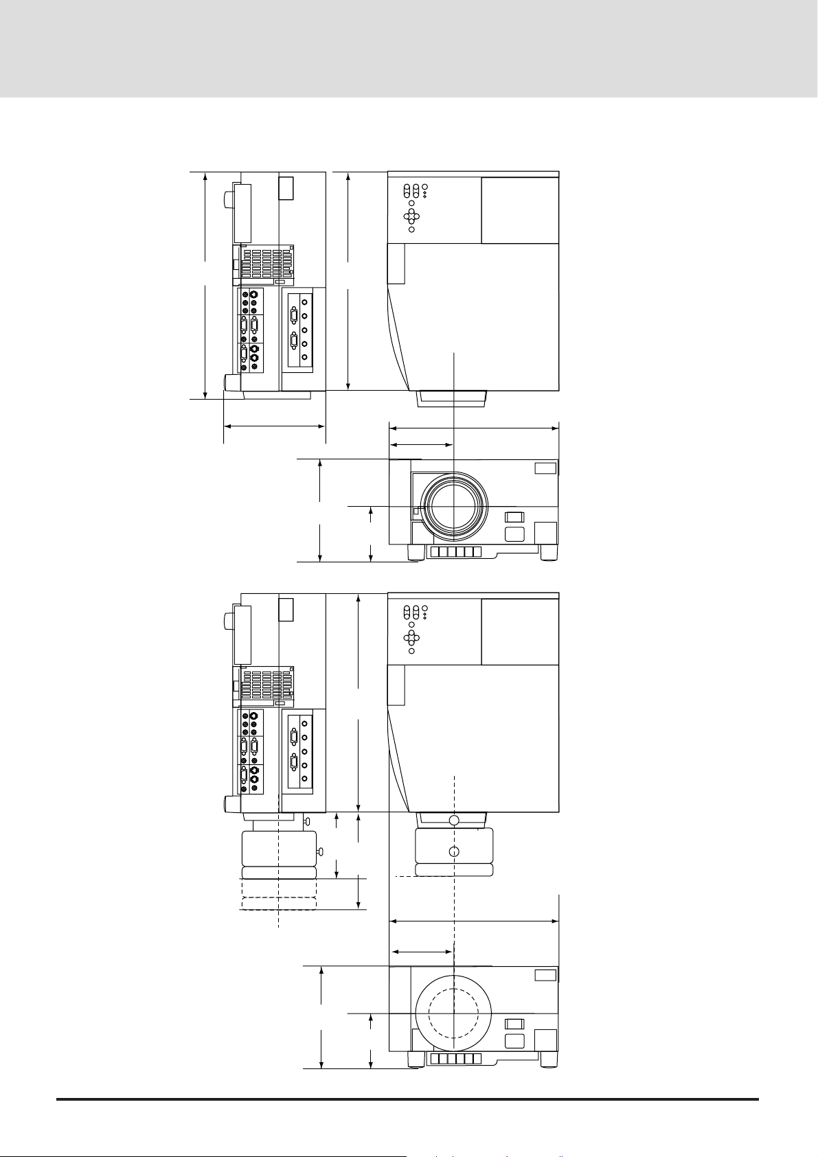
Cabinet Dimensions
GT2000
GT2000R
405
(16")
171
(6.7")
378
(15")
Lens center
92.2
(3.6")
111.5 (4.4")
Lens center
290 (11.4")
not including side protrusion
171
(6.7")
MAX.
95.76
(3.8")
378
(15")
MAX.
99.96
(3.9")
Lens center
84.2
(3.3")
111.5 (4.4")
Lens center
290 (11.4")
not including side protrusion
Unit : mm (inch)
E-80
Page 81
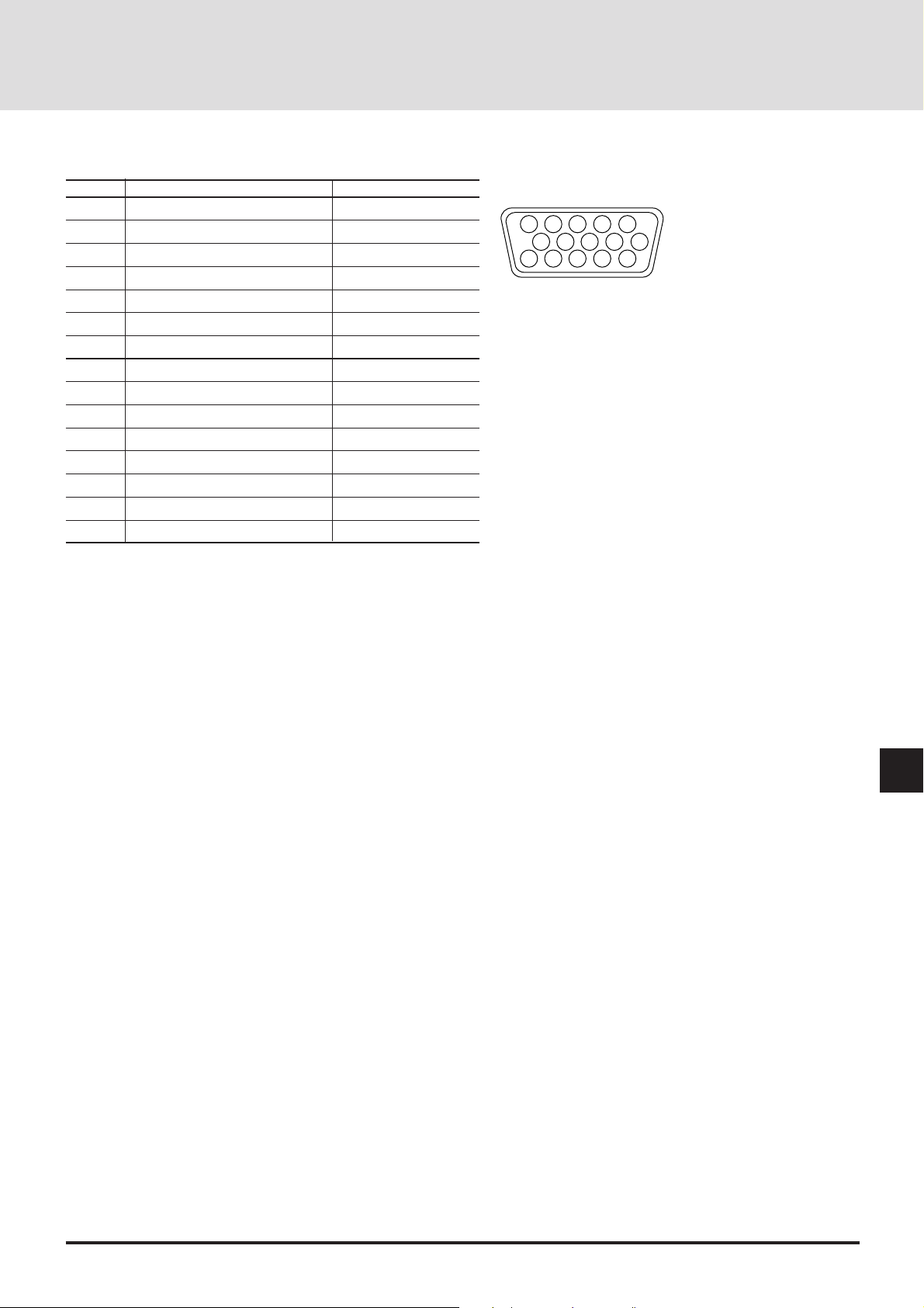
D-Sub Pin Assignments
1
2
34
5
11
12
13
1415
6
7
8
9
10
PC 15-Pin mini D-Sub
Pin No. RGB (Analog) YCbCr
1 Red Cr
2 Green or Sync. on Green Y
3 Blue Cb
4 GND
5 GND
6 Red Return (GND) Cr (GND)
7 Green Return (GND) Y (GND)
8 Blue Return (GND) Cb (GND)
9 No Connection
10 Sync Return (GND)
11 GND
12 Bi-dirctional DAT A (SDA)
13 H. or Composite sync
14 V. SYNC (VCLK)
15 Data Clock
Signal level
Video signal : 0.7 Vp-p (analog)
Sync. signal : TTL level
PC 15-Pin mini D-Sub
E-81
Page 82

Displayable Video Signals
The video signals that can be displayed with your LCD projector fall between a
horizontal frequency of 15 to 107 kHz, a vertical frequency of 50 to 105 Hz.
Typical workstations, personal computers, and video signals that can be projected are as follows:
Signal Resolution Horizontal Vertical
Frequency Frequency
NTSC 337 2 480 15.73 29.9
PAL/SECAM 372 2 574 15.63 25.0
HDTV 1920 2 517 33.75 25.0
640 2 480 31.5 60.0
800 2 600 37.9 60.3
800 2 600 46.9 75.0
1024 2 768 56.5 70.1
1024 2 768 60.0 75.0
1280 2 1024 64.6 59.9
640 2 480 37.9 72.8
640 2 480 37.5 75.0
IBM PC or 640 2 480 43.3 85.0
Compatibles 800 2 600 35.2 56.3
800 2 600 48.1 72.2
800 2 600 53.7 85.1
1024 2 768 48.4 60.0
1024 2 768 58.1 72.0
1024 2 768 68.7 85.0
1280 2 1024 80.0 75.0
1600 2 1200 75.0 60.0
1600 2 1200 81.3 65.0
1600 2 1200 87.5 70.0
Apple 640 2 480 35.0 66.7
Macintosh 832 2 624 49.7 74.5
1024 2 768 60.2 74.9*
1152 2 870 68.7 75.6*
1280 2 1024 81.1 76.1*
NEC EWS4800 1280 2 1024 64.6 59.9
1280 2 1024 75.1 71.0
Sun 1152 2 900 61.8 66.0
1280 2 1024 74.9 69.9
1280 2 1024 81.1 76.1
SGI 1024 2 768 49.7 60.4
1280 2 1024 63.9 60.0
1152 2 900 71.7 76.1
HP 1280 2 1024 78.1 72.0
* 160021200 images are compressed into
136621024 with AccuBlend .
E-82
Page 83

PC Control Command Reference
Command Codes
1. Power ON
[function] Switching ON the projector power
[Command] C0 00 01 00 CKS
[ACK] C0 00 01 00 CKS
2. Power OFF
[function] Switching OFF the projector power
[Command] C0 00 02 00 CKS
[ACK] C0 00 02 00 CKS
3. Focus
[function] Focus adjustment
[Command] C0 00 03 01 PARA CKS
[ACK] C0 00 03 00 CKS
"PARA=01:+, FF:-"
4. Zoom
[function] Zoom adjustment
[Command] C0 00 04 01 PARA CKS
[ACK] C0 00 04 00 CKS
"PARA=01:Wide, FF:Tele"
5. Digital Zoom
[function] Digital Magnifying function
[Command] C0 00 05 01 PARA CKS
[ACK] C0 00 05 00 CKS
"PARA=01:+, FF:-, 00:Off"
6. Key Cursor
[function] Cursor keys
[Command] C0 00 06 01 PARA CKS
[ACK] C0 00 06 00 CKS
"PARA=00:Up, 01:Down, 02:Right,
03:Left"
available at the time of Digital
Zoom only
7. Expand
[function] Digital Enlagement function
[Command] C0 00 07 01 PARA CKS
[ACK] C0 00 07 00 CKS
"PARA=00:Off, 01:On"
8. Input Select
[function] Video source selection
[Command] C0 00 08 01 PARA CKS
[ACK] C0 00 08 00 CKS
"PARA=00:RGB1, 01:RGB2, 02:VIDEO,
03:S-VIDEO"
9. Brightness
[function] Brightness adjustment
[Command] C0 00 09 01 DATA CKS
[ACK] C0 00 09 00 CKS
DATA= -31 - +32 (decimal)
10. Contrast
[function] Contrast adjustment
[Command] C0 00 0A 01 DATA CKS
[ACK] C0 00 0A 00 CKS
DATA= -31 - +32 (decimal)
11. V olume
[function] Volume adjustment
[Command] C0 00 0B 01 DATA CKS
[ACK] C0 00 0B 00 CKS
DATA= 00 - 63 (decimal)
12. Color
[function] Color adjustment
[Command] C0 00 0C 01 DATA CKS
[ACK] C0 00 0C 00 CKS
DATA= -31 - +32 (decimal)
13. Tint
[function] Tint adjustment
[Command] C0 00 0D 01 DATA CKS
[ACK] C0 00 0D 00 CKS
DATA= -31 - +32 (decimal)
14. Sharpness
[function] Sharpness adjustment
[Command] C0 00 0E 01 DATA CKS
[ACK] C0 00 0E 00 CKS
DATA= -31 - +32 (decimal)
15. Brightness R/G/B
[function] Brightness adjustment for RGB
[Command] C0 00 0F 02 RGB DATA CKS
[ACK] C0 00 0F 00 CKS
"RGB=00:R, 01:G, 02:B"
DATA= -31 - +32 (decimal)
16. Contrast R/G/B
[function] Contrast adjustment for RGB
[Command] C0 00 10 02 RGB DATA CKS
[ACK] C0 00 10 00 CKS
"RGB=00:R, 01:G, 02:B"
DATA= -31 - +32 (decimal)
17. Image Mode
[function] Image mode selection
[Command] C0 00 11 01 PARA CKS
[ACK] C0 00 11 00 CKS
"PARA=00:Normal, 01:Normal 1,
02:Normal 2,03:Normal 3, 04:Doc Cam"
18. Scan Mode
[function] Scan mode selection
[Command] C0 00 12 01 PARA CKS
[ACK] C0 00 12 00 CKS
"PARA=00:Auto, 01:Non Interlace,
02:Interlace Video, 03:Interlace
PC"
E-83
Page 84

19. Interpolation
[function] Interpolation selection
[Command] C0 00 13 01 PARA CKS
[ACK] C0 00 13 00 CKS
"PARA=00:PC Mode, 01:Video Mode"
20. Picture Normalize
[function] Picture normalization
[Command] C0 00 14 01 PARA CKS
[ACK] C0 00 14 00 CKS
"PARA=00:Brightness&Contrast,
01:Picture All Data"
21. H Position
[function] Horizontal display position ad
justment
[Command] C0 00 15 01 PARA CKS
[ACK] C0 00 15 00 CKS
"PARA=01:Right, FF:Left"
22. V Position
[function] Vertical display position adjust
ment
[Command] C0 00 16 01 PARA CKS
[ACK] C0 00 16 00 CKS
"PARA=01:Up, FF:Down"
23. Picture Adjust
[function] Clock frequency adjustment
[Command] C0 00 17 01 PARA CKS
[ACK] C0 00 17 00 CKS
"PARA=01:+, FF:-"
24. Fine Picture
[function] Horizontal phase adjustment
[Command] C0 00 18 01 PARA CKS
[ACK] C0 00 18 00 CKS
"PARA=01:+, FF:-"
25. H Amplitude
[function] Horizontal magnifying adjustment
[Command] C0 00 19 01 PARA CKS
[ACK] C0 00 19 00 CKS
"PARA=01:+, FF:-"
26. V Amplitude
[function] Vertical magnifying adjustment
[Command] C0 00 1A 01 PARA CKS
[ACK] C0 00 1A 00 CKS
"PARA=01:+, FF:-"
27. Image Filter
[function] Image Filter function
[Command] C0 00 1B 01 PARA CKS
[ACK] C0 00 1B 00 CKS
"PARA=00:Off, 01:On"
28. V Phase
[function] Vertical phase adjustment
[Command] C0 00 1C 01 PARA CKS
[ACK] C0 00 1C 00 CKS
"PARA=01:+, FF:-"
29. Skew Correction
[function] Skew adjustment
[Command] C0 00 1D 01 PARA CKS
[ACK] C0 00 1D 00 CKS
"PARA=01:+, FF:-"
30. Sync Position
[function] Sync position adjustment
[Command] C0 00 1E 01 PARA CKS
[ACK] C0 00 1E 00 CKS
"PARA=01:+, FF:–"
31. Clamp Timing
[function] Clamp timing selection
[Command] C0 00 1F 01 PARA CKS
[ACK] C0 00 1F 00 CKS
"PARA=01:+, FF:–"
32.RGB/YCbCr
[function] RGB/YCbCr selection
[Command] C0 00 20 01 PARA CKS
[ACK] C0 00 20 00 CKS
"PARA=00:RGB, 01:YCbCr"
33. Auto Alignment
[function] Automatic adjustment
[Command] C0 00 21 00 CKS
[ACK] C0 00 21 00 CKS
34. Projector Mute ON/OFF
[function] Projector mute ON/OFF
[Command] C0 00 22 02
[ACK] C0 00 22 00 CKS
"PARA=00:Picture, 01:Audio"
"DATA=00:Off, 01:On"
35. Memory Store
[function] Memory store
[Command] C0 00 23 02 MEM NO CKS
[ACK] C0 00 23 00 CKS
MEM:type of target storage
"=00:Channel Memory, 01:User
Memory"
NO:memory number for target
storage=00-99 (decimal)
PARA DATA CKS
E-84
Page 85

36. Memory Load
[function] Memory load
[Command] C0 00 24 02 MEM NO CKS
[ACK] C0 00 24 01 DATA CKS
MEM: type of memory to load
"=00:Channel Memory, 01:User
Memory"
NO:number for memory to load
=00 - 99 (decimal)
"DATA=01:OK, FF:No Data"
37. Memory Copy
[function] Memory copy
[Command] C0 00 25 04
[ACK] C0 00 25 01 DATA CKS
SRCMEM:type of memory to copy from
"=00:Channel Memory, 01:User
Memory"
SRCNO:number for memory to copy
from = 00 - 99 (decimal)
DESTMEM:type of memory to copy to
"=00:Channel Memory, 01:User
Memory"
DESTNO:number for memory to copy
to = 00 - 99 (decimal)
"DATA=01:OK, FF:No Data"
38. Memory Move
[function] Memory move
[Command] C0 00 26 04
[ACK] C0 00 26 01 DATA CKS
SRCMEM:type of memory to copy from
"=00:Channel Memory, 01:User
Memory"
SRCNO:number for memory to copy
from =00 - 99 (decimal)
DESTMEM:type of memory to copy to
"=00:Channel Memory, 01:User
Memory"
DESTNO:number for memory to copy
to =00 - 99 (decimal)
"DATA=01:OK, FF:No Data"
39. Memory Delete
[function] Memory delete
[Command] C0 00 27 03 MEM STARTNO ENDNO CKS
[ACK] C0 00 27 00 CKS
MEM:type of memory to be deleted
"=00:Channel Memory, 01:User
Memory"
STARTNO:number for memory to be
deleted (Start) =00 - 99 (decimal)
ENDNO:number for memory to be
deleted (End) =00 - 99 (decimal)
SRCMEM SRCNO DESTMEM DESTNO CKS
SRCMEM SRCNO DESTMEM DESTNO CKS
40. Change Default
[function] Changing default area
[Command] C0 00 28 00 CKS
[ACK] C0 00 28 00 CKS
41. Normalize Default Area
[function] Initializing default area
[Command] C0 00 29 00 CKS
[ACK] C0 00 29 00 CKS
42. Memory Edit(Name)
[function] Editing memory (name)
[Command]
[ACK] C0 00 2A 01 DATA CKS
43. Memory Edit(Slot)
[function] Editing memory (slot)
[Command]
[ACK] C0 00 2B 01 DATA CKS
44. Memory Edit(Image Mode)
[function] Editing memory (Image mode)
[Command]
[ACK] C0 00 2C 01 DATA CKS
C0 00 2A 0C MEM NO NAME1 NAME2 - NAME10 CKS
MEM:type of memory to edit
"=00:Channel Memory, 01:User
Memory"
NO:number for memory to edit
=00 - 99 (decimal)
NAME1 - NAME10:Memory Name(ASCII)
"DATA=01:OK, FF:No Data"
C0 00 2B 04 NO LEVEL MASTER SLAVE CKS
NO:number for memory to edit
=00 - 99 (decimal)
"LEVEL=00:Standalone,
01:SW 1 Level, 02:SW 2 Level"
MASTER=00 - 09
SLAVE=00 - 09
"DATA=01:OK, FF:No Data"
C0 00 2C 03 MEM NO IM CKS
MEM:type of memory to edit
"=00:Channel Memory, 01:User
Memory"
NO:number for memory to edit
=00 - 99 (decimal)
"IM=00:Normal, 01:Natural 1,
02:Natural 2, 03:Natural 3, 04:Doc
Cam"
"DATA=01:OK, FF:No Data"
E-85
Page 86

45. Memory Edit(Skip)
[function] Editing memory (Skip)
[Command] C0 00 2D 03 MEM NO PARA CKS
[ACK] C0 00 2D 01 DATA CKS
MEM:type of memory to edit
"=00:Channel Memory, 01:User
Memory"
NO:number for memory to edit
=00 - 99 (decimal)
"PARA=00:Off, 01:On"
"DATA=01:OK, FF:No Data"
46. Memory Edit(Source Lock)
[function] Editing (Lock)
[Command] C0 00 2E 03 MEM NO PARA CKS
[ACK] C0 00 2E 01 DATA CKS
MEM:type of memory to edit
"=00:Channel Memory, 01:User Memory"
NO:number for memory to edit
=00 - 99 (decimal)
"PARA=00:Off, 01:On"
"DATA=01:OK, FF:No Data"
47. Memory Edit(Sync Termination)
[function] Editing memory (Sync termination)
[Command] C0 00 2F 03 MEM NO PARA CKS
[ACK] C0 00 2F 01 DATA CKS
MEM:type of memory to edit
"=00:Channel Memory, 01:User Memory"
NO:number for memory to edit
=00 - 99 (decimal)
"PARA=00:75ohm, 01:Hi-Z"
"DATA=01:OK, FF:No Data"
48. Memory Information
[function] Information on memory
[Command]
[ACK] C0 00 30 0B DATA DATA1 DATA2 ... DATA10 CKS
C0 00 30 03 MEM NO PARA CKS
MEM:type of memory
"=00:Channel Memory, 01:User Memory"
NO:Memory number
=00 - 99 (decimal)
"PARA=00:Name, 01:Slot, 02:Image Mode,
03:Skip, 04:Source Lock"
05:Sync Termination
"DATA=01:OK, FF:No Data"
DATA1 - DATA10:Data
49. Standard Memory Search
50. Switcher Channel Select
51. Switcher Gain
52. Switcher Information
53. Switcher Normalize
54. Audio Select
55. Lamp Usage
[function] Force standard memory research
[Command] C0 00 31 00 CKS
[ACK] C0 00 31 00 CKS
[function] Selecting switcher channel
[Command] C0 00 32 01 CH CKS
[ACK] C0 00 32 00 CKS
CH=0 - 99 (decimal)
[function] Switcher gain adjustment
[Command] C0 00 33 02 PARA DATA CKS
[ACK] C0 00 33 00 CKS
"PARA=00:R Gain, 01:G Gain, 02:B
Gain, 03:Color, 04:Tint"
"05:Sharpness, 06:Volume"
DATA= 00 - 3F
[function] Switcher level adjustment
[Command] C0 00 34 01 PARA CKS
[ACK] C0 00 34 01 DATA CKS
"PARA=00:R Gain, 01:G Gain, 02:B
Gain, 03:Color, 04:Tint"
"05:Sharpness, 06:Audio,
07:Switcher Level, 08:Channel No.,
09:Audio Select"
DATA:Data
[function] Switcher normalization
[Command] C0 00 35 00 CKS
[ACK] C0 00 35 00 CKS
[function] Switching Audio Control
[Command] C0 00 36 01 PARA CKS
[ACK] C0 00 36 00 CKS
"PARA=00:Projector, 01:Switcher"
[function] Readout of lamp usage time
[Command] C0 00 37 00 CKS
[ACK] C0 00 37 03 TIME1 TIME2 MIN CKS
TIME1:Time(Low order)
TIME2:Time(High order)
MIN:Minute
E-86
Page 87

56. Lamp Usage Reset
[function] Resetting of lamp usage time
[Command] C0 00 38 00 CKS
[ACK] C0 00 38 00 CKS
57. Language
[function] On-screen language selection
[Command] C0 00 39 01 PARA CKS
[ACK] C0 00 39 00 CKS
"PARA=00:English, 01:German,
02:French, 03:Italian"
"04:Spanish, 05:Swedish, 06:Japanese"
58. Background
[function] Back ground color selection at time
of no signal
[Command] C0 00 3A 01 PARA CKS
[ACK] C0 00 3A 00 CKS
"PARA=00:Blue, 01:Black"
59. Auto Start
[function]
[Command] C0 00 3B 01 PARA CKS
[ACK] C0 00 3B 00 CKS
60. Auto Save
[function] Setting of Auto save
[Command] C0 00 3C 01 PARA CKS
[ACK] C0 00 3C 00 CKS
61. Onscreen Mute
[function] On-screen mute ON/OFF
[Command] C0 00 3D 01 PARA CKS
[ACK] C0 00 3D 00 CKS
62. Switcher Control
[function] Changing the number of switcher
[Command] C0 00 3E 01 PARA CKS
[ACK] C0 00 3E 00 CKS
63. Ext. Control
[function]
[Command] C0 00 3F 01 PARA CKS
[ACK] C0 00 3F 00 CKS
64. Projector ID
[function]
[Command] C0 00 40 01 PARA CKS
[ACK] C0 00 40 00 CKS
Setting of Automatic startup function
"PARA=00:Off, 01:On"
"PARA=00:Off, 01:On"
"PARA=00:Off, 01:On"
connected
"PARA=00:Standalone,
01:SW 1 Level, 02:SW 2 Level"
Enabling/disabling external control
"PARA=00:Off, 01:On"
Setting the projector' s ID number
PARA=00-64 (decimal)
65. Sync Termination
[function] Setting of sync termination
[Command] C0 00 41 01 PARA CKS
[ACK] C0 00 41 00 CKS
"PARA=00:75ohm, 01:Hi-Z"
66. Projection
[function]
[Command] C0 00 42 01 PARA CKS
[ACK] C0 00 42 00 CKS
67. Keystone
[function] Keystone correction
[Command] C0 00 43 01 DATA CKS
[ACK] C0 00 43 00 CKS
68. Keystone Save
[function]
[Command] C0 00 44 01 PARA CKS
[ACK] C0 00 44 00 CKS
69. PJ Condition Check
[function] Checking of projector' s status
[Command] C0 00 45 00 CKS
[ACK] C0 00 45 01 DATA CKS
70. PJ Condition Read
[function] Readout of projector's status
[Command] C0 00 46 01 PARA CKS
[ACK] C0 00 46 01 DATA CKS
Hexadecimal notation unless otherwise specified.
Setting of projector's orientation
"PARA=00:Front Floor, 01:Rear
Ceiling, 02:Rear Floor, 03:Front
Ceiling"
DATA= -31 - +32
Setting of Keystone save
"PARA=00:Off, 01:On"
"DATA=00:Standby, 02:PowerOn,
03:Cooling Down, 04:Error Standby"
"PARA=00:Brightness, 01:Contrast,
02:Volume, 03:Color, 04:Tint"
"05:Sharpness, 06:Image Mode,
07:Brightness R, 08:Brightness G"
"09:Brightness B, 0A:Contrast R,
0B:Contrast G, 0C:Contrast B"
"0D:Scan Mode, 0E:Interpolation,
0F:Image Filter, 10:Sync Position"
"11:Clamp Timing, 12:RGB/YCbCr,
13:Audio Select, 14:Language"
"15:Background, 16:Auto Start,
17:Auto Save, 18:Onscreen Mute"
"19:SW Control, 1A:Ext. Control,
1B:Sync Termination,
1C:Projection"
"1D:Keystone, 1E:Keystone Save,
1F:Input Source, 20:Picture Mute"
"21:Audio Mute, 22:Expand,
23:Source
DATA:Data
Lock"
E-87
 Loading...