

Page 1
®
NDA-24293
ISSUE 2
STOCK # 152017
General Description
SEPTEMBER, 2000
NEC America, Inc.
Page 2

LIABILITY DISCLAIMER
NEC America, Inc. reserves t he right to change th e specifications, functions, or
features, at any time, without notice.
NEC America, Inc. has prepared this document for use by its employees and
customers. The information contained herein is the property of NEC America,
Inc. and shall not be reproduced without prior written approval from NEC
America, Inc.
NEAX
®
and D
term®
are registered trademarks of NEC Corporation.
All other brand or product names are or may be trademarks or registered
trademarks of, and are used to identify products or services of their respective
owners.
Copyright 2000
NEC America, Inc.
Printed in the U.S.A
Page 3

NDA-24293
ISSUE 2
SEPTEMBER, 2000
NEAX2000 IVS
2
General Description
TABLE OF CONTENTS
Page
List of Figures . . . . . . . . . . . . . . . . . . . . . . . . . . . . . . . . . . . . . . . . . . . . . . . . . . . . . . . . . . . . x
List of Tables. . . . . . . . . . . . . . . . . . . . . . . . . . . . . . . . . . . . . . . . . . . . . . . . . . . . . . . . . . . . . xi
Regulatory Information . . . . . . . . . . . . . . . . . . . . . . . . . . . . . . . . . . . . . . . . . . . . . . . . . . . . .xiii
Regulatory Requirements . . . . . . . . . . . . . . . . . . . . . . . . . . . . . . . . . . . . . . . . . . . . . . . . . . . . . . xiii
FCC Part 15 Requirements . . . . . . . . . . . . . . . . . . . . . . . . . . . . . . . . . . . . . . . . . . . . . . . . . . . . . xiii
FCC Part 68 Registration. . . . . . . . . . . . . . . . . . . . . . . . . . . . . . . . . . . . . . . . . . . . . . . . . . . . . . . xiv
Company Notification. . . . . . . . . . . . . . . . . . . . . . . . . . . . . . . . . . . . . . . . . . . . . . . . . . . . . . . xiv
Service Requirements . . . . . . . . . . . . . . . . . . . . . . . . . . . . . . . . . . . . . . . . . . . . . . . . . . . . . . xiv
Location of FCC Compliance Labels . . . . . . . . . . . . . . . . . . . . . . . . . . . . . . . . . . . . . . . . . . . . . . xv
FCC Requirements for Private Line Operations. . . . . . . . . . . . . . . . . . . . . . . . . . . . . . . . . . . xv
Direct-Inward Dialing (DID) Calls. . . . . . . . . . . . . . . . . . . . . . . . . . . . . . . . . . . . . . . . . . . . . . . . . xvii
Regulatory Information On Single-line Analog Telephones. . . . . . . . . . . . . . . . . . . . . . . . . . . . . xviii
Hearing Aid Compatibility. . . . . . . . . . . . . . . . . . . . . . . . . . . . . . . . . . . . . . . . . . . . . . . . . . . . . . . xviii
Industry Canada CS-03 . . . . . . . . . . . . . . . . . . . . . . . . . . . . . . . . . . . . . . . . . . . . . . . . . . . . . . . . xviii
Safety Certifications. . . . . . . . . . . . . . . . . . . . . . . . . . . . . . . . . . . . . . . . . . . . . . . . . . . . . . . . . . . xx
Safety Considerations . . . . . . . . . . . . . . . . . . . . . . . . . . . . . . . . . . . . . . . . . . . . . . . . . . . . . . xx
Safety Instructions . . . . . . . . . . . . . . . . . . . . . . . . . . . . . . . . . . . . . . . . . . . . . . . . . . . . . . . . . . . . xxi
Chapter 1 Introduction. . . . . . . . . . . . . . . . . . . . . . . . . . . . . . . . . . . . . . . . . . . . . . . . . . . . 1
System Overview. . . . . . . . . . . . . . . . . . . . . . . . . . . . . . . . . . . . . . . . . . . . . . . . . . . . . . . . . . . . . 1
Feature Overview. . . . . . . . . . . . . . . . . . . . . . . . . . . . . . . . . . . . . . . . . . . . . . . . . . . . . . . . . . . . . 3
Hardware Architecture . . . . . . . . . . . . . . . . . . . . . . . . . . . . . . . . . . . . . . . . . . . . . . . . . . . . . . . . . 4
Hardware Modularity . . . . . . . . . . . . . . . . . . . . . . . . . . . . . . . . . . . . . . . . . . . . . . . . . . . . . . . 4
Flexible Interface Port . . . . . . . . . . . . . . . . . . . . . . . . . . . . . . . . . . . . . . . . . . . . . . . . . . . . . . 4
Cabling. . . . . . . . . . . . . . . . . . . . . . . . . . . . . . . . . . . . . . . . . . . . . . . . . . . . . . . . . . . . . . . . . . 5
Software Architecture. . . . . . . . . . . . . . . . . . . . . . . . . . . . . . . . . . . . . . . . . . . . . . . . . . . . . . . . . . 5
Fusion of RAM and ROM Programs . . . . . . . . . . . . . . . . . . . . . . . . . . . . . . . . . . . . . . . . . . . 5
Application Processors . . . . . . . . . . . . . . . . . . . . . . . . . . . . . . . . . . . . . . . . . . . . . . . . . . . . . 5
Feature Packages . . . . . . . . . . . . . . . . . . . . . . . . . . . . . . . . . . . . . . . . . . . . . . . . . . . . . . . . . 6
Feature Package Designations . . . . . . . . . . . . . . . . . . . . . . . . . . . . . . . . . . . . . . . . . . . . . . . 6
Software Licensing. . . . . . . . . . . . . . . . . . . . . . . . . . . . . . . . . . . . . . . . . . . . . . . . . . . . . . . . . 7
Integration . . . . . . . . . . . . . . . . . . . . . . . . . . . . . . . . . . . . . . . . . . . . . . . . . . . . . . . . . . . . . . . 7
Advantages . . . . . . . . . . . . . . . . . . . . . . . . . . . . . . . . . . . . . . . . . . . . . . . . . . . . . . . . . . . . . . . . . 7
Hardware Design . . . . . . . . . . . . . . . . . . . . . . . . . . . . . . . . . . . . . . . . . . . . . . . . . . . . . . . . . . 10
NEAX2000 IVS2 General Description
NDA-24293, Issue 2
Page i
Page 4

TABLE OF CONTENTS (CONTINUED)
Page
Chapter 2 System Configuration. . . . . . . . . . . . . . . . . . . . . . . . . . . . . . . . . . . . . . . . . . . . 11
Module Configuration. . . . . . . . . . . . . . . . . . . . . . . . . . . . . . . . . . . . . . . . . . . . . . . . . . . . . . . . . . 12
Installation Methods. . . . . . . . . . . . . . . . . . . . . . . . . . . . . . . . . . . . . . . . . . . . . . . . . . . . . . . . . . . 13
Technical Terms . . . . . . . . . . . . . . . . . . . . . . . . . . . . . . . . . . . . . . . . . . . . . . . . . . . . . . . . . . . . . 15
Trunking Diagram . . . . . . . . . . . . . . . . . . . . . . . . . . . . . . . . . . . . . . . . . . . . . . . . . . . . . . . . . . . . 16
Layout of PIM (SN1480 PIMF). . . . . . . . . . . . . . . . . . . . . . . . . . . . . . . . . . . . . . . . . . . . . . . . . . . 17
Control Card Mounting Conditions. . . . . . . . . . . . . . . . . . . . . . . . . . . . . . . . . . . . . . . . . . . . . . . . 18
Chapter 3 Terminals . . . . . . . . . . . . . . . . . . . . . . . . . . . . . . . . . . . . . . . . . . . . . . . . . . . . . 19
term
D
Series III . . . . . . . . . . . . . . . . . . . . . . . . . . . . . . . . . . . . . . . . . . . . . . . . . . . . . . . . . . . . . . . 19
Advantages of D
Dedicated Feature Keys. . . . . . . . . . . . . . . . . . . . . . . . . . . . . . . . . . . . . . . . . . . . . . . . . . . . . 20
term
D
Series III Accessories. . . . . . . . . . . . . . . . . . . . . . . . . . . . . . . . . . . . . . . . . . . . . . . . . . 20
term
D
Series III Terminals. . . . . . . . . . . . . . . . . . . . . . . . . . . . . . . . . . . . . . . . . . . . . . . . . . . . 21
Line Conditions of Each D
term
D
Series E . . . . . . . . . . . . . . . . . . . . . . . . . . . . . . . . . . . . . . . . . . . . . . . . . . . . . . . . . . . . . . . 26
Features. . . . . . . . . . . . . . . . . . . . . . . . . . . . . . . . . . . . . . . . . . . . . . . . . . . . . . . . . . . . . . . . . 26
term
D
Series E Terminals . . . . . . . . . . . . . . . . . . . . . . . . . . . . . . . . . . . . . . . . . . . . . . . . . . . . 27
Line Conditions of Each D
SN716 DESKCON. . . . . . . . . . . . . . . . . . . . . . . . . . . . . . . . . . . . . . . . . . . . . . . . . . . . . . . . . . . . 31
SN716 DESKCON Features . . . . . . . . . . . . . . . . . . . . . . . . . . . . . . . . . . . . . . . . . . . . . . . . . 32
Line Conditions of the SN716 DESKCON. . . . . . . . . . . . . . . . . . . . . . . . . . . . . . . . . . . . . . . 32
term
Series III . . . . . . . . . . . . . . . . . . . . . . . . . . . . . . . . . . . . . . . . . . . . . . . . 19
term
Series III Terminal . . . . . . . . . . . . . . . . . . . . . . . . . . . . . . . . . 25
term
Series E Terminal . . . . . . . . . . . . . . . . . . . . . . . . . . . . . . . . . 30
Chapter 4 Equipment Description. . . . . . . . . . . . . . . . . . . . . . . . . . . . . . . . . . . . . . . . . . . 33
Modules . . . . . . . . . . . . . . . . . . . . . . . . . . . . . . . . . . . . . . . . . . . . . . . . . . . . . . . . . . . . . . . . . . . . 33
Installation Hardware . . . . . . . . . . . . . . . . . . . . . . . . . . . . . . . . . . . . . . . . . . . . . . . . . . . . . . . . . . 33
Common Control . . . . . . . . . . . . . . . . . . . . . . . . . . . . . . . . . . . . . . . . . . . . . . . . . . . . . . . . . . . . . 33
Analog C.O. Trunk. . . . . . . . . . . . . . . . . . . . . . . . . . . . . . . . . . . . . . . . . . . . . . . . . . . . . . . . . . . . 34
Analog DID Trunk . . . . . . . . . . . . . . . . . . . . . . . . . . . . . . . . . . . . . . . . . . . . . . . . . . . . . . . . . . . . 34
Analog Tie Line Trunk . . . . . . . . . . . . . . . . . . . . . . . . . . . . . . . . . . . . . . . . . . . . . . . . . . . . . . . . . 34
Analog Station . . . . . . . . . . . . . . . . . . . . . . . . . . . . . . . . . . . . . . . . . . . . . . . . . . . . . . . . . . . . . . . 34
Digital Station. . . . . . . . . . . . . . . . . . . . . . . . . . . . . . . . . . . . . . . . . . . . . . . . . . . . . . . . . . . . . . . . 35
Digital Trunk. . . . . . . . . . . . . . . . . . . . . . . . . . . . . . . . . . . . . . . . . . . . . . . . . . . . . . . . . . . . . . . . . 35
Data . . . . . . . . . . . . . . . . . . . . . . . . . . . . . . . . . . . . . . . . . . . . . . . . . . . . . . . . . . . . . . . . . . . . . . 35
CCIS . . . . . . . . . . . . . . . . . . . . . . . . . . . . . . . . . . . . . . . . . . . . . . . . . . . . . . . . . . . . . . . . . . . . . . 35
ISDN/ECCIS . . . . . . . . . . . . . . . . . . . . . . . . . . . . . . . . . . . . . . . . . . . . . . . . . . . . . . . . . . . . . . . . 36
IP Trunk . . . . . . . . . . . . . . . . . . . . . . . . . . . . . . . . . . . . . . . . . . . . . . . . . . . . . . . . . . . . . . . . . . . . 36
Registers . . . . . . . . . . . . . . . . . . . . . . . . . . . . . . . . . . . . . . . . . . . . . . . . . . . . . . . . . . . . . . . . . . . 36
Miscellaneous Trunk . . . . . . . . . . . . . . . . . . . . . . . . . . . . . . . . . . . . . . . . . . . . . . . . . . . . . . . . . . 37
System I/O, OAI, ACD . . . . . . . . . . . . . . . . . . . . . . . . . . . . . . . . . . . . . . . . . . . . . . . . . . . . . . . . . 37
Voice Mail . . . . . . . . . . . . . . . . . . . . . . . . . . . . . . . . . . . . . . . . . . . . . . . . . . . . . . . . . . . . . . . . . . 37
Wireless. . . . . . . . . . . . . . . . . . . . . . . . . . . . . . . . . . . . . . . . . . . . . . . . . . . . . . . . . . . . . . . . . . . . 38
Remote PIM. . . . . . . . . . . . . . . . . . . . . . . . . . . . . . . . . . . . . . . . . . . . . . . . . . . . . . . . . . . . . . . . . 38
Optical Interface. . . . . . . . . . . . . . . . . . . . . . . . . . . . . . . . . . . . . . . . . . . . . . . . . . . . . . . . . . . . . . 38
Page ii
NEAX2000 IVS2 General Description
NDA-24293, Issue 2
Page 5

TABLE OF CONTENTS (CONTINUED)
Page
Chapter 5 Feature Description . . . . . . . . . . . . . . . . . . . . . . . . . . . . . . . . . . . . . . . . . . . . . 39
Account Code . . . . . . . . . . . . . . . . . . . . . . . . . . . . . . . . . . . . . . . . . . . . . . . . . . . . . . . . . . . . . . . 39
Add-On Module . . . . . . . . . . . . . . . . . . . . . . . . . . . . . . . . . . . . . . . . . . . . . . . . . . . . . . . . . . . . . . 39
Alarm Indications . . . . . . . . . . . . . . . . . . . . . . . . . . . . . . . . . . . . . . . . . . . . . . . . . . . . . . . . . . . . . 39
Alphanumeric Display . . . . . . . . . . . . . . . . . . . . . . . . . . . . . . . . . . . . . . . . . . . . . . . . . . . . . . . . . 39
Analog Port Adapter. . . . . . . . . . . . . . . . . . . . . . . . . . . . . . . . . . . . . . . . . . . . . . . . . . . . . . . . . . . 39
Announcement Service . . . . . . . . . . . . . . . . . . . . . . . . . . . . . . . . . . . . . . . . . . . . . . . . . . . . . . . . 40
Answer Key . . . . . . . . . . . . . . . . . . . . . . . . . . . . . . . . . . . . . . . . . . . . . . . . . . . . . . . . . . . . . . . . . 40
Attendant Assisted Calling. . . . . . . . . . . . . . . . . . . . . . . . . . . . . . . . . . . . . . . . . . . . . . . . . . . . . . 40
Attendant Camp-on . . . . . . . . . . . . . . . . . . . . . . . . . . . . . . . . . . . . . . . . . . . . . . . . . . . . . . . . . . . 40
Attendant Console . . . . . . . . . . . . . . . . . . . . . . . . . . . . . . . . . . . . . . . . . . . . . . . . . . . . . . . . . . . . 40
SN716 DESKCON . . . . . . . . . . . . . . . . . . . . . . . . . . . . . . . . . . . . . . . . . . . . . . . . . . . . . . . . . 40
Attendant Called/Calling Name Display. . . . . . . . . . . . . . . . . . . . . . . . . . . . . . . . . . . . . . . . . 40
Attendant Called/Calling Number. . . . . . . . . . . . . . . . . . . . . . . . . . . . . . . . . . . . . . . . . . . . . . 41
Attendant Call Selection. . . . . . . . . . . . . . . . . . . . . . . . . . . . . . . . . . . . . . . . . . . . . . . . . . . . . 41
Attendant Console Lockout - Password. . . . . . . . . . . . . . . . . . . . . . . . . . . . . . . . . . . . . . . . . 41
Attendant Do Not Disturb Setup And Cancel. . . . . . . . . . . . . . . . . . . . . . . . . . . . . . . . . . . . . 41
Attendant Interposition Calling/Transfer. . . . . . . . . . . . . . . . . . . . . . . . . . . . . . . . . . . . . . . . . 41
Attendant Lamp Check. . . . . . . . . . . . . . . . . . . . . . . . . . . . . . . . . . . . . . . . . . . . . . . . . . . . . . 41
Attendant Listed Directory Number . . . . . . . . . . . . . . . . . . . . . . . . . . . . . . . . . . . . . . . . . . . . 41
Attendant Loop Release . . . . . . . . . . . . . . . . . . . . . . . . . . . . . . . . . . . . . . . . . . . . . . . . . . . . 41
Attendant Programming. . . . . . . . . . . . . . . . . . . . . . . . . . . . . . . . . . . . . . . . . . . . . . . . . . . . . 41
Attendant Training Jacks . . . . . . . . . . . . . . . . . . . . . . . . . . . . . . . . . . . . . . . . . . . . . . . . . . . . 41
Audible Indication Control . . . . . . . . . . . . . . . . . . . . . . . . . . . . . . . . . . . . . . . . . . . . . . . . . . . 41
Call Processing Indication . . . . . . . . . . . . . . . . . . . . . . . . . . . . . . . . . . . . . . . . . . . . . . . . . . . 42
Call Queuing . . . . . . . . . . . . . . . . . . . . . . . . . . . . . . . . . . . . . . . . . . . . . . . . . . . . . . . . . . . . . 42
Call Splitting. . . . . . . . . . . . . . . . . . . . . . . . . . . . . . . . . . . . . . . . . . . . . . . . . . . . . . . . . . . . . . 42
Call Waiting Display. . . . . . . . . . . . . . . . . . . . . . . . . . . . . . . . . . . . . . . . . . . . . . . . . . . . . . . . 42
Common Route Indial . . . . . . . . . . . . . . . . . . . . . . . . . . . . . . . . . . . . . . . . . . . . . . . . . . . . . . 42
Dialed Number Identification Service (DNIS). . . . . . . . . . . . . . . . . . . . . . . . . . . . . . . . . . . . . 42
Incoming Call Identification . . . . . . . . . . . . . . . . . . . . . . . . . . . . . . . . . . . . . . . . . . . . . . . . . . 42
Individual Trunk Access . . . . . . . . . . . . . . . . . . . . . . . . . . . . . . . . . . . . . . . . . . . . . . . . . . . . . 42
Multi-Function Key . . . . . . . . . . . . . . . . . . . . . . . . . . . . . . . . . . . . . . . . . . . . . . . . . . . . . . . . . 42
Multiple Console Operation . . . . . . . . . . . . . . . . . . . . . . . . . . . . . . . . . . . . . . . . . . . . . . . . . . 42
Pushbutton Calling - Attendant Only . . . . . . . . . . . . . . . . . . . . . . . . . . . . . . . . . . . . . . . . . . . 43
Serial Call. . . . . . . . . . . . . . . . . . . . . . . . . . . . . . . . . . . . . . . . . . . . . . . . . . . . . . . . . . . . . . . . 43
Time Display . . . . . . . . . . . . . . . . . . . . . . . . . . . . . . . . . . . . . . . . . . . . . . . . . . . . . . . . . . . . . 43
Trunk Group Busy Display . . . . . . . . . . . . . . . . . . . . . . . . . . . . . . . . . . . . . . . . . . . . . . . . . . . 43
Unsupervised Trunk-to-Trunk Transfer By Attendant . . . . . . . . . . . . . . . . . . . . . . . . . . . . . . . 43
Attendant Delay Announcement . . . . . . . . . . . . . . . . . . . . . . . . . . . . . . . . . . . . . . . . . . . . . . . . . 43
Attendant Lockout . . . . . . . . . . . . . . . . . . . . . . . . . . . . . . . . . . . . . . . . . . . . . . . . . . . . . . . . . . . . 43
Attendant Overflow . . . . . . . . . . . . . . . . . . . . . . . . . . . . . . . . . . . . . . . . . . . . . . . . . . . . . . . . . . . 43
Attendant Override. . . . . . . . . . . . . . . . . . . . . . . . . . . . . . . . . . . . . . . . . . . . . . . . . . . . . . . . . . . . 43
Authorization Code . . . . . . . . . . . . . . . . . . . . . . . . . . . . . . . . . . . . . . . . . . . . . . . . . . . . . . . . . . . 44
Automated Attendant. . . . . . . . . . . . . . . . . . . . . . . . . . . . . . . . . . . . . . . . . . . . . . . . . . . . . . . . . . 44
NEAX2000 IVS2 General Description
NDA-24293, Issue 2
Page iii
Page 6

TABLE OF CONTENTS (CONTINUED)
Page
Automatic Call Distribution (ACD) . . . . . . . . . . . . . . . . . . . . . . . . . . . . . . . . . . . . . . . . . . . . . . . . 44
Busy In/Busy Out - ACD. . . . . . . . . . . . . . . . . . . . . . . . . . . . . . . . . . . . . . . . . . . . . . . . . . . . . 44
Call Waiting Indication - ACD. . . . . . . . . . . . . . . . . . . . . . . . . . . . . . . . . . . . . . . . . . . . . . . . . 44
Delay Announcement - ACD . . . . . . . . . . . . . . . . . . . . . . . . . . . . . . . . . . . . . . . . . . . . . . . . . 44
Hunt Past No Answer - ACD . . . . . . . . . . . . . . . . . . . . . . . . . . . . . . . . . . . . . . . . . . . . . . . . . 44
Immediate Overflow - ACD. . . . . . . . . . . . . . . . . . . . . . . . . . . . . . . . . . . . . . . . . . . . . . . . . . . 44
Priority Queuing - ACD . . . . . . . . . . . . . . . . . . . . . . . . . . . . . . . . . . . . . . . . . . . . . . . . . . . . . 44
Queue Size Control - ACD. . . . . . . . . . . . . . . . . . . . . . . . . . . . . . . . . . . . . . . . . . . . . . . . . . . 45
Silent Monitor - ACD . . . . . . . . . . . . . . . . . . . . . . . . . . . . . . . . . . . . . . . . . . . . . . . . . . . . . . . 45
Automatic Call Distribution with Management Information System (MIS) . . . . . . . . . . . . . . . . . . 45
Automatic Camp-on. . . . . . . . . . . . . . . . . . . . . . . . . . . . . . . . . . . . . . . . . . . . . . . . . . . . . . . . . . . 45
Automatic Number Identification (ANI). . . . . . . . . . . . . . . . . . . . . . . . . . . . . . . . . . . . . . . . . . . . . 45
Automatic Recall . . . . . . . . . . . . . . . . . . . . . . . . . . . . . . . . . . . . . . . . . . . . . . . . . . . . . . . . . . . . . 45
Automatic Wake-up . . . . . . . . . . . . . . . . . . . . . . . . . . . . . . . . . . . . . . . . . . . . . . . . . . . . . . . . . . . 45
Background Music . . . . . . . . . . . . . . . . . . . . . . . . . . . . . . . . . . . . . . . . . . . . . . . . . . . . . . . . . . . . 46
Boss / Secretary Calling. . . . . . . . . . . . . . . . . . . . . . . . . . . . . . . . . . . . . . . . . . . . . . . . . . . . . . . . 46
Broker's Call. . . . . . . . . . . . . . . . . . . . . . . . . . . . . . . . . . . . . . . . . . . . . . . . . . . . . . . . . . . . . . . . . 46
Call Back . . . . . . . . . . . . . . . . . . . . . . . . . . . . . . . . . . . . . . . . . . . . . . . . . . . . . . . . . . . . . . . . . . . 46
Call Forwarding . . . . . . . . . . . . . . . . . . . . . . . . . . . . . . . . . . . . . . . . . . . . . . . . . . . . . . . . . . . . . . 46
Attendant Call Forwarding Set-up and Cancel. . . . . . . . . . . . . . . . . . . . . . . . . . . . . . . . . . . . 47
Call Forwarding - All Calls . . . . . . . . . . . . . . . . . . . . . . . . . . . . . . . . . . . . . . . . . . . . . . . . . . . 47
Call Forwarding - Busy Line. . . . . . . . . . . . . . . . . . . . . . . . . . . . . . . . . . . . . . . . . . . . . . . . . . 47
Call Forwarding - No Answer. . . . . . . . . . . . . . . . . . . . . . . . . . . . . . . . . . . . . . . . . . . . . . . . . 47
Call Forwarding - Destination. . . . . . . . . . . . . . . . . . . . . . . . . . . . . . . . . . . . . . . . . . . . . . . . . 47
Multiple Call Forwarding - All Calls . . . . . . . . . . . . . . . . . . . . . . . . . . . . . . . . . . . . . . . . . . . . 47
Multiple Call Forwarding - Busy Line . . . . . . . . . . . . . . . . . . . . . . . . . . . . . . . . . . . . . . . . . . . 47
Multiple Call Forwarding - No Answer . . . . . . . . . . . . . . . . . . . . . . . . . . . . . . . . . . . . . . . . . . 47
Split Call Forwarding - All Calls . . . . . . . . . . . . . . . . . . . . . . . . . . . . . . . . . . . . . . . . . . . . . . . 47
Split Call Forwarding - Busy Line. . . . . . . . . . . . . . . . . . . . . . . . . . . . . . . . . . . . . . . . . . . . . . 47
Split Call Forwarding - No Answer. . . . . . . . . . . . . . . . . . . . . . . . . . . . . . . . . . . . . . . . . . . . . 48
Call Forwarding - Override. . . . . . . . . . . . . . . . . . . . . . . . . . . . . . . . . . . . . . . . . . . . . . . . . . . 48
Group Diversion. . . . . . . . . . . . . . . . . . . . . . . . . . . . . . . . . . . . . . . . . . . . . . . . . . . . . . . . . . . 48
Call Park . . . . . . . . . . . . . . . . . . . . . . . . . . . . . . . . . . . . . . . . . . . . . . . . . . . . . . . . . . . . . . . . . . . 48
Call Park - System . . . . . . . . . . . . . . . . . . . . . . . . . . . . . . . . . . . . . . . . . . . . . . . . . . . . . . . . . 48
Call Park - Tenant. . . . . . . . . . . . . . . . . . . . . . . . . . . . . . . . . . . . . . . . . . . . . . . . . . . . . . . . . . 48
Call Pickup. . . . . . . . . . . . . . . . . . . . . . . . . . . . . . . . . . . . . . . . . . . . . . . . . . . . . . . . . . . . . . . . . . 48
Call Pickup - Direct. . . . . . . . . . . . . . . . . . . . . . . . . . . . . . . . . . . . . . . . . . . . . . . . . . . . . . . . . 48
Call Pickup - Group . . . . . . . . . . . . . . . . . . . . . . . . . . . . . . . . . . . . . . . . . . . . . . . . . . . . . . . . 48
Call Pickup - Designated Group. . . . . . . . . . . . . . . . . . . . . . . . . . . . . . . . . . . . . . . . . . . . . . . 48
Call Redirect . . . . . . . . . . . . . . . . . . . . . . . . . . . . . . . . . . . . . . . . . . . . . . . . . . . . . . . . . . . . . . . . 49
Call Transfer . . . . . . . . . . . . . . . . . . . . . . . . . . . . . . . . . . . . . . . . . . . . . . . . . . . . . . . . . . . . . . . . 49
Call Transfer - Al lCalls. . . . . . . . . . . . . . . . . . . . . . . . . . . . . . . . . . . . . . . . . . . . . . . . . . . . . . 49
Call Transfer - Attendant. . . . . . . . . . . . . . . . . . . . . . . . . . . . . . . . . . . . . . . . . . . . . . . . . . . . . 49
Caller ID Class. . . . . . . . . . . . . . . . . . . . . . . . . . . . . . . . . . . . . . . . . . . . . . . . . . . . . . . . . . . . . . . 49
Caller ID Display . . . . . . . . . . . . . . . . . . . . . . . . . . . . . . . . . . . . . . . . . . . . . . . . . . . . . . . . . . . . . 49
Camp-on . . . . . . . . . . . . . . . . . . . . . . . . . . . . . . . . . . . . . . . . . . . . . . . . . . . . . . . . . . . . . . . . . . . 49
Page iv
NEAX2000 IVS2 General Description
NDA-24293, Issue 2
Page 7

TABLE OF CONTENTS (CONTINUED)
Page
Centrex Compatibility. . . . . . . . . . . . . . . . . . . . . . . . . . . . . . . . . . . . . . . . . . . . . . . . . . . . . . . . . . 49
Check In / Check Out. . . . . . . . . . . . . . . . . . . . . . . . . . . . . . . . . . . . . . . . . . . . . . . . . . . . . . . . . . 50
Class of Service. . . . . . . . . . . . . . . . . . . . . . . . . . . . . . . . . . . . . . . . . . . . . . . . . . . . . . . . . . . . . . 50
Code Restriction . . . . . . . . . . . . . . . . . . . . . . . . . . . . . . . . . . . . . . . . . . . . . . . . . . . . . . . . . . . . . 50
Conference (Three/Four Party) . . . . . . . . . . . . . . . . . . . . . . . . . . . . . . . . . . . . . . . . . . . . . . . . . . 50
Conference (Six/Ten Party) . . . . . . . . . . . . . . . . . . . . . . . . . . . . . . . . . . . . . . . . . . . . . . . . . . . . . 50
Consecutive Speed Dialing . . . . . . . . . . . . . . . . . . . . . . . . . . . . . . . . . . . . . . . . . . . . . . . . . . . . . 50
Consultation Hold. . . . . . . . . . . . . . . . . . . . . . . . . . . . . . . . . . . . . . . . . . . . . . . . . . . . . . . . . . . . . 51
Customer Administration Terminal (CAT) . . . . . . . . . . . . . . . . . . . . . . . . . . . . . . . . . . . . . . . . . . 51
Data Line Security . . . . . . . . . . . . . . . . . . . . . . . . . . . . . . . . . . . . . . . . . . . . . . . . . . . . . . . . . . . . 51
Delayed Ringing. . . . . . . . . . . . . . . . . . . . . . . . . . . . . . . . . . . . . . . . . . . . . . . . . . . . . . . . . . . . . . 51
Diagnostics . . . . . . . . . . . . . . . . . . . . . . . . . . . . . . . . . . . . . . . . . . . . . . . . . . . . . . . . . . . . . . . . . 51
Dial By Name. . . . . . . . . . . . . . . . . . . . . . . . . . . . . . . . . . . . . . . . . . . . . . . . . . . . . . . . . . . . . . . . 51
Dial Conversion . . . . . . . . . . . . . . . . . . . . . . . . . . . . . . . . . . . . . . . . . . . . . . . . . . . . . . . . . . . . . . 51
Direct Data Entry . . . . . . . . . . . . . . . . . . . . . . . . . . . . . . . . . . . . . . . . . . . . . . . . . . . . . . . . . . . . . 52
Direct Digital Interface . . . . . . . . . . . . . . . . . . . . . . . . . . . . . . . . . . . . . . . . . . . . . . . . . . . . . . . . . 52
Direct Inward Dialing (DID) . . . . . . . . . . . . . . . . . . . . . . . . . . . . . . . . . . . . . . . . . . . . . . . . . . . . . 52
DID Call Waiting. . . . . . . . . . . . . . . . . . . . . . . . . . . . . . . . . . . . . . . . . . . . . . . . . . . . . . . . . . . 52
DID Digit Conversion . . . . . . . . . . . . . . . . . . . . . . . . . . . . . . . . . . . . . . . . . . . . . . . . . . . . . . . 52
Direct Inward System Access (DISA) . . . . . . . . . . . . . . . . . . . . . . . . . . . . . . . . . . . . . . . . . . . . . 52
Direct Inward Termination (DIT). . . . . . . . . . . . . . . . . . . . . . . . . . . . . . . . . . . . . . . . . . . . . . . . . . 52
Direct Outward Dialing (DOD) . . . . . . . . . . . . . . . . . . . . . . . . . . . . . . . . . . . . . . . . . . . . . . . . . . . 52
Direct Station Selection/Busy Lamp Field (DSS/BLF) Console. . . . . . . . . . . . . . . . . . . . . . . . . . 53
Busy Out Status Console. . . . . . . . . . . . . . . . . . . . . . . . . . . . . . . . . . . . . . . . . . . . . . . . . . . . 53
Do Not Disturb Console . . . . . . . . . . . . . . . . . . . . . . . . . . . . . . . . . . . . . . . . . . . . . . . . . . . . . 53
Message Waiting Console . . . . . . . . . . . . . . . . . . . . . . . . . . . . . . . . . . . . . . . . . . . . . . . . . . . 53
Room Cutoff Console. . . . . . . . . . . . . . . . . . . . . . . . . . . . . . . . . . . . . . . . . . . . . . . . . . . . . . . 53
Wake Up No Answer Console . . . . . . . . . . . . . . . . . . . . . . . . . . . . . . . . . . . . . . . . . . . . . . . . 53
Distinctive Ringing . . . . . . . . . . . . . . . . . . . . . . . . . . . . . . . . . . . . . . . . . . . . . . . . . . . . . . . . . . . . 54
Do Not Disturb . . . . . . . . . . . . . . . . . . . . . . . . . . . . . . . . . . . . . . . . . . . . . . . . . . . . . . . . . . . . . . . 54
Do Not Disturb - Hotel/Motel . . . . . . . . . . . . . . . . . . . . . . . . . . . . . . . . . . . . . . . . . . . . . . . . . 54
Do Not Disturb-System . . . . . . . . . . . . . . . . . . . . . . . . . . . . . . . . . . . . . . . . . . . . . . . . . . . . . 54
Elapsed Call Timer. . . . . . . . . . . . . . . . . . . . . . . . . . . . . . . . . . . . . . . . . . . . . . . . . . . . . . . . . . . . 54
Enhanced 911 . . . . . . . . . . . . . . . . . . . . . . . . . . . . . . . . . . . . . . . . . . . . . . . . . . . . . . . . . . . . . . . 54
Executive Calling . . . . . . . . . . . . . . . . . . . . . . . . . . . . . . . . . . . . . . . . . . . . . . . . . . . . . . . . . . . . . 54
Executive Override. . . . . . . . . . . . . . . . . . . . . . . . . . . . . . . . . . . . . . . . . . . . . . . . . . . . . . . . . . . . 55
External Paging with Meet-Me. . . . . . . . . . . . . . . . . . . . . . . . . . . . . . . . . . . . . . . . . . . . . . . . . . . 55
Fax Arrival Indicator. . . . . . . . . . . . . . . . . . . . . . . . . . . . . . . . . . . . . . . . . . . . . . . . . . . . . . . . . . . 55
Feature Activation from Secondary Extension. . . . . . . . . . . . . . . . . . . . . . . . . . . . . . . . . . . . . . . 55
Flexible Line Key Assignment . . . . . . . . . . . . . . . . . . . . . . . . . . . . . . . . . . . . . . . . . . . . . . . . . . . 55
Flexible Numbering Plan . . . . . . . . . . . . . . . . . . . . . . . . . . . . . . . . . . . . . . . . . . . . . . . . . . . . . . . 55
Flexible Ringing Assignment . . . . . . . . . . . . . . . . . . . . . . . . . . . . . . . . . . . . . . . . . . . . . . . . . . . . 55
Forced Account Code . . . . . . . . . . . . . . . . . . . . . . . . . . . . . . . . . . . . . . . . . . . . . . . . . . . . . . . . . 56
Group Call . . . . . . . . . . . . . . . . . . . . . . . . . . . . . . . . . . . . . . . . . . . . . . . . . . . . . . . . . . . . . . . . . . 56
Automatic Conference (6/10 Party) . . . . . . . . . . . . . . . . . . . . . . . . . . . . . . . . . . . . . . . . . . . . 56
2 Way Calling. . . . . . . . . . . . . . . . . . . . . . . . . . . . . . . . . . . . . . . . . . . . . . . . . . . . . . . . . . . . . 56
NEAX2000 IVS2 General Description
NDA-24293, Issue 2
Page v
Page 8

TABLE OF CONTENTS (CONTINUED)
Page
Group Listening . . . . . . . . . . . . . . . . . . . . . . . . . . . . . . . . . . . . . . . . . . . . . . . . . . . . . . . . . . . . . . 56
Hands-free Answerback. . . . . . . . . . . . . . . . . . . . . . . . . . . . . . . . . . . . . . . . . . . . . . . . . . . . . . . . 56
Hands-free Dialing and Monitoring . . . . . . . . . . . . . . . . . . . . . . . . . . . . . . . . . . . . . . . . . . . . . . . 56
Hold . . . . . . . . . . . . . . . . . . . . . . . . . . . . . . . . . . . . . . . . . . . . . . . . . . . . . . . . . . . . . . . . . . . . . . . 56
Call Hold . . . . . . . . . . . . . . . . . . . . . . . . . . . . . . . . . . . . . . . . . . . . . . . . . . . . . . . . . . . . . . . . 56
Dual Hold . . . . . . . . . . . . . . . . . . . . . . . . . . . . . . . . . . . . . . . . . . . . . . . . . . . . . . . . . . . . . . . . 57
Exclusive Hold . . . . . . . . . . . . . . . . . . . . . . . . . . . . . . . . . . . . . . . . . . . . . . . . . . . . . . . . . . . . 57
Non-exclusive Hold . . . . . . . . . . . . . . . . . . . . . . . . . . . . . . . . . . . . . . . . . . . . . . . . . . . . . . . . 57
Hotel/Motel Attendant Console . . . . . . . . . . . . . . . . . . . . . . . . . . . . . . . . . . . . . . . . . . . . . . . . . . 57
Hotel/Motel Front Desk Instrument . . . . . . . . . . . . . . . . . . . . . . . . . . . . . . . . . . . . . . . . . . . . . . . 57
Hotline - Inside/Outside . . . . . . . . . . . . . . . . . . . . . . . . . . . . . . . . . . . . . . . . . . . . . . . . . . . . . . . . 57
House Phone. . . . . . . . . . . . . . . . . . . . . . . . . . . . . . . . . . . . . . . . . . . . . . . . . . . . . . . . . . . . . . . . 57
Individual Attendant Access. . . . . . . . . . . . . . . . . . . . . . . . . . . . . . . . . . . . . . . . . . . . . . . . . . . . . 57
Intercept Announcement . . . . . . . . . . . . . . . . . . . . . . . . . . . . . . . . . . . . . . . . . . . . . . . . . . . . . . . 57
Intercom. . . . . . . . . . . . . . . . . . . . . . . . . . . . . . . . . . . . . . . . . . . . . . . . . . . . . . . . . . . . . . . . . . . . 58
Manual Intercom . . . . . . . . . . . . . . . . . . . . . . . . . . . . . . . . . . . . . . . . . . . . . . . . . . . . . . . . . . 58
Automatic Intercom . . . . . . . . . . . . . . . . . . . . . . . . . . . . . . . . . . . . . . . . . . . . . . . . . . . . . . . . 58
Dial Intercom . . . . . . . . . . . . . . . . . . . . . . . . . . . . . . . . . . . . . . . . . . . . . . . . . . . . . . . . . . . . . 58
Internal Tone/Voice Signaling . . . . . . . . . . . . . . . . . . . . . . . . . . . . . . . . . . . . . . . . . . . . . . . . . . . 58
Internal Zone Paging with Meet-Me. . . . . . . . . . . . . . . . . . . . . . . . . . . . . . . . . . . . . . . . . . . . . . . 58
Last Number Redial. . . . . . . . . . . . . . . . . . . . . . . . . . . . . . . . . . . . . . . . . . . . . . . . . . . . . . . . . . . 58
Least Cost Routing - 3/6 Digit . . . . . . . . . . . . . . . . . . . . . . . . . . . . . . . . . . . . . . . . . . . . . . . . . . . 59
Line Lockout. . . . . . . . . . . . . . . . . . . . . . . . . . . . . . . . . . . . . . . . . . . . . . . . . . . . . . . . . . . . . . . . . 59
Line Pre-selection . . . . . . . . . . . . . . . . . . . . . . . . . . . . . . . . . . . . . . . . . . . . . . . . . . . . . . . . . . . . 59
Maid Status . . . . . . . . . . . . . . . . . . . . . . . . . . . . . . . . . . . . . . . . . . . . . . . . . . . . . . . . . . . . . . . . . 59
Maintenance Administration Terminal (MAT). . . . . . . . . . . . . . . . . . . . . . . . . . . . . . . . . . . . . . . . 59
Message Center Interface (MCI) . . . . . . . . . . . . . . . . . . . . . . . . . . . . . . . . . . . . . . . . . . . . . . . . . 59
Message Registration . . . . . . . . . . . . . . . . . . . . . . . . . . . . . . . . . . . . . . . . . . . . . . . . . . . . . . . . . 59
Message Reminder . . . . . . . . . . . . . . . . . . . . . . . . . . . . . . . . . . . . . . . . . . . . . . . . . . . . . . . . . . . 60
Message Waiting . . . . . . . . . . . . . . . . . . . . . . . . . . . . . . . . . . . . . . . . . . . . . . . . . . . . . . . . . . . . . 60
Miscellaneous Trunk Access . . . . . . . . . . . . . . . . . . . . . . . . . . . . . . . . . . . . . . . . . . . . . . . . . . . . 60
CCSA Access . . . . . . . . . . . . . . . . . . . . . . . . . . . . . . . . . . . . . . . . . . . . . . . . . . . . . . . . . . . . 60
Code Calling Equipment Access . . . . . . . . . . . . . . . . . . . . . . . . . . . . . . . . . . . . . . . . . . . . . . 60
Dictation Equipment Access . . . . . . . . . . . . . . . . . . . . . . . . . . . . . . . . . . . . . . . . . . . . . . . . . 60
Foreign Exchange (FX) Access. . . . . . . . . . . . . . . . . . . . . . . . . . . . . . . . . . . . . . . . . . . . . . . 60
Radio Paging Equipment Access. . . . . . . . . . . . . . . . . . . . . . . . . . . . . . . . . . . . . . . . . . . . . . 60
Wide Area Telephone Service (WATS) Access . . . . . . . . . . . . . . . . . . . . . . . . . . . . . . . . . . . 61
Multiline Terminal Attendant Position. . . . . . . . . . . . . . . . . . . . . . . . . . . . . . . . . . . . . . . . . . . . . . 61
Music on Hold . . . . . . . . . . . . . . . . . . . . . . . . . . . . . . . . . . . . . . . . . . . . . . . . . . . . . . . . . . . . . . . 61
Nailed-down Connection - Data. . . . . . . . . . . . . . . . . . . . . . . . . . . . . . . . . . . . . . . . . . . . . . . . . . 61
Night Service . . . . . . . . . . . . . . . . . . . . . . . . . . . . . . . . . . . . . . . . . . . . . . . . . . . . . . . . . . . . . . . . 61
Attendant Night Transfer. . . . . . . . . . . . . . . . . . . . . . . . . . . . . . . . . . . . . . . . . . . . . . . . . . . . . 61
Call Rerouting . . . . . . . . . . . . . . . . . . . . . . . . . . . . . . . . . . . . . . . . . . . . . . . . . . . . . . . . . . . . 61
Day / Night Mode Change by Attendant Console . . . . . . . . . . . . . . . . . . . . . . . . . . . . . . . . . 61
Day / Night Mode Change by Station Dialing. . . . . . . . . . . . . . . . . . . . . . . . . . . . . . . . . . . . . 62
Night Connection - Fixed . . . . . . . . . . . . . . . . . . . . . . . . . . . . . . . . . . . . . . . . . . . . . . . . . . . . 62
Page vi
NEAX2000 IVS2 General Description
NDA-24293, Issue 2
Page 9

TABLE OF CONTENTS (CONTINUED)
Page
Night Connection - Flexible . . . . . . . . . . . . . . . . . . . . . . . . . . . . . . . . . . . . . . . . . . . . . . . . . . 62
Trunk Answer Any Station (TAS) . . . . . . . . . . . . . . . . . . . . . . . . . . . . . . . . . . . . . . . . . . . . . . 62
Off-hook Alarm. . . . . . . . . . . . . . . . . . . . . . . . . . . . . . . . . . . . . . . . . . . . . . . . . . . . . . . . . . . . . . . 62
Off-Premises Extensions . . . . . . . . . . . . . . . . . . . . . . . . . . . . . . . . . . . . . . . . . . . . . . . . . . . . . . . 62
Open Application Interface (OAI). . . . . . . . . . . . . . . . . . . . . . . . . . . . . . . . . . . . . . . . . . . . . . . . . 62
Pad Lock . . . . . . . . . . . . . . . . . . . . . . . . . . . . . . . . . . . . . . . . . . . . . . . . . . . . . . . . . . . . . . . . . . . 62
Periodic Time Indication Tone. . . . . . . . . . . . . . . . . . . . . . . . . . . . . . . . . . . . . . . . . . . . . . . . . . . 63
Pooled Line Access . . . . . . . . . . . . . . . . . . . . . . . . . . . . . . . . . . . . . . . . . . . . . . . . . . . . . . . . . . . 63
Power Failure Transfer . . . . . . . . . . . . . . . . . . . . . . . . . . . . . . . . . . . . . . . . . . . . . . . . . . . . . . . . 63
Priority Call. . . . . . . . . . . . . . . . . . . . . . . . . . . . . . . . . . . . . . . . . . . . . . . . . . . . . . . . . . . . . . . . . . 63
Privacy. . . . . . . . . . . . . . . . . . . . . . . . . . . . . . . . . . . . . . . . . . . . . . . . . . . . . . . . . . . . . . . . . . . . . 63
Direct Privacy Release. . . . . . . . . . . . . . . . . . . . . . . . . . . . . . . . . . . . . . . . . . . . . . . . . . . . . . 63
Manual Privacy Release . . . . . . . . . . . . . . . . . . . . . . . . . . . . . . . . . . . . . . . . . . . . . . . . . . . . 63
Private Lines . . . . . . . . . . . . . . . . . . . . . . . . . . . . . . . . . . . . . . . . . . . . . . . . . . . . . . . . . . . . . . . . 63
Property Management System Interface . . . . . . . . . . . . . . . . . . . . . . . . . . . . . . . . . . . . . . . . . . . 64
Proprietary Multiline Terminal . . . . . . . . . . . . . . . . . . . . . . . . . . . . . . . . . . . . . . . . . . . . . . . . . . . 64
Automatic Idle Return . . . . . . . . . . . . . . . . . . . . . . . . . . . . . . . . . . . . . . . . . . . . . . . . . . . . . . 64
Called Station Status Display. . . . . . . . . . . . . . . . . . . . . . . . . . . . . . . . . . . . . . . . . . . . . . . . . 64
Calling Name and Number Display . . . . . . . . . . . . . . . . . . . . . . . . . . . . . . . . . . . . . . . . . . . . 64
Dynamic Dial Pad. . . . . . . . . . . . . . . . . . . . . . . . . . . . . . . . . . . . . . . . . . . . . . . . . . . . . . . . . . 64
Handsfree Unit. . . . . . . . . . . . . . . . . . . . . . . . . . . . . . . . . . . . . . . . . . . . . . . . . . . . . . . . . . . . 64
I-Hold / I-Use Indication . . . . . . . . . . . . . . . . . . . . . . . . . . . . . . . . . . . . . . . . . . . . . . . . . . . . . 64
Microphone Control . . . . . . . . . . . . . . . . . . . . . . . . . . . . . . . . . . . . . . . . . . . . . . . . . . . . . . . . 64
Multiple Line Operation . . . . . . . . . . . . . . . . . . . . . . . . . . . . . . . . . . . . . . . . . . . . . . . . . . . . . 64
Mute Key . . . . . . . . . . . . . . . . . . . . . . . . . . . . . . . . . . . . . . . . . . . . . . . . . . . . . . . . . . . . . . . . 65
Off-Hook Voice Announcement . . . . . . . . . . . . . . . . . . . . . . . . . . . . . . . . . . . . . . . . . . . . . . . 65
Prime Line Pickup . . . . . . . . . . . . . . . . . . . . . . . . . . . . . . . . . . . . . . . . . . . . . . . . . . . . . . . . . 65
Recall Key . . . . . . . . . . . . . . . . . . . . . . . . . . . . . . . . . . . . . . . . . . . . . . . . . . . . . . . . . . . . . . . 65
Relay Control Function Key . . . . . . . . . . . . . . . . . . . . . . . . . . . . . . . . . . . . . . . . . . . . . . . . . . 65
Ring Frequency Control. . . . . . . . . . . . . . . . . . . . . . . . . . . . . . . . . . . . . . . . . . . . . . . . . . . . . 65
Ringing Line Pickup . . . . . . . . . . . . . . . . . . . . . . . . . . . . . . . . . . . . . . . . . . . . . . . . . . . . . . . . 65
Soft Keys . . . . . . . . . . . . . . . . . . . . . . . . . . . . . . . . . . . . . . . . . . . . . . . . . . . . . . . . . . . . . . . . 65
Volume Control. . . . . . . . . . . . . . . . . . . . . . . . . . . . . . . . . . . . . . . . . . . . . . . . . . . . . . . . . . . . 65
Q-SIG Circuit Switched Basic Call - ETSI Version. . . . . . . . . . . . . . . . . . . . . . . . . . . . . . . . . . . . 66
Remote Hold . . . . . . . . . . . . . . . . . . . . . . . . . . . . . . . . . . . . . . . . . . . . . . . . . . . . . . . . . . . . . . . . 66
Remote PIM. . . . . . . . . . . . . . . . . . . . . . . . . . . . . . . . . . . . . . . . . . . . . . . . . . . . . . . . . . . . . . . . . 66
Reserve Power . . . . . . . . . . . . . . . . . . . . . . . . . . . . . . . . . . . . . . . . . . . . . . . . . . . . . . . . . . . . . . 66
Resident System Program. . . . . . . . . . . . . . . . . . . . . . . . . . . . . . . . . . . . . . . . . . . . . . . . . . . . . . 66
Return Message Schedule Display . . . . . . . . . . . . . . . . . . . . . . . . . . . . . . . . . . . . . . . . . . . . . . . 66
Room Cutoff. . . . . . . . . . . . . . . . . . . . . . . . . . . . . . . . . . . . . . . . . . . . . . . . . . . . . . . . . . . . . . . . . 66
Room Status . . . . . . . . . . . . . . . . . . . . . . . . . . . . . . . . . . . . . . . . . . . . . . . . . . . . . . . . . . . . . . . . 67
Route Advance . . . . . . . . . . . . . . . . . . . . . . . . . . . . . . . . . . . . . . . . . . . . . . . . . . . . . . . . . . . . . . 67
Save and Repeat. . . . . . . . . . . . . . . . . . . . . . . . . . . . . . . . . . . . . . . . . . . . . . . . . . . . . . . . . . . . . 67
Security Alarm . . . . . . . . . . . . . . . . . . . . . . . . . . . . . . . . . . . . . . . . . . . . . . . . . . . . . . . . . . . . . . . 67
Set Relocation . . . . . . . . . . . . . . . . . . . . . . . . . . . . . . . . . . . . . . . . . . . . . . . . . . . . . . . . . . . . . . . 67
Single Digit Dialing. . . . . . . . . . . . . . . . . . . . . . . . . . . . . . . . . . . . . . . . . . . . . . . . . . . . . . . . . . . . 67
NEAX2000 IVS2 General Description
NDA-24293, Issue 2
Page vii
Page 10

TABLE OF CONTENTS (CONTINUED)
Page
Software Line Appearance (Virtual Extensions) . . . . . . . . . . . . . . . . . . . . . . . . . . . . . . . . . . . . . 67
Stack Dial. . . . . . . . . . . . . . . . . . . . . . . . . . . . . . . . . . . . . . . . . . . . . . . . . . . . . . . . . . . . . . . . . . . 68
Station Hunting . . . . . . . . . . . . . . . . . . . . . . . . . . . . . . . . . . . . . . . . . . . . . . . . . . . . . . . . . . . . . . 68
Station Hunting - Circular. . . . . . . . . . . . . . . . . . . . . . . . . . . . . . . . . . . . . . . . . . . . . . . . . . . . 68
Station Hunting - Terminal . . . . . . . . . . . . . . . . . . . . . . . . . . . . . . . . . . . . . . . . . . . . . . . . . . . 68
Station Hunting - Secretarial . . . . . . . . . . . . . . . . . . . . . . . . . . . . . . . . . . . . . . . . . . . . . . . . . 68
Station Message Detail Recording (SMDR). . . . . . . . . . . . . . . . . . . . . . . . . . . . . . . . . . . . . . . . . 68
Station Speed Dialing . . . . . . . . . . . . . . . . . . . . . . . . . . . . . . . . . . . . . . . . . . . . . . . . . . . . . . . . . 68
Step Call . . . . . . . . . . . . . . . . . . . . . . . . . . . . . . . . . . . . . . . . . . . . . . . . . . . . . . . . . . . . . . . . . . . 69
Supervisory Control of Peripheral Equipment . . . . . . . . . . . . . . . . . . . . . . . . . . . . . . . . . . . . . . . 69
System Speed Dialing . . . . . . . . . . . . . . . . . . . . . . . . . . . . . . . . . . . . . . . . . . . . . . . . . . . . . . . . . 69
System Traffic . . . . . . . . . . . . . . . . . . . . . . . . . . . . . . . . . . . . . . . . . . . . . . . . . . . . . . . . . . . . . . . 69
Tenant Service. . . . . . . . . . . . . . . . . . . . . . . . . . . . . . . . . . . . . . . . . . . . . . . . . . . . . . . . . . . . . . . 69
Tie Lines . . . . . . . . . . . . . . . . . . . . . . . . . . . . . . . . . . . . . . . . . . . . . . . . . . . . . . . . . . . . . . . . . . . 69
Tie Line Tandem Switching . . . . . . . . . . . . . . . . . . . . . . . . . . . . . . . . . . . . . . . . . . . . . . . . . . . . . 70
Timed Queue. . . . . . . . . . . . . . . . . . . . . . . . . . . . . . . . . . . . . . . . . . . . . . . . . . . . . . . . . . . . . . . . 70
Timed Reminder . . . . . . . . . . . . . . . . . . . . . . . . . . . . . . . . . . . . . . . . . . . . . . . . . . . . . . . . . . . . . 70
Trunk - Direct Appearances. . . . . . . . . . . . . . . . . . . . . . . . . . . . . . . . . . . . . . . . . . . . . . . . . . . . . 70
Trunk Queuing - Outgoing . . . . . . . . . . . . . . . . . . . . . . . . . . . . . . . . . . . . . . . . . . . . . . . . . . . . . . 70
Trunk-to-Trunk Connection . . . . . . . . . . . . . . . . . . . . . . . . . . . . . . . . . . . . . . . . . . . . . . . . . . . . . 70
Uniform Call Distribution (UCD). . . . . . . . . . . . . . . . . . . . . . . . . . . . . . . . . . . . . . . . . . . . . . . . . . 71
Busy In/Busy Out-UCD . . . . . . . . . . . . . . . . . . . . . . . . . . . . . . . . . . . . . . . . . . . . . . . . . . . . . 71
Call Waiting Indication-UCD. . . . . . . . . . . . . . . . . . . . . . . . . . . . . . . . . . . . . . . . . . . . . . . . . . 71
Delay Announcement-
UCD . . . . . . . . . . . . . . . . . . . . . . . . . . . . . . . . . . . . . . . . . . . . . . . . . . . . . . . . . . . . . . . . . . . . 71
Hunt Past No Answer-UCD . . . . . . . . . . . . . . . . . . . . . . . . . . . . . . . . . . . . . . . . . . . . . . . . . . 71
Immediate Overflow-UCD . . . . . . . . . . . . . . . . . . . . . . . . . . . . . . . . . . . . . . . . . . . . . . . . . . . 71
Priority Queuing-UCD . . . . . . . . . . . . . . . . . . . . . . . . . . . . . . . . . . . . . . . . . . . . . . . . . . . . . . 71
Queue Size Control-UCD. . . . . . . . . . . . . . . . . . . . . . . . . . . . . . . . . . . . . . . . . . . . . . . . . . . . 71
Silent Monitor-UCD . . . . . . . . . . . . . . . . . . . . . . . . . . . . . . . . . . . . . . . . . . . . . . . . . . . . . . . . 71
Uniform Numbering Plan (UNP) -Voice and Data . . . . . . . . . . . . . . . . . . . . . . . . . . . . . . . . . . . . 72
Variable Timing Parameters . . . . . . . . . . . . . . . . . . . . . . . . . . . . . . . . . . . . . . . . . . . . . . . . . . . . 72
Voice Guide . . . . . . . . . . . . . . . . . . . . . . . . . . . . . . . . . . . . . . . . . . . . . . . . . . . . . . . . . . . . . . . . . 72
Voice Mail Integration . . . . . . . . . . . . . . . . . . . . . . . . . . . . . . . . . . . . . . . . . . . . . . . . . . . . . . . . . 72
Voice Mail Private Password . . . . . . . . . . . . . . . . . . . . . . . . . . . . . . . . . . . . . . . . . . . . . . . . . . . . 72
Voice Mail Transfer . . . . . . . . . . . . . . . . . . . . . . . . . . . . . . . . . . . . . . . . . . . . . . . . . . . . . . . . . . . 73
Whisper Page . . . . . . . . . . . . . . . . . . . . . . . . . . . . . . . . . . . . . . . . . . . . . . . . . . . . . . . . . . . . . . . 73
Chapter 6 Installation Procedure. . . . . . . . . . . . . . . . . . . . . . . . . . . . . . . . . . . . . . . . . . . . 75
Installation Steps . . . . . . . . . . . . . . . . . . . . . . . . . . . . . . . . . . . . . . . . . . . . . . . . . . . . . . . . . . . . . 75
Items to be Provided at Site. . . . . . . . . . . . . . . . . . . . . . . . . . . . . . . . . . . . . . . . . . . . . . . . . . . . . 76
Dimensions and Weight. . . . . . . . . . . . . . . . . . . . . . . . . . . . . . . . . . . . . . . . . . . . . . . . . . . . . . . . 76
Heat Dissipation. . . . . . . . . . . . . . . . . . . . . . . . . . . . . . . . . . . . . . . . . . . . . . . . . . . . . . . . . . . . . . 76
NEAX2000 IVS2 General Description
Page viii
NDA-24293, Issue 2
Page 11

TABLE OF CONTENTS (CONTINUED)
Page
Chapter 7 Maintenance. . . . . . . . . . . . . . . . . . . . . . . . . . . . . . . . . . . . . . . . . . . . . . . . . . . 77
Trouble Reporting and Diagnosis . . . . . . . . . . . . . . . . . . . . . . . . . . . . . . . . . . . . . . . . . . . . . . . . 77
System Administration . . . . . . . . . . . . . . . . . . . . . . . . . . . . . . . . . . . . . . . . . . . . . . . . . . . . . . . . . 78
Remote Maintenance. . . . . . . . . . . . . . . . . . . . . . . . . . . . . . . . . . . . . . . . . . . . . . . . . . . . . . . . . . 78
Chapter 8 System Performance . . . . . . . . . . . . . . . . . . . . . . . . . . . . . . . . . . . . . . . . . . . . 79
Operating Conditions. . . . . . . . . . . . . . . . . . . . . . . . . . . . . . . . . . . . . . . . . . . . . . . . . . . . . . . . . . 79
Transmission Characteristics. . . . . . . . . . . . . . . . . . . . . . . . . . . . . . . . . . . . . . . . . . . . . . . . . . . . 79
Rotary Dial Pulse and DTMF Signaling . . . . . . . . . . . . . . . . . . . . . . . . . . . . . . . . . . . . . . . . . . . . 80
Audible Tones and Ringing Signal. . . . . . . . . . . . . . . . . . . . . . . . . . . . . . . . . . . . . . . . . . . . . . . . 81
Audible Tones. . . . . . . . . . . . . . . . . . . . . . . . . . . . . . . . . . . . . . . . . . . . . . . . . . . . . . . . . . . . . 81
Ringing Signal . . . . . . . . . . . . . . . . . . . . . . . . . . . . . . . . . . . . . . . . . . . . . . . . . . . . . . . . . . . . 81
Built-In Modem on MP Card. . . . . . . . . . . . . . . . . . . . . . . . . . . . . . . . . . . . . . . . . . . . . . . . . . . . . 81
BHCA (Busy Hour Call Attempts) . . . . . . . . . . . . . . . . . . . . . . . . . . . . . . . . . . . . . . . . . . . . . . . . 82
NEAX2000 IVS2 General Description
NDA-24293, Issue 2
Page ix
Page 12

LIST OF FIGURES
Figure Title Page
Figure 2-1 Floor Standing Installation . . . . . . . . . . . . . . . . . . . . . . . . . . . . . . . . . . . . . . . . . . . . . . 13
Figure 2-2 Wall-Mounting Installation . . . . . . . . . . . . . . . . . . . . . . . . . . . . . . . . . . . . . . . . . . . . . . 14
Figure 2-3 Rack Mounting Installation . . . . . . . . . . . . . . . . . . . . . . . . . . . . . . . . . . . . . . . . . . . . . . 14
Figure 2-4 MP/FP Card Mounting Slots . . . . . . . . . . . . . . . . . . . . . . . . . . . . . . . . . . . . . . . . . . . . . 18
Figure 3-1 D
Figure 3-2 D
Figure 3-3 D
Figure 3-4 D
Figure 3-5 D
Figure 3-6 D
Figure 3-7 D
Figure 3-8 D
Figure 3-9 EDW-48-2 DSS/BLF . . . . . . . . . . . . . . . . . . . . . . . . . . . . . . . . . . . . . . . . . . . . . . . . . . 24
Figure 3-10 Typical D
Figure 3-11 DTP-8-1 . . . . . . . . . . . . . . . . . . . . . . . . . . . . . . . . . . . . . . . . . . . . . . . . . . . . . . . . . . . . 27
Figure 3-12 DTP-8D-1 . . . . . . . . . . . . . . . . . . . . . . . . . . . . . . . . . . . . . . . . . . . . . . . . . . . . . . . . . . . 27
Figure 3-13 DTP-16D-1 . . . . . . . . . . . . . . . . . . . . . . . . . . . . . . . . . . . . . . . . . . . . . . . . . . . . . . . . . . 28
Figure 3-14 DTP-32D-1 . . . . . . . . . . . . . . . . . . . . . . . . . . . . . . . . . . . . . . . . . . . . . . . . . . . . . . . . . . 28
Figure 3-15 DTP-2DT-1 (WH) TEL . . . . . . . . . . . . . . . . . . . . . . . . . . . . . . . . . . . . . . . . . . . . . . . . . 29
Figure 3-16 DCU-60-1 Console . . . . . . . . . . . . . . . . . . . . . . . . . . . . . . . . . . . . . . . . . . . . . . . . . . . . 29
Figure 3-17 SN716 DESKCON . . . . . . . . . . . . . . . . . . . . . . . . . . . . . . . . . . . . . . . . . . . . . . . . . . . . 31
term
S IIID SLT (ETJ-1DT-1) - Single Line Digital Instrument . . . . . . . . . . . . . . . . . . 21
term
8 (ETJ-8-1) - 8 Button Digital Instrument without LCD Display . . . . . . . . . . . . . . 22
term
8IS (ETJ-8IS-1) . . . . . . . . . . . . . . . . . . . . . . . . . . . . . . . . . . . . . . . . . . . . . . . . . . 22
term
16DC (ETJ-16DC-1) . . . . . . . . . . . . . . . . . . . . . . . . . . . . . . . . . . . . . . . . . . . . . . 22
term
16DD (ETJ-16DD-I) . . . . . . . . . . . . . . . . . . . . . . . . . . . . . . . . . . . . . . . . . . . . . . 23
term
24DS (ETJ-24DS-1) . . . . . . . . . . . . . . . . . . . . . . . . . . . . . . . . . . . . . . . . . . . . . . 23
term
Series IIIA (ETJ-1-1) - Single Line Analog Telephone . . . . . . . . . . . . . . . . . . . . 23
term
Series IIIH (ETJ-1HM) - Single Line Analog Telephone
with 8 Speed Dial Keys . . . . . . . . . . . . . . . . . . . . . . . . . . . . . . . . . . . . . . . . . . . . . . . . 24
term
III Adapters - ADA-J, APA-J, APR-J, LLA-J and CTA-J . . . . . . . . . . . . . 24
Page x
NEAX2000 IVS2 General Description
NDA-24293, Issue 2
Page 13

LIST OF TABLES
Table Title Page
Table 3-1 Line Conditions of Each D
Table 3-2 Line Conditions of Each D
Table 3-3 Line Conditions of the SN716 DESKCON . . . . . . . . . . . . . . . . . . . . . . . . . . . . . . . . . . 32
Table 6-1 Specifications for Heat Dissipation . . . . . . . . . . . . . . . . . . . . . . . . . . . . . . . . . . . . . . . . 76
Table 7-1 Fault Detection Items . . . . . . . . . . . . . . . . . . . . . . . . . . . . . . . . . . . . . . . . . . . . . . . . . . 77
Table 8-1 Specifications of Audible Tone . . . . . . . . . . . . . . . . . . . . . . . . . . . . . . . . . . . . . . . . . . . 81
term
Series III Terminal . . . . . . . . . . . . . . . . . . . . . . . . . . . . 25
term
Series Terminal . . . . . . . . . . . . . . . . . . . . . . . . . . . . . . 30
NEAX2000 IVS2 General Description
NDA-24293, Issue 2
Page xi
Page 14

This page is for your notes.
Page xii
NEAX2000 IVS2 General Description
NDA-24293, Issue 2
Page 15

Regulatory Information
Regulatory Requirements
The Federal Communications Commission (FCC) has establis hed rule s that per mit the
PBX to be directly connecte d to the t elephone n etwork . A jack is provid ed on party
lines or coin lines.
The telephone company may make changes in its technica l operat ions and pro cedure s.
If such changes affect the compatibility or use of the PBX, the telephone company
must provide adequate notice of the changes.
This equipment complies with the requirements in Part 15 of FCC Rules for a Class A
computing device. Operation of this equipment in a residential area may cause
unacceptable interference to radio and TV recep tion requiring the operator to take
whatever steps are necessary to correct this interference.
FCC Part 15 Requirements
In compliance with FCC Part 15 Rules, the following statement is provided:
Warning:
This equipment generates, uses, and can radiate radio frequency energy
and if not installed and used in accordance with the instruction manual,
may cause interference to radio communications. It has been tested and
found to comply with the li mits fo r a Class A computi ng devic e pursuant to
Subpart J of Part 15 of FCC Rules, which are designed to provide
reasonable protection against such interference when operated in a
commercial environment. Operation of this equipment in a residential
area is likely to cause interference in which case the user at his own
expense will be required to take whatever measures may be required to
correct the interference.
NEAX2000 IVS2 General Description
NDA-24293, Issue 2
Page xiii
Page 16
FCC Part 68 Registration Regulatory Information
FCC Part 68 Registration
Company Notification
Service Requirements
Before installing the PBX to the telephone network, the telephone company must be
provided with the following:
• Your telephone number
• The FCC registration numbers:
JAPAN USA
PBX AY5JPN-20542-PF-E AY5USA-21582-PF-E
Hybrid AY5JPN-20543-MF-E AY5USA-21583-MF-E
Key System AY5JPN-20586-KF-E AY5USA-21584-KF-E
The Ringer Equivalence Number is 1.6B; the required USOC jacks are RJ21X,
RJ2EX, RJ2GX, and RJ49C.
Note:
In the event of equipment malfunction, all repairs will be performed by NEC or an
authorized distri butor. It is th e respon sibility of u sers requ iring servi ce to report the
need for service to NEC or to one of their authorized distributors.
If trouble is experi enced with t his equi pment, pleas e conta ct NEC Americ a, Inc. , at
800-TEAM NEC (800-832-6632) for repair and/or warranty information. If the
trouble is causing harm to the telephone network, the telephone company may request
that you remove the equipment from the network until the problem is resolved.
Limitations on features exist if the sy stem is registered as a KF syste m . Refer
to Features and Specifications for details.
If the equipment causes ha rm to the teleph one netwo rk, the telephone c ompany will
notify you in advance that temporary discontinuance of service may be required. If
advance notice is not practical, the telephone company will notify the customer as
soon as possible. Also, you will be advised of your right to file a complaint with the
FCC if you believe it is necessary.
The telephone company may make changes in its facilities, equipment, operations, or
procedures that aff ect the operation of the equip ment. If this happen s, the telephon e
company will provide advance notice so that you can make necessary modifications in
order to maintain uninterrupted service.
NO REPAIRS CAN BE DONE BY THE CUSTOMER.
Page xiv
NEAX2000 IVS2 General Description
NDA-24293, Issue 2
Page 17

Regulatory Information Location of FCC Compliance Labels
Location of FCC Compliance Labels
Labels stating the NEAX2000 IVS2 FCC registration number and compliance with
FCC Parts 15 and 68 are attached on the inside of the system's front cover. Label
examples are as follows:
FCC Requirements for Private Line Operations
“This equipment complies with the
requirements in Part 15 of FCC Rules for a
Class A computing device. Operation of
NEAX2000 IVS
Complies With Part 68 FCC Rules
FCC Registration Numbers:
2
this equipment in a residential area may
cause unacceptabl e interference to radio
and TV reception r equir ing th e o perat or to
take whatever steps are necessary to
correct the interference.”
Ringer Equivalence: 1.6B
NEC America, Inc. MADE IN USA
In order to connect this system to the private line network, provide the telephone
company with:
• The quantities and USOC numbers of the required jacks (See the following table.)
• The sequence in wh ich the trunks are to be connected
• The facility interface codes by position
• The Ringer Equivalence Number or service order code, as applicable, by position
MFG'S PORT ID
FACILITY
INTERFACE CODE
NETWORK
JACKS
SERVICE ORDER
CODE
PN-4COTB 02LS2 RJ21X
PN-4COTB 02GS2 RJ21X
PN-4COTG 02LS2 RJ21X
PN-4COTG 02ES2 RJ21X
PN-AUCA 02RV2-T RJ21X
PN-4DITB 02RV2-T RJ21X
PZ-8PFTA 02LS2 RJ21X
PN-8COTQ 02LS2 RJ21X
PN-8COTS 02LS2 RJ21X
PN-8COTS 02GS2 RJ21X
PN-AUCA 0L13A, 0L13B, 0L13C RJ21X 9.0F
PN-20DTA TL11M RJ2EX 9.0F
PN-20DTA TL31M RJ2GX 9.0F
PN-24DTA 04DU9-BN N/A 6.0P
PN-24DTA 04DU9-DN N/A 6.0P
PN-24DTA 04DU9-1KN N/A 6.0P
PN-24DTA 04DU9-ISN N/A 6.0P
NEAX2000 IVS2 General Description
NDA-24293, Issue 2
Page xv
Page 18

Location of FCC Compliance Labels Regulatory Information
MFG'S PORT ID
FACILITY
INTERFACE CODE
NETWORK
JACKS
SERVICE ORDER
CODE
PN-24DTA 04DU9-IZN N/A 6.0P
PN-BRTA 02IS5 RJ49C 6.0Y
PN-DAIA 04DU9-BN N/A 6.0N
PN-DAIA 04DU9-DN N/A 6.0N
PN-DAIA 04DU9-1KN N/A 6.0N
PN-DAIA 04DU9-1SN N/A 6.0N
PN-DAIA 04DU9-1ZN N/A 6.0N
PN-DAIA 04DU9-BN N/A 6.0N
PN-DAIB 04DU9-BN N/A 6.0N
PN-DAIB 04DU9-DN N/A 6.0N
PN-DAIB 04DU9-1KN N/A 6.0N
PN-DAIB 04DU9-1SN N/A 6.0N
PN-DAIB 04DU9-1ZN N/A 6.0N
PN-24PRT-A 05DU9-BN N/A 6.0P
PN-24PRT-A 04DU9-BN N/A 6.0P
PN-24PRT-A 04DU9-1KN N/A 6.0P
PN-24PRT-A 04DU9-1SN N/A 6.0P
PN-24PRT-A 04DU9-1ZN N/A 6.0P
PN-24CCT-A 04DU9-BN N/A 6.0P
PN-24CCT-A 04DU9-DN N/A 6.0P
PN-24CCT-A 04DU9-1KN N/A 6.0P
PN-24CCT-A 04DU9-1SN N/A 6.0P
PN-24CCT-A 04DU9-1ZN N/A 6.0P
PN-24DTA-C 04DU9-BN N/A 6.0P
PN-24DTA-C 04DU9-DN N/A 6.0P
PN-24DTA-C 04DU9-1KN N/A 6.0P
PN-24DTA-C 04DU9-1SN N/A 6.0P
PN-24DTA-C 04DU9-1ZN N/A 6.0P
PN-2BRTC 02IS5 N/A 6.0Y
Page xvi
NEAX2000 IVS2 General Description
NDA-24293, Issue 2
Page 19

Regulatory Information Direct-Inward Dialing (DID) Calls
Direct-Inward Dialing (DID) Calls
Allowing this equip m ent to be operated in such a manner as to not provide for proper
answer supervision is a violation of Part 68 of the FCC's rules.
PROPER ANSWER SUPERVISION IS WHEN:
a.) This equipment returns ans w er supervision to the PSTN when DID ca lls ar e:
• Answered by the called station
• Answered by the attendant
• Routed to a recorded announcement th at can be admin istered by the CPE use r
• Routed to a dial prompt
b.) This equipment returns answer supervision on all DID calls forwarded to the
PSTN.
• Permissible exceptions are:
• A call is unanswere d
• A busy tone is received
• A reo rder tone is receiv ed
EQUAL ACCESS REQUIREMENTS
This equipment is capable of pro viding users acce ss to interstate providers of operator
services through the use of access codes. Modification of this equipment by call
aggregators to block access dialing codes is a violation of the Telephone Operator
Consumers Act of 1990.
Caution:
The use of a monitoring, recording or listening devices to eavesdrop,
monitor or record telephone conversations or other sound activities,
whether or not contemporaneous with its transmission, may be illegal in
certain circumstances under federal or stat e laws. Legal advice should be
sought prior to implementing any practice that monitors or records any
telephone conversa tion. So me feder al and st ate l aws requi re some f orm of
notification to all parties to the telephone conversation, such as using a
beep tone or other notification methods or require the consent of all
parties to the telephone conversation, prior to monitoring or recording a
telephone conversation. Some of these laws incorporate strict penalties.
NEAX2000 IVS2 General Description
NDA-24293, Issue 2
Page xvii
Page 20

Regulatory Information On Single-line Analog Telephones Regulatory Information
Regulatory Information On Single-line Analog Telephones
NEC single-line telephones comply with Part 68 of FCC Rules. On the bottom of the
equipment is a label that states, among other information, the FCC registration
number and ringer equivalence number (REN) for the equipment. If requested, this
information should be provided to the telephone company.
The equipment uses the following USOC jacks: RJ11C.
The equipment should be used only behind a PBX or KTS. The REN is used to
determine the nu mber of devi ces that may be co nnected to the telephone line.
Excessive RENs on the telephone line may resu lt in the devices not ringing in
response to an incoming call. In most, but not all, areas, the sum of RENs should not
exceed five (5.0). To be certain of the number of devices that may be conn ec ted to the
line as determined by the total RENs, conta ct the telephone company to determine the
maximum REN for the calling area.
Hearing Aid Compatibility
term
The D
FCC rules prohibit the use of non- hearing aid compatible te lephones.
NEC-type single-line telephone sets used in conjunction with the NEAX2000 IVS
are hearing aid compatibl e. If other than NEC-type single- li ne telephone sets are to be
used with this system, ensure that these are hearing aid compatible.
terminals provided for the NEAX2000 IVS2 are hearing aid compatible.
2
Industry Canada CS-03
Certification number: 140 5976 A
Load Number of the equipment: 1.0
NOTICE: The Industry Cana da lab el id entif ies c erti fied e qui pmen t. The cert ificat ion
means that the equipment meets certain telecommunications network protective
operational and safety requirements. The department does not guarantee the
equipment will operate to the user's satisfaction .
Page xviii
NEAX2000 IVS2 General Description
NDA-24293, Issue 2
Page 21

Regulatory Informa tion Industry Canada CS-03
Before installing the equipment, users should ensure that it is permissible to be
connected to the facilities of the local telecommunications company. The equipment
must also be installed usin g an acceptab le method of c onnection . In some cases, the
company's insid e wiring assoc iated with a sing le line individ ual service may be
extended by means of a certified connector assembly (telephone extension cord). The
customer should be aware that compliance with the above conditions might not
prevent degradati on of ser vice in some situations.
Repairs to certified equipment should be made by an authorized Canadian
maintenance facility designated by the supplier. Any repairs or installations made by
the user to this equipment, or equipment malfunctions, may give the
telecommunications c o mpany cause to request that the user disconnect th e equipment.
Users should ensure for their own protection that the electrical ground connections of
the power utility, telephone lines, and internal metallic water pipe system, if present,
are connected together. This protection may be particularly important in rural areas.
Caution:
Users should not attempt to make such connections themselves, but should
contact the appropriate electric inspection authority, or electrician, as
appropriate.
NOTICE: The Load Number assigned to each terminal device denotes the percentage
of the total load to be conn ected to a tel ephone loo p whic h is used by the devic e, to
prevent overloading. The termination on a loop may consist of any combination of
devices subject only to the requirement that the total of the load numbers of all the
devices does not exceed 100.
NEAX2000 IVS2 General Description
NDA-24293, Issue 2
Page xix
Page 22

Safety Certifications Regulatory Infor mation
Safety Certifications
This equipment has been listed by Underwriters Laboratories and found to comply
with all the applicable re quirements of th e standard fo r telephone equi pment U.L.
1459. This equipment c omplies with Canadia n Standards Assoc iation's standard
C 22.2 No. 225.
Safety Considerations
When using telephone equipment, basic safety precautions should always be followed
to reduce the risk of fire, electric shock , and injury. Precautions include the following:
• Never install telephone wiring during a lightning storm.
• Never install a telephone jack in a wet location, unless the jack is specifically
designed for wet locati ons.
• Never touch an uninsulated telephone wire or terminal, unless the telephone line
has been disconnected at the netw or k interface.
• Use caution when installing or modifying telephone lines.
Note:
More detailed precautions are included in this manual.
Page xx
NEAX2000 IVS2 General Description
NDA-24293, Issue 2
Page 23

Regulatory Information Safety Instructions
Safety Instructions
1. Never install telephon e wiring during a lightning storm.
2. Never install telephone jacks in wet locations unless the jack is specifically
designed for wet locati ons.
3. Never touch un-insulated telephone wires or terminals unless the telephone line
has been disconnected at the netw or k interface.
4. Use caution when installing or modifying telephone lines.
5. Read and understand all instructions.
6. Follow all warnings and instructions marked on the product.
7. Unplug this product from the wall outlet before cleaning. Do not use liquid
cleaners or aerosol cleaners. Use a damp cloth for cleaning.
8. Do not use this product near water, fo r example, under water pipes near a bat h t ub,
sink, or laundry tub, in a wet basement, or near a swimming pool.
9. Do not place this product on an unstable cart, stand, or table. The product may
fall, causing serious damage to the product.
10. Slots and openings in the cabinet and the back or bottom are provided for
ventilation, to protect it from overheating, these openings must not be blocked or
covered. The openings should never be blocked by placing the product on a bed,
sofa, rug, or other similar surface. This product should never be placed near or
over a radiator or heat register. This product should not be placed in a built-in
installation unless proper ventilation is provided.
11. This product should be operated only from the type of power source indicated on
the marking label. If y ou are not sure of the type of power sourc e available,
consult with your local power company.
12. This product is normally connected with a three-wire grounding type plug, a plug
having a third (grounding) pin. This plug wil l only fit into a grounding type power
outlet. This is a safety feature. If you are unable to insert the plug into the outlet,
contact an elec trician to repl ace your ob solete outle t. Do not defea t the safety
purpose of the grounding type plug. SAFETY INSTRUCTIONS
13. Do not allow anythi ng to rest on the po w er cord. Do not locate this product where
the cord will be abused by persons walking on it.
14. Do not overload wall outlets and extension cords as this can result in the risk of
fire or electric shock.
15. Never push objects of any kind into this product through cabinet slots as they may
touch dangerous voltage points or short out parts that could result in a risk of fire
or electric shock. Ne ver spill liquid of any kind on the product.
16. To reduce the risk of electric shock, do not disassemble this product, but take it to
NEAX2000 IVS2 General Description
NDA-24293, Issue 2
a qualifie d se rvic ema n wh en som e se rvic e o r re pair wo rk is req uir ed. Open in g or
removing covers may expose you to dangerous voltages or other risks. Incorrect
reassembly can cause electric shock when the appliance is subsequently used.
Page xxi
Page 24

Safety Instructions Regulatory Information
17. Unplug this product from the wall outlet and refer servicing to qualified service
personnel under the following conditions:
a.) When the power supply cord or plug is damaged or frayed.
b.) If liquid has been spilled into the product.
c.) If the product has been exposed to rain or water.
d.) If the product does not operate normally by following the operating
instructions. Adjust only those controls that are covered by the operating
instructions, because improper adjustment of other controls may result in
damage and will o ften require extensive wo rk by a qualifie d technician to
restore the product to normal operation.
e.) If the product has been dropped or the cabinet has been damaged.
f.) If the product exhibits a distinct change in performance.
18. Avoid using a telephone (other than a cordless type) during an electrical storm.
There may be a remote risk of electric shock from lightning.
19. Do not use the telephone to report a gas leak in the vicinity of the leak.
Page xxii
NEAX2000 IVS2 General Description
NDA-24293, Issue 2
Page 25

Chapter 1 Introduction
This manual provide s a n overview of the NEAX2000 IVS2 (Integrated Voice Server2)
stored program control digital electronic PBX. An introduction to the technical
characteristics is included, along with a description of available system applications.
System Overview
The NEAX2000 IVS2 is a full-featured PBX providing a rich feature set of both Key
and PBX features. It is positioned to provide a more cost effective solution for the
small to medium size business, hotel property or networked environment. This system
allows users to purchase just the station and trunk capacity that they need, yet expand
that capacity by simply addi ng modul es to accommodate added demand. The modu la r
design of the NEAX2000 IVS
Hardware m odulari ty results in one of the most reliable, flexible, and powe rful
systems available.
2
allows the system to grow from 24 to 512 stations.
The NEAX2000 IVS
communication sys tem using the Pu lse Code Modulation (PCM) technique . The
system is comprised of central equipment cabinets and telephones located throughout
the installation site. The central equipment cabinet is composed of Port Interface
Modules (PIMs). One to Eight PIMs may be installed, depending on the requirements
of the individual customer. The PIMs are designed for modular growth, stack
mounting (4 PIMs high), and quick interconnection. Each PIM provides 64 ports. The
universal port desig n minimizes th e hardware req uired for a s ystem, and pro vides
greater flexibility in the number and types of devices that can be installed.
NEAX2000 IVS2 General Description
NDA-24293, Issue 2
2
is a microproces sor-based, stored-p rogram-co ntrolled , digital
Page 1
Page 26

System Overview Chapter 1 Introduction
The NEAX2000 IVS2 is based on a universal port concept. A total of 768 por ts can be
equipped, a maximum of 512 stations/analog trunks plus 256 Virtual extensions.
These ports support D
term
Series III/E, Electra Elite, D
term
Cordless, and D
term
PSII
(Wireless) Multiline Terminal s, singl e line telephones , outs ide li nes, and ot her ci rcuit s
and devices. While port assignment is flexible, the maximum capacities for each
device are as follows:
DEVICES
WITHOUT
MEM-MODULE
WITH
MEM-MODULE
Analog + Digital + Trunks + Wireless lines 384 768
DID Number Conversions 500 1000
IP Trunks 1 (16 IP CH) 8 (128 IP CH)
Analog lines 256 512
Digital lines 256 512
Analog + Digi ta l + Wireless lines 256 512
Virtual lines 256 512
Virtual + Digital lines 512 768
Wireless PS lines 128 256
ISDN-BRI lines 64 128
Data lines 64 128
Call Forward Outside 240 496
Auth/Forced/DISA ID Code 1000 3000 (on MP)
Message Reminder 512 1024
Name Display (My-Line + Virtual) 256 512
Page 2
Station Speed Dial 4000 10,000
Built-In SMDR (Standalone) 256 1280
Digital Trunks (T1) 240 ch 240 ch
ISDN PRI 192 ch 192 ch
CCIS #7 192 ch 192 ch
NEAX2000 IVS2 General Description
NDA-24293, Issue 2
Page 27

Chapter 1 Introduction Feature Overview
Feature Overview
The Primary design objective of our NEAX2000 IVS2 is to offer affordable
communications and features designed to enhance your company’s performance. A
comprehensive feature package is provided including both business and Hotel/Motel
features.
• Business – concentrates on call processing to streamline daily business
communication operations.
• Hotel/Motel – designed to provide your administration station with the most
effective features for optimum guest service. Guest stations are offered
features to provide them with optimum hospitality.
2
Throughout the use of the NEAX2000 IVS
enhance productivity, save time, and take advantage of flexible resources.
2
The NEAX2000 IVS
employs techniques such as resident system programming and
maintenance (both o nline an d remo te). The se tec hniques ensure t he ins tallation and
maintenance is quick and efficient.
Cost control is served by features such as:
Account Codes, Forced Acco unt Codes, Di rect Inward S ystem Access (D ISA), Least
Cost Routing (LCR), Route Advance, Station Message Detail Recording (SMDR),
Code Restriction, Elapsed Ca ll Timer, Periodic Time Indic ation Tone, Off-Prem ises
Extensions, and Tandem Switching of E&M Tie Lines.
features, your company can cont rol costs,
Productivity is served by features such as:
Incoming Call Identification (transfers, DIT, DID, DDD, FX, WATS and internal
calls), Authorization Code, A utomated Attendant, Camp -On, Group Listening,
Hands-free Answerback, Call Park, Do Not Disturb, Callback, Call Forward, Call
Pickup, Conference, Data, Return Me ssage Sc hedule Displa y, Timed Remin der, Trun k
Queuing, and Set Relocation.
Time saving is served by features such as:
Speed Dial, Save and Repeat, Callback Message, Last Number Redial, Answer Key,
Ringing Line Pickup, VoiceMail Integration, Broker's Call, Step Call, Trunk to Trunk
Transfer, Timed Queue, Boss /Secretary Ca lling, Inte rcoms, Rem ote Maintena nce,
Voice Mail Soft-Keys and Dial by Name.
Flexibility is served by the universal port concept, which allows a high variable trunk
to station rat io, Flexible Line Key Assignment, Flexible Ringing Assignment, Direct
Trunk Appearance, as well as Flexible Numbering Plan. The variety of telephones
(detailed in Section 3) also adds to the system's flexibility.
NEAX2000 IVS2 General Description
NDA-24293, Issue 2
Page 3
Page 28

Hardware Architecture Chapter 1 Introduction
Hardware Architecture
The NEAX2000 IVS2 employs the latest advancements in Large Sc ale Integration
(LSI) circuits and component manufacturing techniques to create a highly reliable and
serviceable communications system.
2
The NEAX2000 IVS
Distributed Controller, Digital Switching Network, and Port Interface.
1. Distributed Controller
The Distributed Controller is composed of distributed multiprocessing units,
generic memory, database instructions, system interface, and interface ports for
system maintenance and administration.
2. Digital Switching Network
The Digital Switching Network consists of a non-blocking digital time division
switch, allowing all ports to be used simultaneously.
3. Port Interface
The Port Interface provid es access to the public and priva te network for v arious
types of terminal devices, including digital and analog telephones, data terminals,
computers and subsy stems such as Voice Mail Syste ms, Data Swit ch Networ ks,
and related communication and information services.
architecture consists of th ree major functiona l components:
Hardware Modularity
Flexible Interface Port
The NEAX2000 IVS2 continues with the modular design employing interface
modules in groups of 64 ports. The system allows users to purchase just the station
and trunk capacity that they need, yet expand that capacity by simply adding modules
to accommodate added demand. The modular design of the NEAX2000 IVS
2
allows
the system to gr ow fro m 24 to 5 12 ports. Hardw are modu larity r esults in one of t he
most reliable, flexible, and powerful systems available.
The IVS2 uses a Univers al Port ar chitect ure tha t has the f lexibil ity to acco mmoda te
station terminals, trunks, and adjunct processors. This universal digital back plane
allows the NEAX2000 IVS
2
to maximize slot space ut ilization and lowe r expansion
costs.
Page 4
NEAX2000 IVS2 General Description
NDA-24293, Issue 2
Page 29

Chapter 1 Introduction Software Architecture
Cabling
As more and more computers and communications devices use twisted-pair
technology, the use of today’s cabling systems continues to rise. This is of special
concern when the customers’ needs require that the cabling syste m be expanded
where facilities are cl ose to their cap acity. Th e NEAX2000 IVS
that significantly reduce overall cabling requirements.
term
The D
systems by requiring only a single twisted pair. This new technology provides the
power and function of the previous D
Software Architecture
The NEAX2000 IVS2 software design is as advanced as its hardware. It ensures that
your system will support the evolving applications and h ave the reliability needed to
take your organization into the future.
Fusion of RAM and ROM Programs
The NEAX2000 IVS2 incorporates the flexibility of Random Access Memory (RAM)
for Office Data Memory, and Flash ROM which contains the operating system. This
fusion of divergen t memory technologi es results in high pe rformance 32-bit
processing reliability in system operation as well as fast recovery time in case of
system power loss. This unique configuration provides improved efficiency for
updates to the generic program by floppy disk, and simplifies upgrades for system
features and capabilities throughout its life.
2
provides solutions
Series III an d Se r ie s E dig it a l tele p h one s o ffe r c o st-e ff ec t ive u s e of c a bl ing
term
telephones with 50% less cabling.
Application Processors
The processing arc hitecture of the NEAX2000 IVS2 allows the system to be
configured with Ap pli cation Processors t hat provide processing capa city for a specific
application or multiple applications. These EPROM-based processors support
applications such as :
• Open Applications Interface (OAI) which connects to outboard computing
devices to support a wide range of host computer-supported features.
• ACD Processor for call center applications.
• Hotel Processor for Hospitality applications.
This same processor is used for SMDR for call accounting, and Message Center
Interface (MCI)
NEAX2000 IVS2 General Description
NDA-24293, Issue 2
Page 5
Page 30

Software Architecture Chapter 1 Introduction
Feature Packages
The NEAX2000 IVS2 introduces a new software and hardware approach, which is
designed with modulari ty in mi nd. This ap proach a llows cu stomers a great er degree o f
cost control for new installations and for upgrades.
Feature Package Designations
The NEAX2000 IVS2 basic operation requires Basic Business/HM Software. In
addition to the Basic Software there are several Feature Packages, each for Business or
Hotel applications. Their applications and feature package numbers are listed below:
DESCRIPTION DESCRIPTION
24 Port Basic System Package
• ICS VS PIMF (UA)
Business/Hotel/Motel Features and Generic 2000 Load for 24 Ports.
1 per System required, supports 1 T1/E1 interf ace
• ICS VS Base/Top-UB
• SPN-CP14 MP (UA)
48 Port System Software -
2000 Series (FD)
Basic Business/Hotel/Motel Features and Generic 2000 Load fo r 48 Ports.
Provides support for 48 LT Ports , 5 T1s, ISDN, 3 Remote PIMs, 5 ISDN-PRI
DCHs, 48ISDN-BRI Trunk Spans, 128 BRI Station Ports
EXPANSION KEY (FD) Parent Part Number that inc lu d es selected Cap acity Options b elow
LT PORTS (48 to 128) Expands LT Port Capacity from 48 Ports to 128 Ports
LT PORTS (48 to 256) Expands LT Port Capacity from 48 Ports to 256 Ports
LT PORTS (48 to 512) Expands LT Port Capacity from 48 Ports to 512 Ports
LT PORTS (128 to 256) Expands LT Port Capacity from 128 Ports to 256 Ports
LT PORTS (128 to 512) Expands LT Port Capacity from 128 Ports to 512 Ports
LT PORTS (256 to 512) Expands LT Port Capacity from 256 Ports to 512 Ports
DTI SPANS (5 to 11) Expands DTI Capacity from 5-Spans to 10.5-Spans
REMOTE PIMs (3 to 6) Expands Remote PIM capacity from 3 to 6 Remote PIMs
ISDN-DCH LINK (5 to 8)
Expands ISDN-DCH capacity from 5 to 8 D-Channels
(PRI/DCHQ/DCH-QSIG
CCIS LINK (0 to 1) Expands CCIS CCH capacity from 0-Links to 1-Link
CCIS LINK (0 to 4) Expands CCIS CCH capacity from 0-Links to 4-Links
CCIS LINK (0 to 8) Expands CCIS CCH capacity from 0-Links to 8-Links
CCIS LINK (1 to 4) Expands CCIS CCH capacity from 1-Link to 4-Links
CCIS LINK (1 to 8) Expands CCIS CCH capacity from 1-Link to 8-Links
CCIS LINK (4 to 8) Expands CCIS CCH capacity from 4-Links to 8-Links
Ext. FCCS LINK (0 to 1) Expands FCCS Link cap acity from 0-Links to 1-Link
WIRELESS DEMO Provides Capacity support for 2-ZTs & 4-PSs
WIRELESS Provides Capacity support for 128-ZTs & 255-PSs
IPT x 1 Expands IP Trunk capacity from 0 to 1 (max. 16 channels)
IPT x 2 Expands IP Trunk capacity from 0 to 2 (max. 32 channels)
IPT x 4 Expands IP Trunk capacity to 4 IPT (max 64 channels)
IPT x 8 Expands IP Trunk capacity to 8 IPT (max 128 channels)
NEAX2000 IVS2 General Description
Page 6
NDA-24293, Issue 2
Page 31

Chapter 1 Introduction Advantages
Software Licensing
Integration
Advantages
Each system is accompanied by a n NEC Cus tomer S of twar e Licens e Agreemen t. This
agreement grants the customer a non-exclusive license to use the software (including
any related documentation and any upgrades and enhancements to the system
software) for th e useful life of the system solely to operate and maintain the system
purchased under the agre ement.
In addition to the application processors manufactured by NEC, the NEAX2000 IVS
also delivers an open architecture for integration with other manufacturers’
application processors. This integration is supported by interface processors and
specifications for communicating with computing devices such as network and
facilities management, ca ll center app licatio ns, call accoun ting, proper ty management,
voice mail, and management information systems for ACD reports and monitoring, as
well as mainte n an ce access terminals.
The NEAX2000 IVS2 provides a unique set of advantages to users who seek an
advanced information system that is both fle xible and dep endable. Through the use of
state-of-the-art comput er controlled telecom munications technology, NEC is able to
provide the followin g advant ages:
2
1. Full-Featured System - NEAX2000 IVS
station users have access to more than
300 service features that enhance user productivity, reduce operating costs, and
improve communication effi cienc y. In additi on, the c ontrol , networ k and int erfac e
positions of the NEAX2000 IVS
2
can accommodate features, services and sub-
systems as required by spe cific applications.
2
2. Network Integration - The NEAX2000 IVS
offers business, industries, hospitals
and hotel/motels the ability to access an extensive array of in fo rmat ion processing
and management services by serving as the central controller of an integrated
information network. The NEAX2000 IVS
2
reflects the philosophy of NEC
Corporation to integrate C&C technology, and can provide many voice and
non-voice services.
2
NEAX2000 IVS2 General Description
NDA-24293, Issue 2
Page 7
Page 32

Advantages Chapter 1 Introduction
3. Flexible Line Size-Innovative Modular hardware and software design allows the
NEAX2000 IVS
2
to efficiently serve fro m 24 por ts up to 512 por ts. Modul arity
gives the system the ability to expand from its minimum configuration to its
maximum capacity as the need arises. This uniq ue expansi on capab ility all ows the
system to grow in a cost affective manner as the user requirements expand. Your
initial system investment is protected through growth capability.
4. Energy Saving and Space Savings - Through employment of state-of-the-art
technology in the system circuitry design, NEC has been able to reduce power
consumption. As a result, the current consumption of the system has been reduced
to 50% of that of a ny conv entional e lectron ic PBX sy stems. T his energy saving
oriented system de sign allo ws for the u se of much smaller ca pacity mai n power
equipment and air cond it ioning equipme nt. In paral lel wi th th e ener gy savi ngs, th e
space requiremen t for the s ystem has been reduc ed to one th ird when c ompared
with that of a conventional electronic PBX system.
5. Building Block Configuration - In a conventional switching system, various kinds
of equipment are mounted in a cabinet group and are connected to each other by
use of connecting cables. The NEAX2 000 IVS
2
, however, uses a building block
modular design. When installing the system, the required blocks are placed on t op
of each other in a building block formation and interconnected by round bus
cables.
2
6. Flexible Interface Ports - The NEAX2000 IVS
employs a Universal Port
architecture that has t he flex ibility t o acco mmodate station termin al equipm ent,
trunks and adjunct processors. This universality allows the NEAX2000 IVS
2
to
maximize slot space use and lower expansion costs.
2
7. High Reliability - The NEAX2000 IVS
the highest level of system reliability. The NEAX2000 IVS
is designed and manufactured to provide
2
is designed with such
features as: remote maintenance, distributed call processing, error-correcting
memory, battery backup, and automatic system alarm indications to ensure
unsurpassed reliability. Only the finest comp onents have been use d. In addition,
through the employment of LSI and custom LSI and VLSI technology, the
number of component parts has been greatly reduced, thus lessening possible
failures and insuring continuous operation.
8. Intelligent Attendant Console - The NEAX2000 IVS
2
attendant console, SN716
Desk Console, is a compact, desktop unit equipped with non-locking keys, Light
Emitting Diodes, and a 4 x 40 character Liquid Crystal Display.
Page 8
NEAX2000 IVS2 General Description
NDA-24293, Issue 2
Page 33

Chapter 1 Introduction Advantages
The LED's provide continuous information relative to the status of calls in
progress. The display provides station and trunk identification, class of service
and the number of calls waiting. The LCD changes with different call states and
instructs the user which Multifunction keys are available for each state. Keys such
as Busy Verify, DND Override, etc . only a ppear wh en need ed. The Mul ti-func tion
Keys reduce the number of different buttons and greatly si mply operation.
9. Intelligent Digital Multifunction Terminal - In addition to supporting
conventional station equipment, the NEAX2000 IVS
term
D
series digital electronic multifunction terminals. The D
2
can be equipped with the
term
terminals are
intelligent microprocessor contr olled terminals, which enhanc e the feature
capabilities offered by the system and provide the service of conventional key
telephones over 1-pair wirin g. The D
term
instrument may be equipped with an
interface ad apter to allow simultaneous voice and da ta switching , without
compromising the voice communica tion system.
2
10. Ease of Installation - Because the NEAX2000 IVS
uses pre-a ssembled m odules
and plug-in type circuits packs, it is easy to install. Wiring connections, both
internal and external, are made through simple-to-use standard plug-ended cables.
In addition, with each unit and system having been fully factory tested prior to
shipment , po tential obstacles to easy ins tallation have been held to a minimum.
11. Ease of Maintenance - Because the system is constructed with first quality
components, reliability is high and operation is trouble free. However, should a
minor fault occur, th e self diagnostic progra ms will detect the fault , and
automatically make the needed corrections. If the problem is beyond the internal
correction capa bilities of the system, th e self diagnostic prog rams will
automatically print the nature of t he fault and the involved unit is identified on the
man-machine interface equipment. The faulty plug-in unit can then be quickly
replaced with little or no interruption of service.
12. Flexible Numbering Plan - The NEAX2000 IVS
2
provides flexible numbering
assignment to meet all forms of network integration service.
2
13. Future Capabilities - Because the NEAX2000 IVS
uses a stored program cont rol ,
performance enhance ments and new features can be easily incorporated by simple
changes in software. The NEAX2000 IVS
2
can be upgraded by using the most
current software release and, when necessary, additional hardware. This means
that the system will not become obsolete.
NEAX2000 IVS2 General Description
NDA-24293, Issue 2
Page 9
Page 34

Advantages Chapter 1 Introduction
Hardware Design
14. Cost Controls - With telecommunications costs growing, it is becoming
increasingly impor tant to co ntrol them. The NEAX 2000 IVS
2
makes it possible
for you to get a firm grasp on telecommunications costs. Through the use of such
features as lea st cost rou ting, class of service and d etail call rec ording, cost
reduction and control are possible.
The NEAX2000 IVS2 hardware is designed to meet t he fo llowing parameters:
• Flexibility
• Capacity
• Reliability
• Optimum space use
• Minimal environmental requirements
• Ease of installation and maintenance
2
A unique modular design is e mployed throughout the NEAX20 00 IVS
. As additional
equipment modules are required, they are stacked on top of each other, rather than
mounting the equipment in conventional frames or cabinets. This innovative method
reduces installation time, avoids the use of bulky frames and provides for manageable
future expansion, virtually eliminating the possibility of outgrowing your
NEAX2000 IVS
2
.
Page 10
NEAX2000 IVS2 General Description
NDA-24293, Issue 2
Page 35

Chapter 2 System Configuration
The NEAX2000 IVS2 consists of 1 to 8 Port Interface Modules (PIMs), each PIM will
support up to 64 interface ports to give a maximum capacity of 512 ports per system.
The PIMs are all the same with a universal back plane, which accommodates station
ports, trunk ports, I/O processors, and power supply boards. Each PIM measures 16.9
inches across by 16.4 inches high by 8.8 inches deep (includes front cover). This
compact frame allows the sys tem to be mounted on a w all, in a 19 inch rack, on a
desk/bench, or bolted to the floor.
PIM units contain the following components.
1. Line/Trunk Interface Slots
Line and trunk interface slots house the digital and analog interface cards. The
NEAX2000 IVS
• The PIM-F has 15 slots. 12 slots (LT00-LT11) each ca n be us ed for eit her LT
or AP cards. 1 dedicated slot (MP12) for MP or FP, 1 dedi cated slot (PFT) for
Power Failure Transfer card, a nd 1 dedica ted sl ot (VM) for v oic e mail c ard. 8
port Line/Tru nk cards can be mounted in LT00 to LT07 slots. 4 port
Line/Trunk cards can be mounted in LT00 to LT10 slots. LT11 slot is
available for 4 port Line/Trunk card s only when the syste m is configured wit h
two or less PIM s .
2. Power Supply Board
Each PIM is equipped with a Main Power Su pply card (PZ-PW121) which
converts AC120V/240V (50Hz/60Hz) to -27V DC (4.4A), +5V (7.2A), CR
(38mA), +90V (80MA).
3. Application Processor (AP) and Common Control Slots
Application proc essor c ards use AP s lots in ea ch PIM. The number o f availab le
AP slots depends on th e PI M number a nd which co mmon con trol cards are n eeded
for that PIM. The PIM-F has up to 12 AP slots. AP Slots are used to house the
processor boards for SMDR, OAI, T1, ISDN, CCIS, and others. Common control
cards such as the CPU, Bus cards, and local processors occupy only a set number
of AP slots.
2
uses the PIM-F.
4. Power Failure Transfer (PFT)
NEAX2000 IVS2 General Description
NDA-24293, Issue 2
Two methods are used to provide Power Failure Transfer: (1) Using the
designated circuit card (PZ-8P FTB) which moun ts in PFT slot of each PIM to
provide up to 64 trunk to station switch over points and (2) Utilizing the front
edge cable and connecting between 4COT card and AUC card.
Page 11
Page 36

Module Configuration Chapter 2 System Configuration
Module Configuration
PIM (3)
PIM (2) PIM (2)
PIM (1) PIM (1) PIM (1)
PIM (0) PIM (0) PIM (0) PIM (0)
BASE BASE BASE BASE
1 PIM (64 ports) 2 PIM (128 ports) 3 PIM (192 ports) 4 PIM (256 ports)
PIM (3) PIM (3)
PIM (2) PIM (2)
PIM (1) PIM (1) PIM (5)
PIM (0) PIM (4) PIM (0) PIM (4)
BASE BASE BASE BASE
5 PIM (320 por ts ) 6 PIM (384 por ts)
PIM (3) PIM (3) PIM (7)
PIM (2) PIM (6) PIM (2) PIM (6)
PIM (1) PIM (5) PIM (1) PIM (5)
PIM (0) PIM (4) PIM (0) PIM (4)
BASE BASE BASE BASE
7 PIM (448 por ts ) 8 PIM (512 por ts)
Page 12
NEAX2000 IVS2 General Description
NDA-24293, Issue 2
Page 37

Chapter 2 System Configuration Installation Methods
Installation Methods
The NEAX2000 IVS2 provides three installation methods as follows:
• Floor Standing Installation
• Wall Mounting Installation
• 19-inch Rack Mounting Installation
NEAX2000 IVS2 General Description
NDA-24293, Issue 2
Figure 2-1 Floor Standing Installation
Page 13
Page 38

Installation Methods Chapter 2 System Configuratio n
Figure 2-2 Wall-Mounting Installation
Figure 2-3 Rack Mounting Installation
Page 14
NEAX2000 IVS2 General Description
NDA-24293, Issue 2
Page 39

Chapter 2 System Configuration Technical Terms
Technical Terms
SYMBOL DESCRIPTION SYMBOL DESCRIPTION
AMP Amplifier Trunk Card KEY External Key
AP00 SMDR/Hotel Application Card LC Line Circuit Card
(for Single Line Telephone)
AP01 OAI Interface Card LDT LD Trunk Card
AUC Analog Universal Circuit Card
M03 V.35 DTE Interface Card
(Long Line Circuit, DID Trunk)
BGM External Music Source for D
term
M10 Optical Interface Card
Back Ground Music Service
BRT Basic R ate Interface T r u nk Card MAT Maintenance Administrati on Terminal
CCH Common Channel Handler Card MDF Main Distribution Frame
CFT 6/10 Party Conference Trunk Card MEM Main Memory
CIS Call Information System MFR MF Receiver/ MFC
Receiver/Sender Card
CIR CALLER ID Receiver Trunk Card MLDT Melody Trunk
COT C.O. Trunk Card MODEM Modem
CSI CS/ZT Inte rface Card MP Main Processor Card
CS/ZT Cell Station (For Australia/Others) Zone
PFT Power Failure Transfer
Transceiver (For North America/ Latin
America)
DAT Digital Announcement Trunk Card PMS Property Management System
DCH D-channel Handler Card OAI Open Application Interface
DIT DID Trunk Card ODT OD Trunk Card (2/4 wire E&M)
DK External Relay/Key Interface Card PBR PB Receiver Card
DLC Digital Line Circuit Car d
term
(for D
, ATTCON, DESKCON)
PBSND PB Sender
DPC Data Port Controller Card PLO Phase Locked Oscillator
DSS DSS Console PS Personal Station
DTE Data Terminal Equipment PRT ISDN Primary Rate Interface Trunk Card
DTI Digital Trunk Interface Card SMDR Station Message Detail Recordi ng
DTG Digital Tone Generator TDSW Time Division Switch
ETHER Ethernet Control Card TNT Tone/Music Source Interface Card
EXPMEM Memory Expansion Card VCT CODEC Card
ICH ISDN-channel Handler Card VM Voice Mail Card
ILC ISDN Line Circuit Card 16CFT 16 Circuit Four Party Conference Trunk
IPT IP Trunk Card KEY External Key
NEAX2000 IVS2 General Description
NDA-24293, Issue 2
Page 15
Page 40

Tr unking Diagram Chapter 2 System Configuration
Trunking Diagram
This figure shows a typical trunking dia gram of the NEAX2000 IVS2 system.
Page 16
NEAX2000 IVS2 General Description
NDA-24293, Issue 2
Page 41

Chapter 2 System Configuration Layout of PIM (SN1480 PIMF)
Layout of PIM (SN1480 PIMF)
The NEAX2000 IVS2 consists of P ort Interf ace Mo dul es (PI Ms) w hich conta in l ines,
trunks, interfaces, switching circuitry, control proce ssors and power equ ipment. The
following diagrams show the physical layout of elem e nt s within the PIM.
LT00-LT11: Line/Trunk card
VM: PZ-VM00-M mounting slot
mounting slots
System Capacity for Line/Trunk Card
Max. 64 ports per PIM
Max. 512 ports per system
AP00-AP11:
PFT: PZ-8PFTB mounting slot
Application Processor card mounting
slots
System Capacity for Application
Processor Card
Max. 24 cards per system
Max. 256 ports per system
MP: PN-CP14 mounting slot AC/DC PWR: PZ-PW121 mounting slot
FP: PN-CP15 mounting slots DC/DC PWR: PZ PW122 mounting slot
NEAX2000 IVS2 General Description
NDA-24293, Issue 2
Page 17
Page 42

Control Card Mounting Conditi on s Chapter 2 System Configuration
Control Card Mounting Conditions
1. PN-CP14 (MP)
Mount the PN-CP14 card in the MP slot (Slot 12) of PIM0.
2. PN-CP15 (FP)
When the system is configured with three PIMs or more, mount one PN-CP15
card in the FP slot, PIM 0: Slot 11 and PIM 2, 4, 6: Slot 12. When the system is
configured with one or t wo PIMs, the PN-CP15 car d does not need t o be mounte d.
PIM 3
PIM 2
PIM 1
PIM 0
PIM 7
PIM 6
PIM 5
PIM 4
Figure 2-4 MP/FP Card Mounting Slots
Page 18
NEAX2000 IVS2 General Description
NDA-24293, Issue 2
Page 43

Chapter 3 Terminals
term
D
Series III
Advantages of
term
D
Series III
The NEAX2000 IVS2 can accommodate both D
terminals to prov ide a v ariet y of de sktop s olu tions . In addi tion to the D
terminals, the SN716 DESKCON is used for the Attendant Answering Position.
The D
multi-function telephones that enhance the feature capabilities offered by the system.
They provide access to sophisticated features, beyond those of conventional key
telephones, over one-pair wiring.
In physical operation, as well as functionally, the D
effortless, comfortable handling.
• Call Indicator Lamp
• Electronic Volume Control
term
Series III terminals are intelligent, microprocessor-controlled,
When a call comes in, a small but highly visible light on the corner of the terminal
flashes. Because the light can be seen from every direction, it helps assure that the
user won't miss important calls.
A single set of control keys for adjusting LCD contrast, speaker/receiver volume,
and ringer volume is located on the front panel of the terminal. These universal
keys increase operational efficiency and eliminate the need to have a number of
different volume control keys.
term
Series III and D
term
Series III terminals assure
term
Series E
term
Series III/E
• Tilt-Up Legs
The terminal adjusts to the user's operating environment. Information on the LCD
screen is ea sy to see, and key operations are more comfor table.
• Programmable Line Keys and Dedicated Feature Keys
term
Series III terminals offer 8- or 16-line keys with dual-color LEDs for line
D
status indication. Line keys are flexible for line, trunk or feature access. This flexibility allow s the terminal to fit the user's ind ividual needs. Ca ll screening fun ctions between executives and secretaries, call pickup to another station, message
waiting indication of voice mail and fax arrival indication can all be programmed
on the line keys o f t he terminal.
NEAX2000 IVS2 General Description
NDA-24293, Issue 2
Page 19
Page 44

term
D
Series III Chapter 3 Terminals
Dedicated Feature Keys
• 40-Character Display
For better call handling, the D
term
Series III termina ls with 16 line keys featu re an
easy-to-re ad, 20-character, 2-line LCD screen. The LCD screen provides information on calling number with name, call back message, return schedule messages,
dialed digit information, service feature indications, called station status, and
elapsed call ti me.
• Hands-free Operation
term
D
Series III terminals offer hands-free operation as a standard feature. The
built-in microphone and speaker let users keep their hands available for work
while speaking on the phone.
• ANSWER: Answers any incoming ringing call
• CONFERENCE: Simplifies access to Three-way Calling
• DOWN/UP: Controls speaker/handset volume, disp lay contrast, ringer volume
• FUNCTION: Provides special functions (ex; MIC-ON/OFF, COT gain control)
• HOLD: Provides Exclusive and Non-Exclusive Hold of line appearances
• LAST NUMBER REDIAL/SPEED CALLING-STATION: Provides for Stack
Dial or Speed Calling-Sta tion
• RECALL: Terminates a call in progress and immediately seizes dial tone
(Line Reconnect – Same Line)
term
D
Series III
Accessories
• SPEAKER: Controls the built-in speaker which can be used for Hands-free Dialing/Monitoring and Voic e Call
• TRANSFER: Facilitates Call Transfer, Consultation Hold and Call Splitting
• DSS/BLF Console
term
The D
Series III can be equipped with a DSS/BLF Console. This provides 48
Direct Station Selection keys which allow the user to call another station with one
touch key operation. Also, it shows the busy status of the stations assigned on
each DSS key by LED lamp indication.
The DSS/BLF Console requires an extra interface to the PABX and an AC-DC
Adapter.
Page 20
NEAX2000 IVS2 General Description
NDA-24293, Issue 2
Page 45

Chapter 3 Terminals D
term
Series III
• Data Adapter
For the data user, D
term
III terminals can be used to transmit digital information at
speeds up to 19.2 kbps (asynchronous or synchronous) by adding the Data
Adapter.
• Long Line Adapter
The Long Line Adapter provides a cable length (max. 4000 feet/1200 m) between
the Main System and a D
term
III terminal.
• Wall Mount Unit
term
The Wall Mount U nit allows a D
III to be conveniently mounted vertically
when desk space is not available.
• Ancillary Devices Adapter
term
The Ancillary Devices Adapter provides D
III terminals with a connection for
a head set or External Hands- free Unit or provides a recording jack.
• Analog Port Adapter
term
The Analog Port Adapter provides a D
III terminal with a connection for a PC
with a modem.
• Analog Port Adapter with Ringing
term
The Analog Port Adapter with Ringing provides D
nection for a facs im ile, cord less te lep hone , etc. The D
III terminals with a con-
term
Series III family of terminals is shown following. These multiline Digital Terminals are available in soft
white (SW) or in black.
term
D
Series III
Terminals
The following illust rations show the features and accessories of the D
• 2 dedicated functions keys
• 8 additional programmable feature keys
• call/message ind icator
Figure 3-1 D
term
S IIID SLT (ETJ-1DT-1) - Single Line Digital Instrument
term
systems.
NEAX2000 IVS2 General Description
NDA-24293, Issue 2
Page 21
Page 46

term
D
Series III Chapter 3 Terminals
• 8 dedicated function keys
• hands-free operation
• call/message ind icator
• tilt leg
Figure 3-2 D
term
8 (ETJ-8-1) - 8 Button Digital Instrument without LCD Display
• 8 dedicated function keys
• 8 line/feature ac cess keys
• 40 character, 2 lines LCD display
• call/message ind icator
• tilt leg
Figure 3-3 D
term
8IS (ETJ-8IS-1)
• 8 dedicated function keys
Page 22
Figure 3-4 D
• 16 line/feature access keys
• 40 character, 2 lines LCD display
• hands-free operation
• call/message ind icator
• tilt leg
term
16DC (ETJ-16DC-1)
NEAX2000 IVS2 General Description
NDA-24293, Issue 2
Page 47

Chapter 3 Terminals D
• 8 dedicated function keys
• 16 line/feature access keys
• 40 character, 2 lines LCD display
• 20 additional programmable
feature keys
• hands-free operation
• call/message indicator
• tilt leg
term
Series III
Figure 3-5 D
Figure 3-6 D
term
16DD (ETJ-16DD-I)
• 8 dedicated function keys
• 24 line/feature access keys
• 40 character, 2 lines LCD display
• 12 additional programmable
feature keys
• hands-free operation
• call/message indicator
• tilt leg
term
24DS (ETJ-24DS-1)
NEAX2000 IVS2 General Description
NDA-24293, Issue 2
Figure 3-7 D
• 2 dedicated function keys
• call/message indicator
term
Series IIIA (ETJ-1-1) - Single Line Analog Telephone
Page 23
Page 48
term
D
Series III Chapter 3 Terminals
• 2 dedicated function keys
• 8 additional programmable feature
keys
• call/message indicator
Figure 3-8 D
term
Series IIIH (ETJ-1HM) - Single Line Analog Telephone with
8 Speed Dial Keys
• 48/60 Direct Station Selector/Busy
Lamp Field
term
• Add-On Module for D
Figure 3-9 EDW-48-2 DSS/BLF
Series III
Page 24
Figure 3-10 Typical D
term
III Adapters - ADA-J, APA-J, APR-J, LLA-J and CTA-J
NEAX2000 IVS2 General Description
NDA-24293, Issue 2
Page 49

Chapter 3 Terminals D
term
Series III
Line Conditions of
Each D
term
The cable length between the DLC card and terminal varies depending on the type of
terminal. This table shows the line conditions of each D
Series III Terminal
Table 3-1 Line Conditions of Each D
TERMINAL TYPE CARD TYPE
PN-8DLCL/8DLCP
(STANDARD)
term
D
Series III (8 button)
term
D
Series III
(16 button)
PN-4DLCM/4DLCQ
(STANDARD)
PN-2DLCB/2DLCN
(LONG)
PN-8DLCL/8DLCP
(STANDARD)
PN-4DLCM/4DLCQ
(STANDARD)
PN-2DLCB/2DLCN
(LONG)
term
Series III Terminal
CABLE LENGTH*
(CABLE 0.5φφφφ/24 AWG)
984 ft. (300 m)
984 ft. (300 m)
[3937 ft. (1200 m)]
2788 ft. (850 m)
[3937 ft. (1200 m)]
492 ft. (150 m)
492 ft. (150 m)
[3937 ft. (1200 m)]
2788 ft. (850 m)
[3937 ft. (1200 m)]
term
and DSS/BLF Console.
REMARKS
Note 1
Note 1
term
D
Series III
(24 button)
DSS/BLF Console
Note 2
PN-8DLCL/8DLCP
(STANDARD)
PN-4DLCM/4DLCQ
(STANDARD)
PN-2DLCB/2DLCN
(LONG)
PN-8DLCL/8DLCP
(STANDARD)
PN-4DLCM/4DLCQ
(STANDARD)
PN-2DLCB/2DLCN
(LONG)
492 ft. (150 m)
492 ft. (150 m)
[3937 ft. (1200 m)]
2788 ft. (850 m)
[3937 ft. (1200 m)]
984 ft. (300 m)
984 ft. (300 m)
2788 ft. (850 m)
*The value in brackets [ ] shows the cable length when local power is supplied.
Note 1:
When using PN-8DLCL or PN-8DLCP card, the long-line function is not available, even if D
equipped with Long Line Adapter.
Note 2:
The DSS/BLF Console requires local AC/DC power supply.
Note 1
Note 1
term
is
NEAX2000 IVS2 General Description
NDA-24293, Issue 2
Page 25
Page 50

term
D
Series E Chapter 3 Terminals
term
D
Series E
The D
term
Series E line of telephone terminals is strategically designed to provide
ergonomically form and user-friendly functions. With advanced digital circuitry, the
term
D
Series E terminals consist of six distinct models to meet users' diverse tele phone
terminal needs. The new D
term
Series E family of terminals offers adjustable display
and non-display units with menu-driven soft key operation, allowing users to program
terminals at the desktop. The display units are equipped with large LCD panels, which
can carry 24 characters via three lin es of display. Each termin al offers full duplex
speaker phone operation for two-way conversation. Standard features include headset
jacks, wall mount units and adjustable base units.
Features
• Built-in LLA function
• Four Local Soft Key Controls (Detail functions are depending on PBX.)
• Large Message Waiting LED
• 24 Character, 3 line LCD
• Tilt & Detachable LCD Unit
• Adjustable legs
• Built-in Wall Mount Unit
• Built-in Headset Jack connector
• Speed Dial/DSS Buttons
• Programmable Line Keys with 2 color LED
• Eight dedicated function keys (Feature, Recall, Conf, Redial, Hold, Transfer,
Answer, & Speaker)
• Built-in Half Duplex Handsfree unit
• Optional: Full Duplex HFU (consist of HFU-U Unit, External Microphone Unit
and AC adapter)
• Snap-in Options available:
Page 26
• Ancillary Device Adapter (ADA-U)
• Analog Port Adapter (APA-U)
• Analog Port Adapter with Ringing (APR-U) External Wallmount Unit
(WMU-U)
• AC Adapter Unit (ACA-U)
• CTI Adapter (CTA-U)
• External Handsfree Unit, includes an External Microphone (HFU-U)
• Directory Designation Card Holder (DCU-U)
NEAX2000 IVS2 General Description
NDA-24293, Issue 2
Page 51

Chapter 3 Terminals D
term
Series E
term
D
Series E
Terminals
The following illust rations shows the D
term
Series E fa mily of term inals.
This digital Multiline Terminal is equipped with 8 programmable line keys
(each with a two-color LED), built-in speakerphone, ADA compatibility, and
a large LED to indicate incoming calls and messages.
This terminal comes in two colo rs: black (BK) and white (WH).
Figure 3-11 DTP-8-1
NEAX2000 IVS2 General Description
NDA-24293, Issue 2
This digital Multiline Terminal is equipped with 8 programmable line keys
(each with a two-color LED), built-in speakerphone, ADA compatibility, and
a large LED to indicate incoming calls and messages.
This terminal is also equipp ed with a 24-charac ter, 3-line, adj ustable Liquid
Crystal Display (LCD). It also provides four soft keys.
This terminal comes in two colo rs : blac k (BK) and white (WH).
Figure 3-12 DTP-8D-1
Page 27
Page 52

term
D
Series E Chapter 3 Terminals
This digital Multiline Terminal is equipped with 16 programmable line keys
(each with a two-color LED), a built-in speakerphone, ADA compatibility,
and a large LED to indicate incoming calls and messages.
This terminal is also equipped with a 24-character, 3-line, adjustable Liquid
Crystal Display (LCD). It also provides four soft keys.
This terminal comes in two colo rs : blac k (BK) and white (WH).
Figure 3-13 DTP-16D-1
This digital Multiline Terminal is equipped with 32 programmable line keys
(each with a two-color LED), a built-in speakerphone, ADA compatibility,
and a large LED to indicate incoming calls and messages.
This terminal is also equipp ed with a 24-charac ter, 3-line, adj ustable Liquid
Crystal Display (LCD). It also provides four soft keys.
Page 28
This terminal comes in two colo rs : blac k (BK) and white (WH).
Figure 3-14 DTP-32D-1
NEAX2000 IVS2 General Description
NDA-24293, Issue 2
Page 53
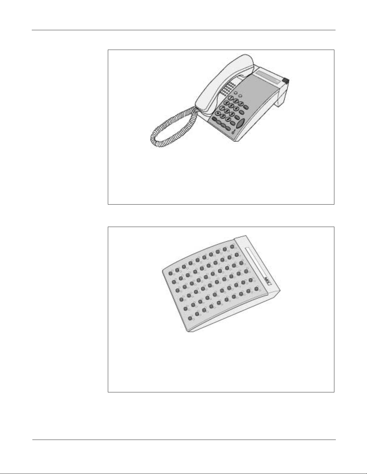
Chapter 3 Terminals D
This digital termin al has 2 F lexible li ne/Fea ture Acc ess keys, 8 dedica ted
Function Keys, Handsfree Speakerphone Operation (Half Duplex), Large
Call/Message indicator and optional Wall Mount Unit (730112). This
terminal has no built-in LLA.
term
Series E
This terminal comes in Whi te (W H) onl y.
Figure 3-15 DTP-2DT-1 (WH) TEL
This Console is equipped with 60 programmable line keys (each with a
two-color LED). These keys can be programmed as Direct Station keys,
function keys, or outside line keys. It in terfaces to the NEAX1000 system via
existing 4DLC cards and the new 8DLCH card and uses single pair cabling.
NEAX2000 IVS2 General Description
NDA-24293, Issue 2
This console comes in tw o colors : Bl ack (BK) and Ivory White (WH).
Figure 3-16 DCU-60-1 Console
Page 29
Page 54

term
D
Series E Chapter 3 Terminals
Line Conditions of
Each D
term
The cable length between the DLC card and terminal varies depending on the type of
terminal. This table shows the line conditions of each D
Series E Terminal
Table 3-2 Line Conditions of Each D
TERMINAL TYPE CARD TYPE
term
D
Series E
(8 button)
term
Series E
D
(16 button)
term
Series E
D
(32 button)
PN-8DLCL/8DLCP
(STANDARD)
PN-4DLCM/4DLCQ
(STANDARD)
PN-2DLCB/2DLCN
(LONG)
PN-8DLCL/8DLCP
(STANDARD)
PN-4DLCM/4DLCQ
(STANDARD)
PN-2DLCB/2DLCN
(LONG)
PN-8DLCL/8DLCP
(STANDARD)
term
Series E Terminal
CABLE LENGTH*
(CABLE 0.5φφφφ/24 AWG)
984 ft. (300 m)
984 ft. (300 m)
[3937 ft. (1200 m)]
2788 ft. (850 m)
[3937 ft. (1200 m)]
656 ft. (200 m)
656 ft. (200 m)
[3937 ft. (1200 m)]
2788 ft. (850 m)
[3937 ft. (1200 m)]
656 ft. (200 m)
term
and DSS/BLF Console.
REMARKS
Note 1
Note 1
Note 1
DSS/BLF Console
Note 2
PN-4DLCM/4DLCQ
(STANDARD)
PN-2DLCB/2DLCN
(LONG)
PN-8DLCL/8DLCP
(STANDARD)
PN-4DLCM/4DLCQ
656 ft. (200 m)
[3937 ft. (1200 m)]
2788 ft. (850 m)
[3937 ft. (1200 m)]
984 ft. (300 m)
984 ft. (300 m)
(STANDARD)
PN-2DLCB/2DLCN
2788 ft. (850 m)
(LONG)
*The value in brackets [ ] shows the cable length when local power is supplied.
Note 1:
When using PN-8DLCL or PN-8DLCP card, the long line function is not available, even if D
equipped with Long Line Adapter.
Note 2:
The DSS/BLF Console requires local AC/DC power supply.
Note 1
term
is
Page 30
NEAX2000 IVS2 General Description
NDA-24293, Issue 2
Page 55

Chapter 3 Terminals SN716 DESKCON
SN716 DESKCON
The SN716 Desk Console has an ergonomic desig n and provides full ac cess to all
PBX Console features. It connects to the NEAX2000 IVS
cards as the D
term
Series E and Series III terminals. The SN716 Desk Console has
2
using the same circuit
ATT Interface (ATI) to connect to the PBX. This interface is 6-core Modular Jack;
inner 1 pair for signal and outer 2 pairs are for power supply.
The SN716 Desk Console operates on a switched-loop basis with a maximum of 6
Attendant loop s termina ting at each console on the asso ciated Inte rface card. The
Attendant uses these loops for answering, originating, holding, extending, and
reentering calls. When Attendant loop release is used, the number of loops is
effectively increased to a maximum of 12 for each console.
2
The NEAX2000 IVS
supports a maximum of eight SN716 DESK Consoles.
NEAX2000 IVS2 General Description
NDA-24293, Issue 2
Figure 3-17 SN716 DESKCON
Page 31
Page 56

SN716 DESKCON Chapter 3 Terminals
SN716 DESKCON Features
Line Conditions of the SN716 DESKCON
• Character LCD (4x40 characters)
• LCD designation strips
• Software-controlled LCD loop key
• Full access to PBX features
• Headset connectivity
• Recorder connectivity
The cable length between the DLC card and terminal varies depending on the type of
terminal. Table 3-1 shows the line conditions of the Attendant Console.
Table 3-1 Line Conditions of the SN716 DESKCON
CABLE LENGTH*
TERMINAL TYPE CARD TYPE
SN716
DESKCON
PN-8DLCL/8DLCP And
PN-PW00 or AC Adapter
PN-4DLCM/4DLCQ and
PN-PW00 or AC Adapter
(CABLE 0.5φφφφ/24
AWG)
1000 ft. (304 m)
1500 ft. (457 m)
REMARKS
Page 32
NEAX2000 IVS2 General Description
NDA-24293, Issue 2
Page 57

Chapter 4 Equipment Description
Modules
EQUIPMENT NAME FUNCTIONAL NAME FUNCTION
IVS VS PIMF (UA) PIM Port Interface Module (PIM)
ICS VS BASE (UA) BASE/TOP ASSEM Base/Top Cover Assembly
ICS VS BATT (UA)
Installation Hardware
EQUIPMENT NAME FUNCTION
HANGER ASSEM (B) Wall Hanger Assembly
MOUNTING BRACKET Safety Mounting Bracket
19" RACK BRACKET (A) 19-inch Rack Mounting Bracket Type A
19" RACK BRACKET (B) 19-inch Rack Mounting Bracket Type B
I/F BRACKET ASSEM Inter Frame Bracket Assembly
BASE TRAY ASSEM Base Tray Assembly
Common Control
EQUIPMENT NAME FUNCTIONAL NAME FUNCTION
PN-CP14
BATTM
MP
Battery Module for housing PIM
or CS (ZT) backup batteries
Main Processor & BUS interface
for PIM 0 to PIM 1
PN-CP15
PZ-M537
PN-PW00 EXTPWR Power Supply card for DESKCON
PZ-PW121 AC/DC PWR Main Power Supply card
PZ-PW122
NEAX2000 IVS2 General Description
NDA-24293, Issue 2
FP
EXPMEM
DC/DC PWR
Firmware Processor & BUS
interface for PI M Expansion
Memory Expansion Card for
MP/AP00 Card
Power Supply card for Cell Sta tion
(Zone Transceiver)
Page 33
Page 58

Analog C.O. Trunk Chapter 4 Equipment Description
Analog C.O. Trunk
Analog DID Trunk
EQUIPMENT
NAME
FUNCTIONAL
NAME
FUNCTION
PN-4COTB COT 4-line Central Office Trunk Card (Ground Sta rt
Trunk)
PN-4COTG COT 4-line Cen tra l Office Trunk C ard (Loop Start
trunk)
PN-8COTS COT 8-line Cen tral Office Trunk Card (Ground Start
Trunk)
PN-8COTQ COT 8-line Cen tra l Office Trunk C ard (Loop Start
Trunk)
EQUIPMENT
NAME
FUNCTIONAL
NAME
FUNCTION
PN-AUCA AUC 2-line Analog Long Line Circuit Card provided
with Power Failure Transfer (PFT) Function, or
2-line Dire ct Inward Dial in g Trunk Card
PN-4DITB DIT 4-line Direct Inward Dialing Trunk Card
Analog Tie Line Trunk
EQUIPMENT
NAME
PN-2ODTA ODT 2-line Out Band Dialing Trunk Card
Analog Station
EQUIPMENT
NAME
PN-4LCD-A LC 4-Line Analog Line Circuit Ca rd for Single Line
PN-8LCAA LC 8-lin e Analog Line Cir cuit Card for Single Line
PN-AUCA AUC 2-line Analog Long Line Circuit Card provided
FUNCTIONAL
NAME
FUNCTIONAL
NAME
FUNCTION
FUNCTION
Telephones
Telephones
with Power Failure Transfer (PFT) Function, or
2-line Dire ct Inward Dial in g Trunk Card
Page 34
NEAX2000 IVS2 General Description
NDA-24293, Issue 2
Page 59

Chapter 4 Equipment Descrip t io n Di gi tal Sta tio n
Digital Station
Digital Trunk
EQUIPMENT
NAME
PN-2DLCB/
PN-2DLCN
FUNCTIONAL
NAME
FUNCTION
DLC 2-line Digital Long Line Circuit Card for
term
D
Series E/III, Elite, Electr a Pro,
DSS Console, DESKCON
PN-4DLCM DLC 4-line Digital Line Circuit Car d fo r
term
Series E/III, Elite, Electra Pro,
D
DSS Console, DESKCON
PN-4DLCQ DLC 4-line Digital Line Circuit Card for
term
D
Series E/III, DSS Console, DESKCON
PN-8DLCP DLC 8-line Digital Line Circuit Card for
term
D
Series E/III, DSS Console, DESKCON
EQUIPMENT
NAME
FUNCTIONAL
NAME
FUNCTION
PN-24DTA-C DTI Digital Trunk I nterface (23B+D, 1.5 Mbps) Card
(T1)
PN-30DTC-A DTI Digital Trunk Interface (2 Mbps) Card (E1)
Data
CCIS
EQUIPMENT
NAME
FUNCTIONAL
NAME
FUNCTION
PN-2DPCB DPC 2-line Data Port Controller Card for 48K,
64 Kbps, V110, V11
SPN-V35 ADP V.35 Data Terminal Equipment Interface Card
EQUIPMENT
NAME
FUNCTIONAL
NAME
FUNCTION
PN-24DTA-C DTI Digital Trunk Interfa ce (23B+D, 1.5 Mbps) Card
(T1)
PN-SC00 CCH Common Channel Handler Card
PN-30DTC-A DTI Digital Trunk Interface (2 Mbps) Card (E1)
NEAX2000 IVS2 General Description
NDA-24293, Issue 2
Page 35
Page 60

ISDN/ECCIS Chapter 4 Equipment Description
ISDN/ECCIS
IP Trunk
EQUIPMENT
NAME
FUNCTIONAL
NAME
FUNCTION
PN-BRTA BRT 1-line Basic Rate (2B+D) Interface Trunk card
PN-2BRTC BRT 2-line Bas ic Rate (2B+D) Int erface Trunk card
PN-2ILCA ILC 2-line BRI Station card
PN-SC03
PN-24DTA-C
PN-24PRTA
8ICH
DTI
PRT
BRI (station), one 8ICH needed for every four
2ILCA cards
Digital Trunk Interface (23B+D, 1 . 5Mbps)
Card (T1)
ISDN Primary Rate (23B+D) I nterface Card
(Built-in D-Channel)
PN-SC01 DCH D-channel Hand ler Card
SPN-SC01 QSIG QSIG Protocol Handler
EQUIPMENT
NAME
FUNCTIONAL
NAME
FUNCTION
PN-IPTA IPT IP Trunk Interface card (16 ch)
Registers
PN-4VCTH VCT 4-channel CODEC Card for IP Trunk
EQUIPMENT
NAME
FUNCTIONAL
NAME
FUNCTION
PN-8RSTA PBR 8-line PB Receiver Card
PN-4RSTB
MFR
4-line MF Receiver, MFC Receiver/Sender
Card
PN-4RSTC CIR 4-line Caller ID Receiver Trunk Card
PN-4RSTB-911 MFR 4-line Register Sender for 911
Page 36
NEAX2000 IVS2 General Description
NDA-24293, Issue 2
Page 61

Chapter 4 Equipment Desc ription Miscellaneous Trunk
Miscellaneous Trunk
EQUIPMENT
NAME
PN-DK00 DK 8-circuit External Relay Control/External Key
PN-CFTA CFT 6/10 Party Conference Trunk Card
PN-CFTB CFT 6 Party Conference Trunk Card
PN-2DATA DAT 2-line Digital Announcement Trunk Card
PN-4DATC DAT 4-line Digital Announcement Trunk Card
PZ-8PFTB PFT 8-line Power Failure Transfer Card
PN-TNTA TNT 2-line T o ne/Music Source Interface C ard
PN-2AMPA AMP 2-line Amplifier Trunk Card
PN-CFTB CFT 6/10 Party Conference Trunk Card
System I/O, OAI, ACD
EQUIPMENT
NAME
PN-AP00-B MRC Provides four RS-232C ports, and is used for
FUNCTIONAL
NAME
FUNCTIONAL
NAME
FUNCTION
Scan Card
FUNCTION
SMDR, Hotel Printer, CIS, PMS, MCI, CS report
functions.
Voice Mail
SPN-AP01 IP Provides one RS-232C port and one Ethernet
interface port. Used for O A I f unction, ID code
expansion.
PN-CC01 ETHER Ethernet Control Card
EQUIPMENT
NAME
FUNCTIONAL
NAME
FUNCTION
PZ-VM00-M VM 4-port Voice Mail Card (NEAXMail AD-8)
PZ-VM01 VM 4-port Voice Mail Extension Card
NEAX2000 IVS2 General Description
NDA-24293, Issue 2
Page 37
Page 62

Wireless Chapter 4 Equipment Desc ription
Wireless
Remote PIM
EQUIPMENT
NAME
FUNCTIONAL
NAME
FUNCTION
PN-2CSIA CSI 2-line Zone Transceiver Interface Card
PN-SC03-A CSH CS (ZT) Handler Card
PN-AP00-A DBM Da ta Base Module Card for WCS Roaming
function One card per WCS system.
SPN-SC01 DCH-Q Q931 Protocol Handler for Wireless Roaming
EQUIPMENT
NAME
FUNCTIONAL
NAME
FUNCTION
PN-DAIA DAI Digital Trunk Interface (23B+D, 1.5Mbps) Card
for Remote PIM
PN-DAIB DAI Digital Trunk Interface (23B+D, 1.5Mbps) Card
for Remote PIM
PN-DAIC DAI Digital Trunk Interface (23B+D, 1.5Mbps)
Channel Expansion Card for Remote PIM
PN-DAID* DAI Digital Trunk Interface (2Mbps) Card for Remote
PIM
Optical Interface
PN-DAIE* DAI Digital Trunk Interface (2Mbps) Card for Remote
PIM
PN-DAIF* DAI Digital Trunk Interface (2Mbps) Channel
Expansion Card
*These cards a re subject to availability.
EQUIPMENT
NAME
FUNCTIONAL
NAME
FUNCTION
PN-M10 M10 Optical Interface Card
Provides internal optical modem to T1/E1
network or Remote PIM
Page 38
NEAX2000 IVS2 General Description
NDA-24293, Issue 2
Page 63

Chapter 5 Feature Description
Account Code
This feature, when used with Station Message Detail Recording (SMDR), allows
station users and Attendants to enter a cost accounting or client billing code (up to 16
digits) into the system.
Add-On Module
This feature allows the Add-On Module to be combined with a Multiline Terminal
when there are insufficient line or trunk keys provided at the Multiline Terminal.
When the EDW-48-2 unit keys are programmed as line/trunk keys, the additional 25
lines/trunks and the existing lines/trunks set for the Multiline Terminal can be
accessed directly (maximum of 49 lines/trunks). The station speed dialing function
can be assigned for all keys on the EDW-48-2 unit. Also, one of the last 3 keys can be
used as a Day/Night change key.
Alarm Indications
Faults are indicate d by the Major/Mino r (MJ/MN) lamps loca ted on the AC/DC
Power Supply and, optionally, an external alarm display unit. Station Application not
applicable.
Alphanumeric Display
The ETJ-16DC-1 Multiline Term inals are each equipp ed with a 2-l ine, 20- character
Liquid Crystal Display (LCD). These displays are used to provide alphanum eric
information including clock/calendar and call processing information.
Station Application All Multiline Term inals with an LCD display.
Analog Port Adapter
This feature allows an APR-J or APA-J unit com bined with a Multiline Termin al to
connect to an analog terminal such as an analog telephone, Modem, and PC with
built-in Modem. There are two communication modes for the terminal connected via
the Analog Port Adapter as shown below:
1. Single Port Mode
A Multiline Termin al and an a nalog term inal sha re the sam e port. In th is mode,
the Multiline Te rminal and the analog terminal ca nnot be used simu ltaneously.
2. Dual Port Mode
NEAX2000 IVS2 General Description
NDA-24293, Issue 2
A Multiline Terminal and an analog terminal use different ports. In this mode, the
Multiline Terminal and the analog terminal can be used simultaneously.
Page 39
Page 64

Announcement Service Chapter 5 Feature Description
Announcement Service
This feature allows station users to record messages on Digital Announcement Trunk
(DAT) cards. When a station user dials the feature access code for this feature, the
user receives the corresponding message from the system.
Answer Key
An Answer Key is provided on all Multiline Terminals. The Answer Key can be used
to answer incoming calls on out side li nes, and primar y or secon dary ext ension s. When
the Answer K ey is use d to answ er an in coming call with a call in progr ess, the first
party is placed on hold and the second party is connected. If the Answer Key is
depressed while in a three-party call, the user can alternate between each party and a
Broker's Call is established.
Attendant Assisted Calling
This feature allows a station user to ask an Attendant for assistance in originating a
call. Three methods are available: non-de lay, delay, and passing dial tone.
Attendant Camp-on
This feature perm its the Attendan t to hold a n incoming call in a s pecial mo de when
the desired station for the trans fer is bus y. The Attendant sends a Camp-On tone to the
busy station. When that s tation becomes idle, it is aut omat ically alerted and conne cte d
to the waiti n g party.
Attendant Console
SN716 DESKCON
Attendant Called/Calling Name Display
The Attendant Console (SN716 DESKCON) operates on a switched-loop basis with a
maximum of 6 Attendant loops terminating at each console on the associated Interface
card. The Attendant uses th ese loops for answ ering, originating, holding, ex tending,
and reentering calls. When Attendant loop release is used, the number of loops is
effectively increased to a maximum of 12 for each console.
This feature provides a display of the callin g/called party's name o n the Atte ndant
Console LCD for Attendant Called/Calling Name Display. On attendant-to-station
calls, the LCD display the name assigned to the primary extension of the station. On
attendant-to-trunk calls, the LCD displays the name assigned to the trunk route of the
trunk.
Page 40
NEAX2000 IVS2 General Description
NDA-24293, Issue 2
Page 65

Chapter 5 Feature Description Attendant Console
Attendant Called/Calling Number
Attendant Call Selection
Attendant Console
Lockout Password
Attendant Do Not Disturb Setup And Cancel
Attendant Interposition Calling/Transfer
This feature provides a di splay of the s tation number and station n ame on the
Attendant Console during an Attendant-to-station connection. During an
Attendant-to-trunk connection, the same display shows the trunk route designation
and a trunk identification code (4 digits).
This feature allows assignmen t of keys on the Atte ndant Consol e to particu lar type s of
trunk routes (such as WATS or FX) and particular types of service calls (such as
Attendant recal ls, inte rcept call s, etc.). LEDs in dicate t he type of incomin g call a nd
pressing the associated key allows the Attendant to answer the calls in any order.
This feature allows the Attendant Console to be set into a lockout mode. This disables
the console from orig inati ng or re ceivi ng ca lls and setting or reset ting s erv ice fe ature s.
To return the Console to its manual operating condition a password is required.
The Attendant has the ability to enter and remove individual stations from Do Not
Disturb (DND). Additionally, the Attendant can set one preassigned group of stations
into, or out of, Do Not Disturb.
This feature allows any Attendant to directly converse with another Attendant and
also allows Attendants to transfer calls from their console to another Attendant's
console in systems where Multiple Console Operation has been provided.
Attendant Lamp Check
Attendant Listed Directory Number
Attendant Loop Release
Attendant Programming
Attendant Training Jacks
Audible Indication Control
This function is used to check the status of keys, lamps, and LCDs mounted on the
Attendant Console to verify that various operations of the Attendant Console are
functioning normally. The check is done by a preset procedure.
This feature provides a display of the Listed Directory Number on the Attendant
Console when the operator has answered a Listed Directory Number call.
This feature allows an Attendant Console loop to become available for a second call
as soon as the Attendant has directed the first call to a station, even if that station does
not answer.
This function is allo wed only for the Attendant Con sole (SN610) an d is used to
execute DISA code set up, speed dial programming, and system clock set up
operations.
The Attendant Console can be equipped with two headset/handset jacks using an
optional adapter. Two jacks are equipped on the adapter and can be used for training
new operators.
This feature allows the Attendant to adjust the volume of audible indications received
at the Attendant Console.
NEAX2000 IVS2 General Description
NDA-24293, Issue 2
Page 41
Page 66

Attendant Console Chapter 5 Feature Description
Call Processing Indication
Call Queuing
Call Splitting
Call Waiting Display
Common Route Indial
This feature provides visual indications of all calls being processed or awaiting
processing at the Attendant Console.
This feature provides the Attendant the ability to handle a series of exchange network
calls in the order of their arrival, (first in, first ou t) thereby eli minatin g unnecess ary
delays.
This feature allows the Attendant to confer privately with one party on an Attendant
handled connection without the other party overhearing.
This feature provides a visual indication to the Attendant when one or more calls are
waiting to be answered.
This feature allows assignment of incoming DID calls to different Attendant Call
Selection keys based on the last 4 digits dialed into the system. Up to eight individual
Listed Directory Numbers can be assigned in system programming. When an
incoming call to any of these trunks is received, an Attendant Call Selection key will
flash and the LCD display will indicate the Listed Directory Number associated with
that trunk route.
Dialed Number Identification Service (DNIS)
Incoming Call Identification
Individual Trunk Access
Multi-Function Key
Multiple Console Operation
This feature provides a display of the company name on the Attendant Console when
the Attendant has answered a Listed Directory Number or a Tie Line call.
Incoming calls are identified by various mean s. Refer to Attendant Called/Callin g
Number, Attendant Ca ll Selection, A ttendant So u rce Key, At tendant Liste d Directory
Number and Common Route Indial Features and Specifications.
The Attendant Conso le is pro vided with th e abil ity to acc ess ea ch indi vidual trunk by
dialing an associated identification code. This allows detection of faulty trunks during
regular testing or after complaints. The Customer Administration Terminal (CAT) or
Maintenance Administration Terminal (MAT) has the capability to then busy out the
trunk until repair is made.
This feature allows the top row of keys on the Attendant Console to perform and
display multiple functions in accordance with the status of call processing.
This feature allows more than one Attendant Console to operate within the same
system.
Page 42
NEAX2000 IVS2 General Description
NDA-24293, Issue 2
Page 67

Chapter 5 Feature Description Attendant Delay Announcement
Pushbutton Calling - Attendant Only
Serial Call
Time Display
Trunk Group Busy Display
Unsupervised Trunk-to-Trunk Transfer By Attendant
This feature permi ts an operat or to plac e all calls over Dual- Tone, Mul ti-Frequen cy
(DTMF) lines from the pushbutton keypad on the Attendant Console.
This feature is acti vated by the Attendant when an incoming calling party wishes t o
speak with more than one internal party. When th e internal station subsequently
disconnects from the Cen tral Office line c all, the Central O ffice party a utomatically
rings back to the same Attendant.
This feature provides a digital time display on the Attendant Conso le (SN610) LCD.
A visual indication is supplied to the Attendant w hen all trunks in a particular tru nk
group are busy.
This feature allows a n Attendant to transfer an in comi ng or outgoing call on one trunk
to an outgoing trunk and exit the connection before the called party answers.
Attendant Delay Announcement
This feature provides an announcement, via a Digital Announcement Trunk Card, to
external calls that are not answered by the attendant within a predetermined time.
Attendant Lockout
This feature denies an Attendant the ability to reenter an established trunk or station
connection witho ut being rec alled by that station after th e call is pu t in consul tation
hold.
Attendant Overflow
When an incomi ng call, w hich has termina ted from a trunk to th e Attend ant Con sole,
remains unanswered after a predetermined time period, this feature provides a change
to Night Service for that partic ular trunk.
Attendant Override
This feature permits an Attendant to enter a busy conn ection (station or trunk) using
the Attendant Console. When this feature is activated, a warning tone is sent to the
connected parties after which , they are c onnected w ith the At tendant in a three- way
bridge.
NEAX2000 IVS2 General Description
NDA-24293, Issue 2
Page 43
Page 68

Authorization Code Chapter 5 Feature Description
Authorization Code
An Authorization Code is a numerical code which will temporarily change a station’s
Class of Service to a Class of Service assigned to that Authorization Code. This new
Class of Service allows access to trunks, dialing pattern s, and/or features that w ould
otherwise be restricted.
Automated Attendant
This feature allows the system to answer incoming trunk calls. The system will supply
a message and/or dial tone to the caller. The caller can then dial the desired extension
number and be directed to that station.
Automatic Call Distribution (ACD)
The Automatic Call Distr ib u ti on ( ACD) f eature permits incomin g calls to terminate to
a prearranged group of stations. Calls are distributed in the ord er of arrival to idle
terminals within the group, based on which terminal has been idle the longest period
of time. Stations may log on/log off from the ACD group. Supervisor stations may
monitor conversations of agents.
Busy In/Busy Out ACD
Call Waiting Indication - ACD
Delay
Announcement ACD
Hunt Past No Answer - ACD
Immediate Overflow - ACD
This feature allows an agent in an ACD group to log their station onto or off of the
group. This allows the system to control whether a call directed to the pilot number of
the ACD group goes to that station or not. This prevents incoming calls from being
directed to stations at which no agent is available.
This feature provides a visual ind ication when an incoming call to an ACD group is
placed in queue , due to an “all a gents bu sy” co ndition. On exte rnal rel ay contro lled
indicator or an LED on a Multi line Termin al can be use d to provid e Call Waiting
Indication.
This feature allows the system to provide a recorded announcement to an incoming
caller placed in queue to an ACD group. A single announcement, or two separate
announcements, can be provided.
This feature allows calls targeted at an ACD group to hunt past an agent’s station,
after a no answer condition, if the agent forgets to log off of the group and the agent is
unable (or not available) to answer the call.
This feature allows a call directed to an ACD group to immediately overflow to
another ACD group, upon encountering an “all agents busy” condition.
Priority Queuing ACD
Page 44
This feature allows the system to prioritize incoming calls by trunk route and on a per
station basis, when the call enters an ACD queue. When a call is considered as a
priority, it is placed at the beginning of the queue.
NEAX2000 IVS2 General Description
NDA-24293, Issue 2
Page 69

Chapter 5 Feature Description Automatic Call Distri bution wit h Manag eme nt Inform ati on Sy st em (MI S)
Queue Size Control - ACD
Silent Monitor ACD
On incoming DID/Tie line calls, the system can be assigned a threshold which limits
the number of calls in queue. When the queue size threshold is exceeded, incoming
callers are connected to busy tone.
This feature provides the ACD group super visor with th e abili ty to moni tor a c all to an
ACD agent. The silent monitor function gives no indication (as an option) to either the
agent or the calling party.
Automatic Call Distribution with Management Information System (MIS)
The Automatic Call Distribution (ACD) with Management Information System (MIS)
feature provides a management information system to be used in conjunction with the
built-in ACD features of the system. The MIS incorporates a supervisor's terminal for
real-time monitoring of agent activity, amber and red alarms, and hard-copy summary
reports.
Automatic Camp-on
An incoming Direct Inward Termination (DIT) call which has been terminated to a
busy station can be C amped- On a utomatic ally. W hen the busy statio n becomes idl e,
the station is automatically called and connected to the camped on incoming trunk
call.
Automatic Number Identification (ANI)
This feature receives the calling subscriber's number automatically sent from T1
network using MF signaling and d isplays the callin g number on the LCD of a
Multiline Terminal and an Attendant Console.
Automatic Recall
This feature work s as a tim ed remind er. W hen a call re mains on H old, Ca mp-On or
ringing unanswered for a fixed interval after being transferred, the station that initiated
the hold, transfer , or Camp-On is a utomatically al erted. Statio n Application Al l
stations.
Automatic Wake-up
This featur e allows the sy st e m to be p ro grammed to automatically call guest rooms or
administration stations at specified times. Upon answering, the guest is connected to a
recorded announcement or music source. A printout of unanswered or blocked
Automatic Wake-Up attempts for each guest room is provided using the Hotel/Motel
printer.
NEAX2000 IVS2 General Description
NDA-24293, Issue 2
Page 45
Page 70

Background Music Chapter 5 Feature Description
Background Music
Background Music can be provided on a dial-up basis over Multiline Terminal
speakers. Incoming voice announcements, ringing and recalls override Background
Music. Up to 10 music programs can be offered.
Boss / Secretary Calling
A secretary with a Multiline Terminal can use an appearance of the boss' extension to
screen calls for that extension, and announce and/or transfer calls to that extension.
Additionally, th e secretary ca n call the bos s during a busy condition an d send a
Message Waiting Indication to the boss' station.
Broker's Call
This feature a llows a Multili ne Ter minal or Single Line Te lephon e user to alter nate
between two parties, talking to one party while the othe r par t y remai ns on Hold on the
same line. The Multiline Terminal user uses the TRF or ANS key to alternate between
the two parties. The Single Line Telepho ne user uses the Hold featur e to alternate
between the two parties.
Call Back
Call Forwarding
This feature allows a calling party to set an automatic Call Back when a busy or no
answer condition is encountered. When the busy station becomes idle, the station that
set the Call Back will be called. In case of Call Back no answer, the Call Back to the
setting station is initiated immediately after the called station goes on hook after
making a call or accessing a feature.
Call Forwarding allows calls di rected to a station t o be rou ted to ano ther stat ion, an
Attendant, an outside number or voice mail equipment. The types of Call Forwarding
provided are:
• Call Forwarding - All Calls
• Call Forwarding - Busy Line
• Call Forwarding - No Answer
• Call Forwarding - Destination
• Multiple Call Forwarding - All Calls
• Multiple Call Forwarding - Busy Line
• Multiple Call Forwarding - No Answer
• Split Call Forwarding - All Calls
• Split Call Forwarding - Busy Line
• Split Call Forwarding - No Answer
• Attendant Call Forwarding Setup and Cancel
• Call Forwarding - Override
• Group Diversion
Page 46
NEAX2000 IVS2 General Description
NDA-24293, Issue 2
Page 71

Chapter 5 Feature Description Call Forwarding
Attendant Call Forwarding Set-up and Cancel
Call Forwarding All Calls
Call Forwarding Busy Line
Call Forwarding No Answer
All of the various types of Call Forwarding can be set up or canceled from both
Attendant Consoles.
This feature al lows all calls directed t o a particular extensio n to be rerout ed to an
alternate destination, regardless of the busy or idle status of the extension. Call
Forwarding - All Calls can be set by an Att endant Console, the indiv idual station user,
a Multiline Terminal with a secondary appearance of the sta tion's extension, or from
another station (which can program itself to be the destination of the rerouting).
This feature permits a call to a busy extension to be routed to a pre-designated station,
Attendant Console, or voice mail equipment. Call Forwarding - Busy Line can be set
or canceled by an Attendant Console, the individual station user, or a Multiline
Terminal with a secondary appe arance of the station's extension.
This feature reroutes calls to extensions which do not answer. These calls can be
rerouted to another station, an Attendant Console or voi ce mail equipment. C all
Forwarding - No A nswer can be se t by the individua l station user, an A ttendant
Console, or by a Multiline Terminal with a secondary appearance of the station's
extension.
Call Forwarding Destination
Multiple Call Forwarding - All Calls
Multiple Call Forwarding - Busy Line
Multiple Call Forwarding - No Answer
Split Call Forwarding - All Calls
This feature allows a station (A) user to set Call Forwarding - All Calls from another
station (B) w ithin the syste m , to the user's station (A).
When a forwarded call is rerouted to a station that has also set a Call Forward, the call
can be forwarded to another station. A call can be forwarded up to a maximum of five
times, as specified in system programming.
This feature permits a call to a busy station to be forwarded, multiple times, to a
pre-designated idle station.
This feature permits a ca ll to an unanswered station, the ability to be fo rwarded
multiple times to a pre-designated station that does not have Call Forwarding - No
Answer set or to the Att endant Console.
This featu re allo ws al l in ter na l an d ex ter na l c all s t o a bus y exte n si on t o be reroute d to
different de stinations in dividually, re gardless of t he busy or idle status of the
extension.
Split Call Forwarding - Busy Line
NEAX2000 IVS2 General Description
NDA-24293, Issue 2
This feature allows internal and external calls to a busy extension to be rerouted to
separate destinations. Destinations may be an internal station, A ttendant Console, or
voice mail.
Page 47
Page 72

Call Park Chapter 5 Feature Description
Split Call Forwarding - No Answer
Call Forwarding Override
Group Diversion
Call Park
Call Park - System
Call Park - Tenant
This feature allows internal and external calls, to extensions that do not answer, to be
rerouted to separate destinations individually.
This feature allows the call forward destination station to call the station which set call
forward. The call forward setting will be ignored.
This feature allows all calls terminated to an extension that are not answered within a
predetermined time to be forwarded to a pre-designated station.
This feature enables a station user or attendant to place a call into pre-designated Call
Park locations. The station user or attendant is then free to process other calls. This
feature is available system wide and for individu al tenants.
When a call is parked by Call Park-System, the call can be retrieved from Call Park by
any station in the system.
When a call is parked by Call Park - Tenant, the cal l can be retrieved from Call
Park-Tenant by any station within the t enant from which the call was origina lly
parked.
Call Pickup
Call Pickup - Direct
Call Pickup Group
Call Pickup Designated Group
This feature enables a station user to answer any call directed to another station, to a
station within the user's own Call Pickup Group, or to a station within a different Call
Pickup Group. Three Call Pickup methods are available: Call Pickup - Direct, Call
Pickup - Group, and Call Pickup - Designated Group.
This method permits a station user to pickup a call to any other station in the system
by dialing a specific Cal l Pickup feature access code and the number of the called
extension.
This method permits a station user to answer any calls directed to other extensions in
their preset pickup group by dialing a Call Pickup - Group featu re access code.
This method permit s a station user to answer an inco ming call direc ted to another
group by dialing the Call Pick-up - Designated Group feature access code and any
station within the group to which the ringing station belongs.
Page 48
NEAX2000 IVS2 General Description
NDA-24293, Issue 2
Page 73

Chapter 5 Feature Description Call Redirect
Call Redirect
Without answering incoming calls or held calls that terminate to the line keys of a
Multiline Term in al, the ca lls can be tr ansfe rre d to a p re-pr ogr amm ed st ation or Voice
Mail System. Two transferring destination number can be designated per tenant, in
system data programming. This feature can be used together with the Caller ID
Display feature.
Call Transfer
This feature permits a station user to transfer a call to another station in the system
directly, or with assi sta nce from the attendant.
Call Transfer All Calls
Call Transfer Attendant
Caller ID Class
Caller ID Display
This feature permits a station user to transfer incoming or outgoing calls to another
station within the system without attendant assistance.
This feature permi ts a statio n user, wh ile connec ted to an internal or outs ide call, to
signal the Attendant and have the Attendant transfer the call to another station within
the system or to an outside connection.
This feature receives the calling subscriber’s name and numbe r sent from a public
network using a MODEM signal and displays the name or number on an LCD of a
Multiline Terminal and Attendant Console.
Without answering incoming calls or held calls which terminate to the line keys of a
Multiline Terminal, the calling party's information can be confirmed by the
indications on the LCD. The following information is indicated according to the kind
of the calls.
Camp-on
This feature provides selected stations or outside calls with Camp-On capability to a
busy internal station. Two Camp-On metho ds are provided. The call waiting method
allows a station or an outside party to camp itself on to a busy station. The transfer
method allows a transferred outside call to be camped-on to a busy station.
Centrex Compatibility
A combination of features allows full integration of the NEAX2000 IVS2 with
Centrex service.
NEAX2000 IVS2 General Description
NDA-24293, Issue 2
Page 49
Page 74

Check In / Check Out Chapter 5 Feature Description
Check In / Check Out
When this featu re is activated, th e following op e rations occur:
• Check In
• Room C ut off is clea red .
• Check Out
• Room Status printout is supplied.
• Do Not Disturb is reset.
• Room C ut o ff is set.
• Message Waiting is reset.
• Automatic Wake Up is cleared.
Class of Service
This feature permits all stations to be assigned a Class of Service in accordance with
the degree of system use desir ed. The Class of Service is used to assi gn rest rict ions fo r
trunk access and feature access.
Code Restriction
This feature allows the NEAX2000 IVS2 to be programmed to restrict outgoing calls
according to specific area and/or Central Office codes. This restriction is controlled on
the basis of a three-digit area code or six-digit area and office code numbering plan.
Conference (Three/Four Party)
This feature provid es a station user the ability to add-on another party (trunk or
station) to a call already in progress. Si ngle Line Telephon e users can add up to one
additional party and Multiline Terminal users can add up to two additional parties.
Conference (Six/Ten Party)
This feature permits a station user or Attendant (conference leader) to establish a
Conference among as many as six or ten parties (including the Conference leader).
Consecutive Speed Dialing
For Speed Dialing, all digits are registered as a Speed Dialing Code. In the case of
Consecutive Speed Dialing, the common portion of the number is registered as a
speed calling code, and the remaining digits of each number are dialed by each
individual calling station or by using a Station Speed Dial key on a Multiline
Terminal.
Page 50
NEAX2000 IVS2 General Description
NDA-24293, Issue 2
Page 75

Chapter 5 Feature Description Consultation Hold
Consultat ion Hold
This feature permits a station user to hold any incoming or outgoing CO call, tie line
call, or any intra-office call while originating a call to another station user within the
system.
Customer Administration Terminal (CAT)
In additio n to t he M ain tena nce Adm ini stra tion Te rmin al (M AT ), pr ogr ammi ng o f th e
NEAX2000 IVS
designated Multiline Terminals can be placed in program mode, and system data can
then be changed. To prevent unauthorized changes, password levels are assigned,
providing authorizatio n for access to certain areas of programming and denying
access to others.
Data Line Security
This feature allows line circuits that are used for data transmission to be protected
from interruptions such as Attendant Camp-On, Executive Override, and Attendant
Override.
Delayed Ringing
This feature enables trunks and station lines to ring immediately at the terminating
station, but also, after a programmable period of time has elapsed, to ring at secondary
Multiline Terminals with that trunk or line appearance.
Diagnostics
2
can be done from selected Multiline Terminals with LCD. The
To assist maintenance personnel, the NEA X2000 IVS2 provides diagnostic
capabilities such as fault code generation, device status information and alarm
information rec ording which ca n be acce ssed fro m the M aintenan ce Admin istrati on
Terminal (MAT) or Customer Administration Terminal (CAT).
Dial By Name
This feature allows a Multilin e Terminal user to search for a desired number by name.
The number and name are regis tered in t he syste m and they are shown on Multiline
Terminal LCD. The Multiline Terminal user ca n search for the desired number by
name using up or down soft keys. When the Multiline Terminal user finds the desired
number, the call can be originated by pressing the Line/Trunk key or going off hook.
Dial Conversion
The system can be assigned to use rotary Dial Pulse (DP) or Dual Tone
Multi-frequency (DTMF) trunks and stations. This feature provides for the repeating
of digits dialed by the station user onto the C.O. t runks.
NEAX2000 IVS2 General Description
NDA-24293, Issue 2
Page 51
Page 76

Direct Data Entry Chapter 5 Feature Description
Direct Data Entry
This feature allows a maid or other hotel personnel to enter numeric data to the
Property Management System (PMS), using the guest room station for entry through
dial operation. The same numerical data can be output to a Hotel /Motel Printer by
system data programming.
Direct Digital Interface
This service feature provides the capability to connect trunks from the NEAX2000
2
IVS
directly to T1 carrier links using either a private or public network.
Direct Inward Dialing (DID)
This feature provides for incoming calls from the exchange network (except FX or
WATS) to reac h any station wi th in the system without attenda n t assistance.
DID Call Waiting
DID Digit Conversion
This feature allows an incoming call on a DID trunk or a tie line to automatically be
Camped-On to the destination station if the destination station is busy.
This feature allows the NEAX2 000 IVS2 to convert the digits received from the
serving C.O. to valid station numbers when the C.O. numbering plan differs from the
desired station numbering plan.
Direct Inward System Access (DISA)
This feature allows an outside caller to access the system using an exchange network
connection without Attendant or station assistance. The outside user may originate
calls over any or all of the system's facilities such as WATS, FX, Tie Line or CCSA.
The outside user can also directly call stations and access miscellaneous trunks for
such features as dictation access.
Direct Inward Termination (DIT)
This feature automati cally routes incoming network exchan ge calls direct ly to a
pre-selected station without Attendant assistance. The call can then be processed by
the called party. Three-party Conference, Call Transfer, etc., are handled in the same
manner as any normal trunk call.
Direct Outward Dialing (DOD)
This feature permits any station user the ability to gain access to the exchange network
by dialing an access code and receiving new dial tone. The user may then proceed to
dial the desired exchange network number.
Page 52
NEAX2000 IVS2 General Description
NDA-24293, Issue 2
Page 77

Chapter 5 Feature Description Direct Station Selection/Busy Lamp Field (DSS/BLF) Console
Direct Station Selection/Busy Lamp Field (DSS/BLF) Console
This feature allows an EDW-48-2A unit associated with a Multiline Terminal to be
used as a Direct Station Selection/Busy Lamp Field (DSS/BLF) Console. When the
buttons on the EDW-48-2A unit are programmed for Direct Station Selection (DSS)
buttons, up to 60 stations can be directly accessed in addition to those already
appearing on the Multiline Terminal. Busy status for e a c h statio n is indi cated b y a red
LED associated with each button. In addition, the DSS console can provide the
following functions:
• Message Waiting - Set/Cancel/Status Display
• Do Not Disturb - Set/Cancel/Status Display
• Automatic Wake Up No Answer - Status Display/Cancel
• Agent Busy Out - UCD - Status Display
• Line Lockout - Status Display
• Room C uto ff - Set/Ca nce l /Sta t us
Busy Out Status Console
Do Not Disturb Console
Message Waiting Console
Room Cutoff Console
This feature allows an EDW-48-2A unit associated with a Multiline Terminal to be
used as a Bu sy Out Stat us Consol e. This feature is activate d by use of a Functio n
Mode key on a DSS/BLF Console. Busy Out Status for each station is indicated by a
red LED associated with each button.
This feature allows an EDW-48-2A unit associated with a Multiline Terminal to be
used as a Do Not Disturb (DND) Console. This feature is activated by the use of a
Function Mode key on a DSS/BLF Console. DND set status for each station is
indicated by a green LED associated with each button. In addition, the Multiline
Terminal user can set/cancel the DND stat us of other sta tions using the DND Console.
This feature allows an EDW-48-2A unit associated with a Multiline Terminal to be
used as a Mess age Wait ing (M W) Con sole. T his feat ure is a ctivated by the use of a
Function Mode key on a DSS/BLF Co nsole. The Message Waiting status for each
station is indicated by a green LED associated with each button. In addition, the
Multiline Terminal user can set/reset MW status using the MW Console.
This feature allows an EDW-48-2A unit associated with a Multiline Terminal to be
used as a Room Cutoff Console. T his feature is activated by the use of a Function
Mode key on a DSS/BL F Console. The Room Cutoff status for each st ation is
indicated by a green LED associated with each button. In addition, the Multiline
Terminal user can set/cancel Room Cuto ff to another station using the R oom Cutoff
Console.
Wake Up No Answer Console
NEAX2000 IVS2 General Description
NDA-24293, Issue 2
This feature allows an EDW-48-2A unit associated with a Multiline Terminal to be
used as a Wake Up No Answer (WU) Console. This feature is activated by a function
mode key on a DSS/BLF Console. The No Answer status for each station is indicated
by a flashing green LED associated with each button.
Page 53
Page 78

Distinctive Ringing Chapter 5 Feature Description
Distinctive Ringing
This feature provid es Dist incti ve Ringin g patte rns to t he st ation so that t he stat ion use r
can distinguish betw een inter nal and ex terna l incomi ng call s. This fe ature also enables
the LED associated with the line key of the Multiline Terminal to flash in two colors
according to the kind of incoming call.
Do Not Disturb
This feature restri cts incoming calls to a station and can be set by an individual s ta tion
or from the Attendant Console . Placing a station in D o Not Disturb (DN D) does not
prevent a station from originating a voice or data call or from receiving a data call.
This feature also allows a station to ensure privacy from telephone i nterruptions while
on an outgoing call. Additionally, the Attendant Console can place a group of stations
in the Do Not Disturb condition.
Do Not Disturb Hotel/Motel
Do Not Disturb-System
This feature allows the Attendant Console(s), Hotel/Motel Front Desk Instrument(s),
guest stations or Property Management System (PMS) terminal(s) to place individual
stations into Do Not Disturb. Cal ls can be plac ed fro m stati ons set in DND.
This feature simulta neousl y rest rict s incomi ng call s to a p re-as signed gro up of st ation s
by operation fro m the Hotel/ Motel Fro nt Desk Instrume nt(s). Atte ndant Co nsole(s)
and Hotel/Motel Front Desk Instruments can use the DND OVR key to override this
Do Not Disturb setting.
Elapsed Call Timer
This feature provides a display of the elapsed time while a Multiline Terminal with
LCD is connected to any trunk.
Enhanced 911
This feature allows the PBX to transmit a caller’s emergency service identification
information to an Enhanced 911 Emergency system.
Executive Calling
Page 54
This feature allows a station to be assigned a VIP class. This provides special ringing
to a called station when that station is idle, and automatic sending of three tone bursts
to a called station when th at station is b usy, provided the call was orig inated from a
station assigned as VIP class.
NEAX2000 IVS2 General Description
NDA-24293, Issue 2
Page 79

Chapter 5 Feature Description Executive Override
Executive Override
This feature allows selected users to override a busy condition on a called station. A
warning tone is transmitted to both stations in the busy call before the busy condition
is overridden, and a three-party Conference is then established.
External Paging with Meet-Me
This feature allows a station user or attendant dial-access to local voice paging
equipment and connects both parties automatically after the paged party has answered
the page by dial in g an acce ss code.
Fax Arrival Indicator
When a call from a C.O. line (Direct-In ward-Termination, D irect-Inward-Dialin g,
Automated Attenda nt), station or t ie line has ter minated to a facsimile mach ine, a
related lamp o n a pre-de signated Multiline T erminal i s caused to light, in dicating
reception of a facs im ile call.
Feature Activation from Secondary Extension
This feature allows the Multiline Terminal user to access an appearance of another
extension an d program certain features from that exten si on.
Flexible Line Key Assignment
Multiline Terminal s can hav e any desir ed line-k ey assignm ent. Thi s feature permits
assignment s to be tailored to each individ ual's needs. (T he terminal's primary
extension line appearance is the only line key that cannot be reassigned.)
Flexible Numbering Plan
The NEAX2000 IVS2 has a Flexible Numbering Plan. All access codes and station
numbers and can be assigned in system programming. R efer also to the Single Digit
Dialing Features and Specifications, which further increases the flexibility of the
system.
Flexible Ringing Assignment
This feature allows lines on Multiline Terminals to be individually programmed to
ring or not ring.
NEAX2000 IVS2 General Description
NDA-24293, Issue 2
Page 55
Page 80

Forced Account Code Chapter 5 Feature Description
Forced Account Code
This feature forces the user to ente r an Account Code (up to 8 or 10 dig its) for all
outgoing calls. The Account Code must be dialed before dialing the out goi ng number.
Calls are processed only when the dialed Account Codes are valid.
Group Call
Automatic Conference (6/10 Party)
2 Way Calling
This feature allows a Multiline Terminal user or single line telephone user within the
system to establish a confer ence amon g as ma ny as si x or te n part ies. Fr om a Multilin e
Terminal /Single Li ne Telephone, a maximum of 9 station s can be paged
simultaneously plus the originator. The stations are assigned to the simultaneous
paging groups as participants by the system data beforehand.
This feature allows a Multiline Terminal/Single Line Telephone to page a maximum
of fifteen parties simultaneously including the orig inator. After one of paged parties
answers, the paging becomes the 2 Way Calling betw een the originator an d the first
answered party, automatically stops paging other parties. The stations are assigned to
the simultaneous paging groups as participants by the system data beforehand.
Group Listening
When a Multilin e Termina l user ma kes a ca ll using t he han dset, pr essing th e SPKR
key will allow others to listen through the built-in speaker of the Multiline Terminal.
The user may continue talking on the handset at the sa me time.
Hands-free Answerback
This feature allows the station user to answer a voice call without lifting the handset.
Hands-free Dialing and Monitoring
This feature allows the st atio n user to di al or monitor a call wi thout l ifti ng the hand set.
Hold
This feature permits a user to Hold a call in progress. After Hold has been set, the
station user can make or answer new calls.
Call Hold
Page 56
This feature permits a user to Hold a call in progress by sending a hookflash and
dialing the Call Hold feature access code, or by pressing the Call Hold key. This line
can then be used for originating another call or returning to a previously held call.
NEAX2000 IVS2 General Description
NDA-24293, Issue 2
Page 81

Chapter 5 Feature Description Hotel/Motel Attendant Console
Dual Hold
Exclusive Hold
Non-exclusive Hold
This feature permits a station user who is placed on Hold by another station to place
that station on Hold al so.
This feature allows a Multiline Terminal user to place a call on Hold and to exclude all
other station users from retrieving the held call.
This feature allows a M ultiline Terminal user to p lace a ca ll on Hold that may be
retrieved by any station that has an appearance of the held line.
Hotel/Motel Attendant Console
The Attendant Console can be programmed to function as a Hotel/Motel Attendant
Console. In addition to the business feat ures and functions of the Attendan t, the
Hotel/Motel Attendant Console ca n set Room Cutoff (individual and group),
Automatic Wake Up, Message Waiting, and Do Not Dist ur b (ind ivi dua l and grou p).
Hotel/Motel Front Desk Instrument
A Multiline Termin al with LCD can be prog rammed to fu nction as a H otel/Motel
(H/M) Front Desk Instrument. This can be used to set and cancel standard H/M
features such as Message Waiting, Do Not Disturb, Automatic Wake Up, and Room
Cutoff.
Hotline - Inside/Outside
This feature causes t h e ter m in al to place a call to another stati on or to an outs ide party
automatically when the user selects the Hotline extension.
House Phone
This feature allows selected stations to reach the Attendant simply by going off-hook.
Individual Attendant Access
This feature permits a user to call a specific Attendant by dialing an Attendant call
code.
Intercept Announcement
This feature provides the automatic interception of Direct Inward Dialing (DID) and
Tie Line calls which cannot be completed due to unassigned station or level. The
caller hears a recorded Intercept Announcement that informs the caller that an
inoperative number was reached, and may supply the number for information.
NEAX2000 IVS2 General Description
NDA-24293, Issue 2
Page 57
Page 82

Intercom Chapter 5 Feature Description
Intercom
Three types of Inte rcoms are av ailable : Manu al Int ercom, A utoma tic In tercom , and
Dial Intercom. Each type of Intercom provides access to a small group of Multiline
Terminals with simplified calling methods.
Manual Intercom
Automatic Intercom
Dial Intercom
The Manual Interco m grou ps have up to six Multili ne Term inals shar ing a co mmon
signal path. Users can call other members of t he Manua l I n te rc om g rou p by pr ess ing a
Manual Intercom key; each press sends a tone burst over the speakers of all the
terminals in the group. When another user answers the call, a speech path is activated.
Automatic Intercom provide s a path for Vo ice Announ cement Ca lls with H andsfree
Answerback between two Multiline Terminals using a line key. Private conversations
can be held by using the Multiline Terminal handse ts. The Busy/Id le status of the
associated Multiline Terminal is displayed on the Automatic Intercom line key LED.
Dial Intercom comprises up to 10 Multiline Terminals which can call each other using
a dedicated Dial Intercom line key with abbreviated dialing. Dial Interco m calls can
be Voice Announce with Handsfree Answerback or ringing calls.
Internal Tone/Voice Signaling
Multiline Terminals can signal incoming internal calls by Voice Announcement or by
ringing according to the programmed mode (Voice first or Ring first) of the called
terminal. The caller can dial the digit 1 to change from Voice Announcement to Ring
Tone or vice ver sa. The Mult iline Termi nal assigned this featu re can progr am the
following two modes:
•Voice Mode:
allows an incoming call to terminate with Voic e Annou n cement.
• Tone Mode:
allows an incoming call to terminate with ringing.
Internal Zone Paging with Meet-Me
This feature allows the Attendant Console and system users to page over the built-in
speakers of the Multiline Ter m inals within th e as signed zone or all zones.
Last Number Redial
This feature allows users to redial the last station-to-station or outside number they
dialed using a feature access key o r a feature access code. This is u seful when the
called station is busy or does not answer.
Page 58
NEAX2000 IVS2 General Description
NDA-24293, Issue 2
Page 83

Chapter 5 Feature Description Least Cost Routing - 3/6 Digit
Least Cost Routing - 3/6 Digit
This service feature allows the NEAX2000 IVS2 to be programmed to route outgoing
calls over the most economical facility (WATS, FX, DDD). Based on the individual
area code and office code dialed (6-digit analysis), the system examines the
programmed tables and uses the trunk in the order specified.
Line Lockout
This feature auto matica lly r elease s a stat ion fr om the com mon equi pment if t he sta tion
remains off-hook for longer than a p rogrammed interval b efore dialing. How ler tone
may be programmed to be sent to the stat ion in Line Lockout.
Line Pre-selection
This feature provides the station user with two ways to select an idle, held, recalling,
or ringing line before going off- hook.
Maid Status
This feature al lows the Hotel/M otel (H/M) Fron t Desk Instrument, Property
Management System (PMS) terminal, or guest room station (using special access
code) to register the condition of each guest room.
Maintenance Administration Terminal (MAT)
The Maintenance Administration Terminal (MAT) is a Personal Computer (PC) used
for programming and maintenance of the NEAX2000 IVS
Maintenance Printout, Peg Count information and fault message output. Additionally,
the MAT can be used to Remove and Restore to Service any station in the system and
can read or sa ve syste m data from di sks. Th e MAT c an ass ign the K ey Da ta for the
Attendant Console.
Message Center Interface (MCI)
This feature provides an interface with a customer supplied Voice Mail System
(VMS) which can send Message Waiting lamp control data to the NEAX2000 IVS
Message Registration
2
. The MAT can provide a
2
.
This feature provides output from the system to a call accounting system using an
RS-232C connector. This allows the Hotel /Motel clerk to retr ieve the informat ion
needed to ch arge for local an d toll calls.
NEAX2000 IVS2 General Description
NDA-24293, Issue 2
Page 59
Page 84

Message Reminder Chapter 5 Feature Description
Message Reminder
This feature a llows a user o r Att endan t to turn on the messag e waiting (MW) lamp of
a Single Line Telephone, or the Message Reminder (MSG) LED of a Multiline
Terminal (if assigned).
Message Waiting
This feature allows the Attendant Console, Hotel/Motel (H/M) Front Desk Instrument,
administrative station, or Pr operty Mana gement Sys tem (PMS) t erminal to lig ht a
lamp (on an uninterrupted or interrupted basis) on a Single Line Tel ephone or
Multiline T erminal to indicate a message is waiting.
In addition to the lamp indication control, this feature also provides the Voice
Message Waiting service that an originating station user can set to Message Waiting
with a prerecorded message by using the Digital Announcement Trunk card
(PN-2DATA).
Miscellaneous Trunk Access
CCSA Access
Code Calling Equipment Access
Dictation Equipment Access
Foreign Exchange (FX) Access
This feature allows the connection of va rious types of exte rn al facilities. In addi ti on to
Loop and Ground Start Trunks, the following can also be interfaced with the
NEAX2000 IVS
Foreign Exchange (FX) Lines, Radio Paging Equipment, and Wide Area Telephone
Service (WATS) lines. Re fer to separate feat ures, Direc t Inward Dialin g (DID), and
Tie Line Access for more applications of Miscellaneous Trunk Access.
This featur e allows connect ion to or from a Commo n Control Switching Arrangement
(CCSA) network. A CCSA network is a special, privately-leased network constructed
for one customer's exclusive use that replaces or augments the public switched
network services.
Code Calling Equipment consis ts of external paging units and exte rnal dialers
requiring dial access from the NEAX2000 IVS
This feature permits dial access to customer provided Dictation Equipment, and in
some instances allows them to maintain telephone dial control of normal dictation
system features.
An FX line is a line that is extended and terminated at a distant Central Office. With
this feature, outgoing calls over the FX line become a local call at the distant C.O.
2
: CCSA Lines Code Calling Equipment, Dictation Equipment,
2
.
Radio Paging Equipment Access
Page 60
This feature prov ides station u sers dial access to Radio Pa ging Equipmen t, and to
selectively tone - or voice/ tone-alert individuals carrying pocket paging devices. The
paged party (when on premises) can be connected to the paging party by going to the
nearest stati on and dialing an a nswer back code.
NEAX2000 IVS2 General Description
NDA-24293, Issue 2
Page 85

Chapter 5 Feature Description Multiline Terminal Attendant Position
Wide Area
This feature allows any station user direct dial access to outgoing WATS lines.
Telephone Service
(WATS) Acce ss
Multiline Terminal Attendant Posit ion
A Multiline Terminal with LCD can be programmed to function similar to an
Attendant position. This Attendant position has limited access to Attendant related
features and functions and can be substituted where an Attendant is required but an
Attendant Console is not necessary. When an EDW-48-2A unit is associated with this
Attendant Multiline Terminal enhanced operation is available.
Music on Hold
This feature plays music when a line is placed on hold. Music is provided by a circuit
board memory chip or a local music source, such as a CD player or a radio.
Nailed-down Connection - Data
This feature provides a fixed connection between two internal Data Adapters or an
internal Data Adapter and an external Data Communication Dev ice .
Night Service
Attendant Night Transfer
Call Rerouting
Day / Night Mode Change by Attendant Console
This feature provides a variety of methods for handling incoming calls when the
system is in night mode. These include:
• Attendant Night Transfer
• Call Rerouting
• Day/Night Mode Change by Attendant Console
• Day/Night Mode Change by Station Dialing
• Night Connection-Fixed
• Night Connection-Flexible
• Trunk Answer Any Station
When the Attendant Console is in Night Service, any operator directed calls (dial 0
calls) are automat ically routed to a prepr ogrammed statio n. Priority Calls and
Off-Hook Alarms which terminate to an Attendant are also routed by this feature.
This feature provides flexible reroute capabilities for a varie ty of calls when the
system is in night mode.
This feature provides activation of DAY/NIGHT Mode Change by depressing a
predetermined key from the Attendant Console.
NEAX2000 IVS2 General Description
NDA-24293, Issue 2
Page 61
Page 86

Off-hook Alarm Chapter 5 Feature Description
Day / Night Mode Change by Station Dialing
Night Connection Fixed
Night Connection Flexible
Trunk Answer Any Station (TAS)
Off-hook Alarm
This featu re allow s sele cted st ations to activ ate a ch ange f rom day mode t o night
mode by dialing a special code.
This feature allows incoming calls normally terminated to the Attendant to reroute to a
predetermined station when the system is placed in Night Service.
This feature provides incoming calls normally terminated to the fixed night station to
be Call Forwarded to another station.
This feature allows any station, other than one with incoming restrictions, to answer
incoming calls when the system is in the night mode. When this feature is activated,
incoming exchange network calls will activate a common alert signal at the customer
premises. By dialing a specified code, any station ma y answer the call and then extend
it to any other station by means of the Call Transfer feature.
This feature allows a station user to call the Attendant, or a pre-designated station, by
simply staying off-hook for a preprogrammed period of time. The calling number is
automatically displayed at the Attendant Console, or the pre-designated station if
equipped with an LCD.
Off-Premises Extensions
This feature allows the connection of a single line telephone in an off-premises
location. The connection to the Off-Premises Extension can be through direct copper
or through the local telephone company.
Open Application Interface (OAI)
Provides a computer-to-PBX interface, allowing a computer to control the function of
the NEAX2000 IVS
customer applications. Application software can be provided by NECAM, an outside
software house, or a customer.
2
. The NEAX2000 IVS2 can be customized to accommodate most
Pad Lock
This feature temporar ily restricts telephones fro m making unautho rized calls by
dialing special access code when station users are away from their seats.
Page 62
NEAX2000 IVS2 General Description
NDA-24293, Issue 2
Page 87

Chapter 5 Feature Description Periodic Time Indication Tone
Periodic Time Indication Tone
This feature provides a periodic tone to the station user who has made an outgoing
call. This feature can be allowed or denied for each station.
Pooled Line Access
A line key can be assigne d to access Pooled Lines. Each line key will allow incomi ng,
outgoing, or both-way access to a trunk route.
Power Failure Transfer
This feature provides for specified trunks to be automatically connected to designated
Single Line Telephones in the event of AC pow er loss. It is normally used wh en the
system is not equipped with reserve power.
Priority Call
Privacy
Direct Privacy Release
Manual Privacy Release
This feature allows the Attendant to answer a call before other calls, at the Attendant's
discretion.
This feature restricts Multiline Terminal users from depressing a busy line button and
entering a conversation unless permitted by the Multiline Terminal user currently on
that line button or if the line button is assigned for Direct Privacy Rel ease .
This feature allows a station user with a secondary appearance of another extension in
the system to access that extensi on when it is being used by someone else. This feat ure
allows for a simplified method for establishing a conference. In addition, this feature
can be used to emulate PC dialing, where a single line extension connected to a PC
can appear on a Multilin e Termin al and b e accesse d by the Multili ne Term inal user
after the PC is completed dialing.
This feature allow s a Multiline Termina l user to en ter a con versation o n a busy li ne
button if the Multiline Terminal user already in the conversation allows them by
releasing Privacy.
Private Lines
Only a C.O. trunk assigned to that specific station is seized when a station user
originates an outgo ing C.O . call o r when a n inco ming C .O. call is term inated at the
station designated by Direct-In-Termination. In this manner, stations and C.O. trunks
are to be associate d on a 1-to-1 basis.
NEAX2000 IVS2 General Description
NDA-24293, Issue 2
Page 63
Page 88

Proper ty Man agem ent System Interface Chapter 5 Feature Description
Property Management System Interface
The NEAX2000 IVS2 provides a data in terface to a loca lly provided Pro perty
Management System (PMS). This enables communication between the NEAX2000
2
IVS
and the PMS in order to provide computer control of Hotel/ Motel features.
Proprietary Multiline Terminal
There are two Multiline Terminals available which can be used with the NEAX2000
2
IVS
.
• ETJ-8-1: 8 line keys.
• ETJ-16DC-1: 16 line keys with a Liquid Crystal
• Disp lay (LCD).
Automatic Idle Return
Called Station Status Display
Calling Name and Number Display
Dynamic Dial Pad
Handsfree Unit
I-Hold / I-Use Indication
This feature ret urns a stat ion t o th e idl e stat e aft er 3 s econds of re orde r ton e is r eceive d
due to the d istant end disconnec ting.
This feature prov ides a displa y on the status o f a called stati on on the LCD of the
calling Multil ine Terminal.
This feature provides a display on the LCD of the Multiline Terminal receiving a call,
indicating the station number or trunk number of the incoming call.
This feature allows to make an outgoing call at first h and by p ressing a ten key of
Multiline Terminal, without pressing a Speaker key or going off-hook.
The built-in Handsfree Unit enables full Handsfree operation for both internal and
external calls (No optional Handsfree Unit is required).
Multiline Terminals provide indication of which line keys have been placed on Hold,
or are in us e by tha t Multi line T ermi nal. Th e LED asso ciated with th e lin e key w ill
give the appropri ate indication.
Microphone Control
Multiple Line Operation
Page 64
All Multiline Terminals are equipped with a Microphone Control button with an
associated LED.
This feature allo ws f or the appearance of multiple lines on the Flex ibl e Line Keys and
feature keys of all Multiline Terminals.
NEAX2000 IVS2 General Description
NDA-24293, Issue 2
Page 89

Chapter 5 Feature Description Proprietary Multiline Terminal
Mute Key
Off-Hook Voice Announcement
Prime Line Pickup
Recall Key
Relay Control Function Key
This feature allows the distant extension user, of a station user that presses a mute key
during conversation, not to hear the station user's voice though the station user can
hear the distant exte nsion us er's v oice. By pr essin g th e mute key a gain, th e mute st atu s
returns to or i ginal conversation.
This feature provides a secondary voice path to the Multiline Terminal with an APR-J
or APA-J unit. This all ows the stat ion to r eceiv e a v oice ca ll th rough t he sp eaker while
on a handset call on the Primary Extension, a secondary extension, or a Direct Trunk
Line Appearance.
This feature allows a Multiline Terminal user to go off hook and originate a call from
the line assigned as the Prime Line without depressing the associated line key.
Each Multiline Terminal is equipped with a Recall Key that is used to generate a
hookflash to access features provided by the outside exchange, or to abandon a call
while retaining the line for origination of another call.
This feature provides a Multiline Terminal with the ability to activate/deactivate
relays (on a PN-DK00) to control external devices.
Ring Frequency Control
Ringing Line Pickup
Soft Keys
Volume Control
The ring frequen cy of the Multili ne Term inal can be co ntrolled on a statio n basis in
system programmin g (four freque ncies are av ailable) or by u se of a funct ion key on
the Multiline Te rminal.
This feature provides the ability to answer any call ringing into a Multiline Terminal
by just lifting the handset.
According to the status of the Multiline Terminal, function keys (Soft Keys) are
displayed in the thi rd line on the LCD. If the status of Mu ltiline Terminal cha nge s, the
Soft Keys will change automatically. Also if the H elp key is pressed, explana tion of
indicated Soft Keys are shown on the LCD.
Multiline Terminals are equipped with common Volume Control keys for:
• Built-in Speaker / Handset Receiver Volume.
• Ring Volume.
• C.O. Transmission Level.
• LCD contrast.
• Ring Tone Frequency
The Volume Control keys are located on the lower front side of Multiline Terminals
(UP and DOWN).
NEAX2000 IVS2 General Description
NDA-24293, Issue 2
Page 65
Page 90

Q-SIG Circuit Switched Basic Cal l - ETSI Version Chapter 5 Feature Description
Q-SIG Circuit Switched Basic Call - ETSI Version
This feature provides a tie-line connection between NEAX2000 IVS2 and the other
Q-SIG PBX using the ISDN prot ocol in confo rmity with E TS 300 17 2 standar dized
by ETSI (European Telecommunicati ons Stan dar ds Institute).
Remote Hold
This feature allows a Multiline Terminal user to hold it on the line button of
transferred terminal, by pressing the Hold key.
Remote PIM
When the system has two or more PIMs, the PIMs can be installed separately by T1
digital interface. A maximum of 3 PIMs can be installed apart at the remote site.
Reserve Power
This feature provides ba ckup power from a 24V ba ttery source in the event of a
commercial power failure.
Resident System Program
This feature provides the installers a simple procedure to have the system generate
system data according to the system hardware configuration, thereby providing
immediate operatio n and shor ter pr ogramming time. Wh en acti vated , the syste m scans
hardware configuration (such as line/trunk card slot location) and assigns system data
(such as extension numbers, trunk numbers, etc.) according to a predetermined
generic program assignment.
Return Message Schedule Display
This feature permits any s tation user to register his Retu rn Schedule fr om his phone
when he leaves his desk or the premises, and have the Return Schedule displayed on a
calling Multiline Termina l wi th a Liquid Cryst al Display (LCD) during his abse nce.
Room Cutoff
This feature allows the Attendant Console, Hotel/Motel (H/M) Front Desk Instrument,
or Property Management System (PMS) terminal, or guest room telephones using a
special access code, to temporarily restrict guest room telephones from making
unauthorized ca lls when gue sts are aw ay from thei r room, and when rooms are in
Check Out status.
Page 66
NEAX2000 IVS2 General Description
NDA-24293, Issue 2
Page 91

Chapter 5 Feature Description Room Status
Room Status
This feature prov ides the Ho tel/Motel (H /M) Front De sk Instrume nt with a v isual
display of the guest's room status. A supplementary print out (individual and
summary) can be provided.
Route Advance
This feature automatically routes outgoing calls over alternate faciliti e s when the first
choice trunk group is bu sy. Users select the first choice ro ute by dialing the
corresponding access code, and the equipment then advances through alternate trunk
groups only if the first choice is busy .
Save and Repeat
This feature allows a Multiline Terminal to save a specific dialed number and then
redial that number at a later time.
Security Alarm
This feature provides an indication on the Attendant Console when a contact closure
occurs.
Set Relocation
This feature enables two stations to be moved from one location to another without
reprogramming station data at MAT.
Single Digit Dialing
This feature provides the station user the ability to dial single digit codes to access
certain feature s whi le still allowing the same digit diale d to be used as the first digit of
guest room station numbe rs.
Software Line Appearance (Virtual Extensions)
This feature permits assign ment of c ircui ts whic h do no t physi call y exist , to be us ed as
secondary extensi ons on Multiline Term ina ls . There a re 256 software li ne s that can be
assigned to line keys and used as desired.
NEAX2000 IVS2 General Description
NDA-24293, Issue 2
Page 67
Page 92

Stack Dial Chapter 5 Feature Description
Stack Dial
This feature enable s a Multilin e Terminal or an Atten dant Conso le to rememb er the
numbers dialed i n the preceding five calls, including the last number di aled. The stack
dial numbers are sequentially displayed on the LCD display, thus allowing the station
user to make an ou tgoing call by se lecti ng the desi red di aled number fro m the di splay .
Station Hunting
Three Station Hunting arrangements are available. Station Hunting - Circular
processes the call no matter which station in the hunt group is called. Station Hunting
- Terminal initiates a hunt only when the pilot number of a hunt group is called.
Station Hunti ng - Se cretari al is initi ated w hen a bu sy secret arial st ation i n a Sta tion
Hunting - Circular group or Station Hunting - Terminal group is reached.
Station Hunting Circular
Station Hunting Terminal
Station Hunting Secretarial
When a busy station in a hunt group is called, this feature permits the call to be
processed automatically through the hunt group in a preprogrammed order from that
station's position within the hunt group.
When a pilot number is dialed and that number is busy, sequential Station Hunting
will be initiated. However, if a number other than the pilot number is dialed and that
number is busy, busy tone will be provi ded rat her than initiate Station Hunting.
This feature allows assignments to be given to members of Terminal and Circular
Hunting groups to reroute calls (when their hunting group is all busy) to a back-up
hunting group.
Station Message Detail Recording (SMDR)
This feature provides a call record for outgoing station-to-trunk calls and incoming
trunk-to-sta ti o n ca ll s (in cl u din g Da ta Ca ll). This fac i lit at es c o st c on tr ol by ide nti fy ing
trunk use and misuse by individual stations. Station Message Detail Recording
(SMDR) enables call billing to customers and clients, and provides a means for
checking local telephone bills.
Station Speed Dialing
This feature allows a station user to dial frequently called numbers by dialing an
access code and an abbreviated code, or by depressing a feature key or line key
assigned for Station Speed Dialing capability.
Page 68
NEAX2000 IVS2 General Description
NDA-24293, Issue 2
Page 93

Chapter 5 Feature Description Step Call
Step Call
This feature allows the Attendant or station user, after calling a busy station, to call an
idle station by simply dialing an additional digit. This feature will operate only if the
number of the idle st atio n is iden tica l to that of the busy st ation in all res pects , except
the last dig it.
Supervisory Control of Peripheral Equipment
When various types of peripheral equipment (such as facsimiles, dictation equipment,
Voice Mail, etc.) are c onnected to the line cir cuits of the NEAX2 000 IVS
feature allows the loop of the line circuit concerned to open for a programmable
interval, and send a release signal to the peripheral equipment when the calling party
disconnects.
System Speed Dialing
This feature provides all users the ab ility to dial f requently cal led number s using an
abbreviated call code.
System Traffic
The NEAX2000 IVS2 is the stored program controlled digital electronic PABX
employing PCM time division sw itching technique. Single stage time div ision
switching is employed for all configurations of NEAX2000 IVS
line and trunk configur ation . Traff ic capa city i s expres sed in Bus y Hour Call Attempt s
(BHCA). This value is the number of call attempts that can be generated in the busiest
hour of the day.
Tenant Service
2
, this
2
up to its maximum
This feature provides for more than one organization (tenant) to share the same
NEAX2000 IVS
restricted to its own Central Office trunks, Attenda nt Consoles and ex tension group.
In addition, incoming calls are directed to the specific tenant.
Tie Lines
This feature allows any station user dial access or direct access to an E&M Tie Line.
NEAX2000 IVS2 General Description
NDA-24293, Issue 2
2
system. Through system programming, each organization may be
Page 69
Page 94

Tie Line Tandem Switching Chapter 5 Feature Description
Tie Line Tandem Switching
This feature allows trunk-to-trunk connections through the NEAX2000 IVS2 without
the need for any Attendant assistance or control. The major use of this feature is in
association with a dial tandem tie line network to allow tie line connections and
incoming tie line calls automatic access to, and completion of, local Central Office
calls.
Timed Queue
When a user originates an outgoing trunk call and the called party is busy or does not
answer, the caller can set the Timed Queue feature. When this feature is set, the trunk
seizure is repeated and the number is redialed after a predetermined time interval.
Timed Reminder
This feature allows th e system to be progra mmed to automatic ally call stations at
specified times. Up on an swer ing, the station is connec te d t o a r ecorded announcement
or music source.
Trunk - Direct Appearances
This feature allows Multiline Terminal users the ability to access a CO line or E&M
Tie Line without dialing an access code. For this feature, trunks must be assigned to
the line keys on the Multiline Terminal. Incoming calls on CO lines can be answered
on the appropriate trunk line appearance.
Trunk Queuing - Outgoing
This allows a station user, upon enco unteri ng a busy sig nal on a trunk, to di al a featur e
access code and e nter a first- in, first-out queue. As soon as an o utg oing trunk becomes
available, stations in the queue will be called back on a first-in, first-out basis.
Trunk-to-Trunk Connection
This feature provides any station user with the ability to conference together two
outside trunk calls and abandon the connection without dropping the Trunk-to-Trunk
Connection.
Page 70
NEAX2000 IVS2 General Description
NDA-24293, Issue 2
Page 95

Chapter 5 Feature Description Uniform Call Distribution (UCD)
Uniform Call Distribution (UCD)
The Uniform Call Distrib ution (UCD) feature permi ts incoming calls to terminate to a
prearranged group of stations. Calls are distributed in the order of arrival to idle
terminals within the group, based on which terminal has been idle the longest period
of time. Stations may log on/log off from the UCD group. Supervisor stations may
monitor conversations of agents.
Busy In/Busy Out-UCD
Call Waiting Indication-UCD
Delay
AnnouncementUCD
Hunt Past No Answer-UCD
Immediate Overflow-UCD
This feature allows an agent in a UCD group to log their station onto or off of the
group. This allows the system to control whether a call directed to the pilot number of
the UCD group goes to that station or not. This prevents incoming calls from being
directed to stations at which no agent is available.
This feature provides a visual indication when an incoming call to a UCD group is
placed in queue , due to an “all a gents bu sy” co ndition. An exte rnal rel ay contro lled
indicator or an LED on a Multi line Termin al can be use d to provid e Call Waiting
Indication.
This feature allows the system to provide a recorded announcement to an incoming
caller placed in queue to a UCD group. A single announcement, or two separate
announcements, can be provided.
This feature allows calls targeted at a UCD group to hunt past an agents st atio n, after a
no answer condition, if the agent forgets to lo g off of the group and t he agent is unable
(or not available) to answer the call.
This feature al lows a call directed to a UCD group to immediately overflow to another
UCD group, upon encountering an “all agents busy” condition.
Priority Queuing-UCD
Queue Size Control-UCD
Silent Monitor-UCD
NEAX2000 IVS2 General Description
NDA-24293, Issue 2
This feature allows the system to prioritize incoming calls by trunk route and on a per
station basis, when the call en ters a UCD queu e. When a cal l is a considered as
priority it is placed at the beginning of the queue.
On incoming DID/Tie line calls, the system can be assigned a threshold that limits the
number of calls in queue. When the que ue s ize th reshol d is e xceeded , incomin g ca ller s
are connected to busy tone.
This feature provides the UCD group supervisor with the ability to monitor a call to a
UCD agent. The silent monitor function gives no indication (as an option) to either the
agent or the calling party.
Page 71
Page 96

Uniform Numbering Plan (UNP) -Voice and Data Chapter 5 Feature Description
Uniform Numbering Plan (UNP) -Voice and Data
In the numbering plan for a network to be configured through the use of Tie Lines, a
Uniform Numbering Plan (UNP) is employed. When UNP is employed, a station user
from any PBX within the network can call a desired party by using a uniform dialing
method based on the UNP.
Variable Timing Parameters
This feature gives the IVS the versatility to change timing duration using the
Maintenance Administration Terminal (MAT) or the Customer Administration
Terminal (CAT). All timing parameters are set initially in the Resident System
Program. These timing parameters can be changed according to the customer's
requirements.
Voice Guide
This feature provides a stat ion user with an announcement that informs:
1. The result of the operation when the station user set or canceled the service feature, instead of service set tone.
2. Which service has been se t t o the station; such as, Call For w arding - All Calls, Do
Not Disturb or Message Waiting, when the station goes off-hook, instead of
special dial to ne.
Voice Mail Integration
This feature is used to interface the NEAX2000 IVS2 with a locally provided
stand-alone type Voice Mail System (VMS). The VMS, connected to the NEAX2000
2
IVS
single line circuit (LC), is controlled by sending/receiving DTMF signals using
this LC.
The VMS’s voice mail feature can be used by accessing this VMS directly from an
extension. If a station sets its call fo rwarding destination to the VMS, calls to this
station are connected to the VMS, and the messages can be registered according to the
VMS instruction. In addition, the Message Waiting lamp of the station can be turned
on automatica lly by the VMS.
Voice Mail Private Password
Voice Mail Password can be prevented from displaying in LCD of Multiline
Terminals when connected to the Voice Mail System.
Page 72
NEAX2000 IVS2 General Description
NDA-24293, Issue 2
Page 97

Chapter 5 Feature Description Voice Mail Transfer
Voice Mail Transfer
This feature has two functions that provide streamlined transfer access to voice mail.
1. One t ouch acce ss to VM S: When an Attend ant tran sfers an e xterna l call to a st ation, and if the station is busy or unanswered, the Attenda nt can transf er th e call to
a VMS by dialing “9” or by pressing a function key provided for this feature.
2. Transferring Camp-On call to VMS: When an Attendant sets Camp-On to a busy
destination station for an external call, and if the destination station does not
answer by predetermine d time, the c all c an be a utoma tical ly t ransf erred to a VM S.
Whisper Page
This feature allows a secretary to interrupt the boss in a private way. By pressing a
feature key or dialing an Access Code, the secretary station can voice override the
conversation between the boss and another party (station or trunk). When the
conversation is interrupted, the boss can hear the secretary but the other party is
unaware of the Voice Override.
NEAX2000 IVS2 General Description
NDA-24293, Issue 2
Page 73
Page 98

Page 74
NEAX2000 IVS2 General Description
NDA-24293, Issue 2
Page 99

Chapter 6 Installation Procedure
Installation Steps
The installation of the NEAX2000 IVS2 is performed according to the following
steps.
Unpacking
Installation of PIM
Cabling
Mounting Cards
System Data Entry
Operation Test
In Service
NEAX2000 IVS2 General Description
NDA-24293, Issue 2
Page 75
Page 100

Items to be Provided at Site Chapter 6 Installation Pr ocedure
Cabling inside the unit, between the switching equipment and the MDF, can all be
done by plug-and-jack connections, while printed circuit cards can easily be plugged
into the edge connectors.
On all installa tions, a sp ecial pr ovision fo r plug-and -jack conn ections co mpletely
eliminates possible errors in wiring. This allows the installation to be done easily and
smoothly.
Items to be Provided at Site
The following items are required for correct operation.
a.) Adequate space accommodation
b.) Adequate ventilation
c.) Commercial AC power
Dimensions and Weight
1. Dimensions: 16.9 in. x 8.8 in. x 14 in. (43 cm x 22.3 cm x 35.6 cm)
Heat Dissipation
PIM NO.
1 360 1226
2 720 2452
3 1080 3678
4 1440 4904
5 1800 6130
6 2160 7356
7 2520 8582
8 2880 9805
2. Weight (: Weight varies depending on the system configuration)
PIM: Approx. 41 lbs. (18.5 kg)/PIM (including PWR and 19 Car ds)
Table 6-1 Specifications for Heat Dissipation
MAX. AC POWER
CONSUMPTION (W/H)*
MAX BTU (BTU/H)
Page 76
NEAX2000 IVS2 General Description
NDA-24293, Issue 2
 Loading...