

Page 1

ND-70185 (E)
ISSUE 3
STOCK # 200869
®
Fusion Network System Manual
MAY, 2000
NEC America, Inc.
Page 2

LIABILITY DISCLAIMER
NEC America, Inc. reserves t he right to change th e specifications, functions, or
features, at any time, without notice.
NEC America, Inc. has prepared this document for use by its employees and
customers. The information contained herein is the property of NEC America,
Inc. and shall not be reproduced without prior written approval from NEC
America, Inc.
NEAX and D
term
are registered trademarks of NEC Corporation.
All other brand or product names are or may be trademarks or registered
trademarks of, and are used to i dentify pr oducts or ser vices of, t heir respec tive
owners.
MS-DOS and Microsoft are registered trademarks of Microsoft Corporation.
Microsoft Windows 95 and Windows NT are trademarks of Microsoft
Corporation.
Copyright 1998, 1999, 2000
NEC America, Inc.
Printed in the U.S.A
Page 3

PAGE No.
12
i 1 2 3
ii 1 2 3
iii 1 2 3
iv 1 2
v 1 2 3
vi 1 2 3
vii 1 2 3
viii 1 2
ix 1 2 3
x 1 2 3
1123
212
3 1 2 3
4 1 2 3
5123
612
7 1 2 3
8 1 2 3
9123
10 1 2
11 1 2 3
12 1 2 3
13 1 2 3
14 1 2
15 1 2 3
16 1 2 3
17 1 2 3
18 1 2
19 1 2 3
20 1 2 3
21 1 2 3
22 1 2
23 1 2 3
24 1 2 3
25 1 2 3
26 1 2
27 1 2 3
28 1 2 3
Issue No.
345678
3
3
3
3
3
3
3
3
3
PAGE No.
12
29 1 2 3
30 1 2
31 1 2 3
32 1 2 3
33 1 2 3
34 1 2
35 1 2 3
36 1 2 3
37 1 2 3
38 1 2
39 1 2 3
40 1 2 3
41 1 2 3
42 1 2
43 1 2 3
44 1 2 3
45 1 2 3
46 1 2
47 1 2 3
48 1 2 3
49 1 2 3
50 1 2
51 1 2 3
52 1 2 3
53 1 2 3
54 1 2
55 1 2 3
56 1 2 3
57 1 2 3
58 1 2
59 1 2 3
60 1 2 3
61 1 2 3
62 1 2
63 1 2 3
64 1 2 3
65 1 2 3
66 1 2
Issue No.
345678
3
3
3
3
3
3
3
3
3
3
ISSUE 1 ISSUE 2 ISSUE 3 ISSUE 4
DATE JANUARY, 1998 DATE MARCH, 1999 DATE MAY, 2000 DATE
ISSUE 5 ISSUE 6 ISSUE 7 ISSUE 8
DA TE DATE DATE DATE
NEAX2400 IMX
Fusion Network System Manual
Issue Revision Sheet 1/3
ND-70185 (E) ISSUE 3
Page 4

PAGE No.
12
67 1 2 3
68 1 2 3
69 1 2 3
70 1 2
71 1 2 3
72 1 2 3
73 1 2 3
74 1 2
75 1 2 3
76 1 2 3
77 1 2 3
78 1 2
79 1 2 3
80 1 2 3
81 1 2 3
82 1 2
83 1 2 3
84 1 2 3
85 1 2 3
86 1 2
87 1 2 3
88 1 2 3
89 1 2 3
90 1 2
91 1 2 3
92 1 2 3
93 1 2 3
94 1 2
95 1 2 3
96 1 2 3
97 1 2 3
98 1 2
99 1 2 3
100 1 2 3
101 1 2 3
102 1 2
103 1 2 3
104 1 2 3
Issue No.
345678
3
3
3
3
3
3
3
3
3
PAGE No.
12
105 1 2 3
106 1 2
107 1 2 3
108 1 2 3
109 1 2 3
110 1 2
111 1 2 3
112 1 2 3
113 1 2 3
114 1 2
115 1 2 3
116 1 2 3
117 1 2 3
118 1 2
119 1 2 3
120 1 2 3
121 1 2 3
122 1 2
123 1 2 3
124 1 2 3
125 1 2 3
126 1 2
127 1 2 3
128 1 2 3
129 1 2 3
130 1 2
131 1 2 3
132 1 2 3
133 1 2 3
134 1 2
135 1 2 3
136 1 2 3
137 1 2 3
138 1 2
139 1 2 3
140 1 2 3
141 1 2 3
142 1 2
Issue No.
345678
3
3
3
3
3
3
3
3
3
3
ISSUE 1 ISSUE 2 ISSUE 3 ISSUE 4
DATE JANUARY, 1998 DATE MARCH, 1999 DATE MAY, 2000 DATE
ISSUE 5 ISSUE 6 ISSUE 7 ISSUE 8
DA TE DATE DATE DATE
NEAX2400 IMX
Fusion Network System Manual
Issue Revision Sheet 2/3
ND-70185 (E) ISSUE 3
Page 5

PAGE No.
12
143 1 2 3
144 1 2 3
145 1 2 3
146 1 2
147 2 3
148 2 3
149 2 3
150 2
151 2 3
152 2 3
153 2 3
154 2
155 2 3
156 2 3
157 2 3
158 2
159 2 3
160 2 3
161 3
162
163 3
164 3
165 3
166
167 3
168 3
169 3
170
171 3
172 3
173 3
174
175 3
176 3
177 3
178
179 3
180 3
Issue No.
345678
3
3
3
3
3
3
3
3
3
PAGE No.
12
181 3
182
183 3
184 3
185 3
186
187 3
188 3
189 3
190
191 3
192 3
193 3
194
195 3
196 3
197 3
198
Issue No.
345678
3
3
3
3
3
ISSUE 1 ISSUE 2 ISSUE 3 ISSUE 4
DATE JANUARY, 1998 DATE MARCH, 1999 DATE MAY, 2000 DATE
ISSUE 5 ISSUE 6 ISSUE 7 ISSUE 8
DA TE DATE DATE DATE
NEAX2400 IMX
Fusion Network System Manual
Issue Revision Sheet 3/3
ND-70185 (E) ISSUE 3
Page 6

ND-70185 (E)
ISSUE 3
MAY, 2000
NEAX2400 IMX
Fusion Network System Manual
TABLE OF CONTENTS
Page
CHAPTER 1 INTRODUCTION . . . . . . . . . . . . . . . . . . . . . . . . . . . . . . . . . . . . . . . . . . . . . . . . . . . . . . . . . . . 1
1. General. . . . . . . . . . . . . . . . . . . . . . . . . . . . . . . . . . . . . . . . . . . . . . . . . . . . . . . . . . . . . . . . . . . . . . . . . 1
2. How to Follow This Manual. . . . . . . . . . . . . . . . . . . . . . . . . . . . . . . . . . . . . . . . . . . . . . . . . . . . . . . . . . 1
3. Related Manuals. . . . . . . . . . . . . . . . . . . . . . . . . . . . . . . . . . . . . . . . . . . . . . . . . . . . . . . . . . . . . . . . . . 2
CHAPTER 2 GENERAL . . . . . . . . . . . . . . . . . . . . . . . . . . . . . . . . . . . . . . . . . . . . . . . . . . . . . . . . . . . . . . . . 3
1. What is Fusion and its Advantages. . . . . . . . . . . . . . . . . . . . . . . . . . . . . . . . . . . . . . . . . . . . . . . . . . . . 3
1.1 Improved Inter-Office Service Features. . . . . . . . . . . . . . . . . . . . . . . . . . . . . . . . . . . . . . . . . . 3
1.2 Use of Telephone Numbers . . . . . . . . . . . . . . . . . . . . . . . . . . . . . . . . . . . . . . . . . . . . . . . . . . . 3
2. Free Numbering . . . . . . . . . . . . . . . . . . . . . . . . . . . . . . . . . . . . . . . . . . . . . . . . . . . . . . . . . . . . . . . . . . 4
2.1 Centralized Maintenance Administration Terminal (MAT) . . . . . . . . . . . . . . . . . . . . . . . . . . . . 4
3. Fusion System Configuration . . . . . . . . . . . . . . . . . . . . . . . . . . . . . . . . . . . . . . . . . . . . . . . . . . . . . . . . 5
4. Node . . . . . . . . . . . . . . . . . . . . . . . . . . . . . . . . . . . . . . . . . . . . . . . . . . . . . . . . . . . . . . . . . . . . . . . . . . . 6
5. Data Memory Configuration . . . . . . . . . . . . . . . . . . . . . . . . . . . . . . . . . . . . . . . . . . . . . . . . . . . . . . . . . 7
6. Fusion Network Examples . . . . . . . . . . . . . . . . . . . . . . . . . . . . . . . . . . . . . . . . . . . . . . . . . . . . . . . . . . 8
7. Tandem Connections via Fusion Link . . . . . . . . . . . . . . . . . . . . . . . . . . . . . . . . . . . . . . . . . . . . . . . . . . 10
CHAPTER 3 SYSTEM CONFIGURATION . . . . . . . . . . . . . . . . . . . . . . . . . . . . . . . . . . . . . . . . . . . . . . . . . .11
1. Fusion System without FCH . . . . . . . . . . . . . . . . . . . . . . . . . . . . . . . . . . . . . . . . . . . . . . . . . . . . . . . . . 11
2. Fusion System with FCH . . . . . . . . . . . . . . . . . . . . . . . . . . . . . . . . . . . . . . . . . . . . . . . . . . . . . . . . . . . 12
2.1 System Configuration. . . . . . . . . . . . . . . . . . . . . . . . . . . . . . . . . . . . . . . . . . . . . . . . . . . . . . . . 12
2.2 Redundancy of Fusion Link . . . . . . . . . . . . . . . . . . . . . . . . . . . . . . . . . . . . . . . . . . . . . . . . . . . 12
3. System Considerations. . . . . . . . . . . . . . . . . . . . . . . . . . . . . . . . . . . . . . . . . . . . . . . . . . . . . . . . . . . . . 14
3.1 Fusion Network Conditions . . . . . . . . . . . . . . . . . . . . . . . . . . . . . . . . . . . . . . . . . . . . . . . . . . . 14
3.2 Centralized Billing - Fusion (Polling Method). . . . . . . . . . . . . . . . . . . . . . . . . . . . . . . . . . . . . . 18
3.3 Centralized Management Report-Fusion. . . . . . . . . . . . . . . . . . . . . . . . . . . . . . . . . . . . . . . . . 21
3.4 Fusion Attendant/Desk Console . . . . . . . . . . . . . . . . . . . . . . . . . . . . . . . . . . . . . . . . . . . . . . . 25
3.4.1 Operator Call. . . . . . . . . . . . . . . . . . . . . . . . . . . . . . . . . . . . . . . . . . . . . . . . . . . . . . . . 25
3.4.2 Central Office Incoming Call (Ring Down) . . . . . . . . . . . . . . . . . . . . . . . . . . . . . . . . . 26
3.4.3 Day/Night Change. . . . . . . . . . . . . . . . . . . . . . . . . . . . . . . . . . . . . . . . . . . . . . . . . . . . 27
CHAPTER 4 INSTALLATION . . . . . . . . . . . . . . . . . . . . . . . . . . . . . . . . . . . . . . . . . . . . . . . . . . . . . . . . . . . . 29
1. Anti-Static Caution . . . . . . . . . . . . . . . . . . . . . . . . . . . . . . . . . . . . . . . . . . . . . . . . . . . . . . . . . . . . . . . . 29
1.1 Circuit Cards Required. . . . . . . . . . . . . . . . . . . . . . . . . . . . . . . . . . . . . . . . . . . . . . . . . . . . . . . 31
2. Key Setting on Circuit Cards. . . . . . . . . . . . . . . . . . . . . . . . . . . . . . . . . . . . . . . . . . . . . . . . . . . . . . . . . 32
2.1 PA-M96 (HUB) . . . . . . . . . . . . . . . . . . . . . . . . . . . . . . . . . . . . . . . . . . . . . . . . . . . . . . . . . . . . . 32
2.2 PA-FCHA (FCH). . . . . . . . . . . . . . . . . . . . . . . . . . . . . . . . . . . . . . . . . . . . . . . . . . . . . . . . . . . . 33
2.3 PA-24DTR (DTI). . . . . . . . . . . . . . . . . . . . . . . . . . . . . . . . . . . . . . . . . . . . . . . . . . . . . . . . . . . . 35
2.4 Digital PAD Setting. . . . . . . . . . . . . . . . . . . . . . . . . . . . . . . . . . . . . . . . . . . . . . . . . . . . . . . . . . 39
ND-70185 (E) TABLE OF CONTENTS
Page i
Revision 3.0
Page 7

TABLE OF CONTENTS (CONTINUED)
Page
3. Mounting Circuit Cards in PIM . . . . . . . . . . . . . . . . . . . . . . . . . . . . . . . . . . . . . . . . . . . . . . . . . . . . . . . 40
3.1 Mounting HUB (PA-M96) in a PIM. . . . . . . . . . . . . . . . . . . . . . . . . . . . . . . . . . . . . . . . . . . . . . 40
3.2 Mounting FCH (PA-FCHA) and DTI (PA-24DTR) Cards . . . . . . . . . . . . . . . . . . . . . . . . . . . . . 41
4. Connecting Cables. . . . . . . . . . . . . . . . . . . . . . . . . . . . . . . . . . . . . . . . . . . . . . . . . . . . . . . . . . . . . . . . 42
4.1 Connecting DTI-FCH Front Cables . . . . . . . . . . . . . . . . . . . . . . . . . . . . . . . . . . . . . . . . . . . . . 42
4.2 Connecting 10 BASE-T Cables. . . . . . . . . . . . . . . . . . . . . . . . . . . . . . . . . . . . . . . . . . . . . . . . 44
4.3 10 BASE-T Connection Procedure . . . . . . . . . . . . . . . . . . . . . . . . . . . . . . . . . . . . . . . . . . . . . 45
4.3.1 Procedure for 1-IMG System . . . . . . . . . . . . . . . . . . . . . . . . . . . . . . . . . . . . . . . . . . . 45
4.3.2 When using cable unit SR1201 ETIF CAU-n . . . . . . . . . . . . . . . . . . . . . . . . . . . . . . . 45
4.3.3 When not using the cable unit SR1201 ETIF CAU-n . . . . . . . . . . . . . . . . . . . . . . . . . 46
4.3.4 Procedure for 4-IMG System . . . . . . . . . . . . . . . . . . . . . . . . . . . . . . . . . . . . . . . . . . . 46
4.3.5 Procedure for IMX-U System . . . . . . . . . . . . . . . . . . . . . . . . . . . . . . . . . . . . . . . . . . . 47
CHAPTER 5 DATA PROGRAMMING . . . . . . . . . . . . . . . . . . . . . . . . . . . . . . . . . . . . . . . . . . . . . . . . . . . . . . 57
1. Network Data Programming Summary . . . . . . . . . . . . . . . . . . . . . . . . . . . . . . . . . . . . . . . . . . . . . . . . 58
1.1 Brand-new Fusion Network. . . . . . . . . . . . . . . . . . . . . . . . . . . . . . . . . . . . . . . . . . . . . . . . . . . 58
1.1.1 System Data. . . . . . . . . . . . . . . . . . . . . . . . . . . . . . . . . . . . . . . . . . . . . . . . . . . . . . . . 58
1.1.2 Numbering Plan Data. . . . . . . . . . . . . . . . . . . . . . . . . . . . . . . . . . . . . . . . . . . . . . . . . 58
1.1.3 Station Numbering . . . . . . . . . . . . . . . . . . . . . . . . . . . . . . . . . . . . . . . . . . . . . . . . . . . 58
1.1.4 Fusion Link Data . . . . . . . . . . . . . . . . . . . . . . . . . . . . . . . . . . . . . . . . . . . . . . . . . . . . 58
1.2 Upgrading a CCIS Network. . . . . . . . . . . . . . . . . . . . . . . . . . . . . . . . . . . . . . . . . . . . . . . . . . . 59
1.2.1 System Data. . . . . . . . . . . . . . . . . . . . . . . . . . . . . . . . . . . . . . . . . . . . . . . . . . . . . . . . 59
1.2.2 Numbering Plan Data. . . . . . . . . . . . . . . . . . . . . . . . . . . . . . . . . . . . . . . . . . . . . . . . . 59
1.2.3 Station Numbering . . . . . . . . . . . . . . . . . . . . . . . . . . . . . . . . . . . . . . . . . . . . . . . . . . . 59
1.2.4 Fusion Link Data . . . . . . . . . . . . . . . . . . . . . . . . . . . . . . . . . . . . . . . . . . . . . . . . . . . . 59
1.3 Fusion Link Data . . . . . . . . . . . . . . . . . . . . . . . . . . . . . . . . . . . . . . . . . . . . . . . . . . . . . . . . . . . 60
2. Assignment of System Data. . . . . . . . . . . . . . . . . . . . . . . . . . . . . . . . . . . . . . . . . . . . . . . . . . . . . . . . . 62
3. Assignment of FPC and MG and UNIT into Network. . . . . . . . . . . . . . . . . . . . . . . . . . . . . . . . . . . . . . 65
3.1 AFMU . . . . . . . . . . . . . . . . . . . . . . . . . . . . . . . . . . . . . . . . . . . . . . . . . . . . . . . . . . . . . . . . . . . 65
4. Assignment of Logical RT in Network DM (NDM) . . . . . . . . . . . . . . . . . . . . . . . . . . . . . . . . . . . . . . . . 66
4.1 ALRTN/ARTKN . . . . . . . . . . . . . . . . . . . . . . . . . . . . . . . . . . . . . . . . . . . . . . . . . . . . . . . . . . . . 66
5. Assignment of Numbering Data for Telephone Numbers. . . . . . . . . . . . . . . . . . . . . . . . . . . . . . . . . . . 67
6. Assignment of Telephone Numbers . . . . . . . . . . . . . . . . . . . . . . . . . . . . . . . . . . . . . . . . . . . . . . . . . . . 70
6.1 Assignment of Connection Route/Trunk Data . . . . . . . . . . . . . . . . . . . . . . . . . . . . . . . . . . . . . 72
6.1.1 When FCH is mounted in a Extended Density Slot . . . . . . . . . . . . . . . . . . . . . . . . . . 76
6.1.2 When FCH is Mounted in a High Density Slot . . . . . . . . . . . . . . . . . . . . . . . . . . . . . . 78
7. Assignment of FCH Related Data . . . . . . . . . . . . . . . . . . . . . . . . . . . . . . . . . . . . . . . . . . . . . . . . . . . . 81
7.1 Assignment of Access Code for Tandem Connection via FCCS - ACIS . . . . . . . . . . . . . . . . . 87
7.1.1 OGC. . . . . . . . . . . . . . . . . . . . . . . . . . . . . . . . . . . . . . . . . . . . . . . . . . . . . . . . . . . . . . 87
7.1.2 OGCA. . . . . . . . . . . . . . . . . . . . . . . . . . . . . . . . . . . . . . . . . . . . . . . . . . . . . . . . . . . . . 89
7.1.3 LCR/LCRS . . . . . . . . . . . . . . . . . . . . . . . . . . . . . . . . . . . . . . . . . . . . . . . . . . . . . . . . . 90
7.2 Data Assignment for 52M-SDH Interface . . . . . . . . . . . . . . . . . . . . . . . . . . . . . . . . . . . . . . . . 93
7.2.1 Data Programming . . . . . . . . . . . . . . . . . . . . . . . . . . . . . . . . . . . . . . . . . . . . . . . . . . . 94
7.3 FCCS Link via Internet/Intranet. . . . . . . . . . . . . . . . . . . . . . . . . . . . . . . . . . . . . . . . . . . . . . . . 97
7.3.1 External Router . . . . . . . . . . . . . . . . . . . . . . . . . . . . . . . . . . . . . . . . . . . . . . . . . . . . . 97
7.3.2 FCCS Networking over IP . . . . . . . . . . . . . . . . . . . . . . . . . . . . . . . . . . . . . . . . . . . . . 104
7.4 Flexible Routing - FCCS . . . . . . . . . . . . . . . . . . . . . . . . . . . . . . . . . . . . . . . . . . . . . . . . . . . . . 111
TABLE OF CONTENTS ND-70185 (E)
Page ii
Revision 3.0
Page 8

TABLE OF CONTENTS (CONTINUED)
Page
8. Office Data Sheets. . . . . . . . . . . . . . . . . . . . . . . . . . . . . . . . . . . . . . . . . . . . . . . . . . . . . . . . . . . . . . . . 112
8.1 Data Sheet for AFMUPL . . . . . . . . . . . . . . . . . . . . . . . . . . . . . . . . . . . . . . . . . . . . . . . . . . . . . 112
8.2 Data Sheet for ALRTN . . . . . . . . . . . . . . . . . . . . . . . . . . . . . . . . . . . . . . . . . . . . . . . . . . . . . . 113
8.3 Data Sheet for ANPD/ANPDL/ANDPN . . . . . . . . . . . . . . . . . . . . . . . . . . . . . . . . . . . . . . . . . . 114
8.4 Data Sheet for ASPA/ASPAL. . . . . . . . . . . . . . . . . . . . . . . . . . . . . . . . . . . . . . . . . . . . . . . . . . 115
8.5 Data Sheet for ALGNL . . . . . . . . . . . . . . . . . . . . . . . . . . . . . . . . . . . . . . . . . . . . . . . . . . . . . . 116
8.6 Data Sheet for ALGSL (TYPE1) . . . . . . . . . . . . . . . . . . . . . . . . . . . . . . . . . . . . . . . . . . . . . . . 117
8.7 Data Sheet for ALGSL (TYPE2) . . . . . . . . . . . . . . . . . . . . . . . . . . . . . . . . . . . . . . . . . . . . . . . 118
8.8 Data Sheet for ASDT. . . . . . . . . . . . . . . . . . . . . . . . . . . . . . . . . . . . . . . . . . . . . . . . . . . . . . . . 119
8.9 Data Sheet for ACRD . . . . . . . . . . . . . . . . . . . . . . . . . . . . . . . . . . . . . . . . . . . . . . . . . . . . . . . 120
8.10 Data Sheet for ACTK. . . . . . . . . . . . . . . . . . . . . . . . . . . . . . . . . . . . . . . . . . . . . . . . . . . . . . . . 122
8.11 Data Sheet for AFCH . . . . . . . . . . . . . . . . . . . . . . . . . . . . . . . . . . . . . . . . . . . . . . . . . . . . . . . 123
8.12 Data Sheet for AFPC. . . . . . . . . . . . . . . . . . . . . . . . . . . . . . . . . . . . . . . . . . . . . . . . . . . . . . . . 125
8.13 Data Sheet for ACAN . . . . . . . . . . . . . . . . . . . . . . . . . . . . . . . . . . . . . . . . . . . . . . . . . . . . . . . 127
8.14 Data Sheet for AFRT. . . . . . . . . . . . . . . . . . . . . . . . . . . . . . . . . . . . . . . . . . . . . . . . . . . . . . . . 128
8.15 Data Sheet for AETH. . . . . . . . . . . . . . . . . . . . . . . . . . . . . . . . . . . . . . . . . . . . . . . . . . . . . . . . 129
8.16 Data Sheet for AGIP . . . . . . . . . . . . . . . . . . . . . . . . . . . . . . . . . . . . . . . . . . . . . . . . . . . . . . . . 130
8.17 Data Sheet for AFIP . . . . . . . . . . . . . . . . . . . . . . . . . . . . . . . . . . . . . . . . . . . . . . . . . . . . . . . . 131
8.18 Data Sheet for AFRFL. . . . . . . . . . . . . . . . . . . . . . . . . . . . . . . . . . . . . . . . . . . . . . . . . . . . . . . 132
CHAPTER 6 POST INSTALLATION TEST . . . . . . . . . . . . . . . . . . . . . . . . . . . . . . . . . . . . . . . . . . . . . . . . . 133
1. How to Check Fusion Link by LEDs on FCH Card. . . . . . . . . . . . . . . . . . . . . . . . . . . . . . . . . . . . . . . . 133
1.1 How to check LYR LED . . . . . . . . . . . . . . . . . . . . . . . . . . . . . . . . . . . . . . . . . . . . . . . . . . . . . . 134
2. Repair Procedure When LED Indicates Abnormality. . . . . . . . . . . . . . . . . . . . . . . . . . . . . . . . . . . . . . 134
2.1 Front Cable . . . . . . . . . . . . . . . . . . . . . . . . . . . . . . . . . . . . . . . . . . . . . . . . . . . . . . . . . . . . . . . 134
2.2 How to Perform the Fusion Link Test. . . . . . . . . . . . . . . . . . . . . . . . . . . . . . . . . . . . . . . . . . . . 135
2.2.1 Fusion Link Test Mode Setting. . . . . . . . . . . . . . . . . . . . . . . . . . . . . . . . . . . . . . . . . . 135
2.2.2 Loopback Point Designation . . . . . . . . . . . . . . . . . . . . . . . . . . . . . . . . . . . . . . . . . . . 135
2.3 Test Procedure . . . . . . . . . . . . . . . . . . . . . . . . . . . . . . . . . . . . . . . . . . . . . . . . . . . . . . . . . . . . 137
3. FCCS Network Connection Test . . . . . . . . . . . . . . . . . . . . . . . . . . . . . . . . . . . . . . . . . . . . . . . . . . . . . 138
3.1 Station-to-Station Connection Test (via FCCS). . . . . . . . . . . . . . . . . . . . . . . . . . . . . . . . . . . . 138
3.1.1 FCCS Call Origination Test . . . . . . . . . . . . . . . . . . . . . . . . . . . . . . . . . . . . . . . . . . . . 138
3.1.2 FCCS Call Termination Test . . . . . . . . . . . . . . . . . . . . . . . . . . . . . . . . . . . . . . . . . . . 139
3.2 ATTCON Connection Test (via FCCS) . . . . . . . . . . . . . . . . . . . . . . . . . . . . . . . . . . . . . . . . . . 140
3.2.1 ATT CON Call Origination Test. . . . . . . . . . . . . . . . . . . . . . . . . . . . . . . . . . . . . . . . . . 140
3.2.2 ATTCON Call Termination Test . . . . . . . . . . . . . . . . . . . . . . . . . . . . . . . . . . . . . . . . . 140
3.3 Line (LC, ELC, DLC Card) Connection Test (via FCCS). . . . . . . . . . . . . . . . . . . . . . . . . . . . . 141
3.3.1 Line Origination Test: Confirmation of Physical/Telephone STN Number . . . . . . . . . 141
3.3.2 Line Termination Test: Confirmation of Telephone STN Number . . . . . . . . . . . . . . . 141
3.3.3 Line Connection Test: Case of Hot Line/House Phone Involved . . . . . . . . . . . . . . . . 141
3.4 3-party Conference Trunk Function Test (via FCCS). . . . . . . . . . . . . . . . . . . . . . . . . . . . . . . . 142
3.5 FCCS Alternate Routing Test . . . . . . . . . . . . . . . . . . . . . . . . . . . . . . . . . . . . . . . . . . . . . . . . . 142
3.5.1 Primary Route Trunk Test . . . . . . . . . . . . . . . . . . . . . . . . . . . . . . . . . . . . . . . . . . . . . 143
3.5.2 Alternate Route Trunk Test . . . . . . . . . . . . . . . . . . . . . . . . . . . . . . . . . . . . . . . . . . . . 143
4. Fusion and Non-Fusion Connection Tests . . . . . . . . . . . . . . . . . . . . . . . . . . . . . . . . . . . . . . . . . . . . . . 143
4.1 When Seizing a Trunk from a Station . . . . . . . . . . . . . . . . . . . . . . . . . . . . . . . . . . . . . . . . . . . 144
4.2 When Seizing a Trunk from an ATTCON. . . . . . . . . . . . . . . . . . . . . . . . . . . . . . . . . . . . . . . . . 144
5. SDT Card Loopback Test . . . . . . . . . . . . . . . . . . . . . . . . . . . . . . . . . . . . . . . . . . . . . . . . . . . . . . . . . . . 145
ND-70185 (E) TABLE OF CONTENTS
Page iii
Revision 3.0
Page 9

TABLE OF CONTENTS (CONTINUED)
Page
CHAPTER 7 TROUBLESHOOTING . . . . . . . . . . . . . . . . . . . . . . . . . . . . . . . . . . . . . . . . . . . . . . . . . . . . . . 147
1. List of Fusion-related System Messages . . . . . . . . . . . . . . . . . . . . . . . . . . . . . . . . . . . . . . . . . . . . . . . 147
2. 3-B PM C-level Infinite Loop (Permanent) . . . . . . . . . . . . . . . . . . . . . . . . . . . . . . . . . . . . . . . . . . . . . . 149
2.1 Repair Procedure . . . . . . . . . . . . . . . . . . . . . . . . . . . . . . . . . . . . . . . . . . . . . . . . . . . . . . . . . . 149
3. 3-C PM C-level Infinite Loop (Temporary) . . . . . . . . . . . . . . . . . . . . . . . . . . . . . . . . . . . . . . . . . . . . . . 151
3.1 Repair Procedure . . . . . . . . . . . . . . . . . . . . . . . . . . . . . . . . . . . . . . . . . . . . . . . . . . . . . . . . . . 151
4. 3-D PM Lockup Failure (Permanent) . . . . . . . . . . . . . . . . . . . . . . . . . . . . . . . . . . . . . . . . . . . . . . . . . . 151
4.1 Repair Procedure . . . . . . . . . . . . . . . . . . . . . . . . . . . . . . . . . . . . . . . . . . . . . . . . . . . . . . . . . . 152
5. 3-E PM Lockup Failure (Temporary) . . . . . . . . . . . . . . . . . . . . . . . . . . . . . . . . . . . . . . . . . . . . . . . . . . 152
5.1 Repair Procedure . . . . . . . . . . . . . . . . . . . . . . . . . . . . . . . . . . . . . . . . . . . . . . . . . . . . . . . . . . 152
6. 13-H/I/J Signaling Link Failure (Permanent)/(Temporary)/(Recovery) . . . . . . . . . . . . . . . . . . . . . . . . . 153
6.1 Repair Procedure . . . . . . . . . . . . . . . . . . . . . . . . . . . . . . . . . . . . . . . . . . . . . . . . . . . . . . . . . . 154
6.2 Repair Procedure . . . . . . . . . . . . . . . . . . . . . . . . . . . . . . . . . . . . . . . . . . . . . . . . . . . . . . . . . . 155
7. 23-S FCH Failure Notification (Detection) . . . . . . . . . . . . . . . . . . . . . . . . . . . . . . . . . . . . . . . . . . . . . . 155
7.1 Repair Procedure . . . . . . . . . . . . . . . . . . . . . . . . . . . . . . . . . . . . . . . . . . . . . . . . . . . . . . . . . . 156
8. 23-T FCH Fault Notification (Recovery) . . . . . . . . . . . . . . . . . . . . . . . . . . . . . . . . . . . . . . . . . . . . . . . . 159
9. 23-U FCH Status Information. . . . . . . . . . . . . . . . . . . . . . . . . . . . . . . . . . . . . . . . . . . . . . . . . . . . . . . . 160
9.1 FLTINF = 00H Initial Setting Failure . . . . . . . . . . . . . . . . . . . . . . . . . . . . . . . . . . . . . . . . . . . . 161
9.2 FLTINF = 18H Spanning Tree Abnormal Answer . . . . . . . . . . . . . . . . . . . . . . . . . . . . . . . . . . 162
9.2.1 Repair Procedure. . . . . . . . . . . . . . . . . . . . . . . . . . . . . . . . . . . . . . . . . . . . . . . . . . . . 163
9.3 FLTINF = 1DH ETHER Transfer Failure . . . . . . . . . . . . . . . . . . . . . . . . . . . . . . . . . . . . . . . . . 164
9.4 FLTINF = 1EH Spanning Tree Generation End. . . . . . . . . . . . . . . . . . . . . . . . . . . . . . . . . . . . 165
9.5 FLTINF = 1FH Spanning Tree Generation Start . . . . . . . . . . . . . . . . . . . . . . . . . . . . . . . . . . . 166
9.6 FLTINF = 85H Checksum Verification Failure . . . . . . . . . . . . . . . . . . . . . . . . . . . . . . . . . . . . . 166
10. 23-W FCH Alternate Routing Start Notification . . . . . . . . . . . . . . . . . . . . . . . . . . . . . . . . . . . . . . . . . . 167
11. 23-X FCH Alternate Routing End Notification . . . . . . . . . . . . . . . . . . . . . . . . . . . . . . . . . . . . . . . . . . . 167
CHAPTER 8 EX- FCCS . . . . . . . . . . . . . . . . . . . . . . . . . . . . . . . . . . . . . . . . . . . . . . . . . . . . . . . . . . . . . . . . 169
1. General . . . . . . . . . . . . . . . . . . . . . . . . . . . . . . . . . . . . . . . . . . . . . . . . . . . . . . . . . . . . . . . . . . . . . . . . 169
2. EX-FCCS Network Configuration. . . . . . . . . . . . . . . . . . . . . . . . . . . . . . . . . . . . . . . . . . . . . . . . . . . . . 170
2.1 Network Configuration. . . . . . . . . . . . . . . . . . . . . . . . . . . . . . . . . . . . . . . . . . . . . . . . . . . . . . . 170
2.2 Conditions for Network Establishm ent (NEAX2000 IVS
2
to NEAX2400 IMX Connection) . . . 171
2.3 Conditions for Network Establishment (NEAX2400 IMX to NEAX2400 IMX Connection) . . . 172
2.4 Fusion Network Group (FUG). . . . . . . . . . . . . . . . . . . . . . . . . . . . . . . . . . . . . . . . . . . . . . . . . 173
2.5 Interactions . . . . . . . . . . . . . . . . . . . . . . . . . . . . . . . . . . . . . . . . . . . . . . . . . . . . . . . . . . . . . . . 174
3. EX-FCCS Features . . . . . . . . . . . . . . . . . . . . . . . . . . . . . . . . . . . . . . . . . . . . . . . . . . . . . . . . . . . . . . . 175
3.1 Number Portability. . . . . . . . . . . . . . . . . . . . . . . . . . . . . . . . . . . . . . . . . . . . . . . . . . . . . . . . . . 175
3.2 Centralized-MAT for EX-FCCS . . . . . . . . . . . . . . . . . . . . . . . . . . . . . . . . . . . . . . . . . . . . . . . . 177
3.3 CCIS Features Activated with EX-FCCS. . . . . . . . . . . . . . . . . . . . . . . . . . . . . . . . . . . . . . . . . 180
3.4 Centralized Message Center Interface - EX-FCCS. . . . . . . . . . . . . . . . . . . . . . . . . . . . . . . . . 182
3.5 Centralized Billing - EX-FCCS (Polling Method) . . . . . . . . . . . . . . . . . . . . . . . . . . . . . . . . . . . 184
4. Data Programming. . . . . . . . . . . . . . . . . . . . . . . . . . . . . . . . . . . . . . . . . . . . . . . . . . . . . . . . . . . . . . . . 185
4.1 Brand-new EX-FCCS Network . . . . . . . . . . . . . . . . . . . . . . . . . . . . . . . . . . . . . . . . . . . . . . . . 186
4.1.1 To Log in to All Nodes in EX-FCCS Network. . . . . . . . . . . . . . . . . . . . . . . . . . . . . . . 186
4.1.2 To Access EX-FCCS Trunk via ACC + Telephone Number . . . . . . . . . . . . . . . . . . . 191
4.1.3 To Access EX-FCCS Trunk via EX-FCCS Telephone Number . . . . . . . . . . . . . . . . . 192
4.2 Upgrading CCIS Network to EX-FCCS Network. . . . . . . . . . . . . . . . . . . . . . . . . . . . . . . . . . . 193
4.2.1 Upgrading CCIS between FUGs to EX-FCCS Network. . . . . . . . . . . . . . . . . . . . . . . 193
4.2.2 Upgrading CCIS between FU G and IV S
4.2.3 Upgrading CCIS Networ k inclu din g IVS
2
System to Enhanced CCIS Network . . . . 195
2
System to EX-FCCS Network . . . . . . . . . . 196
TABLE OF CONTENTS ND-70185 (E)
Page iv
Revision 3.0
Page 10

LIST OF FIGURES
Figure Title Page
Figure 2-1 Telephone Number . . . . . . . . . . . . . . . . . . . . . . . . . . . . . . . . . . . . . . . . . . . . . . . . . . . . . . . . . 3
Figure 2-2 Free Location . . . . . . . . . . . . . . . . . . . . . . . . . . . . . . . . . . . . . . . . . . . . . . . . . . . . . . . . . . . . . . 4
Figure 2-3 Centralized MAT on Fusion Network . . . . . . . . . . . . . . . . . . . . . . . . . . . . . . . . . . . . . . . . . . . . 4
Figure 2-4 Fusion System Configuration (with FCH). . . . . . . . . . . . . . . . . . . . . . . . . . . . . . . . . . . . . . . . . 5
Figure 2-5 Fusion System Configuration (without FCH) . . . . . . . . . . . . . . . . . . . . . . . . . . . . . . . . . . . . . . 5
Figure 2-6 Maximum System Configuration . . . . . . . . . . . . . . . . . . . . . . . . . . . . . . . . . . . . . . . . . . . . . . . 6
Figure 2-7 Network Data Memory . . . . . . . . . . . . . . . . . . . . . . . . . . . . . . . . . . . . . . . . . . . . . . . . . . . . . . . 7
Figure 2-8 Network Data Memory Copy . . . . . . . . . . . . . . . . . . . . . . . . . . . . . . . . . . . . . . . . . . . . . . . . . . 8
Figure 2-9 Closed Numbering Fusion-CCIS Network . . . . . . . . . . . . . . . . . . . . . . . . . . . . . . . . . . . . . . . . 8
Figure 2-10 Open Numbering Fusion-CCIS Network . . . . . . . . . . . . . . . . . . . . . . . . . . . . . . . . . . . . . . . . . 9
Figure 2-11 Tandem Connections via Fusion Link . . . . . . . . . . . . . . . . . . . . . . . . . . . . . . . . . . . . . . . . . . . 10
Figure 3-1 Fusion System Configuration without FCH . . . . . . . . . . . . . . . . . . . . . . . . . . . . . . . . . . . . . . . 11
Figure 3-2 Fusion System Configuration with FCH. . . . . . . . . . . . . . . . . . . . . . . . . . . . . . . . . . . . . . . . . . 12
Figure 3-3 Redundant Configuration (LANI, HUB, FCH, and DTI) . . . . . . . . . . . . . . . . . . . . . . . . . . . . . . 13
Figure 3-4 Redundant Configuration (HUB, FCH, and DTI) . . . . . . . . . . . . . . . . . . . . . . . . . . . . . . . . . . . 13
Figure 3-5 Redundant Configuration (FCH and DTI). . . . . . . . . . . . . . . . . . . . . . . . . . . . . . . . . . . . . . . . . 13
Figure 3-6 Non-Redundant Configuration . . . . . . . . . . . . . . . . . . . . . . . . . . . . . . . . . . . . . . . . . . . . . . . . . 14
Figure 3-7 Fusion Network Topologies . . . . . . . . . . . . . . . . . . . . . . . . . . . . . . . . . . . . . . . . . . . . . . . . . . . 14
Figure 3-8 Leading Tandem Connections . . . . . . . . . . . . . . . . . . . . . . . . . . . . . . . . . . . . . . . . . . . . . . . . . 15
Figure 3-9 Maximum Number of Ports between Nodes . . . . . . . . . . . . . . . . . . . . . . . . . . . . . . . . . . . . . . 15
Figure 3-10 Connection Trunk Alternate Routing . . . . . . . . . . . . . . . . . . . . . . . . . . . . . . . . . . . . . . . . . . . . 16
Figure 3-11 Fusion Network on an Associated Basis . . . . . . . . . . . . . . . . . . . . . . . . . . . . . . . . . . . . . . . . . 16
Figure 3-12 Centralized Billing - Fusion (1/3) . . . . . . . . . . . . . . . . . . . . . . . . . . . . . . . . . . . . . . . . . . . . . . . 18
Figure 3-13 Centralized Management Report-Fusion . . . . . . . . . . . . . . . . . . . . . . . . . . . . . . . . . . . . . . . . . 21
Figure 3-14 Centralized Management Report-Fusion (Example 1). . . . . . . . . . . . . . . . . . . . . . . . . . . . . . . 22
Figure 3-15 Centralized Management Report-Fusion (Example 2). . . . . . . . . . . . . . . . . . . . . . . . . . . . . . . 23
Figure 3-16 Centralized Management Report-Fusion (Example 3). . . . . . . . . . . . . . . . . . . . . . . . . . . . . . . 24
Figure 3-17 Operator Calls on a Fusion Network . . . . . . . . . . . . . . . . . . . . . . . . . . . . . . . . . . . . . . . . . . . . 25
Figure 3-18 Ring Down Calls on a Fusion Network. . . . . . . . . . . . . . . . . . . . . . . . . . . . . . . . . . . . . . . . . . . 26
Figure 3-19 Day/Night Information Transfer by ATTCON/DESKCON. . . . . . . . . . . . . . . . . . . . . . . . . . . . . 27
Figure 3-20 Day/Night Information Transfer . . . . . . . . . . . . . . . . . . . . . . . . . . . . . . . . . . . . . . . . . . . . . . . . 27
Figure 4-1 Static Caution Indicator . . . . . . . . . . . . . . . . . . . . . . . . . . . . . . . . . . . . . . . . . . . . . . . . . . . . . . 29
Figure 4-2 How to Use the Anti-static Kit. . . . . . . . . . . . . . . . . . . . . . . . . . . . . . . . . . . . . . . . . . . . . . . . . . 30
Figure 4-3 Circuit Cards for Fusion . . . . . . . . . . . . . . . . . . . . . . . . . . . . . . . . . . . . . . . . . . . . . . . . . . . . . . 31
Figure 4-4 Switch Setting on HUB (PA-M96) Card . . . . . . . . . . . . . . . . . . . . . . . . . . . . . . . . . . . . . . . . . . 32
Figure 4-5 Switch Setting on FCH (PA-FCHA) Card. . . . . . . . . . . . . . . . . . . . . . . . . . . . . . . . . . . . . . . . . 33
Figure 4-6 Switch Locations on DTI (PA-24DTR) Card. . . . . . . . . . . . . . . . . . . . . . . . . . . . . . . . . . . . . . . 35
Figure 4-7 Mounting HUB Card in PIM 0. . . . . . . . . . . . . . . . . . . . . . . . . . . . . . . . . . . . . . . . . . . . . . . . . . 40
Figure 4-8 Mounting FCH and DTI Cards . . . . . . . . . . . . . . . . . . . . . . . . . . . . . . . . . . . . . . . . . . . . . . . . . 41
Figure 4-9 Connecting Front Cables . . . . . . . . . . . . . . . . . . . . . . . . . . . . . . . . . . . . . . . . . . . . . . . . . . . . . 42
Figure 4-10 FCH Cascade Connections . . . . . . . . . . . . . . . . . . . . . . . . . . . . . . . . . . . . . . . . . . . . . . . . . . . 43
Figure 4-11 Overall 10 BASE-T Connections . . . . . . . . . . . . . . . . . . . . . . . . . . . . . . . . . . . . . . . . . . . . . . . 44
Figure 4-12 Connecting 10 BASE-T Cables (example). . . . . . . . . . . . . . . . . . . . . . . . . . . . . . . . . . . . . . . . 48
Figure 4-13 Examples of Ethernet Cable Connection-FCH in PIM0 (1-IMG System) (1/2). . . . . . . . . . . . . 49
Figure 4-14 Examples of Ethernet Cable Connection-FCH in PIM1 (1-IMG System). . . . . . . . . . . . . . . . . 51
Figure 4-15 Examples of Ethernet Cable Connection-FCH in PIM2 (1-IMG System) (1/2). . . . . . . . . . . . . 52
Figure 4-16 Examples of Ethernet Cable Connection-FCH in PIM3 (1-IMG System) (1/2). . . . . . . . . . . . . 54
Figure 5-1 Data Programming Flow Chart. . . . . . . . . . . . . . . . . . . . . . . . . . . . . . . . . . . . . . . . . . . . . . . . . 57
ND-70185 (E)
LIST OF FIGURES
Page v
Revision 3.0
Page 11

LIST OF FIGURES (CONTINUED)
Figure Title Page
Figure 5-2 Fusion-CCIS Network . . . . . . . . . . . . . . . . . . . . . . . . . . . . . . . . . . . . . . . . . . . . . . . . . . . . . . . 60
Figure 5-3 How to Upgrade the Numbering Plan Data of an Existing CCIS Network. . . . . . . . . . . . . . . . 61
Figure 5-4 Assignment of Memory Block. . . . . . . . . . . . . . . . . . . . . . . . . . . . . . . . . . . . . . . . . . . . . . . . . . 62
Figure 5-5 LDM and NDM Allocation (ASYDL) . . . . . . . . . . . . . . . . . . . . . . . . . . . . . . . . . . . . . . . . . . . . . 62
Figure 5-6 Self-FPC Assignment. . . . . . . . . . . . . . . . . . . . . . . . . . . . . . . . . . . . . . . . . . . . . . . . . . . . . . . . 63
Figure 5-7 ASYDN Command Display (example) . . . . . . . . . . . . . . . . . . . . . . . . . . . . . . . . . . . . . . . . . . . 64
Figure 5-8 Assignment of Module Accommodation Data . . . . . . . . . . . . . . . . . . . . . . . . . . . . . . . . . . . . . 65
Figure 5-9 AFMU Command Display. . . . . . . . . . . . . . . . . . . . . . . . . . . . . . . . . . . . . . . . . . . . . . . . . . . . . 65
Figure 5-10 Telephone Number Required. . . . . . . . . . . . . . . . . . . . . . . . . . . . . . . . . . . . . . . . . . . . . . . . . . 66
Figure 5-11 Assignment of Logical Route Number . . . . . . . . . . . . . . . . . . . . . . . . . . . . . . . . . . . . . . . . . . . 66
Figure 5-12 ALRTN Command Display. . . . . . . . . . . . . . . . . . . . . . . . . . . . . . . . . . . . . . . . . . . . . . . . . . . . 67
Figure 5-13 Telephone Number Allocation . . . . . . . . . . . . . . . . . . . . . . . . . . . . . . . . . . . . . . . . . . . . . . . . . 67
Figure 5-14 ANPDN Sample Data Sheet . . . . . . . . . . . . . . . . . . . . . . . . . . . . . . . . . . . . . . . . . . . . . . . . . . 68
Figure 5-15 ANPDN Command Display . . . . . . . . . . . . . . . . . . . . . . . . . . . . . . . . . . . . . . . . . . . . . . . . . . . 68
Figure 5-16 ASPAN Sample Data Sheet. . . . . . . . . . . . . . . . . . . . . . . . . . . . . . . . . . . . . . . . . . . . . . . . . . . 69
Figure 5-17 ASPAN Command Display. . . . . . . . . . . . . . . . . . . . . . . . . . . . . . . . . . . . . . . . . . . . . . . . . . . . 69
Figure 5-18 ALGSN Sample Data Sheet. . . . . . . . . . . . . . . . . . . . . . . . . . . . . . . . . . . . . . . . . . . . . . . . . . . 70
Figure 5-19 ALGSN Command Display (example) . . . . . . . . . . . . . . . . . . . . . . . . . . . . . . . . . . . . . . . . . . . 71
Figure 5-20 B-ch and D-ch . . . . . . . . . . . . . . . . . . . . . . . . . . . . . . . . . . . . . . . . . . . . . . . . . . . . . . . . . . . . . 72
Figure 5-21 ACRD Command Display (example) . . . . . . . . . . . . . . . . . . . . . . . . . . . . . . . . . . . . . . . . . . . . 72
Figure 5-22 ACTK Command Display (example) . . . . . . . . . . . . . . . . . . . . . . . . . . . . . . . . . . . . . . . . . . . . 76
Figure 5-23 Mounting FCH and DTI Cards in Regular Density Slots . . . . . . . . . . . . . . . . . . . . . . . . . . . . . 76
Figure 5-24 Mounting FCH and DTI Cards in High-Density Slots. . . . . . . . . . . . . . . . . . . . . . . . . . . . . . . . 78
Figure 5-25 How to Assign C_LEN Data (Type 2). . . . . . . . . . . . . . . . . . . . . . . . . . . . . . . . . . . . . . . . . . . . 79
Figure 5-26 MBCT Command Display. . . . . . . . . . . . . . . . . . . . . . . . . . . . . . . . . . . . . . . . . . . . . . . . . . . . . 81
Figure 5-27 Assignment of FCH Number . . . . . . . . . . . . . . . . . . . . . . . . . . . . . . . . . . . . . . . . . . . . . . . . . . 82
Figure 5-28 AFCH Command Display (example) . . . . . . . . . . . . . . . . . . . . . . . . . . . . . . . . . . . . . . . . . . . . 82
Figure 5-29 AFRT Sample Data Sheet . . . . . . . . . . . . . . . . . . . . . . . . . . . . . . . . . . . . . . . . . . . . . . . . . . . . 83
Figure 5-30 AFRT Command Display . . . . . . . . . . . . . . . . . . . . . . . . . . . . . . . . . . . . . . . . . . . . . . . . . . . . . 83
Figure 5-31 Fusion Network (example). . . . . . . . . . . . . . . . . . . . . . . . . . . . . . . . . . . . . . . . . . . . . . . . . . . . 84
Figure 5-32 AFPC Command Display (example) . . . . . . . . . . . . . . . . . . . . . . . . . . . . . . . . . . . . . . . . . . . . 84
Figure 5-33 AFPC Sample Data Sheet . . . . . . . . . . . . . . . . . . . . . . . . . . . . . . . . . . . . . . . . . . . . . . . . . . . . 85
Figure 5-34 ACAN Sample Data Sheet. . . . . . . . . . . . . . . . . . . . . . . . . . . . . . . . . . . . . . . . . . . . . . . . . . . . 86
Figure 5-35 ACAN Command Display (example) . . . . . . . . . . . . . . . . . . . . . . . . . . . . . . . . . . . . . . . . . . . . 86
Figure 5-36 Example of OGC . . . . . . . . . . . . . . . . . . . . . . . . . . . . . . . . . . . . . . . . . . . . . . . . . . . . . . . . . . . 87
Figure 5-37 Example of OGCA . . . . . . . . . . . . . . . . . . . . . . . . . . . . . . . . . . . . . . . . . . . . . . . . . . . . . . . . . . 89
Figure 5-38 Example of LCR/LCRS . . . . . . . . . . . . . . . . . . . . . . . . . . . . . . . . . . . . . . . . . . . . . . . . . . . . . . 90
Figure 5-39 External Router - Overview . . . . . . . . . . . . . . . . . . . . . . . . . . . . . . . . . . . . . . . . . . . . . . . . . . . 97
Figure 5-40 Hardware Connections for External Router . . . . . . . . . . . . . . . . . . . . . . . . . . . . . . . . . . . . . . . 97
Figure 5-41 Connection Route Class Data Sample. . . . . . . . . . . . . . . . . . . . . . . . . . . . . . . . . . . . . . . . . . . 98
Figure 5-42 Sample Data Assignment (ACTK) . . . . . . . . . . . . . . . . . . . . . . . . . . . . . . . . . . . . . . . . . . . . . . 99
Figure 5-43 Assignment of FCHN (Example) . . . . . . . . . . . . . . . . . . . . . . . . . . . . . . . . . . . . . . . . . . . . . . . 100
Figure 5-44 Sample Data Assignment (AFPC) . . . . . . . . . . . . . . . . . . . . . . . . . . . . . . . . . . . . . . . . . . . . . . 101
Figure 5-45 Internal LAN Routing Data Assignment Image (Example). . . . . . . . . . . . . . . . . . . . . . . . . . . . 101
Figure 5-46 Sample Data Assignment (AETH) . . . . . . . . . . . . . . . . . . . . . . . . . . . . . . . . . . . . . . . . . . . . . . 102
Figure 5-47 How to Assign Destination IP and Next IP. . . . . . . . . . . . . . . . . . . . . . . . . . . . . . . . . . . . . . . . 102
Figure 5-48 Sample Data Assignment (ACAN) . . . . . . . . . . . . . . . . . . . . . . . . . . . . . . . . . . . . . . . . . . . . . . 103
Figure 5-49 FCCS Networking over IP - Overview . . . . . . . . . . . . . . . . . . . . . . . . . . . . . . . . . . . . . . . . . . . 104
Figure 5-50 Hardware Connections for FCCS Networking over IP. . . . . . . . . . . . . . . . . . . . . . . . . . . . . . . 104
LIST OF FIGURES ND-70185 (E)
Page vi
Revision 3.0
Page 12

LIST OF FIGURES (CONTINUED)
Figure Title Page
Figure 5-51 Sample Data Assignment (ACRD). . . . . . . . . . . . . . . . . . . . . . . . . . . . . . . . . . . . . . . . . . . . . . 105
Figure 5-52 Sample Data Assignment (ACTK) . . . . . . . . . . . . . . . . . . . . . . . . . . . . . . . . . . . . . . . . . . . . . . 105
Figure 5-53 Assignment of FCHN (Example) . . . . . . . . . . . . . . . . . . . . . . . . . . . . . . . . . . . . . . . . . . . . . . . 106
Figure 5-54 Sample Data Assignment (AETH) . . . . . . . . . . . . . . . . . . . . . . . . . . . . . . . . . . . . . . . . . . . . . . 107
Figure 5-55 How to Assign Destination IP and Next IP. . . . . . . . . . . . . . . . . . . . . . . . . . . . . . . . . . . . . . . . 107
Figure 5-56 Sample Data Assignment (ACAN) . . . . . . . . . . . . . . . . . . . . . . . . . . . . . . . . . . . . . . . . . . . . . . 108
Figure 5-57 Sample Data Assignment (AFRT) . . . . . . . . . . . . . . . . . . . . . . . . . . . . . . . . . . . . . . . . . . . . . . 108
Figure 5-58 Sample Data Assignment (AGIP). . . . . . . . . . . . . . . . . . . . . . . . . . . . . . . . . . . . . . . . . . . . . . . 109
Figure 5-59 “Basic LENS Data” Assignment of Speech Channels (AFIP) . . . . . . . . . . . . . . . . . . . . . . . . . 110
Figure 6-1 Fusion Network . . . . . . . . . . . . . . . . . . . . . . . . . . . . . . . . . . . . . . . . . . . . . . . . . . . . . . . . . . . . 133
Figure 6-2 LED Indications on Fusion Link Related Circuit Cards . . . . . . . . . . . . . . . . . . . . . . . . . . . . . . 134
Figure 6-3 Fusion Link Test Mode. . . . . . . . . . . . . . . . . . . . . . . . . . . . . . . . . . . . . . . . . . . . . . . . . . . . . . . 135
Figure 6-4 Loopback Points of DTI Card. . . . . . . . . . . . . . . . . . . . . . . . . . . . . . . . . . . . . . . . . . . . . . . . . . 136
Figure 6-5 How to Set the Fusion Link Test Mode . . . . . . . . . . . . . . . . . . . . . . . . . . . . . . . . . . . . . . . . . . 137
Figure 6-6 Loopback Point Designation . . . . . . . . . . . . . . . . . . . . . . . . . . . . . . . . . . . . . . . . . . . . . . . . . . 137
Figure 6-7 Fusion Link-Test Results . . . . . . . . . . . . . . . . . . . . . . . . . . . . . . . . . . . . . . . . . . . . . . . . . . . . . 138
Figure 6-8 Station-to-Station Connection Test (origination) via FCCS . . . . . . . . . . . . . . . . . . . . . . . . . . . 139
Figure 6-9 ATTCON Connection Test (origination) via FCCS. . . . . . . . . . . . . . . . . . . . . . . . . . . . . . . . . . 140
Figure 6-10 Line Connection Test (origination) via FCCS. . . . . . . . . . . . . . . . . . . . . . . . . . . . . . . . . . . . . . 141
Figure 6-11 3-party Conference Trunk Function Test via FCCS. . . . . . . . . . . . . . . . . . . . . . . . . . . . . . . . . 142
Figure 6-12 Fusion Alternate Routing Test . . . . . . . . . . . . . . . . . . . . . . . . . . . . . . . . . . . . . . . . . . . . . . . . . 143
Figure 6-13 CCIS-FCCS Outgoing Call Test. . . . . . . . . . . . . . . . . . . . . . . . . . . . . . . . . . . . . . . . . . . . . . . . 144
Figure 6-14 Loopback Points of SDT Card . . . . . . . . . . . . . . . . . . . . . . . . . . . . . . . . . . . . . . . . . . . . . . . . . 145
Figure 6-15 Loopback Setting by P-SW key on PA-SDTA Card. . . . . . . . . . . . . . . . . . . . . . . . . . . . . . . . . 145
Figure 7-1 Related Hardware . . . . . . . . . . . . . . . . . . . . . . . . . . . . . . . . . . . . . . . . . . . . . . . . . . . . . . . . . . 148
Figure 7-2 3-B PM C-level Infinite Loop (Permanent) . . . . . . . . . . . . . . . . . . . . . . . . . . . . . . . . . . . . . . . . 149
Figure 7-3 How to Initialize the FCH (PA-FCHA) Card . . . . . . . . . . . . . . . . . . . . . . . . . . . . . . . . . . . . . . . 149
Figure 7-4 How to Replace the FCH (PA-FCHA) Card . . . . . . . . . . . . . . . . . . . . . . . . . . . . . . . . . . . . . . . 150
Figure 7-5 3-C PM C-level Infinite Loop (Temporary) . . . . . . . . . . . . . . . . . . . . . . . . . . . . . . . . . . . . . . . . 151
Figure 7-6 3-D PM Lockup Failure (Permanent) . . . . . . . . . . . . . . . . . . . . . . . . . . . . . . . . . . . . . . . . . . . . 151
Figure 7-7 3-E PM Lockup Failure (Temporary) . . . . . . . . . . . . . . . . . . . . . . . . . . . . . . . . . . . . . . . . . . . . 152
Figure 7-8 Fusion Link (Signaling Link) Failure. . . . . . . . . . . . . . . . . . . . . . . . . . . . . . . . . . . . . . . . . . . . . 153
Figure 7-9 13-H/13-I/13-J Signaling Link Failure System Message . . . . . . . . . . . . . . . . . . . . . . . . . . . . . 153
Figure 7-10 FCH-DTI Connection . . . . . . . . . . . . . . . . . . . . . . . . . . . . . . . . . . . . . . . . . . . . . . . . . . . . . . . . 154
Figure 7-11 23-S FCH Failure Notification . . . . . . . . . . . . . . . . . . . . . . . . . . . . . . . . . . . . . . . . . . . . . . . . . 155
Figure 7-12 10 BASE-T Cable Connection Check . . . . . . . . . . . . . . . . . . . . . . . . . . . . . . . . . . . . . . . . . . . 156
Figure 7-13 How to Check 10 BASE-T Cables . . . . . . . . . . . . . . . . . . . . . . . . . . . . . . . . . . . . . . . . . . . . . . 157
Figure 7-14 How to Replace HUB (PA-M96) Card . . . . . . . . . . . . . . . . . . . . . . . . . . . . . . . . . . . . . . . . . . . 158
Figure 7-15 23-T FCCH Fault Recovery Notification. . . . . . . . . . . . . . . . . . . . . . . . . . . . . . . . . . . . . . . . . . 159
Figure 7-16 23-U FCCH Status Information . . . . . . . . . . . . . . . . . . . . . . . . . . . . . . . . . . . . . . . . . . . . . . . . 160
Figure 7-17 23-U FCCH Status Notification - Initial Setting Failure. . . . . . . . . . . . . . . . . . . . . . . . . . . . . . . 161
Figure 7-18 23-U FCCH Status Notification - Spanning Tree Abnormal Answer . . . . . . . . . . . . . . . . . . . . 162
Figure 7-19 Spanning Tree Abnormal Answer . . . . . . . . . . . . . . . . . . . . . . . . . . . . . . . . . . . . . . . . . . . . . . 163
Figure 7-20 23-U ETHER Transfer Failure . . . . . . . . . . . . . . . . . . . . . . . . . . . . . . . . . . . . . . . . . . . . . . . . . 164
Figure 7-21 23-U FCCH Status Notification - Spanning Tree Generation End . . . . . . . . . . . . . . . . . . . . . . 165
Figure 7-22 23-U FCCH Status Notification - Spanning Tree Generation. . . . . . . . . . . . . . . . . . . . . . . . . . 166
Figure 7-23 23-U FCCH Status Notification - Checksum Verification Failure . . . . . . . . . . . . . . . . . . . . . . . 166
Figure 7-24 23-W FCCH Alternate Routing Start Notification . . . . . . . . . . . . . . . . . . . . . . . . . . . . . . . . . . . 167
Figure 7-25 23-X FCCH Alternate Routing End Notification . . . . . . . . . . . . . . . . . . . . . . . . . . . . . . . . . . . . 167
ND-70185 (E) LIST OF FIGURES
Page vii
Revision 3.0
Page 13

LIST OF FIGURES (CONTINUED)
Figure Title Page
Figure 8-1 Network Connection Type . . . . . . . . . . . . . . . . . . . . . . . . . . . . . . . . . . . . . . . . . . . . . . . . . . . . 170
Figure 8-2 NEAX2000 IVS
2
to NEAX2400 IMX Connection . . . . . . . . . . . . . . . . . . . . . . . . . . . . . . . . . . . 171
Figure 8-3 NEAX2400 IMX to NEAX2400 IMX Connection. . . . . . . . . . . . . . . . . . . . . . . . . . . . . . . . . . . . 172
Figure 8-4 Allowable SPAN from the Center FUG . . . . . . . . . . . . . . . . . . . . . . . . . . . . . . . . . . . . . . . . . . 173
Figure 8-5 Patterns of Number Portability. . . . . . . . . . . . . . . . . . . . . . . . . . . . . . . . . . . . . . . . . . . . . . . . . 176
Figure 8-6 Centralized Maintenance - EX-FCCS . . . . . . . . . . . . . . . . . . . . . . . . . . . . . . . . . . . . . . . . . . . 179
Figure 8-7 PC Assignment in EX-FCCS Network . . . . . . . . . . . . . . . . . . . . . . . . . . . . . . . . . . . . . . . . . . . 181
Figure 8-8 Port Allocation and Related Command for CCIS Trunk. . . . . . . . . . . . . . . . . . . . . . . . . . . . . . 187
Figure 8-9 CIC Number Assignment . . . . . . . . . . . . . . . . . . . . . . . . . . . . . . . . . . . . . . . . . . . . . . . . . . . . . 189
LIST OF FIGURES ND-70185 (E)
Page viii
Revision 3.0
Page 14

LIST OF TABLES
Table Title Page
Table 4-1 SENSE Switch Setting. . . . . . . . . . . . . . . . . . . . . . . . . . . . . . . . . . . . . . . . . . . . . . . . . . . . . . . . 32
Table 4-2 MODE Switch Setting. . . . . . . . . . . . . . . . . . . . . . . . . . . . . . . . . . . . . . . . . . . . . . . . . . . . . . . . . 34
Table 4-3 DIP Switch (SW14) Setting . . . . . . . . . . . . . . . . . . . . . . . . . . . . . . . . . . . . . . . . . . . . . . . . . . . . 34
Table 4-4 Switch Setting Patterns for the DTI Card . . . . . . . . . . . . . . . . . . . . . . . . . . . . . . . . . . . . . . . . . . 35
Table 4-5 Digital Pad Setting . . . . . . . . . . . . . . . . . . . . . . . . . . . . . . . . . . . . . . . . . . . . . . . . . . . . . . . . . . . 39
Table 5-1 Route Class Data Assignment. . . . . . . . . . . . . . . . . . . . . . . . . . . . . . . . . . . . . . . . . . . . . . . . . . 73
Table 5-2 Data Programming Sh eet for Regular Density S lot . . . . . . . . . . . . . . . . . . . . . . . . . . . . . . . . . . 7 7
Table 5-3 Data Programming Sh eet for High Density Sl ot. . . . . . . . . . . . . . . . . . . . . . . . . . . . . . . . . . . . . 80
Table 7-1 List of Fusion-related System Messages . . . . . . . . . . . . . . . . . . . . . . . . . . . . . . . . . . . . . . . . . . 147
Table 8-1 EX-FCCS Network Type Classification . . . . . . . . . . . . . . . . . . . . . . . . . . . . . . . . . . . . . . . . . . . 170
Table 8-2 Patterns of Number Portability. . . . . . . . . . . . . . . . . . . . . . . . . . . . . . . . . . . . . . . . . . . . . . . . . . 176
Table 8-3 NEAX2000 IVS
Table 8-4 CCIS Service in EX-FCCS Network. . . . . . . . . . . . . . . . . . . . . . . . . . . . . . . . . . . . . . . . . . . . . . 180
2
Fault Information. . . . . . . . . . . . . . . . . . . . . . . . . . . . . . . . . . . . . . . . . . . . . . . 178
ND-70185 (E) LIST OF TABLES
Page ix
Revision 3.0
Page 15

This page is for your notes.
LIST OF TABLES ND-70185 (E)
Page x
Revision 3.0
Page 16

CHAPTER 1 INTRODUCTION
1. General
This manual covers the installation of the Fusion system.
2. How to Follow This Manual
This manual consists of the following chapters.
• CHAPTER 1 (INTRODUCTION)
Explains ho w to use this manual.
• CHAPTER 2 (GENERAL)
Outlines the Fusion system configuration and lists available service features.
• CHAPTER 3 (SYSTEM CONFIGURATION)
Explains the hardwa re configurati on of the Fusi on syst em.
• CHAPTER 4 (INSTALLATION)
Consists of the foll owing topics:
• Static Cautions
• Switch Settings (PA-M96, P A - FCHA, PA-24DTR)
• CHAPTER 5 (DATA PROGRAMMING)
Provides basic data assignment procedures using the following examples.
• Installing a new Fusion network
• Upgrading a CCIS network
• CHAPTER 6 (POST INSTALLATION TEST)
Explains how to perform installation tests, focusing on the Fusion link connection test.
• CHAPTER 7 (TROUBLESHOOTING)
Explains Fusion-related system messages and the repair procedures.
• CHAPTER 8 (EX-FCCS)
Consists of the following EX-FCCS topics:
• Network Configuration
• Feature Descriptions
• Data Programming
ND-70185 (E) CHAPTER 1
Page 1
Revision 3.0
Page 17

INTRODUCTION
Related Manuals
3. Related Manuals
To complete the installat io n of the Fusio n system, the following manuals are requ ired:
• NEAX2400 IMX Circuit Card Manual
• NEAX2400 IMX Installation Manual
• NEAX2 400 IMX Office Data Specification
This manual assumes that the reader has sufficient knowledge of the installation of both the CCIS No. 7 and the
ACIS systems. For more information on these systems, refer to the related manuals.
CHAPTER 1 ND-70185 (E)
Page 2
Revision 3.0
Page 18

CHAPTER 2 GENERAL
1. What is Fusion and its Advantages
The main advantages of the Fusion network are as follows:
1.1 Improved Inter-Office Service Features
The Fusion system can eli minate th e constr aints no rmally as sociate d with net wor k servic es that are of f ered
using Common Channel Inter-Office Signaling (CCIS).
1.2 Use of Telephone Numbers
A Fusion system allows you to use Tele phone Numbers in addition to the existing stat i on numbers. (In the
remainder of this manual, the existing station numbers are referred to as Physical Station Numbers.) Fusion
service features are activated when a Telephone Number is dialed. The Telephone Number, which can be
assigned on a station basis, is a unique number on a Fusion network. If required, numbering plan data,
which is identical to that of an e xisti ng station numbe r , ca n be used to maintain con sistenc y of the numb ering plan. When this plan is ado pted, you can use th e same numbering plan data after in troducing the Fusion
system.
Note:
A maximum of 16 digits can be used as a Telephon e Number.
Telephone Number can be assigned to a station using the LENs or by the Physical Station Number depending on the programming
as shown below.
• When using LENs
STN: 2000
LENS: 000010
LENS
• When using Physical Station Number
Physical Staion Number
Note: For more information, see "Assignment of Telephone Numbers" in this manual.
Fusion features are activated when a Telephone Number is dialed.
Telephone Number
410001
dialing a Telephone Number.....
STN: Physical Station Number
STN: 2000
LENS: 000010
LENS: 000010 410000
STN: 2000 410000
Fusion features
are activated.
Fusion Network
STN: 2000
LENS: 000010
Telephone Number: 410000
STN: 2000
LENS: 000010
Telephone Number: 410000
Telephone Number: 410000
Telephone Number: 410001
STN a
STN: 2000
STN b
STN: 2500
Figure 2-1 Telephone Number
ND-70185 (E) CHAPTER 2
Page 3
Revision 3.0
Page 19

GENERAL
Free Numbering
2. Free Numbering
A Telephone Number can be assigned to a desired station on the Fusion network using the simple command
operation shown below.
In this figure, the user is changing the location of Telephone Number "411111" to Node B.
C
h
MAT
Telephone #: 411111
STN: 2000
Node A
Node A
a
Telephone Number
411111
Node A
n
g
e
l
o
c
a
t
i
o
n
Node C
Telephone #: 411111
STN: 2000
Node B
Node B
user
Note
STN 2000
NCN
Fusion Network
NCN: Network Control Node
STN: Physical Station Number
Node B
LN
STN 2000
LN
STN 2000
LN: Local Node
Note: The ALGSN command is used for assigning Telephone Numbers. See 5.6 "Assignment of Telephone Numbers" for more
detail.
Figure 2-2 Free Location
2.1 Centralized Maintenance Ad min i st ration Terminal (MAT)
A Fusion network has one Network Control Node (NCN) and Local Nodes (LNs). The NCN has the Cen tralized-MAT, which runs on Windows 95/NT. The MAT can collect fault information from all nodes on
the network. The NCN has Net work Data Memory, which stores the data related t o network le vel. The Telephone Numbers, for example, can be changed using the Centralized-MAT at the NCN. The MAT also allows the user to manage network-level office data.
Fault information can be collected at NCN via Fusion Link.
Node C
Fault Information
Node B
December 12 1997
AM 3:12:13
Node A
Node B FCH Failure
MG: 00
U : 02
G : 11
Note
:
:
PRT
13-H
1. xxxx xxxx 0010 1222
4. x0010 1110 10110 1FFF
7. E23C CAAB12 000 0000
NEC
MAT
13-H
1. xxxx xxxx 0010 1222
4. x0010 1110 10110 1FFF
7. E23C CAAB12 000 0000
NCN
Fault Information
:
Note:
Actual system message is in dicat ed in a diff erent format.
Figure 2-3 Centralized MAT on Fusion Network
CHAPTER 2 ND-70185 (E)
Page 4
Revision 3.0
Fusion Link
Node B
LN
Fusion Network
FCH fault....
LN
NCN: Network Control Node LN: Local Node
Page 20

GENERAL
Fusion System Configuration
3. Fusion System Configuration
The Fusion system can be divided in to the following two types. Figure 2-4 shows a Fusi on sys tem with Fusi on
Call Control Handler (FCH) cards.
Node BNode A Node C
DTI
CPU
LANI
TI: Digital Trunk Interface FCH: Fusion Call Control Handler LANI: LAN Interface
DTI
Fusion Link
1.5M
4.9 ft.
FCH
Dch: 64K-1.5M
HUB
10BASE-T 10BASE-T 10BASE-T
4.9 ft.
DTI
FCH
HUB
FCH
CPU
LANI
Dch: 64K-1.5M
HUB
Fusion Link
1.5M
4.9 ft.
4.9 ft.
DTI
FCH
HUB
Figure 2-4 Fusion System Configuration (with FCH)
Figure 2-5 shows a Fusion system without Fusion Call Control Handler (FCH) cards.
Node A
DTI DTI DTI
DTI
T1 Link T1 Link
Node B
DTI
DTIDTI
CPU
LANI
Node C
DTI
CPU
LANI
Fusion Link Fusion Link
10BASE-T 10BASE-T
DTI: Digital Trunk Interface LANI: LAN Interface
Figure 2-5 Fusion System Configuration (without FCH)
CPU
LANI
HUB
CPU
LANI
ND-70185 (E) CHAPTER 2
Page 5
Revision 3.0
Page 21

GENERAL
Node
4. Node
A Fusion network consists of the following types of nodes:
• Network Control Node
Network Control Node , which must be assigned on a Fusion network, manages other nodes on t he networ k.
This node has the Central ized- MAT to collec t f ault i nformat ion fr om other nodes on t he net work. Multipl e
nodes cannot be assigned as a Network Control Node.
• Local Node
All nodes other than Network Control Node are called Lo cal Node. Fault information generated at a Local
Node is sent to the Netw ork Control Node via a Fusion Link , allo wing the Netw ork Control Node to collect
the fault inform ation. A Fusion netwo rk can hav e a maximum of 16 nodes on the netw ork.
(See Figure 2-6.)
Note:
The actual number of nodes varies with system configurations.
• Center Node (for Centralized Billing - Fusion)
This node collects the billing information from other nodes as well as the self-node. For this reason, the
node is called Center Node for Cent rali zed Bil ling - Fusion. Mul tiple Cent er Nodes can be as signed on th e
network by spe cifying the poll ing dest inations , which ca n be set by the ASYDL command - S YS 1 Ind ex es
608 through 639. At the Center Node, the user can select “polling destinations” by setting 1 to the FPC of
the corresponding nodes. For more information, see the NEAX2400 IMX Office Data Specification.
A Fusion network can have a maximum of 16 nodes.
N14
N13
N12
N15
N11
N16
N10
N1
N2
N9
N3
N4
N5
N6
N7
N8
N: Node
Figure 2-6 Maximum System Configuration
CHAPTER 2 ND-70185 (E)
Page 6
Revision 3.0
Fusion network
Page 22

GENERAL
Data Memory Configuration
5. Data Memory Configuration
Each node on a Fusion network has the following three kinds of Data Memory:
• Data Memory (DM)
• Local Data Memory (LDM)
• Network Data Memory (NDM) - Programmable only by the NCN.
When the contents of the NDM are changed at NCN, the new data is automatically copied to the NDM of each
node. The NDM of the NCN functions as master memory. Figure 2-7 shows how a Telephone Number change
is performed in a Fusion network.
When Telephone Numbers are changed, the change at the NCN will affect all nodes on the network. In this figure, data change at Node
A is automatically transferred to each node.
Note
Centralized
MAT
410001
TCP/IP
410000
Data Change...
Telephone Number Change
410000 410001 (for self-Node)
420000 420001 (for Node B)
430000 430001 (for Node C)
440000 440001 (for Node D)
Note:
The data must be manually transferred using the CBCN command when the Fusion system is
configured for the first time or the system is once in itialized at the NCN.
NCN
Node A
updating NDM
at each node
NDM (master)
430000
440000
420001
430001
440001
Node B
LN
Node C
LN
Node D
LN
420000
copy
NDM
copy
NDM
copy
NDM
Figure 2-7 Network Data Memory
ND-70185 (E) CHAPTER 2
Page 7
Revision 3.0
Page 23

GENERAL
Fusion Network Examples
When the NDM (master) is modified, the new data is automatically copied.
Change...
Fusion Link
NCN
DM
LDM
NDM
(master)
copy
The standard size of each memory is as follows:
LN LN
DM
LDM
NDM
DM
LDM
NDM
copy
DM (Data Memory): 4M Bytes
LDM (Local Data Memory): 2M Bytes
NDM (Network Data Memory): 2M Bytes
NCN: Network Control Node LN: Local Node
Figure 2-8 Network Data Memory Copy
6. Fusion Network Examples
Figure 2-9 and Figure 2-10 show ex amples of Fusi on networks. When i ncorporating the Fusion sys tem with the
existing CCIS network, all nodes must be connected via CCIS links.
Note:
To co nnect a CCIS network an d Fusion network, use ST Ns and TELN s respectively.
3xxx: CCIS for Node C
[Closed Numbering]
2xxx: CCIS for Node B
1xxx: self-Node
4xxxxx: FUSION access
5xxx: CCIS access for
CCIS Network
CCIS
NCN
Node A
FPC = 1
PC =10
FCCS
CCIS
LN
Node C
FPC= 3
FCCS
CCIS
PC = 12
... ... ... ... ...
... ... ... ... ...
... ... ... ... ...
... ... ... ... ...
TELN
410001
... ... ... ... ...
... ... ... ... ...
... ... ... ... ...
... ... ... ... ...
TELN
430000
... ... ... ... ...
... ... ... ... ...
... ... ... ... ...
... ... ... ... ...
TELN
410000
STN: 3000
STN: 1000
STN: 1001
STN: Physical Station Number TELN: Telephone Number FPC: Fusion Point Code PC: Point Code (CCIS)
Figure 2-9 Closed Numbering Fusion-CCIS Network
CCIS
Network
"5xxx"
Node B
FPC = 2
PC = 11
LN
TELN
420000
... ... ... ... ...
... ... ... ... ...
... ... ... ... ...
... ... ... ... ...
STN: 2000
CHAPTER 2 ND-70185 (E)
Page 8
Revision 3.0
Page 24

GENERAL
...
...
...
...
...
...
...
...
...
...
...
...
...
...
...
...
...
...
...
...
Fusion Network Exampl es
[Open Numbering]
81: CCIS for Node B
82: CCIS for Node C
8x: CCIS access for
CCIS Network
4x...: Fusion access
CCIS
Network
"8x"
CCIS
NCN
FCCS
LN
Node C
"82"
FPC= 3
CCIS
PC = 12
TELN
...
... ...
... ...
...
... ...
... ...
...
... ...
... ...
...
... ...
... ...
430000
STN: 2000
... ... ... ... ...
... ... ... ... ...
... ... ... ... ...
... ... ... ... ...
STN: 2000
STN: Physical Station Number TELN: Telephone Number FPC: Fusion Point Code PC: Point Code (CCIS)
Node A
"80"
FPC = 1
PC =10
TELN
410000
... ... ... ... ...
... ... ... ... ...
... ... ... ... ...
... ... ... ... ...
STN: 2001
FCCS
CCIS
TELN
410001
Node B
"81"
FPC = 2
PC = 11
LN
TELN
420000
...
... ... ...
...
...
... ... ...
...
...
... ... ...
...
...
... ... ...
...
STN: 2000
Figure 2-10 Open Numbering Fusion-CCIS Network
[conditions for Telephone Number Digits]
When incorporatin g the Fus ion syst em with t he CCIS ne twork, consider the fo llo wing conditi ons as t o the a vailable
Telephone Number digits:
Display
Telephone Number
Composition
4 digits or less Note
4~8digits Note
9 digits or more Note
term
D
×× × ×××
× - × - ××
-- - --×
ATTCON/
DESKCON
×: Available -: Not available
Note:
When the network is Open Number ing , th e “digi ts” i n the t able a bov e mus t be the n umber of “Of fice Code
digits + Telephone Number digits”.
Inter-Office
Service
SMDR
MCI
CCIS Fusion
ND-70185 (E) CHAPTER 2
Page 9
Revision 3.0
Page 25

GENERAL
Tandem Connections via Fusion Link
7. Tandem Connections via Fusion Link
Tandem connections via FCCS-ACIS can be established. In Figure 2-11, STN (A) can place a tandem call via
FCCS-ACIS.
Tandem connection FCCS
ACIS is established.
LN
Node A
calling party
... ... ... ... ...
... ... ... ... ...
... ... ... ... ...
... ... ... ... ...
STN (A)
Figure 2-11 Tandem Connections via Fusion Link
TELN
430000
FCCS
FCCS
... ... ... ... ...
... ... ... ... ...
... ... ... ... ...
... ... ... ... ...
STN (B)
NCN
Node B
TELN
410000
ACIS
COT
CO
CHAPTER 2 ND-70185 (E)
Page 10
Revision 3.0
Page 26

CHAPTER 3 SYSTEM CONFIGURATION
Fusion systems can be divided into the following two types:
• Fusion system with FCH
• Fusion system without FCH
Note:
Fusion Call Control Handler (FCH): PA-FCHA
This chapter explains the system configuration of each Fusion system.
1. Fusion System without FCH
A sample Fusion system configuratio n that does not use a DTI to carry D-channel is shown below. In this configuration, the Fusion link is established between nodes using Ethernet. The DTI card carries B-channels only
in this example. Figure 3-1 shows a Fusion System Configuration without FCH.
This figure shows a Fusion System Configuration without FCH.
Node A
TSW/INT TSW/INT
MUX
CPU
PCI Bus
DTI DTI
Max. 328 ft.
Max. 100 m
Max. 100m
10 Base T
LANI
B-channel
D-channel
Fusion Link
HUB
Note
Max. 328 ft
Max. 100 m
Max. 100m
10 Base T
LANI
PCI Bus
Node B
MUX
CPU
TSW (Time Division Switch): PH-SW 10
MUX: PH-PC36
LANI (LAN Interface): PZ-PC19
DTI (Digital Trunk Interface): PA-24DTR
Note:
A maximum of 4 HUBs can be cascaded per route.
Figure 3-1 Fusion System Configuration without FCH
ND-70185 (E) CHAPTER 3
Page 11
Revision 3.0
Page 27

SYSTEM CONFIGURATION
Fusion System with FCH
2. Fusion System with FCH
2.1 System Configuration
A sample Fusion system configuration that uses a DTI to carry D- channel is shown below. In this configu ration, the Fusion li nk is est ablished between node s via the T1 link. Figure 3-2 sho ws a Fu sion sy stem configuration with FCH.
This figure shows a Fusion System Configuration with FCH.
Node A
TSW/INT TSW/INT
MUX
DTI DTI
FCH
ch 0
D/I D/I
10 Base T
D-channel (example)
Fusion Link
B-channel / D-channel
ch 23
FCH
10 Base T
Node B
MUX
FCH FCH
......
HUB
10 Base T
CPU
PCI Bus
TSW (Time Division Switch): PH-SW 10
HUB: PA-M96
MUX: PH-PC36
LANI (LAN Interface): PZ-PC19
FCH (Fusion Call Control Handler): PA-FCHA
DTI (Digital Trunk Interface): PA-24DTR
LANI
10 Base T
HUB
LANI
......
CPU
PCI Bus
Figure 3-2 Fusion System Configuration with FCH
2.2 Redundancy of Fusion Link
The FCH (PA-FCHA) card handles a Fusion link, occupying one time slot of a frame by D/I function located
on the DTI card. In terms of redundancy, the Fusion system (with FCH) can have one of the following configurations.
• Redundant Configuration (LANI, HUB, FCH, and DTI)
• Redundant Configurat ion (HUB, FCH, and DTI)
• Redundant Configuration (FCH and DTI)
• Non-Redundant Configuration
CHAPTER 3 ND-70185 (E)
Page 12
Revision 3.0
Page 28

SYSTEM CONFIGURATION
I
Fusion System with F CH
In Figure 3-3 LANI, HUB, FCH, and DTI are shown in a fully redundant configuration. This configuration is
available for Release 3 or later software.
n this case, LANI, HUB, FCH, and DTI are composed in a fully redundant configuration. Note that this configuration is available for
elease 3 or later software.
CPU#0
CPU#1
LANI#0-A
LANI#0-B
LANI#1-A
LANI#1-B
....
HUB0
HUB1
....
Redundancy
FCH0
10 Base T
FCH1
10 Base T
DTI
to the same route
DTI
Figure 3-3 Redundant Configuration (LANI, HUB, FCH, and DTI)
In Figure 3-4 HUB, FCH, and DTI are shown in a redundant configuration.
n this case, HUB , FCH, and DTI are composed in a redundant configuration.
DTI
to the same route
DTI
PCI Bus
PCI Bus
LANI#0CPU#0
10 Base T
LANI#1CPU#1
10 Base T
....
HUB
HUB
....
10 Base T
10 Base T
10 Base T
FCH
FCH
Redundancy
Figure 3-4 Redundant Configuration (HUB, FCH, and DTI)
In Figure 3-5 FCH and DTI are shown in a redundant configuration.
In this case, FCH and DTI are composed in a redundant configuration.
LANI#0CPU#0
PCI Bus
LANI#1CPU#1
PCI Bus
10 Base T
....
HUB
10 Base T
Figure 3-5 Redundant Configuration (FCH and DTI)
10 Base T
10 Base T
FCH
FCH
Redundancy
ND-70185 (E) CHAPTER 3
DTI
to the same route
DTI
Page 13
Revision 3.0
Page 29

SYSTEM CONFIGURATION
System Considerations
In Figure 3-6, no redundancy is shown in the Fusion link.
In this case, no redundancy is taken as to Fusion link.
CPU#0
PCI Bus
PCI Bus
3. System Considerations
3.1 Fusion Network Conditions
This section explains how to design a Fusion network. In the following diagram, a Fusion Link is printed
in a thick line w hile a CCIS link is printed in a dotted line.
Condition 1: The maximum number of nodes on a Fusion network is sixteen (16) nodes.
example 1
Node A
FCCS
4
FCCS
3
FCCS
FCCS
LANI#0
10 Base T
....
HUB
LANI#1CPU#1
10 Base T
10 Base T
Figure 3-6 Non-Redundant Configuration
example 2
Node B
Node A
1
FCCS
FCCS
1
FCCS
FCCS
2
FCH
Node B
DTI
Node C
Node C
Routing from Node A Node C
Node A Node B Node D Node C
1
Node A Node D Node C
2
Node A Node B Node C
3
Node A Node C
4
example 3
Node A
FCCS
FCCS
Node B
FCCS
Node C
FCCS
Node E
FCCS
Node D
Node D
Figure 3-7 Fusion Network Topologies
CHAPTER 3 ND-70185 (E)
Page 14
Revision 3.0
2
Node D
Node A
Routing from Node D Node C
Node D Node A Node B Node C
1
Node D Node B Node C
2
example 4
FCCS
Node B
FCCS
Node C
FCCS
Node D
Page 30

SYSTEM CONFIGURATION
Condition 2: A maximum of four (4) nodes can be connected as tandem nodes.
max 4 nodes
System Considerations
Node A
FCCS
Node B
FCCS
Node C Node D
FCCS
Tandem Connection over FCCS links
Figure 3-8 Fusion Tandem Connections
Condition 3: The available connection-route number ranges from 1 to 1023.
Condition 4: The available connection-trunk number of each route ranges from 1 to 4095.
DTI
card
:
:
:
:
DTI
card
IMX
B ch
DTI
card
:
:
:
:
DTI
card
max 4095 ch
T1
T1
DTI
card
DTI
card
:
:
:
:
A maximum of 4095 ports can be assigned on a
connection-route basis between nodes.
IMX
DTI
card
DTI
DTI
card
card
:
:
:
:
T1
T1
C_RT
D ch
IMX
D ch
D ch: Data Link
B ch: Connection Trunk
Max 4095 trunks per connection-route
Figure 3-9 Maximum Number of Ports between Nodes
ND-70185 (E) CHAPTER 3
Page 15
Revision 3.0
Page 31

SYSTEM CONFIGURATION
System Considerations
Condition 5: Up to eight (8) routes can be assigned as alternate routes for a connection trunk.
A maximum of eight (8) alternate routes can be assigned for Connection Trunks.
Node
Alt-C_RT1
Alt-C_RT2
Node A
Alt-C_RT: Alternate Connection Route
Alt-C_RT3
Alt-C_RT4
Alt-C_RT8
Node
Node
Node
:
:
:
:
Node
Figure 3-10 Connection Trunk Alternate Routing
Condition 6: Connection trunks and the Fusion data link must be assigned on an “associated” basis.
B ch: Connection Trunk D ch: Fusion Data Link
B ch
Node B
D ch
D ch
Node B
B ch
D ch
Node A
D ch
B ch
network on an "associated" basis
Node C
Node A
network on a "quasi-associated" basis
Node B
Node C
Figure 3-11 Fusion Network on an Associated Basis
Condition 7: One fusion data link must be assigned on each T1 link.
Condition 8: A maximum of eight (8) data links can be used for a connection trunk for redundancy.
CHAPTER 3 ND-70185 (E)
Page 16
Revision 3.0
Page 32

SYSTEM CONFIGURATION
Condition 9: The maximum of data link speed is “1.5 Mbps.”
Condition 10: Co nnection Trunks (B c h) conform to the following spec ifications:
• Existing external trunk cannot be used as alternate rout es for connection trunks .
• Billing information on connection trunks cannot be output.
• Under the following conditi ons, “connection trunk sei zure NG” will occur:
Data Link Failure
Connection Trunk all busy
LANI (built-in) - FCH failure
• Connection test for connection trunks is not provided.
• Nailed Down connection is not provided for connection trunks.
Specifications on Release 2 or earlier software:
• PAD value for connection trunks is fixed to 0 db.
System Considerations
• Echo canceller (EC) / MPC control is not provided.
• Nailed Down connection is not provided for connection trunks.
Condition 11: If a “ layer 2 failure” occurs, the connections are released.
Condition 12: When fusion links and CCIS links coexist on a Fusion network, the following conditions
should be considered:
A Fusion link may be used as a CCIS link through data programming. In this instance, if the other node
accommodates a dedicated CCIS card, CCIS will not work even if the self-node accommodates a FusionLink-Card. Therefore, the same Fusion-Link-Card must be accommodated at both nodes. Figure 3-13
shows an example of CCIS-FUSION networks.
ND-70185 (E) CHAPTER 3
Page 17
Revision 3.0
Page 33

SYSTEM CONFIGURATION
System Considerations
3.2 Centralized Billing - Fusion (Polling Method)
This section explains the conditions of Centralized Billing - Fusion, focusing on when CCIS links are involved. To use this feature, select Center Node(s) on the Fusion network.
- Example 1
- Node A (Fusion - Center Node) collects the billing information of Nodes B and C via FCCS using polling method.
Fusion - Center Node
Fusion Network
IMX
12345566
polling
451566465
876464646
646522130
0221313131
654654654
SMDR equipment
Node A
FCCS
12345566
451566465
876464646
646522130
0221313131
654654654
billing information
of Node C
polling
billing information
of Node B
IMX
FCCS
Node C
- Example 2
In either case, "Centralized Billing - CCIS" is used. (The size of call base table is 144 Bytes.)
CCIS - Center Node
IMX
CCIS
Billing Format: CCIS
144 Bytes Call Base Table
0!KK01090010030020210
100100100202070010010
0000000004111106341997
1225223209199712252314
010112345000000000008
.................
Node A
IMX
CCIS
Node A
FCCS
IMX
Node B
non IMX
Node B
CCIS - Center Node
non IMX
Node B
Billing Format: CCIS
144 Bytes Call Base Table
0!KA01090010030020210
100100100202070010010
0000000004111106341997
1225223209199712252314
010112345000000000008
.................
- Example 3
In either case, "Centralized Billing - CCIS" is used. (The size of call base table is 144 Bytes.)
CCIS - Center Node
IMX
CCIS
Billing Format: CCIS
144 Bytes Call Base Table
0!KK01090010030020210
100100100202070010010
0000000004111106341997
1225223209199712252314
010112345000000000008
.................
Node A
IMX
CCIS
:Fusion Cal l Control
: Fusion Call Control
Signal (FCCS)
Signal (FCCS)
: Common Chanel
:Common Channel
Inter-Office Signaling (CCIS)
Inter-Office Signaling (CCIS)
Figure 3-12 Centralized Billing - Fusion (1/3)
CHAPTER 3 ND-70185 (E)
Page 18
Revision 3.0
IMX
Node B
CCIS - Center Node
IMX
Billing Format: CCIS
144 Bytes Call Base Table
0!KK01090010030020210
100100100202070010010
0000000004111106341997
1225223209199712252314
010112345000000000008
.................
Page 34

SYSTEM CONFIGURATION
System Considerations
- Example 4
- Example 5
• Node A tries to collect the billing information of Node B, and Node C via FCCS using polling method.
(Node A cannot collect the billing information of Node C via FCCS.)
• Node C sends the billing information via CCIS, ignoring polling from Node A.
• Node C deletes the self-Point Code (CCIS) when requiring to send billing information for polling from Node A.
Fusion - Center Node
CCIS - Center Node
IMX
SMDR equipment
Node A
CCIS
12345566
451566465
876464646
646522130
0221313131
654654654
Billing Information
of Node C
• Node A tries to collect the billing information of Node B via FCCS using polling method.
(Node A cannot collect the billing information of Node B via FCCS.)
• Node B sends the billing information to Node C via CCIS, ignoring polling from Node A.
Fusion Network
Node C
FCCS
IMX
polling
polling
ignores
DPC0:
Node A
12345566
451566465
876464646
646522130
0221313131
654654654
Billing Information
of Node B
FCCS
• Node B deletes the self-Point Code (CCIS) when requiring to send billing information for polling from Node A.
SMDR equipment
Fusion - Center Node
IMX
Node A
CCIS
Fusion Network
FCCS
CCIS - Center Node
non IMX
Node C
polling
CCIS
12345566
451566465
876464646
646522130
Billing Information
IMX
Node B
ignores
0221313131
654654654
of Node B
IMX
Node B
DPC0:
Node C
- Example 6
• Node A collects the billing information of Node B and Node C via FCCS using polling method.
• Node A sends the billing information of Node A, Node B, and Node C to Node D.
12345566
451566465
876464646
646522130
0221313131
654654654
12345566
451566465
876464646
646522130
0221313131
654654654
Fusion - Center Node
Node A
IMX
DPC0:
Node D
polling
FCCS
Billing Information
876464646
646522130
0221313131
of Node C
654654654
SMDR equipment
CCIS - Center Node
non IMX
Node D
12345566
451566465
876464646
646522130
0221313131
654654654
Billing Information
of Nodes A, B, C
CCIS
SMDR equipment
Figure 3-12 Centralized Billing - Fusion (2/3)
ND-70185 (E) CHAPTER 3
SMDR equipment
Fusion Network
FCCS
12345566
451566465
Node C
IMX
polling
12345566
451566465
876464646
646522130
0221313131
654654654
Billing Information
of Node B
FCCS
IMX
Node B
Page 19
Revision 3.0
Page 35

SYSTEM CONFIGURATION
System Considerations
- Example 7
• Node A collects billing information of Node B and Node C via FCCS by polling method.
(Billing information of Node B cannot be collected.)
• Node B sends billing information to Node D via CCIS, ignoring polling from Node A.
• Node B deletes the self-Node Point Code (CCIS) when Node B wants to send billing information.
- Example 8
SMDR equipment
Fusion - Center Node
IMX
Node A
Billing Information
of Node C
0221313131
654654654
polling
12345566
451566465
876464646
646522130
FCCS
Fusion Network
polling
FCCS
IMX
Node C
FCCS
ignores
IMX
Node B
12345566
451566465
876464646
646522130
0221313131
654654654
Billing Information
of Node B
CCIS
DPC0:
Node D
CCIS - Center Node
non IMX
Node D
SMDR equipment
• Node A collects the billing information of Node B, Node C, and Node D which are stored in Node B and Node C by polling method.
• Node D sends billing information to Node B.
SMDR equipment
Fusion - Center Node
IMX
Node A
Billing Information
of Node C
646522130
0221313131
654654654
451566465
876464646
12345566
Fusion Network
FCCS
IMX
FCCS
Node C
Billing Information
of Node B
12345566
451566465
876464646
646522130
0221313131
654654654
FCCS
CCIS - Center Node
IMX
Node B
Billing Information
of Node D
CCIS
SMDR equipment
12345566
451566465
876464646
646522130
0221313131
654654654
non IMX
DPC0:
Node B
Node D
: Destination Point Code
DPC : Destination Point Code
: Fusion Call Control
: Fusion Call Control
Signal (FCCS)
Signal (FCCS)
: Common Channel
: Common Chanel
Inter-Office Signaling (CCIS)
Inter-Office Signaling (CCIS)
Figure 3-12 Centralized Billing - Fusion (3/3)
CHAPTER 3 ND-70185 (E)
Page 20
Revision 3.0
Page 36

SYSTEM CONFIGURATION
System Considerations
3.3 Centralized Management Report-Fusion
To collect fault information in a Fu sion net wor k, th e Centr alized Ma nagement Report -Fusio n is use d. Thi s
feature provide s automa tic re porti ng of f ault occur rence f rom Local Nodes to Cen ter Node. Ser vice co ndi tions for th is feature are sh own below.
Node B
13-H
1. xxxx xxxx 0010 1222
4. x0010 1110 10110 1FFF
7. E23C CAAB12 000 0000
NEC
Centralized MAT
Fusion
Node D
FCCS
FCCS
Node A
FCCS
Fault!
FCCS
Node C
Figure 3-13 Centralized Management Report-Fusion
• Center Node for Centralized Management Report-Fusion is specified in the following system data:
ASYDL, SYS1, Index 532 (FPC of Center Node for Centralized Management Report-Fusion).
• At Center Node, system messages received from the other nodes are stored in the buffer memory for
Centralized Management Report-Fusion.
• The MAT connected to Center Node polls only the self- node.
• Office Name (ASYD, Index 96 through 115) is used for identification of each node.
• When a system mess age p rint er is connected to a node other than Center Nod e, system messages sent
to Center Node are also output to the system m essage pr inter.
• When a system message has been sent to Center Node, the message is regarded as an old message.
• When the system fails transmission of a system message to Center Node, retry operation is executed.
When the retry operation al so f ails, transmi ssion i s aborte d and the mes sage is to be sent t ogethe r with
the next system message.
ND-70185 (E) CHAPTER 3
Page 21
Revision 3.0
Page 37

SYSTEM CONFIGURATION
System Considerations
The following explains service conditions for the network including both FCCS and CCIS links.
Example: 1
When the network compri ses FCCS and CCIS links
NEC
PRT
PC=10 FPC=4
Node A Node D
Node B Node C
PC=11
FPC=2
CCIS
FCCS
PC=12
FPC=3
FCCS
Center Node: Node C
13-H
1. xxxx xxxx 0010 1222
4. x0010 1110 10110 1FFF
7. E23C CAAB12 000 0000
NEC
Centralized MAT
Fusion
Figure 3-14 Centralized Management Report-Fusion (Example 1)
Node A: To send system messages to Node C via Office B, assign Point Code of Node C (12) to ASYD, SYS
1, Indexes 184 and 185.
Node B: To send system messages to Node C, assign Fusion Point Code of Node C (3) to ASYDL, SYS1, Index
532. When this syste m data is ass igned , system mess age s recei ved from Nod e A are al so tran sfer red
to Node C. However, when data is not assigned (0), system messages received from Node A are ignored and not transferred to Node C.
System me ssages rec eived fro m Node A are not o utput to the syst em messag e printer connect ed to
Node B.
Node C: Received system messages are stored in the memory area for Cent ralized Manag ement Report-Fusion.
Node D: To send system messages to Node C, assign Fusion Point Code of Node C (3) to ASYDL, SYS1, Index
532.
CHAPTER 3 ND-70185 (E)
Page 22
Revision 3.0
Page 38

SYSTEM CONFIGURATION
System Considerations
Example: 2
When both FCCS and CCIS links are established between two nodes
Node B Node C
13-H
1. xxxx xxxx 0010 1222
4. x0010 1110 10110 1FFF
PC=11
FPC=2
FCCS
PC=12
FPC=3
7. E23C CAAB12 000 0000
NEC
Centralized MAT
FCCS
CCIS
PC=10 FPC=4
CCIS
Center Node: Node C
Fusion
Node A Node D
Figure 3-15 Centralized Management Report-Fusion (Example 2)
Node A/B/C:Refer to Example 1 on the previous page.
Node D: When Point Code of Node C (12) is assigned to ASYD, SYS 1, Indexes 184 and 185, System mes-
sages are sent to Node C using CCIS. When this system data is not assigned (0) and Fusion Point
Code of Node C (3) is assi gned t o ASYDL, SYS 1, I ndex 5 32, syst em messa ges ar e sent t o Node C
using FCCS.
ND-70185 (E) CHAPTER 3
Page 23
Revision 3.0
Page 39

SYSTEM CONFIGURATION
System Considerations
Example: 3
When a node is li nke d with LAN interface
NEC
PRT
PC=2 FPC=12
13-H
1. xxxx xxxx 0010 1222
4. x0010 1110 10110 1FFF
7. E23C CAAB12 000 0000
NEC
Centralized MAT
Fusion
CCIS
PC=1
Node E
Node A
Figure 3-16 Centralized Management Report-Fusion (Example 3)
Node B Node C
PC=3
FCCS
FPC=11
CCIS
FCCS with LAN
Node D
Center Node: Node E
FPC=10
Node A: To send system messages to Node E, assign Point Code of Node C (1) to ASYD, SYS 1, Indexes
184 and 185.
Node B: To send system messages to Node E, assign Point Code of Node C (1) to ASYD, SYS1, Indexes
184 and 185. When this system data is assigned, system messages received from Nodes C and D
are also tran sferre d to Node E. Howeve r, when this dat a is not ass igned (0 ), syste m messag es received from Nodes C an d D are ignored and not transfer red to Node E.
System mes s age s r e ce iv ed from Nodes C an d D ar e no t ou t put to t he sy stem message pri n ter c o nnected to Node B.
Node C/D: To send system messages to Node E via Node B and Node A, assign Fusion Point Code of Node B
(11) to ASYDL, SYS 1, Index 532.
Node E: Received system messages are stored in the memory area for Centr al ized Management Report-Fu-
sion.
CHAPTER 3 ND-70185 (E)
Page 24
Revision 3.0
Page 40

3.4 Fusion Attendant/Desk Console
3.4.1 Operator Call
An operator call can be placed from each node by assigning the access code using the ASPAL/ASPAN
command, which allows the user to specify an appropriate node on the Fusion network by entering the
FPC. In this example, a station user at No de B can cal l up an ope ra tor at Node C or Node E by dialing
“90” or “91.”
SYSTEM CONFIGURATION
System Considerations
Note 1:
Note 2:
As re ga r ds the follo wing data (Waiting Call Dis play data), be s ur e to de velop the un ifie d data at eac h node:
ASYD, SYS2, INDEX 8
ASYD, SYS2, INDEX 9
When the connection routes (C_RT) are all busy, the operator call becomes in Night ATT mode.
ASPAL - Node A
ACC: 90 SRV: SSC
SID: 2 (operator call)
FPC = 3 (Node C)
Data Programming (Node A)
Operator Call
"90"
Node A
"90"
Operator Call
Node C
Fusion Network
Node B
"90"
ASPAL - Node B
ACC: 90 SRV: SSC
SID: 2 (operator call)
FPC = 3 (Node C)
ACC: 91 SRV: SSC
SID: 2 (operator call)
FPC = 5 (Node E)
Data Programming (Node B)
"91"
Operator Call
Node D
Node E
"91"
Operator Call
ASPAL - Node D
ACC: 91 SRV: SSC
SID: 2 (operator call)
FPC = 5 (Node E)
Data Programming (Node D)
"91"
: Node having ATTCON/DESKCON
: Node w/o ATTCON/DESKCON
Figure 3-17 Operator Calls on a Fusion Network
ND-70185 (E) CHAPTER 3
Page 25
Revision 3.0
Page 41

SYSTEM CONFIGURATION
System Considerations
3.4.2 Central Office Incoming Call (Ring Down)
Each node can specify a terminating node for Ring Down calls using the system data. In this example,
Node A and Node D specify Node C and Node E as the terminating node respectively. The ter mi na ti ng
node is assigned using the ASYDL command (SYS 1, Inde x 640). Not e that self -FPC is assi gned at th e
terminating node.
Note 1:
Note 2:
Note 3:
When assigning the da ta regar ding the call termin ation to A TT, be sure to develop the unified data at each
node.
Terminating node cannot be assigned differently at each tenant (TN).
When the connection routes (C_RT) are all busy, any attempted call via C.O. Line is not connected to the
ATT. As a resul t, the c alling par ty is p rovided with the Ring Back Tone (RBT), and ev en when a C_RT l ater
becomes idle, the RBT connection is still maintained and the C.O. call does not terminate to the ATT.
ASYDL - Node A
Index 640
FPC = 3 (Node C)
Node providing ATTCON/DESKCON
Data Programming (Node A)
ASYDL - Node C
Index 640
FPC = 3 (Node C)
Data Programming (Node C)
self-node FPC
PSTN
Node A
FPC = 1
Ring Down Call
Node C
FPC = 3
Ring Down Call
Fusion Network
Node B
PSTN
PSTN
Node D
FPC = 4
Ring Down Call
Node E
FPC = 5
ASYDL - Node D
Index 640
FPC = 5 (Node E)
Node providing ATTCON/DESKCON
Data Programming (Node D)
: Node having ATTCON
: Node w/o ATTCON
Figure 3-18 Ring Down Calls on a Fusion Network
CHAPTER 3 ND-70185 (E)
Page 26
Revision 3.0
Page 42

SYSTEM CONFIGURATION
ATTCON
ATTCON
System Considerations
3.4.3 Day/Night Change
Day/Night information is transferred from an ATTCON/DESKCON to pr edete rmined no des. In th i s example,
Node C specifies Node A and Node B a s destination nod es by assignin g FPCs 1 and 2 in Inde xes 704-735. Node
A and Node B specifies Node C as a terminating node for Ring Down calls from PSTN by assigning FPC 3 in
Index 640. No de E specifies Node D as a destination.
Note 1:
When assigning ATTCON/DESKCON on the Fusion network, be sure to develop the unified System Data
at each node.
Note 2:
Terminating node cannot be assigned differently at each tenant (TN).
by ATTCON/DESKCON
Data Programming (Node C)
ASYDL - Node C
Index 704 - 735
D/N information are
transferred: FPC: 1, 2
: Day mode
: Night mode
Node A
FPC = 1
D/N information
Node C
FPC = 3
Node B
FPC = 2
Node D
FPC = 4
D/N information
Node E
FPC = 5
Day
Fusion System with ATTCON/DESKCON
ASYDL - Node E
Index 704 - 735
D/N information are
transferred: FPC: 4
Data Programming (Node E)
Night
Figure 3-19 Day/Night Information Transfer by ATTCON/DESKCON
When an ATTCON/DESKCON is not provided on the Fusion network, Day/Night information is effective for
node accommodating an external key box.
by External Key Box
Node A
Node B
Key Box
Node C
ATTCON
Day
: Day mode
: Night mode
Fusion System without
ATTCON/DESKCON
Figure 3-20 Day/Night Information Transfer
ND-70185 (E) CHAPTER 3
Node D
External Key Box
Key Box
Node E
Night
ATTCON
Page 27
Revision 3.0
Page 43

This page is for your notes.
CHAPTER 3 ND-70185 (E)
Page 28
Revision 3.0
Page 44

CHAPTER 4 INSTALLATION
This chapter covers the installation of the Fusion system. The following topi cs are covered:
• How to set switches on the following circui t car ds:
PA-M96 (HUB)
PA-FCHA (FCH)
PA-24DTR (DTI)
• How to mount the circuit cards
• How to run the 10 BASE-T cables
1. Anti-Static Caution
This manual provides Static Caution indicators on pages where work involving static-sensitive components is
described. When performing work accompani ed by this mark, be s ure to use the a nti-stati c kit. Figure 4- 1 shows
the Static Caution indicator.
ATTENTION
Contents
Static Sensitive
Handling
Precautions Required
Figure 4-1 Static Caution Indicator
ND-70185 (E) CHAPTER 4
Page 29
Revision 3.0
Page 45

INSTALLATION
Anti-Static Caution
Figure 4-2 shows the anti-static kit that is provided. Use the kit as shown below when handling static-sensitive
components such as circuit cards and cables.
Connect the ground wire to the earth terminal of the frame.
PBX
Earth Terminal
Ground Wire
Conductive Sheet
Wrist Strap
Ground Cable
Figure 4-2 How to Use the Anti-static Kit
CHAPTER 4 ND-70185 (E)
Page 30
Revision 3.0
Page 46

Anti-Static Caution
1.1 Circuit Cards Required
Depending on the system type, the following circuit cards are required to install the Fusion system:
• Fusion with FCH
HUB (PA-M96)
FCH (PA-FCHA)
DTI (PA-24DTR)
• Fusion without FCH
DTI (PA-24DTR)
HUB (PA-M96)
Before starting installation, make sure th at all necessary cards are at yo ur site.
DTI (PA-24DTR)
HUB (PA-M96)
FCH (PA-FCHA)
OFF
OFF
OFF
OFF
1
OFF
1
1
1
1
2
1
OFF
SW15
2
1
OFF
OPE
N-OPE
7
4
2
3
8
4
1
2
3
6
5
1
OFF
2
3
1
OFF
4
3
SW14
4
3
OFF
4
2
3
7
5
6
1
OFF
4
7
8
5
6
4
2
3
7
8
5
6
1
OFF
4
2
3
1
OFF
SW13
SW12
SW11
SW10
4
2
3
5
1
OFF
4
2
3
5
1
OFF
12345678
4
2
3
5
1
234
1
OFF
OFF
4
2
3
1
5
OFF
SW00
PCM
FRM
BER
RMT
AIS
SW01
BL23
7
8
6
7
8
6
7
8
6
56
7
8
6
BL00
4
6
2
0
A
E
C
CN2
INSTALLATION
4
2
2
2
2
2
3
1
OFF
4
3
2
1
OFF
4
3
2
1
OFF
4
3
2
1
OFF
4
3
1
2
OFF
2
5
5
5
5
3
3
3
3
3
6
6
67
67
4
6
2
4
0
A
E
C
C
A
0
2
6
7
4
7
4
4
4
4
8
7
8
6
5
8
7
8
5
6
8
67
8
5
8
67
8
5
DTI: Digital Trunk Interface
FCH: Fusion Call Control Handler
Figure 4-3 Circuit Cards for Fusion
ND-70185 (E) CHAPTER 4
Page 31
Revision 3.0
Page 47
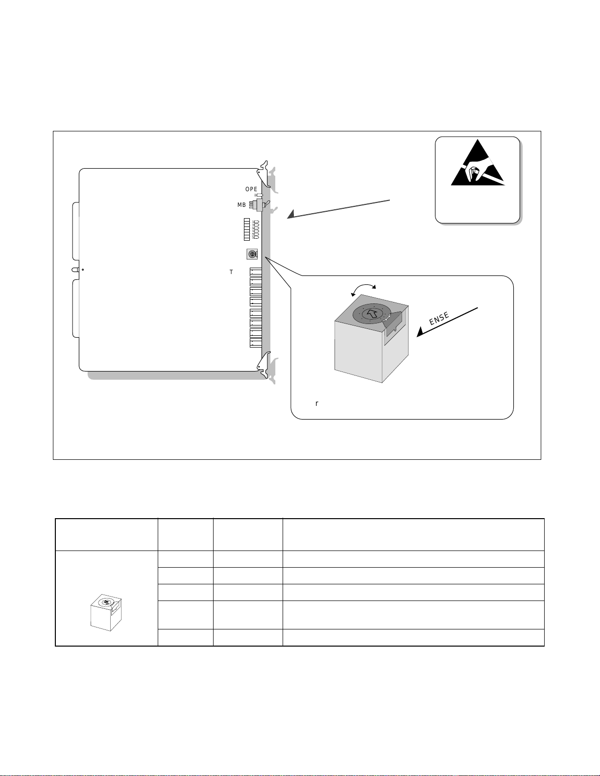
INSTALLATION
HUB (PA-M96) Card
Key Setting on Circuit Car ds
2. Key Setting on Circuit Cards
2.1 PA-M96 (HUB)
Set the SEL switch on the HUB (PA-M96) card(s), after referring to Figure 4-4 and Table 4-1.
Note:
OPE
ST7
ST0
SENSE
TP7-X
TP6-X
TP5-X
TP4-X
TP3-X
TP2-X
TP1-X
TP0-X
MB
~
CR7
CR0
4
6
2
0
A
E
C
C
E
A
0
2
6
4
HUB (PA-M96) Card
~
4
2
6
0
E
C
A
.
Set the SENSE Switch arrow to the proper direction,
referring to Table 4-1.
1 and 4 to F of the SENSE Switch are not available in this version.
Figure 4-4 Switch Setting on HUB (PA-M96) Card
ATTENTION
Contents
Static Sensitive
Handling
Precautions Required
.
SENSE Switch
Table 4-1 SENSE Switch Setting
SWITCH NAME SETTING
SENSE
0 Polarity indication on the STn lamps for TPn-Xports.
STANDARD
SETTING
1 Not used.
4
2
6
0
E
C
A
2 × TPn-X ports operate as a repeater HUB. (Standard setting)
3
Data-Packet-Collision indication on the STn lamps for TPn-X
ports.
4-F Not used.
CHAPTER 4 ND-70185 (E)
Page 32
Revision 3.0
DESCRIPTION
Page 48

INSTALLATION
FCH (PA-FCHA) Card
Key Setting on Circuit Cards
2.2 PA-FCHA (FCH)
Set the switches on the FCH (PA-FCHA) card(s) as shown below. This card has DIP switches, whose key
settings determine t he time slots of the Fusi on li nk. In Figure 4-5, CH3 is designated as the D/I channel in
an example.
D / I channel = CH3 (example)
CH:
CH:
CH:
1
OFF
16
1
OFF
8
OFF
0
2
17
2
9
2
1
1
67
4
3
8
5
SW13
19
11
4
4
3
20
5
12
5
4
22
21
67
14
13
7
6
6
5
23
8
SW12
15
8
SW11
7
18
3
10
3
2
Note: Multiple choices are
available.
ATTENTION
Contents
Static Sensitive
Handling
Precautions Required
FCH (PA-FCHA) Card
4
2
3
1
OPE
Make-busy-request
MB
EST3
OFF
OFF
Refer to Table 4-3.
SW14
LYR
LB
LOAD
MNT
10-BASE-T
4
2
3
4
2
3
1
OFF
7
8
4
2
3
6
1
5
OFF
4
2
3
7
8
5
6
1
OFF
4
67
2
3
8
1
5
OFF
1
67
4
8
3
5
2
OFF
SW14
SW13
SW12
SW11
SW10
1
MODE
OFF
7
8
4
2
3
6
1
5
OFF
2
3
1
OFF
2
3
1
OFF
1
3
2
OFF
DTI
4
7
8
5
6
4
67
8
5
FCH
67
4
8
5
EST2
EST1
EST0
PWALM
4
6
2
0
A
E
C
C
E
A
0
2
6
4
2
0
E
C
Not Used
0 1 2 3
MNT
4
6
.
A
.
MODE
ON: T203 Timer = Variable
OFF: T203 Timer = 10 secs. (Standard Setting)
7
4
2
3
1
OFF
6
5
8
SW10
Refer to Table 4-2.
Not Used
Figure 4-5 Switch Setting on FCH (PA-FCHA) Card
ND-70185 (E) CHAPTER 4
Page 33
Revision 3.0
Page 49

INSTALLATION
Key Setting on Circuit Car ds
Table 4-2 MODE Switch Setting
SWITCH NAME SETTING
STANDARD
SETTING
MODE 0-7 Not used
4
2
6
0
E
C
A
8 ×
9
A-F Not used
Table 4- 3 DIP Switch (SW14) Set tin g
SWITCH NAME
SW14
SWITCH
NUMBER
SETTING
ON × Positive logic for the D/I CONT
1
OFF Negative logic for the D/I CONT
OFF
ON ×
4
3
1
2
2
Note 1
OFF
ON ×
3
Note 1
OFF
DESCRIPTION
Standard setting
(When the DTI is connected with the card’s front cable)
Fusion link test mode
(When the DTI is connected with the card’s front cable)
STANDARD
SETTING
DESCRIPTION
The fusion data link speed inserted onto the T1
interface Note 3
SW14-2 SW14-3 SPEED (Note 2)
ON ON 64Kbps × n (1~24)
ON OFF 48Kbps × n (1~24)
OFF ON 56Kbps × n (1~24)
OFF OFF Not used
4
ON LAPD signal link performs as “network.”
OFF LAPD signal link performs as “user.”
Note 1:
64Kbps is used for T1 or E1 interface.
56Kbps is used for T1 interface with bit steali n g.
48Kbps is used for T1 interface with both bit stealing and Zero Code Suppression (o r Bit 7 Stuffing).
Note 2:
Note 3:
When n is bigger than 1, Time Slot Sequence Integrity (TSSI) must be guaranteed at the network side.
The following is an example key setting when n = 2.
SW11-1 = ON
SW11-2 = ON
ON
1
OFF
CH
021324354657687
SW11
CHAPTER 4 ND-70185 (E)
Page 34
Revision 3.0
ON
1
OFF
CH
829310411512613714815
SW12
ON
1
OFF
CH
16217318419520621722823
SW13
Page 50

INSTALLATION
Key Setting on Circuit Cards
2.3 PA-24DTR (DTI)
There are two types of the PA-24DTR (DTI) card as shown below. Refer to Figure 4-6 and Table 4-4 to set
each switch to the proper positions.
DTI (PA-24DTR) Card
Note:
Dots printed in DIP switches represe nt the standard settings.
SWITCH NAME
OPE
N-OPE
PCM
FRM
BER
RMT
AIS
SW13B
BL23
BL00
MB
CN2
SW39
12345678
OFF
SW25
1234
234
1
OFF
OFF
SW4D SW5D
12345678
12345678
OFF
OFF
12345678
OFF
SW58
12345678
2345678
1
OFF
OFF
1234
1234
OFF
OFF
12345678
234567
1
OFF
OFF
SW6C
Figure 4-6 Switch Locations on DTI (PA-24DTR) Card
Table 4-4 Switch Setting Patterns for the DTI Card
SWITCH
NUMBER
SETTING
STANDARD
SETTING
ATTENTION
Contents
Static Sensitive
Handling
Precautions Required
MEANING
MB
SW13B
1
0
UP Circuit card make busy
DOWN × Circuit card make busy cancel
0
ON Internal Loopback: Set
OFF × Internal Loopback: Cancel
1
3
2
2
ON External Loopback: Set
OFF × External Loopback: Cancel
ON Payload Loopback: Set
OFF × Payload Loopback: Cancel
3
ON All Channel Make Busy: Set Note
OFF × All Channel Make Busy: Cancel
ND-70185 (E) CHAPTER 4
Page 35
Revision 3.0
Page 51

INSTALLATION
Key Setting on Circuit Car ds
Table 4-4 Switch Setting Patterns for the DTI Card (Continued)
SWITCH NAME
SW4D
4
8
3
1
OFF
7
5
2
6
SWITCH
NUMBER
1
2
3
4
5
6
7
SETTING
STANDARD
SETTING
MEANING
ON Transmission Signal A Logic: Negative
OFF × Transmission Signal A Logic: Positive
ON Receiving Signal A Logic: Negative
OFF × Receiving Signal A Logic: Positive
ON RMT Alarm Sending: Not to be sent out
OFF × RMT Alarm Sending: To be sent out
ON ×
OFF
Simultaneous Seizure Supervision: Not to be
controlled
Simultaneous Seizure Supervisi on: To be controlled
ON Data Link Control: MOS
OFF × Data Link Control: BOS
ON Multiframe Selection: 12-Multiframe
OFF Multiframe Selection: 24-Multiframe
ON
OFF
Signal Selection: AMI (Alternate Mark Inversion)
Signal Selection: B8ZS (Bipolar with 8 Zeros
Substitution)
OFF
SW25
1
2
8ON × Fixed
ON × Impedance setting: 100 Ω
1
OFF Impedance setting: 110 Ω
4
3
ON
Transformer at Middle Point – Transmission:
Ground
2
OFF ×
Transformer at Middle Point – Transmission:
Open
ON Transformer at Middle Point Receive: Ground
3
OFF × Transformer at Middle Point Receive: Open
ON Idle Code: To be sent out
4
OFF × Idle Code: Not to be sent out
CHAPTER 4 ND-70185 (E)
Page 36
Revision 3.0
Page 52

Key Setting on Circuit Cards
Table 4-4 Switch Setting Patterns for the DTI Card (Continued)
INSTALLATION
SWITCH NAME
SW39
4
8
3
1
OFF
7
5
2
6
SWITCH
NUMBER
1
2
3
4
5
SETTING
ON
OFF ×
ON ×
OFF
ON ×
OFF
ON ×
OFF
ON ×
OFF
STANDARD
SETTING
MEANING
SW39-1 SW39-2 PAD CONTROL
ON ON Both directions
OFF ON Receiving only
ON OFF Sending on ly
OFF OFF ARTD is fixed
SW39-3 SW39-4 DATA PAD
ON ON 64K
OFF ON 56K
ON OFF 48K
OFF OFF 64K INV.
ON
SW39-5 SW39-6 T SIG CONTROL
ON ON ABCD
OFF ON ABAB
6
OFF ×
ON OFF
Bit steal is in-
hibited
OFF OFF AAAA
ON ×
7
OFF
ON
8
OFF ×
SW39-7 SW39-8 R SIG CONTROL
ON ON ABCD
OFF ON ABAB
ON OFF
Bit steal is in-
hibited
OFF OFF AAAA
ND-70185 (E) CHAPTER 4
Page 37
Revision 3.0
Page 53

INSTALLATION
Key Setting on Circuit Car ds
Table 4-4 Switch Setting Patterns for the DTI Card (Continued)
SWITCH NAME
SW6C
4
8
3
1
OFF
7
5
2
6
SW58
4
8
3
1
OFF
7
5
2
6
SWITCH
NUMBER
SETTING
STANDARD
SETTING
1ON × Fixed
2ON × Fixed
3ON × Fixed
4ON × Fixed
5ON × Fixed
6ON × Fixed
7ON × Fixed
8ON × Fixed
ON Equalizer Setting
1
OFF
ON
2
OFF
ON
3
OFF
MEANING
SW
58-1
ON ON ON
ON ON OFF
ON OFF ON
ON OFF OFF
OFF ON ON
SW
58-2
Other Combinations Not Allowed
SW
58-3
DISTANCE
0 - 131 ft
(0 - 040 m)
131 - 262 ft
(40 - 080 m)
262 - 393 ft
(80 - 120 m)
393 - 524 ft
(120 - 160 m)
524 - 656 ft
(160 - 200 m)
ON
4
OFF ×
ON ×
5
OFF
ON ×
6
OFF
ON
7
OFF ×
ON ×
8
OFF
CHAPTER 4 ND-70185 (E)
Page 38
Revision 3.0
PAD Pattern Selection
SW
58-4
OFF ON ON PAD Pattern 1
OFF ON OFF PAD Pattern 2
ON OFF ON
ON OFF OFF A→ µ Loss (Receive)
OFF OFF ON
OFF OFF OFF µ→A Loss (Receive)
SW
58-5
SW
58-6
PAD PATTERN
A→ µ Loss
(Bothway)
µ→A Loss
(Bothway)
Other Combinations Not Allowed
Note: When setting this key, refer to Digital
PAD Setting Table (Table 4-5).
Alarm Sending when this circuit card is in NOPE state.
Page 54

Key Setting on Circuit Cards
Table 4-4 Switch Setting Patterns for the DTI Card (Continued)
INSTALLATION
SWITCH NAME
SW5D
4
3
1
2
OFF
Note:
This switch setting is applicable for a system which adopts Associated Channel Interoffice Signalling
(ACIS).
2.4 Digital PAD Setting
The PA-24DTR card is equipped with a mask R OM in which th e follo wing t ypical PAD patterns hav e been
already written. PAD value is determined by selecting a desired PAD pattern, which can be done by key
setting of the SW 58 (elements 4, 5, 6) on the card, and programming of the PAD data by the ARTD command - CDN = 30 (PAD). The PAD patterns and ARTD data correspond as follows.
SWITCH
NUMBER
SETTING
ON
STANDARD
SETTING
MEANING
Digital PAD ROM selection: Special specification
1
OFF ×
Digital PAD ROM selection: Standard specification
ON × LAYER2 signal logic: Posi tive
2
OFF LAYER2 si gnal logic: Negative
ON Line fault is not notified to the upper CPU
3
OFF × Line fault is notified to the upper CPU
4 ON Zero Code Suppression is not provided
PAD
DAT A
ARTD
CDN=
30
1
2
3
4
5
7
Note:
Table 4-5 Digital Pad Setting
PAD Pattern [dB] (Selected by key setting)
PAD Pattern 1 PAD Pattern 2
SEND RECEIVE SEND RECEIVE SEND RECEIVE SEND RECEIVE SEND RECEIVE SE ND RECEIVE
22
-3
Note
300000000
A→µ Loss
(Bothway)
A→µ Loss
(Receive)
A Loss
µ→
(Bothway)
A Loss
µ→
(Receive)
44334 4 044404
6606 6 6 0 12 6 6 0 12
88398 8 088808
Key setting of SW 39-3,4 correspond to PAD values. (Regardless of PAD patterns)
0 0 0 0 Through Through Through Through Through Through Through Through
Stands for 3[dB] GAIN.
ND-70185 (E) CHAPTER 4
Page 39
Revision 3.0
Page 55

INSTALLATION
Mounting Circuit Cards in PIM
3. Mounting Circuit Cards in PIM
3.1 Mounting HUB (PA-M96) in a PIM
Mount the HUB (PA-M96) card in an appropriate slot of a PIM as shown below. When the MAT is connected via a HUB card, be sure to use a dedicat ed HUB for the Fusion link.
Note:
HUB (PA-M96) can be mounted wherever in a PIM of any IMG stack. However, if your system is 1-IMG
type, mount the HUB in PIM0.
Mount a HUB card in an appropriate slot providing the anti-static kit.
PIM 1
PIM 0
HUB
HUB
PA-M96
ATTENTION
Contents
Static Sensitive
Handling
Precautions Required
Anti-static Kit
Figure 4-7 Mounting HUB Card in PIM 0
CHAPTER 4 ND-70185 (E)
Page 40
Revision 3.0
Page 56

INSTALLATION
Mounting Circuit Cards in PIM
3.2 Mounting FCH (PA-FCHA) and DTI (PA-24DTR) Cards
Mount the FCH (PA-FCHA) and the DTI (PA-24DTR) card in appropriate slots in a PIM. Mount the two
cards in adjacent slots since these cards must be connected on the front connectors. Figure 4-8 shows an
example with the FCH and DTI cards mounted in PIM 1.
This figure shows an example where FCH and DTI cards are mounted in PIM 1.
PIM 1
PIM 0
FCH (PA-FCHA)
DTI (PA-24DTR)
FCCH(PA-FCCHA)
DTI (PA-24DTR)
HUB
HUB
HUB
HUB
ATTENTION
Contents
Static Sensitive
Handling
Precautions Required
Anti-static Kit
Figure 4-8 Mounting FCH and DTI Cards
ND-70185 (E) CHAPTER 4
Page 41
Revision 3.0
Page 57

INSTALLATION
Connecting Cables
4. Connecting Cables
4.1 Connecting DTI-FCH Front Cables
Connect the furnished fro nt cable to the conn ector s on the DTI and FCH car ds . Use DTI and CN2 connectors on the FCH and DTI cards respectively. Since an FCH card is equipped with one Handler circuit, a
maximum of five FCH cards can be connected to a DTI card. (See Figure 4-10.) However, if a DCH card
is also cascaded, a maxi mum of three FCH cards can be added to the DTI car d. (DCH is equi pped with t wo
Handler circuits per card.)
Connect "10AL(10)FLT CA" to the connectors.
FCH (PA-FCHA)
OPE
MB
10AL(10)FLT CA
2
10AL(10)FLT CA
DTI (PA-24DTR)
OPE
MB
ATTENTION
Contents
Static Sensitive
Handling
Precautions Required
2
DTI
FCH
FRONT VIEW
CN2
10AL(10)FLT CA
Figure 4-9 Connecting Front Cables
Anti-static Kit
FRONT VIEW
CHAPTER 4 ND-70185 (E)
Page 42
Revision 3.0
Page 58

INSTALLATION
Connecting Cables
Since a maximum of five Handler circuits can be used, five FCH cards can be cascaded. Figure 4-10 shows an
example where three FCH cards are cascaded.
Since a maximum of five " Handler" circuits can be used, five FCH cards can be cascaded. This figure shows an example where three
FCH cards are cascaded.
FCH x 3
DTI
FCH(PA-FCHA)
DTI
ATTENTION
Contents
Static Sensitive
Handling
Precautions Required
(PA-24DTR)
2
2
2
DTI
10AL(10)FLT CA
10AL(10)FLT CA
OVERVIEW
CN2
FCH
FRONT VIEW
Figure 4-10 FCH Cascade Connections
ND-70185 (E) CHAPTER 4
Page 43
Revision 3.0
Page 59

INSTALLATION
Connecting Cables
4.2 Connecting 10 BASE-T Cables
Figure 4-11 shows sample cable connections, where HUB (PA-M96) cards are provided in a dual configu-
ration and the FCH (PA-FCHA) card is located in PIM 1 (1-I MG system/IMG0). When HUB cards are provided in a dual confi guration, the two HUB cards must be connected on each front ed ge connector using a
10 BASE-T cross cable. However, when dual LANIs (LANI-A and LANI-B) are used for each CPU, the
cross cable connection between HUBs for FCH#0 and #1 is not necessary.
Note:
The Ethernet cables s hown in the e xample s in this sect ion are NOT available from NEC. These cables must
be pro vided by the cus tomer, depending on the syste m configur ation. See “Cha pter 6 Connecting 10 B ASE-
T Cables.”
DTI (PA-24DTR)
ATTENTION
Contents
Static Sensitive
Handling
Precautions Required
10 BASE T cable
(straight)
PIM 1
PIM 0
FCH (PA-FCHA)
HUB
(PA-M96)
DTI
10 BASE T cable
(cross)
HUB
(PA-M96)
HUB
(PA-M96)
LANI (PZ-PC19)
GT
MAT
REAR VIEW
to MAT
Note
: 10 BASE-T cable (for Fusion Link)
Note:
When connecting the MAT using a HUB card, be sure to use a dedicated HUB for the MAT.
Figure 4-11 Overall 10 BASE-T Connections
CHAPTER 4 ND-70185 (E)
Page 44
Revision 3.0
GT
LANI (PZ-PC19)
10 BASE T cable
(straight)
: 10 BASE-T cable (for MAT)
Page 60

INSTALLATION
Connecting Cables
4.3 10 BASE-T Connection Procedure
The pattern for 10 BASE-T cable connections may vary, depending on the system configuration (such as
number of IMG stacks or the mounting location/number of the FCH/HUB cards, etc.). According to your
system configuration, connect necessary Ethernet cables:
4.3.1 Procedure for 1-IMG System
If your system is 1-IMG type, the 10 BASE-T connection should use either of the following cables:
1. Cable unit specified as SR1201 ETIF CAU-n
2. Cables, other than those of SR1201 ETIF CAU-n, that are provided by the user
Based on the cable type, perform the following:
4.3.2 When using cable uni t S R1201 ETIF CAU-n
1. Referring to any of Figure 4-13 through Figure 4-15, connect the 10 BASE-T straight cables, be-
tween the LANI (PZ-PC19) and HUB (PA-M96) cards, and between the HUB and FCH (PAFCHA) cards. If the HUB is in a dual configuration, also connect the 10 BASE-T cross cable between HUB#0 and HUB#1.
Note:
When dual LANIs are used in both Slot 00 and 03 of CPR#0/CPR#1, be sure to use at least two
HUB cards. Use one HUB for the internal LANI (in Slot 00) and use the other HUB for external
LANI (in Slot 03, available for Series 7300 Release 3 software or later). If FCH is also in a dual
configuration, the 10 BASE-T cross connec ti on between the two HUBs is not required.
2. If your system needs more FCH (PA-FCHA) and/or HUB (PA-M96) cards, provide the required
Ethernet connection(s) for the added card(s) using the following cables:
• When adding FCH card in PIM0: UTP CTG5 ST CA-D
• When adding HUB card in PIM0: UTP CTG5 CRS CA-D
• When adding FCH card in PIM1: UTP CTG5 ST CA-K
• When adding HUB card in PIM1: UTP CTG5 CRS CA-K
• When adding FCH card in PIM2: UTP CTG5 ST CA-M
• When adding HUB card in PIM2: UTP CTG5 CRS CA-M
• When adding FCH card in PIM3: UTP CTG5 ST CA-N
• When adding HUB card in PIM3: UTP CTG5 CRS CA-N
The cables, cited above and used in Figure 4-13 through Figure 4-15, are for the 1-IMG system on ly (not
available in the 4-IMG/IMX- U syst em).
ND-70185 (E) CHAPTER 4
Page 45
Revision 3.0
Page 61

INSTALLATION
Connecting Cables
4.3.3 When not using the cable unit SR1201 ETIF CAU-n
When your system doesn’ t use t he cable unit cla ssif ied as SR1201 ETIF CAU-n, perform the 10 B ASET connections as instructed below:
1. Depending on your system configuration, connect the 10 BASE-T straight cable(s) between the
HUB (PA-M96) and LANI (PZ-PC19) cards. Use the cable UTP CTG5 ST CA-O, which must be
provided by the user.
When a single LANI is used for each CPR (Slot 00 only) and the HUB is in a dual configuration,
connect HUB#0 to LANI#0 and HUB#1 to LANI#1, using two 10 BASE-T cables.
When dual LANIs are used in both Slot 00 and 03 of CPR#0/CPR#1, use at least two HUB cards
as separate 10 BASE-T connection terminals: One HUB for the internal LANI (LANI-A in Slot 00
0f each CPR) and the other for the external LANI (LANI-B: in Slot 03 of each CPR) The external
LANI is available for Series 7300 Release 3 software or later.
2. When HUB is in a dual conf i gurati on, con nect t he 10 BASE-T cross cable between the HUB cards.
Use the cable UTP CTG5 CRS CA-F, which must be provided by the user.
When using more than two HUB cards, connect the cross cable(s) for the remaining HUB cards,
except the HUB card used for the MAT connection.
3. Connect the 10 BASE-T straight cable(s) between the HUB and FCH (PA-FCHA) cards. Use the
following cables, which must be provided by the user.
UTP CTG5 ST CA-F: When the HUB and FCH are in the same PIM (PIM0)
UTP CTG5 ST CA-O: When the HUB and FCH are in different PIMs
When FCH is in a dual configura tion, connect FCH#0 to the HUB#0 side, and FCH#1 to the HUB#1
side.
4.3.4 Procedure for 4-IMG System
When your system is 4-IMG type, the procedure for 10 BASE-T connection is as follows. Because the
HUB (PA-M96) can be mounted anywhere i n a PIM of any IMG, the Ethernet cables must be arranged
by the user, depending on the system configuration.
1. Depending on your system configuration, connect the 10 BASE-T straight cable(s) between the
HUB (PA-M96) and LANI (PZ-PC19) cards. Use the following cable, prepared by the user.
UTP CTG5 ST CA-O: When the HUB and LANI are in the same IMG (IMG0)
UTP CTG5 ST CA-X: When the HUB and LANI are in different IMGs
When a single LANI is used for each CPR (Slot 00 only) and the HUB is in a dual configuration,
connect HUB#0 and HUB#1 to LANI#1 using two 10 BASE-T cables.
CHAPTER 4 ND-70185 (E)
Page 46
Revision 3.0
Page 62

INSTALLATION
Connecting Cables
When dual LANIs are used in both Slot 00 and 03 of CPR#0/CPR#1, be sure to use at least two
HUB cards as separate 10 BASE-T connection terminals. Use one HUB for the internal LANI
(LANI-A: in Slot 00 of each CPR) and use the other for the external LANI (LANI-B in Slot 03 of
each CPR).
2. When the HUB is in a dual configuration, connect the 10 BASE-T cross cable between the HUB
cards. Use the following cables, which are provided by the user.
UTP CTG5 CRS CA-F:When the HUB and HUB are in the same PIM
UTP CTG5 CRS CA-O:When the HUB and HUB are in different PIMs but in the same IMG
UTP CTG5 CRS CA-X:When the HUB and HUB are in different IMG stacks
When using more than two HUB cards, also connect the cross cable(s) for the remaining HUB
card(s), except the HUB for the MAT connection.
This step is not necessary when your system uses dual LANIs for CPU#0/CPU#1 and FCH is also
in a dual configuration.
3. Connect the 10 BASE-T straight cable(s) between the HUB and FCH (PA-FCHA) cards. Use the
following cable, which must be provided by the user.
UTP CTG5 ST CA-F: When the HUB and FCH are in the same PIM
UTP CTG5 ST CA-O: When the HUB and FCH are in different PIMs but in the same IMG
UTP CTG5 ST CA-X: When the HUB and FCH are in different IMG stacks
When FCH is in a dual configura tion, connect FCH#0 to the HUB#0 side, and FCH#1 to the HUB#1
side.
4.3.5 Procedure for IMX-U System
When your system is the IMX-U type (configured to a maximum of 4 Local Nodes + 1ISW), the procedure for the 10 BASE-T connection is as follows. Because this system already has a Fusion Link via
the HUB (P A-M96) cards, this section gi ves detai ls related only to the connect ion between the HUB and
FCH (PA-FCHA) cards.
1. Refer to the NEAX2400 IMX Installation Manual (IMX-U Type) to make sure that the necessary
10 BASE-T (both straight and cross) connections between the ISW and each LN (Local Node) are
all securely provided.
2. Connect the 10 B ASE-T s traight cable(s) be tween the HUB ( PA-M96) and FCH (PA-FCHA) cards.
Use the following cable, which must be provided by the user.
UTP CTG5 ST CA-F: When the HUB and FCH are in the same PIM
UTP CTG5 ST CA-O:When the HUB and FCH are in different PI Ms but in the same IMG
UTP CTG5 ST CA-X:When the HUB and FCH are in different IMG stacks but in the same LN
UTP CTG5 ST CA-A0:When the HUB and FCH are in different LNs
ND-70185 (E) CHAPTER 4
Page 47
Revision 3.0
Page 63

INSTALLATION
Connecting Cables
When dual FCH is provided for the HUB dedicated to each internal LANI card (LANI-A: in Slot
00 of each CPR), connect FCH#0 to HUB#0 and FCH#1 to HUB#1.
When your system also uses the external LANI cards (LANI-B in Slot 03 of each CPR), prepare
another set of FCH cards for the HUB dedicated to the external LANI cards. Then, if the FCH is in
dual configuration, connect one FCH to the HUB for No. 0 system of the external LANI, and the
other to the HUB for the No. 1 system of the external LANI.
Figure 4-12 sho ws an e xa mple of a HUB in a du al co nf igur atio n a nd th e FCH c ard moun ted i n PIM
1 of the 1 IMG system.
This figure shows an example where HUB is provided in a dual configuration and FCH card is mounted in PIM1 of 1-IMG system.
PIM 1
3
Connect HUB and FCH using a
10 BASE-T straight cable.
Refer to figures listed on the
following pages.
2
Connect two HUB cards using
a 10 BASE-T cross cable.
(When HUB is in dual
configuration.) Note
PIM 0
1
Connect the LANI and the
HUB card using a 10 BASE-T
straight cable. Eight
10 BASE-T connectors
(TP0-X - TP7-X) are
-
furnished on the front edge
of the HUB card. Use one of
the connectors.
(PA-M96)
HUB
FCH
LANI
LANI
Note
Note
(PA-M96
HUB
2
)
DTI
DTI
ATTENTION
Contents
Static Sensitive
Handling
Precautions Required
3
1
GT
GT
1
Note:
This step can be skipped when dual LANIs (LANI-A and LANI-B) are used for each CPU and FCH is
provided in a dual configuration.
Figure 4-12 Connecting 10 BASE-T Cables (example)
CHAPTER 4 ND-70185 (E)
Page 48
Revision 3.0
Page 64

INSTALLATION
Connecting Cables
Figure 4-13 shows some typi cal example s, where 10 BASE-T cab les are co nnected to the FCH card( s) mounted
in PIM0 of 1-IMG system, under the following conditions:
Configuration
of CPU
Configuration
of LAN
Used Cable Unit
(Note 1, Note 2)
Number of HUB/
Pattern 1 Single Single SR1201 ETIF CAU-A × 1 HUB× 1, FCH× 1
Pattern 2 Dual Single
SR1201 ETIF CAU-A × 1
SR1201 ETIF CAU-DA × 1
HUB× 2, FCH× 2
Pattern 3 Single Dual SR1201 ETIF CAU-A × 2 HUB× 2, FCH× 2
Pattern 4 Dual Dual
Note 1:
Cables Contained in each cable unit are as follows.
SR1201 ETIF CAU-A × 2
SR1201 ETIF CAU-DA × 2
HUB× 2, FCH× 2
SR1201 ETIF CAU-A: UTP CTG5 ST CA-D, UTP CTG5 ST CA-J
SR1201 ETIF CAU-DA: UTP CTG5 ST CA-D, UTP CTG5 ST CA-J, UTP CTG5 CRS CA-F
Note 2:
The cables cited in Figure 4-13 can be used in the 1-IMG system only. Refer to Page 45 through Page 4 8
for more details.
FCH
HUB
(PA-M96)
CN
Use 10 BASE-T connectors.
Connectors for 10 BASE-T
(PA-FCHA)
= 10 BASE-T Connector
TP7-X
TP6-X
TP5-X
TP4-X
TP3-X
TP2-X
TP1-X
TP0-X
10 BASE-T
<FCH in PIM0 (Pattern 1)> <FCH in PIM0 (Pattern 2)>
TOPU
PIM 3
Contents
Static Sensitive
Handling
Precautions Required
TOPU
PIM 3
FCH
ATTENTION
FRONT VIEW
FRONT VIEW
FANU
CN
CN
CN
UTP CTG5 ST CA-D
HUB
FCH
UTP CTG5 ST CA-J
BASEU
PIM 2
FANU
PIM 1
UTP CTG5 CRS CA-F
CN
CN
PIM 0
06040503020100
BSCM
LPM
06040503020100
CN
CN
CN
UTP CTG5 ST CA-D
FCH
HUB
UTP CTG5 ST CA-J
BASEU
CNCN
PIM 2
PIM 1
CN
CN
CN
PIM 0
CN
FCH
HUB
06040503020100
BSCM
06040503020100
LPM
Figure 4-13 Examples of Ethernet Cable Connection-FCH in PIM0 (1-IMG System) (1/2)
ND-70185 (E) CHAPTER 4
Revision 3.0
Page 49
Page 65

INSTALLATION
Connecting Cables
<FCH in PIM0 (Pattern 3)> <FCH in PIM0 (Pattern 4)>
ATTENTION
Contents
Static Sensitive
Handling
Precautions Required
PIM 3
PIM 2
PIM 1
PIM 0
UTP CTG5 ST CA-J
LPM
CN
CN
CN
CN
UTP CTG5 ST CA-D
HUB
FCH
TOPU
FANU
UTP CTG5 ST CA-J
CN
CN
CN
CN
HUB
FCH
06040503020100
06040503020100
CN
CN
BSCM
BSCM
TOPU
FANU
UTP CTG5 ST CA-D
CN
CN
CN
CN
CN
FCH
HUB
UTP CTG5 ST CA-J
CN
FCH
CN CN
CN
CN
PIM 3
PIM 2
PIM 1
CN CN
CN CN
PIM 0
HUB
06040503020100
UTP CTG5 ST CA-J
06040503020100
LPM
BASEU
BASEU
Note: When dual LANIs are used in both slot 00 and 03 of CPR (Pattern 3 or 4), be sure to use at least two HUB cards:
One HUB for internal LANI (in slot 00) and the other for external LANI (in slot 03: available for Release 3 or
later software). However, if this is the case and FCH is also in a dual configuration, the 10 BASE-T “cross”
connection between the HUBs is not required.
Figure 4-13 Examples of Ethernet Cable Connection-FCH in PIM0 (1-IMG System) (2/2)
CHAPTER 4 ND-70185 (E)
Page 50
Revision 3.0
Page 66

INSTALLATION
Connecting Cables
Figure 4-14 shows some typi cal example s, where 10 BASE-T cab les are co nnected to the FCH card( s) mounted
in PIM1 of 1-IMG system, under the following conditions:
Configuration
of CPU
Configuration
of LAN
Used Cable Unit
(Note 1, Note 2)
Number of HUB/
Pattern 1 Single Single SR1201 ETIF CAU-B × 1 HUB× 1, FCH× 1
Pattern 2 Dual Single
SR1201 ETIF CAU-B × 1
SR1201 ETIF CAU-DB × 1
HUB× 2, FCH× 2
Pattern 3 Single Dual SR1201 ETIF CAU-B × 2 HUB× 2, FCH× 2
Pattern 4 Dual Dual
Note 1:
Cables contained in eac h cable unit are as follows.
SR1201 ETIF CAU-B × 2
SR1201 ETIF CAU-DB × 2
HUB× 2, FCH× 2
SR1201 ETIF CAU-B: UTP CTG5 ST CA-K, UTP CTG5 ST CA-J
SR1201 ETIF CAU-DB: UTP CTG5 ST CA-I, UTP CTG5 ST CA-J, UTP CTG5 CRS CA-F
Note 2:
The cables cited in Figure 4-14 can be used in the 1-IMG system only. Refer to Page 45 through Page 4 8
for more details.
FCH
HUB
CN
Use 10 BASE-T connectors.
Connectors for 10 BASE-T
(PA-FCHA)
(PA-M96)
= 10 BASE-T Connector
TP7-X
TP6-X
TP5-X
TP4-X
TP3-X
TP2-X
TP1-X
TP0-X
10 BASE-T
<FCH in PIM1 (Pattern 1)> <FCH in PIM1 (Pattern 2)>
TOPU
PIM 3
TOPU
ATTENTION
Contents
Static Sensitive
Handling
Precautions Required
PIM 3
FCH
FRONT VIEW
FRONT VIEW
FANU
CN
FCH
CN
UTP CTG5 ST CA-K
CN
HUB
UTP CTG5 ST CA-J
BASEU
PIM 2
FANU
PIM 1
PIM 0
06040503020100
BSCM
LPM
06040503020100
CN
CN
FCH
CN CN
UTP CTG5 ST CA-K
CN
HUB
UTP CTG5 CRS CA-F
UTP CTG5 ST CA-J
BASEU
CN
CN
UTP CTG5 ST CA-I
CN
FCH
CN CN
CN
HUB
PIM 2
PIM 1
PIM 0
06040503020100
06040503020100
BSCM
LPM
Figure 4-14 Examples of Ethernet Cable Connection-FCH in PIM1 (1-IMG System)
ND-70185 (E) CHAPTER 4
Page 51
Revision 3.0
Page 67

INSTALLATION
Connecting Cables
Figure 4-15 shows some typi cal example s, where 10 BASE-T cab les are co nnected to the FCH card( s) mounted
in PIM2 of 1-IMG system, under the following conditions:
Configuration
of CPU
Configuration
of LAN
Used Cable Unit
(Note 1, Note 2)
Number of HUB/
Pattern 1 Single Single SR1201 ETIF CAU-C × 1 HUB× 1, FCH× 1
Pattern 2 Dual Single
SR1201 ETIF CAU-C × 1
SR1201 ETIF CAU-DC × 1
HUB× 2, FCH× 2
Pattern 3 Single Dual SR1201 ETIF CAU-C × 2 HUB× 2, FCH× 2
Pattern 4 Dual Dual
Note 1:
Cables contained in eac h cable unit are as follows.
SR1201 ETIF CAU-C × 2
SR1201 ETIF CAU-DC × 2
HUB× 2, FCH× 2
SR1201 ETIF CAU-C: UTP CTG5 ST CA-M, UTP CTG5 ST CA-J
SR1201 ETIF CAU-DC: UTP CTG5 ST CA-K, UTP CTG5 ST CA-J, UTP CTG5 CRS CA-F
Note 2:
The cables cited in Figure 4-15 can be used in the 1-IMG system only. Refer to Page 45 through Page 4 8
for more details.
FCH
HUB
CN
Use 10 BASE-T connectors.
Connectors for 10 BASE-T
(PA-FCHA)
(PA-M96)
= 10 BASE-T Connector
TP7-X
TP6-X
TP5-X
TP4-X
TP3-X
TP2-X
TP1-X
TP0-X
FRONT VIEW
FRONT VIEW
10 BASE-T
<FCH in PIM2 (Pattern 1)> <FCH in PIM2 (Pattern 2)>
TOPU
PIM 3
CN
FCH
PIM 2
CN
FCH
CN
FCH
ATTENTION
Contents
Static Sensitive
Handling
Precautions Required
TOPU
PIM 3
UTP CTG5 ST CA-K
PIM 2
FCH
FANU
PIM 1
CN
UTP CTG5 ST CA-M
CN
HUB
UTP CTG5 ST CA-J
CN
BASEU
PIM 0
06040503020100
LPM
06040503020100
BSCM
Figure 4-15 Examples of Ethernet Cable Connection-FCH in PIM2 (1-IMG System) (1/2)
CHAPTER 4 ND-70185 (E)
Page 52
Revision 3.0
FANU
UTP CTG5 ST CA-M
CN
CN
CN
UTP CTG5 CRS CA-F
HUB
UTP CTG5 ST CA-J
BASEU
PIM 1
CN CN
CN
PIM 0
HUB
06040503020100
CN
CN
BSCM
LPM
06040503020100
Page 68

<F C H in P IM2 (P a tte rn 3 )> <FC H in P IM2 (P a tte rn 4 )>
INSTALLATION
Connecting Cables
ATTENTION
Contents
Static Sensitive
Handling
Precautions Required
TOPU
PIM 3
PIM 2
PIM 1
PIM 0
LPM
CN
FCH
UTP CTG5 ST CA-M
CN
CN
CN
HUB
UTP CTG5 ST CA-J
FANU
CN
FCH
UTP CTG5 ST CA-J
CN CN
CN
HUB
CN
CN
0604 0503020100
BSCM BSCM
0604 0503020100
CN
FCH
FANU
UTP CTG5 ST CA-M
CN
CN
CN
HUB
UTP CTG5 ST CA-J
CN
FCH
CN CN
CN
CN
TOPU
PIM 3
UTP CTG5 ST CA-K
PIM 2
PIM 1
CN
PIM 0
CN
CN
HUB
0604 0503020100
UTP CTG5 ST CA-J
0604 0503020100
LPM
BASEU
Note:
BASEU
When dual LANIs are used in both Slot 00 and 03 of CPR (Pattern 3 or 4), be sure to use at least
two HUB cards : One HUB for internal LANI (in Sl ot 0 0) and the other for external LANI (in Slot
03). However, if this is the case and FCH is also in a dual configuration, the 10 BASE-T “cross”
connection between the HUBs is not required.
Figure 4-15 Examples of Ethernet Cable Connection-FCH in PIM2 (1-IMG System) (2/2)
ND-70185 (E) CHAPTER 4
Page 53
Revision 3.0
Page 69

INSTALLATION
Connecting Cables
Figure 4-16 shows some typi cal example s, where 10 BASE-T cab les are co nnected to the FCH card( s) mounted
in PIM3 of 1-IMG system, under the following conditions:
Configuration
of CPU
Configuration
of LAN
Used Cable Unit
(Note 1, Note 2)
Number of HUB/
Pattern 1 Single Single SR1201 ETIF CAU-D × 1 HUB× 1, FCH× 1
Pattern 2 Dual Single
SR1201 ETIF CAU-D × 1
SR1201 ETIF CAU-DD × 1
HUB× 2, FCH× 2
Pattern 3 Single Dual SR1201 ETIF CAU-D × 2 HUB× 2, FCH× 2
Pattern 4 Dual Dual
Note 1:
Cables contained in eac h cable unit are as follows.
SR1201 ETIF CAU-D × 2
SR1201 ETIF CAU-DD × 2
HUB× 2, FCH× 2
SR1201 ETIF CAU-D: UTP CTG5 ST CA-N, UTP CTG5 ST CA-J
SR1201 ETIF CAU-DD: UTP CTG5 ST CA-L, UTP CTG5 ST CA-J, UTP CTG5 CRS CA-F
Note 2:
The cables cited in Figure 4-16 can be used in the 1-IMG system only. Refer to Page 45 through Page 4 8
for more details.
FCH
HUB
CN
Use 10 BASE-T connectors.
Connectors for 10 BASE-T
(PA-FCHA)
(PA-M96)
= 10 BASE-T Connector
TP7-X
TP6-X
TP5-X
TP4-X
TP3-X
TP2-X
TP1-X
TP0-X
10 BASE-T
<FCH in PIM3 (Pattern 1)> <FCH in PIM3 (Pattern 2)>
TOPU
CN
PIM 3
FCH
TOPU
CN
FCH
CN
FCH
ATTENTION
Contents
Static Sensitive
Handling
Precautions Required
UTP CTG5 ST CA-L
PIM 3
FCH
FRONT VIEW
FRONT VIEW
FANU
CN
CN
UTP CTG5 ST CA-N
HUB
UTP CTG5 ST CA-J
BASEU
PIM 2
PIM 1
PIM 0
06040503020100
BSCM
LPM
06040503020100
CN
Figure 4-16 Examples of Ethernet Cable Connection-FCH in PIM3 (1-IMG System) (1/2)
CHAPTER 4 ND-70185 (E)
Page 54
Revision 3.0
UTP CTG5 ST CA-N
CN CN
CN
UTP CTG5 CRS CA-F
HUB
UTP CTG5 ST CA-J
FANU
BASEU
PIM 2
PIM 1
CN
CN
PIM 0
CN
HUB
06040503020100
CN
CN
BSCM
06040503020100
LPM
Page 70

<FCH in PIM3 (P a ttern 3 )> <F C H in P IM3 (P a ttern 4)>
INSTALLATION
Connecting Cables
ATTENTION
Contents
Static Sensitive
Handling
Precautions Required
TOPU
PIM 3
PIM 2
PIM 1
PIM 0
LPM
CN
FCH
FANU
UTP CTG5 ST CA-N
CN
CNCN
HUB
UTP CTG5 ST CA-J
CN
FCH
UTP CTG5 ST CA-J
CN
CN
CN
HUB
CN
CN
06040503020100
BSCM BSCM
06040503020100
CN
FCH
FANU
UTP CTG5 ST CA-N
CN
CN
CN
HUB
UTP CTG5 ST CA-J
CN
FCH
CN CN
CN
CN
TOPU
PIM 3
PIM 2
UTP CTG5 ST CA-L
PIM 1
CN CN
PIM 0
CN
HUB
06040503020100
UTP CTG5 ST CA-J
06040503020100
LPM
Note:
BASEU
BASEU
When dual LANIs are used in both Slot 00 and 03 of CPR (Pattern 3 or 4), be sure to use at least two
HUB cards: One HUB for internal LANI (in Slot 00) and the other for external LANI (in Slot 03).
However, if this is the case and FCH is also in a dual configuration, the 10 BASE-T ”cross”
connection between the HUBs is not required.
Figure 4-16 Examples of Ethernet Cable Connection-FCH in PIM3 (1-IMG System) (2/2)
ND-70185 (E) CHAPTER 4
Page 55
Revision 3.0
Page 71

This page is for your notes.
CHAPTER 4 ND-70185 (E)
Page 56
Revision 3.0
Page 72

CHAPTER 5 DATA PROGRAMMING
This chapt er explains h ow to set Fusion Network data, using t he following data categories:
• System Data
• Numbering Plan Data
• Station D ata
• Fusion Link Data
Figure 5-1 shows the overall data programming proced ure:
System Data
Numbering Plan Data
Station Number Data
ASYDN
NCN:
LN:
ASYDL
ANPD ANPDL
ASPA ASPAL
STN
SSC
SSCA
OGC
OGCA
LCR
LCRS
UNIF
:
:
:
------
Physical Number
ASDT
AFMU
ALRTN
------
SSC
------
OGC
OGCA
LCR
LCRS
:
:
:
TELN Note
Telephone Number
ALGNL
ALGSL
Note: Telephone Number is
available only in self
node.
ANPDN
----SSC
SSCA
OGC
OGCA
LCR
LCRS
:
:
:
:
TELN
Telephone Number
ALGNN
ALGSN
ASPAN
Fusion Link Data
with FCH
w/o FCH
ACRD
ACRD
AFRT
ACTK
MBCT
AFCH
AFPC
Figure 5-1 Data Programming Flow Chart
ND-70185 (E) CHAPTER 5
AFPC
ACAN
: Available command at NCN.
Page 57
Revision 3.0
Page 73

DATA PROGRAMMING
Network Data Programming Summary
1. Network Data Programming Summary
This sectio n explains a summary of th e data programming of Fusio n system s .
1.1 Brand-new Fusion Network
T o i nstall the Fusion n etwork as a brand-ne w syst em, the o verall data progr amming procedur e is as f ollo ws.
1.1.1 System Data
• Decide an NCN, and LN on the network.
• Assign System Data for each node. Use the ASYDN command for the NCN and the ASYDL command for all nodes. The system data inc ludes the size of LDM, NDM, Fusion Point Cod e (FPC), etc.
Note:
The data becomes effective by executing “Non-Load Initial” after setting the FPC.
• Assign unit d ata using the AFMU command for each node which exists on the network. Note that
the AFMU command is available at NCN only.
• Assign Logical Route Numbers for all routes (external trunk) on the network using the ALRTN
command. Note that the ALRTN command is available at NCN only.
1.1.2 Numbering Plan Data
• ANPDN → ASPAN (for NCN only): Assign numbering plan data for Telephone Number.
• ANPDL → ASPAL (for NCN and LN): Assign numbering plan data for Service Codes, T runk Access Codes, etc. other than STN (physical station) and TELN.
• ANPD → ASPA (for NCN and LN): Assign numbering plan data for Physical Station Number
using STN.
Note:
The Numbering Plan data for the LDM and/or NDM cannot us e separ ate Tenant Numbers (TN). Therefore,
be sure to assign the following data on the ASYDL command.
• ASYDL command, SYS1, INDEX 800
b1 = 1 (ASPAL command tenant data table development on LDM = Common)
b2 = 1 (ANPDL command tenant data table development on LDM = Common)
1.1.3 Station Numbering
• Assign Telephone and/or Physical Station Numbers using the following command:
ALGNN → ALGSN: Assign Telephone Number on the network. (NCN only)
ASDT: Assign Physical Number for each node as required. (available for NCN and LN)
1.1.4 Fusion Link Data
• Assign the Fusion Link data using the following commands:
Fusion with FCH:ACRD → ACTK → ACAN → MBCT → AFCH → AFPC → AFRT
Fusion w/o FCH:ACRD → ACTK → ACAN → MBCT → AFPC
CHAPTER 5 ND-70185 (E)
Page 58
Revision 3.0
Page 74

DATA PROGRAMMING
Network Data Programming Sum ma ry
1.2 Upgrading a CCIS Network
T o ins tall the Fus ion system to a n exist ing CCIS netw ork, the o veral l programming pr ocedure is as follo ws:
1.2.1 System Data
• Decide an NCN and LN on the network.
• Assign System Data for each node. Use the ASYDN command f or NCN and the ASYDL command
for LN. The system data includes the size of LDM, NDM, Fusion Point Code (FPC), etc.
Note:
The data becomes effective by executing “Non-Load Initial” after setting the FPC.
• Assign unit data using the AFMU command for each node which exists on the network. Note the
AFMU command is available at NCN only.
• Assign Logical Route Numbers of all ro utes (exte rnal trunk) on the netw ork using the ALRTN command. Note that the ALRTN command is available at NCN only.
1.2.2 Numbering Plan Data
• ANPDN → ASPAN (for NCN only): Assign numbering plan data for Telephone Number.
• When “Operator Call” or “Pri or ity Call (ATT)” is used on the Fusi on net work, replace the existing
numbering plan data f or these features using the ANPDL and ASP AL commands.
Note:
The Numbering Plan data for the LDM and/or NDM cannot us e separ ate Tenant Numbers (TN). Therefore,
be sure to assign the following data on the ASYDL command.
• ASYDL command, SYS1, INDEX 800
b1 = 1 (ASPAL command tenant data table development on LDM = Common)
b2 = 1 (ANPDL command tenant data table development on LDM = Common)
1.2.3 Station Numbering
• Assign Telephone Numbers using the following commands:
ALGNN → ALGSN: Assign Telephone Number at network level. (NCN only)
1.2.4 Fusion Link Data
• Assign the Fusion Link data using the following commands:
Fusion with FCH: ACRD → ACTK → ACAN → MBCT → AFCH → AFPC → AFRT
Fusion w/o FCH: ACRD → ACTK → ACAN → MBCT → AFPC
Note:
When the Fusion system i s incorpor ated in an e xisti ng CCIS networ k, all nod es must be l inked via CCIS on
the networ k .
If there are any nodes linked via ACIS alone, add the CCIS link before the installation of the Fusion link
(See Figure 5-2.) Please re fer to CCIS-related manuals for more d etailed infor m ation.
ND-70185 (E) CHAPTER 5
Page 59
Revision 3.0
Page 75

DATA PROGRAMMING
...
...
...
...
...
...
...
...
...
...
...
...
...
...
...
...
...
...
...
...
...
...
...
...
Network Data Programming Summary
1.3 Fusion Link Data
• Assign the Fusion Link data using the following commands:
Fusion with FCH: ACRD ➔ ACTK ➔ MBCT ➔ AFCH ➔ AFRT ➔ AFPC ➔ ACAN
Fusion w/o FCH: ACRD ➔ AFPC
Note:
When the Fusion system i s incorpor ated in an e xisti ng CCIS networ k, all nod es must be l inked via CCIS on
the networ k .
If there are any nodes linked via ACIS alone, add the CCIS link before the installation of the Fusion link
(See Figure 5-2 below.) Please refer to CCIS-related manuals for more detailed information.
PSTN
Add CCIS link.
Node A
PC=10
"80"
Node C
PC=12
"82"
... ...
...
...
...
... ...
...
...
...
... ...
...
...
...
... ...
...
...
...
PC: Point Code (CCIS)
ACIS
... ...
... ... ...
... ...
... ... ...
... ...
... ... ...
... ...
... ... ...
Figure 5-2 Fusion-CCIS Network
CCIS
Node B
PC=11
"81"
... ...
... ... ...
... ...
... ... ...
... ...
... ... ...
... ...
... ... ...
CHAPTER 5 ND-70185 (E)
Page 60
Revision 3.0
Page 76

DATA PROGRAMMING
Network Data Programming Sum ma ry
Figure 5-3 shows how to upgrade an existing CCIS network, focusing on the Numbering Plan. The example data
setting assumes the e xisting netw ork uses this par ticular numbering. F or more detaile d information on how to assi gn
Telephone Numbers, please see Assignment of Telephone Numbers.
Before Upgrading
CCIS network
ATTCON "0"
CCIS
C
PC=12
82"
"
PC: Point Code
STN: 2000
Numbering Plan (Example) before Upgrading
After Upgrading
CCIS-Fusion network
ATTCON "0"
"80"
FPC=1
PC=10
FCCS
CCIS
FPC=3
13-H
1. xxxx xxxx 0010 1222
4. x0010 1110 10110 1FFF
7. E23C CAAB12 000 0000
PC=12
"82"
MAT
TELN: 410000
STN: 2000
TELN: 430000
PC: Point Code FPC: Fusion Point Code
Numbering Plan (Example) after Upgrading
"9"
FCCS
CCIS
STN: 2000
PC=10
13-H
1. xxxx xxxx 0010 1222
4. x0010 1110 10110 1FFF
7. E23C CAAB12 000 0000
MAT
A
"80"
STN: 2000
PSTN
FPC=2
PC=11
TELN: 420000
LSTN: 430000
PSTN
"9"
CCIS
Numbering Plan Data of Node A
"81"
B
PC=11
81"
"
(after upgrading)
100: Priority Call 1
101: Priority Call 2
102: Priority Call 3
0: Operator Call
"2xxx": Physical STN
"8x": CCIS access code
"9": CO call
4xxxxx: Telephone Number
- Numbering Data (example)
STN: 2000
STN: 2000
Numbering Plan Data of Node A
(before upgrading)
100: Priority Call 1 (ATT)
101: Priority Call 2 (ATT)
102: Priority Call 3 (ATT)
"2xxx": Physical STN
"8x": CCIS access code
"9": CO call
0: Operator Call
- Numbering Data (example)
Assign these codes using ANPDL
and ASPAL commands if these features
are provided on the Fusion network.
Assign this using the ANPDN
and ASPAN commands.
Numbering Plan Data for Telephone Numbers
To assign Telephone Numbers "4xxxxx," set the Numbering Plan data at Network Control Node (in this instance Node A) as follows:
ANPDN ASPAN
1st DC = 4 NND = 6 1st DC = 4 SSC = 16 (Logical Number)
Figure 5-3 How to Upgrade the Numbering Plan Data of an Existing CCIS Network
ND-70185 (E) CHAPTER 5
Page 61
Revision 3.0
Page 77

DATA PROGRAMMING
N
Assignment of System Data
2. Assignment of System Data
STEP 1: ASYDL and ASYDN
Assign the number of data memory blocks for the Network Data Memory (NDM) and the Local Data
Memory (LDM). Use the ASYDN command for the NCN. Use the ASYDL command for all nodes.
Figure 5-4 shows ASYDL Indexes 513 and 514 as an example .
The ASYDN command is used at NCN only. Use the ASYDL command at all nodes.
LN
LN
NCN: Network Control Node
LN: Local Node
Index 513 (LDM)=01H
ASYDL
Index 514 (NDM)=01H
LN
Note
LN
NCN
ASYDN
Index 514 (NDM)=01H
ASYDL
Index 513 (LDM)=01H
Index 514 (NDM)=01H
LN
LN
LN
LN
ote: ASYDL must be assigned at each node on the network.
Figure 5-4 Assignment of Memory Block
(1) Assign th e following data to all nodes.
• ASYDL, Index 513 Local Data Memory (LDM) usage
Assign 1 for bit(s) corresponding to the data memory block to be used as Local Data Memory (LDM).
Assign 01H for systems having 2M-LDM.
• ASYDL, Index 514 Network Data Memory (NDM) usage
Assign 1 for bit(s) corresponding to the data memory block to be used as Network Data Memory (NDM).
Assign 01H for systems having 2M-NDM.
Allowable memory block of LDM and NDM assigned by ASYD are shown in Figure 5-5.
Each bit corresponds to one block having 2M Bytes.
block #4
block #3
block #2
block #1
block #0
block #2
block #1
block #0
LDM blocks
(INDEX 513)
NDM blocks
(INDEX 514)
Note: These bits are normally assigned as "0" (i.e. "01H" is normally set for both INDEX 513 and 514). The flagging of the bit(s)
is possible, but only in case that your system should use the bit-corresponding Memory Block(s) for some reasons.
Relationship between Bit and Block Number
INDEX Bit (Setting) Meaning
513
(LDM)
514
(NDM)
0 (1)
1 (0) Note
2 (0) Note
3 (0)
4 (0)
5 (0)
6 (0)
7 (0)
0 (1)
1 (0) Note
2 (0) Note
3 (0) Note
4 (0) Note
5 (0)
6 (0)
7 (0)
Memory Block #0
Memory Block #1
Memory Block #2
Not used
Memory Block #0
Memory Block #1
Memory Block #2
Memory Block #3
Memory Block #4
Not used
Figure 5-5 LDM and NDM Allocation (ASYDL)
(2) Assign the data to NCN only.
• ASYDN, Index 514 Network Data Memory (NDM) usage
Assign 1 for bit(s) corresponding to the data memory block to be used as Network Data Memory (NDM).
Assign 01H for systems having 2M-DM.
CHAPTER 5 ND-70185 (E)
Page 62
Revision 3.0
Page 78

STEP 2: ASYDL
Assign the self-Fusion Point Code (self-F PC) at each node. FPC ranges from 1 to 253. Use the ASYDL command. (Index 512 b0-b7)
• Index 512 self-Fusion Point Code
Assign a unique FPC for each node.
This figure shows an example of FPC assignment. Assign a unique FPC for each node.
LN
ASYDL Index 512 (b0-b7)
10
LN
11
LN
1
NCN
21
2
LN
DATA PROGRAMMING
Assignment of System Data
NCN: Network Control Node
LN: Local Node
22
LN
12
LN
STEP 3: ASYDL and ASYDN
Assign other system data using the ASYDL/ASYDN command.
When Timing S tart is used, assign the following data .
Index 161 b6 : 0/1=-/Timing Start using “#” code
Index 170 b4 : 0/1=Timing Start out of Service/Timing Start in Service
Index 640 Fusio n Point Code (FPC) of node providing ATTCON
Index 704~735 (ASYDL)
Assign FPC of a terminating no de for House Phone, Of f-Hook Alarm and Ring Down (IC) calls f rom
PSTN. Day/Night information is transfer red from the terminating node.
24
LN
23
LN
Figure 5-6 Self-FPC Assignment
b7 : 0/1=-/Timing Start using “*” code
Note 1
Note 2
FPC of the node to which ATTCON transfers the Day/Night changeover
information.
Note 3
Note 1:
Note 2:
Note 3:
When Ti ming Start is in service, Called Sub Address for ISDN Network cannot be dialed.
This data is necessary at each node. Assign the self-FPC at the terminating node.
This data is necessary at the node providing ATTCON.
ND-70185 (E) CHAPTER 5
Page 63
Revision 3.0
Page 79

DATA PROGRAMMING
Assignment of System Data
Index 800
For ASYD L b0 : 0/1 = ALGNL, ALGSL on a UGN (TN) basis/-
b1 : 0/1 = ASPAL on a TN basis/b2 : 0/1 = ANPDL on a TN basis/b4 : 0/1 = AFRSL, ASTPL, AUNEL on a TN basis/b5 : 0/1 = ASTPL on a TN basis/b7 : 0/1 = AAEDL on a TN basis/-
For ASYD N b 0 : 0/1 = ALGNN, ALGSN on a UGN (TN) basis/-
b1 : 0/1 = ASPAN on a TN basis/b2 : 0/1 = ANPDN on a TN basis/b4 : 0/1 = AFRSN, ASTPN on a TN basis/b5 : 0/1 = ASTPN on a TN basis/b6 : 0/1 = ARSCN on a TN basis/b7 : 0/1 = AAEDN on a TN basis/-
When “different numbering development on a TN basis ” is not required, set the above bits.
This figure shows the display of the ASYDN command Index 514 as an example.
1
Figure 5-7 ASYDN Command Display (example)
Note 4:
Be sur e t o execute “Non-Load Initi al ” aft er se t ting the FPC data. The assigned FPC becomes effective by
this operation.
CHAPTER 5 ND-70185 (E)
Page 64
Revision 3.0
Page 80

Assignment of FPC and MG and UNIT into Network
3. Assignment of FPC and MG and UNIT into Network
3.1 AFMU
Assign the module accommodation data by giving Module Group Number and Unit Number on an FPC
basis. This data is necessary to allocate unique Network ID (NID) to each MG/UNIT of the whole Fusion
network nodes. Note This data can be set at th e N C N only.
DATA PROGRAMMING
Note:
A unique NID is assigned to each MG/UNIT, automatically by entering the AFMU data.
• When the Fusion network is configured for the first time :
Enter the AFMU command data for all the Fusion network nodes (FPCs). Then, a unique NID is
assigned automatically to each MG/UNIT in the assigned order.
• When the Fusion network is already configured and a module/unit is to be expanded:
Enter the AFMU command data rela ted to t he exp anded modul e/uni t. Then, a unique NID numbe r, just
next to the last existing NID number, is automatically assigned to the expanded module/unit.
This figure shows an example data assignment for this particular network.
MG=1
MG=0
PBX
U 3
U 2
U 0
U 1
U 3
U 2
U 1
U 0
FPC=11
MG=1
MG=0
FPC=13
PBX
U 3
U 2
U 1
U 0
FPC=12
MG=0
LN
Node
B
LN
Node
C
MAT
NCN
Node
A
PBX
U 3
U 2
MG=1
U 0
U 1
U 3
U 2
MG=0
U 1
LN
PBX
Node
U 0
U 1
U 3
U 2
U 1
U 0
D
U 0
FPC=1
Data Assignment at NCN
FPC = 1, MG = 0,UNIT = 0
MG = 1,UNIT = 0
FPC = 11, MG = 0,UNIT = 0
MG = 1,UNIT = 0
FPC = 12, MG = 0,UNIT = 0
FPC = 13, MG = 0,UNIT = 0
MG = 1,UNIT = 0
UNIT = 1
UNIT = 2
UNIT = 3
UNIT = 1
UNIT = 2
UNIT = 3
UNIT = 1
UNIT = 2
UNIT = 3
UNIT = 1
UNIT = 2
UNIT = 3
UNIT = 1
UNIT = 2
UNIT = 3
UNIT = 1
UNIT = 2
UNIT = 3
UNIT = 1
Node A
Node B
Node C
Node D
Figure 5-8 Assignment of Module Accommodation Data
The AFMU command display should look similar to the following.
AFMU (Assignment of FPC and MG and UNIT for Network Data Memory)
UNIT
1
FPC (Fusion Point Code): 1- 253
MG (Module Group Number): 0 - 7
Figure 5-9 AFMU Command Display
ND-70185 (E) CHAPTER 5
Note:
FPC
1
MG
0
WRT?
Y
For more information on each parameter, please see the “Office Data Specification” manual.
FPC (Fusion Point Code): 1- 253
MG (Module Group Number): 0 - 7
U (Unit Number): 0 - 3
Page 65
Revision 3.0
Page 81

DATA PROGRAMMING
Assignment of Logical RT in Network DM (NDM)
4. Assignment of Logical RT in Network DM (NDM)
4.1 ALRTN/ARTKN
This command is used to assign Logical Route Numbers to all external trunks used on a Fusion network.
Assign unique Telephone Numbers to the whole rou te for external t run ks on the network (including COT,
DAT, Dummy Route, etc.) using this command. The data can be set at the NCN only and should be set for
every external route in every node.
The "Logical Route Numbers" should be alloted to the whole external trunks, such as the Non-Fusion trunks including COT, TLT, DAT
and LCR as well as DTI's B ch and D ch (used for Fusion). Assign the necessary data by using the ALRTN command.
Internal
Trunk
External
Fusion-Related DTI
COT
TLT
Non-Fusion
DAT
LCR
....
Figure 5-10 Telephone Number Required
This figure shows an example data assignment of this "Logical Route" data.
COT: RT 3
LCN
Node C
FPC=12
NCN
Node A
COT: RT 25
TLT: RT 15
LCN
Node B
FPC=11
DAT: RT 23
DAT: RT 7
DAT: RT 27
DAT: RT 1
FPC=1
B ch
D ch
Logical Route Number
should be allotted to
all the trunks shaded here.
Data Assignment at NCN
Node A
LGRT: 100 -- FPC = 1, RT = 2 (COT)
LGRT: 101 -- FPC = 1, RT = 27 (DAT)
Node B
LGRT: 200 -- FPC = 11, RT = 25 (COT)
LGRT: 201 -- FPC = 11, RT = 15 (TLT)
LGRT: 202 -- FPC = 11, RT = 7 (DAT)
Node C
LGRT: 300 -- FPC = 12, RT = 3 (COT)
LGRT: 301 -- FPC = 12, RT = 23 (DAT)
Node D
LGRT: 400 -- FPC = 13, RT = 255 (LCR)
LGRT: 401 -- FPC = 13, RT = 1 (DAT)
....
....
....
....
LCR: 255
LCN
Node D
COT: RT 2
FPC=13
Figure 5-11 Assignment of Logical Route Number
CHAPTER 5 ND-70185 (E)
Page 66
Revision 3.0
MAT
Page 82

Assignment of Numbering Data for Telephone Numbers
...
...
...
...
...
...
...
...
...
...
...
...
...
...
...
...
...
...
...
...
...
...
...
...
...
...
...
...
...
...
...
...
The ALRTN command display should look similar to the following:
ALRTN (Assignment of Logical RT in Network DM (NDM))
LGRT
1
FPC (Fusion Point Code): 1 - 253
DATA PROGRAMMING
FPC
RT
LGRT (Logical Route Number): 1 - 899
34
WRT?
RT (External Route Number): 1 - 899 (Maximum)
Y
Figure 5-12 ALRTN Command Display
5. Assignment of Numbering Data for Telephone Numbers
STEP 1: ANPDN
Make a Telephone Numbering plan on th e networ k. The e xplana tion i s giv en her e on th e assu mpti on
that the network adopts the numbering plan shown b elow. Therefo re, make modifications to the data
assignment explained here when you ass ign the data on your network.
White numerals on black background are Telephone Numbers.
TELN:420000
STN 2000
...
...
...
...
FPC=11
... ... ... ...
... ... ... ...
... ... ... ...
... ... ... ...
LN
Node
B
FPC =1
NCN
Node
A
FPC=12
LN
... ...
Node
C
... ... ...
... ...
... ... ...
... ...
... ... ...
... ...
... ... ...
TELN:430000
STN 2000
TELN:440000
STN 2000
STN: Physical Station Number
TELN: Telephone Number
FPC=13
LN
Node
...
...
...
...
D
... ...
...
...
... ...
...
...
... ...
...
...
... ...
...
...
... ... ... ... ...
... ... ... ... ...
... ... ... ... ...
... ... ... ... ...
TELN:410000
STN 2000
... ...
... ... ...
... ...
... ... ...
... ...
... ... ...
... ...
... ... ...
TELN:410001
STN 2001
ANPDN
ASPAN
Figure 5-13 Telephone Numb er A lloca tio n
ND-70185 (E) CHAPTER 5
Page 67
Revision 3.0
Page 83

DATA PROGRAMMING
Assignment of Numbering Data for Telephone Numbers
STEP 2: ANPDN
Assign Pre-translation Data for the Telephone Numbers planned in Step 1 using the ANPDN command at NCN. In Figure 5-14, the data setting should be as follows:
- ANPDN Data Sheet (example)
- NCN (Node A)
TN = 1 1st DC = 4 CI = N (Normal) NND = 6 BLF = 0
TN = 1 1st DC = 4 CI = H (Hooking) NND = 6 BLF = 0
Figure 5-14 ANPDN Sample Data Sheet
The ANPDN command display should look similar to the following:
ANPDN (Assignment of Numbering Plan for Network Data Memory)
TN
1
NND
6
1stDC
4
BLF
1
CI
N
Telephone Number
4 x x x x x
6 digits
1stDC (1st Digit Code): ASCII 0 - 9, *, #
CI (Connection Index)
N: Normal
H: Hooking
B: Busy
NND (Necessary Digit): 1 - 16 digits
BLF (Busy Lamp Field):
0: Out of Service
1: In Service
Figure 5-15 ANPDN Command Display
Note:
Perform the Numbering Plan data setting by using ANPD command in the same way as assigned by
ANPDN command.
CHAPTER 5 ND-70185 (E)
Page 68
Revision 3.0
Page 84

STEP 3: ASPAN
Assign special access code data for the Telephone Numbers using the ASPAN command.
SRV=TELN is the data for Teleph one Numb er s.
DATA PROGRAMMING
Assignment of Numbering Data for Telephone Numbers
- ASPAN Data Sheet (example)
- NCN (Node A)
TN = 1 ACC = 4 CI = N (Normal) SRV = TELN NND = 6
TN = 1 ACC = 4 CI = H (Hooking) SRV = TELN NND = 6
Figure 5-16 ASPAN Sample Data Sheet
ASPAN (Assignment of Special Access Code Data for Network Data Memory)
CI
N
Note:
TN
1
SRV
TELN
1st DC
4
NND
6
Av ailable SRV is Telephone Number only. For more inf or mati on, see the “Office Data Specificati on”.
SRV (Kind of Service)
TELN: Telephone Number
Telephone Number
4 x x x x x
6 digits
ACC (Access Code): max 6 digits
CI (Connection Index)
N: Normal
H: Hooking
B: Busy
SRV (Kind of Service)
TELN: Telephone Number
NND (Maximum Number of Digits):
1 - 16 (digits)
Note
Note:
Figure 5-17 ASPAN Command Display
The Numbering Plan data for the LDM and/or NDM cannot us e separ ate Tenant Numbers (TN). Therefore,
be sure to assign the following data on the ASYDL command.
• ASYDL command, SYS1, INDEX 800
b1 = 1 (ASPAL command tenant data table development on LDM = Common)
b2 = 1 (ANPDL command tenant data table development on LDM = Common)
ND-70185 (E) CHAPTER 5
Page 69
Revision 3.0
Page 85

DATA PROGRAMMING
Assignment of Telephone Numbers
6. Assignment of Telephone Numbers
This section explains how to program Telepho ne Numbers. To progra m Telephone Numbers, use ALGSN command. Telephone Number can be ass igned to a stat ion using the LENs or the Ph ysica l Statio n Number de pending on programming.
Note:
The Fusion Link must be operational before programming telephone numbers in the Fusion Network.
COMMAND: ALGSN/ATSTN
Assign Telephone Numbers to Phys ical Station Numb er (Type 2) or to physical LENS (Type 1) using
the ALGSN/ATSTN command. An example data sheet-Type 2 follows.
- ALGSN Data Sheet (example)
- NCN (Node A)
Type = 2 UGN = 1 TELN = 410000 FPC = 1 TN = 1 STN = 2000
Type = 2 UGN = 1 TELN = 410001 FPC = 1 TN = 1 STN = 2000
Type = 2 UGN = 1 TELN = 420000 FPC = 11 TN = 1 STN = 2000
Type = 2 UGN = 1 TELN = 430000 FPC = 12 TN = 1 STN = 2000
Type = 2 UGN = 1 TELN = 440000 FPC = 13 TN = 1 STN = 2000
Note:
This data is a sample when the Telephone Number is assigned by the ALGSN command.
:
:
:
:
Telephone Number
Figure 5-18 ALGSN Sample Data Sheet
Physical Station Number
Node A
Node B
Node C
Node D
CHAPTER 5 ND-70185 (E)
Page 70
Revision 3.0
Page 86

DATA PROGRAMMING
Assignment of Telephone Numbers
ALGSN (Assignment of Telephone Station Data In Network)
TYPE
11
TELN
41000
FPC
1
WRT?
Y
UGN
Telephone Number
LENS
000100
Physical LENS
For Help, press F1
ALGSN (Assignment of Telephone Station Data In Network)
TYPE
21
TELN
41000
FPC
1
WRT?
Y
UGN
Telephone Number
TN
1
For Help, press F1
NUM
STN
2000
Physical Station Number
NUM
Figure 5-19 ALGSN Command Display (example)
ND-70185 (E) CHAPTER 5
Page 71
Revision 3.0
Page 87

DATA PROGRAMMING
Assignment of Telephone Numbers
6.1 Assignment of Connection Route/Trunk Data
STEP 1: ACRD
Using the ACRD command, assign the connection rou te data of Fu sion link. Th e data must be a ssigned for both
B-channel and D-channel. Assign appropriate data referring to the Table 5-1.
This figure shows an example of route number.
NEAX 2400 IMS
NEC
Route 12
Route 10
NEAX 2400 IMS
NEC
Node A
FPC = 1
:
Fusion Network
:
B ch
D ch
Route 11
B-ch: Bearer ChannelD-ch: Data Channel FPC: Fusion Point Code
Figure 5-20 B-ch and D-ch
The ACRD command should look similar to the following.
This figure shows an example of data setting for a B-ch route.
ACRD (Assignment of Connection Route Class Data)
C_RT
10
CDN CDN CDNFUNC FUNC FUNCDT DT DT
1
TF
2
TCL
3
RLP
4
SMDR
5
LSG
6
PAD
C_RT: 1-1023
3
4
2
0
12
7
7
8
9
10
11
12
TRKS
TC/EC
FINT
FPEG
TC
MTC
Node B
:
B ch
:
FPC = 2
D ch
Route 13
STSEQ
13
0
FGH
14
0
MMN
15
0
LKIND
16
0
17
0
0
IPLYR
0
0
0
0
0
For Help, press F1
Figure 5-21 ACRD Command Display (example)
CHAPTER 5 ND-70185 (E)
Page 72
Revision 3.0
Page 88

DATA PROGRAMMING
Assignment of Telephone Numbers
Table 5-1 Route Class Data Assignment
CDN Node A Node B
Descriptiontype B-channel D-channel B-channel D-channel
RT C_RT: 10 C_RT: 11 C_RT: 12 C_RT: 13
1TF3333Trunk Kind 3: Bothway (fixed)
2TCL4444Trunk Class: 4 (fixed)
3RLP2222
4SMDR0000Assign 0.
5 LSG 12 13 12 13 B-ch: 12, D-ch: 13
6PAD
7 TRKS 0 (1) 0 0 (1) 0 0: FIFO (1: LIFO)
8TC/EC
9FINT0000Fusion Interface Kind: Assign 0.
10FPEG0000Fusion Trunk Peg Count: Assign 0.
11TC0000Timer Class
12MTC0000
13STSEQ0000
14FGH0000Assign 0.
15 MMN
Release Method : Assign 2-First Party
Release.
Timer Count er:
Status Enquiry: 0 0/1=-/cancel
ND-70185 (E) CHAPTER 5
Page 73
Revision 3.0
Page 89

DATA PROGRAMMING
Assignment of Telephone Numbers
CDN 1: Trunk Kind
0-2: 3: Bothway T r unk
CDN 2: TCL (Trunk Class)
0-3: 4: Fusion T runk
5-31: -
CDN 3: RLP (Release Pattern)
0: Calling Party Releas e
1: 2: First Party Release
3: -
CDN 4: SMDR (SMDR for station-to-station call)
Assign 0.
CDN 5: LSG (Line Signal)
12: B channel for No.7 CCIS/ISDN
13: D channel for No.7 CCIS/ISDN
Note:
CDN 6: PAD
Note
0: Depending Key Setting of Circuit Card
1: Send 8 dB, Receive 0 dB
2: Send 4 dB, Receive 4 dB
3: Send 8 dB, Receive 12 dB
4: Send 8 dB, Receive 8 dB
5-6: 7: 0 dB
When PAD data is assigned by AFPD command, AFPD data tak es precedence over this data. For mor e information on AFPD command, see the “Of fice Data Specification.”
CDN 7: TRKS (Trunk Select)
0: FIFO
1: LIFO
CDN 8: TC/EC
0: No MPC/EC
1: EC
2: MPC
3: -
CDN 9: FINT (Fusion Interface Kind)
0: Fusion
1-15: Not used
CHAPTER 5 ND-70185 (E)
Page 74
Revision 3.0
Page 90

CDN 10: FPEG (Fusion Trunk Peg Count)
Assign 0.
CDN 11: TC (Timer Class)
0: 1: 1 sec
2: 2 sec
3: 8 sec
4: 20 sec
5-7: -
CDN 12: MTC (Miscellaneous Timer Counter)
CDN 13: STSEQ (Status Enquiry)
0: 1: cancel
CDN 14: FGH (Fusion Gateway Handler)
Assign 0.
DATA PROGRAMMING
Assignment of Telephone Numbers
CDN 15: MMN (Kind of Multiple Equipment)
0: TDM
1: MM-Node
2-3: -
CDN 16: Fusion Link
0: via DTI
1: via ISW
2: Fusion ove r IP (R outer)
3-15: Not used
CDN 17: IPLYR (Voice ove r IP)
0: DTI interface 1.5 Mbps
1: DTI interface 2.0 Mbps
ND-70185 (E) CHAPTER 5
Page 75
Revision 3.0
Page 91

DATA PROGRAMMING
Assignment of Telephone Numbers
STEP 2: ACTK
Assign the connection trunk data of both B-channel and D-channel using the ACTK command. Assign the Connection Equipment Number (C_LENS) referring to Figure 5-22 through Figure 5-25.
The ACTK co m m and display should look similar to the following .
ACTK (Assignment of Connection Trunk Data for Local Data Memory)
C_RT
10
C_LENS
WRT?
Y
C_TK
1
000010
Figure 5-22 ACTK Command Display (example)
The mounting location of the FCH, DTI cards can be classified into the following two types.
Regular Density Slot (16-port slot) -See Figure 5-23.
High Density Slot (32-port slot) -See Figure 5-24 and Figure 5-25.
6.1.1 When FCH is mounted in a Extended Density Slot
If the FCH is to be mounted in the Extended Density Slot, the connection trunk should be assigned as
shown in the figures below. If the card’s mounting location is in any of the Slot Nos. 04, 06, 08, or 15,
17, 19, the following extended Group should be used for the Dch trunk: G27, 29, or 31. Figure 5-23
shows an e x ampl e where the cards are mounted in density Slot s 04 or 05.
C_RT: Connection Route (1-1023)
C_TK: Connection Trunk (1-4095)
C_LENS: Connection Line Equipment Numbers
04
example
00
PWR
02
DPWR
05
06 07 08 09 10 11 12 13 14 15 16 17
23
19
15
07
16 Port
06
09 11
08
10
14
13
12
18
17
16
32 Port
TSW/MUX
22
21
20
05
04
FRONT VIEW
Figure 5-23 Mounting FCH and DTI Cards in Regular Density Slots
CHAPTER 5 ND-70185 (E)
Page 76
Revision 3.0
TSW/MUX
03
000102 04
05
16 Port
18
07
06
19
09
08
20
11
10
21
15
14
13
12
22
19
18
17
16
32 Port
23
23
22
21
20
PIM
Page 92

Assignment of Telephone Numbers
Table 5-2 Data Programming Sheet for Regular Density Slot
DATA PROGRAMMING
C_RT
(1-1023)
10 (B-ch)
11 (D-ch)
C_TK(1-4095)
1
2
3
4
5
6
7
8
9
10
11
12
13
14
15
16
17
18
19
20
21
22
23
1
2
C_LENS
MG U G LV
000010
000011
000012
000013
000014
000015
000016
000017
000020
000021
000022
000023
000024
000025
000026
000027
000030
000031
000032
000033
000034
000035
000036
000037
000270
Time Slot Allocation
Example
mounting slot
Slot No.
Group No.
Bch (TK8)
Bch (TK1)
Dch (TK2)
Specify Dch -TS by setting switch on FCH.
FCH DTI
05
04
012703
00
Dch (TK1)
Bch (TK23)
02
Bch (TK9)
Extended Group
ND-70185 (E) CHAPTER 5
Page 77
Revision 3.0
Page 93

DATA PROGRAMMING
Assignment of Telephone Numbers
6.1.2 When FCH is Mounted in a High Density Slot
If the FCH is to be mounted in the High Den si ty Slot, the conne ction trunk data should be assigned as
shown in the figures below. Fi gure 5- 24 shows an example where these cards are mounted in Slots 11
and 12.
The figure below shows an example where these cards are mounted in slots 11, and 12.
00 02 04 05 06 07 08 09 10 13 14 15 16 17 18 19 20 21 22 23
DPWR
PWR
15
14
13
12
11 12
TSW/MUX
TSW/MUX
000102000102 0404 0606 08 0810 10
0303 0505 0707 0909 11 11
15
14
13
12
19
18
17
16
23
22
21
20
Figure 5-24 Mounting FCH and DTI Cards in High-Density Slots
CHAPTER 5 ND-70185 (E)
Page 78
Revision 3.0
Page 94

DATA PROGRAMMING
Assignment of Telephone Numbers
When the DTI cards is mounted in a double density slot, the C_LEN data for the FCH and DTI cards
are as follows.
00 02 04 05 06
0301
PWR
DPWR
05 07 11
0402 00 06 10
Universal Slots
08 09
07
09
FCH
08
10
15
14
13
12
Example
11 12
19
23
18
17
16
13
22
21
20
14 15
16
DTI
TSW/MUX
TSW/MUX
03 05 07 09 11
000102 04 06 08 10
17
18
Universal Slots
20
19
21
15
14
13
12
22
19
18
17
16
23
23
22
PIM
21
20
FCH
DTI
Figure 5-25 How to Assign C_LEN Data (Type 2)
ND-70185 (E) CHAPTER 5
Page 79
Revision 3.0
Page 95

DATA PROGRAMMING
Assignment of Telephone Numbers
Table 5-3 Data Programming Sheet for High Density Slot
C_RT
(1-1023)
10 (B-ch)
C_TK
(1-4095)
MG U G LV
C_LENS
1 000210
2 000211
3 000212
4 000213
5 000214
6 000215
7 000216
8 000217
9 000220
10 000221
11 000222
12 000223
13 000224
14 000225
15 000226
16 000227
Time Slot Allocation
mounting slot
Slot No.
Group No.
Dch (TK2)
FCH DTI
12
11
19 23
21
20
22
Dch (TK1)
Bch (TK23)
Bch (TK17)
Bch (TK16)
Bch (TK9)
Bch (TK8)
Bch (TK1)
11 (D-ch)
17 000230
18 000231
19 000232
20 000233
21 000234
22 000235
23 000236
1 000237
2 000190
CHAPTER 5 ND-70185 (E)
Page 80
Revision 3.0
Page 96

STEP 4: MBCT
Unbusy the connecti on trunk data assigned in th e previous s tep using MBCT (Make Busy of Connec tion Trunk) command. This step is required for both B-channel and D-channel trunk. The MBCT
command should look similar to the following.
MBCT (Make Busy of Connection Trunk for Local)
C_RT
1
MB
0
WRT?
Y
C_TK
5
Assignment of FCH Related Data
MBCT (Make Busy of Connection Trunk Data)
C_RT: 1-1023
C_TK: 1- 4095
Make Busy Information
0: Make Idle
1: Make Busy (Outgoing)
DATA PROGRAMMING
Figure 5-26 MBCT Command Display
7. Assignment of FCH Related Data
STEP 1: For Fusion with FCH only:
• Assign FCH Number on an FCH (PA-FCHA) circuit card basis.
• The FCH Number must conform to the following conditions:
• FCH Number range must be between 1 and 255.
• At the network level, the same FCH Numbers can be assigned. However, they must be unique at the
node level.
• Use sequential numbers starting from 1 as FCH Numbers.
ND-70185 (E) CHAPTER 5
Page 81
Revision 3.0
Page 97

DATA PROGRAMMING
Assignment of FCH Related Data
Figure 5-29 shows a sample data as signment when FCH cards are locate d in the PIM 0 slot 4 and PIM 2 slot 11.
As an example, data assignment when FCH cards are accommodated in the following slots is shown here.
PIM 0, slot 4 and PIM 2, slot 11
NEAX 2400 IMS
NEC
FCH card
LENS 011190
PIM 2 Slot 11
LENS: 000270
PIM 0 Slot 04
PBX
Data Assignment
AFCH (Assignment of FCH Number for.....)
FCHN: 1 FCHEN: 00 0 27 0
FCHN: 2 FCHEN: 01 0 19 0
odd No.
Lv=0
FCHN=2
FCHN=1
Use "odd number" as the Group No. and "Level 0" for the FCHN.
example 1
(Regular-density slot 04)
Slot No.
Bch (TK8)
Group No.
Bch (TK1)
FCH
Dch (TK2)
Use this LENS.
FCHEN
xx x 27 0
MG U
Gr
04
012703
00
Lv
DTI
05
Dch (TK1)
Bch (TK23)
02
Bch (TK9)
Extended Group
example 2
(High-density slot 11)
Slot No.
Group No.
Dch (TK2)
Use this LENS.
FCHEN
xx x 19 0
MG U
FCH
Gr
Lv
DTI
11
12
23
19
22
21
20
Dch (TK1)
Bch (TK23)
Bch (TK17)
Bch (TK16)
Bch (TK9)
Bch (TK8)
Bch (TK1)
Figure 5-27 Assignment of FCH Number
The AFCH c ommand disp l ay should look similar to the follow i ng:
Untitled - EclipseCmd
Help
File View
AFCH (Assignment of FCCH Number for.....)
FCHN
1
FCHNEN
000270
WRT?
Y
Note:
Before assigning FCHN, the trunk data must have been assigned using the ACTK command.
Figure 5-28 AFCH Command Display (example)
CHAPTER 5 ND-70185 (E)
Page 82
Revision 3.0
FCHN (1-255)
FCHEN
x x x x x x
MG
Gr
Lv
U
MG: 0-7
U: 0-3
Group: 00 - 31
Lv: 0-7
Page 98

STEP 2: AFRT (Fusion with FCH only)
Assign connection route numbers as shown below using the AFRT command.
FCHN = 1
CNT = 1 C_RT : 10
Self-Node
LN
NCN
Node A
1
FCIC=1
FCIC=2
FCIC=n
LN
TRK 1
TRK 3
:
:
TRK 10
DATA PROGRAMMING
Assignment of FCH Related Data
LN
TRK 31
TRK 32
:
:
TRK 40
FCIC=1
FCIC=2
FCIC=n
Node B
2
LN
FCHN=1
C_RT=10
LN
Figure 5-29 AFRT Sample Data Sheet
The AFRT command display should look similar to Figure 5-30.
Untitled - EclipseCmd
File View
Help
AFRT (Assignment of FCCH Controlled Connection Route Data for Local)
FCHN
CNT
1
2
3
Assign FCHN (1-255)
1
C_RT
10
CNT
5
6
7
WRT?
C_RT
Y
Connection Route
LN
4
For Help, press F1
Figure 5-30 AFRT Command Display
8
ND-70185 (E) CHAPTER 5
Page 83
Revision 3.0
Page 99

DATA PROGRAMMING
Assignment of FCH Related Data
STEP 3: AFPC
Assign FCH routing data using t he AFPC command. A maximum of 8 connectio n routes an d FCHN/
FPCN can be assigned on a node basis. FCHN is used for Fusion System with FCH. FPCN is used
for Fusion System without FCH. The list box labeled FCH on the AFPC command determines the
system type. Assign “0” for Fusion System without FCH and “1” for Fusion System with FCH. In
this step, the explanation is given using the following network as an example. Figure 5-31 shows a
sample Fusion network. Each number in the circle represents the Fusion Point Code (FPC).
This figure shows an example of Fusion network. Each number in the circle stands for Fusion Point Code (FPC).
10
LN
NCN
Node A
1
FCHN=1
11
LN
C_RT=10
Node C
Node B
21
LN
LN
2
LN
22
Node D
12
LN
NCN: Network Control Node
LN: Local Node
LN
24
Node F
23
Node E
LN
Figure 5-31 Fusion Network (example)
The AFPC command display (Fusion with FCH) should look similar to the following:
AFPC (Assignment of FCCH Routing Data for Local)
FPC
22 1
CNT C_RT
1
2
3
4
10
Assign Destination FPC (far end FPC).
FCCH
0: Fusion without FCH / 1: Fusion with FCH
FCHN/FPCN
CNT C_RT
5
6
7
8
FCH number (1-255)
FCHN/FPCN
For Help, press F1
Figure 5-32 AFPC Command Display (example)
WARNING: The AFPC command affects communications between nodes. Change the data
with extreme care.
CHAPTER 5 ND-70185 (E)
Page 84
Revision 3.0
Page 100

DATA PROGRAMMING
Assignment of FCH Related Data
The table in Figure 5-33 shows a sample data sheet for Node A on a Fusion networ k with FCH. Assign the dat a
for all nodes including the nodes which are not directly connected on the network. For example, in this figure
Node C and Node D are not directly connected to the network.
AFPC (at Node A) - Fusion with FCH
Node B
FPC 2(to Node B) FCCH 1(with FCH)
CNT C_RT FCHN
1 10 1
-To Node B-
Node A
1
C_RT=10
Node B
2
FCHN=1
Node C
FPC 21(to Node C) FCCH 1(with FCH)
CNT C_RT FCHN
1 10 1
Assign all nodes' data in the same manner.
This table shows a sample data sheet for Node A on the fusion network without FCH. Assign the data for all nodes including
the nodes which are not directly connected on the network. (i.e.Node C, Node D.....)
Node A
1
FCHN=1
-To Node C-
C_RT=10
Node C
21
Node B
2
AFPC (at Node A) - Fusion without FCH
Node B
FPC 2(to Node B) FCCH 0(without FCH )
CNT C_RT FPCN
1 10 2
Assign adjacent Node's FPC
Node C
FPC 21 (to Node C) FCH 0 (without FCH0)
CNT C_RT FPCN
1 10 2
Assign adjacent Node's FPC
Assign all nodes' data in the same manner.
Assign destination (far end) Node's FPC
Figure 5-33 AFPC Sample Data Sheet
Node A
Node A
1
C_RT=10
FCHN=1
1
FCHN=1
-To Node B-
-To Node C-
C_RT=10
Node B
2
Node C
21
Node B
2
ND-70185 (E) CHAPTER 5
Page 85
Revision 3.0
 Loading...