

NEC Express5800-R120f-2M, Express5800-R120d-1M, Express5800-R110f-1E, Express5800-R120f-1M, Express5800-R120d-2M Reference Guide
...Page 1

User's Guide
Express5800 Series
NEC ESMPRO Manager Ver.6
Command Line Interface
Chapter1 About Command Line Interface
Chapter2 Command Summary
Ver.1.00
© NEC Corporation 2014
Page 2

Contents
Contents............................................................................................................................................................. 1
Trademarks...................................................................................................................................................... 4
About This Document ....................................................................................................................................... 5
Chapter1 About Command Line Interface....................................................................................................6
1.1 System Requirements........................................................................................................................ 6
1.2 How to Execute Commands.............................................................................................................. 7
1.2.1 Notes on Entering Commands............................................................................................... 7
1.3 Execution Results..............................................................................................................................8
1.4 Example............................................................................................................................................. 8
1.5 Executing Command from Two or More NEC ESMPRO Manager.................................................. 8
Chapter2 Command Summary...................................................................................................................... 9
2.1 Group management Commands........................................................................................................ 9
2.1.1 getList.................................................................................................................................... 9
2.1.2 createGroup ..........................................................................................................................11
2.1.3 deleteGroup ..........................................................................................................................11
2.1.4 moveGroup...........................................................................................................................11
2.1.5 setGroupProperty................................................................................................................. 12
2.1.6 getGroupProperty ................................................................................................................12
2.1.7 getGroupStatus .................................................................................................................... 13
2.1.8 groupPowerOn..................................................................................................................... 14
2.1.9 groupPowerOff.................................................................................................................... 15
2.1.10 groupReset........................................................................................................................... 16
2.1.11 groupPowerCycle ................................................................................................................ 17
2.1.12 groupShutdownOs............................................................................................................... 18
2.1.13 groupSetPowerRestoreDelay............................................................................................... 19
2.1.14 getGroupRemoteKvmLicense ............................................................................................. 20
2.2 Component Management Commands..............................................................................................21
2.2.1 getServerList........................................................................................................................ 21
2.2.2 getServerNameByMacAddr ................................................................................................ 22
2.2.3 getServerNameByGuid........................................................................................................ 22
2.2.4 findNewServer..................................................................................................................... 23
2.2.5 findNewServerNetAddr....................................................................................................... 24
2.2.6 createServer.........................................................................................................................24
2.2.7 deleteServer.........................................................................................................................25
2.2.8 checkConnection .................................................................................................................25
2.2.9 setServerProperty................................................................................................................. 26
2.2.10 moveServer.......................................................................................................................... 27
2.2.11 getServerGroup.................................................................................................................... 28
2.2.12 setCurrentPort...................................................................................................................... 28
2.2.13 getServerProperty................................................................................................................ 29
2.2.14 getServerInfo....................................................................................................................... 29
2.2.15 getDeviceId.......................................................................................................................... 31
2.2.16 getGuid................................................................................................................................ 31
2.2.17 getProductName..................................................................................................................32
2.2.18 getSoftwareInfo...................................................................................................................32
2.2.19 setShutdownPolicy .............................................................................................................. 33
2.2.20 getShutdownPolicy.............................................................................................................. 34
2.2.21 setPowerRestoreDelay......................................................................................................... 35
2.2.22 getPowerRestoreDelay ........................................................................................................ 36
2.2.23 setBmcInfo .......................................................................................................................... 36
2.2.24 getBmcInfo.......................................................................................................................... 45
2.2.25 setAuthKey.......................................................................................................................... 46
1
Page 3

setSensorLevel..................................................................................................................... 46
2.2.26
2.2.27 getSensorLevel.................................................................................................................... 51
2.2.28 getAgentExtensionLog........................................................................................................52
2.2.29 testAlert ............................................................................................................................... 53
2.2.30 getTestAlertStatus................................................................................................................ 54
2.2.31 getServerStatus.................................................................................................................... 54
2.2.32 getPowerStatus.................................................................................................................... 55
2.2.33 getStatusLamp..................................................................................................................... 55
2.2.34 getPanelInfo......................................................................................................................... 56
2.2.35 powerOn.............................................................................................................................. 57
2.2.36 powerOff.............................................................................................................................. 57
2.2.37 reset ..................................................................................................................................... 58
2.2.38 powerCycle.......................................................................................................................... 59
2.2.39 shutdownOs......................................................................................................................... 60
2.2.40 dumpSwitch......................................................................................................................... 60
2.2.41 clearSel................................................................................................................................ 61
2.2.42 identifyChassis .................................................................................................................... 61
2.2.43 getIpmiInfo.......................................................................................................................... 61
2.2.44 getSensorList....................................................................................................................... 62
2.2.45 getSensorStatus.................................................................................................................... 62
2.2.46 getConsoleLog..................................................................................................................... 63
2.2.47 setBmcIpSync...................................................................................................................... 64
2.2.48 getBmcIpSync ..................................................................................................................... 64
2.2.49 getBladeSlotId..................................................................................................................... 65
2.2.50 deleteBmcUser..................................................................................................................... 65
2.2.51 getBmcUserList................................................................................................................... 66
2.2.52 setBmcUserInfo................................................................................................................... 67
2.2.53 getBmcUserInfo................................................................................................................... 67
2.2.54 setPowerRestorePolicy........................................................................................................ 68
2.2.55 getPowerRestorePolicy........................................................................................................ 68
2.2.56 getSystemFtLamp................................................................................................................ 69
2.3 EM Card Management Commands ................................................................................................. 70
2.3.1 getEmCardList..................................................................................................................... 70
2.3.2 getEmActiveState................................................................................................................71
2.3.3 identifyEm...........................................................................................................................71
2.3.4 getEmStatusLamp................................................................................................................ 72
2.4 Chassis Management Commands.................................................................................................... 73
2.4.1 getBladeEnclosureList......................................................................................................... 73
2.4.2 getChassisSlotState.............................................................................................................. 73
2.4.3 getChassisInfo ..................................................................................................................... 74
2.4.4 setChassisProperty............................................................................................................... 75
2.4.5 getChassisProperty ..............................................................................................................75
2.4.6 setBladeAutoSetting............................................................................................................ 76
2.4.7 getBladeAutoSetting............................................................................................................ 77
2.5 Communication Management Commands.......................................................................................78
2.5.1 connect................................................................................................................................. 78
2.5.2 disconnect............................................................................................................................ 78
2.5.3 getConnectionStatus............................................................................................................ 78
2.6 Environment Setting Commands..................................................................................................... 79
2.6.1 setOption.............................................................................................................................. 79
2.6.2 getOption............................................................................................................................. 80
2.6.3 getPermitIpAddrList............................................................................................................ 80
2.6.4 isPermitIpAddr.................................................................................................................... 81
2.6.5 addPermitIpAddr.................................................................................................................81
2.6.6 removePermitIpAddr........................................................................................................... 81
2
Page 4

clearPermitIpAddr...............................................................................................................82
2.6.7
2.7 User Management Commands......................................................................................................... 83
2.7.1 createUser............................................................................................................................ 83
2.7.2 deleteUser............................................................................................................................ 83
2.7.3 getUserList .......................................................................................................................... 83
2.7.4 setUserProperty ................................................................................................................... 84
2.7.5 getUserProperty................................................................................................................... 85
2.8 Other Commands............................................................................................................................. 86
2.8.1 getApplicationLog...............................................................................................................86
2.8.2 about....................................................................................................................................86
2.8.3 help...................................................................................................................................... 86
3
Page 5

Trademarks
EXPRESSBUILDER and NEC ESMPRO are registered trademarks of NEC Corporation.
Microsoft, Windows, Windows Vista, Windows Server are registered trademarks or trademarks of Microsoft
Corporation in the United States and other countries.
All other product, brand, or trade names used in this publication are the trademarks or registered trademarks
of their respective trademark owners.
Windows Server 2012 R2 stands for Windows Server® 2012 R2 Stand ard, and Windows Server® 2012 R2
Datacenter.
Windows Server 2012 stands for Windows Server® 2012 Standard, and Windows Server® 2012 Datacenter.
Windows Server 2008 R2 stands for Windows Server® 2008 R2 Standard operating system, Windows
Server® 2008 R2 Enterprise operating system, and Windows Server® 2008 R2 Datacenter operating system.
Windows Server 2008 stands for Windows Server® 2008 Standard operating system, Windows Server®
2008 Enterprise operating system, Windows Server® 2008 Datacenter operating system, and Windows
Server® 2008 Foundation.
Windows 8.1 stands for Windows® 8.1 Pro 64 -bit Edition, Windows® 8.1 Pro 32-bit Edition, Windows®
8.1 Enterprise 64-bit Edition, and Windows® 8.1 Enterprise 32-bit Edition.
Windows 8 stands for Windows® 8 Pro, and Windows® 8 Enterprise.
Windows 7 stands for Windows® 7 Professional operating system, Windows® 7 Ultimate operating system.
Windows Vista stands for Windows Vista® Business operating system, Windows Vista® Enterprise
operating system, and Windows Vista® Ultimate operating system.
Windows XP stands for Windows® XP Professional operating system, and Windows® XP Professional x64
Edition operating system.
All names used in sample applications are fictitious. They are unrelated to existing product, organization, or
individual names.
Notes
(1) No part of this document may be reproduced in any form without the prior written permission of NEC
Corporation.
(2) The contents of this document may be revised without prior notice.
(3) The contents of this document shall not be copied or altered without the prior written permission o f NEC
Corporation
(4) All efforts have been made to ensure the accuracy of all information in this document. If you notice
any part unclear, incorrect, or omitted in the document, contact your authorized NEC sales
representative.
(5) NEC assumes no liability for damages arising from the use of this product, nor any liability for
incidental or consequential damages arising from the use of this document regardless of (4)
4
Page 6

About This Document
This document introduces command line interface of the component management utility "NEC ESMPRO
Manager".
Before attempting to operate the command line interface, read this document so as to gain an adequate
understanding of the contents.
Attention
This document is intended for persons who are familiar with the operating system's functions and operations
and the network's functions and setup. For operations and inquiries about the operating system, see its online
help information.
This document covers universal information about generally managed components. The notes and restrictions
on use of each product as a managed component are explained in the user's guide provided with the managed
component.
Names used with screen images in this document are fictitious. They are unrelated to existing product names,
names of organizations, or individual names. The setting values on the screen images are shown as examples,
so setting values such as IP addresses on screen images are not guaranteed for operation.
About Symbols in This Document
The following explains three symbols that are used in this document:
IMPORTANT:
CHECK:
TIP:
About Font in This Document
The Italic font shows the option of command in this document.
For other information about the NEC ESMPRO Manager
See the documents below.
NEC ESMPRO Manager Ver.6 Installation Guide (Windows)
NEC ESMPRO Manager Ver.6 Installation Gui de (Li n ux )
NEC ESMPRO Manager Ver.6 Setup Guide
NEC ESMPRO Manager Ver.6 Command Line Interface User’ s Guide for NEC ExpressUpdate
Points that are mandatory or require attention when using the software or the
component.
Points that are require confirmation when using the software or the component.
Helpful and convenient piece of information.
5
Page 7

Chapter1 About Command Line Interface
The NEC ESMPRO Manager command line interface provides a set of commands that can control managed
components through the command line from the management PC.
The set of commands covers a part of functions that can be executed by using the web browser.
CHECK:
The set of commands mainly enables to execute functions by communication with BMC or
NEC ESMPRO Agent Extension on the managed component. It does not support the
functions that require NEC ESMPRO Agent on the managed component.
The following commands are available:
Group management Commands
Use to operate a group due to operate more than one managed components through a single operation.
Component Management Commands
Use to operate a managed component.
EM Card Management Commands
Use to operate an EM card.
Chassis Management Commands
Use to operate a chassis.
Communication Management Commands
Use to change settings for connection to a managed component via modem or directly.
Environment Setting Commands
Use to view and change the settings of NEC ESMPRO Manager.
User Management Commands
Use to manage users who operate NEC ESMPRO Manager on web browser.
Other Commands
1.1 System Requirements
The NEC ESMPRO Manager command line interface can be executed only on a management PC that is
installed the NEC ESMPRO Manager.
The NEC ESMPRO Manager command line interface requires following user level of operating system:
On Windows: Administrator
On Linux: root
CHECK:
In case of Windows Vista, Windows 7, Windows 8, Windows 8.1, Windows Server 2008,
Windows Server 2008 R2, Windows Server 2012 and Windows Server 2012 R2, you need
to set the permission to access to the directory including Command Line Interface
execution file (dscli.exe). After setting the permission to access the directory, the standard
user can also use Command Line Interface.
TIP:
See “NEC ESMPRO Manager Ver.6 Installation Guide” about the system requirement of
NEC ESMPRO Manager.
6
Page 8

1.2 How to Execute Commands
To execute a command, enter the command following the command prompt as shown below.
dscli CommandName [Option, …]
dscli :
CommandName :
Option :
1.2.1 Notes on Entering Commands
This section explains notes on entering commands
(1) When entering special characters:
If you input null string or special characters as option , enclose the option parameter between double
quotation marks. The following shows examples:
Example1: Input null string
dscli setGroupProperty MyGroup GROUP_COMMENT “”
Example 2: Input special characters
dscli setServerProperty MyServer CFG_SERIAL_INIT “ATE1Q0V1X4&D2&C1S0=0”
(2) When entering MAC address:
MAC address that can be specified in “Component” of command option is the MAC address of LAN
that BMC uses on the managed component. Input MAC address as hexadecimal number that is
delimited to octets by a colon. The following shows an example:
dscli getServerProperty 00:30:13:16:cd:fe SERVER_IP_1
(3) When entering GUID:
Input GUID as hexadecimal number that is delimited to sections by a colon. The following shows an
example:
dscli getServerProperty 80c03228:35d8:d711:8001:003013f10072 SERVER_IP_1
CHECK:
You can enter the command format that MAC address or GUID is specified as Server
option after the “Check Connection” is performed for the server.
Indicates the NEC ESMPRO Manager command line interface command
Enter the name of the command you want to execute.
Enter the option parameters defined for each command
7
Page 9

1.3 Execution Results
All the commands return the end status. If an error has occurred, they return an error message.
The end status of all the commands is as follows:
0 Normal end
Non Zero value Error end
If a command error occurs, a non-zero value will be returned as the end status and the erro r message will be
displayed. Some error messages are displayed followed by an error cause message
TIP:
If a command is executed with a shell script, the end status can be confirmed with
"ERRORLEVEL" for Windows and "$?" for Linux.
1.4 Example
The procedure to manage a component via LAN is as follows:
(1) Creates a new component group using createGroup command.
(2) Register a managed component using createServer command.
(3) Perform a "Check Connection" for the managed component using checkConnection command.
You can manage the managed component after "Check Connection" is completed.
1.5 Executing Command from Two or More NEC ESMPRO Manager
As well as one component can be managed from two or more manager server, you can also execute command
from two or more NEC ESMPRO Manager.
IMPORTANT:
See “NEC ESMPRO Manager Ver.6 Installation Guide” about Notes.
8
Page 10
Chapter2 Command Summary
2.1 Group management Commands
2.1.1 getList
Syntax:
dscli getList GroupName [/g] [/x]
Description:
Displays the list of groups and components registered under the specified group.
If no appending option is specified, displays the groups and components just under the specified group.
Options:
GroupName
Specify the name of the group.
If you want to display the groups and components under root, specif y “root”.
/g
Display only groups.
/x
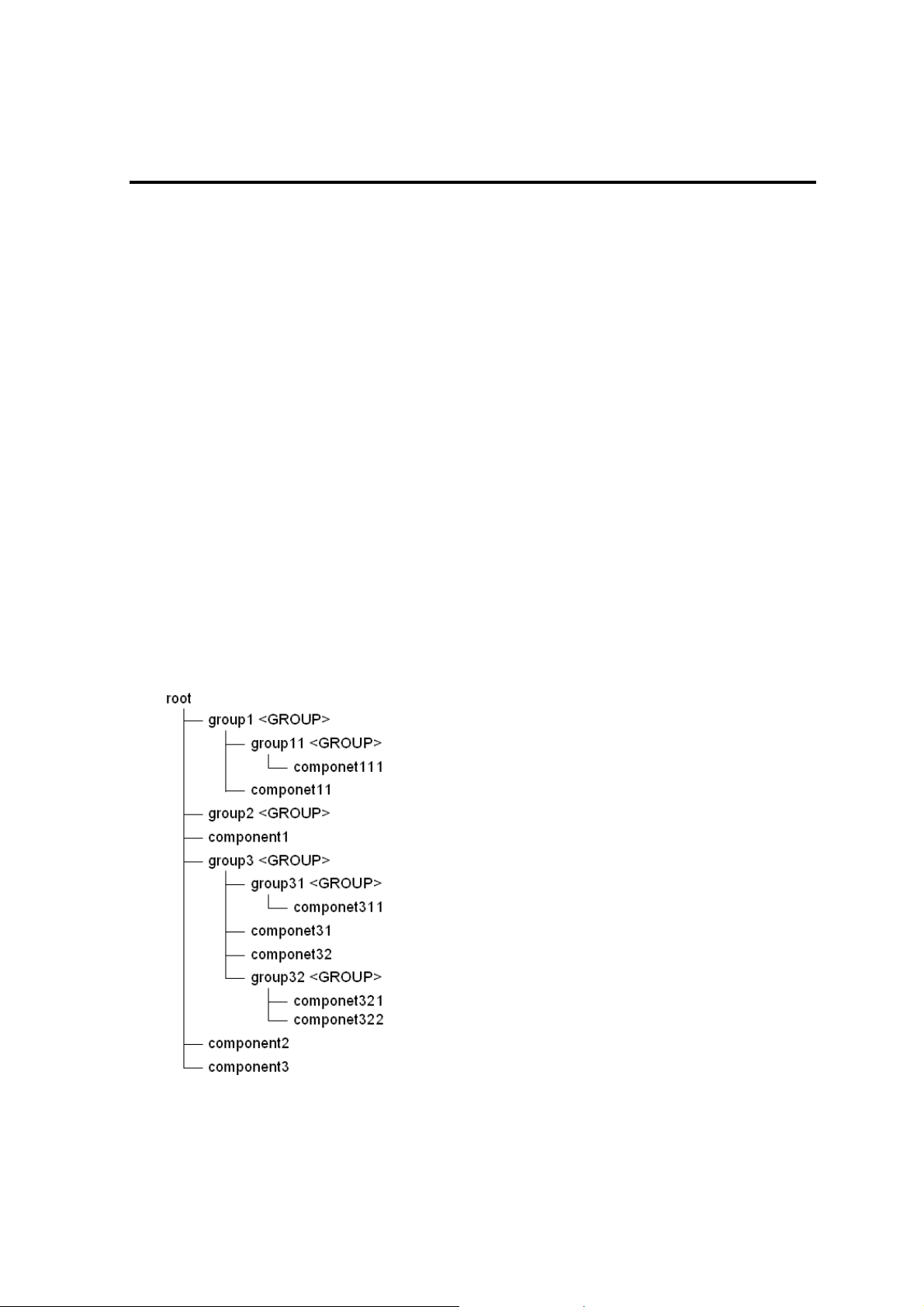
Display the list under the specified group and its sub-groups.
Output:
Shows the example that the groups and components have following structure.
9
Page 11

Displays the list of groups and components. The following shows an example.
>dscli getList root
group1 <GROUP>
group2 <GROUP>
component1
group3 <GROUP>
component2
component3
Displays the case specified “/g” option. The following shows an example.
>dscli getList root /g
group1 <GROUP>
group2 <GROUP>
group3 <GROUP>
Displays the case specified “/x” option. The following shows an example.
>dscli getList root /x
root
group1 <GROUP>
group11 <GROUP>
component111
component11
group2 <GROUP>
component1
group3 <GROUP>
group31 <GROUP>
component311
component31
component32
group32 <GROUP>
component321
component322
component2
component3
Displays the case specified “/g” and “/x” option. The following shows an example.
>dscli getList root /g /x
root
group1 <GROUP>
group11 <GROUP>
group2 <GROUP>
group3 <GROUP>
group31 <GROUP>
group32 <GROUP>
10
Page 12

2.1.2 createGroup
Syntax:
dscli createGroup GroupName [ParentGroupName]
Description:
Creates a new component group.
Options:
GroupName
Specify the group name to create. You can input up to 63 characters.
ParentGroupName
Specify the name of the parent group when the group is made under the group.
If you create a group under root, specify “root” or omit this option.
TIP:
The name of group that is already registered cannot be specified to GroupName
2.1.3 deleteGroup
Syntax:
dscli deleteGroup GroupName
Description:
Deletes a specified group. All managed components and sub-groups in the group are also deleted.
Options:
GroupName
Specify the name of the group.
2.1.4 moveGroup
Syntax:
dscli moveGroup GroupName [ParentGroupName]
Description:
Move the specified group. All managed components and sub-groups in the group are also moved
Options:
GroupName
Specify the name of group.
ParentGroupName
Specify the name of the parent group to move to.
If you move the group under root, specify “root” or omit this option.
11
Page 13

2.1.5 setGroupProperty
Syntax:
dscli setGroupProperty GroupName PropertyName Value
Description:
Sets the property of a group.
Options:
GroupName
Specify the name of group.
PropertyName
Specify the name of the group property. The following is group property list:
Value
Specify a new value to be set. See the list below.
PropertyName Contents Value Default
GROUP_NAME
GROUP_COMMENT
Specify the name of the group. Up to 63
characters.
Enter the comments of the group. Up to 255
characters.
(None)
(None)
TIP:
The name of group that is already registered cannot be specified to GROUP_NAME.
2.1.6 getGroupProperty
Syntax:
dscli getGroupProperty GroupName PropertyName
Description:
Displays the property of a group.
Options:
GroupName
Specify the name of group.
PropertyName
Specify the name of group property. For the list of group properties, see the 2.1.5 setGroupProperty
command
Output:
Display the property of a group.
12
Page 14

2.1.7 getGroupStatus
Syntax:
dscli getGroupStatus GroupName
Description:
Displays the status of a specified component group. Among all component condition under the group,
displays the worst condition as a status of the group.
Confirms the condition of component by component monitoring function.
Options:
GroupName
Specify the name of group.
Output:
Displays the status of the specified component group. There are following types of status.
ERROR Error
WARNING Warning
UNKNOWN Unknown or connection error
DC-OFF DC-OFF
NORMAL Normal
NO_MONITORING Out of monitoring
13
Page 15

2.1.8 groupPowerOn
Syntax:
dscli groupPowerOn GroupName [/p] [/exs ComponentName1 ComponentName2 ...
ComponentNameN] [/exg GroupName1 GroupName2 ... GroupNameN]
Description:
Turns on all managed components in a specified group.
The managed components in the sub-group are also controlled.
IMPORTANT:
In case that the managed component does not sup port a force network-boo t function which
boots the component from network regardless of boot order, a force network-boot function
cannot be executed. See “NEC ESMPRO Manager Managed Components Summary”
whether the managed component supports function.
CHECK:
This command is not executed for the PowerBay, the EM card, and the switch blade.
Options:
GroupName
Specify the name of group.
If you want to control all the components under root, specify “root”.
/p
Force boot from network after the power is turned on.
/exs
When you specify “/exs” option and the component name after it, the command is not executed on the
specified component. You can specify plural component names.
/exg
When you specify “/exg” option and the group name after it, the command is not executed on the
component under the specified group. You can specify plural group names.
Output:
If error has occurred, the name and the error message about each error-occurred managed component is
displayed.
The following shows an example.
Component1
: Connection to the server could not be made. (Timeout)
Component2
: Connection to the server could not be made. (Authentication error)
14
Page 16

2.1.9 groupPowerOff
Syntax:
dscli groupPowerOff GroupName [/exs ComponentName1 ComponentName2 ...
ComponentNameN] [/exg GroupName1 GroupName2 ... GroupNameN]
Description:
Forcibly turns off all managed components in a specified group.
The managed components in the sub-group are also controlled.
IMPORTANT:
Since remote power control using NEC ESMPRO Manager is provided by hardware
regardless of the condition of operating system on the managed component, the system may
be damaged. Be careful when you perform remote power control. Reconfirm the status of
the managed component before power controls.
CHECK:
This command is not executed for the PowerBay, the EM card, and the switch blade.
Options:
GroupName
Specify the name of group.
If you want to control all the components under root, specify “root”.
/exs
When you specify “/exs” option and the component name after it, the command is not executed on the
specified component. You can specify plural component names.
/exg
When you specify “/exg” option and the group name after it, the command is not executed on the
component under the specified group. You can specify plural group names.
Output:
If error has occurred, the name and the error message about each error-occurred managed component is
displayed.
The following shows an example.
Component1
: Connection to the server could not be made. (Timeout)
Component2
: Connection to the server could not be made. (Authentication error)
15
Page 17

2.1.10 groupReset
Syntax:
dscli groupReset GroupName [/p] [/exs ComponentName1 ComponentName2 ...
ComponentNameN] [/exg GroupName1 GroupName2 ... GroupNameN]
Description:
Forcibly resets all managed components in a specified group.
The managed components in the sub-group are also controlled.
IMPORTANT:
Since remote power control using NEC ESMPRO Manager is provided by hardware
regardless of the condition of operating system on the managed component, the system may
be damaged. Be careful when you perform remote power control. Reconfirm the status of
the managed component before power controls.
In case that the managed component does not sup port a force network-boo t function which
boots the component from network regardless of boot order, a force network-boot function
cannot be executed. See “NEC ESMPRO Manager Managed Components Summary”
whether the managed component supports function.
CHECK:
This command is not executed for the PowerBay, the EM card, and the switch blade.
Options:
GroupName
Specify the name of group.
If you want to control all the components under root, specify “root”.
/p
Force boot from network after reset.
/exs
When you specify “/exs” option and the component name after it, the command is not executed on the
specified component. You can specify plural component names.
/exg
When you specify “/exg” option and the group name after it, the command is not executed on the
component under the specified group. You can specify plural group names.
Output:
If error has occurred, the name and the error message about each error-occurred managed component is
displayed.
The following shows an example.
Component1
: Connection to the server could not be made. (Timeout)
Component2
: Connection to the server could not be made. (Authentication error)
16
Page 18

2.1.11 groupPowerCycle
Syntax:
dscli groupPowerCycle GroupName [/p] [/exs ComponentName1 ComponentName2 ...
ComponentNameN] [/exg GroupName1 GroupName2 ... GroupNameN]
Description:
Forcibly turns off all managed components in a specified group and then turns them on.
The managed components in the sub-group are also controlled.
IMPORTANT:
Since remote power control using NEC ESMPRO Manager is provided by hardware
regardless of the condition of operating system on the managed component, the system may
be damaged. Be careful when you perform remote power control. Reconfirm the status of
the managed component before power controls.
In case that the managed component does not sup port a force network-boo t function which
boots the component from network regardless of boot order, a force network-boot function
cannot be executed. See “NEC ESMPRO Manager Managed Components Summary”
whether the managed component supports function.
CHECK:
This command is not executed for the PowerBay, the EM card, and the switch blade.
Options:
GroupName
Specify the name of group.
If you want to control all the components under root, specify “root”.
/p
Force boot from network after the power is turned on.
/exs
When you specify “/exs” option and the component name after it, the command is not executed on the
specified component. You can specify plural component names.
/exg
When you specify “/exg” option and the group name after it, the command is not executed on the
component under the specified group. You can specify plural group names.
Output:
If error has occurred, the name and the error message about each error-occurred managed component is
displayed.
The following shows an example.
Component1
: Connection to the server could not be made. (Timeout)
Component2
: Connection to the server could not be made. (Authentication error)
17
Page 19

2.1.12 groupShutdownOs
Syntax:
dscli groupShutdownOs GroupName [/force] [/exs ComponentName1
ComponentName2 ... ComponentNameN] [/exg GroupName1 GroupName2 ... GroupNameN]
Description:
Shut downs operating systems on all managed components in a specified group.
The managed components in the sub-group are also controlled.
This command via LAN instructs the NEC ESMPRO Agent Extension service to shutdown the operating
system.
If you specify “/force” option, this command executes the forced shutdown OS function without
communication to the NEC ESMPRO Agent Extension or the NEC ESMPRO Agent.
You need to specify “/force” option if the connection is via LAN or direct.
CHECK:
This command is not executed for the PowerBay, the EM card, and the switch blade.
Options:
GroupName
Specify the name of group.
If you want to control all the components under root, specify “root”.
/force
If you specify “/force” option, this command executes the forced shutdown OS function. This shutdown
may not work depending on the kind of OS or the OS settings.
/exs
When you specify “/exs” option and the component name after it, the command is not executed on the
specified component. You can specify plural component names.
/exg
When you specify “/exg” option and the group name after it, the command is not executed on the
component under the specified group. You can specify plural group names.
Output:
If error has occurred, the name and the error message about each error-occurred managed component is
displayed.
The following shows an example.
Component1
: Connection to the component could not be made. (Timeout)
Component2
: Connection to the component could not be made. (Authentication error)
18
Page 20

2.1.13 groupSetPowerRestoreDelay
Syntax:
dscli groupSetPowerRestoreDelay GroupName DelayTime [/x Policy] [/exs
ComponentName1 ComponentName2 ... ComponentNameN] [/exg GroupName1
GroupName2 ... GroupNameN]
Description:
Changes the power option that specifies working of managed components in a specified group when they are
turned AC ON.
The managed components in the sub-group are also controlled.
The power option includes AC-LINK policy and the time that delays Power ON (DC ON) when the managed
component is set to be turned DC ON in time with AC ON.
IMPORTANT:
In case that the managed component does not support a setting of power restore delay, this
command is invalid. See “NEC ESMPRO Manager Managed Components Summary”
whether the managed component supports the function.
CHECK:
This command is not executed for the PowerBay, the EM card, and the switch blade.
NEC ESMPRO Manager does not set the specified delay time to the blade server in which
EXPRESSSCOPE Engine 3 is integrated.
Options:
GroupName
Specify the name of group.
If you want to control all the components under root, specify “root”.
DelayTime
AAA–600 Set the delay time from turning on AC to turning on DC.
* AAA is the minimum value of the delay time of the components.
-1 Set “-1” if you do not change the delay time from turning on AC to turning on DC.
RANDOM Set “RANDOM” if you change the delay time from turning on AC to turning on DC to
random setting.
* If the component supports random setting, the random setting can be specified.
/x Policy
Set AC-Link policy. There are 3 types of the policy.
STAY_OFF The managed component remains OFF when AC power is restored.
LAST_STATE If the managed component is OFF when AC power is lost, the managed component
remains OFF when AC power is restored.
If the managed component is ON, when AC power is lost, the managed component
turns ON after the delay time when AC power is restored.
POWER_ON The managed component turns ON after the delay time when AC power is restored.
/exs
When you specify “/exs” option and the component name after it, the command is not executed on the
specified component. You can specify plural component names.
/exg
When you specify “/exg” option and the group name after it, the command is not executed on the
component under the specified group. You can specify plural group names.
19
Page 21

Output:
If error has occurred, the name and the error message about each error-occurred managed component is
displayed.
The following shows an example.
Component1
: Connection to the component could not be made. (Timeout)
Component2
: Connection to the component could not be made. (Authentication error)
2.1.14 getGroupRemoteKvmLicense
Syntax:
dscli getGroupRemoteKvmLicense GroupName
Description:
Displays the state of “Remote KVM and Media License” for each managed components in a specified group.
The managed components in the sub-group are also displayed.
Options:
GroupName
Specify the name of group.
If you want to control all the components under root, specify “root”.
Output:
The following are states of “Remote KVM and Media License”.
Installed “Remote KVM and Media License” has been installed.
Not Installed “Remote KVM and Media License” has not been installed.
Unsupported “Remote KVM and Media License” is not supported for the component.
- The state of “Remote KVM and Media License” is unknown.
The following shows an example.
Component1
: Installed
Component2
: Installed
Component3
: Not Installed
Component4
: Unsupported
Component5
: :
:
20
Page 22

2.2 Component Management Commands
2.2.1 getServerList
Syntax:
dscli getServerList [/d]
Description:
Displays the name list of all managed components registered on NEC ESMPRO Manager.
Options:
/d
If you specify “/d” option, the managed components list will indicate component name, GUID and
MAC address of LAN port that BMC uses of each component. Added information below is also
indicated.
EXPRESSSCOPE Engine series BMC is EXPRESSSCOPE Engine series.
ARMC : BMC is Advanced Remote Management Card.
SWB : indicates that the managed component is a kind of switch blade.
Output:
Displays the name list of all managed components registered on NEC ESMPRO Manager. The following
shows an example.
If “/d” option is not specified:
Component1
Component2
Component3
:
:
If “/d” option is specified:
Component1
GUID 02010202:0000:0000:0000:000000000000
MAC1 00:30:13:f1:00:5a
MAC2 00:30:13:f1:00:5b
EXPRESSSCOPE Engine
Component2
GUID 00301316:cdfe:0180:0010:846e8062d906
MAC1 00:30:13:16:cd:fe
SWB
Component3
GUID 00010203:0405:0607:0809:0a0b0c0d0e0f
MAC1 00:00:4c:9f:13:cb
ARMC
:
:
21
Page 23

2.2.2 getServerNameByMacAddr
Syntax:
dscli getServerNameByMacAddr MacAddress
Description:
Displays the name of the managed component that has the specified MAC address.
Options:
MacAddress
Specify a MAC address of LAN port that BMC uses on the managed component.
The following shows an example.
dscli getServerNameByMacAddr 00:30:13:f1:00:5a
Output:
Displays the name of the managed component. The following shows an example.
Component1
2.2.3 getServerNameByGuid
Syntax:
dscli getServerNameByGuid GUID
Description:
Displays the name of the managed component that has the specified GUID.
Options:
GUID
Specify a GUID.
The following shows an example.
dscli getServerNameByGuid 00301316:cdfe:0180:0010:846e8062d906
Output:
Displays the name of the managed component. The following shows an example.
Component2
22
Page 24

2.2.4 findNewServer
Syntax:
dscli findNewServer StartIpAddr EndIpAddr
Description:
Finds BMC on managed components that are not registered on NEC ESMPRO Manager according to IP
address range specification.
TIP:
To register the managed component that is found using findNewServer command or
findNewServerNetAddr command, you can use createServer command. See 2.2.6
createServer.
Options:
StartIpAddr
Specify the start address of IP address range.
EndIpAddr
Specify the end address of IP address range.
Output:
Displays the list of the found managed components. The following shows an example.
Status: SUCCESS
No.1
1st IP Address : 192.168.14.18
2nd IP Address : 0.0.0.0
Current IP Address : 192.168.14.18
IPMI Version : 1.5
GUID : 84ee20b0:84a1:d511:0080:a0ff94470300
No.2
1st IP Address : 192.168.14.19
2nd IP Address : 0.0.0.0
Current IP Address : 192.168.14.19
IPMI Version : 1.5
GUID : 00004c79:45c0:0180:0010:f57f80d8cef8
:
:
23
Page 25

2.2.5 findNewServerNetAddr
Syntax:
dscli findNewServerNetAddr NetAddr NetMask
Description:
Finds BMC on managed components that are not registered on NEC ESMPRO Manager according to
Network address specification.
TIP:
To register the managed component that is found using findNewComponent command or
findNewServerNetAddr command, you can use createServer command. See 2.2.6
createServer.
Options:
NetAddr
Specify network address.
NetMask
Specify network mask.
Output:
Displays the list of the found managed components same as the output by “f indNewServer ” command. See
2.2.4 findNewServer.
2.2.6 createServer
Syntax:
dscli createServer ComponentName GroupName AuthKey [IpAddr1] [IpAddr2]
Description:
Newly registers a managed component on the NEC ESMPRO Manager.
Options:
ComponentName
Specify the name of the managed component. You can input up to 63 characters.
GroupName
Specify the name of group that the managed component belongs to.
AuthKey
Specify the authentication key that is configured on BMC. You can input up to 16 characters.
IpAddr1
IpAddr2
Specify the IP address of the managed component's BMC. This option is omissible if you control the
managed component via modem or with direct connection.
Specify the extra IP address of the managed component's BMC. This option is omissible.
TIPS:
The name of component that is already registered cannot be specified to ComponentName.
The IP address that is already registered cannot be specified to IpAddr1and IpAddr2.
Set other properties using 2.2.9 setServerProperty command.
24
Page 26

2.2.7 deleteServer
Syntax:
dscli deleteServer Component [/force]
Description:
Deletes the specified managed component that is registered on the NEC ESMPRO Manager.
Options:
Component
Specify the name, the MAC address of LAN port that BMC uses, or the GUID of the managed
component.
/force
When you delete the managed component that has been set schedule runn ing, the schedule is deleted
from NEC ESMPRO Agent Extension. But if the schedule deletion is failed (such as NEC ESMPRO
Agent Extension is uninstalled), the component cannot be deleted. In this case you can specify “/force ”
option to delete component forcibly.
2.2.8 checkConnection
Syntax:
dscli checkConnection Component [/force]
Description:
Confirms connection with BMC on a managed component. This command also collects information for
remote control of the managed component.
Options:
Component
Specify the name, the MAC address of LAN port that BMC uses, or the GUID of the managed
component.
/force
Execute the command with "/force" option if the managed component is replaced.
TIP:
If NEC ESMPRO Manager Ver.5 manage NEC ESMPRO Manager Ver.4, and the “/force”
option is specified, NEC ESMPRO Manager Ver.5 may connect with different component
in communication with NEC ESMPRO Manager Ver.4 and BMC communicati on.
25
Page 27

2.2.9 setServerProperty
Syntax:
dscli setComponentProperty Component PropertyName Value
Description:
Sets the property of a managed component.
Options:
Component
Specify the name, the MAC address of LAN port that BMC uses, or the GUID of the managed
component.
PropertyName
Specify the name of the property. The following is property list:
Value
Specify new value to be set. See the list below.
PropertyName Contents Value Default
0: Disabled
1: Enabled
4 - 1000 64
0: Disabled
1: Enabled
0: Disabled
1: Enabled
Up to 20
characters
Up to 63
characters.
Up to 16
characters
0: LAN
1: Direct
2: Modem
IP address
format
IP address
format
IP address
format
CONSOLE_LOG_ENABLE
CONSOLE_LOG_SIZE
CONSOLE_LOG_KEEP_CONN
ECTION
CONSOLE_LOG_FAULT_MESS
AGE_MONITORING
CONSOLE_LOG_FAULT_MESS
AGE_IDENTIFIER
SERVER_NAME *1
SERVER_AUTHKEY *1
SERVER_CURRENT_PORT_T
YPE
SERVER_IP_1 *1
SERVER_IP_2
SERVER_CURRENT_IP *1
Determine whether to
enable/disable the get console log
function to save the Remote
Console screen data in text
format.
Specify the maximum size (in KB)
of the console log.
Determine whether to get console
log even while remote console is
not open on web browser.
Determine whether to
enable/disable the fault message
monitoring function that set fault
condition when a fault message
string is found on head of each
console log line.
Specify the character string for the
fault message monitoring function.
Specify the name of the managed
component.
Specify the authentication key to
communicate with BMC of the
managed component.
Specify the connection type
between the NEC ESMPRO
Manager component and the
managed component. Only LAN
can be specified for the EM card.
Specify BMC IP address to
communicate via LAN.
Specify extra BMC IP address to
communicate via LAN.
Specify current BMC IP address
to communicate via LAN.
1
0
1
</BP>
(None)
(None)
0
0.0.0.0
0.0.0.0
0.0.0.0
26
Page 28

PropertyName Contents Value Default
SERVER_SUBNETMASK_1 *1
SERVER_SUBNETMASK_2
SERVER_PHONE_NUMBER
SERVER_ALIAS *1
Specify subnet mask of the BMC
IP address.
Specify subnet mask of the extra
BMC IP address.
Specify the phone number to
communicate via modem.
Specify the alias of the managed
component.
IP address
format
IP address
format
Up to 19
characters
Up to 255 bytes (Same
*1 The property can be also set for an EM card.
TIPS:
The name of component that is already registered cannot be specified to SERVER_NAME.
The IP address that is already registered cannot be specified to SERVER_IP_1 and
SERVER_IP_2.
You can use moveServer command to change group that the managed component belongs
to. See 2.2.10.
2.2.10 moveServer
Syntax:
dscli moveServer Component GroupName
Description:
Changes the group that a managed component belongs to.
Options:
Component
Specify the name, the MAC address of LAN port that BMC uses, or the GUID of the managed
component.
GroupName
Specify the name of new group.
If you want to move the component under root, specify “root”.
255.255
.255.0
255.255
.255.0
(Blank)
as
compon
ent
name)
27
Page 29

2.2.11 getServerGroup
Syntax:
dscli getServerGroup Component
Description:
Display the name of group that a managed component belongs to.
Options:
Component
Specify the name, the MAC address of LAN port that BMC uses, or the GUID of the managed
component.
Output:
Display the name of group that the managed component belongs to.
If it belongs to root, displays “root”.
2.2.12 setCurrentPort
Syntax:
dscli setCurrentPort Component Connection
Description:
Changes the connection type between the NEC ESMPRO Manager component and a managed component.
Options:
Component
Specify the name, the MAC address of LAN port that BMC uses, or the GUID of the managed
component.
Connection
Specify the connection type between the NEC ESMPRO Manager component and the managed
component.
LAN Connects via LAN
SERIAL Connects directly to serial port
MODEM Connects via modem
28
Page 30

2.2.13 getServerProperty
Syntax:
dscli getServerProperty Component PropertyName
Description:
Displays the specified property of a managed component.
Options:
Component
Specify the name, the MAC address of LAN port that BMC uses, or the GUID of the managed
component.
PropertyName
Specify the name of component property. For the list of component properties, see the 2.2.9
setServerProperty command.
Output:
Displays the specified property of a managed component.
2.2.14 getServerInfo
Syntax:
dscli getComponentInfo Component
Description:
Displays the managed component information that includes main component properties.
Options:
Component
Specify the name, the MAC address of LAN port that BMC uses, or the GUID of the managed
component.
Output:
Displays the managed component information. The following information is shown:
Item Name Contents
Component Name Name of the managed component
Alias Alias of the managed component
Group Name of the group that the managed component belongs to.
Connection Type Connection type between the managed component and the NEC ESM PRO
BMC Control Display BMC management status
Check Connection Display “Completed” if the Check connection has been executed.
BMC Current IP Address Current BMC IP address to connect to the managed component via LAN.
Failover Determine whether to enable/disable the Fail over function that continues
BMC LAN1 IP Address BMC IP address to connect to the managed component via LAN.
BMC LAN1 Subnet Mask Subn et mask of the BMC IP address
Manager component.
Enable : management is valid
Disable : management is invalid
Not Registered : not registered for management
Not Support : out of management (BMC is not integrated)
communication by changing to the other IP address if communication with the
current BMC IP address encounters an error.
29
Page 31

BMC LAN2 IP Address Extra BMC IP address to connect to the managed component via LAN.
BMC LAN2 Subnet Mask Subnet mask of the extra BMC IP address
Phone Number Phone number of the managed component
Product Name Product name of the managed component
Serial Number Serial number of the managed component
GUID ID for identifying the managed component
IPMI Version IPMI version that the managed component supports
Remote KVM and
Media License
Chassis Name Name of chassis in which the managed component is installed. This item is
Slot Number Slot number of the blade slot in which the managed component is installed.
Blade Width Blade width with the occupied slot count. This item is shown If the managed
Blade Height Blade Height with the occupied slot count. This item is shown If the managed
Blade Name Blade name. This item is shown if the managed component has the name.
State of "Remote KVM and Media License" of the managed component. If this
managed component does not contain EXPRESSSCOPE Engine series, this
item is not shown. See 2.1.14”getGroupRemoteKvmLicense” for details.
shown If the managed component is CPU blade or switch blade.
This item is shown If the managed component is CPU blade or switch blade.
component is CPU blade or switch blade.
component is CPU blade or switch blade.
30
Page 32

2.2.15 getDeviceId
Syntax:
dscli getDeviceId Component
Description:
Obtains management controller information of the managed component.
Options:
Component
Specify the name, the MAC address of LAN port that BMC uses, or the GUID of the managed
component.
Output:
Displays management controller information. The following shows an example.
Device ID : 20H
Device Rev. : 1
Fw Rev. : 00.08
Manufacturer ID : 119
Product ID : 2c3H
2.2.16 getGuid
Syntax:
dscli getGuid Component
Description:
Obtains GUID of a managed component. GUID is ID for identifying a managed component.
Options:
Component
Specify the name, the MAC address of LAN port that BMC uses, or the GUID of the managed
component.
Output:
Displays GUID.
31
Page 33

2.2.17 getProductName
Syntax:
dscli getProductName Component
Description:
Obtains the product name and serial number of a managed component.
Options:
Component
Specify the name, the MAC address of LAN port that BMC uses, or the GUID of the managed
component.
Output:
Displays the following information.
ProductName product name of the managed component.
SerialNumber serial number of the managed component.
2.2.18 getSoftwareInfo
Syntax:
dscli getSoftwareInfo Component
Description:
Obtains version information about NEC ESMPRO Agent Extension, operating system and BIOS on the
managed component.
This command can be used via LAN when NEC ESMPRO Agent Extension service is running on the
managed component.
Options:
Component
Specify the name, the MAC address of LAN port that BMC uses, or the GUID of the managed
component.
Output:
Displays version information. The following shows an exa mple.
Agent Extension Version : 2.03.04
BIOS Version : 6.0.0106
OS Version : Windows 2003 Server
32
Page 34

2.2.19 setShutdownPolicy
Syntax:
dscli setShutdownPolicy Component KeyName Value
Description:
Changes shutdown policy of NEC ESMPRO Agent Extension on a managed component.
This command can be used via LAN when NEC ESMPRO Agent Extension service is running on the
managed component.
Options:
Component
Specify the name, the MAC address of LAN port that BMC uses, or the GUID of the managed
component.
KeyName
Specify a key name to be set. See the list below.
Value
Specify a new value to be set. See the list below.
KeyName Contents Value
SCH_ACLINK_STAYON_ENABLE Determine whether to
enable/disable the function that
changes AC-LINK policy
to ”Always Power On” when “OS
shutdown” is executed through
“scheduled running”
SCH_AC_LINK Specify AC-LINK Policy.
(This setting works like as
setPowerRestoreDelay
command.)
* Display only. Cannot be set.
SCH_DC_OFF_ENABLE Determine whether to
enable/disable the function that
turns the managed component
off forcibly after shutdown OS.
If the managed component is still
DC-ON state after OS shutdown,
set enable to turn it off when
NEC ESMPRO Agent Extension
shutdowns its OS.
SCH_DC_OFF_DELAY Specify delay time in minutes to
turn the managed component off
after shutdown OS.
This setting is effective only when
SCH_DC_OFF_ENABLE is
enabled.
SCH_SHUTDOWN_ENABLE
Determine whether to
enable/disable the function which
shutdowns OS when the
managed component is turned on
during the down period specified
through “scheduled running”.
0: Disabled
1: Enabled
-
0: Disabled
1: Enabled
5-60
0: Disabled
1: Enabled
33
Page 35

KeyName Contents Value
SCH_SHUTDOWN_WAIT Specify delay time in seconds to
shutdown the managed
component after shutdown OS
command is issued.
* Display only. Cannot be set.
-
2.2.20 getShutdownPolicy
Syntax:
dscli getShutdownPolicy Component
Description:
Obtains shutdown policy of NEC ESMPRO Agent Extension on a managed component.
This command can be used via LAN when NEC ESMPRO Agent Extension service is running on the
managed component.
Options:
Component
Specify the name, the MAC address of LAN port that BMC uses, or the GUID of the managed
component.
Output:
Displays shutdown policy. For details, see 2.2.19.
The following shows an example.
SCH_ACLINK_STAYON_ENABLE=0
SCH_AC_LINK=1
SCH_DC_OFF_ENABLE=1
SCH_DC_OFF_DELAY=10
SCH_SHUTDOWN_ENABLE=1
SCH_SHUTDOWN_WAIT=60
34
Page 36

2.2.21 setPowerRestoreDelay
Syntax:
dscli setPowerRestoreDelay Component DelayTime [/x Policy]
Description:
Changes the power option that specifies working of a managed component when it is turned AC ON.
The power option includes AC-LINK policy and the time that delays Power ON (DC ON) when the managed
component is set to be turned DC ON in time with AC ON.
IMPORTANT:
In case that the managed component does not support a setting of power restore delay, This
command is invalid. See “NEC ESMPRO Manager Managed Components Summary”
whether the managed component supports the function.
CHECK:
NEC ESMPRO Manager does not set the specified delay time to the blade server in which
EXPRESSSCOPE Engine 3 is integrated.
Options:
Component
Specify the name, the MAC address of LAN port that BMC uses, or the GUID of the managed
component.
DelayTime
AAA – BBB Set the delay time from turning on AC to turning on DC.
* AAA is the minimum value of the delay time of the components.
* If the component is EXPRESSSCOPE Engine 3, BBB is 600.
* If the component is not EXPRESSSCOPE Engine 3, BBB is 255.
-1 Set “-1” if you do not change the delay time from turning on AC to turning on DC.
RANDOM Set “RANDOM” if you change the delay time from turning on AC to turning on DC to
random setting.
* If the component supports random setting, the random setting can be specified.
/x Policy
Set AC-Link policy. There are 3 types of the policy.
STAY_OFF The managed component remains OFF when AC power is restored.
LAST_STATE If the managed component is OFF when AC power is lost, the managed component
remains OFF when AC power is restored.
If the managed component is turned AC OFF during it is in DC ON, the managed
component is turned DC ON after the delay time when it is turned AC ON.
POWER_ON The managed component is turned DC ON after the delay time when it is turned A C
ON.
35
Page 37

2.2.22 getPowerRestoreDelay
Syntax:
dscli getPowerRestoreDelay Component
Description:
Obtains power option that specifies working of a managed component when it is turned AC ON.
For details, see 2.2.21 setPowerRestoreDelay.
Options:
Component
Specify the name, the MAC address of LAN port that BMC uses, or the GUID of the managed
component.
Output:
Display power option information. The following shows an example.
Policy : LAST_STATE
Delay Time : RANDOM
Delay Time Range : 45 - 600 sec
2.2.23 setBmcInfo
Syntax:
dscli setBmcInfo Component KeyName Value [/x ModuleNo]
Description:
Changes BMC configuration information on the managed component. The parameter supported according to
the kind of BMC is different.
TIPS:
Use setAuthKey command to change authentication key or password of PPP server. See
2.2.25 setAuthKey.
Use setSensorLevel command to change separate sensor level. See 2.2.26 setSensorLevel.
CFG_NETWORK_SHARED_BMC_LAN,CFG_NETWORK_BMC_MAC,
CFG_NETWORK_GUID cannot be specified fo r setBmcInfo command. Specify those for
getBmcInfo command. See 2.2.24 getBmcInfo.
Options:
Component
Specify the name, the MAC address of LAN port that BMC uses, or the GUID of the managed
component.
KeyName
Specify the key name of BMC configuration. See the list below.
Value
Specify the new values to be set. See the list below.
36
Page 38

/x ModuleNo
Specify the CPU/IO module number (0 or 1) if the managed component is a fault tolerant server. This
parameter is valid for the network items.
For network items, this command changes the setting of the CPU/IO module 0 if you omit this
parameter for the fault tolerant server.
For the other items, this command changes the setting of both CPU/IO modules regardless of the
parameter.
Specify the Master BMC(0) or Standby BMC(1) if the managed component is the server which has
EXPRESSSCOPE Engine SP3 (2BMC model). This option is valid for network configurations.
For network property items, this command changes the setting of the Master BMC(0) if you omit this
parameter for the server which has EXPRESSSCOPE Engine SP3 (2BMC model).
KeyName Contents Value
CFG_COMPUTER_NAME Common:
Computer Name
CFG_COMMUNITY Common:
Community Name
CFG_ALERT_ALL Common: Alert 0: Disabled
CFG_POLICY Common: Alert Policy 1: One Alert
CFG_ALERT_ACKNOWLEDGE Common:Alert Acknowledge 0: Disabled
CFG_ALERT_LEVEL Common: Alert Level 0: no Alert
CFG_LAN_CONTROL_LAN1 Common:
Remote Control (LAN1)
CFG_SERIAL_CONTROL Common:
Remote Control
(WAN/Direct)
CFG_LAN_REDIRECTION Common:
Redirection (LAN)
CFG_SERIAL_REDIRECTION Common:
Redirection (WAN/Direct)
CFG_LAN_CONTROL_LAN2 Common:
Remote Control (LAN2)
CFG_LAN_ALERT_POLICY_LAN Common:
LAN1 / LAN2 priority
CFG_LAN_ALERT_POLICY_DESTINATION Common:
LAN / Alert Receiver priority
CFG_DHCP LAN1:
Obtain an IP Address
automatically(DHCP)
CFG_LAN_IP_LAN1 LAN1:
IP Address
CFG_LAN_SUBNET_LAN1 LAN1:
Subnet Mask
CFG_LAN_GATEWAY_LAN1 LAN1:
Default Gateway
CFG_LAN_MANAGE1_ALERT_LAN1 LAN1:
Alert Receiver/ management
PC(1) Alert
Up to 15 characters
Up to 16 characters
1: Enabled
Destination
2: All Alert Destination
1: Enabled
1-6: Alert Level 1-6
0: Disabled
1: Enabled
0: Disabled
1: Enabled
0: Disabled
1: Enabled
0: Disabled
1: Enabled
0: Disabled
1: Enabled
0: LAN1
1: LAN2
0: LAN Channel
1: Alert Receiver
0: Disabled
1: Enabled
IP address format
IP address format
IP address format
0: Disabled
1: Enabled
37
Page 39

KeyName Contents Value
CFG_LAN_MANAGE1_IP_LAN1 LAN1:
Alert Receiver/ management
PC(1) IP address
CFG_LAN_MANAGE2_ALERT_LAN1 LAN1:
Alert Receiver/ management
PC(2) Alert
CFG_LAN_MANAGE2_IP_LAN1 LAN1:
Alert Receiver/ management
PC(2) IP address
CFG_LAN_MANAGE3_ALERT_LAN1 LAN1:
Alert Receiver/ management
PC(3) Alert
CFG_LAN_MANAGE3_IP_LAN1 LAN1:
Alert Receiver/ management
PC(3) IP address
CFG_LAN_ALERT_RETRY_COUNT_LAN1 LAN1:
Alert Retry Count
CFG_LAN_ALERT_RETRY_TIMEOUT_LAN1 LAN1: Alert Timeout (in
seconds)
CFG_DHCP_LAN2 LAN2:
Obtain an IP Address
automatically(DHCP)
CFG_LAN_IP_LAN2 LAN2:
IP Address
CFG_LAN_SUBNET_LAN2 LAN2:
Subnet Mask
CFG_LAN_GATEWAY_LAN2 LAN2:
Default Gateway
CFG_LAN_MANAGE1_ALERT_LAN2 LAN2:
Alert Receiver/ management
PC (1) Alert
CFG_LAN_MANAGE1_IP_LAN2 LAN2:
Alert Receiver/ management
PC (1) IP address
CFG_LAN_MANAGE2_ALERT_LAN2 LAN2:
Alert Receiver/ management
PC (2) Alert
CFG_LAN_MANAGE2_IP_LAN2 LAN2:
Alert Receiver/ management
PC (2) IP address
CFG_LAN_MANAGE3_ALERT_LAN2 LAN2:
Alert Receiver/ management
PC (3) Alert
CFG_LAN_MANAGE3_IP_LAN2 LAN2:
Alert Receiver/ management
PC (3) IP address
CFG_LAN_ALERT_RETRY_COUNT_LAN2 LAN2:
Alert Retry Count
CFG_LAN_ALERT_RETRY_TIMEOUT_LAN2 LAN2:
Alert Timeout (in seconds)
CFG_SERIAL_MODE WAN/Direct: Mode 1: Direct
IP address format
0: Disabled
1: Enabled
IP address format
0: Disabled
1: Enabled
IP address format
0 - 7
3 - 30
0: Disabled
1: Enabled
IP address format
IP address format
IP address format
0: Disabled
1: Enabled
IP address format
0: Disabled
1: Enabled
IP address format
0: Disabled
1: Enabled
IP address format
0 – 7
3 – 30
2: Modem
38
Page 40

KeyName Contents Value
CFG_SERIAL_BAUDRATE WAN/Direct: Baud Rate 1: 9600bps
CFG_SERIAL_FLOW_CONTROL WAN/Direct
Flow Control
CFG_SERIAL_DIAL_MODE WAN/Direct
Dial Mode
CFG_SERIAL_INIT WAN/Direct
Initial Command
CFG_SERIAL_HANG_UP WAN/Direct
Hang-up Command
CFG_SERIAL_DTR_HANG_UP WAN/Direct
DTR Hang-up
CFG_SERIAL_ESCAPE_CODE WAN/Direct
Escape Code
CFG_SERIAL_DIAL_RETRY_COUNT WAN/Direct
Dial retry count
CFG_SERIAL_DIAL_RETRY_INTERVAL WAN/Direct
Dial retry interval (in
seconds)
CFG_SERIAL_ALERT_RETRY_COUNT WAN/Direct
Alert retry count
CFG_SERIAL_ALERT_RETRY_INTERVAL WAN/Direct
Alert timeout Interval (in
seconds)
CFG_SERIAL_ALERT_PPP1 WAN/Direct
Primary PPP component
Alert
CFG_SERIAL_DIAL_NUMBER_PPP1 WAN/Direct
Primary PPP component
Phone Number
CFG_SERIAL_USER_ID_PPP1 WAN/Direct
Primary PPP component
User ID
CFG_SERIAL_DOMAIN_PPP1 WAN/Direct
Primary PPP component
Domain
CFG_SERIAL_ALERT_PPP2 WAN/Direct
Secondary PPP component
Alert
CFG_SERIAL_DIAL_NUMBER_PPP2 WAN/Direct
Secondary PPP component
Phone Number
CFG_SERIAL_USER_ID_PPP2 WAN/Direct
Secondary PPP component
User ID
CFG_SERIAL_DOMAIN_PPP2 WAN/Direct
Secondary PPP component
Domain
CFG_SERIAL_MANAGE1_IP WAN/Direct
Alert Receiver (1)
IP address
2: 19.2Kbps
3: 57.6Kbps
4: 115.2Kbps
1: None
2: RTS/CTS
3: XON/XOFF
1: Pulse
2: Tone
Up to 48 characters
Up to 8 characters
0: Disabled
1: Enabled
1character
0 – 7
60 – 240
0 – 7
3 – 30
0: Disabled
1: Enabled
Up to 19 characters
Up to 16 characters
Up to 16 characters
0: Disabled
1: Enabled
Up to 19 characters
Up to 16 characters
Up to 16 characters
IP address format
39
Page 41

KeyName Contents Value
CFG_SERIAL_MANAGE2_IP WAN/Direct
Alert Receiver (2)
IP address
CFG_SERIAL_MANAGE3_IP WAN/Direct
Alert Receiver (3)
IP address
CFG_PAGER_MANAGE1_ALERT Pager:
Alert Receiver (1) Alert
CFG_PAGER_MANAGE1_DIAL_NUMBER Pager:
Alert Receiver (1) Phone
Number
CFG_PAGER_MANAGE2_ALERT Pager:
Alert Receiver (2) Alert
CFG_PAGER_MANAGE2_DIAL_NUMBER Pager:
Alert Receiver (2) Phone
Number
CFG_PAGER_MESSAGE Pager:
Pager message
CFG_PAGER_TIMEOUT Pager:
Guide Message Waiting
Time (2 seconds unit)
CFG_NETWORK_SHARED_BMC_LAN Network
Property:
Management LAN
Management LAN Port
CFG_NETWORK_CONNECTION_TYPE Network
Property:
Basic Connection Type
CFG_NETWORK_BMC_MAC Network
Property:
BMC MAC Address
CFG_NETWORK_DHCP Network
Property:
Basic DHCP
CFG_NETWORK_IP_LAN Network
Property:
Basic IP Address
CFG_NETWORK_SUBNET_LAN Network
Property:
Basic Subnet Mask
CFG_NETWORK_GATEWAY_LAN Network
Property:
Basic Default Gateway
CFG_NETWORK_DYNAMIC_DNS Network
Property:
Basic Dynamic DNS
IP address format
IP address format
0: Disabled
1: Enabled
Up to 19 characters
0: Disabled
1: Enabled
Up to 19 characters
Up to 29 characters
0-30
0:Management LAN
1:Shared System LAN
0: Auto Negotiation
1: 100Mbps Full
Duplex
2: 100Mbps Half
Duplex
3: 10Mbps Full
Duplex
4: 10Mbps Half
Duplex
5: 1Gbps Full Duplex
6: 1Gbps Half Duplex
MAC address format
0: Disabled
1: Enabled
IP address format
IP address format
IP address format
0: Disabled
1: Enabled
40
Page 42

KeyName Contents Value
CFG_NETWORK_DNS_SERVER Network
Property:
Basic DNS Server
CFG_NETWORK_HOST_NAME Network
Property:
Basic Host Name
CFG_NETWORK_DOMAIN_NAME Network
Property:
Basic Domain Name
CFG_NETWORK_GUID Network
Property:
Basic System GUID
CFG_NETWORK_ACCESS_LIMITATION_TY
PE
CFG_NETWORK_ACCESS_ADDRESS Network
CFG_NETWORK_HTTP Network
CFG_NETWORK_HTTP_PORT Network
CFG_NETWORK_HTTPS Network
CFG_NETWORK_HTTPS_PORT Network
CFG_NETWORK_SSH Network
CFG_NETWORK_SSH_PORT Network
CFG_MAIL_ALERT Alert
CFG_MAIL_ALERT_TIMEOUT Alert
Network
Property:
Access Limitation Access
Limitation Type
Property:
Access Limitation IP
Address
Service:
Web Server
HTTP
Service:
Web Server
HTTP Port
Service:
Web Server
HTTPS
Service:
Web Server
HTTPS Port
Service:
SSH Interface SSH
Service:
SSH Interface SSH Port
Mail Alert:
Alert
Mail Alert:
Response time of SMTP
server
IP address format
Up to total of 254
characters of Host
Name and Domain
Name
Up to total of 254
characters of Host
Name and Domain
Name
0: Allow All
1: Allow Address
2: Deny Address
IP address format
Please delimit Internet
Protocol address by
using comma
The wildcard (*) can
be used in IP
address.
0: Disabled
1: Enabled
1 - 65535
0: Disabled
1: Enabled
1 - 65535
0: Disabled
1: Enabled
1 - 65535
0: Disabled
1: Enabled
30 - 600
41
Page 43

KeyName Contents Value
CFG_MAIL_ALERT_SERVER Alert
Mail Alert:
SMTP Server
SMTP Server
CFG_MAIL_ALERT_PORT Alert
Mail Alert:
SMTP Server
SMTP Port
CFG_MAIL_ALERT_CRAMMD5 Alert
Mail Alert:
SMTP Server
SMTP Authentication
CRAM-MD5
CFG_MAIL_ALERT_LOGIN Alert
Mail Alert:
SMTP Server
SMTP Authentication
LOGIN
CFG_MAIL_ALERT_PLAIN Alert
Mail Alert:
SMTP Server
SMTP Authentication
PLAIN
CFG_MAIL_ALERT_USER Alert
Mail Alert:
SMTP Server
User Name
CFG_MAIL_ALERT_TO1 Alert
Mail Alert:
Mail To1
Mail To1 Address
CFG_MAIL_ALERT_TO2 Alert
Mail Alert:
Mail To2
Mail To2 Address
CFG_MAIL_ALERT_TO3 Alert
Mail Alert:
Mail To3
Mail To3 Address
CFG_MAIL_ALERT_FROM Alert
Mail Alert:
Mail From
CFG_MAIL_ALERT_REPLY Alert
Mail Alert:
Mail Reply-To
CFG_MAIL_ALERT_SUBJECT Alert
Mail Alert:
Mail Subject
CFG_MAIL_ALERT_LEVEL Alert
Mail Alert:
Alert Level
Up to 255 characters
1 - 65535
0: Disabled
1: Enabled
0: Disabled
1: Enabled
0: Disabled
1: Enabled
Up to 64characters
Up to 255 characters
Please specify 0
when Mail Alert is
disabled.
Up to 255 characters
Please specify 0
when Mail Alert is
disabled.
Up to 255 characters
Please specify 0
when Mail Alert is
disabled.
Up to 255 characters
Up to 255 characters
Up to 63characters
0: Error
1: Error, Warning
2: Error, Warning,
Information
3: Separate setting
42
Page 44

KeyName Contents Value
CFG_SNMP_ALERT Alert
SNMP Alert:
Alert
CFG_SNMP_COMPUTER_NAME Alert
SNMP Alert:
Computer Name
CFG_SNMP_COMMUNITY Alert
SNMP Alert:
Community Name
CFG_SNMP_ALERT_ACKNOWLEDGE Alert
SNMP Alert:
Alert Acknowledge
CFG_SNMP_ALERT_POLICY Alert
SNMP Alert:
Alert Process
CFG_SNMP_ALERT_RETRY_COUNT Alert
SNMP Alert:
Alert Retry Count
CFG_SNMP_ALERT_TIMEOUT Alert
SNMP Alert:
Alert Timeout
CFG_SNMP_MANAGE1_ALERT Alert
SNMP Alert:
Alert Receiver Primary Alert
CFG_SNMP_MANAGE1_IP Alert
SNMP Alert:
Alert Receiver Primary IP
Address
CFG_SNMP_MANAGE2_ALERT Alert
SNMP Alert:
Alert Receiver Secondary
Alert
CFG_SNMP_MANAGE2_IP Alert
SNMP Alert:
Alert Receiver Secondary IP
Address
CFG_SNMP_MANAGE3_ALERT Alert
SNMP Alert:
Alert Receiver Tertiary Alert
CFG_SNMP_MANAGE3_IP Alert
SNMP Alert:
Alert Receiver Tertiary IP
Address
CFG_SNMP_ALERT_LEVEL Alert
SNMP Alert:
Alert Level
CFG_MISCELLANEOUS_SEL Other:
SEL
Behavior when SEL
repository is full
0: Disabled
1: Enabled
Up to 16characters
Up to 16characters
0: Disabled
1: Enabled
1:
One Alert
Receiver
2: All Alert Receivers
0 – 7
3 - 30
0: Disabled
1: Enabled
IP address format
0: Disabled
1: Enabled
IP address format
0: Disabled
1: Enabled
IP address format
0: Error
1: Error, Warning
2: Error, Warning,
Information
3: Separate setting
0: Stop logging SEL
1: Clear all SEL
2: Overwrite oldest
SEL
43
Page 45

KeyName Contents Value
CFG_MISCELLANEOUS_PEF Other:
Platform Event Filter
Platform Event Filter
0: Disabled
1: Enabled
44
Page 46

2.2.24 getBmcInfo
Syntax:
dscli getBmcInfo Component [/x ModuleNo]
Description:
Obtains BMC configuration information of a specified managed component.
Options:
Component
Specify the name, the MAC address of LAN port that BMC uses, or the GUID of the managed
component.
/x ModuleNo
Specify the CPU/IO module number (0 or 1) if the managed component is a fault tolerant server. This
parameter is valid for the network items.
For the network items, this command obtains the setting of the CPU/IO module 0 if you omit this
parameter for the fault tolerant server.
For the other items, this command obtains the setting of the current primary CPU/IO module regardless
of the parameter.
Specify the Master BMC(0) or Standby BMC(1) if the managed component is the server which has
EXPRESSSCOPE Engine SP3 (2BMC model). This option is valid for network configurations.
For the network property items, this command obtains the setting of the Master BMC(0) if you omit
this parameter for the server which has EXPRESSSCOPE Engine SP3 (2BMC model).
Output:
Displays BMC configuration information. See 2.2.23 setBmcInfo for details.
The following shows an example.
CFG_COMPUTER_NAME=Component1
CFG_COMMUNITY=public
CFG_ALERT_ALL=1
CFG_POLICY=1
CFG_ALERT_ACKNOWLEDGE=1
CFG_ALERT_LEVEL=4
CFG_LAN_REDIRECTION=1
CFG_LAN_CONTROL_LAN1=1
CFG_SERIAL_REDIRECTION=1
CFG_SERIAL_CONTROL=1
CFG_LAN_IP_LAN1=192.168.14.14
CFG_LAN_SUBNET_LAN1=255.255.255.0
CFG_LAN_GATEWAY_LAN1=192.168.14.1
CFG_LAN_MANAGE1_ALERT_LAN1=0
CFG_LAN_MANAGE1_IP_LAN1=0.0.0.0
CFG_LAN_MANAGE2_ALERT_LAN1=0
CFG_LAN_MANAGE2_IP_LAN1=0.0.0.0
CFG_LAN_MANAGE3_ALERT_LAN1=0
CFG_LAN_MANAGE3_IP_LAN1=0.0.0.0
CFG_LAN_ALERT_RETRY_COUNT_LAN1=3
CFG_LAN_ALERT_RETRY_TIMEOUT_LAN1=6
:
:
45
Page 47

2.2.25 setAuthKey
Syntax:
dscli setAuthKey Component OldPassword NewPassword SelectAuthKey
Description:
Changes the authentication key, PPP server’s password or SMTP server’s password of a BMC configuration.
The parameter supported according to the kind of BMC is different.
TIP:
After you succeed to change authentication key, you should change the authentication key
registered on NEC ESMPRO Manager using setComponentProperty command. See 2.2.9
setServerProperty.
Options:
Component
Specify the name, the MAC address of LAN port that BMC uses, or the GUID of the managed
component.
OldPassword
Specify current pas sword.
NewPassword
Specify new authentication key or PPP sever’s password up to 16 characters.
Specify new SMTP server’s password up to 20 characters.
SelectAuthKey
Specify a type of password.
0 Authentication key
1 Password of primary PPP server
2 Password of secondary PPP server
3 Password of SMTP server
2.2.26 setSensorLevel
Syntax:
dscli setSensorLevel Component Type SensorName Level1 Level2 Level3
Description:
Changes separate setting at the alert level of BMC configuration information on the manag ed component.
This command can be used when alert Level is only a separate setting.
TIP:
Use setBmcInfo command to change alert level to the separate setting of component. See
2.2.23setBmcInfo.
8 is not use. Use getSensorLevel command. See 2.2.27 getSensorLevel.
Options:
Component
Specify the name, the MAC address of LAN port that BMC uses, or the GUID of the managed
component.
46
Page 48

Type
Specify an alert type.
SNMP: SNMP alert
MAIL: MAIL alert
SensorName
Specify the key name of sensor. See the following list.
Level1
Specify the alert level of error.
Level2
Specify the alert level of warning.
Level3
Specify the alert level of information.
0: Disable to change SNMP alert or MAIL alert of alert level
1: Enable to change SNMP alert or MAIL alert to1 of alert level
2: Enable to change MAIL alert to2 of alert level
3: Enable to change MAIL alert to3 of alert level
4: Enable to change MAIL alert to1 or MAIL alert to2 of alert level
5: Enable to change MAIL alert to1 or MAIL alert to3 of alert level
6: Enable to change MAIL alert to2 or MAIL alert to3 of alert level
7: Enable to change MAIL alert to1,
MAIL alert to2 or MAIL alert to3 of alert level
8: SNMP alert and MAIL alert of unalterable alert level
TIP:
0 is specified for a unalterable alert level.
See the following list.
OK : Enable to change, NG : Disable to change
SensorName Contents Level1 Level2 Level3
TEMP_THRESHOLD Temperature
(Monitoring
Threshold)
VOLT_THRESHOLD Voltage (Monitoring
Threshold)
FAN_SENSOR FAN(Speed) OK OK OK
COOL_DEV_THRESHOLD Cooling Device
(Monitoring
Threshold)
TEMP_ABNORMAL Temperature
(Monitoring Abnormal
State)
POST_MEM_RESIZE POST Memory
Resize
MODULE_BOARD Module/Board(Missin
g)
SMI_TIMEOUT SMI Timeout OK NG OK
VOL_ABNORMAL Voltage (Monitoring
Abnormal State)
OK OK OK
OK OK OK
OK OK OK
OK NG OK
NG OK OK
OK NG OK
OK NG OK
47
Page 49

SensorName Contents Level1 Level2 Level3
COOL_DEV_ABNORMAL Cooling Device
(Monitoring Abnormal
State)
TRANSITION_PW_SAVE Transition to Power
Save
MICROCONTROLL_STS Microcontroller State NG OK OK
PW_UNIT_REDUN Power Unit
Redundancy
PHY_SEC Physical
Security(Chassis
Intrusion)
PLATFORM_SEC Platform Security
Violation Attempt
PROCESSOR Processor OK NG OK
PW_SUPPLY Power Supply NG OK OK
PW_UNIT_STS Power Unit State OK OK OK
MEM Memory OK NG OK
DRIVE_SLOT Drive Slot(Bay) OK OK OK
POST_ERR POST OK NG OK
EVT_LOG_DISABLED Event Logging NG OK OK
SYS_EVT System Event NG NG OK
CRITICAL_INT Critical Interrupt OK NG OK
BUTTON_SWITCH Button/Switch NG NG OK
CHIP_SET Chip Set OK NG OK
CABLE_INTERRUPT Cable/Interconnect NG NG OK
SYS_BOOT_RESTART_INIT System Boot/Restart
Initiated
BOOT_ERR Boot Error NG NG OK
OS_BOOT OS Boot NG NG OK
OS_STOP_SHUTDOWN OS Stop/Shutdown OK NG OK
SLOT_CONNECTOR Slot/Connector OK OK OK
ACPI System ACPI Power
State
WATCHDOG_TIMER Watchdog Timer OK NG OK
ENTITY_PRESENCE_INFO Entity Presence
Information
VERSION_CHANGE Version Change NG NG OK
FRU_HOT_SWAP FRU Hot Swap NG NG OK
SYS_SPEC_PW_STATE System Specific
Power State
PW_CAPPING Power Capping OK OK NG
SENSOR_FAILURE Sensor Failure OK NG OK
MANAGEMENT_ENGINE Management Engine OK OK *1 OK
OK OK OK
NG NG OK
OK OK OK
NG NG OK
NG NG OK
NG NG OK
NG NG OK
NG NG OK
NG NG OK
*1 Some models of managed servers may not support.
48
Page 50

See the following list for a fault tolerant server.
OK : Enable to change, NG : Disable to change
SensorName Contents Level1 Level2 Level3
TEMP_THRESHOLD Temperature
(Monitoring
Threshold)
VOLT_THRESHOLD Voltage (Monitoring
Threshold)
FAN_SENSOR FAN(Speed) NG OK OK
PROCESSOR Processor NG OK OK
PW_SUPPLY Power Supply NG OK OK
PW_UNIT_STS Power Unit State NG NG OK
MEM Memory NG OK OK
POST_ERR POST NG OK OK
EVT_LOG_DISABLED Event Logging NG NG OK
SYS_EVT System Event NG NG OK
CRITICAL_INT Critical Interrupt OK NG OK
BUTTON_SWITCH Button/Switch NG NG OK
SYS_BOOT_RESTART_INIT System Boot/Restart
Initiated
BOOT_ERR Boot Error NG NG OK
SLOT_CONNECTOR Slot/Connector NG NG OK
ACPI System ACPI Power
State
WATCHDOG_TIMER Watchdog Timer NG OK OK
SENSOR_FAILURE Sensor Failure NG OK OK
HA EVENT HA Event OK OK OK
NG OK OK
NG OK OK
NG NG OK
NG NG OK
See the following list for the server which has EXPRESSSCOPE Engine SP3 (2BMC model).
OK : Enable to change, NG : Disable to change
SensorName Contents Level1 Level2 Level3
TEMP_THRESHOLD Temperature( Monitori
ng Threshold)
VOLT_THRESHOLD Voltage(Monitoring
Threshold)
FAN_SENSOR FAN(Speed) OK OK OK
POST_MEM_RESIZE POST Memory
Resize
SMI_TIMEOUT SMI Timeout OK OK OK
VOL_ABNORMAL Voltage (Monitoring
Abnormal State)
PROCESSOR_ABNORMAL Processor(Monitoring
Abnormal State)
MODULE_BOARD_ABNORMAL Module/Board(Monitor
ing Abnormal State)
MODULE_BOARD_DISABLED Module/Board(Monitor
ing Disabled State)
SLOT_CONNECTOR_DISABLED Slot/Connector(Monit
oring Disabled State)
OK OK OK
OK OK OK
NG OK OK
OK OK OK
OK OK OK
OK NG OK
NG NG OK
OK OK OK
49
Page 51

SensorName Contents Level1 Level2 Level3
PROCESSOR_DEGRADED Processor(Monitoring
Degraded State)
MODULE_BOARD_DEGRADED Module/Board(Monitor
ing Degraded State)
MICROCONTROLL_STS Microcontroller State OK OK OK
SLOT_CONNECTOR_DEGRADED Slot/Connector(Monit
oring Degraded State)
FAN_REDUN FAN Redundancy OK NG OK
MEM_REDUN Memory Redundancy OK OK OK
PW_UNIT_REDUN Power Unit
Redundancy
PLATFORM_SEC Platform Security
Violation Attempt
PROCESSOR Processor OK OK OK
PW_SUPPLY Power Supply OK OK OK
PW_UNIT_STS Power Unit State OK OK OK
MEM Memory OK OK OK
DRIVE_SLOT Drive Slot(Bay) OK NG OK
POST_ERR POST NG NG OK
EVT_LOG_DISABLED Event Logging NG NG OK
SYS_EVT System Event OK NG OK
CRITICAL_INT Critical Interrupt OK OK OK
BUTTON_SWITCH Button/Switch NG NG OK
CHIP_SET Chip Set OK OK OK
SYS_BOOT_RESTART_INIT System Boot/Restart
Initiated
BOOT_ERR Boot Error NG NG OK
OS_BOOT OS Boot NG OK OK
OS_STOP_SHUTDOWN OS Stop/Shutdown NG NG OK
SLOT_CONNECTOR Slot/Connector OK OK OK
ACPI System ACPI Power
State
WATCHDOG_TIMER Watchdog Timer NG OK NG
ENTITY_PRESENCE_INFO Entity Presence
Information
BATTERY Battery OK OK OK
SYS_SPEC_PW_STATE System Specific
Power State
PW_CAPPING Power Capping NG OK NG
SENSOR_FAILURE Sensor Failure OK OK OK
MANAGEMENT_ENGINE Management Engine OK OK OK
NG NG OK
NG NG OK
OK OK OK
OK OK OK
NG NG OK
NG NG OK
NG NG OK
OK OK OK
OK OK OK
50
Page 52

2.2.27 getSensorLevel
Syntax:
dscli getSensorLevel Component Type
Description:
Obtains separate setting at the alert level of BMC configuration information of a specified managed
component.
Options:
Component
Specify the name, the MAC address of LAN port that BMC uses, or the GUID of the managed
component.
Type
Specify an alert type.
SNMP: SNMP alert
MAIL: MAIL alert
Output:
Displays alert level of BMC configuration information. See 2.2.26 setSensorLevel for details.
The following shows an example.
TEMP_THRESHOLD=111
VOLT_THRESHOLD=000
FAN_SENSOR=000
PLATFORM_SEC=800
PROCESSOR=000
PW_SUPPLY=000
PW_UNIT_STS=000
MEM=000
DRIVE_SLOT=000
EVT_LOG_DISABLED=800
SYS_EVT=080
CRITICAL_INT=000
BUTTON_SWITCH=880
MODULE_BOARD=800
SYS_BOOT_RESTART_INIT=880
BOOT_ERR=880
ACPI=880
SMI_TIMEOUT=800
POST_MEM_RESIZE=800
POST_ERR=800
SLOT_CONNECTOR=080
WATCHDOG_TIMER=080
SENSOR_FAILTURE=800
:
51
Page 53

2.2.28 getAgentExtensionLog
Syntax:
dscli getAgentExtensionLog Component
Description:
Obtains the application logs of the NEC ESMPRO Agent Extension on a managed component. This
command can be used via LAN when NEC ESMPRO Agent Extension service is running on the managed
component.
Options:
Component
Specify the name, the MAC address of LAN port that BMC uses, or the GUID of the managed
component.
Output:
Displays the application logs of the NEC ESMPRO Agent Extension.
52
Page 54

2.2.29 testAlert
Syntax:
dscli testAlert Component Target
Description:
Executes an alert test.
You can confirm the result of test using 2.2.30 getTestAlertStatus command. The parameter supported
according to the kind of BMC is different.
Options:
Component
Specify the name, the MAC address of LAN port that BMC uses, or the GUID of the managed
component.
Target
Specify an alert receiver.
LAN1_1 or 0: LAN1 alert receiver (1)
LAN1_2 or 1: LAN1 alert receiver (2)
LAN1_3 or 2: LAN1 alert receiver (3)
LAN2_1 or 3: LAN2 alert receiver (1)
LAN2_2 or 4: LAN2 alert receiver (2)
LAN2_3 or 5: LAN2 alert receiver (3)
PPP1_1 or 6: PPP1 alert receiver (1)
PPP1_2 or 7: PPP1 alert receiver (2)
PPP1_3 or 8: PPP1 alert receiver (3)
PPP2_1 or 9: PPP2 alert receiver (1)
PPP2_2 or 10: PPP2 alert receiver (2)
PPP2_3 or 11: PPP2 alert receiver (3)
Pager1 or 12: Pager alert receiver (1)
Pager2 or 13: Pager alert receiver (2)
SNMP1 or 14: SNMP alert receiver (1)
SNMP2 or 15: SNMP alert receiver (2)
SNMP3 or 16: SNMP alert receiver (3)
MAIL1 or 17: MAIL alert receiver (1)
MAIL2 or 18: MAIL alert receiver (2)
MAIL3 or 19: MAIL alert receiver (3)
53
Page 55

2.2.30 getTestAlertStatus
Syntax:
dscli getTestAlertStatus Component Target
Description:
Obtains the state of an alert test. The parameter supported according to the kind of BMC is different.
Options:
Component
Specify the name, the MAC address of LAN port that BMC uses, or the GUID of the managed
component.
Target
Specify an alert receiver. See 2.2.29 testAlert.
Output:
Displays the state of the alert test. One of the following test states is displayed.
TEST_UNKNOWN: Unknown status
TEST_TESTING: Now Alerting
TEST_SUCCESS: Alert test is succeeded.
TEST_ABORT: Alert test is failed.
TEST_CALL_FAILED: Alert test is failed. (Dial up error)
TEST_TIMEOUT: Alert test is failed. (Timeout)
TEST_ERROR: Alert test is failed (Other reason)
While an alert is being sent, the alert state is displayed as follows:
TEST_TESTING
2.2.31 getServerStatus
Syntax:
dscli getServerStatus Component
Description:
Displays the status of a specified managed component.
Confirms the managed component status by component monitoring function.
Options:
Component
Specify the name, the MAC address of LAN port that BMC uses, or the GUID of the managed
component.
Output:
Displays the managed component status as following.
ERROR: Error
WARNING: Warning
UNKNOWN: Unknown or connection error
DC-OFF: DC-OFF
NORMAL: Normal
NO_MONITORING: Out of monitoring
54
Page 56

2.2.32 getPowerStatus
Syntax:
dscli getPowerStatus Component
Description:
Obtains the power state of a specified managed component.
Options:
Component
Specify the name, the MAC address of LAN port that BMC uses, or the GUID of the managed
component.
Output:
Displays the power state of a specified managed component. There are the following power states:
DC-ON Power-ON
DC-OFF Power-OFF
2.2.33 getStatusLamp
Syntax:
dscli getStatusLamp Component
Description:
Obtains the state of a specified managed component STATUS lamp.
Obtains the state of system FAULT LED for a fault tolerant server.
Options:
Component
Specify the name, the MAC address of LAN port that BMC uses, or the GUID of the managed
component.
Output:
Displays the state of a specified managed component STATUS lamp. There are the following states of the
STATUS lamp
OFF Turn off.
GREEN_ON Turn on green.
GREEN_BLINK Blink green.
AMBER_ON Turn on amber.
AMBER_BLINK Blink amber
RED_ON Turn on red.
RED_BLINK Blink red.
55
Page 57

2.2.34 getPanelInfo
Syntax:
dscli getPanelInfo Component [/x ModuleNo]
Description:
Obtains the following state as the front panel information of a managed component: power state, the
STATUS lamp state, the displays of LCD, the system monitoring state of the watchdog timer, the counter of
power-on hours.
Options:
Component
Specify the name, the MAC address of LAN port that BMC uses, or the GUID of the managed
component.
/x ModuleNo
Specify the CPU/IO module number (0 or 1) if the managed component is a fault tolerant server.
If you omit this parameter for the fault tolerant server, this command obtains the state of the CPU/IO
module 0 for the network items.
Output:
Displays the front panel information. The following shows an example.
Power Status : S0_G0
STATUS Lamp : GREEN_ON
LCD0 : Prepare To Boot
LCD1 :
Watchdog Status : STARTED
Watchdog Use : SMS_OS
Watchdog Interval : 10 sec
POH : 262920 min
:
56
Page 58

2.2.35 powerOn
Syntax:
dscli powerOn Component [/p]
Description:
Turns on a specified managed component.
If the POWER switch needs to be pressed to recover the managed component from the sleep state, it can also
be recovered by executing this command.
IMPORTANT:
In case that the managed component does not sup port a force network-boo t function which
boots the component from network regardless of boot order, a force network-boot function
cannot be executed. See “NEC ESMPRO Manager Managed Components Summary”
whether the managed component supports function.
In the case of PowerBay, The power control is not performed to the powerbay. It is
performed to the maintenance card integrated on the PowerBay.
Options:
Component
Specify the name, the MAC address of LAN port that BMC uses, or the GUID of the managed
component.
/p
Force boot from network after the power is turned on.
2.2.36 powerOff
Syntax:
dscli powerOff Component
Description:
Forcibly turns off a specified managed component.
IMPORTANT:
Since remote power control using NEC ESMPRO Manager is provided by hardware
regardless of the condition of operating system on the managed component, the system may
be damaged. Be careful when you perform remote power control. Reconfirm the status of
the managed component before power controls.
In the case of PowerBay, The power control is not performed to the powerbay. It is
performed to the maintenance card integrated on the PowerBay.
Options:
Component
Specify the name, the MAC address of LAN port that BMC uses, or the GUID of the managed
component.
57
Page 59

2.2.37 reset
Syntax:
dscli reset Component [/p]
Description:
Forcibly resets a specified managed component.
IMPORTANT:
Since remote power control using NEC ESMPRO Manager is provided by hardware
regardless of the condition of operating system on the managed component, the system may
be damaged. Be careful when you perform remote power control. Reconfirm the status of
the managed component before power controls.
In case that the managed component does not sup port a force network-boo t function which
boots the component from network regardless of boot order, a force network-boot function
cannot be executed. See “NEC ESMPRO Manager Managed Components Summary”
whether the managed component supports function.
In the case of PowerBay, The power control is not performed to the powerbay. It is
performed to the maintenance card integrated on the PowerBay.
Options:
Component
Specify the name, the MAC address of LAN port that BMC uses, or the GUID of the managed
component.
/p
Force boot from network after reset.
58
Page 60

2.2.38 powerCycle
Syntax:
dscli powerCycle Component [/p]
Description:
Forcibly turns off a specified managed component and then turns it on.
IMPORTANT:
Since remote power control using NEC ESMPRO Manager is provided by hardware
regardless of the condition of operating system on the managed component, the system may
be damaged. Be careful when you perform remote power control. Reconfirm the status of
the managed component before power controls.
In case that the managed component does not sup port a force network-boo t function which
boots the component from network regardless of boot order, a force network-boot function
cannot be executed. See “NEC ESMPRO Manager Managed Components Summary”
whether the managed component supports function.
In the case of PowerBay, The power control is not performed to the powerbay. It is
performed to the maintenance card integrated on the PowerBay.
Options:
Component
Specify the name, the MAC address of LAN port that BMC uses, or the GUID of the managed
component.
/p
Force boot from network after the power is turned on.
59
Page 61

2.2.39 shutdownOs
Syntax:
dscli shutdownOs Component [/force]
Description:
Shut downs the operating system on a managed component.
This command via LAN instructs the NEC ESMPRO Agent Extension service to shutdown the operating
system. The command via modem or with direct connection instructs the NEC ESMPRO Agent.
If you specify “/force” option, this command executes the forced shutdown OS function without
communication to the NEC ESMPRO Agent Extension or the NEC ESMPRO Agent.
Options:
Component
Specify the name, the MAC address of LAN port that BMC uses, or the GUID of the managed
component.
/force
If you specify “/force” option, this command executes the forced shutdown OS function. This shutdown
may not work depending on the kind of OS or the OS settings.
2.2.40 dumpSwitch
Syntax:
dscli dumpSwitch Component
Description:
Pushes DUMP switch o n a managed component.
IMPORTANT:
Since remote power control using NEC ESMPRO Manager is provided by hardware
regardless of the condition of operating system on the managed component, the system may
be damaged. Be careful when you perform remote power control. Reconfirm the status of
the managed component before power controls.
Options:
Component
Specify the name, the MAC address of LAN port that BMC uses or the GUID of the managed
component.
60
Page 62

2.2.41 clearSel
Syntax:
dscli clearSel Component [/force]
Description:
Clears the System Event Log (SEL) area on a managed component.
Options:
Component
Specify the name, the MAC address of LAN port that BMC uses, or the GUID of the managed
component.
/force
If you specify “/force” option, this command clears the SEL area even while the automatic backup
service of NEC ESMPRO Agent is active on the managed component.
2.2.42 identifyChassis
Syntax:
dscli identifyChassis Component Period
Description:
Turns on the Unit ID lamp on a managed component.
Options:
Component
Specify the name, the MAC address of LAN port that BMC uses, or the GUID of the managed
component.
Period
Specify lamp-on period in seconds. You can specify 0 – 255.
2.2.43 getIpmiInfo
Syntax:
dscli getIpmiInfo Component FileName [/x ModuleNo]
Description:
Collects IPMI information and saves it as a specified file name.
If there is the type of information that is not read in but NEC ESMPRO Manager holds the previously read-in
information, the information is also saved in the file.
TIP:
You can display the IPMI information file on web browser interface of the NEC ESMPRO
Manager. Log in the NEC ESMPRO Manager and click the “Tools” on the header menu.
Options:
Component
Specify the name, the MAC address of LAN port that BMC uses, or the GUID of the managed
component.
61
Page 63

FileName
Specify the filename with path name for saving the IPMI information.
/x ModuleNo
Specify the CPU/IO module number (0 or 1) if the managed component is a fault tolerant server.
If you omit this parameter for the fault tolerant server, this command obtains the information of the
CPU/IO module 0.
2.2.44 getSensorList
Syntax:
dscli getSensorList Component [/x ModuleNo]
Description:
Creates a sensor list from the previously collected SDR of IPMI information through 2.2.43 getIpmiInfo
command and displays the list. The SDR record ID indicating each sensor is also displayed.
Options:
Component
Specify the name, the MAC address of LAN port that BMC uses, or the GUID of the managed
component.
/x ModuleNo
Specify the CPU/IO module number (0 or 1) if the managed component is a fault tolerant server.
If you omit this parameter for the fault tolerant server, this command obtains the information of the
CPU/IO module 0.
Output:
Displays the list of the sensor names. The following shows an ex ample.
0001h: Sensor Type=Temperature(Front Panel Temp), Owner=Basbrd Mgmt Ctlr
0002h: Sensor Type=Temperature(Baseboard Temp), Owner=Basbrd Mgmt Ctlr
0003h: Sensor Type=Temperature(Processor 1 Temp), Owner=Basbrd Mgmt Ctlr
0004h: Sensor Type=Temperature(Processor 2 Temp), Owner=Basbrd Mgmt Ctlr
0005h: Sensor Type=Temperature(PwrDstBd Temp), Owner=Basbrd Mgmt Ctlr
:
2.2.45 getSensorStatus
Syntax:
dscli getSensorStatus Component RecordId [/x ModuleNo]
Description:
Obtains the status of specified sensor on the managed component.
Options:
Component
Specify the name, the MAC address of LAN port that BMC uses, or the GUID of the managed
component.
RecordId
Specify the SDR record ID from the sensor list displayed by 2.2.44 getSensorList command.
62
Page 64

/x ModuleNo
Specify the CPU/IO module number (0 or 1) if the managed component is a fault tolerant server.
If you omit this parameter for the fault tolerant server, this command obtains the status of the CPU/IO
module 0.
Output:
Displays the status of the sensor. The following shows an example.
Current Value:
30.00 degrees C
Current Status:
Normal
Upper non-recoverable Threshold:
--Upper critical Threshold:
46.00 degrees C (Hysteresis:44.00 degrees C)
Upper non-critical Threshold:
43.00 degrees C (Hysteresis:41.00 degrees C)
Lower non-critical Threshold:
3.00 degrees C (Hysteresis:5.00 degrees C)
Lower critical Threshold:
0.00 degrees C (Hysteresis:2.00 degrees C)
Lower non-recoverable Threshold:
---
2.2.46 getConsoleLog
Syntax:
dscli getConsoleLog Component
Description:
Displays the console log of a specified component.
Options:
Component
Specify the name, the MAC address of LAN port that BMC uses, or the GUID of the managed
component.
Output:
Displays the console log of a specified component.
63
Page 65

2.2.47 setBmcIpSync
Syntax:
dscli setBmcIpSync Component Value
Description:
Changes BMC IP Address Synchronization of NEC ESMPRO Agent Extension on a managed component.
BMC IP Address Synchronization means the function that the NEC ESMPRO Agent Extension corrects the
IP address in the BMC configuration information periodically to the IP address set on the operating system if
the managed component contains the BMC that use standard LAN port.
This command can be used via LAN when NEC ESMPRO Agent Extension service is running on the
managed component.
Options:
Component
Specify the name, the MAC address of LAN port that BMC uses, or the GUID of the managed
component.
Value
Specify a new value to be set.
0 Disable
1 Enable
TIP:
If this command is sent to NEC ESMPRO Agent Extension on the managed component
that contains the BMC that uses an exclusive LAN port (Management LAN Port), the
command end successfully, but nothing is set.
2.2.48 getBmcIpSync
Syntax:
dscli getBmcIpSync Component
Description:
Obtains BMC IP Address Synchronization of NEC ESMPRO Agent Extension on a managed component.
BMC IP Address Synchronization means the function that the NEC ESMPRO Agent Extension corrects the
IP address in the BMC configuration information periodically to the IP address set on the operating system if
the managed component contains the BMC that use standard LAN port.
This command can be used via LAN when NEC ESMPRO Agent Extension service is running on the
managed component.
Options:
Component
Specify the name, the MAC address of LAN port that BMC uses, or the GUID of the managed
component.
Output:
Displays BMC IP Address Synchronization. The following shows an example.
Agent Config (BMC IP Sync) : Enable
64
Page 66

2.2.49 getBladeSlotId
Syntax:
dscli getBladeSlotId Component
Description:
Execute 2.2.41 getIpmiInfo command previously.
Obtains enclosure ID and slot ID of a managed component if the managed server is a blade. The enclosure ID
is for identifying the blade assembly unit where the blade is installed. The slot ID shows the installation
position inside the blade assembly unit where the slot is installed.
Options:
Component
Specify the name, the MAC address of LAN port that BMC uses, or the GUID of the managed
component.
Output:
Displays enclosure ID and slot ID. The following shows an example.
Enclosure ID: 0040000000
Slot ID: 2
2.2.50 deleteBmcUser
Syntax:
dscli deleteBmcUser Component UserId
Description:
Deletes the user account that is set in the BMC configuration of components
Options:
Component
Specify the name, the MAC address of LAN port that BMC uses, or the GUID of the managed
component.
UserId
Specify the number allocated to the BMC user.
65
Page 67

2.2.51 getBmcUserList
Syntax:
dscli getBmcUserList Component
Description:
Displays a list of user accounts that is set in the BMC configuration of components
Options:
Component
Specify the name, the MAC address of LAN port that BMC uses, or the GUID of the managed
component.
Output:
The following shows an example.
No.1
User : Enable
User Name : USERNAME1
Privilege : Administrator
No.2
User : Enable
User Name : USERNAME2
Privilege : Operator
No.3
User : Disable
User Name : USERNAME3
Privilege : User
66
Page 68

2.2.52 setBmcUserInfo
Syntax:
dscli setBmcUserInfo Component UserId KeyName Values
Description:
Changes the user account information for the BMC configuration
Options:
Component
Specify the name, the MAC address of LAN port that BMC uses, or the GUID of the managed
component.
UserId
Specify the number being allocated by user that uses BMC(1 – 12).
KeyBane
Specify the key name of BMC configuration. See the list below.
Value
Specify a new value to be set. See the list below.
KeyName Value
USER
USER_NAME Up to 15 characters(*1)
USER_PASSWORD Up to 19 characters(*2)
USER_PRIVILEGE
0: Disabled
1: Enabled
0: User
1: Operator
2: Administrator
(*1) Must be specified with half-size alphanumeric characters, '-'(minus sign) and '_'(underscore).
(*2) Only ASCII character string that excludes ' '(blank)', '"'(quotation marks)' and '=' can be used.
2.2.53 getBmcUserInfo
Syntax:
dscli getBmcUserInfo Component UserId
Description:
Gets the user account information for the BMC configuration
Options:
Component
Specify the name, the MAC address of LAN port that BMC uses, or the GUID of the managed
component.
UserId
Specify the number being allocated by user that uses BMC(1 – 12).
Output:
The following shows an example.
USER : true
USER NAME : USERNAME2
USER_PRIVILEGE : Operator
67
Page 69

2.2.54 setPowerRestorePolicy
Syntax:
dscli setPowerRestorePolicy Component Policy
Description:
Changes AC-Link policy that specifies working of a managed component when it is turned AC ON.
Options:
Component
Specify the name, the MAC address of LAN port that BMC uses, or the GUID of the managed
component.
Policy
Set AC-Link policy. There are 3 types of the policy.
STAY_OFF The managed component remains OFF when AC power is restored.
LAST_STATE If the managed component is OFF when AC power is lost, the managed component
remains OFF when AC power is restored.
If the managed component is turned AC OFF during it is in DC ON, the managed
component is turned DC ON after the delay time when it is turned AC ON.
POWER_ON The managed component is turned DC ON after the delay time when it is turned A C
ON.
2.2.55 getPowerRestorePolicy
Syntax:
dscli getPowerRestorePolicy Component
Description:
Obtains AC-Link policy that specifies working of a managed component when it is turned AC ON.
Options:
Component
Specify the name, the MAC address of LAN port that BMC uses, or the GUID of the managed
component.
Output:
The following shows an example.
Policy : STAY_OFF
68
Page 70

2.2.56 getSystemFtLamp
Syntax:
dscli getSystemFtLamp Component
Description:
Obtains the state of System FT LED if the managed component is a fault tolerant server.
Options:
Component
Specify the name, the MAC address of LAN port that BMC uses, or the GUID of the managed
component.
Output:
There are the following states of the System FT LED.
GREEN_OFF Power off or simplex
GREEN_ON Duplex
GREEN_BLINK Split mode.
69
Page 71

2.3 EM Card Management Commands
The following component management commands can be used for an EM card. However, the MAC address
cannot be specified for the option "Server".
getServerNameByGuid
findNewServer
findNewServerNetAddr
createServer
deleteServer
checkConnection
setServerProperty
getServerProperty
getServerInfo
getDeviceId
getGuid
getServerStatus
2.3.1 getEmCardList
Syntax:
dscli getEmCardList [/d]
Description:
Displays the name list of all EM cards registered on NEC ESMPRO Manager.
Options:
/d
If you specify “/d” option, the EM cards list indicates EM card name and GUID.
Output:
The following shows an example.
If “/d” option is not specified:
EM0001
EM0002
If “/d” option is specified:
EM0001
GUID 01b21dd2:1dd2:11b2:2fa4:003013630cc5
EM0002
GUID 01b21dd2:1dd2:11b2:49bd:003013630cc0
70
Page 72

2.3.2 getEmActiveState
Syntax:
dscli getEmActiveState EmCard
Description:
Displays state of active/standby of the specified EM card.
Options:
EmCard
Specify the name of EM card.
Output:
There are the following states of EM card
Active active
Standby standby
2.3.3 identifyEm
Syntax:
dscli identifyEm EmCard [/x SwmSlotNumber]
Description:
Turns on the Unit ID lamp of specified EM card or the switch module that is managed by the EM card for 15
seconds. Only when the EM card is active, this command is available.
Options:
EmCard
Specify the name of the EM card.
/x SwmSlotNumber
Specify the slot number of the switch module, when you want to turn on Unit ID lamp of the switch
module that is managed by the EM card.
71
Page 73

2.3.4 getEmStatusLamp
Syntax:
dscli getEmStatusLamp EmCard [/x SwmSlotNumber]
Description:
Obtains the state of a specified EM card or the switch module that is managed by the EM card. Only when
the EM card is active, this command is available.
Options:
EmCard
Specify the name of the EM card.
/x SwmSlotNumber
Specify the slot number of the switch module, when you want to obtain Status lamp of switch module
that is managed by the EM card.
Output:
There are the following states of the STATUS lamp
GREEN_ON Turn on green.
GREEN_BLINK Blink green.
AMBER_BLINK Blink amber.
RED_BLINK Blink red.
72
Page 74

2.4 Chassis Management Commands
2.4.1 getBladeEnclosureList
Syntax:
dscli getBladeEnclosureList
Description:
Displays the list of the blade enclosure in which the managed component or the EM card registered on NEC
ESMPRO Manager is installed.
Output:
Displays the list of the blade enclosure with the component or the EM card registered on NEC ESMPRO
Manager.
2.4.2 getChassisSlotState
Syntax:
dscli getChassisSlotState ChassisName
Description:
Displays the state of blade slots when the specified chassis is a blade enclosure. The list of the EM card and
the switch module are displayed if the EM card and the switch module are installed in chassis.
Options:
ChassisName
Specify the chassis name.
Output:
Following information is shown for each slot.
Contents Explanation
slot number Displays the slot number.
Displays two slot numbers when the installed blade has double wide or full height.
slot state
component name Displays the component name when the component is
installed in the slot and it is registered on NEC ESMPRO
Manager. For double wide blade, displays “(Double-wide)”
following the component name. For full height blade,
displays “(Full-height)” following the component name.
Installed Displays “Installed ” when the switch module is installed in
the slot.
Not registered Displays “Not registered” when the component is installed
in the slot and it is not registered on NEC ESMPRO
Manager.
Not installed Display “Not Installed” when nothing is installed in the slot.
(blank) Displays nothing if “Installed” and “Not Registered” cannot
be distinguished.
73
Page 75

The following shows an example.
CPU Blade:
1: SERVER_0001
2: SERVER_0002
3,4: SERVER_0003 (Double-wide)
5: Not installed
6: Not registered
7: Not installed
8: Not registered
EM Card:
1.EM0001
2.EM0002
Switch Module:
1: Installed
2: Installed
3: Not installed
4: Not installed
5: Not installed
6: Not installed
2.4.3 getChassisInfo
Syntax:
dscli getChassisInfo ChassisName
Description:
Displays information on the specified chassis.
Options:
ChassisName
Specify the chassis name.
Output:
Display information on the specified chassis.
Item Name Contents
Chassis Name Name of the chassis.
Comments Comments of the chassis
Rack Name Displays the rack name which is set on the EM card.
Rack ID Displays the rack id which is set on the EM card.
Unit Name Displays the unit name which is set on the EM card.
Serial Number Displa ys the chassis serial number of the blade enclosure.
74
Page 76

2.4.4 setChassisProperty
Syntax:
dscli setChassisProperty ChassisName PropertyName Value
Description:
Sets the chassis property of a chassis.
Options:
ChassisName
Specify the chassis name.
PropertyName
Specify the name of the chassis property. See the list below.
Value
Specify a new value to be set. See the list below.
PropertyName Contents Value
CHASSIS_NAME Specify the name of the chassis. Up to 32 characters.
CHASSIS COMMENT Enter the comments of the chassis. Up to 100 characters.
TIP:
The name of chassis that is already registered cannot be specified to ChassisName.
2.4.5 getChassisProperty
Syntax:
dscli getChassisProperty ChassisName PropertyName
Description:
Displays the property of the specified chassis.
Options:
ChassisName
Specify the chassis name.
PropertyName
Specify the name of chassis property. For the list of chassis properties, see the 2.4.4 setChassisProperty
command.
Output:
Display the property of a chassis.
75
Page 77

2.4.6 setBladeAutoSetting
Syntax:
dscli setBladeAutoSetting ChassisName SlotNumber PropertyName Value
Description:
This command is effective only to the chassis in which EM card can be installed.
If NEC ESMPRO Manger detects new CPU blade installed on the chassis, NEC ESMPRO Manager
configures BMC on the CPU blade (managed component) through the EM card to control the managed
component remotely.
Set information to perform the configuration of BMC on CPU blade and the component registration
automatically.
Options:
ChassisName
Specify the chassis name.
SlotNumber
Specify the slot number of CPU blade. When a common value to all slots is set, “all” is specified.
PropertyName
Specify the name of the chassis property. See the list below.
Value
Specify a new value to be set. See the list below.
PropertyName Contents Value
AUTH_KEY Specify the authentication key that is
configured on BMC.
RECONFIGURE_ BMC “Enabled" means that NEC ESMPEO
Manager executes BMC configuration not
only new installed CPU blade but also all
CPU blade. “Disabled” means that NEC
ESMPRO Manager executes BMC
configuration only if BMC on new installed
CPU blade has not been configured.
REWRITE_IP_ADDRE
SS
DHCP BMC automatically acquires IP address from
IP_ADDRESS Specify IP address set to CPU blade. When
SUBNET_MASK Specify the subnet mask. IP Address form
DEFAULT_GATEWAY Specify the default gateway. IP Address form
ALERT_RECEIVER_IP
_ADDRESS
IP address of the BMC on the CPU blade
may be obtained by DHCP even through the
BMC configuration has not been executed.
If this option is set “Enable”, NEC ESMPRO
Manager always update the IP address
when BMC configuration is executed.
DHCP.
you specify “all” for “SlotNumber” option, IP
address consecutive from specified IP
address is sequentially set from the first slot.
Specify the alert receiver(1)/IP address of
PC for management.
Up to 16 characters
0: Disabled
1: Enabled
0: Disabled
1: Enabled
0: Disabled
1: Enabled
IP Address form
IP Address form
76
Page 78

2.4.7 getBladeAutoSetting
Syntax:
dscli getBladeAutoSetting ChassisName SlotNumber
Description:
This command is effective only to the chassis that can install the EM card.
Display information to perform configuration of BMC of a CPU blade and component registration
automatically when NEC ESMPRO Manager detects new CPU blade installed on the chassis.
See 2.4.6 setBladeAutoSetting for each information details.
Options:
ChassisName
Specify the chassis name.
SlotNumber
Specify the slot number of CPU blade.
Output:
The following shows an example.
RECONFIGURE_BMC:Disable
REWRITE_IP_ADDRESS:Diasable
DHCP:Enable
ALERT_RECEIVER_IP_ADDRESS:192.168.14.18
77
Page 79

2.5 Communication Management Commands
2.5.1 connect
Syntax:
dscli connect Component
Description:
Connects to a managed component with via modem or with direct connection according to the connection
type of the component property.
Options:
Component
Specify the name, the MAC address of LAN port that BMC uses, or the GUID of the managed
component.
2.5.2 disconnect
Syntax:
dscli disconnect
Description:
Disconnects the currently connected line.
2.5.3 getConnectionStatus
Syntax:
dscli getConnectionStatus
Description:
Displays the status of the serial connection (via modem or wit h direct c on necti on ).
Output:
Displays the status of the serial connection. There are following status:
CONNECTING Now connecting.
CONNECTED Connection is complete.
DISCONNECTING Now disconnecting.
DISCONNECTED Disconnection is complete.
CONNECTION_FAILURE Failed to connect.
NO_CARRIER Line is disconnected.
BUSY Now talking.
NO_DIALTONE Cannot detect dialtone.
78
Page 80

2.6 Environment Setting Commands
2.6.1 setOption
Syntax:
dscli setOption OptionName Value
Description:
Sets an option of the NEC ESMPRO Manager.
Options:
OptionName
Specify a name of the NEC ESMPRO Manager option. See the list below.
Value
Specify new value to be set. See the list below.
OptionName Contents Value Default
Specify Retry count for
BMC_RETRY_COUNT
BMC_TIMEOUT
BMC_SOURCE_PORT
CUI_NO_RESPONSE_TI
MEOUT
CUI_SYS_RQ_KEY
HISTORY_LOG_NUMBER
_OF_RECORDS
MODEM_PORT_NUMBER
MONITORING_ENABLE
MONITORING_AUTO_UP
DATE_INTERVAL
RC_POWER_CONTROL_I
NTERVAL_MILLIS
RMI_PORT Specify a TCP port number for RMI. 1024 - 65535 1099
communicating to BMC on a
managed component.
Communication Timeout (in seconds)
to BMC on a managed component.
Specify a UDP port number for
communicating to BMC on a
managed component.
Specify times (in seconds) until the
remote console is disconnected due
to a communication timeout.
Specify alias for SysRq key on CUI
remote console.
Specify maximum number of
application logs.
Specify a serial port on NEC
ESMPRO Manager component.
The serial port is used for
communicating to the managed
component via modem or with direct
connection.
Determine whether to enable/disable
the component monitoring function
that monitors the power status and
the STATUS lamp on each managed
component.
Specify interval times (in seconds) to
update automatically the displays of
component status.
Specify interval times (in
milliseconds) at which power control
is performed continuously for multiple
components.
0-10 5
1-15 5
1025-65535 47117
20-1800 60
"": Not specified
"Q": Ctrl+Alt+Q
"X": Ctrl+Alt+X
2000-10000 2000
1-8 1
0: Disabled
1: Enabled
1-60 5
0-5000 500
“”
1
79
Page 81

2.6.2 getOption
Syntax:
dscli getOption OptionName
Description:
Displays an option of the NEC ESMPRO Manager.
Options:
OptionName
Specify a name of the NEC ESMPRO Manager option. See 2.6.1 setOption for option list.
Output:
Display the value of the specified option.
2.6.3 getPermitIpAddrList
Syntax:
dscli getPermitIpAddrList
Description:
Displays the IP address ranges in which login to NEC ESMPRO Manager is permitted.
Only the Web clients in this IP address ranges are possible to login to NEC ESMPRO Manager.
Output:
Displays the list of IP address ranges. The following shows an example.
No.1: 192.168.0.1 – 192.168.0.254
No.2: 192.168.1.10
No.3: 192.168.2.10
80
Page 82

2.6.4 isPermitIpAddr
Syntax:
dscli isPermitIpAddr CheckIpAddr
Description:
Checks whether a specified IP address is permitted for login from a Web client and displays the check result.
Options:
CheckIpAddr
Specify IP address.
Output:
Displays the result of IP address check.
OK means this IP address is permitted
NG means this IP address is not permitted.
2.6.5 addPermitIpAddr
Syntax:
dscli addPermitIpAddr StartIpAddr [EndIpAddr]
Description:
Adds an IP address range in which login to NEC ESMPRO Manager is permitted.
Only the Web clients in this IP address ranges are possible to login to NEC ESMPRO Manager.
TIP:
You can login to NEC ESMPRO Manager from a web browser on the component that NEC
ESMPRO Manager is installed even if the IP address is not permitted using this command.
Options:
StartIpAddr
Specify the start IP address of IP address range to permit login.
EndIpAddr
Specify the end IP address of IP address range. If this option is omitted, it will be permitted the single
IP address that is specified in the StartIAddr option.
2.6.6 removePermitIpAddr
Syntax:
dscli removePermitIpAddr StartIpAddr [EndIpAddr]
Description:
Removes IP address range in which login from a Web client is permitted.
Options:
StartIpAddr
Specify the start IP address of IP address range.
EndIpAddr
Specify the end IP address of IP address range.
81
Page 83

2.6.7 clearPermitIpAddr
Syntax:
dscli clearPermitIpAddr
Description:
Removes all IP address ranges in which login from a Web client is permitted.
82
Page 84

2.7 User Management Commands
2.7.1 createUser
Syntax:
dscli createUser UserName Password
Description:
Registers a new user that can login to the NEC ESMPRO Manager from web browser. The user level of the
user to be registered is “operator”. Up to 30 users can be created.
Options:
UserName
Specify a new user name. Up to 16 characters.
Password
Specify a login password for the new user. You can input the password with 6 - 16 letters.
TIP:
The name of user that is already registered cannot be specified to UserName.
2.7.2 deleteUser
Syntax:
dscli deleteUser UserName
Description:
Deletes a user that can login to the NEC ESMPRO Manager from web browser.
Options:
UserName
Specify a name of the user.
2.7.3 getUserList
Syntax:
dscli getUserList
Description:
Displays the list of registered user names and levels. “Administrator” or “Operator” is displayed as the user
level.
Output:
The following shows an example.
Admin Administrator
User1 Operator
User2 Operator
:
:
83
Page 85

2.7.4 setUserProperty
Syntax:
dscli setUserProperty UserName PropertyName Value
Description:
Sets a property of a specified user.
Options:
UserName
Specify a user name.
PropertyName
Specify a property name. See the list below.
It is valid for “Operator” level user to change the executable authority.
OK : Enable to change, NG : Disable to change
Value
Specify new value to be set. See the list below.
PropertyName Contents Value Default
USER_NAME
USER_PASSWORD
USER_COMMENT
UL_POWER_ON
UL_POWER_OFF
UL_RESET
UL_POWER_CYCLE
UL_SHUTDOWN
UL_DUMP
UL_SEL_CLEAR
UL_BMC_REMOTE
UL_CONFIG_CREATE
UL_CONFIG_CHANGE_
DELETE
UL_REMOTE_CONSOLE
UL_SCHEDULE
Specify the user name Up to 16
characters.
Specify the login password. 6-16
characters.
Specify the comment about the user. Up to 100
characters.
Specify the enable/disable of Power
ON.
Specify the enable/disable of Power
OFF function.
Specify the enable/disable of Reset
function.
Specify the enable/disable of Power
Cycle function.
Specify the enable/disable of
Shutdown OS function.
Specify the enable/disable of DUMP
switch function.
Specify the enable/disable of Clear
System Event Log function.
Specify the enable/disable of Change
BMC Configuration function.
Specify the enable/disable of Add
Component function.
Specify the enable/disable of Set
Component Property function and
Delete Component function.
Specify the enable/disable of Remote
Console function.
Specify the enable/disable of Set
Schedule function.
0: Disabled
1: Enabled
0: Disabled
1: Enabled
0: Disabled
1: Enabled
0: Disabled
1: Enabled
0: Disabled
1: Enabled
0: Disabled
1: Enabled
0: Disabled
1: Enabled
0: Disabled
1: Enabled
0: Disabled
1: Enabled
0: Disabled
1: Enabled
0: Disabled
1: Enabled
0: Disabled
1: Enabled
Administrator
(Blank) OK OK
(Blank) OK OK
(Blank) OK OK
0 NG OK
0 NG OK
0 NG OK
0 NG OK
0 NG OK
0 NG OK
0 NG OK
0 NG OK
0 NG OK
0 NG OK
0 NG OK
0 NG OK
Operator
84
Page 86

PropertyName Contents Value Default
UL_REMOTE_BATCH
UL_SET_POWER_REST
ORE_DELAY
UL_SET_AGENT_SETTI
NG
UL_SET_CONSOLE_LOG Specify the enable/disable of Change
UL_SET_ENVIRONMEN
T_OPTION
UL_SET_BLADE_AUTO_
SETTING
UL_ELECTRIC_POWER
_MONITORING
UL_SET_SERVER_DOW
N_MONITORING
UL_MODULE_UPDATE_
MAINTENANCE
Specify the enable/disable of Remote
Batch function.
Specify the enable/disable of Change
Power Option Setting.
Specify the enable/disable of Change
Agent Setting.
Console log Setting.
Specify the enable/disable of Change
Environment Setting.
Specify the enable/disable of Change
CPU Blade Auto Setting.
Specify the enable/disable of Start or
Stop Read Power Value.
Specify the enable/disable of Change
Component Monitoring function.
Specify the enable/disable of Change
maintenance and update of CPU/PCI
module.
0: Disabled
1: Enabled
0: Disabled
1: Enabled
0: Disabled
1: Enabled
0: Disabled
1: Enabled
0: Disabled
1: Enabled
0: Disabled
1: Enabled
0: Disabled
1: Enabled
0: Disabled
1: Enabled
0: Disabled
1: Enabled
0 NG OK
0 NG OK
0 NG OK
0 NG OK
0 NG OK
0 NG OK
0 NG OK
0 NG OK
0 NG OK
TIP:
The name of user that is already registered cannot be specified to USER_NAME.
2.7.5 getUserProperty
Syntax:
dscli getUserProperty PropertyName
Description:
Displays a property of a specified user.
Options:
UserName
Specify a user name.
PropertyNameName
Specify a property name. See 2.7.4 setUserProperty. But “USER_PASSWORD” property is not
displayed.
Output:
Displays a property of a specified user.
Administrator
Operator
85
Page 87

2.8 Other Commands
2.8.1 getApplicationLog
Syntax:
dscli getApplicationLog [Number]
Description:
Displays the latest application logs up to the number that is specified by Number option.
Options:
Number
Specify the number of logs to be displayed. If this option is omitted, the latest 10 logs are displayed.
Output:
Displays the application logs. Each log includes date, a managed component name, OS IP address of the
managed component, BMC IP address, user name and event.
2.8.2 about
Syntax:
dscli about
Description:
Displays version information of NEC ESMPRO Manager.
Output:
Displays version information of NEC ESMPRO Manager.
2.8.3 help
Syntax:
dscli help [CommandName]
Description:
Displays help information. If no options are specified, a command list will be displayed. If an option is
specified, the help information of the specified command will be displayed.
Options:
CommandName
Specify a command name.
Output:
Display the command list or the help information of the specified command.
86
 Loading...